US6914730B2 - Optical recording/reproducing apparatus - Google Patents
Optical recording/reproducing apparatus Download PDFInfo
- Publication number
- US6914730B2 US6914730B2 US10/676,973 US67697303A US6914730B2 US 6914730 B2 US6914730 B2 US 6914730B2 US 67697303 A US67697303 A US 67697303A US 6914730 B2 US6914730 B2 US 6914730B2
- Authority
- US
- United States
- Prior art keywords
- lens
- recording
- light
- recording layer
- spherical
- Prior art date
- Legal status (The legal status is an assumption and is not a legal conclusion. Google has not performed a legal analysis and makes no representation as to the accuracy of the status listed.)
- Expired - Fee Related
Links
- 230000003287 optical effect Effects 0.000 title claims abstract description 112
- 230000007246 mechanism Effects 0.000 claims abstract description 55
- 230000004075 alteration Effects 0.000 claims description 98
- 230000007935 neutral effect Effects 0.000 abstract description 3
- 239000010410 layer Substances 0.000 description 182
- 230000000694 effects Effects 0.000 description 14
- 230000008859 change Effects 0.000 description 13
- 238000012937 correction Methods 0.000 description 8
- 230000002411 adverse Effects 0.000 description 5
- 238000000034 method Methods 0.000 description 4
- 230000008569 process Effects 0.000 description 4
- BGPVFRJUHWVFKM-UHFFFAOYSA-N N1=C2C=CC=CC2=[N+]([O-])C1(CC1)CCC21N=C1C=CC=CC1=[N+]2[O-] Chemical compound N1=C2C=CC=CC2=[N+]([O-])C1(CC1)CCC21N=C1C=CC=CC1=[N+]2[O-] BGPVFRJUHWVFKM-UHFFFAOYSA-N 0.000 description 3
- 238000007796 conventional method Methods 0.000 description 3
- 239000002356 single layer Substances 0.000 description 3
- 238000010276 construction Methods 0.000 description 2
- 239000011241 protective layer Substances 0.000 description 2
- 230000004044 response Effects 0.000 description 2
- 239000000758 substrate Substances 0.000 description 2
- 206010010071 Coma Diseases 0.000 description 1
- 239000006059 cover glass Substances 0.000 description 1
- 238000013461 design Methods 0.000 description 1
- 239000011521 glass Substances 0.000 description 1
- 238000004519 manufacturing process Methods 0.000 description 1
- 239000000463 material Substances 0.000 description 1
- 238000012986 modification Methods 0.000 description 1
- 230000004048 modification Effects 0.000 description 1
- 230000002093 peripheral effect Effects 0.000 description 1
- 229920000515 polycarbonate Polymers 0.000 description 1
- 239000004417 polycarbonate Substances 0.000 description 1
- 229920005989 resin Polymers 0.000 description 1
- 239000011347 resin Substances 0.000 description 1
- 239000012780 transparent material Substances 0.000 description 1
Images


Classifications
-
- G—PHYSICS
- G11—INFORMATION STORAGE
- G11B—INFORMATION STORAGE BASED ON RELATIVE MOVEMENT BETWEEN RECORD CARRIER AND TRANSDUCER
- G11B7/00—Recording or reproducing by optical means, e.g. recording using a thermal beam of optical radiation by modifying optical properties or the physical structure, reproducing using an optical beam at lower power by sensing optical properties; Record carriers therefor
- G11B7/12—Heads, e.g. forming of the optical beam spot or modulation of the optical beam
- G11B7/135—Means for guiding the beam from the source to the record carrier or from the record carrier to the detector
- G11B7/1392—Means for controlling the beam wavefront, e.g. for correction of aberration
- G11B7/13925—Means for controlling the beam wavefront, e.g. for correction of aberration active, e.g. controlled by electrical or mechanical means
-
- G—PHYSICS
- G11—INFORMATION STORAGE
- G11B—INFORMATION STORAGE BASED ON RELATIVE MOVEMENT BETWEEN RECORD CARRIER AND TRANSDUCER
- G11B7/00—Recording or reproducing by optical means, e.g. recording using a thermal beam of optical radiation by modifying optical properties or the physical structure, reproducing using an optical beam at lower power by sensing optical properties; Record carriers therefor
- G11B7/12—Heads, e.g. forming of the optical beam spot or modulation of the optical beam
- G11B7/135—Means for guiding the beam from the source to the record carrier or from the record carrier to the detector
- G11B7/1372—Lenses
- G11B7/1374—Objective lenses
-
- G—PHYSICS
- G11—INFORMATION STORAGE
- G11B—INFORMATION STORAGE BASED ON RELATIVE MOVEMENT BETWEEN RECORD CARRIER AND TRANSDUCER
- G11B7/00—Recording or reproducing by optical means, e.g. recording using a thermal beam of optical radiation by modifying optical properties or the physical structure, reproducing using an optical beam at lower power by sensing optical properties; Record carriers therefor
- G11B7/12—Heads, e.g. forming of the optical beam spot or modulation of the optical beam
- G11B7/135—Means for guiding the beam from the source to the record carrier or from the record carrier to the detector
- G11B7/1372—Lenses
- G11B7/1376—Collimator lenses
-
- G—PHYSICS
- G11—INFORMATION STORAGE
- G11B—INFORMATION STORAGE BASED ON RELATIVE MOVEMENT BETWEEN RECORD CARRIER AND TRANSDUCER
- G11B7/00—Recording or reproducing by optical means, e.g. recording using a thermal beam of optical radiation by modifying optical properties or the physical structure, reproducing using an optical beam at lower power by sensing optical properties; Record carriers therefor
- G11B2007/0003—Recording, reproducing or erasing systems characterised by the structure or type of the carrier
- G11B2007/0009—Recording, reproducing or erasing systems characterised by the structure or type of the carrier for carriers having data stored in three dimensions, e.g. volume storage
- G11B2007/0013—Recording, reproducing or erasing systems characterised by the structure or type of the carrier for carriers having data stored in three dimensions, e.g. volume storage for carriers having multiple discrete layers
-
- G—PHYSICS
- G11—INFORMATION STORAGE
- G11B—INFORMATION STORAGE BASED ON RELATIVE MOVEMENT BETWEEN RECORD CARRIER AND TRANSDUCER
- G11B7/00—Recording or reproducing by optical means, e.g. recording using a thermal beam of optical radiation by modifying optical properties or the physical structure, reproducing using an optical beam at lower power by sensing optical properties; Record carriers therefor
- G11B7/12—Heads, e.g. forming of the optical beam spot or modulation of the optical beam
- G11B7/135—Means for guiding the beam from the source to the record carrier or from the record carrier to the detector
- G11B7/1372—Lenses
- G11B2007/13727—Compound lenses, i.e. two or more lenses co-operating to perform a function, e.g. compound objective lens including a solid immersion lens, positive and negative lenses either bonded together or with adjustable spacing
Definitions
- the present invention relates to an optical recording/reproducing apparatus which is provided with a mechanism for correcting spherical aberration of a light spot formed by converging light on a data layer of a recording medium by changing a distance between groups of lenses.
- FIG. 17 is an explanatory drawing that shows a combination lens in accordance with the conventional technique.
- This application discloses a combination lens barrel which changes the combination of lenses and the gap between the combined lenses so that the spherical aberration of a converged light spot on a recording medium is altered.
- a first lens 100 is placed on the side of a light source, not shown, and a second lens 101 is placed on the side closer to the recording medium 104 with respect to the first lens 100 .
- a focus radial actuator (FR actuator) 102 allows the first lens 100 and the second lens 101 to shift in focusing and radial directions.
- a spherical-aberration correcting actuator 103 drives the second lens 101 to shift in the focusing direction so as to change the gap between the first lens 100 and the second lens 101 , thereby making it possible to correct the spherical aberration of a converged light spot formed on a recording layer 105 of a recording medium 104 .
- Light rays, emitted from a light source (not shown), are directed to a combination lens 106 by an optical part (not shown), and converged onto the recording layer 105 of the recording medium 104 .
- the reason that the combination lens 106 consisting of a plurality of lenses (first lens 100 , second lens 101 ) is provided is because the numerical aperture of the lens is increased, with the result that the use of only one lens makes it difficult to design and manufacture a light-converging system that can converge light efficiently.
- the optical thickness refers to a thickness determined by a thickness of a light-transmitting body (or a light-transmitting layer) that transmits light and its refractive index; and even in the case when thicknesses (mechanical thicknesses) are different, if the sizes of spherical aberrations of light spots converged through the respective light-transmitting bodies are coincident, the optical thicknesses of them are assumed to be the same.
- the error in the optical thickness from the surface of the recording medium on the lens side to the recording layer refers to a difference between an optical thickness of a light-transmitting body (or a light-transmitting layer) that has been assumed at the time of the lens designing and an actual optical thickness from the surface of the recording medium on the combination lens side to each recording layer that is obtained at the time of actually recording/reproducing information on/from the recording medium.
- a system referred to as “voice coil motor” in which: an electromagnetic force is generated by allowing a positive or negative current to flow through a coil so as to generate an electromagnetic force, thereby making the second lens 101 to shift in focussing up and down directions by utilizing a thrust generated between magnets and coils (for example, Japanese Laid-Open Patent Application No. 255290/1998 (Tokukaihei 10-255290, published on Sep. 25, 1998).
- Such a spherical-aberration correcting mechanism which changes the gap between lenses, makes it possible to properly adjust the amount of shift of the second lens 101 , that is, the gap between the first lens 100 and the second lens 101 , so that it becomes possible to correct the spherical aberration generated due to an error in the optical thickness from the recording medium on the combination lens side to the recording layer.
- a plano-concave lens 107 and a plane-convex lens 108 are placed between an objective lens 109 and a light source (not shown), and the plano-concave lens 107 is shifted in the light axis direction in accordance with the optical thickness of the optical recording medium (corresponding to “the thickness of the protective layer” in Japanese Laid-Open Patent Application No. 266511/1993 (Tokukaihei 5-266511)) so as to correct spherical aberration.
- the spherical aberration is corrected not by the objective lens 109 constituted by a plurality of lenses, but by changing the lens gap of the lenses (plano-concave lens 107 and plane-convex lens 108 ) that are placed between the objective lens 109 and the light source.
- a mesh section 111 having a concavo-convex shape formed on the peripheral face of the plano-concave lens 107 and a gear 112 rotatably secured to a shaft are engaged with each other, and the plano-concave lens 107 is driven in the light axis direction by rotating the gear 112 .
- Such spherical-aberration correcting mechanisms usually have a system driven electrically; and as compared with the use of a lens having a low numerical aperture, the use of a lens having a high numerical aperture needs high power consumption so as to drive the spherical-aberration correcting mechanism, with the result that a problem of wasteful power consumption arises.
- the arrangement having a spherical-aberration correcting actuator built in a combination lens barrel as in the case of the voice coil motor disclosed in Japanese Laid-Open Patent Application No.
- the present invention has been devised to solve the above-mentioned problems, and its objective is to reduce power consumption in a spherical-aberration correcting mechanism for correcting a spherical aberration generated by an error in the optical thickness of a recording medium, and consequently to improve the reliability of the mechanism at the time of recording or reproducing. Moreover, in the case of an optical recording and reproducing apparatus which records and reproduces information on and from a recording medium with a plurality of recording layers as well as a recording medium with only a single recording layer, it becomes possible to reduce the power consumption and also to improve the recording density of the recording medium.
- An optical recording/reproducing apparatus in accordance with the present invention which records/reproduces information on/from a recording medium having recording layers the number of which is represented by N (N ⁇ 2) by converging light rays from a light source thereon, is provided with: two lens groups, each including at least one lens, placed in a light path from the light source to the recording medium; and a spherical-aberration correcting mechanism which changes a lens group gap between the two groups by means of electrical driving so as to correct spherical aberration of a converged light spot formed on each of the recording layers, wherein, supposing that the N number of recording layers are a first recording layer, . . .
- the lens group gap is represented by DIS( 1 ) and the intensity of an applied current to the spherical-aberration correcting mechanism is ec 1
- the lens group gap is represented by DIS(N) and the intensity of an applied current to the spherical-aberration correcting mechanism is represented by ecN
- said spherical-aberration correcting mechanism is operated so as to satisfy a relationship:
- and when the applied current to the spherical-aberration correcting mechanism is zero, a lens group gap dst( 3 ) satisfies the following relationship: dst ( 3 ) [ DIS ( 1 )+ DIS ( N )]/2.
- another optical recording/reproducing apparatus which records/reproduces information on/from a recording medium having at least one recording layer, is provided with: a light source; two lens groups, each including at least one lens, placed in a light path from the light-source to the recording medium; and a spherical-aberration correcting mechanism which changes a lens group gap between the two groups by means of electrical driving so as to correct spherical aberration of a converged light spot formed on the recording layers, wherein, in the case when the recording medium has layers the number of which is represented by N (N ⁇ 2), supposing that the N number of recording layers are a first recording layer, . . .
- the lens group gap is represented by DIS( 1 ) and the intensity of an applied current to the spherical-aberration correcting mechanism is ec 1
- the lens group gap is represented by DIS(N) and the intensity of an applied current to the spherical-aberration correcting mechanism is represented by ecN
- said spherical-aberration correcting mechanism is operated so as to satisfy a relationship:
- , and when the applied current to the spherical-aberration correcting mechanism is zero, a lens group gap dst( 3 ) satisfies the following relationship: dst ( 3 ) [ DIS ( 1 )+ DIS ( N )]/2,
- an optical thickness from the surface of the recording layer on the lens group side to the recording layer of the recording medium and an optical thickness that is allowed to correct the spherical aberration when the lens group gap is set to said dst( 3 ) are made virtually coincident with each other.
- FIG. 1 is an explanatory drawing that shows a spherical-aberration correcting mechanism in accordance with the present invention.
- FIG. 2 is an explanatory drawing that shows a combination lens in accordance with the present invention.
- FIG. 3 is an explanatory drawing that shows the combination lens of the present invention, as well as a case in which recording or reproducing is carried out on a plurality of recording layers by using the combination lens.
- FIG. 4 is an explanatory drawing that shows the combination lens of the present invention, as well as a case in which recording or reproducing is carried out on a plurality of recording layers by using the combination lens.
- FIG. 5 is an explanatory drawing that shows the combination lens of the present invention, as well as a case in which recording or reproducing is carried out on a plurality of recording layers by using the combination lens.
- FIGS. 6 ( a ), 6 ( b ) and 6 ( c ) are explanatory drawings that show a case in which the thickness of a light-transmitting layer at the time of designing the combination lens of the present invention is defined as a first layer.
- FIGS. 7 ( a ), 7 ( b ) and 7 ( c ) are explanatory drawings that show a case in which the thickness of a light-transmitting layer at the time of designing the combination lens of the present invention is defined as a thickness between the first and second layers.
- FIG. 8 is an explanatory drawing that shows a state in which recording or reproducing is carried out on a recording medium having a recording layer of a single layer by using an optical recording/reproducing apparatus in accordance with the present invention.
- FIG. 9 is an explanatory drawing that shows an arrangement in which spherical aberration is corrected by using a plurality of lenses placed between a light source and an objective lens, in the optical recording/reproducing apparatus of the present invention.
- FIG. 10 is an explanatory drawing that shows an operation for correcting spherical aberration in the optical recording/reproducing apparatus shown in FIG. 9 .
- FIG. 11 is an explanatory drawing that shows another operation for correcting spherical aberration in the optical recording/reproducing apparatus shown in FIG. 9 .
- FIG. 12 is an explanatory drawing that shows an objective lens installed in the optical recording/reproducing apparatus of the present invention.
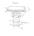
- FIG. 13 is an explanatory drawing that shows an arrangement in which spherical aberration is corrected by using a plurality of lenses placed between a light source and an objective lens, in the optical recording/reproducing apparatus of the present invention.
- FIG. 14 is an explanatory drawing that shows an operation for correcting spherical aberration in the optical recording/reproducing apparatus of the present invention.
- FIG. 15 is an explanatory drawing that shows another operation for correcting spherical aberration in the optical recording/reproducing apparatus of the present invention.
- FIG. 16 is an explanatory drawing that shows a state in which recording or reproducing is carried out on a recording medium having a recording layer of a single layer by using an optical recording/reproducing apparatus in accordance with the present invention.
- FIG. 17 is an explanatory drawing that shows one example of a combination lens in a conventional technique.
- FIG. 18 is an explanatory drawing that shows another example of a combination lens in a conventional technique.
- FIG. 1 shows an essential portion of an optical head in an optical recording/reproducing apparatus in accordance with the present invention.
- a first lens 2 may constitute a first group of lenses
- a second lens 3 may constitute a second group of lenses.
- each group of lenses only include one lens; however, this may include a plurality of lenses.
- FIG. 1 an explanation will be given of a combination lens and a spherical-aberration correcting mechanism formed by a voice coil motor.
- the combination lens 1 is constituted by two lenses, that is, the first lens 2 on the light source side and the second lens 3 on the side opposite to the light source with the second lens 2 located in between.
- the second lens 3 upon carrying out recording or reproducing on or from the recording medium 11 , the second lens 3 is located on the recording medium 11 side.
- the second lens 3 is secured to a magnet 4 , and the magnet 4 is supported by a plate spring 6 through a magnet support member 5 .
- a coil 7 is supported by a coil support member 8 .
- a voice coil motor 9 constituted by the magnet 4 , the magnet support member 5 , the plate spring 6 and the coil 7 , allows the second lens 3 to shift in the focusing direction (in a direction parallel to the normal to the recording medium 11 ) by applying a positive or negative current to the coil 7 . In other words, this makes it possible to change the gap between the first lens 2 and the second lens 3 .
- the combination lens 1 , the voice coil motor 9 and other supporting members, etc. are housed inside a lens barrel 10 of the combination lens.
- the combination lens barrel 10 is driven in focusing and radial directions of a recording medium 11 by an FR actuator (not shown).
- the combination lens 1 has a lens gap d 4 , and is designed so as to minimize the spherical aberration of a light spot formed by converging light transmitted through a light-transmitting body 12 having an optical thickness of t 4 .
- the light-transmitting body 12 is made of a transparent material that transmits light, and corresponds to a light-transmitting layer of a recording medium, on which assumption is made at the time of designing lenses.
- this light-transmitting body or light-transmitting layer is referred to as a cover glass layer or a protective layer, and made of various kinds of materials, such as polycarbonate (PC), glass or UV cure resins.
- the size of the spherical aberration of a light spot formed by converging light by the combination lens 1 changes depending on the thickness and refractive index of the light-transmitting body (or the light-transmitting layer), the refractive index, and the gap between lenses in the combination lens. Therefore, the gap of the lenses of the combination lens is fixed, and when the sizes of the spherical aberrations of light spots formed by converged light rays that have passed through different light-transmitting bodies are the same, it is assumed that the optical thicknesses of these light-transmitting bodies are the same.
- the present recording medium is provided with a light-transmitting layer, a recording layer and, if there are a plurality of recording layers, a light-transmitting layer between the recording layers; and in the following description, in some cases, the light-transmitting layer, the recording layer and the light-transmitting layer between the recording layers, which are located from the surface of the recording medium on the combination lens side up to the position in the recording medium on which light spot is formed may be referred to collectively as a light-transmitting layer.
- FIG. 3 shows a case in which, of the two recording layers, a converged light spot is formed on the first layer 13 closer to the combination lens 1 side of the recording medium 11 .
- the recording medium 11 has a laminated construction that is constituted by a light-transmitting layer 20 , a first recording layer 13 , a light-transmitting layer 21 placed between recording layers, a second recording layer 14 and a substrate layer 22 , which are formed in succession in this order from the combination lens side of the recording medium 11 .
- the lens gap of the combination lens 1 as explained in FIG. 2 is changed to d 1 (corresponding DIS( 1 ) in claims), with the result that light from a light-source, not shown, is allowed to pass through the optical thickness ti from the surface of the recording medium 11 on the combination lens side up to the first recording layer 13 to be converged so that the spherical aberration occurring on the converged light spot is corrected.
- the FR actuator carries out the positioning operation of the converged light spot onto the recording layer, and the spherical-aberration correcting mechanism carries out the correction of spherical aberration of the converged light spot.
- a current is applied to the voice coil motor 9 (see FIG. 1 ), and the applied current is represented by +i 1 (or ⁇ i 1 ).
- the applied current +i 1 or ⁇ i 1 corresponds to ec 1 in claims.
- FIG. 4 shows a case in which, of the two recording layers, a converged light spot is formed on the second recording layer 14 farther from the combination lens side of the recording medium 11 .
- the lens gap of the combination lens 1 as explained in FIG. 2 is changed to d 2 (corresponding to DIS(N) in claims), with the result that light is allowed to pass through the optical thickness t 2 from the surface of the recording medium 11 on the combination lens side up to the second recording layer 14 to be converged so that the spherical aberration occurring on the converged light spot is corrected.
- a current is applied to the voice coil motor 9 , and the applied current is represented by ⁇ i 2 (or +i 2 ).
- the applied current +i 2 or ⁇ i 2 corresponds to ecN in claims.
- FIG. 5 shows a case in which the lens gap of the combination lens 1 as explained in FIG. 2 is set to d 3 (corresponding to dst( 3 ) in claims).
- the spherical-aberration correcting mechanism is arranged so that, at this time, the current to be applied to the voice coil motor 9 becomes virtually zero.
- FIG. 5 shows a state in which a converged light spot is formed at a position which allows the optical thickness from the surface of the recording medium 11 on the combination lens side to be set at t 3 .
- the voice coil motor 9 it is possible to provide a virtually linear relationship with respect to the relationship between the applied current and the amount of shift of the body to be driven (in this case, the second lens 3 ), and in this case also, the voice coil motor 9 is designed in such a manner.
- the relationship between the optical thickness of the light-transmitting layer in this case, the optical thickness from the surface of the recording medium on the combination lens side up to the position at which a converged light spot is formed
- the spherical-aberration correcting mechanism is designed so that the applied current becomes zero at a neutral point (where the lens gap is d 3 ) of the spherical-aberration correcting mechanism.
- the relationship between applied currents to the voice coil motor 9 in the states as shown in FIGS. 3 and 4 is represented as follows:
- the applied current is set to negative or positive.
- the applied current i in the state of FIG. 4 is represented as follows:
- 2 ⁇
- 2 ⁇
- the spherical-aberration correcting mechanism is arranged so that the applied current becomes virtually zero in the state of FIG. 5 ; thus, the power consumption is reduced to 1 ⁇ 2, thereby making it possible to cut the power consumption.
- the voice coil motor 9 since the voice coil motor 9 is housed inside the combination lens barrel 10 , the coil 7 tends to be heated (or generated heat resides without being released) upon application of a current to the coil 7 . Therefore, it is more preferable to achieve low power consumption and minimized maximum applied current, and these effects can be obtained by arranging the spherical-aberration correcting mechanism so that the applied current becomes virtually zero in the state of FIG. 5 . The reason for this is explained as follows:
- the coil support member 8 and other parts are subjected to thermal expansion, with the result that the lens gap is altered.
- the applied current having a predetermined size is applied to the voice coil motor 7 so as to correct the spherical aberration of the light spot converged on each of the recording layers of the recording medium 11 .
- the spherical aberration of the converged light spot becomes greater, giving adverse effects on information recording and reproducing processes.
- the adverse effects become greater.
- the optical thickness t 3 of FIG. 5 and the optical thickness t 4 of the light-transmitting body of FIG. 2 are made virtually coincident with each other.
- the lens gap d 3 and the lens gap d 4 are also made virtually coincident with each other, and the recording densities of the recording layer at two positions of the optical thicknesses of t 3 + ⁇ t and t 3 ⁇ t (that is, a position at which the optical thicknesses are the same with t 3 located in between) are made equal to each other.
- ⁇ t is not equal to zero.
- FIGS. 6 ( a ), 6 ( b ) and 6 ( c ) as well as FIGS. 7 ( a ), 7 ( b ) and 7 ( c ), an explanation will be given of the effects of this arrangement.
- FIG. 6 ( a ) and FIG. 7 ( a ) show the relationship (before the spherical aberration correction and after the correction) between the optical thickness (corresponding to the optical thickness from the surface of the recording medium on the combination lens side) and the spherical aberration.
- FIG. 6 ( b ) and FIG. 7 ( b ) show the relationship between the optical thickness (corresponding to the optical thickness from the surface of the recording medium on the combination lens side) and the gap between the first lens and the second lens at the time of correcting the spherical aberration.
- FIG. 6 ( c ) and FIG. 7 ( c ) show the relationship between the optical thickness (corresponding to the optical thickness from the surface of the recording medium on the combination lens side) and the applied current that is supplied to the voice coil motor at the time of correcting the spherical aberration.
- FIGS. 6 ( a ) through 6 ( c ) show characteristics of a combination lens and explains the case in which, with respect to light rays that have passed through a light-transmitting body having an optical thickness of 80 ⁇ m and a refractive index of 1.53, and have been converged, the combination lens is designed so as to minimize the spherical aberration of the converged light spot; and in this case, the lens gap is set to 1.572 mm and the numerical aperture is set to 0.85.
- FIGS. 6 ( a ) through 6 ( c ) show the case in which the first layer is located at a position 80 ⁇ m apart from the surface of the recording medium on the combination lens side and the second layer is located at a position 120 ⁇ m apart therefrom; and the refractive index between them is set to a constant value of 1.53.
- the spherical aberration remaining after the spherical aberration correction is a minimum at the position of 80 ⁇ m, and becomes a maximum at the position of 120 ⁇ m.
- the lens gap is 1.477 mm when an attempt is made to correct the spherical aberration in the case of the thickness of the recording medium of 120 ⁇ m.
- the values of applied currents to the voice coil motor, used for respectively correcting the spherical aberrations of light spots converged on the first recording layer and the second recording layer, are made virtually coincident with each other.
- FIGS. 7 ( a ) through 7 ( c ) show characteristics of a combination lens and explains the case in which, with respect to light rays that have passed through a light-transmitting body having an optical thickness of 100 ⁇ m and a refractive index of 1.53, and have been converged, the combination lens is designed so as to minimize the spherical aberration of the converged light spot; and in this case, the lens gap is set to 1.512 mm and the numerical aperture is set to 0.85.
- FIGS. 7 ( a ) through 7 ( c ) show the case in which the first recording layer is located at a position 80 ⁇ m apart from the surface of the recording medium on the combination lens side and the second recording layer is located at a position 120 ⁇ m apart therefrom; and the refractive index between them is set to a constant value of 1.53.
- the recording medium thickness t 3 which can be corrected by using the lens gap d 3 in FIG. 5 , and the optical thickness t 4 (100 ⁇ m in this case) of the light-transmitting body determined at the time of lens designing shown in FIG. 2 are allowed to virtually coincide with each other (that is, d 3 and d 4 are also made virtually coincident with each other). Therefore, the value of the spherical aberration remaining after the spherical aberration correction is a minimum at the position of 100 ⁇ m, and the sizes of the spherical aberrations exerted at the positions of 80 ⁇ m and 120 ⁇ m are also made virtually coincident with each other.
- the above-mentioned arrangement is characterized in that: the optical thickness t 3 of FIG. 5 and the optical thickness t 4 of the light-transmitting body of FIG.
- the recording layers are located at positions of the optical thicknesses of t 3 + ⁇ t and t 3 ⁇ t (in this case, ⁇ t is 20 ⁇ m); and the relationship between the optical thickness of the light-transmitting layer (in this case, the optical thickness from the surface of the recording medium on the combination lens side to the position at which a converged light spot is formed) and the spherical aberration has a linear relationship; therefore, the spherical aberrations (after correction) exerted on light spots converged on the respective recording layers are allowed to have smaller maximum values, and also made virtually equal to each other.
- the sizes of the converged light spots on the two recording layers can also be made virtually coincident with each other. Consequently, it becomes possible to make the recording densities of the respective recording layers coincident with each other; thus, upon carrying out information recording or reproducing on or from the two recording layers, even when switching is made between the recording layers to be reproduced or recorded, it is not necessary to change the number of rotations at which the recording medium is rotated. In other words, it is not necessary to provide dead time for waiting for the spindle servo to stand still. In other words, it is possible to reduce power consumption at the time of correcting spherical aberration, and consequently to reduce loads imposed on systems such as a rotation controlling system for the recording medium.
- a recording medium 16 has a single recording layer 15 , and its optical thickness from the surface of the recording medium 16 on the combination lens side to the recording layer 15 is set to t 5 .
- this is designed to be virtually coincident with the optical thickness t 3 shown in FIG. 5 .
- the lens gap d 5 set so as to correct the spherical aberration of a light spot converged on the recording layer 15 , is also allowed to virtually coincide with the lens gap d 3 shown in FIG. 5 .
- the applied current to be supplied to the spherical-aberration correcting mechanism that is, a voice coil motor 9 (see FIG. 1 )
- the spherical-aberration correcting mechanism that is, a voice coil motor 9 (see FIG. 1 )
- an arrangement is made so that the optical thickness t 4 of the light-transmitting body shown in FIG. 2 and the optical thickness t 5 shown in FIG. 8 (the optical thickness from the surface of the recording medium 16 on the combination lens side to the recording layer 15 ) are made virtually coincident with each other.
- the recording medium 16 having a single recording layer shown in FIG. 8
- an optical recording/reproducing apparatus for recording/reproducing information on/from the recording medium 11 having two recording layers shown in FIG.
- this arrangement makes it possible to minimize the spherical aberration of the light spot converged on the recording layer 15 of the recording medium 16 having a single recording layer, and also to make the size of the converged light spot smaller. Therefore, it is possible to increase the recording density of the recording medium 16 having a single recording layer 15 , and the recording medium having such as arrangement provides a recording medium suitable for the optical recording/reproducing apparatus of the present invention.
- the spherical-aberration correcting mechanism consisting of two lens groups, each constituted by at least one lens, a combination lens for converging light rays from the light source on the optical recording medium is used; however, the spherical-aberration correcting mechanism may be installed in a separated manner from the combination lens (objective lens) for converging light rays from the light source onto the recording medium.
- the spherical-aberration may be corrected by a plurality of lenses placed between the light source and the objective lens.
- FIGS. 9 through 16 an explanation will be given of an example in which spherical-aberration is corrected by a plurality of lenses placed between the light source and the objective lens.
- various types of objective lens may be used, and in FIGS.
- an objective lens 27 which is designed so that, when light rays having no spherical aberration are made incident thereon, the spherical aberration of a light spot which is formed by the light rays transmitted through a light-transmitting body having an optical thickness that is optically equivalent to an optical thickness P 3 ⁇ P ( ⁇ P ⁇ 0), that is, the spherical aberration of the converged light spot on the first recording layer 13 is minimized.
- the optical thickness at the mid-point between the first recording layer 13 and the second recording layer 14 is defined as p 3
- the optical thickness of the second recording layer 14 is defined as p 3 + ⁇ p.
- two lens-group components in which the lens group gap is adjusted are related not to the objective lens 27 , but to a lens-group component 28 constituted by a first lens (lens group) 25 and a second lens (lens group) 26 , as described below.
- the first lens 25 and the second lens 26 are placed with their respective centers being coincident on the light axis of the light source, and the first lens 25 is placed closer to the light source.
- the first lens 25 which is a plano-concave lens, is placed with its flat face facing the light source side (that is, with its concave face facing the second lens 26 side).
- the second lens 26 which is a plane-convex lens, is placed with its convex face facing the concave face of the first lens 25 .
- divergent light rays released from a light source 23 , are formed into parallel light rays by a collimator lens 24 , and made incident on the first lens 25 .
- the resulting divergent light rays through the first lens 25 are made incident on the second lens 26 .
- the light rays released from the second lens 26 are converged on the first recording layer 13 or the second recording layer 14 of the recording medium 11 by the objective lens 27 .
- the objective lens is driven by an FR actuator, no shown.
- the first recording layer 13 and the second recording layer 14 are located at positions respectively having optical thicknesses P 3 ⁇ P and P 3 + ⁇ P from the surface of the recording medium 11 on the objective lens side.
- the first lens 25 and the second lens 26 are driven by a voice coil motor 9 , and when information is recorded/reproduced on/from the first recording layer 13 , an applied current +r 1 (or ⁇ r 1 ) is inputted thereto so as to set the lens gap-to h 1 (see FIG. 10 ), and when information is recorded/reproduced on/from the second recording layer 14 , an applied current ⁇ r 2 (or +r 2 ) is inputted thereto so as to set the lens gap to h 2 (see FIG. 11 ).
- the voice coil motor 9 has basically the same construction as that shown in FIG. 1 ; therefore, a detailed description thereof is omitted. Additionally, the applied current +r 1 or ⁇ r 1 corresponds to ec 1 and the applied current ⁇ r 2 or +r 2 corresponds to ecN respectively in the claims.
- h 3 ( h 1 + h 2 )/2.
- lens group gap h 3 corresponds to dst ( 3 ) in the claims.
- the objective lens 27 is designed so that, when light rays having no spherical aberration are made incident thereon, the spherical aberration of a light spot which is formed by the light rays transmitted through the light-transmitting layer having an optical thickness of p 3 ⁇ p is made smallest; therefore, the first lens 25 and the second lens 26 , which are subjected to a correction in the spherical aberration, are preferably designed so that, when the lens group gap is set to h 1 (corresponding to DIS( 1 ) disclosed in claims), the spherical aberration of the light rays transmitted through the two lenses is minimized, and when the lens group gap is set to h 2 (corresponding to DIS(N) disclosed in claims), the spherical aberration of a light spot that is formed by converging by using the objective lens 27 the light rays released from the second lens 26 and transmitted through a light-transmitting layer having an optical thickness of p 3 + ⁇ p, that is, the spher
- the first lens, the second lens and the objective lens may be designed so that, in response to a change in the gap between the first lens and the second lens, the amount of spherical aberration of the light spot derived from light that has released through the second lens and converged by the objective lens is made to change in a linear fashion, and so that the relationship between the error in the optical thickness of the light-transmitting layer and the spherical aberration is also made to change in a linear fashion.
- the lens group gap is h 3
- the spherical aberration of the light spot converged at the position having an optical thickness of virtually p 3 is minimized by the objective lens 27 .
- the above-mentioned arrangement makes it possible to reduce the maximum applied current and the power consumption in the spherical-aberration correcting mechanism in the same manner as the combination lens (objective lens) consisting of a plurality of lenses, and also to prevent the operation of the spherical-aberration correcting mechanism from being unstable due to heat generated by the coil, etc. Moreover, since the spherical-aberration correcting mechanism is installed in a manner separated from the objective lens, it is possible to drive the objective lens at higher speeds by the FR actuator.
- the objective lens is designed so that, in the case when light rays having virtually no spherical aberration are made incident thereon, the light spot derived from the light rays transmitted through the light-transmitting body 12 a having an optical thickness of p 4 (see FIG. 12 ) optically equivalent to the optical thickness p 3 , that is, the converged light spot at the mid-position between the first recording layer 13 and the second recording layer 14 in the optical recording medium, is allowed to have a minimum spherical aberration.
- the two lens group components the gap of which is adjusted are not the objective lens 37 , but lens group components 38 consisting of the first lens (lens group) 35 and the second lens (lens group) 36 , which will be described below.
- the first lens and the second lens are designed in the following manner: When the lens group gap between the first lens 35 and the second lens 36 is set to k 3 (dst ( 3 )), the spherical aberration of light rays transmitted through these two lenses is minimized (FIG.
- the lens arrangement that satisfies the above-mentioned conditions can be obtained by a general designing practice.
- the sizes of the converged light spots can also be made virtually the same with each other. Consequently, upon carrying out information recording or reproducing on or from the two recording layers, even when switching is made between the recording layers to be reproduced or recorded, it is not necessary to change the number of rotations at which the recording medium is rotated. In other words, it is not necessary to provide dead time for waiting for spindle servo to stand still.
- FIG. 16 shows a recording medium 16 having a single recording layer 15 , and the optical thickness from the surface of the recording medium 16 on the objective lens side to the recording layer 15 is set to p 5 .
- the optical thickness p 3 and the optical thickness p 5 shown in FIG. 9 , are designed to be virtually coincident with each other.
- the lens group gap h 5 for correcting the spherical aberration of a light spot converged on the recording layer 15 is virtually coincident with the lens group gap h 3 shown in FIG. 9 . That is, in the arrangement of FIG.
- the optical thickness p 3 and the optical thickness p 5 may be arranged so as to be virtually coincident with each other.
- the lens group gap h 6 for correcting the spherical aberration of a light spot converged on the recording layer 15 is virtually coincident with the lens group gap k 3 shown in FIG. 13 . That is, in the arrangement of FIG.
- the applied current to be supplied to the spherical-aberration correcting mechanism that is, a voice coil motor
- the applied current to be supplied to the spherical-aberration correcting mechanism can be made virtually zero, thereby making it possible to reduce the power consumption.
- an arrangement shown in FIG. 13 , may be used to record/reproduce information on/from the recording medium having a single recording layer.
- the objective lens shown in FIG. 13 , is designed so that, when light rays having virtually no spherical aberration are made incident thereon, the spherical aberration of the light spot converged on a position having an optical thickness of p 3 is made the smallest.
- the first lens 35 and the second lens 36 are designed so that, when the lens group gap is k 3 , the spherical aberration of light rays released from the second lens 36 is made smallest.
- the optical thickness p 5 (see FIG. 16 ) and the optical thickness p 3 (see FIG. 13 ) virtually coincident with each other, even in the case when information is recorded or reproduced on or from a recording medium having only a single recording layer by using an optical recording/reproducing apparatus for recording/reproducing information on/from a recording medium having two recording layers, it is possible to minimize the spherical aberration of the light spot converged on the recording layer of the recording medium having only a single recording layer. In other words, since the size of the converged light spot is reduced, it is possible to improve the recording density of a recording medium having a single recording layer, and also to reduce the power consumption at the time of recording or reproducing information.
- the above-mentioned description has exemplified a case in which a plano-concave lens is used as the first lens and a plane-convex lens is used as the second lens; however, the arrangement of the lens is not particularly limited, and a plane-convex lens may be used as the first lens and a plano-concave lens may be used as the second lens. Moreover, two plane-convex lenses may be combined.
- the above-mentioned spherical-aberration correcting mechanism may be applied to arrangements generally referred to as beam expander and relay lens. That is, the present invention is applicable to any arrangement as long as it allows the amount of spherical aberration to change by changing the lens group gap.
- the above-mentioned embodiment has exemplified a case in which the voice coil motor is used as the spherical-aberration correcting mechanism; however, another mechanism for changing the lens gap by using an electric driving device such as a piezoelectric element may be used with the same effects.
- the gap between a collimator lens and a light source is changed by the spherical-aberration correcting mechanism; and in this case, the neutral point of the spherical-aberration correcting mechanism is set at a point which allows the focal distance of the collimator lens and the gap between the collimator lens and the light source to coincide with each other.
- the present embodiment has exemplified a recording medium having two recording layers; however, the same effects are obtained even in the case of a recording medium having more recording layers (not less than three).
- the above-mentioned description has exemplified a case in which a light-transmitting layer, a plurality of recording layers, a light-transmitting layer interpolated between the recording layers and a substrate layer are stacked in succession from the combined lens side; however, a so-called joined disk having two of such recording media joined to each other may be used with the same effects. In this case, however, recording and reproducing processes have to be carried out from both of the sides of the recording medium. Moreover, with respect to a recording medium having a single recording layer, a joined disk of such recording media may be used.
- the optical thickness from the surface of the recording medium on the lens side to the recording layer it is possible to define it by using values of the refractive index and the thickness of the surface of the recording medium on the lens side to the recording layer (for example, a thickness measured by focusing the objective lens to each layer), and upon designing the recording medium, these values are also set within predetermined ranges.
- the refractive index and the thickness of the surface of the recording medium on the lens side to the recording layer are set in predetermined ranges. That is, it can be said that the optical thickness is maintained within a predetermined range.
- the optical thickness of a recording medium having a plurality of recording layers is defined as follows:
- a refractive index n 1 and a thickness s 1 which are a predetermined refractive index and a thickness located within the thickness from the surface of the recording medium on the lens side to the recording layer, are the refractive index and the thickness of the first recording layer, while assuming that a lens gap is d 1 (h 1 ), the lens gap being obtained at the time of forming a converged light spot by a combination lens (or an objective lens and two lens groups) on the first recording layer having the refractive index n 1 and the thickness s 1 , and when it is also assumed that a refractive index n 2 and a thickness s 2 , which are a predetermined refractive index and a thickness located within the thickness from the surface of the recording medium on the lens side to the recording layer, are the refractive index and the thickness of
- a light-transmitting layer is located between a recording layer and another recording layer in the proximity of said recording layer, and the optical thickness from the surface of the recording medium on the lens side to the first recording layer and the optical thickness (refractive index and thickness) of the light-transmitting layer between these recording layers is sometimes different; however, in such a case, the optical thickness from the surface of the recording medium on the lens side to the first recording layer and the optical thickness of the light-transmitting layer between the recording layers may be combined, and based upon the above-mentioned idea, the lens group gap may be determined.
- the optical recording/reproducing apparatus of the present invention which records/reproduces information on/from a recording medium having recording layers the number of which is represented by N (N ⁇ 2) by converging light rays from a light source thereon, is provided with: two lens groups, each including at least one lens, placed in a light path from the light source to the recording medium; and a spherical-aberration correcting mechanism which changes a lens group gap between the two groups by means of electrical driving so as to correct spherical aberration of a converged light spot formed on each of the recording layers, wherein, supposing that the recording layers having N number of layers are a first recording layer, . . .
- an N-th recording layer the lens group gap is represented by DIS( 1 ) at the time of correcting the spherical aberration of the converged light spot formed on the first recording layer, and the intensity of an applied current to the spherical-aberration correcting mechanism is ecN, said spherical-aberration correcting mechanism is operated so as to satisfy a relationship:
- the size of the applied current to the spherical-aberration correcting mechanism is set to zero.
- the two groups of lenses constitute an objective lens for converging light rays from the light source onto the recording medium
- the two groups of lenses forming the objective lens are set in such a manner that, when the lens group gap is d 4 , a light spot derived from light rays transmitted through a light-transmitting body having an optical thickness is t 4 has a minimum spherical aberration, and the lens group gap d 4 and the dst( 3 ) are set so as to be virtually the same.
Abstract
Description
|ec1|=|ecN|
and when the applied current to the spherical-aberration correcting mechanism is zero, a lens group gap dst(3) satisfies the following relationship:
dst(3)=[DIS(1)+DIS(N)]/2.
|ec1|=|ecN|,
and when the applied current to the spherical-aberration correcting mechanism is zero, a lens group gap dst(3) satisfies the following relationship:
dst(3)=[DIS(1)+DIS(N)]/2,
|i1|=|i2| (2)
|i|=2×|i 1|=2×|i 2| (3)
Therefore, in the manner as described in the present invention, when the spherical-aberration correcting mechanism is designed so that the applied current becomes virtually zero in the state of
1.523 mm=(1.572 mm+1.477 mm)/2.
|r1|=|r2|.
Claims (3)
dst(3)=(DIS(1)+DIS(N))/2.
Priority Applications (2)
| Application Number | Priority Date | Filing Date | Title |
|---|---|---|---|
| US10/676,973 US6914730B2 (en) | 1999-05-10 | 2003-09-30 | Optical recording/reproducing apparatus |
| US11/107,243 US7898748B2 (en) | 1999-05-10 | 2005-04-14 | Optical recording/reproducing apparatus |
Applications Claiming Priority (4)
| Application Number | Priority Date | Filing Date | Title |
|---|---|---|---|
| JP12809199 | 1999-05-10 | ||
| JP11-128091 | 1999-05-10 | ||
| US09/566,615 US6728179B1 (en) | 1999-05-10 | 2000-05-09 | Apparatus and method for optical recording/reproducing information including electrical spherical-aberration correction mechanism having low power consumption |
| US10/676,973 US6914730B2 (en) | 1999-05-10 | 2003-09-30 | Optical recording/reproducing apparatus |
Related Parent Applications (1)
| Application Number | Title | Priority Date | Filing Date |
|---|---|---|---|
| US09/566,615 Division US6728179B1 (en) | 1999-05-10 | 2000-05-09 | Apparatus and method for optical recording/reproducing information including electrical spherical-aberration correction mechanism having low power consumption |
Related Child Applications (1)
| Application Number | Title | Priority Date | Filing Date |
|---|---|---|---|
| US11/107,243 Division US7898748B2 (en) | 1999-05-10 | 2005-04-14 | Optical recording/reproducing apparatus |
Publications (2)
| Publication Number | Publication Date |
|---|---|
| US20040061951A1 US20040061951A1 (en) | 2004-04-01 |
| US6914730B2 true US6914730B2 (en) | 2005-07-05 |
Family
ID=14976188
Family Applications (3)
| Application Number | Title | Priority Date | Filing Date |
|---|---|---|---|
| US09/566,615 Expired - Lifetime US6728179B1 (en) | 1999-05-10 | 2000-05-09 | Apparatus and method for optical recording/reproducing information including electrical spherical-aberration correction mechanism having low power consumption |
| US10/676,973 Expired - Fee Related US6914730B2 (en) | 1999-05-10 | 2003-09-30 | Optical recording/reproducing apparatus |
| US11/107,243 Expired - Fee Related US7898748B2 (en) | 1999-05-10 | 2005-04-14 | Optical recording/reproducing apparatus |
Family Applications Before (1)
| Application Number | Title | Priority Date | Filing Date |
|---|---|---|---|
| US09/566,615 Expired - Lifetime US6728179B1 (en) | 1999-05-10 | 2000-05-09 | Apparatus and method for optical recording/reproducing information including electrical spherical-aberration correction mechanism having low power consumption |
Family Applications After (1)
| Application Number | Title | Priority Date | Filing Date |
|---|---|---|---|
| US11/107,243 Expired - Fee Related US7898748B2 (en) | 1999-05-10 | 2005-04-14 | Optical recording/reproducing apparatus |
Country Status (3)
| Country | Link |
|---|---|
| US (3) | US6728179B1 (en) |
| KR (1) | KR100334920B1 (en) |
| NL (1) | NL1015136C2 (en) |
Cited By (2)
| Publication number | Priority date | Publication date | Assignee | Title |
|---|---|---|---|---|
| US20050105407A1 (en) * | 2003-09-29 | 2005-05-19 | Funai Electric Co., Ltd. | Optical pickup apparatus |
| US20100002313A1 (en) * | 2008-07-02 | 2010-01-07 | Jacques Duparre | Method and apparatus providing singlet wafer lens system with field flattener |
Families Citing this family (18)
| Publication number | Priority date | Publication date | Assignee | Title |
|---|---|---|---|---|
| JP4085812B2 (en) * | 2000-09-06 | 2008-05-14 | 株式会社日立製作所 | Optical head and optical disk apparatus |
| WO2002065461A2 (en) * | 2001-01-08 | 2002-08-22 | Zen Research (Ireland), Ltd. | Method and apparatus for writing multiple tracks of an optical disk |
| US6934226B2 (en) * | 2001-04-12 | 2005-08-23 | Matsushita Electric Industrial Co., Ltd. | Optical disk apparatus |
| US6968563B2 (en) * | 2001-07-27 | 2005-11-22 | Kabushiki Kaisha Toshiba | Optical head |
| JP4373036B2 (en) * | 2001-08-31 | 2009-11-25 | パイオニア株式会社 | Optical pickup |
| KR100618484B1 (en) * | 2002-01-22 | 2006-08-31 | 후지쯔 가부시끼가이샤 | Floating slider, and magneto-optical storage device comprising it |
| JP4093233B2 (en) * | 2002-12-10 | 2008-06-04 | 日本ビクター株式会社 | Optical disc apparatus and aberration correction method used therefor |
| JP2005108321A (en) * | 2003-09-30 | 2005-04-21 | Konica Minolta Opto Inc | Optical pickup device and optical information recording and reproducing device |
| US7738340B2 (en) * | 2003-11-27 | 2010-06-15 | Ricoh Company, Ltd. | Optical disk apparatus with aberration correcting part, and optical disk |
| WO2005078712A1 (en) * | 2004-01-19 | 2005-08-25 | Koninklijke Philips Electronics N.V. | Objective lens |
| JP2006018948A (en) * | 2004-07-02 | 2006-01-19 | Ricoh Co Ltd | Device for correcting spherical aberration, and optical pickup device |
| JP3992072B2 (en) * | 2004-07-13 | 2007-10-17 | コニカミノルタオプト株式会社 | Optical pickup device |
| KR100656640B1 (en) * | 2004-12-21 | 2006-12-11 | 엘지전자 주식회사 | Optical writing and reading apparatus and its method |
| KR100675863B1 (en) * | 2005-01-24 | 2007-02-02 | 삼성전자주식회사 | Optical pick-up device |
| JP2007018620A (en) * | 2005-07-08 | 2007-01-25 | Canon Inc | Information recording and reproducing device |
| WO2007117082A2 (en) * | 2006-04-11 | 2007-10-18 | Lg Electronics Inc. | Recording and reproducing apparatus, recording and reproducing method, and method of determining type of recording medium |
| JP2007328875A (en) * | 2006-06-08 | 2007-12-20 | Sharp Corp | Optical pickup apparatus |
| CN102105829B (en) * | 2008-07-25 | 2013-11-13 | 日立麦克赛尔株式会社 | Drive device, image acquisition device, and electronic equipment |
Citations (7)
| Publication number | Priority date | Publication date | Assignee | Title |
|---|---|---|---|---|
| US5157555A (en) * | 1991-12-04 | 1992-10-20 | General Electric Company | Apparatus for adjustable correction of spherical aberration |
| JPH10188301A (en) | 1996-12-20 | 1998-07-21 | Sony Corp | Optical disk recording and reproducing device and its method |
| JPH10255290A (en) | 1997-03-12 | 1998-09-25 | Sony Corp | Objective lens for optical pickup |
| US6091549A (en) * | 1998-04-14 | 2000-07-18 | Siros Technologies, Inc. | Method and apparatus for adjustable spherical aberration correction and focusing |
| US6108139A (en) * | 1996-10-28 | 2000-08-22 | Nec Corporation | Optical head device and method of information reproduction using the same |
| US6418108B1 (en) * | 1998-01-09 | 2002-07-09 | Sony Corporation | Optical head, recording and/or reproducing method and apparatus and method for detecting thickness |
| US6567365B1 (en) * | 1999-09-30 | 2003-05-20 | Koninklijke Philips Electronics N.V. | Optical scanning device |
Family Cites Families (13)
| Publication number | Priority date | Publication date | Assignee | Title |
|---|---|---|---|---|
| NL8800133A (en) * | 1988-01-21 | 1989-08-16 | Philips Nv | DEVICE FOR SCANNING AN INFORMATION SHEET WITH OPTICAL RADIATION. |
| JP3413427B2 (en) * | 1993-12-09 | 2003-06-03 | キヤノン株式会社 | Optical recording / reproducing device |
| US5625609A (en) * | 1995-03-13 | 1997-04-29 | International Business Machines Corporation | Multiple data layer optical disk drive system with fixed aberration correction and optimum interlayer spacing |
| US5838653A (en) * | 1995-10-04 | 1998-11-17 | Reveo, Inc. | Multiple layer optical recording media and method and system for recording and reproducing information using the same |
| JP3510947B2 (en) * | 1995-12-01 | 2004-03-29 | パイオニア株式会社 | Optical pickup device |
| KR100189899B1 (en) * | 1996-02-14 | 1999-06-01 | 윤종용 | Optical disc perception method having different thickness and optical apparatus using it |
| JPH09251645A (en) * | 1996-03-15 | 1997-09-22 | Sony Corp | Recording medium recording and reproducing device and method therefor |
| JPH11110768A (en) * | 1997-09-30 | 1999-04-23 | Sony Corp | Optical pickup device |
| JPH11110794A (en) * | 1997-09-30 | 1999-04-23 | Sony Corp | Lens driving device and optical head |
| EP0984440A3 (en) * | 1998-09-04 | 2000-05-24 | Matsushita Electric Industrial Co., Ltd. | Aberration detection device and optical information recording and reproducing apparatus |
| EP1055230B1 (en) * | 1998-12-10 | 2007-09-12 | Koninklijke Philips Electronics N.V. | Device for optically scanning a record carrier |
| JP3836995B2 (en) * | 1999-05-06 | 2006-10-25 | シャープ株式会社 | Optical recording medium and optical recording / reproducing apparatus |
| JP2004039068A (en) * | 2002-07-02 | 2004-02-05 | Matsushita Electric Ind Co Ltd | Optical head |
-
2000
- 2000-05-09 KR KR1020000024583A patent/KR100334920B1/en not_active IP Right Cessation
- 2000-05-09 NL NL1015136A patent/NL1015136C2/en not_active IP Right Cessation
- 2000-05-09 US US09/566,615 patent/US6728179B1/en not_active Expired - Lifetime
-
2003
- 2003-09-30 US US10/676,973 patent/US6914730B2/en not_active Expired - Fee Related
-
2005
- 2005-04-14 US US11/107,243 patent/US7898748B2/en not_active Expired - Fee Related
Patent Citations (8)
| Publication number | Priority date | Publication date | Assignee | Title |
|---|---|---|---|---|
| US5157555A (en) * | 1991-12-04 | 1992-10-20 | General Electric Company | Apparatus for adjustable correction of spherical aberration |
| JPH05266511A (en) | 1991-12-04 | 1993-10-15 | General Electric Co <Ge> | Device for correcting spherical aberration |
| US6108139A (en) * | 1996-10-28 | 2000-08-22 | Nec Corporation | Optical head device and method of information reproduction using the same |
| JPH10188301A (en) | 1996-12-20 | 1998-07-21 | Sony Corp | Optical disk recording and reproducing device and its method |
| JPH10255290A (en) | 1997-03-12 | 1998-09-25 | Sony Corp | Objective lens for optical pickup |
| US6418108B1 (en) * | 1998-01-09 | 2002-07-09 | Sony Corporation | Optical head, recording and/or reproducing method and apparatus and method for detecting thickness |
| US6091549A (en) * | 1998-04-14 | 2000-07-18 | Siros Technologies, Inc. | Method and apparatus for adjustable spherical aberration correction and focusing |
| US6567365B1 (en) * | 1999-09-30 | 2003-05-20 | Koninklijke Philips Electronics N.V. | Optical scanning device |
Non-Patent Citations (1)
| Title |
|---|
| I. Ichimura, et al.; "O plue E"; Sharp; pp 175-181; vol. 22; No. 2; Feb. 2000 (with partial English translation). |
Cited By (4)
| Publication number | Priority date | Publication date | Assignee | Title |
|---|---|---|---|---|
| US20050105407A1 (en) * | 2003-09-29 | 2005-05-19 | Funai Electric Co., Ltd. | Optical pickup apparatus |
| US7315490B2 (en) * | 2003-09-29 | 2008-01-01 | Funai Electric Co., Ltd. | Optical pickup apparatus |
| US20100002313A1 (en) * | 2008-07-02 | 2010-01-07 | Jacques Duparre | Method and apparatus providing singlet wafer lens system with field flattener |
| US7920339B2 (en) * | 2008-07-02 | 2011-04-05 | Aptina Imaging Corporation | Method and apparatus providing singlet wafer lens system with field flattener |
Also Published As
| Publication number | Publication date |
|---|---|
| KR100334920B1 (en) | 2002-05-04 |
| US20050179804A1 (en) | 2005-08-18 |
| US7898748B2 (en) | 2011-03-01 |
| NL1015136C2 (en) | 2006-05-18 |
| US20040061951A1 (en) | 2004-04-01 |
| US6728179B1 (en) | 2004-04-27 |
| KR20000077192A (en) | 2000-12-26 |
| NL1015136A1 (en) | 2000-11-13 |
Similar Documents
| Publication | Publication Date | Title |
|---|---|---|
| US7898748B2 (en) | Optical recording/reproducing apparatus | |
| JP3435249B2 (en) | Optical head device and lens | |
| EP0762403B1 (en) | Optical disk apparatus and optical head thereof | |
| JP4502051B2 (en) | Optical recording medium | |
| EP1471514A2 (en) | Optical pickup device, optical information recording and reproducing apparatus, expander lens, coupling lens and chromatic aberration correcting optical element | |
| JP2000131603A (en) | Optical head and recording and reproducing device | |
| JP2001209966A (en) | Optical pickup | |
| JP3336829B2 (en) | Compound objective lens | |
| JP3527685B2 (en) | Optical recording / reproducing device | |
| JP2003115127A (en) | Optical pickup device | |
| JP2006147069A (en) | Optical pickup, aberration generating method for compensation, and optical information processor using the same | |
| US20060136951A1 (en) | Optical head capable of recording and reproducing information on any one of a plurality of kinds of optical information recording medium and optical information recording and reproducing apparatus using the same | |
| JP3368422B2 (en) | Lens device, optical head and optical disk device using the same | |
| EP0769777B1 (en) | An optical head unit for use in an information read/write apparatus | |
| JP3626035B2 (en) | Optical recording / reproducing device | |
| JP4076936B2 (en) | Optical recording / reproducing device | |
| JP4563444B2 (en) | Optical recording / reproducing device | |
| JP2000030299A (en) | Recording medium and optical head device applicable to device for recording and reproducing information suitable therefor | |
| US5640279A (en) | Beam splitter for optical reading and writing actuator | |
| JP2006252614A (en) | Optical pickup device and optical disk driving device using the same | |
| JPH09204688A (en) | Optical recording medium | |
| JPH1064115A (en) | Optical pickup device, and recording and/or reproducing device | |
| JP2004071081A (en) | Optical pickup and disk driving device | |
| WO2008114231A1 (en) | Optical apparatus | |
| JPH08286014A (en) | Objective lens of optical pickup |
Legal Events
| Date | Code | Title | Description |
|---|---|---|---|
| FEPP | Fee payment procedure |
Free format text: PAYOR NUMBER ASSIGNED (ORIGINAL EVENT CODE: ASPN); ENTITY STATUS OF PATENT OWNER: LARGE ENTITY |
|
| FPAY | Fee payment |
Year of fee payment: 4 |
|
| FPAY | Fee payment |
Year of fee payment: 8 |
|
| FEPP | Fee payment procedure |
Free format text: PAYER NUMBER DE-ASSIGNED (ORIGINAL EVENT CODE: RMPN); ENTITY STATUS OF PATENT OWNER: LARGE ENTITY Free format text: PAYOR NUMBER ASSIGNED (ORIGINAL EVENT CODE: ASPN); ENTITY STATUS OF PATENT OWNER: LARGE ENTITY |
|
| REMI | Maintenance fee reminder mailed | ||
| LAPS | Lapse for failure to pay maintenance fees | ||
| STCH | Information on status: patent discontinuation |
Free format text: PATENT EXPIRED DUE TO NONPAYMENT OF MAINTENANCE FEES UNDER 37 CFR 1.362 |
|
| FP | Lapsed due to failure to pay maintenance fee |
Effective date: 20170705 |