US6970362B1 - Electronic assemblies and systems comprising interposer with embedded capacitors - Google Patents
Electronic assemblies and systems comprising interposer with embedded capacitors Download PDFInfo
- Publication number
- US6970362B1 US6970362B1 US09/628,705 US62870500A US6970362B1 US 6970362 B1 US6970362 B1 US 6970362B1 US 62870500 A US62870500 A US 62870500A US 6970362 B1 US6970362 B1 US 6970362B1
- Authority
- US
- United States
- Prior art keywords
- interposer
- coupled
- power
- lands
- ground
- Prior art date
- Legal status (The legal status is an assumption and is not a legal conclusion. Google has not performed a legal analysis and makes no representation as to the accuracy of the status listed.)
- Expired - Lifetime, expires
Links
Images


Classifications
-
- H—ELECTRICITY
- H01—ELECTRIC ELEMENTS
- H01L—SEMICONDUCTOR DEVICES NOT COVERED BY CLASS H10
- H01L23/00—Details of semiconductor or other solid state devices
- H01L23/48—Arrangements for conducting electric current to or from the solid state body in operation, e.g. leads, terminal arrangements ; Selection of materials therefor
- H01L23/50—Arrangements for conducting electric current to or from the solid state body in operation, e.g. leads, terminal arrangements ; Selection of materials therefor for integrated circuit devices, e.g. power bus, number of leads
-
- H—ELECTRICITY
- H01—ELECTRIC ELEMENTS
- H01L—SEMICONDUCTOR DEVICES NOT COVERED BY CLASS H10
- H01L23/00—Details of semiconductor or other solid state devices
- H01L23/58—Structural electrical arrangements for semiconductor devices not otherwise provided for, e.g. in combination with batteries
- H01L23/64—Impedance arrangements
- H01L23/642—Capacitive arrangements
-
- H—ELECTRICITY
- H01—ELECTRIC ELEMENTS
- H01L—SEMICONDUCTOR DEVICES NOT COVERED BY CLASS H10
- H01L2224/00—Indexing scheme for arrangements for connecting or disconnecting semiconductor or solid-state bodies and methods related thereto as covered by H01L24/00
- H01L2224/01—Means for bonding being attached to, or being formed on, the surface to be connected, e.g. chip-to-package, die-attach, "first-level" interconnects; Manufacturing methods related thereto
- H01L2224/02—Bonding areas; Manufacturing methods related thereto
- H01L2224/04—Structure, shape, material or disposition of the bonding areas prior to the connecting process
- H01L2224/05—Structure, shape, material or disposition of the bonding areas prior to the connecting process of an individual bonding area
- H01L2224/0554—External layer
- H01L2224/0556—Disposition
- H01L2224/05571—Disposition the external layer being disposed in a recess of the surface
-
- H—ELECTRICITY
- H01—ELECTRIC ELEMENTS
- H01L—SEMICONDUCTOR DEVICES NOT COVERED BY CLASS H10
- H01L2224/00—Indexing scheme for arrangements for connecting or disconnecting semiconductor or solid-state bodies and methods related thereto as covered by H01L24/00
- H01L2224/01—Means for bonding being attached to, or being formed on, the surface to be connected, e.g. chip-to-package, die-attach, "first-level" interconnects; Manufacturing methods related thereto
- H01L2224/02—Bonding areas; Manufacturing methods related thereto
- H01L2224/04—Structure, shape, material or disposition of the bonding areas prior to the connecting process
- H01L2224/05—Structure, shape, material or disposition of the bonding areas prior to the connecting process of an individual bonding area
- H01L2224/0554—External layer
- H01L2224/05573—Single external layer
-
- H—ELECTRICITY
- H01—ELECTRIC ELEMENTS
- H01L—SEMICONDUCTOR DEVICES NOT COVERED BY CLASS H10
- H01L2224/00—Indexing scheme for arrangements for connecting or disconnecting semiconductor or solid-state bodies and methods related thereto as covered by H01L24/00
- H01L2224/01—Means for bonding being attached to, or being formed on, the surface to be connected, e.g. chip-to-package, die-attach, "first-level" interconnects; Manufacturing methods related thereto
- H01L2224/10—Bump connectors; Manufacturing methods related thereto
- H01L2224/15—Structure, shape, material or disposition of the bump connectors after the connecting process
- H01L2224/16—Structure, shape, material or disposition of the bump connectors after the connecting process of an individual bump connector
- H01L2224/161—Disposition
- H01L2224/16151—Disposition the bump connector connecting between a semiconductor or solid-state body and an item not being a semiconductor or solid-state body, e.g. chip-to-substrate, chip-to-passive
- H01L2224/16221—Disposition the bump connector connecting between a semiconductor or solid-state body and an item not being a semiconductor or solid-state body, e.g. chip-to-substrate, chip-to-passive the body and the item being stacked
- H01L2224/16225—Disposition the bump connector connecting between a semiconductor or solid-state body and an item not being a semiconductor or solid-state body, e.g. chip-to-substrate, chip-to-passive the body and the item being stacked the item being non-metallic, e.g. insulating substrate with or without metallisation
-
- H—ELECTRICITY
- H01—ELECTRIC ELEMENTS
- H01L—SEMICONDUCTOR DEVICES NOT COVERED BY CLASS H10
- H01L2924/00—Indexing scheme for arrangements or methods for connecting or disconnecting semiconductor or solid-state bodies as covered by H01L24/00
- H01L2924/0001—Technical content checked by a classifier
- H01L2924/00014—Technical content checked by a classifier the subject-matter covered by the group, the symbol of which is combined with the symbol of this group, being disclosed without further technical details
-
- H—ELECTRICITY
- H01—ELECTRIC ELEMENTS
- H01L—SEMICONDUCTOR DEVICES NOT COVERED BY CLASS H10
- H01L2924/00—Indexing scheme for arrangements or methods for connecting or disconnecting semiconductor or solid-state bodies as covered by H01L24/00
- H01L2924/01—Chemical elements
- H01L2924/01078—Platinum [Pt]
-
- H—ELECTRICITY
- H01—ELECTRIC ELEMENTS
- H01L—SEMICONDUCTOR DEVICES NOT COVERED BY CLASS H10
- H01L2924/00—Indexing scheme for arrangements or methods for connecting or disconnecting semiconductor or solid-state bodies as covered by H01L24/00
- H01L2924/095—Indexing scheme for arrangements or methods for connecting or disconnecting semiconductor or solid-state bodies as covered by H01L24/00 with a principal constituent of the material being a combination of two or more materials provided in the groups H01L2924/013 - H01L2924/0715
- H01L2924/097—Glass-ceramics, e.g. devitrified glass
- H01L2924/09701—Low temperature co-fired ceramic [LTCC]
-
- H—ELECTRICITY
- H01—ELECTRIC ELEMENTS
- H01L—SEMICONDUCTOR DEVICES NOT COVERED BY CLASS H10
- H01L2924/00—Indexing scheme for arrangements or methods for connecting or disconnecting semiconductor or solid-state bodies as covered by H01L24/00
- H01L2924/15—Details of package parts other than the semiconductor or other solid state devices to be connected
- H01L2924/151—Die mounting substrate
- H01L2924/153—Connection portion
- H01L2924/1531—Connection portion the connection portion being formed only on the surface of the substrate opposite to the die mounting surface
- H01L2924/15311—Connection portion the connection portion being formed only on the surface of the substrate opposite to the die mounting surface being a ball array, e.g. BGA
-
- H—ELECTRICITY
- H05—ELECTRIC TECHNIQUES NOT OTHERWISE PROVIDED FOR
- H05K—PRINTED CIRCUITS; CASINGS OR CONSTRUCTIONAL DETAILS OF ELECTRIC APPARATUS; MANUFACTURE OF ASSEMBLAGES OF ELECTRICAL COMPONENTS
- H05K1/00—Printed circuits
- H05K1/02—Details
- H05K1/14—Structural association of two or more printed circuits
- H05K1/141—One or more single auxiliary printed circuits mounted on a main printed circuit, e.g. modules, adapters
-
- H—ELECTRICITY
- H05—ELECTRIC TECHNIQUES NOT OTHERWISE PROVIDED FOR
- H05K—PRINTED CIRCUITS; CASINGS OR CONSTRUCTIONAL DETAILS OF ELECTRIC APPARATUS; MANUFACTURE OF ASSEMBLAGES OF ELECTRICAL COMPONENTS
- H05K1/00—Printed circuits
- H05K1/16—Printed circuits incorporating printed electric components, e.g. printed resistor, capacitor, inductor
- H05K1/162—Printed circuits incorporating printed electric components, e.g. printed resistor, capacitor, inductor incorporating printed capacitors
Definitions
- the application relates generally to electronics packaging. More particularly, the application relates to an electronic assembly that includes an interposer having one or more embedded capacitors to reduce switching noise in a high-speed integrated circuit, and to manufacturing methods related thereto.
- Integrated circuits are typically assembled into packages by physically and electrically coupling them to a substrate made of organic or ceramic material.
- One or more IC packages can be physically and electrically coupled to a printed circuit board (PCB) or card to form an “electronic assembly”.
- the “electronic assembly” can be part of an “electronic system”.
- An “electronic system” is broadly defined herein as any product comprising an “electronic assembly”.
- Examples of electronic systems include computers (e.g., desktop, laptop, hand-held, server, etc.), wireless communications devices (e.g., cellular phones, cordless phones, pagers, etc.), computer-related peripherals (e.g., printers, scanners, monitors, etc.), entertainment devices (e.g., televisions, radios, stereos, tape and compact disc players, video cassette recorders, MP3 (Motion Picture Experts Group, Audio Layer 3) players, etc.), and the like.
- computers e.g., desktop, laptop, hand-held, server, etc.
- wireless communications devices e.g., cellular phones, cordless phones, pagers, etc.
- computer-related peripherals e.g., printers, scanners, monitors, etc.
- entertainment devices e.g., televisions, radios, stereos, tape and compact disc players, video cassette recorders, MP3 (Motion Picture Experts Group, Audio Layer 3) players, etc.
- An IC substrate may comprise a number of insulated metal layers selectively patterned to provide metal interconnect lines (referred to herein as “traces”), and one or more electronic components mounted on one or more surfaces of the substrate.
- the electronic component or components are functionally connected to other elements of an electronic system through a hierarchy of conductive paths that includes the substrate traces.
- the substrate traces typically carry signals that are transmitted between the electronic components, such as ICs, of the system.
- Some ICs have a relatively large number of input/output (I/O) terminals, as well as a large number of power and ground terminals. The large number of I/O, power, and ground terminals requires that the substrate contain a relatively large number of traces.
- Some substrates require multiple layers of traces to accommodate all of the system interconnections.
- a via can be made by making a hole through some or all layers of a substrate and then plating the interior hole surface or filling the hole with an electrically conductive material, such as copper or tungsten.
- C4 controlled collapse chip connect
- FIG. 1 is a block diagram of an electronic system incorporating at least one electronic assembly with embedded capacitors in accordance with an embodiment of the invention
- FIG. 2 shows a cross-sectional representation of a multilayer interposer in accordance with an embodiment of the invention
- FIG. 3 shows a cross-sectional representation of a multilayer interposer with embedded capacitors in which the vias that couple capacitive layers of like potential are arranged throughout the interior of the interposer in accordance with an embodiment of the invention
- FIG. 4 shows a cross-sectional representation of a multilayer interposer with an embedded discrete capacitor in accordance with an alternate embodiment of the invention
- FIG. 5 shows a cross-sectional representation of a multilayer interposer with two embedded discrete capacitors in accordance with an alternate embodiment of the invention
- FIG. 6 shows a graphical representation of capacitance versus area for various dielectric materials that can be used in an interposer with an embedded capacitor in accordance with an embodiment of the invention
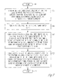
- FIG. 7 is a flow diagram of a method of fabricating an interposer comprising an embedded capacitor, in accordance with an embodiment of the invention.
- FIG. 8 is a flow diagram of a method of fabricating an electronic assembly having an interposer comprising an embedded capacitor, in accordance with an embodiment of the invention.
- the inventive subject matter provides a solution to power delivery problems that are associated with prior art packaging of integrated circuits that operate at high clock speeds and high power levels by embedding one or more decoupling capacitors in a multilayer structure.
- the multilayer structure takes the form of an “interposer” between an IC die and a substrate to which the die would ordinarily have been directly mounted.
- the embedded capacitors can be discrete capacitors, or they can be one or more layers of capacitive material.
- FIG. 1 is a block diagram of an electronic system 1 incorporating at least one electronic assembly 4 with embedded capacitors in accordance with an embodiment of the invention.
- Electronic system 1 is merely one example of an electronic system in which the inventive subject matter can be used.
- electronic system 1 comprises a data processing system that includes a system bus 2 to couple the various components of the system.
- System bus 2 provides communications links among the various components of the electronics system 1 and can be implemented as a single bus, as a combination of busses, or in any other suitable manner.
- Electronic assembly 4 is coupled to system bus 2 .
- Electronic assembly 4 can include any circuit or combination of circuits.
- electronic assembly 4 includes a processor 6 which can be of any type.
- processor means any type of computational circuit, such as but not limited to a microprocessor, a microcontroller, a complex instruction set computing (CISC) microprocessor, a reduced instruction set computing (RISC) microprocessor, a very long instruction word (VLIW) microprocessor, a graphics processor, a digital signal processor (DSP), or any other type of processor or processing circuit.
- CISC complex instruction set computing
- RISC reduced instruction set computing
- VLIW very long instruction word
- DSP digital signal processor
- circuits that could be included in electronic assembly 4 are a custom circuit, an application-specific integrated circuit (ASIC), or the like, such as, for example, one or more circuits (such as communications circuit 7 ) for use in wireless devices like cellular telephones, pagers, portable computers, two-way radios, and similar electronic systems.
- ASIC application-specific integrated circuit
- the IC can perform any other type of function.
- Electronic system 1 can also include an external memory 10 , which in turn can include one or more memory elements suitable to the particular application, such as a main memory 12 in the form of random access memory (RAM), one or more hard drives 14 , and/or one or more drives that handle removable media 16 such as floppy diskettes, compact disks (CDs), digital video disk (DVD), and the like.
- a main memory 12 in the form of random access memory (RAM)
- hard drives 14 a hard drives
- removable media 16 such as floppy diskettes, compact disks (CDs), digital video disk (DVD), and the like.
- Electronic system 1 can also include a display device 8 , a loudspeaker 9 , and a keyboard and/or controller 20 , which can include a mouse, trackball, game controller, voice-recognition device, or any other device that permits a system user to input information into and/or receive information from electronic system 1 .
- a display device 8 can also include a display device 8 , a loudspeaker 9 , and a keyboard and/or controller 20 , which can include a mouse, trackball, game controller, voice-recognition device, or any other device that permits a system user to input information into and/or receive information from electronic system 1 .
- a keyboard and/or controller 20 which can include a mouse, trackball, game controller, voice-recognition device, or any other device that permits a system user to input information into and/or receive information from electronic system 1 .
- FIG. 2 shows a cross-sectional representation of a multilayer interposer 50 in accordance with an embodiment of the invention.
- Interposer 50 is interposed between IC die 40 and primary substrate 60 .
- IC die 40 can be of any type, such as a microprocessor or microcontroller, memory circuit, application specific integrated circuit (ASIC), digital signal processor (DSP), a radio frequency circuit, an amplifier, a power converter, a filter, a clocking circuit, and the like.
- Primary substrate 60 can be of any suitable type and can be made of any suitable material, e.g. an organic material, a polyimide, silicon, glass, quartz, ceramic, and the like.
- Interposer 50 contains at least one embedded capacitor 55 , comprising, in the embodiment shown, alternating pairs of capacitive plates 52 and 54 with high permittivity (Dk) layers 53 between them.
- high permittivity layer means a layer of high permittivity material such as a high permittivity ceramic ply such as titanate particles; a high permittivity dielectric film such as a titanate film that is deposited, for example, by Sol-Gel or metal-organic chemical vapor deposition (MOCVD) techniques; or a layer of any other type of high permittivity material.
- Vcc and Vss electrodes of capacitor 55 of interposer 50 can be coupled by metallized power vias 48 and 49 , respectively, to the corresponding bumps 43 and 45 , respectively, at the central or core region of the die and to corresponding bumps 63 and 65 , respectively, on the primary substrate 60 .
- the via pitch is approximately 150 microns, a large number of such power vias (in excess of 2,000) can be accommodated, coupling capacitor 55 directly to the Vcc and Vss power nodes or bumps of IC die 40 . This ensures a very low value for the loop inductance and enhances the current carrying capability of the overall IC packaging structure.
- the land/bump pitch of the top of interposer 50 needs to match the bump pitch of die 40
- the land/bump pitch of the bottom of interposer 50 needs to match the pad pitch of primary substrate 60
- the pitch is the same on the top and bottom of interposer 50
- the pitch on the bottom of interposer 50 and on the primary substrate 60 could be relaxed to larger dimensions. That is, in an alternative embodiment the interposer 50 could be used to transform the pitch from a relatively tight die bump pitch to a relatively loose substrate pad pitch.
- Signal bumps such as signal bumps 41 and 47 , are typically routed at the periphery of the die in an arrangement that is, for example, four or more rows deep (only one row being shown on each side of die 40 for the sake of simplicity).
- interposer 50 may use through-vias (e.g. signal vias 46 and 51 ) which route signals from these signal bumps on the die to the opposite surface of interposer 50 .
- Interposer 50 can eventually be coupled to the primary substrate 60 , thus ensuring complete connectivity of the Vcc, Vss, and signal levels between the IC die 40 and the primary substrate 60 .
- inventive subject matter is equally applicable to embodiments where signal traces occur other than at the periphery, and to embodiments where Vcc and Vss traces are provided anywhere on the die.
- all signal I/O levels from signal I/O bumps on the IC die 40 can be coupled through interposer 50 to its opposite surface using through-vias like vias 46 and 51 shown in FIG. 2 .
- Vcc and Vss levels from corresponding bumps on the IC die 40 can be coupled through interposer 50 to its opposite surface using through-vias like 48 and 49 , respectively.
- Interposer 50 has a plurality of contacts or lands 44 on one surface that match corresponding solder balls or bumps 42 , in terms of their pitch and placement, on a surface of IC die 40 .
- interposer 50 has a plurality of contacts or lands 56 on another surface that match corresponding solder balls or bumps 58 on a surface of primary substrate 60 .
- Die 40 and primary substrate 60 can be of any type. Although the embodiment of interposer 50 illustrated in FIG. 2 is described as having the same high density configuration of lands and vias as the IC die 40 and primary substrate 60 , other embodiments could have a configuration of lands and vias of a different density.
- the through-vias can couple lands (e.g. lands 44 and 56 ) on opposite sides of the interposer 50 that have the same pitch, or the through-vias can be fanned out in order to relax the pitch of the lands on the lower surface of interposer 50 .
- the lands 44 of interposer 50 are coupled to solder bumps 42 on IC die 40
- the lands 56 of interposer 50 are coupled to solder bumps 58 on primary substrate 60 .
- At least one Vcc terminal 43 on die 40 is coupled to a via 48 of interposer 50 that couples Vcc potential to layers 52 of capacitor 55 and to Vcc terminal 63 of primary substrate 60 .
- at least one Vss terminal 45 on die 40 is coupled to a via 49 of interposer 50 that couples Vss potential to layers 54 of capacitor 55 and to Vss terminal 65 of primary substrate 60 .
- at least one signal terminal 41 on die 40 is coupled to a through-via 46 that couples an IC signal level to a corresponding signal terminal 61 on primary substrate 60 .
- An additional signal terminal 47 on die 40 is coupled to through-via 51 that couples an additional IC signal level to signal terminal 67 on primary substrate 60 .
- interposer One important purpose of the interposer is to provide relatively high capacitance relatively close to the die in order to reduce the effect of reactive inductive coupling when the IC is operating, particularly at high clock speeds.
- FIG. 3 shows a cross-sectional representation of a multilayer interposer 310 with embedded capacitors in which the vias that couple capacitive layers of like potential are arranged throughout the interior of the interposer in accordance with an embodiment of the invention.
- Interposer 310 can be coupled between IC die 300 and primary substrate 320 .
- Interposer 310 can be coupled to IC die 300 by suitable connectors such as solder balls 301 on a matrix having the same pitch and location as corresponding conductive leads on IC die 300 .
- Solder balls 301 can be affixed to lands 302 and 305 of interposer 310 .
- Lands 302 are intended to be coupled to a Vcc potential, while lands 305 are intended to be coupled to a Vss potential.
- Lands 302 are coupled to capacitive plates 306 , whereas lands 305 are coupled to capacitive plates 307 .
- lands 312 are also coupled to capacitive plates 306 .
- Certain ones of solder balls 311 couple lands 312 to corresponding conductive traces or areas of primary substrate 320 .
- lands 315 are coupled to capacitive plates 307 and to others of solder balls 311 that can be affixed to corresponding conductive traces or areas of primary substrate 320 .
- the various capacitive plates 306 are coupled to lands 302 and 312 , and they are further coupled to each other, by conductive vias such as via 303 .
- the various capacitive plates 307 are coupled to lands 305 and 315 , and they are further coupled to each other, by conductive vias such as via 309 .
- vias that connect capacitive plates of the same potential are dispersed throughout any suitable part of the interior region of interposer ceramic substrate 310 .
- the interposer 310 comprises an embedded capacitor stack, the plates of which can be fabricated by using multiple layers or plys of ceramic film having a high pemmittivity (Dk) (i.e. having a dielectric constant greater than that of silicon dioxide).
- Dk high pemmittivity
- the Vcc and Vss connections are coupled to the plate electrodes of the embedded capacitor stack by connecting the respective lands to the plate electrode using metallized vias through the employment of conventional ceramic substrate technology.
- the capacitor could also be fabricated by using a single layer or multiple layers of thin films which are deposited by techniques such as Sol-Gel, MOCVD, sputtering, or the like.
- the Vcc and Vss bumps on the die can be connected to the electrodes of the capacitors by using metallized vias.
- the signal bumps (not illustrated in FIG. 3 but typically located at the peripheral regions of die 300 ) are routed to the opposing face of interposer 310 by using through-vias (although not shown in FIG. 3 they can be of the type illustrated in FIG. 2 ).
- FIG. 4 shows a cross-sectional representation of a multilayer interposer 410 with an embedded discrete capacitor 430 in accordance with an alternate embodiment of the invention.
- Interposer 410 can be coupled between IC die 400 and primary substrate 420 .
- Interposer 410 comprises an embedded discrete capacitor 430 having one terminal 426 intended to be coupled to Vcc potential and another terminal 428 intended to be coupled to Vss potential.
- Lands 402 of interposer 410 are intended to be at Vcc potential and can be coupled via certain ones of solder balls 401 to corresponding conductive areas (not shown) on IC die 400 .
- lands 403 are intended to be at Vss potential and can be coupled via other solder balls 401 to corresponding areas (not shown) on IC die 400 .
- Lands 402 are coupled to one terminal 426 of embedded capacitor 430 by a route that includes vias 404 , conductive layer 406 , and via 412 . Lands 402 are coupled to lands 408 by a similar routing that includes vias 414 .
- Lands 403 are coupled to another terminal 428 of embedded capacitor 430 by a route that includes vias 405 , conductive layer 407 , and via 413 . Lands 403 are coupled to lands 409 by a similar routing that includes vias 415 .
- Lands 408 and 409 can be coupled to corresponding conductive leads or areas (not shown) on a surface of substrate 420 via solder bumps 411 .
- interposer 410 Various signal routing (not illustrated for the sake of simplicity, but comprising signal areas of IC die 400 , certain solder balls 401 , appropriate lands on interposer 410 , and signal planes and vias within interposer 410 ) can also be provided within interposer 410 , as will be understood by those of ordinary skill.
- Embedded capacitor 430 can be of any suitable type. In an embodiment, it is a ceramic chip capacitor that is fabricated using conventional ceramic chip capacitor technology. While a single capacitor 430 is illustrated, for the sake of simplicity of illustration and description, multiple capacitors could be used in the embodiment illustrated in FIG. 4 .
- FIG. 5 shows a cross-sectional representation of a multilayer interposer 510 with two embedded discrete capacitors 530 and 540 in accordance with an alternate embodiment of the invention.
- Interposer 510 can be coupled between IC die 500 and primary substrate 520 .
- Embedded discrete capacitor 530 has terminals 526 and 532 intended to be coupled to Vcc potential, and it further has terminals 528 and 534 intended to be coupled to Vss potential.
- Lands 502 of interposer 510 are intended to be at Vcc potential and can be coupled via certain ones of solder balls 501 to corresponding conductive areas (not shown) on IC die 500 .
- lands 503 are intended to be at Vss potential and can be coupled via other solder balls 501 to corresponding areas (not shown) on IC die 500 .
- Lands 502 are coupled to one terminal 526 of embedded capacitor 530 by a route that includes vias 504 , conductive layer 506 , and via 512 . Lands 502 are coupled to land 508 by a similar routing that includes via 514 .
- Lands 503 are coupled to another terminal 528 of embedded capacitor 530 by a route that includes vias 505 , conductive layer 507 , and via 513 . Lands 503 are coupled to land 509 by a similar routing that includes via 515 .
- Lands 508 and 509 can be coupled to corresponding conductive leads or areas (not shown) on a surface of substrate 520 via solder bumps 511 .
- Discrete capacitor also has two lower terminals 532 and 534 .
- Terminal 532 is coupled to Vcc on the primary substrate 520 by a routing that includes via 531 , conductive layer 525 , via 535 , land 521 , and one of solder bumps 511 .
- terminal 534 is coupled to Vss on the primary substrate 520 by a routing that includes via 533 , conductive layer 525 , via 537 , land 522 , and one of solder bumps 511 .
- interposer 510 Various signal routing comprising signal areas of IC die 500 (not illustrated for the sake of simplicity), certain solder balls 501 , appropriate lands on interposer 510 such as land 517 , and signal planes and vias within interposer 510 such as via 518 can also be provided within interposer 510 , as will be understood by those of ordinary skill.
- Embedded capacitors 530 and 540 can be of any suitable type. In an embodiment, they are ceramic chip capacitors that are fabricated using conventional ceramic chip capacitor technology. While two capacitors 530 and 540 are illustrated, for the sake of simplicity of illustration and description, a different number of capacitors could be used in the embodiment illustrated in FIG. 5 , including only one capacitor.
- FIGS. 2–5 are merely representational and are not drawn to scale. Certain proportions thereof may be exaggerated, while others may be minimized. FIGS. 2–5 are intended to illustrate various implementations of the inventive subject matter, which can be understood and appropriately carried out by those of ordinary skill in the art.
- Multilayer interposers e.g. interposer 50 , FIG. 2
- HTCC high temperature co-fired ceramic
- HITCE high thermal coefficient of expansion
- multilayer stacks of high Dk ply are used in an embodiment.
- High Dk ply is commercially available for fabricating ceramic chip capacitors, for example.
- Suitable high Dk materials such as titanate particles, can be inserted into the conventional ceramic matrix.
- Multilayer stacks of high Dk ply, such as BaTiO 3 in embodiments of the present invention can provide capacitances as high as 10 ⁇ F/sq. cm., compared to capacitances in the range of only nano-Farads/sq. cm. for low Dk ply.
- a high Dk layer such as a titanate film, e.g. (Ba X Sr 1-X )TiO 3 (BST) or PbZrTiO 3 (PZT) or Ta 2 O 5 or SrTiO 3
- a titanate film e.g. (Ba X Sr 1-X )TiO 3 (BST) or PbZrTiO 3 (PZT) or Ta 2 O 5 or SrTiO 3
- MOCVD metal-organic chemical vapor deposition
- Sol-Gel process in which a sol (i.e., a colloidal suspension of solid particles in a liquid) transforms into a gel due to growth and interconnection of solid particles.
- high Dk material can be embedded at temperature ranges that are compatible with ceramic technology (e.g. 600–1000 degrees Centigrade).
- access to the capacitor(s) can be made by any conventional technique, such as punching or laser ablation, and the Vcc and Vss conductors of the interposer can be coupled to the appropriate terminals of the capacitor(s) by any suitable metallization technique that is consistent with the temperature requirements of the process.
- Capacitance values for the embodiment shown in FIG. 2 can be estimated via Equation 1.
- C A * ⁇ r * ⁇ 0 /d Equation (1)
- A capacitor size (square meters)
- FIG. 6 summarizes the approximate range of capacitance available with the various titanates and oxide materials indicated.
- high permittivity ceramic ply such as BaTiO 3 impregnated ceramic ply
- the indicated values correspond to the maximum capacitance generally achievable with a 10 micron thick ply between Vcc and Vss layers in a stack containing 40 such layers.
- the computed values correspond to a 0.25 micron film of the indicated dielectric.
- FIG. 7 is a flow diagram of a method of fabricating an interposer comprising an embedded capacitor, in accordance with an embodiment of the invention. The method begins at 701 .
- At least one capacitor having first and second terminals is formed within a structure.
- the structure is a multilayer ceramic structure, although in other embodiments the structure could be formed of a material other than a ceramic material.
- the capacitor comprises (1) at least one high permittivity layer sandwiched between conductive layers; alternatively, the capacitor is (2) a discrete capacitor.
- first and second power supply nodes are formed in the structure.
- the term “power supply node” refers to either a ground node (e.g. Vss) or to a power node at a potential different from ground (e.g. Vcc).
- a first plurality of lands are formed on a first surface of the structure, including a first land coupled to the first terminal(s) of the capacitor(s) and to the first power supply node, and a second land coupled to the second terminal(s) of the capacitor(s) and to the second power supply node.
- the first and second lands are positioned to be coupled to first and second power supply nodes of a die (e.g. IC die 40 , FIG. 2 ) that is to be juxtaposed to the first surface of the structure.
- a second plurality of lands are formed on a second surface of the structure, including a third land coupled to the first terminal(s) of the capacitor(s) and to the first power supply node, and a fourth land coupled to the second terminal(s) of the capacitor(s) and to the second power supply node.
- the third and fourth lands are positioned to be coupled to first and second power supply nodes of a substrate (e.g. substrate 60 , FIG. 2 ) that is to be juxtaposed to the second surface of the structure.
- the method ends at 711 .
- FIG. 8 is a flow diagram of a method of fabricating an electronic assembly having an interposer comprising an embedded capacitor, in accordance with an embodiment of the invention. The method begins at 801 .
- a die is provided that has first and second power supply nodes.
- a substrate is provided that has third and fourth power supply nodes.
- an interposer is provided to couple the die to the substrate.
- the interposer comprises at least one capacitor having first and second terminals.
- the capacitor comprises (1) at least one high permittivity layer sandwiched between conductive layers; alternatively, the capacitor is a discrete capacitor.
- the interposer further comprises a first plurality of lands on a first surface thereof, including a first land coupled to the first terminal(s) of the capacitor(s) and a second land coupled to the second terminal(s) of the capacitor(s).
- the interposer also comprises a second plurality of lands on a second surface thereof, including a third land coupled to the first terminal(s) and a fourth land coupled to the second terminal(s).
- the first and second lands are coupled to the first and second power supply nodes, respectively, of the die.
- the third and fourth lands are coupled to the third and fourth power supply nodes, respectively, of the substrate.
- Embodiments of the inventive subject matter provide for an electronic assembly and methods of manufacture thereof that minimize problems, such as switching noise, associated with high clock frequencies and high power delivery.
- Embodiments of the inventive subject matter provide scalable high capacitance (e.g. >10 mF/square centimeter) by employing embedded decoupling capacitors having low inductance that can satisfy the power delivery requirements of, for example, high performance processors.
- An electronic system that incorporates the inventive subject matter can operate at higher clock frequencies and is therefore more commercially attractive.
- the inventive subject matter can be implemented in a number of different embodiments, including an interposer, an electronic assembly, an electronic system, a data processing system, a method for making an interposer, and a method of making an electronic assembly.
- Other embodiments will be readily apparent to those of ordinary skill in the art.
- the capacitive elements, choice of materials, geometries, and capacitances can all be varied to suit particular packaging requirements.
- the particular geometry of the embedded capacitors is very flexible in terms of their orientation, size, number, location, and composition of their constituent elements.
- inventive subject matter is not to be construed as limited to use in C4 packages, and it can be used with any other type of IC package where the herein-described features of the inventive subject matter provide an advantage.
Abstract
To reduce switching noise, the power supply terminals of an integrated circuit die are coupled to the respective terminals of at least one capacitor embedded in an interposer that lies between the die and a substrate. In an embodiment, the interposer is a multilayer ceramic structure that couples power and signal conductors on the die to corresponding conductors on the substrate. The capacitor is formed of at least one high permittivity layer and in an embodiment comprises several high permittivity layers interleaved with conductive layers. Alternatively, the capacitor can comprise at least one embedded discrete capacitor. Also described are an electronic system, a data processing system, and various methods of manufacture.
Description
The present application is related to the following application which is assigned to the same assignee as the present application and which was filed on even date herewith:
Ser. No. 09/631,037, entitled “Electronic Assembly Comprising Substrate with Embedded Capacitors”, now U.S. Pat. No. 6,611,419.
The application relates generally to electronics packaging. More particularly, the application relates to an electronic assembly that includes an interposer having one or more embedded capacitors to reduce switching noise in a high-speed integrated circuit, and to manufacturing methods related thereto.
Integrated circuits (ICs) are typically assembled into packages by physically and electrically coupling them to a substrate made of organic or ceramic material. One or more IC packages can be physically and electrically coupled to a printed circuit board (PCB) or card to form an “electronic assembly”. The “electronic assembly” can be part of an “electronic system”. An “electronic system” is broadly defined herein as any product comprising an “electronic assembly”. Examples of electronic systems include computers (e.g., desktop, laptop, hand-held, server, etc.), wireless communications devices (e.g., cellular phones, cordless phones, pagers, etc.), computer-related peripherals (e.g., printers, scanners, monitors, etc.), entertainment devices (e.g., televisions, radios, stereos, tape and compact disc players, video cassette recorders, MP3 (Motion Picture Experts Group, Audio Layer 3) players, etc.), and the like.
In the field of electronic systems there is an incessant competitive pressure among manufacturers to drive the performance of their equipment up while driving down production costs. This is particularly true regarding the packaging of ICs on substrates, where each new generation of packaging must provide increased performance while generally being smaller or more compact in size.
An IC substrate may comprise a number of insulated metal layers selectively patterned to provide metal interconnect lines (referred to herein as “traces”), and one or more electronic components mounted on one or more surfaces of the substrate. The electronic component or components are functionally connected to other elements of an electronic system through a hierarchy of conductive paths that includes the substrate traces. The substrate traces typically carry signals that are transmitted between the electronic components, such as ICs, of the system. Some ICs have a relatively large number of input/output (I/O) terminals, as well as a large number of power and ground terminals. The large number of I/O, power, and ground terminals requires that the substrate contain a relatively large number of traces. Some substrates require multiple layers of traces to accommodate all of the system interconnections.
Traces located within different layers are typically connected electrically by vias (also called “plated through-holes”) formed in the board. A via can be made by making a hole through some or all layers of a substrate and then plating the interior hole surface or filling the hole with an electrically conductive material, such as copper or tungsten.
One of the conventional methods for mounting an IC on a substrate is called “controlled collapse chip connect” (C4). In fabricating a C4 package, the electrically conductive terminations or lands (generally referred to as “electrical contacts”) of an IC component are soldered directly to corresponding lands on the surface of the substrate using reflowable solder bumps or balls. The C4 process is widely used because of its robustness and simplicity.
As the internal circuitry of ICs, such as processors, operates at higher and higher clock frequencies, and as ICs operate at higher and higher power levels, switching noise can increase to unacceptable levels.
For the reasons stated above, and for other reasons stated below which will become apparent to those skilled in the art upon reading and understanding the present specification, there is a significant need in the art for a method and apparatus for packaging an IC on a substrate that minimizes problems, such as switching noise, associated with high clock frequencies and high power delivery.
In the following detailed description of embodiments of the invention, reference is made to the accompanying drawings that form a part hereof, and in which is shown by way of illustration specific preferred embodiments in which the inventive subject matter may be practiced. These embodiments are described in sufficient detail to enable those skilled in the art to practice the inventive subject matter, and it is to be understood that other embodiments may be utilized and that logical, mechanical and electrical changes may be made without departing from the spirit and scope of the present inventive subject matter. The following detailed description is, therefore, not to be taken in a limiting sense, and the scope of embodiments of the inventive subject matter is defined only by the appended claims.
The inventive subject matter provides a solution to power delivery problems that are associated with prior art packaging of integrated circuits that operate at high clock speeds and high power levels by embedding one or more decoupling capacitors in a multilayer structure. Various embodiments are illustrated and described herein. In an embodiment, the multilayer structure takes the form of an “interposer” between an IC die and a substrate to which the die would ordinarily have been directly mounted. The embedded capacitors can be discrete capacitors, or they can be one or more layers of capacitive material.
Other types of circuits that could be included in electronic assembly 4 are a custom circuit, an application-specific integrated circuit (ASIC), or the like, such as, for example, one or more circuits (such as communications circuit 7) for use in wireless devices like cellular telephones, pagers, portable computers, two-way radios, and similar electronic systems. The IC can perform any other type of function.
The Vcc and Vss electrodes of capacitor 55 of interposer 50, represented by reference numerals 52 and 54, respectively, can be coupled by metallized power vias 48 and 49, respectively, to the corresponding bumps 43 and 45, respectively, at the central or core region of the die and to corresponding bumps 63 and 65, respectively, on the primary substrate 60. If it is assumed, for the embodiment illustrated, that the via pitch is approximately 150 microns, a large number of such power vias (in excess of 2,000) can be accommodated, coupling capacitor 55 directly to the Vcc and Vss power nodes or bumps of IC die 40. This ensures a very low value for the loop inductance and enhances the current carrying capability of the overall IC packaging structure.
It will be understood that the land/bump pitch of the top of interposer 50 needs to match the bump pitch of die 40, and that the land/bump pitch of the bottom of interposer 50 needs to match the pad pitch of primary substrate 60. While in the embodiment shown in FIG. 2 the pitch is the same on the top and bottom of interposer 50, the pitch on the bottom of interposer 50 and on the primary substrate 60 could be relaxed to larger dimensions. That is, in an alternative embodiment the interposer 50 could be used to transform the pitch from a relatively tight die bump pitch to a relatively loose substrate pad pitch.
Signal bumps, such as signal bumps 41 and 47, are typically routed at the periphery of the die in an arrangement that is, for example, four or more rows deep (only one row being shown on each side of die 40 for the sake of simplicity). For peripheral signal bumps, interposer 50 may use through-vias (e.g. signal vias 46 and 51) which route signals from these signal bumps on the die to the opposite surface of interposer 50. Interposer 50 can eventually be coupled to the primary substrate 60, thus ensuring complete connectivity of the Vcc, Vss, and signal levels between the IC die 40 and the primary substrate 60.
The inventive subject matter is equally applicable to embodiments where signal traces occur other than at the periphery, and to embodiments where Vcc and Vss traces are provided anywhere on the die. Essentially, all signal I/O levels from signal I/O bumps on the IC die 40 can be coupled through interposer 50 to its opposite surface using through-vias like vias 46 and 51 shown in FIG. 2 . Likewise, Vcc and Vss levels from corresponding bumps on the IC die 40 can be coupled through interposer 50 to its opposite surface using through-vias like 48 and 49, respectively.
When the IC package is assembled, the lands 44 of interposer 50 are coupled to solder bumps 42 on IC die 40, and the lands 56 of interposer 50 are coupled to solder bumps 58 on primary substrate 60.
At least one Vcc terminal 43 on die 40 is coupled to a via 48 of interposer 50 that couples Vcc potential to layers 52 of capacitor 55 and to Vcc terminal 63 of primary substrate 60. Also, at least one Vss terminal 45 on die 40 is coupled to a via 49 of interposer 50 that couples Vss potential to layers 54 of capacitor 55 and to Vss terminal 65 of primary substrate 60. In addition, at least one signal terminal 41 on die 40 is coupled to a through-via 46 that couples an IC signal level to a corresponding signal terminal 61 on primary substrate 60. An additional signal terminal 47 on die 40 is coupled to through-via 51 that couples an additional IC signal level to signal terminal 67 on primary substrate 60.
One important purpose of the interposer is to provide relatively high capacitance relatively close to the die in order to reduce the effect of reactive inductive coupling when the IC is operating, particularly at high clock speeds.
Also coupled to capacitive plates 306 are lands 312 on another surface of interposer 310. Certain ones of solder balls 311 couple lands 312 to corresponding conductive traces or areas of primary substrate 320. In addition, lands 315 are coupled to capacitive plates 307 and to others of solder balls 311 that can be affixed to corresponding conductive traces or areas of primary substrate 320.
In this embodiment, the various capacitive plates 306 are coupled to lands 302 and 312, and they are further coupled to each other, by conductive vias such as via 303. Likewise, the various capacitive plates 307 are coupled to lands 305 and 315, and they are further coupled to each other, by conductive vias such as via 309. In this embodiment, vias that connect capacitive plates of the same potential are dispersed throughout any suitable part of the interior region of interposer ceramic substrate 310.
The interposer 310 comprises an embedded capacitor stack, the plates of which can be fabricated by using multiple layers or plys of ceramic film having a high pemmittivity (Dk) (i.e. having a dielectric constant greater than that of silicon dioxide). The Vcc and Vss connections are coupled to the plate electrodes of the embedded capacitor stack by connecting the respective lands to the plate electrode using metallized vias through the employment of conventional ceramic substrate technology.
Alternatively, the capacitor could also be fabricated by using a single layer or multiple layers of thin films which are deposited by techniques such as Sol-Gel, MOCVD, sputtering, or the like.
As described above, the Vcc and Vss bumps on the die can be connected to the electrodes of the capacitors by using metallized vias. The signal bumps (not illustrated in FIG. 3 but typically located at the peripheral regions of die 300) are routed to the opposing face of interposer 310 by using through-vias (although not shown in FIG. 3 they can be of the type illustrated in FIG. 2 ).
Various signal routing (not illustrated for the sake of simplicity, but comprising signal areas of IC die 400, certain solder balls 401, appropriate lands on interposer 410, and signal planes and vias within interposer 410) can also be provided within interposer 410, as will be understood by those of ordinary skill.
Embedded capacitor 430 can be of any suitable type. In an embodiment, it is a ceramic chip capacitor that is fabricated using conventional ceramic chip capacitor technology. While a single capacitor 430 is illustrated, for the sake of simplicity of illustration and description, multiple capacitors could be used in the embodiment illustrated in FIG. 4 .
Embedded discrete capacitor 530 has terminals 526 and 532 intended to be coupled to Vcc potential, and it further has terminals 528 and 534 intended to be coupled to Vss potential.
Discrete capacitor also has two lower terminals 532 and 534. Terminal 532 is coupled to Vcc on the primary substrate 520 by a routing that includes via 531, conductive layer 525, via 535, land 521, and one of solder bumps 511. Likewise, terminal 534 is coupled to Vss on the primary substrate 520 by a routing that includes via 533, conductive layer 525, via 537, land 522, and one of solder bumps 511.
Various signal routing comprising signal areas of IC die 500 (not illustrated for the sake of simplicity), certain solder balls 501, appropriate lands on interposer 510 such as land 517, and signal planes and vias within interposer 510 such as via 518 can also be provided within interposer 510, as will be understood by those of ordinary skill.
Embedded capacitors 530 and 540 can be of any suitable type. In an embodiment, they are ceramic chip capacitors that are fabricated using conventional ceramic chip capacitor technology. While two capacitors 530 and 540 are illustrated, for the sake of simplicity of illustration and description, a different number of capacitors could be used in the embodiment illustrated in FIG. 5 , including only one capacitor.
Multilayer interposers (e.g. interposer 50, FIG. 2 ) can be fabricated by conventional techniques, such as but not limited to high temperature co-fired ceramic (HTCC) technology, high thermal coefficient of expansion (HITCE) technology, or glass ceramic technology.
Although it is known in ceramic technology to embed low Dk capacitors in ceramic substrates, by sandwiching thin (e.g. 2 mils) films of conventional ceramic such as Al2O3 between metal planes, in embodiments of the present invention multilayer stacks of high Dk ply are used in an embodiment. High Dk ply is commercially available for fabricating ceramic chip capacitors, for example. Suitable high Dk materials, such as titanate particles, can be inserted into the conventional ceramic matrix. Multilayer stacks of high Dk ply, such as BaTiO3, in embodiments of the present invention can provide capacitances as high as 10 μF/sq. cm., compared to capacitances in the range of only nano-Farads/sq. cm. for low Dk ply.
In an alternative embodiment, a high Dk layer, such as a titanate film, e.g. (BaXSr1-X)TiO3 (BST) or PbZrTiO3 (PZT) or Ta2O5 or SrTiO3, can be formed in the ceramic substrate by known techniques such as a metal-organic chemical vapor deposition (MOCVD) process, or a Sol-Gel process, in which a sol (i.e., a colloidal suspension of solid particles in a liquid) transforms into a gel due to growth and interconnection of solid particles.
In either case, high Dk material can be embedded at temperature ranges that are compatible with ceramic technology (e.g. 600–1000 degrees Centigrade).
Regarding the embodiments illustrated in FIGS. 4 and 5 , wherein one or more discrete capacitors are embedded in the interposer, access to the capacitor(s) can be made by any conventional technique, such as punching or laser ablation, and the Vcc and Vss conductors of the interposer can be coupled to the appropriate terminals of the capacitor(s) by any suitable metallization technique that is consistent with the temperature requirements of the process.
Capacitance values for the embodiment shown in FIG. 2 can be estimated via Equation 1.
C=A*εr*ε0 /d Equation (1)
where: A=capacitor size (square meters)
C=A*εr*ε0 /d Equation (1)
where: A=capacitor size (square meters)
-
- εr=permittivity constant 8.854×10⁻¹² Farads/meter
- ε0=dielectric constant of insulator
- d=dielectric layer thickness (meters)
In the case of a dielectric formed by Sol-Gel or MOCVD embodiments (e.g., PZT, BST, SrTiO3, or Ta2O5), the computed values correspond to a 0.25 micron film of the indicated dielectric.
To satisfy the capacitance requirements of any given embodiment, multiple layers of capacitors could be stacked as necessary.
In 703, at least one capacitor having first and second terminals is formed within a structure. In an embodiment, the structure is a multilayer ceramic structure, although in other embodiments the structure could be formed of a material other than a ceramic material. The capacitor comprises (1) at least one high permittivity layer sandwiched between conductive layers; alternatively, the capacitor is (2) a discrete capacitor.
In 705, first and second power supply nodes are formed in the structure. As used herein, the term “power supply node” refers to either a ground node (e.g. Vss) or to a power node at a potential different from ground (e.g. Vcc).
In 707, a first plurality of lands are formed on a first surface of the structure, including a first land coupled to the first terminal(s) of the capacitor(s) and to the first power supply node, and a second land coupled to the second terminal(s) of the capacitor(s) and to the second power supply node. The first and second lands are positioned to be coupled to first and second power supply nodes of a die (e.g. IC die 40, FIG. 2 ) that is to be juxtaposed to the first surface of the structure.
In 709, a second plurality of lands are formed on a second surface of the structure, including a third land coupled to the first terminal(s) of the capacitor(s) and to the first power supply node, and a fourth land coupled to the second terminal(s) of the capacitor(s) and to the second power supply node. The third and fourth lands are positioned to be coupled to first and second power supply nodes of a substrate (e.g. substrate 60, FIG. 2 ) that is to be juxtaposed to the second surface of the structure. The method ends at 711.
In 803, a die is provided that has first and second power supply nodes.
In 805, a substrate is provided that has third and fourth power supply nodes.
In 807, an interposer is provided to couple the die to the substrate. The interposer comprises at least one capacitor having first and second terminals. The capacitor comprises (1) at least one high permittivity layer sandwiched between conductive layers; alternatively, the capacitor is a discrete capacitor. The interposer further comprises a first plurality of lands on a first surface thereof, including a first land coupled to the first terminal(s) of the capacitor(s) and a second land coupled to the second terminal(s) of the capacitor(s). The interposer also comprises a second plurality of lands on a second surface thereof, including a third land coupled to the first terminal(s) and a fourth land coupled to the second terminal(s).
In 809, the first and second lands are coupled to the first and second power supply nodes, respectively, of the die.
In 811, the third and fourth lands are coupled to the third and fourth power supply nodes, respectively, of the substrate.
The operations described above with respect to the methods illustrated in FIGS. 7 and 8 can be performed in a different order from those described herein.
Embodiments of the inventive subject matter provide for an electronic assembly and methods of manufacture thereof that minimize problems, such as switching noise, associated with high clock frequencies and high power delivery. Embodiments of the inventive subject matter provide scalable high capacitance (e.g. >10 mF/square centimeter) by employing embedded decoupling capacitors having low inductance that can satisfy the power delivery requirements of, for example, high performance processors. An electronic system that incorporates the inventive subject matter can operate at higher clock frequencies and is therefore more commercially attractive.
As shown herein, the inventive subject matter can be implemented in a number of different embodiments, including an interposer, an electronic assembly, an electronic system, a data processing system, a method for making an interposer, and a method of making an electronic assembly. Other embodiments will be readily apparent to those of ordinary skill in the art. The capacitive elements, choice of materials, geometries, and capacitances can all be varied to suit particular packaging requirements. The particular geometry of the embedded capacitors is very flexible in terms of their orientation, size, number, location, and composition of their constituent elements.
While embodiments have been shown in which signal traces are provided around the periphery, and in which Vcc and Vss traces are provided at the die core, the inventive subject matter is equally applicable to embodiments where the signal traces occur other than at the periphery, and to embodiments where Vcc and Vss traces are provided anywhere on the die.
Further, the inventive subject matter is not to be construed as limited to use in C4 packages, and it can be used with any other type of IC package where the herein-described features of the inventive subject matter provide an advantage.
Although specific embodiments have been illustrated and described herein, it will be appreciated by those of ordinary skill in the art that any arrangement that is calculated to achieve the same purpose may be substituted for the specific embodiment shown. This application is intended to cover any adaptations or variations of the inventive subject matter. Therefore, it is manifestly intended that embodiments of this invention be limited only by the claims and the equivalents thereof.
Claims (24)
1. An interposer to couple a die to a substrate and comprising:
a plurality of power and ground vias in a core region of the interposer;
a plurality of signal vias in a peripheral region of the interposer;
an embedded capacitor having first and second terminals;
a first surface including a first plurality of power lands coupled to the first terminal through first ones of the plurality of power vias, and a first plurality of ground lands coupled to the second terminal through first ones of the plurality of ground vias; and
a second surface including a second plurality of power lands coupled to the first terminal through second ones of the plurality of power vias, and a second plurality of ground lands coupled to the second terminal through second ones of the plurality of ground vias;
wherein the first plurality of power lands and the first plurality of ground lands are positioned to be coupled to corresponding power and ground nodes of the die through controlled collapse chip connect solder bumps;
wherein the first surface comprises a first plurality of signal lands coupled to the plurality of signal vias and positioned to be coupled to corresponding signal nodes of the die; and
wherein the second surface comprises a second plurality of signal lands coupled to the plurality of signal vias and positioned to be coupled to corresponding signal nodes of the substrate.
2. The interposer recited in claim 1 wherein the second plurality of power lands and the second plurality of ground lands are positioned to be coupled to corresponding power and ground nodes of the substrate.
3. The interposer recited in claim 1 wherein the capacitor comprises at least one high permittivity layer.
4. The interposer recited in claim 1 wherein the capacitor comprises a plurality of high permittivity layers.
5. The interposer recited in claim 1 , wherein the interposer comprises a multilayer ceramic structure.
6. The interposer recited in claim 1 , wherein at least one of the power vias does not go entirely through the interposer.
7. The interposer recited in claim 1 , wherein at least one of the ground vias does not go entirely through the interposer.
8. The interposer recited in claim 1 , wherein the plurality of power and ground vias is a relatively large number.
9. The interposer recited in claim 4 wherein the capacitor comprises a plurality of conductive layers interleaved with the high permittivity layers, such that alternating conductive layers are coupled to the first and second terminals, respectively.
10. An electronic assembly comprising:
a die comprising a first plurality of power nodes and a first plurality of ground nodes;
a substrate comprising a second plurality of power nodes and a second plurality of ground nodes; and
an interposer coupling the die to the substrate and including a plurality of power and ground vias in a core region of the interposer;
a plurality of signal vias in a peripheral region of the interposer;
an embedded capacitor having a first terminal and a second terminal;
a first surface including a first plurality of power lands coupled to the first terminal through first ones of the plurality of power vias, and a first plurality of ground lands coupled to the second terminal through first ones of the plurality of ground vias; and
a second surface including a second plurality of power lands coupled to the first terminal through second ones of the plurality of power vias, and a second plurality of ground lands coupled to the second terminal through second ones of the plurality of ground vias;
wherein the first plurality of power lands and the first plurality of ground lands are coupled to the respective first plurality of power nodes and first plurality of ground nodes of the die, and
wherein the second plurality of power lands and the second plurality of ground lands are coupled to the respective second plurality of power nodes and second plurality of ground nodes of the substrate;
wherein the first surface comprises a first plurality of signal lands coupled to the plurality of signal vias and positioned to be coupled to corresponding signal nodes of the die; and
wherein the second surface comprises a second plurality of signal lands coupled to the plurality of signal vias and positioned to be coupled to corresponding signal nodes of the substrate.
11. The electronic assembly recited in claim 10 wherein the capacitor comprises a plurality of high permittivity layers.
12. The electronic assembly recited in claim 11 wherein the capacitor comprises a plurality of conductive layers interleaved with the high permittivity layers, such that alternating conductive layers are coupled to the first and second terminals, respectively.
13. An electronic system comprising an electronic assembly comprising:
a die comprising a first plurality of power nodes and a first plurality of ground nodes;
a substrate comprising a second plurality of power nodes and a second plurality of ground nodes; and
an interposer coupling the die to the substrate and including
a plurality of power and ground vias in a core region of the interposer;
a plurality of signal vias in a peripheral region of the interposer;
an embedded capacitor having a first terminal and a second terminal;
a first surface including a first plurality of power lands coupled to the first terminal through first ones of the plurality of power vias, and a first plurality of ground lands coupled to the second terminal through first ones of the plurality of ground vias; and
a second surface including a second plurality of power lands coupled to the first terminal through second ones of the plurality of power vias, and a second plurality of ground lands coupled to the second terminal through second ones of the plurality of ground vias;
wherein the first plurality of power lands and the first plurality of ground lands are coupled to the respective first plurality of power nodes and first plurality of ground nodes of the die;
wherein the second plurality of power lands and the second plurality of ground lands are coupled to the respective second plurality of power nodes and second plurality of ground nodes of the substrate;
wherein the first surface comprises a first plurality of signal lands coupled to the plurality of signal vias and positioned to be coupled to corresponding signal nodes of the die; and
wherein the second surface comprises a second plurality of signal lands coupled to the plurality of signal vias and positioned to be coupled to corresponding signal nodes of the substrate.
14. The electronic system recited in claim 13 wherein the capacitor comprises a plurality of high permittivity layers.
15. The electronic system recited in claim 14 wherein the capacitor comprises a plurality of conductive layers interleaved with the high permittivity layers, such that alternating conductive layers are coupled to the first and second terminals, respectively.
16. An interposer to couple a die to a substrate and comprising:
a plurality of power and ground vias in a core region of the interposer;
an embedded capacitor having a first terminal and a second terminal;
a first surface including a first plurality of power lands coupled to the first terminal through the plurality of power vias, and a first plurality of ground lands coupled to the second terminal through the plurality of ground vias; and
a second surface including a second plurality of power lands coupled to the first terminal through the plurality of power vias, and a second plurality of ground lands coupled to the second terminal through the plurality of ground vias;
wherein the first plurality of power lands and the first plurality of ground lands are positioned to be coupled to corresponding power and ground nodes of the die through controlled collapse chip connect solder bumps.
17. The interposer recited in claim 16 wherein the second plurality of power lands and the second plurality of ground lands are positioned to be coupled to corresponding power and ground nodes of the substrate.
18. The interposer recited in claim 16 wherein the capacitor comprises at least one high permittivity layer.
19. The interposer recited in claim 16 wherein the capacitor comprises a plurality of high permittivity layers.
20. The interposer recited in claim 16 , wherein the interposer comprises a multilayer ceramic structure.
21. The interposer recited in claim 16 , wherein at least one of the power vias does not go entirely through the interposer.
22. The interposer recited in claim 16 , wherein at least one of the ground vias does not go entirely through the interposer.
23. The interposer recited in claim 16 , wherein the plurality of power and ground vias is a relatively large number.
24. The interposer recited in claim 19 wherein the capacitor comprises a plurality of conductive layers interleaved with the high permittivity layers, such that alternating conductive layers are coupled to the first and second terminals, respectively.
Priority Applications (9)
| Application Number | Priority Date | Filing Date | Title |
|---|---|---|---|
| US09/628,705 US6970362B1 (en) | 2000-07-31 | 2000-07-31 | Electronic assemblies and systems comprising interposer with embedded capacitors |
| MYPI20012942A MY136263A (en) | 2000-07-31 | 2001-06-21 | Electronic assemblies and systems comprising interposer with embedded capacitors |
| MYPI20013021 MY133591A (en) | 2000-07-31 | 2001-06-26 | Electronic assembly comprising substrate with embedded capacitors |
| AU2001280849A AU2001280849A1 (en) | 2000-07-31 | 2001-07-26 | Electronic assembly comprising interposer with embedded capacitors and methods of manufacture |
| PCT/US2001/023719 WO2002011206A2 (en) | 2000-07-31 | 2001-07-26 | Electronic assembly comprising interposer with embedded capacitors and methods of manufacture |
| CNB018136389A CN100492629C (en) | 2000-07-31 | 2001-07-26 | Electronic assembly comprising interposer with embedded capacitors and methods of manufacture |
| EP01959276A EP1305830A2 (en) | 2000-07-31 | 2001-07-26 | Electronic assembly comprising interposer with embedded capacitors and methods of manufacture |
| HK03104453.9A HK1052252A1 (en) | 2000-07-31 | 2003-06-20 | Electronic assembly comprising interposer with embedded capacitors and methods of manufacture |
| US11/222,320 US7339798B2 (en) | 2000-07-31 | 2005-09-08 | Electronic assemblies and systems comprising interposer with embedded capacitors |
Applications Claiming Priority (1)
| Application Number | Priority Date | Filing Date | Title |
|---|---|---|---|
| US09/628,705 US6970362B1 (en) | 2000-07-31 | 2000-07-31 | Electronic assemblies and systems comprising interposer with embedded capacitors |
Related Child Applications (1)
| Application Number | Title | Priority Date | Filing Date |
|---|---|---|---|
| US11/222,320 Continuation US7339798B2 (en) | 2000-07-31 | 2005-09-08 | Electronic assemblies and systems comprising interposer with embedded capacitors |
Publications (1)
| Publication Number | Publication Date |
|---|---|
| US6970362B1 true US6970362B1 (en) | 2005-11-29 |
Family
ID=24519977
Family Applications (2)
| Application Number | Title | Priority Date | Filing Date |
|---|---|---|---|
| US09/628,705 Expired - Lifetime US6970362B1 (en) | 2000-07-31 | 2000-07-31 | Electronic assemblies and systems comprising interposer with embedded capacitors |
| US11/222,320 Expired - Lifetime US7339798B2 (en) | 2000-07-31 | 2005-09-08 | Electronic assemblies and systems comprising interposer with embedded capacitors |
Family Applications After (1)
| Application Number | Title | Priority Date | Filing Date |
|---|---|---|---|
| US11/222,320 Expired - Lifetime US7339798B2 (en) | 2000-07-31 | 2005-09-08 | Electronic assemblies and systems comprising interposer with embedded capacitors |
Country Status (7)
| Country | Link |
|---|---|
| US (2) | US6970362B1 (en) |
| EP (1) | EP1305830A2 (en) |
| CN (1) | CN100492629C (en) |
| AU (1) | AU2001280849A1 (en) |
| HK (1) | HK1052252A1 (en) |
| MY (1) | MY136263A (en) |
| WO (1) | WO2002011206A2 (en) |
Cited By (66)
| Publication number | Priority date | Publication date | Assignee | Title |
|---|---|---|---|---|
| US20040043190A1 (en) * | 2002-09-04 | 2004-03-04 | Murata Manufacturing Co., Ltd. | Laminated electronic component |
| US20040231885A1 (en) * | 2003-03-07 | 2004-11-25 | Borland William J. | Printed wiring boards having capacitors and methods of making thereof |
| US20050133903A1 (en) * | 2003-12-23 | 2005-06-23 | Palanduz Cengiz A. | Integrated circuit package substrate having a thin film capacitor structure |
| US20050156279A1 (en) * | 2001-01-26 | 2005-07-21 | Fujitsu Limited | Capacitor and semiconductor device and method for fabricating the semiconductor device |
| US20050161725A1 (en) * | 2002-04-19 | 2005-07-28 | Nicola Da Dalt | Semiconductor component comprising an integrated latticed capacitance structure |
| US20050218502A1 (en) * | 2004-03-31 | 2005-10-06 | Shinko Electric Industries Co., Ltd. | Capacitor-mounted wiring board and method of manufacturing the same |
| US20050230146A1 (en) * | 2003-01-31 | 2005-10-20 | Hideki Koyama | Multilayer printed board, electronic apparatus, and packaging method |
| US20050230812A1 (en) * | 2002-06-25 | 2005-10-20 | Andreas Przadka | Electronic component comprising a multilayer substrate and corresponding method of production |
| US20050263873A1 (en) * | 2004-05-28 | 2005-12-01 | Nec Compound Semiconductor Device, Ltd. | Interposer substrate, semiconductor package and semiconductor device, and their producing methods |
| US20050280137A1 (en) * | 2004-06-17 | 2005-12-22 | Cornelius William P | Method and apparatus for providing wafer-level capacitive decoupling |
| US20050280146A1 (en) * | 2004-06-17 | 2005-12-22 | Cornelius William P | Interposer containing bypass capacitors for reducing voltage noise in an IC device |
| US20050280145A1 (en) * | 2004-06-17 | 2005-12-22 | Cornelius William P | Semiconductor die package with internal bypass capacitors |
| US20060012966A1 (en) * | 2000-07-31 | 2006-01-19 | Intel Corporation | Electronic assemblies and systems comprising interposer with embedded capacitors |
| US20060087024A1 (en) * | 2004-10-26 | 2006-04-27 | Eiichi Hosomi | Method and system for an improved power distribution network for use with a semiconductor device |
| US20060137905A1 (en) * | 2003-12-05 | 2006-06-29 | Ibiden Co., Ltd. | Multilayer printed wiring board |
| US20060220167A1 (en) * | 2005-03-31 | 2006-10-05 | Intel Corporation | IC package with prefabricated film capacitor |
| US7120031B2 (en) | 2000-08-30 | 2006-10-10 | Intel Corporation | Data processing system comprising ceramic/organic hybrid substrate with embedded capacitors |
| US20060237225A1 (en) * | 2003-02-26 | 2006-10-26 | Takashi Kariya | Multilayer printed wiring board |
| US20060289976A1 (en) * | 2005-06-23 | 2006-12-28 | Intel Corporation | Pre-patterned thin film capacitor and method for embedding same in a package substrate |
| US20070001226A1 (en) * | 2005-06-30 | 2007-01-04 | Semiconductor Energy Laboratory Co., Ltd. | Semiconductor device |
| US20070029106A1 (en) * | 2003-04-07 | 2007-02-08 | Ibiden Co., Ltd. | Multilayer printed wiring board |
| US20070102805A1 (en) * | 2005-11-04 | 2007-05-10 | Samsung Electronics Co., Ltd | Chip type electric device and method, and display device including the same |
| US20070158105A1 (en) * | 2005-11-18 | 2007-07-12 | Kohji Kitao | Multilayer wiring board capable of reducing noise over wide frequency band with simple structure |
| US20070210417A1 (en) * | 2005-12-29 | 2007-09-13 | Qimonda Ag | Chip carrier with reduced interference signal sensitivity |
| US20070215962A1 (en) * | 2006-03-20 | 2007-09-20 | Knowles Elecronics, Llc | Microelectromechanical system assembly and method for manufacturing thereof |
| US20070257367A1 (en) * | 2006-05-05 | 2007-11-08 | Tru-Si Technologies, Inc. | Dielectric trenches, nickel/tantalum oxide structures,and chemical mechanical polishing techniques |
| US20070279840A1 (en) * | 2006-05-31 | 2007-12-06 | Xing Jin | Embedded electrolytic capacitor |
| US7327554B2 (en) * | 2003-03-19 | 2008-02-05 | Ngk Spark Plug Co., Ltd. | Assembly of semiconductor device, interposer and substrate |
| US7355836B2 (en) * | 2005-06-07 | 2008-04-08 | Intel Corporation | Array capacitor for decoupling multiple voltage rails |
| US7378733B1 (en) | 2006-08-29 | 2008-05-27 | Xilinx, Inc. | Composite flip-chip package with encased components and method of fabricating same |
| US20080174976A1 (en) * | 2001-07-12 | 2008-07-24 | Hitachi, Ltd. | Electronic Circuit Component |
| US20080247116A1 (en) * | 2007-04-06 | 2008-10-09 | Ibiden Co., Ltd | Interposer, a method for manufacturing the same and an electronic circuit package |
| WO2009042463A1 (en) * | 2007-09-25 | 2009-04-02 | Intel Corporation | Integrated circuit packages including high density bump-less build up layers and a lesser density core or coreless substrate |
| US7566960B1 (en) * | 2003-10-31 | 2009-07-28 | Xilinx, Inc. | Interposing structure |
| US7576995B2 (en) * | 2005-11-04 | 2009-08-18 | Entorian Technologies, Lp | Flex circuit apparatus and method for adding capacitance while conserving circuit board surface area |
| US20090250801A1 (en) * | 2008-04-03 | 2009-10-08 | Elpida Memory, Inc. | Semiconductor device |
| US7605460B1 (en) | 2008-02-08 | 2009-10-20 | Xilinx, Inc. | Method and apparatus for a power distribution system |
| US20100155119A1 (en) * | 2006-11-30 | 2010-06-24 | Matsushita Electric Industrial Co., Ltd. | Passive component incorporating interposer |
| US20100202127A1 (en) * | 2009-02-06 | 2010-08-12 | Tuominen Risto | Electronic module with emi protection |
| US20100244221A1 (en) * | 2009-03-27 | 2010-09-30 | Chan Hoon Ko | Integrated circuit packaging system having dual sided connection and method of manufacture thereof |
| US20100277881A1 (en) * | 2009-05-04 | 2010-11-04 | Russell James V | Embedded components in interposer board for improving power gain (distribution) and power loss (dissipation) in interconnect configuration |
| US20110027945A1 (en) * | 2007-12-27 | 2011-02-03 | Sanyo Electric Co., Ltd. | Substrate for mounting device and method for producing the same, semiconductor module and method for producing the same, and portable apparatus provided with the same |
| WO2012061304A1 (en) * | 2010-11-02 | 2012-05-10 | Georgia Tech Research Corporation | Ultra-thin interposer assemblies with through vias |
| US20140003012A1 (en) * | 2012-07-02 | 2014-01-02 | Samsung Electro-Mechanics Co., Ltd. | Capacitor-embedded printed circuit board |
| US8624365B1 (en) * | 2010-07-23 | 2014-01-07 | Marvell International Ltd. | Interposer based capacitors for semiconductor packaging |
| US8634201B1 (en) * | 2009-12-01 | 2014-01-21 | City Labs, Inc. | Radioisotope power source package for microelectronics |
| US20140204788A1 (en) * | 2012-02-13 | 2014-07-24 | Sentinel Connector Systems, Inc. | Testing apparatus for a high speed communications jack and methods of operating the same |
| US20150162301A1 (en) * | 2013-12-09 | 2015-06-11 | Siliconware Precision Industries Co., Ltd. | Method for fabricating semiconductor package |
| US20150230338A1 (en) * | 2012-10-30 | 2015-08-13 | Intel Corporation | Circuit board with integrated passive devices |
| US20160260795A1 (en) * | 2015-03-03 | 2016-09-08 | Renesas Electronics Corporation | Method of manufacturing semiconductor device |
| US9799419B2 (en) | 2014-02-17 | 2017-10-24 | City Labs, Inc. | Tritium direct conversion semiconductor device for use with gallium arsenide or germanium substrates |
| US20180068922A1 (en) * | 2015-04-30 | 2018-03-08 | Huawei Technologies Co., Ltd. | Integrated circuit die and manufacture method thereof |
| US10056182B2 (en) | 2012-12-14 | 2018-08-21 | Intel Corporation | Surface-mount inductor structures for forming one or more inductors with substrate traces |
| US20190088636A1 (en) * | 2015-06-23 | 2019-03-21 | Invensas Corporation | Laminated interposers and packages with embedded trace interconnects |
| US20190204357A1 (en) * | 2017-12-30 | 2019-07-04 | Texas Instruments Incorporated | Contactors with signal pins, ground pins, and short ground pins |
| US10361158B2 (en) * | 2017-08-29 | 2019-07-23 | Micron Technology, Inc. | Integrated assemblies having structures along a first pitch coupled with structures along a second pitch different from the first pitch |
| US10586759B2 (en) | 2014-11-05 | 2020-03-10 | Invensas Corporation | Interconnection substrates for interconnection between circuit modules, and methods of manufacture |
| US10607744B2 (en) | 2014-02-17 | 2020-03-31 | City Labs, Inc. | Semiconductor device for directly converting radioisotope emissions into electrical power |
| US10769546B1 (en) | 2015-04-27 | 2020-09-08 | Rigetti & Co, Inc. | Microwave integrated quantum circuits with cap wafer and methods for making the same |
| US20210258045A1 (en) * | 2020-02-14 | 2021-08-19 | Texas Instruments Incorporated | Circuit support structure with integrated isolation circuitry |
| US11200997B2 (en) | 2014-02-17 | 2021-12-14 | City Labs, Inc. | Semiconductor device with epitaxial liftoff layers for directly converting radioisotope emissions into electrical power |
| US11239148B2 (en) * | 2018-12-07 | 2022-02-01 | Samsung Electronics Co., Ltd. | Semiconductor package |
| US11626363B2 (en) | 2016-12-29 | 2023-04-11 | Adeia Semiconductor Bonding Technologies Inc. | Bonded structures with integrated passive component |
| US11686955B2 (en) | 2020-07-06 | 2023-06-27 | Lightelligence, Inc. | Optoelectronic computing platform |
| US11770982B1 (en) | 2017-06-19 | 2023-09-26 | Rigetti & Co, Llc | Microwave integrated quantum circuits with cap wafers and their methods of manufacture |
| US11901281B2 (en) * | 2019-03-11 | 2024-02-13 | Adeia Semiconductor Bonding Technologies Inc. | Bonded structures with integrated passive component |
Families Citing this family (108)
| Publication number | Priority date | Publication date | Assignee | Title |
|---|---|---|---|---|
| CN1317923C (en) * | 2003-09-29 | 2007-05-23 | 财团法人工业技术研究院 | A base plate structure having built-in capacitor |
| EP1672681B8 (en) * | 2003-10-08 | 2011-09-21 | Miyagi Nikon Precision Co., Ltd. | Exposure apparatus, substrate carrying method, exposure method, and method for producing device |
| JP2008507147A (en) | 2004-07-19 | 2008-03-06 | コーニンクレッカ フィリップス エレクトロニクス エヌ ヴィ | Electronic device comprising an integrated circuit and a capacitance element |
| TWI260056B (en) * | 2005-02-01 | 2006-08-11 | Phoenix Prec Technology Corp | Module structure having an embedded chip |
| US7435627B2 (en) * | 2005-08-11 | 2008-10-14 | International Business Machines Corporation | Techniques for providing decoupling capacitance |
| US7456459B2 (en) * | 2005-10-21 | 2008-11-25 | Georgia Tech Research Corporation | Design of low inductance embedded capacitor layer connections |
| US7692284B2 (en) | 2005-12-12 | 2010-04-06 | Intel Corporation | Package using array capacitor core |
| US7579689B2 (en) * | 2006-01-31 | 2009-08-25 | Mediatek Inc. | Integrated circuit package, and a method for producing an integrated circuit package having two dies with input and output terminals of integrated circuits of the dies directly addressable for testing of the package |
| KR100778227B1 (en) * | 2006-08-23 | 2007-11-20 | 동부일렉트로닉스 주식회사 | Semiconductor device and fabricating method thereof |
| US7656007B2 (en) * | 2006-11-01 | 2010-02-02 | Integrated Device Technology Inc. | Package substrate with inserted discrete capacitors |
| US8059423B2 (en) * | 2007-02-06 | 2011-11-15 | Sanmina-Sci Corporation | Enhanced localized distributive capacitance for circuit boards |
| WO2008100940A1 (en) * | 2007-02-12 | 2008-08-21 | Kemet Electronics Corporation | Electronic passive device |
| US20080192452A1 (en) * | 2007-02-12 | 2008-08-14 | Randall Michael S | Passive electronic device |
| US8476735B2 (en) | 2007-05-29 | 2013-07-02 | Taiwan Semiconductor Manufacturing Company, Ltd. | Programmable semiconductor interposer for electronic package and method of forming |
| JP2009027044A (en) * | 2007-07-20 | 2009-02-05 | Taiyo Yuden Co Ltd | Multi-layer capacitor and wiring board with built-in capacitor |
| US7733627B2 (en) * | 2007-09-24 | 2010-06-08 | Wan-Ling Yu | Structure of embedded capacitor |
| US8115113B2 (en) | 2007-11-30 | 2012-02-14 | Ibiden Co., Ltd. | Multilayer printed wiring board with a built-in capacitor |
| US7786839B2 (en) * | 2008-12-28 | 2010-08-31 | Pratt & Whitney Rocketdyne, Inc. | Passive electrical components with inorganic dielectric coating layer |
| KR20100084379A (en) * | 2009-01-16 | 2010-07-26 | 삼성전자주식회사 | Printed circuit board |
| WO2011139619A1 (en) | 2010-04-26 | 2011-11-10 | Hsio Technologies, Llc | Semiconductor device package adapter |
| US9536815B2 (en) | 2009-05-28 | 2017-01-03 | Hsio Technologies, Llc | Semiconductor socket with direct selective metalization |
| US9276336B2 (en) | 2009-05-28 | 2016-03-01 | Hsio Technologies, Llc | Metalized pad to electrical contact interface |
| US8955215B2 (en) | 2009-05-28 | 2015-02-17 | Hsio Technologies, Llc | High performance surface mount electrical interconnect |
| US9276339B2 (en) | 2009-06-02 | 2016-03-01 | Hsio Technologies, Llc | Electrical interconnect IC device socket |
| US8970031B2 (en) | 2009-06-16 | 2015-03-03 | Hsio Technologies, Llc | Semiconductor die terminal |
| WO2010141296A1 (en) | 2009-06-02 | 2010-12-09 | Hsio Technologies, Llc | Compliant printed circuit semiconductor package |
| US8987886B2 (en) | 2009-06-02 | 2015-03-24 | Hsio Technologies, Llc | Copper pillar full metal via electrical circuit structure |
| US9613841B2 (en) | 2009-06-02 | 2017-04-04 | Hsio Technologies, Llc | Area array semiconductor device package interconnect structure with optional package-to-package or flexible circuit to package connection |
| US9699906B2 (en) | 2009-06-02 | 2017-07-04 | Hsio Technologies, Llc | Hybrid printed circuit assembly with low density main core and embedded high density circuit regions |
| US9184527B2 (en) | 2009-06-02 | 2015-11-10 | Hsio Technologies, Llc | Electrical connector insulator housing |
| US9231328B2 (en) | 2009-06-02 | 2016-01-05 | Hsio Technologies, Llc | Resilient conductive electrical interconnect |
| US8525346B2 (en) | 2009-06-02 | 2013-09-03 | Hsio Technologies, Llc | Compliant conductive nano-particle electrical interconnect |
| US9054097B2 (en) | 2009-06-02 | 2015-06-09 | Hsio Technologies, Llc | Compliant printed circuit area array semiconductor device package |
| WO2010141264A1 (en) | 2009-06-03 | 2010-12-09 | Hsio Technologies, Llc | Compliant wafer level probe assembly |
| US8912812B2 (en) | 2009-06-02 | 2014-12-16 | Hsio Technologies, Llc | Compliant printed circuit wafer probe diagnostic tool |
| US8928344B2 (en) | 2009-06-02 | 2015-01-06 | Hsio Technologies, Llc | Compliant printed circuit socket diagnostic tool |
| WO2010141295A1 (en) | 2009-06-02 | 2010-12-09 | Hsio Technologies, Llc | Compliant printed flexible circuit |
| US9318862B2 (en) | 2009-06-02 | 2016-04-19 | Hsio Technologies, Llc | Method of making an electronic interconnect |
| US8955216B2 (en) | 2009-06-02 | 2015-02-17 | Hsio Technologies, Llc | Method of making a compliant printed circuit peripheral lead semiconductor package |
| US8610265B2 (en) | 2009-06-02 | 2013-12-17 | Hsio Technologies, Llc | Compliant core peripheral lead semiconductor test socket |
| WO2010141297A1 (en) | 2009-06-02 | 2010-12-09 | Hsio Technologies, Llc | Compliant printed circuit wafer level semiconductor package |
| US9930775B2 (en) | 2009-06-02 | 2018-03-27 | Hsio Technologies, Llc | Copper pillar full metal via electrical circuit structure |
| WO2010141298A1 (en) | 2009-06-02 | 2010-12-09 | Hsio Technologies, Llc | Composite polymer-metal electrical contacts |
| US9603249B2 (en) | 2009-06-02 | 2017-03-21 | Hsio Technologies, Llc | Direct metalization of electrical circuit structures |
| WO2011002712A1 (en) | 2009-06-29 | 2011-01-06 | Hsio Technologies, Llc | Singulated semiconductor device separable electrical interconnect |
| US9093767B2 (en) | 2009-06-02 | 2015-07-28 | Hsio Technologies, Llc | High performance surface mount electrical interconnect |
| US8789272B2 (en) | 2009-06-02 | 2014-07-29 | Hsio Technologies, Llc | Method of making a compliant printed circuit peripheral lead semiconductor test socket |
| US9232654B2 (en) | 2009-06-02 | 2016-01-05 | Hsio Technologies, Llc | High performance electrical circuit structure |
| US9196980B2 (en) | 2009-06-02 | 2015-11-24 | Hsio Technologies, Llc | High performance surface mount electrical interconnect with external biased normal force loading |
| WO2012078493A1 (en) | 2010-12-06 | 2012-06-14 | Hsio Technologies, Llc | Electrical interconnect ic device socket |
| WO2011002709A1 (en) | 2009-06-29 | 2011-01-06 | Hsio Technologies, Llc | Compliant printed circuit semiconductor tester interface |
| US8988093B2 (en) | 2009-06-02 | 2015-03-24 | Hsio Technologies, Llc | Bumped semiconductor wafer or die level electrical interconnect |
| WO2010147782A1 (en) | 2009-06-16 | 2010-12-23 | Hsio Technologies, Llc | Simulated wirebond semiconductor package |
| US9320144B2 (en) | 2009-06-17 | 2016-04-19 | Hsio Technologies, Llc | Method of forming a semiconductor socket |
| US20100327433A1 (en) * | 2009-06-25 | 2010-12-30 | Qualcomm Incorporated | High Density MIM Capacitor Embedded in a Substrate |
| TWI467610B (en) * | 2009-07-23 | 2015-01-01 | Ind Tech Res Inst | Capacitor structure |
| US8183678B2 (en) * | 2009-08-04 | 2012-05-22 | Amkor Technology Korea, Inc. | Semiconductor device having an interposer |
| SG179125A1 (en) * | 2009-09-15 | 2012-04-27 | R & D Circuits Inc | Embedded components in interposer board for improving power gain (distribution) and power loss (dissipation) in interconnect configuration |
| US9350093B2 (en) | 2010-06-03 | 2016-05-24 | Hsio Technologies, Llc | Selective metalization of electrical connector or socket housing |
| US8758067B2 (en) | 2010-06-03 | 2014-06-24 | Hsio Technologies, Llc | Selective metalization of electrical connector or socket housing |
| US9689897B2 (en) | 2010-06-03 | 2017-06-27 | Hsio Technologies, Llc | Performance enhanced semiconductor socket |
| US10159154B2 (en) | 2010-06-03 | 2018-12-18 | Hsio Technologies, Llc | Fusion bonded liquid crystal polymer circuit structure |
| US20120020040A1 (en) * | 2010-07-26 | 2012-01-26 | Lin Paul T | Package-to-package stacking by using interposer with traces, and or standoffs and solder balls |
| WO2012122142A2 (en) * | 2011-03-07 | 2012-09-13 | Hsio Technologies, Llc | Selective metalization of electrical connector or socket housing |
| CN103430636A (en) * | 2011-05-12 | 2013-12-04 | 株式会社藤仓 | Through wiring substrate, electronic device package, and electronic component |
| US20130134553A1 (en) * | 2011-11-30 | 2013-05-30 | Taiwan Semiconductor Manufacturing Co., Ltd. | Interposer and semiconductor package with noise suppression features |
| US20130242493A1 (en) * | 2012-03-13 | 2013-09-19 | Qualcomm Mems Technologies, Inc. | Low cost interposer fabricated with additive processes |
| US9761520B2 (en) | 2012-07-10 | 2017-09-12 | Hsio Technologies, Llc | Method of making an electrical connector having electrodeposited terminals |
| US9129935B1 (en) * | 2012-10-05 | 2015-09-08 | Altera Corporation | Multi-chip packages with reduced power distribution network noise |
| KR102032887B1 (en) * | 2012-12-10 | 2019-10-16 | 삼성전자 주식회사 | Semiconductor package and method for routing the package |
| KR101472638B1 (en) * | 2012-12-31 | 2014-12-15 | 삼성전기주식회사 | Substrate embedding passive element |
| US10506722B2 (en) | 2013-07-11 | 2019-12-10 | Hsio Technologies, Llc | Fusion bonded liquid crystal polymer electrical circuit structure |
| US10667410B2 (en) | 2013-07-11 | 2020-05-26 | Hsio Technologies, Llc | Method of making a fusion bonded circuit structure |
| US9370103B2 (en) | 2013-09-06 | 2016-06-14 | Qualcomm Incorported | Low package parasitic inductance using a thru-substrate interposer |
| US9093295B2 (en) | 2013-11-13 | 2015-07-28 | Qualcomm Incorporated | Embedded sheet capacitor |
| US9129956B2 (en) * | 2013-12-11 | 2015-09-08 | Taiwan Semiconductor Manufacturing Company, Ltd. | Device having multiple-layer pins in memory MUX1 layout |
| US9425125B2 (en) | 2014-02-20 | 2016-08-23 | Altera Corporation | Silicon-glass hybrid interposer circuitry |
| US10729001B2 (en) * | 2014-08-31 | 2020-07-28 | Skyworks Solutions, Inc. | Devices and methods related to metallization of ceramic substrates for shielding applications |
| US20160095224A1 (en) * | 2014-09-30 | 2016-03-31 | Skyworks Solutions, Inc. | Apparatus and methods related to ceramic device embedded in laminate substrate |
| US9659850B2 (en) | 2014-12-08 | 2017-05-23 | Qualcomm Incorporated | Package substrate comprising capacitor, redistribution layer and discrete coaxial connection |
| US9755335B2 (en) | 2015-03-18 | 2017-09-05 | Hsio Technologies, Llc | Low profile electrical interconnect with fusion bonded contact retention and solder wick reduction |
| JP6606355B2 (en) * | 2015-05-29 | 2019-11-13 | キヤノン株式会社 | Information processing apparatus, information processing method, and program |
| US10321575B2 (en) * | 2015-09-01 | 2019-06-11 | Qualcomm Incorporated | Integrated circuit (IC) module comprising an integrated circuit (IC) package and an interposer with embedded passive components |
| US9852994B2 (en) | 2015-12-14 | 2017-12-26 | Invensas Corporation | Embedded vialess bridges |
| US9852988B2 (en) | 2015-12-18 | 2017-12-26 | Invensas Bonding Technologies, Inc. | Increased contact alignment tolerance for direct bonding |
| US20170308153A1 (en) * | 2016-04-25 | 2017-10-26 | Mediatek Inc. | Power delivery system for multicore processor chip |
| US10446487B2 (en) | 2016-09-30 | 2019-10-15 | Invensas Bonding Technologies, Inc. | Interface structures and methods for forming same |
| US10580735B2 (en) | 2016-10-07 | 2020-03-03 | Xcelsis Corporation | Stacked IC structure with system level wiring on multiple sides of the IC die |
| CN108022905A (en) * | 2016-11-04 | 2018-05-11 | 超威半导体公司 | Use the switching board transmission line of multiple metal layers |
| US10276909B2 (en) | 2016-12-30 | 2019-04-30 | Invensas Bonding Technologies, Inc. | Structure comprising at least a first element bonded to a carrier having a closed metallic channel waveguide formed therein |
| US10629577B2 (en) | 2017-03-16 | 2020-04-21 | Invensas Corporation | Direct-bonded LED arrays and applications |
| US10784191B2 (en) | 2017-03-31 | 2020-09-22 | Invensas Bonding Technologies, Inc. | Interface structures and methods for forming same |
| US11169326B2 (en) | 2018-02-26 | 2021-11-09 | Invensas Bonding Technologies, Inc. | Integrated optical waveguides, direct-bonded waveguide interface joints, optical routing and interconnects |
| US11357096B2 (en) | 2018-07-05 | 2022-06-07 | Intel Corporation | Package substrate inductor having thermal interconnect structures |
| US11335620B2 (en) * | 2018-07-13 | 2022-05-17 | Intel Corporation | Package inductor having thermal solution structures |
| US11515291B2 (en) | 2018-08-28 | 2022-11-29 | Adeia Semiconductor Inc. | Integrated voltage regulator and passive components |
| WO2020093277A1 (en) * | 2018-11-07 | 2020-05-14 | 北京比特大陆科技有限公司 | Chip and electrical equipment |
| US10950688B2 (en) | 2019-02-21 | 2021-03-16 | Kemet Electronics Corporation | Packages for power modules with integrated passives |
| US11037871B2 (en) * | 2019-02-21 | 2021-06-15 | Kemet Electronics Corporation | Gate drive interposer with integrated passives for wide band gap semiconductor devices |
| US11202375B2 (en) * | 2019-04-29 | 2021-12-14 | Qualcomm Incorporated | Surface mount passive component shorted together |
| US11404388B2 (en) * | 2019-04-29 | 2022-08-02 | Qualcomm Incorporated | Surface mount passive component shorted together and a die |
| US11762200B2 (en) | 2019-12-17 | 2023-09-19 | Adeia Semiconductor Bonding Technologies Inc. | Bonded optical devices |
| KR20220051698A (en) * | 2020-10-19 | 2022-04-26 | 삼성전자주식회사 | Semiconductor package |
| US20220173090A1 (en) * | 2020-12-01 | 2022-06-02 | Intel Corporation | Integrated circuit assemblies |
| US11756886B2 (en) | 2020-12-08 | 2023-09-12 | Intel Corporation | Hybrid manufacturing of microeletronic assemblies with first and second integrated circuit structures |
| US11817442B2 (en) | 2020-12-08 | 2023-11-14 | Intel Corporation | Hybrid manufacturing for integrated circuit devices and assemblies |
| US20220367430A1 (en) * | 2021-05-17 | 2022-11-17 | Mediatek Inc. | Semiconductor package structure |
| EP4336553A1 (en) * | 2022-09-08 | 2024-03-13 | Samsung Electronics Co., Ltd. | Integrated circuit devices including via capacitors |
Citations (53)
| Publication number | Priority date | Publication date | Assignee | Title |
|---|---|---|---|---|
| US4567542A (en) | 1984-04-23 | 1986-01-28 | Nec Corporation | Multilayer ceramic substrate with interlayered capacitor |
| EP0359513A2 (en) | 1988-09-14 | 1990-03-21 | Hitachi, Ltd. | Semiconductor chip carrier and method of making it |
| US4926241A (en) | 1988-02-19 | 1990-05-15 | Microelectronics And Computer Technology Corporation | Flip substrate for chip mount |
| US5027253A (en) | 1990-04-09 | 1991-06-25 | Ibm Corporation | Printed circuit boards and cards having buried thin film capacitors and processing techniques for fabricating said boards and cards |
| US5060116A (en) | 1990-04-20 | 1991-10-22 | Grobman Warren D | Electronics system with direct write engineering change capability |
| US5177594A (en) | 1991-01-09 | 1993-01-05 | International Business Machines Corporation | Semiconductor chip interposer module with engineering change wiring and distributed decoupling capacitance |
| US5177670A (en) | 1991-02-08 | 1993-01-05 | Hitachi, Ltd. | Capacitor-carrying semiconductor module |
| US5271150A (en) | 1992-04-06 | 1993-12-21 | Nec Corporation | Method for fabricating a ceramic multi-layer substrate |
| US5281151A (en) | 1991-07-05 | 1994-01-25 | Hitachi, Ltd. | Semiconductor chip carrier, module having same chip carrier mounted therein, and electronic device incorporating same module |
| US5321583A (en) | 1992-12-02 | 1994-06-14 | Intel Corporation | Electrically conductive interposer and array package concept for interconnecting to a circuit board |
| US5354955A (en) | 1992-12-02 | 1994-10-11 | International Business Machines Corporation | Direct jump engineering change system |
| US5377139A (en) | 1992-12-11 | 1994-12-27 | Motorola, Inc. | Process forming an integrated circuit |
| JPH07142867A (en) | 1993-11-15 | 1995-06-02 | Murata Mfg Co Ltd | Manufacture of multilayer substrate |
| EP0656658A1 (en) | 1993-11-03 | 1995-06-07 | International Business Machines Corporation | High density memory structure |
| US5469324A (en) | 1994-10-07 | 1995-11-21 | Storage Technology Corporation | Integrated decoupling capacitive core for a printed circuit board and method of making same |
| US5488542A (en) | 1993-08-18 | 1996-01-30 | Kabushiki Kaisha Toshiba | MCM manufactured by using thin film multilevel interconnection technique |
| JPH08172274A (en) | 1994-12-20 | 1996-07-02 | Murata Mfg Co Ltd | Ceramic multilayer board |
| US5639989A (en) | 1994-04-19 | 1997-06-17 | Motorola Inc. | Shielded electronic component assembly and method for making the same |
| US5691568A (en) | 1996-05-31 | 1997-11-25 | Lsi Logic Corporation | Wire bondable package design with maxium electrical performance and minimum number of layers |
| WO1997050123A1 (en) | 1996-06-24 | 1997-12-31 | Intel Corporation | A power-ground plane for a c4 flip-chip substrate |
| US5714801A (en) | 1995-03-31 | 1998-02-03 | Kabushiki Kaisha Toshiba | Semiconductor package |
| US5736448A (en) | 1995-12-04 | 1998-04-07 | General Electric Company | Fabrication method for thin film capacitors |
| US5745335A (en) | 1996-06-27 | 1998-04-28 | Gennum Corporation | Multi-layer film capacitor structures and method |
| JPH10163447A (en) | 1996-12-02 | 1998-06-19 | Nec Corp | Thin film capacitor, its manufacture and working method of electrode |
| US5777345A (en) | 1996-01-03 | 1998-07-07 | Intel Corporation | Multi-chip integrated circuit package |
| US5786630A (en) | 1996-08-07 | 1998-07-28 | Intel Corporation | Multi-layer C4 flip-chip substrate |
| US5796587A (en) | 1996-06-12 | 1998-08-18 | International Business Machines Corporation | Printed circut board with embedded decoupling capacitance and method for producing same |
| WO1998039784A1 (en) | 1997-03-06 | 1998-09-11 | Sarnoff Corporation | Ceramic multilayer printed circuit boards with embedded passive components |
| US5818699A (en) | 1995-07-05 | 1998-10-06 | Kabushiki Kaisha Toshiba | Multi-chip module and production method thereof |
| US5840382A (en) | 1992-05-28 | 1998-11-24 | Murata Mfg. Co., Ltd. | Electronic part with laminated substrates having different dielectric constants |
| US5870274A (en) | 1992-04-06 | 1999-02-09 | Hadco Santa Clara, Inc. | Capacitive PCB with internal capacitive laminate |
| US5870289A (en) | 1994-12-15 | 1999-02-09 | Hitachi, Ltd. | Chip connection structure having diret through-hole connections through adhesive film and wiring substrate |
| US5889652A (en) | 1997-04-21 | 1999-03-30 | Intel Corporation | C4-GT stand off rigid flex interposer |
| US5920120A (en) | 1997-12-19 | 1999-07-06 | Intel Corporation | Assembly for dissipatating heat from a semiconductor chip wherein a stress on the semiconductor chip due to a thermally conductive member is partially relieved |
| US5929510A (en) | 1996-10-31 | 1999-07-27 | Sarnoff Corporation | Integrated electronic circuit |
| US5939782A (en) | 1998-03-03 | 1999-08-17 | Sun Microsystems, Inc. | Package construction for integrated circuit chip with bypass capacitor |
| US5949654A (en) | 1996-07-03 | 1999-09-07 | Kabushiki Kaisha Toshiba | Multi-chip module, an electronic device, and production method thereof |
| US5991161A (en) | 1997-12-19 | 1999-11-23 | Intel Corporation | Multi-chip land grid array carrier |
| WO2000021133A1 (en) | 1998-10-02 | 2000-04-13 | Raytheon Company | Embedded capacitor multi-chip modules |
| US6061228A (en) | 1998-04-28 | 2000-05-09 | Harris Corporation | Multi-chip module having an integral capacitor element |
| US6072690A (en) | 1998-01-15 | 2000-06-06 | International Business Machines Corporation | High k dielectric capacitor with low k sheathed signal vias |
| US6075427A (en) | 1998-01-23 | 2000-06-13 | Lucent Technologies Inc. | MCM with high Q overlapping resonator |
| US6097609A (en) | 1998-12-30 | 2000-08-01 | Intel Corporation | Direct BGA socket |
| US6104599A (en) | 1997-03-19 | 2000-08-15 | Tdk Corporation | Chip type laminated ceramic capacitor |
| WO2001000573A1 (en) | 1999-06-25 | 2001-01-04 | Aventis Pharma Deutschland Gmbh | Indanyl-substituted benzole carbonamide, method for the production of the same, use thereof as a medicament and pharmaceutical preparations containing the same |
| US6183669B1 (en) | 1999-03-25 | 2001-02-06 | Murata Manufacturing Co., Ltd. | Paste composition, circuit board using the same, ceramic green sheet, ceramic substrate, and method for manufacturing ceramic multilayer substrate |
| US6218729B1 (en) | 1999-03-11 | 2001-04-17 | Atmel Corporation | Apparatus and method for an integrated circuit having high Q reactive components |
| US6252761B1 (en) | 1999-09-15 | 2001-06-26 | National Semiconductor Corporation | Embedded multi-layer ceramic capacitor in a low-temperature con-fired ceramic (LTCC) substrate |
| US6407929B1 (en) * | 2000-06-29 | 2002-06-18 | Intel Corporation | Electronic package having embedded capacitors and method of fabrication therefor |
| US6446317B1 (en) * | 2000-03-31 | 2002-09-10 | Intel Corporation | Hybrid capacitor and method of fabrication therefor |
| US6452776B1 (en) | 2000-04-06 | 2002-09-17 | Intel Corporation | Capacitor with defect isolation and bypass |
| US6532143B2 (en) * | 2000-12-29 | 2003-03-11 | Intel Corporation | Multiple tier array capacitor |
| US20040238942A1 (en) | 2000-08-30 | 2004-12-02 | Intel Corporation | Electronic assembly comprising ceramic/organic hybrid substrate with embedded capacitors and methods of manufacture |
Family Cites Families (7)
| Publication number | Priority date | Publication date | Assignee | Title |
|---|---|---|---|---|
| US755150A (en) * | 1903-06-04 | 1904-03-22 | Alphonse Major | Water-supply. |
| US5867148A (en) * | 1991-07-12 | 1999-02-02 | Hitachi, Ltd. | Space-saving information processing apparatus |
| US6214445B1 (en) * | 1998-12-25 | 2001-04-10 | Ngk Spark Plug Co., Ltd. | Printed wiring board, core substrate, and method for fabricating the core substrate |
| JP2001035960A (en) * | 1999-07-21 | 2001-02-09 | Mitsubishi Electric Corp | Semiconductor device and manufacture thereof |
| US6970362B1 (en) * | 2000-07-31 | 2005-11-29 | Intel Corporation | Electronic assemblies and systems comprising interposer with embedded capacitors |
| US6611419B1 (en) * | 2000-07-31 | 2003-08-26 | Intel Corporation | Electronic assembly comprising substrate with embedded capacitors |
| US6755150B2 (en) | 2001-04-20 | 2004-06-29 | Applied Materials Inc. | Multi-core transformer plasma source |
-
2000
- 2000-07-31 US US09/628,705 patent/US6970362B1/en not_active Expired - Lifetime
-
2001
- 2001-06-21 MY MYPI20012942A patent/MY136263A/en unknown
- 2001-07-26 EP EP01959276A patent/EP1305830A2/en not_active Withdrawn
- 2001-07-26 AU AU2001280849A patent/AU2001280849A1/en not_active Abandoned
- 2001-07-26 WO PCT/US2001/023719 patent/WO2002011206A2/en active Application Filing
- 2001-07-26 CN CNB018136389A patent/CN100492629C/en not_active Expired - Lifetime
-
2003
- 2003-06-20 HK HK03104453.9A patent/HK1052252A1/en unknown
-
2005
- 2005-09-08 US US11/222,320 patent/US7339798B2/en not_active Expired - Lifetime
Patent Citations (55)
| Publication number | Priority date | Publication date | Assignee | Title |
|---|---|---|---|---|
| US4567542A (en) | 1984-04-23 | 1986-01-28 | Nec Corporation | Multilayer ceramic substrate with interlayered capacitor |
| US4926241A (en) | 1988-02-19 | 1990-05-15 | Microelectronics And Computer Technology Corporation | Flip substrate for chip mount |
| EP0359513A2 (en) | 1988-09-14 | 1990-03-21 | Hitachi, Ltd. | Semiconductor chip carrier and method of making it |
| US5027253A (en) | 1990-04-09 | 1991-06-25 | Ibm Corporation | Printed circuit boards and cards having buried thin film capacitors and processing techniques for fabricating said boards and cards |
| US5060116A (en) | 1990-04-20 | 1991-10-22 | Grobman Warren D | Electronics system with direct write engineering change capability |
| US5177594A (en) | 1991-01-09 | 1993-01-05 | International Business Machines Corporation | Semiconductor chip interposer module with engineering change wiring and distributed decoupling capacitance |
| US5177670A (en) | 1991-02-08 | 1993-01-05 | Hitachi, Ltd. | Capacitor-carrying semiconductor module |
| US5281151A (en) | 1991-07-05 | 1994-01-25 | Hitachi, Ltd. | Semiconductor chip carrier, module having same chip carrier mounted therein, and electronic device incorporating same module |
| US5271150A (en) | 1992-04-06 | 1993-12-21 | Nec Corporation | Method for fabricating a ceramic multi-layer substrate |
| US5870274A (en) | 1992-04-06 | 1999-02-09 | Hadco Santa Clara, Inc. | Capacitive PCB with internal capacitive laminate |
| US5840382A (en) | 1992-05-28 | 1998-11-24 | Murata Mfg. Co., Ltd. | Electronic part with laminated substrates having different dielectric constants |
| US5321583A (en) | 1992-12-02 | 1994-06-14 | Intel Corporation | Electrically conductive interposer and array package concept for interconnecting to a circuit board |
| US5354955A (en) | 1992-12-02 | 1994-10-11 | International Business Machines Corporation | Direct jump engineering change system |
| US5377139A (en) | 1992-12-11 | 1994-12-27 | Motorola, Inc. | Process forming an integrated circuit |
| US5488542A (en) | 1993-08-18 | 1996-01-30 | Kabushiki Kaisha Toshiba | MCM manufactured by using thin film multilevel interconnection technique |
| EP0656658A1 (en) | 1993-11-03 | 1995-06-07 | International Business Machines Corporation | High density memory structure |
| JPH07142867A (en) | 1993-11-15 | 1995-06-02 | Murata Mfg Co Ltd | Manufacture of multilayer substrate |
| US5639989A (en) | 1994-04-19 | 1997-06-17 | Motorola Inc. | Shielded electronic component assembly and method for making the same |
| US5469324A (en) | 1994-10-07 | 1995-11-21 | Storage Technology Corporation | Integrated decoupling capacitive core for a printed circuit board and method of making same |
| US5870289A (en) | 1994-12-15 | 1999-02-09 | Hitachi, Ltd. | Chip connection structure having diret through-hole connections through adhesive film and wiring substrate |
| JPH08172274A (en) | 1994-12-20 | 1996-07-02 | Murata Mfg Co Ltd | Ceramic multilayer board |
| US5714801A (en) | 1995-03-31 | 1998-02-03 | Kabushiki Kaisha Toshiba | Semiconductor package |
| US5818699A (en) | 1995-07-05 | 1998-10-06 | Kabushiki Kaisha Toshiba | Multi-chip module and production method thereof |
| US5736448A (en) | 1995-12-04 | 1998-04-07 | General Electric Company | Fabrication method for thin film capacitors |
| US5777345A (en) | 1996-01-03 | 1998-07-07 | Intel Corporation | Multi-chip integrated circuit package |
| US5691568A (en) | 1996-05-31 | 1997-11-25 | Lsi Logic Corporation | Wire bondable package design with maxium electrical performance and minimum number of layers |
| US5796587A (en) | 1996-06-12 | 1998-08-18 | International Business Machines Corporation | Printed circut board with embedded decoupling capacitance and method for producing same |
| WO1997050123A1 (en) | 1996-06-24 | 1997-12-31 | Intel Corporation | A power-ground plane for a c4 flip-chip substrate |
| US5745335A (en) | 1996-06-27 | 1998-04-28 | Gennum Corporation | Multi-layer film capacitor structures and method |
| US5949654A (en) | 1996-07-03 | 1999-09-07 | Kabushiki Kaisha Toshiba | Multi-chip module, an electronic device, and production method thereof |
| US5786630A (en) | 1996-08-07 | 1998-07-28 | Intel Corporation | Multi-layer C4 flip-chip substrate |
| US5929510A (en) | 1996-10-31 | 1999-07-27 | Sarnoff Corporation | Integrated electronic circuit |
| JPH10163447A (en) | 1996-12-02 | 1998-06-19 | Nec Corp | Thin film capacitor, its manufacture and working method of electrode |
| WO1998039784A1 (en) | 1997-03-06 | 1998-09-11 | Sarnoff Corporation | Ceramic multilayer printed circuit boards with embedded passive components |
| US6104599A (en) | 1997-03-19 | 2000-08-15 | Tdk Corporation | Chip type laminated ceramic capacitor |
| US6088915A (en) | 1997-04-21 | 2000-07-18 | Intel Corporation | C4-GT stand off rigid flex interposer method |
| US5889652A (en) | 1997-04-21 | 1999-03-30 | Intel Corporation | C4-GT stand off rigid flex interposer |
| US6097611A (en) | 1997-12-19 | 2000-08-01 | Intel Corporation | Multi-chip land grid array carrier |
| US5991161A (en) | 1997-12-19 | 1999-11-23 | Intel Corporation | Multi-chip land grid array carrier |
| US5920120A (en) | 1997-12-19 | 1999-07-06 | Intel Corporation | Assembly for dissipatating heat from a semiconductor chip wherein a stress on the semiconductor chip due to a thermally conductive member is partially relieved |
| US6072690A (en) | 1998-01-15 | 2000-06-06 | International Business Machines Corporation | High k dielectric capacitor with low k sheathed signal vias |
| US6075427A (en) | 1998-01-23 | 2000-06-13 | Lucent Technologies Inc. | MCM with high Q overlapping resonator |
| US5939782A (en) | 1998-03-03 | 1999-08-17 | Sun Microsystems, Inc. | Package construction for integrated circuit chip with bypass capacitor |
| US6061228A (en) | 1998-04-28 | 2000-05-09 | Harris Corporation | Multi-chip module having an integral capacitor element |
| WO2000021133A1 (en) | 1998-10-02 | 2000-04-13 | Raytheon Company | Embedded capacitor multi-chip modules |
| US6097609A (en) | 1998-12-30 | 2000-08-01 | Intel Corporation | Direct BGA socket |
| US6218729B1 (en) | 1999-03-11 | 2001-04-17 | Atmel Corporation | Apparatus and method for an integrated circuit having high Q reactive components |
| US6183669B1 (en) | 1999-03-25 | 2001-02-06 | Murata Manufacturing Co., Ltd. | Paste composition, circuit board using the same, ceramic green sheet, ceramic substrate, and method for manufacturing ceramic multilayer substrate |
| WO2001000573A1 (en) | 1999-06-25 | 2001-01-04 | Aventis Pharma Deutschland Gmbh | Indanyl-substituted benzole carbonamide, method for the production of the same, use thereof as a medicament and pharmaceutical preparations containing the same |
| US6252761B1 (en) | 1999-09-15 | 2001-06-26 | National Semiconductor Corporation | Embedded multi-layer ceramic capacitor in a low-temperature con-fired ceramic (LTCC) substrate |
| US6446317B1 (en) * | 2000-03-31 | 2002-09-10 | Intel Corporation | Hybrid capacitor and method of fabrication therefor |
| US6452776B1 (en) | 2000-04-06 | 2002-09-17 | Intel Corporation | Capacitor with defect isolation and bypass |
| US6407929B1 (en) * | 2000-06-29 | 2002-06-18 | Intel Corporation | Electronic package having embedded capacitors and method of fabrication therefor |
| US20040238942A1 (en) | 2000-08-30 | 2004-12-02 | Intel Corporation | Electronic assembly comprising ceramic/organic hybrid substrate with embedded capacitors and methods of manufacture |
| US6532143B2 (en) * | 2000-12-29 | 2003-03-11 | Intel Corporation | Multiple tier array capacitor |
Non-Patent Citations (16)
| Title |
|---|
| Amey, D., et al., "Advances in MCM Ceramics", Solid State Technology, 143-146, (1997). |
| Baniecki, J., et al., "Dielectric Relaxation of Ba0.7 Sr0.3 TiO3 Thin Films from 1 mHz to 20 GHz", Appl. Phys. Letter 72 (4) , 1998 American Institute of Physics, 198-500, (Jan. 1998). |
| Chan, Y., et al., "Fabrication and Characterization of Multilayer Capacitors Buried in a Low Temperature Co-Fired Ceramic Substrate", Active and Passive Elec. Comp. vol. 20, 215-224, (1998). |
| Choi, K.L., et al., "Characterization of Embedded Passives Using Macromodels in LTCC Technology", IEEE Transactions on Components, Packaging, and Manufacturing Technology, vol. 21, 258-268, (Aug. 1998). |
| Eurskens, W., et al., "Design and Performance of UHF Band Inductors, Capacitors and Resonators Using LTCC Technology for Mobile Communication Systems", 1998 IEEE MTT-S Digest, 1285-1288, (1998). |
| Koschmieder, T., et al., "Ceramic Substrate Thickness, Test Board Thickness, and Part Spacing: A Screening Doe", Proceedings of SMTA International Conference, 6 pgs., (Sep. 1999). |
| Mistler, R.E., "Tape Casting: Past, Present, Potential", The American Ceramic Society Bulletin, 82-86, (Oct. 1998). |
| Nishimura, T., et al., "3.5 V Operation Driver-Amplifier MMIC Utilizing SrTiO3 Capacitors for 1.95 GHz Wide-Band CDMA Cellular Phones", 1998 IEEE MTT-S Digest, 447-450, (1998). |
| Rector, Jr., J., et al., "Integrated and Integral Passive Components: A Technology Roadmap", 1997 Electronic Components and Technology Conference, 713-723, (1997). |
| Scrantom, S., et al., "Manufacture of Embedded Integrated Passive Components into Low Temperature Co-Fired Ceramic Systems", 1998 International Symposium on Microelectronics, 459-466, (1998). |
| Sugai, K., et al., "Multilayer Alumina Substrates for ECU", 1998 IEEE/CPMT Berlin Int'l Electronics Manufacturing Technology Symposium, 109-112, (1998). |
| Tok, A.I., et al., "Tape Casting of Composite Ceramic Substrates Using Hollow Micro-Speherical Powders", Processing and Fabrication of Advanced Materials VII, Proceedings of a Symposium organized by: The Minerals, Metals & Materials Society (TMS), Warrendale, PA, USA, 451-461, (Oct. 1998). |
| Ueda, T., et al., "GaAs MMIC Chip-sets for Mobile Communication Systems with On-Chip Ferroelectric Capacitors", Integrated Ferroelectrics, vol. 7, 45-60, (1995). |
| Williamson, III, W., et al., "High Frequency Dielectric Properties of PLZT Thin Films", Integrated Ferroelectrics, vol. 17, 197-203, (1997). |
| Yamasaki, K., et al., "Solder Column Interposer Grid Array-Improved CBGA Reliability", 1-9. |
| Yao, K., et al., "Improved Preparation Procedure and Properties for a Multilayer Piezoelectric Thick-Film Actuator", Sensors and Actuators A 71, 139-143, (1998). |
Cited By (138)
| Publication number | Priority date | Publication date | Assignee | Title |
|---|---|---|---|---|
| US7339798B2 (en) | 2000-07-31 | 2008-03-04 | Intel Corporation | Electronic assemblies and systems comprising interposer with embedded capacitors |
| US20060012966A1 (en) * | 2000-07-31 | 2006-01-19 | Intel Corporation | Electronic assemblies and systems comprising interposer with embedded capacitors |
| US7535728B2 (en) | 2000-08-30 | 2009-05-19 | Intel Corporation | Electronic assemblies comprising ceramic/organic hybrid substrate with embedded capacitors |
| US7120031B2 (en) | 2000-08-30 | 2006-10-10 | Intel Corporation | Data processing system comprising ceramic/organic hybrid substrate with embedded capacitors |
| US20060279940A1 (en) * | 2000-08-30 | 2006-12-14 | Intel Corporation | Electronic assemblies comprising ceramic/organic hybrid substrate with embedded capacitors |
| US7339277B2 (en) * | 2001-01-26 | 2008-03-04 | Fujitsu Limited | Semiconductor device having passive component and support substrate with electrodes and through electrodes passing through support substrate |
| US20050156279A1 (en) * | 2001-01-26 | 2005-07-21 | Fujitsu Limited | Capacitor and semiconductor device and method for fabricating the semiconductor device |
| US7586755B2 (en) * | 2001-07-12 | 2009-09-08 | Hitachi, Ltd. | Electronic circuit component |
| US20080174976A1 (en) * | 2001-07-12 | 2008-07-24 | Hitachi, Ltd. | Electronic Circuit Component |
| US20050161725A1 (en) * | 2002-04-19 | 2005-07-28 | Nicola Da Dalt | Semiconductor component comprising an integrated latticed capacitance structure |
| US20050230812A1 (en) * | 2002-06-25 | 2005-10-20 | Andreas Przadka | Electronic component comprising a multilayer substrate and corresponding method of production |
| US7795728B2 (en) * | 2002-06-25 | 2010-09-14 | Epcos Ag | Electronic component |
| US20040043190A1 (en) * | 2002-09-04 | 2004-03-04 | Murata Manufacturing Co., Ltd. | Laminated electronic component |
| US7245505B2 (en) * | 2002-09-04 | 2007-07-17 | Murata Manufacturing Co., Ltd. | Laminated electronic component |
| US20050230146A1 (en) * | 2003-01-31 | 2005-10-20 | Hideki Koyama | Multilayer printed board, electronic apparatus, and packaging method |
| US20070205018A1 (en) * | 2003-01-31 | 2007-09-06 | Hideki Koyama | Multilayer printed board, electronic apparatus, and packaging method |
| US7894203B2 (en) * | 2003-02-26 | 2011-02-22 | Ibiden Co., Ltd. | Multilayer printed wiring board |
| US20060237225A1 (en) * | 2003-02-26 | 2006-10-26 | Takashi Kariya | Multilayer printed wiring board |
| US20040231885A1 (en) * | 2003-03-07 | 2004-11-25 | Borland William J. | Printed wiring boards having capacitors and methods of making thereof |
| US7327554B2 (en) * | 2003-03-19 | 2008-02-05 | Ngk Spark Plug Co., Ltd. | Assembly of semiconductor device, interposer and substrate |
| US20100282502A1 (en) * | 2003-04-07 | 2010-11-11 | Ibiden Co., Ltd. | Multilayer printed wiring board |
| US8129625B2 (en) * | 2003-04-07 | 2012-03-06 | Ibiden Co., Ltd. | Multilayer printed wiring board |
| US20070029106A1 (en) * | 2003-04-07 | 2007-02-08 | Ibiden Co., Ltd. | Multilayer printed wiring board |
| US8062968B1 (en) | 2003-10-31 | 2011-11-22 | Xilinx, Inc. | Interposer for redistributing signals |
| US7566960B1 (en) * | 2003-10-31 | 2009-07-28 | Xilinx, Inc. | Interposing structure |
| US20060137905A1 (en) * | 2003-12-05 | 2006-06-29 | Ibiden Co., Ltd. | Multilayer printed wiring board |
| US8253030B2 (en) | 2003-12-05 | 2012-08-28 | Ibiden Co., Ltd. | Multilayer printed wiring board |
| US8563420B2 (en) | 2003-12-05 | 2013-10-22 | Ibiden Co., Ltd. | Multilayer printed wiring board |
| US20090200069A1 (en) * | 2003-12-05 | 2009-08-13 | Ibiden Co., Ltd. | Multilayer printed wiring board |
| US7982139B2 (en) * | 2003-12-05 | 2011-07-19 | Ibiden Co. Ltd. | Multilayer printed wiring board |
| US8124882B2 (en) | 2003-12-05 | 2012-02-28 | Ibiden Co., Ltd. | Multilayer printed wiring board |
| US20110063811A1 (en) * | 2003-12-05 | 2011-03-17 | Ibiden Co., Ltd. | Multilayer printed wiring board |
| US20060270111A1 (en) * | 2003-12-23 | 2006-11-30 | Palanduz Cengiz A | Integrated circuit package substrate having a thin film capacitor structure |
| US7504271B2 (en) | 2003-12-23 | 2009-03-17 | Intel Corporation | Integrated circuit package substrate having a thin film capacitor structure |
| US7132743B2 (en) * | 2003-12-23 | 2006-11-07 | Intel Corporation | Integrated circuit package substrate having a thin film capacitor structure |
| US20050133903A1 (en) * | 2003-12-23 | 2005-06-23 | Palanduz Cengiz A. | Integrated circuit package substrate having a thin film capacitor structure |
| US7279771B2 (en) * | 2004-03-31 | 2007-10-09 | Shinko Electric Industries Co., Ltd. | Wiring board mounting a capacitor |
| US20050218502A1 (en) * | 2004-03-31 | 2005-10-06 | Shinko Electric Industries Co., Ltd. | Capacitor-mounted wiring board and method of manufacturing the same |
| US20050263873A1 (en) * | 2004-05-28 | 2005-12-01 | Nec Compound Semiconductor Device, Ltd. | Interposer substrate, semiconductor package and semiconductor device, and their producing methods |
| US20090027866A1 (en) * | 2004-06-17 | 2009-01-29 | Apple Inc. | Semiconductor die package with internal bypass capacitors |
| US7518881B2 (en) | 2004-06-17 | 2009-04-14 | Apple Inc. | Interposer containing bypass capacitors for reducing voltage noise in an IC device |
| US20070291448A1 (en) * | 2004-06-17 | 2007-12-20 | Apple Inc. | Interposer containing bypass capacitors for reducing voltage noise in an ic device |
| US7391110B2 (en) * | 2004-06-17 | 2008-06-24 | Apple Inc. | Apparatus for providing capacitive decoupling between on-die power and ground conductors |
| US20050280137A1 (en) * | 2004-06-17 | 2005-12-22 | Cornelius William P | Method and apparatus for providing wafer-level capacitive decoupling |
| US20050280146A1 (en) * | 2004-06-17 | 2005-12-22 | Cornelius William P | Interposer containing bypass capacitors for reducing voltage noise in an IC device |
| US7446389B2 (en) * | 2004-06-17 | 2008-11-04 | Apple Inc. | Semiconductor die package with internal bypass capacitors |
| US20050280145A1 (en) * | 2004-06-17 | 2005-12-22 | Cornelius William P | Semiconductor die package with internal bypass capacitors |
| US7268419B2 (en) * | 2004-06-17 | 2007-09-11 | Apple Inc. | Interposer containing bypass capacitors for reducing voltage noise in an IC device |
| US7583511B2 (en) * | 2004-06-17 | 2009-09-01 | Apple Inc. | Semiconductor die package with internal bypass capacitors |
| US20060087024A1 (en) * | 2004-10-26 | 2006-04-27 | Eiichi Hosomi | Method and system for an improved power distribution network for use with a semiconductor device |
| US7501698B2 (en) * | 2004-10-26 | 2009-03-10 | Kabushiki Kaisha Toshiba | Method and system for an improved power distribution network for use with a semiconductor device |
| US20060220167A1 (en) * | 2005-03-31 | 2006-10-05 | Intel Corporation | IC package with prefabricated film capacitor |
| US7355836B2 (en) * | 2005-06-07 | 2008-04-08 | Intel Corporation | Array capacitor for decoupling multiple voltage rails |
| US20070065973A1 (en) * | 2005-06-23 | 2007-03-22 | Yongki Min | Pre-patterned thin film capacitor and method for embedding same in a package substrate |
| US20060289976A1 (en) * | 2005-06-23 | 2006-12-28 | Intel Corporation | Pre-patterned thin film capacitor and method for embedding same in a package substrate |
| US7687366B2 (en) | 2005-06-23 | 2010-03-30 | Intel Corporation | Pre-patterned thin film capacitor and method for embedding same in a package substrate |
| US7719103B2 (en) * | 2005-06-30 | 2010-05-18 | Semiconductor Energy Laboratory Co., Ltd | Semiconductor device |
| US20070001226A1 (en) * | 2005-06-30 | 2007-01-04 | Semiconductor Energy Laboratory Co., Ltd. | Semiconductor device |
| US7576995B2 (en) * | 2005-11-04 | 2009-08-18 | Entorian Technologies, Lp | Flex circuit apparatus and method for adding capacitance while conserving circuit board surface area |
| US20070102805A1 (en) * | 2005-11-04 | 2007-05-10 | Samsung Electronics Co., Ltd | Chip type electric device and method, and display device including the same |
| US20070158105A1 (en) * | 2005-11-18 | 2007-07-12 | Kohji Kitao | Multilayer wiring board capable of reducing noise over wide frequency band with simple structure |
| US7911026B2 (en) | 2005-12-29 | 2011-03-22 | Qimonda Ag | Chip carrier with reduced interference signal sensitivity |
| US20070210417A1 (en) * | 2005-12-29 | 2007-09-13 | Qimonda Ag | Chip carrier with reduced interference signal sensitivity |
| DE102005062932B4 (en) * | 2005-12-29 | 2015-12-24 | Polaris Innovations Ltd. | Chip carrier with reduced interference signal sensitivity |
| US20070215962A1 (en) * | 2006-03-20 | 2007-09-20 | Knowles Elecronics, Llc | Microelectromechanical system assembly and method for manufacturing thereof |
| US9111902B2 (en) | 2006-05-05 | 2015-08-18 | Invensas Corporation | Dielectric trenches, nickel/tantalum oxide structures, and chemical mechanical polishing techniques |
| US7964508B2 (en) | 2006-05-05 | 2011-06-21 | Allvia, Inc. | Dielectric trenches, nickel/tantalum oxide structures, and chemical mechanical polishing techniques |
| US20070257367A1 (en) * | 2006-05-05 | 2007-11-08 | Tru-Si Technologies, Inc. | Dielectric trenches, nickel/tantalum oxide structures,and chemical mechanical polishing techniques |
| US8633589B2 (en) | 2006-05-05 | 2014-01-21 | Invensas Corporation | Dielectric trenches, nickel/tantalum oxide structures, and chemical mechanical polishing techniques |
| US20080025009A1 (en) * | 2006-05-05 | 2008-01-31 | Sergey Savastiouk | Dielectric trenches, nickel/tantalum oxide structures, and chemical mechanical polishing techniques |
| US20080311749A1 (en) * | 2006-05-05 | 2008-12-18 | Sergey Savastiouk | Dielectric trenches, nickel/tantalum oxide structures, and chemical mechanical polishing techniques |
| US7510928B2 (en) | 2006-05-05 | 2009-03-31 | Tru-Si Technologies, Inc. | Dielectric trenches, nickel/tantalum oxide structures, and chemical mechanical polishing techniques |
| US20070279840A1 (en) * | 2006-05-31 | 2007-12-06 | Xing Jin | Embedded electrolytic capacitor |
| US7619872B2 (en) * | 2006-05-31 | 2009-11-17 | Intel Corporation | Embedded electrolytic capacitor |
| US7696006B1 (en) | 2006-08-29 | 2010-04-13 | Xilinx, Inc. | Composite flip-chip package with encased components and method of fabricating same |
| US7378733B1 (en) | 2006-08-29 | 2008-05-27 | Xilinx, Inc. | Composite flip-chip package with encased components and method of fabricating same |
| US20100155119A1 (en) * | 2006-11-30 | 2010-06-24 | Matsushita Electric Industrial Co., Ltd. | Passive component incorporating interposer |
| US7968800B2 (en) * | 2006-11-30 | 2011-06-28 | Panasonic Corporation | Passive component incorporating interposer |
| US20080247116A1 (en) * | 2007-04-06 | 2008-10-09 | Ibiden Co., Ltd | Interposer, a method for manufacturing the same and an electronic circuit package |
| US7911802B2 (en) * | 2007-04-06 | 2011-03-22 | Ibiden Co., Ltd. | Interposer, a method for manufacturing the same and an electronic circuit package |
| WO2009042463A1 (en) * | 2007-09-25 | 2009-04-02 | Intel Corporation | Integrated circuit packages including high density bump-less build up layers and a lesser density core or coreless substrate |
| DE112008002459B4 (en) | 2007-09-25 | 2021-07-22 | Intel Corporation | Integrated circuit devices with high-density bumpless picture-up layers and a substrate with a reduced-density core or a coreless substrate |
| US20110101491A1 (en) * | 2007-09-25 | 2011-05-05 | Oswald Skeete | Integrated circuit packages including high density bump-less build up layers and a lesser density core or coreless substrate |
| TWI637472B (en) * | 2007-09-25 | 2018-10-01 | 英特爾股份有限公司 | Integrated circuit packages including high density bump-less build up layers and a lesser density core or coreless substrate |
| US9941245B2 (en) * | 2007-09-25 | 2018-04-10 | Intel Corporation | Integrated circuit packages including high density bump-less build up layers and a lesser density core or coreless substrate |
| TWI506744B (en) * | 2007-09-25 | 2015-11-01 | Intel Corp | Integrated circuit packages including high density bump-less build up layers and a lesser density core or coreless substrate |
| US8438724B2 (en) * | 2007-12-27 | 2013-05-14 | Sanyo Electric Co., Ltd. | Method for producing substrate for mounting device and method for producing a semiconductor module |
| US20110027945A1 (en) * | 2007-12-27 | 2011-02-03 | Sanyo Electric Co., Ltd. | Substrate for mounting device and method for producing the same, semiconductor module and method for producing the same, and portable apparatus provided with the same |
| US7605460B1 (en) | 2008-02-08 | 2009-10-20 | Xilinx, Inc. | Method and apparatus for a power distribution system |
| US20090250801A1 (en) * | 2008-04-03 | 2009-10-08 | Elpida Memory, Inc. | Semiconductor device |
| US20180352689A1 (en) * | 2009-02-06 | 2018-12-06 | Ge Embedded Electronics Oy | Electronic module with EMI protection |
| US10010019B2 (en) | 2009-02-06 | 2018-06-26 | Ge Embedded Electronics Oy | Electronic module with EMI protection |
| US20100202127A1 (en) * | 2009-02-06 | 2010-08-12 | Tuominen Risto | Electronic module with emi protection |
| US10470346B2 (en) * | 2009-02-06 | 2019-11-05 | Ge Embedded Electronics Oy | Electronic module with EMI protection |
| US8964409B2 (en) | 2009-02-06 | 2015-02-24 | Ge Embedded Electronics Oy | Electronic module with EMI protection |
| US7923290B2 (en) | 2009-03-27 | 2011-04-12 | Stats Chippac Ltd. | Integrated circuit packaging system having dual sided connection and method of manufacture thereof |
| US20110186994A1 (en) * | 2009-03-27 | 2011-08-04 | Chan Hoon Ko | Integrated circuit packaging system having dual sided connection and method of manufacture thereof |
| US20100244221A1 (en) * | 2009-03-27 | 2010-09-30 | Chan Hoon Ko | Integrated circuit packaging system having dual sided connection and method of manufacture thereof |
| US8906740B2 (en) | 2009-03-27 | 2014-12-09 | Stats Chippac Ltd. | Integrated circuit packaging system having dual sided connection and method of manufacture thereof |
| US20120285011A1 (en) * | 2009-05-04 | 2012-11-15 | R&D Circuits, Inc. | Embedded components in interposer board for improving power gain (distribution) and power loss (dissipation) in interconnect configuration |
| US8743554B2 (en) * | 2009-05-04 | 2014-06-03 | R & D Circuits, Inc. | Apparatus for improved power distribution or power dissipation to an electrical component and method for the same |
| US20100277881A1 (en) * | 2009-05-04 | 2010-11-04 | Russell James V | Embedded components in interposer board for improving power gain (distribution) and power loss (dissipation) in interconnect configuration |
| US8792248B2 (en) * | 2009-05-04 | 2014-07-29 | R & D Circuits, Inc. | Method for providing improved power distribution or power dissipation to an electrical component attached to main circuit board |
| US8634201B1 (en) * | 2009-12-01 | 2014-01-21 | City Labs, Inc. | Radioisotope power source package for microelectronics |
| US8624365B1 (en) * | 2010-07-23 | 2014-01-07 | Marvell International Ltd. | Interposer based capacitors for semiconductor packaging |
| WO2012061304A1 (en) * | 2010-11-02 | 2012-05-10 | Georgia Tech Research Corporation | Ultra-thin interposer assemblies with through vias |
| US20140204788A1 (en) * | 2012-02-13 | 2014-07-24 | Sentinel Connector Systems, Inc. | Testing apparatus for a high speed communications jack and methods of operating the same |
| US9912448B2 (en) * | 2012-02-13 | 2018-03-06 | Sentinel Connector Systems, Inc. | Testing apparatus for a high speed communications jack and methods of operating the same |
| US20140003012A1 (en) * | 2012-07-02 | 2014-01-02 | Samsung Electro-Mechanics Co., Ltd. | Capacitor-embedded printed circuit board |
| US9480162B2 (en) * | 2012-10-30 | 2016-10-25 | Intel Corporation | Circuit board with integrated passive devices |
| US20150230338A1 (en) * | 2012-10-30 | 2015-08-13 | Intel Corporation | Circuit board with integrated passive devices |
| US10056182B2 (en) | 2012-12-14 | 2018-08-21 | Intel Corporation | Surface-mount inductor structures for forming one or more inductors with substrate traces |
| US20150162301A1 (en) * | 2013-12-09 | 2015-06-11 | Siliconware Precision Industries Co., Ltd. | Method for fabricating semiconductor package |
| US9799419B2 (en) | 2014-02-17 | 2017-10-24 | City Labs, Inc. | Tritium direct conversion semiconductor device for use with gallium arsenide or germanium substrates |
| US11783956B2 (en) | 2014-02-17 | 2023-10-10 | City Labs, Inc. | Semiconductor device with epitaxial liftoff layers for directly converting radioisotope emissions into electrical power |
| US10607744B2 (en) | 2014-02-17 | 2020-03-31 | City Labs, Inc. | Semiconductor device for directly converting radioisotope emissions into electrical power |
| US11200997B2 (en) | 2014-02-17 | 2021-12-14 | City Labs, Inc. | Semiconductor device with epitaxial liftoff layers for directly converting radioisotope emissions into electrical power |
| US10586759B2 (en) | 2014-11-05 | 2020-03-10 | Invensas Corporation | Interconnection substrates for interconnection between circuit modules, and methods of manufacture |
| US20160260795A1 (en) * | 2015-03-03 | 2016-09-08 | Renesas Electronics Corporation | Method of manufacturing semiconductor device |
| US11574230B1 (en) | 2015-04-27 | 2023-02-07 | Rigetti & Co, Llc | Microwave integrated quantum circuits with vias and methods for making the same |
| US10769546B1 (en) | 2015-04-27 | 2020-09-08 | Rigetti & Co, Inc. | Microwave integrated quantum circuits with cap wafer and methods for making the same |
| US20180068922A1 (en) * | 2015-04-30 | 2018-03-08 | Huawei Technologies Co., Ltd. | Integrated circuit die and manufacture method thereof |
| US10607913B2 (en) * | 2015-04-30 | 2020-03-31 | Huawei Technologies Co., Ltd. | Integrated circuit die and manufacture method thereof |
| US20190088636A1 (en) * | 2015-06-23 | 2019-03-21 | Invensas Corporation | Laminated interposers and packages with embedded trace interconnects |
| US10636780B2 (en) * | 2015-06-23 | 2020-04-28 | Invensas Corporation | Laminated interposers and packages with embedded trace interconnects |
| US11626363B2 (en) | 2016-12-29 | 2023-04-11 | Adeia Semiconductor Bonding Technologies Inc. | Bonded structures with integrated passive component |
| US11770982B1 (en) | 2017-06-19 | 2023-09-26 | Rigetti & Co, Llc | Microwave integrated quantum circuits with cap wafers and their methods of manufacture |
| US20200152571A1 (en) * | 2017-08-29 | 2020-05-14 | Micron Technology, Inc. | Integrated Assemblies |
| US11348871B2 (en) * | 2017-08-29 | 2022-05-31 | Micron Technology, Inc. | Integrated assemblies |
| US10566281B2 (en) * | 2017-08-29 | 2020-02-18 | Micron Technology, Inc. | Integrated assemblies having structures along a first pitch coupled with structures along a second pitch different from the first pitch, and methods of forming integrated assemblies |
| US10361158B2 (en) * | 2017-08-29 | 2019-07-23 | Micron Technology, Inc. | Integrated assemblies having structures along a first pitch coupled with structures along a second pitch different from the first pitch |
| US11156638B2 (en) * | 2017-12-30 | 2021-10-26 | Texas Instruments Incorporated | Contactors with signal pins, ground pins, and short ground pins |
| US20190204357A1 (en) * | 2017-12-30 | 2019-07-04 | Texas Instruments Incorporated | Contactors with signal pins, ground pins, and short ground pins |
| US11239148B2 (en) * | 2018-12-07 | 2022-02-01 | Samsung Electronics Co., Ltd. | Semiconductor package |
| US11901281B2 (en) * | 2019-03-11 | 2024-02-13 | Adeia Semiconductor Bonding Technologies Inc. | Bonded structures with integrated passive component |
| US20210258045A1 (en) * | 2020-02-14 | 2021-08-19 | Texas Instruments Incorporated | Circuit support structure with integrated isolation circuitry |
| US11716117B2 (en) * | 2020-02-14 | 2023-08-01 | Texas Instruments Incorporated | Circuit support structure with integrated isolation circuitry |
| US11686955B2 (en) | 2020-07-06 | 2023-06-27 | Lightelligence, Inc. | Optoelectronic computing platform |
Also Published As
| Publication number | Publication date |
|---|---|
| EP1305830A2 (en) | 2003-05-02 |
| CN100492629C (en) | 2009-05-27 |
| AU2001280849A1 (en) | 2002-02-13 |
| HK1052252A1 (en) | 2003-09-05 |
| US7339798B2 (en) | 2008-03-04 |
| WO2002011206A2 (en) | 2002-02-07 |
| CN1470070A (en) | 2004-01-21 |
| MY136263A (en) | 2008-09-30 |
| WO2002011206A3 (en) | 2002-10-10 |
| US20060012966A1 (en) | 2006-01-19 |
Similar Documents
| Publication | Publication Date | Title |
|---|---|---|
| US6970362B1 (en) | Electronic assemblies and systems comprising interposer with embedded capacitors | |
| US6611419B1 (en) | Electronic assembly comprising substrate with embedded capacitors | |
| US6775150B1 (en) | Electronic assembly comprising ceramic/organic hybrid substrate with embedded capacitors and methods of manufacture | |
| US6388207B1 (en) | Electronic assembly with trench structures and methods of manufacture | |
| KR100550480B1 (en) | Multiple tier array capacitor and methods of fabrication therefor | |
| US7133294B2 (en) | Integrated circuit packages with sandwiched capacitors | |
| US5635767A (en) | Semiconductor device having built-in high frequency bypass capacitor | |
| US6770969B2 (en) | High performance capacitor | |
| JP2960276B2 (en) | Multilayer wiring board, semiconductor device using this substrate, and method of manufacturing multilayer wiring board | |
| US7384856B2 (en) | Method of making an internal capacitive substrate for use in a circuitized substrate and method of making said circuitized substrate | |
| US6967398B2 (en) | Module power distribution network | |
| US20110316119A1 (en) | Semiconductor package having de-coupling capacitor | |
| JP2004235650A (en) | Stacked chip electronic package having laminate carrier and its producing process | |
| KR20090027569A (en) | Capacitor-embedded substrate and method of manufacturing the same | |
| KR20070048802A (en) | Passive device structure | |
| US20070184609A1 (en) | Multivoltage thin film capacitor | |
| JPH0536857A (en) | Semiconductor integrated circuit mounting board | |
| JP3081786B2 (en) | High frequency semiconductor device | |
| US7176575B2 (en) | Input/output routing on an electronic device | |
| JP3272831B2 (en) | Multilayer wiring board and semiconductor device using the same | |
| JP2531467B2 (en) | Tape carrier package | |
| JPH02199859A (en) | Electronic component device and manufacture thereof | |
| zur Nieden | Micro electronic packaging technologies: status and trends |
Legal Events
| Date | Code | Title | Description |
|---|---|---|---|
| AS | Assignment |
Owner name: INTEL CORPORATION, CALIFORNIA Free format text: ASSIGNMENT OF ASSIGNORS INTEREST;ASSIGNOR:CHAKRAVORTY, KISHORE K.;REEL/FRAME:011026/0536 Effective date: 20000728 |
|
| STCF | Information on status: patent grant |
Free format text: PATENTED CASE |
|
| CC | Certificate of correction | ||
| FPAY | Fee payment |
Year of fee payment: 4 |
|
| FPAY | Fee payment |
Year of fee payment: 8 |
|
| FPAY | Fee payment |
Year of fee payment: 12 |