US7006805B1 - Aliasing communication system with multi-mode and multi-band functionality and embodiments thereof, such as the family radio service - Google Patents
Aliasing communication system with multi-mode and multi-band functionality and embodiments thereof, such as the family radio service Download PDFInfo
- Publication number
- US7006805B1 US7006805B1 US09/476,093 US47609300A US7006805B1 US 7006805 B1 US7006805 B1 US 7006805B1 US 47609300 A US47609300 A US 47609300A US 7006805 B1 US7006805 B1 US 7006805B1
- Authority
- US
- United States
- Prior art keywords
- signal
- channel
- frequency
- aliasing
- band
- Prior art date
- Legal status (The legal status is an assumption and is not a legal conclusion. Google has not performed a legal analysis and makes no representation as to the accuracy of the status listed.)
- Expired - Lifetime
Links
Images


Classifications
-
- H—ELECTRICITY
- H04—ELECTRIC COMMUNICATION TECHNIQUE
- H04B—TRANSMISSION
- H04B1/00—Details of transmission systems, not covered by a single one of groups H04B3/00 - H04B13/00; Details of transmission systems not characterised by the medium used for transmission
- H04B1/005—Details of transmission systems, not covered by a single one of groups H04B3/00 - H04B13/00; Details of transmission systems not characterised by the medium used for transmission adapting radio receivers, transmitters andtransceivers for operation on two or more bands, i.e. frequency ranges
- H04B1/0053—Details of transmission systems, not covered by a single one of groups H04B3/00 - H04B13/00; Details of transmission systems not characterised by the medium used for transmission adapting radio receivers, transmitters andtransceivers for operation on two or more bands, i.e. frequency ranges with common antenna for more than one band
- H04B1/0057—Details of transmission systems, not covered by a single one of groups H04B3/00 - H04B13/00; Details of transmission systems not characterised by the medium used for transmission adapting radio receivers, transmitters andtransceivers for operation on two or more bands, i.e. frequency ranges with common antenna for more than one band using diplexing or multiplexing filters for selecting the desired band
-
- H—ELECTRICITY
- H04—ELECTRIC COMMUNICATION TECHNIQUE
- H04B—TRANSMISSION
- H04B1/00—Details of transmission systems, not covered by a single one of groups H04B3/00 - H04B13/00; Details of transmission systems not characterised by the medium used for transmission
- H04B1/005—Details of transmission systems, not covered by a single one of groups H04B3/00 - H04B13/00; Details of transmission systems not characterised by the medium used for transmission adapting radio receivers, transmitters andtransceivers for operation on two or more bands, i.e. frequency ranges
- H04B1/0067—Details of transmission systems, not covered by a single one of groups H04B3/00 - H04B13/00; Details of transmission systems not characterised by the medium used for transmission adapting radio receivers, transmitters andtransceivers for operation on two or more bands, i.e. frequency ranges with one or more circuit blocks in common for different bands
- H04B1/0075—Details of transmission systems, not covered by a single one of groups H04B3/00 - H04B13/00; Details of transmission systems not characterised by the medium used for transmission adapting radio receivers, transmitters andtransceivers for operation on two or more bands, i.e. frequency ranges with one or more circuit blocks in common for different bands using different intermediate frequencied for the different bands
-
- H—ELECTRICITY
- H04—ELECTRIC COMMUNICATION TECHNIQUE
- H04B—TRANSMISSION
- H04B1/00—Details of transmission systems, not covered by a single one of groups H04B3/00 - H04B13/00; Details of transmission systems not characterised by the medium used for transmission
- H04B1/005—Details of transmission systems, not covered by a single one of groups H04B3/00 - H04B13/00; Details of transmission systems not characterised by the medium used for transmission adapting radio receivers, transmitters andtransceivers for operation on two or more bands, i.e. frequency ranges
- H04B1/0067—Details of transmission systems, not covered by a single one of groups H04B3/00 - H04B13/00; Details of transmission systems not characterised by the medium used for transmission adapting radio receivers, transmitters andtransceivers for operation on two or more bands, i.e. frequency ranges with one or more circuit blocks in common for different bands
- H04B1/0082—Details of transmission systems, not covered by a single one of groups H04B3/00 - H04B13/00; Details of transmission systems not characterised by the medium used for transmission adapting radio receivers, transmitters andtransceivers for operation on two or more bands, i.e. frequency ranges with one or more circuit blocks in common for different bands with a common local oscillator for more than one band
-
- H—ELECTRICITY
- H04—ELECTRIC COMMUNICATION TECHNIQUE
- H04B—TRANSMISSION
- H04B1/00—Details of transmission systems, not covered by a single one of groups H04B3/00 - H04B13/00; Details of transmission systems not characterised by the medium used for transmission
- H04B1/38—Transceivers, i.e. devices in which transmitter and receiver form a structural unit and in which at least one part is used for functions of transmitting and receiving
- H04B1/40—Circuits
- H04B1/403—Circuits using the same oscillator for generating both the transmitter frequency and the receiver local oscillator frequency
- H04B1/406—Circuits using the same oscillator for generating both the transmitter frequency and the receiver local oscillator frequency with more than one transmission mode, e.g. analog and digital modes
Definitions
- Multi-Mode, Multi-Band Communication System Serial No. 09/476,330, filed Jan. 3, 2000.
- the present invention is generally directed toward receiver-transmitter systems referred to as Family Radio Service (FRS) units, although the invention is not limited to this embodiment.
- the Family Radio Service is one of the citizens Band Radio Services. It is intended for the use of family, friends, and associates to communicate among themselves within a neighborhood or while on group outings.
- the FRS unit channel frequencies are:
- FRS transceivers A variety of Family Radio Service (FRS) transceivers are commercially available. Generally, operation of a conventional FRS transceiver is limited to a single FRS channel.
- the invention is directed to a receiver having multi-mode and multi-band functionality and capabilities.
- the receiver is capable of selectively operating over a plurality of bands and channels.
- the receiver operates in a plurality of modes, including but not limited to a single band/channel mode, and a multiple band/channel mode.
- the receiver may form a portion of a transceiver.
- the transceiver may also include a transmitter.
- the transceiver is a family radio service (FRS) unit, although the invention is not limited to this embodiment.
- FSS family radio service
- FIG. 1 is a block diagram of a receiver according to an embodiment of the invention.
- FIG. 2 is a block diagram of a receiver according to an alternative embodiment of the invention.
- FIG. 3 is a flowchart of the invention when operating according to a single band/channel mode
- FIG. 4 is a flowchart of the invention when operating according to a multiple band/channel mode
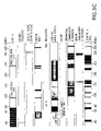
- FIGS. 5A–5D depict some frequency allocations operable with the present invention
- FIG. 6 is a block diagram of a transceiver according to an embodiment of the invention.
- FIG. 7 illustrates an exemplary use scenario used to described the operation of an embodiment of the invention.
- the invention is directed to a receiver having multi-mode and multi-band functionality and capabilities.
- the receiver is capable of selectively operating over a plurality of bands and channels.
- the receiver operates in the following modes: (1) single band/channel mode; or (2) multiple band/channel mode.
- the receiver In the single band/channel mode, the receiver is configured to receive information in a particular channel of a particular frequency band.
- the receiver may be dynamically reconfigured to listen to other channels and/or other bands.
- the receiver is configured to receive information in one or more channels in one or more frequency bands.
- the receiver could be configured to receive information from a plurality of channels of a single band, or one or more channels of a plurality of bands.
- a channel in a band that is being monitored i.e., a channel in a band that the receiver is listening to
- a channel/band combination i.e., a channel in a band that the receiver is listening to
- the receiver preferably listens to each channel/band combination for a finite period of time. After the time period of a given channel/band combination expires, the receiver listens to another channel/band combination for a limited amount of time.
- the receiver listens to the channel/band combinations in a round robin manner.
- the receiver listens to each channel/band combination for the same time duration.
- the receiver listens to the channel/band combinations in other orders. For example, a user may specify the order in which the channel/band combinations are listened to by the receiver. The user may specify that some channel/band combinations are listened to more often than others. The user may specify that some channel/band combinations are listened to for durations different than the durations associated with other channel/band combinations.
- the receiver 604 is a component of a transceiver 602 .
- the transceiver 602 also includes a transmitter 606 .
- the transceiver 602 is an FRS unit that is enabled for multi-mode and multi-band operation, where the bands of operation include bands other than that associated with FRS. It is noted that this FRS embodiment is discussed herein for illustrative purposes only. The invention is not limited to this embodiment. As will be apparent to persons skilled in the relevant art(s) based on the discussion herein, the invention is applicable to other applications of receivers and transceivers.
- Other transmitters applicable with the present invention include those described in copending U.S. patent applications “Image-Reject Down-Converter and Embodiments Thereof, Such as the Family Radio Service,” Ser. No. 09/476,091, “Analog Zero IF FM Decoder and Embodiments Thereof, Such as the Family Radio Service,” Ser. No. 09/476,092, and “Multi-Mode, Multi-Band Communication System,” Ser. No. 09/476,330, which are incorporated by reference in their entireties.
- the receiver is operable at a plurality of frequency bands.
- the receiver is operable at at least all U.S. frequency allocations from 10 KHz to 4 GHz, as illustrated in FIGS. 5A–5C .
- FIG. 5D illustrates the orientation of FIGS. 5A–5C .
- FIG. 5A partially overlaps with FIG. 5B , which partially overlaps with FIG. 5C .
- this embodiment is described for illustrative purposes. The invention is not limited to these bands. As will be appreciated by persons skilled in the relevant art(s) based on the discussion herein, embodiments of the invention are applicable at other frequency ranges.
- FIG. 1 is a block diagram of a receiver 102 according to an embodiment of the invention.
- the receiver 102 includes one or more input filters and/or Z match modules 106 , an input selector 116 , a universal frequency translator 118 , an output selector 120 , one or more output filters 122 , one or more decoders 132 , a control signal generator 142 , and a controller 144 .
- the input filters and/or Z match (impedance match) modules 106 include filter and/or Z match modules 108 , 110 , 112 , 114 (four such modules are shown in FIG. 1 , but the invention is not limited to this embodiment).
- Each input filter and/or Z match module 108 , 110 , 112 , 114 operates to select or pass a frequency band.
- each input filter and/or Z match module 108 , 110 , 112 , 114 operates as a band select filter.
- each input filter and/or Z match module 108 , 110 , 112 , 114 is configured to pass a frequency band of interest.
- each input filter and/or Z match module 108 , 110 , 112 , 114 also operates to impedance match the input to downstream circuitry.
- filters and Z match modules operable for use with the present invention will be apparent to persons skilled in the relevant art(s) based on the discussion herein. Filters and Z match modules are also described in U.S. non-provisional applications “Method and System for Down-Converting Electromagnetic Signals,” Ser. No. 09/176,022, filed Oct. 21, 1998, “Integrated Frequency Translation and Selectivity,” Ser. No. 09/175,966, filed Oct. 21, 1998, “Image-Reject Down-Converter and Embodiments Thereof, Such as the Family Radio Service,” Ser. No.
- the receiver 102 includes a single filter and/or Z match module that is adjustable over a plurality of frequency bands. In another embodiment, the receiver 102 includes a plurality of filters and/or Z match modules that are adjustable over a plurality of frequency bands.
- the input selector 116 operates to select one of a plurality of input signals.
- the selected input signal is passed to an output.
- the input selector 116 includes a switch 117 .
- the switch 117 includes a plurality of input nodes and an output node.
- the switch 117 connects one of the input nodes to the output node.
- the universal frequency translator (UFT) 118 down-converts an input signal 119 .
- the UFT 118 may down-convert the input signal 119 to an IF signal, or to a demodulated baseband signal.
- the rate of a control signal 150 determines whether the input signal 119 is down-converted to an IF signal, or down-converted to a demodulated baseband signal.
- Other down-conversion options are also possible using the UFT 118 .
- the UFT 118 is further described in U.S. non-provisional application “Method and System for Down-Converting Electromagnetic Signals,” Ser. No. 09/176,022, filed Oct. 21, 1998, “Image-Reject Down-Converter and Embodiments Thereof, Such as the Family Radio Service,” Ser. No. 09/476,091, “Analog Zero IF FM Decoder and Embodiments Thereof, Such as the Family Radio Service,” Ser. No. 09/476,092, and “Multi-Mode, Multi-Band Communication System,” Ser. No. 09/476,330, which are incorporated herein by reference in their entireties.
- the control signal generator 142 generates a control signal 150 .
- the frequency of the control signal 150 is adjustable.
- the control signal generator 142 includes a voltage controlled oscillator (VCO). VCO and other types of devices operable for performing the functionality of the control signal generator 142 will be apparent to persons skilled in the relevant art(s) based on the discussion herein.
- the control signal generator 142 may include circuitry to modify characteristics of the control signal 150 , such as adjusting the pulse widths of the control signal 150 . Such aspects are described in U.S. non-provisional application “Method and System for Down-Converting Electromagnetic Signals,” Ser. No. 09/176,022, filed Oct. 21, 1998, incorporated herein by reference in its entirety.
- the output selector 120 operates to route an input signal to one of a plurality of output nodes.
- the output selector 120 includes a switch 123 .
- the switch 123 includes an input node and a plurality of output nodes.
- the switch 123 connects one of the output nodes to the input node.
- the output filters 122 include filters 124 , 126 , 128 , 130 (four such modules are shown in FIG. 1 , but the invention is not limited to this embodiment).
- Each filter 124 , 126 , 128 , 130 operates to select or pass a frequency channel. Accordingly, each filter 124 , 126 , 128 , 130 operates as a channel select filter.
- each filter 124 , 126 , 128 , 130 is configured to pass a frequency channel of interest.
- filters operable for use with the present invention will be apparent to persons skilled in the relevant art(s) based on the discussion herein. Filters are also described in U.S. non-provisional application “Integrated Frequency Translation and Selectivity,” Ser. No. 09/175,966, filed Oct. 21, 1998, incorporated herein by reference in its entirety.
- the receiver 102 includes a single output filter that is adjustable over a plurality of frequency bands. In another embodiment, the receiver 102 includes a plurality of output filters modules that are adjustable over a plurality of frequency bands.
- the receiver 102 includes decoders 132 .
- Decoders 132 preferably include a plurality of decoders 134 , 136 , 138 , 140 (four such devices are shown in FIG. 1 , but the invention is not limited to this example).
- Decoders 134 , 136 , 138 , 140 decode an input signal to obtain an output signal 148 .
- the decoders 134 , 136 , 138 , 140 are preferably configured to operate with signals of interest. A variety of decoders operable for use with the present invention will be apparent to persons skilled in the relevant art(s) based on the discussion herein.
- a controller 144 issues commands to the components of the receiver 102 . Such commands control the operation of such components.
- the controller 144 is implemented using a microprocessor and/or a digital signal processor (DSP).
- DSP digital signal processor
- the controller 144 may receive instructions and/or data from users 146 .
- the receiver 102 receives input signals 104 over some communication medium.
- the communication medium may be any communication medium, including but not limited to a wireless medium or a wired medium, or a combination thereof.
- the input signals 104 may include information present in a plurality of channels of a plurality of frequency bands.
- the input signals 104 may include, without limitation, information present in one or more AM channels, one or more FM channels, one or more CB channels, one or more TV channels, one or more FRS channels, one or more Weatherband channels, local area networks, etc.
- the input signals 104 are received by the input filters and/or Z match modules 108 , 110 , 112 , 114 .
- Each of the input filters and/or Z match modules 108 , 110 , 112 , 114 are configured to pass a frequency band of interest.
- the input filter and/or Z match module 108 may be configured to pass the AM band.
- the input filter and/or Z match module 110 may be configured to pass a band of frequencies associated with a local area network (LAN).
- the input filter and/or Z match module 112 may be configured to pass the FRS band.
- the input filter and/or Z match module 114 may be configured to pass the Weather band.
- the input filters and/or Z match modules 108 , 110 , 112 , 114 pass those input signals 104 that fall within their respective bands.
- the filter and/or Z match modules 108 , 110 , 112 , 114 generate filtered signals. These filtered signals are received by the input selector 116 . At any instance of time, the input selector 116 routes one of these filtered signals to the universal frequency translator (UFT) 118 . Switching and routing by the input selector 116 is controlled by the controller 144 . The filtered signal that is routed to the UFT 118 corresponds to a channel/band combination that is currently being processed or monitored (this channel/band combination is referred to as the “current channel/band”).
- the UFT 118 down-converts the filtered signal that it receives from the input selector 116 to a lower frequency suitable for down-stream processing.
- the operation of the UFT 118 is controlled by the controller 144 .
- the controller 144 establishes the frequency of the control signal 150 generated by the control signal generator 142 , which controls the down-conversion operation performed by the UFT 118 .
- the output selector 120 routes the down-converted signal to an output filter 122 associated with the current channel/band. Switching and routing performed by the output selector 120 is controlled by the controller 144 . Assume, for example purposes, that the filter 126 is associated with the current channel/band. In this case, the output selector 120 routes the down-converted signal to the filter 126 .
- the filter 126 is configured to pass a channel within the band of the “current channel/band.”
- the channel filtered signal is passed to the decoder 136 coupled to the filter 126 .
- the decoder 136 decodes the channel filtered signal to obtain the output signal 148 .
- the output signal 148 is thereafter processed in an application dependent manner.
- FIG. 2 illustrates a receiver 202 according to an alternative embodiment of the invention.
- the receiver 202 includes a unified down-converting and filtering (UDF) module 206 .
- UDF down-converting and filtering
- the UDF module 206 performs frequency selectivity and frequency translation as a single unified (i.e., integrated) operation. By performing frequency selectivity and translation as a single unified operation, the invention achieves high frequency selectivity prior to frequency translation.
- the invention achieves high frequency selectivity at any input frequency (the input frequency refers to the frequency of the input spectrum being filtered and translated), including but not limited to RF (radio frequency) and greater frequencies. It should be understood that the invention is not limited to this example of RF and greater frequencies. The invention is intended, adapted, and capable of working with lower than radio frequencies.
- the effect achieved by the UDF module 206 is to perform the frequency selectivity operation prior to the performance of the frequency translation operation.
- the UDF module 206 effectively performs input filtering.
- such input filtering involves a relatively narrow bandwidth.
- such input filtering represents channel select filtering, where the filter bandwidth may be, for example and without limitation, 50 KHz to 150 KHz. It should be understood, however, that the invention is not limited to these frequencies. The invention is intended, adapted, and capable of achieving filter bandwidths of less than and greater than these values.
- the UDF module 206 of the present invention includes a number of advantages. For example, high selectivity at high frequencies is realizable using the UDF module 206 . This feature of the invention is evident by the high Q factors that are attainable.
- the invention is not limited to filters with high Q factors.
- the filters contemplated by the present invention may have lesser or greater Qs, depending on the application, design, and/or implementation. Also, the scope of the invention includes filters where Q factor as described herein is not applicable.
- the filtering center frequency f C and other filtering characteristics of the UDF module 206 can be electrically adjusted, either statically or dynamically.
- the frequency translation characteristics of the UDF module 206 can be electrically adjusted, either statically or dynamically.
- the UDF module 206 can be designed to amplify input signals 204 .
- the UDF module 206 can be implemented without large resistors, capacitors, or inductors. Also, the UDF module 206 does not require that high tolerances be maintained on its individual components, i.e., its resistors, capacitors, inductors, etc. As a result, the architecture of the UDF module 206 is friendly to integrated circuit design techniques and processes.
- the UDF module 206 operationally replaces the band select filtering, frequency translation, and channel select filtering operations performed by the input filters and/or Z match modules 106 , the UFT 118 , and the output filters 122 of the receiver 102 of FIG. 1 .
- the output of the UDF module 206 is a channel filtered and down-converted signal corresponding to the current channel/band.
- the filtering and down-conversion characteristics of the UDF module 206 are adjusted pursuant to the current channel/band (so as to appropriately process the current channel/band) based on commands issued by the controller 212 to the UDF 206 and the control signal generator 210 .
- the channel filtered and down-converted signal generated by the UDF module 206 is received by decoder(s) 216 .
- the receiver 202 may include an output selector (not shown), similar to that described with respect to FIG. 1 , to route the channel filtered and down-converted signal to one of the decoders 216 associated with the current channel/band.
- the decoders 216 may represent an adjustable decoder whose operation is controlled by the controller 212 .
- the decoder then decodes the channel filtered and down-converted signal to produce the output signal 218 .
- the output signal 218 is thereafter processed in an application dependent manner.
- the UDF module is further described in U.S. non-provisional application “Integrated Frequency Translation and Selectivity,” Ser. No. 09/175,966, filed Oct. 21, 1998, incorporated herein by reference in its entirety.
- the operation of the receiver 604 is further described below.
- the receiver 604 may represent either the receiver 102 of FIG. 1 , or the receiver 202 of FIG. 2 .
- Other embodiments of the receiver 604 will be apparent to persons skilled in the relevant art(s) based on the discussion herein.
- the receiver 604 is considered to be a component of a transceiver 602 .
- the transceiver 602 also includes a transmitter 606 .
- the transceiver 602 is an FRS unit enabled for multi-mode and multi-band operation, although the invention is not limited to this embodiment.
- a user 704 (also represented by user 146 / 214 ) has the FRS unit 602 , which is coupled to a computer 718 via a wireless or wired connection (alternatively, the computer 718 may be integrated with the FRS unit 602 ).
- the user 704 is using the FRS unit 602 to communicate with user 706 (FCC rules permitting), who may be a family member.
- User 706 includes a second FRS unit 707 , and communicates with user 704 via FRS channel 724 .
- the user 704 also wishes to communicate with user 720 (FCC rules permitting), who may be another family member.
- the user 720 includes a third FRS unit 722 , and communicates with user 704 via FRS channel 726 .
- the user 704 also wishes to receive an FM channel 730 from FM station 708 , an FM channel 732 from FM station 710 , a weather channel 734 from weather station 712 , a TV channel 736 from TV station 714 , and network communication 738 from a local area network (LAN) 716 .
- LAN local area network
- Such network communication 738 may be routed to and processed by computer 718 .
- the invention enables the user 704 to receive all of these signals (and others) using the FRS unit 602 .
- the filter and/or Z match modules 108 and 110 may be configured for the FM band.
- the filters 124 and 126 may be configured for FM channels 730 and 732 , respectively.
- decoders 134 and 136 may be configured for FM channels 730 and 732 , respectively.
- the filter and/or Z match module 112 may be configured for the weather band, and filter 128 and decoder 138 may be configured for the weather channel 734 .
- the filter and/or Z match module 114 may be configured for an appropriate TV band, and the filter 130 and decoder 140 may be configured for TV channel 736 .
- Other filter and/or Z match modules 106 , output filters 122 , and decoders 132 may be similarly configured for network communication 738 , FRS channel 726 , and FRS channel 724 .
- the user 704 can enter an appropriate command(s) into the FRS unit 602 to cause the FRS unit 602 to enable and/or adjust the components contained therein for operation with the FM channel 730 .
- the input selector 116 will switch to connect the filter and/or Z match module 108 to the UFT 118 .
- the output selector 120 will switch to connect the UFT 118 to the filter 124 .
- the control signal generator 142 will generate a control signal 150 having a frequency appropriate for down-converting the FM channel 730 .
- the user 704 may issue such commands by, for example, pressing keys on a keypad of the FRS unit 602 . Other means for issuing commands are envisioned, such as voice activation.
- the user 704 can easily switch to any of the other sources of information of interest. For example, if the user 704 wishes to receive the TV channel 736 , the user 704 can enter an appropriate command into the FRS unit 602 to cause the FRS unit 602 to enable and/or adjust the components contained therein for operation with the TV channel 736 .
- the input selector 116 will switch to connect the filter and/or Z match module 114 to the UFT 118 .
- the output selector 120 will switch to connect the UFT 118 to the filter 130 .
- the control signal generator 142 will generate a control signal 150 having a frequency appropriate for down-converting the TV channel 736 .
- the user 704 may issue such commands by, for example, pressing keys on a keypad of the FRS unit 602 . Other means for issuing commands are envisioned, such as voice activation.
- the receiver 102 has a scan mode.
- the controller 144 automatically scans among the programmed channel/band combinations. Specifically, the components within the FRS unit 602 are adjusted for operation with a channel/band combination. After some time period, which may be pre-programmed, user programmed, dynamically programmed, random, fixed, etc., the components within the FRS unit 602 are adjusted for operation with a different channel/band combination. Such scanning operation continues until receipt of some command. It is noted that the scanning mode is not limited to programmed channel/band combinations.
- the receiver 102 can be instructed to scan throughout the frequency spectrum in any order and/or increment. Such functionality is achieved, in an embodiment, by taking advantage of the dynamic adjustability of the components of the receiver 102 , as described above.
- the receiver can be instructed to recognize and act upon particular content.
- the receiver can be instructed to listen and recognize particular content while monitoring a weather band.
- Such content may be a storm warning, for example.
- the receiver can be instructed to act in predefined ways upon receipt and recognization of such content. For example, while monitoring a weather band, if a storm warning is received, then the receiver may be programmed to issue an audible alarm and/or to switch to the weather band until further user command to enable the user to receive weather updates.
- Channel/band combinations can be programmed in the receiver 102 .
- the FM channel 730 is programmed in the receiver 102 by adjusting or otherwise establishing the filter and/or Z match 108 for operation in the FM band, by adjusting or otherwise establishing the filter 124 and the decoder 134 for operation with the FM channel 730 , programming the controller 144 with information sufficient for generating a control signal 150 (using the control signal generator 142 ) having a frequency suitable for down-converting the FM channel 730 , and also programming the controller 144 with information to control the input selector 116 and the output selector 120 when operating with the FM channel 730 .
- Channel/band combinations can be pre-programmed, user programmed, downloaded from an information source such as the Internet or a computer, or via any well known programming means.
- the operation of the FRS unit 602 is further described below.
- the invention supports a variety of modes, as indicated above. Additional modes of operation will be apparent to persons skilled in the relevant art(s) based on the discussion herein.
- One of the modes supported by the invention is a single band/channel mode.
- the receiver is configured to receive information in a particular channel of a particular frequency band.
- the receiver may be dynamically reconfigured to listen to other channels and/or other bands.
- FIG. 3 illustrates a flowchart 302 that depicts in greater detail the operation of the receiver when in the single band/channel mode. It is noted that the ordering of the steps shown in FIG. 3 is not mandatory. Other orderings of the steps of FIG. 3 are possible and within the scope and spirit of the present invention. Such other orderings will be apparent to persons skilled in the relevant art(s) based on the discussion herein.
- step 304 a band is selected.
- a channel within the selected band is selected.
- the selected channel/band combination represents the channel and band that are to be monitored/received by the receiver.
- the band and channel can be selected in steps 304 and 306 using any of the procedures discussed above, such as having a user enter an appropriate command, during the scan function, due to an interrupt or time-based command, etc.
- step 308 with respect to the embodiment of FIG. 1 , the controller 144 selects the input filter and/or Z match module 106 , the output filter 122 , and the decoder 132 that are configured for operation with the selected channel/band.
- the controller 212 instructs/adjusts the UDF 206 and selects the decoder 216 for appropriate operation with the selected channel/band.
- step 310 the controller 144 / 212 causes the control signal generator 142 / 210 to generate a control signal 150 / 208 having a frequency suitable for down-converting the selected channel/band.
- Steps 304 – 310 may be repeated for another channel/band.
- the receiver also supports a multiple band/channel mode.
- the receiver in the multiple band/channel mode, is configured to receive information in one or more channels in one or more frequency bands.
- the receiver could be configured to receive information in a plurality of channels of a single band, or one or more channels of a plurality of bands.
- a channel in a band that is being monitored i.e., a channel in a band that the receiver is listening to
- a channel/band combination is herein referred to as a channel/band combination.
- the receiver preferably listens to each channel/band combination for a finite period of time. After the time period of a given channel/band combination expires, the receiver listens to another channel/band combination for a limited amount of time.
- the receiver listens to the channel/band combinations in a round robin manner.
- the receiver listens to each channel/band combination for the same time duration.
- the receiver listens to the channel/band combinations in other orders. For example, a user may specify the order in which the channel/band combinations are listened to by the receiver. The user may specify that some channel/band combinations are listened to more often than others. The user may specify that some channel/band combinations are listened to for durations different than the durations associated with other channel/band combinations.
- FIG. 4 illustrates a flowchart 402 which depicts in greater detail the operation of the receiver when operating in the multiple band/channel mode.
- step 404 one or more bands are selected.
- step 406 for each of the selected bands, one or more channels are selected.
- the selected channel/band combinations represent the channels and bands that are to be monitored/received by the receiver.
- the bands and channels can be selected in steps 404 and 406 using any of the procedures discussed above, such as having a user enter appropriate commands, during the scan function, due to an interrupt or time-based command, etc.
- the receiver is instructed to search over the entire frequency spectrum, or a specified portion of the spectrum. In this case, the channel/band combinations represent frequencies in the specified portion of the spectrum.
- step 408 one of the channel/band combinations is selected for monitoring.
- step 410 with respect to the embodiment of FIG. 1 , the controller 144 selects the input filter and/or Z match module 106 , the output filter 122 , and the decoder 132 that are configured for operation with the selected channel/band combination.
- the controller 212 instructs/adjusts the UDF 206 and selects the decoder 216 for appropriate operation with the selected channel/band combination.
- step 412 the controller 144 / 212 causes the control signal generator 142 / 210 to generate a control signal 150 / 208 having a frequency suitable for down-converting the selected channel/band combination.
- step 414 the selected channel/band combination is monitored.
- step 416 the controller 144 / 212 determines whether a time duration associated with the selected channel/band combination has expired.
- the time duration may differ for different channel/band combinations, or may be the same for all.
- the receiver continues to monitor the selected channel/band combination. This is represented by the return to step 414 . If the time duration has expired, then another channel/band combination is selected. This is represented by the return to step 408 .
Abstract
Description
| Channel No. | (MHz) | ||
| 1 | 462.5625 | ||
| 2 | 462.5875 | ||
| 3 | 462.6125 | ||
| 4 | 462.6375 | ||
| 5 | 462.6625 | ||
| 6 | 462.6875 | ||
| 7 | 462.7125 | ||
| 8 | 467.5625 | ||
| 9 | 467.5875 | ||
| 10 | 467.6125 | ||
| 11 | 467.6375 | ||
| 12 | 467.6625 | ||
| 13 | 467.6875 | ||
| 14 | 467.7125 | ||
Other selected technical specifications are:
-
- (a) Frequency modulation (although phase modulation is allowed);
- (b) Frequency tolerance of each FRS unit must be maintained within 0.00025%;
- (c) The authorized bandwidth for an FRS unit is 12.5 kHz; and
- (d) Effective radiated power (ERP) shall not, under any condition of modulation, exceed 0.500 W.
The operating rules for the FRS are found at 47 C.F.R. 95.191–95.194. For additional technical information, see 47 C.F.R. 95.601–95.669.
(Freq. of input signal 119)=n·(Freq. of control signal 150)±(Freq. of down-converted output signal 121)
For the examples contained herein, for illustrative purposes only and without limitation, only the “+” condition will be discussed. The value of n represents a harmonic or sub-harmonic of the input signal 119 (e.g., n=0.5, 1, 2, 3, . . . ).
(900·106)÷(50·103)=18,000
Claims (16)
Priority Applications (5)
| Application Number | Priority Date | Filing Date | Title |
|---|---|---|---|
| US09/476,093 US7006805B1 (en) | 1999-01-22 | 2000-01-03 | Aliasing communication system with multi-mode and multi-band functionality and embodiments thereof, such as the family radio service |
| AU29672/00A AU2967200A (en) | 1999-01-22 | 2000-01-19 | Frequency translation and embodiments thereof such as the family radio service |
| PCT/US2000/001108 WO2000044087A2 (en) | 1999-01-22 | 2000-01-19 | Down-converter using sine to square wave converter |
| US09/569,044 US6873836B1 (en) | 1999-03-03 | 2000-05-10 | Universal platform module and methods and apparatuses relating thereto enabled by universal frequency translation technology |
| US10/973,917 US7483686B2 (en) | 1999-03-03 | 2004-10-27 | Universal platform module and methods and apparatuses relating thereto enabled by universal frequency translation technology |
Applications Claiming Priority (2)
| Application Number | Priority Date | Filing Date | Title |
|---|---|---|---|
| US11684799P | 1999-01-22 | 1999-01-22 | |
| US09/476,093 US7006805B1 (en) | 1999-01-22 | 2000-01-03 | Aliasing communication system with multi-mode and multi-band functionality and embodiments thereof, such as the family radio service |
Related Parent Applications (1)
| Application Number | Title | Priority Date | Filing Date |
|---|---|---|---|
| US09/261,129 Continuation-In-Part US6370371B1 (en) | 1998-10-21 | 1999-03-03 | Applications of universal frequency translation |
Related Child Applications (2)
| Application Number | Title | Priority Date | Filing Date |
|---|---|---|---|
| US09/476,330 Continuation-In-Part US6704549B1 (en) | 1999-01-22 | 2000-01-03 | Multi-mode, multi-band communication system |
| US09/569,044 Continuation-In-Part US6873836B1 (en) | 1999-03-03 | 2000-05-10 | Universal platform module and methods and apparatuses relating thereto enabled by universal frequency translation technology |
Publications (1)
| Publication Number | Publication Date |
|---|---|
| US7006805B1 true US7006805B1 (en) | 2006-02-28 |
Family
ID=35922888
Family Applications (1)
| Application Number | Title | Priority Date | Filing Date |
|---|---|---|---|
| US09/476,093 Expired - Lifetime US7006805B1 (en) | 1999-01-22 | 2000-01-03 | Aliasing communication system with multi-mode and multi-band functionality and embodiments thereof, such as the family radio service |
Country Status (1)
| Country | Link |
|---|---|
| US (1) | US7006805B1 (en) |
Cited By (39)
| Publication number | Priority date | Publication date | Assignee | Title |
|---|---|---|---|---|
| US20030181190A1 (en) * | 1999-04-16 | 2003-09-25 | Sorrells David F. | Method and apparatus for improving dynamic range in a communication system |
| US20030227983A1 (en) * | 2002-06-07 | 2003-12-11 | Parkervision, Inc. | Active polyphase inverter filter for quadrature signal generation |
| US20040015420A1 (en) * | 2002-07-18 | 2004-01-22 | Sorrells David F. | Networking methods and systems |
| US20040266379A1 (en) * | 2003-06-26 | 2004-12-30 | Samsung Electronics Co., Ltd. | Switching filter module for dynamic multi-channel selection |
| US20050009494A1 (en) * | 1998-10-21 | 2005-01-13 | Parkervision, Inc. | Method and system for down-converting and up-converting an electromagnetic signal, and transforms for same |
| US20050085207A1 (en) * | 2000-04-14 | 2005-04-21 | Parkervision, Inc. | Apparatus, system, and method for down-converting and up-converting electromagnetic signals |
| US20050100115A1 (en) * | 1999-04-16 | 2005-05-12 | Sorrells David F. | Method, system, and apparatus for balanced frequency Up-conversion of a baseband signal |
| US20050185741A1 (en) * | 2000-11-14 | 2005-08-25 | Parkervision, Inc. | Method and apparatus for a parallel correlator and applications thereof |
| US20060160564A1 (en) * | 2005-01-20 | 2006-07-20 | Beamish Norman J | Integrated multi-band transceiver for use in mobile communication device |
| US20060164238A1 (en) * | 2005-01-26 | 2006-07-27 | Jeyhan Karaoguz | GPS enabled cell phone with common interest alerts |
| US20070049221A1 (en) * | 2005-08-29 | 2007-03-01 | Donald William Metzger | Multiple output RF signal generator |
| KR100735316B1 (en) | 2005-06-29 | 2007-07-04 | 삼성전자주식회사 | System and method for transmitting signal in a communication system |
| US20070194854A1 (en) * | 2005-12-30 | 2007-08-23 | Stmicroelectronics Sa | Transconductance filtering circuit |
| US20070224950A1 (en) * | 1999-08-23 | 2007-09-27 | Parkervision, Inc. | Method and system for frequency up-conversion |
| US20080100372A1 (en) * | 2006-10-26 | 2008-05-01 | Chia-Liang Lin | Filter of adjustable frequency response and method thereof |
| US20090290602A1 (en) * | 2005-05-04 | 2009-11-26 | Mcneely David Lowell | Apparatus and method for frequency translation |
| US7653158B2 (en) | 2001-11-09 | 2010-01-26 | Parkervision, Inc. | Gain control in a communication channel |
| US7653145B2 (en) | 1999-08-04 | 2010-01-26 | Parkervision, Inc. | Wireless local area network (WLAN) using universal frequency translation technology including multi-phase embodiments and circuit implementations |
| US20100054377A1 (en) * | 2008-08-28 | 2010-03-04 | Honeywell International Inc. | Systems and methods for spurious signal reduction in multi-mode digital navigation receivers |
| US7693502B2 (en) | 1998-10-21 | 2010-04-06 | Parkervision, Inc. | Method and system for down-converting an electromagnetic signal, transforms for same, and aperture relationships |
| US7693230B2 (en) | 1999-04-16 | 2010-04-06 | Parkervision, Inc. | Apparatus and method of differential IQ frequency up-conversion |
| US7697916B2 (en) | 1998-10-21 | 2010-04-13 | Parkervision, Inc. | Applications of universal frequency translation |
| US7724845B2 (en) | 1999-04-16 | 2010-05-25 | Parkervision, Inc. | Method and system for down-converting and electromagnetic signal, and transforms for same |
| US7865177B2 (en) | 1998-10-21 | 2011-01-04 | Parkervision, Inc. | Method and system for down-converting an electromagnetic signal, and transforms for same, and aperture relationships |
| KR101007392B1 (en) | 2009-10-09 | 2011-01-13 | 삼성탈레스 주식회사 | Apparatus for hopping fast frequency of transmiter based on wideband wireless telecommunication system |
| US20110151816A1 (en) * | 2009-12-18 | 2011-06-23 | Silicon Laboratories, Inc. | Radio Frequency (RF) Receiver with Frequency Planning and Method Therefor |
| US7991815B2 (en) | 2000-11-14 | 2011-08-02 | Parkervision, Inc. | Methods, systems, and computer program products for parallel correlation and applications thereof |
| US20110271305A1 (en) * | 2005-10-05 | 2011-11-03 | Casio Computer Co., Ltd. | Wireless television system |
| US8160196B2 (en) | 2002-07-18 | 2012-04-17 | Parkervision, Inc. | Networking methods and systems |
| US8233855B2 (en) | 1998-10-21 | 2012-07-31 | Parkervision, Inc. | Up-conversion based on gated information signal |
| US8295406B1 (en) | 1999-08-04 | 2012-10-23 | Parkervision, Inc. | Universal platform module for a plurality of communication protocols |
| US8509762B2 (en) | 2011-05-20 | 2013-08-13 | ReVerb Networks, Inc. | Methods and apparatus for underperforming cell detection and recovery in a wireless network |
| US8665835B2 (en) | 2009-10-16 | 2014-03-04 | Reverb Networks | Self-optimizing wireless network |
| US8666349B2 (en) | 2009-12-18 | 2014-03-04 | Silicon Laboratories Inc. | Radio frequency (RF) receiver with dynamic frequency planning and method therefor |
| US9008722B2 (en) | 2012-02-17 | 2015-04-14 | ReVerb Networks, Inc. | Methods and apparatus for coordination in multi-mode networks |
| US9113353B1 (en) | 2015-02-27 | 2015-08-18 | ReVerb Networks, Inc. | Methods and apparatus for improving coverage and capacity in a wireless network |
| US9258719B2 (en) | 2011-11-08 | 2016-02-09 | Viavi Solutions Inc. | Methods and apparatus for partitioning wireless network cells into time-based clusters |
| US9369886B2 (en) | 2011-09-09 | 2016-06-14 | Viavi Solutions Inc. | Methods and apparatus for implementing a self optimizing-organizing network manager |
| US10193580B2 (en) | 2017-03-22 | 2019-01-29 | Qualcomm Incorporated | Multi-band radio-frequency reception |
Citations (109)
| Publication number | Priority date | Publication date | Assignee | Title |
|---|---|---|---|---|
| US2057613A (en) | 1932-07-28 | 1936-10-13 | Gen Electric | Diversity factor receiving system |
| US2241078A (en) | 1937-11-01 | 1941-05-06 | Frederick K Vreeland | Multiplex communication |
| US2270385A (en) | 1938-10-10 | 1942-01-20 | Hartford Nat Bank & Trust Co | Multicarrier transmission system |
| US2283575A (en) | 1938-04-19 | 1942-05-19 | Rca Corp | High frequency transmission system |
| US2358152A (en) | 1941-04-25 | 1944-09-12 | Standard Telephones Cables Ltd | Phase and frequency modulation system |
| US2410350A (en) | 1943-02-06 | 1946-10-29 | Standard Telephones Cables Ltd | Method and means for communication |
| US2451430A (en) | 1946-04-23 | 1948-10-12 | Jefferson Standard Broadcastin | Carrier frequency shift signaling |
| US2462181A (en) | 1944-09-28 | 1949-02-22 | Western Electric Co | Radio transmitting system |
| US2462069A (en) | 1942-05-07 | 1949-02-22 | Int Standard Electric Corp | Radio communication system |
| US2472798A (en) | 1943-11-29 | 1949-06-14 | Rca Corp | Low-pass filter system |
| US2497859A (en) | 1947-11-19 | 1950-02-21 | Western Union Telegraph Co | Frequency diversity telegraph system |
| US2499279A (en) | 1947-04-22 | 1950-02-28 | Ericsson Telefon Ab L M | Single side band modulator |
| US2802208A (en) | 1952-06-25 | 1957-08-06 | Charles F Hobbs | Radio frequency multiplexing |
| US2985875A (en) | 1958-02-12 | 1961-05-23 | Marconi Wireless Telegraph Co | Radio communication systems |
| US3023309A (en) | 1960-12-19 | 1962-02-27 | Bell Telephone Labor Inc | Communication system |
| US3069679A (en) | 1959-04-22 | 1962-12-18 | Westinghouse Electric Corp | Multiplex communication systems |
| US3104393A (en) | 1961-10-18 | 1963-09-17 | Joseph H Vogelman | Method and apparatus for phase and amplitude control in ionospheric communications systems |
| US3114106A (en) | 1960-11-23 | 1963-12-10 | Mcmauus Robert Paul | Frequency diversity system |
| US3118117A (en) | 1959-10-30 | 1964-01-14 | Int Standard Electric Corp | Modulators for carrier communication systems |
| US3226643A (en) | 1962-01-08 | 1965-12-28 | Avco Corp | Command communication system of the rectangular wave type |
| US3246084A (en) | 1960-08-26 | 1966-04-12 | Bolt Beranek & Newman | Method of and apparatus for speech compression and the like |
| US3258694A (en) | 1964-01-03 | 1966-06-28 | Multi-channel p.m. transmitter with automatic modulation index control | |
| US3383598A (en) | 1965-02-15 | 1968-05-14 | Space General Corp | Transmitter for multiplexed phase modulated singaling system |
| US3384822A (en) | 1964-03-21 | 1968-05-21 | Nippon Electric Co | Frequency-shift-keying phase-modulation code transmission system |
| US3454718A (en) | 1966-10-03 | 1969-07-08 | Xerox Corp | Fsk transmitter with transmission of the same number of cycles of each carrier frequency |
| US3523291A (en) | 1966-09-21 | 1970-08-04 | Ibm | Data transmission system |
| US3548342A (en) | 1968-10-15 | 1970-12-15 | Ibm | Digitally controlled amplitude modulation circuit |
| US3555428A (en) | 1966-10-03 | 1971-01-12 | Xerox Corp | Fsk receiver for detecting a data signal with the same number of cycles of each carrier frequency |
| US3614630A (en) | 1969-02-04 | 1971-10-19 | Develco | Radio frequency standard and voltage controlled oscillator |
| US3614627A (en) * | 1968-10-15 | 1971-10-19 | Data Control Systems Inc | Universal demodulation system |
| US3617892A (en) | 1967-02-27 | 1971-11-02 | Rca Corp | Frequency modulation system for spreading radiated power |
| US3621402A (en) | 1970-08-03 | 1971-11-16 | Bell Telephone Labor Inc | Sampled data filter |
| US3623160A (en) | 1969-09-17 | 1971-11-23 | Sanders Associates Inc | Data modulator employing sinusoidal synthesis |
| US3626417A (en) | 1969-03-07 | 1971-12-07 | Everett A Gilbert | Hybrid frequency shift-amplitude modulated tone system |
| US3629696A (en) | 1968-08-06 | 1971-12-21 | Northeast Electronics Corp | Method and apparatus for measuring delay distortion including simultaneously applied modulated signals |
| US3662268A (en) | 1970-11-17 | 1972-05-09 | Bell Telephone Labor Inc | Diversity communication system using distinct spectral arrangements for each branch |
| US3689841A (en) | 1970-10-23 | 1972-09-05 | Signatron | Communication system for eliminating time delay effects when used in a multipath transmission medium |
| US3702440A (en) | 1970-11-16 | 1972-11-07 | Motorola Inc | Selective calling system providing an increased number of calling codes or auxiliary information transfer |
| US3714577A (en) | 1971-05-06 | 1973-01-30 | W Hayes | Single sideband am-fm modulation system |
| US3716730A (en) | 1971-04-19 | 1973-02-13 | Motorola Inc | Intermodulation rejection capabilities of field-effect transistor radio frequency amplifiers and mixers |
| US3717844A (en) | 1969-04-03 | 1973-02-20 | Inst Francais Du Petrole | Process of high reliability for communications between a master installation and secondary installations and device for carrying out this process |
| US3735048A (en) | 1971-05-28 | 1973-05-22 | Motorola Inc | In-band data transmission system |
| US3736513A (en) | 1971-06-28 | 1973-05-29 | Warwick Electronics Inc | Receiver tuning system |
| US3767984A (en) | 1969-09-03 | 1973-10-23 | Nippon Electric Co | Schottky barrier type field effect transistor |
| US3806811A (en) | 1972-01-20 | 1974-04-23 | Gte Sylvania Inc | Multiple carrier phase modulated signal generating apparatus |
| US3852530A (en) | 1973-03-19 | 1974-12-03 | M Shen | Single stage power amplifiers for multiple signal channels |
| US3868601A (en) | 1973-06-18 | 1975-02-25 | Us Navy | Digital single-sideband modulator |
| US3940697A (en) * | 1974-12-02 | 1976-02-24 | Hy-Gain Electronics Corporation | Multiple band scanning radio |
| US3949300A (en) | 1974-07-03 | 1976-04-06 | Sadler William S | Emergency radio frequency warning device |
| US3967202A (en) | 1974-07-25 | 1976-06-29 | Northern Illinois Gas Company | Data transmission system including an RF transponder for generating a broad spectrum of intelligence bearing sidebands |
| US3980945A (en) | 1974-10-07 | 1976-09-14 | Raytheon Company | Digital communications system with immunity to frequency selective fading |
| US3987280A (en) | 1975-05-21 | 1976-10-19 | The United States Of America As Represented By The Secretary Of The Navy | Digital-to-bandpass converter |
| US3991277A (en) | 1973-02-15 | 1976-11-09 | Yoshimutsu Hirata | Frequency division multiplex system using comb filters |
| US4003002A (en) | 1974-09-12 | 1977-01-11 | U.S. Philips Corporation | Modulation and filtering device |
| US4013966A (en) | 1975-10-16 | 1977-03-22 | The United States Of America As Represented By The Secretary Of The Navy | Fm rf signal generator using step recovery diode |
| US4016366A (en) * | 1974-07-17 | 1977-04-05 | Sansui Electric Co., Ltd. | Compatible stereophonic receiver |
| US4017798A (en) | 1975-09-08 | 1977-04-12 | Ncr Corporation | Spread spectrum demodulator |
| US4019140A (en) | 1975-10-24 | 1977-04-19 | Bell Telephone Laboratories, Incorporated | Methods and apparatus for reducing intelligible crosstalk in single sideband radio systems |
| US4032847A (en) | 1976-01-05 | 1977-06-28 | Raytheon Company | Distortion adapter receiver having intersymbol interference correction |
| US4035732A (en) | 1974-10-03 | 1977-07-12 | The United States Of America As Represented By The Secretary Of The Army | High dynamic range receiver front end mixer requiring low local oscillator injection power |
| US4045740A (en) * | 1975-10-28 | 1977-08-30 | The United States Of America As Represented By The Secretary Of The Army | Method for optimizing the bandwidth of a radio receiver |
| US4047121A (en) | 1975-10-16 | 1977-09-06 | The United States Of America As Represented By The Secretary Of The Navy | RF signal generator |
| US4051475A (en) | 1976-07-21 | 1977-09-27 | The United States Ofamerica As Represented By The Secretary Of The Army | Radio receiver isolation system |
| US4066841A (en) | 1974-01-25 | 1978-01-03 | Serck Industries Limited | Data transmitting systems |
| US4066919A (en) | 1976-04-01 | 1978-01-03 | Motorola, Inc. | Sample and hold circuit |
| US4080573A (en) | 1976-07-16 | 1978-03-21 | Motorola, Inc. | Balanced mixer using complementary devices |
| US4081748A (en) | 1976-07-01 | 1978-03-28 | Northern Illinois Gas Company | Frequency/space diversity data transmission system |
| US4115737A (en) * | 1975-11-13 | 1978-09-19 | Sony Corporation | Multi-band tuner |
| US4130806A (en) | 1976-05-28 | 1978-12-19 | U.S. Philips Corporation | Filter and demodulation arrangement |
| US4130765A (en) | 1977-05-31 | 1978-12-19 | Rafi Arakelian | Low supply voltage frequency multiplier with common base transistor amplifier |
| US4132952A (en) * | 1975-11-11 | 1979-01-02 | Sony Corporation | Multi-band tuner with fixed broadband input filters |
| US4142155A (en) | 1976-05-19 | 1979-02-27 | Nippon Telegraph And Telephone Public Corporation | Diversity system |
| US4170764A (en) | 1978-03-06 | 1979-10-09 | Bell Telephone Laboratories, Incorporated | Amplitude and frequency modulation system |
| US4204171A (en) | 1978-05-30 | 1980-05-20 | Rca Corporation | Filter which tracks changing frequency of input signal |
| US4210872A (en) | 1978-09-08 | 1980-07-01 | American Microsystems, Inc. | High pass switched capacitor filter section |
| US4220977A (en) | 1977-10-27 | 1980-09-02 | Sony Corporation | Signal transmission circuit |
| US4245355A (en) | 1979-08-08 | 1981-01-13 | Eaton Corporation | Microwave frequency converter |
| US4250458A (en) | 1979-05-31 | 1981-02-10 | Digital Communications Corporation | Baseband DC offset detector and control circuit for DC coupled digital demodulator |
| US4253069A (en) | 1978-03-31 | 1981-02-24 | Siemens Aktiengesellschaft | Filter circuit having a biquadratic transfer function |
| US4253066A (en) | 1980-05-13 | 1981-02-24 | Fisher Charles B | Synchronous detection with sampling |
| US4253067A (en) | 1978-12-11 | 1981-02-24 | Rockwell International Corporation | Baseband differentially phase encoded radio signal detector |
| US4308614A (en) | 1978-10-26 | 1981-12-29 | Fisher Charles B | Noise-reduction sampling system |
| US4320536A (en) | 1979-09-18 | 1982-03-16 | Dietrich James L | Subharmonic pumped mixer circuit |
| US4320361A (en) | 1979-07-20 | 1982-03-16 | Marconi Instruments Limited | Amplitude and frequency modulators using a switchable component controlled by data signals |
| US4334324A (en) | 1980-10-31 | 1982-06-08 | Rca Corporation | Complementary symmetry FET frequency converter circuits |
| US4346477A (en) * | 1977-08-01 | 1982-08-24 | E-Systems, Inc. | Phase locked sampling radio receiver |
| US4355401A (en) | 1979-09-28 | 1982-10-19 | Nippon Electric Co., Ltd. | Radio transmitter/receiver for digital and analog communications system |
| US4356558A (en) | 1979-12-20 | 1982-10-26 | Martin Marietta Corporation | Optimum second order digital filter |
| US4360867A (en) | 1980-12-08 | 1982-11-23 | Bell Telephone Laboratories, Incorporated | Broadband frequency multiplication by multitransition operation of step recovery diode |
| US4363132A (en) | 1980-01-29 | 1982-12-07 | Thomson-Csf | Diversity radio transmission system having a simple and economical structure |
| US4365217A (en) | 1979-11-30 | 1982-12-21 | Thomson-Csf | Charge-transfer switched-capacity filter |
| US4369522A (en) | 1978-07-03 | 1983-01-18 | Motorola, Inc. | Singly-balanced active mixer circuit |
| US4370572A (en) | 1980-01-17 | 1983-01-25 | Trw Inc. | Differential sample-and-hold circuit |
| US4384357A (en) | 1981-04-03 | 1983-05-17 | Canadian Patens & Development Limited | Self-synchronization circuit for a FFSK or MSK demodulator |
| US4389579A (en) | 1979-02-13 | 1983-06-21 | Motorola, Inc. | Sample and hold circuit |
| US4392255A (en) | 1980-01-11 | 1983-07-05 | Thomson-Csf | Compact subharmonic mixer for EHF wave receiver using a single wave guide and receiver utilizing such a mixer |
| US4393395A (en) | 1981-01-26 | 1983-07-12 | Rca Corporation | Balanced modulator with feedback stabilization of carrier balance |
| US4430629A (en) | 1980-04-25 | 1984-02-07 | Siemens Aktiengesellschaft | Electrical filter circuit operated with a definite sampling and clock frequency fT which consists of CTD elements |
| US4441080A (en) | 1981-12-17 | 1984-04-03 | Bell Telephone Laboratories, Incorporated | Amplifier with controlled gain |
| US4446438A (en) | 1981-10-26 | 1984-05-01 | Gte Automatic Electric Incorporated | Switched capacitor n-path filter |
| US4456990A (en) | 1982-02-10 | 1984-06-26 | Fisher Charles B | Periodic wave elimination by negative feedback |
| US4470145A (en) | 1982-07-26 | 1984-09-04 | Hughes Aircraft Company | Single sideband quadricorrelator |
| US4472785A (en) | 1980-10-13 | 1984-09-18 | Victor Company Of Japan, Ltd. | Sampling frequency converter |
| US4479226A (en) | 1982-03-29 | 1984-10-23 | At&T Bell Laboratories | Frequency-hopped single sideband mobile radio system |
| US4481642A (en) | 1981-06-02 | 1984-11-06 | Texas Instruments Incorporated | Integrated circuit FSK modem |
| US4481490A (en) | 1982-06-07 | 1984-11-06 | Ael Microtel, Ltd. | Modulator utilizing high and low frequency carriers |
| US5710992A (en) * | 1996-07-12 | 1998-01-20 | Uniden America Corporation | Chain search in a scanning receiver |
| US5790587A (en) * | 1991-05-13 | 1998-08-04 | Omnipoint Corporation | Multi-band, multi-mode spread-spectrum communication system |
| US5937013A (en) * | 1997-01-03 | 1999-08-10 | The Hong Kong University Of Science & Technology | Subharmonic quadrature sampling receiver and design |
-
2000
- 2000-01-03 US US09/476,093 patent/US7006805B1/en not_active Expired - Lifetime
Patent Citations (109)
| Publication number | Priority date | Publication date | Assignee | Title |
|---|---|---|---|---|
| US2057613A (en) | 1932-07-28 | 1936-10-13 | Gen Electric | Diversity factor receiving system |
| US2241078A (en) | 1937-11-01 | 1941-05-06 | Frederick K Vreeland | Multiplex communication |
| US2283575A (en) | 1938-04-19 | 1942-05-19 | Rca Corp | High frequency transmission system |
| US2270385A (en) | 1938-10-10 | 1942-01-20 | Hartford Nat Bank & Trust Co | Multicarrier transmission system |
| US2358152A (en) | 1941-04-25 | 1944-09-12 | Standard Telephones Cables Ltd | Phase and frequency modulation system |
| US2462069A (en) | 1942-05-07 | 1949-02-22 | Int Standard Electric Corp | Radio communication system |
| US2410350A (en) | 1943-02-06 | 1946-10-29 | Standard Telephones Cables Ltd | Method and means for communication |
| US2472798A (en) | 1943-11-29 | 1949-06-14 | Rca Corp | Low-pass filter system |
| US2462181A (en) | 1944-09-28 | 1949-02-22 | Western Electric Co | Radio transmitting system |
| US2451430A (en) | 1946-04-23 | 1948-10-12 | Jefferson Standard Broadcastin | Carrier frequency shift signaling |
| US2499279A (en) | 1947-04-22 | 1950-02-28 | Ericsson Telefon Ab L M | Single side band modulator |
| US2497859A (en) | 1947-11-19 | 1950-02-21 | Western Union Telegraph Co | Frequency diversity telegraph system |
| US2802208A (en) | 1952-06-25 | 1957-08-06 | Charles F Hobbs | Radio frequency multiplexing |
| US2985875A (en) | 1958-02-12 | 1961-05-23 | Marconi Wireless Telegraph Co | Radio communication systems |
| US3069679A (en) | 1959-04-22 | 1962-12-18 | Westinghouse Electric Corp | Multiplex communication systems |
| US3118117A (en) | 1959-10-30 | 1964-01-14 | Int Standard Electric Corp | Modulators for carrier communication systems |
| US3246084A (en) | 1960-08-26 | 1966-04-12 | Bolt Beranek & Newman | Method of and apparatus for speech compression and the like |
| US3114106A (en) | 1960-11-23 | 1963-12-10 | Mcmauus Robert Paul | Frequency diversity system |
| US3023309A (en) | 1960-12-19 | 1962-02-27 | Bell Telephone Labor Inc | Communication system |
| US3104393A (en) | 1961-10-18 | 1963-09-17 | Joseph H Vogelman | Method and apparatus for phase and amplitude control in ionospheric communications systems |
| US3226643A (en) | 1962-01-08 | 1965-12-28 | Avco Corp | Command communication system of the rectangular wave type |
| US3258694A (en) | 1964-01-03 | 1966-06-28 | Multi-channel p.m. transmitter with automatic modulation index control | |
| US3384822A (en) | 1964-03-21 | 1968-05-21 | Nippon Electric Co | Frequency-shift-keying phase-modulation code transmission system |
| US3383598A (en) | 1965-02-15 | 1968-05-14 | Space General Corp | Transmitter for multiplexed phase modulated singaling system |
| US3523291A (en) | 1966-09-21 | 1970-08-04 | Ibm | Data transmission system |
| US3555428A (en) | 1966-10-03 | 1971-01-12 | Xerox Corp | Fsk receiver for detecting a data signal with the same number of cycles of each carrier frequency |
| US3454718A (en) | 1966-10-03 | 1969-07-08 | Xerox Corp | Fsk transmitter with transmission of the same number of cycles of each carrier frequency |
| US3617892A (en) | 1967-02-27 | 1971-11-02 | Rca Corp | Frequency modulation system for spreading radiated power |
| US3629696A (en) | 1968-08-06 | 1971-12-21 | Northeast Electronics Corp | Method and apparatus for measuring delay distortion including simultaneously applied modulated signals |
| US3548342A (en) | 1968-10-15 | 1970-12-15 | Ibm | Digitally controlled amplitude modulation circuit |
| US3614627A (en) * | 1968-10-15 | 1971-10-19 | Data Control Systems Inc | Universal demodulation system |
| US3614630A (en) | 1969-02-04 | 1971-10-19 | Develco | Radio frequency standard and voltage controlled oscillator |
| US3626417A (en) | 1969-03-07 | 1971-12-07 | Everett A Gilbert | Hybrid frequency shift-amplitude modulated tone system |
| US3717844A (en) | 1969-04-03 | 1973-02-20 | Inst Francais Du Petrole | Process of high reliability for communications between a master installation and secondary installations and device for carrying out this process |
| US3767984A (en) | 1969-09-03 | 1973-10-23 | Nippon Electric Co | Schottky barrier type field effect transistor |
| US3623160A (en) | 1969-09-17 | 1971-11-23 | Sanders Associates Inc | Data modulator employing sinusoidal synthesis |
| US3621402A (en) | 1970-08-03 | 1971-11-16 | Bell Telephone Labor Inc | Sampled data filter |
| US3689841A (en) | 1970-10-23 | 1972-09-05 | Signatron | Communication system for eliminating time delay effects when used in a multipath transmission medium |
| US3702440A (en) | 1970-11-16 | 1972-11-07 | Motorola Inc | Selective calling system providing an increased number of calling codes or auxiliary information transfer |
| US3662268A (en) | 1970-11-17 | 1972-05-09 | Bell Telephone Labor Inc | Diversity communication system using distinct spectral arrangements for each branch |
| US3716730A (en) | 1971-04-19 | 1973-02-13 | Motorola Inc | Intermodulation rejection capabilities of field-effect transistor radio frequency amplifiers and mixers |
| US3714577A (en) | 1971-05-06 | 1973-01-30 | W Hayes | Single sideband am-fm modulation system |
| US3735048A (en) | 1971-05-28 | 1973-05-22 | Motorola Inc | In-band data transmission system |
| US3736513A (en) | 1971-06-28 | 1973-05-29 | Warwick Electronics Inc | Receiver tuning system |
| US3806811A (en) | 1972-01-20 | 1974-04-23 | Gte Sylvania Inc | Multiple carrier phase modulated signal generating apparatus |
| US3991277A (en) | 1973-02-15 | 1976-11-09 | Yoshimutsu Hirata | Frequency division multiplex system using comb filters |
| US3852530A (en) | 1973-03-19 | 1974-12-03 | M Shen | Single stage power amplifiers for multiple signal channels |
| US3868601A (en) | 1973-06-18 | 1975-02-25 | Us Navy | Digital single-sideband modulator |
| US4066841A (en) | 1974-01-25 | 1978-01-03 | Serck Industries Limited | Data transmitting systems |
| US3949300A (en) | 1974-07-03 | 1976-04-06 | Sadler William S | Emergency radio frequency warning device |
| US4016366A (en) * | 1974-07-17 | 1977-04-05 | Sansui Electric Co., Ltd. | Compatible stereophonic receiver |
| US3967202A (en) | 1974-07-25 | 1976-06-29 | Northern Illinois Gas Company | Data transmission system including an RF transponder for generating a broad spectrum of intelligence bearing sidebands |
| US4003002A (en) | 1974-09-12 | 1977-01-11 | U.S. Philips Corporation | Modulation and filtering device |
| US4035732A (en) | 1974-10-03 | 1977-07-12 | The United States Of America As Represented By The Secretary Of The Army | High dynamic range receiver front end mixer requiring low local oscillator injection power |
| US3980945A (en) | 1974-10-07 | 1976-09-14 | Raytheon Company | Digital communications system with immunity to frequency selective fading |
| US3940697A (en) * | 1974-12-02 | 1976-02-24 | Hy-Gain Electronics Corporation | Multiple band scanning radio |
| US3987280A (en) | 1975-05-21 | 1976-10-19 | The United States Of America As Represented By The Secretary Of The Navy | Digital-to-bandpass converter |
| US4017798A (en) | 1975-09-08 | 1977-04-12 | Ncr Corporation | Spread spectrum demodulator |
| US4047121A (en) | 1975-10-16 | 1977-09-06 | The United States Of America As Represented By The Secretary Of The Navy | RF signal generator |
| US4013966A (en) | 1975-10-16 | 1977-03-22 | The United States Of America As Represented By The Secretary Of The Navy | Fm rf signal generator using step recovery diode |
| US4019140A (en) | 1975-10-24 | 1977-04-19 | Bell Telephone Laboratories, Incorporated | Methods and apparatus for reducing intelligible crosstalk in single sideband radio systems |
| US4045740A (en) * | 1975-10-28 | 1977-08-30 | The United States Of America As Represented By The Secretary Of The Army | Method for optimizing the bandwidth of a radio receiver |
| US4132952A (en) * | 1975-11-11 | 1979-01-02 | Sony Corporation | Multi-band tuner with fixed broadband input filters |
| US4115737A (en) * | 1975-11-13 | 1978-09-19 | Sony Corporation | Multi-band tuner |
| US4032847A (en) | 1976-01-05 | 1977-06-28 | Raytheon Company | Distortion adapter receiver having intersymbol interference correction |
| US4066919A (en) | 1976-04-01 | 1978-01-03 | Motorola, Inc. | Sample and hold circuit |
| US4142155A (en) | 1976-05-19 | 1979-02-27 | Nippon Telegraph And Telephone Public Corporation | Diversity system |
| US4130806A (en) | 1976-05-28 | 1978-12-19 | U.S. Philips Corporation | Filter and demodulation arrangement |
| US4081748A (en) | 1976-07-01 | 1978-03-28 | Northern Illinois Gas Company | Frequency/space diversity data transmission system |
| US4080573A (en) | 1976-07-16 | 1978-03-21 | Motorola, Inc. | Balanced mixer using complementary devices |
| US4051475A (en) | 1976-07-21 | 1977-09-27 | The United States Ofamerica As Represented By The Secretary Of The Army | Radio receiver isolation system |
| US4130765A (en) | 1977-05-31 | 1978-12-19 | Rafi Arakelian | Low supply voltage frequency multiplier with common base transistor amplifier |
| US4346477A (en) * | 1977-08-01 | 1982-08-24 | E-Systems, Inc. | Phase locked sampling radio receiver |
| US4220977A (en) | 1977-10-27 | 1980-09-02 | Sony Corporation | Signal transmission circuit |
| US4170764A (en) | 1978-03-06 | 1979-10-09 | Bell Telephone Laboratories, Incorporated | Amplitude and frequency modulation system |
| US4253069A (en) | 1978-03-31 | 1981-02-24 | Siemens Aktiengesellschaft | Filter circuit having a biquadratic transfer function |
| US4204171A (en) | 1978-05-30 | 1980-05-20 | Rca Corporation | Filter which tracks changing frequency of input signal |
| US4369522A (en) | 1978-07-03 | 1983-01-18 | Motorola, Inc. | Singly-balanced active mixer circuit |
| US4210872A (en) | 1978-09-08 | 1980-07-01 | American Microsystems, Inc. | High pass switched capacitor filter section |
| US4308614A (en) | 1978-10-26 | 1981-12-29 | Fisher Charles B | Noise-reduction sampling system |
| US4253067A (en) | 1978-12-11 | 1981-02-24 | Rockwell International Corporation | Baseband differentially phase encoded radio signal detector |
| US4389579A (en) | 1979-02-13 | 1983-06-21 | Motorola, Inc. | Sample and hold circuit |
| US4250458A (en) | 1979-05-31 | 1981-02-10 | Digital Communications Corporation | Baseband DC offset detector and control circuit for DC coupled digital demodulator |
| US4320361A (en) | 1979-07-20 | 1982-03-16 | Marconi Instruments Limited | Amplitude and frequency modulators using a switchable component controlled by data signals |
| US4245355A (en) | 1979-08-08 | 1981-01-13 | Eaton Corporation | Microwave frequency converter |
| US4320536A (en) | 1979-09-18 | 1982-03-16 | Dietrich James L | Subharmonic pumped mixer circuit |
| US4355401A (en) | 1979-09-28 | 1982-10-19 | Nippon Electric Co., Ltd. | Radio transmitter/receiver for digital and analog communications system |
| US4365217A (en) | 1979-11-30 | 1982-12-21 | Thomson-Csf | Charge-transfer switched-capacity filter |
| US4356558A (en) | 1979-12-20 | 1982-10-26 | Martin Marietta Corporation | Optimum second order digital filter |
| US4392255A (en) | 1980-01-11 | 1983-07-05 | Thomson-Csf | Compact subharmonic mixer for EHF wave receiver using a single wave guide and receiver utilizing such a mixer |
| US4370572A (en) | 1980-01-17 | 1983-01-25 | Trw Inc. | Differential sample-and-hold circuit |
| US4363132A (en) | 1980-01-29 | 1982-12-07 | Thomson-Csf | Diversity radio transmission system having a simple and economical structure |
| US4430629A (en) | 1980-04-25 | 1984-02-07 | Siemens Aktiengesellschaft | Electrical filter circuit operated with a definite sampling and clock frequency fT which consists of CTD elements |
| US4253066A (en) | 1980-05-13 | 1981-02-24 | Fisher Charles B | Synchronous detection with sampling |
| US4472785A (en) | 1980-10-13 | 1984-09-18 | Victor Company Of Japan, Ltd. | Sampling frequency converter |
| US4334324A (en) | 1980-10-31 | 1982-06-08 | Rca Corporation | Complementary symmetry FET frequency converter circuits |
| US4360867A (en) | 1980-12-08 | 1982-11-23 | Bell Telephone Laboratories, Incorporated | Broadband frequency multiplication by multitransition operation of step recovery diode |
| US4393395A (en) | 1981-01-26 | 1983-07-12 | Rca Corporation | Balanced modulator with feedback stabilization of carrier balance |
| US4384357A (en) | 1981-04-03 | 1983-05-17 | Canadian Patens & Development Limited | Self-synchronization circuit for a FFSK or MSK demodulator |
| US4481642A (en) | 1981-06-02 | 1984-11-06 | Texas Instruments Incorporated | Integrated circuit FSK modem |
| US4446438A (en) | 1981-10-26 | 1984-05-01 | Gte Automatic Electric Incorporated | Switched capacitor n-path filter |
| US4441080A (en) | 1981-12-17 | 1984-04-03 | Bell Telephone Laboratories, Incorporated | Amplifier with controlled gain |
| US4456990A (en) | 1982-02-10 | 1984-06-26 | Fisher Charles B | Periodic wave elimination by negative feedback |
| US4479226A (en) | 1982-03-29 | 1984-10-23 | At&T Bell Laboratories | Frequency-hopped single sideband mobile radio system |
| US4481490A (en) | 1982-06-07 | 1984-11-06 | Ael Microtel, Ltd. | Modulator utilizing high and low frequency carriers |
| US4470145A (en) | 1982-07-26 | 1984-09-04 | Hughes Aircraft Company | Single sideband quadricorrelator |
| US5790587A (en) * | 1991-05-13 | 1998-08-04 | Omnipoint Corporation | Multi-band, multi-mode spread-spectrum communication system |
| US5710992A (en) * | 1996-07-12 | 1998-01-20 | Uniden America Corporation | Chain search in a scanning receiver |
| US5937013A (en) * | 1997-01-03 | 1999-08-10 | The Hong Kong University Of Science & Technology | Subharmonic quadrature sampling receiver and design |
Non-Patent Citations (99)
| Title |
|---|
| "DSO takes sampling rate to 1 Ghz," Electronic Engineering, Morgan Grampian Publishers, vol. 59, No. 723, pp. 77 and 79 (Mar. 1987). |
| "New zero IF chipset from Philips," Electronic Engineering, United News & Media, vol. 67, No. 825, p. 10 (Sep. 1995). |
| Aghvami, H. et al., "Land Mobile Satellites Using the Highly Elliptic Orbits- The UK T-SAT Mobile Payload," Fourth International Conference on Satellite Systems for Mobile Communications and Navigation, IEE, pp. 147-153 (Oct. 17-19, 1988). |
| Akers, N.P. et al., "RF Sampling Gates: a Brief Review," IEE Proceedings, IEE, vol. 133, Part A, No. 1, pp. 45-49 (Jan. 1986). |
| Al-Ahmad, H.A.M. et al., "Doppler Frequency Correction for a Non-Geostationary Communications Satellite. Techniques for CERS and T-SAT," Electronics Division Colloquium on Low Noise Oscillators and Synthesizers, IEE, pp. 4/1-4/5 (Jan. 23, 1986). |
| Ali, I. et al., "Doppler Characterization for LEO Satellites," IEEE Transactions on Communications, IEEE, vol. 46, No. 3, pp. 309-313 (Mar. 1998). |
| Allan, D.W., "Statistics of Atomic Frequency Standards," Proceedings Of The IEEE Special Issue on Frequency Stability, IEEE, pp. 221-230 (Feb. 1966). |
| Allstot, D.J. and Black Jr. W.C., "Technological Design Considerations for Monolithic MOS Switched-Capacitor Filtering Systems," Proceedings of the IEEE, IEEE, vol. 71, No. 8, pp. 967-986 (Aug. 1983). |
| Allstot, D.J. et al., "MOS Switched Capacitor Ladder Filters," IEEE Journal of Solid-State Circuits, IEEE, vol. SC-13, No. 6, pp. 806-814 (Dec. 1978). |
| Alouini, M. et al., "Channel Characterization and Modeling for Ka-Band Very Small Aperture Terminals," Proceedings Of the IEEE, IEEE, vol. 85, No. 6, pp. 981-997 (Jun. 1997). |
| Andreyev, G.A. and Ogarev, S.A., "Phase Distortions of Keyed Millimeter-Wave Signals in the Case of Propagation in a Turbulent Atmosphere," Telecommunications and Radio Engineering, Scripta Technica, vol. 43, No. 12, pp. 87-90 (Dec. 1988). |
| Antonetti, A. et al., "Optoelectronic Sampling in the Picosecond Range," Optics Communications, North-Holland Publishing Company, vol. 21, No. 2, pp. 211-214 (May 1977). |
| Austin, J. et al., "Doppler Correction of the Telecommunication Payload Oscillators in the UK T-SAT," 18<SUP>th </SUP>European Microwave Conference, Microwave Exhibitions and Publishers Ltd., pp. 851-857 (Sep. 12-15, 1988). |
| Auston, D.H., "Picosecond optoelectronic switching and gating in silicon," Applied Physics Letters, American Institute of Physics, vol. 26, No. 3, pp. 101-103 (Feb. 1, 1975). |
| Baher, H., "Transfer Functions for Switched-Capacitor and Wave Digital Filters," IEEE Transactions on Circuits and Systems, IEEE Circuits and Systems Society, vol. CAS-33, No. 11, pp. 1138-1142 (Nov. 1986). |
| Baines, R., "The DSP Bottleneck," IEEE Communications Magazine, IEEE Communications Society, pp. 46-54 (May 1995). |
| Banjo, O.P. and Vilar, E. "Measurement and Modeling of Amplitude Scintillations on Low-Elevation Earth-Space Paths and Impact on Communication Systems," IEEE Transactions on Communications, IEEE Communications Society, vol. COM-34, No. 8, pp. 774-780 (Aug. 1986). |
| Banjo, O.P. and Vilar, E., "Binary Error Probabilities on Earth-Space Links Subject to Scintillation Fading," Electronics Letters, IEE, vol. 21, No. 7, pp. 296-297 (Mar. 28, 1985). |
| Banjo, O.P. and Vilar, E., "The Dependence of Slant Path Amplitude Scintillations on Various Meteorological Parameters," Fifth International Conference on Antennas and Propagation (ICAP 87) Part 2: Propagation, IEE, pp. 277-280 (Mar. 30 - Apr. 2, 1987). |
| Banjo, O.P. et al., "Tropospheric Amplitude Spectra Due to Absorption and Scattering in Earth-Space Paths," Fourth International Conference on Antennas and Propagation (ICAP 85), IEE, pp. 77-82 (Apr. 16-19, 1985). |
| Basili, P. et al., "Case Study of Intense Scintillation Events on the OTS Path," IEEE Transactions on Antennas and Propagation, IEEE, vol. 38, No. 1, pp. 107-113 (Jan. 1990). |
| Basili, P. et al., "Observation of High C<SUP>2 </SUP>and Turbulent Path Length on OTS Space-Earth Link," Electronics Letters, IEE, vol. 24, No. 17, pp. 1114-1116 (Aug. 18, 1988). |
| Blakey, J.R. et al., "Measurement of Atmospheric Millimetre-Wave Phase Scintillations in an Absorption Region," Electronics Letters, IEE, vol. 21, No. 11, pp. 486-487 (May 23, 1985). |
| Burgueño, A. et al., "Influence of rain gauge integration time on the rain rate statistics used in microwave communications," annales des tèlècommunications, International Union of Radio Science, pp. 522-527 (Sep./Oct. 1988). |
| Burgueño, A. et al., "Long Term Statistics of Precipitation Rate Return Periods in the Context of Microwave Communications," Sixth International Conference on Antennas and Propagation (ICAP 89) Part 2: Propagation, IEE, pp. 297-301 (Apr. 4-7, 1989). |
| Burgueño, A. et al., "Long-Term Joint Statistical Analysis of Duration and Intensity of Rainfall Rate with Application to Microwave Communications," Fifth International Conference on Antennas and Propagation (ICAP 87) Part 2: Propagation, IEE, pp. 198-201 (Mar. 30 - Apr. 2, 1987). |
| Burgueño, A. et al., "Spectral Analysis of 49 Years of Rainfall Rate and Relation to Fade Dynamics," IEEE Transactions on Communications, IEEE Communications Society, vol. 38, No. 9, pp. 1359-1366 (Sep. 1990). |
| Catalan, C. and Vilar, E., "Approach for satellite slant path remote sensing," Electronics Letters, IEE, vol. 34, No. 12, pp. 1238-1240 (Jun. 11, 1998). |
| Chan, P. et al., "A Highly Linear 1-GHz CMOS Downconversion Mixer," European Solid State Circuits Conference, IEEE Communication Society, pp. 210-213 (Sep. 22-24, 1993). |
| Declaration of Alex Holtz filed in U.S. Appl. No. 09/176,022, which is directed to related subject matter. |
| Declaration of Charley D. Moses, Jr. filed in U.S. Appl. No. 09/176,022, which is directed to related subject matter. |
| Declaration of Jeffrey L. Parker and David F. Sorrells, with attachment Exhibit 1, filed in U.S. Appl. No. 09/176,022, which is directed to related subject matter. |
| Declaration of Michael J. Bultman filed in U.S. Appl. No. 09/176,022, which is directed to related subject matter. |
| Declaration of Richard C. Looke filed in U.S. Appl. No. 09/176,022, which is directed to related subject matter. |
| Declaration of Robert W. Cook filed in U.S. Appl. No. 09/176,022, which is directed to related subject matter. |
| Dewey, R.J. and Collier, C.J., "Multi-Mode Radio Receiver," Electronics Division Colloquium on Digitally Implemented Radios, IEE, pp. 3/1-3/5 (Oct. 18, 1985). |
| DIALOG File 347 (JAPIO) English Language Patent Abstract for JP 2-131629, published May 21, 1990, (1 Page). |
| DIALOG File 347 (JAPIO) English Language Patent Abstract for JP 2-276351, published Nov. 13, 1990, (1 Page). |
| DIALOG File 347 (JAPIO) English Language Patent Abstract for JP 2-39632, published Feb. 8, 1990, (1 Page). |
| DIALOG File 348 (European Patents) English Language Patent Abstract for EP 0 785 635 A1, published Dec. 26, 1996, (3 Pages). |
| DIALOG File 348 (European Patents) English Language Patent Abstract for EP 35166 A1, published Feb. 18, 1981, (2 Pages). |
| Erdi, G. and Henneuse, P.R., "A Precision FET-Less Sample-and-Hold with High Charge-to-Droop Current Ratio," IEEE Journal of Solid-State Circuits, IEEE, vol. SC-13, No. 6, pp. 864-873 (Dec. 1978). |
| Faulkner, N.D. and Vilar, E., "Subharmonic Sampling for the Measurement of Short Term Stability of Microwave Oscillators," IEEE Transactions on Instrumentation and Measurement, IEEE, vol. IM-32, No. 1, pp. 208-213 (Mar. 1983). |
| Faulkner, N.D. and Vilar, E., "Time Domain Analysis of Frequency Stability Using Non-Zero Dead-Time Counter Techniques," CPEM 84 Digest Conference on Precision Electromagnetic Measurements, IEEE, pp. 81-82 (1984). |
| Faulkner, N.D. et al., "Sub-Harmonic Sampling for the Accurate Measurement of Frequency Stability of Microwave Oscillators," CPEM 82 Digest: Conference on Precision Electromagnetic Measurements, IEEE, pp. M-10 and M-11 (1982). |
| Filip, M. and Vilar, E., "Optimum Utilization of the Channel Capacity of a Satellite Link in the Presence of Amplitude Scintillations and Rain Attenuation," IEEE Transactions on Communications, IEEE Communications Society, vol. 38, No. 11, pp. 1958-1965 (Nov. 1990). |
| Fukahori, K., "A CMOS Narrow-Band Signaling Filter with Q Reduction," IEEE Journal of Solid-State Circuits, IEEE, vol. SC-19, No. 6, pp. 926-932 (Dec. 1984). |
| Fukuchi, H. and Otsu, Y., "Available time statistics of rain attenuation on earth-space path," IEE Proceedings-H: Microwaves, Antennas and Propagation, IEE, vol. 135, Pt. H, No. 6, pp. 387-390 (Dec. 1988). |
| Gibbins, C.J. and Chadha, R., "Millimetre-wave propagation through hydrocarbon flame," IEE Proceedings, IEE vol. 134, Pt. H, No. 2 , pp. 169-173 (Apr. 1987). |
| Gilchrist, B. et al., "Sampling hikes performance of frequency synthesizers," Microwaves & RF, Hayden Publishing, vol. 23, No. 1, pp. 93-94 and 110 (Jan. 1984). |
| Gossard, E.E., "Clear weather meteorological effects on propagation at frequencies above 1 Ghz," Radio Science, American Geophysical Union, vol. 16, No. 5, pp. 589-608 (Sep. - Oct. 1981). |
| Gregorian, R. et al., "Switched-Capacitor Circuit Design," Proceedings of the IEEE, IEEE, vol. 71, No. 8, pp. 941-966 (Aug. 1983). |
| Groshong et al., "Undersampling Techniques Simplify Digital Radio," Electronic Design, Penton Publishing, pp. 67-68, 70, 73-75 and 78 (May 23, 1991). |
| Grove, W.M., "Sampling for Oscilloscopes and Other RF Systems: Dc through X-Band," IEEE Transactions on Microwave Theory and Techniques, IEEE, pp. 629-635 (Dec. 1966). |
| Haddon, J. and Vilar, E., "Scattering Induced Microwave Scintillations from Clear Air and Rain on Earth Space Paths and the Influence of Antenna Aperture," IEEE Transactions on Antennas and Propagation, IEEE, vol. AP-34, No. 5, pp. 646-657 (May 1986). |
| Haddon, J. et al., "Measurement of Microwave Scintillations on a Satellite Down-Link at X-Band," Antennas and Propagation, IEE, pp. 113-117 (1981). |
| Hafdallah, H. et al., "2-4 Ghz MESFET Sampler," Electronics Letters, IEE, vol. 24, No. 3, pp. 151-153 (Feb. 4, 1988). |
| Herben, M.H.A.J., "Amplitude and Phase Scintillations Measurements on 8-2 km Line-Of-Sight Path at 30 Ghz," Electronics Letters, IEE, vol. 18, No. 7, pp. 287-289 (Apr. 1, 1982). |
| Hewitt, A. and Vilar, E., "Selective fading on LOS Microwave Links: Classical and Spread-Spectrum Measurement Techniques," IEEE Transactions on Communications, IEEE Communications Society, vol. 36, No. 7, pp. 789-796 (Jul. 1988). |
| Hewitt, A. et al., "An 18 Ghz Wideband LOS Multipath Experiment," International Conference on Measurements for Telecommunication Transmission Systems-MTTS 85, IEE, pp. 112-116 (Nov. 27-28, 1985). |
| Hewitt, A. et al., "An Autoregressive Approach to the Identification of Multipath Ray Parameters from Field Measurements," IEEE Transactions on Communications, IEEE Communications Society, vol. 37, No. 11, pp. 1136-1143 (Nov. 1989). |
| Hospitalier, E., "Instruments for Recording and Observing Rapidly Varying Phenomena," Science Abstracts, IEE, vol. VII, pp. 22-23 (1904). |
| Howard, I.M. and Swansson, N.S., "Demodulating High Frequency Resonance Signals for Bearing Fault Detection," The Institution of Engineers Australia Vibration and Noise Conference, Institution of Engineers, Australia, pp. 115-121 (Sep. 18-20, 1990). |
| Hu, X., A Switched-Current Sample-and-Hold Amplifier for FM Demodulation, Thesis for Master of Applied Science, Dept. of Electrical and Computer Engineering, University of Toronto, UMI Dissertation Services, pp. 1-64 (1995). |
| Hung, H-L. A. et al., "Characterization of Microwave Integrated Circuits Using An Optical Phase-Locking and Sampling System," IEEE MTT-S Digest, IEEE, pp. 507-510 (1991). |
| Hurst, P.J., "Shifting the Frequency Response of Switched-Capacitor Filters by Nonuniform Sampling," IEEE Transactions on Circuits and Systems, IEEE Circuits and Systems Society, vol. 38, No. 1, pp. 12-19 (Jan. 1991). |
| Itakura, T., "Effects of the sampling pulse width on the frequency characteristics of a sample-and-hold circuit," IEE Proceedings Circuits, Devices and Systems, IEE, vol. 141, No. 4, pp. 328-336 (Aug. 1994). |
| Janssen, J.M.L. and Michels, A.J., "An Experimental 'Stroboscopic' Oscilloscope for Frequencies up to about 50 Mc/s: II. Electrical Build-Up," Philips Technical Review, Philips Research Laboratories, vol. 12, No. 3, pp. 73-82 (Sep. 1950). |
| Janssen, J.M.L., "An Experimental 'Stroboscopic' Oscilloscope for Frequencies up to about 50 Mc/s: I. Fundamentals, " Philips Technical Review, Philips Research Laboratories, vol. 12, No. 2, pp. 52-59 (Aug. 1950). |
| Jondral, V.F. et al., "Doppler Profiles for Communication Satellites," Frequenz, Herausberger, pp. 111-116 (May-Jun. 1996). |
| Kaleh, G.K., "A Frequency Diversity Spread Spectrum System for Communication in the Presence of In-band Interference," 1995 IEEE Globecom, IEEE Communications Society, pp. 66-70 (1995). |
| Karasawa, Y. et al., "A New Prediction Method for Tropospheric Scintillation on Earth-Space Paths," IEEE Transactions on Antennas and Propagation, IEEE Antennas and Propagation Society, vol. 36, No. 11, pp. 1608-1614 (Nov. 1988). |
| Kirsten, J. and Fleming, J., "Undersampling reduces data-acquisition costs for select applications," EDN, Cahners Publishing, vol. 35, No. 13, pp. 217-222, 224, 226-228 (Jun. 21, 1990). |
| Lam, W.K. et al., "Measurement of the Phase Noise Characteristics of an Unlocked Communications Channel Identifier," Proceedings Of the 1993 IEEE International Frequency Control Symposium, IEEE, pp. 283-288 (Jun. 2-4, 1993). |
| Lam, W.K. et al., "Wideband sounding of 11.6 Ghz transhorizon channel," Electronics Letters, IEE, vol. 30, No. 9, pp. 738-739 (Apr. 28, 1994). |
| Larkin, K.G., "Efficient demodulator for bandpass sampled AM signals," Electronics Letters, IEE, vol. 32, No. 2, pp. 101-102 (Jan. 18, 1996). |
| Lau, W.H. et al., "Analysis of the Time Variant Structure of Microwave Line-of-sight Multipath Phenomena," IEEE Global Telecommunications Conference & Exhibition, IEEE, pp. 1707-1711 (Nov. 28 - Dec. 1, 1988). |
| Lau, W.H. et al., "Improved Prony Algorithm to Identify Multipath Components," Electronics Letters, IEE, vol. 23, No. 20, pp. 1059-1060 (Sep. 24, 1987). |
| Lesage, P. and Audoin, C., "Effect of Dead-Time on the Estimation of the Two-Sample Variance," IEEE Transactions on Instrumentation and Measurement, IEEE Instrumentation and Measurement Society, vol. IM-28, No. 1, pp. 6-10 (Mar. 1979). |
| Liechti, C.A., "Performance of Dual-gate GaAs MESFET's as Gain-Controlled Low-Noise Amplifiers and High-Speed Modulators," IEEE Transactions on Microwave Theory and Techniques, IEEE Microwave Theory and Techniques Society, vol. MTT-23, No. 6, pp. 461-469 (Jun. 1975). |
| Linnenbrink, T.E. et al., "A One Gigasample Per Second Transient Recorder," IEEE Transactions on Nuclear Science, IEEE Nuclear and Plasma Sciences Society, vol. NS-26, No. 4, pp. 4443-4449 (Aug. 1979). |
| Liou, M.L., "A Tutorial on Computer-Aided Analysis of Switched-Capacitor Circuits," Proceedings of the IEEE, IEEE, vol. 71, No. 8, pp. 987-1005 (Aug. 1983). |
| Lo, P. et al., "Coherent Automatic Gain Control," IEE Colloquium on Phase Locked Techniques, IEE, pp. 2/1-2/6 (Mar. 26, 1980). |
| Lo, P. et al., "Computation of Rain Induced Scintillations on Satellite Down-Links at Microwave Frequencies," Third International Conference on Antennas and Propagation (ICAP 83), pp. 127-131 (Apr. 12-15, 1983). |
| Lo, P.S.L.O. et al., "Observations of Amplitude Scintillations on a Low-Elevation Earth-Space Path," Electronics Letters, IEE, vol. 20, No. 7, pp. 307-308 (Mar. 29, 1984). |
| Madani, K. and Aithison, C.S., "A 20 Ghz Microwave Sampler," IEEE Transactions on Microwave Theory and Techniques, IEEE Microwave Theory and Techniques Society, vol. 40, No. 10, pp. 1960-1963 (Oct. 1992). |
| Marsland, R.A. et al., "130 Ghz GaAs monolithic integrated circuit sampling head," Appl. Phys. Lett., American Institute of Physics, vol. 55, No. 6, pp. 592-594 (Aug. 7, 1989). |
| Martin, K. and Sedra, A.S., "Switched-Capacitor Building Blocks for Adaptive Systems," IEEE Transactions on Circuits and Systems, IEEE Circuits and Systems Society, vol. CAS-28, No. 6, pp. 576-584 (Jun. 1981). |
| Marzano, F.S. and d'Auria, G., "Model-based Prediction of Amplitude Scintillation variance due to Clear-Air Tropospheric Turbulence on Earth-Satellite Microwave Links," IEEE Transactions on Antennas and Propagation, IEEE Antennas and Propagation Society, vol. 46, No. 10, pp. 1506-1518 (Oct. 1998). |
| Matricciani, E., "Prediction of fade durations due to rain in satellite communication systems," Radio Science, American Geophysical Union, vol. 32, No. 3, pp. 935-941 (May-Jun. 1997). |
| McQueen, J.G., "The Monitoring of High-Speed Waveforms," Electronic Engineering, Morgan Brothers Limited, vol. XXIV, No. 296, pp. 436-441 (Oct. 1952). |
| Merkelo, J. and Hall, R.D., "Broad-Band Thin-Film Signal Sampler," IEEE Journal of Solid-State Circuits, IEEE, vol. SC-7, No. 1, pp. 50-54 (Feb. 1972). |
| Merlo, U. et al., "Amplitude Scintillation Cycles in a Sirio Satellite-Earth Link," Electronics Letters, IEE, vol. 21, No. 23, pp. 1094-1096 (Nov. 7, 1985). |
| Morris, D., "Radio-holographic reflector measurement of the 30-m millimeter radio telescope at 22 Ghz with a cosmic signal source," Astronomy and Astrophysics, Springer-Verlag, vol. 203, No. 2, pp. 399-406 (Sep. (II) 1988). |
| Moulsley, T.J. et al., "The efficient acquisition and processing of propagation statistics," Journal of the Institution of Electronic and Radio Engineers, IERE, vol. 55, No. 3, pp. 97-103 (Mar. 1985). |
| Ndzi, D. et al., "Wide-Band Statistical Characterization of an Over-the-Sea Experimental Transhorizon Link," IEE Colloquium on Radio Communications at Microwave and Millimetre Wave Frequencies, IEE, pp. 1/1-1/6 (Dec. 16, 1996). |
| Ndzi, D. et al., "Wideband Statistics of Signal Levels and Doppler Spread on an Over-The-Sea Transhorizon Link," IEE Colloquium on Propagation Characteristics and Related System Techniques for Beyond Line-of-Sight Radio, IEE, pp. 9/1-9/6 (Nov. 24, 1997). |
| Ohara, H. et al., "First monolithic PCM filter cuts cost of telecomm systems," Electronic Design, Hayden Publishing Company, vol. 27, No. 8, pp. 130-135 (Apr. 12, 1979). |
| Oppenheim, A.V. et al., Signals and Systems, Prentice-Hall, pp. 527-531 and 561-562 (1983). |
Cited By (73)
| Publication number | Priority date | Publication date | Assignee | Title |
|---|---|---|---|---|
| US8190116B2 (en) | 1998-10-21 | 2012-05-29 | Parker Vision, Inc. | Methods and systems for down-converting a signal using a complementary transistor structure |
| US7697916B2 (en) | 1998-10-21 | 2010-04-13 | Parkervision, Inc. | Applications of universal frequency translation |
| US8160534B2 (en) | 1998-10-21 | 2012-04-17 | Parkervision, Inc. | Applications of universal frequency translation |
| US8340618B2 (en) | 1998-10-21 | 2012-12-25 | Parkervision, Inc. | Method and system for down-converting an electromagnetic signal, and transforms for same, and aperture relationships |
| US7693502B2 (en) | 1998-10-21 | 2010-04-06 | Parkervision, Inc. | Method and system for down-converting an electromagnetic signal, transforms for same, and aperture relationships |
| US20050009494A1 (en) * | 1998-10-21 | 2005-01-13 | Parkervision, Inc. | Method and system for down-converting and up-converting an electromagnetic signal, and transforms for same |
| US8233855B2 (en) | 1998-10-21 | 2012-07-31 | Parkervision, Inc. | Up-conversion based on gated information signal |
| US7826817B2 (en) | 1998-10-21 | 2010-11-02 | Parker Vision, Inc. | Applications of universal frequency translation |
| US7936022B2 (en) | 1998-10-21 | 2011-05-03 | Parkervision, Inc. | Method and circuit for down-converting a signal |
| US7937059B2 (en) | 1998-10-21 | 2011-05-03 | Parkervision, Inc. | Converting an electromagnetic signal via sub-sampling |
| US8019291B2 (en) | 1998-10-21 | 2011-09-13 | Parkervision, Inc. | Method and system for frequency down-conversion and frequency up-conversion |
| US8190108B2 (en) | 1998-10-21 | 2012-05-29 | Parkervision, Inc. | Method and system for frequency up-conversion |
| US7865177B2 (en) | 1998-10-21 | 2011-01-04 | Parkervision, Inc. | Method and system for down-converting an electromagnetic signal, and transforms for same, and aperture relationships |
| US20050100115A1 (en) * | 1999-04-16 | 2005-05-12 | Sorrells David F. | Method, system, and apparatus for balanced frequency Up-conversion of a baseband signal |
| US7894789B2 (en) | 1999-04-16 | 2011-02-22 | Parkervision, Inc. | Down-conversion of an electromagnetic signal with feedback control |
| US8036304B2 (en) | 1999-04-16 | 2011-10-11 | Parkervision, Inc. | Apparatus and method of differential IQ frequency up-conversion |
| US8223898B2 (en) | 1999-04-16 | 2012-07-17 | Parkervision, Inc. | Method and system for down-converting an electromagnetic signal, and transforms for same |
| US8224281B2 (en) | 1999-04-16 | 2012-07-17 | Parkervision, Inc. | Down-conversion of an electromagnetic signal with feedback control |
| US8229023B2 (en) | 1999-04-16 | 2012-07-24 | Parkervision, Inc. | Wireless local area network (WLAN) using universal frequency translation technology including multi-phase embodiments |
| US7929638B2 (en) | 1999-04-16 | 2011-04-19 | Parkervision, Inc. | Wireless local area network (WLAN) using universal frequency translation technology including multi-phase embodiments |
| US8594228B2 (en) | 1999-04-16 | 2013-11-26 | Parkervision, Inc. | Apparatus and method of differential IQ frequency up-conversion |
| US8077797B2 (en) | 1999-04-16 | 2011-12-13 | Parkervision, Inc. | Method, system, and apparatus for balanced frequency up-conversion of a baseband signal |
| US20030181186A1 (en) * | 1999-04-16 | 2003-09-25 | Sorrells David F. | Reducing DC offsets using spectral spreading |
| US7773688B2 (en) | 1999-04-16 | 2010-08-10 | Parkervision, Inc. | Method, system, and apparatus for balanced frequency up-conversion, including circuitry to directly couple the outputs of multiple transistors |
| US20030181190A1 (en) * | 1999-04-16 | 2003-09-25 | Sorrells David F. | Method and apparatus for improving dynamic range in a communication system |
| US7693230B2 (en) | 1999-04-16 | 2010-04-06 | Parkervision, Inc. | Apparatus and method of differential IQ frequency up-conversion |
| US7724845B2 (en) | 1999-04-16 | 2010-05-25 | Parkervision, Inc. | Method and system for down-converting and electromagnetic signal, and transforms for same |
| US8295406B1 (en) | 1999-08-04 | 2012-10-23 | Parkervision, Inc. | Universal platform module for a plurality of communication protocols |
| US7653145B2 (en) | 1999-08-04 | 2010-01-26 | Parkervision, Inc. | Wireless local area network (WLAN) using universal frequency translation technology including multi-phase embodiments and circuit implementations |
| US20070224950A1 (en) * | 1999-08-23 | 2007-09-27 | Parkervision, Inc. | Method and system for frequency up-conversion |
| US20060019617A1 (en) * | 2000-04-14 | 2006-01-26 | Parkervision, Inc. | Apparatus, system, and method for down converting and up converting electromagnetic signals |
| US7822401B2 (en) | 2000-04-14 | 2010-10-26 | Parkervision, Inc. | Apparatus and method for down-converting electromagnetic signals by controlled charging and discharging of a capacitor |
| US20050085207A1 (en) * | 2000-04-14 | 2005-04-21 | Parkervision, Inc. | Apparatus, system, and method for down-converting and up-converting electromagnetic signals |
| US8295800B2 (en) | 2000-04-14 | 2012-10-23 | Parkervision, Inc. | Apparatus and method for down-converting electromagnetic signals by controlled charging and discharging of a capacitor |
| US7991815B2 (en) | 2000-11-14 | 2011-08-02 | Parkervision, Inc. | Methods, systems, and computer program products for parallel correlation and applications thereof |
| US20050185741A1 (en) * | 2000-11-14 | 2005-08-25 | Parkervision, Inc. | Method and apparatus for a parallel correlator and applications thereof |
| US8446994B2 (en) | 2001-11-09 | 2013-05-21 | Parkervision, Inc. | Gain control in a communication channel |
| US7653158B2 (en) | 2001-11-09 | 2010-01-26 | Parkervision, Inc. | Gain control in a communication channel |
| US20030227983A1 (en) * | 2002-06-07 | 2003-12-11 | Parkervision, Inc. | Active polyphase inverter filter for quadrature signal generation |
| US20040015420A1 (en) * | 2002-07-18 | 2004-01-22 | Sorrells David F. | Networking methods and systems |
| US8407061B2 (en) | 2002-07-18 | 2013-03-26 | Parkervision, Inc. | Networking methods and systems |
| US8160196B2 (en) | 2002-07-18 | 2012-04-17 | Parkervision, Inc. | Networking methods and systems |
| US20040266379A1 (en) * | 2003-06-26 | 2004-12-30 | Samsung Electronics Co., Ltd. | Switching filter module for dynamic multi-channel selection |
| US7158768B2 (en) * | 2003-06-26 | 2007-01-02 | Samsung Electronics Co., Ltd. | Switching filter module for dynamic multi-channel selection |
| US7502625B2 (en) * | 2005-01-20 | 2009-03-10 | Skyworks Solutions, Inc. | Integrated multi-band transceiver for use in mobile communication device |
| US20060160564A1 (en) * | 2005-01-20 | 2006-07-20 | Beamish Norman J | Integrated multi-band transceiver for use in mobile communication device |
| US20060164238A1 (en) * | 2005-01-26 | 2006-07-27 | Jeyhan Karaoguz | GPS enabled cell phone with common interest alerts |
| US7899087B2 (en) * | 2005-05-04 | 2011-03-01 | Thomson Licensing | Apparatus and method for frequency translation |
| US20090290602A1 (en) * | 2005-05-04 | 2009-11-26 | Mcneely David Lowell | Apparatus and method for frequency translation |
| KR100735316B1 (en) | 2005-06-29 | 2007-07-04 | 삼성전자주식회사 | System and method for transmitting signal in a communication system |
| US7747231B2 (en) | 2005-06-29 | 2010-06-29 | Samsung Electronics Co., Ltd. | System and method for transmitting signal in a communication system |
| US20070049221A1 (en) * | 2005-08-29 | 2007-03-01 | Donald William Metzger | Multiple output RF signal generator |
| US8739226B2 (en) * | 2005-10-05 | 2014-05-27 | Casio Computer Co., Ltd. | Wireless television system |
| US20110271305A1 (en) * | 2005-10-05 | 2011-11-03 | Casio Computer Co., Ltd. | Wireless television system |
| US7511570B2 (en) * | 2005-12-30 | 2009-03-31 | Stmicroelectronics Sa | Transconductance filtering circuit |
| US20070194854A1 (en) * | 2005-12-30 | 2007-08-23 | Stmicroelectronics Sa | Transconductance filtering circuit |
| US20080100372A1 (en) * | 2006-10-26 | 2008-05-01 | Chia-Liang Lin | Filter of adjustable frequency response and method thereof |
| US9083299B2 (en) * | 2006-10-26 | 2015-07-14 | Realtek Semiconductor Corp. | Filter of adjustable frequency response and method thereof |
| US20100054377A1 (en) * | 2008-08-28 | 2010-03-04 | Honeywell International Inc. | Systems and methods for spurious signal reduction in multi-mode digital navigation receivers |
| KR101007392B1 (en) | 2009-10-09 | 2011-01-13 | 삼성탈레스 주식회사 | Apparatus for hopping fast frequency of transmiter based on wideband wireless telecommunication system |
| US9826420B2 (en) | 2009-10-16 | 2017-11-21 | Viavi Solutions Inc. | Self-optimizing wireless network |
| US8665835B2 (en) | 2009-10-16 | 2014-03-04 | Reverb Networks | Self-optimizing wireless network |
| US9226178B2 (en) | 2009-10-16 | 2015-12-29 | Reverb Networks | Self-optimizing wireless network |
| US20110151816A1 (en) * | 2009-12-18 | 2011-06-23 | Silicon Laboratories, Inc. | Radio Frequency (RF) Receiver with Frequency Planning and Method Therefor |
| US8874060B2 (en) | 2009-12-18 | 2014-10-28 | Silicon Laboratories Inc. | Radio frequency (RF) receiver with frequency planning and method therefor |
| US8666349B2 (en) | 2009-12-18 | 2014-03-04 | Silicon Laboratories Inc. | Radio frequency (RF) receiver with dynamic frequency planning and method therefor |
| US8509762B2 (en) | 2011-05-20 | 2013-08-13 | ReVerb Networks, Inc. | Methods and apparatus for underperforming cell detection and recovery in a wireless network |
| US9369886B2 (en) | 2011-09-09 | 2016-06-14 | Viavi Solutions Inc. | Methods and apparatus for implementing a self optimizing-organizing network manager |
| US9258719B2 (en) | 2011-11-08 | 2016-02-09 | Viavi Solutions Inc. | Methods and apparatus for partitioning wireless network cells into time-based clusters |
| US10003981B2 (en) | 2011-11-08 | 2018-06-19 | Viavi Solutions Inc. | Methods and apparatus for partitioning wireless network cells into time-based clusters |
| US9008722B2 (en) | 2012-02-17 | 2015-04-14 | ReVerb Networks, Inc. | Methods and apparatus for coordination in multi-mode networks |
| US9113353B1 (en) | 2015-02-27 | 2015-08-18 | ReVerb Networks, Inc. | Methods and apparatus for improving coverage and capacity in a wireless network |
| US10193580B2 (en) | 2017-03-22 | 2019-01-29 | Qualcomm Incorporated | Multi-band radio-frequency reception |
Similar Documents
| Publication | Publication Date | Title |
|---|---|---|
| US7006805B1 (en) | Aliasing communication system with multi-mode and multi-band functionality and embodiments thereof, such as the family radio service | |
| CN1123134C (en) | Multiple mode direct conversion receiver | |
| AU692642B2 (en) | Wide band radio-frequency converter having multiple use of intermediate frequency translators | |
| EP1994644B1 (en) | Rf-to-baseband receiver architecture | |
| JPH09275358A (en) | Plural-band mobile radio equipment | |
| JPH0678227A (en) | Method and apparatus for reception of broadcasting signal | |
| US5878087A (en) | Signal communication device operable in a CDMA mode and an FM mode | |
| JPH09135223A (en) | Channeled plural carrier signal processor | |
| GB2320858A (en) | Digital/Analog and PCS mode portable telephone | |
| NL8901460A (en) | RECEIVER FOR TERRESTRIAL AM AND SATELLITE FM TV BROADCASTS. | |
| JPH11298361A (en) | Radio receiver and signal amplifying method in radio receiver | |
| RU2304346C2 (en) | Using fixed-passband filters for programmable intermediate-frequency passband | |
| JP2003209479A (en) | Front end for radio frequency tuner, and tuner | |
| US6480709B2 (en) | Method for reducing scan time in a radio receiver | |
| EP1489753B1 (en) | High frequency signal receiver | |
| JPH07231273A (en) | Tuner for receiving satellite broadcast | |
| US6259902B1 (en) | Dual channel superheterodyne receiver | |
| JPH0535951B2 (en) | ||
| JP2004040814A (en) | Tuner | |
| EP1851862B1 (en) | Receiver for simultaneously receiving different standards | |
| US20050169416A1 (en) | Transceiver with multi-state direct digital synthesizer driven phase locked loop | |
| EP1207627A1 (en) | An efficient GS;/DSC/UMTS (UTRA/FDD) RF transceiver architecture | |
| JPH05244033A (en) | Dual-band radio communication device | |
| JPH11341373A (en) | Tuner for receiving digital broadcasting | |
| KR100664951B1 (en) | Apparatus and method for providing wireless lan and tuner in common |
Legal Events
| Date | Code | Title | Description |
|---|---|---|---|
| AS | Assignment |
Owner name: PARKERVISION, INC., FLORIDA Free format text: ASSIGNMENT OF ASSIGNORS INTEREST;ASSIGNORS:SORRELLS, DAVID F.;BULTMAN, MICHAEL J.;CLEMENTS, CHARLES D.;AND OTHERS;REEL/FRAME:010740/0031;SIGNING DATES FROM 20000330 TO 20000410 |
|
| STCF | Information on status: patent grant |
Free format text: PATENTED CASE |
|
| FPAY | Fee payment |
Year of fee payment: 4 |
|
| REMI | Maintenance fee reminder mailed | ||
| FPAY | Fee payment |
Year of fee payment: 8 |
|
| SULP | Surcharge for late payment |
Year of fee payment: 7 |
|
| MAFP | Maintenance fee payment |
Free format text: PAYMENT OF MAINTENANCE FEE, 12TH YEAR, LARGE ENTITY (ORIGINAL EVENT CODE: M1553) Year of fee payment: 12 |