US7008564B2 - Cured composite materials for reactive metal battery electrolytes - Google Patents
Cured composite materials for reactive metal battery electrolytes Download PDFInfo
- Publication number
- US7008564B2 US7008564B2 US10/194,376 US19437602A US7008564B2 US 7008564 B2 US7008564 B2 US 7008564B2 US 19437602 A US19437602 A US 19437602A US 7008564 B2 US7008564 B2 US 7008564B2
- Authority
- US
- United States
- Prior art keywords
- molecular composite
- composite electrolyte
- electrolyte material
- thickness
- polymer
- Prior art date
- Legal status (The legal status is an assumption and is not a legal conclusion. Google has not performed a legal analysis and makes no representation as to the accuracy of the status listed.)
- Expired - Fee Related, expires
Links
Images


Classifications
-
- H—ELECTRICITY
- H01—ELECTRIC ELEMENTS
- H01M—PROCESSES OR MEANS, e.g. BATTERIES, FOR THE DIRECT CONVERSION OF CHEMICAL ENERGY INTO ELECTRICAL ENERGY
- H01M10/00—Secondary cells; Manufacture thereof
- H01M10/05—Accumulators with non-aqueous electrolyte
- H01M10/056—Accumulators with non-aqueous electrolyte characterised by the materials used as electrolytes, e.g. mixed inorganic/organic electrolytes
-
- H—ELECTRICITY
- H01—ELECTRIC ELEMENTS
- H01M—PROCESSES OR MEANS, e.g. BATTERIES, FOR THE DIRECT CONVERSION OF CHEMICAL ENERGY INTO ELECTRICAL ENERGY
- H01M10/00—Secondary cells; Manufacture thereof
- H01M10/05—Accumulators with non-aqueous electrolyte
-
- H—ELECTRICITY
- H01—ELECTRIC ELEMENTS
- H01M—PROCESSES OR MEANS, e.g. BATTERIES, FOR THE DIRECT CONVERSION OF CHEMICAL ENERGY INTO ELECTRICAL ENERGY
- H01M4/00—Electrodes
- H01M4/02—Electrodes composed of, or comprising, active material
- H01M4/62—Selection of inactive substances as ingredients for active masses, e.g. binders, fillers
- H01M4/621—Binders
-
- H—ELECTRICITY
- H01—ELECTRIC ELEMENTS
- H01M—PROCESSES OR MEANS, e.g. BATTERIES, FOR THE DIRECT CONVERSION OF CHEMICAL ENERGY INTO ELECTRICAL ENERGY
- H01M6/00—Primary cells; Manufacture thereof
- H01M6/04—Cells with aqueous electrolyte
-
- H—ELECTRICITY
- H01—ELECTRIC ELEMENTS
- H01M—PROCESSES OR MEANS, e.g. BATTERIES, FOR THE DIRECT CONVERSION OF CHEMICAL ENERGY INTO ELECTRICAL ENERGY
- H01M6/00—Primary cells; Manufacture thereof
- H01M6/30—Deferred-action cells
- H01M6/32—Deferred-action cells activated through external addition of electrolyte or of electrolyte components
- H01M6/34—Immersion cells, e.g. sea-water cells
-
- H—ELECTRICITY
- H01—ELECTRIC ELEMENTS
- H01M—PROCESSES OR MEANS, e.g. BATTERIES, FOR THE DIRECT CONVERSION OF CHEMICAL ENERGY INTO ELECTRICAL ENERGY
- H01M10/00—Secondary cells; Manufacture thereof
- H01M10/05—Accumulators with non-aqueous electrolyte
- H01M10/052—Li-accumulators
-
- H—ELECTRICITY
- H01—ELECTRIC ELEMENTS
- H01M—PROCESSES OR MEANS, e.g. BATTERIES, FOR THE DIRECT CONVERSION OF CHEMICAL ENERGY INTO ELECTRICAL ENERGY
- H01M2300/00—Electrolytes
- H01M2300/0088—Composites
- H01M2300/0091—Composites in the form of mixtures
-
- Y—GENERAL TAGGING OF NEW TECHNOLOGICAL DEVELOPMENTS; GENERAL TAGGING OF CROSS-SECTIONAL TECHNOLOGIES SPANNING OVER SEVERAL SECTIONS OF THE IPC; TECHNICAL SUBJECTS COVERED BY FORMER USPC CROSS-REFERENCE ART COLLECTIONS [XRACs] AND DIGESTS
- Y02—TECHNOLOGIES OR APPLICATIONS FOR MITIGATION OR ADAPTATION AGAINST CLIMATE CHANGE
- Y02E—REDUCTION OF GREENHOUSE GAS [GHG] EMISSIONS, RELATED TO ENERGY GENERATION, TRANSMISSION OR DISTRIBUTION
- Y02E60/00—Enabling technologies; Technologies with a potential or indirect contribution to GHG emissions mitigation
- Y02E60/10—Energy storage using batteries
Definitions
- This invention relates generally to methods of dimensionally-stabilizing fluid-like elastomeric polymers. More specifically, the invented methods relate to stabilizing composite polymer-ceramic materials for use as solid-state battery electrolytes/separator components, wherein the resulting composite material possesses the high conductivity of a polymer electrolyte and the enhanced durability of a ceramic material.
- This invention relates to a new molecular composite material for use in all-solid-construction reactive metal batteries. The invented materials are primarily designed for use in either reserve or primary reactive metal/water batteries.
- a battery typically comprises one or more electrochemical cells connected in series, parallel, or both, depending on desired output voltage and capacity.
- Each cell principally comprises an anode, a cathode, and an electrolyte.
- the electrolyte serves as the ionic conductor and provides the medium for the transfer of ions inside the cell between the anode and the cathode, and typically comprises liquid, solid, or gel materials.
- Some batteries commonly called “primary batteries,” are intended for a single use, and, once discharged, are discarded.
- Other batteries commonly called “secondary or rechargeable” batteries, are designed to be recharged, after discharge, essentially to their original condition.
- ions from the anode pass through the liquid electrolyte to the electrochemically-active material of the cathode where the ions are taken up with the simultaneous release of electrical energy.
- the flow of ions is reversed, so that ions pass from the electrochemically-active cathode material through the electrolyte and are plated back onto the anode.
- Solid polymer electrolytes are useful in numerous applications, such as solid-state batteries, supercapacitors, fuel cells, sensors, electrochromic devices and the like.
- Solid polymer electrolytes have been proposed in the past for use in such equipment, in place of liquid electrolytes, because they combine in one material the function of electrolyte, separator, and binder for the electrode materials, thereby reducing the complexity of the ultimate structure.
- SPE solid polymer electrolyte
- SPE solid polymer electrolyte
- SPEs can be fabricated as thin films, which permit space-efficient batteries to be designed.
- flexible solid polymer electrolytes can be fabricated, which allow for volume changes in the electrochemical cell without physical degradation of the interfacial contacts.
- SPEs have been suggested for use in the prior art such as thin films formed by complexation between lithium salt and linear polyethers. See, for example, Narang, et al., U.S. Pat. No. 5,061,581.
- Li salt complexes of polymers such as poly[bis(methoxyethoxyethoxy)phosphazene] (MEEP) and poly(ethoxyethoxy-ethoxy-vinyl ether) (described by Guglielmi et al., Appl. Organometal. Chem. 13, 339–351 (1999)), prepared on the basis of these principles, have shown room temperature conductivities of around 10 ⁇ 5 S/cm. While the ionic conductivities of such polymers at ambient temperatures have fallen within acceptable limits for battery applications, they suffer from physical drawbacks, making them inappropriate for use as electrolytes. MEEP, for example, suffers from very low dimensional stability that prevents its extensive use in battery construction technology. Specifically, MEEP is in the visco-elastic flow regime at ambient temperature, and can therefore flow like a viscous liquid without retaining its form when subjected to an external force.
- MEEP poly[bis(methoxyethoxyethoxy)phosphazene]
- Allcock et al. disclose a method of crosslinking of polymeric electrolytes, wherein UV radiation is used to increase the structural integrity of polyorganophosphazenes, including MEEP, by inducing C—H bond cleavage to form C—C bond crosslinks.
- the Allcock et al. methods include adding a photoinitiator to increase the amount of crosslinking. While Allcock et al.
- the invention comprises methods for stabilizing fluid-like elastomeric polymers for use in batteries as combination electrolyte and separator materials, and also comprises the resulting electrolyte materials and batteries.
- the invented methods comprise physical stabilization by the formation of molecular composites, wherein a rigid silicate condensate framework supports the bulk of a polymeric electrolyte membrane.
- the invention comprises forming a thin “skin” of crosslinked polymer on the surface of the molecular composite.
- the resulting “skinned” molecular composite comprises a ceramic and polymeric structure with specifically-designed asymmetric crosslinking at the outer surface of the composite but no crosslinking in the internal structure.
- the bulk of the molecular composite comprises insignificant, or preferably no, crosslinking
- the asymmetric crosslinking at the outer surface of the composite is sufficient to substantially reduce, or preferably eliminate, surface adhesion, to make it easy to handle, store, and further process.
- the preferred fabrication methods utilize a radiation curing step to form the crosslinked polymer skin, preferably using ultraviolet radiation (“UV”) of a limited power density and limited exposure time.
- UV ultraviolet radiation
- the polymeric constituent of the composite is chosen to possess an aromatic or phenolic component or other component with a high molar extinction coefficient in the UV range, to prevent penetration by the UV deep into the molecular composite, so that the UV radiation results in the invented asymmetrical crosslinking in the polymer component of the molecular composite rather than homogeneous crosslinking throughout the polymer.
- a high molar extinction coefficient in the UV range means that the component has a strong tendency to absorb UV radiation in the wavelength range effective in producing covalent crosslinkages, ie. ⁇ 240 nm.
- the preferred fabrication methods and invented composition of matter may be used to solve mechanical stability problems inherent in prior art polymeric electrolytes, while retaining the high ionic conductivity of a parent polymer.
- the invented dimensionally-stable composite electrolyte/separator materials may be incorporated into several different classes of reactive metal batteries, either primary or reserve in nature, such as Li/water primary batteries.
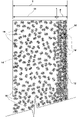
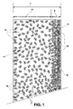
- FIG. 1 is a schematic, cross-sectional end view of one embodiment of a solid molecular composite electrolyte according to the invention.
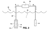
- FIG. 2 is a schematic view of one embodiment of a reactive metal-water battery system, which includes one embodiment of a solid molecular composite electrolyte according to the invention.
- FIG. 3 is a schematic representation of one embodiment of assymmetric crosslinking according to the invention, wherein crosslinking drops off dramatically inside of the skin of the molecular composite.
- FIG. 5 is a representation of another embodiment of a preferred polymer for inclusion in a skinned molecular composite according to the invention, having an organic backbone.
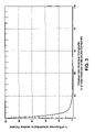
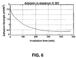
- FIG. 6 is a plot of Adhesive Strength vs. Irradiation Time according to embodiments of the invention for the outer “skinned” surface of the composite.
- This invention comprises a method of manufacturing molecular composite materials, preferably polymerceramic materials, for application as solid state battery electrolytes.
- the invention also comprises composited and “skinned” electrolytes that have dimensionally-stable and non-sticky surface(s) that improve the overall physical characteristics of the electrolyte while maintaining high conductivity.
- the polymer-ceramic composite electrolyte material 10 is treated by a radiation curing step or steps, to form a highly-stable outer layer or “skin” portion 12 on the composite material 10 that acts to protect the different physical properties of the bulk portion 14 of the composite product.
- the highly-stable crosslinked outer layer, on or near the surface of the molecular composite acts as a protective layer or barrier over part or all of the molecular composite that makes the product as a whole easily handleable and durable, in spite of the bulk of the composite product having the characteristics of being intractable and tacky in texture.
- the combination of the cured polymer surface with the composite's preferred semi-rigid silicate condensate framework results in a molecular composite that is dimensionally-stable and easy-to-handle as a whole, even though the interior bulk portion of the polymer is still generally fluid and tacky inside its framework. While contributing superior dimensional stability, durability, and processability to the product as a whole, the highly-stable, non-tacky, non-adhesive, and durable outer layer or portion is of a limited thickness, and preferably only on one side of the composite, so that the high conductivity of the polymer component is substantially preserved.
- the invented electrolyte preferably comprises a polymer-ceramic material formed by the catalyzed condensation of a ceramic precursor in the presence of a solvated polymer material.
- the preferred method comprises providing appropriate ceramic precursors and polymer for condensation into the molecular composite, wherein the ceramic precursors and polymers are appropriate for formation of a thin electrolytic membranes with high conductivity.
- the selected ceramic precursor is catalytically condensed in-situ with the solvated polymer in a solvent mixture that is miscible with both the polymer and the ceramic precursors. This initial mother liquor is ultrasonically treated for a short time and then formed into a membrane.
- the membrane then is preferably slowly cured at ambient temperature followed by a heated/vacuum drying step, resulting in a molecular composite 10 comprising a rigid ceramic framework 16 supporting a polymeric membrane 18 .
- a heated/vacuum drying step resulting in a molecular composite 10 comprising a rigid ceramic framework 16 supporting a polymeric membrane 18 .
- an additional curing step(s) is performed to alter the physical characteristics of the outer surface of the molecular composite while leaving the bulk of the molecular composite unaffected.
- the preferred surface-curing step is performed by exposing the electrolyte to UV radiation for a limited time and/or under limited UV frequency and/or power ranges.
- the preferred polymer(s) are therefore chosen to have properties that react to UV radiation in such a way as to form, under certain conditions, a thin, shallow skin of crosslinked polymer on the outside of the molecular composite.
- This skin 12 is preferably the outer layer of the molecular composite, specifically the outer layer of the polymer membrane 18 at the outer surface of the molecular composite 10 , that exhibits a high degree of crosslinking of the polymer molecules to themselves, while most of the polymer within the bulk portion 14 of the molecular composite remains un-crosslinked.
- the polymers that are substantially crosslinked ( 18 ′) preferably only occur at or near the outer surface, in other words, not deep into the molecular composite.
- the amount of crosslinking may vary within the “skin” layer, for example, ranging from a very high amount of crosslinking at the outer surface of the skin to less crosslinking at the inside of skin, it is preferred that the total depth of polymer comprising substantial crosslinking is only a small fraction of the depth of the molecular composite.
- a skin is purposely formed on the electrolyte that has a substantially different amount of crosslinking than the interior bulk portion of the polymerceramic material.
- the “surface-cured” electrolyte comprising surface-only crosslinking exhibits conductivity greater than or equal to 100 ⁇ S/cm at about 20–25° C., preferably in the range of 150–500 ⁇ S/cm or better.
- the resulting electrolyte maintains dimensional stability, that is, it does not flow, while subjected to pressures exerted upon it in the range of 475–525 g/cm 2 at about 20–25° C., wherein it is particularly desirable that the electrolyte not flow at a pressure of 500 g/cm 2 .
- the surface-cured molecular composite with it's improved texture and amount of tackiness, is well-adapted for further handling, storage, or preferably for direct inclusion in a variety of battery systems.
- Batteries made according to embodiments of the invention may include one or more electric-current-producing electrochemical cells, the cells comprising an anode, a cathode, and an electrolyte disposed between the anode and cathode and in ionically-conductive contact with the anode and cathode.
- anode 22 may be a atomic- or alloy-form metal from periodic table Group 1A elements, periodic table Group 2A elements, and mixtures thereof, and preferably, lithium or magnesium.
- An electrode 24 is placed in the cathode which comprises water 26 .
- the anode 22 may have an electrolyte 110 according to the invention attached to, and in ionically-conductive contact with, the anode outer surface, wherein the outer surface of the electrolyte 110 is the skin portion 112 .
- a conductive line 28 extends between the electrolyte and the electrode 24 in the water cathode 26 . Thus, battery discharge occurs through load 30 .
- the preferred polymers comprise UV-absorbing species positioned in the polymer structures to control/limit the penetration of the UV radiation to only the outer portion of the polymer, and, hence, the outer portion of the molecular composite, whereby the polymers in only that outer portion are crosslinked to any significant extent.
- the especially-preferred polymers are adapted so that the same polymer(s) may be used throughout the molecular composite, wherein added charge-carrying species such as Lithium remain mobile within the un-crosslinked portion of the polymer, for high conductivity at room temperature, while the same polymer, when crosslinked by UV radiation, produces a durable and non-adhesive skin.
- Polymers appropriate for the catalyzed condensation process may include, for example, polyphosphazenes, polysiloxanes, and/or mixtures thereof, or other polymers that allow high conductivity while also having components with high molar extinction coefficients in the UV range of radiation, which components are preferably aromatics, phenolics, or substituted versions of these components.
- Preferred polymer families are the polyphosphazenes, and polysiloxanes, and mixtures thereof, having the UV—high molar extinction coefficient moieties.
- Polyphosphazenes and all-organic-block polymers with phenolic or aromatic species are examples of polymers expected to exhibit the proper, shallow crosslinking performance upon exposure to UV radiation, while having bulk properties appropriate for application in battery electrolytes.
- Polyether containing phosphazenes polythioether containing phosphazenes, polyethers containing polysiloxanes, and polythioether containing polysiloxanes, or mixtures thereof, may be preferred for some battery embodiments.
- polyetherthiol containing containing phosphazenes polyetherthiol containing phosphazenes
- polyetherthiol containing polysiloxanes polyetherthiol containing polysiloxanes, and mixtures thereof, may be included in embodiments of the invention.
- the UV has little or no effect preferably in ⁇ 90% of the molecular composite, resulting in a density of crosslinking in the shallow skin portion rather than crosslinking throughout the bulk composite.
- FIG. 4 illustrates a preferred type of phosphazene 22 comprising a backbone 25 having associated ligands 27 covalently bonded to the backbone.
- Ligands 27 comprise ion carrying groups 32 (such as ethylene oxy or ethylene thiol groups, or mixed ethylene oxy and thiol groups) surrounding the backbone, which are further surrounded by hydrophobic, UV-light absorbing groups 34 preferably those that contain at least one aromatic moiety ( 36 ) per repeat unit, such as a substituted phenolic group. Examples of phosphazenes that may be used are described in U.S. Pat. No. 6,146,787.
- An especially-preferred phosphazene is based upon the phosphazene backbone, substituted with Triton-X-114TM (Aldrich Chemical Company) as a pendant group, yielding the homopolymer designated “MHT-1” by the inventors (similar to the polymer shown in FIG. 4 , except with S in place of the O bonded to the P center).
- an all organic-block co-polymer 42 may be used, which possesses blocks similar or the same as those of the preferred phosphazenes, that is, a backbone 45 surrounded by ion carrying groups 32 (particularly ethylene oxy, ethylene thiol, or mixed ethylene oxy and thiol groups), and further surrounded by hydrophobic, UV-light absorbing groups 34 preferably those that contain at least one aromatic moiety 36 per repeat unit, such as a substituted phenolic group.
- Crosslinking is affected by the radiation acting on the polymer, and no component is added to the polymer for initiating or effecting crosslinking, that is, no crosslinking initiator is used.
- the preferred ceramic precursors for the molecular composite of the invention are ones that are compatible with solvents that dissolve the polymers of the nature described above, for purposes of formation of the initial molecular composite.
- the ceramic precursor may be a metal alkoxide selected, for example, from silicon alkoxides, titanium alkoxides, zirconium alkoxides, aluminum alkoxides, and/or mixtures thereof.
- TEOS tetraethylorthosilicate
- TMOS tetramethylorthosilicate
- tetraisopropoxyorthotitanate zirconium n-butoxide butanol complex
- zirconium n-butyloxide aluminum tri-sec butoxide, and/or mixtures thereof are preferred.
- Lithium cations, sodium cations, and magnesium cations, or other charge-carrying species are included in the electrolyte. These species may be included according to conventional methods for inclusion of charge-carrying species in electrolytic composite materials.
- the molecular composite preferably in a thin membrane form, is irradiated by UV radiation.
- the outer face of the membrane preferably the one surface of the membrane exposed after the membrane is attached to an anode or after the membrane is formed in its mold, is irradiated, preferably with low-to-medium intensity ultra-violet radiation, until the desired curing is achieved.
- the low to medium range radiation comprises a low enough power output to cause crosslinking at the surface but with a minimum of deep radiation penetration, so as to best effect the highly asymmetric crosslinking as a function of depth into the composite, which asymmetric crosslinking is needed to form the skin.
- the low to medium radiation frequency is in the range of about 200–400 nm and the power is in the range of about 5–150 Watts power, and, more preferably, in the range of 5–50 Watts.
- the radiation step is preferably conducted for only a few hours, for example, less than about three hours, the sufficient time being a dependent function of the nature of the UV-absorbing species within a given polymer and the intensity of the UV photonic flux.
- UV radiation typically in the range of 200–400 nm is used for a short duration, for example, 20–120 minutes, to provide sufficient but not excessively-deep crosslinking in the polymer.
- this basic procedure may be supplemented by additional steps to render the material practical for particular uses.
- the preferred crosslinking at/near the outer surface of the polymer material in this invention may be characterized as the conversion of C—H bonds on the polymer component to C—C linkages by means of radiation-induced homolytic cleavage and subsequent radical-radical coupling.
- the this comprises crosslinking of alkyl or allyl groups from different polymer chains.
- irradiation time in minutes for adhesion to aluminum at 35° C. for various examples of UV radiation curing of molecular composite made of MHT-1 polymer (similar to FIG. 4 , with S in place of the O bonded to the P center) and TEOS.
- the irradiation was performed by a 100 W Hg lamp from Oriel Instrument Company. While adhesive strength of the “skinned” outer surface of the molecular composite rapidly declines vs. irradiation time, adhesion to the aluminum of uncrosslinked surfaces of the molecular composite (for example, a rear surface of the composite opposite the front, irradiated surface) remained unchanged regardless of time of irradiation of the front surface.
- the adhesion at “time zero” is generally the adhesion of the surface and of generally the entire bulk of the polymer before any radiation. During radiation, the bulk retains that initial adhesion, if it were exposed for measurement, but the surface adhesion declines. Adhesion reduction from greater than 2.5 KN/M 2 to about 1 KN/M 2 is rapid during the first approximately 100 minutes of radiation, and a more gradual reduction to about 0.5 KN/M 2 occurs from 100 minutes to several hundred minutes. In general, the preferred embodiments of the invention reduce adhesion of the electrolyte surface, as measured in this type of test by at least 50%, and preferably by at least 75%.
- the radiation-cured surface exhibits less than about 1 KN/M 2 while the bulk portion would continue to exhibit greater than 2 KN/M 2 .
- the curve shown in FIG. 6 illustrates that irradiation may be conducted for less than about 200 minutes, as the adhesion reduction benefit thereafter is minimal but, undesirably, crosslinking may increase thereafter in the bulk molecular composite. More preferably, irradiation is conducted for about 30–100 minutes at the conditions for the FIG. 6 examples.
- the preferred electrolyte made according to preferred methods has a crosslinked layer only equal to about 1%–20% of its thickness, preferably only about 2–10% and most preferably, about 2–3% of its thickness.
- the crosslinked skin is preferably highly crosslinked, and a steep crosslink density gradient exists in the molecular composite, starting at substantially crosslinked at the outer surface of the molecular composite, and approaching zero crosslinked density rapidly vs. distance into the molecular composite.
- the outer face of the composite, once sufficiently skinned by crosslinking is no longer significantly adhesive, that is, adhesion reduced by preferably about 50%, or adhesion reduced below about 1.5 KN/M2, and more preferably below about 1.0 KN/M2, in the aluminum adhesion test at about 35° C.
- the polymer in the bulk of the composite is substantially or completely un-crosslinked, and so is more fluid than the skin and is more highly conductive.
- a fluid polymer through preferably at least 80% of the thickness of the composite, or preferably 90–99% and most preferably 97–98% of the thickness of the composite, conductivity of the molecular composite is maintained overall at a high and commercially beneficial level.
- a molecular composite membrane may have a thickness T in the range of 15–60 ⁇ m.
- Such a membrane of this example thickness preferably may have a UV-crosslinked skin of a thickness S about 0.3–6 ⁇ m thick, with the bulk of the molecular composite (having thickness 13 ) being substantially un-crosslinked, and preferably not at all crosslinked.
- polymer crosslinking may be understood by one of skill in polymer art to mean occurrences of binding between different polymers chains, for example, as in the preferred embodiment, the formation of C—C bonds converted from two C—H groups, the carbons of which are from different polymer chains.
- polymer crosslinking There is expected to be variability in the thickness of the skin and the absolute number of crosslinking bonds in the skin formed by the preferred radiation surface-curing steps, depending upon what polymer(s) is/are chosen, what UV power, UV frequency, and duration are chosen.
- the skin it is expected that at the surface at least 80%, and preferably greater than 90%, of the polymers are crosslinked to at least one other adjacent polymer, and that these crosslinked polymers are crosslinked at a plurality of the C—H sites on each polymer to become C—C sites connecting previously-separate polymers. Given the many potential crosslinking allyl or alkyl C—H sites on each polymer, one may see that such an amount of crosslinking will substantially change the characteristics of the polymers and form a durable skin.
- This example illustrates a method for preparing a composite material according to the invention for application to Lithium/water batteries.
- An appropriate polymer such as poly[bis(phenoxytriethyleneoxy)phosphazene)] is dissolved in a polar solvent, such as tetrahydrofuran (THF), to form a 5–8 wt-% solution of polymer in the solvent.
- a polar solvent such as tetrahydrofuran (THF)
- THF tetrahydrofuran
- a catalytic amount of ammonia is then added to the polymer solution.
- the polymer solution and ceramic precursor are mixed together, and a lithium salt (such as lithium tetrafluoroborate) is added, for example, at about 6–8 wt-%, and the vessel is tightly sealed, so that no fluid can escape.
- a lithium salt such as lithium tetrafluoroborate
- the mixture is then immediately treated with ultrasonic waves for about thirty minutes. During this time, the condensation of the ceramic proceeds.
- the composite condensation mixture is then poured into Teflon® molds to form the desired shape and thickness of the molecular composite membrane.
- the composite material is then slowly dried, to remove solvent, in the molds under controlled conditions, such as 25° C., Argon atmosphere, for one to two days.
- the dried composite material is then fitted, on one of its surfaces, onto an anode such as a lithium metal strip, and removed from the mold.
- the remaining exposed surface of the molecular composite membrane is then irradiated at 256 nm (at 8 watts) for four hours to form a “skin” of crosslinked material on that exposed surface.
- the resulting cured composite membrane, with its already-attached anode, is handleable, non-adhesive, and, when connected to a suitable cathode material, is ready for use.
- Many effective cathode materials may be chosen, depending on the desired application.
- the preferred cathode being an inert metallic cathode for water applications, for example, for sea water applications.
- ambient temperature describes temperatures in the range from about 15° C. to about 45° C., preferably temperatures in the range from about 18° C. to about 35° C. and more preferably temperatures in the range from about 20° C. to about 25° C.
Abstract
Description
Claims (30)
Priority Applications (11)
| Application Number | Priority Date | Filing Date | Title |
|---|---|---|---|
| US10/194,376 US7008564B2 (en) | 2002-07-11 | 2002-07-11 | Cured composite materials for reactive metal battery electrolytes |
| KR1020057000407A KR100664819B1 (en) | 2002-07-11 | 2003-07-08 | A molecular composite electrolyte material, a method of manufacturing molecular composite electrolyte material, and batteries incorporating molecular composite electrolyte materials |
| MXPA05000154A MXPA05000154A (en) | 2002-07-11 | 2003-07-08 | Cured composite materials for reactive metal battery electrolytes. |
| CNB038164477A CN100382375C (en) | 2002-07-11 | 2003-07-08 | Cured composite materials for reactive metal battery electrolytes |
| PCT/US2003/021817 WO2004008558A2 (en) | 2002-07-11 | 2003-07-08 | Cured composite materials for reactive metal battery electrolytes |
| AU2003247864A AU2003247864A1 (en) | 2002-07-11 | 2003-07-08 | Cured composite materials for reactive metal battery electrolytes |
| BR0312520-3A BR0312520A (en) | 2002-07-11 | 2003-07-08 | Molecular Composite Electrolyte Material, Method for Molecular Composite Electrolyte, Battery, and Composite Solid Polymer Ceramic Electrolyte |
| EP03764567A EP1535354A4 (en) | 2002-07-11 | 2003-07-08 | Cured composite materials for reactive metal battery electrolytes |
| CA002491246A CA2491246C (en) | 2002-07-11 | 2003-07-08 | Cured composite materials for reactive metal battery electrolytes |
| JP2004521739A JP4164768B2 (en) | 2002-07-11 | 2003-07-08 | Cured composite materials for reactive metal battery electrolytes |
| HK06102811A HK1080220A1 (en) | 2002-07-11 | 2006-03-03 | Cured composite materials for reactive metal battery electrolytes |
Applications Claiming Priority (1)
| Application Number | Priority Date | Filing Date | Title |
|---|---|---|---|
| US10/194,376 US7008564B2 (en) | 2002-07-11 | 2002-07-11 | Cured composite materials for reactive metal battery electrolytes |
Publications (2)
| Publication Number | Publication Date |
|---|---|
| US20040009404A1 US20040009404A1 (en) | 2004-01-15 |
| US7008564B2 true US7008564B2 (en) | 2006-03-07 |
Family
ID=30114727
Family Applications (1)
| Application Number | Title | Priority Date | Filing Date |
|---|---|---|---|
| US10/194,376 Expired - Fee Related US7008564B2 (en) | 2002-07-11 | 2002-07-11 | Cured composite materials for reactive metal battery electrolytes |
Country Status (11)
| Country | Link |
|---|---|
| US (1) | US7008564B2 (en) |
| EP (1) | EP1535354A4 (en) |
| JP (1) | JP4164768B2 (en) |
| KR (1) | KR100664819B1 (en) |
| CN (1) | CN100382375C (en) |
| AU (1) | AU2003247864A1 (en) |
| BR (1) | BR0312520A (en) |
| CA (1) | CA2491246C (en) |
| HK (1) | HK1080220A1 (en) |
| MX (1) | MXPA05000154A (en) |
| WO (1) | WO2004008558A2 (en) |
Cited By (9)
| Publication number | Priority date | Publication date | Assignee | Title |
|---|---|---|---|---|
| US20050255385A1 (en) * | 2004-05-17 | 2005-11-17 | Harrup Mason K | Safe battery solvents |
| US20080131771A1 (en) * | 2006-12-04 | 2008-06-05 | 3M Innovative Properties Company | Curable electrolyte |
| US20110100091A1 (en) * | 2009-11-05 | 2011-05-05 | Battelle Energy Alliance, Llc | Taggants, method for forming a taggant, and a method for detecting an object |
| US8592628B2 (en) | 2010-06-03 | 2013-11-26 | Battelle Energy Alliance, Llc | Phosphazene additives |
| US20150165369A1 (en) * | 2012-06-26 | 2015-06-18 | Fujifilm Manufacturing Europe Bv | Process for Preparing Membranes |
| CN107408662A (en) * | 2015-03-02 | 2017-11-28 | 加利福尼亚大学董事会 | Micro cell |
| US10078893B2 (en) | 2010-12-29 | 2018-09-18 | Dia Imaging Analysis Ltd | Automatic left ventricular function evaluation |
| US10707531B1 (en) | 2016-09-27 | 2020-07-07 | New Dominion Enterprises Inc. | All-inorganic solvents for electrolytes |
| US10707526B2 (en) | 2015-03-27 | 2020-07-07 | New Dominion Enterprises Inc. | All-inorganic solvents for electrolytes |
Families Citing this family (8)
| Publication number | Priority date | Publication date | Assignee | Title |
|---|---|---|---|---|
| WO2001000310A2 (en) * | 1999-06-08 | 2001-01-04 | Bechtel Bwxt Idaho, Llc | Plasma reforming and partial oxidation of hydrocarbon fuel vapor to produce synthesis gas and/or hydrogen gas |
| US7008564B2 (en) * | 2002-07-11 | 2006-03-07 | Battelle Energy Alliance, Llc | Cured composite materials for reactive metal battery electrolytes |
| US8153435B1 (en) | 2005-03-30 | 2012-04-10 | Tracer Detection Technology Corp. | Methods and articles for identifying objects using encapsulated perfluorocarbon tracers |
| JP5089595B2 (en) | 2006-09-11 | 2012-12-05 | 旭化成株式会社 | Novel polymer electrolytes and electrochemical devices |
| US7658773B2 (en) * | 2006-09-29 | 2010-02-09 | Qimonda Ag | Method for fabricating a solid electrolyte memory device and solid electrolyte memory device |
| KR101339704B1 (en) | 2011-09-01 | 2013-12-10 | 재단법인대구경북과학기술원 | Polymer Electrolyte for Photo Sensitized Solar Cell, Photo Sensitized Solar Cell Comprising the Same, and the Preparation Thereof |
| CN111909381B (en) * | 2020-09-11 | 2021-06-15 | 东部超导科技(苏州)有限公司 | Ultraviolet crosslinking polyphosphazene, preparation method thereof, composite coating low-temperature measurement optical fiber and preparation method thereof |
| CN113347828B (en) * | 2021-05-31 | 2023-03-17 | Oppo广东移动通信有限公司 | Polymer ceramic housing and electronic device |
Citations (15)
| Publication number | Priority date | Publication date | Assignee | Title |
|---|---|---|---|---|
| US4722877A (en) | 1986-09-15 | 1988-02-02 | Eltron Research, Inc. | Long cycle life solid-state solid polymer electrolyte cells |
| US5061581A (en) | 1990-02-07 | 1991-10-29 | Sri International | Novel solid polymer electrolytes |
| US5166009A (en) * | 1991-03-28 | 1992-11-24 | The United States Of America As Represented By The Secretary Of The Navy | Mixed polymer electrolyte and mixed polymer electrolyte battery |
| US5190698A (en) * | 1991-04-15 | 1993-03-02 | Eastman Kodak Company | Poly(alkylene oxide)vinyl carboxylic ester containing polymer/inorganic oxide composites and methods of making |
| US5219679A (en) | 1991-01-17 | 1993-06-15 | Eic Laboratories, Inc. | Solid electrolytes |
| US5414025A (en) * | 1992-09-30 | 1995-05-09 | The Penn State Research Foundation | Method of crosslinking of solid state battery electrolytes by ultraviolet radiation |
| JPH07320782A (en) * | 1994-05-20 | 1995-12-08 | Sanyo Electric Co Ltd | Solid electrolytic secondary battery |
| US5567783A (en) | 1995-03-07 | 1996-10-22 | The Penn State Research Foundation | Polyphosphazenes bearing crown ether and related podand side groups as solid solvents for ionic conduction |
| US5609974A (en) | 1995-08-04 | 1997-03-11 | Battery Engineering, Inc. | Rechargeable battery polymeric electrolyte |
| USH1666H (en) | 1995-09-15 | 1997-07-01 | The United States Of America As Represented By The Secretary Of The Navy | Method of cross-linking poly(ethylene oxide) and poly[oxymethylene-oligo(oxyethylene)] with ultraviolet radiation |
| US5965299A (en) * | 1997-06-23 | 1999-10-12 | North Carolina State University | Composite electrolyte containing surface modified fumed silica |
| US6020087A (en) | 1998-01-30 | 2000-02-01 | Valence Technology, Inc. | Polymer electrolytes containing lithiated fillers |
| US6146787A (en) * | 1998-11-11 | 2000-11-14 | Bechtel Bwxt Idaho, Llc | Solid polymer battery electrolyte and reactive metal-water battery |
| US6190806B1 (en) | 1997-08-21 | 2001-02-20 | The University Of Dayton | Solid composite electrolytes for lithium batteries |
| US6201100B1 (en) | 1997-12-19 | 2001-03-13 | Moltech Corporation | Electroactive, energy-storing, highly crosslinked, polysulfide-containing organic polymers and methods for making same |
Family Cites Families (6)
| Publication number | Priority date | Publication date | Assignee | Title |
|---|---|---|---|---|
| GB9027804D0 (en) * | 1990-12-21 | 1991-02-13 | Ici Plc | Solid electrolytes |
| US5695873A (en) * | 1995-06-05 | 1997-12-09 | The University Of Dayton | Polymer-ceramic composite electrolytes |
| JP2891191B2 (en) * | 1996-06-28 | 1999-05-17 | 日本電気株式会社 | Magneto-optical disk drive |
| US6645675B1 (en) * | 1999-09-02 | 2003-11-11 | Lithium Power Technologies, Inc. | Solid polymer electrolytes |
| US6544690B1 (en) * | 2000-07-28 | 2003-04-08 | Bechtel Bwxt Idaho, Llc | Self-doped molecular composite battery electrolytes |
| US7008564B2 (en) * | 2002-07-11 | 2006-03-07 | Battelle Energy Alliance, Llc | Cured composite materials for reactive metal battery electrolytes |
-
2002
- 2002-07-11 US US10/194,376 patent/US7008564B2/en not_active Expired - Fee Related
-
2003
- 2003-07-08 AU AU2003247864A patent/AU2003247864A1/en not_active Abandoned
- 2003-07-08 EP EP03764567A patent/EP1535354A4/en not_active Withdrawn
- 2003-07-08 WO PCT/US2003/021817 patent/WO2004008558A2/en active Application Filing
- 2003-07-08 CN CNB038164477A patent/CN100382375C/en not_active Expired - Fee Related
- 2003-07-08 JP JP2004521739A patent/JP4164768B2/en not_active Expired - Fee Related
- 2003-07-08 KR KR1020057000407A patent/KR100664819B1/en not_active IP Right Cessation
- 2003-07-08 BR BR0312520-3A patent/BR0312520A/en not_active IP Right Cessation
- 2003-07-08 CA CA002491246A patent/CA2491246C/en not_active Expired - Fee Related
- 2003-07-08 MX MXPA05000154A patent/MXPA05000154A/en active IP Right Grant
-
2006
- 2006-03-03 HK HK06102811A patent/HK1080220A1/en not_active IP Right Cessation
Patent Citations (15)
| Publication number | Priority date | Publication date | Assignee | Title |
|---|---|---|---|---|
| US4722877A (en) | 1986-09-15 | 1988-02-02 | Eltron Research, Inc. | Long cycle life solid-state solid polymer electrolyte cells |
| US5061581A (en) | 1990-02-07 | 1991-10-29 | Sri International | Novel solid polymer electrolytes |
| US5219679A (en) | 1991-01-17 | 1993-06-15 | Eic Laboratories, Inc. | Solid electrolytes |
| US5166009A (en) * | 1991-03-28 | 1992-11-24 | The United States Of America As Represented By The Secretary Of The Navy | Mixed polymer electrolyte and mixed polymer electrolyte battery |
| US5190698A (en) * | 1991-04-15 | 1993-03-02 | Eastman Kodak Company | Poly(alkylene oxide)vinyl carboxylic ester containing polymer/inorganic oxide composites and methods of making |
| US5414025A (en) * | 1992-09-30 | 1995-05-09 | The Penn State Research Foundation | Method of crosslinking of solid state battery electrolytes by ultraviolet radiation |
| JPH07320782A (en) * | 1994-05-20 | 1995-12-08 | Sanyo Electric Co Ltd | Solid electrolytic secondary battery |
| US5567783A (en) | 1995-03-07 | 1996-10-22 | The Penn State Research Foundation | Polyphosphazenes bearing crown ether and related podand side groups as solid solvents for ionic conduction |
| US5609974A (en) | 1995-08-04 | 1997-03-11 | Battery Engineering, Inc. | Rechargeable battery polymeric electrolyte |
| USH1666H (en) | 1995-09-15 | 1997-07-01 | The United States Of America As Represented By The Secretary Of The Navy | Method of cross-linking poly(ethylene oxide) and poly[oxymethylene-oligo(oxyethylene)] with ultraviolet radiation |
| US5965299A (en) * | 1997-06-23 | 1999-10-12 | North Carolina State University | Composite electrolyte containing surface modified fumed silica |
| US6190806B1 (en) | 1997-08-21 | 2001-02-20 | The University Of Dayton | Solid composite electrolytes for lithium batteries |
| US6201100B1 (en) | 1997-12-19 | 2001-03-13 | Moltech Corporation | Electroactive, energy-storing, highly crosslinked, polysulfide-containing organic polymers and methods for making same |
| US6020087A (en) | 1998-01-30 | 2000-02-01 | Valence Technology, Inc. | Polymer electrolytes containing lithiated fillers |
| US6146787A (en) * | 1998-11-11 | 2000-11-14 | Bechtel Bwxt Idaho, Llc | Solid polymer battery electrolyte and reactive metal-water battery |
Non-Patent Citations (11)
Cited By (17)
| Publication number | Priority date | Publication date | Assignee | Title |
|---|---|---|---|---|
| US7285362B2 (en) | 2004-05-17 | 2007-10-23 | Battelle Energy Alliance, Llc | Safe battery solvents |
| US20080096056A1 (en) * | 2004-05-17 | 2008-04-24 | Harrup Mason K | Safe battery solvents |
| US20050255385A1 (en) * | 2004-05-17 | 2005-11-17 | Harrup Mason K | Safe battery solvents |
| US20080131771A1 (en) * | 2006-12-04 | 2008-06-05 | 3M Innovative Properties Company | Curable electrolyte |
| US7864397B2 (en) | 2006-12-04 | 2011-01-04 | 3M Innovative Properties Company | Curable electrolyte |
| US20110100091A1 (en) * | 2009-11-05 | 2011-05-05 | Battelle Energy Alliance, Llc | Taggants, method for forming a taggant, and a method for detecting an object |
| US8124414B2 (en) | 2009-11-05 | 2012-02-28 | Battelle Energy Alliance, Llc | Taggants, method for forming a taggant, and a method for detecting an object |
| US8592628B2 (en) | 2010-06-03 | 2013-11-26 | Battelle Energy Alliance, Llc | Phosphazene additives |
| US10078893B2 (en) | 2010-12-29 | 2018-09-18 | Dia Imaging Analysis Ltd | Automatic left ventricular function evaluation |
| US20150165369A1 (en) * | 2012-06-26 | 2015-06-18 | Fujifilm Manufacturing Europe Bv | Process for Preparing Membranes |
| US9579609B2 (en) * | 2012-06-26 | 2017-02-28 | Fujifilm Manufacturing Europe Bv | Process for preparing membranes |
| CN107408662A (en) * | 2015-03-02 | 2017-11-28 | 加利福尼亚大学董事会 | Micro cell |
| US10566617B2 (en) * | 2015-03-02 | 2020-02-18 | The Regents Of The University Of California | Microbattery |
| CN107408662B (en) * | 2015-03-02 | 2021-09-07 | 加利福尼亚大学董事会 | Microbattery and method for producing a microbattery |
| US10707526B2 (en) | 2015-03-27 | 2020-07-07 | New Dominion Enterprises Inc. | All-inorganic solvents for electrolytes |
| US11271248B2 (en) | 2015-03-27 | 2022-03-08 | New Dominion Enterprises, Inc. | All-inorganic solvents for electrolytes |
| US10707531B1 (en) | 2016-09-27 | 2020-07-07 | New Dominion Enterprises Inc. | All-inorganic solvents for electrolytes |
Also Published As
| Publication number | Publication date |
|---|---|
| CA2491246C (en) | 2009-12-29 |
| WO2004008558A3 (en) | 2004-06-10 |
| KR100664819B1 (en) | 2007-01-04 |
| JP2005531685A (en) | 2005-10-20 |
| US20040009404A1 (en) | 2004-01-15 |
| AU2003247864A8 (en) | 2004-02-02 |
| AU2003247864A1 (en) | 2004-02-02 |
| CA2491246A1 (en) | 2004-01-22 |
| BR0312520A (en) | 2005-04-19 |
| KR20050032570A (en) | 2005-04-07 |
| JP4164768B2 (en) | 2008-10-15 |
| EP1535354A4 (en) | 2007-10-31 |
| EP1535354A2 (en) | 2005-06-01 |
| CN1669173A (en) | 2005-09-14 |
| WO2004008558A2 (en) | 2004-01-22 |
| MXPA05000154A (en) | 2005-04-11 |
| HK1080220A1 (en) | 2006-04-21 |
| CN100382375C (en) | 2008-04-16 |
Similar Documents
| Publication | Publication Date | Title |
|---|---|---|
| US7008564B2 (en) | Cured composite materials for reactive metal battery electrolytes | |
| US6284412B1 (en) | Hybrid polymeric electrolyte and non-aqueous electrochemical device comprising the same | |
| US6299653B1 (en) | Hybrid electrolyte, method for manufacturing the same, and method for manufacturing electrochemical element using the same | |
| US6544690B1 (en) | Self-doped molecular composite battery electrolytes | |
| EP0760383B1 (en) | Ion-conductive film and precursor film therefor | |
| KR20030077453A (en) | Gel electrolyte, process for producing the same, and use thereof | |
| JP3422627B2 (en) | Crosslinked polymer solid electrolyte and battery | |
| JP2008222957A (en) | Porous membrane comprising alkyleneoxide polymer and polymer solid electrolyte using the same as base material | |
| JP3318634B2 (en) | Semi-solid electrolyte secondary battery | |
| US20030205322A2 (en) | Method for Manufacturing Solid Polymer Electrolyte/Electrode Composites, Battery Produced Using the Method and Method for Producing the Same | |
| JPH1186627A (en) | Polymer solid electrolyte and its use | |
| KR100337660B1 (en) | Method for fabricating polymer electrolyte composite and Li polymer secondary battery using the same | |
| CA2248866A1 (en) | Ion conductive laminate and production method and use thereof | |
| JP3667005B2 (en) | Gel-based electrolyte and method for producing electrochemical element | |
| KR102468266B1 (en) | A separator and a method for manufacturing the same | |
| JPH09320617A (en) | Manufacture of polymer solid electrolyte | |
| JPH09293519A (en) | Electrolyte thin film and battery using this electrolyte thin film | |
| JP2003100349A (en) | Method of making adhesive polymer gel electrolyte | |
| JP3581774B2 (en) | Aprotic electrolyte thin film and method for producing the same | |
| Martinez-Cisneros et al. | Polymer electrolytes based on POE and Na-TFS salt for all-solid-state batteries | |
| KR20230049242A (en) | Secondary battery comprising gel polymer electrolyte, and method for preparing the same | |
| JPH113717A (en) | Hybrid electrolyte and battery | |
| JP3028824B2 (en) | Immobilized liquid film conductor and battery using the same | |
| JP2007035646A (en) | Polymer gel electrolyte and method of manufacturing same |
Legal Events
| Date | Code | Title | Description |
|---|---|---|---|
| AS | Assignment |
Owner name: BECHTEL BWXT IDAHO, LLC, IDAHO Free format text: ASSIGNMENT OF ASSIGNORS INTEREST;ASSIGNORS:HARRUP, MASON K.;STEWART, FREDERICK F.;PETERSON, ERIC S.;REEL/FRAME:013108/0218 Effective date: 20020711 |
|
| AS | Assignment |
Owner name: ENERGY, UNITED STATES DEPARTMENT OF, DISTRICT OF C Free format text: CONFIRMATORY LICENSE;ASSIGNOR:BECHTEL BWXT IDAHO, INC.;REEL/FRAME:014170/0816 Effective date: 20030423 |
|
| AS | Assignment |
Owner name: BATTELLE ENERGY ALLIANCE, LLC, IDAHO Free format text: ASSIGNMENT OF ASSIGNORS INTEREST;ASSIGNOR:BECHTEL BWXT IDAHO, LLC;REEL/FRAME:016226/0765 Effective date: 20050201 Owner name: BATTELLE ENERGY ALLIANCE, LLC,IDAHO Free format text: ASSIGNMENT OF ASSIGNORS INTEREST;ASSIGNOR:BECHTEL BWXT IDAHO, LLC;REEL/FRAME:016226/0765 Effective date: 20050201 |
|
| FPAY | Fee payment |
Year of fee payment: 4 |
|
| FPAY | Fee payment |
Year of fee payment: 8 |
|
| FEPP | Fee payment procedure |
Free format text: MAINTENANCE FEE REMINDER MAILED (ORIGINAL EVENT CODE: REM.) |
|
| LAPS | Lapse for failure to pay maintenance fees |
Free format text: PATENT EXPIRED FOR FAILURE TO PAY MAINTENANCE FEES (ORIGINAL EVENT CODE: EXP.) |
|
| STCH | Information on status: patent discontinuation |
Free format text: PATENT EXPIRED DUE TO NONPAYMENT OF MAINTENANCE FEES UNDER 37 CFR 1.362 |
|
| FP | Lapsed due to failure to pay maintenance fee |
Effective date: 20180307 |