US7012815B2 - Computer systems - Google Patents
Computer systems Download PDFInfo
- Publication number
- US7012815B2 US7012815B2 US10/171,809 US17180902A US7012815B2 US 7012815 B2 US7012815 B2 US 7012815B2 US 17180902 A US17180902 A US 17180902A US 7012815 B2 US7012815 B2 US 7012815B2
- Authority
- US
- United States
- Prior art keywords
- shelf
- server
- blade
- enclosure
- information processing
- Prior art date
- Legal status (The legal status is an assumption and is not a legal conclusion. Google has not performed a legal analysis and makes no representation as to the accuracy of the status listed.)
- Expired - Lifetime, expires
Links
Images


Classifications
-
- G—PHYSICS
- G06—COMPUTING; CALCULATING OR COUNTING
- G06F—ELECTRIC DIGITAL DATA PROCESSING
- G06F1/00—Details not covered by groups G06F3/00 - G06F13/00 and G06F21/00
- G06F1/16—Constructional details or arrangements
- G06F1/18—Packaging or power distribution
- G06F1/183—Internal mounting support structures, e.g. for printed circuit boards, internal connecting means
- G06F1/187—Mounting of fixed and removable disk drives
-
- G—PHYSICS
- G06—COMPUTING; CALCULATING OR COUNTING
- G06F—ELECTRIC DIGITAL DATA PROCESSING
- G06F21/00—Security arrangements for protecting computers, components thereof, programs or data against unauthorised activity
- G06F21/30—Authentication, i.e. establishing the identity or authorisation of security principals
- G06F21/31—User authentication
-
- G—PHYSICS
- G06—COMPUTING; CALCULATING OR COUNTING
- G06F—ELECTRIC DIGITAL DATA PROCESSING
- G06F21/00—Security arrangements for protecting computers, components thereof, programs or data against unauthorised activity
- G06F21/50—Monitoring users, programs or devices to maintain the integrity of platforms, e.g. of processors, firmware or operating systems
- G06F21/55—Detecting local intrusion or implementing counter-measures
-
- G—PHYSICS
- G06—COMPUTING; CALCULATING OR COUNTING
- G06F—ELECTRIC DIGITAL DATA PROCESSING
- G06F21/00—Security arrangements for protecting computers, components thereof, programs or data against unauthorised activity
- G06F21/60—Protecting data
- G06F21/62—Protecting access to data via a platform, e.g. using keys or access control rules
- G06F21/629—Protecting access to data via a platform, e.g. using keys or access control rules to features or functions of an application
-
- G—PHYSICS
- G11—INFORMATION STORAGE
- G11B—INFORMATION STORAGE BASED ON RELATIVE MOVEMENT BETWEEN RECORD CARRIER AND TRANSDUCER
- G11B33/00—Constructional parts, details or accessories not provided for in the other groups of this subclass
- G11B33/12—Disposition of constructional parts in the apparatus, e.g. of power supply, of modules
- G11B33/125—Disposition of constructional parts in the apparatus, e.g. of power supply, of modules the apparatus comprising a plurality of recording/reproducing devices, e.g. modular arrangements, arrays of disc drives
- G11B33/127—Mounting arrangements of constructional parts onto a chassis
- G11B33/128—Mounting arrangements of constructional parts onto a chassis of the plurality of recording/reproducing devices, e.g. disk drives, onto a chassis
-
- H—ELECTRICITY
- H04—ELECTRIC COMMUNICATION TECHNIQUE
- H04L—TRANSMISSION OF DIGITAL INFORMATION, e.g. TELEGRAPHIC COMMUNICATION
- H04L63/00—Network architectures or network communication protocols for network security
- H04L63/08—Network architectures or network communication protocols for network security for authentication of entities
- H04L63/083—Network architectures or network communication protocols for network security for authentication of entities using passwords
-
- H—ELECTRICITY
- H04—ELECTRIC COMMUNICATION TECHNIQUE
- H04L—TRANSMISSION OF DIGITAL INFORMATION, e.g. TELEGRAPHIC COMMUNICATION
- H04L63/00—Network architectures or network communication protocols for network security
- H04L63/14—Network architectures or network communication protocols for network security for detecting or protecting against malicious traffic
- H04L63/1408—Network architectures or network communication protocols for network security for detecting or protecting against malicious traffic by monitoring network traffic
- H04L63/1416—Event detection, e.g. attack signature detection
-
- H—ELECTRICITY
- H05—ELECTRIC TECHNIQUES NOT OTHERWISE PROVIDED FOR
- H05K—PRINTED CIRCUITS; CASINGS OR CONSTRUCTIONAL DETAILS OF ELECTRIC APPARATUS; MANUFACTURE OF ASSEMBLAGES OF ELECTRICAL COMPONENTS
- H05K7/00—Constructional details common to different types of electric apparatus
- H05K7/14—Mounting supporting structure in casing or on frame or rack
- H05K7/1422—Printed circuit boards receptacles, e.g. stacked structures, electronic circuit modules or box like frames
- H05K7/1424—Card cages
- H05K7/1425—Card cages of standardised dimensions, e.g. 19"-subrack
-
- H—ELECTRICITY
- H05—ELECTRIC TECHNIQUES NOT OTHERWISE PROVIDED FOR
- H05K—PRINTED CIRCUITS; CASINGS OR CONSTRUCTIONAL DETAILS OF ELECTRIC APPARATUS; MANUFACTURE OF ASSEMBLAGES OF ELECTRICAL COMPONENTS
- H05K7/00—Constructional details common to different types of electric apparatus
- H05K7/14—Mounting supporting structure in casing or on frame or rack
- H05K7/1485—Servers; Data center rooms, e.g. 19-inch computer racks
- H05K7/1488—Cabinets therefor, e.g. chassis or racks or mechanical interfaces between blades and support structures
- H05K7/1489—Cabinets therefor, e.g. chassis or racks or mechanical interfaces between blades and support structures characterized by the mounting of blades therein, e.g. brackets, rails, trays
-
- G—PHYSICS
- G06—COMPUTING; CALCULATING OR COUNTING
- G06F—ELECTRIC DIGITAL DATA PROCESSING
- G06F2221/00—Indexing scheme relating to security arrangements for protecting computers, components thereof, programs or data against unauthorised activity
- G06F2221/21—Indexing scheme relating to G06F21/00 and subgroups addressing additional information or applications relating to security arrangements for protecting computers, components thereof, programs or data against unauthorised activity
- G06F2221/2119—Authenticating web pages, e.g. with suspicious links
-
- G—PHYSICS
- G06—COMPUTING; CALCULATING OR COUNTING
- G06F—ELECTRIC DIGITAL DATA PROCESSING
- G06F2221/00—Indexing scheme relating to security arrangements for protecting computers, components thereof, programs or data against unauthorised activity
- G06F2221/21—Indexing scheme relating to G06F21/00 and subgroups addressing additional information or applications relating to security arrangements for protecting computers, components thereof, programs or data against unauthorised activity
- G06F2221/2137—Time limited access, e.g. to a computer or data
-
- G—PHYSICS
- G06—COMPUTING; CALCULATING OR COUNTING
- G06F—ELECTRIC DIGITAL DATA PROCESSING
- G06F2221/00—Indexing scheme relating to security arrangements for protecting computers, components thereof, programs or data against unauthorised activity
- G06F2221/21—Indexing scheme relating to G06F21/00 and subgroups addressing additional information or applications relating to security arrangements for protecting computers, components thereof, programs or data against unauthorised activity
- G06F2221/2141—Access rights, e.g. capability lists, access control lists, access tables, access matrices
-
- G—PHYSICS
- G06—COMPUTING; CALCULATING OR COUNTING
- G06F—ELECTRIC DIGITAL DATA PROCESSING
- G06F2221/00—Indexing scheme relating to security arrangements for protecting computers, components thereof, programs or data against unauthorised activity
- G06F2221/21—Indexing scheme relating to G06F21/00 and subgroups addressing additional information or applications relating to security arrangements for protecting computers, components thereof, programs or data against unauthorised activity
- G06F2221/2149—Restricted operating environment
Definitions
- the present invention relates to computer systems, in particular to computer systems suitable for multiprocessor systems, for example multiprocessor server systems.
- One application for the present invention relates to high reliability systems, for example, computer server systems for telecommunications applications.
- high reliability systems for example, computer server systems for telecommunications applications.
- Various approaches have been taken to providing such high-performance, high reliability systems.
- Such systems are designed around providing redundant resources so that if one component of the system develops a fault, the system remains operation using the redundant resources. Redundant operation can be provided by means of special purposes lockstep-operating multi-processor systems.
- Such systems are typically rack mountable, with each processor system typically occupying a shelf in the rack.
- the trend in recent times is to make the computers with shallower form factors. This means that more computers can be located in a rack. This has the advantage of increasing the processing density within the racks, and also the advantage of reducing the distance between the computer systems.
- One aspect of the invention provides an information processing module comprising an enclosure that encloses a processor subsystem including a processor, memory and a storage device.
- the information processing module is configured as a field replaceable unit removably receivable in a carrier.
- the carrier includes at least a power supply module operable to supply DC operating power, a switch module operable to distribute information signals, and a service processor module operable to process system management signals.
- the information processing module includes an information processing module connector accessible externally to the enclosure and configured to connect with a corresponding information processing module receiving carrier connector on the carrier.
- the processor subsystem is thereby operable to receive DC power from the power supply module, to communicate information signals with the switch module and to communicate system management signals with the service processor module.
- the information processing module can be kept compact and inexpensive.
- the information processing module By configuring the information processing module as a field replaceable unit, a faulty information processing module can readily be replaced.
- Providing an enclosure that fully encloses the information processing subsytem means that the information processing module is robust and that replacement of the faulty unit does not need to be performed by a skilled engineer.
- the service controller is operable to communicate system management signals with the service processor module.
- a serial interface can, for example, provide for communicating system management signals with the service processor module.
- One or more Ethernet interfaces can be provided to communicate information signals with the switch module for the distribution of the information signals. Maintenance is facilitated by configuring the information processing module to be hot-swappable.
- the information processing modules can have a slab-like form and be configured as blades for side-by-side mounting in a carrier with the connector being located on a narrow end face of the enclosure.
- Cooling of the information processing module can be achieved by arranging ventilation openings on the face of the information processing module enclosure on which the connector is located and on an opposing face thereof and providing a fan within the module to force cooling air between the ventilation openings of the opposing faces.
- An injector lever mechanism can be provided to facilitate insertion and removal of the information processing module.
- a metal or metal coated enclosure can provide electromagnetic interference shielding for the components contained therein.
- the processor of an information processing module is operable as a server.
- a carrier that includes a carrier enclosure providing one or more information processing module receiving locations, each location being configured removably to receive an information processing module.
- the carrier includes one or more power supply modules operable to supply DC operating power, one or more switch modules operable to distribute information signals, and one or more service processor modules operate to process system management signals.
- Each information processing module receiving location includes one or more information processing module receiving carrier connectors configured to connect to one or more corresponding information processing modules connectors on a received information processing module. The connectors enable the supply of DC power from the power supply module(s) to a received information processing module, communication of information signals between the switch module(s) and the received information processing module and communication of system management signals between the service processor module(s) and the received information processing module.
- One or more power supply module receiving locations can be configured removably to receive a field replaceable power supply, each power supply receiving location including power supply receiving carrier connectors configured to connect with corresponding power supply connectors on a received power supply module.
- One or more switch module receiving locations can be configured removably to receive a field replaceable switch module, each switch module receiving location including switch module receiving carrier connectors configured to connect with corresponding switch connectors on a received switch module.
- At least one service processor module receiving location can be configured removably to receive a field replaceable, service processor module, the switch module receiving location including service processor module receiving carrier connectors configured to connect with corresponding service processor module connectors on a received service processor module.
- connection plane can carry the connectors, the connection plane also carrying conductive paths interconnecting the carrier connectors for carrying power, information signals and system management signals.
- connection plane can form a midplane with the information processing module receiving locations at a first side of the midplane and locations for receiving the power supply module, the switch module and the service processor module at a second side of the midplane.
- the midplane can be configured as a printed circuit board with conductive paths in the form of tracks on the midplane.
- the midplane can include openings configured to permit a flow of cooling air to pass through the midplane.
- a carrier including a chassis defining a carrier enclosure with a first face and a second face.
- a connector plane is located inside the carrier enclosure between the first and second faces.
- a first field replaceable receiving location has an opening in the first face, the connector plane carrying a first connector on a first surface thereof for connecting with a corresponding connector on a field replaceable unit when received in the first field replaceable unit receiving location.
- a second field replaceable receiving location has an opening in the second face, the connector plane carrying a second connector on a second surface thereof connecting with a corresponding connector on a field replaceable unit when received in the second field replaceable unit receiving location.
- the connector plane further carries conductive paths interconnecting the first and second connectors.
- the connector plane is passive and does not carry any active components.
- the midplane can include openings configured to permit a flow of cooling air to pass through the midplane.
- a further aspect of the invention provides a carrier comprising a chassis defining a carrier enclosure with a first face and a second face and a passive midplane located inside the carrier enclosure between the first and second faces.
- a first field replaceable receiving location has an opening in the first face, the connector plane carrying a first connector on a first surface thereof for connecting with a corresponding connector on a field replaceable unit when received in the first field replaceable unit receiving location.
- a second field replaceable receiving location has an opening in the second face, the connector plane carrying a second connector on a second surface thereof for connecting with a corresponding connector on a field replaceable unit when received in the second field replaceable unit receiving location.
- the connector plane further carries conductive paths interconnecting the first and second connectors and has ventilation openings to permit a flow of cooling air between the first and second faces.
- Each field replaceable unit is provided with an enclosure with openings in opposite faces for the passage of cooling air.
- Each field replaceable unit further includes a fan unit operable to force cooling air through the field replaceable unit.
- the openings in the field replaceable units can be arranged to cooperate with the openings in the midplane such that airflow passes between the first and second faces of the carrier via said at least one first field replaceable unit, openings in the midplane and said at least one second replaceable unit, the cooling air being driven by the fans in the field replaceable units.
- the chassis with the carrier plane can be totally passive, with the cooling being provided by the field replaceable units. This provides advantages in terms of cost, reliability and ease of maintenance of the system.
- the carrier can be configured as a rack mountable shelf with suitable fixings for mounting the carrier in a racking system.
- a first face of the carrier enclosure can form a front of the rack mountable shelf and a second face of the carrier enclosure can form the rear of the rack mountable shelf, whereby cooling air can be taken from the front of the shelf and be expelled from the rear of the shelf.
- a further aspect of the invention provides a rack mountable shelf configured to support a plurality of field replaceable units in the form of server cartridges that each include at least one server processor, the rack mountable shelf being configured to provide communal services for the server cartridges, including at least one of supplying DC operating power to the server cartridges, distributing information signals between the server cartridges and processing system management signals for the server cartridges.
- Each of the server cartridges can be slideably received in a respective one of a series of server cartridge receiving locations arrayed side by side along the front of the shelf.
- the server cartridges can be configured as thin blades to provide a high server density. For example, 16 server cartridge receiving locations can be provided across the front of the shelf.
- the supply of DC operating power to the server cartridges can be provided by one or more field replaceable power supply units (e.g. two redundantly configured power supply units) mounted in the shelf.
- the distribution of information signals between the server cartridges can be provided by one or more switch units (e.g. two redundantly configured switch units) mounted in the shelf.
- the processing of system management signals for the information processing modules is provided by one or more field replaceable service processor units (e.g. one service processor unit) mounted in the shelf.
- Each of the power supply, switch and service processor units can be slideable received in a respective receiving location at the rear of the shelf.
- a midplane including connectors with conductive paths therebetween can provide power, information signal and system management signal connections between received field replaceable units.
- a computer server system can be formed from at least one rack mountable shelf as set out above.
- a rack mounted computer server system can be formed from a rack frame and, mounted in the rack frame, at least one shelf as set out above.
- the method comprises providing a rack mountable shelf configured to support a plurality of field replaceable units in the form of server cartridges that each include at least one server processor, and providing communal services for the server cartridges in the shelf, the communal services including at least one of supplying DC operating power to the server cartridges, distributing information signals between the server cartridges, and processing system management signals for the server cartridges.
- FIG. 1 is a schematic representation of an architecture of a multiprocessor system for supporting a web site
- FIG. 2 is a schematic representation of a racking system incorporating an example of a carrier in the form of a rack-mountable shelf according to a first example;
- FIG. 3 is a front view of an example of a carrier in the form of a shelf of FIG. 2 ;
- FIG. 4 is a rear view of an example of the shelf of FIG. 2 ;
- FIGS. 5A , 5 B and 5 C are schematic perspective views and a schematic exploded view respectively of an example of an information processing cartridge for mounting in the shelf of FIG. 2 ;
- FIG. 5D is a schematic perspective view of an example of an information processing cartridge for mounting in the shelf of FIG. 2 ;
- FIG. 6 is a schematic perspective view of an example of a combined switch and service processor module for mounting in the shelf of FIG. 2 ;
- FIG. 7 is a schematic perspective view of an example of a power supply module for mounting in the shelf of FIG. 2 ;
- FIGS. 8A , 8 B and 8 C are a schematic plan view and schematic perspective views, respectively, of an example of the chassis and midplane of the shelf of FIG. 2 ;
- FIGS. 9A , 9 B and 9 C are schematic front, top and rear views, respectively, of an example of a midplane of the shelf of FIG. 2 ;
- FIG. 10 is a schematic cross section view through the shelf of FIG. 2 ;
- FIG. 11 is a functional block diagram of an example of an information processing subsystem for the information processing cartridge of FIG. 5 ;
- FIG. 12 is a functional block diagram of an example of an information processing subsystem for the combined switch and service processor module of FIG. 6 .
- FIG. 13 is a functional block diagram of an example of a subsystem for the power supply unit of FIG. 7 ;
- FIG. 14 is a functional block diagram showing the connectivity between the components of the shelf of FIG. 2 ;
- FIG. 15 is a functional block diagram showing the external connectivity of the shelf of FIG. 2 ;
- FIG. 16 is a schematic representation of a shelf showing the external connections from the shelf of FIG. 2 ;
- FIG. 17 is a schematic representation of a rack mounted system comprising a plurality of such shelves.
- FIG. 18 is a functional block diagram of a further example of an information processing subsystem for the information processing cartridge of FIG. 5 .
- FIG. 1 is a schematic perspective representation of a rack system 10 as viewed from the front including left and right front uprights 11 and 12 and left and right rear uprights 13 and 14 .
- the uprights are formed with apertures for receiving shelf fixings.
- FIG. 1 Also shown in FIG. 1 is an example of an embodiment of the invention in which a shelf 20 is mounted in the rack system 10 .
- the shelf 20 forms a carrier configured to carry a plurality of information processing cartridges 40 located side by side along the shelf.
- shelf is used herein in a conventional way to describe a structure that is mountable in rack system 10 and is configured to carry one or more components to form at least a part of a rack-mountable system.
- the shelf 20 is three-dimensional, having a height (H), width (W) and depth (D).
- one dimension hereinafter or described as the height, H
- the depth, D, and the width, W is smaller than the other dimensions (hereinafter described as the depth, D, and the width, W) to facilitate mounting of the shelf in within the rack system 10 .
- the width and depth are constrained by the dimensions of the racking system for which the shelf is designed, there is more freedom as regard the height, subject to taking account of any appropriate standards and packaging considerations.
- Each of the information processing cartridges contains at least one processor.
- Each information processing cartridge in the present example is operable as a server.
- the information processing cartridges when aligned in the carrier shelf, look like rectangular slabs, or blades. Accordingly, an information processing cartridge could be described as a blade. Also, as the information processing cartridges in the cartridges are to operate as computer servers in the example of the invention described in more detail presently, an information processing cartridge 20 could also be described as a server blade.
- the illustrated example of a shelf 20 is configured to carry sixteen information processing modules, or cartridges 40 , each of which is removably mountable in a respective aperture 24 in the front of shelf, whereby the information processing modules can be inserted into and removed from the front of the shelf 20 without removing the shelf 20 from the rack system 10 .
- the information processing modules 40 in one embodiment of the invention are packaged in an enclosure, or housing, so that the information processing cartridges have the form of a cartridge. Accordingly, in the context of this embodiment, the terms module and cartridge are used interchangeably.
- the shelf 20 comprises a three-dimensional, generally rectangular, enclosure, or housing, 22 that is suitable for mounting in generic racking systems including both 4-post and 2-post systems. It can be mounted on fixed rigid rack mounting ears and/or simple slide/support system.
- the present example is designed for standard 19′′ racking as defined, for example, in the well-known IEC297 and EIA 310 specification standards with height corresponding to the so-called 3U (3 standard unit) height.
- the enclosure can be arranged with a height of up to about 132.0 mm, a width of up to about 445.0 mm and a depth, including all hardware and fascias, but excluding cable management, of up to about 610.0 mm, with the depth from the front-most point of a fascia to a rear I/O connector panel of a rear mounted Field Replaceable Unit (FRU) of 595.0 mm.
- FRU Field Replaceable Unit
- the shelf 20 has a single enclosure, or housing, 22 that houses a number of modular units or subsystems, the majority of which are replaceable in the field and are therefore known as Field Replaceable Units (FRUs). These modular units include the information processing cartridges 40 .
- FRUs Field Replaceable Units
- the shelf enclosure 22 is fabricated from conductive sheet material, for example from steel sheet) to form a chassis portion 21 that includes a base 221 , two side walls 222 and 223 , a front wall 224 and a rear wall 225 .
- the word “front” as used with respect to the wall is merely used as a label herein to refer to the wall 224 that is located at the main access side of the rack system 10 in use when the shelf is mounted therein.
- the words “rear” and “side” are merely used as herein to refer to the walls 225 , 222 and 223 that, in use, are located at those respective positions when the shelf is mounted in the rack system 10 .
- the apertures 24 are formed in the front wall 224 for receiving the information processing cartridges 40 and, as will be explained later, apertures are also formed in the rear wall 225 for receiving further FRUs.
- the enclosure further includes a removable top cover 226 that can be secured to the chassis portion 21 , for example by one or more screws.
- the apertures in the front and rear walls 224 and 225 allow at least some of the FRUs to be inserted into and/or removed from the shelf 22 via the front or the rear thereof, as appropriate, without removing the shelf from the racking. Access to components mounted in the shelf that are not accessible via one of the apertures in the front 224 and rear 225 walls can be achieved by removing the shelf enclosure 22 from the racking system 10 and then removing the top cover 226 of the shelf enclosure 22 .
- FIG. 2 is a front view of an example of a shelf 20 for an embodiment of the invention.
- a plastic front bezel 30 is provided that fits on the front wall 224 of the housing 21 of the shelf enclosure 22 .
- the front bezel 30 can be formed as a unitary removable part that spans the whole width and height of the front of the shelf enclosure 22 .
- the front bezel includes a peripheral portion 32 that can provide areas for corporate and product branding marks, for identification and numbering for the information processing cartridge and for a bar code label (all not shown).
- a central area 34 of the front bezel 30 can be open allowing access to the apertures 24 in the front wall 224 of the shelf enclosure 22 for insertion and removal of the information processing cartridges 40 .
- LED indicators 36 are mounted on a system indicator printed circuit board (not shown) behind a desired area of the bezel to provide an indication of system status via light guides incorporated into the bezel.
- a further system indicator board (also not shown) carrying LED indicators is provided inside the shelf enclosure to be visible from the rear thereof.
- up to sixteen information processing cartridges 40 can be installed in respective apertures 24 in the front wall 224 thereof.
- the number of information processing cartridges actually installed in any installation is dependent upon the system configuration required.
- FIG. 3 illustrates the rear of the shelf units of FIGS. 1 and 2 .
- This shows three different types of FRU 50 , 60 and 70 (5 units in total) that have been inserted into respective apertures 25 , 26 and 27 in the rear of the shelf enclosure 22 .
- the FRUs shown in FIG. 3 include two switches 50 , a Shelf Service Processor (SSP) 60 , and two Power Supply Units (PSUs) 70 .
- SSP Shelf Service Processor
- PSUs Power Supply Units
- each of the FRUs 40 , 50 , 60 and 70 introduced so far and of the construction of the shelf 20 , there follows a brief description of an information processing cartridge 40 , a switch 50 , an SSP 60 and a PSU 70 with reference to FIGS. 2 , 3 , 4 , 6 and 7 .
- FIG. 4 provides a perspective view, partly from the rear, of an information processing cartridge 40 .
- the term “rear” is applied in the context of the position, when installed, of the information processing cartridge, with respect to the shelf 20 (i.e. in this case the “rear” of the information processing cartridge 40 is innermost part of the information processing cartridge when it is inserted in the shelf 20 .
- information processing cartridges are three-dimensional, having a height (H), width (W) and depth (D).
- H height
- W width
- D depth
- H remaining dimension
- the information processing cartridges are to be arranged in a one-dimensional array (a row) across the shelf, then efficient packing for the information processing cartridges is achieved where one dimension (hereinafter described as the width, W) is smaller than both of the other dimensions (hereinafter described as the depth, D and the height, H).
- an enclosure 42 of present example of an information processing cartridge 40 has six, generally rectangular, faces.
- the face that is visible from the front of the racking when an information processing cartridge 40 is mounted in the shelf 20 is known as the front face 421 .
- the opposite face is known as the rear face 422 .
- these two faces, as well as top and bottom faces 423 and 424 have the shape of elongate rectangles.
- the side faces 425 and 426 are also rectangular, but not elongate in the manner of the front, rear, top and bottom faces.
- the information processing cartridges have six generally rectangular faces
- the side faces of another example of an information processing cartridge could have the general shape of a triangle (whereby the information processing cartridge may then only have five faces), a pentagon (whereby the information processing cartridge may then have seven faces), and so on. Indeed, one or more or all of the edges could be curved.
- the present configuration provides advantages for example, in terms of manufacturing, engineering and packing density within a shelf 20 .
- the information processing cartridge enclosure 42 is fabricated from steel sheet to form a chassis portion that includes one side face 426 , the front and rear faces 421 and 422 and the top and bottom faces 423 and 424 .
- a cover portion that is secured to the chassis portion forms the other side face 425 .
- the cover portion is secured to the chassis portion by suitable fixings, for example one or more screws 427 . It will be appreciated however, that in another example, the cover portion could be used to form another of the faces, with the chassis portion forming the remaining faces.
- the provision of the enclosure means 42 that the information processing cartridge 40 can safely be handled by an operator who is not a skilled technician.
- the information processing cartridge is a robust unit that protects its inner workings from the outside environment and vice versa.
- the use of a metal enclosure means that the information processing cartridge includes its own electromagnetic shielding.
- the enclosure 42 is also provided with EMI fingers 41 to ensure metal contact with the shelf chassis and the adjacent components.
- the information processing cartridge 40 incorporates an injector handle 43 on the front face 421 with an associated latch mechanism 435 for facilitating insertion and latching of the information processing cartridge 40 within an aperture in the shelf 20 .
- the front face 421 of the information processing cartridge 40 is perforated 44 to allow for airflow into the information processing cartridge 40 .
- the rear face 422 of the information processing cartridge 40 is also perforated 46 to allow for air to be exhausted from the rear of the information processing cartridge 40 .
- At least one fan located behind the perforated portion 46 of the rear face
- LED indicates 45 can be provided on the front face 421 of an information processing cartridge to indicate whether power is on, whether service intervention is required and whether the information processing cartridge 40 can be removed.
- a 40 way SCA-2 connector 47 is provided at the rear of the information processing cartridge 40 for electrical connection of the information processing cartridge 40 within the shelf 20 .
- the connector arrangement could include a guide pin arrangement to prevent module misalignment during insertion of the information processing module into the receiving location.
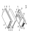
- FIG. 5 provides a perspective view, partly from the front, of a switch cartridge 50 .
- the term “front” is applied in the context of the position, when installed, of the switch cartridge 50 , with respect to the shelf 20 (i.e. in this case the “front” of the switch cartridge 50 is innermost part of the switch cartridge 50 when it is inserted in the shelf 20 ).
- a switch cartridge 5 is three-dimensional, having a height (H), width (W) and depth (D).
- the switch cartridge 50 has one dimension (hereinafter described as the width, W) smaller than the other dimensions (hereinafter described as the depth, D, and height, H).
- An enclosure 52 of present example of a switch cartridge 50 has six, generally rectangular, faces. For convenience only, the face that is visible from the rear of the racking when a switch cartridge 50 is mounted in the shelf 20 is known as the rear face 521 . The opposite face is known as the front face 522 .
- these two faces, as well as top and bottom faces 523 and 524 have the shape of elongate rectangles.
- the side faces 525 and 526 are also rectangular, but not elongate in the manner of the front, rear, top and bottom faces.
- the switch cartridges have six generally rectangular faces, as for the information processing cartridge 40 it will be appreciated that other examples could have other configurations.
- the switch cartridge enclosure 52 is fabricated from steel sheet to form a chassis portion that includes one side face 526 , the front and rear faces 542 and 541 and the top and bottom faces 523 and 524 .
- a cover portion is secured to the chassis portion forms the other side face 525 .
- the cover portion is secured to the chassis portion by suitable fixings, for example one or more screws 527 . It will be appreciated however, that in another example, the cover portion could be used to form another of the faces, with the chassis portion forming the remaining faces.
- the provision of the enclosure 52 means that the switch cartridge 50 can safely be handled by an operator who is not a skilled technician. Also, through the use of the enclosure 52 , the switch cartridge is a robust unit that protects its inner workings from the outside environment and vice versa.
- the use of a metal enclosure means that the switch cartridge includes its own electromagnetic shielding. To this end the switch enclosure 52 is provided with EMI fingers 51 to ensure metal contact with the shelf chassis and the adjacent components.
- the outer dimensions of the switch enclosure in the present example are 120 mm high, 44 mm wide and 303 mm deep.
- the switch cartridge 50 incorporates an injector handle 53 with an associated latch mechanism (not shown) on the rear face 521 for facilitating insertion and latching of the switch cartridge 50 within an aperture 25 in the shelf 20 .
- the front face 522 of the switch cartridge 50 is perforated 56 to allow for airflow into the switch cartridge 50 .
- the rear face 521 of the switch cartridge 50 is also perforated 53 to allow for air to be exhausted from the rear of the switch cartridge 50 .
- At least one fan located behind the perforated portion 56 of the front face is provided in a switch cartridge 50 to channel cooling air through the switch cartridge 50 from the front to the rear.
- LED indicators 54 can be provided on the rear face 521 of the switch enclosure 52 to indicate whether power is on, whether service intervention is required and whether the switch can be removed.
- Additional link status indicators are integral to 2 ⁇ 4 stacked RJ-45 connectors 55 .
- Electrical connections 57 are provided at the front face of the switch (i.e. on the face that in use is inside the shelf enclosure 22 ). Signal connections are provided through a 5-row, 2 mm pitch right angle female connector and power connections are provided through a 3-pin right angle connector.
- the connector arrangement includes a guide pin arrangement to prevent module misalignment during insertion of the switch cartridge module into the receiving location.
- Up to two switches 50 can be mounted at any one time at the rear of the shelf unit in corresponding aperture 25 in the rear wall of the shelf enclosure 22 .
- the number of switches 50 provided in any particular implementation depends upon system configuration and the need, or otherwise, for redundancy.
- FIG. 6 provides a perspective view, partly from the front, of an SSP cartridge 60 .
- the term “front” is applied in the context of the position, when installed, of the SSP cartridge 60 , with respect to the shelf 20 (i.e. in this case the “front” of the SSP cartridge 60 is innermost part of the SSP cartridge 60 when it is inserted in the shelf 20 ).
- SSP cartridge 60 is three-dimensional, having a height (H), width (W) and depth (D).
- the SSP cartridge 60 has one dimension (hereinafter described as the width, W) smaller than the other dimensions (hereinafter described as the depth, D, and height, H).
- An enclosure 62 of present example of an SSP cartridge 60 has six, generally rectangular, faces. For convenience only, the face that is visible from the rear of the racking when the SSP cartridge 60 is mounted in the shelf 20 is known as the rear face 621 . The opposite face is known as the front face 622 .
- these two faces, as well as top and bottom faces 623 and 624 have the shape of elongate rectangles.
- the side faces 625 and 626 are also rectangular, but not elongate in the manner of the front, rear, top and bottom faces.
- the SSP cartridges have six generally rectangular faces, as for the information processing cartridges 40 it will be appreciated that other examples could have other configurations.
- the SSP cartridge enclosure 62 is fabricated from steel sheet to form a housing portion that includes one side face 626 , the front and rear faces 642 and 641 and the top and bottom faces 623 and 624 .
- a cover portion that is secured to the housing portion forms other side face 625 .
- the cover portion is secured to the chassis portion by suitable fixings, for example one or more screws 627 . It will be appreciated however, that in another example, the cover portion could be used to form another of the faces, with the housing portion forming the remaining faces.
- the provision of the enclosure 62 means that the SSP cartridge 60 can safely be handled by an operator who is not a skilled technician.
- the SSP cartridge is a robust unit that protects its inner workings from the outside environment and vice versa.
- the use of a metal enclosure means that the SSP cartridge includes its own electromagnetic shielding.
- the SSP enclosure 62 is provided with EMI fingers 61 to ensure metal contact with the shelf chassis and the adjacent components.
- the SSP cartridge 60 incorporates an injector handle 63 with an associated latch mechanism (not shown) on the rear face 621 for facilitating insertion and latching of the SSP cartridge 60 within an aperture 26 in the shelf 20 .
- the front face 622 of the SSP cartridge 60 is perforated 66 to allow for airflow into the SSP cartridge 60 .
- the rear face 621 of the SSP cartridge 60 is also perforated 63 to allow for air to be exhausted from the rear of the SSP cartridge 60 .
- At least one fan located behind the perforated portion 66 of the front face) is provided in an SSP cartridge 60 to channel cooling air through the SSP cartridge 60 from the front to the rear.
- LED indicators 64 can be provided on the rear face 621 of the SSP enclosure 62 to indicate whether power is on, whether service intervention is required and whether the SSP can be removed.
- Electrical connections 67 are provided at the front face of the SSP (i.e. on the face that in use is inside the shelf enclosure 22 ). Signal connections are provided through a 5-row, 2 mm pitch right angle female connector and power connections are provided through a 3-pin right angle connector.
- the connector arrangement includes a guide pin arrangement to prevent module misalignment during insertion of the SSP cartridge module into the receiving location.
- FIG. 7 provides a perspective view, partly from the front, of a power supply unit (PSU) cartridge 70 .
- PSU power supply unit
- front is applied in the context of the position, when installed, of the PSU cartridge 70 , with respect to the shelf 20 (i.e. in this case the “front” of the PSU cartridge 70 is innermost part of the PSU cartridge 70 when it is inserted in the shelf 20 ).
- PSU cartridge 70 is three-dimensional having a height (H), width (W) and depth (D).
- the PSU cartridge 70 has two dimensions (hereinafter described as the width, W, and the height, H) that are generally similar.
- An enclosure 72 of present example of a PSU cartridge 70 has six, generally rectangular, faces. For convenience only, the face that is visible from the rear of the racking when the PSU cartridge 70 is mounted in the shelf 20 is known as the rear face 721 . The opposite face is known as the front face 722 .
- these two faces are at least approximately square, give that the width and height of the PSU cartridge are similar, whereas the other faces, although still rectangular, are not, in this example, square.
- the information processing cartridges 40 it will be appreciated that other examples could have other configurations.
- the PSU cartridge enclosure 72 is fabricated from steel sheet to form a housing portion that includes the bottom face 724 , the side faces 725 and 726 and the front and rear faces 742 and 741 .
- a cover portion that is secured to the housing portion forms the top face 723 .
- the cover portion is secured to the chassis portion by suitable fixings, for example one or more screws 727 . It will be appreciated however, that in another example, the cover portion could be used to form another of the faces, with the housing portion forming the remaining faces.
- the provision of the enclosure 72 means that the PSU cartridge 70 can safely be handled by an operator who is not a skilled technician.
- the PSU cartridge 70 is a robust unit that protects its inner workings from the outside environment and vice versa.
- the use of a metal enclosure means that the PSU cartridge includes its own electromagnetic shielding.
- the PSU enclosure 72 is provided with EMI fingers 71 to ensure metal contact with the shelf chassis and the adjacent components.
- the PSU cartridge 70 incorporates an injector handle 73 with an associated latch mechanism (not shown) on the rear face 721 for facilitating insertion and latching of the PSU cartridge 70 within an aperture 27 in the shelf 20 .
- the front face 722 of the PSU cartridge 70 is perforated 76 to allow for airflow into the PSU cartridge 70 .
- the rear face 721 of the PSU cartridge 70 is also perforated 73 to allow for air to be exhausted from the rear of the PSU cartridge 70 .
- At least one fan located behind the perforated portion 76 of the front face) is provided in a PSU a cartridge 70 to channel cooling air through the PSU cartridge from the front to the rear.
- LEd indicators 74 can be provided on the rear face 721 of the PSU enclosure 72 to indicate whether input power is good, whether output power is good, whether service intervention is required and whether the PSU can be removed.
- Electrical connections 77 are provided at the front face of the PSU (i.e. on the face that in use is inside the shelf enclosure 22 ) for connection to the shelf.
- the PSU 70 connects to the shelf through a 5P/24S/6P configuration SSI-MPS compliant right angle connector at the front face 722 of the PSU 70 .
- a power inlet 71 for each PSU 70 incorporates a cable/connector retention mechanism on the rear face 721 of the PSU to prevent accidental or malicious removal of the power input cord from the PSU 70 .
- the shelf unit enclosure provides slots at the rear of the shelf unit for two hot-swappable, AC input PSUs 70 .
- both PSU slots are populated.
- blanking panels/modules are fitted to all unpopulated positions to maintain the correct airflow and thermal characteristics of the shelf, a safe internal operating temperature for the shelf life expectancy of all shelf components, electromagnetic compliance (EMC) containment and electrostatic discharge (ESD) containment.
- EMC electromagnetic compliance
- ESD electrostatic discharge
- each of the FRUs such as the information processing cartridges 40 , is contained in its own robust enclosure to facilitate EMC, ESD, handling, storage and transportation.
- Each FRU is configured as a ‘sealed’ unit with no field or customer serviceable parts internally.
- the FRUs are configured to plug into the enclosure and to be hot swappable.
- the FRUs are keyed to prevent incorrect positioning and insertion into the enclosure and are arranged positively to be retained in the shelf by a latching/locking mechanism.
- the FRUs described above are not provided with removable media. Internal data storage is provided by 2.5′′ IDE 9.5 mm or 12.7 mm profile hard disk drive (HDD) devices (complying to SFF-8201) mounted internally in each information processing cartridge 40 and in the SSP cartridge 60 .
- the drives are not considered as FRUs, and are not hot-swappable disk drives in the present example.
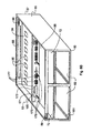
- FIG. 8A is a schematic plan view showing the internal configuration of the shelf 20 with the cover 226 removed.
- FIG. 8B is a schematic perspective view from the rear of the chassis portion 21 of the shelf enclosure with the field replaceable units also removed.
- a vertically mounted midplane 80 extends across the shelf 20 and allows for the electrical interconnection of the FRUs.
- the various apertures in the front and rear walls 221 and 222 of the shelf 20 in combination with the midplane 80 , provide guides (e.g., rails 88 ) and keying e.g., offset connector positioning for the insertion of the FRUs into the enclosure and midplane 80 .
- the midplane 80 is a double-sided printed circuit board (PCB) assembly that is mounted vertically in a rigid manner within the enclosure. It carries connectors 84 on a front surface 81 for making electrical connection with corresponding connectors 47 on the information processing cartridges 40 .
- PCB printed circuit board
- the midplane 80 provides connectors for receiving corresponding connectors connected to first and second indicator boards 88 and 89 that each carry a respective set of LED indicators 36 .
- the midplane 80 is not regarded as a FRU on its own and is not hot swappable. It is perforated to facilitate airflow through the shelf 20 .
- the midplane 80 includes openings 89 , that cooperate with openings in the enclosures of the FRUs 40 , 50 , 60 and 70 , to provide a path for cooling air to pass from the front to the rear of the shelf 20 , the cooling air being forced through by fans in the respective FRUs 40 , 50 , 60 and 70 .
- the midplane 80 connects all the elements of a shelf together, including, in the present example, up to sixteen information processing cartridges 40 , up to two switches 50 , an SSP 60 , two PSUs 70 and the two indicator boards 88 and 89 .
- the midplane 80 is only element of a shelf (other than the chassis) that is not hot swappable. Accordingly, to maximize the system reliability, the midplane is configured to provide as a high level of reliability as possible. To this end, the midplane is configured not to include active devices and to include the minimum number of decoupling capacitors consistent with good design practice (ideally zero).
- the midplane supports a number of paths (e.g., 83 ) for various power and signal lines to interconnect the FRUs. It will be appreciated that the signal paths 83 shown in FIG. 8B are merely schematic and that many more such paths are required on or within one or more layers of the midplane 80 .
- each information processing cartridge 40 has a high speed information signal connection (e.g., a Gbit Ethernet SERialiser/DESerialiser (SERDES) connection) to each of the switches 50 , each connection consisting of two pairs of differential signals.
- SERDES Gbit Ethernet SERialiser/DESerialiser
- each information processing cartridge 40 and switch 50 has a serial console connection to the SSP 60 .
- Each connection consists of two TTL level signals that make a transmit and return (TX and RX) pair.
- each PSU 70 and switch 50 has a management signal connection (e.g., a serial I2C connection) to the SSP 60 to control power and monitor environmental parameters.
- the I2C bus consists of two signals SCL and SDA.
- an I2C address programming pin is provided for the PSUs 70 and switches 50 .
- Identification information (FRU ID) for the midplane 80 is held on an I2C electrically erasable programmable read only memory (EEPROM) 90 in the front indicator board 88 .
- the SSP 60 provides a current limited supply to the indicator boards 88 and 89 via the midplane.
- the indicator boards 88 and 89 is also provided with an I2C address programming pin.
- a FRU ID EEPROM 90 may also be available on the rear indicator board 89 .
- Each information processing cartridge 40 , switch 50 and PSU 70 signals to the SSP 60 that it is inserted by pulling to GND a respective inserted_signal. These signals are fed to the SSP 60 via the midplane 80 .
- Each PSU 70 has five 12 Volt output rails. The routing from each PSU 70 is arranged so that a fault in any single FRU cannot completely interrupt the power to any other.
- the midplane 80 is provided with appropriate connector arrangements for receiving the connectors on the FRUs.
- the information processing cartridge 40 connects to the midplane 80 through a 40 pin SCA-2 connector. Accordingly, the midplane cares corresponding connectors 84 .
- Each switch 50 connects to the midplane 80 through a right-angle 40 pair connector.
- the corresponding connectors 85 on the midplane are straight male parts with a power connector.
- a guide pin arrangement is provided in addition to the connectors to prevent misaligned modules causing bent pins during insertion.
- a power module is used to provide connection between the power rails. The center pin is longer on the switch modules to provide a leading ground.
- the SSP 60 connects to the midplane 80 through a right-angled 125 way 5 row 2 mm connector.
- the connector 86 on the midplane 80 is a straight male part.
- a guide pin arrangement is provided in addition to the connectors to prevent misaligned modules causing bent pins during insertion.
- the same power connectors as used on the switch interconnection may be used, or alternatively spare pins on the 2 mm connector may be used for the 12V power.
- Each PSU 70 connects to the midplane 80 through an SSI “MPS” specification connector.
- the contacts are configured 5P/24S/6P with sequenced signal and power “pins”.
- the mating connector 87 on the midplane can be a 1450540-2 vertical receptacle, press-fit connector.
- the indicator boards 88 and 89 are identical at the front and rear of the system and are configured as FRUs. They hold three system-level indicator LEDs 36 and a FRU-ID PROM 90 each. Three LEDs 36 are present on the indicator board. There is a white locator LED that can be switched by the user for locating the system; a green power-on LED to indicate when the system is powered; and a red service-required LED to indicate a fault or other condition requiring servicing. They are all driven by the SSP 60 .
- the FRU-ID for the midplane 80 is held on the indicator boards 88 and 89 , so that the midplane can be a totally passive unit.
- the front and rear indicator boards are identical, one FRU-ID PROM is available on each board.
- the FRU-ID PROMs communicate with the System Service processor (SSP) via an I2C bus.
- SSP System Service processor
- Each device on the bus has a separate I2C address.
- the lower three I2C address bits of the EEPROMs used are available as pins on the device, to allow programming with resistors.
- the least significant bit of this address (A0) is passed to the midplane via the corresponding connector.
- the midplane 80 allows the midplane 80 to program the address of the FRU-ID differently for the front and rear indicator boards 88 and 89 , by pulling the address low for the front board and high for the rear indicator board 89 . This ensures that both EEPROMS are available on the bus, at different addresses.
- the FRU-ID for the midplane can be stored on either front or rear EEPROMS 90 , but the SSP 60 is configured to use the EEPROM 90 on the front indicator board 88 .
- the EEPROM is at least 8 kByte in size.
- the path of the airflow from the front of the shelf to the back of the shelf can be configured to be as efficient as possible, depending on the detail configuration of the fan units and the ventilation openings or apertures in the information processing, switch, service processor and power supply unit modules 40 , 50 , 60 and 70 .
- Providing the fan units in the field replaceable units 40 , 50 , 60 and 70 contributes to the aim of maintaining the chassis 21 and the midplane 80 of the shelf 20 free of active components, thereby minimising cost, and facilitating maintenance.
- by providing the fan units in each of the field replaceable units merely inserting and removing field replaceable units automatically adapts the flow of cooling air to the number and type of field replaceable units inserted in the shelf 20 .
- the information processing cartridge 40 includes a microprocessor 412 (in the present example an UltraSPARC processor).
- the microprocessor is mounted on an information processing cartridge motherboard 410 .
- a configurable clock generator 414 is implemented as a programmable clock synthesizer employing a crystal is used to produce CPU clock signals, CLKA and CLKB. The clock frequency is determined by jumper settings (not shown).
- a vectored interrupt controller (I-Chip) 416 and a configurable core voltage regulator module (VRM) 418 are provided.
- Two sockets on a riser card from the information processing cartridge motherboard 410 are provided for buffered PC 133 dual in line memory modules (DIMMs) 430 with a 72-bit data path with error correction codes (ECC).
- the memory capacity can be chosen to suit the processor addressable memory space. For example, up to 4 GB of addressable memory can be provided.
- Serial Presence Detect (SPD) auto-configuration is provided via an SMBus over an I2C bus 432 .
- a PCI bus architecture is employed with a so-called SouthBridge bus bridge 436 with SuperIO and two Gb Ethernet MAC devices.
- a 32bit PCI bus 434 is provided from the microprocessor 412 .
- other bus protocols e.g., Infiniband
- the SouthBridge 436 is a standard form of bus bridge packaged in a 352 pin PBGA package that provides the following functions:
- two AC-coupled Ethernet interfaces 450 and 452 are provided, these are packaged in a 316 pin PBGA. These Ethernet interface are operable to provide a PCI attached Ethernet MAC with PCS functionality, capable of operation up to Gigabit Ethernet performance.
- the physical layer is implemented using SERialiser/DESerialisers (SERDESs) 454 and 456 .
- SERDESs SERialiser/DESerialisers
- the SERDES uses differential PECL TX+/ ⁇ and RX+/ ⁇ pairs to communicate over the midplane 80 .
- the RX+/ ⁇ pairs are AC coupled the information processing cartridge 40
- the TX+/ ⁇ pairs are AC coupled at each switch 50 . This facilitates hot-swap of the information processing cartridges 40 and the switch(es) 50 .
- An asynchronous serial connection 457 for communication between the BSC 442 and the SSP 60 is provided.
- Internal data storage is provided by an UltraDMA100 ATA hard disk 446 with a capacity of 30 GB or more rated for 24/7 continuous operation.
- the hard disk 446 is accessed using the primary IDE interface of the SouthBridge 436 .
- the hard disk 446 can hold an operation system, for example a Solaris operating system, and other software and data for performing information processing using the main, or host, processor (CPU) within the information processing module 40 .
- the BSC 442 is implemented as a microcontroller, specifically a Hitachi H8S/2148 microcontroller, part number HD64F2148AFA20.
- the BSC 442 provides various functions, including:
- the BSC 442 is powered by a 5V service bus (SB) rail as soon as the SSP 50 is fully inserted into the midplane 80 , it then turns on the rest of the DC/DC converters to provide power to the remainder of the information processing cartridge.
- a BSC reset signal is derived from a simple conventional power on reset (POR) generator that monitors the 5VSB rail.
- a 1 MByte Flash PROM 446 is provided.
- a 16 kByte I2C EEPROM 458 that is accessible via the BSC 442 contains BSC variables and boot variables.
- the EEPROM is nominally divided into 8 kB for the boot variables and 8 kB for the BSC variables.
- Write protection is implemented by BSC firmware.
- FRU-ID variables arm stored in a second 16 kByte I2C EEPROM 460 , accessible via the SouthBridge SM Bus port over the Xbus 437 .
- the EEPROM 460 contains 16 kB for FRU-ID of which the upper 2 kBytes is write protected.
- the write protection is also implemented by the BSC firmware.
- An environmental monitor sensor 466 monitors the CPU and ambient temperatures. This sensor is accessible via the onboard I2C bus from the BSC.
- a 5V DC/DC converter is turned on as soon as the FRU is fully inserted, but only the BSC 442 and required portions of the SouthBridge 436 are powered (the 5VSB rail).
- a FET is used to gate off the main 5V supply to the rest of the information processing cartridge 40 .
- the DC/DC converter outputs and the main 5V FeT do not turn on until the BSC 442 turns them on via a signal from the SouthBridge 436 .
- the SouthBridge 436 is used so that if the BSC 442 is reset (by a watchdog timeout or after a firmware download) the state of the DC/DC converters is not affected. When the remaining outputs from the converters 472 are within specifications a PWR_GOOD signal is asserted low to the BSC 442 .
- a SouthBridge resume circuit runs from 3V3 so a simple Zener diode dropper circuit is used to generate 3V3 from the 5VSB supply.
- a soft start controller which controls a ramping-up of voltage levels, is enabled when the INSERTED_L signal is asserted low, this signal is on a short pin in the connector and is connected to GND through the midplane 80 .
- the processor fan 462 runs at full speed to minimize the temperature of the information processing cartridge 40 and the fan.
- the speed of the processor fan and sink is monitored by the BSC 442 , using a tachometer sense pin on the H8 microcontroller. In the event of the fan speed falling below 80% of its nominal speed, the BSC 442 can be arranged to issue an alert.
- the nominal speed of the fan is recorded as part of the BSC EEPROM contents.
- the midplane connector 47 for the information processing cartridge 40 establishes the connection between the switch FRU and the midplane. It supports up to 84 connections (pins) that will deliver SERDES outputs 492 , 494 , I2C signals 496 , and power 498 , 499 . Signal connections may be made through a right-angled connector. Power connections are made through a 3 information processing cartridge right-angled connector.
- the connector is configured to facilitate hotswapping of the information processing cartridge with a low insertion force.
- the connector also uses guide pins to increase the ease of serviceability and prevent module misalignment during insertion.
- FIG. 10A provides an overview of the functional components of the switch 50 .
- FIG. 10B illustrates which of those components are provided on a switch component board
- FIG. 10C illustrates which of those components are provided on a processor component board.
- the midplane connector 57 on the switch 50 establishes the connection between the switch 50 and the midplane. It supports up to 84 connections (pins) that will deliver SERDES outputs 591 - 594 , I2C signals 596 , and power 598 , 599 . Signal connections may be made through a 40-pair right-angled connector. Power connections are made through a 3 information processing cartridge right-angled connector.
- the connector is configured to facilitate hotswapping of the board with a low insertion force.
- the connector also uses guide pins to increase the ease of serviceability and prevent module misalignment during insertion.
- An interboard connector pair 550 , 551 within the switch enclosure establishes a connection between the switch component board 501 and the microprocessor component board 502 . It supports connections (pins) for I2C signals, PCI bus bridging, 10/100 Ethernet PHY output, and power to the DC/DC converters.
- the switch component board 501 carries the switching components and interfaces and the processor component board 502 carries all other components, including the CPU, DRAM DIMM and I2C components.
- a PCI bus 534 is used to bridge the boards together. All signals from the processor component board 502 are routed through the inter-board connector to the switch component board.
- the switch component board 501 then provides connections to the midplane 80 through the midplane connector 57 .
- a switch microprocessor 512 is, in the present example (a Power PC (MPC8245)), packaged in a 352 pin Tape Ball Grid Array (TBGA) package, This microprocessor 512 supports between 1 MB to 2 GB of address space in the present example. It further includes an Embedded Programmable Interrupt Controller (EPIC) that provides 5 hardware interrupts (IRQs) or 16 aerial interrupts. There are 4 programmable timers with cascade mode function.
- EPIC Embedded Programmable Interrupt Controller
- a 32 bit PCI bus 534 operates at 33 MHz/66 MHz.
- a four-pin UART or dual two pin UARTs (DUART) are used as test/debug port (3 pin RS232).
- a commodity PC133 ECC DIMM 430 is provided with a 64 bit+8 bit data pat with ECC.
- Each ASIC provides twelve GMII Interfaces (1 Gigabit Ethernet) and one 10 Gb XGMII interface.
- the XGMII interface (10 Gb) is used to allow chip-to-chip communication (bridging) 542 between the ASICs 540 and 541 .
- Eight 1 Gb ‘uplinks’ will be provided for external communication through two quad PHYs 547 and 548 and RJ45 connectors on the rear panel.
- the ASICs 540 and 541 are configured through its PCI interface (32 bit/33 MHz) to the PCI bus 534 .
- a Flash PROM 552 stores a real time operating system, and management and configuration data for the microprocessor.
- the Flash PROM 552 is operable to hold 8 MB-16 MB of data, depending on the software required.
- the flash PROM 552 is operated via an on-chip Xbus 553 .
- An 8 kByte I2C EEPROM 554 is used to store the FRU-ID and is accessible by the SSP 60 .
- the upper 2 kByte of the EEPROM 554 is write protected.
- An 8-bit general purpose IO expansion chip 555 is provided for an I2C bus 556 .
- a system hardware monitor 557 performs management functions including monitoring all the voltage rails from DC/DC converters 559 to ensure that they are within limits specified in its limit registers, with watchdog comparisons of all DC/DC converter outputs being made.
- the system hardware monitor 557 also has tachometer inputs that are connected to tachometer outputs of the switch fan 560 to detect fan failures. A fan failure is reported through the I2C bus 556 .
- the midplane connector 59 includes the sixteen 1 Gigabit Ethernet connections 591 - 594 from the four quad SERDES 543 - 546 , one 100 BASE-T connection to the SSP 595 , and the I2C bus lines 596 .
- the SSP 60 has access to the I2C devices (FRU-ID EEPROM, 8-bit I/O expansion chip, and the system hardware monitor) through the midplane 80 .
- I2C devices FRU-ID EEPROM, 8-bit I/O expansion chip, and the system hardware monitor
- rear panel Gigabit Ethernet connections are provided from the two quad PHYs 540 , 541 to 2 ⁇ 4 stacked RJ45 connectors (8 uplinks). Each port is an independent 10/100/1000 BASE-T (auto negotiating) port.
- the PHY devices 540 , 541 operate in GMII mode to receive signals from the 8-Gigabit interfaces on the ASICs 530 , 532 .
- An integrated MAC/PHY device 561 provides its own interface to the PCI bus 534 .
- This MAC/PHY device 561 provides a management interface to the SSP 60 .
- the connection from the integrated MAC/PHY device 561 to the SSP 60 is coupled capacitively.
- a loopback mode is provided by the MAC/PHY device 561 for system diagnostics.
- An I2C regulator 562 is powered as soon as the switch is fully inserted into the midplane. This is facilitated through short pins connected to a soft start controller 563 , which controls a ramping-up of voltage levels. SSP software turns on the other DC/DC regulators through the 8 bit IO expander 555 .
- dual 12V input secondary converters 559 are provided with the soft start controller 563 to facilitate hot-insertion.
- the DC/DC converters 559 are individually fused 564 , 565 and then diode commoned 566 , 567 .
- a 5V DC/DC converter (I2C power regulator) is turned on as soon as the switch 20 is fully inserted.
- a 3.3V DC/DC converter is not turned on until the 8 bit IO expander 555 turns them on through SSP service software (ON_L is asserted low).
- the 3.3V converter turns on the 2.5V, 1.2V, and V core converter when the voltage are within an appropriate range. All power rails are monitored by the hardware system monitor 557 .
- the outputs of the DC/DC converters 559 are fed in to the A/D inputs of the hardware system monitor 557 and Watchdog comparisons will be made to the volt age limits set in the limit registers.
- a soft start controller which controls a ramping-up of voltage levels, is enabled when an INSERTED_L signal is asserted low, this signal being on a short pin in the connector and being connected to GND through the midplane until one of the supplies is removed.
- These circuits are configured to withstand an overvoltage at their inputs whilst the input they are feeding is not powered, without any leakage to the unpowered circuit.
- a sense circuit detects if the voltage has dropped below 2.0V (from either a blown fuse or a power rail going down). The DC/DC converters 559 are protected against short circuit of their outputs so that no damage occurs.
- a fan 560 provides cooling.
- the fan 560 runs at full speed to prevent overtemperature conditions by minimizing the temperature of the internal components and the fan.
- the speed of the fan 560 is monitored by the SSP 60 through the system hardware monitor 557 on the switch 50 .
- the system hardware monitor 557 is alerted in the event of the fan speed falling below 80% of its nominal speed.
- the fan provides tachometer outputs to facilitate the measurement of fan speed.
- LED indicators 568 are provided, with a green power LED, an amber LED for indicating that service is required and a blue LED for indicating that the switch is ready to be removed. LED indicates integrated on 2 ⁇ 4 stacked RJ45 connectors on the front panel show green when the link is present and flash green when the link is active.
- the SPP 60 includes a microprocessor 612 (in the present example an UltraSPARC processor).
- the microprocessor is mounted on an information processing cartridge motherboard 610 .
- a configurable clock generator 614 is implemented as a programmable clock synthesizer employing a crystal used to produce CPU clock signals, CLKA and CLKB. The clock frequency is determined by jumper settings (not shown).
- a vectored interrupt controller (I-Chip) 616 and a configurable core voltage regulator module (VRM) 618 are provided.
- the SPP 60 supports one commodity buffered PC133 dual in line memory module (DIMM) 630 with a 72-bit data path with error correction codes (ECC).
- the memory capacity can be chosen to suit the processor addressable memory space. In the present example, up to 1 GB of addressable memory can be provided.
- Serial Presence Detect (SPD) auto-configuration is provided via an SMBus over an I2C bus 632 .
- a PCI bus architecture is employed with a so-called SouthBridge bus bridge 636 with SuperIO.
- the SouthBridge 636 is a standard form of bus bridge packaged in a 352 pin PBGA package that provides the following functions:
- An Ethernet MAC/PHY device 650 provides a connection to an embedded switch device 651 on the SSP 60 . This connection can be capacitively coupled.
- the embedded switch 650 provides a connection from the external management network to the SSP 60 and switches 50 and also from the SSP 60 to the switches 50 .
- the embedded switch 650 is controlled by an H8 microcontroller 656 via an SPI interface. Although the switch 650 is unmanaged and is intended to be isolated from the rest of the SSP 60 , the H8 microcontroller to employed to implement a control protocol.
- the embedded switch 650 and its H8 microcontroller 656 are powered from a 5VSB rail.
- Octal UARTS 652 and 653 are connected between the PCX bus 634 and the midplane connector 67 .
- a real time clock RTC 654 with a back-up battery is provided.
- a flash PROM 655 is also provided. These are accessible via the Xbus 636 .
- the hard disk 646 is accessed using the Primary IDE interface 644 of the SouthBridge.
- the disk can be the same as the disk used in the information processing cartridges.
- the hard disk 646 can hold an operating system, for example a Solaris operating system, and other software and data for performing management signal processing using the main, or host, processor (CPU) within the SSP module 60 .
- an operating system for example a Solaris operating system, and other software and data for performing management signal processing using the main, or host, processor (CPU) within the SSP module 60 .
- the SSP can be provided with a field replaceable memory card 657 to hold network identities (e.g. Media Access Control (MAC) addresses for the shelf and for the 16 blades, as well as other information that may need to be transferable between a failed SSP 60 and its replacement.
- network identities e.g. Media Access Control (MAC) addresses for the shelf and for the 16 blades, as well as other information that may need to be transferable between a failed SSP 60 and its replacement.
- the memory card data is accessible over an I2C bus 658 via the SSC 642 . To remove the memory card 657 from the SSP 60 , the SSP 60 must first be removed from the Shelf.
- An 16 kByt I2C EEPROM 659 is accessible via the SSC microcontroller 642 .
- the EEPROM 659 contains SSC and boot variables.
- the EEPROM 656 is nominally divided into 8 kB for the boot variables, and 8 kB for the BSC variables.
- Write protection is implemented by SSC firmware, typically by acknowledging the writes but not carrying them out.
- FRU-ID variables for the SSP 60 are stored in a second 16 kByte I2C EEPROM 655 , accessible via the SouthBridge SM Bus port over the Xbus 636 .
- the EEPROM 655 contains 16 kB or FRU-ID of which the upper 2 kBytes is write protected.
- the write protection is also implemented by the SSC firmware by acknowledging the writes but not carrying them out.
- a temperature monitor 670 monitors the CPU and ambient temperature.
- the temperature monitor 670 is accessible via the onboard I2C bus from the SSC 642 .
- a first serial port (SER A) 675 is provided from the SSC 642 .
- a second serial port (SER B) 648 is provided from a COM2 port on the Southbridge 636 .
- the serial ports use RS232 compatible signalling levels and are available at RJ45 connectors 671 on the rear face of the SSP enclosure 62 .
- a USB port 0 from the SouthBridge 636 is also made available at a connector 672 on the rear face of the SSP enclosure 62 .
- the SSC 642 is implemented by a microcontroller, specifically a Hitachi H8S/2148 microcontroller, part number HD64F2148AFA20.
- the SSC provides a number of system management functions, including:
- the SSC 642 is configured such that it is powered as soon as the SSP 60 is fully inserted into the midplane 80 .
- the SSC 642 is then operable to turn on the rest of the DC/DC converters 674 to provide power to the remainder of the SSP 60 .
- An SSC reset signal is derived from a simple power-on-reset (POR) generator that monitors the 5VSB rail.
- the inrush current is limited to ⁇ 1 A and the rate of rise is configured not to exceed 20 A/s to provide a so-called soft start to facilitate hot-insertion.
- the intent is to prevent damage to the connectors and to avoid generating noise.
- a soft start controller which controls a ramping-up of voltage levels, is enabled when the INSERTED_L signal is asserted low, this signal is on a short pin in the connector and is connected to GND through the midplane 80 .
- the CPU fan 676 is not speed controlled and runs at full speed. The intent is to minimise the temperature of the SSP 60 and the fan 676 .
- the speed of this fan is monitored by the SSC 642 using a tachometer sense pin on the H8 microcontroller. In the event of the fan speed falling below 80% of its nominal speed, the SSC 642 generates an alert. The nominal speed of the fan is recorded as part of the SSC EEPROM contents.
- the SSC controls the LED status indicators 64 on the SSP, including a green power LED, an amber LED for indicating that service is required and a blue LED for indicating that the SSP is ready to be removed. These indicators are driven by the SSC 642 by active low outputs and are powered from a 5VSB rail.
- the SSP also controls the shelf indicators at the front and rear of the system, including the white locator LED that can be switched by the user for locating the system; the green power-on LED to indicate when the system is powered; and the red service-required LED to indicate a fault or other condition requiring servicing. These indicators are driven by the SSC 642 using active high outputs, and both of the front and rear shelf indicators are powered from the 5VSB rail.
- the connector between the SSP 60 and the midplane 80 is provided by a 5-row, 2 mm pitch right angle female connector.
- a guide pin arrangement prevents misaligned modules during insertion causing bent pins.
- SSP midplane connections 67 interconnect the SSP 60 and the midplane 80 . They include connections (pins) for the OCTART circuits 652 , the I2C bus and power. Signal connections are provided through a 5-row, 2 mm pitch right angle female connector and power connections are provided through a 3-pin right angle connector.
- the connectors are configured to facilitate the hotswapping of the SSP cartridge with a low insertion force.
- the connector also uses guide pins to increase the ease of serviceability and prevent module misalignment during insertion.
- the PSUs 70 are configured such that when two or more PSUs 70 are connected in parallel in the shelf 20 , failure of any one of the paralleled units shall not affect system operation. Moreover, one of the PSUs can installed or removed from a “live” system with or without input power applied. All outputs have overcurrent protection.
- the PSU has an I2C interface to provide power supply status via the midplane 80 .
- the PSU has an internal temperature sensor that reports via the I2C interface.
- the PSU fan speed is also monitored and errors are reported via the I2C interface.
- Overvoltage and overcurrent sensors also report via the I2C interface.
- the power supply has four front panel LED indicators.
- a blue “Ready to Remove” LED is driven by the I2C interface and indicates that the power supply may be removed from the system.
- An amber “Service Required” LED is driven by the I2C interface and indicates that the power supply is in a fault condition: any output out of range, over-temperature or shutdown.
- a green “DC Output-OK” indicator is driven by internal power supply circuits and shows that the main 12 volt supply is functioning. The LEDs remain lighted when individual outputs are in the current limited mode of operation.
- a green “AC Input-OK” indicator is driven by internal power supply circuits and shows that AC input power is within normal operating range.
- the PSU 70 connects to the shelf through a 5P/24S/6P configuration SSI-MPS compliant right angle connector at the front face 722 of the PSU 70 .
- Connectors for the I2C interface are also provided.
- a power inlet 71 for each PSU 70 incorporates a cable/connector retention mechanism on the rear face 721 of the PSU to prevent accidental or malicious removal of the power input cord from the PSU.
- up to 16 information processing cartridges, or blades 40 are configured as sealed FRUs on a single shelf 20 , the number of blades being chosen according to customer requirements.
- Each blade has its own processor and random access memory. If, for example, there is a maximum of 2 Gbytes of memory per information processing cartridge, this provides for a maximum system of 16 processors (16P) with 5.33 processors per unit height (IU) and a total of 32 GB of memory per shelf.
- the shelf 20 incorporates a shelf service processor (SSP) module 60 , redundant switch modules 50 and redundant power supply units (PSUs) 70 separate from the blades 40 .
- SSP shelf service processor
- PSUs redundant power supply units
- the information processing cartridges can be kept compact and inexpensive. Also, as a result, they can be powered by DC power only, via the midplane 80 .
- the FRUs (that is the information processing cartridges, or blades, 40 , the switches 50 , the SSP 60 and the PSUs 70 ) are all configured as sealed units that do not contain any internal FRUs themselves and do not contain user serviceable items.
- the enclosures of the FRUs enclose all of the functional components of the FRU with only electrical connectors being externally accessible and with indicator LEDs being externally visible as well.
- a configuration as described provides an easily scalable processor architecture, whereby the processing power provided by a complete system based on the information processing cartridge/information processing cartridge carrier architecture can be scalable from moderate to very high capacity though the simple addition of further information processing cartridges.
- the external connections from a shelf 20 are in the form of two information signal connection (e.g., Ethernet connections) 122 and 124 , power connections 126 and a signal management connection 128 . It will be appreciated, therefore, that the connections to a shelf can be kept to a minimum. It will further be appreciated from the configuration shown in FIG. 12 that the system is scalable beyond a single shelf unit 20 .
- FIG. 13 illustrates how a plurality of shelves can be configured within one (or more) racks to provide even high processing power.
- a constellation of shelves to provide a large grouping of servers is sometimes termed a “web farm” 130 .
- the web fan comprises a plurality of shelves 20 that each carry a plurality of blades 40 .
- NAS network attached storage devices
- FIG. 13 illustrates how a plurality of shelves can be configured within one (or more) racks to provide even high processing power.
- the web fan comprises a plurality of shelves 20 that each carry a plurality of blades 40 .
- NAS network attached storage devices
- FIG. 14 illustrates one example of a high multi-server system 140 for implementing a network-connected web site such as, for example, an airline reservation system on the World Wide Web.
- an external network 142 e.g., the Internet
- gateways 146 which are connected to an entry edge server group 148 implemented by a web as shown in FIG. 13 .
- the entry edge server group 148 forms an interface to the external network 142 .
- the entry edge server group 148 is then connected by switches 150 and a firewall 152 to a web edge server group 154 that is also implemented as a web farm as shown in FIG. 13 .
- the web edge server group 154 serves to cache web pages that are readily accessible to users 144 accessing the system 140 from the external network 142 , for example for checking fight times, etc.
- the web edge server group 154 is further connected by a further firewall 156 to a plurality of application servers 158 , which are responsible for processing flight reservations.
- the application servers 158 are then connected via a further firewall 160 to computer systems 162 , 168 , for example, e-commerce services including financial services for receiving and processing payment for airline reservations.
- the system provides a shelf at is configured as an information processing cartridge carrier for carrying a selectable number of information processing cartridges.
- the information processing cartridges form a sealed, field replaceable unit containing at least one processor, memory, a storage device and a service controller.
- the information processing cartridge is configured with a minimum of external connections for data and service management information and for connection to a DC power source.
- the shelf also incorporates a Shelf Service Processor (SSP) module, dual redundant switch modules and dual redundant Power Supply Units (PSUs).
- SSP Shelf Service Processor
- PSUs Power Supply Unit
- Embedded storage is provided by a fixed non hot-swappable 2.5′′ hard disk drive in each of the information processing cartridges and in the SSP module.
- Built-in network functionality is provided through sixteen 10/100/1000BASE-T network ports, two asynchronous serial ports, two 10/100BASE-T management ports and one USB port.
- a rack mountable shelf that is configured to support a plurality of field replaceable units in the form of server cartridges that each include at least one server processor.
- the rack mountable shelf is configured to provide communal services for said server cartridges, including at last one of supplying DC operating power to the server cartridges, distributing information signals between the server cartridges and processing system management signals for the server cartridges.
- Each of the server cartridges can be slideably received in a respective one of a series of server cartridge receiving locations arrayed side by side along the front of the shelf.
- the server cartridges can be configured as thin blades to provide a high server density. For example, 16 server cartridge receiving locations can be provided across the front of the shelf.
- the supply of DC operating power to the server cartridges can be provided by one or more field replaceable power supply units (e.g. two redundantly configured power supply units) mounted in the shelf.
- the distribution of information signals between the server cartridges can be provided by one or more switch units (e.g. two redundantly configured switch units) mounted in the shelf.
- the processing of system management signals for the information processing cartridges is provided by one or more field replaceable service processor units (e.g. one service processor unit) mounted in the shelf.
- Each of the power supply, switch and service processor units can be slideably received in a respective receiving location at the rear of the shelf.
- a midplane including connectors with conductive paths therebetween can provide power, information signal and system management signal connections between received field replaceable units.
- a multiple computer server system can be formed from at least one rack mountable shelf as set out above.
- the information processing cartridge carrier supports a plurality of cartridges, it would also be possible to configure a standalone server or processor application having lower processing requirements.
- an information processing cartridge carrier could be configured as a base station with display and I/O interfaces for the connection of I/O devices (e.g., keyboards, background storage, network cards, etc.) and a display. Particularly if a limited number of one or more slots for receiving a respective information processing cartridge were provided in the base station, a computer for personal or business use at a work station could be provided.
Abstract
Description
-
- an SM Bus interface over the I2C bus 432 for access to the SPD (Serial Presence Detect) feature of the DIMMs that allows intialization of the memory controller;
- an Xbus interface for access via an
Xbus 437 to a EEPROM, a real time clock 440 and an information processing cartridge service controller (hereinafter termed a Blade Service Controller (BSC)) 442; - an IDE interface that provides an ATA-100 IDE connection 444 to an IDE disk drive 446; and
- a serial console interface on a service bus 448 to the BSC 442 that is used for operating system functions including a console function, this connection being provided without any buffering other than series resistors (not shown).
-
- dual access (for information processing cartridge and SSP) to EEPROMs 458, 460 for boot information and a FRU-ID for the information processing cartridge;
- channeling communication between an information processing cartridge 40 and the SSP 60;
- control of power on reset (POR), system reset and XIR to the
microprocessor 412; - control of the power, service-required and ready-to-remove LEDs 36;
- upgrading of field-upgradable firmware, via the serial interface;
- a watchdog function for the operating system;
- monitoring the speed of a CPU fen 462; and
- communications with a PROM 464 and the operating system via the Xbus 436.
-
- an SM Bus interface over the I2C bus 632 for access to the SPD (Serial Presence Detect) feature of the DIMMs that allows initialization of the memory controller;
- an Xbus interface for access via an Xbus 636 to a PROM, a real time clock 640 and a SSP service controller (hereinafter termed a SSP Service Controller (SSC)) 642;
- an IDE interface that provides an ATA-100 IDE connection 644 to an IDE disk drive 646; and
- serial console interfaces on a service bus 649 to the SSC 642 and 648 to a rear panel connector 680; and
- a USB connection to the rear panel connector.
-
- providing dual access via the Xbus 636 (for the information processing cartridges and the SSP) to the EEPROM 655 containing the boot and FRU-ID providing I2C access via the I2C bus 658 to the memory card 657 and via the I2C bus 673 to the EEPROM 659;
- providing I2access to the PSUs 70 and the
switches 50 via the midplane 80, with each PSU 70 and switch 50 having an individual I2C bus; - providing I2C access to the FRU-ID EEPROM for the midplane that is held on the
indicator boards 88 and/or 89; - controlling POR, System_Reset and XIR functions to the microprocessor 612;
- controlling power, service-required and ready-to-remove LEDs for the SSP 60;
- controlling power, service required and ready-to-remove LEDs for the shelf 20;
- controlling on/off functions of DC/DC converters 674 via the Southbridge;
- providing a common operating system/boot console and command port 675 via the rear panel (SER A);
- implementing a watchdog function for the operating system and boot functions;
- monitoring the speed of CPU and auxiliary fans 676 and 677; and
- monitoring the output voltage of the DC/DC converters 674.
Claims (12)
Priority Applications (6)
| Application Number | Priority Date | Filing Date | Title |
|---|---|---|---|
| US10/171,809 US7012815B2 (en) | 2001-08-10 | 2002-06-14 | Computer systems |
| JP2003519758A JP2005524884A (en) | 2001-08-10 | 2002-08-09 | Computer system |
| EP02758534.8A EP1466510B1 (en) | 2001-08-10 | 2002-08-09 | Server blade |
| PCT/GB2002/003666 WO2003014893A2 (en) | 2001-08-10 | 2002-08-09 | Server blade |
| AU2002324116A AU2002324116A1 (en) | 2001-08-10 | 2002-08-09 | Server blade |
| US10/828,460 US20040196727A1 (en) | 2001-08-10 | 2004-04-20 | Computer systems |
Applications Claiming Priority (3)
| Application Number | Priority Date | Filing Date | Title |
|---|---|---|---|
| US31150501P | 2001-08-10 | 2001-08-10 | |
| US36643002P | 2002-03-21 | 2002-03-21 | |
| US10/171,809 US7012815B2 (en) | 2001-08-10 | 2002-06-14 | Computer systems |
Related Child Applications (1)
| Application Number | Title | Priority Date | Filing Date |
|---|---|---|---|
| US10/828,460 Division US20040196727A1 (en) | 2001-08-10 | 2004-04-20 | Computer systems |
Publications (2)
| Publication Number | Publication Date |
|---|---|
| US20030030988A1 US20030030988A1 (en) | 2003-02-13 |
| US7012815B2 true US7012815B2 (en) | 2006-03-14 |
Family
ID=27390027
Family Applications (42)
| Application Number | Title | Priority Date | Filing Date |
|---|---|---|---|
| US10/143,537 Abandoned US20030033463A1 (en) | 2001-08-10 | 2002-05-10 | Computer system storage |
| US10/143,538 Active 2025-03-27 US7245632B2 (en) | 2001-08-10 | 2002-05-10 | External storage for modular computer systems |
| US10/172,723 Active 2024-07-18 US7062575B2 (en) | 2001-08-10 | 2002-06-14 | System and method for interfacing computer system information protocol interface modules |
| US10/171,817 Expired - Lifetime US6762934B2 (en) | 2001-08-10 | 2002-06-14 | Module ejection mechanism |
| US10/172,720 Expired - Lifetime US6778386B2 (en) | 2001-08-10 | 2002-06-14 | Cooling computer systems |
| US10/171,794 Abandoned US20030033360A1 (en) | 2001-08-10 | 2002-06-14 | Computer support module |
| US10/171,808 Active 2024-06-06 US7225235B2 (en) | 2001-08-10 | 2002-06-14 | Computer system console access |
| US10/171,908 Expired - Lifetime US6869314B2 (en) | 2001-08-10 | 2002-06-14 | Computer connections |
| US10/172,718 Active 2025-08-09 US7987223B2 (en) | 2001-08-10 | 2002-06-14 | Interfacing computer modules |
| US10/172,831 Expired - Lifetime US6912132B2 (en) | 2001-08-10 | 2002-06-14 | Support module ejection mechanism |
| US10/172,721 Abandoned US20030033365A1 (en) | 2001-08-10 | 2002-06-14 | Low cost computer system module interface |
| US10/172,829 Abandoned US20030030976A1 (en) | 2001-08-10 | 2002-06-14 | Cooling flow |
| US10/172,722 Active 2024-07-25 US7295442B2 (en) | 2001-08-10 | 2002-06-14 | System management |
| US10/171,811 Active 2028-05-02 US7765347B2 (en) | 2001-08-10 | 2002-06-14 | Console connection |
| US10/171,818 Active 2024-07-17 US7181543B2 (en) | 2001-08-10 | 2002-06-14 | Secure network identity distribution |
| US10/171,909 Active 2024-06-18 US7225239B2 (en) | 2001-08-10 | 2002-06-14 | Secure system unit mobility |
| US10/171,795 Expired - Lifetime US6924977B2 (en) | 2001-08-10 | 2002-06-14 | Computer system cooling |
| US10/171,898 Abandoned US20030033409A1 (en) | 2001-08-10 | 2002-06-14 | Secure network indentity allocation |
| US10/172,719 Expired - Lifetime US7013352B2 (en) | 2001-08-10 | 2002-06-14 | Interface standard support in modular computer systems |
| US10/171,855 Expired - Lifetime US6829141B2 (en) | 2001-08-10 | 2002-06-14 | Cooling power supplies |
| US10/171,810 Expired - Lifetime US6934150B2 (en) | 2001-08-10 | 2002-06-14 | Computer module housing |
| US10/171,809 Expired - Lifetime US7012815B2 (en) | 2001-08-10 | 2002-06-14 | Computer systems |
| US10/171,802 Active 2025-06-04 US7389535B2 (en) | 2001-08-10 | 2002-06-14 | Password management |
| US10/172,830 Expired - Lifetime US7174375B2 (en) | 2001-08-10 | 2002-06-14 | Modular computer system management |
| US10/171,822 Expired - Lifetime US7079395B2 (en) | 2001-08-10 | 2002-06-14 | Extended computing system |
| US10/215,668 Expired - Lifetime US6952659B2 (en) | 2001-08-10 | 2002-08-09 | Computer system monitoring |
| US10/215,666 Active 2024-12-14 US7299495B2 (en) | 2001-08-10 | 2002-08-09 | Virus detection |
| US10/215,652 Expired - Lifetime US7158781B2 (en) | 2001-08-10 | 2002-08-09 | System management |
| US10/215,651 Expired - Lifetime US7193844B2 (en) | 2001-08-10 | 2002-08-09 | Computer system storage |
| US10/215,662 Abandoned US20030051057A1 (en) | 2001-08-10 | 2002-08-09 | Edge protection |
| US10/215,648 Active 2024-07-21 US7224581B2 (en) | 2001-08-10 | 2002-08-09 | Extended computer systems |
| US10/215,653 Active 2024-12-13 US7225276B2 (en) | 2001-08-10 | 2002-08-09 | Configuring external network connections |
| US10/215,667 Expired - Lifetime US7032037B2 (en) | 2001-08-10 | 2002-08-09 | Server blade for performing load balancing functions |
| US10/215,669 Expired - Lifetime US6944019B2 (en) | 2001-08-10 | 2002-08-09 | Integrity monitoring |
| US10/215,649 Abandoned US20030051166A1 (en) | 2001-08-10 | 2002-08-09 | Privacy |
| US10/215,664 Expired - Lifetime US6980427B2 (en) | 2001-08-10 | 2002-08-09 | Removable media |
| US10/215,663 Abandoned US20030105859A1 (en) | 2001-08-10 | 2002-08-09 | Intrusion detection |
| US10/215,650 Abandoned US20030051167A1 (en) | 2001-08-10 | 2002-08-09 | Combined computer system |
| US10/828,460 Abandoned US20040196727A1 (en) | 2001-08-10 | 2004-04-20 | Computer systems |
| US10/839,684 Expired - Lifetime US7114994B2 (en) | 2001-08-10 | 2004-05-05 | Computer connections |
| US11/487,557 Expired - Lifetime US7289319B2 (en) | 2001-08-10 | 2006-07-14 | Extended computing system |
| US11/834,441 Abandoned US20080025292A1 (en) | 2001-08-10 | 2007-08-06 | Secure network identity allocation |
Family Applications Before (21)
| Application Number | Title | Priority Date | Filing Date |
|---|---|---|---|
| US10/143,537 Abandoned US20030033463A1 (en) | 2001-08-10 | 2002-05-10 | Computer system storage |
| US10/143,538 Active 2025-03-27 US7245632B2 (en) | 2001-08-10 | 2002-05-10 | External storage for modular computer systems |
| US10/172,723 Active 2024-07-18 US7062575B2 (en) | 2001-08-10 | 2002-06-14 | System and method for interfacing computer system information protocol interface modules |
| US10/171,817 Expired - Lifetime US6762934B2 (en) | 2001-08-10 | 2002-06-14 | Module ejection mechanism |
| US10/172,720 Expired - Lifetime US6778386B2 (en) | 2001-08-10 | 2002-06-14 | Cooling computer systems |
| US10/171,794 Abandoned US20030033360A1 (en) | 2001-08-10 | 2002-06-14 | Computer support module |
| US10/171,808 Active 2024-06-06 US7225235B2 (en) | 2001-08-10 | 2002-06-14 | Computer system console access |
| US10/171,908 Expired - Lifetime US6869314B2 (en) | 2001-08-10 | 2002-06-14 | Computer connections |
| US10/172,718 Active 2025-08-09 US7987223B2 (en) | 2001-08-10 | 2002-06-14 | Interfacing computer modules |
| US10/172,831 Expired - Lifetime US6912132B2 (en) | 2001-08-10 | 2002-06-14 | Support module ejection mechanism |
| US10/172,721 Abandoned US20030033365A1 (en) | 2001-08-10 | 2002-06-14 | Low cost computer system module interface |
| US10/172,829 Abandoned US20030030976A1 (en) | 2001-08-10 | 2002-06-14 | Cooling flow |
| US10/172,722 Active 2024-07-25 US7295442B2 (en) | 2001-08-10 | 2002-06-14 | System management |
| US10/171,811 Active 2028-05-02 US7765347B2 (en) | 2001-08-10 | 2002-06-14 | Console connection |
| US10/171,818 Active 2024-07-17 US7181543B2 (en) | 2001-08-10 | 2002-06-14 | Secure network identity distribution |
| US10/171,909 Active 2024-06-18 US7225239B2 (en) | 2001-08-10 | 2002-06-14 | Secure system unit mobility |
| US10/171,795 Expired - Lifetime US6924977B2 (en) | 2001-08-10 | 2002-06-14 | Computer system cooling |
| US10/171,898 Abandoned US20030033409A1 (en) | 2001-08-10 | 2002-06-14 | Secure network indentity allocation |
| US10/172,719 Expired - Lifetime US7013352B2 (en) | 2001-08-10 | 2002-06-14 | Interface standard support in modular computer systems |
| US10/171,855 Expired - Lifetime US6829141B2 (en) | 2001-08-10 | 2002-06-14 | Cooling power supplies |
| US10/171,810 Expired - Lifetime US6934150B2 (en) | 2001-08-10 | 2002-06-14 | Computer module housing |
Family Applications After (20)
| Application Number | Title | Priority Date | Filing Date |
|---|---|---|---|
| US10/171,802 Active 2025-06-04 US7389535B2 (en) | 2001-08-10 | 2002-06-14 | Password management |
| US10/172,830 Expired - Lifetime US7174375B2 (en) | 2001-08-10 | 2002-06-14 | Modular computer system management |
| US10/171,822 Expired - Lifetime US7079395B2 (en) | 2001-08-10 | 2002-06-14 | Extended computing system |
| US10/215,668 Expired - Lifetime US6952659B2 (en) | 2001-08-10 | 2002-08-09 | Computer system monitoring |
| US10/215,666 Active 2024-12-14 US7299495B2 (en) | 2001-08-10 | 2002-08-09 | Virus detection |
| US10/215,652 Expired - Lifetime US7158781B2 (en) | 2001-08-10 | 2002-08-09 | System management |
| US10/215,651 Expired - Lifetime US7193844B2 (en) | 2001-08-10 | 2002-08-09 | Computer system storage |
| US10/215,662 Abandoned US20030051057A1 (en) | 2001-08-10 | 2002-08-09 | Edge protection |
| US10/215,648 Active 2024-07-21 US7224581B2 (en) | 2001-08-10 | 2002-08-09 | Extended computer systems |
| US10/215,653 Active 2024-12-13 US7225276B2 (en) | 2001-08-10 | 2002-08-09 | Configuring external network connections |
| US10/215,667 Expired - Lifetime US7032037B2 (en) | 2001-08-10 | 2002-08-09 | Server blade for performing load balancing functions |
| US10/215,669 Expired - Lifetime US6944019B2 (en) | 2001-08-10 | 2002-08-09 | Integrity monitoring |
| US10/215,649 Abandoned US20030051166A1 (en) | 2001-08-10 | 2002-08-09 | Privacy |
| US10/215,664 Expired - Lifetime US6980427B2 (en) | 2001-08-10 | 2002-08-09 | Removable media |
| US10/215,663 Abandoned US20030105859A1 (en) | 2001-08-10 | 2002-08-09 | Intrusion detection |
| US10/215,650 Abandoned US20030051167A1 (en) | 2001-08-10 | 2002-08-09 | Combined computer system |
| US10/828,460 Abandoned US20040196727A1 (en) | 2001-08-10 | 2004-04-20 | Computer systems |
| US10/839,684 Expired - Lifetime US7114994B2 (en) | 2001-08-10 | 2004-05-05 | Computer connections |
| US11/487,557 Expired - Lifetime US7289319B2 (en) | 2001-08-10 | 2006-07-14 | Extended computing system |
| US11/834,441 Abandoned US20080025292A1 (en) | 2001-08-10 | 2007-08-06 | Secure network identity allocation |
Country Status (1)
| Country | Link |
|---|---|
| US (42) | US20030033463A1 (en) |
Cited By (26)
| Publication number | Priority date | Publication date | Assignee | Title |
|---|---|---|---|---|
| US20040196727A1 (en) * | 2001-08-10 | 2004-10-07 | Garnett Paul J. | Computer systems |
| US20040264112A1 (en) * | 2003-06-11 | 2004-12-30 | Koehler Loren M. | Intercoupling apparatus for server computer systems |
| US20050201053A1 (en) * | 2004-03-15 | 2005-09-15 | Xyratex Technology Limited | Data storage device carrier and chassis |
| US20050265385A1 (en) * | 2004-05-28 | 2005-12-01 | International Business Machines Corp. | Virtual USB communications port |
| US7254016B1 (en) * | 2004-05-25 | 2007-08-07 | Emc Corporation | Data storage system with improved serviceability features |
| US20080091810A1 (en) * | 2006-10-17 | 2008-04-17 | Katherine Tyldesley Blinick | Method and Apparatus to Provide Independent Drive Enclosure Blades in a Blade Server System with Low Cost High Speed Switch Modules |
| US20090109612A1 (en) * | 2007-10-29 | 2009-04-30 | Dell Products L.P. | Chassis Having a Bypass Channel for Air Flow |
| US20090164806A1 (en) * | 2007-12-22 | 2009-06-25 | International Business Machines Corporation | Apparatus, system, and method for a high efficiency redundant power architecture |
| US20090284934A1 (en) * | 2008-05-13 | 2009-11-19 | Nielsen Carl | Data acquisition module and system |
| US20090323274A1 (en) * | 2008-06-26 | 2009-12-31 | Lanner Electronics Inc. | Server |
| US20100064164A1 (en) * | 2008-09-09 | 2010-03-11 | International Business Machines Corporation | Autonomic Component Service State Management for a Multiple Function Component |
| US20100244759A1 (en) * | 2009-03-31 | 2010-09-30 | Lenovo(Singapore) Pte. Ltd. | Safety features for moving components of electronic devices |
| US20100259899A1 (en) * | 2009-06-22 | 2010-10-14 | Mario Facusse | Passive cooling system and method for electronics devices |
| US20100319883A1 (en) * | 2009-06-22 | 2010-12-23 | Mario Facusse | Passive cooling enclosure system and method for electronics devices |
| US7865326B2 (en) | 2004-04-20 | 2011-01-04 | National Instruments Corporation | Compact input measurement module |
| US20110317363A1 (en) * | 2010-06-25 | 2011-12-29 | Hon Hai Precision Industry Co., Ltd. | Enclosure of electronic device |
| US20120236491A1 (en) * | 2011-03-16 | 2012-09-20 | Lenovo (Singapore) Pte. Ltd. | Flush faced servers |
| WO2013149208A1 (en) * | 2012-03-30 | 2013-10-03 | Echostreams Innovative Solutions, Llc | Apparatus for storing solid state drives or hard disk drives |
| US20140146492A1 (en) * | 2012-11-23 | 2014-05-29 | Hon Hai Precision Industry Co., Ltd. | Power supply unit |
| US20150245531A1 (en) * | 2014-02-27 | 2015-08-27 | Edison DC Systems, Inc. | Computer server rack systems with improved power distribution |
| US9520159B2 (en) | 2012-01-18 | 2016-12-13 | Echostreams Innovative Solutions, Llc | Apparatus for storing solid state drives or hard disk drives |
| US9559512B1 (en) * | 2013-08-29 | 2017-01-31 | GLF Integrated Power, Inc. | Programmable rise time controlled load switch and integrated temperature sensor system with interface bus |
| US10455744B2 (en) | 2016-07-31 | 2019-10-22 | Ilone Grinberg | Extendible barrier |
| USRE48135E1 (en) * | 2011-08-11 | 2020-07-28 | Quanta Computer Inc. | Server system |
| CN114077566A (en) * | 2020-08-20 | 2022-02-22 | 鸿富锦精密电子(天津)有限公司 | System and method for data processing between upper computer and CPLD |
| US20220083489A1 (en) * | 2020-09-14 | 2022-03-17 | Rockwell Automation Technologies, Inc. | Bi-directional bus topology |
Families Citing this family (835)
| Publication number | Priority date | Publication date | Assignee | Title |
|---|---|---|---|---|
| US6791947B2 (en) | 1996-12-16 | 2004-09-14 | Juniper Networks | In-line packet processing |
| US6338150B1 (en) * | 1997-05-13 | 2002-01-08 | Micron Technology, Inc. | Diagnostic and managing distributed processor system |
| US20020048224A1 (en) * | 1999-01-05 | 2002-04-25 | Dygert Timothy W. | Playback device having text display and communication with remote database of titles |
| US6701432B1 (en) * | 1999-04-01 | 2004-03-02 | Netscreen Technologies, Inc. | Firewall including local bus |
| US6496366B1 (en) | 1999-10-26 | 2002-12-17 | Rackable Systems, Llc | High density computer equipment storage system |
| US20040073617A1 (en) | 2000-06-19 | 2004-04-15 | Milliken Walter Clark | Hash-based systems and methods for detecting and preventing transmission of unwanted e-mail |
| EP2136306B1 (en) | 2000-08-23 | 2013-03-20 | Gracenote, Inc. | Method and system for obtaining information |
| TW492617U (en) * | 2000-11-10 | 2002-06-21 | Acard Technology Corp | Automatic disk rejecting device and disk array seat with automatic disk rejecting device |
| US7339786B2 (en) * | 2001-03-05 | 2008-03-04 | Intel Corporation | Modular server architecture with Ethernet routed across a backplane utilizing an integrated Ethernet switch module |
| US7093280B2 (en) * | 2001-03-30 | 2006-08-15 | Juniper Networks, Inc. | Internet security system |
| US7095716B1 (en) | 2001-03-30 | 2006-08-22 | Juniper Networks, Inc. | Internet security device and method |
| US20040139125A1 (en) | 2001-06-05 | 2004-07-15 | Roger Strassburg | Snapshot copy of data volume during data access |
| US8010558B2 (en) | 2001-06-05 | 2011-08-30 | Silicon Graphics International | Relocation of metadata server with outstanding DMAPI requests |
| US7765329B2 (en) * | 2002-06-05 | 2010-07-27 | Silicon Graphics International | Messaging between heterogeneous clients of a storage area network |
| US7617292B2 (en) | 2001-06-05 | 2009-11-10 | Silicon Graphics International | Multi-class heterogeneous clients in a clustered filesystem |
| US7640582B2 (en) | 2003-04-16 | 2009-12-29 | Silicon Graphics International | Clustered filesystem for mix of trusted and untrusted nodes |
| US7624444B2 (en) * | 2001-06-13 | 2009-11-24 | Mcafee, Inc. | Method and apparatus for detecting intrusions on a computer system |
| US7428507B2 (en) * | 2001-06-29 | 2008-09-23 | Hewlett-Packard Development Company, L.P. | System and arrangement for processing payments for purchases through a payment server |
| US20030021080A1 (en) * | 2001-07-10 | 2003-01-30 | Frank Koperda | Method and system for simplifying wiring in a modular communications gateway |
| US7302700B2 (en) | 2001-09-28 | 2007-11-27 | Juniper Networks, Inc. | Method and apparatus for implementing a layer 3/layer 7 firewall in an L2 device |
| GB2381953B (en) * | 2001-11-08 | 2004-04-28 | Sun Microsystems Inc | Rack-mountable systems |
| US6904482B2 (en) * | 2001-11-20 | 2005-06-07 | Intel Corporation | Common boot environment for a modular server system |
| US7328261B2 (en) * | 2001-11-21 | 2008-02-05 | Clearcube Technology, Inc. | Distributed resource manager |
| US7318095B2 (en) * | 2001-11-21 | 2008-01-08 | Clearcube Technology, Inc. | Data fail-over for a multi-computer system |
| JP4477822B2 (en) * | 2001-11-30 | 2010-06-09 | パナソニック株式会社 | Information converter |
| US6968414B2 (en) * | 2001-12-04 | 2005-11-22 | International Business Machines Corporation | Monitoring insertion/removal of server blades in a data processing system |
| WO2003050708A1 (en) * | 2001-12-07 | 2003-06-19 | Vitesse Semiconductor Company | A method and system for transporting information via the xgmii or fiber channel standard |
| SE526312C2 (en) * | 2001-12-21 | 2005-08-23 | Anna Oestberg Med Anna Oestber | Blocking device for unwanted network traffic in open telecommunications networks |
| US6963932B2 (en) * | 2002-01-30 | 2005-11-08 | Intel Corporation | Intermediate driver having a fail-over function for a virtual network interface card in a system utilizing Infiniband architecture |
| US7734752B2 (en) | 2002-02-08 | 2010-06-08 | Juniper Networks, Inc. | Intelligent integrated network security device for high-availability applications |
| US7650634B2 (en) | 2002-02-08 | 2010-01-19 | Juniper Networks, Inc. | Intelligent integrated network security device |
| US8370936B2 (en) | 2002-02-08 | 2013-02-05 | Juniper Networks, Inc. | Multi-method gateway-based network security systems and methods |
| US20060167109A1 (en) * | 2002-02-14 | 2006-07-27 | Pevear Daniel C | Methods of reducing rhinovirus contagion and related compositions |
| US7124438B2 (en) | 2002-03-08 | 2006-10-17 | Ciphertrust, Inc. | Systems and methods for anomaly detection in patterns of monitored communications |
| US6941467B2 (en) * | 2002-03-08 | 2005-09-06 | Ciphertrust, Inc. | Systems and methods for adaptive message interrogation through multiple queues |
| US7870203B2 (en) * | 2002-03-08 | 2011-01-11 | Mcafee, Inc. | Methods and systems for exposing messaging reputation to an end user |
| US8132250B2 (en) * | 2002-03-08 | 2012-03-06 | Mcafee, Inc. | Message profiling systems and methods |
| US20060015942A1 (en) * | 2002-03-08 | 2006-01-19 | Ciphertrust, Inc. | Systems and methods for classification of messaging entities |
| US7694128B2 (en) * | 2002-03-08 | 2010-04-06 | Mcafee, Inc. | Systems and methods for secure communication delivery |
| US20030172291A1 (en) * | 2002-03-08 | 2003-09-11 | Paul Judge | Systems and methods for automated whitelisting in monitored communications |
| US7693947B2 (en) | 2002-03-08 | 2010-04-06 | Mcafee, Inc. | Systems and methods for graphically displaying messaging traffic |
| US8578480B2 (en) | 2002-03-08 | 2013-11-05 | Mcafee, Inc. | Systems and methods for identifying potentially malicious messages |
| US8561167B2 (en) * | 2002-03-08 | 2013-10-15 | Mcafee, Inc. | Web reputation scoring |
| US7903549B2 (en) * | 2002-03-08 | 2011-03-08 | Secure Computing Corporation | Content-based policy compliance systems and methods |
| US6845452B1 (en) * | 2002-03-12 | 2005-01-18 | Reactivity, Inc. | Providing security for external access to a protected computer network |
| US6683883B1 (en) * | 2002-04-09 | 2004-01-27 | Sancastle Technologies Ltd. | ISCSI-FCP gateway |
| US6906914B2 (en) * | 2002-05-02 | 2005-06-14 | Dell Products L.P. | Method and apparatus for mounting a backplane in a chassis |
| US6751094B2 (en) * | 2002-05-14 | 2004-06-15 | Dell Products L.P. | Computer system cooling using temperature monitoring |
| US6975509B2 (en) * | 2002-05-16 | 2005-12-13 | Sun Microsystems, Inc. | Computing apparatus with cooling fan |
| US8108554B1 (en) | 2002-05-16 | 2012-01-31 | F5 Networks, Inc. | Method and system for automatically mapping secure network address translations |
| US20030220987A1 (en) * | 2002-05-21 | 2003-11-27 | Aviation Communication & Surveillance Systems, Llc | System and method with environment memory for input/output configuration |
| US7124163B2 (en) * | 2002-05-24 | 2006-10-17 | Convedia Corporation | Data server |
| US7467179B2 (en) * | 2002-05-24 | 2008-12-16 | Radisys Canada Inc. | Backplane architecture for a data server |
| US20030221817A1 (en) * | 2002-05-31 | 2003-12-04 | Racksaver, Inc. | Rack mountable computer component cooling method and device |
| KR20070063610A (en) * | 2002-06-05 | 2007-06-19 | 알로이즈 우벤 | Rotor blade for a wind power plant |
| JP4312424B2 (en) * | 2002-06-14 | 2009-08-12 | 株式会社日立製作所 | Disk array device |
| US7266624B1 (en) * | 2002-06-20 | 2007-09-04 | Xilinx, Inc. | Programmable layered sub-system interface |
| US6914784B1 (en) * | 2002-06-26 | 2005-07-05 | Emc Corporation | Data storage system cabinet |
| TWI231424B (en) * | 2002-06-28 | 2005-04-21 | Quanta Comp Inc | Management and preparation system of blade server |
| US7286552B1 (en) | 2002-07-26 | 2007-10-23 | Extreme Networks | Method and apparatus for providing quality of service across a switched backplane for multicast packets |
| US6740177B2 (en) * | 2002-07-30 | 2004-05-25 | General Electric Company | Nickel-base alloy |
| US7093146B2 (en) * | 2002-07-31 | 2006-08-15 | Hewlett-Packard Development Company, L.P. | Power management state distribution using an interconnect |
| US7334046B1 (en) | 2002-08-05 | 2008-02-19 | Qlogic, Corporation | System and method for optimizing frame routing in a network |
| US7599292B1 (en) | 2002-08-05 | 2009-10-06 | Extreme Networks | Method and apparatus for providing quality of service across a switched backplane between egress and ingress queue managers |
| AU2003259742B2 (en) * | 2002-08-09 | 2010-07-15 | Reflexion Networks, Inc. | System and method for controlling access to an electronic message recipient |
| US7548971B2 (en) * | 2002-08-12 | 2009-06-16 | Hewlett-Packard Development Company, L.P. | System and method for managing the operating frequency of blades in a bladed-system |
| US7185214B2 (en) * | 2002-08-12 | 2007-02-27 | Hewlett-Packard Development Company, L.P. | System and method for load dependent frequency and performance modulation in bladed systems |
| GB0219570D0 (en) * | 2002-08-22 | 2002-10-02 | Ibm | Disk drive arrangement, enclosure, adapter and method |
| US7467408B1 (en) * | 2002-09-09 | 2008-12-16 | Cisco Technology, Inc. | Method and apparatus for capturing and filtering datagrams for network security monitoring |
| US7397768B1 (en) | 2002-09-11 | 2008-07-08 | Qlogic, Corporation | Zone management in a multi-module fibre channel switch |
| US7765299B2 (en) * | 2002-09-16 | 2010-07-27 | Hewlett-Packard Development Company, L.P. | Dynamic adaptive server provisioning for blade architectures |
| US20040059903A1 (en) * | 2002-09-25 | 2004-03-25 | Smith John V. | Control system and method for rack mounted computer units |
| US7362717B1 (en) | 2002-10-03 | 2008-04-22 | Qlogic, Corporation | Method and system for using distributed name servers in multi-module fibre channel switches |
| US7739485B2 (en) * | 2002-10-11 | 2010-06-15 | Hewlett-Packard Development Company, L.P. | Cached field replaceable unit EEPROM data |
| US8051210B2 (en) * | 2002-10-15 | 2011-11-01 | Hewlett-Packard Development Company, L.P. | Server with LAN switch that connects ports based on connection information received from first and second LANs |
| US7225247B2 (en) * | 2002-10-17 | 2007-05-29 | Intel Corporation | Serial port redirection using a management controller |
| TW588282B (en) * | 2002-10-22 | 2004-05-21 | Via Tech Inc | System capable of managing peripheral input/output control device |
| US6956744B2 (en) * | 2002-10-24 | 2005-10-18 | Sun Microsystems, Inc. | Computer chassis drawer guide |
| US20040081104A1 (en) * | 2002-10-29 | 2004-04-29 | Weimin Pan | Method and system for network switch configuration |
| US7171452B1 (en) * | 2002-10-31 | 2007-01-30 | Network Appliance, Inc. | System and method for monitoring cluster partner boot status over a cluster interconnect |
| US20040088414A1 (en) * | 2002-11-06 | 2004-05-06 | Flynn Thomas J. | Reallocation of computing resources |
| TWM242781U (en) * | 2002-11-25 | 2004-09-01 | Quanta Comp Inc | Blade server management system with auxiliary management structure |
| US7752858B2 (en) * | 2002-11-25 | 2010-07-13 | American Power Conversion Corporation | Exhaust air removal system |
| US7137014B2 (en) * | 2002-11-27 | 2006-11-14 | International Business Machines Corporation | Apparatus, method and program product for automatically distributing power to modules within a server |
| JP2004178254A (en) * | 2002-11-27 | 2004-06-24 | Hitachi Ltd | Information processing system, storage system, storage device controller and program |
| US20040105425A1 (en) * | 2002-12-02 | 2004-06-03 | Heng-Chien Chen | Modular switch system on high-speed serial bus |
| US7142416B2 (en) * | 2002-12-20 | 2006-11-28 | Hewlett-Packard Development Company, L.P. | Method and apparatus for determining the physical configuration of a multi-component system |
| US20040158814A1 (en) * | 2003-02-06 | 2004-08-12 | Tracey David Christopher | Structured objects |
| US7835363B2 (en) * | 2003-02-12 | 2010-11-16 | Broadcom Corporation | Method and system to provide blade server load balancing using spare link bandwidth |
| JP4651913B2 (en) * | 2003-02-17 | 2011-03-16 | 株式会社日立製作所 | Storage system |
| US20040162978A1 (en) * | 2003-02-17 | 2004-08-19 | Reasor Jason W. | Firmware developer user interface |
| US20040162888A1 (en) * | 2003-02-17 | 2004-08-19 | Reasor Jason W. | Remote access to a firmware developer user interface |
| US7966422B2 (en) * | 2003-02-18 | 2011-06-21 | Broadcom Corporation | System and method for communicating between servers using a multi-server platform |
| KR100685962B1 (en) | 2003-03-03 | 2007-02-23 | 엘지전자 주식회사 | Apparatus and method for recovering network information of home network system |
| US20040181367A1 (en) * | 2003-03-11 | 2004-09-16 | Nguyen Minh H. | Diagnostic display |
| US20040193770A1 (en) * | 2003-03-13 | 2004-09-30 | Whiteman Jason W. | Communicating information in a computer system |
| US7451183B2 (en) * | 2003-03-21 | 2008-11-11 | Hewlett-Packard Development Company, L.P. | Assembly and method for balancing processors in a partitioned server |
| US6774507B1 (en) * | 2003-03-26 | 2004-08-10 | Lucent Technologies Inc. | Reliable DC power supply |
| US7227748B2 (en) * | 2003-03-31 | 2007-06-05 | Sun Microsystems, Inc. | Cooling module |
| US7325002B2 (en) | 2003-04-04 | 2008-01-29 | Juniper Networks, Inc. | Detection of network security breaches based on analysis of network record logs |
| US6958906B2 (en) * | 2003-04-11 | 2005-10-25 | Shan Ping Wu | Method and apparatus for cooling a modular computer system with dual path airflow |
| US7313717B2 (en) * | 2003-04-17 | 2007-12-25 | Sun Microsystems, Inc. | Error management |
| US7401254B2 (en) * | 2003-04-23 | 2008-07-15 | Dot Hill Systems Corporation | Apparatus and method for a server deterministically killing a redundant server integrated within the same network storage appliance chassis |
| US7334064B2 (en) * | 2003-04-23 | 2008-02-19 | Dot Hill Systems Corporation | Application server blade for embedded storage appliance |
| US7627780B2 (en) * | 2003-04-23 | 2009-12-01 | Dot Hill Systems Corporation | Apparatus and method for deterministically performing active-active failover of redundant servers in a network storage appliance |
| US7565566B2 (en) * | 2003-04-23 | 2009-07-21 | Dot Hill Systems Corporation | Network storage appliance with an integrated switch |
| US7308499B2 (en) * | 2003-04-30 | 2007-12-11 | Avaya Technology Corp. | Dynamic load balancing for enterprise IP traffic |
| US20040230866A1 (en) * | 2003-04-30 | 2004-11-18 | Hewlett-Packard Development Company, L.P. | Test system for testing components of an open architecture modular computing system |
| EP1668968A2 (en) * | 2003-05-08 | 2006-06-14 | Verari Systems, Inc. | Compact electronic component system and method |
| US20040264145A1 (en) * | 2003-05-08 | 2004-12-30 | Miller Greg F. | Compact electronic component system and method |
| US7112131B2 (en) * | 2003-05-13 | 2006-09-26 | American Power Conversion Corporation | Rack enclosure |
| US7033267B2 (en) * | 2003-05-13 | 2006-04-25 | American Power Conversion Corporation | Rack enclosure |
| US7231377B2 (en) * | 2003-05-14 | 2007-06-12 | Microsoft Corporation | Method and apparatus for configuring a server using a knowledge base that defines multiple server roles |
| US7454483B2 (en) | 2003-05-14 | 2008-11-18 | Microsoft Corporation | Method and apparatus for configuring servers |
| US7102887B2 (en) * | 2003-05-15 | 2006-09-05 | Finisar Corporation | Housing for hot pluggable network taps |
| US7173821B2 (en) | 2003-05-16 | 2007-02-06 | Rackable Systems, Inc. | Computer rack with power distribution system |
| JP4060235B2 (en) * | 2003-05-22 | 2008-03-12 | 株式会社日立製作所 | Disk array device and disk array device control method |
| JP2004348464A (en) * | 2003-05-22 | 2004-12-09 | Hitachi Ltd | Storage device and communication signal shaping circuit |
| US7054144B2 (en) * | 2003-05-23 | 2006-05-30 | Dell Products L.P. | Modular enclosure locking bezel and method of use |
| US7543051B2 (en) | 2003-05-30 | 2009-06-02 | Borland Software Corporation | Method of non-intrusive analysis of secure and non-secure web application traffic in real-time |
| JP2004355351A (en) * | 2003-05-29 | 2004-12-16 | Hitachi Ltd | Server device |
| JP4046011B2 (en) * | 2003-05-29 | 2008-02-13 | 松下電器産業株式会社 | Flat panel display |
| JP2007500915A (en) * | 2003-06-09 | 2007-01-18 | グリーンライン・システムズ・インコーポレーテッド | System and method for risk detection, reporting and infrastructure |
| US7260358B2 (en) * | 2003-06-11 | 2007-08-21 | Hewlett-Packard Development Company, L.P. | Data-storage system having a wireless connection architecture for wireless data exchange between modules |
| CA2528648C (en) * | 2003-06-12 | 2014-04-08 | Camiant, Inc. | Dynamic service delivery with topology discovery for communication networks |
| CA2528871C (en) * | 2003-06-12 | 2014-01-21 | Camiant, Inc. | Pcmm application manager |
| US20050044186A1 (en) * | 2003-06-13 | 2005-02-24 | Petrisor Gregory C. | Remote interface optical network |
| US8843604B2 (en) * | 2003-06-19 | 2014-09-23 | International Business Machines Corporation | Method for interlocking a server to a server system and a computer system utilizing the same |
| JP2005019562A (en) * | 2003-06-24 | 2005-01-20 | Hitachi Ltd | Cooling structure of electronic apparatus |
| US6927975B2 (en) * | 2003-06-27 | 2005-08-09 | International Business Machines Corporation | Server blade modular chassis mechanical and thermal design |
| US7620704B2 (en) | 2003-06-30 | 2009-11-17 | Microsoft Corporation | Method and apparatus for configuring a server |
| US8634309B2 (en) * | 2003-07-10 | 2014-01-21 | Mcafee, Inc. | Security network processor system and method |
| US9106479B1 (en) * | 2003-07-10 | 2015-08-11 | F5 Networks, Inc. | System and method for managing network communications |
| US7388843B2 (en) | 2003-07-16 | 2008-06-17 | Qlogic, Corporation | Method and apparatus for testing loop pathway integrity in a fibre channel arbitrated loop |
| US7355966B2 (en) | 2003-07-16 | 2008-04-08 | Qlogic, Corporation | Method and system for minimizing disruption in common-access networks |
| DE50303700D1 (en) * | 2003-07-18 | 2006-07-20 | Schroff Gmbh | Insertion and extraction of a plug-in module in or out of a rack |
| US7894348B2 (en) | 2003-07-21 | 2011-02-22 | Qlogic, Corporation | Method and system for congestion control in a fibre channel switch |
| US7406092B2 (en) | 2003-07-21 | 2008-07-29 | Qlogic, Corporation | Programmable pseudo virtual lanes for fibre channel systems |
| US7684401B2 (en) | 2003-07-21 | 2010-03-23 | Qlogic, Corporation | Method and system for using extended fabric features with fibre channel switch elements |
| US7646767B2 (en) | 2003-07-21 | 2010-01-12 | Qlogic, Corporation | Method and system for programmable data dependant network routing |
| US7792115B2 (en) | 2003-07-21 | 2010-09-07 | Qlogic, Corporation | Method and system for routing and filtering network data packets in fibre channel systems |
| US7398432B2 (en) * | 2003-07-24 | 2008-07-08 | International Business Machines Corporation | Identify indicators in a data processing system |
| US7363392B2 (en) * | 2003-07-30 | 2008-04-22 | Hewlett-Packard Development Company, L.P. | Automatic maintenance of configuration information in a replaceable electronic module |
| US6961242B2 (en) * | 2003-07-31 | 2005-11-01 | Hewlett-Packard Development Company, L.P. | System fan management based on system loading options for a system having replaceable electronics modules |
| US20050033952A1 (en) * | 2003-08-07 | 2005-02-10 | International Business Machines Corporation | Dynamic scheduling of diagnostic tests to be performed during a system boot process |
| EP1505502B1 (en) * | 2003-08-08 | 2012-03-21 | Sap Ag | A method of assigning objects to processing units |
| US7389411B2 (en) | 2003-08-29 | 2008-06-17 | Sun Microsystems, Inc. | Secure transfer of host identities |
| US7444396B2 (en) | 2003-08-29 | 2008-10-28 | Sun Microsystems, Inc. | Transferring system identities |
| US7209358B2 (en) | 2003-08-29 | 2007-04-24 | Sun Microsystems, Inc. | Aggregation switch |
| JP4128504B2 (en) * | 2003-09-05 | 2008-07-30 | オリンパス株式会社 | Capsule endoscope |
| US8285881B2 (en) * | 2003-09-10 | 2012-10-09 | Broadcom Corporation | System and method for load balancing and fail over |
| US8417834B2 (en) * | 2003-09-10 | 2013-04-09 | Broadcom Corporation | Unified infrastructure over ethernet |
| US20050061013A1 (en) * | 2003-09-10 | 2005-03-24 | Bond Richard C. | Method and apparatus for cooling devices that in use generate unwanted heat |
| CA2481668C (en) * | 2003-09-15 | 2015-11-24 | Pci Technologies, Inc. | Signal management system |
| US7352701B1 (en) | 2003-09-19 | 2008-04-01 | Qlogic, Corporation | Buffer to buffer credit recovery for in-line fibre channel credit extension devices |
| JP4137757B2 (en) * | 2003-10-01 | 2008-08-20 | 株式会社日立製作所 | Network converter and information processing system |
| US7360212B2 (en) * | 2003-10-09 | 2008-04-15 | Dell Products L.P. | Build automation and verification for modular servers |
| US7685443B2 (en) * | 2003-10-14 | 2010-03-23 | Hewlett-Packard Development Company, L.P. | Server card power switch |
| TWM252993U (en) * | 2003-10-14 | 2004-12-11 | Jing-Jie Lin | Structure design of liquid crystal display of computer |
| DE60319003T2 (en) * | 2003-10-16 | 2009-02-05 | Sap Ag | Method for redistributing objects to arithmetic units |
| US8655755B2 (en) * | 2003-10-22 | 2014-02-18 | Scottrade, Inc. | System and method for the automated brokerage of financial instruments |
| US20050091304A1 (en) * | 2003-10-27 | 2005-04-28 | Advanced Premise Technologies, Llc | Telecommunications device and method |
| US7761921B2 (en) * | 2003-10-31 | 2010-07-20 | Caterpillar Inc | Method and system of enabling a software option on a remote machine |
| US7668953B1 (en) | 2003-11-13 | 2010-02-23 | Cisco Technology, Inc. | Rule-based network management approaches |
| US20050108397A1 (en) * | 2003-11-14 | 2005-05-19 | International Business Machines Corporation | Reducing number of messages processed by control processor by bundling control and data messages and offloading the TCP connection setup and termination messages |
| US20050105278A1 (en) * | 2003-11-17 | 2005-05-19 | Shintani Peter R. | Apparatus and method for dissipating thermal energy generated by a peripheral card |
| US7480895B2 (en) * | 2003-11-24 | 2009-01-20 | International Business Machines Corporation | Web application development tool |
| US7962914B2 (en) * | 2003-11-25 | 2011-06-14 | Emc Corporation | Method and apparatus for load balancing of distributed processing units based on performance metrics |
| US7571222B1 (en) | 2003-11-26 | 2009-08-04 | Sun Microsystems, Inc. | Network component identification |
| JP4156499B2 (en) | 2003-11-28 | 2008-09-24 | 株式会社日立製作所 | Disk array device |
| US7068504B1 (en) * | 2003-12-03 | 2006-06-27 | Unisys Corporation | Method and apparatus for reducing computer air recirculation |
| US7002943B2 (en) * | 2003-12-08 | 2006-02-21 | Airtight Networks, Inc. | Method and system for monitoring a selected region of an airspace associated with local area networks of computing devices |
| US7451362B2 (en) * | 2003-12-12 | 2008-11-11 | Broadcom Corporation | Method and system for onboard bit error rate (BER) estimation in a port bypass controller |
| US20050132022A1 (en) * | 2003-12-12 | 2005-06-16 | International Business Machines Corporation | Computer system with LAN-based I/O |
| US8176156B1 (en) * | 2003-12-12 | 2012-05-08 | Emc Corporation | Server identification assignment in a distributed switched storage environment |
| US7102883B2 (en) * | 2003-12-19 | 2006-09-05 | Hewlett-Packard Development Company, L.P. | Memory package |
| JP4497918B2 (en) * | 2003-12-25 | 2010-07-07 | 株式会社日立製作所 | Storage system |
| US7103789B2 (en) * | 2004-01-13 | 2006-09-05 | International Business Machines Corporation | Method, system, and product for indicating power status of field replaceable units |
| WO2005072320A2 (en) * | 2004-01-23 | 2005-08-11 | Camiant, Inc. | Video policy server |
| US6980435B2 (en) * | 2004-01-28 | 2005-12-27 | Hewlett-Packard Development Company, L.P. | Modular electronic enclosure with cooling design |
| JP4634049B2 (en) | 2004-02-04 | 2011-02-16 | 株式会社日立製作所 | Error notification control in disk array system |
| US7818387B1 (en) | 2004-02-09 | 2010-10-19 | Oracle America, Inc. | Switch |
| DE602004011890T2 (en) * | 2004-02-10 | 2009-03-12 | Sap Ag | Method for redistributing objects to arithmetic units |
| US7216365B2 (en) * | 2004-02-11 | 2007-05-08 | Airtight Networks, Inc. | Automated sniffer apparatus and method for wireless local area network security |
| US7440434B2 (en) * | 2004-02-11 | 2008-10-21 | Airtight Networks, Inc. | Method and system for detecting wireless access devices operably coupled to computer local area networks and related methods |
| US7536723B1 (en) * | 2004-02-11 | 2009-05-19 | Airtight Networks, Inc. | Automated method and system for monitoring local area computer networks for unauthorized wireless access |
| US7383461B2 (en) * | 2004-02-12 | 2008-06-03 | International Business Machines Corporation | Method and system to recover a failed flash of a blade service processor in a server chassis |
| US7949792B2 (en) * | 2004-02-27 | 2011-05-24 | Cisco Technology, Inc. | Encoding a TCP offload engine within FCP |
| US7117113B1 (en) * | 2004-03-01 | 2006-10-03 | Cisco Technology, Inc. | Automated data collection and analysis |
| US7451302B2 (en) * | 2004-03-10 | 2008-11-11 | Hewlett-Packard Development Company, L.P. | System and method for managing configuration data for a multi-cell computer system |
| US20050201404A1 (en) * | 2004-03-11 | 2005-09-15 | Steinhart Jonathan E. | Method and apparatus for remote interaction with a computer over a network |
| US20050204015A1 (en) * | 2004-03-11 | 2005-09-15 | Steinhart Jonathan E. | Method and apparatus for generation and transmission of computer graphics data |
| US20050202388A1 (en) * | 2004-03-11 | 2005-09-15 | Zuhl Michael A. | Method and apparatus for remote interaction with a computer over a network |
| US7096310B2 (en) * | 2004-03-16 | 2006-08-22 | Hewlett-Packard Development, L.P. | Switch configurable for a plurality of communication protocols |
| TWM253817U (en) * | 2004-03-22 | 2004-12-21 | Quanta Comp Inc | Anti-mistaking mechanism |
| US7092253B2 (en) * | 2004-04-01 | 2006-08-15 | Hewlett-Packard Development Company, Lp. | Back plane and mid-plane assemblies and related systems and methods |
| JP2005293370A (en) * | 2004-04-01 | 2005-10-20 | Hitachi Ltd | Storage control system |
| JP2005327233A (en) * | 2004-04-12 | 2005-11-24 | Hitachi Ltd | Computer system |
| US7495902B2 (en) * | 2004-04-21 | 2009-02-24 | International Business Machines Corporation | Storage device enclosure |
| US7930377B2 (en) | 2004-04-23 | 2011-04-19 | Qlogic, Corporation | Method and system for using boot servers in networks |
| US7340167B2 (en) | 2004-04-23 | 2008-03-04 | Qlogic, Corporation | Fibre channel transparent switch for mixed switch fabrics |
| WO2005104800A2 (en) * | 2004-04-28 | 2005-11-10 | Stoof Ronald M | Modular surge protection |
| US20060031506A1 (en) * | 2004-04-30 | 2006-02-09 | Sun Microsystems, Inc. | System and method for evaluating policies for network load balancing |
| US7460375B2 (en) * | 2004-05-07 | 2008-12-02 | Rackable Systems, Inc. | Interface assembly |
| US20060031521A1 (en) * | 2004-05-10 | 2006-02-09 | International Business Machines Corporation | Method for early failure detection in a server system and a computer system utilizing the same |
| US7422152B2 (en) | 2004-05-13 | 2008-09-09 | Cisco Technology, Inc. | Methods and devices for providing scalable RFID networks |
| US7304905B2 (en) * | 2004-05-24 | 2007-12-04 | Intel Corporation | Throttling memory in response to an internal temperature of a memory device |
| US7280352B2 (en) * | 2004-06-07 | 2007-10-09 | Sun Microsystems, Inc. | Drive carrier |
| US7321312B1 (en) | 2004-06-08 | 2008-01-22 | Sun Microsystems, Inc. | Non-volatile fault indication |
| JP4474207B2 (en) * | 2004-06-10 | 2010-06-02 | 富士通株式会社 | Network management system and network management method |
| GB0413080D0 (en) * | 2004-06-11 | 2004-07-14 | Nokia Corp | An access controller |
| US7281145B2 (en) * | 2004-06-24 | 2007-10-09 | International Business Machiness Corporation | Method for managing resources in a CPU by allocating a specified percentage of CPU resources to high priority applications |
| US7045717B2 (en) * | 2004-06-30 | 2006-05-16 | International Business Machines Corporation | High speed cable interconnect to a computer midplane |
| US7200008B1 (en) * | 2004-07-01 | 2007-04-03 | Bhugra Kern S | Multi-depth drive enclosure |
| US8045326B1 (en) | 2004-07-01 | 2011-10-25 | Oracle America Inc. | Hard disk drive bracket |
| EP1626339B1 (en) * | 2004-08-13 | 2016-02-24 | Sap Se | Data processing system and method for assigning objects to processing units |
| US7404020B2 (en) * | 2004-07-20 | 2008-07-22 | Qlogic, Corporation | Integrated fibre channel fabric controller |
| US8880664B1 (en) | 2004-07-26 | 2014-11-04 | Cisco Technology, Inc. | Method and apparatus for generating a network profile and device profile |
| DE102004037087A1 (en) * | 2004-07-30 | 2006-03-23 | Advanced Micro Devices, Inc., Sunnyvale | Self-biasing transistor structure and SRAM cells with fewer than six transistors |
| US7296129B2 (en) | 2004-07-30 | 2007-11-13 | International Business Machines Corporation | System, method and storage medium for providing a serialized memory interface with a bus repeater |
| US7224595B2 (en) | 2004-07-30 | 2007-05-29 | International Business Machines Corporation | 276-Pin buffered memory module with enhanced fault tolerance |
| US7389375B2 (en) * | 2004-07-30 | 2008-06-17 | International Business Machines Corporation | System, method and storage medium for a multi-mode memory buffer device |
| US7317619B2 (en) * | 2004-08-02 | 2008-01-08 | International Business Machines Corporation | Apparatus for inserting and ejecting an electronic enclosure within a cabinet |
| US20060031448A1 (en) * | 2004-08-03 | 2006-02-09 | International Business Machines Corp. | On demand server blades |
| US7660897B2 (en) * | 2004-08-03 | 2010-02-09 | International Business Machines Corporation | Method, system, and program for distributing application transactions among work servers |
| US20060031476A1 (en) * | 2004-08-05 | 2006-02-09 | Mathes Marvin L | Apparatus and method for remotely monitoring a computer network |
| US7251145B1 (en) | 2004-08-18 | 2007-07-31 | Sun Microsystems, Inc. | Inject/eject mechanism for circuit boards |
| US7050301B2 (en) * | 2004-08-26 | 2006-05-23 | Motorola, Inc. | Integrated power supply and air inlet unit |
| US7016194B1 (en) * | 2004-08-26 | 2006-03-21 | Motorola, Inc. | Method and apparatus for cooling a module portion |
| US20060044754A1 (en) * | 2004-08-30 | 2006-03-02 | Kuo-Chuan Hung | External power structure for industrial thin-type computer |
| US7256992B1 (en) | 2004-08-31 | 2007-08-14 | Sun Microsystems, Inc. | System for mounting and cooling circuit boards |
| TWI238039B (en) * | 2004-09-10 | 2005-08-11 | Compal Electronics Inc | The method for controlling the fan speed by detecting different power sources of the mobile electronics device |
| US20060069825A1 (en) * | 2004-09-24 | 2006-03-30 | Hodder Leonard B | Method and system of transferring firmware from a host device to a printing device |
| US7590727B1 (en) | 2004-09-28 | 2009-09-15 | Sprint Communications Company L.P. | System and method for software failover on a bladed system |
| US20060085528A1 (en) * | 2004-10-01 | 2006-04-20 | Steve Thomas | System and method for monitoring network communications for pestware |
| US8295299B2 (en) | 2004-10-01 | 2012-10-23 | Qlogic, Corporation | High speed fibre channel switch element |
| US7243182B2 (en) * | 2004-10-04 | 2007-07-10 | Cisco Technology, Inc. | Configurable high-speed serial links between components of a network device |
| KR100645735B1 (en) * | 2004-10-14 | 2006-11-15 | 주식회사 팬택 | Apparatus And Method For Detecting Contents Bug Communication Of The Mobile Platform |
| US20060082263A1 (en) * | 2004-10-15 | 2006-04-20 | American Power Conversion Corporation | Mobile data center |
| US7506768B2 (en) * | 2004-10-15 | 2009-03-24 | American Power Conversion Corporation | Blanking panel for equipment rack or enclosure |
| US7331010B2 (en) | 2004-10-29 | 2008-02-12 | International Business Machines Corporation | System, method and storage medium for providing fault detection and correction in a memory subsystem |
| US7441060B2 (en) * | 2004-10-29 | 2008-10-21 | International Business Machines Corporation | System, method and storage medium for providing a service interface to a memory system |
| US7305574B2 (en) * | 2004-10-29 | 2007-12-04 | International Business Machines Corporation | System, method and storage medium for bus calibration in a memory subsystem |
| US7299313B2 (en) * | 2004-10-29 | 2007-11-20 | International Business Machines Corporation | System, method and storage medium for a memory subsystem command interface |
| US20060095620A1 (en) * | 2004-10-29 | 2006-05-04 | International Business Machines Corporation | System, method and storage medium for merging bus data in a memory subsystem |
| US7512762B2 (en) * | 2004-10-29 | 2009-03-31 | International Business Machines Corporation | System, method and storage medium for a memory subsystem with positional read data latency |
| US8635690B2 (en) * | 2004-11-05 | 2014-01-21 | Mcafee, Inc. | Reputation based message processing |
| US8367105B2 (en) * | 2004-11-10 | 2013-02-05 | Teva Pharmaceutical Industries, Ltd. | Compressed solid dosage form manufacturing process well-suited for use with drugs of low aqueous solubility and compressed solid dosage forms made thereby |
| US7509431B2 (en) * | 2004-11-17 | 2009-03-24 | Cisco Technology, Inc. | Performing message and transformation adapter functions in a network element on behalf of an application |
| US7519693B2 (en) * | 2004-11-18 | 2009-04-14 | International Business Machines Corporation | Apparatus, system, and method for integrating an enclosure |
| US7492759B2 (en) * | 2004-11-23 | 2009-02-17 | Inventec Corporation | Internally-integrated type computer network switching unit |
| US7664879B2 (en) * | 2004-11-23 | 2010-02-16 | Cisco Technology, Inc. | Caching content and state data at a network element |
| JP2006163695A (en) * | 2004-12-06 | 2006-06-22 | Hitachi Ltd | Storage device, memory part for storage device, and dummy unit |
| US7987272B2 (en) | 2004-12-06 | 2011-07-26 | Cisco Technology, Inc. | Performing message payload processing functions in a network element on behalf of an application |
| US7725934B2 (en) * | 2004-12-07 | 2010-05-25 | Cisco Technology, Inc. | Network and application attack protection based on application layer message inspection |
| US7496750B2 (en) * | 2004-12-07 | 2009-02-24 | Cisco Technology, Inc. | Performing security functions on a message payload in a network element |
| US7606267B2 (en) * | 2004-12-10 | 2009-10-20 | Cisco Technology, Inc. | Reducing the sizes of application layer messages in a network element |
| US8082304B2 (en) * | 2004-12-10 | 2011-12-20 | Cisco Technology, Inc. | Guaranteed delivery of application layer messages by a network element |
| US7792694B2 (en) * | 2004-12-16 | 2010-09-07 | International Business Machines Corporation | Method, system, and storage medium for assessing and implementing an organizational transformation |
| US7180755B1 (en) | 2004-12-20 | 2007-02-20 | Sun Microsystems, Inc. | Board interlock ejection system |
| US7764184B2 (en) * | 2004-12-22 | 2010-07-27 | Hewlett-Packard Development Company, L.P. | Apparatus and system for monitoring environmental factors in a computer system |
| TWM270514U (en) * | 2004-12-27 | 2005-07-11 | Quanta Comp Inc | Blade server system |
| US7702777B2 (en) * | 2004-12-28 | 2010-04-20 | Lenovo Pte Ltd. | Centralized software maintenance of blade computer system |
| US7386640B2 (en) * | 2004-12-28 | 2008-06-10 | Intel Corporation | Method, apparatus and system to generate an interrupt by monitoring an external interface |
| US20060146810A1 (en) * | 2004-12-30 | 2006-07-06 | Thanh Bui | Multiple subscriber port architecture and methods of operation |
| US7551567B2 (en) * | 2005-01-05 | 2009-06-23 | Cisco Technology, Inc. | Interpreting an application message at a network element using sampling and heuristics |
| US20060155862A1 (en) * | 2005-01-06 | 2006-07-13 | Hari Kathi | Data traffic load balancing based on application layer messages |
| US7256515B2 (en) * | 2005-01-07 | 2007-08-14 | Quanta Computer, Inc. | Power supply system with high cooling capability |
| US7610610B2 (en) | 2005-01-10 | 2009-10-27 | Mcafee, Inc. | Integrated firewall, IPS, and virus scanner system and method |
| US7685613B2 (en) * | 2005-01-18 | 2010-03-23 | Ronald Marc Permut | Combination storage extracting and biasing system |
| US7698416B2 (en) * | 2005-01-25 | 2010-04-13 | Cisco Technology, Inc. | Application layer message-based server failover management by a network element |
| US7370227B2 (en) * | 2005-01-27 | 2008-05-06 | International Business Machines Corporation | Desktop computer blade fault identification system and method |
| US7434743B2 (en) | 2005-01-28 | 2008-10-14 | Hewlett-Packard Development Company, L.P. | Reversible fan of electronic module |
| US7552464B2 (en) * | 2005-01-29 | 2009-06-23 | Cisco Technology, Inc. | Techniques for presenting network identities at a human interface |
| US20060179293A1 (en) * | 2005-02-07 | 2006-08-10 | Dell Products L.P. | Method to boot computer system only to a secure network |
| US7516181B1 (en) * | 2005-02-08 | 2009-04-07 | Microstrategy, Inc. | Technique for project partitioning in a cluster of servers |
| US20060178864A1 (en) * | 2005-02-08 | 2006-08-10 | Madhavi Khanijo | Automated system and method for configuring a rack assembly |
| JP4585325B2 (en) * | 2005-02-08 | 2010-11-24 | 株式会社日立製作所 | Disk array device |
| US7330965B2 (en) | 2005-02-09 | 2008-02-12 | International Business Machines Corporation | Multi-tiered boot list |
| US9213519B2 (en) * | 2005-02-28 | 2015-12-15 | Hewlett-Packard Development Company L.P. | Systems and methods for evaluating the operation of a multi-node graphics system |
| US7899680B2 (en) * | 2005-03-04 | 2011-03-01 | Netapp, Inc. | Storage of administrative data on a remote management device |
| US8291063B2 (en) * | 2005-03-04 | 2012-10-16 | Netapp, Inc. | Method and apparatus for communicating between an agent and a remote management module in a processing system |
| US7805629B2 (en) * | 2005-03-04 | 2010-09-28 | Netapp, Inc. | Protecting data transactions on an integrated circuit bus |
| US8090810B1 (en) | 2005-03-04 | 2012-01-03 | Netapp, Inc. | Configuring a remote management module in a processing system |
| DE102005010820C5 (en) * | 2005-03-07 | 2014-06-26 | Phoenix Contact Gmbh & Co. Kg | Coupling of safe fieldbus systems |
| JP4495015B2 (en) * | 2005-03-16 | 2010-06-30 | 富士通株式会社 | System management apparatus, information processing apparatus, and system management apparatus redundancy method |
| JP4696613B2 (en) * | 2005-03-16 | 2011-06-08 | ブラザー工業株式会社 | ink cartridge |
| US7283351B2 (en) * | 2005-03-28 | 2007-10-16 | France/A Scott Fetzer Company | Gas discharge lamp power supply |
| US7486526B1 (en) | 2005-03-29 | 2009-02-03 | Emc Corporation | Techniques for redundant computing from within a 1U form factor with improved serviceability and high availability characteristics |
| US7362572B1 (en) | 2005-03-29 | 2008-04-22 | Emc Corporation | Techniques for redundant computing within a 1U form factor with improved resource partitioning and management |
| US7554803B2 (en) * | 2005-04-13 | 2009-06-30 | Dell Products L.P. | Method and apparatus for cooling an information handling system |
| US8590044B2 (en) * | 2005-04-14 | 2013-11-19 | International Business Machines Corporation | Selective virus scanning system and method |
| CN2800433Y (en) * | 2005-04-28 | 2006-07-26 | 鸿富锦精密工业(深圳)有限公司 | CD-ROM baffle fixing device |
| US9606795B1 (en) * | 2005-05-05 | 2017-03-28 | Alcatel-Lucent Usa Inc. | Providing intelligent components access to an external interface |
| US7702479B2 (en) * | 2005-05-12 | 2010-04-20 | International Business Machines Corporation | On-board guard-band chamber environment emulator |
| US7264490B1 (en) | 2005-05-16 | 2007-09-04 | Sun Microsystems, Inc. | Electronic equipment module with latching injector/ejector |
| WO2006124916A2 (en) * | 2005-05-18 | 2006-11-23 | Formation, Inc. | Solid-state ethernet by-pass switch circuitry |
| US7414852B1 (en) * | 2005-06-01 | 2008-08-19 | Juniper Networks, Inc. | Configurable chassis shelf |
| US7937480B2 (en) * | 2005-06-02 | 2011-05-03 | Mcafee, Inc. | Aggregation of reputation data |
| US7478289B1 (en) * | 2005-06-03 | 2009-01-13 | Nvidia Corporation | System and method for improving the yield of integrated circuits containing memory |
| CN100383702C (en) * | 2005-06-04 | 2008-04-23 | 鸿富锦精密工业(深圳)有限公司 | Improved structure of server |
| US7492607B2 (en) * | 2005-06-08 | 2009-02-17 | Lineage Power Corporation | Ejector faceplate for electronics module |
| US20070064621A1 (en) * | 2005-06-08 | 2007-03-22 | Luken Michael E | Method and system for testing network configurations |
| US20070027948A1 (en) * | 2005-06-23 | 2007-02-01 | International Business Machines Corporation | Server blades connected via a wireless network |
| US7588492B2 (en) * | 2005-08-01 | 2009-09-15 | Hewlett-Packard Development Company, L.P. | Air plenum |
| US7345585B2 (en) | 2005-08-01 | 2008-03-18 | Cisco Technology, Inc. | Network based device for providing RFID middleware functionality |
| US7746862B1 (en) | 2005-08-02 | 2010-06-29 | Juniper Networks, Inc. | Packet processing in a multiple processor system |
| US7791865B2 (en) * | 2005-08-04 | 2010-09-07 | Hewlett-Packard Development Company, L.P. | Electronic system having a release control and method |
| TWM286445U (en) * | 2005-08-12 | 2006-01-21 | Inventec Corp | Floppy disk frame |
| US20090076821A1 (en) * | 2005-08-19 | 2009-03-19 | Gracenote, Inc. | Method and apparatus to control operation of a playback device |
| US8189599B2 (en) | 2005-08-23 | 2012-05-29 | Rpx Corporation | Omni-protocol engine for reconfigurable bit-stream processing in high-speed networks |
| WO2007032875A2 (en) * | 2005-09-09 | 2007-03-22 | E-Piphany Technologies, Inc. | Modular computer system and related methods |
| US7596715B2 (en) * | 2005-09-09 | 2009-09-29 | Carlo Leonardo Di Cristofano | Computer server with built-in modular networking component |
| EP1938484A2 (en) * | 2005-09-19 | 2008-07-02 | Lumexis, Inc. | Fiber-to-the-seat in-flight entertainment system |
| JP2007104160A (en) * | 2005-10-03 | 2007-04-19 | Sony Corp | Communication system, apparatus, method and program |
| CN1952837A (en) * | 2005-10-17 | 2007-04-25 | 鸿富锦精密工业(深圳)有限公司 | Servo device |
| WO2007050407A1 (en) | 2005-10-21 | 2007-05-03 | Deere & Company | Systems and methods for switching between autonomous and manual operation of a vehicle |
| US7907366B2 (en) * | 2005-10-25 | 2011-03-15 | Prostor Systems, Inc. | Removable data cartridge |
| US7779157B2 (en) * | 2005-10-28 | 2010-08-17 | Yahoo! Inc. | Recovering a blade in scalable software blade architecture |
| US7478259B2 (en) * | 2005-10-31 | 2009-01-13 | International Business Machines Corporation | System, method and storage medium for deriving clocks in a memory system |
| US20070118907A1 (en) * | 2005-11-08 | 2007-05-24 | Byung-Rong Min | Management equipment for mission critical system |
| DE502005010589D1 (en) * | 2005-11-14 | 2011-01-05 | Ondal Holding Gmbh | Console for medical care |
| US7760769B1 (en) * | 2005-11-15 | 2010-07-20 | Network Appliance, Inc. | Serial stream filtering |
| US7542296B1 (en) * | 2005-11-16 | 2009-06-02 | Network Appliance, Inc. | Keying implementation for swapping paired devices |
| US7535707B2 (en) * | 2005-11-17 | 2009-05-19 | Rackable Systems, Inc. | Power supply cooling system |
| CN1971475A (en) * | 2005-11-25 | 2007-05-30 | 鸿富锦精密工业(深圳)有限公司 | Server construction |
| US7298614B2 (en) * | 2005-11-28 | 2007-11-20 | Motorola, Inc. | Telco hub and method |
| US7685392B2 (en) | 2005-11-28 | 2010-03-23 | International Business Machines Corporation | Providing indeterminate read data latency in a memory system |
| US7570580B1 (en) * | 2005-12-02 | 2009-08-04 | At&T Corp. | Automatic problem isolation for multi-layer network failures |
| US7624250B2 (en) * | 2005-12-05 | 2009-11-24 | Intel Corporation | Heterogeneous multi-core processor having dedicated connections between processor cores |
| US7710933B1 (en) | 2005-12-08 | 2010-05-04 | Airtight Networks, Inc. | Method and system for classification of wireless devices in local area computer networks |
| US20070135032A1 (en) * | 2005-12-14 | 2007-06-14 | Ncr Corporation | Minimized exhaust air re-circulation around air cooled hardware cabinets |
| FR2894695B1 (en) * | 2005-12-14 | 2008-08-22 | Renault Sas | METHOD FOR STORING INFORMATION CONCERNING A FUNCTIONING FAILURE OF A DEVICE |
| US20070143460A1 (en) * | 2005-12-19 | 2007-06-21 | International Business Machines Corporation | Load-balancing metrics for adaptive dispatching of long asynchronous network requests |
| US7519849B2 (en) | 2005-12-20 | 2009-04-14 | Sun Microsystems, Inc. | Technique for providing service processor access to control and status registers of a module |
| WO2007073229A1 (en) * | 2005-12-20 | 2007-06-28 | Siemens Aktiengesellschaft | Backplane with processor |
| US20070147010A1 (en) * | 2005-12-22 | 2007-06-28 | Roxanne Arnel | Drive slot shutters for drive enclosures |
| US20070152045A1 (en) * | 2005-12-29 | 2007-07-05 | International Business Machines Corporation | Label for an electronic product that is electronically altered when the electronic product changes |
| US7644291B2 (en) * | 2005-12-30 | 2010-01-05 | International Business Machines Corporation | Device throttling system from neighboring device |
| US20070180101A1 (en) * | 2006-01-10 | 2007-08-02 | A10 Networks Inc. | System and method for storing data-network activity information |
| WO2007084422A2 (en) * | 2006-01-13 | 2007-07-26 | Sun Microsystems, Inc. | Modular blade server |
| US7849454B2 (en) * | 2006-01-13 | 2010-12-07 | Dell Products L.P. | Automatic firmware corruption recovery and update |
| US20070167081A1 (en) * | 2006-01-17 | 2007-07-19 | David Edelson | Modular multi configuration standardized bus computer system |
| US20070165618A1 (en) * | 2006-01-18 | 2007-07-19 | Eren Niazi | Vertical Network Switch |
| US7862410B2 (en) * | 2006-01-20 | 2011-01-04 | American Power Conversion Corporation | Air removal unit |
| KR101175728B1 (en) * | 2006-01-20 | 2012-08-22 | 삼성전자주식회사 | Apparatus for shielding the electromagnetic interference of a display module and method for manufacturing thereof |
| US7827442B2 (en) | 2006-01-23 | 2010-11-02 | Slt Logic Llc | Shelf management controller with hardware/software implemented dual redundant configuration |
| DE102006004409A1 (en) * | 2006-01-31 | 2007-08-09 | Advanced Micro Devices, Inc., Sunnyvale | SRAM cell with self-stabilizing transistor structures |
| WO2007095164A2 (en) | 2006-02-13 | 2007-08-23 | Miteq, Inc. | Rack-mounting system for improving redundancy |
| US7526639B2 (en) * | 2006-02-13 | 2009-04-28 | International Business Machines Corporation | Method to enhance boot time using redundant service processors |
| US7681410B1 (en) | 2006-02-14 | 2010-03-23 | American Power Conversion Corporation | Ice thermal storage |
| US7480963B2 (en) * | 2006-02-22 | 2009-01-27 | Super Micro Computer, Inc. | Handle device for a modularized casing |
| US9036341B2 (en) * | 2006-03-01 | 2015-05-19 | Netapp, Inc. | Drive carrier |
| US20070214105A1 (en) * | 2006-03-08 | 2007-09-13 | Omneon Video Networks | Network topology for a scalable data storage system |
| JP2009529753A (en) * | 2006-03-09 | 2009-08-20 | グレースノート インコーポレイテッド | Media navigation method and system |
| US7499271B2 (en) * | 2006-03-20 | 2009-03-03 | International Business Machines Corporation | Hard disk enclosure blade |
| US7339785B2 (en) * | 2006-03-21 | 2008-03-04 | International Business Machines Corporation | Interposer for blade center |
| WO2007112109A2 (en) * | 2006-03-24 | 2007-10-04 | Slt Logic Llc | Modular chassis providing scalable mechanical, electrical and environmental functionality for microtca and advanced tca boards |
| US20070230110A1 (en) * | 2006-03-31 | 2007-10-04 | Spectra Logic Corporation | High density array system with active storage media support structures |
| US8089903B2 (en) * | 2006-03-31 | 2012-01-03 | Emc Corporation | Method and apparatus for providing a logical separation of a customer device and a service device connected to a data storage system |
| US20070230109A1 (en) * | 2006-03-31 | 2007-10-04 | Spectra Logic Corporation | High density array system with active storage blades |
| US7583507B2 (en) * | 2006-03-31 | 2009-09-01 | Spectra Logic Corporation | High density array system having multiple storage units with active movable media drawers |
| TWM299315U (en) * | 2006-04-03 | 2006-10-11 | Accton Technology Corp | Network apparatus |
| US20070237749A1 (en) * | 2006-04-07 | 2007-10-11 | Wang Taylor G | Multi-membrane immunoisolation system for cellular transplant |
| US8151011B2 (en) * | 2006-04-10 | 2012-04-03 | Dell Products L.P. | Input-output fabric conflict detection and resolution in a blade compute module system |
| US7495906B2 (en) * | 2006-04-21 | 2009-02-24 | International Business Machines Corporation | Multiple hard disk drive assembly cooling |
| US7826212B2 (en) * | 2006-04-27 | 2010-11-02 | Lsi Corporation | Thermal control through a channel structure |
| US7653778B2 (en) | 2006-05-08 | 2010-01-26 | Siliconsystems, Inc. | Systems and methods for measuring the useful life of solid-state storage devices |
| CN101479152B (en) * | 2006-05-09 | 2012-07-04 | 开利公司 | Climate control system with automatic wiring detection |
| US20080123297A1 (en) * | 2006-05-15 | 2008-05-29 | Isothermal Systems Research, Inc. | Hybrid clamshell blade system |
| US8151322B2 (en) | 2006-05-16 | 2012-04-03 | A10 Networks, Inc. | Systems and methods for user access authentication based on network access point |
| US7640386B2 (en) * | 2006-05-24 | 2009-12-29 | International Business Machines Corporation | Systems and methods for providing memory modules with multiple hub devices |
| US7760723B1 (en) | 2006-06-01 | 2010-07-20 | World Wide Packets, Inc. | Relaying a data stream from a data device to a network tunnel |
| CA2653817C (en) * | 2006-06-01 | 2012-10-16 | Google Inc. | Modular computing environments |
| US8379676B1 (en) | 2006-06-01 | 2013-02-19 | World Wide Packets, Inc. | Injecting in-band control messages without impacting a data rate |
| US8018938B1 (en) * | 2006-06-02 | 2011-09-13 | World Wide Packets, Inc. | Translating between a switching format and a transport format |
| US7653056B1 (en) * | 2006-06-02 | 2010-01-26 | World Wide Packets, Inc. | Virtual switching using a provisional identifier to conceal a user identifier |
| US7375961B2 (en) * | 2006-06-28 | 2008-05-20 | International Business Machines Corporation | Rotatable component support assembly for an electronics enclosure |
| US7849261B2 (en) * | 2006-06-29 | 2010-12-07 | Seagate Technology Llc | Temperature control to reduce cascade failures in a multi-device array |
| US7661005B2 (en) * | 2006-06-30 | 2010-02-09 | Seagate Technology Llc | Individual storage device power control in a multi-device array |
| US7584325B2 (en) * | 2006-07-26 | 2009-09-01 | International Business Machines Corporation | Apparatus, system, and method for providing a RAID storage system in a processor blade enclosure |
| US8112534B2 (en) * | 2006-07-26 | 2012-02-07 | Dell Products L.P. | Apparatus and method for remote power control |
| US20080037208A1 (en) * | 2006-07-27 | 2008-02-14 | Chieh-Nan Chien | Computer system with extended module |
| US7493439B2 (en) * | 2006-08-01 | 2009-02-17 | International Business Machines Corporation | Systems and methods for providing performance monitoring in a memory system |
| US7669086B2 (en) | 2006-08-02 | 2010-02-23 | International Business Machines Corporation | Systems and methods for providing collision detection in a memory system |
| US7549018B2 (en) * | 2006-08-03 | 2009-06-16 | International Business Machines Corporation | Configurable blade enclosure |
| US8190868B2 (en) | 2006-08-07 | 2012-05-29 | Webroot Inc. | Malware management through kernel detection |
| US7587559B2 (en) * | 2006-08-10 | 2009-09-08 | International Business Machines Corporation | Systems and methods for memory module power management |
| US20080037214A1 (en) * | 2006-08-11 | 2008-02-14 | Open Source Systems, Inc. | Computer chassis for two horizontally oriented motherboards |
| US7382165B2 (en) | 2006-08-23 | 2008-06-03 | International Business Machines Corporation | Method for matching semiconductor device behavior |
| US7610418B2 (en) * | 2006-08-23 | 2009-10-27 | International Business Machines Corporation | Maximizing blade slot utilization in a storage blade enclosure |
| US20080123677A1 (en) * | 2006-08-31 | 2008-05-29 | Honeywell International Inc. | System management bus port switch |
| US20080127229A1 (en) * | 2006-09-08 | 2008-05-29 | International Business Machines Cropration | Multiple interface standard support for redundant array of independent disks |
| WO2008033870A2 (en) * | 2006-09-11 | 2008-03-20 | Lumexis Corporation | Fiber-to-the-seat (ftts) fiber distribution system |
| US7696872B2 (en) * | 2006-09-19 | 2010-04-13 | Surveillance Specialties, Ltd. | Rack mounted access/security control panel |
| US20080068783A1 (en) * | 2006-09-19 | 2008-03-20 | Surveillance Specialties, Ltd. | Rack mounted access/security control panel |
| US8238117B2 (en) * | 2006-09-19 | 2012-08-07 | Surveillance Specialties, Ltd. | Rack mounted access/security expansion control panel |
| US20080113607A1 (en) * | 2006-09-28 | 2008-05-15 | Inventec Corporation | Wind-guiding cover |
| US20080084680A1 (en) * | 2006-10-09 | 2008-04-10 | Shah Mohammad Rezaul Islam | Shared docking bay accommodating either a multidrive tray or a battery backup unit |
| KR100806487B1 (en) * | 2006-10-11 | 2008-02-21 | 삼성에스디에스 주식회사 | System and method for communication error processing in outside channel combination environment |
| US7716378B2 (en) | 2006-10-17 | 2010-05-11 | A10 Networks, Inc. | System and method to associate a private user identity with a public user identity |
| US8312507B2 (en) | 2006-10-17 | 2012-11-13 | A10 Networks, Inc. | System and method to apply network traffic policy to an application session |
| US7870459B2 (en) * | 2006-10-23 | 2011-01-11 | International Business Machines Corporation | High density high reliability memory module with power gating and a fault tolerant address and command bus |
| US8385061B2 (en) * | 2006-10-24 | 2013-02-26 | Lsi Corporation | System and method for implementing a meta-disk aggregation model for storage controllers |
| US8614954B2 (en) * | 2006-10-26 | 2013-12-24 | Hewlett-Packard Development Company, L.P. | Network path identification |
| US7765331B2 (en) * | 2006-10-30 | 2010-07-27 | International Business Machines Corporation | Integrated RAID controller and SAS switch |
| US7970873B2 (en) * | 2006-10-30 | 2011-06-28 | Dell Products L.P. | System and method for assigning addresses to information handling systems |
| US7570484B1 (en) * | 2006-10-30 | 2009-08-04 | American Megatrends, Inc. | System and apparatus for removably mounting hard disk drives |
| US8447872B2 (en) * | 2006-11-01 | 2013-05-21 | Intel Corporation | Load balancing in a storage system |
| US7788717B2 (en) * | 2006-11-02 | 2010-08-31 | International Business Machines Corporation | Apparatus, system, and method for selectively enabling a power-on password |
| US20080123278A1 (en) * | 2006-11-03 | 2008-05-29 | International Business Machines Corporation | Slot availability indication system and method for indicating slot availability |
| US20080117589A1 (en) * | 2006-11-22 | 2008-05-22 | Dell Products L.P. | Self Adjusting Air Directing Baffle |
| TWI320893B (en) * | 2006-11-22 | 2010-02-21 | Quanta Comp Inc | Management interface between embedded system of blade server and computer system medium thereof |
| DE102006056420B4 (en) * | 2006-11-28 | 2012-11-29 | Wago Verwaltungsgesellschaft Mbh | Security module and automation system |
| US8584130B2 (en) * | 2006-11-30 | 2013-11-12 | International Business Machines Corporation | Allocation of resources on computer systems |
| US7667984B2 (en) | 2006-12-05 | 2010-02-23 | Lsi Corporation | Adjustable EMI baffling apparatus for data storage systems |
| US7713068B2 (en) | 2006-12-06 | 2010-05-11 | Fusion Multisystems, Inc. | Apparatus, system, and method for a scalable, composite, reconfigurable backplane |
| CN101622594B (en) | 2006-12-06 | 2013-03-13 | 弗森-艾奥公司 | Apparatus, system, and method for managing data in a request device with an empty data token directive |
| US7643281B2 (en) * | 2006-12-13 | 2010-01-05 | Hitachi, Ltd. | Storage controller |
| US8549236B2 (en) * | 2006-12-15 | 2013-10-01 | Siliconsystems, Inc. | Storage subsystem with multiple non-volatile memory arrays to protect against data losses |
| US7830883B1 (en) | 2006-12-19 | 2010-11-09 | World Wide Packets, Inc. | Modifying duplicate packets to have different transport formats |
| US7721140B2 (en) * | 2007-01-02 | 2010-05-18 | International Business Machines Corporation | Systems and methods for improving serviceability of a memory system |
| US20080166900A1 (en) * | 2007-01-04 | 2008-07-10 | Andyson International Co., Ltd. | Structure of wire output |
| US7788683B2 (en) * | 2007-01-05 | 2010-08-31 | Imation Corp. | Data storage cartridge and system including non-tape storage medium |
| US20080165490A1 (en) * | 2007-01-09 | 2008-07-10 | Buckland Patrick A | Technique to support multiple forms of sas dasd |
| US20080168161A1 (en) * | 2007-01-10 | 2008-07-10 | International Business Machines Corporation | Systems and methods for managing faults within a high speed network employing wide ports |
| US8214497B2 (en) | 2007-01-24 | 2012-07-03 | Mcafee, Inc. | Multi-dimensional reputation scoring |
| US8179798B2 (en) * | 2007-01-24 | 2012-05-15 | Mcafee, Inc. | Reputation based connection throttling |
| US7949716B2 (en) | 2007-01-24 | 2011-05-24 | Mcafee, Inc. | Correlation and analysis of entity attributes |
| US7779156B2 (en) | 2007-01-24 | 2010-08-17 | Mcafee, Inc. | Reputation based load balancing |
| US8763114B2 (en) * | 2007-01-24 | 2014-06-24 | Mcafee, Inc. | Detecting image spam |
| US7603526B2 (en) * | 2007-01-29 | 2009-10-13 | International Business Machines Corporation | Systems and methods for providing dynamic memory pre-fetch |
| US7452236B2 (en) * | 2007-02-01 | 2008-11-18 | Aprius, Inc. | Cabling for rack-mount devices |
| US8331405B2 (en) | 2007-02-02 | 2012-12-11 | Cisco Technology, Inc. | Mechanism for channel synchronization |
| US7596643B2 (en) * | 2007-02-07 | 2009-09-29 | Siliconsystems, Inc. | Storage subsystem with configurable buffer |
| WO2008097597A2 (en) * | 2007-02-07 | 2008-08-14 | General Dynamics Advanced Information Systems, Inc. | Method and apparatus for a federated control plane in an orthogonal system |
| US7857664B2 (en) * | 2007-03-02 | 2010-12-28 | Qc Technologies | Quick connect/disconnect cable apparatus for computer peripherals |
| US7953895B1 (en) | 2007-03-07 | 2011-05-31 | Juniper Networks, Inc. | Application identification |
| JP2008251067A (en) * | 2007-03-29 | 2008-10-16 | Hitachi Ltd | Disk array unit |
| US9047190B2 (en) * | 2007-04-10 | 2015-06-02 | International Business Machines Corporation | Intrusion protection for a client blade |
| US20090097200A1 (en) * | 2007-04-11 | 2009-04-16 | Viswa Sharma | Modular blade for providing scalable mechanical, electrical and environmental functionality in the enterprise using advancedtca boards |
| US8014136B2 (en) * | 2007-04-26 | 2011-09-06 | Jupiter IP, LLC | Modular computer system |
| TWI324501B (en) * | 2007-04-27 | 2010-05-01 | Delta Electronics Thailand Public Co Ltd | Electronic apparatus with latch structure |
| US7936767B2 (en) * | 2007-04-30 | 2011-05-03 | International Business Machines Corporation | Systems and methods for monitoring high speed network traffic via sequentially multiplexed data streams |
| US20080270638A1 (en) * | 2007-04-30 | 2008-10-30 | International Business Machines Corporation | Systems and methods for monitoring high speed network traffic via simultaneously multiplexed data streams |
| TWM331692U (en) * | 2007-05-10 | 2008-05-01 | Lite On Technology Corp | Fastening structure |
| CA2686564C (en) | 2007-05-15 | 2018-04-17 | American Power Conversion Corporation | Methods and systems for managing facility power and cooling |
| US8020715B2 (en) * | 2007-05-17 | 2011-09-20 | Hewlett-Packard Development Company, L.P. | Standalone open frame |
| US8089886B1 (en) * | 2007-05-22 | 2012-01-03 | At&T Intellectual Property Ii, L.P. | Method and apparatus for detecting and reporting timeout events |
| US7522414B2 (en) * | 2007-05-22 | 2009-04-21 | International Business Machines Corporation | Apparatus for extending an operator panel |
| US9165301B2 (en) * | 2007-06-06 | 2015-10-20 | Core Audience, Inc. | Network devices for replacing an advertisement with another advertisement |
| US20080313492A1 (en) * | 2007-06-12 | 2008-12-18 | Hansen Peter A | Adjusting a Cooling Device and a Server in Response to a Thermal Event |
| US8982565B2 (en) * | 2007-06-12 | 2015-03-17 | Hewlett-Packard Development Company, L.P. | Toolless configuration of a computer enclosure |
| US8065537B2 (en) * | 2007-06-12 | 2011-11-22 | Hewlett-Packard Development Company, L.P. | Adjusting cap settings of electronic devices according to measured workloads |
| US8670241B2 (en) * | 2007-06-13 | 2014-03-11 | Hewlett-Packard Development Company, L.P. | Blade device enclosure |
| US7813120B2 (en) * | 2007-06-13 | 2010-10-12 | Hewlett-Packard Development Company, L.P. | Airflow path within an electronic module enclosure |
| US8144458B2 (en) * | 2007-06-13 | 2012-03-27 | Hewlett-Packard Development Company, L.P. | Component layout in an enclosure |
| US8117012B2 (en) * | 2007-06-14 | 2012-02-14 | Hewlett-Packard Development Company, L.P. | Method for determining cooling requirements of a computer system enclosure |
| US8417993B2 (en) * | 2007-06-21 | 2013-04-09 | Microsoft Corporation | Fuzz testing and attack-surface scoping for URI handlers and pluggable protocols |
| US8612548B2 (en) * | 2007-06-28 | 2013-12-17 | International Business Machines Corporation | Computer server system and computer server for a computer server system |
| US20090009958A1 (en) * | 2007-07-02 | 2009-01-08 | John Pflueger | System and Method for Rack Mounted Information Handling System Supplemental Cooling |
| WO2009004708A1 (en) * | 2007-07-02 | 2009-01-08 | Fujitsu Limited | Equipment having tray-shaped structure |
| US20090016011A1 (en) * | 2007-07-09 | 2009-01-15 | Xyratex Technology Limited | Module and a method of positioning a module |
| US8060760B2 (en) * | 2007-07-13 | 2011-11-15 | Dell Products L.P. | System and method for dynamic information handling system prioritization |
| US20090023431A1 (en) * | 2007-07-19 | 2009-01-22 | Hewlett-Packard Development Company, L.P. | Systems and Methods for Communicating with a Network Switch |
| US7688578B2 (en) * | 2007-07-19 | 2010-03-30 | Hewlett-Packard Development Company, L.P. | Modular high-density computer system |
| KR20090011481A (en) * | 2007-07-26 | 2009-02-02 | 삼성전자주식회사 | Method for intrusion detecting in a terminal device and apparatus therefor |
| US8646108B2 (en) | 2007-07-30 | 2014-02-04 | Secutor Systems, Llc | Multi-domain secure computer system |
| US20090037996A1 (en) * | 2007-07-30 | 2009-02-05 | Shiakallis Peter P | Multi-Domain Secure Computer System |
| KR100884800B1 (en) * | 2007-07-31 | 2009-02-23 | 삼성에스디아이 주식회사 | Flat panel display module |
| CN201097302Y (en) * | 2007-08-03 | 2008-08-06 | 鸿富锦精密工业(深圳)有限公司 | Enclosure wind guide device |
| US8533601B2 (en) * | 2007-09-06 | 2013-09-10 | Oracle International Corporation | System and method for monitoring servers of a data center |
| US7445457B1 (en) | 2007-09-27 | 2008-11-04 | Emc Corporation | Techniques for connecting midplane connectors through a midplane |
| US7722359B1 (en) | 2007-09-27 | 2010-05-25 | Emc Corporation | Connection assembly having midplane with enhanced connection and airflow features |
| TWM331163U (en) * | 2007-10-19 | 2008-04-21 | Dotop Technology Inc | Casing of hard disk drive |
| DE102007051170B3 (en) * | 2007-10-25 | 2009-04-23 | Fujitsu Siemens Computers Gmbh | Server with an interface for connection to a server system and server system |
| US7793235B2 (en) | 2007-10-25 | 2010-09-07 | International Business Machines Corporation | Method and circuit for matching semiconductor device behavior |
| US7668682B2 (en) | 2007-10-25 | 2010-02-23 | International Business Machines Corporation | Method and circuit for detecting and compensating for a degradation of a semiconductor device |
| US8107256B1 (en) * | 2007-10-26 | 2012-01-31 | Solace Systems, Inc. | Serviceable networking appliance chassis |
| US20090113058A1 (en) * | 2007-10-29 | 2009-04-30 | Microsoft Corporation | Terminal server draining |
| CN101150413B (en) * | 2007-10-31 | 2010-06-02 | 中兴通讯股份有限公司 | A multi-frame cascading system and method for ATCA knife server |
| US20090119114A1 (en) * | 2007-11-02 | 2009-05-07 | David Alaniz | Systems and Methods for Enabling Customer Service |
| US20090138692A1 (en) * | 2007-11-05 | 2009-05-28 | Duda Kenneth J | Self describing line cards in network switch |
| CN101431432A (en) * | 2007-11-06 | 2009-05-13 | 联想(北京)有限公司 | Blade server |
| US8185930B2 (en) * | 2007-11-06 | 2012-05-22 | Mcafee, Inc. | Adjusting filter or classification control settings |
| US20090119420A1 (en) * | 2007-11-06 | 2009-05-07 | International Business Machines Corporation | Apparatus and method for scaleable expanders in systems management |
| US8045458B2 (en) * | 2007-11-08 | 2011-10-25 | Mcafee, Inc. | Prioritizing network traffic |
| US7907402B2 (en) * | 2007-11-09 | 2011-03-15 | Panduit Corp. | Cooling system |
| US7970894B1 (en) | 2007-11-15 | 2011-06-28 | Airtight Networks, Inc. | Method and system for monitoring of wireless devices in local area computer networks |
| US9084375B2 (en) * | 2007-11-26 | 2015-07-14 | Seagate Technology Llc | Airflow module and data storage device enclosure |
| US20090147459A1 (en) * | 2007-12-05 | 2009-06-11 | Hewlett-Packard Development Company, L.P. | Modular Power Supply for Computer Servers |
| US7639486B2 (en) * | 2007-12-13 | 2009-12-29 | International Business Machines Corporation | Rack system providing flexible configuration of computer systems with front access |
| US8132177B2 (en) * | 2007-12-18 | 2012-03-06 | AT & T Intellectual Property II, LP | System and method for load-balancing in server farms |
| GB0724904D0 (en) | 2007-12-21 | 2008-01-30 | Nortel Networks Ltd | Improved soft handover for cellular radio systems |
| US8264373B2 (en) * | 2008-01-04 | 2012-09-11 | Rosemount Tank Radar Ab | Gauging system having wireless capability |
| US7959015B2 (en) | 2008-01-11 | 2011-06-14 | Upsite Technologies, Inc. | Blanking panel for standardized equipment rack and cabinet enclosure |
| US8291086B2 (en) * | 2008-01-18 | 2012-10-16 | General Electric Company | Method and system for accessing data in an enterprise information system |
| US7715178B2 (en) * | 2008-01-22 | 2010-05-11 | Wincomm Corporation | Digital signage replacement module |
| US7788421B1 (en) * | 2008-01-24 | 2010-08-31 | Google Inc. | Detectable null memory for airflow baffling |
| US8160975B2 (en) * | 2008-01-25 | 2012-04-17 | Mcafee, Inc. | Granular support vector machine with random granularity |
| DE102008007029B4 (en) * | 2008-01-31 | 2014-07-03 | Globalfoundries Dresden Module One Limited Liability Company & Co. Kg | Operation of an electronic circuit with body-controlled dual-channel transistor and SRAM cell with body-controlled dual-channel transistor |
| US9113334B2 (en) * | 2008-02-01 | 2015-08-18 | Tekelec, Inc. | Methods, systems, and computer readable media for controlling access to voice resources in mobile networks using mobility management signaling messages |
| US8078918B2 (en) * | 2008-02-07 | 2011-12-13 | Siliconsystems, Inc. | Solid state storage subsystem that maintains and provides access to data reflective of a failure risk |
| US7962792B2 (en) * | 2008-02-11 | 2011-06-14 | Siliconsystems, Inc. | Interface for enabling a host computer to retrieve device monitor data from a solid state storage subsystem |
| US10235323B2 (en) | 2008-02-13 | 2019-03-19 | Michael Arnouse | Portable computing system and portable computer for use with same |
| US9141139B2 (en) | 2012-04-10 | 2015-09-22 | Arnouse Digital Devices Corp. | Mobile data center |
| US11113228B2 (en) | 2008-02-13 | 2021-09-07 | Arnouse Digital Devices Corporation | Portable computing system and portable computer for use with same |
| USRE49124E1 (en) | 2008-02-13 | 2022-07-05 | Arnouse Digital Devices Corp. | Mobile data center |
| US8854831B2 (en) * | 2012-04-10 | 2014-10-07 | Arnouse Digital Devices Corporation | Low power, high density server and portable device for use with same |
| CN101516166B (en) | 2008-02-22 | 2010-12-08 | 华为技术有限公司 | Horizontal insertion frame and communication cabinet |
| US20090222686A1 (en) * | 2008-03-03 | 2009-09-03 | Sun Microsystems, Inc. | Self maintained computer system utilizing robotics |
| US7768797B1 (en) * | 2008-03-05 | 2010-08-03 | Google Inc. | Automatically detecting a computer chassis type |
| US8306652B2 (en) * | 2008-03-14 | 2012-11-06 | International Business Machines Corporation | Dual-band communication of management traffic in a blade server system |
| US8098492B2 (en) * | 2008-03-31 | 2012-01-17 | Hewlett-Packard Development Company, L.P. | Data processing modules and systems |
| US8589503B2 (en) | 2008-04-04 | 2013-11-19 | Mcafee, Inc. | Prioritizing network traffic |
| US7646600B2 (en) * | 2008-04-15 | 2010-01-12 | International Business Machines Corporation | Structural support module to prevent common interface deflection |
| US20090259736A1 (en) * | 2008-04-15 | 2009-10-15 | Juniper Networks, Inc. | Label-based target host configuration for a server load balancer |
| US8064200B1 (en) | 2008-04-16 | 2011-11-22 | Cyan Optics, Inc. | Cooling a chassis by moving air through a midplane between two sets of channels oriented laterally relative to one another |
| US8390993B1 (en) | 2008-04-16 | 2013-03-05 | Cyan, Inc. | Light source in chassis to provide frontal illumination of a faceplate on the chassis |
| US8155520B1 (en) | 2008-04-16 | 2012-04-10 | Cyan, Inc. | Multi-fabric shelf for a transport network |
| WO2009131810A2 (en) | 2008-04-21 | 2009-10-29 | Hardcore Computer, Inc. | A case and rack system for liquid submersion cooling of electronic devices connected in an array |
| US7576979B1 (en) | 2008-05-09 | 2009-08-18 | Dell Products L.P. | Modular Server handle |
| US7796585B2 (en) * | 2008-05-21 | 2010-09-14 | Dell Products, Lp | Network switching in a network interface device and method of use thereof |
| GB2460680B (en) * | 2008-06-05 | 2012-03-07 | Vetco Gray Controls Ltd | Subsea electronics module |
| EP2304582A4 (en) * | 2008-06-19 | 2013-02-13 | Hewlett Packard Development Co | Multi-blade interconnector |
| US10058011B2 (en) * | 2008-06-19 | 2018-08-21 | Panduit Corp. | Passive cooling systems for network cabinet |
| US8924597B2 (en) * | 2008-06-20 | 2014-12-30 | Hewlett-Packard Development Company, L.P. | Domain management processor |
| CN102067101B (en) * | 2008-06-20 | 2013-07-24 | 惠普开发有限公司 | Low level initializer |
| US9151679B2 (en) * | 2008-06-30 | 2015-10-06 | Intel Corporation | Temperature measurement in electronic devices |
| US7826222B2 (en) * | 2008-07-03 | 2010-11-02 | Juniper Networks, Inc. | Front-to-back cooling system for modular systems with orthogonal midplane configuration |
| US8813091B2 (en) * | 2008-08-04 | 2014-08-19 | Oracle America, Inc. | Distribution data structures for locality-guided work stealing |
| US7675750B1 (en) | 2008-08-29 | 2010-03-09 | Qlogic, Corporation | Apparatus and methods for cooling networks switches |
| US7646602B1 (en) * | 2008-08-29 | 2010-01-12 | Qlogic, Corporation | Apparatus and methods for cooling network switches |
| WO2010027355A1 (en) * | 2008-09-03 | 2010-03-11 | Hewlett-Packard Development Company, L.P. | Systems and methods of controlling a fan in an electronic system |
| US8689308B2 (en) * | 2008-09-30 | 2014-04-01 | At&T Intellectual Property I, L. P. | Portable authentication device |
| US7575451B1 (en) * | 2008-10-06 | 2009-08-18 | Dell Products L.P. | Integrated guiding and camming system for board |
| US10321601B2 (en) * | 2008-10-17 | 2019-06-11 | Artesyn Embedded Computing, Inc. | System and method for restricting airflow through a portion of an electronics enclosure |
| ES2411701T3 (en) * | 2008-11-05 | 2013-07-08 | Mitsubishi Electric Corporation | Vehicle control device of forced air-cooled type |
| US8060682B1 (en) * | 2008-11-14 | 2011-11-15 | Qlogic, Corporation | Method and system for multi-level switch configuration |
| US8200358B2 (en) * | 2008-11-25 | 2012-06-12 | Dell Products L.P. | Hard drive temperature control |
| US8401521B2 (en) * | 2008-11-25 | 2013-03-19 | Broadcom Corporation | Enabling remote and anonymous control of mobile and portable multimedia devices for security, tracking and recovery |
| US20100146592A1 (en) * | 2008-12-04 | 2010-06-10 | Dell Products L. P. | Systems and methods for providing session continuity across a chassis management controller failover |
| US8070522B2 (en) * | 2008-12-12 | 2011-12-06 | Cisco Technology, Inc. | Adaptor for a router blade |
| US8032261B1 (en) * | 2008-12-18 | 2011-10-04 | Emc Corporation | Cooling system with adaptive protocol cooling unit |
| EP2380149B1 (en) * | 2008-12-19 | 2016-10-12 | Nxp B.V. | Enhanced smart card usage |
| US7804684B1 (en) | 2008-12-22 | 2010-09-28 | Juniper Networks, Inc. | Cooling system for a data processing unit |
| US8107244B2 (en) | 2008-12-22 | 2012-01-31 | National Instruments Corporation | Connecting a plurality of chassis using a rigid connection |
| USD794644S1 (en) * | 2009-01-07 | 2017-08-15 | Samsung Electronics Co., Ltd. | Memory device |
| USD794642S1 (en) * | 2009-01-07 | 2017-08-15 | Samsung Electronics Co., Ltd. | Memory device |
| USD794034S1 (en) * | 2009-01-07 | 2017-08-08 | Samsung Electronics Co., Ltd. | Memory device |
| USD795262S1 (en) * | 2009-01-07 | 2017-08-22 | Samsung Electronics Co., Ltd. | Memory device |
| USD794643S1 (en) * | 2009-01-07 | 2017-08-15 | Samsung Electronics Co., Ltd. | Memory device |
| USD794641S1 (en) * | 2009-01-07 | 2017-08-15 | Samsung Electronics Co., Ltd. | Memory device |
| USD795261S1 (en) * | 2009-01-07 | 2017-08-22 | Samsung Electronics Co., Ltd. | Memory device |
| US8272049B2 (en) * | 2009-01-15 | 2012-09-18 | Hewlett-Packard Development Company, L.P. | Multi-domain computer password management |
| US20100185896A1 (en) * | 2009-01-22 | 2010-07-22 | International Business Machines Corporation | Method and apparatus for fully redundant control of low-speed peripherals |
| US8039997B2 (en) | 2009-02-04 | 2011-10-18 | Thermocabinet, Llc | Power supply strip for electronic equipment |
| US8112873B2 (en) | 2009-02-09 | 2012-02-14 | Fujitsu Limited | Backplane wiring for an input-output panel used for front or rear access |
| TWI360737B (en) * | 2009-02-17 | 2012-03-21 | Wistron Corp | Electronic device having a retreating apparatus fo |
| US20100211656A1 (en) * | 2009-02-17 | 2010-08-19 | International Business Machines Corporation | Configuring A Blade Environment |
| CN101813950B (en) * | 2009-02-23 | 2012-10-10 | 联想(北京)有限公司 | Device for controlling equipment to dissipate heat and equipment having same |
| US8018732B2 (en) * | 2009-02-23 | 2011-09-13 | Fujitsu Limited | Protected and unprotected interfaces via I/O panel choice |
| US8234459B2 (en) * | 2009-03-13 | 2012-07-31 | Hewlett-Packard Development Company, L.P. | Switch module based non-volatile memory in a server |
| US8892745B2 (en) * | 2009-03-30 | 2014-11-18 | Cisco Technology, Inc. | Redirection of a request for information |
| US11489857B2 (en) | 2009-04-21 | 2022-11-01 | Webroot Inc. | System and method for developing a risk profile for an internet resource |
| TWI411934B (en) * | 2009-05-05 | 2013-10-11 | Via Tech Inc | Data processing systems and password management methods and data reading and written methods thereof |
| DE102009020390B3 (en) * | 2009-05-08 | 2010-05-20 | Sinitec Vertriebsgesellschaft Mbh | Server frame and suitable insert server for use in the server frame |
| CN101886753A (en) * | 2009-05-11 | 2010-11-17 | 富准精密工业(深圳)有限公司 | Light-emitting diode lamp |
| US8825889B2 (en) * | 2009-05-11 | 2014-09-02 | Hewlett-Packard Development Company, L.P. | Network traffic rate limiting system and method |
| US8532265B2 (en) * | 2009-05-12 | 2013-09-10 | Telect Inc. | Power distribution module with monitoring and control functions |
| US8264840B2 (en) * | 2009-05-15 | 2012-09-11 | NxGen Modular, LLC | Modular data center and associated methods |
| US8054619B1 (en) | 2009-05-21 | 2011-11-08 | Juniper Networks, Inc. | Partial-slot card guide installation tool |
| WO2010141641A2 (en) * | 2009-06-02 | 2010-12-09 | Stephen Petruzzo | Modular re-configurable computers and storage systems and methods |
| US8535787B1 (en) | 2009-06-29 | 2013-09-17 | Juniper Networks, Inc. | Heat sinks having a thermal interface for cooling electronic devices |
| KR101255686B1 (en) * | 2009-07-23 | 2013-04-17 | 한국전자통신연구원 | structure of rackmount computer |
| WO2011017233A1 (en) | 2009-08-06 | 2011-02-10 | Lumexis Corporation | Serial networking fiber-to-the-seat inflight entertainment system |
| US20110162015A1 (en) * | 2009-10-05 | 2011-06-30 | Lumexis Corp | Inflight communication system |
| WO2011020071A1 (en) * | 2009-08-14 | 2011-02-17 | Lumexis Corp. | Video display unit docking assembly for fiber-to-the-screen inflight entertainment system |
| WO2011022708A1 (en) | 2009-08-20 | 2011-02-24 | Lumexis Corp. | Serial networking fiber optic inflight entertainment system network configuration |
| KR101101933B1 (en) * | 2009-09-17 | 2012-01-02 | 대지금속 주식회사 | Muffler for vehicle |
| US8534930B1 (en) | 2009-09-24 | 2013-09-17 | Juniper Networks, Inc. | Circuit boards defining openings for cooling electronic devices |
| US20110078346A1 (en) * | 2009-09-28 | 2011-03-31 | O'connor Michael | Computer Networking Device and Method Thereof |
| US8801374B1 (en) | 2009-10-07 | 2014-08-12 | Juniper Networks, Inc. | Fan trays having stator blades for improving air flow performance |
| US20110085296A1 (en) * | 2009-10-14 | 2011-04-14 | Brandon Rubenstein | Cooling System For A Computer Blade |
| CN102053669B (en) * | 2009-10-28 | 2013-03-27 | 英业达股份有限公司 | Layout structure of server chassis |
| TWI399635B (en) * | 2009-10-30 | 2013-06-21 | Wistron Corp | Thermal protection method and related system for a computer system |
| US8223498B2 (en) * | 2009-11-11 | 2012-07-17 | Juniper Networks, Inc. | Thermal interface members for removable electronic devices |
| US20110116226A1 (en) * | 2009-11-16 | 2011-05-19 | Yi-Lin Yang | Server chassis |
| TWI426860B (en) * | 2009-11-20 | 2014-02-11 | Delta Electronics Inc | Heat exchange device and closed electrical apparatus with heat exchange device |
| US8676977B2 (en) * | 2009-12-14 | 2014-03-18 | Sonus Networks, Inc. | Method and apparatus for controlling traffic entry in a managed packet network |
| US9015333B2 (en) | 2009-12-18 | 2015-04-21 | Cisco Technology, Inc. | Apparatus and methods for handling network file operations over a fibre channel network |
| KR101310968B1 (en) * | 2009-12-18 | 2013-09-23 | 한국전자통신연구원 | Standby power control device and control method thereof |
| US8456832B1 (en) | 2009-12-22 | 2013-06-04 | Emc Corporation | Data storage drive carrier |
| US8749966B1 (en) * | 2009-12-22 | 2014-06-10 | Emc Corporation | Data storage drive carrier |
| CN102109146A (en) * | 2009-12-25 | 2011-06-29 | 鸿富锦精密工业(深圳)有限公司 | Light guide device and fixed device with same |
| CN102129273A (en) * | 2010-01-16 | 2011-07-20 | 鸿富锦精密工业(深圳)有限公司 | Computer system |
| US8301316B2 (en) * | 2010-01-25 | 2012-10-30 | Hewlett-Packard Develpment Company, L.P. | System and method for orienting a baffle proximate an array of fans that cool electronic components |
| US8279601B2 (en) * | 2010-01-28 | 2012-10-02 | Juniper Networks, Inc. | Air flow ducts for cooling electronic devices within a data processing unit |
| US8271639B2 (en) * | 2010-02-02 | 2012-09-18 | International Business Machines Corporation | Discovering physical server location by correlating external and internal server information |
| US8599575B1 (en) | 2010-02-03 | 2013-12-03 | DJM Electronics, Inc | Methods, devices, and systems for filtering electromagnetic interference |
| US8331095B2 (en) * | 2010-02-09 | 2012-12-11 | Inventec Corporation | Storage |
| US20110198319A1 (en) * | 2010-02-12 | 2011-08-18 | Illinois Tool Works Inc. | Method And Apparatus For Welding-Type Power With Real Time Clock |
| US20110228475A1 (en) * | 2010-03-17 | 2011-09-22 | International Business Machines Corporation | Enclosure with concurrently maintainable field replaceable units |
| US8533484B2 (en) * | 2010-03-29 | 2013-09-10 | Verifone, Inc. | Password-protected physical transfer of password-protected devices |
| US8638553B1 (en) * | 2010-03-31 | 2014-01-28 | Amazon Technologies, Inc. | Rack system cooling with inclined computing devices |
| CN102238850A (en) * | 2010-04-29 | 2011-11-09 | 鸿富锦精密工业(深圳)有限公司 | Server combination |
| US8549314B2 (en) | 2010-04-29 | 2013-10-01 | King Saud University | Password generation methods and systems |
| US8472194B2 (en) * | 2010-05-05 | 2013-06-25 | Custom Sensors & Technologies, Inc. | Solid state switching device with integral heatsink |
| US8621638B2 (en) | 2010-05-14 | 2013-12-31 | Mcafee, Inc. | Systems and methods for classification of messaging entities |
| US8554974B2 (en) | 2010-05-27 | 2013-10-08 | International Business Machines Corporation | Expanding functionality of one or more hard drive bays in a computing system |
| JP5686424B2 (en) * | 2010-06-16 | 2015-03-18 | ヒューレット−パッカード デベロップメント カンパニー エル.ピー.Hewlett‐Packard Development Company, L.P. | Computer rack |
| US8554952B1 (en) * | 2010-06-29 | 2013-10-08 | Amazon Technologies, Inc. | Fused data center fabrics |
| US9495119B1 (en) | 2010-07-08 | 2016-11-15 | EMC IP Holding Company LLC | Static load balancing for file systems in a multipath I/O environment |
| CN102340956A (en) * | 2010-07-28 | 2012-02-01 | 鸿富锦精密工业(深圳)有限公司 | Wind guide cover |
| SG10201506247RA (en) * | 2010-08-09 | 2015-09-29 | Amazon Tech Inc | Data center with fin modules |
| US8880765B2 (en) | 2010-08-25 | 2014-11-04 | Itron, Inc. | Interface bus for utility-grade network communication devices |
| US8405985B1 (en) | 2010-09-08 | 2013-03-26 | Juniper Networks, Inc. | Chassis system with front cooling intake |
| US9906429B2 (en) | 2010-09-17 | 2018-02-27 | Oracle International Corporation | Performing partial subnet initialization in a middleware machine environment |
| CN102420741B (en) | 2010-09-28 | 2016-01-20 | 朗讯科技投资有限公司 | The method of dispatching communication flow and device in based on the equipment of ATCA |
| US10194314B2 (en) * | 2010-10-22 | 2019-01-29 | Blackberry Limited | Method and system for identifying an entity in a mobile device ecosystem |
| US20120110461A1 (en) * | 2010-10-29 | 2012-05-03 | Adrian Cowham | Headless appliance |
| US20120109777A1 (en) * | 2010-11-01 | 2012-05-03 | Apliiq, Inc. | System for creating and maintaining e-commerce user stores for custom and customizable products |
| US8966020B2 (en) | 2010-11-02 | 2015-02-24 | International Business Machines Corporation | Integration of heterogeneous computing systems into a hybrid computing system |
| US8959220B2 (en) | 2010-11-02 | 2015-02-17 | International Business Machines Corporation | Managing a workload of a plurality of virtual servers of a computing environment |
| US9253016B2 (en) * | 2010-11-02 | 2016-02-02 | International Business Machines Corporation | Management of a data network of a computing environment |
| US8984109B2 (en) | 2010-11-02 | 2015-03-17 | International Business Machines Corporation | Ensemble having one or more computing systems and a controller thereof |
| US9081613B2 (en) | 2010-11-02 | 2015-07-14 | International Business Machines Corporation | Unified resource manager providing a single point of control |
| US8755283B2 (en) * | 2010-12-17 | 2014-06-17 | Microsoft Corporation | Synchronizing state among load balancer components |
| US8681501B2 (en) * | 2010-12-17 | 2014-03-25 | Aruba Networks, Inc. | Heat dissipation unit for a wireless network device |
| US8612550B2 (en) | 2011-02-07 | 2013-12-17 | Microsoft Corporation | Proxy-based cache content distribution and affinity |
| US8446709B2 (en) * | 2011-02-16 | 2013-05-21 | Eaton Corporation | Electrical system and automatic identification system therefor |
| US9495273B2 (en) * | 2011-03-02 | 2016-11-15 | Lenovo Enterprise Solutions (Singapore) Pte. Ltd | Systems and methods for displaying blade chassis data |
| US20120224337A1 (en) * | 2011-03-04 | 2012-09-06 | Bodine Joel Cristopher | Compact communication system |
| TWI458420B (en) * | 2011-03-14 | 2014-10-21 | Wistron Corp | Door structure with easy assembly |
| JP5655648B2 (en) * | 2011-03-15 | 2015-01-21 | 富士通株式会社 | Electronic device and circuit board connection structure |
| US8724309B2 (en) * | 2011-03-16 | 2014-05-13 | Lenovo (Singapore) Pte. Ltd. | Handle assembly configured for airflow |
| CN102736698B (en) * | 2011-04-02 | 2017-02-15 | 鸿富锦精密工业(深圳)有限公司 | Cabinet |
| USD669465S1 (en) * | 2011-04-06 | 2012-10-23 | Texas Memory Systems, Inc. | Solid-state memory module |
| JP5668843B2 (en) * | 2011-04-13 | 2015-02-12 | 日本電気株式会社 | Electronics |
| CN102759956A (en) * | 2011-04-25 | 2012-10-31 | 鸿富锦精密工业(深圳)有限公司 | Server backboard and server |
| US8582306B2 (en) | 2011-04-26 | 2013-11-12 | Dell Products L.P. | Modular component chassis coupling system |
| US8696368B2 (en) * | 2011-04-26 | 2014-04-15 | Anthony Quezada | Wall mountable universal serial bus and alternating current power sourcing receptacle |
| USD669466S1 (en) * | 2011-04-29 | 2012-10-23 | Texas Memory Systems, Inc. | Solid-state memory module |
| US8570720B2 (en) * | 2011-05-03 | 2013-10-29 | Jeffrey Yao | CFAST duplication system |
| TWM413895U (en) * | 2011-05-19 | 2011-10-11 | Pegatron Corp | Rack mountable server |
| CN103562817A (en) * | 2011-05-25 | 2014-02-05 | 惠普发展公司,有限责任合伙企业 | Blade computer system |
| US20120311182A1 (en) | 2011-06-03 | 2012-12-06 | Oracle International Corporation | System and method for supporting controlled re-routing in an infiniband (ib) network |
| US8713649B2 (en) | 2011-06-03 | 2014-04-29 | Oracle International Corporation | System and method for providing restrictions on the location of peer subnet manager (SM) instances in an infiniband (IB) network |
| JP5813382B2 (en) * | 2011-06-09 | 2015-11-17 | 富士通株式会社 | Electronic equipment |
| US9244745B2 (en) | 2011-06-16 | 2016-01-26 | Kodak Alaris Inc. | Allocating tasks by sending task-available messages requesting assistance with an image processing task from a server with a heavy task load to all other servers connected to the computer network |
| JP5093541B1 (en) * | 2011-06-27 | 2012-12-12 | Necインフロンティア株式会社 | Control device for information processing device |
| TW201306692A (en) * | 2011-07-21 | 2013-02-01 | Hon Hai Prec Ind Co Ltd | Data center |
| CN102955718B (en) * | 2011-08-17 | 2016-02-24 | 赛恩倍吉科技顾问(深圳)有限公司 | Server protection system |
| US8366464B1 (en) * | 2011-08-25 | 2013-02-05 | Dell Products L.P. | Retraction arm to extract a mezzanine circuit board connector from a motherboard connector |
| CN102279633B (en) * | 2011-08-26 | 2013-04-24 | 华为技术有限公司 | Server |
| CN102955509B (en) * | 2011-08-31 | 2017-07-21 | 赛恩倍吉科技顾问(深圳)有限公司 | Hard disk backboard and hard disk storage system |
| US8849995B1 (en) * | 2011-09-30 | 2014-09-30 | Amazon Technologies, Inc. | Managing host computing devices |
| WO2013062521A1 (en) | 2011-10-25 | 2013-05-02 | Hewlett-Packard Development Company, L.P. | Drive carrier light source control |
| DE102011054818A1 (en) * | 2011-10-26 | 2013-05-02 | Hella Kgaa Hueck & Co. | Electronic switch |
| US8611103B2 (en) | 2011-10-27 | 2013-12-17 | Cisco Technology, Inc. | Latching injector/ejector |
| CN103135716A (en) * | 2011-12-01 | 2013-06-05 | 鸿富锦精密工业(深圳)有限公司 | Heat dissipation system |
| TWI435678B (en) * | 2011-12-06 | 2014-04-21 | Wistron Corp | Modularized server |
| US9792451B2 (en) * | 2011-12-09 | 2017-10-17 | Echarge2 Corporation | System and methods for using cipher objects to protect data |
| US9158726B2 (en) | 2011-12-16 | 2015-10-13 | Inphi Corporation | Self terminated dynamic random access memory |
| CN104137105B (en) | 2011-12-22 | 2017-07-11 | 施耐德电气It公司 | Impact analysis on temporal event to the temperature in data center |
| TW201327118A (en) * | 2011-12-28 | 2013-07-01 | Hon Hai Prec Ind Co Ltd | Server assembly |
| EP2810174A4 (en) * | 2012-01-30 | 2015-10-07 | Hewlett Packard Development Co | Establishing connectivity of modular nodes in a pre-boot environment |
| US8949473B1 (en) * | 2012-02-16 | 2015-02-03 | Inphi Corporation | Hybrid memory blade |
| EP2820502B1 (en) | 2012-03-01 | 2017-06-14 | Sanmina Corporation | Insertion and removal assembly for installing and removing data storage drives in an enclosure |
| US9230635B1 (en) | 2012-03-06 | 2016-01-05 | Inphi Corporation | Memory parametric improvements |
| US9648138B1 (en) | 2012-03-27 | 2017-05-09 | Open Text Corporation | Method and system for virtual server dormancy |
| US10237341B1 (en) * | 2012-03-29 | 2019-03-19 | Emc Corporation | Method and system for load balancing using server dormant mode |
| US10101769B2 (en) | 2012-04-10 | 2018-10-16 | Michael Arnouse | Mobile data center |
| RU2483351C1 (en) * | 2012-04-19 | 2013-05-27 | Закрытое акционерное общество Научно-производственный Центр "Микропроцессорные технологии" (ЗАО НПЦ МИТ) | COMMUNICATION INTERFACE DEVICE FOR SpaceWire NETWORK |
| WO2013162587A1 (en) * | 2012-04-26 | 2013-10-31 | Hewlett-Packard Development Company, L.P. | Server adapter |
| US9839155B2 (en) | 2012-05-16 | 2017-12-05 | Panduit Corp. | Thermal ducting system |
| US8933347B2 (en) | 2012-05-29 | 2015-01-13 | Bryan P. KIPLE | Components of an electronic device |
| US9401963B2 (en) | 2012-06-04 | 2016-07-26 | Oracle International Corporation | System and method for supporting reliable connection (RC) based subnet administrator (SA) access in an engineered system for middleware and application execution |
| US9262155B2 (en) | 2012-06-04 | 2016-02-16 | Oracle International Corporation | System and method for supporting in-band/side-band firmware upgrade of input/output (I/O) devices in a middleware machine environment |
| CN104395164B (en) * | 2012-07-05 | 2017-04-19 | 沃尔沃建造设备有限公司 | Battery charging system for hybrid construction machinery by using rotational force of fan and charging method therefor |
| GB2506572A (en) | 2012-07-05 | 2014-04-09 | Ibm | Blade enclosure with control and expansion canisters |
| US8805990B2 (en) * | 2012-07-12 | 2014-08-12 | Microsoft Corporation | Load balancing for single-address tenants |
| CN103582387B (en) * | 2012-08-09 | 2016-03-02 | 华为技术有限公司 | A kind of plug board heat dissipation system |
| US9039486B2 (en) | 2012-09-07 | 2015-05-26 | International Business Machines Corporation | Texturing of a storage cell for reduced friction retention of a data storage cartridge |
| US9355652B2 (en) * | 2012-09-07 | 2016-05-31 | International Business Machines Corporation | Reduced friction retention of a data storage cartridge within a storage cell |
| US9055691B2 (en) * | 2012-09-21 | 2015-06-09 | Dell Products, Lp | Assembly for server rack chassis |
| CN103677161B (en) * | 2012-09-21 | 2017-07-21 | 英业达科技有限公司 | Server cabinet |
| US8915557B2 (en) | 2012-09-21 | 2014-12-23 | Dell Products, Lp | Locking mechanism for adaptor assembly of a server rack chassis |
| US9253927B1 (en) | 2012-09-28 | 2016-02-02 | Juniper Networks, Inc. | Removable fan tray |
| US9483089B2 (en) | 2012-10-12 | 2016-11-01 | Dell Products, Lp | System and method for integrating multiple servers into single full height bay of a server rack chassis |
| US9246998B2 (en) | 2012-10-16 | 2016-01-26 | Microsoft Technology Licensing, Llc | Load balancer bypass |
| CN103780502A (en) * | 2012-10-17 | 2014-05-07 | 阿里巴巴集团控股有限公司 | System, method and device for data interaction under load balancing |
| CN103777974B (en) | 2012-10-24 | 2017-07-14 | 英业达科技有限公司 | Server and its starting-up method |
| US9483642B2 (en) * | 2012-10-30 | 2016-11-01 | Gabriel Kedma | Runtime detection of self-replicating malware |
| US8995148B2 (en) | 2012-11-07 | 2015-03-31 | Dell Products L.P. | Backplane for electrically coupling modular information handling resources to one or more other information handling resources |
| TWI468921B (en) * | 2012-11-19 | 2015-01-11 | Inventec Corp | Server and booting method thereof |
| US9294495B1 (en) | 2013-01-06 | 2016-03-22 | Spheric Security Solutions | System and method for evaluating and enhancing the security level of a network system |
| US11843625B2 (en) | 2013-01-06 | 2023-12-12 | Security Inclusion Now Usa Llc | System and method for evaluating and enhancing the security level of a network system |
| AU2014200353A1 (en) | 2013-01-24 | 2014-08-07 | Tadhg Kelly | Inline network switch having serial ports for out-of-band serial console access |
| US9195483B2 (en) | 2013-01-28 | 2015-11-24 | Dell Products L.P. | Systems and methods for mirroring virtual functions in a chassis configured to receive a plurality of modular information handling systems and a plurality of modular information handling resources |
| EP3118717B1 (en) * | 2013-02-28 | 2021-02-24 | Oracle International Corporation | Interconnection of rack-mounted field replaceable units |
| US9256565B2 (en) | 2013-02-28 | 2016-02-09 | Oracle International Corporation | Central out of band management of field replaceable united of computing rack |
| US9261922B2 (en) * | 2013-02-28 | 2016-02-16 | Oracle International Corporation | Harness for implementing a virtual backplane in a computing rack for field replaceable units |
| USD738874S1 (en) | 2013-02-28 | 2015-09-15 | Greentec-Usa, Inc. | Storage drive chassis |
| US9268730B2 (en) | 2013-02-28 | 2016-02-23 | Oracle International Corporation | Computing rack-based virtual backplane for field replaceable units |
| US9335786B2 (en) | 2013-02-28 | 2016-05-10 | Oracle International Corporation | Adapter facilitating blind-mate electrical connection of field replaceable units with virtual backplane of computing rack |
| US9936603B2 (en) | 2013-02-28 | 2018-04-03 | Oracle International Corporation | Backplane nodes for blind mate adapting field replaceable units to bays in storage rack |
| US10338653B2 (en) | 2013-02-28 | 2019-07-02 | Oracle International Corporation | Power delivery to rack-mounted field replaceable units using AC and/or DC input power sources |
| US9214194B2 (en) | 2013-03-01 | 2015-12-15 | Greentec-Usa, Inc. | External drive chassis storage array |
| US9587992B1 (en) | 2013-03-13 | 2017-03-07 | Inphi Corporation | Voltage and temperature sensor for a serializer/deserializer communication application |
| US9426932B2 (en) | 2013-03-13 | 2016-08-23 | Silicon Graphics International Corp. | Server with heat pipe cooling |
| US9212952B1 (en) * | 2013-03-13 | 2015-12-15 | Inphi Corporation | Voltage and temperature sensor for a serializer/deserializer communication application |
| US10411812B1 (en) * | 2013-03-15 | 2019-09-10 | Forrest Rose | Optical interconnect computing module tolerant to changes in position and orientation |
| US9612920B2 (en) | 2013-03-15 | 2017-04-04 | Silicon Graphics International Corp. | Hierarchical system manager rollback |
| WO2014158143A1 (en) | 2013-03-26 | 2014-10-02 | Hewlett-Packard Development Company, L.P. | Top loading cartridge |
| EP2979149A4 (en) | 2013-03-26 | 2017-04-19 | Hewlett-Packard Enterprise Development LP | Top loading cartridge |
| US10178807B2 (en) | 2013-03-26 | 2019-01-08 | Hewlett Packard Enterprise Development Lp | Top loading cartridge |
| US8976536B2 (en) | 2013-04-10 | 2015-03-10 | Lenovo Enterprise Solutions (Singapore) Pte. Ltd. | Latching cam handle assembly for securing mated circuit boards |
| US8958206B2 (en) | 2013-04-10 | 2015-02-17 | Lenovo Enterprise Solutions (Singapore) Pte. Ltd. | Split bezel hinge in a double dense blade server |
| CN104142718B (en) * | 2013-05-10 | 2017-08-29 | 华为技术有限公司 | Server and radiator structure |
| US9538687B2 (en) * | 2013-06-12 | 2017-01-03 | Menara Network, Inc. | High-density rack unit systems and methods |
| US9122853B2 (en) | 2013-06-24 | 2015-09-01 | A10 Networks, Inc. | Location determination for user authentication |
| US9141156B2 (en) * | 2013-08-02 | 2015-09-22 | Amazon Technologies, Inc. | Compute node cooling with air fed through backplane |
| US9424148B2 (en) * | 2013-08-21 | 2016-08-23 | Dell Products L.P. | Automatic failover in modular chassis systems |
| US9317081B2 (en) * | 2013-09-11 | 2016-04-19 | Dell Products Lp | Disk drive carriers and mountable hard drive systems with improved air flow |
| US9141153B2 (en) | 2013-09-11 | 2015-09-22 | Dell Products Lp | Hard disk drive assemblies with open side wall areas |
| US10193377B2 (en) * | 2013-10-30 | 2019-01-29 | Samsung Electronics Co., Ltd. | Semiconductor energy harvest and storage system for charging an energy storage device and powering a controller and multi-sensor memory module |
| WO2015065464A1 (en) | 2013-11-01 | 2015-05-07 | Hewlett-Packard Development Company, L.P. | Top loading cartridge |
| US11165770B1 (en) | 2013-12-06 | 2021-11-02 | A10 Networks, Inc. | Biometric verification of a human internet user |
| US20150189010A1 (en) * | 2013-12-30 | 2015-07-02 | Alcatel-Lucent Canada Inc. | Communication network with load balancing functionality |
| US9433119B2 (en) | 2014-02-12 | 2016-08-30 | International Business Machines Corporation | Positive pressure-applying latch mechanism |
| GB2524231B (en) * | 2014-02-19 | 2019-12-18 | Xta Electronics Ltd | Depth reducing faceplate |
| US10242185B1 (en) | 2014-03-21 | 2019-03-26 | Fireeye, Inc. | Dynamic guest image creation and rollback |
| US9591015B1 (en) * | 2014-03-28 | 2017-03-07 | Fireeye, Inc. | System and method for offloading packet processing and static analysis operations |
| US9454192B2 (en) * | 2014-03-29 | 2016-09-27 | Lenovo (Singapore) Pte. Ltd. | Component retention mechanism |
| US10715435B2 (en) * | 2014-04-09 | 2020-07-14 | Red Hat, Inc. | Routing tier for highly-available applications on a multi-tenant platform-as-a-service (PaaS) system |
| US9298541B2 (en) | 2014-04-22 | 2016-03-29 | International Business Machines Corporation | Generating a data structure to maintain error and connection information on components and use the data structure to determine an error correction operation |
| US9596149B2 (en) * | 2014-04-23 | 2017-03-14 | Dell Products L.P. | Server information handling system NFC ticket management and fault storage |
| US9571165B2 (en) | 2014-04-23 | 2017-02-14 | Dell Products L.P. | NFC communication with an information handling system supplemented by a management controller and advertised virtual tag memory |
| US9780836B2 (en) | 2014-04-23 | 2017-10-03 | Dell Products L.P. | Server information handling system NFC management sideband feedback |
| US11652884B2 (en) | 2014-06-04 | 2023-05-16 | Pure Storage, Inc. | Customized hash algorithms |
| US9836234B2 (en) | 2014-06-04 | 2017-12-05 | Pure Storage, Inc. | Storage cluster |
| US10574754B1 (en) | 2014-06-04 | 2020-02-25 | Pure Storage, Inc. | Multi-chassis array with multi-level load balancing |
| US11399063B2 (en) * | 2014-06-04 | 2022-07-26 | Pure Storage, Inc. | Network authentication for a storage system |
| US9213485B1 (en) | 2014-06-04 | 2015-12-15 | Pure Storage, Inc. | Storage system architecture |
| US10805340B1 (en) * | 2014-06-26 | 2020-10-13 | Fireeye, Inc. | Infection vector and malware tracking with an interactive user display |
| KR102337548B1 (en) * | 2014-07-18 | 2021-12-08 | 현대자동차주식회사 | Method for diagnosing network and apparatus for the same |
| TWI501075B (en) * | 2014-08-06 | 2015-09-21 | Inventec Corp | Server |
| US10079711B1 (en) * | 2014-08-20 | 2018-09-18 | Pure Storage, Inc. | Virtual file server with preserved MAC address |
| US9851764B2 (en) | 2014-08-21 | 2017-12-26 | Seagate Technology Llc | Modular data storage system |
| US9727079B2 (en) | 2014-09-18 | 2017-08-08 | Western Digital Technologies, Inc. | Chassis input/output (I/O) module for use in front region of mass storage chassis assembly |
| US9442756B2 (en) | 2014-09-24 | 2016-09-13 | International Business Machines Corporation | Multi-processor command management in electronic components with multiple microcontrollers |
| US20160110307A1 (en) * | 2014-10-15 | 2016-04-21 | Lanner Electronic Inc. | Industrial Server System |
| US9271425B1 (en) * | 2014-10-15 | 2016-02-23 | Lanner Electronic Inc. | Industrial server system |
| US10061364B2 (en) * | 2014-10-28 | 2018-08-28 | Hitachi, Ltd. | Method for cooling storage device |
| WO2016076882A1 (en) * | 2014-11-14 | 2016-05-19 | Hewlett Packard Enterprise Development Lp | Cooling rack |
| US9927851B2 (en) | 2014-11-26 | 2018-03-27 | Hewlett Packard Enterprise Development Lp | Storage drive carrier module |
| US9934187B2 (en) * | 2014-12-17 | 2018-04-03 | Quanta Computer Inc. | Hot-pluggable computing system |
| US9690933B1 (en) | 2014-12-22 | 2017-06-27 | Fireeye, Inc. | Framework for classifying an object as malicious with machine learning for deploying updated predictive models |
| CN105791234A (en) * | 2014-12-23 | 2016-07-20 | 宇龙计算机通信科技(深圳)有限公司 | Data sharing method and data sharing apparatus for terminal and terminal |
| US9838417B1 (en) | 2014-12-30 | 2017-12-05 | Fireeye, Inc. | Intelligent context aware user interaction for malware detection |
| US9380728B1 (en) * | 2014-12-30 | 2016-06-28 | Birchbridge Incorporated | Configurable drawer-based computing system and related methods |
| US9762037B1 (en) | 2015-01-09 | 2017-09-12 | Bel Power Solutions Inc. | High current busbar system for low-profile power shelves |
| US9426924B2 (en) | 2015-01-28 | 2016-08-23 | International Business Machines Corporation | Screw attachment system for electronic assemblies |
| US10548237B2 (en) * | 2015-02-20 | 2020-01-28 | Hewlett Packard Enterprise Development Lp | Externally accessible replaceable power source |
| US10148693B2 (en) | 2015-03-25 | 2018-12-04 | Fireeye, Inc. | Exploit detection system |
| EP3277147B1 (en) | 2015-04-02 | 2020-12-02 | The Procter and Gamble Company | Floor cleaning article having strips and an absorbent core |
| WO2016161235A1 (en) | 2015-04-02 | 2016-10-06 | The Procter & Gamble Company | Floor cleaning article having strips with differential bond pattern |
| CN104754894B (en) * | 2015-04-09 | 2018-05-04 | 北京百度网讯科技有限公司 | Server cabinet |
| JP6544976B2 (en) * | 2015-04-10 | 2019-07-17 | キヤノン株式会社 | Communication system, image processing apparatus and control method therefor, and program |
| US9451721B1 (en) * | 2015-04-27 | 2016-09-20 | Zippy Technology Corp. | Modular redundant power supply |
| US10394743B2 (en) * | 2015-05-28 | 2019-08-27 | Dell Products, L.P. | Interchangeable I/O modules with individual and shared personalities |
| US10149401B2 (en) * | 2015-05-29 | 2018-12-04 | Quanta Computer Inc. | Interchangeable modules for cable management |
| US9972468B2 (en) * | 2015-06-16 | 2018-05-15 | Eaton Intelligent Power Limited | Information technology racks having integrated bus plugs and related systems and busways |
| US9918397B2 (en) * | 2015-06-25 | 2018-03-13 | Facebook, Inc. | Open chassis and server module incorporating the same |
| US10348065B1 (en) * | 2015-08-10 | 2019-07-09 | Wunderlich-Malec Engineering, Inc. | Method for installation of electrical substation yard wiring |
| US9854695B1 (en) * | 2015-09-29 | 2017-12-26 | Cisco Technology, Inc. | Single rack unit storage blade with redundant controllers |
| WO2017058185A1 (en) | 2015-09-30 | 2017-04-06 | Hewlett Packard Enterprise Development Lp | Positionable cover to set cooling system |
| US10362715B2 (en) * | 2015-10-13 | 2019-07-23 | Lenovo Enterprise Solutions (Singapore) Pte. Ltd. | Automatically cooling computer system components for safe servicing |
| US10101462B2 (en) | 2015-10-14 | 2018-10-16 | International Business Machines Corporation | Measuring and controlling electromagnetic radiation emitted by electronic components |
| US10264699B2 (en) | 2015-10-30 | 2019-04-16 | Hewlett Packard Enterprise Development Lp | Enclosure with a shelf |
| US10863330B1 (en) * | 2015-12-03 | 2020-12-08 | Eta Vision Inc. | Systems and methods for sensing, recording, analyzing and reporting environmental conditions in data centers and similar facilities |
| US11284544B1 (en) * | 2015-12-03 | 2022-03-22 | Eta Vision Inc. | Systems and methods for sensing, recording, analyzing and reporting environmental conditions in data centers and similar facilities |
| CN105528276B (en) * | 2015-12-09 | 2018-08-21 | 中国航空工业集团公司西安航空计算技术研究所 | Module support layer fault handling method based on partition operating system health monitoring |
| TWI554950B (en) * | 2015-12-17 | 2016-10-21 | 英業達股份有限公司 | R/w method and r/w system for field replaceable unit |
| US10271460B2 (en) * | 2016-01-11 | 2019-04-23 | Quanta Computer Inc. | Server system |
| US10133698B2 (en) * | 2016-02-09 | 2018-11-20 | Baidu Usa Llc | Hot-plug capable input and output (IO) subsystem |
| CN107241374B (en) * | 2016-03-28 | 2020-01-31 | 财团法人工业技术研究院 | Load balancing system, load balancing device and topology management method |
| US10725508B2 (en) * | 2016-06-01 | 2020-07-28 | Hewlett Packard Enterprise Development Lp | Responding to data backup operation |
| US11042188B2 (en) | 2016-06-20 | 2021-06-22 | Hewlett-Packard Development Company, L.P. | Cable connections for computing devices background |
| US9940235B2 (en) | 2016-06-29 | 2018-04-10 | Oracle International Corporation | Method and system for valid memory module configuration and verification |
| US10390456B2 (en) * | 2016-11-07 | 2019-08-20 | Rockwell Automation Technologies, Inc. | Controller with fan monitoring and control |
| US11376541B2 (en) * | 2016-12-15 | 2022-07-05 | Cummins Filtration Ip, Inc. | Tetrahedral filter media |
| US10594553B2 (en) | 2016-12-21 | 2020-03-17 | Mastercard International Incorporated | Systems and methods for dynamically commissioning and decommissioning computer components |
| US10317967B2 (en) * | 2017-03-03 | 2019-06-11 | Klas Technologies Limited | Power bracket system |
| JP2018148122A (en) * | 2017-03-08 | 2018-09-20 | 富士通株式会社 | Information processor |
| DE102017105550A1 (en) | 2017-03-15 | 2018-09-20 | Fujitsu Technology Solutions Intellectual Property Gmbh | Housing assembly for a computer system and computer system |
| US10842040B2 (en) * | 2017-03-27 | 2020-11-17 | Hewlett Packard Enterprise Development Lp | Flexible and adaptable computing system infrastructure |
| JP6891600B2 (en) * | 2017-03-31 | 2021-06-18 | 富士通株式会社 | Information processing device |
| US10512194B1 (en) * | 2017-06-09 | 2019-12-17 | VCE IP Holding Company, LLC | Devices, systems, and methods for thermal management of rack-mounted computing infrastructure devices |
| US10431261B2 (en) * | 2017-06-20 | 2019-10-01 | Western Digital Technologies, Inc | Flexible-mount electrical connection |
| US10505897B2 (en) * | 2017-07-26 | 2019-12-10 | Dell Products L.P. | Automated firewall-compliant customer support resolution provisioning system |
| US10896070B2 (en) | 2017-09-22 | 2021-01-19 | Open Text Corporation | Stateless content management system |
| CN109857689A (en) * | 2017-11-30 | 2019-06-07 | 捷普有限公司 | Server |
| CN108121622B (en) * | 2017-12-13 | 2020-12-01 | 天津津航计算技术研究所 | Health management device based on Ethernet and I2C dual-redundancy bus |
| US10405462B2 (en) * | 2018-01-30 | 2019-09-03 | Quanta Computer Inc. | Power supply unit having a cold redundant cold detection capability |
| TWI652002B (en) * | 2018-01-30 | 2019-02-21 | 技嘉科技股份有限公司 | Light guide heat dissipation module and electronic device |
| US11533268B2 (en) * | 2018-03-30 | 2022-12-20 | Intel Corporation | Methods and apparatus to schedule service requests in a network computing system using hardware queue managers |
| DE112018007530T8 (en) * | 2018-04-27 | 2021-04-22 | Hewlett Packard Enterprise Development Lp | Hot-swappable switch housing without cable contact |
| DE112018007537T5 (en) * | 2018-04-30 | 2021-01-21 | Hewlett Packard Enterprise Development Lp | PACKAGED MULTI-LEVEL NETWORKS |
| RU2700560C1 (en) * | 2018-06-19 | 2019-09-17 | Закрытое акционерное общество Научно-производственный Центр "Микропроцессорные технологии" (ЗАО НПЦ "МиТ") | Gigaspacewire communication interface device |
| WO2020017033A1 (en) * | 2018-07-20 | 2020-01-23 | 東芝三菱電機産業システム株式会社 | Electric power converter |
| WO2020056527A1 (en) * | 2018-09-21 | 2020-03-26 | Design Science Corp. | Safe transport and storage of energy storage devices |
| US11495862B2 (en) * | 2018-09-21 | 2022-11-08 | Design Science Technology Llc | Safe transport and storage of energy storage devices |
| US11140800B2 (en) | 2019-01-23 | 2021-10-05 | Cisco Technology, Inc. | Strip-based ventilation solution for electronic equipment |
| CN111857253A (en) | 2019-04-29 | 2020-10-30 | 伊姆西Ip控股有限责任公司 | Chassis and method for manufacturing chassis |
| TWI702892B (en) * | 2019-06-12 | 2020-08-21 | 英業達股份有限公司 | Electronic device |
| US11073874B2 (en) * | 2019-07-10 | 2021-07-27 | Dell Products L.P. | Apparatus and method for controlled ejection of an open compute project module from an information handling system |
| US11269791B1 (en) * | 2019-07-19 | 2022-03-08 | Mac Panel Company | Universal receiver |
| US11840862B2 (en) | 2019-08-05 | 2023-12-12 | Dell Products L.P. | Auto-lock function for chassis security bezel |
| RU2733336C1 (en) * | 2020-01-21 | 2020-10-01 | Общество с ограниченной ответственностью "Производственная компания Аквариус" | Double-circuit monoblock |
| US20210235599A1 (en) * | 2020-01-29 | 2021-07-29 | Dell Products L.P. | Reversible air mover for modular processing unit |
| US11510333B2 (en) * | 2020-04-03 | 2022-11-22 | Hewlett Packard Enterprise Development Lp | Cabled module for adding memory devices to a system |
| CN111694339B (en) * | 2020-05-29 | 2021-07-06 | 东风汽车集团有限公司 | Combination switch simulator, vehicle body controller test system and method |
| US11880583B2 (en) * | 2020-09-14 | 2024-01-23 | Samsung Electronics Co., Ltd. | Systems, methods, and devices for attachable compute resources for storage devices |
| EP4214081A1 (en) | 2020-09-18 | 2023-07-26 | Nubis Communications, Inc. | Data processing systems including optical communication modules |
| TWI763103B (en) * | 2020-10-28 | 2022-05-01 | 宜鼎國際股份有限公司 | Buckle device for memory slot |
| US11425838B2 (en) | 2020-12-01 | 2022-08-23 | Astec International Limited | Swappable electronic device and shelf systems |
| CN113115549A (en) * | 2021-05-18 | 2021-07-13 | 贾祎飞 | Three-phase multifunctional power relay protection device for high-efficiency energy electric energy circulation |
| US20230018654A1 (en) * | 2021-06-17 | 2023-01-19 | Nubis Communications, Inc. | Communication systems having pluggable modules |
| CN113438301B (en) | 2021-06-22 | 2023-06-06 | 北京百度网讯科技有限公司 | Network load balancer, request message distribution method, program product and system |
| US11825624B2 (en) | 2021-09-21 | 2023-11-21 | Benjamin K. Sharfi | Rugged utility ultra slim self-locking ejector device |
| US11632873B1 (en) * | 2021-10-11 | 2023-04-18 | Dell Products L.P. | Multipurpose chassis front trim piece |
| US11812580B2 (en) * | 2021-10-12 | 2023-11-07 | Dell Products L.P. | Modular breakout cable |
| CN116055257B (en) * | 2023-04-01 | 2023-06-20 | 合肥岭雁科技有限公司 | Heat dissipation type gateway equipment |
Citations (6)
| Publication number | Priority date | Publication date | Assignee | Title |
|---|---|---|---|---|
| US5999365A (en) * | 1990-12-11 | 1999-12-07 | Fujitsu Limited | Electromagnetic shielding apparatus for a memory storage disk module which permits air flow for cooling |
| US6061244A (en) * | 1997-11-10 | 2000-05-09 | Richmount Computers Limited | Carrier for an electronic device |
| US6247078B1 (en) * | 1997-10-14 | 2001-06-12 | International Business Machines Corporation | Computer interface for integrating a first computer into a second computer |
| US6272016B1 (en) * | 2000-05-31 | 2001-08-07 | Trw Inc | Avionics rack with external electronics module |
| US6556438B1 (en) * | 2000-10-18 | 2003-04-29 | Compaq Information Technologies Group Llp | Dense packaging and cooling system for use with a server or other processor-based device |
| US6614662B2 (en) * | 2000-12-14 | 2003-09-02 | Hewlett-Packard Development Company, L.P. | Printed circuit board layout |
Family Cites Families (312)
| Publication number | Priority date | Publication date | Assignee | Title |
|---|---|---|---|---|
| US687169A (en) * | 1900-02-06 | 1901-11-19 | Scott Snell Self Intensifying Gas Lamp Company Ltd | Apparatus for compressing gas, air, &c. |
| DE2613354C3 (en) | 1976-03-29 | 1978-09-28 | Siemens Ag, 1000 Berlin Und 8000 Muenchen | Tool for pulling or plugging assemblies or cable connectors |
| US4386400A (en) * | 1977-12-15 | 1983-05-31 | International Business Machines Corp. | Reset of a selected I/O channel and associated peripheral equipment by means independent of the channel |
| US4401351A (en) * | 1981-09-28 | 1983-08-30 | Advant Corporation | Expandable card cage |
| US4558914A (en) * | 1982-09-23 | 1985-12-17 | Gould Inc. | Readily expandable input/output construction for programmable controller |
| US4479198A (en) * | 1983-02-23 | 1984-10-23 | Honeywell Information Systems Inc. | Modular computer system |
| DE3417161A1 (en) | 1983-05-10 | 1984-11-15 | Karl Heinz 3079 Diepenau Otte | Kit for producing housings having two housing shells which can be plugged together for holding printed-circuit boards |
| US4502099A (en) * | 1983-05-27 | 1985-02-26 | Storage Technology Partners Ii | Printed circuit card air cooling system |
| DE3335112A1 (en) | 1983-09-28 | 1985-04-11 | Siemens AG, 1000 Berlin und 8000 München | Framework for holding electrical assemblies |
| FR2570920B1 (en) * | 1984-09-26 | 1994-09-30 | Nec Corp | AIR COOLING APPARATUS FOR ELECTRONIC DEVICES |
| US4614945A (en) * | 1985-02-20 | 1986-09-30 | Diversified Energies, Inc. | Automatic/remote RF instrument reading method and apparatus |
| US4614389A (en) * | 1985-06-17 | 1986-09-30 | At&T Bell Laboratories | Circuit board assembly for accurate insertion |
| US4739445A (en) * | 1985-07-29 | 1988-04-19 | Microscience Corporation | Electronic computer cabinetry having fan and power supply drawers and connector port arrangement |
| IT1218104B (en) | 1986-06-27 | 1990-04-12 | Sgs Microelettronica Spa | DESIGN METHOD OF INTEGRATED MICROCALCULATORS AND INTEGRATED MODULAR STRUCTURE MICROCALCULATOR OBTAINED BY THE ABOVE METHOD |
| US4778394A (en) * | 1986-12-19 | 1988-10-18 | International Business Machines Corporation | Pluggable electronic cartridge extractor |
| US4840568A (en) * | 1987-03-31 | 1989-06-20 | Adc Telecommunications, Inc. | Jack assembly |
| JPH0541511Y2 (en) | 1987-05-18 | 1993-10-20 | ||
| US4740164A (en) * | 1987-07-23 | 1988-04-26 | Pitney Bowes Inc. | Circuit board inserter/extractor |
| US4985804A (en) * | 1988-01-27 | 1991-01-15 | Codar Technology, Inc. | Microcomputer housing and ventilation arrangement |
| US4975831A (en) * | 1988-05-09 | 1990-12-04 | Intel Corporation | High-availability computer system with a predefinable configuration of the modules |
| US4935845A (en) * | 1988-07-11 | 1990-06-19 | General Electric Company | Electronic circuit module with improved cooling |
| DE3837029A1 (en) | 1988-10-31 | 1990-05-03 | Schroff Gmbh | HOUSING, IN PARTICULAR ASSEMBLY CARRIERS, WITH SUPPORT RAILS FOR RECEIVING A VARIETY OF PARALLELLY ADDED GUIDE RAILS |
| US5073852A (en) | 1988-12-16 | 1991-12-17 | Cayman Systems, Inc. | Network protocol translator including method and apparatus for reducing interprocess communication and data exchange overhead |
| US4918572A (en) | 1988-12-27 | 1990-04-17 | Motorola Computer X, Inc. | Modular electronic package |
| US5010426A (en) * | 1989-02-03 | 1991-04-23 | Zenith Data Systems Corporation | Installation mechanism for removable computer drive module |
| US6714983B1 (en) | 1989-04-14 | 2004-03-30 | Broadcom Corporation | Modular, portable data processing terminal for use in a communication network |
| US4975805A (en) * | 1989-05-22 | 1990-12-04 | Databook, Inc. | Apparatus for extracting an electronic circuit module from a housing |
| US5297000A (en) * | 1989-09-22 | 1994-03-22 | Unisys Corporation | Packaged circuit-boards |
| DE3933643A1 (en) | 1989-10-08 | 1991-04-11 | Asea Brown Boveri | Measuring appts. with modular measuring devices - has interchangeable measuring fitted to carrier plate for insertion in standard size rack |
| US5161156A (en) * | 1990-02-02 | 1992-11-03 | International Business Machines Corporation | Multiprocessing packet switching connection system having provision for error correction and recovery |
| US5226120A (en) * | 1990-05-21 | 1993-07-06 | Synoptics Communications, Inc. | Apparatus and method of monitoring the status of a local area network |
| US5396635A (en) * | 1990-06-01 | 1995-03-07 | Vadem Corporation | Power conservation apparatus having multiple power reduction levels dependent upon the activity of the computer system |
| EP0464658B1 (en) | 1990-07-03 | 1995-08-16 | International Business Machines Corporation | Enclosure for electronic subsystems in a data processing system |
| US5691525A (en) * | 1990-08-31 | 1997-11-25 | Matsushita Electric Industrial Co., Ltd. | Data transfer system and data transfer terminal device |
| US5226152A (en) * | 1990-12-07 | 1993-07-06 | Motorola, Inc. | Functional lockstep arrangement for redundant processors |
| US7852284B2 (en) * | 1991-01-18 | 2010-12-14 | Scott Lochner | Modular computer system |
| US5206455A (en) * | 1991-03-28 | 1993-04-27 | Quantic Industries, Inc. | Laser initiated ordnance systems |
| DE69115039D1 (en) * | 1991-04-26 | 1996-01-11 | Ibm | REMOVABLE ELECTRICAL UNIT. |
| AT399799B (en) | 1991-06-11 | 1995-07-25 | Bernecker Erwin | ELECTRICAL SYSTEM CONSTRUCTED FROM INDIVIDUAL ASSEMBLIES |
| US5461717A (en) * | 1991-06-21 | 1995-10-24 | Cad Forms Technology Inc. | Apparatus for transferring data between a host device and portable computers of various sizes and for recharging the batteries of same |
| US5276863A (en) * | 1991-06-28 | 1994-01-04 | Digital Equipment Corporation | Computer system console |
| US5127851A (en) * | 1991-07-25 | 1992-07-07 | Reliance Comm/Tec Corporation | Modular patch panel |
| US5124885A (en) * | 1991-08-22 | 1992-06-23 | Enlight Corporation | Personal computer with an upstanding structure |
| US5321962A (en) * | 1991-08-29 | 1994-06-21 | Ferchau Joerg U | Injector/ejector latch lock mechanism |
| EP0605618A4 (en) * | 1991-09-23 | 1998-05-13 | Microsystems Z | Enhanced security system for computing devices. |
| US5483419A (en) | 1991-09-24 | 1996-01-09 | Teac Corporation | Hot-swappable multi-cartridge docking module |
| JP2571655B2 (en) * | 1991-11-27 | 1997-01-16 | インターナショナル・ビジネス・マシーンズ・コーポレイション | Protocol conversion mechanism, switching network and computer system |
| EP0546211B2 (en) * | 1991-12-11 | 1998-09-16 | Hewlett-Packard GmbH | Chassis of a device |
| US5331632A (en) * | 1992-01-31 | 1994-07-19 | At&T Bell Laboratories | Expandable time slot interchanger |
| US5222897A (en) * | 1992-04-01 | 1993-06-29 | Emc Corporation | Circuit board inserter/ejector system |
| WO1993023825A1 (en) | 1992-05-20 | 1993-11-25 | Seiko Epson Corporation | Cartridge for electronic apparatus |
| ATE173877T1 (en) * | 1992-06-29 | 1998-12-15 | Elonex Technologies Inc | MODULAR PORTABLE CALCULATOR |
| IL105476A0 (en) * | 1992-08-13 | 1993-08-18 | Utics Corp | System and method for collecting data from a number of remote sensors |
| US6640235B1 (en) * | 1992-08-20 | 2003-10-28 | Intel Corporation | Expandable mass disk drive storage system |
| US5577032A (en) * | 1992-09-11 | 1996-11-19 | Fujitsu Limited | Broadcast service system |
| US5537544A (en) * | 1992-09-17 | 1996-07-16 | Kabushiki Kaisha Toshiba | Portable computer system having password control means for holding one or more passwords such that the passwords are unreadable by direct access from a main processor |
| US5224914A (en) * | 1992-09-22 | 1993-07-06 | Friedman Andrew M | Abdominal exercise device |
| US5277615A (en) * | 1992-09-24 | 1994-01-11 | Compaq Computer Corporation | Apparatus for removably supporting a plurality of hot plug-connected hard disk drives |
| US5260851A (en) * | 1992-10-23 | 1993-11-09 | Chiou Ming D | Housing for a computer power supply unit with hard disk drive storage chamber thereon |
| US5398159A (en) * | 1992-12-15 | 1995-03-14 | Telefonaktiebolaget Lm Ericsson | Modular packaging system |
| US5991530A (en) * | 1993-02-05 | 1999-11-23 | Canon Denshi Kabushiki Kaisha | Interface device receivable in card storage device slot of host computer |
| US6542076B1 (en) * | 1993-06-08 | 2003-04-01 | Raymond Anthony Joao | Control, monitoring and/or security apparatus and method |
| US5466166A (en) * | 1993-08-13 | 1995-11-14 | Apple Computer, Inc. | Ejection mechanism |
| ES2149794T3 (en) * | 1993-09-24 | 2000-11-16 | Siemens Ag | PROCEDURE TO OFFSET THE LOAD IN A MULTIPROCESSOR SYSTEM. |
| US5590199A (en) | 1993-10-12 | 1996-12-31 | The Mitre Corporation | Electronic information network user authentication and authorization system |
| US5424914A (en) * | 1993-11-24 | 1995-06-13 | Unisys Corporation | Through backplane impingement cooling apparatus |
| US5575669A (en) * | 1993-12-23 | 1996-11-19 | Lin; Carol S. M. | Ejection mechanism for expansion card |
| US5419629A (en) * | 1994-01-27 | 1995-05-30 | Compaq Computer Corporation | Electronics chassis and method of manufacture therefor |
| US5522042A (en) | 1994-01-28 | 1996-05-28 | Cabletron Systems, Inc. | Distributed chassis agent for distributed network management |
| EP0973098A1 (en) | 1994-03-11 | 2000-01-19 | The Panda Project | High density connector system |
| WO1995027249A1 (en) * | 1994-04-05 | 1995-10-12 | Intel Corporation | Method and appartus for monitoring and controlling programs in a network |
| US5486982A (en) * | 1994-06-10 | 1996-01-23 | Hsu; Winston | Modular electronic packaging for computer servers |
| US5579204A (en) | 1994-08-05 | 1996-11-26 | Emc Corporation | Disk carrier assembly |
| GB9417194D0 (en) * | 1994-08-25 | 1994-10-12 | Dzus Fastener Europe | Lever mechanism |
| US5628637A (en) * | 1994-12-08 | 1997-05-13 | Dell Usa, L.P. | Computer system SCSI adapter card including an add-in daughter board providing an external SCSI connector for modular and upgradable SCSI bus routing options |
| DE4436903C2 (en) | 1994-10-15 | 2003-10-30 | Daimler Chrysler Ag | Arrangement for electromagnetic shielding of electronic circuits and method for producing such an arrangement |
| EP0709779B1 (en) | 1994-10-31 | 2001-05-30 | International Business Machines Corporation | Virtual shared disks with application-transparent recovery |
| US5784573A (en) * | 1994-11-04 | 1998-07-21 | Texas Instruments Incorporated | Multi-protocol local area network controller |
| US5666488A (en) * | 1994-11-22 | 1997-09-09 | Lucent Technologies Inc. | Port expansion network and method for lAN hubs |
| JPH08223195A (en) * | 1994-11-22 | 1996-08-30 | At & T Corp | Local area hub network allowing expansion of port number andmethod of expanding its port number |
| US5669512A (en) * | 1995-01-05 | 1997-09-23 | Hewlett-Packard Co. | Inject-eject system for rack mounted plug-in modules |
| US6360338B1 (en) * | 1995-01-24 | 2002-03-19 | Compaq Computer Corporation | Enhanced instrumentation software in fault tolerant systems |
| US5612854A (en) * | 1995-01-24 | 1997-03-18 | Dell Usa, L.P. | Computer power supply apparatus |
| US5828546A (en) | 1995-03-20 | 1998-10-27 | Emc Corporation | Device cover and ejection apparatus and method |
| US5652695A (en) * | 1995-05-05 | 1997-07-29 | Dell Usa, L.P. | Hard drive carrier design permitting floating retention of a connector assembly to facilitate blind mating of the connector assembly in a hard drive bay |
| US5696895A (en) | 1995-05-19 | 1997-12-09 | Compaq Computer Corporation | Fault tolerant multiple network servers |
| JPH08314846A (en) * | 1995-05-23 | 1996-11-29 | Kofu Nippon Denki Kk | Information processing system capable of connecting multiple kinds of devices to one mounting position |
| US5848230A (en) * | 1995-05-25 | 1998-12-08 | Tandem Computers Incorporated | Continuously available computer memory systems |
| TW292365B (en) * | 1995-05-31 | 1996-12-01 | Hitachi Ltd | Computer management system |
| US5742602A (en) * | 1995-07-12 | 1998-04-21 | Compaq Computer Corporation | Adaptive repeater system |
| US5625535A (en) * | 1995-07-13 | 1997-04-29 | Hulsebosch; David A. | Compact construction for portable computer power supply |
| US6385645B1 (en) * | 1995-08-04 | 2002-05-07 | Belle Gate Investments B.V. | Data exchange system comprising portable data processing units |
| JP3035489B2 (en) | 1995-08-25 | 2000-04-24 | 三菱電機株式会社 | Component mounting mechanism, device mounting mechanism, and component mounting method |
| GB9519204D0 (en) | 1995-09-20 | 1995-11-22 | Amp Gmbh | Electrical installataion bus connector |
| US6033257A (en) * | 1995-11-20 | 2000-03-07 | The Foxboro Company | I/O connector module for a field controller in a distributed control system |
| US6076124A (en) * | 1995-10-10 | 2000-06-13 | The Foxboro Company | Distributed control system including a compact easily-extensible and serviceable field controller |
| KR0164089B1 (en) * | 1995-12-20 | 1998-12-01 | 양승택 | Remote control method and system thereof |
| US5809328A (en) * | 1995-12-21 | 1998-09-15 | Unisys Corp. | Apparatus for fibre channel transmission having interface logic, buffer memory, multiplexor/control device, fibre channel controller, gigabit link module, microprocessor, and bus control device |
| US5761045A (en) * | 1995-12-22 | 1998-06-02 | Apple Computer, Inc. | Modular, redundant, hot swappable, blind mate power supply system |
| US5587881A (en) * | 1995-12-27 | 1996-12-24 | Wang; Joseph | Power supply chassis for personal computers |
| US5966715A (en) | 1995-12-29 | 1999-10-12 | Csg Systems, Inc. | Application and database security and integrity system and method |
| US6501950B1 (en) * | 1996-03-14 | 2002-12-31 | Bellsouth Intellectual Property Corporation | Systems and methods for monitoring data signals on a communications network |
| US5751813A (en) * | 1996-04-29 | 1998-05-12 | Motorola, Inc. | Use of an encryption server for encrypting messages |
| US6243350B1 (en) * | 1996-05-01 | 2001-06-05 | Terastor Corporation | Optical storage systems with flying optical heads for near-field recording and reading |
| US5767999A (en) * | 1996-05-02 | 1998-06-16 | Vixel Corporation | Hot-pluggable/interchangeable circuit module and universal guide system having a standard form factor |
| US6018456A (en) * | 1996-05-31 | 2000-01-25 | Cmd Technology, Inc. | Enclosure for removable computer peripheral equipment |
| US5774343A (en) * | 1996-06-28 | 1998-06-30 | Digital Equipment Corporation | Hinged front panel assembly for circuit cards |
| US5892906A (en) * | 1996-07-19 | 1999-04-06 | Chou; Wayne W. | Apparatus and method for preventing theft of computer devices |
| US5819047A (en) * | 1996-08-30 | 1998-10-06 | At&T Corp | Method for controlling resource usage by network identities |
| US5793614A (en) * | 1996-09-03 | 1998-08-11 | Tektronix, Inc. | Injector/ejector for electronic module housing |
| CA2265537A1 (en) * | 1996-09-06 | 1998-03-12 | Adrian Neil Bargh | Customer specific packaging line |
| US5878234A (en) * | 1996-09-10 | 1999-03-02 | Sierra Wireless, Inc. | Low power serial protocol translator for use in multi-circuit board electronic systems |
| US5812754A (en) * | 1996-09-18 | 1998-09-22 | Silicon Graphics, Inc. | Raid system with fibre channel arbitrated loop |
| US6400715B1 (en) * | 1996-09-18 | 2002-06-04 | Texas Instruments Incorporated | Network address matching circuit and method |
| US5816673A (en) * | 1996-10-11 | 1998-10-06 | Sauer; James P. | Computer chassis assembly |
| US5777848A (en) * | 1996-12-20 | 1998-07-07 | Dell Computer Corporation | Power supply mounting assembly for electronic equipment |
| US5909183A (en) * | 1996-12-26 | 1999-06-01 | Motorola, Inc. | Interactive appliance remote controller, system and method |
| US5933606A (en) * | 1997-02-19 | 1999-08-03 | International Business Machines Corporation | Dynamic link page retargeting using page headers |
| US5933596A (en) * | 1997-02-19 | 1999-08-03 | International Business Machines Corporation | Multiple server dynamic page link retargeting |
| US5920731A (en) | 1997-02-21 | 1999-07-06 | Vlsi Technology, Inc. | Single-housing electrical device self-configurable to connect to PCMCIA compliant or non-PCMCIA compliant host interfaces |
| US5978912A (en) * | 1997-03-20 | 1999-11-02 | Phoenix Technologies Limited | Network enhanced BIOS enabling remote management of a computer without a functioning operating system |
| US5951686A (en) * | 1997-03-31 | 1999-09-14 | International Business Machines Corporation | Method and system for reboot recovery |
| US5813243A (en) * | 1997-04-04 | 1998-09-29 | Micron Electronics, Inc. | Chambered forced cooling system |
| US5951659A (en) | 1997-04-07 | 1999-09-14 | Ncr Corporation | Communications-oriented computer system backplane including a PCI input/output bus for transmission of address, data, and control information, and a time-domain multiplexed signal bus (TDMSB) for transmission of high-speed digitized signal information |
| US6167271A (en) * | 1997-05-05 | 2000-12-26 | Northern Telecom Limited | Interface between cellular and wired networks with enhanced subscriber mobility |
| US6145098A (en) * | 1997-05-13 | 2000-11-07 | Micron Electronics, Inc. | System for displaying system status |
| DE19722126C1 (en) * | 1997-05-27 | 1998-11-19 | Siemens Nixdorf Inf Syst | Ejection mechanism for plug-in modules that can be inserted into slot-like recesses in a housing |
| KR100205260B1 (en) * | 1997-05-28 | 1999-07-01 | 구자홍 | Method for fabricating lc cell using photo-alignment process |
| US6126451A (en) * | 1997-06-02 | 2000-10-03 | Compaq Computer Corporation | SCSI connector |
| JP2000513916A (en) * | 1997-06-25 | 2000-10-17 | サムソン エレクトロニクス カンパニー リミテッド | Method and apparatus for home network automatic tree generator |
| US6192034B1 (en) * | 1997-06-30 | 2001-02-20 | Sterling Commerce, Inc. | System and method for network integrity management |
| US6742068B2 (en) * | 1997-06-30 | 2004-05-25 | Emc Corporation | Data server with hot replaceable processing unit modules |
| US5971804A (en) * | 1997-06-30 | 1999-10-26 | Emc Corporation | Backplane having strip transmission line ethernet bus |
| US6012100A (en) * | 1997-07-14 | 2000-01-04 | Freegate Corporation | System and method of configuring a remotely managed secure network interface |
| US6073172A (en) | 1997-07-14 | 2000-06-06 | Freegate Corporation | Initializing and reconfiguring a secure network interface |
| US5951651A (en) * | 1997-07-23 | 1999-09-14 | Lucent Technologies Inc. | Packet filter system using BITMAP vector of filter rules for routing packet through network |
| JP2001502103A (en) * | 1997-07-31 | 2001-02-13 | 富士通株式会社 | Shock mount for hard disk drive of portable computer |
| US6405315B1 (en) * | 1997-09-11 | 2002-06-11 | International Business Machines Corporation | Decentralized remotely encrypted file system |
| US5912801A (en) * | 1997-09-16 | 1999-06-15 | Excel, Inc. | Telecommunication switch chassis |
| USH1814H (en) * | 1997-09-26 | 1999-11-02 | Browning; Mark David | Telephony-support module for a telecommunications switching platform |
| US6088816A (en) * | 1997-10-01 | 2000-07-11 | Micron Electronics, Inc. | Method of displaying system status |
| US6363411B1 (en) * | 1998-08-05 | 2002-03-26 | Mci Worldcom, Inc. | Intelligent network |
| US6189101B1 (en) | 1997-10-24 | 2001-02-13 | Richard G. Dusenbury, Jr. | Secure network architecture method and apparatus |
| US6178529B1 (en) | 1997-11-03 | 2001-01-23 | Microsoft Corporation | Method and system for resource monitoring of disparate resources in a server cluster |
| US6226707B1 (en) * | 1997-11-17 | 2001-05-01 | Siemens Aktiengesellschaft | System and method for arranging, accessing and distributing data to achieve zero cycle penalty for access crossing a cache line |
| US5906497A (en) * | 1997-12-12 | 1999-05-25 | Hewlett Packard Company | Processor retention frame and extraction device |
| US6259699B1 (en) * | 1997-12-30 | 2001-07-10 | Nexabit Networks, Llc | System architecture for and method of processing packets and/or cells in a common switch |
| US5941972A (en) * | 1997-12-31 | 1999-08-24 | Crossroads Systems, Inc. | Storage router and method for providing virtual local storage |
| US6145102A (en) * | 1998-01-20 | 2000-11-07 | Compaq Computer Corporation | Transmission of an error message over a network by a computer which fails a self-test |
| US20020010865A1 (en) * | 1998-01-30 | 2002-01-24 | Christina E. Fulton | Method and apparatus for remote office access management |
| US6127941A (en) * | 1998-02-03 | 2000-10-03 | Sony Corporation | Remote control device with a graphical user interface |
| US6047324A (en) | 1998-02-05 | 2000-04-04 | Merrill Lynch & Co. Inc. | Scalable distributed network controller |
| US5990981A (en) * | 1998-02-12 | 1999-11-23 | Sensormatic Electronics Corporation | Modular video signal matrix switcher with color-coded components |
| US6003689A (en) * | 1998-03-18 | 1999-12-21 | 3Com Corporation | PCB ejector cage assembly |
| US6260155B1 (en) * | 1998-05-01 | 2001-07-10 | Quad Research | Network information server |
| US6334121B1 (en) | 1998-05-04 | 2001-12-25 | Virginia Commonwealth University | Usage pattern based user authenticator |
| US6112271A (en) * | 1998-05-14 | 2000-08-29 | Motorola, Inc. | Multiconfiguration backplane |
| US6704796B1 (en) * | 1998-05-15 | 2004-03-09 | Nortel Networks, Limited | Method and system for integrated wireline and wireless services in a switching system |
| FR2779301B1 (en) * | 1998-05-26 | 2000-07-21 | Thomson Multimedia Sa | METHOD FOR IDENTIFYING DEVICES IN A COMMUNICATION NETWORK AND APPARATUS FOR IMPLEMENTING |
| TW375721B (en) * | 1998-06-17 | 1999-12-01 | Ind Tech Res Inst | DES chip processor capable of executing data encryption standard (DES) operation |
| US6148506A (en) * | 1998-07-02 | 2000-11-21 | Harris Corporation | Insertion/extraction tool for printed circuit board |
| JP2000022373A (en) * | 1998-07-03 | 2000-01-21 | Toshiba Corp | Electronic apparatus |
| US6157319A (en) * | 1998-07-23 | 2000-12-05 | Universal Electronics Inc. | Universal remote control system with device activated setup |
| US6157953A (en) | 1998-07-28 | 2000-12-05 | Sun Microsystems, Inc. | Authentication and access control in a management console program for managing services in a computer network |
| JP3812927B2 (en) | 1998-08-25 | 2006-08-23 | パイオニア株式会社 | Information retrieval system |
| US6222699B1 (en) * | 1998-08-28 | 2001-04-24 | Hewlett-Packard Company | Modular data storage system utilizing a wireless cartridge access device |
| US6175539B1 (en) * | 1998-08-28 | 2001-01-16 | Hewlett-Packard Co. | System and method for providing wireless control signals to cartridge access device in a cartridge storage system |
| US6317837B1 (en) * | 1998-09-01 | 2001-11-13 | Applianceware, Llc | Internal network node with dedicated firewall |
| US6494562B1 (en) * | 1998-09-03 | 2002-12-17 | Hewlett-Packard Company | Method and apparatus for identifying a sales channel |
| US6219786B1 (en) * | 1998-09-09 | 2001-04-17 | Surfcontrol, Inc. | Method and system for monitoring and controlling network access |
| US6424621B1 (en) * | 1998-11-17 | 2002-07-23 | Sun Microsystems, Inc. | Software interface between switching module and operating system of a data packet switching and load balancing system |
| JP3643715B2 (en) * | 1998-12-03 | 2005-04-27 | 株式会社日立製作所 | Electronic device mounting structure |
| US6333931B1 (en) * | 1998-12-28 | 2001-12-25 | Cisco Technology, Inc. | Method and apparatus for interconnecting a circuit-switched telephony network and a packet-switched data network, and applications thereof |
| US6738821B1 (en) * | 1999-01-26 | 2004-05-18 | Adaptec, Inc. | Ethernet storage protocol networks |
| USD431810S (en) * | 1999-01-29 | 2000-10-10 | Shin Jiuh Corporation | Electric power supply assembly |
| US6166902A (en) * | 1999-02-03 | 2000-12-26 | Liu; Jin | CPU module for compactPCI-based computer |
| US6208522B1 (en) * | 1999-02-12 | 2001-03-27 | Compaq Computer Corp. | Computer chassis assembly with a single center pluggable midplane board |
| US6052281A (en) * | 1999-02-12 | 2000-04-18 | Compaq Computer Corporation | Computer chassis with airflow control mechanisms |
| US6058011A (en) * | 1999-02-12 | 2000-05-02 | Compaq Computer Corporation | Computer chassis with integrated cooling features |
| US6785730B1 (en) * | 1999-02-16 | 2004-08-31 | Rebecca S. Taylor | Generic communications protocol translator |
| US6147878A (en) * | 1999-02-25 | 2000-11-14 | Lucent Technologies Inc. | Secure latch locking clip |
| US6581166B1 (en) * | 1999-03-02 | 2003-06-17 | The Foxboro Company | Network fault detection and recovery |
| US6400730B1 (en) * | 1999-03-10 | 2002-06-04 | Nishan Systems, Inc. | Method and apparatus for transferring data between IP network devices and SCSI and fibre channel devices over an IP network |
| US6304969B1 (en) | 1999-03-16 | 2001-10-16 | Webiv Networks, Inc. | Verification of server authorization to provide network resources |
| US6640278B1 (en) | 1999-03-25 | 2003-10-28 | Dell Products L.P. | Method for configuration and management of storage resources in a storage network |
| US6839324B1 (en) * | 1999-03-30 | 2005-01-04 | Cisco Technology, Inc. | Method and apparatus providing dial on demand scaling |
| US6721794B2 (en) * | 1999-04-01 | 2004-04-13 | Diva Systems Corp. | Method of data management for efficiently storing and retrieving data to respond to user access requests |
| US6324062B1 (en) | 1999-04-02 | 2001-11-27 | Unisys Corporation | Modular packaging configuration and system and method of use for a computer system adapted for operating multiple operating systems in different partitions |
| US6505254B1 (en) * | 1999-04-19 | 2003-01-07 | Cisco Technology, Inc. | Methods and apparatus for routing requests in a network |
| US6434523B1 (en) * | 1999-04-23 | 2002-08-13 | Nuance Communications | Creating and editing grammars for speech recognition graphically |
| US6560606B1 (en) * | 1999-05-04 | 2003-05-06 | Metratech | Method and apparatus for processing data with multiple processing modules and associated counters |
| US6151213A (en) * | 1999-05-12 | 2000-11-21 | 3Com Corporation | Ventilation and cooling control system for modular platforms |
| US6516053B1 (en) * | 1999-06-21 | 2003-02-04 | National Instruments Corporation | System and method for testing telecommunication service installations |
| US6665714B1 (en) * | 1999-06-30 | 2003-12-16 | Emc Corporation | Method and apparatus for determining an identity of a network device |
| US6301609B1 (en) * | 1999-07-07 | 2001-10-09 | Lucent Technologies Inc. | Assignable associate priorities for user-definable instant messaging buddy groups |
| WO2001006385A1 (en) | 1999-07-16 | 2001-01-25 | Netconvergence, Inc. | A communication system for general connection interface machines |
| US6499031B1 (en) * | 1999-07-26 | 2002-12-24 | Microsoft Corporation | Systems and methods for using locks with computer resources |
| US6496282B1 (en) * | 1999-08-16 | 2002-12-17 | Ricoh Company, Ltd. | Method and apparatus for establishing synchronous fax communication through ISDN |
| FR2797967A1 (en) * | 1999-08-26 | 2001-03-02 | Canon Europa Nv | DEVICE AND METHOD FOR DISCOVERING PERIPHERALS CONNECTED TO A COMPUTER NETWORK |
| DE29923637U1 (en) | 1999-09-22 | 2001-02-22 | Siemens Ag | Pull and plug aid lever |
| US6594820B1 (en) * | 1999-09-28 | 2003-07-15 | Sun Microsystems, Inc. | Method and apparatus for testing a process in a computer system |
| US6389420B1 (en) * | 1999-09-30 | 2002-05-14 | Emc Corporation | File manager providing distributed locking and metadata management for shared data access by clients relinquishing locks after time period expiration |
| US6268664B1 (en) * | 1999-10-08 | 2001-07-31 | Sun Microsystems, Inc. | Fan control module for a system unit |
| US6438135B1 (en) * | 1999-10-21 | 2002-08-20 | Advanced Micro Devices, Inc. | Dynamic weighted round robin queuing |
| US6496366B1 (en) | 1999-10-26 | 2002-12-17 | Rackable Systems, Llc | High density computer equipment storage system |
| GB9925289D0 (en) * | 1999-10-27 | 1999-12-29 | Ibm | Method and means for adjusting the timing of user-activity-dependent changes of operational state of an apparatus |
| US6782047B1 (en) * | 1999-11-09 | 2004-08-24 | Nokia Networks Oy | Variable length encoding of compressed data |
| US6711134B1 (en) * | 1999-11-30 | 2004-03-23 | Agilent Technologies, Inc. | Monitoring system and method implementing an automatic test plan |
| US6424700B1 (en) * | 1999-12-09 | 2002-07-23 | Nortel Networks Corporation | Network based distributed PBX with connection loss survival features |
| US20010047385A1 (en) * | 1999-12-30 | 2001-11-29 | Jeffrey Tuatini | Passthru to shared service funtionality |
| AU3165801A (en) * | 1999-12-31 | 2001-07-16 | Realscale Technologies Inc. | A server module and a distributed server-based internet access scheme and methodof operating the same |
| US6606643B1 (en) * | 2000-01-04 | 2003-08-12 | International Business Machines Corporation | Method of automatically selecting a mirror server for web-based client-host interaction |
| US6625621B2 (en) | 2000-01-04 | 2003-09-23 | Starfish Software, Inc. | System and methods for a fast and scalable synchronization server |
| JP2001197139A (en) * | 2000-01-11 | 2001-07-19 | Fujitsu Ltd | Agc circuit and data communication equipment |
| JP2001273388A (en) * | 2000-01-20 | 2001-10-05 | Hitachi Ltd | System and method for security management |
| US6694336B1 (en) | 2000-01-25 | 2004-02-17 | Fusionone, Inc. | Data transfer and synchronization system |
| US6571308B1 (en) * | 2000-01-31 | 2003-05-27 | Koninklijke Philips Electronics N.V. | Bridging a host bus to an external bus using a host-bus-to-processor protocol translator |
| US6594150B2 (en) * | 2000-02-02 | 2003-07-15 | Sun Microsystems, Inc. | Computer system having front and rear cable access |
| US6640098B1 (en) * | 2000-02-14 | 2003-10-28 | Action Engine Corporation | System for obtaining service-related information for local interactive wireless devices |
| US6748474B1 (en) * | 2000-02-25 | 2004-06-08 | Telica, Inc. | Midplane apparatus |
| US20030236919A1 (en) | 2000-03-03 | 2003-12-25 | Johnson Scott C. | Network connected computing system |
| US20020120741A1 (en) * | 2000-03-03 | 2002-08-29 | Webb Theodore S. | Systems and methods for using distributed interconnects in information management enviroments |
| US20020107990A1 (en) * | 2000-03-03 | 2002-08-08 | Surgient Networks, Inc. | Network connected computing system including network switch |
| US6656119B2 (en) * | 2000-03-17 | 2003-12-02 | Kabushiki Kaisha Toshiba | Imaging diagnostic apparatus and maintenance method of the same |
| US20020015287A1 (en) * | 2000-04-05 | 2002-02-07 | Charles Shao | Cooling system and method for a high density electronics enclosure |
| US6684343B1 (en) * | 2000-04-29 | 2004-01-27 | Hewlett-Packard Development Company, Lp. | Managing operations of a computer system having a plurality of partitions |
| DE20009207U1 (en) | 2000-05-22 | 2001-09-27 | Ceag Sicherheitstechnik Gmbh | Device for signal transmission |
| US20020016835A1 (en) * | 2000-05-25 | 2002-02-07 | Gary Gamerman | System and method for cascaded distribution of processing |
| US6865157B1 (en) * | 2000-05-26 | 2005-03-08 | Emc Corporation | Fault tolerant shared system resource with communications passthrough providing high availability communications |
| US6785892B1 (en) * | 2000-06-23 | 2004-08-31 | Unisys | Communications between partitioned host processors and management processor |
| US6442552B1 (en) * | 2000-06-30 | 2002-08-27 | Hewlett-Packard Company | Method and apparatus for implementing three tier client asynchronous transparency |
| USD460042S1 (en) * | 2000-07-05 | 2002-07-09 | Edward Rodriguez | Power supply |
| US9038170B2 (en) * | 2000-07-10 | 2015-05-19 | Oracle International Corporation | Logging access system events |
| US6525926B1 (en) * | 2000-07-11 | 2003-02-25 | Racklogic Technologies, Inc. | Multinode high density computing apparatus |
| US6452809B1 (en) * | 2000-11-10 | 2002-09-17 | Galactic Computing Corporation | Scalable internet engine |
| US6985967B1 (en) * | 2000-07-20 | 2006-01-10 | Rlx Technologies, Inc. | Web server network system and method |
| AU7692701A (en) | 2000-07-20 | 2002-02-05 | Rlx Technologies Inc | Single board web server system and method |
| US6747878B1 (en) * | 2000-07-20 | 2004-06-08 | Rlx Technologies, Inc. | Data I/O management system and method |
| US6411506B1 (en) * | 2000-07-20 | 2002-06-25 | Rlx Technologies, Inc. | High density web server chassis system and method |
| US6325636B1 (en) * | 2000-07-20 | 2001-12-04 | Rlx Technologies, Inc. | Passive midplane for coupling web server processing cards with a network interface(s) |
| US6553388B1 (en) * | 2000-07-20 | 2003-04-22 | International Business Machines Corporation | Database deltas using Cyclic Redundancy Checks |
| US6665763B1 (en) * | 2000-07-31 | 2003-12-16 | Hewlett-Packard Development Company, Lp. | Hot-plug storage drive |
| US6424523B1 (en) * | 2000-08-11 | 2002-07-23 | 3Ware | Pluggable drive carrier assembly |
| GB2369202B (en) * | 2000-08-31 | 2003-03-19 | Sun Microsystems Inc | Computer system and method of operating a computer system |
| US7168092B2 (en) | 2000-08-31 | 2007-01-23 | Sun Microsystems, Inc. | Configuring processing units |
| WO2002019663A1 (en) * | 2000-08-31 | 2002-03-07 | Sun Microsystems, Inc. | Computer system and method of operating a computer system |
| US7111072B1 (en) * | 2000-09-13 | 2006-09-19 | Cosine Communications, Inc. | Packet routing system and method |
| US6768643B1 (en) * | 2000-09-26 | 2004-07-27 | Hewlett-Packard Development Company, L.P. | Methods and apparatus for reducing the opportunity for accidental removal or insertion of components |
| US7058826B2 (en) * | 2000-09-27 | 2006-06-06 | Amphus, Inc. | System, architecture, and method for logical server and other network devices in a dynamically configurable multi-server network environment |
| US6721862B2 (en) * | 2000-10-11 | 2004-04-13 | Mcdata Corporation | Method and circuit for replicating data in a fiber channel network, or the like |
| US6854072B1 (en) * | 2000-10-17 | 2005-02-08 | Continuous Computing Corporation | High availability file server for providing transparent access to all data before and after component failover |
| US6462670B1 (en) * | 2000-10-18 | 2002-10-08 | Compaq Computer Corporation | Server system having front and rear identification |
| US6948021B2 (en) | 2000-11-16 | 2005-09-20 | Racemi Systems | Cluster component network appliance system and method for enhancing fault tolerance and hot-swapping |
| US20020080575A1 (en) * | 2000-11-27 | 2002-06-27 | Kwanghee Nam | Network switch-integrated high-density multi-server system |
| US6745068B2 (en) * | 2000-11-28 | 2004-06-01 | Medtronic, Inc. | Automated template generation algorithm for implantable device |
| US6587032B2 (en) | 2000-11-28 | 2003-07-01 | International Business Machines Corporation | System and method for controlling access to a computer resource |
| US6807169B2 (en) | 2000-11-30 | 2004-10-19 | George P. Mattathil | Dynamic private network |
| US6763018B1 (en) * | 2000-11-30 | 2004-07-13 | 3Com Corporation | Distributed protocol processing and packet forwarding using tunneling protocols |
| US6944404B2 (en) * | 2000-12-11 | 2005-09-13 | Harris Corporation | Network transceiver for extending the bandwidth of optical fiber-based network infrastructure |
| US6583989B1 (en) * | 2000-12-22 | 2003-06-24 | Emc Corporation | Computer system |
| US6597584B1 (en) * | 2000-12-27 | 2003-07-22 | Extreme Networks, Inc. | Ejector assembly |
| EP1356359A4 (en) | 2000-12-29 | 2006-08-30 | Ming Qiu | Server array hardware architecture and system |
| US20030018761A1 (en) * | 2000-12-29 | 2003-01-23 | Patrick Doyle | Enhanced configuration of infiniband links |
| JP3918434B2 (en) | 2001-01-05 | 2007-05-23 | セイコーエプソン株式会社 | Information processing device |
| US20020156973A1 (en) * | 2001-01-29 | 2002-10-24 | Ulrich Thomas R. | Enhanced disk array |
| ES2296733T3 (en) | 2001-02-06 | 2008-05-01 | Nokia Corporation | ACCESS SYSTEM FOR A CELLULAR NETWORK. |
| US6592449B2 (en) * | 2001-02-24 | 2003-07-15 | International Business Machines Corporation | Smart fan modules and system |
| US7339786B2 (en) * | 2001-03-05 | 2008-03-04 | Intel Corporation | Modular server architecture with Ethernet routed across a backplane utilizing an integrated Ethernet switch module |
| WO2002078365A1 (en) * | 2001-03-21 | 2002-10-03 | Pelago Networks, Inc. | Programmable network service node |
| US7174390B2 (en) * | 2001-04-20 | 2007-02-06 | Egenera, Inc. | Address resolution protocol system and method in a virtual network |
| US20020165968A1 (en) * | 2001-05-03 | 2002-11-07 | Ncr Corporation | Methods and apparatus for wireless operator remote control in document processing systems |
| US6934786B2 (en) * | 2001-05-04 | 2005-08-23 | Rlx Technologies, Inc. | Server chassis hardware master system and method |
| US6826456B1 (en) * | 2001-05-04 | 2004-11-30 | Rlx Technologies, Inc. | System and method for controlling server chassis cooling fans |
| US20020188709A1 (en) * | 2001-05-04 | 2002-12-12 | Rlx Technologies, Inc. | Console information server system and method |
| US7069345B2 (en) | 2001-05-09 | 2006-06-27 | Koninklijke Philips Electronics N.V. | Device identification and control in network environment |
| US7328290B2 (en) * | 2001-06-01 | 2008-02-05 | Hewlett-Packard Development Company, L.P. | System and method of automatically switching control of a bus in a processor-based device |
| US6950895B2 (en) | 2001-06-13 | 2005-09-27 | Intel Corporation | Modular server architecture |
| US6792515B2 (en) * | 2001-06-21 | 2004-09-14 | International Business Machines Corporation | System for addressing processors connected to a peripheral bus |
| US20020199205A1 (en) * | 2001-06-25 | 2002-12-26 | Narad Networks, Inc | Method and apparatus for delivering consumer entertainment services using virtual devices accessed over a high-speed quality-of-service-enabled communications network |
| US6473300B1 (en) | 2001-06-27 | 2002-10-29 | Sun Microsystems, Inc. | Light conduit for a storage device carrier assembly |
| US6920506B2 (en) * | 2001-06-28 | 2005-07-19 | Canon Information Systems, Inc. | Discovery and management of network printers |
| US6560098B1 (en) * | 2001-06-29 | 2003-05-06 | Emc Corporation | Disk drive module |
| US6654241B2 (en) | 2001-06-29 | 2003-11-25 | Intel Corporation | High availability small foot-print server |
| US6644979B2 (en) | 2001-06-29 | 2003-11-11 | Kuo-Chen Huang | Backplane structure capable of being mounted with two interface cards |
| US6603657B2 (en) * | 2001-06-29 | 2003-08-05 | Hewlett-Packard Development Company | Systems for mounting data storage devices |
| US6522165B2 (en) * | 2001-06-29 | 2003-02-18 | Intel Corporation | Bus termination scheme for flexible uni-processor and dual processor platforms |
| US6885362B2 (en) * | 2001-07-12 | 2005-04-26 | Nokia Corporation | System and method for accessing ubiquitous resources in an intelligent environment |
| US6654252B2 (en) * | 2001-07-18 | 2003-11-25 | Hewlett-Packard Development Company, L.P. | Server system with removable server cartridges |
| US7000053B2 (en) * | 2001-07-26 | 2006-02-14 | Sun Microsystems, Inc. | Computer system having a hot swappable hot swap controller |
| US6556449B2 (en) | 2001-07-31 | 2003-04-29 | Hewlett Packard Development Company, L.P. | Backplane assembly with ejection mechanism |
| GB0119070D0 (en) * | 2001-08-06 | 2001-09-26 | Ibm | Method and apparatus for managing a loop network |
| US7103654B2 (en) * | 2001-08-07 | 2006-09-05 | Hewlett-Packard Development Company, L.P. | Server system with segregated management LAN and payload LAN |
| US20030033463A1 (en) * | 2001-08-10 | 2003-02-13 | Garnett Paul J. | Computer system storage |
| US6823283B2 (en) * | 2001-08-14 | 2004-11-23 | National Instruments Corporation | Measurement system including a programmable hardware element and measurement modules that convey interface information |
| US20030037130A1 (en) * | 2001-08-16 | 2003-02-20 | Doug Rollins | Method and system for accessing computer systems in a computer network |
| US6498716B1 (en) * | 2001-08-21 | 2002-12-24 | Compaq Information Technologies Group, L.P. | DC main power distribution |
| US20030069648A1 (en) | 2001-09-10 | 2003-04-10 | Barry Douglas | System and method for monitoring and managing equipment |
| US7043647B2 (en) * | 2001-09-28 | 2006-05-09 | Hewlett-Packard Development Company, L.P. | Intelligent power management for a rack of servers |
| US6580616B2 (en) * | 2001-10-16 | 2003-06-17 | Hewlett-Packard Company | Multiple circuit board adapter |
| US6567272B1 (en) | 2001-11-09 | 2003-05-20 | Dell Products L.P. | System and method for utilizing system configurations in a modular computer system |
| US7138733B2 (en) * | 2001-12-13 | 2006-11-21 | Hewlett-Packard Development Company, L.P. | Redundant data and power infrastructure for modular server components in a rack |
| US6667879B2 (en) | 2001-12-13 | 2003-12-23 | Hewlett-Packard Development Company, L.P. | System for latching and ejecting a modular component from an electronic device |
| US6901549B2 (en) * | 2001-12-14 | 2005-05-31 | Matrix Semiconductor, Inc. | Method for altering a word stored in a write-once memory device |
| US6665179B2 (en) | 2002-02-06 | 2003-12-16 | Shin Jiuh Corp. | Blade server module |
| US6807731B2 (en) * | 2002-04-02 | 2004-10-26 | Delphi Technologies, Inc. | Method for forming an electronic assembly |
| US7448032B2 (en) * | 2002-05-22 | 2008-11-04 | Sun Microsystems, Inc. | Method and apparatus for integration of URL into standard file systems |
| US7367044B2 (en) | 2002-06-14 | 2008-04-29 | Clink Systems, Ltd. | System and method for network operation |
| US9052944B2 (en) * | 2002-07-16 | 2015-06-09 | Oracle America, Inc. | Obstruction-free data structures and mechanisms with separable and/or substitutable contention management mechanisms |
| US6661671B1 (en) * | 2002-11-27 | 2003-12-09 | International Business Machines Corporation | Apparatus, method and article of manufacture for determining power permission for a blade spanning power back planes |
| EP1573485A2 (en) | 2002-12-12 | 2005-09-14 | Encentuate Pte. Ltd. | Identity management system for automatic user authentication |
| US6741463B1 (en) | 2003-01-31 | 2004-05-25 | Dell Products L.P. | Rack mountable docking station |
| US7330965B2 (en) * | 2005-02-09 | 2008-02-12 | International Business Machines Corporation | Multi-tiered boot list |
-
2002
- 2002-05-10 US US10/143,537 patent/US20030033463A1/en not_active Abandoned
- 2002-05-10 US US10/143,538 patent/US7245632B2/en active Active
- 2002-06-14 US US10/172,723 patent/US7062575B2/en active Active
- 2002-06-14 US US10/171,817 patent/US6762934B2/en not_active Expired - Lifetime
- 2002-06-14 US US10/172,720 patent/US6778386B2/en not_active Expired - Lifetime
- 2002-06-14 US US10/171,794 patent/US20030033360A1/en not_active Abandoned
- 2002-06-14 US US10/171,808 patent/US7225235B2/en active Active
- 2002-06-14 US US10/171,908 patent/US6869314B2/en not_active Expired - Lifetime
- 2002-06-14 US US10/172,718 patent/US7987223B2/en active Active
- 2002-06-14 US US10/172,831 patent/US6912132B2/en not_active Expired - Lifetime
- 2002-06-14 US US10/172,721 patent/US20030033365A1/en not_active Abandoned
- 2002-06-14 US US10/172,829 patent/US20030030976A1/en not_active Abandoned
- 2002-06-14 US US10/172,722 patent/US7295442B2/en active Active
- 2002-06-14 US US10/171,811 patent/US7765347B2/en active Active
- 2002-06-14 US US10/171,818 patent/US7181543B2/en active Active
- 2002-06-14 US US10/171,909 patent/US7225239B2/en active Active
- 2002-06-14 US US10/171,795 patent/US6924977B2/en not_active Expired - Lifetime
- 2002-06-14 US US10/171,898 patent/US20030033409A1/en not_active Abandoned
- 2002-06-14 US US10/172,719 patent/US7013352B2/en not_active Expired - Lifetime
- 2002-06-14 US US10/171,855 patent/US6829141B2/en not_active Expired - Lifetime
- 2002-06-14 US US10/171,810 patent/US6934150B2/en not_active Expired - Lifetime
- 2002-06-14 US US10/171,809 patent/US7012815B2/en not_active Expired - Lifetime
- 2002-06-14 US US10/171,802 patent/US7389535B2/en active Active
- 2002-06-14 US US10/172,830 patent/US7174375B2/en not_active Expired - Lifetime
- 2002-06-14 US US10/171,822 patent/US7079395B2/en not_active Expired - Lifetime
- 2002-08-09 US US10/215,668 patent/US6952659B2/en not_active Expired - Lifetime
- 2002-08-09 US US10/215,666 patent/US7299495B2/en active Active
- 2002-08-09 US US10/215,652 patent/US7158781B2/en not_active Expired - Lifetime
- 2002-08-09 US US10/215,651 patent/US7193844B2/en not_active Expired - Lifetime
- 2002-08-09 US US10/215,662 patent/US20030051057A1/en not_active Abandoned
- 2002-08-09 US US10/215,648 patent/US7224581B2/en active Active
- 2002-08-09 US US10/215,653 patent/US7225276B2/en active Active
- 2002-08-09 US US10/215,667 patent/US7032037B2/en not_active Expired - Lifetime
- 2002-08-09 US US10/215,669 patent/US6944019B2/en not_active Expired - Lifetime
- 2002-08-09 US US10/215,649 patent/US20030051166A1/en not_active Abandoned
- 2002-08-09 US US10/215,664 patent/US6980427B2/en not_active Expired - Lifetime
- 2002-08-09 US US10/215,663 patent/US20030105859A1/en not_active Abandoned
- 2002-08-09 US US10/215,650 patent/US20030051167A1/en not_active Abandoned
-
2004
- 2004-04-20 US US10/828,460 patent/US20040196727A1/en not_active Abandoned
- 2004-05-05 US US10/839,684 patent/US7114994B2/en not_active Expired - Lifetime
-
2006
- 2006-07-14 US US11/487,557 patent/US7289319B2/en not_active Expired - Lifetime
-
2007
- 2007-08-06 US US11/834,441 patent/US20080025292A1/en not_active Abandoned
Patent Citations (6)
| Publication number | Priority date | Publication date | Assignee | Title |
|---|---|---|---|---|
| US5999365A (en) * | 1990-12-11 | 1999-12-07 | Fujitsu Limited | Electromagnetic shielding apparatus for a memory storage disk module which permits air flow for cooling |
| US6247078B1 (en) * | 1997-10-14 | 2001-06-12 | International Business Machines Corporation | Computer interface for integrating a first computer into a second computer |
| US6061244A (en) * | 1997-11-10 | 2000-05-09 | Richmount Computers Limited | Carrier for an electronic device |
| US6272016B1 (en) * | 2000-05-31 | 2001-08-07 | Trw Inc | Avionics rack with external electronics module |
| US6556438B1 (en) * | 2000-10-18 | 2003-04-29 | Compaq Information Technologies Group Llp | Dense packaging and cooling system for use with a server or other processor-based device |
| US6614662B2 (en) * | 2000-12-14 | 2003-09-02 | Hewlett-Packard Development Company, L.P. | Printed circuit board layout |
Cited By (49)
| Publication number | Priority date | Publication date | Assignee | Title |
|---|---|---|---|---|
| US20040196727A1 (en) * | 2001-08-10 | 2004-10-07 | Garnett Paul J. | Computer systems |
| US20040264112A1 (en) * | 2003-06-11 | 2004-12-30 | Koehler Loren M. | Intercoupling apparatus for server computer systems |
| US20050201053A1 (en) * | 2004-03-15 | 2005-09-15 | Xyratex Technology Limited | Data storage device carrier and chassis |
| US7307836B2 (en) * | 2004-03-15 | 2007-12-11 | Xyratex Technology Limited | Data storage device carrier and chassis |
| US7865326B2 (en) | 2004-04-20 | 2011-01-04 | National Instruments Corporation | Compact input measurement module |
| US7254016B1 (en) * | 2004-05-25 | 2007-08-07 | Emc Corporation | Data storage system with improved serviceability features |
| US7675937B2 (en) | 2004-05-28 | 2010-03-09 | International Business Machines Corporation | Virtual USB communications port |
| US20050265385A1 (en) * | 2004-05-28 | 2005-12-01 | International Business Machines Corp. | Virtual USB communications port |
| US7400648B2 (en) * | 2004-05-28 | 2008-07-15 | International Business Machines Corporation | Virtual USB communications port |
| US20080181236A1 (en) * | 2004-05-28 | 2008-07-31 | International Business Machines Corporation | Virtual usb communications port |
| US20080232398A1 (en) * | 2004-05-28 | 2008-09-25 | International Business Machines Corporation | Virtual usb communications port |
| US7688851B2 (en) | 2004-05-28 | 2010-03-30 | International Business Machines Corporation | Virtual USB communications port |
| US7787482B2 (en) * | 2006-10-17 | 2010-08-31 | International Business Machines Corporation | Independent drive enclosure blades in a blade server system with low cost high speed switch modules |
| US20080091810A1 (en) * | 2006-10-17 | 2008-04-17 | Katherine Tyldesley Blinick | Method and Apparatus to Provide Independent Drive Enclosure Blades in a Blade Server System with Low Cost High Speed Switch Modules |
| CN101166100B (en) * | 2006-10-17 | 2010-11-10 | 国际商业机器公司 | Blade server system and its configuration method and switch module |
| US7751186B2 (en) * | 2007-10-29 | 2010-07-06 | Dell Products L.P. | Chassis having a bypass channel for air flow |
| US20090109612A1 (en) * | 2007-10-29 | 2009-04-30 | Dell Products L.P. | Chassis Having a Bypass Channel for Air Flow |
| US20090164806A1 (en) * | 2007-12-22 | 2009-06-25 | International Business Machines Corporation | Apparatus, system, and method for a high efficiency redundant power architecture |
| US8200990B2 (en) | 2007-12-22 | 2012-06-12 | International Business Machines Corporation | Apparatus, system, and method for a high efficiency redundant power architecture |
| US20090284934A1 (en) * | 2008-05-13 | 2009-11-19 | Nielsen Carl | Data acquisition module and system |
| US8345428B2 (en) * | 2008-05-13 | 2013-01-01 | Brüel & Kjær Sound & Vibration Measurement A/S | Data acquisition module and system |
| US20090323274A1 (en) * | 2008-06-26 | 2009-12-31 | Lanner Electronics Inc. | Server |
| US20100064164A1 (en) * | 2008-09-09 | 2010-03-11 | International Business Machines Corporation | Autonomic Component Service State Management for a Multiple Function Component |
| US8099634B2 (en) * | 2008-09-09 | 2012-01-17 | International Business Machines Corporation | Autonomic component service state management for a multiple function component |
| US20100244759A1 (en) * | 2009-03-31 | 2010-09-30 | Lenovo(Singapore) Pte. Ltd. | Safety features for moving components of electronic devices |
| US9624937B2 (en) * | 2009-03-31 | 2017-04-18 | Lenovo (Singapore) Pte. Ltd. | Safety features for moving components of electronic devices |
| US9351424B2 (en) | 2009-06-22 | 2016-05-24 | Xyber Technologies | Passive cooling enclosure system and method for electronics devices |
| US8582298B2 (en) * | 2009-06-22 | 2013-11-12 | Xyber Technologies | Passive cooling enclosure system and method for electronics devices |
| US9036351B2 (en) | 2009-06-22 | 2015-05-19 | Xyber Technologies, Llc | Passive cooling system and method for electronics devices |
| US20100319883A1 (en) * | 2009-06-22 | 2010-12-23 | Mario Facusse | Passive cooling enclosure system and method for electronics devices |
| US20100259899A1 (en) * | 2009-06-22 | 2010-10-14 | Mario Facusse | Passive cooling system and method for electronics devices |
| US20110317363A1 (en) * | 2010-06-25 | 2011-12-29 | Hon Hai Precision Industry Co., Ltd. | Enclosure of electronic device |
| US8164900B2 (en) * | 2010-06-25 | 2012-04-24 | Hong Fu Jin Precision Industry (Shenzhen) Co., Ltd. | Enclosure of electronic device |
| US20120236491A1 (en) * | 2011-03-16 | 2012-09-20 | Lenovo (Singapore) Pte. Ltd. | Flush faced servers |
| US9052877B2 (en) * | 2011-03-16 | 2015-06-09 | Lenovo (Singapore) Pte. Ltd. | Flush faced servers |
| USRE48135E1 (en) * | 2011-08-11 | 2020-07-28 | Quanta Computer Inc. | Server system |
| US9520159B2 (en) | 2012-01-18 | 2016-12-13 | Echostreams Innovative Solutions, Llc | Apparatus for storing solid state drives or hard disk drives |
| WO2013149208A1 (en) * | 2012-03-30 | 2013-10-03 | Echostreams Innovative Solutions, Llc | Apparatus for storing solid state drives or hard disk drives |
| US20140146492A1 (en) * | 2012-11-23 | 2014-05-29 | Hon Hai Precision Industry Co., Ltd. | Power supply unit |
| US9559512B1 (en) * | 2013-08-29 | 2017-01-31 | GLF Integrated Power, Inc. | Programmable rise time controlled load switch and integrated temperature sensor system with interface bus |
| US9379614B2 (en) * | 2014-02-27 | 2016-06-28 | Edison DC Systems, Inc. | Computer server rack systems with improved power distribution |
| US20150245531A1 (en) * | 2014-02-27 | 2015-08-27 | Edison DC Systems, Inc. | Computer server rack systems with improved power distribution |
| US10455744B2 (en) | 2016-07-31 | 2019-10-22 | Ilone Grinberg | Extendible barrier |
| CN114077566A (en) * | 2020-08-20 | 2022-02-22 | 鸿富锦精密电子(天津)有限公司 | System and method for data processing between upper computer and CPLD |
| US20220058111A1 (en) * | 2020-08-20 | 2022-02-24 | Hongfujin Precision Electronics (Tianjin) Co.,Ltd. | System and method for processing data between host computer and cpld |
| US11604721B2 (en) * | 2020-08-20 | 2023-03-14 | Fulian Precision Electronics (Tianjin) Co., Ltd. | System and method for processing data between host computer and CPLD |
| CN114077566B (en) * | 2020-08-20 | 2023-10-13 | 富联精密电子(天津)有限公司 | System and method for data processing between upper computer and CPLD |
| US20220083489A1 (en) * | 2020-09-14 | 2022-03-17 | Rockwell Automation Technologies, Inc. | Bi-directional bus topology |
| US11403248B2 (en) * | 2020-09-14 | 2022-08-02 | Rockwell Automation Technologies, Inc. | Bi-directional bus topology |
Also Published As
Similar Documents
| Publication | Publication Date | Title |
|---|---|---|
| US7012815B2 (en) | Computer systems | |
| US7065599B2 (en) | Multiprocessor systems | |
| WO2003014943A2 (en) | Computer system storage | |
| EP1466510B1 (en) | Server blade | |
| EP1466511B1 (en) | Modular computer connections | |
| GB2378822A (en) | Server modules for computer system | |
| EP1286272A2 (en) | Interface standard support in modular computer systems | |
| EP1415453A2 (en) | External storage for modular computer systems | |
| WO2003014894A2 (en) | Interfacing computer modules |
Legal Events
| Date | Code | Title | Description |
|---|---|---|---|
| AS | Assignment |
Owner name: SUN MICROSYSTEMS, INC., CALIFORNIA Free format text: ASSIGNMENT OF ASSIGNORS INTEREST;ASSIGNORS:HEFFERNAN, PETER;GARNETT, PAUL J.;MAYHEAD, MARTIN P.;AND OTHERS;REEL/FRAME:013350/0641 Effective date: 20020305 |
|
| AS | Assignment |
Owner name: SUN MICROSYSTEMS, INC., CALIFORNIA Free format text: ASSIGNMENT OF ASSIGNORS INTEREST;ASSIGNORS:HEFFERNAN, PETER;GARNETT, PAUL J.;MAYHEAD, MARTIN P.;AND OTHERS;REEL/FRAME:013671/0776 Effective date: 20020612 |
|
| STCF | Information on status: patent grant |
Free format text: PATENTED CASE |
|
| FPAY | Fee payment |
Year of fee payment: 4 |
|
| FPAY | Fee payment |
Year of fee payment: 8 |
|
| AS | Assignment |
Owner name: ORACLE AMERICA, INC., CALIFORNIA Free format text: MERGER AND CHANGE OF NAME;ASSIGNORS:ORACLE USA, INC.;SUN MICROSYSTEMS, INC.;ORACLE AMERICA, INC.;REEL/FRAME:037280/0199 Effective date: 20100212 |
|
| MAFP | Maintenance fee payment |
Free format text: PAYMENT OF MAINTENANCE FEE, 12TH YEAR, LARGE ENTITY (ORIGINAL EVENT CODE: M1553) Year of fee payment: 12 |