US7012957B2 - High performance equalizer having reduced complexity - Google Patents
High performance equalizer having reduced complexity Download PDFInfo
- Publication number
- US7012957B2 US7012957B2 US09/941,300 US94130001A US7012957B2 US 7012957 B2 US7012957 B2 US 7012957B2 US 94130001 A US94130001 A US 94130001A US 7012957 B2 US7012957 B2 US 7012957B2
- Authority
- US
- United States
- Prior art keywords
- equalizer
- complexity
- channel
- decision feedback
- decision
- Prior art date
- Legal status (The legal status is an assumption and is not a legal conclusion. Google has not performed a legal analysis and makes no representation as to the accuracy of the status listed.)
- Expired - Lifetime, expires
Links
- 230000004044 response Effects 0.000 claims abstract description 37
- 238000000034 method Methods 0.000 claims abstract description 28
- 238000007476 Maximum Likelihood Methods 0.000 claims abstract description 8
- 238000004891 communication Methods 0.000 claims description 13
- 239000010454 slate Substances 0.000 claims 1
- 230000008901 benefit Effects 0.000 abstract description 6
- 238000010586 diagram Methods 0.000 description 20
- 238000012549 training Methods 0.000 description 9
- 238000012545 processing Methods 0.000 description 4
- 238000013459 approach Methods 0.000 description 3
- 238000011084 recovery Methods 0.000 description 3
- 230000035945 sensitivity Effects 0.000 description 3
- 239000000654 additive Substances 0.000 description 2
- 230000000996 additive effect Effects 0.000 description 2
- 230000004075 alteration Effects 0.000 description 2
- 230000005540 biological transmission Effects 0.000 description 2
- 230000010267 cellular communication Effects 0.000 description 2
- 239000002131 composite material Substances 0.000 description 2
- 230000000875 corresponding effect Effects 0.000 description 2
- 230000000694 effects Effects 0.000 description 2
- 238000012986 modification Methods 0.000 description 2
- 230000004048 modification Effects 0.000 description 2
- 230000010363 phase shift Effects 0.000 description 2
- 230000008569 process Effects 0.000 description 2
- 238000007493 shaping process Methods 0.000 description 2
- 102000014961 Protein Precursors Human genes 0.000 description 1
- 108010078762 Protein Precursors Proteins 0.000 description 1
- 230000003044 adaptive effect Effects 0.000 description 1
- 230000003466 anti-cipated effect Effects 0.000 description 1
- 238000006243 chemical reaction Methods 0.000 description 1
- 230000002596 correlated effect Effects 0.000 description 1
- 238000005314 correlation function Methods 0.000 description 1
- 238000000354 decomposition reaction Methods 0.000 description 1
- 230000003111 delayed effect Effects 0.000 description 1
- 230000002939 deleterious effect Effects 0.000 description 1
- 238000013461 design Methods 0.000 description 1
- 239000006185 dispersion Substances 0.000 description 1
- 238000005562 fading Methods 0.000 description 1
- 238000001914 filtration Methods 0.000 description 1
- 230000006870 function Effects 0.000 description 1
- 238000003672 processing method Methods 0.000 description 1
- 230000000644 propagated effect Effects 0.000 description 1
- 230000009467 reduction Effects 0.000 description 1
- 230000011664 signaling Effects 0.000 description 1
- 238000000638 solvent extraction Methods 0.000 description 1
- 238000001228 spectrum Methods 0.000 description 1
Images


Classifications
-
- H—ELECTRICITY
- H04—ELECTRIC COMMUNICATION TECHNIQUE
- H04L—TRANSMISSION OF DIGITAL INFORMATION, e.g. TELEGRAPHIC COMMUNICATION
- H04L25/00—Baseband systems
- H04L25/02—Details ; arrangements for supplying electrical power along data transmission lines
- H04L25/03—Shaping networks in transmitter or receiver, e.g. adaptive shaping networks
- H04L25/03006—Arrangements for removing intersymbol interference
- H04L25/03171—Arrangements involving maximum a posteriori probability [MAP] detection
-
- H—ELECTRICITY
- H04—ELECTRIC COMMUNICATION TECHNIQUE
- H04L—TRANSMISSION OF DIGITAL INFORMATION, e.g. TELEGRAPHIC COMMUNICATION
- H04L25/00—Baseband systems
- H04L25/02—Details ; arrangements for supplying electrical power along data transmission lines
- H04L25/03—Shaping networks in transmitter or receiver, e.g. adaptive shaping networks
- H04L25/03006—Arrangements for removing intersymbol interference
- H04L25/03012—Arrangements for removing intersymbol interference operating in the time domain
- H04L25/03019—Arrangements for removing intersymbol interference operating in the time domain adaptive, i.e. capable of adjustment during data reception
- H04L25/03057—Arrangements for removing intersymbol interference operating in the time domain adaptive, i.e. capable of adjustment during data reception with a recursive structure
- H04L25/03076—Arrangements for removing intersymbol interference operating in the time domain adaptive, i.e. capable of adjustment during data reception with a recursive structure not using decision feedback
-
- H—ELECTRICITY
- H04—ELECTRIC COMMUNICATION TECHNIQUE
- H04L—TRANSMISSION OF DIGITAL INFORMATION, e.g. TELEGRAPHIC COMMUNICATION
- H04L25/00—Baseband systems
- H04L25/02—Details ; arrangements for supplying electrical power along data transmission lines
- H04L25/03—Shaping networks in transmitter or receiver, e.g. adaptive shaping networks
- H04L25/03006—Arrangements for removing intersymbol interference
- H04L25/03012—Arrangements for removing intersymbol interference operating in the time domain
- H04L25/03114—Arrangements for removing intersymbol interference operating in the time domain non-adaptive, i.e. not adjustable, manually adjustable, or adjustable only during the reception of special signals
- H04L25/03146—Arrangements for removing intersymbol interference operating in the time domain non-adaptive, i.e. not adjustable, manually adjustable, or adjustable only during the reception of special signals with a recursive structure
-
- H—ELECTRICITY
- H04—ELECTRIC COMMUNICATION TECHNIQUE
- H04L—TRANSMISSION OF DIGITAL INFORMATION, e.g. TELEGRAPHIC COMMUNICATION
- H04L25/00—Baseband systems
- H04L25/02—Details ; arrangements for supplying electrical power along data transmission lines
- H04L25/03—Shaping networks in transmitter or receiver, e.g. adaptive shaping networks
- H04L25/03006—Arrangements for removing intersymbol interference
- H04L25/03178—Arrangements involving sequence estimation techniques
- H04L25/03248—Arrangements for operating in conjunction with other apparatus
- H04L25/03254—Operation with other circuitry for removing intersymbol interference
- H04L25/03261—Operation with other circuitry for removing intersymbol interference with impulse-response shortening filters
-
- H—ELECTRICITY
- H04—ELECTRIC COMMUNICATION TECHNIQUE
- H04L—TRANSMISSION OF DIGITAL INFORMATION, e.g. TELEGRAPHIC COMMUNICATION
- H04L25/00—Baseband systems
- H04L25/02—Details ; arrangements for supplying electrical power along data transmission lines
- H04L25/03—Shaping networks in transmitter or receiver, e.g. adaptive shaping networks
- H04L25/03006—Arrangements for removing intersymbol interference
- H04L2025/0335—Arrangements for removing intersymbol interference characterised by the type of transmission
- H04L2025/03375—Passband transmission
- H04L2025/03401—PSK
-
- H—ELECTRICITY
- H04—ELECTRIC COMMUNICATION TECHNIQUE
- H04L—TRANSMISSION OF DIGITAL INFORMATION, e.g. TELEGRAPHIC COMMUNICATION
- H04L25/00—Baseband systems
- H04L25/02—Details ; arrangements for supplying electrical power along data transmission lines
- H04L25/03—Shaping networks in transmitter or receiver, e.g. adaptive shaping networks
- H04L25/03006—Arrangements for removing intersymbol interference
- H04L2025/03433—Arrangements for removing intersymbol interference characterised by equaliser structure
- H04L2025/03439—Fixed structures
- H04L2025/03445—Time domain
- H04L2025/03471—Tapped delay lines
- H04L2025/03484—Tapped delay lines time-recursive
- H04L2025/0349—Tapped delay lines time-recursive as a feedback filter
-
- H—ELECTRICITY
- H04—ELECTRIC COMMUNICATION TECHNIQUE
- H04L—TRANSMISSION OF DIGITAL INFORMATION, e.g. TELEGRAPHIC COMMUNICATION
- H04L25/00—Baseband systems
- H04L25/02—Details ; arrangements for supplying electrical power along data transmission lines
- H04L25/03—Shaping networks in transmitter or receiver, e.g. adaptive shaping networks
- H04L25/03006—Arrangements for removing intersymbol interference
- H04L2025/03433—Arrangements for removing intersymbol interference characterised by equaliser structure
- H04L2025/03535—Variable structures
- H04L2025/03547—Switching between time domain structures
- H04L2025/0356—Switching the time direction of equalisation
-
- H—ELECTRICITY
- H04—ELECTRIC COMMUNICATION TECHNIQUE
- H04L—TRANSMISSION OF DIGITAL INFORMATION, e.g. TELEGRAPHIC COMMUNICATION
- H04L25/00—Baseband systems
- H04L25/02—Details ; arrangements for supplying electrical power along data transmission lines
- H04L25/03—Shaping networks in transmitter or receiver, e.g. adaptive shaping networks
- H04L25/03006—Arrangements for removing intersymbol interference
- H04L2025/03777—Arrangements for removing intersymbol interference characterised by the signalling
- H04L2025/03783—Details of reference signals
- H04L2025/03796—Location of reference signals
Definitions
- the present invention provides an improved method and apparatus for channel equalization in communication systems, wherein the advantages of a decision feedback equalizer (DFE) are combined with those of a non-linear equalizer, including a maximum-a-posteriori (MAP) or maximum-likelihood sequence estimator (MLSE) equalizer.
- DFE decision feedback equalizer
- MAP maximum-a-posteriori
- MLSE maximum-likelihood sequence estimator
- This invention addresses the receiver design for digital communication systems employing high-order modulation schemes and operating in highly temporally dispersive channels.
- this invention has been applied to the EDGE standard (“Digital Cellular Communication System (Phase 2+) (GSM 05.01–GSM 05.05 version 8.4.0 Release 1999)”).
- the EDGE standard is built on the existing GSM standard, using the same time-division multiple access (TDMA) frame structure.
- EDGE uses 8-PSK (Phase-shift keying) modulation, which is a high-order modulation that provides for high-data-rate services. In 8-PSK modulation, three information bits are conveyed per symbol by modulating the carrier by one of eight possible phases.
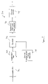
- FIG. 1 shows a prior art example of a multipath channel profile.
- the main signal cursor 102 is followed in time by post-cursors 104 , 106 , 108 , and 110 .
- DFE Decision Feedback Equalizer
- a DFE is relatively simple to implement and performs well under certain known circumstances. The performance of the DFE depends heavily on the characteristics of the channel.
- a DFE typically performs well over a minimum-phase channel, where the channel response has little energy in its pre-cursors, and its post-cursor energy decays with time.
- a DFE typically consists of a feed-forward filter (FFF) and a feedback filter (FBF). The FFF is used to help transform the channel into such a minimum-phase channel.
- FFF feed-forward filter
- BPF feedback filter
- Certain advantages of a DFE include good performance with relatively low complexity. Certain disadvantages include, but are not limited to: (1) Error propagation—i.e., once an error is made, that error is fed back and propagated into future symbol decisions. (2) Sub-optimum performance—i.e., instead of capturing multipath energy in the channel, the DFE instead cancels out this energy. (3) Hard decision output—i.e., a DFE makes a decision on the transmitted symbol without providing any information associated with the reliability of that decision.
- Equalizers include, but are not limited to, MLSE (Maximum Likelihood Sequence Estimation) and MAP (Maximum-A-Posterori) Estimation.
- MLSE Maximum Likelihood Sequence Estimation
- MAP Maximum-A-Posterori
- the complexity of the MLSE and MAP equalizers is exponentially proportional to the memory of the channel.
- the number of states required in the MLSE or MAP equalizer is given by M L , where M is the size of the symbol alphabet and L is the memory of the channel in symbols.
- the use of 8PSK modulation in the EDGE system makes the complexity of the MLSE and MAP equalizers very large for channels with moderate delay spreads.
- different channel models exist for different types of terrain and are used to quantify receiver sensitivity in the GSM standard. For example, the Hilly Terrain (HT) channel model has a profile that spans more than five symbols and would therefore require an MLSE or MAP equalizer with 32,768 states to achieve acceptable performance.
- HT Hilly Terrain
- equalizer device that provides for a simpler implementation, such as a DFE, but which provides the improved performance characteristics of a more complex equalizer, such as an MLSE or MAP.
- the equalizer should be generally applicable to all digital communication systems but provide particular advantage to coded systems using higher-order modulation schemes.
- the present invention describes an equalizer which combines the benefits of a decision feedback equalizer (DFE) with a maximum-a-posterori (MAP) equalizer (or a maximum likelihood sequence estimator, MLSE) to provide an equalization device with lower complexity than a full-state MAP or MLSE device, but which still provides improved performance over a pure DFE solution.
- DFE decision feedback equalizer
- MAP maximum-a-posterori
- MLSE maximum likelihood sequence estimator
- the equalizer architecture includes two DFE-like structures, followed by a MAP equalizer.
- the channel response is estimated and used to derive the coefficients of the feed-forward and feedback filters.
- the coefficients of the feedback filter of the second DFE are a subset of the coefficients of the first feedback filter.
- the first DFE acts like a conventional DFE and forms tentative symbol decisions.
- L 1 certain memory
- the effective channel response seen by the MAP equalizer is therefore constrained to a memory L 1 , and therefore the overall complexity of the equalizer is significantly reduced.
- the proposed equalizer degenerates to a conventional DFE.
- the proposed equalizer is a full state MAP equalizer. Therefore performance versus complexity trade-offs between a simple DFE and a full-state MAP equalizer can be made.
- An MLSE equalizer might also be used in place of the MAP equalizer in the described configuration, if further complexity reduction is desired. However, usage of the MLSE will come at the expense of receiver sensitivity.
- one aspect of the present invention provides for a reduced-state complexity equalizer apparatus for use with communication systems requiring equalization of a received incoming signal subject to intersymbol interference (ISI), the apparatus comprising: a first decision feedback equalizer device which utilizes coefficients derived from the estimated channel response and forms tentative symbol decisions; at least a second decision feedback equalizer device which utilizes coefficients derived from the estimated channel response and the tentative symbol decisions from the first decision feedback equalizer to truncate the channel response to a desired channel memory; at least one non-linear equalizer device for providing equalization of the channel response over the desired memory, whereby the overall complexity of the equalizer is reduced by reducing the effective delay spread of the channel.
- ISI intersymbol interference
- Still another aspect of the present invention provides for a method for reducing the complexity of an equalizer for use with a communication system requiring equalization of a received incoming signal subject to intersymbol interference (ISI), the method comprising the steps of: deriving feedback and feed-forward coefficients for the associated feedback and feed-forward filters of a first and at least one subsequent decision feedback equalizer from the estimated channel response; utilizing the first decision feedback equalizer to form tentative decisions regarding certain symbols; utilizing at least one subsequent decision feedback equalizer to truncate the channel response to a desired memory; utilizing at least one non-linear equalizer for providing equalization of the channel response over the desired memory, whereby the overall complexity of the equalizer is reduced by reducing the effective delay spread of the channel.
- ISI intersymbol interference
- FIG. 1 is a prior art representation of typical multipath channel with a time-decaying channel response.
- FIG. 2 is a prior art diagram of an EDGE burst structure.
- FIG. 3 is a prior art block diagram of representative transmitter, channel, and receiver.
- FIG. 4 is a prior art block diagram of representative transmitter elements.
- FIG. 5 is a prior art diagram of the encoding rule for an 8PSK modulator.
- FIG. 6 is a prior art diagram of the transmitted constellation for an 8PSK signal corresponding to FIG. 5 .
- FIG. 7 is a block diagram of representative EDGE receiver elements, wherein the channel estimation might incorporate certain aspects of the present invention.
- FIG. 8 is a prior art diagram of the auto-correlation of Training Sequences.
- FIG. 9 is a prior art block diagram of representative DFE elements, with an associated channel response after the feed-forward filter.
- FIG. 10 is a block diagram, according to one aspect of the present invention, of certain representative elements of an equalizer which combines a DFE with a MAP equalizer.
- FIG. 11 is a block diagram, according to one aspect of the present invention, of a representative channel response showing the resulting elements of the truncated channel.
- FIG. 12 is a block diagram, according to one aspect of the present invention, of certain representative elements of the present equalizer which combines a DFE with a MAP equalizer, and then also employs subsequent DFE/MAP equalizers, as needed.
- FIG. 13 is a flowchart, according to one aspect of the present invention, of certain representative steps that can be used to implement the present method of equalization.
- the present invention is described below in terms of certain preferred embodiments, and representative applications.
- the apparatus and processing methods are applicable to any wireless or wireline communication system where an equalizer is used to eliminate the ISI effects of the channel.
- the GSM/EDGE system uses a combination of Time- and Frequency-Division Multiple Access (TDMA/FDMA).
- TDMA/FDMA Time- and Frequency-Division Multiple Access
- the FDMA part involves the division by the frequency of the (maximum) 25 MHz bandwidth into 124 carrier frequencies spaced 200 kHz apart.
- One or more carrier frequencies is assigned to each base station. Each of these carrier frequencies is then divided in time, using a TDMA scheme.
- the fundamental unit of time in this TDMA scheme is called a burst period, and it lasts for 15/26 ms (or approximately 0.577 ms).
- Eight burst periods are grouped into a TDMA frame (120/26 ms, or approximately 4.615 ms) which forms the basic unit for the definition of logical channels.
- One physical channel is one burst period per TDMA frame.
- FIG. 2 shows a representative diagram 200 of an EDGE burst structure.
- One frame 202 is shown to include eight time slots.
- Each representative time slot 203 is shown to include a training sequence 204 of 26 symbols in the middle, three tail symbols 206 , 208 at either end, and 8.25 guard symbols 210 at one end.
- Each burst carries two sequences of 58 data symbols.
- the data sequences 212 and 214 are shown on either side of the training sequence 204 .
- FIG. 3 next shows a prior art block diagram 300 of a communication system that consists of a transmitter 304 , a channel 310 , and a receiver 320 .
- the signal s(t) 302 represents a sequence of information that is going to be transmitted over a channel.
- the transmitted signal encounters a channel 310 (which includes multiplicative, dispersive component 312 and additive white Gaussian noise component 314 ).
- the receiver 320 attempts to recover the original signal s(t) as received information bits 322 .
- FIG. 4 A more specific block diagram of the transmitter portion 400 is shown in FIG. 4 .
- the user data is first formatted into a frame via block 402 . Thereafter the data is convolutionally encoded and punctured as shown in block 404 .
- the signal is passed to an interleaver 406 that scrambles the coded bits and distributes them across four bursts, shown as the burst builder block 408 .
- the GMSK or 8PSK modulator is shown receiving the subsequent signal in block 410 .
- the modulating bits are mapped in groups of three to a single 8PSK symbol.
- the encoding rule is shown in FIG. 5 , where (d 3i , d 3i+1 , d 3i+2 ) are the output bits from the interleaver. These output symbols are then continuously rotated by a phase shift of 3/8 radians per symbol (the symbol rate is approximately 270.833 ksps). These rotating 8PSK symbols are then pulse-shaped, using a filter with an impulse response corresponding to the main component in a Laurant decomposition of a GMSK signal. As seen in FIG. 6 , this partial response signaling (caused by the pulse-shaping filter) causes the transmitted signal to have appreciable amounts of ISI.
- the transmitted signal thereafter passes through a multipath fading channel h(t) and is corrupted by additive white Gaussian Noise n(t).
- L is the span of the composite channel response (consisting of the cascade pulse-shaping filter, propagation channel and the receiver front-end filter)
- dn is the nth transmitted data symbol
- ⁇ h 0 , h 1 , . . . , h L ⁇ are the complex coefficients of the channel response
- ⁇ ⁇ is the complex, zero-mean, white Gaussian random variable.
- FIG. 7 A block diagram of a typical EDGE receiver 700 is shown in FIG. 7 .
- the received signal after analog-to-digital conversion, is passed through a digital low-pass filter 702 (or matched filter) to enhance the signal-to-noise ratio within the signal bandwidth of interest.
- a feed-forward filter (FFF) 704 is used to try to convert the channel to a minimum-phase channel.
- the FFF coefficients are computed in block 708 based on the channel estimates, which along with the sample timing are derived from the correlation of the received signal with a known training sequence.
- the output from the FFF is passed to an equalizer 706 , which attempts to eliminate the ISI having the composite response given by the transmitter pulse, the channel impulse response, and the receiver filter.
- the equalizer might be a DFE, MLSE, or MAP.
- the output from the equalizer is then reassembled into a frame, and a deinterleaver is applied (if needed). This signal is then passed to the channel decoder 712 , if channel coding was applied at the transmitter.
- Timing recovery and channel estimation are performed with the aid of the training sequence 204 (in FIG. 2 ).
- the training sequence has the property that the result of correlating the middle 16 symbols with the entire training sequence yields a correlation function with identically zero values for +/ ⁇ 5 symbols around the peak 802 , as shown in FIG. 8 .
- the oversampled received signal is correlated with the stored training sequence.
- the optimal symbol timing is given by the index of the subsample with the largest correlation value.
- the estimates of the channel response i.e., ⁇ h 0 , h 1 , . . . , h L ⁇ are given by a window of L+1 symbol-spaced correlation values with the largest sum of energy. Since the auto-correlation values given by the training sequence are approximately zero for up to +/ ⁇ 7 symbols around the peak 802 , the maximum window size L may be as large as 7. Since the duration of the burst is 0.577 ms, the channel can be assumed to be stationary during the burst for most vehicle speeds of practical interest.
- FIG. 9 shows a representative prior art block diagram 900 of a DFE device, which might be used as the equalizer device above.
- a standard DFE consists of two filters, a feed-forward filter (FFF) 902 and a feedback filter (FBF) 904 .
- the FFF is generally designed to act as a whitened matched filter to the received incoming signal, thus maximizing the signal to noise ratio, while keeping the statistical properties of the noise Gaussian with zero mean.
- a representative signal (with interference) which might exist after the FFF is shown as 903 , with signal rays h 0 , h 1 , h 2 , and h 3 .
- the FBF 904 is used to reconstruct post-cursor interference using decisions made on previously detected symbols. After filtering 904 , the post-cursor interference is subtracted from the output of FFF 902 , and a symbol decision 908 is made on this output.
- ⁇ circumflex over (d) ⁇ n denotes the decision made on the symbol d n .
- the number of the feedback coefficients N b may be different from the memory of the overall channel response L.
- N b L.
- the coefficients of the FFF and the FBF for the DFE can be computed using a variety of computationally efficient methods. One such method entitled “Fast Computation of Channel-Estimate Based Equalizers in Packet Data Transmission” has already been incorporated by reference above.
- the soft value is a function of the channel coefficients.
- Other examples include making the soft value proportional to the energy gain of the channel.
- An MLSE is the optimum equalizer in the presence of finite ISI and white Gaussian noise.
- the equalizer consists of a matched filter followed by a Viterbi algorithm.
- the complexity of the equalizer is determined by the number of states of the Viterbi algorithm, M L , where M is the symbol alphabet size and L is the memory of the channel. For high order modulations, such as 8PSK and 16QAM, the complexity of the equalizer is very large, even for moderate values of L.
- the MAP criterion may be applied, resulting in an equalizer that has the same order of the complexity as the MLSE, but is able to produce soft symbol outputs.
- the soft symbol values improve the performance of the subsequent channel decoder for a coded system.
- the optimal path metric can be computed using the method described by Ungerboeck (see Gottfried Ungerboeck, “Adaptive maximum-likelihood receiver for carrier-modulated data-transmission system,” IEEE Transactions on Communications, vol. COM-22, No. 5, pp. 624–636, May 1974).
- the hard symbol decisions output from the equalizer are weighed according to Equation (3) prior to being passed to the channel decoder.
- the MLSE/MAP equalizers typically achieve better performance over a DFE. Nevertheless, they are significantly more complex to implement than the DFE for the same channel memory.
- the proposed approach for equalizing 8PSK (or other such high-order) modulation signals consists of a combination of a DFE with a MAP equalizer (DFE-MAP).
- DFE-MAP a MAP equalizer
- FIG. 10 A block diagram of an embodiment of the present invention 1000 is shown in FIG. 10 .
- the equalizer architecture consists of two DFE-like structures 1002 and 1004 , followed by a MAP equalizer 1006 .
- a feed-forward filter is shown as 1008 .
- the first DFE 1002 acts like a conventional DFE and forms tentative symbol decisions.
- the coefficients of the feed-forward filter 1008 and the first feedback filter 1010 are derived from the channel estimates, as in the conventional DFE case.
- the coefficients of the second feedback filter 1014 are a subset of the coefficients of the first feedback filter 1010 .
- the input to the decision process 1012 is thus given by the prior Equation (2).
- a sample channel response 1050 is shown after the feed-forward filter 1008 , containing signal rays h 0 through h 4 .
- the first DFE structure 1002 serves to first provide feedback signals through the first feedback filter 1010 as shown by the signal rays h 1 through h 4 in 1052 .
- the purpose of the second feedback filter 1014 is to eliminate the impact of post-cursors (e.g., h 3 and h 4 , shown by 1054 ) beyond L 1 symbols (e.g., set at h 2 ), and thereby truncating the channel response to a desired memory of L 1 symbols.
- the filter does this by canceling these post-cursors using the tentative decisions ⁇ circumflex over (d) ⁇ k formed by the first DFE.
- Equation (4) This is achieved by breaking the received signal after the feed-forward filter 1008 into two parts, as shown by Equation (4), and thereafter constraining the maximum number of states in the MAP equalizer to be M L1 states out of a maximum possible of M L for the full state space.
- ⁇ is the noise sample at the symbol rate after passage through the whitened-matched filter.
- a tentative estimate of the data sequence, ⁇ circumflex over (d) ⁇ n ⁇ is produced by the first DFE structure 1002 (using hard symbols decisions of the z n output of Equation (2)), and together with the feedback coefficients, ⁇ b k ⁇ , is used to limit the duration of the intersymbol interference to L 1 symbols.
- a conventional MAP equalizer would require 8 (5 ⁇ 1) states, or 4096 states.
- the effective channel memory seen by the MAP would be reduced to 3 (see signal 1356 ) and the equalizer would only require 8 (3 ⁇ 1) states, or 64 states.
- the proposed equalizer configuration would be much more manageable and less complex to implement.
- FIG. 11 next shows a graphical representation 1100 of this representative channel response having elements h 0 through h 4 .
- L 1 L ( 1102 )
- the proposed equalizer degenerates to a conventional DFE
- the value of the L 1 L ( 1104 )
- the proposed equalizer is a full-state MAP equalizer.
- FIG. 12 shows a block diagram having substantially the same components (similarly numbered) as FIG. 10 .
- a subsequent feedback filter 1204 is shown.
- the results of this subsequent feedback filter 1204 are then subtracted from the output of the feed-forward filter 1008 .
- This signal is then fed into a subsequent MAP equalizer 1208 to provide a result 1212 which provides even better performance characteristics.
- arrows 1208 and 1210 are meant to indicate that even more feedback filters and MAP equalizers might be added, if further processing is needed. Note that the addition of such subsequent filters will increase the complexity of implementation, but (again) may provide for increased performance up to certain limits, wherein additional filters will not be worth their implementation cost.
- FIG. 13 next shows a representative flowchart of certain steps 1300 that might be used to implement the present invention.
- step 1302 an estimate is taken of the channel, which is shown receiving an incoming signal 1301 , as per the general approaches described above.
- step 1304 the feedback and feed-forward coefficients are derived for the associated filters of the DFEs, based upon the estimate of the channel response.
- step 1306 the signal passes through a feed-forward filter whose coefficients have been determined above.
- a first DFE including at least a feedback filter and decision process
- Step 1310 shows the second DFE being used to cancel (or subtract) certain distant post-cursors.
- Step 1312 next runs a MAP equalizer on this truncated channel. Thereafter the resulting signal might be utilized ( 1314 ) as an equalized signal in any system that might require such an equalized signal.
- Step 1315 Certain optional steps for implementation are shown in block 1315 .
- Step 1316 is shown canceling certain distant post-cursors (again, like 1310 ). This would be achieved by subsequent implementations of DFE components (i.e., feedback filters in association with feed-forward filters, and linear equalizers) as implied by the arrows 1208 and 1210 in FIG. 12 .
- Block 1318 next shows the step of utilizing a subsequent MAP equalizer on the constrained signal.
- Decision block 1320 inquires whether further processing is needed (or desired). If yes, then steps 1316 and 1318 can be repeated as many times as might be needed with subsequent equalizer implementations (again referring to elements 1208 , 1210 in FIG. 12 ). If no further processing is needed, then the flow proceeds to step 1314 where the resulting equalized signal is utilized.
Abstract
Description
where L is the span of the composite channel response (consisting of the cascade pulse-shaping filter, propagation channel and the receiver front-end filter), dn is the nth transmitted data symbol, {h0, h1, . . . , hL} are the complex coefficients of the channel response, and ηη is the complex, zero-mean, white Gaussian random variable.
where fk, k=−Nf, . . . , 0 are the coefficients of the feed-forward filter, bk, k=1, . . . , Nb are the coefficients of the feedback filter, and {circumflex over (d)}n denotes the decision made on the symbol dn. The number of the feedback coefficients Nb may be different from the memory of the overall channel response L. Hereafter, we will assume Nb=L. The coefficients of the FFF and the FBF for the DFE can be computed using a variety of computationally efficient methods. One such method entitled “Fast Computation of Channel-Estimate Based Equalizers in Packet Data Transmission” has already been incorporated by reference above.
where yn is the output of the matched filter, αn is the hypothetical input symbol and αn−i, i=1, . . . , L is given by the state of the trellis, and si is given by the following convolution:
where φ is the noise sample at the symbol rate after passage through the whitened-matched filter.
where L1<=L. Since the MAP equalizer now operates only on ML1 states, the overall complexity of the equalizer is significantly reduced.
Claims (14)
Priority Applications (7)
| Application Number | Priority Date | Filing Date | Title |
|---|---|---|---|
| US09/941,300 US7012957B2 (en) | 2001-02-01 | 2001-08-27 | High performance equalizer having reduced complexity |
| DE60235667T DE60235667D1 (en) | 2001-02-01 | 2002-01-16 | Equalization with shortening of the impulse response |
| EP20020250310 EP1229699B1 (en) | 2001-02-01 | 2002-01-16 | Equalisation with impulse-response shortening |
| EP20020252260 EP1246418B1 (en) | 2001-03-29 | 2002-03-27 | Hybrid equaliser with feedback and sequence estimation |
| DE60234888T DE60234888D1 (en) | 2001-03-29 | 2002-03-27 | Hybrid equalizer with feedback and follow-up estimation |
| US11/376,002 US7656943B2 (en) | 2001-02-01 | 2006-03-14 | High performance equalizer having reduced complexity |
| US12/698,229 US8582636B2 (en) | 2001-02-01 | 2010-02-02 | High performance equalizer having reduced complexity |
Applications Claiming Priority (4)
| Application Number | Priority Date | Filing Date | Title |
|---|---|---|---|
| US26573601P | 2001-02-01 | 2001-02-01 | |
| US26574001P | 2001-02-01 | 2001-02-01 | |
| US27990701P | 2001-03-29 | 2001-03-29 | |
| US09/941,300 US7012957B2 (en) | 2001-02-01 | 2001-08-27 | High performance equalizer having reduced complexity |
Related Child Applications (1)
| Application Number | Title | Priority Date | Filing Date |
|---|---|---|---|
| US11/376,002 Continuation US7656943B2 (en) | 2001-02-01 | 2006-03-14 | High performance equalizer having reduced complexity |
Publications (2)
| Publication Number | Publication Date |
|---|---|
| US20020131489A1 US20020131489A1 (en) | 2002-09-19 |
| US7012957B2 true US7012957B2 (en) | 2006-03-14 |
Family
ID=27500865
Family Applications (3)
| Application Number | Title | Priority Date | Filing Date |
|---|---|---|---|
| US09/941,300 Expired - Lifetime US7012957B2 (en) | 2001-02-01 | 2001-08-27 | High performance equalizer having reduced complexity |
| US11/376,002 Expired - Fee Related US7656943B2 (en) | 2001-02-01 | 2006-03-14 | High performance equalizer having reduced complexity |
| US12/698,229 Expired - Fee Related US8582636B2 (en) | 2001-02-01 | 2010-02-02 | High performance equalizer having reduced complexity |
Family Applications After (2)
| Application Number | Title | Priority Date | Filing Date |
|---|---|---|---|
| US11/376,002 Expired - Fee Related US7656943B2 (en) | 2001-02-01 | 2006-03-14 | High performance equalizer having reduced complexity |
| US12/698,229 Expired - Fee Related US8582636B2 (en) | 2001-02-01 | 2010-02-02 | High performance equalizer having reduced complexity |
Country Status (1)
| Country | Link |
|---|---|
| US (3) | US7012957B2 (en) |
Cited By (14)
| Publication number | Priority date | Publication date | Assignee | Title |
|---|---|---|---|---|
| US20020196877A1 (en) * | 2001-03-29 | 2002-12-26 | Applied Wave Research, Inc. | Method and apparatus for characterizing the distortion produced by electronic equipment |
| US20030227967A1 (en) * | 2002-06-06 | 2003-12-11 | Chin-Liang Wang | System and method for time-domain equalization in discrete multi-tone system |
| US20040071231A1 (en) * | 2002-10-11 | 2004-04-15 | Jingdong Lin | Receiver signal dynamic range compensation based on received signal strength indicator |
| US20040120432A1 (en) * | 2001-03-06 | 2004-06-24 | Christophe Laot | Equalising and decoding device for frequency-selective channels |
| US20040247026A1 (en) * | 2003-06-06 | 2004-12-09 | Axel Kochale | Bit recovery scheme for an asymmetric data channel |
| US20050226316A1 (en) * | 2004-04-09 | 2005-10-13 | Sony Corporation | Adaptive equalizing apparatus and method |
| US20060176949A1 (en) * | 2001-02-01 | 2006-08-10 | Stephen Allpress | High performance equalizer having reduced complexity |
| US20070030890A1 (en) * | 2005-08-05 | 2007-02-08 | Nec Corporation | Partial response transmission system and equalizing circuit thereof |
| US20070058584A1 (en) * | 2005-09-12 | 2007-03-15 | Ilan Sutskover | Techniques to transmit and duplex with channel knowledge at a base station |
| US7212569B1 (en) * | 2002-06-28 | 2007-05-01 | At&T Corp. | Frequency domain decision feedback equalizer |
| US20100226422A1 (en) * | 2005-06-29 | 2010-09-09 | Felix Alexandrovich Taubin | Precoder Construction And Equalization |
| US20100248664A1 (en) * | 2009-03-31 | 2010-09-30 | Paul Wilkinson Dent | Diversity receivers and methods for relatively-delayed signals |
| CN101958862A (en) * | 2010-10-22 | 2011-01-26 | 上海交通大学 | Self-adaptive decision feedback equalizer based on superposing structure |
| US20120281745A1 (en) * | 2009-01-06 | 2012-11-08 | The Directv Group, Inc. | Frequency drift estimation for low cost outdoor unit frequency conversions and system diagnostics |
Families Citing this family (26)
| Publication number | Priority date | Publication date | Assignee | Title |
|---|---|---|---|---|
| US20030115061A1 (en) * | 2001-09-11 | 2003-06-19 | Broadcom Corporation | MPSK equalizer |
| SE0201103D0 (en) * | 2002-04-11 | 2002-04-11 | Ericsson Telefon Ab L M | Diagonally Layered Multi-Antenna Transmission for Frequency Selective Channels |
| US20050076149A1 (en) * | 2002-12-04 | 2005-04-07 | Macphy Technologies, Inc. | Method and apparatus for providing broadband wireless access services using the low voltage power line |
| GB0229320D0 (en) * | 2002-12-17 | 2003-01-22 | Koninkl Philips Electronics Nv | Signal processing method and apparatus |
| US7187736B2 (en) * | 2003-02-13 | 2007-03-06 | Motorola Inc. | Reducing interference in a GSM communication system |
| US6944245B2 (en) | 2003-10-17 | 2005-09-13 | Motorola, Inc. | Multi-pass interference reduction in a GSM communication system |
| US20060242406A1 (en) * | 2005-04-22 | 2006-10-26 | Microsoft Corporation | Protected computing environment |
| US8379709B2 (en) * | 2008-09-04 | 2013-02-19 | Telefonaktiebolaget L M Ericsson (Publ) | Channel estimation and equalization for hard-limited signals |
| KR101363122B1 (en) * | 2010-06-29 | 2014-02-13 | 한국전자통신연구원 | Apparatus and Method of equalizing applied adaptation algorithm for high speed transmission |
| US8699634B2 (en) | 2011-06-30 | 2014-04-15 | Harris Corporation | Wireless communications device having map trellis decoder with partial sum tables and related methods |
| US8599914B1 (en) | 2012-06-20 | 2013-12-03 | MagnaCom Ltd. | Feed forward equalization for highly-spectrally-efficient communications |
| US8681889B2 (en) | 2012-06-20 | 2014-03-25 | MagnaCom Ltd. | Multi-mode orthogonal frequency division multiplexing receiver for highly-spectrally-efficient communications |
| US9166834B2 (en) | 2012-06-20 | 2015-10-20 | MagnaCom Ltd. | Method and system for corrupt symbol handling for providing high reliability sequences |
| US8781008B2 (en) | 2012-06-20 | 2014-07-15 | MagnaCom Ltd. | Highly-spectrally-efficient transmission using orthogonal frequency division multiplexing |
| US9088400B2 (en) | 2012-11-14 | 2015-07-21 | MagnaCom Ltd. | Hypotheses generation based on multidimensional slicing |
| US8811548B2 (en) | 2012-11-14 | 2014-08-19 | MagnaCom, Ltd. | Hypotheses generation based on multidimensional slicing |
| US9154346B2 (en) * | 2013-03-13 | 2015-10-06 | Nikola Alic | Method for reducing equalizer complexity in communication links |
| US9118519B2 (en) | 2013-11-01 | 2015-08-25 | MagnaCom Ltd. | Reception of inter-symbol-correlated signals using symbol-by-symbol soft-output demodulator |
| US8804879B1 (en) | 2013-11-13 | 2014-08-12 | MagnaCom Ltd. | Hypotheses generation based on multidimensional slicing |
| US9130637B2 (en) | 2014-01-21 | 2015-09-08 | MagnaCom Ltd. | Communication methods and systems for nonlinear multi-user environments |
| US9496900B2 (en) | 2014-05-06 | 2016-11-15 | MagnaCom Ltd. | Signal acquisition in a multimode environment |
| US8891701B1 (en) | 2014-06-06 | 2014-11-18 | MagnaCom Ltd. | Nonlinearity compensation for reception of OFDM signals |
| US9246523B1 (en) | 2014-08-27 | 2016-01-26 | MagnaCom Ltd. | Transmitter signal shaping |
| US9276619B1 (en) | 2014-12-08 | 2016-03-01 | MagnaCom Ltd. | Dynamic configuration of modulation and demodulation |
| US9191247B1 (en) | 2014-12-09 | 2015-11-17 | MagnaCom Ltd. | High-performance sequence estimation system and method of operation |
| CN112567703A (en) * | 2018-08-17 | 2021-03-26 | 拉姆伯斯公司 | Multi-stage equalizer for intersymbol interference cancellation |
Citations (9)
| Publication number | Priority date | Publication date | Assignee | Title |
|---|---|---|---|---|
| US4905254A (en) * | 1987-06-09 | 1990-02-27 | U.S. Philips Corporation | Arrangement for combating intersymbol interference and noise |
| US5031195A (en) * | 1989-06-05 | 1991-07-09 | International Business Machines Corporation | Fully adaptive modem receiver using whitening matched filtering |
| US5513215A (en) * | 1993-09-20 | 1996-04-30 | Glenayre Electronics, Inc. | High speed simulcast data system using adaptive compensation |
| US5513214A (en) * | 1992-03-05 | 1996-04-30 | Loral Federal Systems Company | System and method of estimating equalizer performance in the presence of channel mismatch |
| US6301315B1 (en) * | 1999-12-22 | 2001-10-09 | At&T Corp. | Methods and systems for symbol estimation in a receiver |
| US20020131488A1 (en) * | 2001-02-01 | 2002-09-19 | Allpress Steve A. | Decision feedback equalizer for minimum and maximum phase channels |
| US20020131490A1 (en) * | 2001-02-01 | 2002-09-19 | Allpress Steve A. | High performance equalizer with enhanced DFE having reduced complexity |
| US6535554B1 (en) * | 1998-11-17 | 2003-03-18 | Harris Corporation | PCS signal separation in a one dimensional channel |
| US6608862B1 (en) * | 1999-08-20 | 2003-08-19 | Ericsson, Inc. | Method and apparatus for computing prefilter coefficients |
Family Cites Families (1)
| Publication number | Priority date | Publication date | Assignee | Title |
|---|---|---|---|---|
| US7012957B2 (en) * | 2001-02-01 | 2006-03-14 | Broadcom Corporation | High performance equalizer having reduced complexity |
-
2001
- 2001-08-27 US US09/941,300 patent/US7012957B2/en not_active Expired - Lifetime
-
2006
- 2006-03-14 US US11/376,002 patent/US7656943B2/en not_active Expired - Fee Related
-
2010
- 2010-02-02 US US12/698,229 patent/US8582636B2/en not_active Expired - Fee Related
Patent Citations (9)
| Publication number | Priority date | Publication date | Assignee | Title |
|---|---|---|---|---|
| US4905254A (en) * | 1987-06-09 | 1990-02-27 | U.S. Philips Corporation | Arrangement for combating intersymbol interference and noise |
| US5031195A (en) * | 1989-06-05 | 1991-07-09 | International Business Machines Corporation | Fully adaptive modem receiver using whitening matched filtering |
| US5513214A (en) * | 1992-03-05 | 1996-04-30 | Loral Federal Systems Company | System and method of estimating equalizer performance in the presence of channel mismatch |
| US5513215A (en) * | 1993-09-20 | 1996-04-30 | Glenayre Electronics, Inc. | High speed simulcast data system using adaptive compensation |
| US6535554B1 (en) * | 1998-11-17 | 2003-03-18 | Harris Corporation | PCS signal separation in a one dimensional channel |
| US6608862B1 (en) * | 1999-08-20 | 2003-08-19 | Ericsson, Inc. | Method and apparatus for computing prefilter coefficients |
| US6301315B1 (en) * | 1999-12-22 | 2001-10-09 | At&T Corp. | Methods and systems for symbol estimation in a receiver |
| US20020131488A1 (en) * | 2001-02-01 | 2002-09-19 | Allpress Steve A. | Decision feedback equalizer for minimum and maximum phase channels |
| US20020131490A1 (en) * | 2001-02-01 | 2002-09-19 | Allpress Steve A. | High performance equalizer with enhanced DFE having reduced complexity |
Cited By (28)
| Publication number | Priority date | Publication date | Assignee | Title |
|---|---|---|---|---|
| US20100202507A1 (en) * | 2001-02-01 | 2010-08-12 | Stephen Allpress | High Performance Equalizer Having Reduced Complexity |
| US8582636B2 (en) * | 2001-02-01 | 2013-11-12 | Broadcom Corporation | High performance equalizer having reduced complexity |
| US20060176949A1 (en) * | 2001-02-01 | 2006-08-10 | Stephen Allpress | High performance equalizer having reduced complexity |
| US7656943B2 (en) * | 2001-02-01 | 2010-02-02 | Broadcom Corporation | High performance equalizer having reduced complexity |
| US20040120432A1 (en) * | 2001-03-06 | 2004-06-24 | Christophe Laot | Equalising and decoding device for frequency-selective channels |
| US7561647B2 (en) * | 2001-03-06 | 2009-07-14 | France Telecom | Equalising and decoding device for frequency-selective channels |
| US20020196877A1 (en) * | 2001-03-29 | 2002-12-26 | Applied Wave Research, Inc. | Method and apparatus for characterizing the distortion produced by electronic equipment |
| US7577192B2 (en) * | 2001-03-29 | 2009-08-18 | Applied Wave Research, Inc. | Method and apparatus for characterizing the distortion produced by electronic equipment |
| US20030227967A1 (en) * | 2002-06-06 | 2003-12-11 | Chin-Liang Wang | System and method for time-domain equalization in discrete multi-tone system |
| US7212569B1 (en) * | 2002-06-28 | 2007-05-01 | At&T Corp. | Frequency domain decision feedback equalizer |
| US7418035B1 (en) * | 2002-06-28 | 2008-08-26 | At&T Corp. | Frequency domain decision feedback equalizer |
| US20040071231A1 (en) * | 2002-10-11 | 2004-04-15 | Jingdong Lin | Receiver signal dynamic range compensation based on received signal strength indicator |
| US7200194B2 (en) * | 2002-10-11 | 2007-04-03 | Spreadtrum Communications Corporation | Receiver signal dynamic range compensation based on received signal strength indicator |
| US20040247026A1 (en) * | 2003-06-06 | 2004-12-09 | Axel Kochale | Bit recovery scheme for an asymmetric data channel |
| US7286598B2 (en) * | 2003-06-06 | 2007-10-23 | Thomson Licensing | Bit recovery scheme for an asymmetric data channel |
| US7551668B2 (en) * | 2004-04-09 | 2009-06-23 | Sony Corporation | Adaptive equalizing apparatus and method |
| US20050226316A1 (en) * | 2004-04-09 | 2005-10-13 | Sony Corporation | Adaptive equalizing apparatus and method |
| US8681849B2 (en) * | 2005-06-29 | 2014-03-25 | Intel Corporation | Precoder construction and equalization |
| US20100226422A1 (en) * | 2005-06-29 | 2010-09-09 | Felix Alexandrovich Taubin | Precoder Construction And Equalization |
| US20070030890A1 (en) * | 2005-08-05 | 2007-02-08 | Nec Corporation | Partial response transmission system and equalizing circuit thereof |
| US7590176B2 (en) * | 2005-08-05 | 2009-09-15 | Nec Corporation | Partial response transmission system and equalizing circuit thereof |
| US20070058584A1 (en) * | 2005-09-12 | 2007-03-15 | Ilan Sutskover | Techniques to transmit and duplex with channel knowledge at a base station |
| US20120281745A1 (en) * | 2009-01-06 | 2012-11-08 | The Directv Group, Inc. | Frequency drift estimation for low cost outdoor unit frequency conversions and system diagnostics |
| US8509722B2 (en) * | 2009-01-06 | 2013-08-13 | The Directv Group, Inc. | Frequency drift estimation for low cost outdoor unit frequency conversions and system diagnostics |
| US20100248664A1 (en) * | 2009-03-31 | 2010-09-30 | Paul Wilkinson Dent | Diversity receivers and methods for relatively-delayed signals |
| US8369459B2 (en) | 2009-03-31 | 2013-02-05 | Telefonaktiebolaget L M Ericsson (Publ) | Diversity receivers and methods for relatively-delayed signals |
| CN101958862A (en) * | 2010-10-22 | 2011-01-26 | 上海交通大学 | Self-adaptive decision feedback equalizer based on superposing structure |
| CN101958862B (en) * | 2010-10-22 | 2012-11-28 | 上海交通大学 | Self-adaptive decision feedback equalizer based on superposing structure |
Also Published As
| Publication number | Publication date |
|---|---|
| US20100202507A1 (en) | 2010-08-12 |
| US20020131489A1 (en) | 2002-09-19 |
| US20060176949A1 (en) | 2006-08-10 |
| US8582636B2 (en) | 2013-11-12 |
| US7656943B2 (en) | 2010-02-02 |
Similar Documents
| Publication | Publication Date | Title |
|---|---|---|
| US7012957B2 (en) | High performance equalizer having reduced complexity | |
| US8121182B2 (en) | High performance equalizer with enhanced DFE having reduced complexity | |
| US7230982B2 (en) | Decision feedback equalizer for minimum and maximum phase channels | |
| Vitetta et al. | Maximum likelihood decoding of uncoded and coded PSK signal sequences transmitted over Rayleigh flat-fading channels | |
| Fragouli et al. | Prefiltered space-time M-BCJR equalizer for frequency-selective channels | |
| US7292661B1 (en) | Block-iterative equalizers for digital communication system | |
| EP1246418B1 (en) | Hybrid equaliser with feedback and sequence estimation | |
| Miller et al. | Estimation of co-channel signals with linear complexity | |
| Schniter et al. | Equalization of time-varying channels | |
| EP1229699B1 (en) | Equalisation with impulse-response shortening | |
| Cusani et al. | Equalization of digital radio channels with large multipath delay for cellular land mobile applications | |
| EP1331777A1 (en) | DFE/MLSE equaliser | |
| Hart et al. | Innovations-based MAP detection for time-varying frequency-selective channels | |
| Otnes et al. | Block SISO linear equalizers for turbo equalization in serial-tone HF modems | |
| Heath et al. | Adaptive blind channel identification of FIR channels for Viterbi decoding | |
| Strauch et al. | Iterative channel estimation for EGPRS | |
| Castoldi et al. | On recursive optimal detection of linear modulations in the presence of random fading | |
| Mak et al. | Detection of trellis-coded modulation on time-dispersive channels | |
| Driscoll et al. | Detection processes for V32 modems using trellis coding | |
| Benvenuto et al. | Performance of the multitrellis Viterbi algorithm for sparse channels | |
| Marandian et al. | Low complexity iterative decision feedback equalizer for 8PSK modulation in time dispersive channels | |
| Benvenuto et al. | Multitrellis decomposition of the Viterbi algorithm for multipath channels | |
| Park et al. | Concatenation of MLSE equalizer and Viterbi decoder for TDMA cellular systems | |
| Rahnema | Channel equalization for the GSM system | |
| Ghosh | Joint equalization and decoding for complementary code keying (CCK) modulation |
Legal Events
| Date | Code | Title | Description |
|---|---|---|---|
| AS | Assignment |
Owner name: BROADCOM CORPORATION, CALIFORNIA Free format text: ASSIGNMENT OF ASSIGNORS INTEREST;ASSIGNORS:ALLPRESS, STEVE A.;LI, QUINN;REEL/FRAME:012499/0300 Effective date: 20010827 |
|
| STCF | Information on status: patent grant |
Free format text: PATENTED CASE |
|
| CC | Certificate of correction | ||
| CC | Certificate of correction | ||
| CC | Certificate of correction | ||
| CC | Certificate of correction | ||
| FPAY | Fee payment |
Year of fee payment: 4 |
|
| FPAY | Fee payment |
Year of fee payment: 8 |
|
| AS | Assignment |
Owner name: BANK OF AMERICA, N.A., AS COLLATERAL AGENT, NORTH CAROLINA Free format text: PATENT SECURITY AGREEMENT;ASSIGNOR:BROADCOM CORPORATION;REEL/FRAME:037806/0001 Effective date: 20160201 Owner name: BANK OF AMERICA, N.A., AS COLLATERAL AGENT, NORTH Free format text: PATENT SECURITY AGREEMENT;ASSIGNOR:BROADCOM CORPORATION;REEL/FRAME:037806/0001 Effective date: 20160201 |
|
| AS | Assignment |
Owner name: AVAGO TECHNOLOGIES GENERAL IP (SINGAPORE) PTE. LTD., SINGAPORE Free format text: ASSIGNMENT OF ASSIGNORS INTEREST;ASSIGNOR:BROADCOM CORPORATION;REEL/FRAME:041706/0001 Effective date: 20170120 Owner name: AVAGO TECHNOLOGIES GENERAL IP (SINGAPORE) PTE. LTD Free format text: ASSIGNMENT OF ASSIGNORS INTEREST;ASSIGNOR:BROADCOM CORPORATION;REEL/FRAME:041706/0001 Effective date: 20170120 |
|
| AS | Assignment |
Owner name: BROADCOM CORPORATION, CALIFORNIA Free format text: TERMINATION AND RELEASE OF SECURITY INTEREST IN PATENTS;ASSIGNOR:BANK OF AMERICA, N.A., AS COLLATERAL AGENT;REEL/FRAME:041712/0001 Effective date: 20170119 |
|
| MAFP | Maintenance fee payment |
Free format text: PAYMENT OF MAINTENANCE FEE, 12TH YEAR, LARGE ENTITY (ORIGINAL EVENT CODE: M1553) Year of fee payment: 12 |
|
| AS | Assignment |
Owner name: AVAGO TECHNOLOGIES INTERNATIONAL SALES PTE. LIMITE Free format text: MERGER;ASSIGNOR:AVAGO TECHNOLOGIES GENERAL IP (SINGAPORE) PTE. LTD.;REEL/FRAME:047196/0097 Effective date: 20180509 |
|
| AS | Assignment |
Owner name: AVAGO TECHNOLOGIES INTERNATIONAL SALES PTE. LIMITE Free format text: CORRECTIVE ASSIGNMENT TO CORRECT THE EXECUTION DATE PREVIOUSLY RECORDED AT REEL: 047196 FRAME: 0097. ASSIGNOR(S) HEREBY CONFIRMS THE MERGER;ASSIGNOR:AVAGO TECHNOLOGIES GENERAL IP (SINGAPORE) PTE. LTD.;REEL/FRAME:048555/0510 Effective date: 20180905 |