US7033322B2 - Implantable sensor - Google Patents
Implantable sensor Download PDFInfo
- Publication number
- US7033322B2 US7033322B2 US10/041,036 US4103601A US7033322B2 US 7033322 B2 US7033322 B2 US 7033322B2 US 4103601 A US4103601 A US 4103601A US 7033322 B2 US7033322 B2 US 7033322B2
- Authority
- US
- United States
- Prior art keywords
- sensor
- implantable sensor
- support structures
- implantable
- tubular
- Prior art date
- Legal status (The legal status is an assumption and is not a legal conclusion. Google has not performed a legal analysis and makes no representation as to the accuracy of the status listed.)
- Expired - Lifetime, expires
Links
- GPRLSGONYQIRFK-UHFFFAOYSA-N [H+] Chemical compound [H+] GPRLSGONYQIRFK-UHFFFAOYSA-N 0.000 description 1
Images


Classifications
-
- A—HUMAN NECESSITIES
- A61—MEDICAL OR VETERINARY SCIENCE; HYGIENE
- A61B—DIAGNOSIS; SURGERY; IDENTIFICATION
- A61B5/00—Measuring for diagnostic purposes; Identification of persons
- A61B5/145—Measuring characteristics of blood in vivo, e.g. gas concentration, pH value; Measuring characteristics of body fluids or tissues, e.g. interstitial fluid, cerebral tissue
- A61B5/1486—Measuring characteristics of blood in vivo, e.g. gas concentration, pH value; Measuring characteristics of body fluids or tissues, e.g. interstitial fluid, cerebral tissue using enzyme electrodes, e.g. with immobilised oxidase
- A61B5/14865—Measuring characteristics of blood in vivo, e.g. gas concentration, pH value; Measuring characteristics of body fluids or tissues, e.g. interstitial fluid, cerebral tissue using enzyme electrodes, e.g. with immobilised oxidase invasive, e.g. introduced into the body by a catheter or needle or using implanted sensors
-
- A—HUMAN NECESSITIES
- A61—MEDICAL OR VETERINARY SCIENCE; HYGIENE
- A61B—DIAGNOSIS; SURGERY; IDENTIFICATION
- A61B5/00—Measuring for diagnostic purposes; Identification of persons
- A61B5/0002—Remote monitoring of patients using telemetry, e.g. transmission of vital signals via a communication network
- A61B5/0031—Implanted circuitry
-
- A—HUMAN NECESSITIES
- A61—MEDICAL OR VETERINARY SCIENCE; HYGIENE
- A61B—DIAGNOSIS; SURGERY; IDENTIFICATION
- A61B5/00—Measuring for diagnostic purposes; Identification of persons
- A61B5/68—Arrangements of detecting, measuring or recording means, e.g. sensors, in relation to patient
- A61B5/6846—Arrangements of detecting, measuring or recording means, e.g. sensors, in relation to patient specially adapted to be brought in contact with an internal body part, i.e. invasive
- A61B5/6847—Arrangements of detecting, measuring or recording means, e.g. sensors, in relation to patient specially adapted to be brought in contact with an internal body part, i.e. invasive mounted on an invasive device
- A61B5/6862—Stents
-
- A—HUMAN NECESSITIES
- A61—MEDICAL OR VETERINARY SCIENCE; HYGIENE
- A61B—DIAGNOSIS; SURGERY; IDENTIFICATION
- A61B5/00—Measuring for diagnostic purposes; Identification of persons
- A61B5/68—Arrangements of detecting, measuring or recording means, e.g. sensors, in relation to patient
- A61B5/6846—Arrangements of detecting, measuring or recording means, e.g. sensors, in relation to patient specially adapted to be brought in contact with an internal body part, i.e. invasive
- A61B5/6867—Arrangements of detecting, measuring or recording means, e.g. sensors, in relation to patient specially adapted to be brought in contact with an internal body part, i.e. invasive specially adapted to be attached or implanted in a specific body part
- A61B5/6876—Blood vessel
-
- A—HUMAN NECESSITIES
- A61—MEDICAL OR VETERINARY SCIENCE; HYGIENE
- A61B—DIAGNOSIS; SURGERY; IDENTIFICATION
- A61B2560/00—Constructional details of operational features of apparatus; Accessories for medical measuring apparatus
- A61B2560/02—Operational features
- A61B2560/0204—Operational features of power management
- A61B2560/0214—Operational features of power management of power generation or supply
- A61B2560/0219—Operational features of power management of power generation or supply of externally powered implanted units
Definitions
- the present invention generally relates to the use of sensors to monitor the concentration of a chemical species in bodily fluids. More specifically, the present invention relates to the use of sensors to monitor glucose levels, and/or other parameters in a fluid, including flow rate within a lumen of an endoluminal implant such as a stent or other type of endovascular conduit.
- Diabetes mellitus is a serious medical condition affecting approximately 10.5 million Americans, in which the patient is not able to maintain blood glucose levels within the normal range (normoglycemia). Approximately 10% of these patients have insulin-dependent diabetes mellitus (Type I diabetes, IDDM), and the remaining 90% have non-insulin-dependent diabetes mellitus (Type II diabetes, NIDDM).
- IDDM insulin-dependent diabetes mellitus
- NIDDM non-insulin-dependent diabetes mellitus
- the long-term consequences of diabetes include increased risk of heart disease, blindness, end-stage renal disease, and non-healing ulcers in the extremities.
- the economic impact of diabetes to society has been estimated by the American Diabetes Association at approximately $45.2 billion annually (Jonsson, B., The Economic Impact of Diabetes , Diabetes Care 21(Suppl 3): C7-C10, (1998)).
- the first category is non-invasive sensors, which obtain information from physico-chemical characteristics of glucose (spectral, optical, thermal, electromagnetic, or other).
- the second category is invasive sensors. In this group, there is intimate mechanical contact of the sensor with biological tissues or fluids, since the device is placed within the body. (Wilkins, 1996).
- Non-invasive sensor technology has focused on the absorption of the near-infrared (NIR) spectra by the analyte, in this case, glucose (See U.S. Pat. No. 5,945,676 to Khalil, et al., and U.S. Pat. No. 5,433,197 to Stark).
- NIR near-infrared
- Absorptions which occur in the NIR region are most often associated with overtone and combination bands of the fundamental vibrations of —OH, —NH, and —CH functional groups.
- Glucose measurements are usually performed in the spectra region from 4250 to 660 cm ⁇ 1 . These highly overlapping, weakly absorbing bands were initially thought to be too complex for interpretation and too weak for practical application. Improvements in instrumentation and advances in multivariate chemometric data analysis techniques may allow meaningful results to be obtained from these complex spectra.
- Implanted glucose sensors could be used to provide information on continuously changing glucose levels in the patient, enabling swift and appropriate action to be taken. In addition, daily glucose concentration measurements could be evaluated by a physician.
- An implantable sensor could also provide an alarm for hypoglycemia, for example, overnight, which is a particular need for diabetics. Failure to respond can result in loss of consciousness and in extreme cases convulsive seizures.
- a hyperglycemic alarm would provide an early warning of elevated blood glucose levels, thus allowing the patient to check blood or urine for ketone bodies, and to avert further metabolic complications.
- Invasive glucose sensors may be categorized based on the physical principle of the transducer being incorporated.
- Current transducer technology includes electrochemical, piezoelectric, thermoelectric, acoustic, and optical transducers.
- thermoelectric thermoelectric
- acoustic surface acoustic wave
- glucose oxidase GOD
- hexokinase G-6-phosphate dehydrogenase
- glucose dehydrogenase G-6-phosphate dehydrogenase
- Hexokinase is an enzyme that catalyzes the phosphorylation of glucose by ATP to form glucose-6-phosphate and ADP.
- glucose-6-phosphate dehydrogenase in the following reaction:
- NADPH NADPH
- Glucose dehydrogenase is another enzyme, which may be used for monitoring glucose in the following reaction:
- the NADH generated is proportional to the glucose concentration.
- Glucose oxidase is the most commonly used enzyme reported in the literature. Its reaction is relatively simple, inexpensive, and may be monitored using a variety of techniques.
- the overall reaction is usually expressed as:
- a critical factor in the design of an implanted sensor is the anatomical site in which it is implanted.
- a few investigators have developed monitoring systems, which can be placed within the vascular system. Armour et al. (“ Application of Chronic Intravascular Blood Glucose Sensor in Dogs ”, Diabetes 39:1519-26 (1990)) implanted a sensor into the superior vena cava of six dogs for a period of up to 15 weeks with relative success.
- Armour et al. (“ Application of Chronic Intravascular Blood Glucose Sensor in Dogs ”, Diabetes 39:1519-26 (1990) implanted a sensor into the superior vena cava of six dogs for a period of up to 15 weeks with relative success.
- the majority of investigators have focused on subcutaneous implantation.
- a major drawback to subcutaneous implantation is the body's defense against foreign objects: the “foreign-body response”.
- foreign-body giant cells will form a “wall” around the object, which is subsequently followed by the formation of a fibrous capsule.
- the object is a blood glucose sensor, it will no longer be in intimate contact with body fluids, and the signal will drift and stability will be lost.
- sensor stability There are numerous reports of sensor stability being lost in about a week (Wilson, G. S., et al., “ Progress Towards The Development Of An Implantable Sensor For Glucose ”, Clin. Chem.
- Implantable insulin pumps are feasible for implantation for over one year (Jaremko, J. et al., “ Advances Towards the Implantable Artificial Pancreas for Treatment of Diabetes ,” Diabetes Care, 21(3): 444-450 (1998)).
- the research was inspired by the goal of the development of the artificial pancreas, and promising initial clinical trials using implantable insulin pumps.
- development of implantable insulin pumps is at a very advanced stage, with units being implanted for over 2 years in canines (Scavani et al., “ Long - Term Implantation Of A New Programmable Implantable Insulin Pump ,” Artif.
- an implantable blood glucose sensor for implantation in a blood vessel, which can provide useful blood glucose readings for an extended period of time, without material interference from thrombus formation, embolization, or other foreign body response.
- the sensor is capable of continuous or near continuous monitoring, and driving an implantable insulin pump and/or making blood glucose data available to the patient or medical personnel.
- the present invention generally relates to the use of sensors to monitor the concentration of a chemical species in bodily fluids, and more specifically, to a novel sensor configuration to monitor glucose levels in a body vessel.
- the device is an implantable glucose sensor, which is delivered to the patient's vascular system preferably transluminally via a catheter, using a stent or stent-graft as a platform.
- One feature of the device is that the sensor surface is placed at the apex of the luminal surface of a streamlined housing, so that the shear rate at the sensor/blood interface is sufficient to minimize the thickness of the formed thrombus layer. In this manner, significant tissue deposition or encapsulation due to potential fibrotic reactions is minimized, and transport of glucose to the sensor is not altered over time.
- a blood glucose detector for implantation within a blood vessel.
- the blood glucose detector comprises a support, having a first side for contacting the wall of the vessel and a second side for facing radially inwardly towards the center of the vessel.
- a sensor is carried by the support, and the sensor has a sensing surface thereon.
- the sensing surface is spaced radially inwardly from the first side by a distance of at least about 0.2 to 2.5 mm, such that the velocity of blood in the vessel inhibits obstruction of the sensing surface.
- the distance is at least about 0.5 mm.
- the blood glucose detector further comprises a transmitter on the support, for transmitting information from the sensor to an external receiver.
- the support comprises an expandable tubular body.
- the tubular body may be either a balloon expandable or a self-expandable component such as a stent.
- the tubular body may be further provided with a tubular sheath on the radially inwardly directed surface and/or the radially outwardly directed surface.
- the sensor comprises an analyte permeable membrane and an enzyme gel layer.
- a method of prolonging the useful life of a sensor in a blood vessel comprises the steps of providing a sensor having an analyte sensing surface thereon, and positioning the sensor at a site in a blood vessel such that the sensing surface is positioned radially inwardly from the vessel wall by a sufficient distance that the blood flow shear rate at the sensing surface substantially delays obstruction of the sensing surface.
- the positioning step comprises carrying the sensor on a catheter and transluminally advancing the catheter to the site.
- an implantable sensor for sensing the presence of an analyte in a vessel.
- the sensor comprises a tubular support structure for anchoring the sensor in a vessel.
- the support has a sidewall with a luminal side facing towards the center of the vessel and an abluminal side facing towards the wall of the vessel.
- a sensor housing is carried by the support structure, the housing having a streamlined exterior configuration to minimize blood flow turbulence.
- a power supply and electrical circuitry are provided in the housing, and a sensing surface carried by the housing is exposed to the exterior of the housing. The sensing surface is positioned on the radially inwardly most portion of the luminal side of the housing.
- the support structure comprises an expandable metal coil or mesh.
- the sensor housing may be positioned on the luminal side of the support structure or the abluminal side of the support structure.
- FIG. 1A is a perspective view of an expanded stent with an embedded sensor housing on its abluminal side.
- FIG. 1B is a block diagram of remote circuitry for an external monitoring device.
- FIG. 1C is a diagram of a wearable or implantable insulin pump.
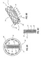
- FIG. 2 is a perspective partial cut away view of a stent sensor device surrounded by a sheath.
- FIG. 3 is a cross-section taken along the line 3 — 3 in FIG. 2 .
- FIG. 4 is an enlarged cross-sectional view through the sensor element of FIG. 3 .
- FIG. 5A is a cross-sectional view through a stent showing one mounting configuration of an embedded sensor in accordance with one embodiment of the present invention.
- FIG. 5B is a cross-sectional view as in FIG. 5A of a stent with an alternate configuration for the embedded sensor.
- FIG. 5C is a cross-sectional view as in FIG. 5A of a stent with an embedded sensor mounted completely on the luminal side of the stent.
- FIG. 6A is a perspective view of an alternate support structure in accordance with the present invention.
- FIG. 6B is a perspective view of a further support structure in accordance with the present invention.
- FIG. 6C is a perspective view of the support structure illustrated in FIG. 6A , provided with an outer fabric sheath.
- FIG. 7A is a side elevational view of the distal end of a catheter-based delivery system for a stent sensor device.
- FIG. 7B is a cross-sectional view of a catheter-based delivery system for a rolled sheet type self-expanding stent with an embedded sensor.
- FIG. 7C is a cross-sectional view of a catheter-based delivery system, which uses a restraining sheath, for a self-expanding stent with an embedded sensor.
- FIG. 7D is a cross-sectional view of a catheter-based delivery system, with a pull-away sheath, for a self-expanding stent with an embedded sensor.
- FIG. 7E is a cross-sectional view of a catheter-based delivery system for a balloon expandable stent with an embedded sensor.
- FIG. 7F is a cross-sectional view of a catheter-based delivery system for a self-expanding stent with an embedded sensor, in which the guidewire lumen passes on either side of the sensor.
- FIG. 8 is a cross-sectional view of the catheter-based delivery system taken along the 8 — 8 line of FIG. 7 A.
- FIG. 9A is a cross-sectional view through a stent showing a transducer across the cross-section of the stent in accordance with the present invention.
- FIG. 9B is a perspective view of an expanded stent with an embedded sensor housing on its abluminal side and a transducer across the cross-section of the stent.
- FIG. 9C is an enlarged cross-sectional view of the transducer of FIG. 9B , taken from the 9 C— 9 C line.
- FIG. 9D is a perspective partial cut away view of a stent sensor device surrounded by a sheath with a transducer partially across the cross-section of the stent.
- FIG. 9E is a perspective view of an expanded stent with an embedded sensor housing on its abluminal side and four perpendicular transducers placed partially across the cross-section of the stent.
- FIG. 10 shows a side elevational view of a sensor and transmitter, with expanded anchoring stents at the proximal end of the sensor, intermediate between the sensor and transmitter, and at the distal end of the transmitter.
- FIG. 11 shows a side elevational view of a sensor and transmitter, with anchoring stents in the compressed state at the proximal end of the sensor, intermediate between the sensor and transmitter, and at the distal end of the transmitter.
- an intraluminal blood glucose sensor is provided on a support structure such as a modified stent of the type implanted following percutaneous transluminal coronary angioplasty (PTCA) for the treatment of atherosclerosis.
- PTCA percutaneous transluminal coronary angioplasty
- Atherosclerosis is the build-up of fatty deposits or plaque on the inner walls of a patient's arteries. These lesions decrease the effective size of the artery lumen and limit blood flow through the artery, prospectively causing a myocardial infarction or heart attack if the lesions occur in coronary arteries that supply oxygenated blood to the heart muscles.
- a guide wire is inserted into the femoral artery and is passed through the aorta into the diseased coronary artery.
- a catheter having a balloon attached to its distal end is advanced along the guide wire to a point where the stenotic lesions limit blood flow through the coronary artery.
- the balloon is then inflated, compressing the lesions radially outward against the wall of the artery and substantially increasing the size of the arterial lumen, to improve blood circulation.
- stents are being used in place of or in addition to PTCA for treatment of atherosclerosis, with the intent of minimizing the need to repeatedly open a stenosed artery.
- stents are generally configured as elongate cylindrical structures that can assume two different states, one having a substantially greater diameter than the other.
- a stent is implanted in a patient's vascular system using an appropriate delivery system. There are two basic types of stents.
- the first type is termed “balloon expandable”, and refers to stents that are expanded radially outward due to the force from an inflated angioplasty balloon, such as the Palmaz-Schatz stent, the Gianturco-Roubin stent, and the Strecker stent.
- the second type is termed “self-expandable”, and refers to and those that are self-expanding, such as the HemobahnTM and SMART StentTM (made of nickel titanium memory alloy), and the Wallstent (made of Elgiloy).
- a stent carried by a delivery catheter is advanced through a guide catheter to a site within the patient's artery.
- a balloon disposed inside the stent is inflated to a pressure ranging from about six to ten atmospheres.
- the force produced by the inflated balloon expands the stent radially outward beyond its elastic limit, stretching the vessel and compressing the lesion to the inner wall of the vessel.
- a self-expanding stent expands due to spring force following its positioning within the artery, after a restraining sheath is retracted from the compressed stent.
- the balloon expandable type is used, the balloon is deflated and removed from inside the stent and the catheter and other delivery apparatus is withdrawn.
- the lumen through the vessel should be substantially increased, improving blood flow.
- a clinical examination and either an angiographic or ultrasonographic morphological procedure is performed to evaluate the success of the procedure in opening the diseased artery or vessel. These tests are typically repeated periodically, e.g., at six-month intervals, since restenosis of the artery may occur.
- the stent may be modified from those intended for supporting a treatment site following angioplasty, in view of the preferred placement in a healthy section of the vessel as is discussed in greater detail below.
- the wall of the stent may be modified to support the sensor, as is also discussed in greater detail below.
- a stent provides a useful platform for a variety of additional reasons. For example, it is impractical to pass an electronic conductor through the wall of an artery or vessel to monitor the condition of an implanted sensor for long periods of time. Also, any active glucose sensor must be energized with electrical power. Again, it is not practical to supply power to such a sensor through any conductor that perforates the vessel wall or that passes outside the patient's body.
- endoluminal implant encompasses stent-grafts, which are also sometime referred to as “covered stents.”
- a stent-graft is a combination of one or more stents and a synthetic graft that is typically implanted at a desired point in a vessel using an endoscopic approach. The stent is attached either to the ends or throughout the body of the synthetic graft, and is used to hold the graft in position. Sometimes, hooks are provided on the stent to ensure that the graft remains in the desired position within the vessel.
- Endoluminal implants are used in other body passages in addition to blood vessels. For example, they are sometimes used to maintain an open lumen through the urethra, or through the cervix. A stent placed adjacent to an enlarged prostate gland can prevent the prostate from blocking the flow of urine through the urinary tract. Tracheal and esophageal implants are further examples of endoluminal implants. In these and other uses of an endoluminal implant, provision for monitoring parameters related to the status of flow and other conditions in the patient's body would be desirable. Information provided by monitoring such parameters can enable more effective medical treatment of a patient.
- IVUS intravascular ultrasonography
- Another important factor, and related, is that the stents must be placed in close apposition to the vessel wall, so that the only flow obstructions are at the luminal surface of the stent struts. They later demonstrated that by using non-compliant balloons at high pressure (18 atm), that even the final assessment using IVUS is not required; an important consideration for centers lacking such equipment. Thus, it is very important to minimize flow disturbances which may be created by stent implantation. This is more critical in the smaller coronary arteries, which range from about 2.5-4 mm in diameter, than it is in other, larger arteries, where small amount of mural thrombus will have less effect on the volumetric flowrate.
- a layer of fibrin clot deposits on the luminal surface of the implanted stent. After 3-4 weeks, the fibrin layer is typically remodeled into fibro-collagenous tissue, with a layer of endothelial cells present on the flow surface.
- a relatively thick layer of fibro-collagenous tissue forms on the surface of an endovascular sensor, it may experience the same loss of signal that has been reported for subcutaneously implanted sensors. That is, a modified type of “foreign-body response” may occur, and glucose may not be able to freely and rapidly diffuse to the sensor.
- the stent-sensor combination of the present invention should be placed in a relatively healthy portion of the artery. If it is placed in a stenotic or calcified area, it may be difficult for the device to expand completely, so the device may be more narrowed than is intended, resulting in thrombotic fouling of the sensor, or distal embolization may occur. If the device is placed in an aneursymal vessel, it may expand more than intended, and again, fail to function as designed.
- stent-graft-sensor combination might be more suitable than a stent-sensor combination without the graft material. Further considerations will become apparent from the illustrated embodiments of the present invention which are discussed below.
- FIG. 1A shows a perspective view of an expanded implantable sensor device 10 having a proximal end 12 , a distal end 5 and a central lumen 16 extending therethrough.
- the expanded implantable sensor device 10 is comprised of a stent 14 and a sensor 20 .
- the stent 14 illustrated in FIG. 1A resembles a Palmaz-Schatz stent, it is understood that any of a wide variety of stent configurations can be utilized such as those identified below.
- the stent 14 comprises a tubular sidewall 18 , which may be compressed to a relatively small diameter for delivery using a catheter, and which may be expandable to the approximate diameter of the vessel or to a diameter approximately 5-25% greater than the diameter of the vessel lumen.
- a self-expanding variety of stent or stent-graft such as the S.M.A.R.T. Stent (Cordis Corp., Miami, Fla.) or Hemobahn (W.L. Gore & Associates, Flagstaff, Ariz.) is preferred, since the presence of the sensor body may impede proper expansion of the stent platform using a balloon.
- the sensor housing can preferably be attached to the stent by use of adhesives, by tying (suturing) the two components together, or by use of thermal bonding, soldering, welding or brazing, or mechanical interfit or the like.
- the sensor and sensor housing should be attached to the stent along a single row of stent struts, so that the struts may fully expand without needing to stretch the sensor housing, or being constrained by the sensor housing.
- the expanded inside diameter of the device may range from 3 to 20 mm, and the length of the device may range from 1 to 30 cm.
- the radially inwardly facing or radially outwardly facing sidewall of the stent may also be covered by a sheath as is known in the art. The sheath can be bonded to the surface of the stent so that the sheath remains in close apposition to the vessel wall.
- a sensor 20 contains the sensing circuitry within its housing.
- the attachment between the sensor 20 and the stent can take any of a variety of forms as will be apparent to those of skill in the art in view of the disclosure herein.
- adjacent axially extending parallel struts of the stent design illustrated in FIG. 1A spread circumferentially apart upon expansion.
- the sensor 20 should be mounted to only colinear axial struts along the length of the stent unless the mounting is designed to accommodate circumferential separation of parallel struts.
- the stent 20 may be positioned in an aperture which is cut in the sidewall of the stent 14 , and attached to the strut portions adjacent to the edge of the aperture. Attachment may be accomplished in any of a variety of ways, such as by the use of adhesives, thermal bonding, soldering, welding or brazing, or mechanical interfit, depending upon the construction materials of the stent 14 and the sensor 20 .
- the sensor 20 may be solvent bonded, adhesively bonded or otherwise attached to an expandable tubular sleeve which is positioned concentrically about the stent 14 .
- Other attachment configurations can be devised by those of skill in the art in view of the disclosure herein.
- all or a portion of the sensor 20 is positioned on the radially outwardly facing surface of the tubular sidewall 18 .
- Positioning the sensor 20 on the radially outwardly facing surface may advantageously optimize blood flow through the central lumen 16 and/or reduce turbulence in the central lumen 16 .
- the sensor 20 may be positioned on the radially inwardly facing surface (sometimes referred to herein as the luminal surface) of the stent.
- the stent struts or other elements which make up the sidewall 18 may be removed or modified at the portion of the sidewall corresponding to the sensor 20 such that the sensor 20 may be mounted within the resulting opening in the sidewall.
- the implantable sensor device 10 in accordance with the present invention, is preferably positioned within a healthy section of the vessel, the radial strength normally required for a stent in a post-angioplasty application is unnecessary.
- the present inventor believes that any reduction in radial support which may result from reasonably dimensioned apertures or other modifications to the sidewall to attach sensor 20 will not adversely affect the role of the stent as a sensor support structure in the context of the present invention. Additional details concerning the position of the sensor 20 with respect to the tubular wall 18 will be discussed below in connection with FIGS. 5A-5C .
- the sensor circuitry 22 includes a sensing circuit 24 , which is connected to a signal processing circuit 26 , which is connected to a power source 28 , a radio transmitter 30 , and an antenna (not shown) to transmit signals about the glucose concentration to a remote device.
- the antenna (not shown) may be a thin wire wound around the stent 10 .
- the power source 28 may be inductively coupled to an external device, or it may be a thin film rechargeable battery, as in Bates, J. B. et al., “ Thin Film Rechargeable Lithium Batteries for Implantable Devices ”, ASAIO J., 1997 43:M644-M647, which is incorporated herein by reference.
- the sensing circuit 24 is in electrical communication with a sensing surface (not illustrated in FIG. 1A ) for sensing the analyte of interest in the fluid stream.
- the sensor surface is preferably positioned radially inwardly from the radially inwardly facing surface of the tubular sidewall 18 , to improve the useful life of the device as is discussed elsewhere herein.
- the sensor surface is displaced radially inwardly such as by a radially inwardly extending portion of the housing or other support (not illustrated) to achieve the desired radial position of the sensor surface.
- the sensor 20 may be positioned directly on a radially inwardly-most extending portion of the sensor 20 as is discussed elsewhere herein.
- the sensor surface is preferably covered by a semi-permeable membrane (not shown), which contacts passing blood when the stent 14 is placed in a blood vessel.
- the permeability of the membrane is selected to allow blood glucose, or the analyte of interest to freely contact the sensor, while restricting the passage of other blood components.
- the semi-permeable membrane may comprise ePTFE, Dacron®, polyurethane, silicone rubber, poly(lactide-co-glycolide) (PLGA), poly(caprolactone) (PCL), poly(ethylene glycol) (PEG), collagen, polypropylene, cellulose acetate, poly(vinylidene fluoride) (PVDF), nafion or other biocompatible material.
- These membrane materials may also be used for the tubular sheath which can be used to surround either the luminal or abluminal surfaces of the stent.
- the membrane of the sheath may be bonded to the stent by adhesives or by tying (suturing) the two components together or by use of thermal bonding, soldering, welding or brazing, or mechanical interfit.
- the pore size of the lumenal membrane may be large enough to allow cells to come through if it covers the sensor surface, but the sensor membrane should have a pore size (MW cutoff of about 1000) which will allow glucose to pass, while restricting the passage of larger molecules.
- the entire tube surface does not have to be composed of the same membrane material.
- the part of the device near the sensing element can be composed of a different material or have a different porosity than the material in the rest of the device.
- a remote circuit 32 is equipped with an antenna 34 and a signal processing unit 36 , which converts the electronic signal from the embedded sensor into a concentration level or other indicium of the analyte.
- a signal processing unit 36 which converts the electronic signal from the embedded sensor into a concentration level or other indicium of the analyte.
- an alarm circuit 38 and a display 40 are also provided.
- Information regarding the level of the analyte of interest can be displayed on the display 40 such as a monitor 42 .
- the signal processing unit 36 may be provided with a lookup table or other baseline of normal or expected values for the analyte of interest. If the concentration of the analyte goes outside of the prescribed range, or if an electronic failure is detected, a warning audible, visible, or tactile signal is preferably produced from the alarm system 38 .
- a transmitter 44 may also be included in the remote circuitry 32 in order to transmit data about the level of the analyte of interest to an implantable infusion pump, or the
- the remote circuitry 32 can be provided in any of a variety of physical forms, depending upon the intended use of the device.
- the remote circuitry 32 can be provided in a desktop or bedside housing and coupled directly to a display 40 such as a monitor 42 .
- ambulatory patient devices may be provided by deleting a permanent coupling to the monitor 42 and packaging the remaining components of remote circuit 32 in a wearable form, such as a compact self-contained unit adapted for attachment to the wearer's clothing or including straps so that it can be strapped to the patient's body.
- the signal processing unit 36 includes sufficient memory to record the glucose values over a predetermined period of time.
- the patient can couple the wearable device to an external monitor 42 or other electronics periodically, such as one or more times per day.
- Analyte data may thereafter be displayed in readable form, such as on a monitor 42 in table form or in graph form with a time unit on the X axis and a glucose value or derivative data on the Y axis.
- the wearable unit may additionally be provided with a data export coupling, such as a telephone connector, for connecting the signal processing unit 36 via internal or external modem into the telephone system. In this manner, the patient can transmit condensed analyte data to the healthcare provider for further monitoring and/or analysis.
- the wearable unit may additionally be provided with one or more manual data inputting elements ranging from a simple push button to a keypad, to allow manual data entry relating to significant dietary or other events. For example, meal times, significant fluid intake, manual insulin injection or other administration, or any of a variety of other significant events can be marked in the data, so that the patient or reviewing medical personnel can correlate the event with the blood glucose data.
- an implantable or externally wearable infusion pump 46 may be controlled by the remote circuit 32 via a receiver 48 in the pump, or may be manually controlled using sensor information only as a guideline.
- the infusion pump 46 may be refilled through an appropriately designed port 50 such as a pierceable septum using a hypodermic needle or other appropriate delivery system.
- the infusion pump 46 may be implantable, as described by Irsigler et al., (“ Controlled Drug Delivery in the Treatment of Diabetes Mellitus ”, Crit. Rev. Ther. Drug Carrier Syst. 1(3): 189-280(1985)), which is incorporated herein by reference.
- External insulin infusion pumps are currently marketed by suppliers like Medtronic, or Siemens. However, these pumps are not designed to receive a continuous signal from an implanted sensor, but instead are pre-programmed to approximate the patient's baseline insulin requirements. Such pumps can be modified with an with appropriate circuitry to receive and respond to output from the glucose sensor by those of skill in the art in view of the disclosure herein.
- the sensor 10 comprises a cylindrical stent wall 18 surrounded by a sheath 52 .
- An antenna (not shown) may be wound around the body of the sensor 10 and connected to the power source or the transmitter.
- All relevant electronics are schematically illustrated as in electronics housing 54 which is electrically coupled to a sensor 56 by one or more conductors 57 . All such junctions of dissimilar metals are coated with polymers which are impermeable to bodily fluids in order to reduce galvanic corrosion.
- the analyte sensing element 56 is covered with a membrane 62 ( FIG. 4 ) which is permeable to the analyte of interest.
- the analyte sensing element 56 extends radially inwardly within the sensor 10 where blood flow conditions are optimal.
- the illustrated analyte sensing element 56 contains an enzyme gel layer 64 , which is placed adjacent to the outer permeable membrane 62 .
- the analyte diffuses through the membrane 62 to the gel enzyme layer 64 .
- the reaction between the analyte and the enzyme occur in the gel enzyme layer 64 .
- the reaction products then pass through an inner membrane 66 and react at the surface of a noble metal electrode 68 , producing a current.
- An appropriate potential is applied to the electrode 68 from the power source contained in electronics housing 54 resulting in a signal, which is sent to the signal processing unit.
- the signal is then passed through the transmitter which transmits the information regarding the analyte of interest to an external monitor and/or implantable pump as has been discussed.
- the power source, the signal processing unit, and the transmitter are completely encapsulated in a housing 55 which is impermeable to biological fluids.
- the same housing 55 or a separate housing 70 also encapsulate the analyte sensor except for the membrane 62 .
- the sensor(s) to be incorporated into the device may be either electrochemical, piezoelectric, thermoelectric, acoustic, or optical. As known to those skilled in the art, there is a significant body of literature regarding the development of electrochemical glucose sensors. These generally incorporate an enzyme, which selectively reacts with glucose.
- Electrochemical biosensors may be categorized as amperometric, conductometric, or potentiometric.
- Amperometric measurements are based on the oxidation or reduction or electrochemically active substances involved in the oxidation of glucose via glucose oxidase.
- Another method is measurement of changes in local pH due to the gluconic acid producing using a potentiometric sensor, usually a coated-wire pH selective electrode and/or ion-selective field effect transistor (ISFET).
- ISFET ion-selective field effect transistor
- Conductometric sensors are based on the principle of electrical resistance changes during the reaction.
- Potentiometric and conductometric sensors are currently limited due to the presence of numerous interfering chemicals in the environment.
- the main disadvantage of these sensors is their low sensitivity.
- the response of the potentiometric sensor depends on logarithmic changes in analyte concentration.
- ISFET ion selective field effect transistors
- Amperometric sensors respond linearly to the analyte concentration. If the limiting processes in signal generation are the enzymatic reactions, the dependence of the signal on glucose concentration is non-linear according to Michaelis-Menton kinetics. When the sensor operates in a glucose diffusion-limited mode, the signal is linearly proportional to the analyte concentration. Amperometric sensors are further subdivided into three classes:
- Oxygen-electrode based sensors
- the Clark oxygen electrode employs a platinum cathode held at a potential of approximately ( ⁇ )0.6 V versus the saturated calomel electrode (S.C.E.), a sufficiently negative potential to reduce oxygen as follows: O 2 +4H + +4 e ⁇ ⁇ 2H 2 O Because the species being measured in this reaction is a gas, interference from other species in the biological fluid is negligible. However, the signal is determined from reduction of the initial current, making glucose determinations at low concentrations difficult. Further, the system requires the use of a second electrode without any glucose oxidase, to determine the local oxygen tension for the glucose measurement. In addition, it is necessary to insure that there is excess oxygen in the catalytic layer so that the reaction rate is limited by the glucose.
- the ratio of blood glucose to oxygen can be as high as 10 to 1 in arterial blood, and 100 to 1 in venous blood. (Jaffari 1995) An oxygen electrode sensor has been described by Armour et al. (1990), which was implanted in the superior vena cava of six dogs for up to 15 weeks, with good agreement with standard in vitro assays.
- Hydrogen Peroxide based sensors measure hydrogen peroxide production based on the oxidation of glucose at potentials above +600 mV vs. SCE. This signal is directly related to the concentration of glucose in the sample. H 2 O 2 ⁇ O 2 +2H++2 e ⁇
- Bindra et al. (Bindra, D. S. et al., “ Design and in vitro studies of a needle type glucose sensor for subcutaneous monitoring ,” Anal. Chem., 63: 1692-6 (1991)) reported glucose detection for up to 10 days in rats with a needle-type sensor, which consisted of GOD immobilized onto cellulose acetate as an inner membrane, and polyurethane as an outer membrane. Moussy et al. (Moussy, F. et al., “ Performance of subcutaneously implanted needle - type glucose sensors employing a novel trilayer coating ,” Anal.
- Chem., 65: 2072-7 (1993) used a needle type sensor with a trilayer coating. Nafion was used as an outer membrane, and poly (o-phenylenediamine) as an inner membrane to reduce interference from small electroactive species. GOD was immobilized between these two layers. As with the oxygen electrodes, the reaction must be limited by glucose, not oxygen.
- Amperometric sensors with direct electron transfer are independent of the oxygen concentration and involve direct oxidation of glucose by GOD at an electrode constructed from conducting organic salts (charge-transfer organic complexes with electron conductivity). Sensors based on this principle have been tested in vivo in rats, but little is presently known about the biocompatibility of such materials.
- an amperometric electrode is used.
- the characteristics of such an electrode such as one available from Minimed, Inc. (Sylmar, Calif.), is related to the production of hydrogen peroxide in the conversion of glucose to gluconic acid by glucose oxidase.
- the noble metal electrode 68 may be connected to any of a variety of RF transceivers.
- the system may be powered by, and signal transmission occurs via an inductive link. This requires an inductive coil (not shown) to be placed both inside the external receiver and an inductive coil (not shown) within the implantable sensor device 10 .
- transceiver to be used in the Ventak Mini IV automatic implantable cardioverter defibrillator (Guidant Corp, Santa Clara, Calif.).
- the transceiver coil in the preferred embodiment is specifically adapted for use with a stent platform.
- the size of the coil, in addition to the number of turns around the implant limits the power and signal transmission distance between the implant and the external receiver/power supply.
- the coil is wound around the outside of the implantable sensor device 10 .
- the transceiver coil is made from an electrically conductive material, and is coated to prevent corrosion.
- the coil may be aligned with and bonded to the struts of the implantable sensor device 10 , in order to minimize any impact on expansion of the implantable sensor device 10 .
- the struts of the implantable sensor device 10 themselves may serve as the antenna coil.
- the internal and external coils should be aligned so that their major axes are parallel.
- the external receiver coil should contain a ferrite core to optimize power and signal transmission.
- the external receiver and power supply should be designed so that it can be worn on the patient's body, and can be oriented to maximize the signal from the implanted sensor. This can be done by custom-placed foam padding to orient the external receiver and power supply.
- the sensor device may be held in place within the vessel by any of a variety of anchoring systems other than a graft or stent.
- anchoring systems other than a graft or stent.
- any of a variety of anchoring structures may be provided with hooks or barbs to engage the vessel wall.
- semicircular cages or struts may be used, which only extend through a partial circumference of the vessel.
- FIG. 6A shows struts 74 that can be positioned securely against a blood vessel.
- An axially extending strut 76 connects the circumferential struts 74 , and also could support a sensor.
- the support 72 can be manufactured in a variety of ways, such as by injection molding a suitable polymeric material or by laser cutting from stainless steel, Nitinol or other tube stock.
- FIG. 6B shows alternate struts 74 that can be secured against the vessel wall. Again, connecting struts 74 is one or more connecting struts 76 .
- FIG. 6C shows a modification of the device shown in FIG. 6A , where the support 72 is provided with a sheath 180 .
- a catheter-based delivery system In order to implant an implantable sensor device within the vasculature of the patient, a catheter-based delivery system is used. All implantable sensor devices are formed to include a central lumen with a diameter in the reduced profile sufficient to allow passage of a guide wire and a catheter tip through it. The implantable sensor device is mounted onto a catheter tip, and then collapsed to as small a diameter as possible. The implantable sensor device may be deployed by removal of a deployment sheath, or other methods, which may be preferred for the specific type of stent platform being employed. These methods are well known in the art. After the implantable sensor device is deployed, the catheter and guidewire are removed from the (now enlarged) central lumen in the implantable sensor device. The implantable sensor device is placed such that neither the catheter nor the guidewire adversely affects the electronic circuitry.
- the implantable sensor device is implanted in a relatively large artery or vein (>5 mm) in order to minimize the risk that the implant may occlude the artery.
- a healthy artery or vein should be chosen, so that the device can open completely, and so that the flow patterns are normal.
- the sensor or sensing element i.e., the transducer
- the sensor or sensing element can be placed directly across the path of the flowing blood, on a surface with low cross-sectional area, such as a wire with a diameter of 0.003′′ to 0.025′′, or a ribbon, oriented with its narrow edge facing upstream.
- the transducer or sensor can be placed on either the proximal, distal, or lateral faces of the wire or ribbon.
- FIG. 9A shows a cross-sectional view through a stent 14 , which includes a sensing element 120 consisting of a wire-like noble electrode 68 , which in turn is covered by a gel-enzyme layer 64 and finally by an analyte-permeable membrane 62 .
- the outside of the analyte-permeable membrane 62 is bound to a wire-like structure made of a shape memory material 110 such as nitinol, which is either part of or is bonded to the stent 14 .
- the shape memory material allows the electrode 68 and sensing element 120 to be positioned directly across the lumen of the vessel, as described above.
- the electrode 68 is connected to the signal processing unit (not shown) through a conductor (not shown).
- the remainder of the implantable sensor 10 including the power source, signal processing unit, transmitter, and stent, are positioned to be flush against the vessel wall.
- FIG. 9B shows an implantable sensor device 10 with a sensing element 130 across the cross-section of the stent 14 , with sensor circuitry 22 .
- FIG. 9C shows an enlarged cross-sectional view of the sensing element 130 of FIG. 9B , taken along the 9 C— 9 C line.
- the sensing element 130 consists of a wire-like noble electrode 68 , which in turn is covered by a gel-enzyme layer 64 and finally by an analyte-permeable membrane 62 .
- the outside of the analyte-permeable membrane 62 is bound to a wire-like structure made of a shape memory material 110 such as nitinol, which is bonded to the stent 14 on both ends.
- the sensing element 130 is connected to the sensing circuit 24 through a conductor (not shown).
- FIG. 9D illustrates a transducer 140 , consisting of a wire-like noble electrode 68 , which in turn is covered by a gel-enzyme layer 64 and finally by an analyte-permeable membrane 62 , which is bound to a wire-like structure made of a shape memory material 110 such as nitinol, which is bonded to the stent 14 .
- the sensing element 140 is connected to the sensing circuit 24 through a conductor (not shown).
- FIG. 9E shows another configuration with quadruple sensing elements 150 , each at right angles to each other, attached to stent 14 , with sensor circuitry 22 .
- the sensing elements 150 are connected to the sensing circuit 24 through a conductor (not shown).
- a conductor not shown.
- multiple transducers could be positioned to form a wire mesh, provided the mesh size is sufficiently large to permit blood flow without significant thrombo-embolization.
- a very small sensor surface area impedes blood flow, compared to the blood vessel's cross-sectional area.
- a deployment catheter 80 which may be utilized to deploy a self-expandable stent type sensor support in accordance with the present invention.
- the catheter 80 comprises a proximal end 82 , a distal end 84 and an elongate flexible tubular body 86 extending therebetween.
- the length of the tubular body 86 will vary depending upon the intended access point and deployment site for the stent sensor. For example, lengths in the area of about 120 cm to about 140 cm are typical for use in a coronary artery implantation by way of a femoral artery percutaneous puncture site. Other lengths for different access sites and deployment sites will be apparent to those of skill in the art in view of the disclosure herein.
- the tubular body 86 may be manufactured in accordance with any of a variety of known techniques, such as by extrusion of appropriate biocompatible polymeric materials. Known materials which are commonly used for this application include high density polyethylene, polytetrofluroethylene, nylons, and a variety of others known in the art. Alternatively, at least a portion or all of the lengths of the tubular body 86 may comprise a spring coil, solid wall hypodermic needle tubing, or braided reinforced wall, depending upon the functional requirements of the catheter.
- the tubular body 86 will be provided with an approximately circular cross-sectional configuration having an external diameter within the range of from about 0.025 inches to about 0.065 inches.
- the tubular body 86 comprises a multilumen extrusion having an external diameter of about 0.042 inches (3.2 f) throughout substantially all of its length.
- the tubular body 86 can have diameters as large as 12 Fr or higher.
- the proximal end 82 is provided with a manifold 88 , having a variety of access ports depending upon the desired functionality of the catheter 80 .
- the manifold 88 is provided with a guidewire port 90 and a deployment wire port 94 .
- Manifold 88 may be manufactured by injection molding, or other techniques known in the art.
- the distal end 84 of deployment catheter 80 is provided with a collapsed support structure 96 having a sensor housing 20 thereon in accordance with the present invention.
- the support structure 96 is illustrated in its collapsed, low profile configuration, such as for transluminal advancement towards a placement site.
- the tubular body 86 may be provided with an annular recess 98 near the distal end 84 , for receiving the support structure 96 .
- the tubular body 86 may be provided with a recess for receiving the sensor housing 20 , thereby reducing the collapsed profile of the loaded catheter 80 .
- the support structure 96 may be constrained in its reduced crossing profile configuration in any of a variety of ways as has been discussed.
- the support structure 96 is restrained in its collapsed configuration by a deployment wire 94 .
- Deployment wire 94 extends throughout the length of the tubular body 86 through a deployment wire lumen 108 , such that a proximal end of the deployment wire 94 may be proximally retracted by the clinician.
- the distal end of the deployment wire 100 exits the tubular body 86 at a deployment wire port 100 , and loops the support structure 96 in one or more loops or slip knots 102 to restrain the support structure 96 in its collapsed configuration.
- Loops or slip knots 102 are configured such that proximal retraction on deployment wire 94 causes the loops or slip knots 102 to become untied or otherwise disengaged, thereby releasing the support structure 96 so that it expands radially outwardly from its low profile introduction configuration to its radially enlarged implanted configuration.
- the catheter 80 is preferably introduced over a guidewire as is known in the art.
- a distal guidewire opening 104 is in communication with the proximal guidewire port 90 by a guidewire lumen 106 extending therebetween.
- the self-expanding implantable sensor device 96 can be deployed from a tubular restraining sheath 108 by pushing a rod 110 optionally attached to a disk 112 , until the implantable sensor device 96 is pushed clear of the restraining sheath 108 .
- a rod 110 optionally attached to a disk 112
- An example of such a technique is described in U.S. Pat. No. 5,411,551 to Winston et al. (issued May 2, 1995).
- FIG. 7C another deployment method for a self-expanding implantable sensor device 96 is shown.
- the implantable sensor device 96 is restrained onto the shaft of the catheter 114 by a sheath 116 and a tether line 118 .
- the sheath 116 unfolds when the tether line 118 is pulled, allowing the implantable sensor device 96 to deploy.
- FIG. 7D another deployment method for a self-expanding implantable sensor device 96 is shown.
- the implantable sensor device 96 is restrained onto the shaft of the catheter 120 by two or three or more restraining prongs 122 , 124 .
- the restraining prongs 122 , 124 are retracted when one or more deployment wires 126 are pulled, allowing the implantable sensor device 96 to expand.
- An example of this can be shown in U.S. Pat. No. 6,024,763 to Lenker et al. (issued Feb. 15, 2000), which is herein incorporated by reference.
- the rails are only designed to minimize frictional forces between a deployment sheath and the device.
- prongs can be used to minimize the delivery profile of the device. Since the sensor and electronic circuitry may not collapse to a profile as small or as circular as a stent or stent-graft, it may be more appropriate to position the electronic components on one side of the catheter, and layer the collapsed stent on the opposite side of the catheter. This could be achieved by use of delivery prongs, as described.
- the implantable sensor device 96 may be deployed by use of a suitable balloon catheter 128 if a balloon expandable stent platform is used.
- the balloon 130 is inflated at elevated pressures of 2 to 20 atmospheres, and after the implantable sensor device 96 is fully expanded, the balloon 130 is deflated and then the balloon catheter 128 is withdrawn.
- Use of such balloon catheters is well known in the art.
- the self-expanding implantable sensor device 96 can be deployed from a tubular restraining sheath 108 by proximally retracting the sheath 108 with respect to a push rod 110 optionally attached to a disk 112 , until the implantable sensor device 96 is exposed clear of the restraining sheath 108 .
- the constrained stent support structures 14 at either end of the sensor 96 may be held in place by a release mechanism, 214 , which may be a simple knob or hook.
- the atraumatic catheter tip 216 Prior to deployment, the atraumatic catheter tip 216 is in direct apposition to tubular restraining sheath 108 .
- a small shaft 222 connects the push rod 110 or disk 112 to the catheter tip 216 .
- a guidewire 218 passes through guidewire lumen 220 , which may be located eccentrically with respect to the axis of the catheter.
- guidewire lumen 220 An example of a similar technique is described in U.S. Pat. No. 5,411,551 to Winston et al. (issued May 2, 1995) which is incorporated herein by reference.
- the guidewire passes directly through the center of the catheter, whereas in the present disclosure the guidewire passes eccentrically through the delivery catheter. Allowing the guidewire to pass eccentrically through the catheter allows the sensor to be hermetically sealed, and permits a less complex sensor geometry. Additionally, the eccentric guidewire lumen provides a smaller delivery profile for the sensor and its delivery system.
- glucose diffuses through the semi-permeable membrane 62 .
- the housing design should keep the blood shear rate at the apex of the housing sufficiently high that there is minimal thrombosis on this surface and any formed thrombus will be of minimal thickness.
- diffusion of glucose through the semi-permeable membrane 62 should be the rate-limiting step, and surface of the device should not become covered in a fibrous capsule, as in the case of subcutaneous sensors.
- the glucose reacts with the glucose oxidase to produce hydrogen peroxide, which further reacts to produce an amperometric signal.
- the amperometric signal is converted by an appropriately designed electronic circuit so that it may be transmitted using the RF transceiver.
- the surface of the sensor 20 should be placed on the luminal side of the stent.
- the electronic components of the sensor should be encapsulated in a conformal coating such as a fluoropolymer or a polyamide, and injection-molded or dip-coated in a silicon rubber, polyurethane, or other biocompatible housing material.
- the sensor housing should be given a streamlined shape, with gradually sloped transitions at both its proximal and distal ends, in order to minimize flow disturbances.
- the housing should be as wide or wider at its base than at its apex.
- the apex of the housing should not protrude higher than 5-50% of the diameter of the fully deployed device.
- the glucose permeable membrane 62 should be placed at the apex of the housing, should not be encapsulated in the housing material, and should face the bloodstream.
- the glucose permeable membrane 62 should occupy the majority of the area of the housing apex.
- the stent may be placed on either the luminal or abluminal surface of a graft material. If the graft is place on the abluminal surface of the stent, the sensor should be placed on the luminal surface of the graft.
- the graft material is preferably a fluoropolymer, such as ePTFE.
- the housing is placed on the luminal surface of the graft, it is bonded by partially dissolving the housing material thermally or using an appropriate solvent so that the housing becomes physically interpenetrated with the graft or with an appropriate adhesive, such as melt-processed poly(tetrafluoroethylene-co-hexafluoropropylene) (FEP).
- FEP melt-processed poly(tetrafluoroethylene-co-hexafluoropropylene)
- the height of the sensor is estimated to be 2 to 3 times the thickness of a stent strut, based on some observations of a limited number of stent designs (Virmani, 1999). This estimate represents the approximate thickness of the fibrous tissue layer above the stent surface.
- the sensor height above the stent luminal surface should be 1-2 times the thickness of a stent strut.
- the strut thickness varies with design, but is roughly 0.005′′ to 0.010′′ (0.13 to 0.26 mm).
- the housing should protrude about 0.2 to 0.5 mm above the stent luminal surface.
- This table also provides insights into the intrusion of the sensor as a percentage of post-deployment vessel diameter.
- a native vessel with greater than 50% diameter stenosis is clinically defined to be a restenotic vessel, and typically requires re-intervention It is estimated that the sensor should not obstruct more than about 25% of the vessel diameter.
- the percent area loss of a vessel, along with a sensor height, cab be examined and examples are tabulated below:
- the sensor height can range from about 0.3 to 2.5 mm in height above the stent luminal surface.
- flow measurements in piping systems are commonly obtained from the pressure drop across a restriction, such as a Venturi meter.
- the restriction in area is about 43.8%, and the velocity within the restriction is about 178% of the upstream velocity, and for an approximately 5% restriction in diameter, the velocity within the restriction is approximately 111% of the upstream velocity.
- the senor may be flush mounted against the wall of the vessel, with a flow impedance device mounted at the same axial position within the vessel, in order to increase the velocity within the sensor/impedance device to about 125-200% of the proximal flow velocity.
- the location where the estimate of the proximal flow velocity is approximately 200% is preferred. This would allow for the possibility of flush mounted sensors.
- the sensor Prior to implantation, the sensor may be checked for a linear response to glucose concentration. This may be done in the operating theater using sterile technique immediately prior to implantation, or may be done in a batch-wise manner during the manufacturing process. Following implantation, the sensor may then be calibrated by comparison of the output signal with an accepted standard. Typically, this may be done by comparing the signal with the value obtained from a laboratory glucose sensor, such as made by Yellow Springs Instruments (Yellow Springs, Ohio).
- the calibration curve should be stable over time and for wide range of glucose values. For example, the slope of the calibration curve should be sufficiently stable to give an error of less than ten percent. Weekly calibrations should be sufficient to insure stable and accurate readings, however calibration can be performed as frequently as required.
- An audible, visible or tactile alarm may sound, so that the patient or physician may check the sensor with a home glucose monitoring kit (e.g., One Touch, LifeScan, Johnson & Johnson), and then take appropriate action such as administration of insulin or glucose.
- a home glucose monitoring kit e.g., One Touch, LifeScan, Johnson & Johnson
- the signal may be transmitted directly to an implantable insulin pump, which may administer insulin directly without requiring a response by the patient.
- FIGS. 5A-C show various embodiments in which the sensor and transmitter are on either the luminal or abluminal surface of the stent.
- an implanted sensor 20 is shown in a transverse cross-sectional view through the vessel.
- the struts 60 of the implantable sensor device may be surrounded by an inner tubular sheath (not illustrated for simplicity), which would contact the blood vessel wall when deployed.
- the sensor housing 20 sits between a pair of struts 60 .
- the membrane 62 is exposed to the blood flow.
- the analyte sensor 56 will normally have a larger cross-sectional area than the stent struts 60 .
- the outer sheath allows for enhanced uniform radial expansion (beyond that of self-expanding struts), especially if the sheath is bonded to each of the struts 60 of the stent, and is bonded through the length of the stent, not just at the ends. This would link each of the struts 60 to its neighbors, preventing uneven expansion. It would also be advantageous to make the sheath out of a material which could be stretched slightly to obtain its final diameter, so that irregularities in the flow surface are minimized, except in the region of the sensor.
- the stent struts 60 can be embedded more deeply into the vessel wall than the sensor housing 20 . If the struts 60 were positioned between the flowing blood and the sensor surface, they would cause flow stagnation, and therefore thrombosis on the membrane 62 of the sensor. If the sensor is placed instead on the luminal surface of the stent, the sensor will again be embedded less deeply in the vessel wall, although without struts 60 on its luminal surface, there will be minimal hemostasis and thrombus formation on the transducer surface.
- the stent struts could be placed either between the stent struts and the inner sheath, or on the luminal surface of the inner sheath. In both cases, a semi-permeable membrane might still be necessary to insure that only the analyte of interest reaches the surface of the sensor. In either case, the sensor should be designed with a streamlined profile at both its proximal and distal ends, to minimize regions of hemostasis.
- the stent and its associated circuitry are connected between two or more stent segments, with or without the presence of a stent or supporting member at the location of the sensor.
- This provides a number of advantages, including a decrease in the delivery profile, and an increase in flexibility. This allows easier access to sites with tortuous vascular anatomy, but will still allow the sensor to maintain its same relative position in the blood vessel.
- FIG. 10 shows a side elevational view of a sensor 20 , a sensing circuit 24 and signal processing unit 26 , a power source 28 and a radio-transmitter 30 , with expanded anchoring stents 14 at the proximal end 200 of the sensor 20 , intermediate between the sensor 20 and the sensing circuit 24 and signal processing circuits 26 , also intermediate between the sensing circuit 24 and signal processing circuits 26 and the power source 28 and radio-transmitter 30 , and at the distal end 210 of the power source 28 and radio-transmitter 30 .
- Each segment of the implantable sensor device is connected to its neighboring segment by the use of electrical connectors 57 , with strain relief elements 226 .
- the electrical connectors 57 are hermetically sealed.
- the electrical connectors 57 are of sufficient length, and have redundancies so that they can connect the various segments allowing flexibility of positioning between each segment of the implantable sensor while minimizing the strain imparted on the connectors. It is important to note that the relative position of each of these components between the anchoring stents is somewhat arbitrary. The device could be designed with these components in any order, and still function equally well, as will be apparent to those skilled in the art.
- FIG. 11 shows a side elevational view of a sensor 20 , a sensing circuit 24 and signal processing unit 26 , a power source 28 and a radio-transmitter 30 , with anchoring stents 14 in the compressed state such as within a tubular deployment catheter at the proximal end 200 of the sensor 20 , intermediate between the sensor 20 and the sensing circuit 24 and signal processing circuits 26 , also intermediate between the sensing circuit 24 and signal processing circuits 26 and the power source 28 and radio-transmitter 30 , and at the distal end 210 of the power source 28 and radio-transmitter 30 .
- the advantages of this segmented embodiment of the invention are that the overall delivery profile of the device is reduced, and the device becomes more flexible for delivery through tortuous vessels.
- the present invention provides at least one electrical component, having at least a first support on a proximal end and a second support on a distal end, for supporting the component in a body lumen.
- the electrical circuitry may desirably be divided into at least two or three discrete physical components spaced axially apart and in electrical communication with each other to minimize the implanted profile and enhance deliverability.
- Each of the components may be provided with a proximal and a distal support, as illustrated in FIGS. 10 and 11 .
- the two or three or four or more supports may be connected together independently of the intervening electrical component, or may be connected only through the housing of the intervening electrical component.
- the supports may comprise any of a variety of self-expandable coils or other structures well known in the self expandable stent and graft (e.g., abdominal aortic aneurysm graft) arts.
- balloon expandable or mechanically expandable anchor structures may be used.
- the support may comprise an elongated ribbon or wire such as Nitinol which is based into a spiral, having the electrical components spaced axially apart therealong.
Abstract
Description

The NADH generated is proportional to the glucose concentration.
-
- 1) -D-glucose+GOD(FAD)→glucono-δ-lactone+GOD(FADH2)
- 2) GOD(FADH2)+O2→GOD(FAD)+H2O2
- 3) glucono-δ-lactone+H2O→gluconic acid
-
- 4) β-D-glucose+O2+H2O→gluconic acid+H2O2
The reaction can therefore be monitored by the consumption of oxygen, the production of hydrogen peroxide, or the change in acidity due to the increase of gluconic acid.
- 4) β-D-glucose+O2+H2O→gluconic acid+H2O2
-
- 1) Based on the production of hydrogen peroxide or consumption of oxygen.
- 2) Low molecular weight compounds used as mediators of the electron transfer process.
- 3) Direct electron transfer between the enzyme and the electrode.
O2+4H++4e −→2H2O
Because the species being measured in this reaction is a gas, interference from other species in the biological fluid is negligible. However, the signal is determined from reduction of the initial current, making glucose determinations at low concentrations difficult. Further, the system requires the use of a second electrode without any glucose oxidase, to determine the local oxygen tension for the glucose measurement. In addition, it is necessary to insure that there is excess oxygen in the catalytic layer so that the reaction rate is limited by the glucose. The ratio of blood glucose to oxygen can be as high as 10 to 1 in arterial blood, and 100 to 1 in venous blood. (Jaffari 1995) An oxygen electrode sensor has been described by Armour et al. (1990), which was implanted in the superior vena cava of six dogs for up to 15 weeks, with good agreement with standard in vitro assays.
H2O2→O2+2H++2e−
GOD(red)+Mediator(ox)→GOD(ox)+mediator(red)
Mediator(red)→Mediator(ox)
The electrochemical oxidation of the reduced mediator occurs at a low potential, thus reducing the sensitivity of the sensor to interfering compounds.
-
- 1) Binding of the mediator to high molecular weight compounds,
- 2) Entrapment of the mediator and enzyme in conducting polymer films,
- 3) Covalent attachment of the mediator to a polymer film,
- 4) Modification of the enzyme with mediator molecules, and
- 5) Use of polymeric mediators.
All of these approaches have been investigated to reduce mediator leaching, although none have been tested in vivo (Jaffari, 1995).
| Vessel | Sensor Height above | Loss in | Loss in Area |
| Diameter (mm) | struts (mm) | Diameter (%) | (%) |
| 10 | 0.5 | 5.0 | 9.8 |
| 10 | 0.2 | 2.0 | 4.0 |
| 9 | 0.5 | 5.6 | 10.8 |
| 9 | 0.2 | 2.2 | 4.4 |
| 8 | 0.5 | 6.3 | 12.1 |
| 8 | 0.2 | 2.5 | 4.9 |
| 7 | 0.5 | 7.1 | 13.8 |
| 7 | 0.2 | 2.9 | 5.6 |
| 6 | 0.5 | 8.3 | 16.0 |
| 6 | 0.2 | 3.3 | 6.6 |
| 5 | 0.5 | 10.0 | 19.0 |
| 5 | 0.2 | 4.0 | 7.8 |
As is evident from the table, the smaller the vessel and the greater the sensor height, the greater the obstruction which is created. Design requirements will vary and require investigation for each application as is well known in the art.
| Vessel Diameter | Sensor Height above | Loss in Diameter | Loss in Area |
| (mm) | struts (mm) | (%) | (%) |
| 10 | 0.5 | 5.0 | 9.8% |
| 10 | 2.5 | 25.0 | 43.8% |
| 9 | 0.5 | 5.0 | 9.8% |
| 9 | 2.3 | 25.0 | 43.8% |
| 8 | 0.4 | 5.0 | 9.8% |
| 8 | 2.0 | 25.0 | 43.8% |
| 7 | 0.4 | 5.0 | 9.8% |
| 7 | 1.8 | 25.0 | 43.8% |
| 6 | 0.3 | 5.0 | 9.8% |
| 6 | 1.5 | 25.0 | 43.8% |
| 5 | 0.3 | 5.0 | 9.8% |
| 5 | 1.3 | 25.0 | 43.8% |
Using this approach, the sensor height can range from about 0.3 to 2.5 mm in height above the stent luminal surface.
v 2 =v 1(A 1 /A 2)
Claims (54)
Priority Applications (6)
| Application Number | Priority Date | Filing Date | Title |
|---|---|---|---|
| US10/041,036 US7033322B2 (en) | 2000-05-15 | 2001-11-08 | Implantable sensor |
| US10/217,202 US7006858B2 (en) | 2000-05-15 | 2002-08-09 | Implantable, retrievable sensors and immunosensors |
| US10/758,495 US7181261B2 (en) | 2000-05-15 | 2004-01-15 | Implantable, retrievable, thrombus minimizing sensors |
| US11/280,680 US7769420B2 (en) | 2000-05-15 | 2005-11-16 | Sensors for detecting substances indicative of stroke, ischemia, or myocardial infarction |
| US12/015,347 US8133698B2 (en) | 2000-05-15 | 2008-01-16 | Sensors for detecting substances indicative of stroke, ischemia, infection or inflammation |
| US13/277,989 US8114350B1 (en) | 2000-05-15 | 2011-10-20 | Sensors for detecting substances indicative of stroke, ischemia, infection or inflammation |
Applications Claiming Priority (2)
| Application Number | Priority Date | Filing Date | Title |
|---|---|---|---|
| US09/571,702 US6442413B1 (en) | 2000-05-15 | 2000-05-15 | Implantable sensor |
| US10/041,036 US7033322B2 (en) | 2000-05-15 | 2001-11-08 | Implantable sensor |
Related Parent Applications (1)
| Application Number | Title | Priority Date | Filing Date |
|---|---|---|---|
| US09/571,702 Continuation-In-Part US6442413B1 (en) | 2000-05-15 | 2000-05-15 | Implantable sensor |
Related Child Applications (1)
| Application Number | Title | Priority Date | Filing Date |
|---|---|---|---|
| US10/217,202 Continuation-In-Part US7006858B2 (en) | 2000-05-15 | 2002-08-09 | Implantable, retrievable sensors and immunosensors |
Publications (2)
| Publication Number | Publication Date |
|---|---|
| US20020128546A1 US20020128546A1 (en) | 2002-09-12 |
| US7033322B2 true US7033322B2 (en) | 2006-04-25 |
Family
ID=24284688
Family Applications (3)
| Application Number | Title | Priority Date | Filing Date |
|---|---|---|---|
| US09/571,702 Expired - Lifetime US6442413B1 (en) | 2000-05-15 | 2000-05-15 | Implantable sensor |
| US10/041,036 Expired - Lifetime US7033322B2 (en) | 2000-05-15 | 2001-11-08 | Implantable sensor |
| US10/183,823 Expired - Lifetime US6895265B2 (en) | 2000-05-15 | 2002-06-25 | Implantable sensor |
Family Applications Before (1)
| Application Number | Title | Priority Date | Filing Date |
|---|---|---|---|
| US09/571,702 Expired - Lifetime US6442413B1 (en) | 2000-05-15 | 2000-05-15 | Implantable sensor |
Family Applications After (1)
| Application Number | Title | Priority Date | Filing Date |
|---|---|---|---|
| US10/183,823 Expired - Lifetime US6895265B2 (en) | 2000-05-15 | 2002-06-25 | Implantable sensor |
Country Status (3)
| Country | Link |
|---|---|
| US (3) | US6442413B1 (en) |
| AU (1) | AU2001259656A1 (en) |
| WO (1) | WO2001087137A2 (en) |
Cited By (242)
| Publication number | Priority date | Publication date | Assignee | Title |
|---|---|---|---|---|
| US20050033133A1 (en) * | 2003-08-06 | 2005-02-10 | Clifford Kraft | Implantable chip medical diagnostic device for bodily fluids |
| US20050154321A1 (en) * | 2004-01-13 | 2005-07-14 | Remon Medical Technologies Ltd | Devices for fixing a sendor in a lumen |
| US20060122522A1 (en) * | 2004-12-03 | 2006-06-08 | Abhi Chavan | Devices and methods for positioning and anchoring implantable sensor devices |
| US20070049984A1 (en) * | 2005-08-31 | 2007-03-01 | Peter Osypka | Implantable device for measuring biometric blood parameters |
| US20070129637A1 (en) * | 2005-01-12 | 2007-06-07 | Remon Medical Technologies Ltd. | Devices For Fixing A Sensor In A Lumen |
| US20070142728A1 (en) * | 2003-04-14 | 2007-06-21 | Avi Penner | Apparatus and methods using acoustic telemetry for intrabody communications |
| US20070219599A1 (en) * | 2006-03-15 | 2007-09-20 | Cherik Bulkes | Composite Waveform Based Method and Apparatus for Animal Tissue Stimulation |
| US20080039904A1 (en) * | 2006-08-08 | 2008-02-14 | Cherik Bulkes | Intravascular implant system |
| US20080045824A1 (en) * | 2003-10-28 | 2008-02-21 | Dexcom, Inc. | Silicone composition for biocompatible membrane |
| US20080071339A1 (en) * | 2006-09-15 | 2008-03-20 | Cardiac Pacemakers, Inc. | Mechanism for releasably engaging an implantable medical device for implantation |
| US20080071178A1 (en) * | 2006-09-15 | 2008-03-20 | Cardiac Pacemakers, Inc. | Anchor for an implantable sensor |
| US20080071248A1 (en) * | 2006-09-15 | 2008-03-20 | Cardiac Pacemakers, Inc. | Delivery stystem for an implantable physiologic sensor |
| US20080108904A1 (en) * | 2006-11-08 | 2008-05-08 | Cardiac Pacemakers, Inc. | Implant for securing a sensor in a vessel |
| US20080275531A1 (en) * | 2007-05-04 | 2008-11-06 | Cherik Bulkes | Implantable high efficiency digital stimulation device |
| US20080275350A1 (en) * | 2007-05-02 | 2008-11-06 | Cardiac Pacemakers, Inc. | System for anchoring an implantable sensor in a vessel |
| US20080283066A1 (en) * | 2007-05-17 | 2008-11-20 | Cardiac Pacemakers, Inc. | Delivery device for implantable sensors |
| US20080292026A1 (en) * | 2006-08-25 | 2008-11-27 | Alcatel Lucent | Digital signal receiver with q-monitor |
| US20090025459A1 (en) * | 2007-07-23 | 2009-01-29 | Cardiac Pacemakers, Inc. | Implantable viscosity monitoring device and method therefor |
| US20090105561A1 (en) * | 2007-10-17 | 2009-04-23 | Searete Llc, A Limited Liability Corporation Of The State Of Delaware | Medical or veterinary digestive tract utilization systems and methods |
| US20090104250A1 (en) * | 2007-10-17 | 2009-04-23 | Searete Llc, A Limited Liability Corporation Of The State Of Delaware | Medical or veterinary digestive tract utilization systems and methods |
| US20090105694A1 (en) * | 2007-10-17 | 2009-04-23 | Searete Llc, A Limited Liability Corporation Of The State Of Delaware | Medical or veterinary digestive tract utilization systems and methods |
| US20090112191A1 (en) * | 2007-10-31 | 2009-04-30 | Searete Llc, A Limited Liability Corporation Of The State Of Delaware | Medical or veterinary digestive tract utilization systems and methods |
| US20090110714A1 (en) * | 2007-10-31 | 2009-04-30 | Searete Llc, A Limited Liability Corporation Of The State Of Delaware | Medical or veterinary digestive tract utilization systems and methods |
| US20090112189A1 (en) * | 2007-10-31 | 2009-04-30 | Searete Llc | Medical or veterinary digestive tract utilization systems and methods |
| US20090137866A1 (en) * | 2007-11-28 | 2009-05-28 | Searete Llc, A Limited Liability Corporation Of The State Delaware | Medical or veterinary digestive tract utilization systems and methods |
| US20090163894A1 (en) * | 2007-10-31 | 2009-06-25 | Searete Llc, A Limited Liability Corporation Of The State Of Delaware | Medical or veterinary digestive tract utilization systems and methods |
| US20090177251A1 (en) * | 2008-01-07 | 2009-07-09 | Paul Huelskamp | System And Method For In Situ Trimming Of Oscillators In A Pair Of Implantable Medical Devices |
| US20090192449A1 (en) * | 2007-10-23 | 2009-07-30 | Seacrete Llc, A Limited Liability Corporation Of The State Of Delaware | Adaptive dispensation in a digestive tract |
| US20090198307A1 (en) * | 2008-02-06 | 2009-08-06 | Bin Mi | Direct inductive/acoustic converter for implantable medical device |
| US20090264720A1 (en) * | 2008-04-17 | 2009-10-22 | The Cooper Health System | Wearable Automated Blood Sampling and Monitoring System |
| US7648468B2 (en) | 2002-04-19 | 2010-01-19 | Pelikon Technologies, Inc. | Method and apparatus for penetrating tissue |
| US20100016840A1 (en) * | 2008-07-15 | 2010-01-21 | Stahmann Jeffrey E | Implant assist apparatus for acoustically enabled implantable medical device |
| US20100030483A1 (en) * | 2007-01-29 | 2010-02-04 | Disetronic Licensing, Ag | Assessment method to process a glucose concentration signal and devices thereof |
| US20100042177A1 (en) * | 2008-08-14 | 2010-02-18 | Cardiac Pacemakers, Inc. | Performance assessment and adaptation of an acoustic communication link |
| US7666149B2 (en) | 1997-12-04 | 2010-02-23 | Peliken Technologies, Inc. | Cassette of lancet cartridges for sampling blood |
| US7674232B2 (en) | 2002-04-19 | 2010-03-09 | Pelikan Technologies, Inc. | Method and apparatus for penetrating tissue |
| US7682318B2 (en) | 2001-06-12 | 2010-03-23 | Pelikan Technologies, Inc. | Blood sampling apparatus and method |
| US7699791B2 (en) | 2001-06-12 | 2010-04-20 | Pelikan Technologies, Inc. | Method and apparatus for improving success rate of blood yield from a fingerstick |
| US7713214B2 (en) | 2002-04-19 | 2010-05-11 | Pelikan Technologies, Inc. | Method and apparatus for a multi-use body fluid sampling device with optical analyte sensing |
| US7717863B2 (en) | 2002-04-19 | 2010-05-18 | Pelikan Technologies, Inc. | Method and apparatus for penetrating tissue |
| US20100125211A1 (en) * | 2008-11-19 | 2010-05-20 | Stahmann Jeffrey E | Assessment of pulmonary vascular resistance via pulmonary artery pressure |
| US7731729B2 (en) | 2002-04-19 | 2010-06-08 | Pelikan Technologies, Inc. | Method and apparatus for penetrating tissue |
| US20100140958A1 (en) * | 2008-12-04 | 2010-06-10 | Searete Llc, A Limited Liability Corporation Of The State Of Delaware | Method for powering devices from intraluminal pressure changes |
| US20100140956A1 (en) * | 2008-12-04 | 2010-06-10 | Searete Llc. | Method for generation of power from intraluminal pressure changes |
| US20100140957A1 (en) * | 2008-12-04 | 2010-06-10 | Searete Llc | Method for generation of power from intraluminal pressure changes |
| US7742815B2 (en) | 2005-09-09 | 2010-06-22 | Cardiac Pacemakers, Inc. | Using implanted sensors for feedback control of implanted medical devices |
| US7761130B2 (en) | 2003-07-25 | 2010-07-20 | Dexcom, Inc. | Dual electrode system for a continuous analyte sensor |
| US7792562B2 (en) | 1997-03-04 | 2010-09-07 | Dexcom, Inc. | Device and method for determining analyte levels |
| US7813808B1 (en) | 2004-11-24 | 2010-10-12 | Remon Medical Technologies Ltd | Implanted sensor system with optimized operational and sensing parameters |
| US7822454B1 (en) | 2005-01-03 | 2010-10-26 | Pelikan Technologies, Inc. | Fluid sampling device with improved analyte detecting member configuration |
| US20100279418A1 (en) * | 2009-05-04 | 2010-11-04 | Loren Robert Larson | Glucose meter adaptable for use with handheld devices, and associated communication network |
| US7828728B2 (en) | 2003-07-25 | 2010-11-09 | Dexcom, Inc. | Analyte sensor |
| US7835427B1 (en) * | 2007-03-30 | 2010-11-16 | Rockwell Collins, Inc. | Multiplexed architecture for simultaneous transmission and reception |
| US7833171B2 (en) | 2002-04-19 | 2010-11-16 | Pelikan Technologies, Inc. | Method and apparatus for penetrating tissue |
| US7841992B2 (en) | 2001-06-12 | 2010-11-30 | Pelikan Technologies, Inc. | Tissue penetration device |
| US7850621B2 (en) | 2003-06-06 | 2010-12-14 | Pelikan Technologies, Inc. | Method and apparatus for body fluid sampling and analyte sensing |
| US7862520B2 (en) | 2002-04-19 | 2011-01-04 | Pelikan Technologies, Inc. | Body fluid sampling module with a continuous compression tissue interface surface |
| US7874994B2 (en) | 2002-04-19 | 2011-01-25 | Pelikan Technologies, Inc. | Method and apparatus for penetrating tissue |
| US20110027458A1 (en) * | 2009-07-02 | 2011-02-03 | Dexcom, Inc. | Continuous analyte sensors and methods of making same |
| US7885697B2 (en) | 2004-07-13 | 2011-02-08 | Dexcom, Inc. | Transcutaneous analyte sensor |
| US7892183B2 (en) | 2002-04-19 | 2011-02-22 | Pelikan Technologies, Inc. | Method and apparatus for body fluid sampling and analyte sensing |
| US7901362B2 (en) | 2002-04-19 | 2011-03-08 | Pelikan Technologies, Inc. | Method and apparatus for penetrating tissue |
| US7909775B2 (en) | 2001-06-12 | 2011-03-22 | Pelikan Technologies, Inc. | Method and apparatus for lancet launching device integrated onto a blood-sampling cartridge |
| US7909778B2 (en) | 2002-04-19 | 2011-03-22 | Pelikan Technologies, Inc. | Method and apparatus for penetrating tissue |
| US7909777B2 (en) | 2002-04-19 | 2011-03-22 | Pelikan Technologies, Inc | Method and apparatus for penetrating tissue |
| US7914465B2 (en) | 2002-04-19 | 2011-03-29 | Pelikan Technologies, Inc. | Method and apparatus for penetrating tissue |
| US20110077490A1 (en) * | 2009-09-30 | 2011-03-31 | Dexcom, Inc. | Transcutaneous analyte sensor |
| US7948148B2 (en) | 1997-12-30 | 2011-05-24 | Remon Medical Technologies Ltd. | Piezoelectric transducer |
| US20110134593A1 (en) * | 2005-12-15 | 2011-06-09 | Root Michael J | Medical device profile modeled using fluid dynamics |
| US7959582B2 (en) | 2002-04-19 | 2011-06-14 | Pelikan Technologies, Inc. | Method and apparatus for penetrating tissue |
| US7976476B2 (en) | 2002-04-19 | 2011-07-12 | Pelikan Technologies, Inc. | Device and method for variable speed lancet |
| US20110184279A1 (en) * | 2008-08-14 | 2011-07-28 | Quidd | Self-contained detection capsule for insertion in a human or animal body |
| US7988645B2 (en) | 2001-06-12 | 2011-08-02 | Pelikan Technologies, Inc. | Self optimizing lancing device with adaptation means to temporal variations in cutaneous properties |
| US8007446B2 (en) | 2002-04-19 | 2011-08-30 | Pelikan Technologies, Inc. | Method and apparatus for penetrating tissue |
| US8050731B2 (en) | 2002-05-22 | 2011-11-01 | Dexcom, Inc. | Techniques to improve polyurethane membranes for implantable glucose sensors |
| US8064977B2 (en) | 2002-05-22 | 2011-11-22 | Dexcom, Inc. | Silicone based membranes for use in implantable glucose sensors |
| US8079960B2 (en) | 2002-04-19 | 2011-12-20 | Pelikan Technologies, Inc. | Methods and apparatus for lancet actuation |
| US8109920B2 (en) | 2007-10-31 | 2012-02-07 | The Invention Science Fund I, Llc | Medical or veterinary digestive tract utilization systems and methods |
| US8133178B2 (en) | 2006-02-22 | 2012-03-13 | Dexcom, Inc. | Analyte sensor |
| US8133698B2 (en) | 2000-05-15 | 2012-03-13 | Silver James H | Sensors for detecting substances indicative of stroke, ischemia, infection or inflammation |
| US20120108922A1 (en) * | 2010-10-29 | 2012-05-03 | Medtronic Vascular, Inc. | Implantable Medical Sensor and Fixation System |
| USRE43399E1 (en) | 2003-07-25 | 2012-05-22 | Dexcom, Inc. | Electrode systems for electrochemical sensors |
| US8197421B2 (en) | 2002-04-19 | 2012-06-12 | Pelikan Technologies, Inc. | Method and apparatus for penetrating tissue |
| US8221334B2 (en) | 2002-04-19 | 2012-07-17 | Sanofi-Aventis Deutschland Gmbh | Method and apparatus for penetrating tissue |
| US8229535B2 (en) | 2008-02-21 | 2012-07-24 | Dexcom, Inc. | Systems and methods for blood glucose monitoring and alert delivery |
| US8255033B2 (en) | 2003-07-25 | 2012-08-28 | Dexcom, Inc. | Oxygen enhancing membrane systems for implantable devices |
| US8271093B2 (en) | 2004-09-17 | 2012-09-18 | Cardiac Pacemakers, Inc. | Systems and methods for deriving relative physiologic measurements using a backend computing system |
| US8267870B2 (en) | 2002-04-19 | 2012-09-18 | Sanofi-Aventis Deutschland Gmbh | Method and apparatus for body fluid sampling with hybrid actuation |
| US8277713B2 (en) | 2004-05-03 | 2012-10-02 | Dexcom, Inc. | Implantable analyte sensor |
| US8282576B2 (en) | 2003-09-29 | 2012-10-09 | Sanofi-Aventis Deutschland Gmbh | Method and apparatus for an improved sample capture device |
| US8333710B2 (en) | 2002-04-19 | 2012-12-18 | Sanofi-Aventis Deutschland Gmbh | Tissue penetration device |
| US8364229B2 (en) | 2003-07-25 | 2013-01-29 | Dexcom, Inc. | Analyte sensors having a signal-to-noise ratio substantially unaffected by non-constant noise |
| US8369960B2 (en) | 2008-02-12 | 2013-02-05 | Cardiac Pacemakers, Inc. | Systems and methods for controlling wireless signal transfers between ultrasound-enabled medical devices |
| US8435190B2 (en) | 2002-04-19 | 2013-05-07 | Sanofi-Aventis Deutschland Gmbh | Method and apparatus for penetrating tissue |
| US8439872B2 (en) | 1998-03-30 | 2013-05-14 | Sanofi-Aventis Deutschland Gmbh | Apparatus and method for penetration with shaft having a sensor for sensing penetration depth |
| US8509871B2 (en) | 2001-07-27 | 2013-08-13 | Dexcom, Inc. | Sensor head for use with implantable devices |
| US8535262B2 (en) | 2007-11-21 | 2013-09-17 | Glumetrics, Inc. | Use of an equilibrium intravascular sensor to achieve tight glycemic control |
| US8560039B2 (en) | 2008-09-19 | 2013-10-15 | Dexcom, Inc. | Particle-containing membrane and particulate electrode for analyte sensors |
| US8562558B2 (en) | 2007-06-08 | 2013-10-22 | Dexcom, Inc. | Integrated medicament delivery device for use with continuous analyte sensor |
| US8583204B2 (en) | 2008-03-28 | 2013-11-12 | Dexcom, Inc. | Polymer membranes for continuous analyte sensors |
| US8591423B2 (en) | 2008-10-10 | 2013-11-26 | Cardiac Pacemakers, Inc. | Systems and methods for determining cardiac output using pulmonary artery pressure measurements |
| US20130340410A1 (en) * | 2011-03-10 | 2013-12-26 | Toyota Jidosha Kabushiki Kaisha | Control apparatus for an internal combustion engine |
| US8652831B2 (en) | 2004-12-30 | 2014-02-18 | Sanofi-Aventis Deutschland Gmbh | Method and apparatus for analyte measurement test time |
| US8668656B2 (en) | 2003-12-31 | 2014-03-11 | Sanofi-Aventis Deutschland Gmbh | Method and apparatus for improving fluidic flow and sample capture |
| US20140081154A1 (en) * | 2011-05-17 | 2014-03-20 | Landy Toth | Devices, systems, and methods for assessing implants, organs, transplants, tissues, synthetic constructs, vascular grafts, and the like |
| US8682408B2 (en) | 2008-03-28 | 2014-03-25 | Dexcom, Inc. | Polymer membranes for continuous analyte sensors |
| US8694129B2 (en) | 2009-02-13 | 2014-04-08 | Cardiac Pacemakers, Inc. | Deployable sensor platform on the lead system of an implantable device |
| US8700115B2 (en) | 2009-11-04 | 2014-04-15 | Glumetrics, Inc. | Optical sensor configuration for ratiometric correction of glucose measurement |
| US8702624B2 (en) | 2006-09-29 | 2014-04-22 | Sanofi-Aventis Deutschland Gmbh | Analyte measurement device with a single shot actuator |
| US8715589B2 (en) * | 2009-09-30 | 2014-05-06 | Medtronic Minimed, Inc. | Sensors with thromboresistant coating |
| US8725260B2 (en) | 2008-02-11 | 2014-05-13 | Cardiac Pacemakers, Inc | Methods of monitoring hemodynamic status for rhythm discrimination within the heart |
| US8721671B2 (en) | 2001-06-12 | 2014-05-13 | Sanofi-Aventis Deutschland Gmbh | Electric lancet actuator |
| US8738107B2 (en) | 2007-05-10 | 2014-05-27 | Medtronic Minimed, Inc. | Equilibrium non-consuming fluorescence sensor for real time intravascular glucose measurement |
| US8744546B2 (en) | 2005-05-05 | 2014-06-03 | Dexcom, Inc. | Cellulosic-based resistance domain for an analyte sensor |
| US8828203B2 (en) | 2004-05-20 | 2014-09-09 | Sanofi-Aventis Deutschland Gmbh | Printable hydrogels for biosensors |
| US8880185B2 (en) | 2010-06-11 | 2014-11-04 | Boston Scientific Scimed, Inc. | Renal denervation and stimulation employing wireless vascular energy transfer arrangement |
| US8929968B2 (en) | 2003-12-05 | 2015-01-06 | Dexcom, Inc. | Dual electrode system for a continuous analyte sensor |
| US8939970B2 (en) | 2004-09-10 | 2015-01-27 | Vessix Vascular, Inc. | Tuned RF energy and electrical tissue characterization for selective treatment of target tissues |
| US8951251B2 (en) | 2011-11-08 | 2015-02-10 | Boston Scientific Scimed, Inc. | Ostial renal nerve ablation |
| US8965476B2 (en) | 2010-04-16 | 2015-02-24 | Sanofi-Aventis Deutschland Gmbh | Tissue penetration device |
| US8974451B2 (en) | 2010-10-25 | 2015-03-10 | Boston Scientific Scimed, Inc. | Renal nerve ablation using conductive fluid jet and RF energy |
| US8983565B2 (en) | 2007-02-06 | 2015-03-17 | Medtronic Minimed, Inc. | Optical determination of pH and glucose |
| EP2859911A1 (en) | 2013-10-11 | 2015-04-15 | qSTAR Medical SAS | Vascular access port devices with incorporated sensors |
| US9023034B2 (en) | 2010-11-22 | 2015-05-05 | Boston Scientific Scimed, Inc. | Renal ablation electrode with force-activatable conduction apparatus |
| US9028485B2 (en) | 2010-11-15 | 2015-05-12 | Boston Scientific Scimed, Inc. | Self-expanding cooling electrode for renal nerve ablation |
| US9028472B2 (en) | 2011-12-23 | 2015-05-12 | Vessix Vascular, Inc. | Methods and apparatuses for remodeling tissue of or adjacent to a body passage |
| US9034639B2 (en) | 2002-12-30 | 2015-05-19 | Sanofi-Aventis Deutschland Gmbh | Method and apparatus using optical techniques to measure analyte levels |
| US9050106B2 (en) | 2011-12-29 | 2015-06-09 | Boston Scientific Scimed, Inc. | Off-wall electrode device and methods for nerve modulation |
| US9060761B2 (en) | 2010-11-18 | 2015-06-23 | Boston Scientific Scime, Inc. | Catheter-focused magnetic field induced renal nerve ablation |
| US9072842B2 (en) | 2002-04-19 | 2015-07-07 | Sanofi-Aventis Deutschland Gmbh | Method and apparatus for penetrating tissue |
| US9079000B2 (en) | 2011-10-18 | 2015-07-14 | Boston Scientific Scimed, Inc. | Integrated crossing balloon catheter |
| US9084609B2 (en) | 2010-07-30 | 2015-07-21 | Boston Scientific Scime, Inc. | Spiral balloon catheter for renal nerve ablation |
| US9089350B2 (en) | 2010-11-16 | 2015-07-28 | Boston Scientific Scimed, Inc. | Renal denervation catheter with RF electrode and integral contrast dye injection arrangement |
| US9119600B2 (en) | 2011-11-15 | 2015-09-01 | Boston Scientific Scimed, Inc. | Device and methods for renal nerve modulation monitoring |
| US9119632B2 (en) | 2011-11-21 | 2015-09-01 | Boston Scientific Scimed, Inc. | Deflectable renal nerve ablation catheter |
| US9125666B2 (en) | 2003-09-12 | 2015-09-08 | Vessix Vascular, Inc. | Selectable eccentric remodeling and/or ablation of atherosclerotic material |
| US9125667B2 (en) | 2004-09-10 | 2015-09-08 | Vessix Vascular, Inc. | System for inducing desirable temperature effects on body tissue |
| US9144401B2 (en) | 2003-06-11 | 2015-09-29 | Sanofi-Aventis Deutschland Gmbh | Low pain penetrating member |
| US9155589B2 (en) | 2010-07-30 | 2015-10-13 | Boston Scientific Scimed, Inc. | Sequential activation RF electrode set for renal nerve ablation |
| US9162046B2 (en) | 2011-10-18 | 2015-10-20 | Boston Scientific Scimed, Inc. | Deflectable medical devices |
| US9173696B2 (en) | 2012-09-17 | 2015-11-03 | Boston Scientific Scimed, Inc. | Self-positioning electrode system and method for renal nerve modulation |
| US9186209B2 (en) | 2011-07-22 | 2015-11-17 | Boston Scientific Scimed, Inc. | Nerve modulation system having helical guide |
| US9186210B2 (en) | 2011-10-10 | 2015-11-17 | Boston Scientific Scimed, Inc. | Medical devices including ablation electrodes |
| US9192790B2 (en) | 2010-04-14 | 2015-11-24 | Boston Scientific Scimed, Inc. | Focused ultrasonic renal denervation |
| US9192435B2 (en) | 2010-11-22 | 2015-11-24 | Boston Scientific Scimed, Inc. | Renal denervation catheter with cooled RF electrode |
| US9220558B2 (en) | 2010-10-27 | 2015-12-29 | Boston Scientific Scimed, Inc. | RF renal denervation catheter with multiple independent electrodes |
| US9220561B2 (en) | 2011-01-19 | 2015-12-29 | Boston Scientific Scimed, Inc. | Guide-compatible large-electrode catheter for renal nerve ablation with reduced arterial injury |
| US9226699B2 (en) | 2002-04-19 | 2016-01-05 | Sanofi-Aventis Deutschland Gmbh | Body fluid sampling module with a continuous compression tissue interface surface |
| US9248267B2 (en) | 2002-04-19 | 2016-02-02 | Sanofi-Aventis Deustchland Gmbh | Tissue penetration device |
| US9265969B2 (en) | 2011-12-21 | 2016-02-23 | Cardiac Pacemakers, Inc. | Methods for modulating cell function |
| US9277955B2 (en) | 2010-04-09 | 2016-03-08 | Vessix Vascular, Inc. | Power generating and control apparatus for the treatment of tissue |
| US9297845B2 (en) | 2013-03-15 | 2016-03-29 | Boston Scientific Scimed, Inc. | Medical devices and methods for treatment of hypertension that utilize impedance compensation |
| US9314584B1 (en) | 2011-06-27 | 2016-04-19 | Bayer Healthcare Llc | Method and apparatus for fractional flow reserve measurements |
| US9314194B2 (en) | 2002-04-19 | 2016-04-19 | Sanofi-Aventis Deutschland Gmbh | Tissue penetration device |
| US9327100B2 (en) | 2008-11-14 | 2016-05-03 | Vessix Vascular, Inc. | Selective drug delivery in a lumen |
| US9326751B2 (en) | 2010-11-17 | 2016-05-03 | Boston Scientific Scimed, Inc. | Catheter guidance of external energy for renal denervation |
| US9351680B2 (en) | 2003-10-14 | 2016-05-31 | Sanofi-Aventis Deutschland Gmbh | Method and apparatus for a variable user interface |
| US9353733B2 (en) | 2008-12-04 | 2016-05-31 | Deep Science, Llc | Device and system for generation of power from intraluminal pressure changes |
| US9358365B2 (en) | 2010-07-30 | 2016-06-07 | Boston Scientific Scimed, Inc. | Precision electrode movement control for renal nerve ablation |
| US9364284B2 (en) | 2011-10-12 | 2016-06-14 | Boston Scientific Scimed, Inc. | Method of making an off-wall spacer cage |
| US9375169B2 (en) | 2009-01-30 | 2016-06-28 | Sanofi-Aventis Deutschland Gmbh | Cam drive for managing disposable penetrating member actions with a single motor and motor and control system |
| US9386944B2 (en) | 2008-04-11 | 2016-07-12 | Sanofi-Aventis Deutschland Gmbh | Method and apparatus for analyte detecting device |
| US9408661B2 (en) | 2010-07-30 | 2016-08-09 | Patrick A. Haverkost | RF electrodes on multiple flexible wires for renal nerve ablation |
| US9420955B2 (en) | 2011-10-11 | 2016-08-23 | Boston Scientific Scimed, Inc. | Intravascular temperature monitoring system and method |
| US9427532B2 (en) | 2001-06-12 | 2016-08-30 | Sanofi-Aventis Deutschland Gmbh | Tissue penetration device |
| US9433760B2 (en) | 2011-12-28 | 2016-09-06 | Boston Scientific Scimed, Inc. | Device and methods for nerve modulation using a novel ablation catheter with polymeric ablative elements |
| US9439589B2 (en) | 1997-03-04 | 2016-09-13 | Dexcom, Inc. | Device and method for determining analyte levels |
| US9463062B2 (en) | 2010-07-30 | 2016-10-11 | Boston Scientific Scimed, Inc. | Cooled conductive balloon RF catheter for renal nerve ablation |
| US9486355B2 (en) | 2005-05-03 | 2016-11-08 | Vessix Vascular, Inc. | Selective accumulation of energy with or without knowledge of tissue topography |
| US9526418B2 (en) | 2008-12-04 | 2016-12-27 | Deep Science, Llc | Device for storage of intraluminally generated power |
| US9560993B2 (en) | 2001-11-21 | 2017-02-07 | Sanofi-Aventis Deutschland Gmbh | Blood testing apparatus having a rotatable cartridge with multiple lancing elements and testing means |
| US9579030B2 (en) | 2011-07-20 | 2017-02-28 | Boston Scientific Scimed, Inc. | Percutaneous devices and methods to visualize, target and ablate nerves |
| US9631610B2 (en) | 2008-12-04 | 2017-04-25 | Deep Science, Llc | System for powering devices from intraluminal pressure changes |
| US9649156B2 (en) | 2010-12-15 | 2017-05-16 | Boston Scientific Scimed, Inc. | Bipolar off-wall electrode device for renal nerve ablation |
| US9668811B2 (en) | 2010-11-16 | 2017-06-06 | Boston Scientific Scimed, Inc. | Minimally invasive access for renal nerve ablation |
| US9687166B2 (en) | 2013-10-14 | 2017-06-27 | Boston Scientific Scimed, Inc. | High resolution cardiac mapping electrode array catheter |
| US9693821B2 (en) | 2013-03-11 | 2017-07-04 | Boston Scientific Scimed, Inc. | Medical devices for modulating nerves |
| US9707036B2 (en) | 2013-06-25 | 2017-07-18 | Boston Scientific Scimed, Inc. | Devices and methods for nerve modulation using localized indifferent electrodes |
| US9713730B2 (en) | 2004-09-10 | 2017-07-25 | Boston Scientific Scimed, Inc. | Apparatus and method for treatment of in-stent restenosis |
| US9731141B2 (en) | 2007-06-14 | 2017-08-15 | Cardiac Pacemakers, Inc. | Multi-element acoustic recharging system |
| US9757591B2 (en) | 2013-02-11 | 2017-09-12 | Bayer Healthcare Llc | Methods and systems for monitoring an automated infusion system |
| US9757193B2 (en) | 2002-04-08 | 2017-09-12 | Medtronic Ardian Luxembourg S.A.R.L. | Balloon catheter apparatus for renal neuromodulation |
| US9763609B2 (en) | 2003-07-25 | 2017-09-19 | Dexcom, Inc. | Analyte sensors having a signal-to-noise ratio substantially unaffected by non-constant noise |
| US9770606B2 (en) | 2013-10-15 | 2017-09-26 | Boston Scientific Scimed, Inc. | Ultrasound ablation catheter with cooling infusion and centering basket |
| US9795747B2 (en) | 2010-06-02 | 2017-10-24 | Sanofi-Aventis Deutschland Gmbh | Methods and apparatus for lancet actuation |
| US9808300B2 (en) | 2006-05-02 | 2017-11-07 | Boston Scientific Scimed, Inc. | Control of arterial smooth muscle tone |
| US9808311B2 (en) | 2013-03-13 | 2017-11-07 | Boston Scientific Scimed, Inc. | Deflectable medical devices |
| US9820684B2 (en) | 2004-06-03 | 2017-11-21 | Sanofi-Aventis Deutschland Gmbh | Method and apparatus for a fluid sampling device |
| US9827040B2 (en) | 2002-04-08 | 2017-11-28 | Medtronic Adrian Luxembourg S.a.r.l. | Methods and apparatus for intravascularly-induced neuromodulation |
| US9827039B2 (en) | 2013-03-15 | 2017-11-28 | Boston Scientific Scimed, Inc. | Methods and apparatuses for remodeling tissue of or adjacent to a body passage |
| US9833283B2 (en) | 2013-07-01 | 2017-12-05 | Boston Scientific Scimed, Inc. | Medical devices for renal nerve ablation |
| US9839386B2 (en) | 2002-04-19 | 2017-12-12 | Sanofi-Aventis Deustschland Gmbh | Body fluid sampling device with capacitive sensor |
| US9839378B2 (en) | 2007-02-06 | 2017-12-12 | Medtronic Minimed, Inc. | Optical systems and methods for ratiometric measurement of blood glucose concentration |
| US9895194B2 (en) | 2013-09-04 | 2018-02-20 | Boston Scientific Scimed, Inc. | Radio frequency (RF) balloon catheter having flushing and cooling capability |
| US9907609B2 (en) | 2014-02-04 | 2018-03-06 | Boston Scientific Scimed, Inc. | Alternative placement of thermal sensors on bipolar electrode |
| US9919144B2 (en) | 2011-04-08 | 2018-03-20 | Medtronic Adrian Luxembourg S.a.r.l. | Iontophoresis drug delivery system and method for denervation of the renal sympathetic nerve and iontophoretic drug delivery |
| US9925001B2 (en) | 2013-07-19 | 2018-03-27 | Boston Scientific Scimed, Inc. | Spiral bipolar electrode renal denervation balloon |
| US9943365B2 (en) | 2013-06-21 | 2018-04-17 | Boston Scientific Scimed, Inc. | Renal denervation balloon catheter with ride along electrode support |
| US9956033B2 (en) | 2013-03-11 | 2018-05-01 | Boston Scientific Scimed, Inc. | Medical devices for modulating nerves |
| US9962223B2 (en) | 2013-10-15 | 2018-05-08 | Boston Scientific Scimed, Inc. | Medical device balloon |
| US9974607B2 (en) | 2006-10-18 | 2018-05-22 | Vessix Vascular, Inc. | Inducing desirable temperature effects on body tissue |
| US9986942B2 (en) | 2004-07-13 | 2018-06-05 | Dexcom, Inc. | Analyte sensor |
| US10022182B2 (en) | 2013-06-21 | 2018-07-17 | Boston Scientific Scimed, Inc. | Medical devices for renal nerve ablation having rotatable shafts |
| US10085799B2 (en) | 2011-10-11 | 2018-10-02 | Boston Scientific Scimed, Inc. | Off-wall electrode device and methods for nerve modulation |
| US10265122B2 (en) | 2013-03-15 | 2019-04-23 | Boston Scientific Scimed, Inc. | Nerve ablation devices and related methods of use |
| US10271898B2 (en) | 2013-10-25 | 2019-04-30 | Boston Scientific Scimed, Inc. | Embedded thermocouple in denervation flex circuit |
| US10321946B2 (en) | 2012-08-24 | 2019-06-18 | Boston Scientific Scimed, Inc. | Renal nerve modulation devices with weeping RF ablation balloons |
| US10342609B2 (en) | 2013-07-22 | 2019-07-09 | Boston Scientific Scimed, Inc. | Medical devices for renal nerve ablation |
| US10398464B2 (en) | 2012-09-21 | 2019-09-03 | Boston Scientific Scimed, Inc. | System for nerve modulation and innocuous thermal gradient nerve block |
| US10413357B2 (en) | 2013-07-11 | 2019-09-17 | Boston Scientific Scimed, Inc. | Medical device with stretchable electrode assemblies |
| US10463485B2 (en) | 2017-04-06 | 2019-11-05 | Edwards Lifesciences Corporation | Prosthetic valve holders with automatic deploying mechanisms |
| US10543080B2 (en) | 2011-05-20 | 2020-01-28 | Edwards Lifesciences Corporation | Methods of making encapsulated heart valves |
| US10549127B2 (en) | 2012-09-21 | 2020-02-04 | Boston Scientific Scimed, Inc. | Self-cooling ultrasound ablation catheter |
| US10588682B2 (en) | 2011-04-25 | 2020-03-17 | Medtronic Ardian Luxembourg S.A.R.L. | Apparatus and methods related to constrained deployment of cryogenic balloons for limited cryogenic ablation of vessel walls |
| US10610137B2 (en) | 2005-03-10 | 2020-04-07 | Dexcom, Inc. | System and methods for processing analyte sensor data for sensor calibration |
| US10660703B2 (en) | 2012-05-08 | 2020-05-26 | Boston Scientific Scimed, Inc. | Renal nerve modulation devices |
| US10660698B2 (en) | 2013-07-11 | 2020-05-26 | Boston Scientific Scimed, Inc. | Devices and methods for nerve modulation |
| US10667904B2 (en) | 2016-03-08 | 2020-06-02 | Edwards Lifesciences Corporation | Valve implant with integrated sensor and transmitter |
| US10695124B2 (en) | 2013-07-22 | 2020-06-30 | Boston Scientific Scimed, Inc. | Renal nerve ablation catheter having twist balloon |
| US10709490B2 (en) | 2014-05-07 | 2020-07-14 | Medtronic Ardian Luxembourg S.A.R.L. | Catheter assemblies comprising a direct heating element for renal neuromodulation and associated systems and methods |
| US10722300B2 (en) | 2013-08-22 | 2020-07-28 | Boston Scientific Scimed, Inc. | Flexible circuit having improved adhesion to a renal nerve modulation balloon |
| US10791928B2 (en) | 2007-05-18 | 2020-10-06 | Dexcom, Inc. | Analyte sensors having a signal-to-noise ratio substantially unaffected by non-constant noise |
| US10799353B2 (en) | 2017-04-28 | 2020-10-13 | Edwards Lifesciences Corporation | Prosthetic heart valve with collapsible holder |
| US10813577B2 (en) | 2005-06-21 | 2020-10-27 | Dexcom, Inc. | Analyte sensor |
| US10835305B2 (en) | 2012-10-10 | 2020-11-17 | Boston Scientific Scimed, Inc. | Renal nerve modulation devices and methods |
| US10835672B2 (en) | 2004-02-26 | 2020-11-17 | Dexcom, Inc. | Integrated insulin delivery system with continuous glucose sensor |
| US10945786B2 (en) | 2013-10-18 | 2021-03-16 | Boston Scientific Scimed, Inc. | Balloon catheters with flexible conducting wires and related methods of use and manufacture |
| US10952790B2 (en) | 2013-09-13 | 2021-03-23 | Boston Scientific Scimed, Inc. | Ablation balloon with vapor deposited cover layer |
| US10966609B2 (en) | 2004-02-26 | 2021-04-06 | Dexcom, Inc. | Integrated medicament delivery device for use with continuous analyte sensor |
| US11000679B2 (en) | 2014-02-04 | 2021-05-11 | Boston Scientific Scimed, Inc. | Balloon protection and rewrapping devices and related methods of use |
| US11135057B2 (en) | 2017-06-21 | 2021-10-05 | Edwards Lifesciences Corporation | Dual-wireform limited expansion heart valves |
| US11202671B2 (en) | 2014-01-06 | 2021-12-21 | Boston Scientific Scimed, Inc. | Tear resistant flex circuit assembly |
| US11246654B2 (en) | 2013-10-14 | 2022-02-15 | Boston Scientific Scimed, Inc. | Flexible renal nerve ablation devices and related methods of use and manufacture |
| US11246990B2 (en) | 2004-02-26 | 2022-02-15 | Dexcom, Inc. | Integrated delivery device for continuous glucose sensor |
| US11331022B2 (en) | 2017-10-24 | 2022-05-17 | Dexcom, Inc. | Pre-connected analyte sensors |
| US11350862B2 (en) | 2017-10-24 | 2022-06-07 | Dexcom, Inc. | Pre-connected analyte sensors |
| US11399745B2 (en) | 2006-10-04 | 2022-08-02 | Dexcom, Inc. | Dual electrode system for a continuous analyte sensor |
| US11554012B2 (en) | 2019-12-16 | 2023-01-17 | Edwards Lifesciences Corporation | Valve holder assembly with suture looping protection |
| US11633133B2 (en) | 2003-12-05 | 2023-04-25 | Dexcom, Inc. | Dual electrode system for a continuous analyte sensor |
| US11730407B2 (en) | 2008-03-28 | 2023-08-22 | Dexcom, Inc. | Polymer membranes for continuous analyte sensors |
| US11806232B2 (en) | 2015-09-10 | 2023-11-07 | Edwards Lifesciences Corporation | Limited expansion valve-in-valve procedures |
| US11951006B2 (en) | 2023-01-04 | 2024-04-09 | Edwards Lifesciences Corporation | Valve holder assembly with suture looping protection |
Families Citing this family (544)
| Publication number | Priority date | Publication date | Assignee | Title |
|---|---|---|---|---|
| SE9700384D0 (en) * | 1997-02-04 | 1997-02-04 | Biacore Ab | Analytical method and apparatus |
| US7192450B2 (en) | 2003-05-21 | 2007-03-20 | Dexcom, Inc. | Porous membranes for use with implantable devices |
| US7657297B2 (en) | 2004-05-03 | 2010-02-02 | Dexcom, Inc. | Implantable analyte sensor |
| US6862465B2 (en) | 1997-03-04 | 2005-03-01 | Dexcom, Inc. | Device and method for determining analyte levels |
| US20020188207A1 (en) * | 1998-01-08 | 2002-12-12 | Jacob Richter | Anchor for sensor implanted in a bodily lumen |
| US6872187B1 (en) | 1998-09-01 | 2005-03-29 | Izex Technologies, Inc. | Orthoses for joint rehabilitation |
| US7314477B1 (en) | 1998-09-25 | 2008-01-01 | C.R. Bard Inc. | Removable embolus blood clot filter and filter delivery unit |
| US6317615B1 (en) * | 1999-04-19 | 2001-11-13 | Cardiac Pacemakers, Inc. | Method and system for reducing arterial restenosis in the presence of an intravascular stent |
| US7416537B1 (en) | 1999-06-23 | 2008-08-26 | Izex Technologies, Inc. | Rehabilitative orthoses |
| US7769420B2 (en) * | 2000-05-15 | 2010-08-03 | Silver James H | Sensors for detecting substances indicative of stroke, ischemia, or myocardial infarction |
| US7006858B2 (en) * | 2000-05-15 | 2006-02-28 | Silver James H | Implantable, retrievable sensors and immunosensors |
| US6442413B1 (en) * | 2000-05-15 | 2002-08-27 | James H. Silver | Implantable sensor |
| US7181261B2 (en) * | 2000-05-15 | 2007-02-20 | Silver James H | Implantable, retrievable, thrombus minimizing sensors |
| US7623926B2 (en) | 2000-09-27 | 2009-11-24 | Cvrx, Inc. | Stimulus regimens for cardiovascular reflex control |
| US7840271B2 (en) | 2000-09-27 | 2010-11-23 | Cvrx, Inc. | Stimulus regimens for cardiovascular reflex control |
| US7616997B2 (en) | 2000-09-27 | 2009-11-10 | Kieval Robert S | Devices and methods for cardiovascular reflex control via coupled electrodes |
| US7499742B2 (en) | 2001-09-26 | 2009-03-03 | Cvrx, Inc. | Electrode structures and methods for their use in cardiovascular reflex control |
| US8086314B1 (en) | 2000-09-27 | 2011-12-27 | Cvrx, Inc. | Devices and methods for cardiovascular reflex control |
| US7283874B2 (en) | 2000-10-16 | 2007-10-16 | Remon Medical Technologies Ltd. | Acoustically powered implantable stimulating device |
| US6764446B2 (en) | 2000-10-16 | 2004-07-20 | Remon Medical Technologies Ltd | Implantable pressure sensors and methods for making and using them |
| US7024248B2 (en) | 2000-10-16 | 2006-04-04 | Remon Medical Technologies Ltd | Systems and methods for communicating with implantable devices |
| US8372139B2 (en) * | 2001-02-14 | 2013-02-12 | Advanced Bio Prosthetic Surfaces, Ltd. | In vivo sensor and method of making same |
| US6638231B2 (en) | 2000-12-18 | 2003-10-28 | Biosense, Inc. | Implantable telemetric medical sensor and method |
| US6783499B2 (en) * | 2000-12-18 | 2004-08-31 | Biosense, Inc. | Anchoring mechanism for implantable telemetric medical sensor |
| US6652464B2 (en) | 2000-12-18 | 2003-11-25 | Biosense, Inc. | Intracardiac pressure monitoring method |
| US6636769B2 (en) | 2000-12-18 | 2003-10-21 | Biosense, Inc. | Telemetric medical system and method |
| US6658300B2 (en) | 2000-12-18 | 2003-12-02 | Biosense, Inc. | Telemetric reader/charger device for medical sensor |
| US6746404B2 (en) * | 2000-12-18 | 2004-06-08 | Biosense, Inc. | Method for anchoring a medical device between tissue |
| US7519421B2 (en) * | 2001-01-16 | 2009-04-14 | Kenergy, Inc. | Vagal nerve stimulation using vascular implanted devices for treatment of atrial fibrillation |
| US7310543B2 (en) * | 2001-03-26 | 2007-12-18 | Kumetrix, Inc. | Silicon microprobe with integrated biosensor |
| US7232460B2 (en) * | 2001-04-25 | 2007-06-19 | Xillus, Inc. | Nanodevices, microdevices and sensors on in-vivo structures and method for the same |
| US6890303B2 (en) * | 2001-05-31 | 2005-05-10 | Matthew Joseph Fitz | Implantable device for monitoring aneurysm sac parameters |
| SE0101917D0 (en) * | 2001-05-31 | 2001-05-31 | St Jude Medical | A blood flow measuring apparatus |
| US7209783B2 (en) * | 2001-06-15 | 2007-04-24 | Cardiac Pacemakers, Inc. | Ablation stent for treating atrial fibrillation |
| US7493162B2 (en) * | 2001-06-15 | 2009-02-17 | Cardiac Pacemakers, Inc. | Pulmonary vein stent for treating atrial fibrillation |
| US6702847B2 (en) * | 2001-06-29 | 2004-03-09 | Scimed Life Systems, Inc. | Endoluminal device with indicator member for remote detection of endoleaks and/or changes in device morphology |
| US6702857B2 (en) | 2001-07-27 | 2004-03-09 | Dexcom, Inc. | Membrane for use with implantable devices |
| US8506550B2 (en) * | 2001-09-07 | 2013-08-13 | Medtronic Minimed, Inc. | Method and system for non-vascular sensor implantation |
| US7323142B2 (en) * | 2001-09-07 | 2008-01-29 | Medtronic Minimed, Inc. | Sensor substrate and method of fabricating same |
| USRE44522E1 (en) | 2001-09-14 | 2013-10-08 | Arkray, Inc. | Concentration measuring method, concentration test instrument, and concentration measuring apparatus |
| JP3756797B2 (en) * | 2001-10-16 | 2006-03-15 | オリンパス株式会社 | Capsule type medical equipment |
| US8465466B2 (en) * | 2001-10-23 | 2013-06-18 | Medtronic Minimed, Inc | Method and system for non-vascular sensor implantation |
| US6855115B2 (en) * | 2002-01-22 | 2005-02-15 | Cardiomems, Inc. | Implantable wireless sensor for pressure measurement within the heart |
| US7699059B2 (en) * | 2002-01-22 | 2010-04-20 | Cardiomems, Inc. | Implantable wireless sensor |
| US8260393B2 (en) | 2003-07-25 | 2012-09-04 | Dexcom, Inc. | Systems and methods for replacing signal data artifacts in a glucose sensor data stream |
| US9247901B2 (en) | 2003-08-22 | 2016-02-02 | Dexcom, Inc. | Systems and methods for replacing signal artifacts in a glucose sensor data stream |
| US8010174B2 (en) | 2003-08-22 | 2011-08-30 | Dexcom, Inc. | Systems and methods for replacing signal artifacts in a glucose sensor data stream |
| US7236821B2 (en) * | 2002-02-19 | 2007-06-26 | Cardiac Pacemakers, Inc. | Chronically-implanted device for sensing and therapy |
| US9204956B2 (en) | 2002-02-20 | 2015-12-08 | C. R. Bard, Inc. | IVC filter with translating hooks |
| US7108680B2 (en) * | 2002-03-06 | 2006-09-19 | Codman & Shurtleff, Inc. | Closed-loop drug delivery system |
| US7488345B2 (en) * | 2002-06-07 | 2009-02-10 | Endovascular Technologies, Inc. | Endovascular graft with pressor and attachment methods |
| US7261733B1 (en) * | 2002-06-07 | 2007-08-28 | Endovascular Technologies, Inc. | Endovascular graft with sensors design and attachment methods |
| US7399313B2 (en) * | 2002-06-07 | 2008-07-15 | Brown Peter S | Endovascular graft with separable sensors |
| US7025778B2 (en) * | 2002-06-07 | 2006-04-11 | Endovascular Technologies, Inc. | Endovascular graft with pressure, temperature, flow and voltage sensors |
| US7060075B2 (en) * | 2002-07-18 | 2006-06-13 | Biosense, Inc. | Distal targeting of locking screws in intramedullary nails |
| US6918873B1 (en) * | 2002-09-19 | 2005-07-19 | Millar Instruments, Inc. | Inverted sensor module |
| US6911132B2 (en) | 2002-09-24 | 2005-06-28 | Duke University | Apparatus for manipulating droplets by electrowetting-based techniques |
| US7329545B2 (en) | 2002-09-24 | 2008-02-12 | Duke University | Methods for sampling a liquid flow |
| US7147606B1 (en) * | 2002-09-27 | 2006-12-12 | Chang T Debuene | Urinary diagnostic system having a retrievable sensing device |
| US7736309B2 (en) * | 2002-09-27 | 2010-06-15 | Medtronic Minimed, Inc. | Implantable sensor method and system |
| US8512252B2 (en) * | 2002-10-07 | 2013-08-20 | Integrated Sensing Systems Inc. | Delivery method and system for monitoring cardiovascular pressures |
| AU2003279237A1 (en) | 2002-10-09 | 2004-05-04 | Therasense, Inc. | Fluid delivery device, system and method |
| US7993108B2 (en) | 2002-10-09 | 2011-08-09 | Abbott Diabetes Care Inc. | Variable volume, shape memory actuated insulin dispensing pump |
| US7727181B2 (en) | 2002-10-09 | 2010-06-01 | Abbott Diabetes Care Inc. | Fluid delivery device with autocalibration |
| US7131945B2 (en) | 2002-10-16 | 2006-11-07 | California Institute Of Technology | Optically powered and optically data-transmitting wireless intraocular pressure sensor device |
| US7087017B2 (en) * | 2002-10-31 | 2006-08-08 | Medtronic, Inc. | Atraumatic sensor lead assemblies |
| US7381184B2 (en) | 2002-11-05 | 2008-06-03 | Abbott Diabetes Care Inc. | Sensor inserter assembly |
| US7072711B2 (en) | 2002-11-12 | 2006-07-04 | Cardiac Pacemakers, Inc. | Implantable device for delivering cardiac drug therapy |
| US7025791B2 (en) | 2002-12-02 | 2006-04-11 | Gi Dynamics, Inc. | Bariatric sleeve |
| US7189204B2 (en) | 2002-12-04 | 2007-03-13 | Cardiac Pacemakers, Inc. | Sleep detection using an adjustable threshold |
| GB0229263D0 (en) * | 2002-12-16 | 2003-01-22 | Diametrics Medical Ltd | Improvements in or relating to sensor devices for monitoring the condition of a human or animal patient |
| WO2004058105A2 (en) * | 2002-12-16 | 2004-07-15 | The Regents Of The University Of Michigan | Assembly and planar structure for use therein which is expandable into a 3-d structure such as a stent and device for making the planar structure |
| US7452334B2 (en) * | 2002-12-16 | 2008-11-18 | The Regents Of The University Of Michigan | Antenna stent device for wireless, intraluminal monitoring |
| AU2003303597A1 (en) | 2002-12-31 | 2004-07-29 | Therasense, Inc. | Continuous glucose monitoring system and methods of use |
| US8771183B2 (en) | 2004-02-17 | 2014-07-08 | Abbott Diabetes Care Inc. | Method and system for providing data communication in continuous glucose monitoring and management system |
| US20040186545A1 (en) * | 2003-03-20 | 2004-09-23 | Rosero Spencer Z. | Temporary percutaneous cardioverter-defibrillator |
| US20040193023A1 (en) * | 2003-03-28 | 2004-09-30 | Aris Mardirossian | System, method and apparatus for monitoring recording and reporting physiological data |
| US7134999B2 (en) | 2003-04-04 | 2006-11-14 | Dexcom, Inc. | Optimized sensor geometry for an implantable glucose sensor |
| US7060038B2 (en) * | 2003-04-24 | 2006-06-13 | Medtronic Vascular, Inc. | Device for delivering a sensor to the endovascular system and method of use |
| US7473548B2 (en) | 2003-04-25 | 2009-01-06 | Medtronic, Inc. | Optical detector for enzyme activation |
| US7679407B2 (en) | 2003-04-28 | 2010-03-16 | Abbott Diabetes Care Inc. | Method and apparatus for providing peak detection circuitry for data communication systems |
| US7875293B2 (en) * | 2003-05-21 | 2011-01-25 | Dexcom, Inc. | Biointerface membranes incorporating bioactive agents |
| JP4616252B2 (en) * | 2003-06-04 | 2011-01-19 | シネコー・エルエルシー | Intravascular electrophysiology system and method |
| US7617007B2 (en) * | 2003-06-04 | 2009-11-10 | Synecor Llc | Method and apparatus for retaining medical implants within body vessels |
| US7082336B2 (en) | 2003-06-04 | 2006-07-25 | Synecor, Llc | Implantable intravascular device for defibrillation and/or pacing |
| US8239045B2 (en) * | 2003-06-04 | 2012-08-07 | Synecor Llc | Device and method for retaining a medical device within a vessel |
| US8066639B2 (en) | 2003-06-10 | 2011-11-29 | Abbott Diabetes Care Inc. | Glucose measuring device for use in personal area network |
| ATE364348T1 (en) * | 2003-06-17 | 2007-07-15 | Raymond Moser | IMPLANTABLE AND RETRACTABLE SENSOR DEVICE |
| EP2335651A1 (en) * | 2003-07-11 | 2011-06-22 | DePuy Products, Inc. | In vivo joint space measurement device |
| US7470288B2 (en) * | 2003-07-11 | 2008-12-30 | Depuy Products, Inc. | Telemetric tibial tray |
| US7190273B2 (en) * | 2003-07-11 | 2007-03-13 | Depuy Products, Inc. | Joint endoprosthesis with ambient condition sensing |
| US20190357827A1 (en) | 2003-08-01 | 2019-11-28 | Dexcom, Inc. | Analyte sensor |
| US8886273B2 (en) | 2003-08-01 | 2014-11-11 | Dexcom, Inc. | Analyte sensor |
| US8626257B2 (en) | 2003-08-01 | 2014-01-07 | Dexcom, Inc. | Analyte sensor |
| US20080119703A1 (en) | 2006-10-04 | 2008-05-22 | Mark Brister | Analyte sensor |
| US20050033263A1 (en) * | 2003-08-07 | 2005-02-10 | Medtronic-Minimed, Inc. | System and method for restenosis mitigation |
| EP2008581B1 (en) | 2003-08-18 | 2011-08-17 | Cardiac Pacemakers, Inc. | Patient monitoring, diagnosis, and/or therapy systems and methods |
| US7662101B2 (en) | 2003-09-18 | 2010-02-16 | Cardiac Pacemakers, Inc. | Therapy control based on cardiopulmonary status |
| US7668591B2 (en) | 2003-09-18 | 2010-02-23 | Cardiac Pacemakers, Inc. | Automatic activation of medical processes |
| US8002553B2 (en) | 2003-08-18 | 2011-08-23 | Cardiac Pacemakers, Inc. | Sleep quality data collection and evaluation |
| US7396333B2 (en) | 2003-08-18 | 2008-07-08 | Cardiac Pacemakers, Inc. | Prediction of disordered breathing |
| US8606356B2 (en) | 2003-09-18 | 2013-12-10 | Cardiac Pacemakers, Inc. | Autonomic arousal detection system and method |
| US8251061B2 (en) | 2003-09-18 | 2012-08-28 | Cardiac Pacemakers, Inc. | Methods and systems for control of gas therapy |
| US7967756B2 (en) | 2003-09-18 | 2011-06-28 | Cardiac Pacemakers, Inc. | Respiratory therapy control based on cardiac cycle |
| US7887493B2 (en) | 2003-09-18 | 2011-02-15 | Cardiac Pacemakers, Inc. | Implantable device employing movement sensing for detecting sleep-related disorders |
| US7320675B2 (en) | 2003-08-21 | 2008-01-22 | Cardiac Pacemakers, Inc. | Method and apparatus for modulating cellular metabolism during post-ischemia or heart failure |
| US20140121989A1 (en) | 2003-08-22 | 2014-05-01 | Dexcom, Inc. | Systems and methods for processing analyte sensor data |
| US7245117B1 (en) * | 2004-11-01 | 2007-07-17 | Cardiomems, Inc. | Communicating with implanted wireless sensor |
| WO2005027998A2 (en) | 2003-09-16 | 2005-03-31 | Cardiomems, Inc. | Implantable wireless sensor |
| US6917833B2 (en) * | 2003-09-16 | 2005-07-12 | Kenergy, Inc. | Omnidirectional antenna for wireless communication with implanted medical devices |
| US8870787B2 (en) | 2003-09-16 | 2014-10-28 | Cardiomems, Inc. | Ventricular shunt system and method |
| US8026729B2 (en) | 2003-09-16 | 2011-09-27 | Cardiomems, Inc. | System and apparatus for in-vivo assessment of relative position of an implant |
| US7466120B2 (en) * | 2004-11-01 | 2008-12-16 | Cardiomems, Inc. | Communicating with an implanted wireless sensor |
| WO2005027785A2 (en) * | 2003-09-18 | 2005-03-31 | Advanced Bio Prosthetic Surfaces, Ltd. | Medical device having mems functionality and methods of making same |
| US7433727B2 (en) * | 2003-09-24 | 2008-10-07 | Legacy Good Samaritan Hospital And Medical Center | Implantable biosensor |
| US7480532B2 (en) | 2003-10-22 | 2009-01-20 | Cvrx, Inc. | Baroreflex activation for pain control, sedation and sleep |
| US7299082B2 (en) | 2003-10-31 | 2007-11-20 | Abbott Diabetes Care, Inc. | Method of calibrating an analyte-measurement device, and associated methods, devices and systems |
| US20060074449A1 (en) * | 2003-11-03 | 2006-04-06 | Stephen Denker | Intravascular stimulation system with wireless power supply |
| US7003350B2 (en) | 2003-11-03 | 2006-02-21 | Kenergy, Inc. | Intravenous cardiac pacing system with wireless power supply |
| USD914881S1 (en) | 2003-11-05 | 2021-03-30 | Abbott Diabetes Care Inc. | Analyte sensor electronic mount |
| US7056286B2 (en) | 2003-11-12 | 2006-06-06 | Adrian Ravenscroft | Medical device anchor and delivery system |
| US8364230B2 (en) | 2006-10-04 | 2013-01-29 | Dexcom, Inc. | Analyte sensor |
| US8425417B2 (en) | 2003-12-05 | 2013-04-23 | Dexcom, Inc. | Integrated device for continuous in vivo analyte detection and simultaneous control of an infusion device |
| US8425416B2 (en) | 2006-10-04 | 2013-04-23 | Dexcom, Inc. | Analyte sensor |
| US8038593B2 (en) * | 2003-12-05 | 2011-10-18 | Carefusion 303, Inc. | System and method for network monitoring of multiple medical devices |
| US8364231B2 (en) | 2006-10-04 | 2013-01-29 | Dexcom, Inc. | Analyte sensor |
| US8287453B2 (en) | 2003-12-05 | 2012-10-16 | Dexcom, Inc. | Analyte sensor |
| WO2005058415A2 (en) | 2003-12-12 | 2005-06-30 | Synecor, Llc | Implantable medical device having pre-implant exoskeleton |
| US20050137646A1 (en) | 2003-12-22 | 2005-06-23 | Scimed Life Systems, Inc. | Method of intravascularly delivering stimulation leads into brain |
| US8060207B2 (en) | 2003-12-22 | 2011-11-15 | Boston Scientific Scimed, Inc. | Method of intravascularly delivering stimulation leads into direct contact with tissue |
| US8751003B2 (en) * | 2004-02-11 | 2014-06-10 | Ethicon, Inc. | Conductive mesh for neurostimulation |
| US7647112B2 (en) * | 2004-02-11 | 2010-01-12 | Ethicon, Inc. | System and method for selectively stimulating different body parts |
| AU2005212165A1 (en) * | 2004-02-11 | 2005-08-25 | Ethicon, Inc. | System and method for urodynamic evaluation utilizing micro-electronic mechanical system |
| US8165695B2 (en) * | 2004-02-11 | 2012-04-24 | Ethicon, Inc. | System and method for selectively stimulating different body parts |
| US7979137B2 (en) * | 2004-02-11 | 2011-07-12 | Ethicon, Inc. | System and method for nerve stimulation |
| US7364592B2 (en) * | 2004-02-12 | 2008-04-29 | Dexcom, Inc. | Biointerface membrane with macro-and micro-architecture |
| US7295875B2 (en) * | 2004-02-20 | 2007-11-13 | Boston Scientific Scimed, Inc. | Method of stimulating/sensing brain with combination of intravascularly and non-vascularly delivered leads |
| US7435229B2 (en) * | 2004-02-25 | 2008-10-14 | Wolf Erich W | System for transcutaneous monitoring of intracranial pressure (ICP) using near infrared (NIR) telemetry |
| US8057401B2 (en) | 2005-02-24 | 2011-11-15 | Erich Wolf | System for transcutaneous monitoring of intracranial pressure |
| US20050203600A1 (en) | 2004-03-12 | 2005-09-15 | Scimed Life Systems, Inc. | Collapsible/expandable tubular electrode leads |
| US7590454B2 (en) | 2004-03-12 | 2009-09-15 | Boston Scientific Neuromodulation Corporation | Modular stimulation lead network |
| US7177702B2 (en) | 2004-03-12 | 2007-02-13 | Scimed Life Systems, Inc. | Collapsible/expandable electrode leads |
| US10058642B2 (en) | 2004-04-05 | 2018-08-28 | Bluesky Medical Group Incorporated | Reduced pressure treatment system |
| US8062272B2 (en) | 2004-05-21 | 2011-11-22 | Bluesky Medical Group Incorporated | Flexible reduced pressure treatment appliance |
| US7909805B2 (en) | 2004-04-05 | 2011-03-22 | Bluesky Medical Group Incorporated | Flexible reduced pressure treatment appliance |
| US9801527B2 (en) | 2004-04-19 | 2017-10-31 | Gearbox, Llc | Lumen-traveling biological interface device |
| US7850676B2 (en) * | 2004-04-19 | 2010-12-14 | The Invention Science Fund I, Llc | System with a reservoir for perfusion management |
| US9011329B2 (en) | 2004-04-19 | 2015-04-21 | Searete Llc | Lumenally-active device |
| US8353896B2 (en) | 2004-04-19 | 2013-01-15 | The Invention Science Fund I, Llc | Controllable release nasal system |
| US7998060B2 (en) | 2004-04-19 | 2011-08-16 | The Invention Science Fund I, Llc | Lumen-traveling delivery device |
| US8337482B2 (en) | 2004-04-19 | 2012-12-25 | The Invention Science Fund I, Llc | System for perfusion management |
| US8000784B2 (en) | 2004-04-19 | 2011-08-16 | The Invention Science Fund I, Llc | Lumen-traveling device |
| US8024036B2 (en) | 2007-03-19 | 2011-09-20 | The Invention Science Fund I, Llc | Lumen-traveling biological interface device and method of use |
| US8092549B2 (en) | 2004-09-24 | 2012-01-10 | The Invention Science Fund I, Llc | Ciliated stent-like-system |
| US8361013B2 (en) | 2004-04-19 | 2013-01-29 | The Invention Science Fund I, Llc | Telescoping perfusion management system |
| US20050245840A1 (en) * | 2004-04-28 | 2005-11-03 | Medtronic, Inc. | Implantable urinary tract monitor |
| US8792955B2 (en) | 2004-05-03 | 2014-07-29 | Dexcom, Inc. | Transcutaneous analyte sensor |
| US8849416B2 (en) * | 2004-05-04 | 2014-09-30 | University Of Rochester | Implantable bio-electro-physiologic interface matrix |
| US20080294210A1 (en) * | 2004-05-04 | 2008-11-27 | Spencer Rosero | Leadless Implantable Cardioverter Defibrillator |
| US8938300B2 (en) * | 2004-05-04 | 2015-01-20 | University Of Rochester | Leadless implantable intravascular electrophysiologic device for neurologic/cardiovascular sensing and stimulation |
| US8412348B2 (en) * | 2004-05-06 | 2013-04-02 | Boston Scientific Neuromodulation Corporation | Intravascular self-anchoring integrated tubular electrode body |
| DE102004023527A1 (en) * | 2004-05-13 | 2005-12-08 | Osypka, Peter, Dr.-Ing. | measuring device |
| WO2005119524A2 (en) | 2004-06-04 | 2005-12-15 | Therasense, Inc. | Diabetes care host-client architecture and data management system |
| WO2005117737A2 (en) * | 2004-06-04 | 2005-12-15 | The Regents Of The University Of Michigan | Electromagnetic flow sensor device |
| KR100641300B1 (en) | 2004-06-18 | 2006-10-31 | (주)옥토메티칼어플라이언스 | Blood glucose measurement apparatus and blood glucose measurement method using the same |
| US8696564B2 (en) * | 2004-07-09 | 2014-04-15 | Cardiac Pacemakers, Inc. | Implantable sensor with biocompatible coating for controlling or inhibiting tissue growth |
| US7783333B2 (en) | 2004-07-13 | 2010-08-24 | Dexcom, Inc. | Transcutaneous medical device with variable stiffness |
| US8886272B2 (en) | 2004-07-13 | 2014-11-11 | Dexcom, Inc. | Analyte sensor |
| US7286879B2 (en) | 2004-07-16 | 2007-10-23 | Boston Scientific Scimed, Inc. | Method of stimulating fastigium nucleus to treat neurological disorders |
| US7704267B2 (en) | 2004-08-04 | 2010-04-27 | C. R. Bard, Inc. | Non-entangling vena cava filter |
| US7567841B2 (en) | 2004-08-20 | 2009-07-28 | Cardiac Pacemakers, Inc. | Method and apparatus for delivering combined electrical and drug therapies |
| US7205701B2 (en) * | 2004-09-03 | 2007-04-17 | Honeywell International Inc. | Passive wireless acoustic wave chemical sensor |
| US7918800B1 (en) * | 2004-10-08 | 2011-04-05 | Endovascular Technologies, Inc. | Aneurysm sensing devices and delivery systems |
| US7532933B2 (en) | 2004-10-20 | 2009-05-12 | Boston Scientific Scimed, Inc. | Leadless cardiac stimulation systems |
| US7650186B2 (en) | 2004-10-20 | 2010-01-19 | Boston Scientific Scimed, Inc. | Leadless cardiac stimulation systems |
| EP1812104B1 (en) | 2004-10-20 | 2012-11-21 | Boston Scientific Limited | Leadless cardiac stimulation systems |
| US8224414B2 (en) | 2004-10-28 | 2012-07-17 | Echo Therapeutics, Inc. | System and method for analyte sampling and analysis with hydrogel |
| US7794473B2 (en) | 2004-11-12 | 2010-09-14 | C.R. Bard, Inc. | Filter delivery system |
| US8308794B2 (en) | 2004-11-15 | 2012-11-13 | IZEK Technologies, Inc. | Instrumented implantable stents, vascular grafts and other medical devices |
| WO2006055547A2 (en) | 2004-11-15 | 2006-05-26 | Izex Technologies, Inc. | Instrumented orthopedic and other medical implants |
| US8048141B2 (en) * | 2004-12-07 | 2011-11-01 | Boston Scientific Scimed, Inc. | Medical device that signals lumen loss |
| US7937160B2 (en) | 2004-12-10 | 2011-05-03 | Boston Scientific Neuromodulation Corporation | Methods for delivering cortical electrode leads into patient's head |
| US7981065B2 (en) | 2004-12-20 | 2011-07-19 | Cardiac Pacemakers, Inc. | Lead electrode incorporating extracellular matrix |
| US8060219B2 (en) | 2004-12-20 | 2011-11-15 | Cardiac Pacemakers, Inc. | Epicardial patch including isolated extracellular matrix with pacing electrodes |
| US9398882B2 (en) | 2005-09-30 | 2016-07-26 | Abbott Diabetes Care Inc. | Method and apparatus for providing analyte sensor and data processing device |
| US7697967B2 (en) | 2005-12-28 | 2010-04-13 | Abbott Diabetes Care Inc. | Method and apparatus for providing analyte sensor insertion |
| US7731657B2 (en) | 2005-08-30 | 2010-06-08 | Abbott Diabetes Care Inc. | Analyte sensor introducer and methods of use |
| US8571624B2 (en) | 2004-12-29 | 2013-10-29 | Abbott Diabetes Care Inc. | Method and apparatus for mounting a data transmission device in a communication system |
| US9788771B2 (en) | 2006-10-23 | 2017-10-17 | Abbott Diabetes Care Inc. | Variable speed sensor insertion devices and methods of use |
| US20090082693A1 (en) * | 2004-12-29 | 2009-03-26 | Therasense, Inc. | Method and apparatus for providing temperature sensor module in a data communication system |
| US9572534B2 (en) | 2010-06-29 | 2017-02-21 | Abbott Diabetes Care Inc. | Devices, systems and methods for on-skin or on-body mounting of medical devices |
| US9259175B2 (en) | 2006-10-23 | 2016-02-16 | Abbott Diabetes Care, Inc. | Flexible patch for fluid delivery and monitoring body analytes |
| US7883464B2 (en) | 2005-09-30 | 2011-02-08 | Abbott Diabetes Care Inc. | Integrated transmitter unit and sensor introducer mechanism and methods of use |
| US10226207B2 (en) | 2004-12-29 | 2019-03-12 | Abbott Diabetes Care Inc. | Sensor inserter having introducer |
| US8545403B2 (en) | 2005-12-28 | 2013-10-01 | Abbott Diabetes Care Inc. | Medical device insertion |
| US8333714B2 (en) | 2006-09-10 | 2012-12-18 | Abbott Diabetes Care Inc. | Method and system for providing an integrated analyte sensor insertion device and data processing unit |
| US8029441B2 (en) | 2006-02-28 | 2011-10-04 | Abbott Diabetes Care Inc. | Analyte sensor transmitter unit configuration for a data monitoring and management system |
| US8512243B2 (en) | 2005-09-30 | 2013-08-20 | Abbott Diabetes Care Inc. | Integrated introducer and transmitter assembly and methods of use |
| US9743862B2 (en) | 2011-03-31 | 2017-08-29 | Abbott Diabetes Care Inc. | Systems and methods for transcutaneously implanting medical devices |
| US20090105569A1 (en) | 2006-04-28 | 2009-04-23 | Abbott Diabetes Care, Inc. | Introducer Assembly and Methods of Use |
| US9636450B2 (en) | 2007-02-19 | 2017-05-02 | Udo Hoss | Pump system modular components for delivering medication and analyte sensing at seperate insertion sites |
| US9351669B2 (en) | 2009-09-30 | 2016-05-31 | Abbott Diabetes Care Inc. | Interconnect for on-body analyte monitoring device |
| ES2390800T3 (en) | 2005-01-28 | 2012-11-16 | Duke University | Apparatus and methods for handling droplets on a printed circuit board |
| US8267954B2 (en) | 2005-02-04 | 2012-09-18 | C. R. Bard, Inc. | Vascular filter with sensing capability |
| US20060174712A1 (en) * | 2005-02-10 | 2006-08-10 | Cardiomems, Inc. | Hermetic chamber with electrical feedthroughs |
| US7647836B2 (en) | 2005-02-10 | 2010-01-19 | Cardiomems, Inc. | Hermetic chamber with electrical feedthroughs |
| DE102005008698A1 (en) * | 2005-02-25 | 2006-10-26 | Dräger Medical AG & Co. KG | Device for measuring a volume flow with inductive coupling |
| US7680534B2 (en) | 2005-02-28 | 2010-03-16 | Cardiac Pacemakers, Inc. | Implantable cardiac device with dyspnea measurement |
| US8021307B2 (en) | 2005-03-03 | 2011-09-20 | Cardiomems, Inc. | Apparatus and method for sensor deployment and fixation |
| US8118749B2 (en) * | 2005-03-03 | 2012-02-21 | Cardiomems, Inc. | Apparatus and method for sensor deployment and fixation |
| WO2006102412A2 (en) | 2005-03-21 | 2006-09-28 | Abbott Diabetes Care, Inc. | Method and system for providing integrated medication infusion and analyte monitoring system |
| US7363082B2 (en) * | 2005-03-24 | 2008-04-22 | Synecor Llc | Flexible hermetic enclosure for implantable medical devices |
| US8060174B2 (en) | 2005-04-15 | 2011-11-15 | Dexcom, Inc. | Analyte sensing biointerface |
| US8112240B2 (en) | 2005-04-29 | 2012-02-07 | Abbott Diabetes Care Inc. | Method and apparatus for providing leak detection in data monitoring and management systems |
| US8613754B2 (en) | 2005-05-12 | 2013-12-24 | C. R. Bard, Inc. | Tubular filter |
| MX2007013932A (en) | 2005-05-12 | 2008-01-28 | Bard Inc C R | Removable embolus blood clot filter. |
| US20060259088A1 (en) * | 2005-05-13 | 2006-11-16 | Pastore Joseph M | Method and apparatus for delivering pacing pulses using a coronary stent |
| US7768408B2 (en) | 2005-05-17 | 2010-08-03 | Abbott Diabetes Care Inc. | Method and system for providing data management in data monitoring system |
| US7620437B2 (en) | 2005-06-03 | 2009-11-17 | Abbott Diabetes Care Inc. | Method and apparatus for providing rechargeable power in data monitoring and management systems |
| US8588930B2 (en) * | 2005-06-07 | 2013-11-19 | Ethicon, Inc. | Piezoelectric stimulation device |
| AU2006262287A1 (en) | 2005-06-21 | 2007-01-04 | Cardiomems, Inc. | Method of manufacturing implantable wireless sensor for in vivo pressure measurement |
| US7295879B2 (en) * | 2005-06-24 | 2007-11-13 | Kenergy, Inc. | Double helical antenna assembly for a wireless intravascular medical device |
| CA2616818C (en) | 2005-08-09 | 2014-08-05 | C.R. Bard, Inc. | Embolus blood clot filter and delivery system |
| JP2009507224A (en) | 2005-08-31 | 2009-02-19 | ユニヴァーシティー オブ ヴァージニア パテント ファンデーション | Improving the accuracy of continuous glucose sensors |
| BRPI0616591A2 (en) | 2005-09-07 | 2011-06-28 | Tyco Healthcare | independent wound dressing apparatus |
| US9521968B2 (en) | 2005-09-30 | 2016-12-20 | Abbott Diabetes Care Inc. | Analyte sensor retention mechanism and methods of use |
| US8880138B2 (en) | 2005-09-30 | 2014-11-04 | Abbott Diabetes Care Inc. | Device for channeling fluid and methods of use |
| US7756561B2 (en) | 2005-09-30 | 2010-07-13 | Abbott Diabetes Care Inc. | Method and apparatus for providing rechargeable power in data monitoring and management systems |
| US7749265B2 (en) * | 2005-10-05 | 2010-07-06 | Kenergy, Inc. | Radio frequency antenna for a wireless intravascular medical device |
| US7616990B2 (en) | 2005-10-24 | 2009-11-10 | Cardiac Pacemakers, Inc. | Implantable and rechargeable neural stimulator |
| US7583190B2 (en) | 2005-10-31 | 2009-09-01 | Abbott Diabetes Care Inc. | Method and apparatus for providing data communication in data monitoring and management systems |
| US7766829B2 (en) * | 2005-11-04 | 2010-08-03 | Abbott Diabetes Care Inc. | Method and system for providing basal profile modification in analyte monitoring and management systems |
| MX344147B (en) | 2005-11-18 | 2016-12-07 | Bard Inc C R | Vena cava filter with filament. |
| US7686768B2 (en) * | 2005-11-23 | 2010-03-30 | Vital Sensors Holding Company, Inc. | Implantable pressure monitor |
| US7682313B2 (en) * | 2005-11-23 | 2010-03-23 | Vital Sensors Holding Company, Inc. | Implantable pressure monitor |
| AU2013245475B2 (en) * | 2005-11-23 | 2016-09-22 | Endotronix, Inc. | Implantable device for telemetric measurement of blood pressure/temperature within the heart |
| US20070128240A1 (en) * | 2005-12-06 | 2007-06-07 | Peter Krulevitch | Compliant biocompatible packaging scheme based on NiTi shape memory alloys for implantable biomedical microsystems |
| EP1957147B1 (en) | 2005-12-09 | 2010-12-29 | Boston Scientific Scimed, Inc. | Cardiac stimulation system |
| US8050774B2 (en) | 2005-12-22 | 2011-11-01 | Boston Scientific Scimed, Inc. | Electrode apparatus, systems and methods |
| US11298058B2 (en) | 2005-12-28 | 2022-04-12 | Abbott Diabetes Care Inc. | Method and apparatus for providing analyte sensor insertion |
| US8060214B2 (en) | 2006-01-05 | 2011-11-15 | Cardiac Pacemakers, Inc. | Implantable medical device with inductive coil configurable for mechanical fixation |
| US8078278B2 (en) | 2006-01-10 | 2011-12-13 | Remon Medical Technologies Ltd. | Body attachable unit in wireless communication with implantable devices |
| US7627376B2 (en) | 2006-01-30 | 2009-12-01 | Medtronic, Inc. | Intravascular medical device |
| US7736310B2 (en) | 2006-01-30 | 2010-06-15 | Abbott Diabetes Care Inc. | On-body medical device securement |
| US7519424B2 (en) * | 2006-01-30 | 2009-04-14 | Medtronic, Inc. | Intravascular medical device |
| US7616992B2 (en) * | 2006-01-30 | 2009-11-10 | Medtronic, Inc. | Intravascular medical device |
| US8344966B2 (en) | 2006-01-31 | 2013-01-01 | Abbott Diabetes Care Inc. | Method and system for providing a fault tolerant display unit in an electronic device |
| EP1981584B1 (en) | 2006-02-03 | 2015-05-13 | Interventional Autonomics Corporation | Intravascular device for neuromodulation |
| US7885698B2 (en) | 2006-02-28 | 2011-02-08 | Abbott Diabetes Care Inc. | Method and system for providing continuous calibration of implantable analyte sensors |
| US7826879B2 (en) | 2006-02-28 | 2010-11-02 | Abbott Diabetes Care Inc. | Analyte sensors and methods of use |
| US20070208390A1 (en) * | 2006-03-01 | 2007-09-06 | Von Arx Jeffrey A | Implantable wireless sound sensor |
| US20070208251A1 (en) * | 2006-03-02 | 2007-09-06 | General Electric Company | Transformer-coupled guidewire system and method of use |
| US8224415B2 (en) | 2009-01-29 | 2012-07-17 | Abbott Diabetes Care Inc. | Method and device for providing offset model based calibration for analyte sensor |
| US8478557B2 (en) | 2009-07-31 | 2013-07-02 | Abbott Diabetes Care Inc. | Method and apparatus for providing analyte monitoring system calibration accuracy |
| US7618369B2 (en) | 2006-10-02 | 2009-11-17 | Abbott Diabetes Care Inc. | Method and system for dynamically updating calibration parameters for an analyte sensor |
| US7937161B2 (en) | 2006-03-31 | 2011-05-03 | Boston Scientific Scimed, Inc. | Cardiac stimulation electrodes, delivery devices, and implantation configurations |
| US7630748B2 (en) | 2006-10-25 | 2009-12-08 | Abbott Diabetes Care Inc. | Method and system for providing analyte monitoring |
| US8226891B2 (en) | 2006-03-31 | 2012-07-24 | Abbott Diabetes Care Inc. | Analyte monitoring devices and methods therefor |
| US8473022B2 (en) | 2008-01-31 | 2013-06-25 | Abbott Diabetes Care Inc. | Analyte sensor with time lag compensation |
| US7801582B2 (en) | 2006-03-31 | 2010-09-21 | Abbott Diabetes Care Inc. | Analyte monitoring and management system and methods therefor |
| US9675290B2 (en) | 2012-10-30 | 2017-06-13 | Abbott Diabetes Care Inc. | Sensitivity calibration of in vivo sensors used to measure analyte concentration |
| US8140312B2 (en) | 2007-05-14 | 2012-03-20 | Abbott Diabetes Care Inc. | Method and system for determining analyte levels |
| US9339217B2 (en) | 2011-11-25 | 2016-05-17 | Abbott Diabetes Care Inc. | Analyte monitoring system and methods of use |
| US8219173B2 (en) | 2008-09-30 | 2012-07-10 | Abbott Diabetes Care Inc. | Optimizing analyte sensor calibration |
| US8374668B1 (en) | 2007-10-23 | 2013-02-12 | Abbott Diabetes Care Inc. | Analyte sensor with lag compensation |
| US7653425B2 (en) | 2006-08-09 | 2010-01-26 | Abbott Diabetes Care Inc. | Method and system for providing calibration of an analyte sensor in an analyte monitoring system |
| US9392969B2 (en) | 2008-08-31 | 2016-07-19 | Abbott Diabetes Care Inc. | Closed loop control and signal attenuation detection |
| US9326709B2 (en) | 2010-03-10 | 2016-05-03 | Abbott Diabetes Care Inc. | Systems, devices and methods for managing glucose levels |
| US7620438B2 (en) | 2006-03-31 | 2009-11-17 | Abbott Diabetes Care Inc. | Method and system for powering an electronic device |
| US8346335B2 (en) | 2008-03-28 | 2013-01-01 | Abbott Diabetes Care Inc. | Analyte sensor calibration management |
| US9198563B2 (en) | 2006-04-12 | 2015-12-01 | The Invention Science Fund I, Llc | Temporal control of a lumen traveling device in a body tube tree |
| US8613889B2 (en) * | 2006-04-13 | 2013-12-24 | Advanced Liquid Logic, Inc. | Droplet-based washing |
| US20140193807A1 (en) | 2006-04-18 | 2014-07-10 | Advanced Liquid Logic, Inc. | Bead manipulation techniques |
| US8492168B2 (en) * | 2006-04-18 | 2013-07-23 | Advanced Liquid Logic Inc. | Droplet-based affinity assays |
| US8637317B2 (en) * | 2006-04-18 | 2014-01-28 | Advanced Liquid Logic, Inc. | Method of washing beads |
| US9476856B2 (en) | 2006-04-13 | 2016-10-25 | Advanced Liquid Logic, Inc. | Droplet-based affinity assays |
| US7815871B2 (en) * | 2006-04-18 | 2010-10-19 | Advanced Liquid Logic, Inc. | Droplet microactuator system |
| US7816121B2 (en) * | 2006-04-18 | 2010-10-19 | Advanced Liquid Logic, Inc. | Droplet actuation system and method |
| US8980198B2 (en) | 2006-04-18 | 2015-03-17 | Advanced Liquid Logic, Inc. | Filler fluids for droplet operations |
| US8637324B2 (en) | 2006-04-18 | 2014-01-28 | Advanced Liquid Logic, Inc. | Bead incubation and washing on a droplet actuator |
| US7763471B2 (en) * | 2006-04-18 | 2010-07-27 | Advanced Liquid Logic, Inc. | Method of electrowetting droplet operations for protein crystallization |
| US7901947B2 (en) | 2006-04-18 | 2011-03-08 | Advanced Liquid Logic, Inc. | Droplet-based particle sorting |
| US8716015B2 (en) | 2006-04-18 | 2014-05-06 | Advanced Liquid Logic, Inc. | Manipulation of cells on a droplet actuator |
| US7727723B2 (en) * | 2006-04-18 | 2010-06-01 | Advanced Liquid Logic, Inc. | Droplet-based pyrosequencing |
| US8809068B2 (en) | 2006-04-18 | 2014-08-19 | Advanced Liquid Logic, Inc. | Manipulation of beads in droplets and methods for manipulating droplets |
| US8470606B2 (en) * | 2006-04-18 | 2013-06-25 | Duke University | Manipulation of beads in droplets and methods for splitting droplets |
| ATE542921T1 (en) * | 2006-04-18 | 2012-02-15 | Advanced Liquid Logic Inc | DROPLET-BASED PYROSEQUENCING |
| US7439014B2 (en) * | 2006-04-18 | 2008-10-21 | Advanced Liquid Logic, Inc. | Droplet-based surface modification and washing |
| US8658111B2 (en) | 2006-04-18 | 2014-02-25 | Advanced Liquid Logic, Inc. | Droplet actuators, modified fluids and methods |
| US10078078B2 (en) | 2006-04-18 | 2018-09-18 | Advanced Liquid Logic, Inc. | Bead incubation and washing on a droplet actuator |
| WO2007123908A2 (en) * | 2006-04-18 | 2007-11-01 | Advanced Liquid Logic, Inc. | Droplet-based multiwell operations |
| US7744542B2 (en) * | 2006-04-20 | 2010-06-29 | Cardiac Pacemakers, Inc. | Implanted air passage sensors |
| US7650185B2 (en) | 2006-04-25 | 2010-01-19 | Cardiac Pacemakers, Inc. | System and method for walking an implantable medical device from a sleep state |
| US10188496B2 (en) | 2006-05-02 | 2019-01-29 | C. R. Bard, Inc. | Vena cava filter formed from a sheet |
| US7939021B2 (en) * | 2007-05-09 | 2011-05-10 | Advanced Liquid Logic, Inc. | Droplet actuator analyzer with cartridge |
| US8041463B2 (en) * | 2006-05-09 | 2011-10-18 | Advanced Liquid Logic, Inc. | Modular droplet actuator drive |
| US7822510B2 (en) * | 2006-05-09 | 2010-10-26 | Advanced Liquid Logic, Inc. | Systems, methods, and products for graphically illustrating and controlling a droplet actuator |
| CA2655158A1 (en) | 2006-06-05 | 2007-12-13 | C.R. Bard Inc. | Embolus blood clot filter utilizable with a single delivery system or a single retrieval system in one of a femoral or jugular access |
| US7920907B2 (en) | 2006-06-07 | 2011-04-05 | Abbott Diabetes Care Inc. | Analyte monitoring system and method |
| WO2007146076A2 (en) * | 2006-06-07 | 2007-12-21 | Cherik Bulkes | Biological tissue stimulator with flexible electrode carrier |
| US20070288183A1 (en) * | 2006-06-07 | 2007-12-13 | Cherik Bulkes | Analog signal transition detector |
| US20070288077A1 (en) * | 2006-06-07 | 2007-12-13 | Cherik Bulkes | Self-anchoring electrical lead with multiple electrodes |
| US8290600B2 (en) | 2006-07-21 | 2012-10-16 | Boston Scientific Scimed, Inc. | Electrical stimulation of body tissue using interconnected electrode assemblies |
| US7840281B2 (en) | 2006-07-21 | 2010-11-23 | Boston Scientific Scimed, Inc. | Delivery of cardiac stimulation devices |
| US7955268B2 (en) | 2006-07-21 | 2011-06-07 | Cardiac Pacemakers, Inc. | Multiple sensor deployment |
| US7908334B2 (en) * | 2006-07-21 | 2011-03-15 | Cardiac Pacemakers, Inc. | System and method for addressing implantable devices |
| US20110054391A1 (en) * | 2006-07-28 | 2011-03-03 | Ward W Kenneth | Analyte sensing and response system |
| US8114023B2 (en) | 2006-07-28 | 2012-02-14 | Legacy Emanuel Hospital & Health Center | Analyte sensing and response system |
| US7643879B2 (en) * | 2006-08-24 | 2010-01-05 | Cardiac Pacemakers, Inc. | Integrated cardiac rhythm management system with heart valve |
| US8876754B2 (en) * | 2006-08-31 | 2014-11-04 | Bayer Medical Care Inc. | Catheter with filtering and sensing elements |
| WO2008034005A2 (en) | 2006-09-13 | 2008-03-20 | Boston Scientific Scimed, Inc. | Cardiac stimulation using leadless electrode assemblies |
| US20080077184A1 (en) * | 2006-09-27 | 2008-03-27 | Stephen Denker | Intravascular Stimulation System With Wireless Power Supply |
| US8092384B2 (en) * | 2006-09-28 | 2012-01-10 | Tyco Healthcare Group Lp | System and method for continuous detection of an analyte in bloodstream |
| US20080081965A1 (en) * | 2006-09-29 | 2008-04-03 | Philometron, Inc. | Foreign body response detection in an implanted device |
| US8478377B2 (en) | 2006-10-04 | 2013-07-02 | Dexcom, Inc. | Analyte sensor |
| US8447376B2 (en) | 2006-10-04 | 2013-05-21 | Dexcom, Inc. | Analyte sensor |
| US8275438B2 (en) | 2006-10-04 | 2012-09-25 | Dexcom, Inc. | Analyte sensor |
| US8562528B2 (en) | 2006-10-04 | 2013-10-22 | Dexcom, Inc. | Analyte sensor |
| US8298142B2 (en) | 2006-10-04 | 2012-10-30 | Dexcom, Inc. | Analyte sensor |
| US8449464B2 (en) | 2006-10-04 | 2013-05-28 | Dexcom, Inc. | Analyte sensor |
| CN101636104B (en) | 2006-10-26 | 2012-07-18 | 雅培糖尿病护理公司 | Method, system for real-time detection of sensitivity decline in analyte sensors |
| US8579853B2 (en) | 2006-10-31 | 2013-11-12 | Abbott Diabetes Care Inc. | Infusion devices and methods |
| US8311633B2 (en) * | 2006-12-04 | 2012-11-13 | Synecor Llc | Intravascular implantable device having superior anchoring arrangement |
| US20080147168A1 (en) * | 2006-12-04 | 2008-06-19 | Terrance Ransbury | Intravascular implantable device having detachable tether arrangement |
| CA2676119C (en) | 2007-01-29 | 2021-01-19 | Simon Fraser University | Transvascular nerve stimulation apparatus and methods |
| US20080183187A1 (en) * | 2007-01-30 | 2008-07-31 | Cardiac Pacemakers, Inc. | Direct delivery system for transvascular lead |
| US20080183255A1 (en) * | 2007-01-30 | 2008-07-31 | Cardiac Pacemakers, Inc. | Side port lead delivery system |
| US7949409B2 (en) * | 2007-01-30 | 2011-05-24 | Cardiac Pacemakers, Inc. | Dual spiral lead configurations |
| US20080183264A1 (en) * | 2007-01-30 | 2008-07-31 | Cardiac Pacemakers, Inc. | Electrode configurations for transvascular nerve stimulation |
| US7917230B2 (en) * | 2007-01-30 | 2011-03-29 | Cardiac Pacemakers, Inc. | Neurostimulating lead having a stent-like anchor |
| US20080183265A1 (en) * | 2007-01-30 | 2008-07-31 | Cardiac Pacemakers, Inc. | Transvascular lead with proximal force relief |
| US8244378B2 (en) * | 2007-01-30 | 2012-08-14 | Cardiac Pacemakers, Inc. | Spiral configurations for intravascular lead stability |
| US20080199894A1 (en) | 2007-02-15 | 2008-08-21 | Abbott Diabetes Care, Inc. | Device and method for automatic data acquisition and/or detection |
| US8121857B2 (en) | 2007-02-15 | 2012-02-21 | Abbott Diabetes Care Inc. | Device and method for automatic data acquisition and/or detection |
| US8930203B2 (en) | 2007-02-18 | 2015-01-06 | Abbott Diabetes Care Inc. | Multi-function analyte test device and methods therefor |
| US8732188B2 (en) | 2007-02-18 | 2014-05-20 | Abbott Diabetes Care Inc. | Method and system for providing contextual based medication dosage determination |
| US8231538B2 (en) * | 2007-02-20 | 2012-07-31 | University Of Louisville Research Foundation, Inc. | Perivascular pressure sensor and sensing system |
| US8123686B2 (en) | 2007-03-01 | 2012-02-28 | Abbott Diabetes Care Inc. | Method and apparatus for providing rolling data in communication systems |
| JP5231525B2 (en) | 2007-03-26 | 2013-07-10 | レモン メディカル テクノロジーズ, リミテッド | Biased acoustic switch for implantable medical devices |
| EP2146624B1 (en) | 2007-04-14 | 2020-03-25 | Abbott Diabetes Care Inc. | Method and apparatus for providing data processing and control in medical communication system |
| CA2683962C (en) | 2007-04-14 | 2017-06-06 | Abbott Diabetes Care Inc. | Method and apparatus for providing data processing and control in medical communication system |
| CA2683930A1 (en) | 2007-04-14 | 2008-10-23 | Abbott Diabetes Care Inc. | Method and apparatus for providing data processing and control in medical communication system |
| EP2146623B1 (en) | 2007-04-14 | 2014-01-08 | Abbott Diabetes Care Inc. | Method and apparatus for providing data processing and control in medical communication system |
| EP2146622B1 (en) | 2007-04-14 | 2016-05-11 | Abbott Diabetes Care Inc. | Method and apparatus for providing dynamic multi-stage signal amplification in a medical device |
| ES2817503T3 (en) | 2007-04-14 | 2021-04-07 | Abbott Diabetes Care Inc | Procedure and apparatus for providing data processing and control in a medical communication system |
| US8267863B2 (en) * | 2007-04-30 | 2012-09-18 | Integrated Sensing Systems, Inc. | Procedure and system for monitoring a physiological parameter within an internal organ of a living body |
| US8461985B2 (en) | 2007-05-08 | 2013-06-11 | Abbott Diabetes Care Inc. | Analyte monitoring system and methods |
| US8456301B2 (en) | 2007-05-08 | 2013-06-04 | Abbott Diabetes Care Inc. | Analyte monitoring system and methods |
| US7928850B2 (en) | 2007-05-08 | 2011-04-19 | Abbott Diabetes Care Inc. | Analyte monitoring system and methods |
| US8665091B2 (en) | 2007-05-08 | 2014-03-04 | Abbott Diabetes Care Inc. | Method and device for determining elapsed sensor life |
| US9125548B2 (en) | 2007-05-14 | 2015-09-08 | Abbott Diabetes Care Inc. | Method and apparatus for providing data processing and control in a medical communication system |
| US8239166B2 (en) | 2007-05-14 | 2012-08-07 | Abbott Diabetes Care Inc. | Method and apparatus for providing data processing and control in a medical communication system |
| US8260558B2 (en) | 2007-05-14 | 2012-09-04 | Abbott Diabetes Care Inc. | Method and apparatus for providing data processing and control in a medical communication system |
| US8103471B2 (en) | 2007-05-14 | 2012-01-24 | Abbott Diabetes Care Inc. | Method and apparatus for providing data processing and control in a medical communication system |
| US8600681B2 (en) | 2007-05-14 | 2013-12-03 | Abbott Diabetes Care Inc. | Method and apparatus for providing data processing and control in a medical communication system |
| US8560038B2 (en) | 2007-05-14 | 2013-10-15 | Abbott Diabetes Care Inc. | Method and apparatus for providing data processing and control in a medical communication system |
| US8444560B2 (en) | 2007-05-14 | 2013-05-21 | Abbott Diabetes Care Inc. | Method and apparatus for providing data processing and control in a medical communication system |
| US7996158B2 (en) | 2007-05-14 | 2011-08-09 | Abbott Diabetes Care Inc. | Method and apparatus for providing data processing and control in a medical communication system |
| US10002233B2 (en) | 2007-05-14 | 2018-06-19 | Abbott Diabetes Care Inc. | Method and apparatus for providing data processing and control in a medical communication system |
| US8103359B2 (en) | 2007-05-17 | 2012-01-24 | Cardiac Pacemakers, Inc. | Systems and methods for fixating transvenously implanted medical devices |
| WO2008150917A1 (en) | 2007-05-31 | 2008-12-11 | Abbott Diabetes Care, Inc. | Insertion devices and methods |
| US8072310B1 (en) | 2007-06-05 | 2011-12-06 | Pulsed Indigo Inc. | System for detecting and measuring parameters of passive transponders |
| US8366628B2 (en) * | 2007-06-07 | 2013-02-05 | Kenergy, Inc. | Signal sensing in an implanted apparatus with an internal reference |
| WO2008157821A1 (en) | 2007-06-21 | 2008-12-24 | Abbott Diabetes Care, Inc. | Health monitor |
| AU2008265541B2 (en) | 2007-06-21 | 2014-07-17 | Abbott Diabetes Care, Inc. | Health management devices and methods |
| US8160900B2 (en) | 2007-06-29 | 2012-04-17 | Abbott Diabetes Care Inc. | Analyte monitoring and management device and method to analyze the frequency of user interaction with the device |
| US7677107B2 (en) * | 2007-07-03 | 2010-03-16 | Endotronix, Inc. | Wireless pressure sensor and method for fabricating wireless pressure sensor for integration with an implantable device |
| US8834366B2 (en) | 2007-07-31 | 2014-09-16 | Abbott Diabetes Care Inc. | Method and apparatus for providing analyte sensor calibration |
| US7768386B2 (en) | 2007-07-31 | 2010-08-03 | Abbott Diabetes Care Inc. | Method and apparatus for providing data processing and control in a medical communication system |
| US8060218B2 (en) * | 2007-08-02 | 2011-11-15 | Synecor, Llc | Inductive element for intravascular implantable devices |
| US20090043183A1 (en) * | 2007-08-08 | 2009-02-12 | Lifescan, Inc. | Integrated stent and blood analyte monitoring system |
| US8268246B2 (en) | 2007-08-09 | 2012-09-18 | Advanced Liquid Logic Inc | PCB droplet actuator fabrication |
| US20090062739A1 (en) * | 2007-08-31 | 2009-03-05 | General Electric Company | Catheter Guidewire Tracking System and Method |
| US8019419B1 (en) * | 2007-09-25 | 2011-09-13 | Dorin Panescu | Methods and apparatus for leadless, battery-less, wireless stimulation of tissue |
| US8352026B2 (en) * | 2007-10-03 | 2013-01-08 | Ethicon, Inc. | Implantable pulse generators and methods for selective nerve stimulation |
| US8377031B2 (en) | 2007-10-23 | 2013-02-19 | Abbott Diabetes Care Inc. | Closed loop control system with safety parameters and methods |
| US8216138B1 (en) | 2007-10-23 | 2012-07-10 | Abbott Diabetes Care Inc. | Correlation of alternative site blood and interstitial fluid glucose concentrations to venous glucose concentration |
| US8000918B2 (en) * | 2007-10-23 | 2011-08-16 | Edwards Lifesciences Corporation | Monitoring and compensating for temperature-related error in an electrochemical sensor |
| US8409093B2 (en) | 2007-10-23 | 2013-04-02 | Abbott Diabetes Care Inc. | Assessing measures of glycemic variability |
| WO2009059203A1 (en) * | 2007-11-02 | 2009-05-07 | Edwards Lifesciences Corporation | Analyte monitoring system having back-up power source for use in either transport of the system or primary power loss |
| US20090188811A1 (en) * | 2007-11-28 | 2009-07-30 | Edwards Lifesciences Corporation | Preparation and maintenance of sensors |
| US9717896B2 (en) | 2007-12-18 | 2017-08-01 | Gearbox, Llc | Treatment indications informed by a priori implant information |
| US8636670B2 (en) | 2008-05-13 | 2014-01-28 | The Invention Science Fund I, Llc | Circulatory monitoring systems and methods |
| US20090287120A1 (en) | 2007-12-18 | 2009-11-19 | Searete Llc, A Limited Liability Corporation Of The State Of Delaware | Circulatory monitoring systems and methods |
| US20090164239A1 (en) | 2007-12-19 | 2009-06-25 | Abbott Diabetes Care, Inc. | Dynamic Display Of Glucose Information |
| US9095685B2 (en) | 2008-01-23 | 2015-08-04 | Mediguide Ltd. | Sensor mounted flexible guidewire |
| IL196659A (en) | 2008-01-23 | 2014-12-31 | Mediguide Ltd | Guidewire interconnecting apparatus |
| US8738147B2 (en) | 2008-02-07 | 2014-05-27 | Cardiac Pacemakers, Inc. | Wireless tissue electrostimulation |
| US20090240121A1 (en) * | 2008-03-21 | 2009-09-24 | Nova Biomedical Corporation | Intravascular sensor and insertion set combination |
| US8396528B2 (en) | 2008-03-25 | 2013-03-12 | Dexcom, Inc. | Analyte sensor |
| US7925352B2 (en) | 2008-03-27 | 2011-04-12 | Synecor Llc | System and method for transvascularly stimulating contents of the carotid sheath |
| US20090247855A1 (en) * | 2008-03-28 | 2009-10-01 | Dexcom, Inc. | Polymer membranes for continuous analyte sensors |
| US20090259217A1 (en) * | 2008-04-09 | 2009-10-15 | Searete Llc, A Limited Liability Corporation Of The State Of Delaware | Methods and systems associated with delivery of one or more agents to an individual |
| US8252229B2 (en) | 2008-04-10 | 2012-08-28 | Abbott Diabetes Care Inc. | Method and system for sterilizing an analyte sensor |
| WO2009129186A2 (en) | 2008-04-17 | 2009-10-22 | Glumetrics, Inc. | Sensor for percutaneous intravascular deployment without an indwelling cannula |
| TWI394580B (en) | 2008-04-28 | 2013-05-01 | Halozyme Inc | Super fast-acting insulin compositions |
| US8591410B2 (en) | 2008-05-30 | 2013-11-26 | Abbott Diabetes Care Inc. | Method and apparatus for providing glycemic control |
| US7826382B2 (en) | 2008-05-30 | 2010-11-02 | Abbott Diabetes Care Inc. | Close proximity communication device and methods |
| US8924159B2 (en) | 2008-05-30 | 2014-12-30 | Abbott Diabetes Care Inc. | Method and apparatus for providing glycemic control |
| US8798761B2 (en) | 2008-06-27 | 2014-08-05 | Cardiac Pacemakers, Inc. | Systems and methods of monitoring the acoustic coupling of medical devices |
| US20090326344A1 (en) * | 2008-06-27 | 2009-12-31 | Tyco Healthcare Group Lp | System and Method for Optical Continuous Detection of an Analyte In Bloodstream |
| US8876755B2 (en) | 2008-07-14 | 2014-11-04 | Abbott Diabetes Care Inc. | Closed loop control system interface and methods |
| EP2329255A4 (en) | 2008-08-27 | 2014-04-09 | Edwards Lifesciences Corp | Analyte sensor |
| US8622988B2 (en) | 2008-08-31 | 2014-01-07 | Abbott Diabetes Care Inc. | Variable rate closed loop control and methods |
| US20100057040A1 (en) | 2008-08-31 | 2010-03-04 | Abbott Diabetes Care, Inc. | Robust Closed Loop Control And Methods |
| US9943644B2 (en) | 2008-08-31 | 2018-04-17 | Abbott Diabetes Care Inc. | Closed loop control with reference measurement and methods thereof |
| US8734422B2 (en) | 2008-08-31 | 2014-05-27 | Abbott Diabetes Care Inc. | Closed loop control with improved alarm functions |
| US8986208B2 (en) | 2008-09-30 | 2015-03-24 | Abbott Diabetes Care Inc. | Analyte sensor sensitivity attenuation mitigation |
| JP5492903B2 (en) | 2008-10-27 | 2014-05-14 | カーディアック ペースメイカーズ, インコーポレイテッド | Method and system for charging an implantable device |
| US9326707B2 (en) | 2008-11-10 | 2016-05-03 | Abbott Diabetes Care Inc. | Alarm characterization for analyte monitoring devices and systems |
| US8103456B2 (en) | 2009-01-29 | 2012-01-24 | Abbott Diabetes Care Inc. | Method and device for early signal attenuation detection using blood glucose measurements |
| US8560082B2 (en) | 2009-01-30 | 2013-10-15 | Abbott Diabetes Care Inc. | Computerized determination of insulin pump therapy parameters using real time and retrospective data processing |
| US9402544B2 (en) | 2009-02-03 | 2016-08-02 | Abbott Diabetes Care Inc. | Analyte sensor and apparatus for insertion of the sensor |
| US20100198033A1 (en) * | 2009-02-05 | 2010-08-05 | Peter Krulevitch | Flexible indwelling biosensor, flexible indwelling biosensor insertion device, and related methods |
| US20100213057A1 (en) | 2009-02-26 | 2010-08-26 | Benjamin Feldman | Self-Powered Analyte Sensor |
| US8497777B2 (en) | 2009-04-15 | 2013-07-30 | Abbott Diabetes Care Inc. | Analyte monitoring system having an alert |
| EP2419015A4 (en) | 2009-04-16 | 2014-08-20 | Abbott Diabetes Care Inc | Analyte sensor calibration management |
| WO2010127050A1 (en) | 2009-04-28 | 2010-11-04 | Abbott Diabetes Care Inc. | Error detection in critical repeating data in a wireless sensor system |
| WO2010129375A1 (en) | 2009-04-28 | 2010-11-11 | Abbott Diabetes Care Inc. | Closed loop blood glucose control algorithm analysis |
| WO2010127051A1 (en) | 2009-04-29 | 2010-11-04 | Abbott Diabetes Care Inc. | Method and system for providing real time analyte sensor calibration with retrospective backfill |
| US8368556B2 (en) | 2009-04-29 | 2013-02-05 | Abbott Diabetes Care Inc. | Method and system for providing data communication in continuous glucose monitoring and management system |
| US9184490B2 (en) | 2009-05-29 | 2015-11-10 | Abbott Diabetes Care Inc. | Medical device antenna systems having external antenna configurations |
| US20110004288A1 (en) * | 2009-06-12 | 2011-01-06 | Terrance Ransbury | Intravascular implantable device having integrated anchor mechanism |
| US20100318166A1 (en) * | 2009-06-12 | 2010-12-16 | Terrance Ransbury | Methods and systems for anti-thrombotic intravascular implantable devices |
| US8613892B2 (en) | 2009-06-30 | 2013-12-24 | Abbott Diabetes Care Inc. | Analyte meter with a moveable head and methods of using the same |
| EP4276652A3 (en) | 2009-07-23 | 2024-01-31 | Abbott Diabetes Care, Inc. | Real time management of data relating to physiological control of glucose levels |
| US9795326B2 (en) | 2009-07-23 | 2017-10-24 | Abbott Diabetes Care Inc. | Continuous analyte measurement systems and systems and methods for implanting them |
| EP4070729A1 (en) | 2009-08-31 | 2022-10-12 | Abbott Diabetes Care, Inc. | Displays for a medical device |
| EP2473963A4 (en) | 2009-08-31 | 2014-01-08 | Abbott Diabetes Care Inc | Medical devices and methods |
| EP2473099A4 (en) | 2009-08-31 | 2015-01-14 | Abbott Diabetes Care Inc | Analyte monitoring system and methods for managing power and noise |
| WO2011026147A1 (en) | 2009-08-31 | 2011-03-03 | Abbott Diabetes Care Inc. | Analyte signal processing device and methods |
| US9320461B2 (en) | 2009-09-29 | 2016-04-26 | Abbott Diabetes Care Inc. | Method and apparatus for providing notification function in analyte monitoring systems |
| US8185181B2 (en) | 2009-10-30 | 2012-05-22 | Abbott Diabetes Care Inc. | Method and apparatus for detecting false hypoglycemic conditions |
| EP2496189A4 (en) | 2009-11-04 | 2016-05-11 | Nitinol Devices And Components Inc | Alternating circumferential bridge stent design and methods for use thereof |
| USD924406S1 (en) | 2010-02-01 | 2021-07-06 | Abbott Diabetes Care Inc. | Analyte sensor inserter |
| EP2549918B2 (en) | 2010-03-24 | 2023-01-25 | Abbott Diabetes Care, Inc. | Medical device inserters and processes of inserting and using medical devices |
| US20110238177A1 (en) * | 2010-03-25 | 2011-09-29 | Joseph Anthony Farco | Biomechatronic Device |
| US20130211537A1 (en) * | 2010-05-24 | 2013-08-15 | Mayo Foundation For Medical Education And Research | Medical devices including duplex stainless steel |
| US8636711B2 (en) | 2010-06-14 | 2014-01-28 | Legacy Emanuel Hospital & Health Center | Stabilized glucagon solutions and uses therefor |
| US8635046B2 (en) | 2010-06-23 | 2014-01-21 | Abbott Diabetes Care Inc. | Method and system for evaluating analyte sensor response characteristics |
| US11064921B2 (en) | 2010-06-29 | 2021-07-20 | Abbott Diabetes Care Inc. | Devices, systems and methods for on-skin or on-body mounting of medical devices |
| US10092229B2 (en) | 2010-06-29 | 2018-10-09 | Abbott Diabetes Care Inc. | Calibration of analyte measurement system |
| US10390889B2 (en) * | 2010-07-26 | 2019-08-27 | St Jude Medical International Holding S.Á R.L. | Removable navigation system and method for a medical device |
| WO2012048168A2 (en) | 2010-10-07 | 2012-04-12 | Abbott Diabetes Care Inc. | Analyte monitoring devices and methods |
| EP2624791B1 (en) | 2010-10-08 | 2017-06-21 | Confluent Medical Technologies, Inc. | Alternating circumferential bridge stent design |
| US8864676B2 (en) | 2010-10-29 | 2014-10-21 | Medtronic Vascular, Inc. | Implantable medical sensor and fixation system |
| WO2012088501A2 (en) | 2010-12-23 | 2012-06-28 | Mayo Foundation For Medical Education And Research | Vessel dissection and harvesting apparatus, systems and methods |
| KR101075263B1 (en) * | 2010-12-28 | 2011-10-21 | 한국기술교육대학교 산학협력단 | A haptic actuator using cellulose electro-active paper film |
| US8963708B2 (en) | 2011-01-13 | 2015-02-24 | Sensurtec, Inc. | Breach detection in solid structures |
| FR2970635B1 (en) * | 2011-01-20 | 2014-03-21 | Vectrawave | SELF-SUPPORTING SYSTEM ADAPTED TO BE INSERTED IN AN ANATOMIC CAVITY |
| US10136845B2 (en) | 2011-02-28 | 2018-11-27 | Abbott Diabetes Care Inc. | Devices, systems, and methods associated with analyte monitoring devices and devices incorporating the same |
| CA2827196A1 (en) | 2011-02-28 | 2012-11-15 | Jai Karan | Devices, systems, and methods associated with analyte monitoring devices and devices incorporating the same |
| DK3575796T3 (en) | 2011-04-15 | 2021-01-18 | Dexcom Inc | ADVANCED ANALYZE SENSOR CALIBRATION AND ERROR DETECTION |
| US8727996B2 (en) | 2011-04-20 | 2014-05-20 | Medtronic Vascular, Inc. | Delivery system for implantable medical device |
| US8401643B2 (en) | 2011-05-17 | 2013-03-19 | Medtronic Vascular, Inc. | Implantable medical sensor and anchoring system |
| GB201113435D0 (en) | 2011-08-03 | 2011-09-21 | Glysure Ltd | Sensor calibration |
| KR101676543B1 (en) | 2011-06-17 | 2016-11-15 | 할로자임, 아이엔씨 | Continuous Subcutaneous Insulin Infusion Methods with a Hyaluronan Degrading Enzyme |
| US9993529B2 (en) | 2011-06-17 | 2018-06-12 | Halozyme, Inc. | Stable formulations of a hyaluronan-degrading enzyme |
| US9513253B2 (en) | 2011-07-11 | 2016-12-06 | Advanced Liquid Logic, Inc. | Droplet actuators and techniques for droplet-based enzymatic assays |
| EP2792323B1 (en) | 2011-08-25 | 2017-10-04 | Covidien LP | Systems and devices for treatment of luminal tissue |
| US8882977B2 (en) * | 2011-09-14 | 2014-11-11 | Purdue Research Foundation | Microbiosensors based on DNA modified single-walled carbon nanotube and PT black nanocomposites |
| US20140288667A1 (en) * | 2011-10-04 | 2014-09-25 | Thomas James Oxley | Sensing or Stimulating Activity of Tissue |
| US9069536B2 (en) | 2011-10-31 | 2015-06-30 | Abbott Diabetes Care Inc. | Electronic devices having integrated reset systems and methods thereof |
| WO2013066849A1 (en) | 2011-10-31 | 2013-05-10 | Abbott Diabetes Care Inc. | Model based variable risk false glucose threshold alarm prevention mechanism |
| AU2012335830B2 (en) | 2011-11-07 | 2017-05-04 | Abbott Diabetes Care Inc. | Analyte monitoring device and methods |
| US8710993B2 (en) | 2011-11-23 | 2014-04-29 | Abbott Diabetes Care Inc. | Mitigating single point failure of devices in an analyte monitoring system and methods thereof |
| US9317656B2 (en) | 2011-11-23 | 2016-04-19 | Abbott Diabetes Care Inc. | Compatibility mechanisms for devices in a continuous analyte monitoring system and methods thereof |
| EP4056105B1 (en) | 2011-12-11 | 2023-10-11 | Abbott Diabetes Care, Inc. | Analyte sensor devices |
| US8986337B2 (en) | 2012-02-24 | 2015-03-24 | Elwha Llc | Devices, systems, and methods to control stomach volume |
| CN107126622A (en) | 2012-03-05 | 2017-09-05 | 西蒙·弗雷瑟大学 | neural stimulation system |
| US9414775B2 (en) | 2012-03-29 | 2016-08-16 | Senseonics, Incorporated | Purification of glucose concentration signal in an implantable fluorescence based glucose sensor |
| US10327714B2 (en) | 2012-03-29 | 2019-06-25 | Senseonics, Incorporated | Analyte concentration alert function for analyte sensor system |
| US10111588B2 (en) | 2012-03-29 | 2018-10-30 | Senseonics, Incorporated | Analyte sensor transceiver configured to provide tactile, visual, and/or aural feedback |
| US9017622B2 (en) | 2012-04-10 | 2015-04-28 | Lightship Medical Limited | Calibrator for a sensor |
| US9589106B2 (en) | 2012-05-04 | 2017-03-07 | Elwha Llc | Devices, systems, and methods for automated data collection |
| JP5900167B2 (en) * | 2012-06-01 | 2016-04-06 | ソニー株式会社 | Biological signal measuring device, biological signal measuring device, and biological signal measuring device set |
| US20130344619A1 (en) | 2012-06-21 | 2013-12-26 | Lightship Medical Limited | Glucose sensor |
| BR112014032002A2 (en) | 2012-06-21 | 2017-06-27 | Univ Fraser Simon | transvascular diaphragm stimulation systems and methods of use |
| WO2014011690A1 (en) * | 2012-07-09 | 2014-01-16 | California Institute Of Technology | Implantable vascular system biosensor with grown capillary beds and uses thereof |
| US9351648B2 (en) | 2012-08-24 | 2016-05-31 | Medtronic, Inc. | Implantable medical device electrode assembly |
| EP2890297B1 (en) | 2012-08-30 | 2018-04-11 | Abbott Diabetes Care, Inc. | Dropout detection in continuous analyte monitoring data during data excursions |
| US9968306B2 (en) | 2012-09-17 | 2018-05-15 | Abbott Diabetes Care Inc. | Methods and apparatuses for providing adverse condition notification with enhanced wireless communication range in analyte monitoring systems |
| WO2014052136A1 (en) | 2012-09-26 | 2014-04-03 | Abbott Diabetes Care Inc. | Method and apparatus for improving lag correction during in vivo measurement of analyte concentration with analyte concentration variability and range data |
| US9801721B2 (en) * | 2012-10-12 | 2017-10-31 | St. Jude Medical, Cardiology Division, Inc. | Sizing device and method of positioning a prosthetic heart valve |
| US9949692B2 (en) | 2012-12-21 | 2018-04-24 | Canary Medical Inc. | Stent graft monitoring assembly and method of use thereof |
| RU2670660C9 (en) * | 2013-03-11 | 2018-12-12 | Юнивёрсити Оф Юта Рисёч Фаундейшен | Sensors system |
| EP2967531A4 (en) * | 2013-03-14 | 2016-08-24 | Prescient Surgical Inc | Methods and devices for the prevention of incisional surgical site infections |
| US10433773B1 (en) | 2013-03-15 | 2019-10-08 | Abbott Diabetes Care Inc. | Noise rejection methods and apparatus for sparsely sampled analyte sensor data |
| US10076285B2 (en) | 2013-03-15 | 2018-09-18 | Abbott Diabetes Care Inc. | Sensor fault detection using analyte sensor data pattern comparison |
| CA2907036A1 (en) | 2013-03-15 | 2014-11-06 | Microtech Medical Technologies Ltd. | Implantable device with bridge |
| US9474475B1 (en) | 2013-03-15 | 2016-10-25 | Abbott Diabetes Care Inc. | Multi-rate analyte sensor data collection with sample rate configurable signal processing |
| WO2014162660A1 (en) * | 2013-04-01 | 2014-10-09 | テルモ株式会社 | Monitoring device and monitoring device kit |
| US9220413B2 (en) * | 2013-04-25 | 2015-12-29 | Toshiba America Electronic Components, Inc. | Stent apparatus with integrated imaging element for in situ detection of buildup of material in a vascular system |
| US20150045784A1 (en) * | 2013-06-26 | 2015-02-12 | Christopher Gerard Kunis | Implant device with spine and c-ring and method of making, delivering, and using same |
| CA2916641C (en) * | 2013-07-09 | 2022-05-03 | Senseonics, Incorporated | Purification of glucose concentration signal in an implantable fluorescence based glucose sensor |
| US9864842B2 (en) | 2013-11-14 | 2018-01-09 | Elwha Llc | Devices, systems, and methods for automated medical product or service delivery |
| US10289806B2 (en) | 2013-11-14 | 2019-05-14 | Elwha Llc | Devices, systems, and methods for automated medical product or service delivery |
| AU2014351473B2 (en) | 2013-11-22 | 2019-11-07 | Lungpacer Medical Inc. | Apparatus and methods for assisted breathing by transvascular nerve stimulation |
| CN105899132B (en) | 2013-12-31 | 2020-02-18 | 雅培糖尿病护理公司 | Self-powered analyte sensor and devices using same |
| US10357180B2 (en) | 2014-01-16 | 2019-07-23 | D.T.R. Dermal Therapy Research Inc. | Health monitoring system |
| EP3824949B1 (en) | 2014-01-21 | 2023-12-20 | Lungpacer Medical Inc. | Systems for optimization of multi-electrode nerve pacing |
| EP3865063A1 (en) | 2014-03-30 | 2021-08-18 | Abbott Diabetes Care, Inc. | Method and apparatus for determining meal start and peak events in analyte monitoring systems |
| CA2992263A1 (en) | 2014-06-25 | 2015-12-30 | Canary Medical Inc. | Devices, systems and methods for using and monitoring tubes in body passageways |
| DE102014109549A1 (en) * | 2014-07-08 | 2016-01-14 | Infineon Technologies Ag | 300 MHZ TO 3 THZ ELECTROMAGNETIC WAVE SENSOR FOR DETERMINING AN INTERSTITIAL LIQUID PARAMETER IN VIVO |
| WO2018031714A1 (en) | 2016-08-11 | 2018-02-15 | Foundry Innovation & Research 1, Ltd. | Systems and methods for patient fluid management |
| US9757574B2 (en) | 2015-05-11 | 2017-09-12 | Rainbow Medical Ltd. | Dual chamber transvenous pacemaker |
| CA2984939A1 (en) | 2015-05-14 | 2016-11-17 | Abbott Diabetes Care Inc. | Compact medical device inserters and related systems and methods |
| US10213139B2 (en) | 2015-05-14 | 2019-02-26 | Abbott Diabetes Care Inc. | Systems, devices, and methods for assembling an applicator and sensor control device |
| JP6986007B2 (en) | 2015-07-10 | 2021-12-22 | アボット ダイアベティス ケア インコーポレイテッドAbbott Diabetes Care Inc. | Systems, devices and methods of dynamic glucose profile response to physiological parameters |
| WO2017070252A1 (en) | 2015-10-20 | 2017-04-27 | The University Of Melbourne | Medical device for sensing and or stimulating tissue |
| US20200254249A1 (en) | 2015-11-17 | 2020-08-13 | Inspire Medical Systems, Inc. | Microstimulation sleep disordered breathing (sdb) therapy device |
| WO2018007850A1 (en) | 2016-07-06 | 2018-01-11 | Raymond Moser | Instrumented retrievable implantable device |
| US11206992B2 (en) | 2016-08-11 | 2021-12-28 | Foundry Innovation & Research 1, Ltd. | Wireless resonant circuit and variable inductance vascular monitoring implants and anchoring structures therefore |
| WO2018089311A1 (en) | 2016-11-08 | 2018-05-17 | Cardiac Pacemakers, Inc | Implantable medical device for atrial deployment |
| CN110461217B (en) | 2017-01-23 | 2022-09-16 | 雅培糖尿病护理公司 | Systems, devices, and methods for analyte sensor insertion |
| WO2018156930A1 (en) | 2017-02-24 | 2018-08-30 | Endotronix, Inc. | Wireless sensor reader assembly |
| US11615257B2 (en) | 2017-02-24 | 2023-03-28 | Endotronix, Inc. | Method for communicating with implant devices |
| EP3600014A4 (en) | 2017-03-21 | 2020-10-21 | Abbott Diabetes Care Inc. | Methods, devices and system for providing diabetic condition diagnosis and therapy |
| WO2018195083A1 (en) | 2017-04-18 | 2018-10-25 | The University Of Melbourne | Endovascular device for sensing and or stimulating tissue |
| TWI806869B (en) | 2017-05-22 | 2023-07-01 | 立陶宛商布羅利思感測科技公司 | Tunable hybrid iii-v/ iv laser sensor system-on-a-chip for real-time monitoring of a blood constituent concentration level, and methods of manufacturing and using the same |
| US10293164B2 (en) | 2017-05-26 | 2019-05-21 | Lungpacer Medical Inc. | Apparatus and methods for assisted breathing by transvascular nerve stimulation |
| EP3629937A1 (en) * | 2017-05-31 | 2020-04-08 | Foundry Innovation & Research 1, Ltd. | Implantable ultrasonic vascular sensor |
| WO2018220146A1 (en) | 2017-05-31 | 2018-12-06 | Foundry Innovation & Research 1, Ltd. | Implantable sensors for vascular monitoring |
| US10441221B2 (en) | 2017-06-26 | 2019-10-15 | Cook Medical Technologies Llc | Graft prosthesis with pocket for microsystem |
| CN111163834A (en) | 2017-06-30 | 2020-05-15 | 隆佩瑟尔医疗公司 | Device for preventing, reducing and/or treating cognitive impairment |
| US11051870B2 (en) * | 2017-07-20 | 2021-07-06 | William Joseph Drasler | Compression stent with electrodes |
| US10195429B1 (en) | 2017-08-02 | 2019-02-05 | Lungpacer Medical Inc. | Systems and methods for intravascular catheter positioning and/or nerve stimulation |
| US10940308B2 (en) | 2017-08-04 | 2021-03-09 | Lungpacer Medical Inc. | Systems and methods for trans-esophageal sympathetic ganglion recruitment |
| WO2019094502A1 (en) | 2017-11-07 | 2019-05-16 | Prescient Surgical, Inc. | Methods and apparatus for prevention of surgical site infection |
| CN111556774A (en) | 2017-12-22 | 2020-08-18 | 心脏起搏器股份公司 | Implantable medical device for vascular deployment |
| CN111491694A (en) | 2017-12-22 | 2020-08-04 | 心脏起搏器股份公司 | Implantable medical device for vascular deployment |
| CN112075000A (en) | 2018-02-02 | 2020-12-11 | 布罗利思感测科技公司 | Widely tunable laser and wavelength determination of laser system thereof |
| WO2020097331A1 (en) | 2018-11-08 | 2020-05-14 | Lungpacer Medical Inc. | Stimulation systems and related user interfaces |
| CN113395931A (en) * | 2018-12-12 | 2021-09-14 | 爱德华兹生命科学公司 | Cardiac implant device with integrated pressure sensing |
| US11833349B2 (en) | 2019-03-29 | 2023-12-05 | Cardiac Pacemakers, Inc. | Systems and methods for treating cardiac arrhythmias |
| US11446510B2 (en) | 2019-03-29 | 2022-09-20 | Cardiac Pacemakers, Inc. | Systems and methods for treating cardiac arrhythmias |
| US20220167922A1 (en) * | 2019-04-03 | 2022-06-02 | Canary Medical Switzerland Ag | Providing medical devices with sensing functionality |
| EP3968932A4 (en) | 2019-05-16 | 2023-01-18 | Lungpacer Medical Inc. | Systems and methods for sensing and stimulation |
| USD1002852S1 (en) | 2019-06-06 | 2023-10-24 | Abbott Diabetes Care Inc. | Analyte sensor device |
| US11771900B2 (en) | 2019-06-12 | 2023-10-03 | Lungpacer Medical Inc. | Circuitry for medical stimulation systems |
| CN114364431A (en) | 2019-09-11 | 2022-04-15 | 心脏起搏器股份公司 | Tool and system for implanting and/or retrieving a leadless cardiac pacing device having a helical fixation member |
| WO2021050685A1 (en) | 2019-09-11 | 2021-03-18 | Cardiac Pacemakers, Inc. | Tools and systems for implanting and/or retrieving a leadless cardiac pacing device with helix fixation |
| CR20220179A (en) * | 2019-10-28 | 2022-10-25 | Edwards Lifesciences Corp | Sensor integration in cardiac implant devices |
| USD999913S1 (en) | 2020-12-21 | 2023-09-26 | Abbott Diabetes Care Inc | Analyte sensor inserter |
Citations (37)
| Publication number | Priority date | Publication date | Assignee | Title |
|---|---|---|---|---|
| US4580568A (en) | 1984-10-01 | 1986-04-08 | Cook, Incorporated | Percutaneous endovascular stent and method for insertion thereof |
| US4655771A (en) | 1982-04-30 | 1987-04-07 | Shepherd Patents S.A. | Prosthesis comprising an expansible or contractile tubular body |
| US4739762A (en) | 1985-11-07 | 1988-04-26 | Expandable Grafts Partnership | Expandable intraluminal graft, and method and apparatus for implanting an expandable intraluminal graft |
| US4886062A (en) | 1987-10-19 | 1989-12-12 | Medtronic, Inc. | Intravascular radially expandable stent and method of implant |
| US4890620A (en) | 1985-09-20 | 1990-01-02 | The Regents Of The University Of California | Two-dimensional diffusion glucose substrate sensing electrode |
| US5102417A (en) | 1985-11-07 | 1992-04-07 | Expandable Grafts Partnership | Expandable intraluminal graft, and method and apparatus for implanting an expandable intraluminal graft |
| US5183740A (en) | 1990-02-23 | 1993-02-02 | The United States Of America As Represented By The Secretary Of The Navy | Flow immunosensor method and apparatus |
| US5195984A (en) | 1988-10-04 | 1993-03-23 | Expandable Grafts Partnership | Expandable intraluminal graft |
| US5284138A (en) | 1991-07-09 | 1994-02-08 | C. R. Bard, Inc. | Apparatus and method for positioning a sensor away from the blood vessel wall |
| US5411551A (en) | 1992-08-05 | 1995-05-02 | Ultrasonic Sensing And Monitoring Systems, Inc. | Stent assembly with sensor |
| US5421955A (en) | 1991-10-28 | 1995-06-06 | Advanced Cardiovascular Systems, Inc. | Expandable stents and method for making same |
| US5431160A (en) * | 1989-07-19 | 1995-07-11 | University Of New Mexico | Miniature implantable refillable glucose sensor and material therefor |
| US5433197A (en) | 1992-09-04 | 1995-07-18 | Stark; Edward W. | Non-invasive glucose measurement method and apparatus |
| US5443500A (en) | 1989-01-26 | 1995-08-22 | Advanced Cardiovascular Systems, Inc. | Intravascular stent |
| US5873906A (en) | 1994-09-08 | 1999-02-23 | Gore Enterprise Holdings, Inc. | Procedures for introducing stents and stent-grafts |
| US5876432A (en) | 1994-04-01 | 1999-03-02 | Gore Enterprise Holdings, Inc. | Self-expandable helical intravascular stent and stent-graft |
| WO1999026530A1 (en) | 1997-11-25 | 1999-06-03 | Cimochowski George E | Endoluminal implant with parameter sensing capability |
| WO1999034731A1 (en) | 1998-01-08 | 1999-07-15 | Microsense Cardiovascular Systems (1996) Ltd. | Method and device for fixation of a sensor in a bodily lumen |
| US5945676A (en) | 1996-02-02 | 1999-08-31 | Instrumentation Metrics, Inc. | Method and apparatus for multi-spectral analysis in noninvasive NIR spectroscopy |
| US6015387A (en) | 1997-03-20 | 2000-01-18 | Medivas, Llc | Implantation devices for monitoring and regulating blood flow |
| US6024763A (en) | 1994-06-08 | 2000-02-15 | Medtronic, Inc. | Apparatus and methods for deployment release of intraluminal prostheses |
| US6053873A (en) | 1997-01-03 | 2000-04-25 | Biosense, Inc. | Pressure-sensing stent |
| WO2000074557A1 (en) | 1999-06-08 | 2000-12-14 | Schmitz Rode Thomas | Intravascularly implantable device |
| US6206835B1 (en) | 1999-03-24 | 2001-03-27 | The B. F. Goodrich Company | Remotely interrogated diagnostic implant device with electrically passive sensor |
| US6212416B1 (en) | 1995-11-22 | 2001-04-03 | Good Samaritan Hospital And Medical Center | Device for monitoring changes in analyte concentration |
| US6231516B1 (en) | 1997-10-14 | 2001-05-15 | Vacusense, Inc. | Endoluminal implant with therapeutic and diagnostic capability |
| US6258026B1 (en) | 1998-09-25 | 2001-07-10 | Nitinol Medical Technologies, Inc. | Removable embolus blood clot filter and filter delivery unit |
| US6285897B1 (en) | 1999-04-07 | 2001-09-04 | Endonetics, Inc. | Remote physiological monitoring system |
| US6331163B1 (en) * | 1998-01-08 | 2001-12-18 | Microsense Cardiovascular Systems (1196) Ltd. | Protective coating for bodily sensor |
| US20020042562A1 (en) | 2000-09-27 | 2002-04-11 | Gavriel Meron | Immobilizable in vivo sensing device |
| US20020103424A1 (en) | 2001-01-31 | 2002-08-01 | Swoyer John M. | Implantable medical device affixed internally within the gastrointestinal tract |
| US6442413B1 (en) | 2000-05-15 | 2002-08-27 | James H. Silver | Implantable sensor |
| US6475235B1 (en) * | 1999-11-16 | 2002-11-05 | Iowa-India Investments Company, Limited | Encapsulated stent preform |
| US6477395B2 (en) | 1997-10-20 | 2002-11-05 | Medtronic Minimed, Inc. | Implantable enzyme-based monitoring systems having improved longevity due to improved exterior surfaces |
| US6516808B2 (en) * | 1997-09-12 | 2003-02-11 | Alfred E. Mann Foundation For Scientific Research | Hermetic feedthrough for an implantable device |
| US6638231B2 (en) | 2000-12-18 | 2003-10-28 | Biosense, Inc. | Implantable telemetric medical sensor and method |
| US6741877B1 (en) | 1997-03-04 | 2004-05-25 | Dexcom, Inc. | Device and method for determining analyte levels |
Family Cites Families (4)
| Publication number | Priority date | Publication date | Assignee | Title |
|---|---|---|---|---|
| US42562A (en) * | 1864-05-03 | Improvement in steam-boilers | ||
| US1034224A (en) * | 1911-07-10 | 1912-07-30 | Christ G Farez | Gas-burner. |
| US5433500A (en) | 1993-12-17 | 1995-07-18 | New Vision Fiberglass Inc. | Camper shell reinforcement device |
| US6105387A (en) * | 1999-05-05 | 2000-08-22 | Daimlerchrysler Corporation | Two pass evaporator |
-
2000
- 2000-05-15 US US09/571,702 patent/US6442413B1/en not_active Expired - Lifetime
-
2001
- 2001-05-08 AU AU2001259656A patent/AU2001259656A1/en not_active Abandoned
- 2001-05-08 WO PCT/US2001/014929 patent/WO2001087137A2/en active Application Filing
- 2001-11-08 US US10/041,036 patent/US7033322B2/en not_active Expired - Lifetime
-
2002
- 2002-06-25 US US10/183,823 patent/US6895265B2/en not_active Expired - Lifetime
Patent Citations (41)
| Publication number | Priority date | Publication date | Assignee | Title |
|---|---|---|---|---|
| US4655771B1 (en) | 1982-04-30 | 1996-09-10 | Medinvent Ams Sa | Prosthesis comprising an expansible or contractile tubular body |
| US4655771A (en) | 1982-04-30 | 1987-04-07 | Shepherd Patents S.A. | Prosthesis comprising an expansible or contractile tubular body |
| US4580568A (en) | 1984-10-01 | 1986-04-08 | Cook, Incorporated | Percutaneous endovascular stent and method for insertion thereof |
| US4890620A (en) | 1985-09-20 | 1990-01-02 | The Regents Of The University Of California | Two-dimensional diffusion glucose substrate sensing electrode |
| US4739762A (en) | 1985-11-07 | 1988-04-26 | Expandable Grafts Partnership | Expandable intraluminal graft, and method and apparatus for implanting an expandable intraluminal graft |
| US5102417A (en) | 1985-11-07 | 1992-04-07 | Expandable Grafts Partnership | Expandable intraluminal graft, and method and apparatus for implanting an expandable intraluminal graft |
| US4739762B1 (en) | 1985-11-07 | 1998-10-27 | Expandable Grafts Partnership | Expandable intraluminal graft and method and apparatus for implanting an expandable intraluminal graft |
| US4886062A (en) | 1987-10-19 | 1989-12-12 | Medtronic, Inc. | Intravascular radially expandable stent and method of implant |
| US5195984A (en) | 1988-10-04 | 1993-03-23 | Expandable Grafts Partnership | Expandable intraluminal graft |
| US5443500A (en) | 1989-01-26 | 1995-08-22 | Advanced Cardiovascular Systems, Inc. | Intravascular stent |
| US5431160A (en) * | 1989-07-19 | 1995-07-11 | University Of New Mexico | Miniature implantable refillable glucose sensor and material therefor |
| US5183740A (en) | 1990-02-23 | 1993-02-02 | The United States Of America As Represented By The Secretary Of The Navy | Flow immunosensor method and apparatus |
| US6245296B1 (en) | 1990-02-23 | 2001-06-12 | The United States Of America As Represented By The Secretary Of The Navy | Flow immunosensor apparatus |
| US5284138A (en) | 1991-07-09 | 1994-02-08 | C. R. Bard, Inc. | Apparatus and method for positioning a sensor away from the blood vessel wall |
| US5421955A (en) | 1991-10-28 | 1995-06-06 | Advanced Cardiovascular Systems, Inc. | Expandable stents and method for making same |
| US5421955B1 (en) | 1991-10-28 | 1998-01-20 | Advanced Cardiovascular System | Expandable stents and method for making same |
| US5411551A (en) | 1992-08-05 | 1995-05-02 | Ultrasonic Sensing And Monitoring Systems, Inc. | Stent assembly with sensor |
| US5433197A (en) | 1992-09-04 | 1995-07-18 | Stark; Edward W. | Non-invasive glucose measurement method and apparatus |
| US5876432A (en) | 1994-04-01 | 1999-03-02 | Gore Enterprise Holdings, Inc. | Self-expandable helical intravascular stent and stent-graft |
| US6024763A (en) | 1994-06-08 | 2000-02-15 | Medtronic, Inc. | Apparatus and methods for deployment release of intraluminal prostheses |
| US5873906A (en) | 1994-09-08 | 1999-02-23 | Gore Enterprise Holdings, Inc. | Procedures for introducing stents and stent-grafts |
| US6212416B1 (en) | 1995-11-22 | 2001-04-03 | Good Samaritan Hospital And Medical Center | Device for monitoring changes in analyte concentration |
| US5945676A (en) | 1996-02-02 | 1999-08-31 | Instrumentation Metrics, Inc. | Method and apparatus for multi-spectral analysis in noninvasive NIR spectroscopy |
| US6053873A (en) | 1997-01-03 | 2000-04-25 | Biosense, Inc. | Pressure-sensing stent |
| US6741877B1 (en) | 1997-03-04 | 2004-05-25 | Dexcom, Inc. | Device and method for determining analyte levels |
| US6015387A (en) | 1997-03-20 | 2000-01-18 | Medivas, Llc | Implantation devices for monitoring and regulating blood flow |
| US6516808B2 (en) * | 1997-09-12 | 2003-02-11 | Alfred E. Mann Foundation For Scientific Research | Hermetic feedthrough for an implantable device |
| US6231516B1 (en) | 1997-10-14 | 2001-05-15 | Vacusense, Inc. | Endoluminal implant with therapeutic and diagnostic capability |
| US6477395B2 (en) | 1997-10-20 | 2002-11-05 | Medtronic Minimed, Inc. | Implantable enzyme-based monitoring systems having improved longevity due to improved exterior surfaces |
| WO1999026530A1 (en) | 1997-11-25 | 1999-06-03 | Cimochowski George E | Endoluminal implant with parameter sensing capability |
| WO1999034731A1 (en) | 1998-01-08 | 1999-07-15 | Microsense Cardiovascular Systems (1996) Ltd. | Method and device for fixation of a sensor in a bodily lumen |
| US6331163B1 (en) * | 1998-01-08 | 2001-12-18 | Microsense Cardiovascular Systems (1196) Ltd. | Protective coating for bodily sensor |
| US6258026B1 (en) | 1998-09-25 | 2001-07-10 | Nitinol Medical Technologies, Inc. | Removable embolus blood clot filter and filter delivery unit |
| US6206835B1 (en) | 1999-03-24 | 2001-03-27 | The B. F. Goodrich Company | Remotely interrogated diagnostic implant device with electrically passive sensor |
| US6285897B1 (en) | 1999-04-07 | 2001-09-04 | Endonetics, Inc. | Remote physiological monitoring system |
| WO2000074557A1 (en) | 1999-06-08 | 2000-12-14 | Schmitz Rode Thomas | Intravascularly implantable device |
| US6475235B1 (en) * | 1999-11-16 | 2002-11-05 | Iowa-India Investments Company, Limited | Encapsulated stent preform |
| US6442413B1 (en) | 2000-05-15 | 2002-08-27 | James H. Silver | Implantable sensor |
| US20020042562A1 (en) | 2000-09-27 | 2002-04-11 | Gavriel Meron | Immobilizable in vivo sensing device |
| US6638231B2 (en) | 2000-12-18 | 2003-10-28 | Biosense, Inc. | Implantable telemetric medical sensor and method |
| US20020103424A1 (en) | 2001-01-31 | 2002-08-01 | Swoyer John M. | Implantable medical device affixed internally within the gastrointestinal tract |
Non-Patent Citations (24)
Cited By (447)
| Publication number | Priority date | Publication date | Assignee | Title |
|---|---|---|---|---|
| US7835777B2 (en) | 1997-03-04 | 2010-11-16 | Dexcom, Inc. | Device and method for determining analyte levels |
| US9339223B2 (en) | 1997-03-04 | 2016-05-17 | Dexcom, Inc. | Device and method for determining analyte levels |
| US8676288B2 (en) | 1997-03-04 | 2014-03-18 | Dexcom, Inc. | Device and method for determining analyte levels |
| US9439589B2 (en) | 1997-03-04 | 2016-09-13 | Dexcom, Inc. | Device and method for determining analyte levels |
| US8527025B1 (en) | 1997-03-04 | 2013-09-03 | Dexcom, Inc. | Device and method for determining analyte levels |
| US9931067B2 (en) | 1997-03-04 | 2018-04-03 | Dexcom, Inc. | Device and method for determining analyte levels |
| US7792562B2 (en) | 1997-03-04 | 2010-09-07 | Dexcom, Inc. | Device and method for determining analyte levels |
| US7970448B2 (en) | 1997-03-04 | 2011-06-28 | Dexcom, Inc. | Device and method for determining analyte levels |
| US7974672B2 (en) | 1997-03-04 | 2011-07-05 | Dexcom, Inc. | Device and method for determining analyte levels |
| US7666149B2 (en) | 1997-12-04 | 2010-02-23 | Peliken Technologies, Inc. | Cassette of lancet cartridges for sampling blood |
| US7948148B2 (en) | 1997-12-30 | 2011-05-24 | Remon Medical Technologies Ltd. | Piezoelectric transducer |
| US8439872B2 (en) | 1998-03-30 | 2013-05-14 | Sanofi-Aventis Deutschland Gmbh | Apparatus and method for penetration with shaft having a sensor for sensing penetration depth |
| US8133698B2 (en) | 2000-05-15 | 2012-03-13 | Silver James H | Sensors for detecting substances indicative of stroke, ischemia, infection or inflammation |
| US8162853B2 (en) | 2001-06-12 | 2012-04-24 | Pelikan Technologies, Inc. | Tissue penetration device |
| US7988645B2 (en) | 2001-06-12 | 2011-08-02 | Pelikan Technologies, Inc. | Self optimizing lancing device with adaptation means to temporal variations in cutaneous properties |
| US8216154B2 (en) | 2001-06-12 | 2012-07-10 | Sanofi-Aventis Deutschland Gmbh | Tissue penetration device |
| US8211037B2 (en) | 2001-06-12 | 2012-07-03 | Pelikan Technologies, Inc. | Tissue penetration device |
| US9427532B2 (en) | 2001-06-12 | 2016-08-30 | Sanofi-Aventis Deutschland Gmbh | Tissue penetration device |
| US8206317B2 (en) | 2001-06-12 | 2012-06-26 | Sanofi-Aventis Deutschland Gmbh | Tissue penetration device |
| US8206319B2 (en) | 2001-06-12 | 2012-06-26 | Sanofi-Aventis Deutschland Gmbh | Tissue penetration device |
| US7841992B2 (en) | 2001-06-12 | 2010-11-30 | Pelikan Technologies, Inc. | Tissue penetration device |
| US8845550B2 (en) | 2001-06-12 | 2014-09-30 | Sanofi-Aventis Deutschland Gmbh | Tissue penetration device |
| US7850622B2 (en) | 2001-06-12 | 2010-12-14 | Pelikan Technologies, Inc. | Tissue penetration device |
| US8123700B2 (en) | 2001-06-12 | 2012-02-28 | Pelikan Technologies, Inc. | Method and apparatus for lancet launching device integrated onto a blood-sampling cartridge |
| US8343075B2 (en) | 2001-06-12 | 2013-01-01 | Sanofi-Aventis Deutschland Gmbh | Tissue penetration device |
| US8360991B2 (en) | 2001-06-12 | 2013-01-29 | Sanofi-Aventis Deutschland Gmbh | Tissue penetration device |
| US8016774B2 (en) | 2001-06-12 | 2011-09-13 | Pelikan Technologies, Inc. | Tissue penetration device |
| US9802007B2 (en) | 2001-06-12 | 2017-10-31 | Sanofi-Aventis Deutschland Gmbh | Methods and apparatus for lancet actuation |
| US8282577B2 (en) | 2001-06-12 | 2012-10-09 | Sanofi-Aventis Deutschland Gmbh | Method and apparatus for lancet launching device integrated onto a blood-sampling cartridge |
| US7699791B2 (en) | 2001-06-12 | 2010-04-20 | Pelikan Technologies, Inc. | Method and apparatus for improving success rate of blood yield from a fingerstick |
| US7981055B2 (en) | 2001-06-12 | 2011-07-19 | Pelikan Technologies, Inc. | Tissue penetration device |
| US8382683B2 (en) | 2001-06-12 | 2013-02-26 | Sanofi-Aventis Deutschland Gmbh | Tissue penetration device |
| US8721671B2 (en) | 2001-06-12 | 2014-05-13 | Sanofi-Aventis Deutschland Gmbh | Electric lancet actuator |
| US7682318B2 (en) | 2001-06-12 | 2010-03-23 | Pelikan Technologies, Inc. | Blood sampling apparatus and method |
| US8622930B2 (en) | 2001-06-12 | 2014-01-07 | Sanofi-Aventis Deutschland Gmbh | Tissue penetration device |
| US7909775B2 (en) | 2001-06-12 | 2011-03-22 | Pelikan Technologies, Inc. | Method and apparatus for lancet launching device integrated onto a blood-sampling cartridge |
| US9694144B2 (en) | 2001-06-12 | 2017-07-04 | Sanofi-Aventis Deutschland Gmbh | Sampling module device and method |
| US8641643B2 (en) | 2001-06-12 | 2014-02-04 | Sanofi-Aventis Deutschland Gmbh | Sampling module device and method |
| US8679033B2 (en) | 2001-06-12 | 2014-03-25 | Sanofi-Aventis Deutschland Gmbh | Tissue penetration device |
| US9328371B2 (en) | 2001-07-27 | 2016-05-03 | Dexcom, Inc. | Sensor head for use with implantable devices |
| US8509871B2 (en) | 2001-07-27 | 2013-08-13 | Dexcom, Inc. | Sensor head for use with implantable devices |
| US9804114B2 (en) | 2001-07-27 | 2017-10-31 | Dexcom, Inc. | Sensor head for use with implantable devices |
| US9560993B2 (en) | 2001-11-21 | 2017-02-07 | Sanofi-Aventis Deutschland Gmbh | Blood testing apparatus having a rotatable cartridge with multiple lancing elements and testing means |
| US9827041B2 (en) | 2002-04-08 | 2017-11-28 | Medtronic Ardian Luxembourg S.A.R.L. | Balloon catheter apparatuses for renal denervation |
| US9757193B2 (en) | 2002-04-08 | 2017-09-12 | Medtronic Ardian Luxembourg S.A.R.L. | Balloon catheter apparatus for renal neuromodulation |
| US9827040B2 (en) | 2002-04-08 | 2017-11-28 | Medtronic Adrian Luxembourg S.a.r.l. | Methods and apparatus for intravascularly-induced neuromodulation |
| US10105180B2 (en) | 2002-04-08 | 2018-10-23 | Medtronic Ardian Luxembourg S.A.R.L. | Methods and apparatus for intravascularly-induced neuromodulation |
| US10376311B2 (en) | 2002-04-08 | 2019-08-13 | Medtronic Ardian Luxembourg S.A.R.L. | Methods and apparatus for intravascularly-induced neuromodulation |
| US10420606B2 (en) | 2002-04-08 | 2019-09-24 | Medtronic Ardian Luxembourg S.A.R.L. | Methods and apparatus for performing a non-continuous circumferential treatment of a body lumen |
| US7938787B2 (en) | 2002-04-19 | 2011-05-10 | Pelikan Technologies, Inc. | Method and apparatus for penetrating tissue |
| US9839386B2 (en) | 2002-04-19 | 2017-12-12 | Sanofi-Aventis Deustschland Gmbh | Body fluid sampling device with capacitive sensor |
| US8579831B2 (en) | 2002-04-19 | 2013-11-12 | Sanofi-Aventis Deutschland Gmbh | Method and apparatus for penetrating tissue |
| US8690796B2 (en) | 2002-04-19 | 2014-04-08 | Sanofi-Aventis Deutschland Gmbh | Method and apparatus for penetrating tissue |
| US9498160B2 (en) | 2002-04-19 | 2016-11-22 | Sanofi-Aventis Deutschland Gmbh | Method for penetrating tissue |
| US8435190B2 (en) | 2002-04-19 | 2013-05-07 | Sanofi-Aventis Deutschland Gmbh | Method and apparatus for penetrating tissue |
| US8430828B2 (en) | 2002-04-19 | 2013-04-30 | Sanofi-Aventis Deutschland Gmbh | Method and apparatus for a multi-use body fluid sampling device with sterility barrier release |
| US8414503B2 (en) | 2002-04-19 | 2013-04-09 | Sanofi-Aventis Deutschland Gmbh | Methods and apparatus for lancet actuation |
| US7833171B2 (en) | 2002-04-19 | 2010-11-16 | Pelikan Technologies, Inc. | Method and apparatus for penetrating tissue |
| US7731729B2 (en) | 2002-04-19 | 2010-06-08 | Pelikan Technologies, Inc. | Method and apparatus for penetrating tissue |
| US7717863B2 (en) | 2002-04-19 | 2010-05-18 | Pelikan Technologies, Inc. | Method and apparatus for penetrating tissue |
| US8403864B2 (en) | 2002-04-19 | 2013-03-26 | Sanofi-Aventis Deutschland Gmbh | Method and apparatus for penetrating tissue |
| US7713214B2 (en) | 2002-04-19 | 2010-05-11 | Pelikan Technologies, Inc. | Method and apparatus for a multi-use body fluid sampling device with optical analyte sensing |
| US7862520B2 (en) | 2002-04-19 | 2011-01-04 | Pelikan Technologies, Inc. | Body fluid sampling module with a continuous compression tissue interface surface |
| US7874994B2 (en) | 2002-04-19 | 2011-01-25 | Pelikan Technologies, Inc. | Method and apparatus for penetrating tissue |
| US8388551B2 (en) | 2002-04-19 | 2013-03-05 | Sanofi-Aventis Deutschland Gmbh | Method and apparatus for multi-use body fluid sampling device with sterility barrier release |
| US7674232B2 (en) | 2002-04-19 | 2010-03-09 | Pelikan Technologies, Inc. | Method and apparatus for penetrating tissue |
| US9724021B2 (en) | 2002-04-19 | 2017-08-08 | Sanofi-Aventis Deutschland Gmbh | Method and apparatus for penetrating tissue |
| US9314194B2 (en) | 2002-04-19 | 2016-04-19 | Sanofi-Aventis Deutschland Gmbh | Tissue penetration device |
| US8382682B2 (en) | 2002-04-19 | 2013-02-26 | Sanofi-Aventis Deutschland Gmbh | Method and apparatus for penetrating tissue |
| US7892183B2 (en) | 2002-04-19 | 2011-02-22 | Pelikan Technologies, Inc. | Method and apparatus for body fluid sampling and analyte sensing |
| US7901362B2 (en) | 2002-04-19 | 2011-03-08 | Pelikan Technologies, Inc. | Method and apparatus for penetrating tissue |
| US7909774B2 (en) | 2002-04-19 | 2011-03-22 | Pelikan Technologies, Inc. | Method and apparatus for penetrating tissue |
| US8337419B2 (en) | 2002-04-19 | 2012-12-25 | Sanofi-Aventis Deutschland Gmbh | Tissue penetration device |
| US7909778B2 (en) | 2002-04-19 | 2011-03-22 | Pelikan Technologies, Inc. | Method and apparatus for penetrating tissue |
| US7909777B2 (en) | 2002-04-19 | 2011-03-22 | Pelikan Technologies, Inc | Method and apparatus for penetrating tissue |
| US7914465B2 (en) | 2002-04-19 | 2011-03-29 | Pelikan Technologies, Inc. | Method and apparatus for penetrating tissue |
| US9248267B2 (en) | 2002-04-19 | 2016-02-02 | Sanofi-Aventis Deustchland Gmbh | Tissue penetration device |
| US8337420B2 (en) | 2002-04-19 | 2012-12-25 | Sanofi-Aventis Deutschland Gmbh | Tissue penetration device |
| US7648468B2 (en) | 2002-04-19 | 2010-01-19 | Pelikon Technologies, Inc. | Method and apparatus for penetrating tissue |
| US9226699B2 (en) | 2002-04-19 | 2016-01-05 | Sanofi-Aventis Deutschland Gmbh | Body fluid sampling module with a continuous compression tissue interface surface |
| US9186468B2 (en) | 2002-04-19 | 2015-11-17 | Sanofi-Aventis Deutschland Gmbh | Method and apparatus for penetrating tissue |
| US7959582B2 (en) | 2002-04-19 | 2011-06-14 | Pelikan Technologies, Inc. | Method and apparatus for penetrating tissue |
| US8333710B2 (en) | 2002-04-19 | 2012-12-18 | Sanofi-Aventis Deutschland Gmbh | Tissue penetration device |
| US9795334B2 (en) | 2002-04-19 | 2017-10-24 | Sanofi-Aventis Deutschland Gmbh | Method and apparatus for penetrating tissue |
| US7976476B2 (en) | 2002-04-19 | 2011-07-12 | Pelikan Technologies, Inc. | Device and method for variable speed lancet |
| US7981056B2 (en) | 2002-04-19 | 2011-07-19 | Pelikan Technologies, Inc. | Methods and apparatus for lancet actuation |
| US8267870B2 (en) | 2002-04-19 | 2012-09-18 | Sanofi-Aventis Deutschland Gmbh | Method and apparatus for body fluid sampling with hybrid actuation |
| US8905945B2 (en) | 2002-04-19 | 2014-12-09 | Dominique M. Freeman | Method and apparatus for penetrating tissue |
| US7988644B2 (en) | 2002-04-19 | 2011-08-02 | Pelikan Technologies, Inc. | Method and apparatus for a multi-use body fluid sampling device with sterility barrier release |
| US8221334B2 (en) | 2002-04-19 | 2012-07-17 | Sanofi-Aventis Deutschland Gmbh | Method and apparatus for penetrating tissue |
| US8007446B2 (en) | 2002-04-19 | 2011-08-30 | Pelikan Technologies, Inc. | Method and apparatus for penetrating tissue |
| US8202231B2 (en) | 2002-04-19 | 2012-06-19 | Sanofi-Aventis Deutschland Gmbh | Method and apparatus for penetrating tissue |
| US8197421B2 (en) | 2002-04-19 | 2012-06-12 | Pelikan Technologies, Inc. | Method and apparatus for penetrating tissue |
| US8197423B2 (en) | 2002-04-19 | 2012-06-12 | Pelikan Technologies, Inc. | Method and apparatus for penetrating tissue |
| US9072842B2 (en) | 2002-04-19 | 2015-07-07 | Sanofi-Aventis Deutschland Gmbh | Method and apparatus for penetrating tissue |
| US9089294B2 (en) | 2002-04-19 | 2015-07-28 | Sanofi-Aventis Deutschland Gmbh | Analyte measurement device with a single shot actuator |
| US9089678B2 (en) | 2002-04-19 | 2015-07-28 | Sanofi-Aventis Deutschland Gmbh | Method and apparatus for penetrating tissue |
| US8079960B2 (en) | 2002-04-19 | 2011-12-20 | Pelikan Technologies, Inc. | Methods and apparatus for lancet actuation |
| US8062231B2 (en) | 2002-04-19 | 2011-11-22 | Pelikan Technologies, Inc. | Method and apparatus for penetrating tissue |
| US8064977B2 (en) | 2002-05-22 | 2011-11-22 | Dexcom, Inc. | Silicone based membranes for use in implantable glucose sensors |
| US10052051B2 (en) | 2002-05-22 | 2018-08-21 | Dexcom, Inc. | Silicone based membranes for use in implantable glucose sensors |
| US8865249B2 (en) | 2002-05-22 | 2014-10-21 | Dexcom, Inc. | Techniques to improve polyurethane membranes for implantable glucose sensors |
| US9179869B2 (en) | 2002-05-22 | 2015-11-10 | Dexcom, Inc. | Techniques to improve polyurethane membranes for implantable glucose sensors |
| US8053018B2 (en) | 2002-05-22 | 2011-11-08 | Dexcom, Inc. | Techniques to improve polyurethane membranes for implantable glucose sensors |
| US9801574B2 (en) | 2002-05-22 | 2017-10-31 | Dexcom, Inc. | Techniques to improve polyurethane membranes for implantable glucose sensors |
| US11020026B2 (en) | 2002-05-22 | 2021-06-01 | Dexcom, Inc. | Silicone based membranes for use in implantable glucose sensors |
| US10154807B2 (en) | 2002-05-22 | 2018-12-18 | Dexcom, Inc. | Techniques to improve polyurethane membranes for implantable glucose sensors |
| US8050731B2 (en) | 2002-05-22 | 2011-11-01 | Dexcom, Inc. | Techniques to improve polyurethane membranes for implantable glucose sensors |
| US9549693B2 (en) | 2002-05-22 | 2017-01-24 | Dexcom, Inc. | Silicone based membranes for use in implantable glucose sensors |
| US8543184B2 (en) | 2002-05-22 | 2013-09-24 | Dexcom, Inc. | Silicone based membranes for use in implantable glucose sensors |
| US9034639B2 (en) | 2002-12-30 | 2015-05-19 | Sanofi-Aventis Deutschland Gmbh | Method and apparatus using optical techniques to measure analyte levels |
| US10507329B2 (en) | 2002-12-31 | 2019-12-17 | Cardiac Pacemakers, Inc. | Implantable medical device with proximal capture feature |
| US8540631B2 (en) | 2003-04-14 | 2013-09-24 | Remon Medical Technologies, Ltd. | Apparatus and methods using acoustic telemetry for intrabody communications |
| US20070142728A1 (en) * | 2003-04-14 | 2007-06-21 | Avi Penner | Apparatus and methods using acoustic telemetry for intrabody communications |
| US8251921B2 (en) | 2003-06-06 | 2012-08-28 | Sanofi-Aventis Deutschland Gmbh | Method and apparatus for body fluid sampling and analyte sensing |
| US7850621B2 (en) | 2003-06-06 | 2010-12-14 | Pelikan Technologies, Inc. | Method and apparatus for body fluid sampling and analyte sensing |
| US10034628B2 (en) | 2003-06-11 | 2018-07-31 | Sanofi-Aventis Deutschland Gmbh | Low pain penetrating member |
| US9144401B2 (en) | 2003-06-11 | 2015-09-29 | Sanofi-Aventis Deutschland Gmbh | Low pain penetrating member |
| US10376143B2 (en) | 2003-07-25 | 2019-08-13 | Dexcom, Inc. | Analyte sensors having a signal-to-noise ratio substantially unaffected by non-constant noise |
| USRE43399E1 (en) | 2003-07-25 | 2012-05-22 | Dexcom, Inc. | Electrode systems for electrochemical sensors |
| US8255030B2 (en) | 2003-07-25 | 2012-08-28 | Dexcom, Inc. | Oxygen enhancing membrane systems for implantable devices |
| US8364229B2 (en) | 2003-07-25 | 2013-01-29 | Dexcom, Inc. | Analyte sensors having a signal-to-noise ratio substantially unaffected by non-constant noise |
| US7761130B2 (en) | 2003-07-25 | 2010-07-20 | Dexcom, Inc. | Dual electrode system for a continuous analyte sensor |
| US8255033B2 (en) | 2003-07-25 | 2012-08-28 | Dexcom, Inc. | Oxygen enhancing membrane systems for implantable devices |
| US7828728B2 (en) | 2003-07-25 | 2010-11-09 | Dexcom, Inc. | Analyte sensor |
| US9763609B2 (en) | 2003-07-25 | 2017-09-19 | Dexcom, Inc. | Analyte sensors having a signal-to-noise ratio substantially unaffected by non-constant noise |
| US10610140B2 (en) | 2003-07-25 | 2020-04-07 | Dexcom, Inc. | Oxygen enhancing membrane systems for implantable devices |
| US8909314B2 (en) | 2003-07-25 | 2014-12-09 | Dexcom, Inc. | Oxygen enhancing membrane systems for implantable devices |
| US9597027B2 (en) | 2003-07-25 | 2017-03-21 | Dexcom, Inc. | Oxygen enhancing membrane systems for implantable devices |
| US8255032B2 (en) | 2003-07-25 | 2012-08-28 | Dexcom, Inc. | Oxygen enhancing membrane systems for implantable devices |
| US9993186B2 (en) | 2003-07-25 | 2018-06-12 | Dexcom, Inc. | Oxygen enhancing membrane systems for implantable devices |
| US20050033133A1 (en) * | 2003-08-06 | 2005-02-10 | Clifford Kraft | Implantable chip medical diagnostic device for bodily fluids |
| US20100022854A1 (en) * | 2003-08-06 | 2010-01-28 | Clifford Kraft | Implantable Chip Medical Diagnostic Device for Bodily Fluids |
| US10188457B2 (en) | 2003-09-12 | 2019-01-29 | Vessix Vascular, Inc. | Selectable eccentric remodeling and/or ablation |
| US9510901B2 (en) | 2003-09-12 | 2016-12-06 | Vessix Vascular, Inc. | Selectable eccentric remodeling and/or ablation |
| US9125666B2 (en) | 2003-09-12 | 2015-09-08 | Vessix Vascular, Inc. | Selectable eccentric remodeling and/or ablation of atherosclerotic material |
| US8282576B2 (en) | 2003-09-29 | 2012-10-09 | Sanofi-Aventis Deutschland Gmbh | Method and apparatus for an improved sample capture device |
| US8945910B2 (en) | 2003-09-29 | 2015-02-03 | Sanofi-Aventis Deutschland Gmbh | Method and apparatus for an improved sample capture device |
| US9351680B2 (en) | 2003-10-14 | 2016-05-31 | Sanofi-Aventis Deutschland Gmbh | Method and apparatus for a variable user interface |
| US20080045824A1 (en) * | 2003-10-28 | 2008-02-21 | Dexcom, Inc. | Silicone composition for biocompatible membrane |
| US8929968B2 (en) | 2003-12-05 | 2015-01-06 | Dexcom, Inc. | Dual electrode system for a continuous analyte sensor |
| US11633133B2 (en) | 2003-12-05 | 2023-04-25 | Dexcom, Inc. | Dual electrode system for a continuous analyte sensor |
| US10188333B2 (en) | 2003-12-05 | 2019-01-29 | Dexcom, Inc. | Calibration techniques for a continuous analyte sensor |
| US8668656B2 (en) | 2003-12-31 | 2014-03-11 | Sanofi-Aventis Deutschland Gmbh | Method and apparatus for improving fluidic flow and sample capture |
| US8296918B2 (en) | 2003-12-31 | 2012-10-30 | Sanofi-Aventis Deutschland Gmbh | Method of manufacturing a fluid sampling device with improved analyte detecting member configuration |
| US9561000B2 (en) | 2003-12-31 | 2017-02-07 | Sanofi-Aventis Deutschland Gmbh | Method and apparatus for improving fluidic flow and sample capture |
| US7572228B2 (en) * | 2004-01-13 | 2009-08-11 | Remon Medical Technologies Ltd | Devices for fixing a sensor in a lumen |
| US20090270742A1 (en) * | 2004-01-13 | 2009-10-29 | Remon Medical Technologies Ltd. | Devices for fixing a sensor in a lumen |
| US9149193B2 (en) | 2004-01-13 | 2015-10-06 | Remon Medical Technologies Ltd | Devices for fixing a sensor in a lumen |
| US20050154321A1 (en) * | 2004-01-13 | 2005-07-14 | Remon Medical Technologies Ltd | Devices for fixing a sendor in a lumen |
| US10966609B2 (en) | 2004-02-26 | 2021-04-06 | Dexcom, Inc. | Integrated medicament delivery device for use with continuous analyte sensor |
| US11246990B2 (en) | 2004-02-26 | 2022-02-15 | Dexcom, Inc. | Integrated delivery device for continuous glucose sensor |
| US10835672B2 (en) | 2004-02-26 | 2020-11-17 | Dexcom, Inc. | Integrated insulin delivery system with continuous glucose sensor |
| US8277713B2 (en) | 2004-05-03 | 2012-10-02 | Dexcom, Inc. | Implantable analyte sensor |
| US8828203B2 (en) | 2004-05-20 | 2014-09-09 | Sanofi-Aventis Deutschland Gmbh | Printable hydrogels for biosensors |
| US9261476B2 (en) | 2004-05-20 | 2016-02-16 | Sanofi Sa | Printable hydrogel for biosensors |
| US9820684B2 (en) | 2004-06-03 | 2017-11-21 | Sanofi-Aventis Deutschland Gmbh | Method and apparatus for a fluid sampling device |
| US9986942B2 (en) | 2004-07-13 | 2018-06-05 | Dexcom, Inc. | Analyte sensor |
| US10918315B2 (en) | 2004-07-13 | 2021-02-16 | Dexcom, Inc. | Analyte sensor |
| US10722152B2 (en) | 2004-07-13 | 2020-07-28 | Dexcom, Inc. | Analyte sensor |
| US11064917B2 (en) | 2004-07-13 | 2021-07-20 | Dexcom, Inc. | Analyte sensor |
| US11045120B2 (en) | 2004-07-13 | 2021-06-29 | Dexcom, Inc. | Analyte sensor |
| US10799158B2 (en) | 2004-07-13 | 2020-10-13 | Dexcom, Inc. | Analyte sensor |
| US10813576B2 (en) | 2004-07-13 | 2020-10-27 | Dexcom, Inc. | Analyte sensor |
| US9414777B2 (en) | 2004-07-13 | 2016-08-16 | Dexcom, Inc. | Transcutaneous analyte sensor |
| US11026605B1 (en) | 2004-07-13 | 2021-06-08 | Dexcom, Inc. | Analyte sensor |
| US10827956B2 (en) | 2004-07-13 | 2020-11-10 | Dexcom, Inc. | Analyte sensor |
| US10709362B2 (en) | 2004-07-13 | 2020-07-14 | Dexcom, Inc. | Analyte sensor |
| US10709363B2 (en) | 2004-07-13 | 2020-07-14 | Dexcom, Inc. | Analyte sensor |
| US8792953B2 (en) | 2004-07-13 | 2014-07-29 | Dexcom, Inc. | Transcutaneous analyte sensor |
| US10918313B2 (en) | 2004-07-13 | 2021-02-16 | Dexcom, Inc. | Analyte sensor |
| US10799159B2 (en) | 2004-07-13 | 2020-10-13 | Dexcom, Inc. | Analyte sensor |
| US7885697B2 (en) | 2004-07-13 | 2011-02-08 | Dexcom, Inc. | Transcutaneous analyte sensor |
| US11883164B2 (en) | 2004-07-13 | 2024-01-30 | Dexcom, Inc. | System and methods for processing analyte sensor data for sensor calibration |
| US10993642B2 (en) | 2004-07-13 | 2021-05-04 | Dexcom, Inc. | Analyte sensor |
| US10918314B2 (en) | 2004-07-13 | 2021-02-16 | Dexcom, Inc. | Analyte sensor |
| US10932700B2 (en) | 2004-07-13 | 2021-03-02 | Dexcom, Inc. | Analyte sensor |
| US10980452B2 (en) | 2004-07-13 | 2021-04-20 | Dexcom, Inc. | Analyte sensor |
| US10993641B2 (en) | 2004-07-13 | 2021-05-04 | Dexcom, Inc. | Analyte sensor |
| US9125667B2 (en) | 2004-09-10 | 2015-09-08 | Vessix Vascular, Inc. | System for inducing desirable temperature effects on body tissue |
| US9713730B2 (en) | 2004-09-10 | 2017-07-25 | Boston Scientific Scimed, Inc. | Apparatus and method for treatment of in-stent restenosis |
| US8939970B2 (en) | 2004-09-10 | 2015-01-27 | Vessix Vascular, Inc. | Tuned RF energy and electrical tissue characterization for selective treatment of target tissues |
| US8852099B2 (en) | 2004-09-17 | 2014-10-07 | Cardiac Pacemakers, Inc. | Systems and methods for deriving relative physiologic measurements |
| US8271093B2 (en) | 2004-09-17 | 2012-09-18 | Cardiac Pacemakers, Inc. | Systems and methods for deriving relative physiologic measurements using a backend computing system |
| US7813808B1 (en) | 2004-11-24 | 2010-10-12 | Remon Medical Technologies Ltd | Implanted sensor system with optimized operational and sensing parameters |
| US20060122522A1 (en) * | 2004-12-03 | 2006-06-08 | Abhi Chavan | Devices and methods for positioning and anchoring implantable sensor devices |
| US8652831B2 (en) | 2004-12-30 | 2014-02-18 | Sanofi-Aventis Deutschland Gmbh | Method and apparatus for analyte measurement test time |
| US7822454B1 (en) | 2005-01-03 | 2010-10-26 | Pelikan Technologies, Inc. | Fluid sampling device with improved analyte detecting member configuration |
| US10390714B2 (en) * | 2005-01-12 | 2019-08-27 | Remon Medical Technologies, Ltd. | Devices for fixing a sensor in a lumen |
| US20070129637A1 (en) * | 2005-01-12 | 2007-06-07 | Remon Medical Technologies Ltd. | Devices For Fixing A Sensor In A Lumen |
| US10918318B2 (en) | 2005-03-10 | 2021-02-16 | Dexcom, Inc. | System and methods for processing analyte sensor data for sensor calibration |
| US10709364B2 (en) | 2005-03-10 | 2020-07-14 | Dexcom, Inc. | System and methods for processing analyte sensor data for sensor calibration |
| US10925524B2 (en) | 2005-03-10 | 2021-02-23 | Dexcom, Inc. | System and methods for processing analyte sensor data for sensor calibration |
| US10743801B2 (en) | 2005-03-10 | 2020-08-18 | Dexcom, Inc. | System and methods for processing analyte sensor data for sensor calibration |
| US11051726B2 (en) | 2005-03-10 | 2021-07-06 | Dexcom, Inc. | System and methods for processing analyte sensor data for sensor calibration |
| US11000213B2 (en) | 2005-03-10 | 2021-05-11 | Dexcom, Inc. | System and methods for processing analyte sensor data for sensor calibration |
| US10918317B2 (en) | 2005-03-10 | 2021-02-16 | Dexcom, Inc. | System and methods for processing analyte sensor data for sensor calibration |
| US10716498B2 (en) | 2005-03-10 | 2020-07-21 | Dexcom, Inc. | System and methods for processing analyte sensor data for sensor calibration |
| US10610135B2 (en) | 2005-03-10 | 2020-04-07 | Dexcom, Inc. | System and methods for processing analyte sensor data for sensor calibration |
| US10918316B2 (en) | 2005-03-10 | 2021-02-16 | Dexcom, Inc. | System and methods for processing analyte sensor data for sensor calibration |
| US10856787B2 (en) | 2005-03-10 | 2020-12-08 | Dexcom, Inc. | System and methods for processing analyte sensor data for sensor calibration |
| US10610136B2 (en) | 2005-03-10 | 2020-04-07 | Dexcom, Inc. | System and methods for processing analyte sensor data for sensor calibration |
| US10898114B2 (en) | 2005-03-10 | 2021-01-26 | Dexcom, Inc. | System and methods for processing analyte sensor data for sensor calibration |
| US10617336B2 (en) | 2005-03-10 | 2020-04-14 | Dexcom, Inc. | System and methods for processing analyte sensor data for sensor calibration |
| US10610137B2 (en) | 2005-03-10 | 2020-04-07 | Dexcom, Inc. | System and methods for processing analyte sensor data for sensor calibration |
| US9486355B2 (en) | 2005-05-03 | 2016-11-08 | Vessix Vascular, Inc. | Selective accumulation of energy with or without knowledge of tissue topography |
| US10300507B2 (en) | 2005-05-05 | 2019-05-28 | Dexcom, Inc. | Cellulosic-based resistance domain for an analyte sensor |
| US8744546B2 (en) | 2005-05-05 | 2014-06-03 | Dexcom, Inc. | Cellulosic-based resistance domain for an analyte sensor |
| US10813577B2 (en) | 2005-06-21 | 2020-10-27 | Dexcom, Inc. | Analyte sensor |
| US20070049984A1 (en) * | 2005-08-31 | 2007-03-01 | Peter Osypka | Implantable device for measuring biometric blood parameters |
| US7949394B2 (en) | 2005-09-09 | 2011-05-24 | Cardiac Pacemakers, Inc. | Using implanted sensors for feedback control of implanted medical devices |
| US7742815B2 (en) | 2005-09-09 | 2010-06-22 | Cardiac Pacemakers, Inc. | Using implanted sensors for feedback control of implanted medical devices |
| US9044182B2 (en) | 2005-11-16 | 2015-06-02 | James H. Silver | Sensors for detecting substances in bodily fluids |
| US8609426B2 (en) | 2005-11-16 | 2013-12-17 | James H Silver | Sensors for detecting substances indicative of stroke, ischemia, infection or inflammation |
| US9510780B2 (en) | 2005-11-16 | 2016-12-06 | James H. Silver | Sensors for detecting substances in bodily fluids |
| US11207533B2 (en) | 2005-12-15 | 2021-12-28 | Cardiac Pacemakers, Inc. | Implantable medical device with proximal capture feature |
| US20110134593A1 (en) * | 2005-12-15 | 2011-06-09 | Root Michael J | Medical device profile modeled using fluid dynamics |
| US9724028B2 (en) | 2006-02-22 | 2017-08-08 | Dexcom, Inc. | Analyte sensor |
| US8133178B2 (en) | 2006-02-22 | 2012-03-13 | Dexcom, Inc. | Analyte sensor |
| US7881804B2 (en) | 2006-03-15 | 2011-02-01 | Kenergy, Inc. | Composite waveform based method and apparatus for animal tissue stimulation |
| US20070219599A1 (en) * | 2006-03-15 | 2007-09-20 | Cherik Bulkes | Composite Waveform Based Method and Apparatus for Animal Tissue Stimulation |
| US9808300B2 (en) | 2006-05-02 | 2017-11-07 | Boston Scientific Scimed, Inc. | Control of arterial smooth muscle tone |
| US20080039904A1 (en) * | 2006-08-08 | 2008-02-14 | Cherik Bulkes | Intravascular implant system |
| US20080292026A1 (en) * | 2006-08-25 | 2008-11-27 | Alcatel Lucent | Digital signal receiver with q-monitor |
| US20080071339A1 (en) * | 2006-09-15 | 2008-03-20 | Cardiac Pacemakers, Inc. | Mechanism for releasably engaging an implantable medical device for implantation |
| US8676349B2 (en) | 2006-09-15 | 2014-03-18 | Cardiac Pacemakers, Inc. | Mechanism for releasably engaging an implantable medical device for implantation |
| US8057399B2 (en) | 2006-09-15 | 2011-11-15 | Cardiac Pacemakers, Inc. | Anchor for an implantable sensor |
| US9026229B2 (en) | 2006-09-15 | 2015-05-05 | Cardiac Pacemakers, Inc. | Mechanism for releasably engaging an implantable medical device for implantation |
| US9713427B2 (en) | 2006-09-15 | 2017-07-25 | Cardiac Pacemakers, Inc. | Mechanism for releasably engaging an implantable medical device for implantation |
| US20080071248A1 (en) * | 2006-09-15 | 2008-03-20 | Cardiac Pacemakers, Inc. | Delivery stystem for an implantable physiologic sensor |
| US20080071178A1 (en) * | 2006-09-15 | 2008-03-20 | Cardiac Pacemakers, Inc. | Anchor for an implantable sensor |
| US8702624B2 (en) | 2006-09-29 | 2014-04-22 | Sanofi-Aventis Deutschland Gmbh | Analyte measurement device with a single shot actuator |
| US11399745B2 (en) | 2006-10-04 | 2022-08-02 | Dexcom, Inc. | Dual electrode system for a continuous analyte sensor |
| US9974607B2 (en) | 2006-10-18 | 2018-05-22 | Vessix Vascular, Inc. | Inducing desirable temperature effects on body tissue |
| US10413356B2 (en) | 2006-10-18 | 2019-09-17 | Boston Scientific Scimed, Inc. | System for inducing desirable temperature effects on body tissue |
| US10213252B2 (en) | 2006-10-18 | 2019-02-26 | Vessix, Inc. | Inducing desirable temperature effects on body tissue |
| US20080108904A1 (en) * | 2006-11-08 | 2008-05-08 | Cardiac Pacemakers, Inc. | Implant for securing a sensor in a vessel |
| US20100030483A1 (en) * | 2007-01-29 | 2010-02-04 | Disetronic Licensing, Ag | Assessment method to process a glucose concentration signal and devices thereof |
| US8060318B2 (en) * | 2007-01-29 | 2011-11-15 | Roche Diagnostics International Ag | Assessment method to process a glucose concentration signal and devices thereof |
| US8983565B2 (en) | 2007-02-06 | 2015-03-17 | Medtronic Minimed, Inc. | Optical determination of pH and glucose |
| US9839378B2 (en) | 2007-02-06 | 2017-12-12 | Medtronic Minimed, Inc. | Optical systems and methods for ratiometric measurement of blood glucose concentration |
| US7835427B1 (en) * | 2007-03-30 | 2010-11-16 | Rockwell Collins, Inc. | Multiplexed architecture for simultaneous transmission and reception |
| US20080275350A1 (en) * | 2007-05-02 | 2008-11-06 | Cardiac Pacemakers, Inc. | System for anchoring an implantable sensor in a vessel |
| US8204599B2 (en) | 2007-05-02 | 2012-06-19 | Cardiac Pacemakers, Inc. | System for anchoring an implantable sensor in a vessel |
| US20080275531A1 (en) * | 2007-05-04 | 2008-11-06 | Cherik Bulkes | Implantable high efficiency digital stimulation device |
| US8738107B2 (en) | 2007-05-10 | 2014-05-27 | Medtronic Minimed, Inc. | Equilibrium non-consuming fluorescence sensor for real time intravascular glucose measurement |
| US20080283066A1 (en) * | 2007-05-17 | 2008-11-20 | Cardiac Pacemakers, Inc. | Delivery device for implantable sensors |
| US10791928B2 (en) | 2007-05-18 | 2020-10-06 | Dexcom, Inc. | Analyte sensors having a signal-to-noise ratio substantially unaffected by non-constant noise |
| US10403012B2 (en) | 2007-06-08 | 2019-09-03 | Dexcom, Inc. | Integrated medicament delivery device for use with continuous analyte sensor |
| US8562558B2 (en) | 2007-06-08 | 2013-10-22 | Dexcom, Inc. | Integrated medicament delivery device for use with continuous analyte sensor |
| US11373347B2 (en) | 2007-06-08 | 2022-06-28 | Dexcom, Inc. | Integrated medicament delivery device for use with continuous analyte sensor |
| US9741139B2 (en) | 2007-06-08 | 2017-08-22 | Dexcom, Inc. | Integrated medicament delivery device for use with continuous analyte sensor |
| US9731141B2 (en) | 2007-06-14 | 2017-08-15 | Cardiac Pacemakers, Inc. | Multi-element acoustic recharging system |
| US20090025459A1 (en) * | 2007-07-23 | 2009-01-29 | Cardiac Pacemakers, Inc. | Implantable viscosity monitoring device and method therefor |
| US11744943B2 (en) | 2007-10-09 | 2023-09-05 | Dexcom, Inc. | Integrated insulin delivery system with continuous glucose sensor |
| US11160926B1 (en) | 2007-10-09 | 2021-11-02 | Dexcom, Inc. | Pre-connected analyte sensors |
| US20090104250A1 (en) * | 2007-10-17 | 2009-04-23 | Searete Llc, A Limited Liability Corporation Of The State Of Delaware | Medical or veterinary digestive tract utilization systems and methods |
| US8789536B2 (en) | 2007-10-17 | 2014-07-29 | The Invention Science Fund I, Llc | Medical or veterinary digestive tract utilization systems and methods |
| US8303573B2 (en) | 2007-10-17 | 2012-11-06 | The Invention Science Fund I, Llc | Medical or veterinary digestive tract utilization systems and methods |
| US20090105561A1 (en) * | 2007-10-17 | 2009-04-23 | Searete Llc, A Limited Liability Corporation Of The State Of Delaware | Medical or veterinary digestive tract utilization systems and methods |
| US20090105694A1 (en) * | 2007-10-17 | 2009-04-23 | Searete Llc, A Limited Liability Corporation Of The State Of Delaware | Medical or veterinary digestive tract utilization systems and methods |
| US20090192449A1 (en) * | 2007-10-23 | 2009-07-30 | Seacrete Llc, A Limited Liability Corporation Of The State Of Delaware | Adaptive dispensation in a digestive tract |
| US8808276B2 (en) | 2007-10-23 | 2014-08-19 | The Invention Science Fund I, Llc | Adaptive dispensation in a digestive tract |
| US20090163894A1 (en) * | 2007-10-31 | 2009-06-25 | Searete Llc, A Limited Liability Corporation Of The State Of Delaware | Medical or veterinary digestive tract utilization systems and methods |
| US8109920B2 (en) | 2007-10-31 | 2012-02-07 | The Invention Science Fund I, Llc | Medical or veterinary digestive tract utilization systems and methods |
| US8808271B2 (en) | 2007-10-31 | 2014-08-19 | The Invention Science Fund I, Llc | Medical or veterinary digestive tract utilization systems and methods |
| US8707964B2 (en) | 2007-10-31 | 2014-04-29 | The Invention Science Fund I, Llc | Medical or veterinary digestive tract utilization systems and methods |
| US20090110714A1 (en) * | 2007-10-31 | 2009-04-30 | Searete Llc, A Limited Liability Corporation Of The State Of Delaware | Medical or veterinary digestive tract utilization systems and methods |
| US20090112189A1 (en) * | 2007-10-31 | 2009-04-30 | Searete Llc | Medical or veterinary digestive tract utilization systems and methods |
| US20090112191A1 (en) * | 2007-10-31 | 2009-04-30 | Searete Llc, A Limited Liability Corporation Of The State Of Delaware | Medical or veterinary digestive tract utilization systems and methods |
| US8333754B2 (en) | 2007-10-31 | 2012-12-18 | The Invention Science Fund I, Llc | Medical or veterinary digestive tract utilization systems and methods |
| US20090112048A1 (en) * | 2007-10-31 | 2009-04-30 | Searete Llc, A Limited Liability Corporation Of The State Of Delaware | Medical or veterinary digestive tract utilization systems and methods |
| US8979790B2 (en) | 2007-11-21 | 2015-03-17 | Medtronic Minimed, Inc. | Use of an equilibrium sensor to monitor glucose concentration |
| US8535262B2 (en) | 2007-11-21 | 2013-09-17 | Glumetrics, Inc. | Use of an equilibrium intravascular sensor to achieve tight glycemic control |
| US20090137866A1 (en) * | 2007-11-28 | 2009-05-28 | Searete Llc, A Limited Liability Corporation Of The State Delaware | Medical or veterinary digestive tract utilization systems and methods |
| US20090177251A1 (en) * | 2008-01-07 | 2009-07-09 | Paul Huelskamp | System And Method For In Situ Trimming Of Oscillators In A Pair Of Implantable Medical Devices |
| US8041431B2 (en) | 2008-01-07 | 2011-10-18 | Cardiac Pacemakers, Inc. | System and method for in situ trimming of oscillators in a pair of implantable medical devices |
| US8301262B2 (en) | 2008-02-06 | 2012-10-30 | Cardiac Pacemakers, Inc. | Direct inductive/acoustic converter for implantable medical device |
| US20090198307A1 (en) * | 2008-02-06 | 2009-08-06 | Bin Mi | Direct inductive/acoustic converter for implantable medical device |
| US8725260B2 (en) | 2008-02-11 | 2014-05-13 | Cardiac Pacemakers, Inc | Methods of monitoring hemodynamic status for rhythm discrimination within the heart |
| US8369960B2 (en) | 2008-02-12 | 2013-02-05 | Cardiac Pacemakers, Inc. | Systems and methods for controlling wireless signal transfers between ultrasound-enabled medical devices |
| US9020572B2 (en) | 2008-02-21 | 2015-04-28 | Dexcom, Inc. | Systems and methods for processing, transmitting and displaying sensor data |
| US8229535B2 (en) | 2008-02-21 | 2012-07-24 | Dexcom, Inc. | Systems and methods for blood glucose monitoring and alert delivery |
| US8591455B2 (en) | 2008-02-21 | 2013-11-26 | Dexcom, Inc. | Systems and methods for customizing delivery of sensor data |
| US9143569B2 (en) | 2008-02-21 | 2015-09-22 | Dexcom, Inc. | Systems and methods for processing, transmitting and displaying sensor data |
| US11102306B2 (en) | 2008-02-21 | 2021-08-24 | Dexcom, Inc. | Systems and methods for processing, transmitting and displaying sensor data |
| US8682408B2 (en) | 2008-03-28 | 2014-03-25 | Dexcom, Inc. | Polymer membranes for continuous analyte sensors |
| US10143410B2 (en) | 2008-03-28 | 2018-12-04 | Dexcom, Inc. | Polymer membranes for continuous analyte sensors |
| US9549699B2 (en) | 2008-03-28 | 2017-01-24 | Dexcom, Inc. | Polymer membranes for continuous analyte sensors |
| US8583204B2 (en) | 2008-03-28 | 2013-11-12 | Dexcom, Inc. | Polymer membranes for continuous analyte sensors |
| US9173607B2 (en) | 2008-03-28 | 2015-11-03 | Dexcom, Inc. | Polymer membranes for continuous analyte sensors |
| US11730407B2 (en) | 2008-03-28 | 2023-08-22 | Dexcom, Inc. | Polymer membranes for continuous analyte sensors |
| US8954128B2 (en) | 2008-03-28 | 2015-02-10 | Dexcom, Inc. | Polymer membranes for continuous analyte sensors |
| US9693721B2 (en) | 2008-03-28 | 2017-07-04 | Dexcom, Inc. | Polymer membranes for continuous analyte sensors |
| US9173606B2 (en) | 2008-03-28 | 2015-11-03 | Dexcom, Inc. | Polymer membranes for continuous analyte sensors |
| US11147483B2 (en) | 2008-03-28 | 2021-10-19 | Dexcom, Inc. | Polymer membranes for continuous analyte sensors |
| US9566026B2 (en) | 2008-03-28 | 2017-02-14 | Dexcom, Inc. | Polymer membranes for continuous analyte sensors |
| US9572523B2 (en) | 2008-03-28 | 2017-02-21 | Dexcom, Inc. | Polymer membranes for continuous analyte sensors |
| US9386944B2 (en) | 2008-04-11 | 2016-07-12 | Sanofi-Aventis Deutschland Gmbh | Method and apparatus for analyte detecting device |
| US20090264720A1 (en) * | 2008-04-17 | 2009-10-22 | The Cooper Health System | Wearable Automated Blood Sampling and Monitoring System |
| US20100016840A1 (en) * | 2008-07-15 | 2010-01-21 | Stahmann Jeffrey E | Implant assist apparatus for acoustically enabled implantable medical device |
| US8934987B2 (en) | 2008-07-15 | 2015-01-13 | Cardiac Pacemakers, Inc. | Implant assist apparatus for acoustically enabled implantable medical device |
| US20110184279A1 (en) * | 2008-08-14 | 2011-07-28 | Quidd | Self-contained detection capsule for insertion in a human or animal body |
| US8401662B2 (en) | 2008-08-14 | 2013-03-19 | Cardiac Pacemakers, Inc. | Performance assessment and adaptation of an acoustic communication link |
| US20100042177A1 (en) * | 2008-08-14 | 2010-02-18 | Cardiac Pacemakers, Inc. | Performance assessment and adaptation of an acoustic communication link |
| US8126566B2 (en) | 2008-08-14 | 2012-02-28 | Cardiac Pacemakers, Inc. | Performance assessment and adaptation of an acoustic communication link |
| US8594802B2 (en) | 2008-08-14 | 2013-11-26 | Cardiac Pacemakers, Inc. | Performance assessment and adaptation of an acoustic communication link |
| US8560039B2 (en) | 2008-09-19 | 2013-10-15 | Dexcom, Inc. | Particle-containing membrane and particulate electrode for analyte sensors |
| US11918354B2 (en) | 2008-09-19 | 2024-03-05 | Dexcom, Inc. | Particle-containing membrane and particulate electrode for analyte sensors |
| US10028683B2 (en) | 2008-09-19 | 2018-07-24 | Dexcom, Inc. | Particle-containing membrane and particulate electrode for analyte sensors |
| US10028684B2 (en) | 2008-09-19 | 2018-07-24 | Dexcom, Inc. | Particle-containing membrane and particulate electrode for analyte sensors |
| US10561352B2 (en) | 2008-09-19 | 2020-02-18 | Dexcom, Inc. | Particle-containing membrane and particulate electrode for analyte sensors |
| US9339222B2 (en) | 2008-09-19 | 2016-05-17 | Dexcom, Inc. | Particle-containing membrane and particulate electrode for analyte sensors |
| US8591423B2 (en) | 2008-10-10 | 2013-11-26 | Cardiac Pacemakers, Inc. | Systems and methods for determining cardiac output using pulmonary artery pressure measurements |
| US9327100B2 (en) | 2008-11-14 | 2016-05-03 | Vessix Vascular, Inc. | Selective drug delivery in a lumen |
| US8632470B2 (en) | 2008-11-19 | 2014-01-21 | Cardiac Pacemakers, Inc. | Assessment of pulmonary vascular resistance via pulmonary artery pressure |
| US20100125211A1 (en) * | 2008-11-19 | 2010-05-20 | Stahmann Jeffrey E | Assessment of pulmonary vascular resistance via pulmonary artery pressure |
| US9567983B2 (en) | 2008-12-04 | 2017-02-14 | Deep Science, Llc | Method for generation of power from intraluminal pressure changes |
| US9353733B2 (en) | 2008-12-04 | 2016-05-31 | Deep Science, Llc | Device and system for generation of power from intraluminal pressure changes |
| US20100140956A1 (en) * | 2008-12-04 | 2010-06-10 | Searete Llc. | Method for generation of power from intraluminal pressure changes |
| US20100140957A1 (en) * | 2008-12-04 | 2010-06-10 | Searete Llc | Method for generation of power from intraluminal pressure changes |
| US20100140958A1 (en) * | 2008-12-04 | 2010-06-10 | Searete Llc, A Limited Liability Corporation Of The State Of Delaware | Method for powering devices from intraluminal pressure changes |
| US9759202B2 (en) | 2008-12-04 | 2017-09-12 | Deep Science, Llc | Method for generation of power from intraluminal pressure changes |
| US9631610B2 (en) | 2008-12-04 | 2017-04-25 | Deep Science, Llc | System for powering devices from intraluminal pressure changes |
| US9526418B2 (en) | 2008-12-04 | 2016-12-27 | Deep Science, Llc | Device for storage of intraluminally generated power |
| US9375169B2 (en) | 2009-01-30 | 2016-06-28 | Sanofi-Aventis Deutschland Gmbh | Cam drive for managing disposable penetrating member actions with a single motor and motor and control system |
| US8694129B2 (en) | 2009-02-13 | 2014-04-08 | Cardiac Pacemakers, Inc. | Deployable sensor platform on the lead system of an implantable device |
| US20100279418A1 (en) * | 2009-05-04 | 2010-11-04 | Loren Robert Larson | Glucose meter adaptable for use with handheld devices, and associated communication network |
| US9907497B2 (en) | 2009-07-02 | 2018-03-06 | Dexcom, Inc. | Analyte sensor |
| US20110024307A1 (en) * | 2009-07-02 | 2011-02-03 | Dexcom, Inc. | Analyte sensor |
| US9320466B2 (en) | 2009-07-02 | 2016-04-26 | Dexcom, Inc. | Analyte sensor |
| US11559229B2 (en) | 2009-07-02 | 2023-01-24 | Dexcom, Inc. | Analyte sensor |
| US10420494B2 (en) | 2009-07-02 | 2019-09-24 | Dexcom, Inc. | Analyte sensor |
| US20110027458A1 (en) * | 2009-07-02 | 2011-02-03 | Dexcom, Inc. | Continuous analyte sensors and methods of making same |
| US20110024043A1 (en) * | 2009-07-02 | 2011-02-03 | Dexcom, Inc. | Continuous analyte sensors and methods of making same |
| US20110077490A1 (en) * | 2009-09-30 | 2011-03-31 | Dexcom, Inc. | Transcutaneous analyte sensor |
| US11937927B2 (en) | 2009-09-30 | 2024-03-26 | Dexcom, Inc. | Transcutaneous analyte sensor |
| US8715589B2 (en) * | 2009-09-30 | 2014-05-06 | Medtronic Minimed, Inc. | Sensors with thromboresistant coating |
| US9357951B2 (en) | 2009-09-30 | 2016-06-07 | Dexcom, Inc. | Transcutaneous analyte sensor |
| US10667733B2 (en) | 2009-09-30 | 2020-06-02 | Dexcom, Inc. | Transcutaneous analyte sensor |
| US10835161B2 (en) | 2009-09-30 | 2020-11-17 | Dexcom, Inc. | Transcutaneous analyte sensor |
| US8700115B2 (en) | 2009-11-04 | 2014-04-15 | Glumetrics, Inc. | Optical sensor configuration for ratiometric correction of glucose measurement |
| US9277955B2 (en) | 2010-04-09 | 2016-03-08 | Vessix Vascular, Inc. | Power generating and control apparatus for the treatment of tissue |
| US9192790B2 (en) | 2010-04-14 | 2015-11-24 | Boston Scientific Scimed, Inc. | Focused ultrasonic renal denervation |
| US8965476B2 (en) | 2010-04-16 | 2015-02-24 | Sanofi-Aventis Deutschland Gmbh | Tissue penetration device |
| US9795747B2 (en) | 2010-06-02 | 2017-10-24 | Sanofi-Aventis Deutschland Gmbh | Methods and apparatus for lancet actuation |
| US8880185B2 (en) | 2010-06-11 | 2014-11-04 | Boston Scientific Scimed, Inc. | Renal denervation and stimulation employing wireless vascular energy transfer arrangement |
| US9155589B2 (en) | 2010-07-30 | 2015-10-13 | Boston Scientific Scimed, Inc. | Sequential activation RF electrode set for renal nerve ablation |
| US9408661B2 (en) | 2010-07-30 | 2016-08-09 | Patrick A. Haverkost | RF electrodes on multiple flexible wires for renal nerve ablation |
| US9463062B2 (en) | 2010-07-30 | 2016-10-11 | Boston Scientific Scimed, Inc. | Cooled conductive balloon RF catheter for renal nerve ablation |
| US9358365B2 (en) | 2010-07-30 | 2016-06-07 | Boston Scientific Scimed, Inc. | Precision electrode movement control for renal nerve ablation |
| US9084609B2 (en) | 2010-07-30 | 2015-07-21 | Boston Scientific Scime, Inc. | Spiral balloon catheter for renal nerve ablation |
| US8974451B2 (en) | 2010-10-25 | 2015-03-10 | Boston Scientific Scimed, Inc. | Renal nerve ablation using conductive fluid jet and RF energy |
| US9220558B2 (en) | 2010-10-27 | 2015-12-29 | Boston Scientific Scimed, Inc. | RF renal denervation catheter with multiple independent electrodes |
| US8475372B2 (en) * | 2010-10-29 | 2013-07-02 | Medtronic Vascular, Inc. | Implantable medical sensor and fixation system |
| US20120108922A1 (en) * | 2010-10-29 | 2012-05-03 | Medtronic Vascular, Inc. | Implantable Medical Sensor and Fixation System |
| US9028485B2 (en) | 2010-11-15 | 2015-05-12 | Boston Scientific Scimed, Inc. | Self-expanding cooling electrode for renal nerve ablation |
| US9848946B2 (en) | 2010-11-15 | 2017-12-26 | Boston Scientific Scimed, Inc. | Self-expanding cooling electrode for renal nerve ablation |
| US9668811B2 (en) | 2010-11-16 | 2017-06-06 | Boston Scientific Scimed, Inc. | Minimally invasive access for renal nerve ablation |
| US9089350B2 (en) | 2010-11-16 | 2015-07-28 | Boston Scientific Scimed, Inc. | Renal denervation catheter with RF electrode and integral contrast dye injection arrangement |
| US9326751B2 (en) | 2010-11-17 | 2016-05-03 | Boston Scientific Scimed, Inc. | Catheter guidance of external energy for renal denervation |
| US9060761B2 (en) | 2010-11-18 | 2015-06-23 | Boston Scientific Scime, Inc. | Catheter-focused magnetic field induced renal nerve ablation |
| US9023034B2 (en) | 2010-11-22 | 2015-05-05 | Boston Scientific Scimed, Inc. | Renal ablation electrode with force-activatable conduction apparatus |
| US9192435B2 (en) | 2010-11-22 | 2015-11-24 | Boston Scientific Scimed, Inc. | Renal denervation catheter with cooled RF electrode |
| US9649156B2 (en) | 2010-12-15 | 2017-05-16 | Boston Scientific Scimed, Inc. | Bipolar off-wall electrode device for renal nerve ablation |
| US9220561B2 (en) | 2011-01-19 | 2015-12-29 | Boston Scientific Scimed, Inc. | Guide-compatible large-electrode catheter for renal nerve ablation with reduced arterial injury |
| US8904762B2 (en) * | 2011-03-10 | 2014-12-09 | Toyota Jidosha Kabushiki Kaisha | Control apparatus for an internal combustion engine |
| US20130340410A1 (en) * | 2011-03-10 | 2013-12-26 | Toyota Jidosha Kabushiki Kaisha | Control apparatus for an internal combustion engine |
| US9919144B2 (en) | 2011-04-08 | 2018-03-20 | Medtronic Adrian Luxembourg S.a.r.l. | Iontophoresis drug delivery system and method for denervation of the renal sympathetic nerve and iontophoretic drug delivery |
| US10588682B2 (en) | 2011-04-25 | 2020-03-17 | Medtronic Ardian Luxembourg S.A.R.L. | Apparatus and methods related to constrained deployment of cryogenic balloons for limited cryogenic ablation of vessel walls |
| US20140081154A1 (en) * | 2011-05-17 | 2014-03-20 | Landy Toth | Devices, systems, and methods for assessing implants, organs, transplants, tissues, synthetic constructs, vascular grafts, and the like |
| US11517426B2 (en) | 2011-05-20 | 2022-12-06 | Edwards Lifesciences Corporation | Encapsulated heart valves |
| US10543080B2 (en) | 2011-05-20 | 2020-01-28 | Edwards Lifesciences Corporation | Methods of making encapsulated heart valves |
| US9615755B2 (en) | 2011-06-27 | 2017-04-11 | Bayer Healthcare Llc | Method and apparatus for fractional flow reserve measurements |
| US9314584B1 (en) | 2011-06-27 | 2016-04-19 | Bayer Healthcare Llc | Method and apparatus for fractional flow reserve measurements |
| US9579030B2 (en) | 2011-07-20 | 2017-02-28 | Boston Scientific Scimed, Inc. | Percutaneous devices and methods to visualize, target and ablate nerves |
| US9186209B2 (en) | 2011-07-22 | 2015-11-17 | Boston Scientific Scimed, Inc. | Nerve modulation system having helical guide |
| US9186210B2 (en) | 2011-10-10 | 2015-11-17 | Boston Scientific Scimed, Inc. | Medical devices including ablation electrodes |
| US10085799B2 (en) | 2011-10-11 | 2018-10-02 | Boston Scientific Scimed, Inc. | Off-wall electrode device and methods for nerve modulation |
| US9420955B2 (en) | 2011-10-11 | 2016-08-23 | Boston Scientific Scimed, Inc. | Intravascular temperature monitoring system and method |
| US9364284B2 (en) | 2011-10-12 | 2016-06-14 | Boston Scientific Scimed, Inc. | Method of making an off-wall spacer cage |
| US9162046B2 (en) | 2011-10-18 | 2015-10-20 | Boston Scientific Scimed, Inc. | Deflectable medical devices |
| US9079000B2 (en) | 2011-10-18 | 2015-07-14 | Boston Scientific Scimed, Inc. | Integrated crossing balloon catheter |
| US8951251B2 (en) | 2011-11-08 | 2015-02-10 | Boston Scientific Scimed, Inc. | Ostial renal nerve ablation |
| US9119600B2 (en) | 2011-11-15 | 2015-09-01 | Boston Scientific Scimed, Inc. | Device and methods for renal nerve modulation monitoring |
| US9119632B2 (en) | 2011-11-21 | 2015-09-01 | Boston Scientific Scimed, Inc. | Deflectable renal nerve ablation catheter |
| US9265969B2 (en) | 2011-12-21 | 2016-02-23 | Cardiac Pacemakers, Inc. | Methods for modulating cell function |
| US9592386B2 (en) | 2011-12-23 | 2017-03-14 | Vessix Vascular, Inc. | Methods and apparatuses for remodeling tissue of or adjacent to a body passage |
| US9028472B2 (en) | 2011-12-23 | 2015-05-12 | Vessix Vascular, Inc. | Methods and apparatuses for remodeling tissue of or adjacent to a body passage |
| US9174050B2 (en) | 2011-12-23 | 2015-11-03 | Vessix Vascular, Inc. | Methods and apparatuses for remodeling tissue of or adjacent to a body passage |
| US9072902B2 (en) | 2011-12-23 | 2015-07-07 | Vessix Vascular, Inc. | Methods and apparatuses for remodeling tissue of or adjacent to a body passage |
| US9402684B2 (en) | 2011-12-23 | 2016-08-02 | Boston Scientific Scimed, Inc. | Methods and apparatuses for remodeling tissue of or adjacent to a body passage |
| US9037259B2 (en) | 2011-12-23 | 2015-05-19 | Vessix Vascular, Inc. | Methods and apparatuses for remodeling tissue of or adjacent to a body passage |
| US9186211B2 (en) | 2011-12-23 | 2015-11-17 | Boston Scientific Scimed, Inc. | Methods and apparatuses for remodeling tissue of or adjacent to a body passage |
| US9433760B2 (en) | 2011-12-28 | 2016-09-06 | Boston Scientific Scimed, Inc. | Device and methods for nerve modulation using a novel ablation catheter with polymeric ablative elements |
| US9050106B2 (en) | 2011-12-29 | 2015-06-09 | Boston Scientific Scimed, Inc. | Off-wall electrode device and methods for nerve modulation |
| US10660703B2 (en) | 2012-05-08 | 2020-05-26 | Boston Scientific Scimed, Inc. | Renal nerve modulation devices |
| US10321946B2 (en) | 2012-08-24 | 2019-06-18 | Boston Scientific Scimed, Inc. | Renal nerve modulation devices with weeping RF ablation balloons |
| US9173696B2 (en) | 2012-09-17 | 2015-11-03 | Boston Scientific Scimed, Inc. | Self-positioning electrode system and method for renal nerve modulation |
| US10398464B2 (en) | 2012-09-21 | 2019-09-03 | Boston Scientific Scimed, Inc. | System for nerve modulation and innocuous thermal gradient nerve block |
| US10549127B2 (en) | 2012-09-21 | 2020-02-04 | Boston Scientific Scimed, Inc. | Self-cooling ultrasound ablation catheter |
| US10835305B2 (en) | 2012-10-10 | 2020-11-17 | Boston Scientific Scimed, Inc. | Renal nerve modulation devices and methods |
| US9757591B2 (en) | 2013-02-11 | 2017-09-12 | Bayer Healthcare Llc | Methods and systems for monitoring an automated infusion system |
| US9956033B2 (en) | 2013-03-11 | 2018-05-01 | Boston Scientific Scimed, Inc. | Medical devices for modulating nerves |
| US9693821B2 (en) | 2013-03-11 | 2017-07-04 | Boston Scientific Scimed, Inc. | Medical devices for modulating nerves |
| US9808311B2 (en) | 2013-03-13 | 2017-11-07 | Boston Scientific Scimed, Inc. | Deflectable medical devices |
| US9827039B2 (en) | 2013-03-15 | 2017-11-28 | Boston Scientific Scimed, Inc. | Methods and apparatuses for remodeling tissue of or adjacent to a body passage |
| US9297845B2 (en) | 2013-03-15 | 2016-03-29 | Boston Scientific Scimed, Inc. | Medical devices and methods for treatment of hypertension that utilize impedance compensation |
| US10265122B2 (en) | 2013-03-15 | 2019-04-23 | Boston Scientific Scimed, Inc. | Nerve ablation devices and related methods of use |
| US9943365B2 (en) | 2013-06-21 | 2018-04-17 | Boston Scientific Scimed, Inc. | Renal denervation balloon catheter with ride along electrode support |
| US10022182B2 (en) | 2013-06-21 | 2018-07-17 | Boston Scientific Scimed, Inc. | Medical devices for renal nerve ablation having rotatable shafts |
| US9707036B2 (en) | 2013-06-25 | 2017-07-18 | Boston Scientific Scimed, Inc. | Devices and methods for nerve modulation using localized indifferent electrodes |
| US9833283B2 (en) | 2013-07-01 | 2017-12-05 | Boston Scientific Scimed, Inc. | Medical devices for renal nerve ablation |
| US10660698B2 (en) | 2013-07-11 | 2020-05-26 | Boston Scientific Scimed, Inc. | Devices and methods for nerve modulation |
| US10413357B2 (en) | 2013-07-11 | 2019-09-17 | Boston Scientific Scimed, Inc. | Medical device with stretchable electrode assemblies |
| US9925001B2 (en) | 2013-07-19 | 2018-03-27 | Boston Scientific Scimed, Inc. | Spiral bipolar electrode renal denervation balloon |
| US10342609B2 (en) | 2013-07-22 | 2019-07-09 | Boston Scientific Scimed, Inc. | Medical devices for renal nerve ablation |
| US10695124B2 (en) | 2013-07-22 | 2020-06-30 | Boston Scientific Scimed, Inc. | Renal nerve ablation catheter having twist balloon |
| US10722300B2 (en) | 2013-08-22 | 2020-07-28 | Boston Scientific Scimed, Inc. | Flexible circuit having improved adhesion to a renal nerve modulation balloon |
| US9895194B2 (en) | 2013-09-04 | 2018-02-20 | Boston Scientific Scimed, Inc. | Radio frequency (RF) balloon catheter having flushing and cooling capability |
| US10952790B2 (en) | 2013-09-13 | 2021-03-23 | Boston Scientific Scimed, Inc. | Ablation balloon with vapor deposited cover layer |
| EP2859911A1 (en) | 2013-10-11 | 2015-04-15 | qSTAR Medical SAS | Vascular access port devices with incorporated sensors |
| US11246654B2 (en) | 2013-10-14 | 2022-02-15 | Boston Scientific Scimed, Inc. | Flexible renal nerve ablation devices and related methods of use and manufacture |
| US9687166B2 (en) | 2013-10-14 | 2017-06-27 | Boston Scientific Scimed, Inc. | High resolution cardiac mapping electrode array catheter |
| US9770606B2 (en) | 2013-10-15 | 2017-09-26 | Boston Scientific Scimed, Inc. | Ultrasound ablation catheter with cooling infusion and centering basket |
| US9962223B2 (en) | 2013-10-15 | 2018-05-08 | Boston Scientific Scimed, Inc. | Medical device balloon |
| US10945786B2 (en) | 2013-10-18 | 2021-03-16 | Boston Scientific Scimed, Inc. | Balloon catheters with flexible conducting wires and related methods of use and manufacture |
| US10271898B2 (en) | 2013-10-25 | 2019-04-30 | Boston Scientific Scimed, Inc. | Embedded thermocouple in denervation flex circuit |
| US11202671B2 (en) | 2014-01-06 | 2021-12-21 | Boston Scientific Scimed, Inc. | Tear resistant flex circuit assembly |
| US11000679B2 (en) | 2014-02-04 | 2021-05-11 | Boston Scientific Scimed, Inc. | Balloon protection and rewrapping devices and related methods of use |
| US9907609B2 (en) | 2014-02-04 | 2018-03-06 | Boston Scientific Scimed, Inc. | Alternative placement of thermal sensors on bipolar electrode |
| US10709490B2 (en) | 2014-05-07 | 2020-07-14 | Medtronic Ardian Luxembourg S.A.R.L. | Catheter assemblies comprising a direct heating element for renal neuromodulation and associated systems and methods |
| US11806232B2 (en) | 2015-09-10 | 2023-11-07 | Edwards Lifesciences Corporation | Limited expansion valve-in-valve procedures |
| US11471275B2 (en) | 2016-03-08 | 2022-10-18 | Edwards Lifesciences Corporation | Valve implant with integrated sensor and transmitter |
| US10667904B2 (en) | 2016-03-08 | 2020-06-02 | Edwards Lifesciences Corporation | Valve implant with integrated sensor and transmitter |
| US11376125B2 (en) | 2017-04-06 | 2022-07-05 | Edwards Lifesciences Corporation | Prosthetic valve holders with automatic deploying mechanisms |
| US10463485B2 (en) | 2017-04-06 | 2019-11-05 | Edwards Lifesciences Corporation | Prosthetic valve holders with automatic deploying mechanisms |
| US11911273B2 (en) | 2017-04-28 | 2024-02-27 | Edwards Lifesciences Corporation | Prosthetic heart valve with collapsible holder |
| US10799353B2 (en) | 2017-04-28 | 2020-10-13 | Edwards Lifesciences Corporation | Prosthetic heart valve with collapsible holder |
| US11135057B2 (en) | 2017-06-21 | 2021-10-05 | Edwards Lifesciences Corporation | Dual-wireform limited expansion heart valves |
| US11706876B2 (en) | 2017-10-24 | 2023-07-18 | Dexcom, Inc. | Pre-connected analyte sensors |
| US11382540B2 (en) | 2017-10-24 | 2022-07-12 | Dexcom, Inc. | Pre-connected analyte sensors |
| US11350862B2 (en) | 2017-10-24 | 2022-06-07 | Dexcom, Inc. | Pre-connected analyte sensors |
| US11943876B2 (en) | 2017-10-24 | 2024-03-26 | Dexcom, Inc. | Pre-connected analyte sensors |
| US11331022B2 (en) | 2017-10-24 | 2022-05-17 | Dexcom, Inc. | Pre-connected analyte sensors |
| US11554012B2 (en) | 2019-12-16 | 2023-01-17 | Edwards Lifesciences Corporation | Valve holder assembly with suture looping protection |
| US11951006B2 (en) | 2023-01-04 | 2024-04-09 | Edwards Lifesciences Corporation | Valve holder assembly with suture looping protection |
Also Published As
| Publication number | Publication date |
|---|---|
| AU2001259656A1 (en) | 2001-11-26 |
| WO2001087137A3 (en) | 2009-06-04 |
| AU2001259656A8 (en) | 2009-07-16 |
| US6442413B1 (en) | 2002-08-27 |
| US20020128546A1 (en) | 2002-09-12 |
| US20030009093A1 (en) | 2003-01-09 |
| US6895265B2 (en) | 2005-05-17 |
| WO2001087137A2 (en) | 2001-11-22 |
Similar Documents
| Publication | Publication Date | Title |
|---|---|---|
| US7033322B2 (en) | Implantable sensor | |
| US7006858B2 (en) | Implantable, retrievable sensors and immunosensors | |
| US7181261B2 (en) | Implantable, retrievable, thrombus minimizing sensors | |
| US7769420B2 (en) | Sensors for detecting substances indicative of stroke, ischemia, or myocardial infarction | |
| US8114350B1 (en) | Sensors for detecting substances indicative of stroke, ischemia, infection or inflammation | |
| US11547352B2 (en) | Method and apparatus for measuring flow through a lumen | |
| US8352011B2 (en) | Blood contacting sensor | |
| Wickramasinghe et al. | Current problems and potential techniques in in vivo glucose monitoring | |
| EP2608712A2 (en) | System and method for monitoring a surgical site | |
| US10610134B2 (en) | Methods and devices for analyte sensing in potential spaces | |
| US20160262700A1 (en) | Sensor position on a prosthesis for detection of a stenosis | |
| EP2079359A1 (en) | Foreign body response detection in an implanted device | |
| Beier | The design and development of a continuous intravascular monitoring stent |
Legal Events
| Date | Code | Title | Description |
|---|---|---|---|
| STCF | Information on status: patent grant |
Free format text: PATENTED CASE |
|
| CC | Certificate of correction | ||
| REMI | Maintenance fee reminder mailed | ||
| FEPP | Fee payment procedure |
Free format text: PAT HOLDER NO LONGER CLAIMS SMALL ENTITY STATUS, ENTITY STATUS SET TO UNDISCOUNTED (ORIGINAL EVENT CODE: STOL); ENTITY STATUS OF PATENT OWNER: SMALL ENTITY |
|
| FPAY | Fee payment |
Year of fee payment: 4 |
|
| SULP | Surcharge for late payment | ||
| FEPP | Fee payment procedure |
Free format text: PAT HOLDER CLAIMS SMALL ENTITY STATUS, ENTITY STATUS SET TO SMALL (ORIGINAL EVENT CODE: LTOS); ENTITY STATUS OF PATENT OWNER: SMALL ENTITY |
|
| FPAY | Fee payment |
Year of fee payment: 8 |
|
| MAFP | Maintenance fee payment |
Free format text: PAYMENT OF MAINTENANCE FEE, 12TH YR, SMALL ENTITY (ORIGINAL EVENT CODE: M2553) Year of fee payment: 12 |