BACKGROUND OF THE INVENTION
This invention relates to lens-ended optical fibers, for which the first embodiments and applications by the inventors were described in a previous invention patent application issued by the INPI under No. 98 14385 entitled “New Lens Optical Fibers With A Large Application Digital Opening for Manufacture of New High Quality Optoelectronic Components”.
Lens-ended optical fibers equipped at their ends with transparent polymer micro-tips, enable very much improved optical connections between the optical fibers themselves and between optical fibers and active or passive components connected to them. The result is that it becomes possible to make complex high performances devices.
However, the optical characteristics required by the various designers are becoming more and more remarkable while applications, now frequently in a worldwide market, are developing quickly and require the development of new technologies in many optics fields.
BRIEF SUMMARY OF THE INVENTION
The general purposes of this invention are, non-limitatively, the use of new technological parameters and processes to create polymer micro-tips with general characteristics optimised for the case of applications with monomode and multimode optical fibers, and the corresponding development of new particularly innovative devices searched for by users.
BRIEF DESCRIPTION OF THE DRAWINGS
FIG. 1 depicts a micro-tipped fiber made in accordance with the present invention.
FIGS. 2( a)–2(b) depict a micro-tip production operation in accordance with the present invention.
FIGS. 3( a)–3(b) relate to improved processes in accordance with the present invention.
FIG. 4 shows a type of monomode or multimode fiber-to-fiber connection.
FIG. 5 diagrammatically shows a laser diode to an optical fiber type connection.
FIGS. 6( a)–6(b) show aspects of micro-tip device in accordance with the present invention.
FIGS. 7( a)–7(b) show aspects the micro-tip device as it relates to intensity distribution in accordance with the present invention.
FIGS. 8( a)–8(b) show aspects the micro-tip device as it relates to intensity distribution in accordance with the present invention in another embodiment.
FIG. 9 diagrammatically shows a device according to the invention for measuring energy.
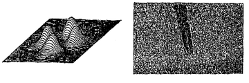
FIG. 10 shows optical radiation images of the laser diode recorded at three distances.
FIG. 11 shows a use of the new lens-ended fibers.
FIG. 12 shows a micro-tip that is metallised with the exception of an aperture.
FIG. 13 shows a submicronic probe variant of the present invention.
The invention will be better understood after reading the following description in the light of the figures which illustrate the invention and application thereof.
FIG. 1 shows the end of an optical fiber 4 comprising a core 1 and a duct 2 equipped with a polymer micro-tip 3 made using a Photopolymerisable resin type material, for which the dimensions and geometry may be adjusted by optimising new physicochemical parameters, for example as a function of envisaged applications.
According to a first purpose of the invention, the operational process used to make the micro-tips gives excellent diversity in values of the height (from a few microns to a few hundred microns) and the radius of curvature of the drop deposited at the beginning of the process. The result is that the dimensions of the micro-tip that depend directly on the dimensions of the formulation drop can be precisely controlled depending on the required applications.
The first micro-tip production operation which is shown as an example in FIG. 2, consists of depositing a formulation drop as shown in FIG. 2 a using a pipette 5, at the end of a cleaved fiber 4 instantaneously forming a capillarity meniscus 6 for which the heights and radii of curvature of the formulation drop are directly related to the diameter of the fiber and to surface tensions (capillarity), as can be seen in FIG. 2 b. These values depend essentially on the viscosity of the formulation used. The viscosity parameter takes an overriding importance for the first objective of the invention. According to the invention, the chemical composition of the formulation is firstly adapted to the required viscosity value, but the formulation temperature also plays a very important role.
Thus, the height of the deposited drop will be reduced by slightly heating the formulation which will make it less viscous. Conversely, the deposited drop will be cooled in advance to make the formulation more viscous and to obtain a larger drop height. For example, a variation of the resin temperature making up the formulation between 10° C. and 65° C. will result in drops with a height of between 10 and 50 microns.
In general, it was specified in the text of the first industrial protection deposited by the inventors that the photopolymerisable formulation is a means of making the micro-tip at the end of the fiber behave like a liquid material sensitive to green light and composed of photoinitiators (eosine+MDEA) and a monomer (PETIA).
According to improvements according to our invention, photoinitiators can be modified so that the formulation is sensitive to wave lengths longer than the wave length for green light, namely red light, near infrared light and more precisely to wave lengths frequently used in the field of telecommunications (for example 1.3 and 1.55 μm).
According to another aspect of the first purpose of the invention, the surface tensions that are directly related to the viscosity of the formulation can also be modified by applying a preliminary treatment to the fiber before the drop is deposited. Preferably (but not limitatively) this treatment consists of dipping the cleaved optical fiber into sulfochromic acid for 24 hours. The surface of the fiber is made hydrophilic, and the attenuated capillarity phenomenon results in a small drop height (for example 10 microns).
The final width of the micro-tip depends on the diameter of the fiber core that guides almost all of the light (usually green light) to the end of the fiber at which the formulation drop was deposited.
The light exposure conditions, and particularly the value of polymerising light intensity and its application time, are also important parameters that should be adjusted as a function of needs.
The final radius of curvature of the micro-tip to be made is much smaller than the radius of curvature of the drop, and is an important factor in obtaining the lens-ended characteristics required for the micro-tip. This radius of curvature may be adjusted as a function of the exposure time (0.5 to 90 seconds as a non-limitative example) and the intensity of photopolymerising light injected into the fiber (fiber output current from 1 to 100 μwatts, as a non-limitative example).
The radius of curvature of the micro-tip also depends on oxygen effects at the drop/air interface. According to the invention, oxygen effects are controlled by adjusting the air composition close to the operational field. Non-limitatively, nitrogen can be injected into a glove box type sealed compartment in which the end of the fiber is inserted.
According to this first purpose of the invention, the operational process and the various micro-tip parameters concerned are not only optimised in order to have good control over production of the various micro-tips and their required characteristics in the many possible applications, but also with the objective of developing a simple and inexpensive manufacturing process capable of “mass production” of fiber end micro-tips.
According to a non-limitative aspect of the first purpose of the invention, the laser radiation necessary for photopolymerisation is distributed into a large number of optical fibers that will be equipped with an end micro-tip, after broadening and homogenisation of the light beam by known optical processes.
The optical power necessary for photopolymerisation is only a few microwatts per micro-tip, consequently “mass production” of more than 100 micro-tips simultaneously (non-limitative example) would be possible according to our invention.
According to a second purpose of the invention and in accordance with FIG. 3, essential aspects of previous technologies and processes improved according to the first purpose of the invention, are applied to multimode and monomode fibers to make fibrous compounds providing a beam that can be either focused (FIG. 3 a) or collimated (FIG. 3 b).
In the special case of multimode fibers, incident light initialising polymerisation preferably originates from a source external to the multimode fiber associated with shaping components of the beam output by the source.
Photopolymerisation is then done without any longitudinal propagation of polymerising light in the multimode fiber itself. The result is thus to avoid illuminating the formulation with all the various transverse modes propagating in multimode fibers when the photopolymerising light is injected at the end of the fibers.
In this case, the geometry of the micro lens produced is similar to the geometry of the formulation drop that was previously deposited.
According to other aspects of the second purpose of the invention, and when some applications make it necessary for the geometry of the micro-tip to be independent of the current distribution between fiber modes, the polymer micro-tip can be made by coupling a white light source to the other end of the fiber outputting incoherent light chosen such that the spectrum of transmitted wave lengths is compatible with the various modes that could be propagated in the fiber. Also in the case of some applications that require compact installations in which it is difficult to envisage the presence of a monochromatic light source close to the end of the usually multimode fiber and therefore the micro-tip to be made, either for location reasons or more generally due to a complex arrangement of the micro-tip production equipment as a whole, the photopolymerising light source used is also non-limitatively an incoherent white light source.
According to a third purpose of the invention, the various improvements made described in the first and second purposes of the invention and associated with the corresponding detailed knowledge of micro-tip properties as a function of the conditions for their production and general techniques for the connection of optical elements, were developed and are applicable for many applications.
The main connection types according to the invention and given non-limitatively are shown in the following figures.
FIG. 4 shows a type of monomode or multimode fiber-to-fiber connection.
The photopolymerising light 7 is injected into the ends of two fibers 4 to be connected and aligned. The contact between the fibers is made by a polymer formulation in the form of a film 8 made using the same technological process claimed for making the micro-tips. The result is a “cold” solder together with an optical jacket such as glue with an index less than the index of the film, and by a mechanical protective jacket. The insertion losses of such a connection may be as low as 0.1 db.
FIG. 5 diagrammatically shows a laser diode 9 to an optical fiber 4 type connection.
In this type of connection, the micro-tip 3 made at the end of the fiber 4 is sized such that the coupling between the radiation from the laser 10 and the micro-tip 3 is maximum.
The connections shown in FIGS. 4 and 5 are only given as examples and are therefore non-exhaustive.
In the context of this third purpose of the invention, integrated optical wave guides, for example, can be connected using the same simple technologies described above, despite the number and complexity of optoelectronic circuits included in them.
According to a fourth purpose of the invention, micro-tips are made at the ends of multimode fibers capable of propagating one or several modes only.
Before exposure of the formulation drop to light, the required mode(s) is (are) selected by applying mechanical stresses to the multimode fiber and modifying the conditions of injection of green light until the required mode(s) is (are) obtained.
As an example shown in FIG. 6, a double polymer micro-tip 11, which is made (FIG. 6 a) on a fiber with a 9 micron core, only transmits mode LP 11 of fiber 4, starting from radiation 12. The intensity distribution 12 bis transmitted by the double micro-tip 11 is shown in FIG. 7 a, which is the same intensity distribution used to create the double micro-tip 11. FIG. 7 b shows the double micro-tip polymer element after its manufacture.
Conversely, the polymer micro-tip 11 can be used as “input” to a fiber illuminated by an incident light beam 12 (FIG. 6 b), light energy is transmitted by micro-tip 11 in the multimode fiber according to a spatial distribution corresponding to the LP mode 11 in the example chosen. Only the LP mode 11 is excited in the fiber, regardless of the injection conditions in the fiber.
According to another example embodiment, a polymer multi-micro-tip was made that can be used to select the LP mode 21 on a multimode fiber with a core diameter of 9 microns. The intensity distribution at the output from the fiber in which the light 12 a was injected by the micro-tip according to LP mode 21 is shown in FIG. 8 a. FIG. 8 b shows the polymer element with 4 micro-tips after manufacturing.
Thus according to our invention, it is possible to make “Transverse mode filters” and more generally new devices called “Mode selectors”.
According to a fifth purpose of the invention, the new lens-ended optical fibers optimised according to the invention are used as optical radiation measurement probes with an excellent resolution better than 1 micron.
As an example of the use of these new probes, FIG. 9 diagrammatically shows a device according to the invention for measuring energy emitted by a laser 13 and particularly the configuration of the optical field curves at the output from the laser.
The laser 13 used in the experiment is a laser diode marketed by the SHARP Company with a 200 μm wide active layer.
The end of the lens-ended optical fiber 4 fitted with its micro-tip 3 is moved successively along 3 planes at distances of 2.5 μm, 1 μm and 0.1 μm respectively from the diode.
The other end of the non lens-ended fiber 4 is connected to a photomultiplier 14, increasing the measurement sensitivity.
FIG. 10 shows optical radiation images of the laser diode recorded at three distances (2.5, 1 and 0.1 μm), the lens-ended optical fiber being moved within an area of 8×8 μm2. Note in FIG. 10 that as the distance from the micro-tip to the laser diode decreases, the active layer of the laser becomes more visible. Furthermore, a clear distinction can be seen between curves of progressively decreasing optical levels for a distance for example of 2.5 μm from the micro-tip to the surface of the fiber 4.
According to a sixth purpose of the invention, some optimisations of lens-ended optical fibers according to the invention are particularly aimed at applications of these fibers in microscopy and in the manufacture of the corresponding measurement probes.
In the case of optical microscopy with conventional scanning, the new lens-ended optical fibers are used as shown in FIG. 11 as a measurement probe for light diffused by the surface of an object 15 illuminated by an external source 16. An optical image of the studied area can be produced by moving the lens-ended optical fiber above the object.
Thus, high resolution optical scanning microscopy can be done using a simple very low cost probe. Resolutions of 300 to 500 nm can easily be obtained.
In the case of optical microscopy applications in near field, the polymer micro-tip of a lens-ended fiber optimised according to the invention is fully metallised, as is shown in FIG. 12, except for a circular nano-aperture 18 formed in the metallisation 17, with a typical diameter of a few tens of nanometres. This nano-aperture remains capable of emitting or receiving light in optical microscopic experiments in the near field. This type of lens-ended fiber with a metallised micro-tip generally acts as a nano-source or a nano-collector, depending on the needs.
The nature of the metal used covering almost the entire micro-tip is preferably but not limitatively chromium or gold.
According to one variant of a submicronic probe shown in FIG. 13, fluorescent particles 19 are included in the photopolymerisable formulation in order to obtain a micro-tip end containing some particles for which the selective optical excitation improves the spatial resolution in optical microscopy. The size of the fluorescent particles added to the formulation is less than one micron. The particle concentration is adjusted to obtain one or several particles at the end of the micro-tip, after formation of the micro-tip. The fluorescence of the particles is then selectively excited through the fiber to obtain a localised light source 15 capable of probing the optical properties of a sample in the near field with a precision better than one micron.
Note that an apparently similar approach for producing probes with a resolution better than one micron in optical microscopy applications in the near field by particle integration, was recently validated by research workers J. MICHAELLS et al. However, the method used by these research workers is very complex, and moreover it is not certain that particle adhesion takes place at the ends of the probes.
The particle probe type according to one of the purposes of our invention enables the use of a much simpler and more reliable process.
For the sixth purpose of the invention, the metallised probes described above but without nano-apertures can be used as surface plasmon sensors. A monomode or multimode lens-ended optical fiber improved according to the invention is used.
The polymer micro-tip is coated with fine metallisation, preferably with gold or silver.
The characteristics of plasmons can be modified by varying the optical index of the external medium, by injecting light into the other cleaved end of the fiber and setting up conditions for excitation of surface plasmons at the metal-air interface. Thus, the presence of chemical or biological substances in contact with the metallic layer will cause modifications of the optical properties of plasmons, therefore variations of the light signal transmitted or reflected by the end of the fiber fitted with the metallised polymer micro-tip.