US7064504B2 - Control apparatus for brushless DC motor - Google Patents

Control apparatus for brushless DC motor Download PDF

Info

Publication number
US7064504B2
US7064504B2 US10/846,932 US84693204A US7064504B2 US 7064504 B2 US7064504 B2 US 7064504B2 US 84693204 A US84693204 A US 84693204A US 7064504 B2 US7064504 B2 US 7064504B2
Authority
US
United States
Prior art keywords
value
sine
rotor
brushless
rotation angle
Prior art date
Legal status (The legal status is an assumption and is not a legal conclusion. Google has not performed a legal analysis and makes no representation as to the accuracy of the status listed.)
Active
Application number
US10/846,932
Other versions
US20050029972A1 (en
Inventor
Nobuyuki Imai
Yutaka Takahashi
Masato Miyauchi
Current Assignee (The listed assignees may be inaccurate. Google has not performed a legal analysis and makes no representation or warranty as to the accuracy of the list.)
Honda Motor Co Ltd
Original Assignee
Honda Motor Co Ltd
Priority date (The priority date is an assumption and is not a legal conclusion. Google has not performed a legal analysis and makes no representation as to the accuracy of the date listed.)
Filing date
Publication date
Application filed by Honda Motor Co Ltd filed Critical Honda Motor Co Ltd
Assigned to HONDA MOTOR CO., LTD. reassignment HONDA MOTOR CO., LTD. ASSIGNMENT OF ASSIGNORS INTEREST (SEE DOCUMENT FOR DETAILS). Assignors: IMAI, NOBUYUKI, MIYAUCHI, MASATO, TAKAHASHI, YUTAKA
Publication of US20050029972A1 publication Critical patent/US20050029972A1/en
Application granted granted Critical
Publication of US7064504B2 publication Critical patent/US7064504B2/en
Active legal-status Critical Current
Anticipated expiration legal-status Critical

Links

Images

Classifications

    • BPERFORMING OPERATIONS; TRANSPORTING
    • B60VEHICLES IN GENERAL
    • B60LPROPULSION OF ELECTRICALLY-PROPELLED VEHICLES; SUPPLYING ELECTRIC POWER FOR AUXILIARY EQUIPMENT OF ELECTRICALLY-PROPELLED VEHICLES; ELECTRODYNAMIC BRAKE SYSTEMS FOR VEHICLES IN GENERAL; MAGNETIC SUSPENSION OR LEVITATION FOR VEHICLES; MONITORING OPERATING VARIABLES OF ELECTRICALLY-PROPELLED VEHICLES; ELECTRIC SAFETY DEVICES FOR ELECTRICALLY-PROPELLED VEHICLES
    • B60L15/00Methods, circuits, or devices for controlling the traction-motor speed of electrically-propelled vehicles
    • B60L15/02Methods, circuits, or devices for controlling the traction-motor speed of electrically-propelled vehicles characterised by the form of the current used in the control circuit
    • B60L15/025Methods, circuits, or devices for controlling the traction-motor speed of electrically-propelled vehicles characterised by the form of the current used in the control circuit using field orientation; Vector control; Direct Torque Control [DTC]
    • BPERFORMING OPERATIONS; TRANSPORTING
    • B60VEHICLES IN GENERAL
    • B60LPROPULSION OF ELECTRICALLY-PROPELLED VEHICLES; SUPPLYING ELECTRIC POWER FOR AUXILIARY EQUIPMENT OF ELECTRICALLY-PROPELLED VEHICLES; ELECTRODYNAMIC BRAKE SYSTEMS FOR VEHICLES IN GENERAL; MAGNETIC SUSPENSION OR LEVITATION FOR VEHICLES; MONITORING OPERATING VARIABLES OF ELECTRICALLY-PROPELLED VEHICLES; ELECTRIC SAFETY DEVICES FOR ELECTRICALLY-PROPELLED VEHICLES
    • B60L50/00Electric propulsion with power supplied within the vehicle
    • B60L50/10Electric propulsion with power supplied within the vehicle using propulsion power supplied by engine-driven generators, e.g. generators driven by combustion engines
    • B60L50/16Electric propulsion with power supplied within the vehicle using propulsion power supplied by engine-driven generators, e.g. generators driven by combustion engines with provision for separate direct mechanical propulsion
    • HELECTRICITY
    • H02GENERATION; CONVERSION OR DISTRIBUTION OF ELECTRIC POWER
    • H02PCONTROL OR REGULATION OF ELECTRIC MOTORS, ELECTRIC GENERATORS OR DYNAMO-ELECTRIC CONVERTERS; CONTROLLING TRANSFORMERS, REACTORS OR CHOKE COILS
    • H02P21/00Arrangements or methods for the control of electric machines by vector control, e.g. by control of field orientation
    • H02P21/14Estimation or adaptation of machine parameters, e.g. flux, current or voltage
    • H02P21/18Estimation of position or speed
    • HELECTRICITY
    • H02GENERATION; CONVERSION OR DISTRIBUTION OF ELECTRIC POWER
    • H02PCONTROL OR REGULATION OF ELECTRIC MOTORS, ELECTRIC GENERATORS OR DYNAMO-ELECTRIC CONVERTERS; CONTROLLING TRANSFORMERS, REACTORS OR CHOKE COILS
    • H02P6/00Arrangements for controlling synchronous motors or other dynamo-electric motors using electronic commutation dependent on the rotor position; Electronic commutators therefor
    • H02P6/14Electronic commutators
    • H02P6/16Circuit arrangements for detecting position
    • H02P6/18Circuit arrangements for detecting position without separate position detecting elements
    • HELECTRICITY
    • H02GENERATION; CONVERSION OR DISTRIBUTION OF ELECTRIC POWER
    • H02PCONTROL OR REGULATION OF ELECTRIC MOTORS, ELECTRIC GENERATORS OR DYNAMO-ELECTRIC CONVERTERS; CONTROLLING TRANSFORMERS, REACTORS OR CHOKE COILS
    • H02P2207/00Indexing scheme relating to controlling arrangements characterised by the type of motor
    • H02P2207/05Synchronous machines, e.g. with permanent magnets or DC excitation
    • YGENERAL TAGGING OF NEW TECHNOLOGICAL DEVELOPMENTS; GENERAL TAGGING OF CROSS-SECTIONAL TECHNOLOGIES SPANNING OVER SEVERAL SECTIONS OF THE IPC; TECHNICAL SUBJECTS COVERED BY FORMER USPC CROSS-REFERENCE ART COLLECTIONS [XRACs] AND DIGESTS
    • Y02TECHNOLOGIES OR APPLICATIONS FOR MITIGATION OR ADAPTATION AGAINST CLIMATE CHANGE
    • Y02TCLIMATE CHANGE MITIGATION TECHNOLOGIES RELATED TO TRANSPORTATION
    • Y02T10/00Road transport of goods or passengers
    • Y02T10/60Other road transportation technologies with climate change mitigation effect
    • Y02T10/64Electric machine technologies in electromobility
    • YGENERAL TAGGING OF NEW TECHNOLOGICAL DEVELOPMENTS; GENERAL TAGGING OF CROSS-SECTIONAL TECHNOLOGIES SPANNING OVER SEVERAL SECTIONS OF THE IPC; TECHNICAL SUBJECTS COVERED BY FORMER USPC CROSS-REFERENCE ART COLLECTIONS [XRACs] AND DIGESTS
    • Y02TECHNOLOGIES OR APPLICATIONS FOR MITIGATION OR ADAPTATION AGAINST CLIMATE CHANGE
    • Y02TCLIMATE CHANGE MITIGATION TECHNOLOGIES RELATED TO TRANSPORTATION
    • Y02T10/00Road transport of goods or passengers
    • Y02T10/60Other road transportation technologies with climate change mitigation effect
    • Y02T10/70Energy storage systems for electromobility, e.g. batteries
    • YGENERAL TAGGING OF NEW TECHNOLOGICAL DEVELOPMENTS; GENERAL TAGGING OF CROSS-SECTIONAL TECHNOLOGIES SPANNING OVER SEVERAL SECTIONS OF THE IPC; TECHNICAL SUBJECTS COVERED BY FORMER USPC CROSS-REFERENCE ART COLLECTIONS [XRACs] AND DIGESTS
    • Y02TECHNOLOGIES OR APPLICATIONS FOR MITIGATION OR ADAPTATION AGAINST CLIMATE CHANGE
    • Y02TCLIMATE CHANGE MITIGATION TECHNOLOGIES RELATED TO TRANSPORTATION
    • Y02T10/00Road transport of goods or passengers
    • Y02T10/60Other road transportation technologies with climate change mitigation effect
    • Y02T10/7072Electromobility specific charging systems or methods for batteries, ultracapacitors, supercapacitors or double-layer capacitors

Definitions

  • the present invention relates to a control apparatus for a brushless DC motor including a rotor having a permanent magnet, and a stator that generates a rotating magnetic field for rotating the rotor.
  • Vehicles having a power source for driving a vehicle, including a brushless DC motor using a permanent magnet as a field magnetic, such as fuel cell vehicles, electric vehicles, or hybrid vehicles.
  • a known control apparatus for such a brushless DC motor is a control apparatus that measures a phase current supplied to each phase of a brushless DC motor, converts a measurement value of the phase current to a d-axis current and a q-axis current on orthogonal coordinates rotating in synchrony with a rotor.
  • d-q coordinates with a direction of a magnetic flux of the rotor in a d-axis (a field axis) and a direction orthogonal to the d-axis in a q-axis (a torque axis), performs feedback control so that a difference between a command value and the measurement value of the current becomes zero on the d-q coordinates.
  • each voltage command value is calculated with respect to a phase voltage supplied to each phase of the brushless DC motor, for example, three phases: a U-phase, a V-phase, and a W-phase.
  • each voltage command value is input as a switching command to an inverter constituted by a switching element such as a transistor, and AC power for driving the brushless DC motor is output from the inverter according to the switching command.
  • the fact that the phase difference ⁇ can be approximated by a sine value (sin ⁇ ) of the phase difference ⁇ (sin ⁇ ) when the phase difference ⁇ is sufficiently small is used to calculate a sine component of an induced voltage including the sine value (sin ⁇ ) of the phase difference ⁇ .
  • a rotational angular velocity of the rotor when the phase difference ⁇ is zero is corrected by a value obtained by controlling and amplifying the sine component of the induced voltage by, for example, a PI (proportional integral) action, a value obtained by the correction is set as a rotational angular velocity on the ⁇ axes, and then the rotational speed on the ⁇ axes is time-integrated to estimate the rotation angle of the rotor.
  • PI proportional integral
  • the brushless DC motor when included as a drive source of a vehicle, the angular velocity of the rotor often varies significantly, and frequent loss of synchronization impairs traveling of the vehicle.
  • the present invention was made in view of the above described circumstances, and has an object to provide a control apparatus for a brushless DC motor capable of improving estimation accuracy when a rotation angle of a rotor is estimated based on an induced voltage in position sensorless control of the brushless DC motor.
  • the present invention provides a control apparatus for a brushless DC motor that rotatably drives the brushless DC motor including a rotor having a permanent magnet, and a stator having stator windings of a plurality of phases that generate a rotating magnetic field for rotating the rotor, by a current passage switching device constituted by a plurality of switching elements and performing successive commutation of current to the stator windings, the control apparatus including: an angular error calculation device for calculating a sine value and a cosine value of an angular difference between an estimated rotation angle with respect to the rotation angle of the rotor and an actual rotation angle, based on a line voltage that is a difference between phase voltages of the plurality of phases on an input side of the stator winding and phase currents of the plurality of phases; and an observer for calculating the rotation angle of the rotor based on the sine value and the cosine value of the angular difference.
  • the angular error calculation device calculates a phase angle of an induced voltage relating to a magnetic pole position of the rotor, that is, the sine value and the cosine value of the angular difference between the estimated rotation angle with respect to the rotation angle of the rotor and the actual rotation angle, by a line voltage model based on the line voltage that is the difference between the phase voltages of the plurality of phases on the input side of the stator winding and the phase currents of the plurality of phases.
  • the observer uses, for example, the rotation angle and an angular velocity of the rotor calculated in the former processing as calculation parameters based on the sine value and the cosine value of the angular difference calculated by the angular error calculation device, performs a following calculation processing so as to converge the angular difference between the estimated rotation angle and the actual rotation angle calculated in the former processing to zero, and successively updates the calculation parameters for calculation.
  • using the line voltage model allows the estimated rotation angle to be estimated with high accuracy regardless of a current waveform of the phase current and a voltage waveform of the phase voltage, for example, even if the current waveform and the voltage waveform are deformed from sine waves or are not sine waves.
  • a current waveform of an appropriate sine wave allows the estimated rotation angle to be estimated with high accuracy regardless of whether the brushless DC motor has saliency, that is, even if the brushless DC motor has saliency.
  • the angular error calculation device may calculate a sine component and a cosine component of an induced voltage constituted by the sine value and the cosine value of the angular difference
  • the angular error calculation device may include: an angular velocity state function calculation device for calculating a state function in proportion to an angular velocity of the rotor based on the sine component and the cosine component of the induced voltage; and a normalization device for dividing the sine component of the induced voltage by the state function in proportion to the angular velocity of the rotor.
  • the normalization device divides the sine component of the induced voltage calculated in the angular error calculation device by the state function in proportion to the angular velocity of the rotor calculated in the angular velocity state function calculation device, and inputs a value obtained by the division to the observer as an input value to the following calculation processing in the observer.
  • the observer performs the following calculation processing so as to converge the angular difference between the estimated rotation angle and the actual rotation angle to zero, and the angular difference or a value relating to the angular difference is input to the observer as the input value. If the angular difference is sufficiently small, the value of the angular difference can be approximated by the sine value of the angular difference, and thus the angular error calculation device calculates the sine component of the induced voltage including the sine value of the angular difference based on the line voltage model, and inputs the sine component to the observer.
  • the error in the sine component of the induced voltage increases in proportion to the angular velocity of the rotor.
  • dividing the sine component of the induced voltage by the state function in proportion to the angular velocity of the rotor causes the error in the input value to the following calculation processing in the observer to be independent of the angular velocity of the rotor, thus allowing the estimated rotation angle to be estimated with high accuracy.
  • the angular error calculation device may calculate the sine component and the cosine component of the induced voltage constituted by the sine value and the cosine value of the angular difference, and the angular error calculation device may include: a revolution speed measuring device for measuring the revolution speed of the brushless DC motor; an angular velocity calculation device for calculating the angular velocity of the rotor based on the revolution speed of the brushless DC motor; and a normalization device for dividing the sine component of the induced voltage by the angular velocity of the rotor.
  • the normalization device divides the sine component of the induced voltage used in the angular error calculation device by the angular velocity of the rotor measured by the revolution speed measuring device, and inputs a value obtained by the division to the observer as an input value to the following calculation processing in the observer.
  • the revolution speed measuring device can measure the angular velocity of the rotor based on an output from the engine revolution speed sensor that measures the revolution speed of the internal combustion engine, thus allowing the device configuration to be simplified.
  • the angular error calculation device may calculate the sine component and the cosine component of the induced voltage constituted by the sine value and the cosine value of the angular difference, and the angular error calculation device may include: a coefficient acting device for causing a predetermined coefficient according to the estimated rotation angle to act on the sine component and the cosine component of the induced voltage; and a phase current differential value calculation device for calculating a differential value of the phase current, and the sine value and the cosine value of the angular difference is calculated based on Formula (2),
  • the phase current differential value calculation device may calculate, by a least squares method, variations of current measured values per unit time at past predetermined times with respect to at least three of the current measured values of the phase currents that form time-series data, and the phase current differential value calculation device may include: a phase voltage correction device for correcting a time delay relating to the past predetermined times with respect to the phase voltages of the plurality of phases for calculating the line voltage; and a control angle correction device for correcting a time delay relating to an appropriate past time with respect to a control angle relating to the rotation angle of the rotor used when the phase currents of the plurality of phases are converted to a d-axis current and a q-axis current on d-q coordinates that form rotating orthogonal coordinates, and feedback control is performed so that a difference between a command value and a measured value of each current on the d-q coordinates becomes zero.
  • the phase current differential value calculation device calculates a current differential value from the plurality of current measured values that form the time-series data, and thus the calculated current differential value becomes a value at the past predetermined time. Correcting the phase voltage for calculating the line voltage and the control angle used in a feedback processing of the current corresponding to the time delay allows the estimated rotation angle to be estimated with high accuracy.
  • the current passage switching device may include a bridge circuit with the plurality of switching elements connected by bridges, and the control apparatus may further include a dead time correction device for correcting the phase voltages of the plurality of phases for calculating the line voltage, based on a dead time in which two of the switching elements connected in series for each phase in the bridge circuit are set to an off state, and polarities of the phase currents.
  • the magnitude of an output voltage of the current passage switching device varies according to the length of the dead time of the current passage switching device, positive or negative polarities of the phase currents, and a power supply voltage supplied to the current passage switching device, and the phase of the induced voltage varies as the output voltage varies.
  • correcting the dead time with respect to the phase voltages with the plurality of phases for calculating the line voltage allows the estimated rotation angle to be estimated with high accuracy.
  • the observer may include an angular difference correction device for correcting the angular difference when the cosine value of the angular difference is negative.
  • the control apparatus for a brushless DC motor configured as described above, when the sine component of the induced voltage including the sine value of the angular difference is input as the input value to the following calculation processing in the observer, the angular difference is sufficiently small, and the value of the angular difference can be approximated by the sine value of the angular difference.
  • the cosine value of the angular difference is negative, that is, when an absolute value of the angular difference is larger than ⁇ /2, correcting the value of the angular difference approximated by the sine value of the angular difference allows the estimated rotation angle to be estimated with high accuracy.
  • the observer may include an angular difference correction device for correcting the angular difference according to a magnitude relation of absolute values of the sine value and the cosine value of the angular difference.
  • the control apparatus for a brushless DC motor configured as described above, when the sine component of the induced voltage including the sine value of the angular difference is input as the input value to the following calculation processing in the observer, the angular difference is sufficiently small, and the angular difference can be approximated by the sine value of the angular difference.
  • the sine value of the angular difference is larger than the cosine value of the angular difference, that is, when the absolute value of the angular difference is larger than ⁇ /4, correcting the value of the angular difference approximated by the sine value of the angular difference allows the estimated rotation angle to be estimated with high accuracy.
  • the present invention further provides a control apparatus for a brushless DC motor that rotatably drives the brushless DC motor including a rotor having a permanent magnet, and a stator having stator windings of a plurality of phases that generate a rotating magnetic field for rotating the rotor, by a current passage switching device constituted by a plurality of switching elements and performing successive commutation of current to the stator windings, according to voltages of a plurality of phases converted from two phase voltages constituted by a d-axis voltage and a q-axis voltage.
  • the present invention includes: an angular error calculation device for calculating a sine component and a cosine component of an induced voltage constituted by a sine value and a cosine value of an angular difference between an estimated rotation angle with respect to a rotation angle of the rotor and an actual rotation angle, by a d-q axes calculation model that describes a state of the brushless DC motor based on the d-axis voltage and the q-axis voltage, an inductance component value, and a d-axis current and a q-axis current; a normalization device for dividing the sine component of the induced voltage by a state function in proportion to an angular velocity of the rotor calculated based on the sine component and the cosine component of the induced voltage, or by an angular velocity of the rotor calculated based on a measured value of the revolution speed of the brushless DC motor; and an observer for calculating the rotation angle of the rotor based on the sine value and the cosine value of
  • the normalization device divides the sine component of the induced voltage calculated in the angular error calculation device by the angular velocity of the rotor or the state function in proportion to the angular velocity of the rotor, and inputs a value obtained by the division to the observer as an input value to a following calculation processing in the observer.
  • the observer performs the following calculation processing so as to converge the angular difference between the estimated rotation angle and the actual rotation angle to zero, and the angular difference or a value relating to the angular difference is input to the observer as the input value. If the angular difference is sufficiently small, the value of the angular difference can be approximated by the sine value of the angular difference, and thus the angular error calculation device calculates the sine component of the induced voltage including the sine value of the angular difference based on the d-q axes calculation model, and inputs the sine component to the observer.
  • the error in the sine component of the induced voltage increases in proportion to the angular velocity of the rotor.
  • dividing the sine component of the induced voltage by the angular velocity of the rotor or the state function in proportion to the angular velocity of the rotor causes the error in the input value to the following calculation processing in the observer to be independent of the angular velocity of the rotor, thus allowing the estimated rotation angle to be estimated with high accuracy.
  • the present invention further provides a control method for a brushless DC motor that rotatably drives the brushless DC motor including a rotor having a permanent magnet, and a stator having stator windings of a plurality of phases that generate a rotating magnetic field for rotating the rotor.
  • the control method of the present invention includes the steps of: rotating the DC motor by a current passage switching device constituted by a plurality of switching elements and performing successive commutation of current to the stator windings; calculating, by an angular error calculation device, a sine value and a cosine value of an angular difference between an estimated rotation angle with respect to the rotation angle of the rotor and an actual rotation angle, based on a line voltage that is a difference between phase voltages of the plurality of phases on an input side of the stator winding and phase currents of the plurality of phases; and calculating, by an observer, the rotation angle of the rotor based on the sine value and the cosine value of the angular difference.
  • the angular error calculation device calculates a phase angle of an induced voltage relating to a magnetic pole position of the rotor, that is, the sine value and the cosine value of the angular difference between the estimated rotation angle with respect to the rotation angle of the rotor and the actual rotation angle, by a line voltage model based on the line voltage that is the difference between the phase voltages of the plurality of phases on the input side of the stator winding and the phase currents of the plurality of phases.
  • the observer uses, for example, the rotation angle and an angular velocity of the rotor calculated in the former processing as calculation parameters based on the sine value and the cosine value of the angular difference calculated by the angular error calculation device, performs a following calculation processing so as to converge the angular difference between the estimated rotation angle and the actual rotation angle calculated in the former processing to zero, and successively updates the calculation parameters for calculation.
  • using the line voltage model allows the estimated rotation angle to be estimated with high accuracy regardless of a current waveform of the phase current and a voltage waveform of the phase voltage, for example, even if the current waveform and the voltage waveform are deformed from sine waves or are not sine waves.
  • a current waveform of an appropriate sine wave allows the estimated rotation angle to be estimated with high accuracy regardless of whether the brushless DC motor has saliency, that is, even if the brushless DC motor has saliency.
  • the above control method for a brushless DC motor may further include the steps of: calculating, by the angular error calculation device, a sine component and a cosine component of an induced voltage constituted by the sine value and the cosine value of the angular difference; calculating, by an angular velocity state function calculation device, a state function in proportion to an angular velocity of the rotor based on the sine component and the cosine component of the induced voltage; and dividing, by a normalization device, the sine component of the induced voltage by the state function in proportion to the angular velocity of the rotor so as to be normalized.
  • the normalization device divides the sine component of the induced voltage calculated in the angular error calculation device by the state function in proportion to the angular velocity of the rotor calculated in the angular velocity state function calculation device, and inputs a value obtained by the division to the observer as an input value to the following calculation processing in the observer.
  • the observer performs the following calculation processing so as to converge the angular difference between the estimated rotation angle and the actual rotation angle to zero, and the angular difference or a value relating to the angular difference is input to the observer as the input value. If the angular difference is sufficiently small, the value of the angular difference can be approximated by the sine value of the angular difference, and thus the angular error calculation device calculates the sine component of the induced voltage including the sine value of the angular difference based on the line voltage model, and inputs the sine component to the observer.
  • the error in the sine component of the induced voltage increases in proportion to the angular velocity of the rotor.
  • dividing the sine component of the induced voltage by the state function in proportion to the angular velocity of the rotor causes the error in the input value to the following calculation processing in the observer to be independent of the angular velocity of the rotor, thus allowing the estimated rotation angle to be estimated with high accuracy.
  • the above control method for a brushless DC motor may further include the steps of: calculating a sine component and a cosine component of an induced voltage constituted by the sine value and the cosine value of the angular difference; measuring the revolution speed of the brushless DC motor; calculating the angular velocity of the rotor based on the revolution speed of the brushless DC motor; and dividing the sine component of the induced voltage by the state function in proportion to the angular velocity of the rotor so as to be normalized.
  • the normalization device divides the sine component of the induced voltage used in the angular error calculation device by the angular velocity of the rotor measured by the revolution speed measuring device, and inputs a value obtained by the division to the observer as an input value to the following calculation processing in the observer.
  • the revolution speed measuring device can measure the angular velocity of the rotor based on an output from the engine revolution speed sensor that measures the revolution speed of the internal combustion engine, thus allowing the device configuration to be simplified.
  • the present invention further provides a control method for a brushless DC motor that rotatably drives the brushless DC motor including a rotor having a permanent magnet, and a stator having stator windings of a plurality of phases that generate a rotating magnetic field for rotating the rotor.
  • the control method includes the steps of: rotating the DC motor by a current passage switching device constituted by a plurality of switching elements and performing successive commutation of current to the stator windings, according to voltages of a plurality of phases converted from two phase voltages constituted by a d-axis voltage and a q-axis voltage; calculating, by an angular error calculation device, a sine component and a cosine component of an induced voltage constituted by a sine value and a cosine value of an angular difference between an estimated rotation angle with respect to a rotation angle of the rotor and an actual rotation angle, by a d-q axes calculation model that describes a state of the brushless DC motor based on the d-axis voltage and the q-axis voltage, an inductance component value, and a d-axis current and a q-axis current; dividing, by a normalization device, the sine component of the induced voltage by a state function in proportion to an angular velocity
  • the normalization device divides the sine component of the induced voltage calculated in the angular error calculation device by the state function in proportion to the angular velocity of the rotor calculated in the angular velocity state function calculation device, and inputs a value obtained by the division to the observer as an input value to the following calculation processing in the observer.
  • the observer performs the following calculation processing so as to converge the angular difference between the estimated rotation angle and the actual rotation angle to zero, and the angular difference or a value relating to the angular difference is input to the observer as the input value. If the angular difference is sufficiently small, the value of the angular difference can be approximated by the sine value of the angular difference, and thus the angular error calculation device calculates the sine component of the induced voltage including the sine value of the angular difference based on the d-q axes calculation model, and inputs the sine component to the observer.
  • the error in the sine component of the induced voltage increases in proportion to the angular velocity of the rotor.
  • dividing the sine component of the induced voltage by the state function in proportion to the angular velocity of the rotor causes the error in the input value to the following calculation processing in the observer to be independent of the angular velocity of the rotor, thus allowing the estimated rotation angle to be estimated with high accuracy.
  • the above control method for a brushless DC motor may further include a step of: correcting the angular difference when the cosine value of the angular difference is negative.
  • the angular difference when the sine component of the induced voltage including the sine value of the angular difference is input as the input value to the following calculation processing in the observer, the angular difference is sufficiently small, and the value of the angular difference can be approximated by the sine value of the angular difference.
  • the cosine value of the angular difference is negative, that is, when an absolute value of the angular difference is larger than ⁇ /2, correcting the value of the angular difference approximated by the sine value of the angular difference allows the estimated rotation angle to be estimated with high accuracy.
  • the above control method for a brushless DC motor may further include a step of: correcting the angular difference according to a magnitude relation of absolute values of the sine value and the cosine value of the angular difference.
  • the angular difference when the sine component of the induced voltage including the sine value of the angular difference is input as the input value to the following calculation processing in the observer, the angular difference is sufficiently small, and the angular difference can be approximated by the sine value of the angular difference.
  • the sine value of the angular difference is larger than the cosine value of the angular difference, that is, when the absolute value of the angular difference is larger than ⁇ /4, correcting the value of the angular difference approximated by the sine value of the angular difference allows the estimated rotation angle to be estimated with high accuracy.
  • angular error calculation device observer, angular velocity state function calculation device, normalization device, coefficient acting device, phase current differential value calculation device, dead time correction device constituting the phase current differential value calculation device, and angular difference correction device can be integrated and realized in the form of executing programs in a micro-computer or in micro-computers.
  • FIG. 1 shows a configuration of a control apparatus for a brushless DC motor according to a first embodiment of the invention
  • FIG. 2 is a graph of an example of a relationship between an angular difference ⁇ e and an angular difference estimated value ⁇ es according to a rotational state of the motor;
  • FIG. 3 is a flowchart of operations of the motor control apparatus in FIG. 1 ;
  • FIG. 4 is a flowchart of operations of a control apparatus for a brushless DC motor according to a second variation of the first embodiment
  • FIG. 5 is a flowchart of an angular difference correction processing in FIG. 4 ;
  • FIG. 6 is a graph of an example of variations of an actual angular error and an angular difference approximate value according to the second variation of the first embodiment
  • FIG. 7 is a flowchart of an angular difference correction processing according to a third variation of the first embodiment
  • FIG. 8 is a graph of an example of variations of an actual angular error and an angular difference approximate value according to the third variation of the first embodiment
  • FIG. 9 shows a configuration of a control apparatus for a brushless DC motor according to a fourth variation of the first embodiment
  • FIG. 10 shows a configuration of a control apparatus for a brushless DC motor according to a second embodiment
  • FIG. 11 is a graph of an example of time variations of phase voltage command values V1, V2 and V3 and current measured values I0, I1, I2 and I3 that form time-series data;
  • FIG. 12 shows configuration of a PWM inverter included in a PDU in FIG. 10 ;
  • FIG. 13 shows commutation of a current that occurs in a dead time of the PWM inverter
  • FIG. 14 is a flowchart of operations of the motor control apparatus in FIG. 10 ;
  • FIG. 15A is a graph of time variations of an estimated rotation angle ⁇ estimated without correction of the dead time and an actual rotation angle ⁇ ;
  • FIG. 15B is a graph of time variations of an estimated rotation angle ⁇ estimated with the correction of the dead time and an actual rotation angle ⁇ ;
  • FIG. 16 is a flowchart of operations of a control apparatus for a brushless DC motor according to a second variation of the second embodiment
  • FIG. 17 shows a configuration of a control apparatus for a brushless DC motor according to a fourth variation of the second embodiment
  • FIG. 18A schematically shows a motor according to a fifth variation of the second embodiment.
  • FIG. 18B shows a magnetic circuit of the motor in FIG. 18A .
  • the control apparatus for a brushless DC motor 10 drives and controls a brushless DC motor 12 (hereinafter simply referred to as the motor 12 ) included in, for example, a hybrid vehicle as a drive source together with an internal combustion engine 11 .
  • the motor 12 includes a rotor (not shown) connected in series to the internal combustion engine 11 and having a permanent magnet used as a field, and a stator (not shown) that generates a rotating magnetic field for rotating the rotor.
  • the motor control apparatus 10 includes, as shown in FIG. 1 , a power drive unit (PDU) 13 , a battery 14 , a control unit 15 , an angular error calculation unit 16 , and an observer 17 .
  • PDU power drive unit
  • the motor control apparatus 10 includes, as shown in FIG. 1 , a power drive unit (PDU) 13 , a battery 14 , a control unit 15 , an angular error calculation unit 16 , and an observer 17 .
  • a drive and a regenerative operation of the motor 12 having a plurality of phases are performed by the power drive unit (PDU) 13 that receives a control command output from the control unit 15 .
  • PDU power drive unit
  • the PDU 13 includes, for example, a PWM inverter by pulse width modulation (PWM) having a bridge circuit with a plurality of switching elements of a transistor connected by bridges, and a high voltage battery 14 for supplying and receiving electric energy to and from the motor 12 is connected to the PDU 13 .
  • PWM pulse width modulation
  • the PDU 13 converts DC power supplied from the battery 14 to three-phase AC power based on command values (a U-phase AC voltage command value Vu, a V-phase AC voltage command value Vv, a W-phase AC voltage command value Vw) output from the control unit 15 , performs successive commutation of current to a stator winding of the three-phase motor 12 , and thus outputs a U-phase current Iu, a V-phase current Iv, and a W-phase current Iw corresponding to the voltage command values Vu, Vv and Vw to the phases of the motor 12 .
  • command values a U-phase AC voltage command value Vu, a V-phase AC voltage command value Vv, a W-phase AC voltage command value Vw
  • the control unit 15 performs feedback control of current on d-q coordinates that form rotating orthogonal coordinates, calculates the voltage command values Vu, Vv and Vw based on an Id command and an Iq command, inputs pulse width modulation signals to the PDU 13 , and controls so that each difference becomes zero between a d-axis current Id and a q-axis current Iq and the Id command and the Iq command, respectively, obtained by converting the phase currents Iu, Iv and Iw actually supplied from the PDU 13 to the motor 12 on the d-q coordinates.
  • the control unit 15 includes, for example, a current command input unit 21 , subtracters 22 and 23 , a current feedback control unit 24 , a dq-three phase conversion unit 25 , and a three phase-dq conversion unit 26 .
  • the current command input unit 21 calculates a current command for specifying the phase currents Iu, Iv and Iw supplied from the PDU 13 to the motor 12 based on a torque command value for causing the motor 12 to generate a torque value required according to the amount of acceleration operation relating to driver's depression of an accelerator pedal and the revolution speed of the motor 12 , and the current command is output to the subtracters 22 and 23 as the Id command and the Iq command on the rotating orthogonal coordinates.
  • the d-q coordinates that form the rotating orthogonal coordinates sets, for example, a direction of a magnetic flux of a field pole by the permanent magnet of the rotor in a d-axis (a field axis) and sets a direction orthogonal to the d-axis in a q-axis (a torque axis), and rotates at an electrical angular velocity ⁇ (hereinafter simply referred to as the rotational angular velocity ⁇ ) in synchrony with the rotor (not shown) of the motor 12 .
  • the Id command and the Iq command that are DC signals are provided as current commands to AC signals supplied from the PDU 13 to the phases of the motor 12
  • the subtracter 22 calculates a difference ⁇ Id between the Id command and the d-axis current Id, and the subtracter 23 calculates a difference ⁇ Iq between the Iq command and the q-axis current Iq.
  • the differences ⁇ Id and ⁇ Iq output from the subtracters 22 and 23 are input to the current feedback control unit 24 .
  • the current feedback control unit 24 controls and amplifies the difference ⁇ Id to calculate a d-axis voltage command value Vd, and controls and amplifies the difference ⁇ Iq to calculate a q-axis voltage command value Vq by a PI (proportional plus integral) action.
  • the d-axis voltage command value Vd and the q-axis voltage command value Vq output from the current feedback control unit 24 are input to the dq-three phase conversion unit 25 .
  • the dq-three phase conversion unit 25 uses an estimated rotation angle ⁇ with respect to a rotation angle of the rotor input from a below described observer 17 to convert the d-axis voltage command value Vd and the q-axis voltage command value Vq on the d-q coordinates to a U-phase AC voltage command value Vu, a V-phase AC voltage command value Vv, and W-phase AC voltage command value Vw on three-phase AC coordinates that are static coordinates.
  • the voltage command values Vu, Vv and Vw output from the dq-three phase conversion unit 25 are input to the PDU 13 as switching commands (for example, pulse width modulation signals) for turning on/off the switching elements of the PDU 13 .
  • the three phase-dq conversion unit 26 uses the estimated rotation angle ⁇ with respect to the rotation angle of the rotor input from the below described observer 17 to convert the phase currents Iu, Iv and Iw on the static coordinates to the d-axis current Id and the q-axis current Iq on the rotating coordinates by rotational phases of the motor 12 , that is, the d-q coordinates.
  • measured values for example, a U-phase current Iu and a W-phase current Iw
  • the d-axis current Id and the q-axis current Iq output from the three phase-dq conversion unit 26 are output to the subtracters 22 and 23 .
  • the angular error calculation unit 16 includes, for example, a model calculation unit 31 , an angular velocity state function calculation unit 32 , and a normalization unit 33 .
  • the model calculation unit 31 calculates a sine component Vs and a cosine component Vc of an induced voltage constituted by the sine value sin ⁇ e and the cosine value cos ⁇ e of the angular difference ⁇ e by a circuit equation on the d-q coordinates expressed as in Formula (3), based on the d-axis voltage command value Vd and the q-axis voltage command value Vq output from the current feedback control unit 24 and the d-axis current Id and the q-axis current Iq output from the three phase-dq conversion unit 26 .
  • is a rotational angular velocity of the rotor
  • Ke is an induced voltage constant
  • r is a phase resistance
  • L is an inductance component value.
  • the angular velocity state function calculation unit 32 calculates, as expressed in Formula (4), a value ( ⁇ Ke) obtained by multiplying the rotational angular velocity ⁇ by the induced voltage constant Ke as a state function in proportion to the rotational angular velocity ⁇ used in a below described normalization processing in the normalization unit 33 , based on the sine component Vs and the cosine component Vc of the induced voltage calculated in the model calculation unit 31 , and outputs the value to the normalization unit 33 .
  • ⁇ square root over ( Vc 2 +Vs 2 ) ⁇ ⁇ Ke (4)
  • the normalization unit 33 calculates an angular difference approximate value ( ⁇ Vs/(Vs2+Vc2)1 ⁇ 2 ⁇ e) approximated by the angular difference ⁇ e by dividing the sine component Vs of the induced voltage calculated in the model calculation unit 31 by the state function (for example, ⁇ Ke) in proportion to the rotational angular velocity ⁇ calculated in the angular velocity state function calculation unit 32 , and inputs the value to the observer 17 .
  • an angular difference estimated value ⁇ es is set as a value obtained by multiplying the angular difference ⁇ e by the rotational angular velocity ⁇ and the induced voltage constant Ke
  • the angular difference estimated value ⁇ es is expressed as in Formula (5) so that the sine value sin ⁇ e is approximated by the angular difference ⁇ e ( ⁇ e ⁇ sin ⁇ e) in the sine component Vs of the induced voltage in Formula (3), and that voltage drop by the phase resistance r is ignored.
  • the term including the error ⁇ L ( ⁇ LIq) indicates an error in the angular difference estimated value ⁇ es when the angular difference ⁇ e is zero, and increases in proportion to the rotational angular velocity ⁇ .
  • the error in the angular difference estimated value ⁇ es increases more than in a relatively low rotational state of the motor 12 (for example, the solid line L in FIG. 2 ).
  • ⁇ ⁇ ⁇ es ⁇ ⁇ ⁇ K ⁇ ⁇ ⁇ Ke ⁇ ⁇ sin ⁇ ⁇ ⁇ ⁇ ⁇ e + ⁇ ⁇ ⁇ ⁇ ⁇ LI ⁇ ⁇ ⁇ K ⁇ Ke K ⁇ ⁇ ⁇ ⁇ e + ⁇ ⁇ ⁇ LI K ( 7 )
  • the observer 17 sets the value (Vs/(Vs2+Vc2)1 ⁇ 2) obtained by dividing the sine component Vs of the induced voltage approximated by the angular difference estimated value ⁇ es as expressed in Formula (5) by the state function (for example, ⁇ Ke) in proportion to the rotational angular velocity ⁇ calculated in the angular velocity state function calculation unit 32 as expressed in Formula (4), that is, the angular difference approximate value ( ⁇ Vs/(Vs2+Vc2)1 ⁇ 2 ⁇ e) approximated by the angular difference ⁇ e, as an input value to a following calculation processing.
  • the state function for example, ⁇ Ke
  • the observer 17 performs the following calculation processing so as to converge the input value (that is, the angular difference ⁇ e) to zero as expressed in Formula (8), successively updates the estimated rotation angle ⁇ for calculation, and outputs a convergence value of the estimated rotation angle ⁇ to the dq-three phase conversion unit 25 and the three phase-dq conversion unit 26 of the control unit 15 .
  • n is any counting number indicating the number of performance of the following calculation processing repeated at a predetermined time interval ⁇ t
  • K 1 is a control gain (feedback gain) relating to the estimated rotation angle ⁇
  • K 2 is a control gain (feedback gain) relating to a rotational angular velocity estimated value ⁇
  • K ⁇ is an appropriate proportional coefficient including positive and negative signs.
  • offset is a rotation angle of the rotor set in the relatively low rotational state of the motor 12 or in calculation of the actual rotation angle ⁇ .
  • [ ⁇ ⁇ ( n + 1 ) ⁇ ⁇ ( n + 1 ) ] [ 1 ⁇ ⁇ ⁇ t 0 1 ] ⁇ [ ⁇ ⁇ ( n ) ⁇ ⁇ ( n ) ] + [ K1 K2 ] ⁇ K ⁇ ⁇ Vs Vs 2 + Vc 2 ⁇ ⁇ ⁇ [ 1 ⁇ ⁇ ⁇ t 0 1 ] ⁇ ⁇ [ ⁇ ⁇ ( n ) ⁇ ⁇ ( n ) ] + [ K1 K2 ] ⁇ K ⁇ ( ⁇ ⁇ ⁇ e ⁇ ( n ) + offset ) , ⁇ ⁇ ⁇ ( ⁇ ⁇ ⁇ e ⁇ ( n ) ⁇ 0 ( 8 )
  • the motor control apparatus 10 has the above described configuration, and now, operations of the motor control apparatus 10 , more particularly, a calculation processing of the estimated rotation angle ⁇ in sensorless control by the d-q axes calculation model will be described with reference to the accompanying drawings.
  • Step S 01 in FIG. 3 detection results of the current values of the phase currents output from the phase current detectors 27 and 27 , for example, the U-phase current Iu and the W-phase current Iw are obtained.
  • Step S 02 based on the d-axis voltage command value Vd and the q-axis voltage command value Vq, and the d-axis current Id and the q-axis current Iq, the sine component Vs and the cosine component Vc of the induced voltage constituted by the sine value sin ⁇ e and the cosine value cos ⁇ e of the angular difference ⁇ e are calculated by the circuit equation on the d-q coordinates expressed as in Formula (3).
  • Step S 03 based on the sine component Vs and the cosine component Vc of the induced voltage, as expressed in Formula (4), the state function ( ⁇ Ke) in proportion to the rotational angular velocity ⁇ is calculated, and the sine component Vs of the induced voltage is divided by the state function ( ⁇ Ke) to calculate the angular difference approximate value ( ⁇ Vs/(Vs2+Vc2)1 ⁇ 2 ⁇ e).
  • Step S 04 as expressed in Formula (8), the angular difference approximate value ( ⁇ Vs/(Vs2+Vc2)1 ⁇ 2 ⁇ e) is set as the input value to the following calculation processing, the following calculation processing is performed so as to converge the input value (that is, the angular difference ⁇ e) to zero, and thus the estimated rotation angle ⁇ and the rotational angular velocity estimated value ⁇ are subsequently updated for calculation to finish the series of processings.
  • the angular difference approximate value ( ⁇ Vs/(Vs2+Vc2)1 ⁇ 2 ⁇ e) obtained by normalization by the rotational angular velocity ⁇ is set as the input value to the following calculation processing in the observer 17 , thus improving calculation accuracy of the estimated rotation angle ⁇ , compared to the case where an angular difference estimated value ⁇ es that is not normalized by a rotational angular velocity ⁇ is set as an input value to a following calculation processing to calculate an estimated rotation angle ⁇ .
  • the angular difference approximate value (Vs/(Vs2+Vc2)1 ⁇ 2) obtained by dividing the sine component Vs of the induced voltage by the state function (for example, ⁇ Ke) in proportion to the rotational angular velocity c) is set as the input value to the following calculation processing to calculate the estimated rotation angle ⁇ in the observer 17 , but is not limited to this.
  • the angular difference approximate value (Vs/(Vs2+Vc2)1 ⁇ 2) may be further approximated according to the magnitude of absolute values of the sine component Vs and the cosine component Vc of the induced voltage as expressed in Formula (9), and the approximate value (for example, Vs/
  • an angular difference correction processing for correcting the angular difference approximate value ( ⁇ Vs/(Vs2+Vc2)1 ⁇ 2 ⁇ e) set as the input value to the following calculation processing may be performed by correcting the sine component Vs of the induced voltage according to the positive or negative sign of the cosine component Vc of the induced voltage.
  • Step S 03 after the normalization processing in Step S 03 , the process goes to Step 11 to perform a below described angular difference correction processing, and then perform the following calculation processing in Step S 04 .
  • Step S 11 In the angular difference correction processing in Step S 11 , first in Step 21 in FIG. 5 , it is determined whether the cosine component Vc of the induced voltage is less than zero.
  • Step S 22 When it is determined to be “YES”, that is, when the sign of the cosine component Vc of the induced voltage is positive, the process goes to Step S 22 , and the angular difference approximate value ( ⁇ Vs/(Vs2+Vc2)1 ⁇ 2 ⁇ e), that is, the angular difference ⁇ e set as the input value to the following calculation processing is set to Vs/Vc to finish the series of processings.
  • Step S 23 when it is determined to be “NO”, that is, when the sign of the cosine component Vc of the induced voltage is negative, the process goes to Step S 23 , and the angular difference approximate value ( ⁇ Vs/(Vs2+Vc2)1 ⁇ 2 ⁇ e), that is, the angular difference ⁇ e set as the input value to the following calculation processing is set to Vs/
  • an angular difference correction processing for correcting the angular difference approximate value ( ⁇ Vs/(Vs2+Vc2)1 ⁇ 2 ⁇ e) set as the input value to the following collection processing may be performed by correcting the sine component Vs of the induced voltage according to a magnitude relation of absolute values of the sine component Vs and the cosine component Vc of the induced voltage.
  • Step S 32 the process goes to Step S 32 , and the angular difference approximate value ( ⁇ Vs/(Vs2+Vc2)1 ⁇ 2 ⁇ e), that is, the angular difference ⁇ e set as the input value to the following calculation processing is set to Vs/Vc to finish the series of processings.
  • Step S 33 the process goes to Step S 33 , and the angular difference approximate value ( ⁇ Vs/(Vs2+Vc2)1 ⁇ 2 ⁇ e), that is, the angular difference ⁇ e set as the input value to the following calculation processing is set to Vs/
  • the sine component Vs of the induced voltage calculated by the model calculation unit 31 is divided by the state function (for example, ⁇ Ke) in proportion to the rotational angular velocity ⁇ calculated in the angular velocity state function calculation unit 32 , but is not limited to this, as a fourth variation of the first embodiment in FIG. 8 , the angular velocity state function calculation unit 32 may be omitted, an angular velocity calculation unit 36 may be provided that calculates the rotational angular velocity ⁇ of the motor 12 based on the revolution speed of the engine Ne of the internal combustion engine 11 output from an engine revolution speed sensor 35 , and the sine component Vs of the induced voltage may be divided by the rotational angular velocity ⁇ as a normalization processing.
  • the state function for example, ⁇ Ke
  • the motor 12 is connected in series to the internal combustion engine 11 , and thus the rotational angular velocity ⁇ of the motor 12 can be calculated from the revolution speed of the engine Ne in the angular velocity calculation unit 36 , and the normalization unit 33 divides the sine component Vs of the induced voltage calculated in the model calculation unit 31 by the rotational angular velocity ⁇ output from the angular velocity calculation unit 36 to calculate an approximate value ( ⁇ Vs/ ⁇ Ke ⁇ e) approximated by a value (Ke ⁇ e) obtained by multiplying the angular difference ⁇ e by the induced voltage constant Ke, and input the value to the observer 17 .
  • the observer 17 sets the approximate value ( ⁇ Vs/ ⁇ Ke ⁇ e) approximated by the value (Ke ⁇ e) obtained by multiplying the angular difference ⁇ e by the induced voltage constant Ke as an input value to the following calculation processing, performs the following calculation processing so as to converge the input value to zero, thus successively updates the estimated rotation angle ⁇ for calculation, and outputs a convergence value of the estimated rotation angle ⁇ to the dq-three phase conversion unit 25 and the three phase-dq conversion unit 26 of the control unit 15 .
  • the control apparatus for a brushless DC motor 40 (hereinafter simply referred to as the motor control apparatus 40 ) according to the second embodiment includes, as shown in FIG. 10 , a power drive unit (PDU) 13 , a battery 14 , a control unit 15 , an observer 17 , an angular error calculation unit 41 , and a control angle correction unit 42 .
  • the angular error calculation unit 41 includes, for example, a model calculation unit 50 , an angular velocity state function calculation unit 32 , and a normalization unit 33 .
  • the model calculation unit 50 calculates a sine component Vs and a cosine component Vc of an induced voltage constituted by the sine value sin ⁇ e and the cosine value cos ⁇ e of the angular difference ⁇ e by a circuit equation in the line voltage model expressed as in Formula (10), based on a U-phase AC voltage command value Vu, a V-phase AC voltage command value Vv, and a W-phase AC voltage command value Vw output from a dq-three phase conversion unit 25 , and measured values (for example, a U-phase current Iu, and a W-phase current Iw) output from two phase current detectors 27 and 27 .
  • r a phase resistance;
  • l a self inductance;
  • m a mutual inductance;
  • a rotational angular velocity of the rotor;
  • Ke an induced voltage constant.
  • the angular velocity state function calculation unit 32 calculates, as expressed in Formula (4), a value ( ⁇ Ke) obtained by multiplying the rotational angular velocity ⁇ by the induced voltage constant Ke as a state function in proportion to the rotational angular velocity ⁇ , based on the sine component Vs and the cosine component Vc of the induced voltage calculated in the model calculation unit 50 , and outputs the value to the normalization unit 33 .
  • the normalization unit 33 calculates an angular difference approximate value ( ⁇ Vs/(Vs2+Vc2)1 ⁇ 2 ⁇ e) approximated by the angular difference ⁇ e by dividing the sine component Vs of the induced voltage calculated in the model calculation unit 50 by the state function (for example, ⁇ Ke) in proportion to the rotational angular velocity ⁇ calculated in the angular velocity state function calculation unit 32 , and inputs the value to the observer 17 .
  • the state function for example, ⁇ Ke
  • the model calculation unit 50 includes, for example, a coefficient acting unit 51 , a phase current differential value calculation unit 52 , a phase voltage correction unit 53 , and a dead time correction unit 54 .
  • the coefficient acting unit 51 causes, based on Formula (10), a matrix A including a predetermined estimated rotation angle ⁇ to act from the left as expressed in Formulas (11) and (12) with respect to an induced voltage component obtained by subtracting voltage drop relating to the phase resistance r and voltage drop relating to the self inductance l and the mutual inductance m from the line voltages Vuv and Vwv.
  • the model calculation unit 50 calculates the sine component Vs and the cosine component Vc of the induced voltage as values in proportion to the sine value sin ⁇ e and the cosine value cos ⁇ e of the angular difference ⁇ e based on Formulas (11) and (12).
  • A 2 3 ⁇ [ cos ⁇ ⁇ ⁇ ⁇ - sin ⁇ ( ⁇ ⁇ + ⁇ 6 ) sin ⁇ ⁇ ⁇ ⁇ cos ⁇ ( ⁇ ⁇ + ⁇ 6 ) ] ( 11 )
  • a ⁇ ⁇ [ Vuv Vwv ] - r ⁇ [ 2 1 1 2 ] ⁇ [ Iu Iw ] - ( I - m ) ⁇ [ 2 1 1 2 ] ⁇ d d t ⁇ [ Iu Iw ] ⁇ 2 3 ⁇ [ cos ⁇ ⁇ ⁇ ⁇ - sin ⁇ ( ⁇ ⁇ + ⁇ 6 ) sin ⁇ ⁇ ⁇ ⁇ cos ⁇ ( ⁇ ⁇ + ⁇ 6 ) ] ⁇ ⁇ [ Vuv Vwv ] - r ⁇ [ 2 1 1 2 ] ⁇ [ Iu Iw ] - ( I - m ) ⁇ [ 2 1 1 2 ] ⁇ d
  • the phase current differential value calculation unit 52 calculates current differential values of the phase currents Iu and Iw included in the term of the voltage drop relating to the self inductance l and the mutual inductance m in Formula (12).
  • a filtering processing such as a least squares method or a moving average value calculation processing
  • L is an approximate line indicating the time variation of the current measured value obtained by the least squares method.
  • the time variation ⁇ I and the current measured value Im corresponding to the time variation ⁇ I, that is, the current measured value Im at the time (t 1 +t 2 )/2 are expressed as in Formula (13) by the current measured values I0, I1, I2 and I3, and Formula (13) is modified as in Formula (14).
  • the phase current differential value calculation unit 52 calculates the time variation ⁇ I of the average current measured value at the predetermined time interval ⁇ t by Formula (14), and sets a time variation of the current measured value per unit time ⁇ I/ ⁇ t obtained by dividing the time variation ⁇ I by the predetermined time interval ⁇ t as a current differential value of the phase current.
  • [ I0 I1 I2 I3 ] [ 1.5 1 0.5 1 - 0.5 1 - 1.5 1 ] ⁇ [ ⁇ ⁇ ⁇ I I ⁇ ⁇ m ] ( 13 )
  • [ ⁇ ⁇ ⁇ I I ⁇ ⁇ m ] [ 0.3 0.1 - 0.1 - 0.3 0.25 0.25 0.25 0.25 ] ⁇ [ I0 I1 I2 I3 ] ( 14 )
  • the phase voltage correction unit 53 corrects the voltage command values Vu, Vw and Vv for calculating the line voltage (for example, the line voltages Vuv and Vwv) according to the filtering processing in the phase current differential value calculation unit 52 .
  • the phase voltage correction unit 53 sets a phase voltage command value at the time (t 1 +t 2 )/2 (for example, the phase voltage command value V1 in FIG. 11 ) as the voltage command values Vu, Vw and Vv for calculating the line voltage (for example, the line voltages Vuv and Vwv).
  • the phase voltage correction unit 53 performs a filtering processing such as a least squares method or a moving average calculation processing with respect to the phase voltage command value V0 from the time t 0 to the time t 1 , the phase voltage command value V1 from the time t 1 to the time t 2 , the phase voltage command value V2 from the time t 2 to the time t 3 , calculates an average phase voltage command value at the past time (t 1 +t 2 )/2 (for example, a moving average value (V0+V1+V2)/3), and sets the command value as the voltage command values Vu, Vw and Vv for calculating the line voltage (for example, the line voltages Vuv and Vwv).
  • a filtering processing such as a least squares method or a moving average calculation processing with respect to the phase voltage command value V0 from the time t 0 to the time t 1 , the phase voltage command value V1 from the time t 1 to the time t 2 , the phase voltage command value V2 from the time
  • a dead time correction unit 54 corrects the voltage command values Vu, Vw and Vv for calculating the line voltage (for example, the line voltages Vuv and Vwv) according to a dead time of a PWM inverter by pulse width modulation (PWM) included in the PDU 13 and polarities of the phase currents Iu, Iv and Iw supplied from the PDU 13 to the motor 12 .
  • PWM pulse width modulation
  • the PWM inverter 13 A in the PDU 13 includes a bridge circuit 13 a with a plurality of switching elements connected by bridges, and a smoothing capacitor C, and the bridge circuit 13 a includes transistors TU 1 , TU 2 , TV 1 , TV 2 , TW 1 and TW 2 that are a plurality of switching elements.
  • diodes DU 1 , DU 2 , DV 1 , DV 2 , DW 1 and DW 2 are placed, between a collector and an emitter of the transistors TU 1 , TU 2 , TV 1 , TV 2 , TW 1 and TW 2 , diodes DU 1 , DU 2 , DV 1 , DV 2 , DW 1 and DW 2 are placed, an anode of each of the diodes DU 1 , DU 2 , DV 1 , DV 2 , DW 1 and DW 2 is connected to the emitter of each of the transistors TU 1 , TU 2 , TV 1 , TV 2 , TW 1 and TW 2 , and a cathode of each of the diodes DU 1 , DU 2 , DV 1 , DV 2 , DW 1 and DW 2 is connected to each collector.
  • the collectors of the transistors TU 1 , TV 1 and TW 1 are connected to a positive pole terminal of the battery 14 .
  • the emitter of the transistor TU 1 is connected to the collector of the transistor TU 2
  • the emitter of the transistor TV 1 is connected to the collector of the transistor TV 2
  • the emitter of the transistor TW 1 is connected to the collector of the transistor TW 2 .
  • the emitters of the transistors TU 2 , TV 2 and TW 2 are connected to a negative pole terminal of the battery 14 .
  • a U-phase stator winding of the motor 12 is connected to the emitter of the transistor TU 1 and the collector of the transistor TU 2 , a V-phase stator winding of the motor 12 is connected to the emitter of the transistor TV 1 and the collector of the transistor TV 2 , and a W-phase stator winding of the motor 12 is connected to the emitter of the transistor TW 1 and the collector of the transistor TW 2 .
  • the smoothing capacitor C is connected between the positive pole terminal and the negative pole terminal of the battery 14 .
  • the PWM inverter 13 A switches on/off the pairs of transistors TU 1 and TU 2 , transistors TV 1 and TV 2 , and transistors TW 1 and TW 2 for each phase to pass an AC phase current to the stator winding of each phase.
  • a dead time is provided for setting both of the pairs of transistors TU 1 and TU 2 , transistors TV 1 and TV 2 , and transistors TW 1 and TW 2 for each phase to an off state.
  • the current is commutated to either of the pairs of diodes DU 1 and DU 2 , diodes DV 1 and DV 2 , and diodes DW 1 and DW 2 for each phase according to the polarity of the phase current to vary an output voltage of the PWM inverter 13 A.
  • both transistors TU 1 and TU 2 are set to the off state when the polarity of the phase current is positive with respect to the transistors TU 1 and TU 2 and the diodes DU 1 and DU 2 of the U-phase (that is, when the U-phase current Iu passes in a direction from the PWM inverter 13 A to the motor 12 ), the current is commutated to the diode DU 2 connected to the negative terminal of the battery 14 to reduce the output voltage.
  • the both transistors TU 1 and TU 2 are set to the off state when the polarity of the phase current is negative (that is, when the U-phase current Iu passes in a direction from the motor 12 to the PWM inverter 13 A), the current is commutated to the diode DU 1 connected to the positive terminal of the battery 14 to increase the output voltage.
  • an actual output voltage (an actual voltage) VR of each phase of the PWM inverter 13 A is expressed as in Formula (15) according to a phase voltage command value Vm, a cycle T of pulse width modulation (PWM), a dead time TD, and a voltage between terminals VB of the battery 14 .
  • the dead time correction unit 54 calculates the actual voltage VR based on Formula (15), and sets the actual voltage as the voltage command values Vu, Vw and Vv for calculating the line voltage (for example, the line voltages Vuv and Vwv).
  • V R Vm - T D T ⁇ V B , ( PHASE ⁇ ⁇ CURRENT > 0 )
  • V R Vm + T D T ⁇ V B , ( PHASE ⁇ ⁇ CURRENT ⁇ 0 ) ⁇ ( 15 )
  • the control angle correction unit 42 corrects a control angle ⁇ c used in a current feedback control unit 24 corresponding to the filtering processing in the phase current differential value calculation unit 52 .
  • the current feedback control unit 24 controls and amplifies a difference ⁇ Id to calculate a d-axis voltage command value Vd, and controls and amplifies a difference ⁇ Iq to calculate a q-axis voltage command value Vq by a PI (proportional plus integral) action according to the control angle ⁇ c.
  • ⁇ c kd ⁇ t ⁇ ( n ) (16)
  • the motor control apparatus 40 has the above described configuration, and now, operations of the motor control apparatus 40 , more particularly, a calculation processing of the estimated rotation angle ⁇ in sensorless control by the line voltage model will be described with reference to the accompanying drawings.
  • Step S 41 detection results of the current values of the phase currents output from the phase current detectors 27 and 27 , for example, the U-phase current Iu and the W-phase current Iw are obtained.
  • Step S 42 the current measured value output from the phase current detector 27 at the predetermined time interval ⁇ t with respect to the phase currents Iu and Iw is set as time-series data, the time variation ⁇ I of the average current measured value at the predetermined time interval ⁇ t is calculated by the least square method based on the current measured value I0 at the present time t 0 and the current measured values I1, I2 and I3 at the past times t 1 , t 2 and t 3 , and the value obtained by dividing the time variation ⁇ I of the calculated current measured value by the predetermined time interval ⁇ t is set as the current differential value of the phase current.
  • Step S 43 according to the filtering processing in the phase current differential value calculation unit 52 , the phase voltage command value output from the dq-three phase conversion unit 25 to the voltage command values Vu, Vw and Vv for calculating the line voltage (for example, the line voltages Vuv and Vwv) at the predetermined time interval ⁇ t is set as time-series data, and the value (V0+V1+V2)/3) obtained by the moving average value calculation processing with respect to the phase voltage command values V0, V1 and V2 are newly set as the voltage command values Vu, Vw and Vv for calculating the line voltage (for example, the line voltages Vuv and Vwv).
  • Step S 44 the actual voltage VR is calculated based on Formula (15) with respect to the voltage command values Vu, Vw and Vv for calculating the line voltage (for example, the line voltages Vuv and Vwv), and newly set as the voltage command values Vu, Vw and Vv for calculating the line voltage (for example, the line voltages Vuv and Vwv).
  • Step S 45 the sine component Vs and the cosine component Vc of the induced voltage constituted by the sine value sin ⁇ e and the cosine value cos ⁇ e of the angular difference ⁇ e are calculated by the circuit equation by the line voltage model expressed in Formula (12), based on the current differential values of the phase currents Iu and Iw, the line voltages Vuv and Vwv calculated from the voltage command values Vu, Vw and Vv, the phase resistance r, the self inductance l, and the mutual inductance m.
  • Step S 46 based on the sine component Vs and the cosine component Vc of the induced voltage, as expressed in Formula (4), the state function (for example, ⁇ Ke) in proportion to the rotational angular velocity ⁇ is calculated, and the sine component Vs of the induced voltage is divided by the state function (for example, ⁇ Ke) to calculate the angular difference approximate value ( ⁇ Vs/(Vs2+Vc2)1 ⁇ 2 ⁇ e).
  • the state function for example, ⁇ Ke
  • Step S 47 as expressed in Formula (8), the angular difference approximate value ( ⁇ Vs/(Vs2+Vc2)1 ⁇ 2 ⁇ e) is set as the input value to the following calculation processing, and the following calculation processing is performed so as to converge the input value (that is, the angular difference ⁇ e) to zero, and thus the estimated rotation angle ⁇ and the rotational angular velocity estimated value ⁇ are subsequently updated for calculation to finish the series of processings.
  • the angular difference approximate value ( ⁇ Vs/(Vs2+Vc2)1 ⁇ 2 ⁇ e) obtained by normalization by the rotational angular velocity ⁇ is set as the input value to the following calculation processing in the observer 17 , thus improving calculation accuracy of the estimated rotation angle ⁇ , compared to the case where an angular difference estimated value ⁇ es that is not normalized by a rotational angular velocity ⁇ is set as an input value to a following calculation processing to calculate an estimated rotation angle ⁇ .
  • calculating the sine component Vs and the cosine component Vc of the induced voltage constituted by the sine value sin ⁇ e and the cosine value cos ⁇ e of the angular difference ⁇ e based on the circuit equation by the line voltage model allows the estimated rotation angle ⁇ to be estimated with high accuracy even if a current waveform and a voltage waveform are deformed from a sine wave or are not a sine wave.
  • the line voltage model allows the sine component Vs of the induced voltage to be calculated even if the rotational angular velocity ⁇ of the rotor is unknown in the first processing, unlike calculation of the sine component Vs of the induced voltage based on the d-q axes calculation model.
  • the phase of the induced voltage is shifted, and thus a large time lag relative to the time variation of the actual rotation angle ⁇ occurs in the time variation of the estimated rotation angle ⁇ estimated without correction of the dead time in FIG. 15A .
  • the time variation of the estimated rotation angle ⁇ estimated with the correction of the dead time in FIG. 15B displays substantially the same variation as the time variation of the actual rotation angle ⁇ to improve the estimation accuracy of the estimated rotation angle ⁇ .
  • the angular difference approximate value (Vs/(Vs2+Vc2)1 ⁇ 2) may be approximated according to the magnitude of absolute values of the sine component Vs and the cosine component Vc of the induced voltage as in Formula (9), and the approximate value (for example, Vs/
  • an angular difference correction processing for correcting the angular difference approximate value ( ⁇ Vs/(Vs2+Vc2)1 ⁇ 2 ⁇ e) set as the input value to the following calculation processing may be performed by correcting the sine component Vs of the induced voltage according to the positive or negative sign of the cosine component Vc of the induced voltage.
  • Step S 46 After the normalization processing in Step S 46 , the process goes to Step 11 to perform the angular difference correction processing from Step 21 to Step 23 , and then perform the following calculation processing in Step S 47 .
  • an angular difference correction processing for correcting the angular difference approximate value ( ⁇ Vs/(Vs2+Vc2)1 ⁇ 2 ⁇ e) set as the input value to the following calculation processing may be performed by correcting the sine component Vs of the induced voltage according to a magnitude relation of absolute values of the sine component Vs and the cosine component Vc of the induced voltage.
  • Step S 46 after the normalization processing in Step S 46 , the process goes to Step 11 to perform the angular difference correction processing from Step 31 to Step S 33 , and then perform the following calculation processing in Step S 47 .
  • the angular velocity state function calculation unit 32 may be omitted, an angular velocity calculation unit 36 may be provided that calculates the rotational angular velocity ⁇ of the motor 12 based on the revolution speed of the engine Ne of the internal combustion engine 11 output from an engine revolution speed sensor 35 , and the sine component Vs of the induced voltage may be divided by the rotational angular velocity ⁇ as a normalization processing.
  • the motor 12 is connected in series to the internal combustion engine 11 , and thus the rotational angular velocity ⁇ of the motor 12 can be calculated from the revolution speed of the engine Ne in the angular velocity calculation unit 36 , and the normalization unit 33 divides the sine component Vs of the induced voltage calculated in the model calculation unit 50 by the rotational angular velocity ⁇ output from the angular velocity calculation unit 36 to calculate an approximate value ( ⁇ Vs/ ⁇ Ke ⁇ e) approximated by a value (Ke ⁇ e) obtained by multiplying the angular difference ⁇ e by the induced voltage constant Ke, and input the value to the observer 17 .
  • the observer 17 sets the approximate value ( ⁇ Vs/ ⁇ Ke ⁇ e) approximated by the value (Ke ⁇ e) obtained by multiplying the angular difference ⁇ e by the induced voltage constant Ke as an input value to the following calculation processing, performs the following calculation processing so as to converge the input value to zero, thus successively updates the estimated rotation angle ⁇ for calculation, and outputs a convergence value of the estimated rotation angle ⁇ to the dq-three phase conversion unit 25 and the three phase-dq conversion unit 26 of the control unit 15 .
  • the line voltage model that ignores saliency of the motor 12 is used as expressed in Formula (10), but as a fifth variation of the second embodiment in FIGS. 18A and 18B , the motor 12 may have saliency so that the inductance component value varies according to the rotation position of the stator winding.
  • a magnetic reluctance of an air gap of the motor 12 varies twice per cycle of the rotation of the rotor, that is, in a half cycle of the rotation of the rotor.
  • magnetic reluctances Ru, Rv and Rw of the phases are expressed as in Formula (17), for example, in a magnetic circuit in FIG. 18B .
  • a magnetic reluctance Rg of the air gap viewed from the U-phase is expressed as in Formula (18).
  • Formula (23) is expressed as in Formula (27).
  • the third term on the right side indicates a voltage by reluctance torque, and the voltage may be included in the induced voltage if the magnitude and the phase of the current are determined.
  • the induced voltage including the reluctance torque is defined as expressed in Formula (28)
  • Formula (27) is expressed as in Formula (29) and similar to Formula (10), and thus the estimated rotation angle ⁇ can be estimated by a processing similar to that when the saliency of the motor 12 is ignored as in the second embodiment.
  • Ke ⁇ is an induced voltage constant that varies according to a current value
  • ⁇ ⁇ is an actual rotation angle that varies according to the current value
  • phase currents Iu and Uw are not sine waves and include harmonics
  • a processing unit having a low-pass property may be provided in the observer 17 or the like, and the estimated rotation angle ⁇ can be estimated with high accuracy even with an influence of harmonics.
  • the observer 17 performs the following calculation processing based on Formula (8), but is not limited to this, and may perform the following calculation processing based on Formula (30).

Abstract

A control apparatus for a brushless DC motor that rotatably drives the brushless DC motor including a rotor having a permanent magnet, and a stator having stator windings of a plurality of phases that generate a rotating magnetic field for rotating the rotor, by a current passage switching device constituted by a plurality of switching elements and performing successive commutation of current to the stator windings. The control apparatus includes: an angular error calculation device for calculating a sine value and a cosine value of an angular difference between an estimated rotation angle with respect to the rotation angle of the rotor and an actual rotation angle, based on a line voltage that is a difference between phase voltages of the plurality of phases on an input side of the stator winding and phase currents of the plurality of phases; and an observer for calculating the rotation angle of the rotor based on the sine value and the cosine value of the angular difference.

Description

BACKGROUND OF THE INVENTION
1. Field of the Invention
The present invention relates to a control apparatus for a brushless DC motor including a rotor having a permanent magnet, and a stator that generates a rotating magnetic field for rotating the rotor.
Priority is claimed on Japanese Patent Application No. 2003-140726, filed May 19, 2003, the content of which is incorporated herein by reference.
2. Description of the Related Art
Vehicles are known, having a power source for driving a vehicle, including a brushless DC motor using a permanent magnet as a field magnetic, such as fuel cell vehicles, electric vehicles, or hybrid vehicles.
A known control apparatus for such a brushless DC motor is a control apparatus that measures a phase current supplied to each phase of a brushless DC motor, converts a measurement value of the phase current to a d-axis current and a q-axis current on orthogonal coordinates rotating in synchrony with a rotor. For example, d-q coordinates, with a direction of a magnetic flux of the rotor in a d-axis (a field axis) and a direction orthogonal to the d-axis in a q-axis (a torque axis), performs feedback control so that a difference between a command value and the measurement value of the current becomes zero on the d-q coordinates.
Specifically, from each difference between the command value and the measurement value on the d-q coordinates, that is, a d-axis current difference and a q-axis current difference, a d-axis voltage command value and a q-axis voltage command value on the d-q coordinates are calculated by a PI action or the like. Then, from the d-axis voltage command value and the q-axis voltage command value, each voltage command value is calculated with respect to a phase voltage supplied to each phase of the brushless DC motor, for example, three phases: a U-phase, a V-phase, and a W-phase. Then, each voltage command value is input as a switching command to an inverter constituted by a switching element such as a transistor, and AC power for driving the brushless DC motor is output from the inverter according to the switching command.
In such a control apparatus, information on an rotation angle of the rotor, that is, a magnetic pole position of the rotor is required in a coordinate conversion processing or the like of the current, and sensorless control is known that omits a position measuring sensor for measuring the rotation angle, and estimates the rotation angle of the rotor based on an induced voltage relating to the magnetic pole position of the rotor (for example, see “'93 Motor Technology Symposium, '93 Motor General Session” by Matsui, Japan Management Association, Apr. 16, 1993, B4-3-1 to B4-3-10”).
In the sensorless control of the brushless DC motor according to an example of the related art, first, based on a circuit equation on γδ coordinates in synchrony with an estimated rotation angle of the rotor having a phase difference Δθ with respect to the d-q coordinates in synchrony with an actual rotation angle of the rotor, the fact that the phase difference Δθ can be approximated by a sine value (sin Δθ) of the phase difference Δθ (sin Δθ≈Δθ) when the phase difference Δθ is sufficiently small is used to calculate a sine component of an induced voltage including the sine value (sin Δθ) of the phase difference Δθ.
Then, a rotational angular velocity of the rotor when the phase difference Δθ is zero is corrected by a value obtained by controlling and amplifying the sine component of the induced voltage by, for example, a PI (proportional integral) action, a value obtained by the correction is set as a rotational angular velocity on the γδ axes, and then the rotational speed on the γδ axes is time-integrated to estimate the rotation angle of the rotor.
However, if there is an error in an inductance component value or the like in the circuit equation on the γδ coordinates that calculates the sine component of the induced voltage, the error in the sine component of the induced voltage increases in proportion to the angular velocity of the rotor. Thus, for the rotation angle of the rotor estimated based on the PI action with respect to the sine component of the induced voltage, a larger revolution speed of the brushless DC motor causes more errors.
Particularly, when the brushless DC motor is included as a drive source of a vehicle, the angular velocity of the rotor often varies significantly, and frequent loss of synchronization impairs traveling of the vehicle.
SUMMARY OF THE INVENTION
The present invention was made in view of the above described circumstances, and has an object to provide a control apparatus for a brushless DC motor capable of improving estimation accuracy when a rotation angle of a rotor is estimated based on an induced voltage in position sensorless control of the brushless DC motor.
In order to solve the above described problems and achieve the object, the present invention provides a control apparatus for a brushless DC motor that rotatably drives the brushless DC motor including a rotor having a permanent magnet, and a stator having stator windings of a plurality of phases that generate a rotating magnetic field for rotating the rotor, by a current passage switching device constituted by a plurality of switching elements and performing successive commutation of current to the stator windings, the control apparatus including: an angular error calculation device for calculating a sine value and a cosine value of an angular difference between an estimated rotation angle with respect to the rotation angle of the rotor and an actual rotation angle, based on a line voltage that is a difference between phase voltages of the plurality of phases on an input side of the stator winding and phase currents of the plurality of phases; and an observer for calculating the rotation angle of the rotor based on the sine value and the cosine value of the angular difference.
According to the control apparatus for a brushless DC motor configured as described above, the angular error calculation device calculates a phase angle of an induced voltage relating to a magnetic pole position of the rotor, that is, the sine value and the cosine value of the angular difference between the estimated rotation angle with respect to the rotation angle of the rotor and the actual rotation angle, by a line voltage model based on the line voltage that is the difference between the phase voltages of the plurality of phases on the input side of the stator winding and the phase currents of the plurality of phases.
The observer uses, for example, the rotation angle and an angular velocity of the rotor calculated in the former processing as calculation parameters based on the sine value and the cosine value of the angular difference calculated by the angular error calculation device, performs a following calculation processing so as to converge the angular difference between the estimated rotation angle and the actual rotation angle calculated in the former processing to zero, and successively updates the calculation parameters for calculation.
Thus, using the line voltage model allows the estimated rotation angle to be estimated with high accuracy regardless of a current waveform of the phase current and a voltage waveform of the phase voltage, for example, even if the current waveform and the voltage waveform are deformed from sine waves or are not sine waves. Furthermore, a current waveform of an appropriate sine wave allows the estimated rotation angle to be estimated with high accuracy regardless of whether the brushless DC motor has saliency, that is, even if the brushless DC motor has saliency.
In the above control apparatus for a brushless DC motor, the angular error calculation device may calculate a sine component and a cosine component of an induced voltage constituted by the sine value and the cosine value of the angular difference, and the angular error calculation device may include: an angular velocity state function calculation device for calculating a state function in proportion to an angular velocity of the rotor based on the sine component and the cosine component of the induced voltage; and a normalization device for dividing the sine component of the induced voltage by the state function in proportion to the angular velocity of the rotor.
According to the control apparatus for a brushless DC motor configured as described above, the normalization device divides the sine component of the induced voltage calculated in the angular error calculation device by the state function in proportion to the angular velocity of the rotor calculated in the angular velocity state function calculation device, and inputs a value obtained by the division to the observer as an input value to the following calculation processing in the observer.
Specifically, the observer performs the following calculation processing so as to converge the angular difference between the estimated rotation angle and the actual rotation angle to zero, and the angular difference or a value relating to the angular difference is input to the observer as the input value. If the angular difference is sufficiently small, the value of the angular difference can be approximated by the sine value of the angular difference, and thus the angular error calculation device calculates the sine component of the induced voltage including the sine value of the angular difference based on the line voltage model, and inputs the sine component to the observer.
If there is an error in an inductance component value or the like used in the line voltage model, the error in the sine component of the induced voltage increases in proportion to the angular velocity of the rotor. Thus, dividing the sine component of the induced voltage by the state function in proportion to the angular velocity of the rotor causes the error in the input value to the following calculation processing in the observer to be independent of the angular velocity of the rotor, thus allowing the estimated rotation angle to be estimated with high accuracy.
In the above control apparatus for a brushless DC motor, the angular error calculation device may calculate the sine component and the cosine component of the induced voltage constituted by the sine value and the cosine value of the angular difference, and the angular error calculation device may include: a revolution speed measuring device for measuring the revolution speed of the brushless DC motor; an angular velocity calculation device for calculating the angular velocity of the rotor based on the revolution speed of the brushless DC motor; and a normalization device for dividing the sine component of the induced voltage by the angular velocity of the rotor.
According to the control apparatus for a brushless DC motor configured as described above, the normalization device divides the sine component of the induced voltage used in the angular error calculation device by the angular velocity of the rotor measured by the revolution speed measuring device, and inputs a value obtained by the division to the observer as an input value to the following calculation processing in the observer.
This causes the error in the input value to the following calculation processing in the observer to be independent of the angular velocity of the rotor, thus allowing the estimated rotation angle to be estimated with high accuracy.
For example, when the brushless DC motor is included in a hybrid vehicle as a drive source together with an internal combustion engine, the revolution speed measuring device can measure the angular velocity of the rotor based on an output from the engine revolution speed sensor that measures the revolution speed of the internal combustion engine, thus allowing the device configuration to be simplified.
In the above control apparatus for a brushless DC motor, the angular error calculation device may calculate the sine component and the cosine component of the induced voltage constituted by the sine value and the cosine value of the angular difference, and the angular error calculation device may include: a coefficient acting device for causing a predetermined coefficient according to the estimated rotation angle to act on the sine component and the cosine component of the induced voltage; and a phase current differential value calculation device for calculating a differential value of the phase current, and the sine value and the cosine value of the angular difference is calculated based on Formula (2),
2 3 [ cos θ ^ - sin ( θ ^ + π 6 ) sin θ ^ cos ( θ ^ + π 6 ) ] { [ V 1 V 2 ] - r [ 2 1 1 2 ] [ I 1 I 2 ] - ( I - m ) [ 2 1 1 2 ] t [ I 1 I 2 ] } ω Ke [ sin θ e cos θ e ] [ Vs Vc ] ( 2 )
where r is a phase resistance; V1, a first line voltage; V2; a second line voltage; I1, a first phase current; I2, a second phase current; l, a self inductance; m, a mutual inductance; θ^, an estimated rotation angle; θe, an angular difference between the estimated rotation angle and an actual rotation angle; ω, a rotational angular velocity of the rotor; Ke, an induced voltage constant; Vs, a sine component of the induced voltage; and Vc; a cosine component of the induced voltage.
According to the control apparatus for a brushless DC motor configured as described above, using Formula (2) relating to the line voltage model allows the estimated rotation angle to be estimated with high accuracy regardless of a current waveform of the phase current and a voltage waveform of the phase voltage, for example, even if the current waveform and the voltage waveform are deformed from sine waves or are not sine waves. Furthermore, a current waveform of an appropriate sine wave allows the estimated rotation angle to be estimated with high accuracy regardless of whether the brushless DC motor has saliency, that is, even if the brushless DC motor has saliency.
In the above control apparatus for a brushless DC motor, the phase current differential value calculation device may calculate, by a least squares method, variations of current measured values per unit time at past predetermined times with respect to at least three of the current measured values of the phase currents that form time-series data, and the phase current differential value calculation device may include: a phase voltage correction device for correcting a time delay relating to the past predetermined times with respect to the phase voltages of the plurality of phases for calculating the line voltage; and a control angle correction device for correcting a time delay relating to an appropriate past time with respect to a control angle relating to the rotation angle of the rotor used when the phase currents of the plurality of phases are converted to a d-axis current and a q-axis current on d-q coordinates that form rotating orthogonal coordinates, and feedback control is performed so that a difference between a command value and a measured value of each current on the d-q coordinates becomes zero.
According to the control apparatus for a brushless DC motor configured as described above, the phase current differential value calculation device calculates a current differential value from the plurality of current measured values that form the time-series data, and thus the calculated current differential value becomes a value at the past predetermined time. Correcting the phase voltage for calculating the line voltage and the control angle used in a feedback processing of the current corresponding to the time delay allows the estimated rotation angle to be estimated with high accuracy.
In the above control apparatus for a brushless DC motor, the current passage switching device may include a bridge circuit with the plurality of switching elements connected by bridges, and the control apparatus may further include a dead time correction device for correcting the phase voltages of the plurality of phases for calculating the line voltage, based on a dead time in which two of the switching elements connected in series for each phase in the bridge circuit are set to an off state, and polarities of the phase currents.
According to the control apparatus for a brushless DC motor configured as described above, the magnitude of an output voltage of the current passage switching device varies according to the length of the dead time of the current passage switching device, positive or negative polarities of the phase currents, and a power supply voltage supplied to the current passage switching device, and the phase of the induced voltage varies as the output voltage varies. Thus, correcting the dead time with respect to the phase voltages with the plurality of phases for calculating the line voltage allows the estimated rotation angle to be estimated with high accuracy.
In the above control apparatus for a brushless DC motor, the observer may include an angular difference correction device for correcting the angular difference when the cosine value of the angular difference is negative.
According to the control apparatus for a brushless DC motor configured as described above, when the sine component of the induced voltage including the sine value of the angular difference is input as the input value to the following calculation processing in the observer, the angular difference is sufficiently small, and the value of the angular difference can be approximated by the sine value of the angular difference. Thus, for example, when the cosine value of the angular difference is negative, that is, when an absolute value of the angular difference is larger than π/2, correcting the value of the angular difference approximated by the sine value of the angular difference allows the estimated rotation angle to be estimated with high accuracy.
In the above control apparatus for a brushless DC motor, the observer may include an angular difference correction device for correcting the angular difference according to a magnitude relation of absolute values of the sine value and the cosine value of the angular difference.
According to the control apparatus for a brushless DC motor configured as described above, when the sine component of the induced voltage including the sine value of the angular difference is input as the input value to the following calculation processing in the observer, the angular difference is sufficiently small, and the angular difference can be approximated by the sine value of the angular difference. Thus, for example, when the sine value of the angular difference is larger than the cosine value of the angular difference, that is, when the absolute value of the angular difference is larger than π/4, correcting the value of the angular difference approximated by the sine value of the angular difference allows the estimated rotation angle to be estimated with high accuracy.
The present invention further provides a control apparatus for a brushless DC motor that rotatably drives the brushless DC motor including a rotor having a permanent magnet, and a stator having stator windings of a plurality of phases that generate a rotating magnetic field for rotating the rotor, by a current passage switching device constituted by a plurality of switching elements and performing successive commutation of current to the stator windings, according to voltages of a plurality of phases converted from two phase voltages constituted by a d-axis voltage and a q-axis voltage. The present invention includes: an angular error calculation device for calculating a sine component and a cosine component of an induced voltage constituted by a sine value and a cosine value of an angular difference between an estimated rotation angle with respect to a rotation angle of the rotor and an actual rotation angle, by a d-q axes calculation model that describes a state of the brushless DC motor based on the d-axis voltage and the q-axis voltage, an inductance component value, and a d-axis current and a q-axis current; a normalization device for dividing the sine component of the induced voltage by a state function in proportion to an angular velocity of the rotor calculated based on the sine component and the cosine component of the induced voltage, or by an angular velocity of the rotor calculated based on a measured value of the revolution speed of the brushless DC motor; and an observer for calculating the rotation angle of the rotor based on the sine value and the cosine value of the angular difference.
According to the control apparatus for a brushless DC motor configured as described above, the normalization device divides the sine component of the induced voltage calculated in the angular error calculation device by the angular velocity of the rotor or the state function in proportion to the angular velocity of the rotor, and inputs a value obtained by the division to the observer as an input value to a following calculation processing in the observer.
Specifically, the observer performs the following calculation processing so as to converge the angular difference between the estimated rotation angle and the actual rotation angle to zero, and the angular difference or a value relating to the angular difference is input to the observer as the input value. If the angular difference is sufficiently small, the value of the angular difference can be approximated by the sine value of the angular difference, and thus the angular error calculation device calculates the sine component of the induced voltage including the sine value of the angular difference based on the d-q axes calculation model, and inputs the sine component to the observer.
If there is an error in an inductance component value or the like used in the d-q axes calculation model, the error in the sine component of the induced voltage increases in proportion to the angular velocity of the rotor. Thus, dividing the sine component of the induced voltage by the angular velocity of the rotor or the state function in proportion to the angular velocity of the rotor causes the error in the input value to the following calculation processing in the observer to be independent of the angular velocity of the rotor, thus allowing the estimated rotation angle to be estimated with high accuracy.
The present invention further provides a control method for a brushless DC motor that rotatably drives the brushless DC motor including a rotor having a permanent magnet, and a stator having stator windings of a plurality of phases that generate a rotating magnetic field for rotating the rotor. The control method of the present invention includes the steps of: rotating the DC motor by a current passage switching device constituted by a plurality of switching elements and performing successive commutation of current to the stator windings; calculating, by an angular error calculation device, a sine value and a cosine value of an angular difference between an estimated rotation angle with respect to the rotation angle of the rotor and an actual rotation angle, based on a line voltage that is a difference between phase voltages of the plurality of phases on an input side of the stator winding and phase currents of the plurality of phases; and calculating, by an observer, the rotation angle of the rotor based on the sine value and the cosine value of the angular difference.
According to the above control method for a brushless DC motor, the angular error calculation device calculates a phase angle of an induced voltage relating to a magnetic pole position of the rotor, that is, the sine value and the cosine value of the angular difference between the estimated rotation angle with respect to the rotation angle of the rotor and the actual rotation angle, by a line voltage model based on the line voltage that is the difference between the phase voltages of the plurality of phases on the input side of the stator winding and the phase currents of the plurality of phases.
The observer uses, for example, the rotation angle and an angular velocity of the rotor calculated in the former processing as calculation parameters based on the sine value and the cosine value of the angular difference calculated by the angular error calculation device, performs a following calculation processing so as to converge the angular difference between the estimated rotation angle and the actual rotation angle calculated in the former processing to zero, and successively updates the calculation parameters for calculation.
Thus, using the line voltage model allows the estimated rotation angle to be estimated with high accuracy regardless of a current waveform of the phase current and a voltage waveform of the phase voltage, for example, even if the current waveform and the voltage waveform are deformed from sine waves or are not sine waves. Furthermore, a current waveform of an appropriate sine wave allows the estimated rotation angle to be estimated with high accuracy regardless of whether the brushless DC motor has saliency, that is, even if the brushless DC motor has saliency.
The above control method for a brushless DC motor may further include the steps of: calculating, by the angular error calculation device, a sine component and a cosine component of an induced voltage constituted by the sine value and the cosine value of the angular difference; calculating, by an angular velocity state function calculation device, a state function in proportion to an angular velocity of the rotor based on the sine component and the cosine component of the induced voltage; and dividing, by a normalization device, the sine component of the induced voltage by the state function in proportion to the angular velocity of the rotor so as to be normalized.
According to the above control method for a brushless DC motor, the normalization device divides the sine component of the induced voltage calculated in the angular error calculation device by the state function in proportion to the angular velocity of the rotor calculated in the angular velocity state function calculation device, and inputs a value obtained by the division to the observer as an input value to the following calculation processing in the observer.
Specifically, the observer performs the following calculation processing so as to converge the angular difference between the estimated rotation angle and the actual rotation angle to zero, and the angular difference or a value relating to the angular difference is input to the observer as the input value. If the angular difference is sufficiently small, the value of the angular difference can be approximated by the sine value of the angular difference, and thus the angular error calculation device calculates the sine component of the induced voltage including the sine value of the angular difference based on the line voltage model, and inputs the sine component to the observer.
If there is an error in an inductance component value or the like used in the line voltage model, the error in the sine component of the induced voltage increases in proportion to the angular velocity of the rotor. Thus, dividing the sine component of the induced voltage by the state function in proportion to the angular velocity of the rotor causes the error in the input value to the following calculation processing in the observer to be independent of the angular velocity of the rotor, thus allowing the estimated rotation angle to be estimated with high accuracy.
The above control method for a brushless DC motor may further include the steps of: calculating a sine component and a cosine component of an induced voltage constituted by the sine value and the cosine value of the angular difference; measuring the revolution speed of the brushless DC motor; calculating the angular velocity of the rotor based on the revolution speed of the brushless DC motor; and dividing the sine component of the induced voltage by the state function in proportion to the angular velocity of the rotor so as to be normalized.
According to the above control method for a brushless DC motor, the normalization device divides the sine component of the induced voltage used in the angular error calculation device by the angular velocity of the rotor measured by the revolution speed measuring device, and inputs a value obtained by the division to the observer as an input value to the following calculation processing in the observer.
This causes the error in the input value to the following calculation processing in the observer to be independent of the angular velocity of the rotor, thus allowing the estimated rotation angle to be estimated with high accuracy.
For example, when the brushless DC motor is included in a hybrid vehicle as a drive source together with an internal combustion engine, the revolution speed measuring device can measure the angular velocity of the rotor based on an output from the engine revolution speed sensor that measures the revolution speed of the internal combustion engine, thus allowing the device configuration to be simplified.
The present invention further provides a control method for a brushless DC motor that rotatably drives the brushless DC motor including a rotor having a permanent magnet, and a stator having stator windings of a plurality of phases that generate a rotating magnetic field for rotating the rotor. The control method includes the steps of: rotating the DC motor by a current passage switching device constituted by a plurality of switching elements and performing successive commutation of current to the stator windings, according to voltages of a plurality of phases converted from two phase voltages constituted by a d-axis voltage and a q-axis voltage; calculating, by an angular error calculation device, a sine component and a cosine component of an induced voltage constituted by a sine value and a cosine value of an angular difference between an estimated rotation angle with respect to a rotation angle of the rotor and an actual rotation angle, by a d-q axes calculation model that describes a state of the brushless DC motor based on the d-axis voltage and the q-axis voltage, an inductance component value, and a d-axis current and a q-axis current; dividing, by a normalization device, the sine component of the induced voltage by a state function in proportion to an angular velocity of the rotor calculated based on the sine component and the cosine component of the induced voltage, or by an angular velocity of the rotor calculated based on a measured value of the revolution speed of the brushless DC motor so as to be normalized; and calculating, by an observer, the rotation angle of the rotor based on the sine value and the cosine value of the angular difference.
According to the above control method for a brushless DC motor, the normalization device divides the sine component of the induced voltage calculated in the angular error calculation device by the state function in proportion to the angular velocity of the rotor calculated in the angular velocity state function calculation device, and inputs a value obtained by the division to the observer as an input value to the following calculation processing in the observer.
Specifically, the observer performs the following calculation processing so as to converge the angular difference between the estimated rotation angle and the actual rotation angle to zero, and the angular difference or a value relating to the angular difference is input to the observer as the input value. If the angular difference is sufficiently small, the value of the angular difference can be approximated by the sine value of the angular difference, and thus the angular error calculation device calculates the sine component of the induced voltage including the sine value of the angular difference based on the d-q axes calculation model, and inputs the sine component to the observer.
If there is an error in an inductance component value or the like used in the d-q axes calculation model, the error in the sine component of the induced voltage increases in proportion to the angular velocity of the rotor. Thus, dividing the sine component of the induced voltage by the state function in proportion to the angular velocity of the rotor causes the error in the input value to the following calculation processing in the observer to be independent of the angular velocity of the rotor, thus allowing the estimated rotation angle to be estimated with high accuracy.
The above control method for a brushless DC motor may further include a step of: correcting the angular difference when the cosine value of the angular difference is negative.
According to the above control method for a brushless DC motor, when the sine component of the induced voltage including the sine value of the angular difference is input as the input value to the following calculation processing in the observer, the angular difference is sufficiently small, and the value of the angular difference can be approximated by the sine value of the angular difference. Thus, for example, when the cosine value of the angular difference is negative, that is, when an absolute value of the angular difference is larger than π/2, correcting the value of the angular difference approximated by the sine value of the angular difference allows the estimated rotation angle to be estimated with high accuracy.
The above control method for a brushless DC motor may further include a step of: correcting the angular difference according to a magnitude relation of absolute values of the sine value and the cosine value of the angular difference.
According to the above control method for a brushless DC motor, when the sine component of the induced voltage including the sine value of the angular difference is input as the input value to the following calculation processing in the observer, the angular difference is sufficiently small, and the angular difference can be approximated by the sine value of the angular difference. Thus, for example, when the sine value of the angular difference is larger than the cosine value of the angular difference, that is, when the absolute value of the angular difference is larger than π/4, correcting the value of the angular difference approximated by the sine value of the angular difference allows the estimated rotation angle to be estimated with high accuracy.
The aforementioned angular error calculation device, observer, angular velocity state function calculation device, normalization device, coefficient acting device, phase current differential value calculation device, dead time correction device constituting the phase current differential value calculation device, and angular difference correction device can be integrated and realized in the form of executing programs in a micro-computer or in micro-computers.
BRIEF DESCRIPTION OF THE DRAWINGS
FIG. 1 shows a configuration of a control apparatus for a brushless DC motor according to a first embodiment of the invention;
FIG. 2 is a graph of an example of a relationship between an angular difference θe and an angular difference estimated value θes according to a rotational state of the motor;
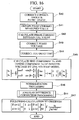
FIG. 3 is a flowchart of operations of the motor control apparatus in FIG. 1;
FIG. 4 is a flowchart of operations of a control apparatus for a brushless DC motor according to a second variation of the first embodiment;
FIG. 5 is a flowchart of an angular difference correction processing in FIG. 4;
FIG. 6 is a graph of an example of variations of an actual angular error and an angular difference approximate value according to the second variation of the first embodiment;
FIG. 7 is a flowchart of an angular difference correction processing according to a third variation of the first embodiment;
FIG. 8 is a graph of an example of variations of an actual angular error and an angular difference approximate value according to the third variation of the first embodiment;
FIG. 9 shows a configuration of a control apparatus for a brushless DC motor according to a fourth variation of the first embodiment;
FIG. 10 shows a configuration of a control apparatus for a brushless DC motor according to a second embodiment;
FIG. 11 is a graph of an example of time variations of phase voltage command values V1, V2 and V3 and current measured values I0, I1, I2 and I3 that form time-series data;
FIG. 12 shows configuration of a PWM inverter included in a PDU in FIG. 10;
FIG. 13 shows commutation of a current that occurs in a dead time of the PWM inverter;
FIG. 14 is a flowchart of operations of the motor control apparatus in FIG. 10;
FIG. 15A is a graph of time variations of an estimated rotation angle θ^ estimated without correction of the dead time and an actual rotation angle θ;
FIG. 15B is a graph of time variations of an estimated rotation angle θ^ estimated with the correction of the dead time and an actual rotation angle θ;
FIG. 16 is a flowchart of operations of a control apparatus for a brushless DC motor according to a second variation of the second embodiment;
FIG. 17 shows a configuration of a control apparatus for a brushless DC motor according to a fourth variation of the second embodiment;
FIG. 18A schematically shows a motor according to a fifth variation of the second embodiment; and
FIG. 18B shows a magnetic circuit of the motor in FIG. 18A.
DETAILED DESCRIPTION OF THE PREFERRED EMBODIMENTS
Now, a first embodiment of a control apparatus for a brushless DC motor according to the invention will be described with reference to the accompanying drawings.
The control apparatus for a brushless DC motor 10 (hereinafter simply referred to as the motor control apparatus 10) according to the first embodiment drives and controls a brushless DC motor 12 (hereinafter simply referred to as the motor 12) included in, for example, a hybrid vehicle as a drive source together with an internal combustion engine 11. The motor 12 includes a rotor (not shown) connected in series to the internal combustion engine 11 and having a permanent magnet used as a field, and a stator (not shown) that generates a rotating magnetic field for rotating the rotor.
The motor control apparatus 10 includes, as shown in FIG. 1, a power drive unit (PDU) 13, a battery 14, a control unit 15, an angular error calculation unit 16, and an observer 17.
In the motor control apparatus 10, a drive and a regenerative operation of the motor 12 having a plurality of phases (for example, three phases: a U-phase; a V-phase; and a W-phase) are performed by the power drive unit (PDU) 13 that receives a control command output from the control unit 15.
The PDU 13 includes, for example, a PWM inverter by pulse width modulation (PWM) having a bridge circuit with a plurality of switching elements of a transistor connected by bridges, and a high voltage battery 14 for supplying and receiving electric energy to and from the motor 12 is connected to the PDU 13.
When driving the motor 12, the PDU 13 converts DC power supplied from the battery 14 to three-phase AC power based on command values (a U-phase AC voltage command value Vu, a V-phase AC voltage command value Vv, a W-phase AC voltage command value Vw) output from the control unit 15, performs successive commutation of current to a stator winding of the three-phase motor 12, and thus outputs a U-phase current Iu, a V-phase current Iv, and a W-phase current Iw corresponding to the voltage command values Vu, Vv and Vw to the phases of the motor 12.
The control unit 15 performs feedback control of current on d-q coordinates that form rotating orthogonal coordinates, calculates the voltage command values Vu, Vv and Vw based on an Id command and an Iq command, inputs pulse width modulation signals to the PDU 13, and controls so that each difference becomes zero between a d-axis current Id and a q-axis current Iq and the Id command and the Iq command, respectively, obtained by converting the phase currents Iu, Iv and Iw actually supplied from the PDU 13 to the motor 12 on the d-q coordinates.
The control unit 15 includes, for example, a current command input unit 21, subtracters 22 and 23, a current feedback control unit 24, a dq-three phase conversion unit 25, and a three phase-dq conversion unit 26.
The current command input unit 21 calculates a current command for specifying the phase currents Iu, Iv and Iw supplied from the PDU 13 to the motor 12 based on a torque command value for causing the motor 12 to generate a torque value required according to the amount of acceleration operation relating to driver's depression of an accelerator pedal and the revolution speed of the motor 12, and the current command is output to the subtracters 22 and 23 as the Id command and the Iq command on the rotating orthogonal coordinates.
The d-q coordinates that form the rotating orthogonal coordinates sets, for example, a direction of a magnetic flux of a field pole by the permanent magnet of the rotor in a d-axis (a field axis) and sets a direction orthogonal to the d-axis in a q-axis (a torque axis), and rotates at an electrical angular velocity ω (hereinafter simply referred to as the rotational angular velocity ω) in synchrony with the rotor (not shown) of the motor 12. Thus, the Id command and the Iq command that are DC signals are provided as current commands to AC signals supplied from the PDU 13 to the phases of the motor 12
The subtracter 22 calculates a difference ΔId between the Id command and the d-axis current Id, and the subtracter 23 calculates a difference ΔIq between the Iq command and the q-axis current Iq. The differences ΔId and ΔIq output from the subtracters 22 and 23 are input to the current feedback control unit 24.
The current feedback control unit 24 controls and amplifies the difference ΔId to calculate a d-axis voltage command value Vd, and controls and amplifies the difference ΔIq to calculate a q-axis voltage command value Vq by a PI (proportional plus integral) action. The d-axis voltage command value Vd and the q-axis voltage command value Vq output from the current feedback control unit 24 are input to the dq-three phase conversion unit 25.
The dq-three phase conversion unit 25 uses an estimated rotation angle θ^ with respect to a rotation angle of the rotor input from a below described observer 17 to convert the d-axis voltage command value Vd and the q-axis voltage command value Vq on the d-q coordinates to a U-phase AC voltage command value Vu, a V-phase AC voltage command value Vv, and W-phase AC voltage command value Vw on three-phase AC coordinates that are static coordinates.
The voltage command values Vu, Vv and Vw output from the dq-three phase conversion unit 25 are input to the PDU 13 as switching commands (for example, pulse width modulation signals) for turning on/off the switching elements of the PDU 13.
The three phase-dq conversion unit 26 uses the estimated rotation angle θ^ with respect to the rotation angle of the rotor input from the below described observer 17 to convert the phase currents Iu, Iv and Iw on the static coordinates to the d-axis current Id and the q-axis current Iq on the rotating coordinates by rotational phases of the motor 12, that is, the d-q coordinates. Thus, measured values (for example, a U-phase current Iu and a W-phase current Iw) output from at least two phase current detectors 27 and 27 for detecting the phase currents Iu, Iv and Iw supplied to the stator windings of the phases of the motor 12 are input to the three phase-dq conversion unit 26. Then, the d-axis current Id and the q-axis current Iq output from the three phase-dq conversion unit 26 are output to the subtracters 22 and 23.
The angular error calculation unit 16 uses the fact that an angular difference θe can be approximated by a sine value sin θe (θe≈sin θe) when the angular difference θe (=θ−θ^) between the estimated rotation angle θ^ with respect to the rotation angle of the rotor and an actual rotation angle θ is relatively small to calculate the angular difference θe based on the sine value sin θe and a cosine value cos θe of the angular difference θe included in a circuit equation by, for example, a d-q axes calculation model, and output the angular difference θe to the observer 17.
The angular error calculation unit 16 includes, for example, a model calculation unit 31, an angular velocity state function calculation unit 32, and a normalization unit 33.
The model calculation unit 31 calculates a sine component Vs and a cosine component Vc of an induced voltage constituted by the sine value sin θe and the cosine value cos θe of the angular difference θe by a circuit equation on the d-q coordinates expressed as in Formula (3), based on the d-axis voltage command value Vd and the q-axis voltage command value Vq output from the current feedback control unit 24 and the d-axis current Id and the q-axis current Iq output from the three phase-dq conversion unit 26. In Formula (3), ω is a rotational angular velocity of the rotor, Ke is an induced voltage constant, r is a phase resistance, and L is an inductance component value.
[ Vs Vc ] ω Ke [ - sin θ e cos θ e ] = [ Vd Vq ] - [ r - ω L ω L r ] [ Id Iq ] ( 3 )
The angular velocity state function calculation unit 32 calculates, as expressed in Formula (4), a value (ωKe) obtained by multiplying the rotational angular velocity ω by the induced voltage constant Ke as a state function in proportion to the rotational angular velocity ω used in a below described normalization processing in the normalization unit 33, based on the sine component Vs and the cosine component Vc of the induced voltage calculated in the model calculation unit 31, and outputs the value to the normalization unit 33.
√{square root over (Vc 2 +Vs 2)}=ωKe  (4)
The normalization unit 33 calculates an angular difference approximate value (−Vs/(Vs2+Vc2)½≈θe) approximated by the angular difference θe by dividing the sine component Vs of the induced voltage calculated in the model calculation unit 31 by the state function (for example, ωKe) in proportion to the rotational angular velocity ω calculated in the angular velocity state function calculation unit 32, and inputs the value to the observer 17.
Specifically, if an angular difference estimated value θes is set as a value obtained by multiplying the angular difference θe by the rotational angular velocity ω and the induced voltage constant Ke, the angular difference estimated value θes is expressed as in Formula (5) so that the sine value sin θe is approximated by the angular difference θe (θe≈sin θe) in the sine component Vs of the induced voltage in Formula (3), and that voltage drop by the phase resistance r is ignored.
θ es = - ω Ke θ e - ω Ke sin θ e = Vd - rId + ω Llq Vd + ω LIq ( 5 )
In Formula (5), if there is an error ΔL, for example, in the inductance component value L, the angular difference estimated value θes is expressed as in Formula (6), and even if the angular difference θe is constant, the error increases in proportion to the rotational angular velocity ω.
Specifically, in Formula (6), the term including the error ΔL (ωLIq) indicates an error in the angular difference estimated value θes when the angular difference θe is zero, and increases in proportion to the rotational angular velocity ω. Thus, as shown in FIG. 2, in a relatively high rotational state of the motor 12 (for example, the dotted line H in FIG. 2), the error in the angular difference estimated value θes increases more than in a relatively low rotational state of the motor 12 (for example, the solid line L in FIG. 2).
θ es = Vd + ω ( L + Δ L ) Iq = - ω Ke sin θ e + ωΔ LIq - ω Ke θ + ωΔ LIq ( 6 )
When the angular difference estimated value θes by Formula (6) is divided by a value ωK (K is any constant) in proportion to the rotational angular velocity ω, the error in the angular difference estimated value θes becomes independent of the rotational angular velocity ω as shown in Formula (7).
θ es ω K = ω Ke sin θ e + ω Δ LI ω K Ke K θ e + Δ LI K ( 7 )
Thus, the observer 17 sets the value (Vs/(Vs2+Vc2)½) obtained by dividing the sine component Vs of the induced voltage approximated by the angular difference estimated value θes as expressed in Formula (5) by the state function (for example, ωKe) in proportion to the rotational angular velocity ω calculated in the angular velocity state function calculation unit 32 as expressed in Formula (4), that is, the angular difference approximate value (−Vs/(Vs2+Vc2)½≈θe) approximated by the angular difference θe, as an input value to a following calculation processing. Then, the observer 17 performs the following calculation processing so as to converge the input value (that is, the angular difference θe) to zero as expressed in Formula (8), successively updates the estimated rotation angle θ^ for calculation, and outputs a convergence value of the estimated rotation angle θ^ to the dq-three phase conversion unit 25 and the three phase-dq conversion unit 26 of the control unit 15.
In Formula (8), n is any counting number indicating the number of performance of the following calculation processing repeated at a predetermined time interval Δt, K1 is a control gain (feedback gain) relating to the estimated rotation angle θ^, K2 is a control gain (feedback gain) relating to a rotational angular velocity estimated value ω^, and K˜ is an appropriate proportional coefficient including positive and negative signs.
In Formula (8), “offset” is a rotation angle of the rotor set in the relatively low rotational state of the motor 12 or in calculation of the actual rotation angle θ.
[ θ ^ ( n + 1 ) ω ^ ( n + 1 ) ] = [ 1 Δ t 0 1 ] [ θ ^ ( n ) ω ^ ( n ) ] + [ K1 K2 ] K ~ Vs Vs 2 + Vc 2 [ 1 Δ t 0 1 ] [ θ ^ ( n ) ω ^ ( n ) ] + [ K1 K2 ] K ~ ( θ e ( n ) + offset ) , ( θ e ( n ) 0 ( 8 )
The motor control apparatus 10 according to the first embodiment has the above described configuration, and now, operations of the motor control apparatus 10, more particularly, a calculation processing of the estimated rotation angle θ^ in sensorless control by the d-q axes calculation model will be described with reference to the accompanying drawings.
First, in Step S01 in FIG. 3, detection results of the current values of the phase currents output from the phase current detectors 27 and 27, for example, the U-phase current Iu and the W-phase current Iw are obtained.
Next, in Step S02, based on the d-axis voltage command value Vd and the q-axis voltage command value Vq, and the d-axis current Id and the q-axis current Iq, the sine component Vs and the cosine component Vc of the induced voltage constituted by the sine value sin θe and the cosine value cos θe of the angular difference θe are calculated by the circuit equation on the d-q coordinates expressed as in Formula (3).
Then, in Step S03, based on the sine component Vs and the cosine component Vc of the induced voltage, as expressed in Formula (4), the state function (ωKe) in proportion to the rotational angular velocity ω is calculated, and the sine component Vs of the induced voltage is divided by the state function (ωKe) to calculate the angular difference approximate value (−Vs/(Vs2+Vc2)½≈θe).
Next, in Step S04, as expressed in Formula (8), the angular difference approximate value (−Vs/(Vs2+Vc2)½≈θe) is set as the input value to the following calculation processing, the following calculation processing is performed so as to converge the input value (that is, the angular difference θe) to zero, and thus the estimated rotation angle θ^ and the rotational angular velocity estimated value ω are subsequently updated for calculation to finish the series of processings.
As described above, according to the control apparatus for a brushless DC motor 10 of the first embodiment, the angular difference approximate value (−Vs/(Vs2+Vc2)½≈θe) obtained by normalization by the rotational angular velocity ω is set as the input value to the following calculation processing in the observer 17, thus improving calculation accuracy of the estimated rotation angle θ^, compared to the case where an angular difference estimated value θes that is not normalized by a rotational angular velocity ωis set as an input value to a following calculation processing to calculate an estimated rotation angle θ^.
In the first embodiment, the angular difference approximate value (Vs/(Vs2+Vc2)½) obtained by dividing the sine component Vs of the induced voltage by the state function (for example, ωKe) in proportion to the rotational angular velocity c) is set as the input value to the following calculation processing to calculate the estimated rotation angle θ^ in the observer 17, but is not limited to this. In a first variation of the first embodiment, the angular difference approximate value (Vs/(Vs2+Vc2)½) may be further approximated according to the magnitude of absolute values of the sine component Vs and the cosine component Vc of the induced voltage as expressed in Formula (9), and the approximate value (for example, Vs/|Vs| or Vs/|Vc|) may be set as the input value to the following calculation processing to calculate the estimated rotation angle θ^.
In this case, an excessively long processing time can be prevented particularly by a calculation processing of a square root ((Vs2+Vc2)½) in the angular difference approximate value (Vs/(Vs2+Vc2)½) obtained by dividing the sine component Vs of the induced voltage by the state function (ωKe) in proportion to the rotational angular velocity ω.
Vs Vs 2 + Vc 2 { Vs Vs , ( WHEN Vs > Vc ) Vs Vc , ( WHEN Vc > Vs ) ( 9 )
In a second variation of the first embodiment, an angular difference correction processing for correcting the angular difference approximate value (−Vs/(Vs2+Vc2)½≈θe) set as the input value to the following calculation processing may be performed by correcting the sine component Vs of the induced voltage according to the positive or negative sign of the cosine component Vc of the induced voltage.
In the second variation of the first embodiment, as shown in FIG. 4, after the normalization processing in Step S03, the process goes to Step 11 to perform a below described angular difference correction processing, and then perform the following calculation processing in Step S04.
In the angular difference correction processing in Step S11, first in Step 21 in FIG. 5, it is determined whether the cosine component Vc of the induced voltage is less than zero.
When it is determined to be “YES”, that is, when the sign of the cosine component Vc of the induced voltage is positive, the process goes to Step S22, and the angular difference approximate value (−Vs/(Vs2+Vc2)½≈θe), that is, the angular difference θe set as the input value to the following calculation processing is set to Vs/Vc to finish the series of processings.
On the other hand, when it is determined to be “NO”, that is, when the sign of the cosine component Vc of the induced voltage is negative, the process goes to Step S23, and the angular difference approximate value (−Vs/(Vs2+Vc2)½≈θe), that is, the angular difference θe set as the input value to the following calculation processing is set to Vs/|Vs| to finish the series of processings.
Specifically, as shown in FIG. 6, in a range where an absolute value of an actual angular error, that is, an actual angular difference θe is π/2 or less, the angular difference θe can be approximated by the sine value sin θe (θe≈sin θe), and thus the sine value sin θe (=Vs/(Vs2+Vc2)½≈Vs/Vc) calculated based on the sine component Vs and the cosine component Vc of the induced voltage is set as the input value to the following calculation processing.
On the other hand, in a range where the absolute value of the actual angular error is more than π/2, the difference between the angular difference θe and the sine value sin θe is larger, and thus the angular difference θe is not approximated by the sine value sin θe, but 1 or −1 is set as the input value to the following calculation processing.
Thus, a following property in the following calculation processing in the observer 17 can be improved.
In a third variation of the first embodiment, an angular difference correction processing for correcting the angular difference approximate value (−Vs/(Vs2+Vc2)½≈θe) set as the input value to the following collection processing may be performed by correcting the sine component Vs of the induced voltage according to a magnitude relation of absolute values of the sine component Vs and the cosine component Vc of the induced voltage.
In the third variation of the first embodiment, as the angular difference correction processing in Step 11, first in Step 31 in FIG. 7, it is determined whether the cosine component Vc of the induced voltage is larger than the absolute value |Vs| of the sine component Vs of the induced voltage.
When it is determined to be “YES”, the process goes to Step S32, and the angular difference approximate value (−Vs/(Vs2+Vc2)½≈θe), that is, the angular difference θe set as the input value to the following calculation processing is set to Vs/Vc to finish the series of processings.
On the other hand, when it is determined to be “NO”, the process goes to Step S33, and the angular difference approximate value (−Vs/(Vs2+Vc2)½≈θe), that is, the angular difference θe set as the input value to the following calculation processing is set to Vs/|Vs| to finish the series of processings.
Specifically, as shown in FIG. 8, in a range where the absolute value of the actual angular error, that is, the actual angular difference θe is π/4 or less, the angular difference θe can be approximated by the sine value sin θe (θe≈sin θe), and thus the sine value sin θe (=Vs/(Vs2+Vc2)½≈Vs/Vc) calculated based on the sine component Vs and the cosine component Vc of the induced voltage is set as the input value to the following calculation processing.
On the other hand, in a range where the absolute value of the actual angular error is more than π/4, the difference between the angular difference θe and the sine value sin θe is larger, and thus the angular difference θe is not approximated by the sine value sin θe, and 1 or −1 is set as the input value to the following calculation processing.
Thus, setting the angle range where the angular difference θe is approximated by the sine value sin θe to be narrower than the second variation of the first embodiment further improves the following property in the following calculation in the observer 17.
In the first embodiment, as the normalization processing, the sine component Vs of the induced voltage calculated by the model calculation unit 31 is divided by the state function (for example, ωKe) in proportion to the rotational angular velocity ω calculated in the angular velocity state function calculation unit 32, but is not limited to this, as a fourth variation of the first embodiment in FIG. 8, the angular velocity state function calculation unit 32 may be omitted, an angular velocity calculation unit 36 may be provided that calculates the rotational angular velocity ω of the motor 12 based on the revolution speed of the engine Ne of the internal combustion engine 11 output from an engine revolution speed sensor 35, and the sine component Vs of the induced voltage may be divided by the rotational angular velocity ω as a normalization processing.
Specifically, in the fourth variation of the first embodiment, the motor 12 is connected in series to the internal combustion engine 11, and thus the rotational angular velocity ω of the motor 12 can be calculated from the revolution speed of the engine Ne in the angular velocity calculation unit 36, and the normalization unit 33 divides the sine component Vs of the induced voltage calculated in the model calculation unit 31 by the rotational angular velocity ω output from the angular velocity calculation unit 36 to calculate an approximate value (−Vs/ω≈Keθe) approximated by a value (Keθe) obtained by multiplying the angular difference θe by the induced voltage constant Ke, and input the value to the observer 17.
The observer 17 sets the approximate value (−Vs/ω≈Keθe) approximated by the value (Keθe) obtained by multiplying the angular difference θe by the induced voltage constant Ke as an input value to the following calculation processing, performs the following calculation processing so as to converge the input value to zero, thus successively updates the estimated rotation angle θ^ for calculation, and outputs a convergence value of the estimated rotation angle θ^ to the dq-three phase conversion unit 25 and the three phase-dq conversion unit 26 of the control unit 15.
Now, a second embodiment of a control apparatus for a brushless DC motor according to the invention will be described with reference to the accompanying drawings.
The control apparatus for a brushless DC motor 40 (hereinafter simply referred to as the motor control apparatus 40) according to the second embodiment includes, as shown in FIG. 10, a power drive unit (PDU) 13, a battery 14, a control unit 15, an observer 17, an angular error calculation unit 41, and a control angle correction unit 42.
The same parts as in the first embodiment are denoted by the same reference numerals, and descriptions thereof will be simplified or omitted.
The angular error calculation unit 41 uses the fact that an angular difference θe can be approximated by a sine value sin θe (θe≈sin θe) when an angular difference θe (=θ−θ^) between an estimated rotation angle θ^ with respect to a rotation angle of a rotor and an actual rotation angle θ is relatively small to calculate the angular difference θe based on the sine value sin θe and a cosine value cos θe of the angular difference θe included in a circuit equation by, for example, a line voltage model, and output the angular difference θe to the observer 17.
The angular error calculation unit 41 includes, for example, a model calculation unit 50, an angular velocity state function calculation unit 32, and a normalization unit 33.
The model calculation unit 50 calculates a sine component Vs and a cosine component Vc of an induced voltage constituted by the sine value sin θe and the cosine value cos θe of the angular difference θe by a circuit equation in the line voltage model expressed as in Formula (10), based on a U-phase AC voltage command value Vu, a V-phase AC voltage command value Vv, and a W-phase AC voltage command value Vw output from a dq-three phase conversion unit 25, and measured values (for example, a U-phase current Iu, and a W-phase current Iw) output from two phase current detectors 27 and 27.
In Formula (10), saliency of a motor 12 such that an inductance component value varies according to a rotation position of a stator winding is ignored, and Vuv is a line voltage between a U-phase and a V-phase (=Vu−Vv); Vwv, a line voltage between a W-phase and the V-phase (=Vw−Vv); r, a phase resistance; l, a self inductance; m, a mutual inductance; ω, a rotational angular velocity of the rotor; and Ke, an induced voltage constant.
[ Vu - Vv Vw - Vv ] = [ Vuv Vwv ] = r [ 2 1 1 2 ] [ Iu Iw ] + ( I - m ) [ 2 1 1 2 ] t [ Iu Iw ] + ω Ke [ 3 sin ( θ + π 6 ) 3 cos θ ] ( I - m ) [ 2 1 1 2 ] t [ Iu Iw ] + ω Ke [ 3 sin ( θ + π 6 ) 3 cos θ ] ( 10 )
The angular velocity state function calculation unit 32 calculates, as expressed in Formula (4), a value (ωKe) obtained by multiplying the rotational angular velocity ω by the induced voltage constant Ke as a state function in proportion to the rotational angular velocity ω, based on the sine component Vs and the cosine component Vc of the induced voltage calculated in the model calculation unit 50, and outputs the value to the normalization unit 33. The normalization unit 33 calculates an angular difference approximate value (−Vs/(Vs2+Vc2)½≈θe) approximated by the angular difference θe by dividing the sine component Vs of the induced voltage calculated in the model calculation unit 50 by the state function (for example, ωKe) in proportion to the rotational angular velocity ω calculated in the angular velocity state function calculation unit 32, and inputs the value to the observer 17.
The model calculation unit 50 includes, for example, a coefficient acting unit 51, a phase current differential value calculation unit 52, a phase voltage correction unit 53, and a dead time correction unit 54.
The coefficient acting unit 51 causes, based on Formula (10), a matrix A including a predetermined estimated rotation angle θ^ to act from the left as expressed in Formulas (11) and (12) with respect to an induced voltage component obtained by subtracting voltage drop relating to the phase resistance r and voltage drop relating to the self inductance l and the mutual inductance m from the line voltages Vuv and Vwv.
Specifically, the model calculation unit 50 calculates the sine component Vs and the cosine component Vc of the induced voltage as values in proportion to the sine value sin θe and the cosine value cos θe of the angular difference θe based on Formulas (11) and (12).
A = 2 3 [ cos θ ^ - sin ( θ ^ + π 6 ) sin θ ^ cos ( θ ^ + π 6 ) ] ( 11 ) A { [ Vuv Vwv ] - r [ 2 1 1 2 ] [ Iu Iw ] - ( I - m ) [ 2 1 1 2 ] t [ Iu Iw ] } = 2 3 [ cos θ ^ - sin ( θ ^ + π 6 ) sin θ ^ cos ( θ ^ + π 6 ) ] { [ Vuv Vwv ] - r [ 2 1 1 2 ] [ Iu Iw ] - ( I - m ) [ 2 1 1 2 ] t [ Iu Iw ] } 2 3 [ cos θ ^ - sin ( θ ^ + π 6 ) sin θ ^ cos ( θ ^ + π 6 ) ] { [ Vuv Vwv ] - ( I - m ) [ 2 1 1 2 ] t [ Iu Iw ] } = 2 3 [ cos θ ^ - sin ( θ ^ + π 6 ) sin θ ^ cos ( θ ^ + π 6 ) ] [ ω Ke 3 sin ( θ ^ + θ e + π 6 ) ω Ke 3 cos ( θ ^ + θ e ) ] = ω Ke [ sin θ e cos θ e ] [ Vs Vc ] ( 12 )
The phase current differential value calculation unit 52 calculates current differential values of the phase currents Iu and Iw included in the term of the voltage drop relating to the self inductance l and the mutual inductance m in Formula (12).
The phase current differential value calculation unit 52 sets a measured value of a current value Im (a current measured value) of a phase current output from the phase current detector 27 at a predetermined time interval Δt as time-series data, and calculates a time variation of an average current measured value by a filtering processing such as a least squares method or a moving average value calculation processing, based on four current measured values including a current measured value I0 at the present time t0, and at least two current measured values at past times, for example, a current measured value I1 at a time t1 (=t0−Δt); a current measured value I2 at a time t2(=t1−Δt=t0−2Δt); and a current measured value I3 at a time t3(=t2−Δt=t0−3Δt).
The time variation ΔI of the average current measured value at the predetermined time interval Δt obtained by the least squares method with respect to the current measured values I1, I1, I2 and I3 at the four times t0, t1, t2 and t3 is, as shown in FIG. 11, a value at a past time (t1+t2)/2 from the present time t0 by a time delay Td (=coefficient kd×predetermined time interval Δt, for example, kd=1.5). In FIG. 11, L is an approximate line indicating the time variation of the current measured value obtained by the least squares method.
The time variation ΔI and the current measured value Im corresponding to the time variation ΔI, that is, the current measured value Im at the time (t1+t2)/2 are expressed as in Formula (13) by the current measured values I0, I1, I2 and I3, and Formula (13) is modified as in Formula (14).
Specifically, the phase current differential value calculation unit 52 calculates the time variation ΔI of the average current measured value at the predetermined time interval Δt by Formula (14), and sets a time variation of the current measured value per unit time ΔI/Δt obtained by dividing the time variation ΔI by the predetermined time interval Δt as a current differential value of the phase current.
[ I0 I1 I2 I3 ] = [ 1.5 1 0.5 1 - 0.5 1 - 1.5 1 ] [ Δ I I m ] ( 13 ) [ Δ I I m ] = [ 0.3 0.1 - 0.1 - 0.3 0.25 0.25 0.25 0.25 ] [ I0 I1 I2 I3 ] ( 14 )
The phase voltage correction unit 53 corrects the voltage command values Vu, Vw and Vv for calculating the line voltage (for example, the line voltages Vuv and Vwv) according to the filtering processing in the phase current differential value calculation unit 52.
Specifically, corresponding to the fact that the time variation ΔI of the current measured value calculated in the phase current differential value calculation unit 52 is the value at the past time (t1+t2)/2, the phase voltage correction unit 53 sets a phase voltage command value at the time (t1+t2)/2 (for example, the phase voltage command value V1 in FIG. 11) as the voltage command values Vu, Vw and Vv for calculating the line voltage (for example, the line voltages Vuv and Vwv).
Alternatively, corresponding to the fact that the time variation ΔI of the current measured value is the average value at the past time (t1+t2)/2, the phase voltage correction unit 53 performs a filtering processing such as a least squares method or a moving average calculation processing with respect to the phase voltage command value V0 from the time t0 to the time t1, the phase voltage command value V1 from the time t1 to the time t2, the phase voltage command value V2 from the time t2 to the time t3, calculates an average phase voltage command value at the past time (t1+t2)/2 (for example, a moving average value (V0+V1+V2)/3), and sets the command value as the voltage command values Vu, Vw and Vv for calculating the line voltage (for example, the line voltages Vuv and Vwv).
A dead time correction unit 54 corrects the voltage command values Vu, Vw and Vv for calculating the line voltage (for example, the line voltages Vuv and Vwv) according to a dead time of a PWM inverter by pulse width modulation (PWM) included in the PDU 13 and polarities of the phase currents Iu, Iv and Iw supplied from the PDU 13 to the motor 12.
Specifically, as show in FIG. 12, the PWM inverter 13A in the PDU 13 includes a bridge circuit 13 a with a plurality of switching elements connected by bridges, and a smoothing capacitor C, and the bridge circuit 13 a includes transistors TU1, TU2, TV1, TV2, TW1 and TW2 that are a plurality of switching elements.
Then, between a collector and an emitter of the transistors TU1, TU2, TV1, TV2, TW1 and TW2, diodes DU1, DU2, DV1, DV2, DW1 and DW2 are placed, an anode of each of the diodes DU1, DU2, DV1, DV2, DW1 and DW2 is connected to the emitter of each of the transistors TU1, TU2, TV1, TV2, TW1 and TW2, and a cathode of each of the diodes DU1, DU2, DV1, DV2, DW1 and DW2 is connected to each collector.
The collectors of the transistors TU1, TV1 and TW1 are connected to a positive pole terminal of the battery 14. The emitter of the transistor TU1 is connected to the collector of the transistor TU2, the emitter of the transistor TV1 is connected to the collector of the transistor TV2, and the emitter of the transistor TW1 is connected to the collector of the transistor TW2. The emitters of the transistors TU2, TV2 and TW2 are connected to a negative pole terminal of the battery 14.
A U-phase stator winding of the motor 12 is connected to the emitter of the transistor TU1 and the collector of the transistor TU2, a V-phase stator winding of the motor 12 is connected to the emitter of the transistor TV1 and the collector of the transistor TV2, and a W-phase stator winding of the motor 12 is connected to the emitter of the transistor TW1 and the collector of the transistor TW2.
Then, the smoothing capacitor C is connected between the positive pole terminal and the negative pole terminal of the battery 14.
The PWM inverter 13A switches on/off the pairs of transistors TU1 and TU2, transistors TV1 and TV2, and transistors TW1 and TW2 for each phase to pass an AC phase current to the stator winding of each phase. In order to prevent a phase short-circuit in the PWM inverter 13A, a dead time is provided for setting both of the pairs of transistors TU1 and TU2, transistors TV1 and TV2, and transistors TW1 and TW2 for each phase to an off state.
In the dead time, the current is commutated to either of the pairs of diodes DU1 and DU2, diodes DV1 and DV2, and diodes DW1 and DW2 for each phase according to the polarity of the phase current to vary an output voltage of the PWM inverter 13A.
For example, as shown in FIG. 13, if both transistors TU1 and TU2 are set to the off state when the polarity of the phase current is positive with respect to the transistors TU1 and TU2 and the diodes DU1 and DU2 of the U-phase (that is, when the U-phase current Iu passes in a direction from the PWM inverter 13A to the motor 12), the current is commutated to the diode DU2 connected to the negative terminal of the battery 14 to reduce the output voltage. On the other hand, if the both transistors TU1 and TU2 are set to the off state when the polarity of the phase current is negative (that is, when the U-phase current Iu passes in a direction from the motor 12 to the PWM inverter 13A), the current is commutated to the diode DU1 connected to the positive terminal of the battery 14 to increase the output voltage.
Thus, an actual output voltage (an actual voltage) VR of each phase of the PWM inverter 13A is expressed as in Formula (15) according to a phase voltage command value Vm, a cycle T of pulse width modulation (PWM), a dead time TD, and a voltage between terminals VB of the battery 14.
The dead time correction unit 54 calculates the actual voltage VR based on Formula (15), and sets the actual voltage as the voltage command values Vu, Vw and Vv for calculating the line voltage (for example, the line voltages Vuv and Vwv).
V R = Vm - T D T V B , ( PHASE CURRENT > 0 ) V R = Vm + T D T V B , ( PHASE CURRENT < 0 ) } ( 15 )
The control angle correction unit 42 corrects a control angle θc used in a current feedback control unit 24 corresponding to the filtering processing in the phase current differential value calculation unit 52.
Specifically, corresponding to the fact that the time variation ΔI of the current measured value calculated in the phase current differential value calculation unit 52 is the value at the past time (t1+t2)/2, the control angle correction unit 42 calculates, as expressed in Formula (16), a control angle θc(n) at the present time t0 with the time delay Td (=coefficient kd×predetermined time interval Δt, for example, kd=1.5) corrected, based on an estimated rotation angle θ^(n) and a rotational angular velocity estimated value ω^(n) calculated in the former following calculation processing in the observer 17, and outputs the control angle to the current feedback control unit 24.
Thus, in the second embodiment, the current feedback control unit 24 controls and amplifies a difference ΔId to calculate a d-axis voltage command value Vd, and controls and amplifies a difference ΔIq to calculate a q-axis voltage command value Vq by a PI (proportional plus integral) action according to the control angle θc.
θc=kd·Δt·ω^(n)  (16)
The motor control apparatus 40 according to the second embodiment has the above described configuration, and now, operations of the motor control apparatus 40, more particularly, a calculation processing of the estimated rotation angle θ^ in sensorless control by the line voltage model will be described with reference to the accompanying drawings.
First, in Step S40 in FIG. 14, the control angle θc(n) at the present time t0 with the time delay Td (=coefficient kd×predetermined time interval Δt, for example, kd=1.5) corrected according to the filtering processing in the phase current differential value calculation unit 52 is calculated based on the estimated rotation angle θ^(n) and the rotational angular velocity estimated value ω^(n) calculated in the former following calculation processing in the observer 17 to output the control angle to the current feedback control unit 24.
Next, in Step S41, detection results of the current values of the phase currents output from the phase current detectors 27 and 27, for example, the U-phase current Iu and the W-phase current Iw are obtained.
Next, in Step S42, the current measured value output from the phase current detector 27 at the predetermined time interval Δt with respect to the phase currents Iu and Iw is set as time-series data, the time variation ΔI of the average current measured value at the predetermined time interval Δt is calculated by the least square method based on the current measured value I0 at the present time t0 and the current measured values I1, I2 and I3 at the past times t1, t2 and t3, and the value obtained by dividing the time variation ΔI of the calculated current measured value by the predetermined time interval Δt is set as the current differential value of the phase current.
Then, in Step S43, according to the filtering processing in the phase current differential value calculation unit 52, the phase voltage command value output from the dq-three phase conversion unit 25 to the voltage command values Vu, Vw and Vv for calculating the line voltage (for example, the line voltages Vuv and Vwv) at the predetermined time interval Δt is set as time-series data, and the value (V0+V1+V2)/3) obtained by the moving average value calculation processing with respect to the phase voltage command values V0, V1 and V2 are newly set as the voltage command values Vu, Vw and Vv for calculating the line voltage (for example, the line voltages Vuv and Vwv).
Then, in Step S44, the actual voltage VR is calculated based on Formula (15) with respect to the voltage command values Vu, Vw and Vv for calculating the line voltage (for example, the line voltages Vuv and Vwv), and newly set as the voltage command values Vu, Vw and Vv for calculating the line voltage (for example, the line voltages Vuv and Vwv).
Then, in Step S45, the sine component Vs and the cosine component Vc of the induced voltage constituted by the sine value sin θe and the cosine value cos θe of the angular difference θe are calculated by the circuit equation by the line voltage model expressed in Formula (12), based on the current differential values of the phase currents Iu and Iw, the line voltages Vuv and Vwv calculated from the voltage command values Vu, Vw and Vv, the phase resistance r, the self inductance l, and the mutual inductance m.
Then, in Step S46, based on the sine component Vs and the cosine component Vc of the induced voltage, as expressed in Formula (4), the state function (for example, ωKe) in proportion to the rotational angular velocity ω is calculated, and the sine component Vs of the induced voltage is divided by the state function (for example, ωKe) to calculate the angular difference approximate value (−Vs/(Vs2+Vc2)½≈θe).
Next, in Step S47, as expressed in Formula (8), the angular difference approximate value (−Vs/(Vs2+Vc2)½≈θe) is set as the input value to the following calculation processing, and the following calculation processing is performed so as to converge the input value (that is, the angular difference θe) to zero, and thus the estimated rotation angle θ^ and the rotational angular velocity estimated value ω^ are subsequently updated for calculation to finish the series of processings.
As described above, according to the control apparatus for a brushless DC motor 40 of the second embodiment, the angular difference approximate value (−Vs/(Vs2+Vc2)½≈θe) obtained by normalization by the rotational angular velocity ω is set as the input value to the following calculation processing in the observer 17, thus improving calculation accuracy of the estimated rotation angle θ^, compared to the case where an angular difference estimated value θes that is not normalized by a rotational angular velocity ω is set as an input value to a following calculation processing to calculate an estimated rotation angle θ^.
Furthermore, calculating the sine component Vs and the cosine component Vc of the induced voltage constituted by the sine value sin θe and the cosine value cos θe of the angular difference θe based on the circuit equation by the line voltage model allows the estimated rotation angle θ^ to be estimated with high accuracy even if a current waveform and a voltage waveform are deformed from a sine wave or are not a sine wave.
The line voltage model allows the sine component Vs of the induced voltage to be calculated even if the rotational angular velocity ω of the rotor is unknown in the first processing, unlike calculation of the sine component Vs of the induced voltage based on the d-q axes calculation model.
Correcting the voltage command values Vu, Vw and Vv for calculating the line voltage and correcting the control angle θc used in the current feedback control unit 24, according to the filtering processing for calculating the current differential value of the phase current with the current measured value output from the phase current detector 27 set as the time-series data, allow the estimated rotation angle θ^ to be estimated with high accuracy.
Furthermore, correcting the dead time of the PWM inverter 13A included in the PDU 13 with respect to the voltage command values Vu, Vw and Vv for calculating the line voltage (for example, the line voltages Vuv and Vwv) improves estimation accuracy of the estimated rotation angle θ^.
Specifically, if the output voltage of the PWM inverter 13A varies by the dead time of the PWM inverter 13A, the phase of the induced voltage is shifted, and thus a large time lag relative to the time variation of the actual rotation angle θ occurs in the time variation of the estimated rotation angle θ^ estimated without correction of the dead time in FIG. 15A. On the other hand, the time variation of the estimated rotation angle θ^ estimated with the correction of the dead time in FIG. 15B displays substantially the same variation as the time variation of the actual rotation angle θ to improve the estimation accuracy of the estimated rotation angle θ^.
In the first variation of the second embodiment, the angular difference approximate value (Vs/(Vs2+Vc2)½) may be approximated according to the magnitude of absolute values of the sine component Vs and the cosine component Vc of the induced voltage as in Formula (9), and the approximate value (for example, Vs/|Vs| or Vs/|Vc|) may be set as the input value to the following calculation processing to calculate the estimated rotation angle θ^.
In a second variation of the second embodiment, an angular difference correction processing for correcting the angular difference approximate value (−Vs/(Vs2+Vc2)½≈θe) set as the input value to the following calculation processing may be performed by correcting the sine component Vs of the induced voltage according to the positive or negative sign of the cosine component Vc of the induced voltage.
In the second variation of the second embodiment, as shown in FIG. 16, after the normalization processing in Step S46, the process goes to Step 11 to perform the angular difference correction processing from Step 21 to Step 23, and then perform the following calculation processing in Step S47.
In a third variation of the second embodiment, an angular difference correction processing for correcting the angular difference approximate value (−Vs/(Vs2+Vc2)½≈θe) set as the input value to the following calculation processing may be performed by correcting the sine component Vs of the induced voltage according to a magnitude relation of absolute values of the sine component Vs and the cosine component Vc of the induced voltage.
In the third variation of the second embodiment, after the normalization processing in Step S46, the process goes to Step 11 to perform the angular difference correction processing from Step 31 to Step S33, and then perform the following calculation processing in Step S47.
In a fourth variation of the second embodiment, as the control apparatus for a brushless DC motor 40 in FIG. 17, the angular velocity state function calculation unit 32 may be omitted, an angular velocity calculation unit 36 may be provided that calculates the rotational angular velocity ω of the motor 12 based on the revolution speed of the engine Ne of the internal combustion engine 11 output from an engine revolution speed sensor 35, and the sine component Vs of the induced voltage may be divided by the rotational angular velocity ω as a normalization processing.
Specifically, in the fourth variation of the second embodiment, the motor 12 is connected in series to the internal combustion engine 11, and thus the rotational angular velocity ω of the motor 12 can be calculated from the revolution speed of the engine Ne in the angular velocity calculation unit 36, and the normalization unit 33 divides the sine component Vs of the induced voltage calculated in the model calculation unit 50 by the rotational angular velocity ω output from the angular velocity calculation unit 36 to calculate an approximate value (−Vs/ω≈Keθe) approximated by a value (Keθe) obtained by multiplying the angular difference θe by the induced voltage constant Ke, and input the value to the observer 17.
The observer 17 sets the approximate value (−Vs/ω≈Keθe) approximated by the value (Keθe) obtained by multiplying the angular difference θe by the induced voltage constant Ke as an input value to the following calculation processing, performs the following calculation processing so as to converge the input value to zero, thus successively updates the estimated rotation angle θ^ for calculation, and outputs a convergence value of the estimated rotation angle θ^ to the dq-three phase conversion unit 25 and the three phase-dq conversion unit 26 of the control unit 15.
In the second embodiment, the line voltage model that ignores saliency of the motor 12 is used as expressed in Formula (10), but as a fifth variation of the second embodiment in FIGS. 18A and 18B, the motor 12 may have saliency so that the inductance component value varies according to the rotation position of the stator winding.
In the fifth variation of the second embodiment, by postulating that the saliency of the motor 12 results from a magnetic substance P formed to be long along a diameter of the rotor as in FIG. 18A, a magnetic reluctance of an air gap of the motor 12 varies twice per cycle of the rotation of the rotor, that is, in a half cycle of the rotation of the rotor.
If the variation of the magnetic reluctance is set as a unit cosine wave, and an average value is set to 0.5, magnetic reluctances Ru, Rv and Rw of the phases are expressed as in Formula (17), for example, in a magnetic circuit in FIG. 18B.
Ru = 1 - cos 2 θ Rv = 1 - cos ( 2 θ + 2 π 3 ) Rw = 1 - cos ( 2 θ - 2 π 3 ) } ( 17 )
A magnetic reluctance Rg of the air gap viewed from the U-phase is expressed as in Formula (18).
Rg = Ru + Rv · Rw Rv + Rw = 1 - cos 2 θ + 1 - cos ( 2 θ - 2 3 π ) - cos ( 2 θ + 2 3 π ) + cos ( 2 θ - 2 3 π ) cos ( 2 θ + 2 3 π ) 2 - cos ( 2 θ - 2 3 π ) - cos ( 2 θ + 2 3 π ) = 5 + cos 2 3 π 4 + 2 cos 2 θ ( 18 )
Thus, by postulating a unit winding for the stator winding, a U-phase inductance Lu is expressed as in Formula (19), and mutual inductances Mwv and Muv are expressed as in Formula (20).
Lu = 1 / Rg = 4 + 2 cos 2 θ 5 + cos 2 3 π ( 19 ) Muw = - Rw Rv + Rw Lu = - 1 - cos ( 2 θ + 2 3 π ) 2 - cos ( 2 θ - 2 3 π ) - cos ( 2 θ - 2 3 π ) × 4 + 2 cos 2 θ 5 + cos 2 3 π = - 2 - 2 cos ( 2 θ + 2 3 π ) 5 + cos 2 3 π Muv = - Rv Rv + Rw Lu = - 2 - 2 cos ( 2 θ - 2 3 π ) 5 + cos 2 3 π } ( 20 )
From Formulas (18) to (20), the self inductance and the mutual inductance of the motor 12 having the saliency are generally expressed as in Formula (21), and a voltage equation of the motor 12 is expressed as in Formula (22).
[ I - Δ cos 2 θ m - Δ cos ( 2 θ - 2 3 π ) m - Δ cos ( 2 θ + 2 3 π ) m - Δ cos ( 2 θ - 2 3 π ) I - Δ cos ( 2 θ + 2 3 π ) m - Δ cos 2 θ m - Δ cos ( 2 θ + 2 3 π ) m - Δ cos 2 θ I - Δ cos ( 2 θ - 2 3 π ) ] ( 21 ) [ Vu Vv Vw ] = r [ Iu Iv Iw ] + t [ I - Δ cos 2 θ m - Δ cos ( 2 θ - 2 3 π ) m - Δ cos ( 2 θ + 2 3 π ) m - Δ cos ( 2 θ - 2 3 π ) I - Δ cos ( 2 θ + 2 3 π ) m - Δ cos 2 θ m - Δ cos ( 2 θ + 2 3 π ) m - Δ cos 2 θ I - Δ cos ( 2 θ - 2 3 π ) ] [ Iu Iv Iw ] + ω K e [ sin ω t sin ( ω t - 2 3 π ) sin ( ω t - 4 3 π ) ] ( 22 )
Based on Formula (22), the circuit equation of the line voltage model is expressed as in Formula (23).
[ 1 - 1 0 0 - 1 1 ] [ Vu Vv Vw ] = [ Vu - Vv Vw - Vv ] [ 1 - 1 0 0 - 1 1 ] ( r [ Iu Iv Iw ] + t [ I - Δ cos 2 θ m - Δ cos ( 2 θ - 2 3 π ) m - Δ cos ( 2 θ + 2 3 π ) m - Δ cos ( 2 θ - 2 3 π ) I - Δ cos ( 2 θ + 2 3 π ) m - Δ cos 2 θ m - Δ cos ( 2 θ + 2 3 π ) m - Δ cos 2 θ I - Δ cos ( 2 θ - 2 3 π ) ] [ Iu Iv Iw ] + ω Ke [ sin ω t sin ( ω t - 2 3 π ) sin ( ω t - 4 3 π ) ] ) = r [ 2 1 1 2 ] [ Iu Iw ] + ( I - m ) [ 2 1 1 2 ] t [ Iu Iw ] + ω [ - 6 Δ sin ( 2 θ - 2 3 π ) 6 Δ sin ( 2 θ + 2 3 π ) 6 Δ sin ( 2 θ + 2 3 π ) - 6 Δ sin 2 θ ] [ Iu Iw ] + [ 3 Δ cos ( 2 θ - 2 3 π ) - 3 Δ cos ( 2 θ + 2 3 π ) - 3 Δ cos ( 2 θ + 2 3 π ) 3 Δ cos 2 θ ] t [ Iu Iw ] + ω Ke [ 3 sin ( θ + π 6 ) 3 cos θ ] ( 23 )
In Formula (23), if the phase currents Iu and Iw are sine waves and expressed as in Formula (24), the term including 2θ is expressed as in Formulas (25) and (26).
Thus, Formula (23) is expressed as in Formula (27).
[ Iu Iw ] = [ I sin ( θ + α ) I sin ( θ + α + 2 3 π ) ] ( 24 ) ω [ - 6 Δ sin ( 2 θ - 2 3 π ) 6 Δ sin ( 2 θ + 2 3 π ) 6 Δ sin ( 2 θ + 2 3 π ) - 6 Δ sin 2 θ ] [ Iu Iw ] = ω [ - 6 Δ sin ( 2 θ - 2 3 π ) 6 Δ sin ( 2 θ + 2 3 π ) 6 Δ sin ( 2 θ + 2 3 π ) - 6 Δ sin 2 θ ] [ sin ( θ + α ) I sin ( θ + α + 2 3 π ) ] = 3 ω Δ [ 3 cos ( θ - α + π 6 ) 3 sin ( θ - α ) ] ( 25 ) [ 3 Δ cos ( 2 θ - 2 3 π ) - 3 Δ cos ( 2 θ + 2 3 π ) 3 Δ cos ( 2 θ + 2 3 π ) 3 Δ cos 2 θ ] t [ Iu Iw ] = 3 ωΔ [ cos ( 2 θ - 2 3 π ) - cos ( 2 θ + 2 3 π ) - cos ( 2 θ + 2 3 π ) cos 2 θ ] [ cos ( θ + α ) cos ( θ + α + 2 3 π ) ] = 3 ω Δ 2 [ - 3 cos ( θ - α + π 6 ) - 3 sin ( θ - α ) ] ( 26 ) [ Vu - Vv Vw - Vv ] = [ Vuv Vwv ] = r [ 2 1 1 2 ] [ Iu Iw ] + ( I - m ) [ 2 1 1 2 ] t [ Iu Iw ] + 3 ω Δ 2 [ 3 cos ( θ - α + π 6 ) 3 sin ( θ - α ) ] + ω Ke [ 3 sin ( θ + π 6 ) 3 cos θ ] ( 27 )
In Formula (27), the third term on the right side indicates a voltage by reluctance torque, and the voltage may be included in the induced voltage if the magnitude and the phase of the current are determined. Thus, if the induced voltage including the reluctance torque is defined as expressed in Formula (28), Formula (27) is expressed as in Formula (29) and similar to Formula (10), and thus the estimated rotation angle θ^ can be estimated by a processing similar to that when the saliency of the motor 12 is ignored as in the second embodiment.
In Formulas (28) and (29), Ke˜ is an induced voltage constant that varies according to a current value, and θ˜ is an actual rotation angle that varies according to the current value.
ω K ~ e [ 3 sin ( θ ~ + π 6 ) 3 cos θ ~ ] = 3 ω Δ 2 [ 3 cos ( θ - α + π 6 ) 3 sin ( θ - α ) ] + ω Ke [ 3 sin ( θ + π 6 ) 3 cos θ ] ( 28 ) [ Vu - Vv Vw - Vv ] = [ Vuv Vwv ] = r [ 2 1 1 2 ] [ Iu Iw ] + ( I - m ) [ 2 1 1 2 ] t [ Iu Iw ] + ω K ~ e [ 3 sin ( θ ~ + π 6 ) 3 cos θ ~ ] ( 29 )
In the fifth variation of the second embodiment, if the phase currents Iu and Uw are not sine waves and include harmonics, a processing unit having a low-pass property may be provided in the observer 17 or the like, and the estimated rotation angle θ^ can be estimated with high accuracy even with an influence of harmonics.
In the first and second embodiments, the observer 17 performs the following calculation processing based on Formula (8), but is not limited to this, and may perform the following calculation processing based on Formula (30).
[ θ ^ ( n + 1 ) ω ^ ( n + 1 ) ] = [ 1 Δ t 0 1 ] [ θ ^ ( n ) ω ^ ( n ) ] + [ K1 K2 ] K ~ 1 2 tan - 1 Vs Vc = [ 1 Δ t 0 1 ] [ θ ^ ( n ) ω ^ ( n ) ] + [ K1 K2 ] K ~ ( θ e ( n ) + offset ) ( 30 )
While preferred embodiments of the invention have been described and illustrated above, it should be understood that these are exemplary of the invention and are not to be considered as limiting. Additions, omissions, substitutions, and other modifications can be made without departing from the spirit or scope of the present invention. Accordingly, the invention is not to be considered as being limited by the foregoing description, and is only limited by the scope of the appended claims.

Claims (11)

1. A control apparatus for a brushless DC motor that rotatably drives the brushless DC motor including a rotor having a permanent magnet, and a stator having stator windings of a plurality of phases that generate a rotating magnetic field for rotating the rotor, by a current passage switching device constituted by a plurality of switching elements and performing successive commutation of current to the stator windings, the control apparatus comprising:
an angular error calculation device for calculating a sine value and a cosine value of an angular difference between an estimated rotation angle with respect to the rotation angle of the rotor and an actual rotation angle, based on a line voltage that is a difference between phase voltages of the plurality of phases on an input side of the stator winding and phase currents of the plurality of phases; and
an observer for calculating the rotation angle of the rotor based on the sine value and the cosine value of the angular difference.
2. The control apparatus for a brushless DC motor according to claim 1, wherein the angular error calculation device calculates a sine component and a cosine component of an induced voltage constituted by the sine value and the cosine value of the angular difference, and comprises:
an angular velocity state function calculation device for calculating a state function in proportion to an angular velocity of the rotor based on the sine component and the cosine component of the induced voltage; and
a normalization device for dividing the sine component of the induced voltage by the state function in proportion to the angular velocity of the rotor.
3. The control apparatus for a brushless DC motor according to claim 1, wherein the angular error calculation device calculates the sine component and the cosine component of the induced voltage constituted by the sine value and the cosine value of the angular difference, and comprises:
a revolution speed measuring device for measuring the revolution speed of the brushless DC motor;
an angular velocity calculation device for calculating the angular velocity of the rotor based on the revolution speed of the brushless DC motor; and
a normalization device for dividing the sine component of the induced voltage by the angular velocity of the rotor.
4. The control apparatus for a brushless DC motor according to claim 1, wherein the angular error calculation device calculates the sine component and the cosine component of the induced voltage constituted by the sine value and the cosine value of the angular difference, and comprises:
a coefficient acting device for causing a predetermined coefficient according to the estimated rotation angle to act on the sine component and the cosine component of the induced voltage; and
a phase current differential value calculation device for calculating a differential value of the phase current, and
the sine value and the cosine value of the angular difference is calculated based on Formula (1),
2 3 [ cos θ ^ - sin ( θ ^ + π 6 ) sin θ ^ cos ( θ ^ + π 6 ) ] { [ V 1 V 2 ] - r [ 2 1 1 2 ] [ I 1 I 2 ] - ( I - m ) [ 2 1 1 2 ] t [ I 1 I 2 ] } ω Ke [ sin θ e cos θ e ] [ Vs Vc ] ( 1 )
where r is a phase resistance; V1, a first line voltage; V2; a second line voltage; I1, a first phase current; I2, a second phase current; l, a self inductance; m, a mutual inductance; θ^, an estimated rotation angle; θe, an angular difference between the estimated rotation angle and an actual rotation angle; ω, a rotational angular velocity of the rotor; Ke, an induced voltage constant; Vs, a sine component of the induced voltage; and Vc; a cosine component of the induced voltage.
5. The control apparatus for a brushless DC motor according to claim 4, wherein the phase current differential value calculation device calculates, by a least squares method, variations of current measured values per unit time at past predetermined times with respect to at least three of the current measured values of the phase currents that form time-series data, and comprises:
a phase voltage correction device for correcting a time delay relating to the past predetermined times with respect to the phase voltages of the plurality of phases for calculating the line voltage; and
a control angle correction device for correcting a time delay relating to an appropriate past time with respect to a control angle relating to the rotation angle of the rotor used when the phase currents of the plurality of phases are converted to a d-axis current and a q-axis current on d-q coordinates that form rotating orthogonal coordinates, and feedback control is performed so that a difference between a command value and a measured value of each current on the d-q coordinates becomes zero.
6. The control apparatus for a brushless DC motor according to claim 1, wherein the current passage switching device includes a bridge circuit with the plurality of switching elements connected by bridges, and
the control apparatus further comprises a dead time correction device for correcting the phase voltages of the plurality of phases for calculating the line voltage, based on a dead time in which two of the switching elements connected in series for each phase in the bridge circuit are set to an off state, and polarities of the phase currents.
7. The control apparatus for a brushless DC motor according to claim 1, wherein the observer comprises an angular difference correction device for correcting the angular difference when the cosine value of the angular difference is negative.
8. The control apparatus for a brushless DC motor according to claim 1, wherein the observer comprises an angular difference correction device for correcting the angular difference according to a magnitude relation of absolute values of the sine value and the cosine value of the angular difference.
9. A control method for a brushless DC motor that rotatably drives the brushless DC motor including a rotor having a permanent magnet, and a stator having stator windings of a plurality of phases that generate a rotating magnetic field for rotating the rotor, the control method comprising the steps of:
rotating the DC motor by performing successive commutation of current to the stator windings;
calculating a sine value and a cosine value of an angular difference between an estimated rotation angle with respect to the rotation angle of the rotor and an actual rotation angle, based on a line voltage that is a difference between phase voltages of the plurality of phases on an input side of the stator winding and phase currents of the plurality of phases; and
calculating the rotation angle of the rotor based on the sine value and the cosine value of the angular difference.
10. The control method for a brushless DC motor according to claim 9, further comprising the steps of:
calculating a sine component and a cosine component of an induced voltage constituted by the sine value and the cosine value of the angular difference;
calculating a state function in proportion to an angular velocity of the rotor based on the sine component and the cosine component of the induced voltage; and
dividing the sine component of the induced voltage by the state function in proportion to the angular velocity of the rotor so as to be normalized.
11. The control method for a brushless DC motor according to claim 9, further comprising the steps of:
calculating a sine component and a cosine component of an induced voltage constituted by the sine value and the cosine value of the angular difference;
measuring the revolution speed of the brushless DC motor;
calculating the angular velocity of the rotor based on the revolution speed of the brushless DC motor; and
dividing the sine component of the induced voltage by the state function in proportion to the angular velocity of the rotor so as to be normalized.
US10/846,932 2003-05-19 2004-05-17 Control apparatus for brushless DC motor Active US7064504B2 (en)

Applications Claiming Priority (2)

Application Number Priority Date Filing Date Title
JP2003140726A JP4230276B2 (en) 2003-05-19 2003-05-19 Brushless DC motor control device
JP2003-140726 2003-05-19

Publications (2)

Publication Number Publication Date
US20050029972A1 US20050029972A1 (en) 2005-02-10
US7064504B2 true US7064504B2 (en) 2006-06-20

Family

ID=33529371

Family Applications (1)

Application Number Title Priority Date Filing Date
US10/846,932 Active US7064504B2 (en) 2003-05-19 2004-05-17 Control apparatus for brushless DC motor

Country Status (2)

Country Link
US (1) US7064504B2 (en)
JP (1) JP4230276B2 (en)

Cited By (19)

* Cited by examiner, † Cited by third party
Publication number Priority date Publication date Assignee Title
US20070052384A1 (en) * 2005-09-02 2007-03-08 Denso Corporation Inverter circuit free from power-source-voltage fluctuation
US20070080655A1 (en) * 2005-10-12 2007-04-12 Tesch Tod R Method, apparatus and article for detecting rotor position
US20070138880A1 (en) * 2005-12-16 2007-06-21 Romenesko Charles J Signal control for motor position determination
US20080042606A1 (en) * 2006-08-17 2008-02-21 Aisin Aw Co., Ltd. Feedback control method and apparatus for electric motor
US20080048599A1 (en) * 2006-07-13 2008-02-28 Ho Eddy Y Y Signal conditioning apparatus and method for determination of permanent magnet motor rotor position
US20090200974A1 (en) * 2006-07-05 2009-08-13 Kabushiki Kaisha Toshiba Sensorless control apparatus of synchronous machine
US20100231195A1 (en) * 2009-03-10 2010-09-16 Sony Corporation Measurement apparatus, reproduction apparatus, and measurement method
US20100320948A1 (en) * 2009-06-18 2010-12-23 Semyon Royak Method and Apparatus for Increased Current Stability in a PWM Drive
US20110025241A1 (en) * 2009-07-06 2011-02-03 Hyundai Motor Company Sensorless control method of high performance permanent magnet synchronous motor during emergency operation
US20110238359A1 (en) * 2008-09-01 2011-09-29 Avl List Gmbh Method and Control Arrangement for Controlling a Controlled System with a Repeating Working Cycle
US8179127B2 (en) 2007-11-06 2012-05-15 GM Global Technology Operations LLC Method and apparatus to monitor position of a rotatable shaft
US20120326639A1 (en) * 2008-09-23 2012-12-27 Aerovironment, Inc. Sensorless Optimum Torque Control For High Efficiency Ironless Permanent Magnet Machine
US20130043816A1 (en) * 2011-08-19 2013-02-21 GM Global Technology Operations LLC Methods, systems and apparatus for controlling a multi-phase inverter
US8390240B2 (en) 2007-08-06 2013-03-05 GM Global Technology Operations LLC Absolute position sensor for field-oriented control of an induction motor
US20130134967A1 (en) * 2010-08-05 2013-05-30 Continental Teve Ag & Co Ohg Method and circuit arrangement for checking the rotor position of a synchrounous machine
US20140070738A1 (en) * 2012-09-07 2014-03-13 Ford Global Technologies, Llc Electric motor torque control
US8796978B2 (en) 2008-09-23 2014-08-05 Aerovironment, Inc. Predictive pulse width modulation for an open delta H-bridge driven high efficiency ironless permanent magnet machine
US20160190964A1 (en) * 2014-12-30 2016-06-30 Samsung Electronics Co., Ltd. Motor Driving Apparatus and Controlling Method Thereof
US20180102723A1 (en) * 2016-10-11 2018-04-12 Kabushiki Kaisha Toyota Jidoshokki In-vehicle inverter driving device and in-vehicle fluid machine

Families Citing this family (46)

* Cited by examiner, † Cited by third party
Publication number Priority date Publication date Assignee Title
JP3688673B2 (en) * 2002-10-01 2005-08-31 本田技研工業株式会社 Control device for permanent magnet type rotating electrical machine
EP1612923A1 (en) * 2004-07-03 2006-01-04 LuK Lamellen und Kupplungsbau Beteiligungs KG Method for measuring the speed of an electric machine
JP4637616B2 (en) * 2005-03-16 2011-02-23 本田技研工業株式会社 Brushless DC motor control device
US7053583B1 (en) 2005-04-06 2006-05-30 Delphi Technologies, Inc. Brushless DC motor control
JP4716118B2 (en) * 2006-03-29 2011-07-06 株式会社ジェイテクト Motor control device
JP4811727B2 (en) * 2006-11-01 2011-11-09 株式会社安川電機 Permanent magnet field synchronous motor controller
JP2008167630A (en) * 2007-01-05 2008-07-17 Fuji Electric Fa Components & Systems Co Ltd Control unit for electric power converter
FR2911698B1 (en) * 2007-01-24 2009-07-10 Airbus France Sas DEVICE FOR CONTROLLING ELECTROMECHANICAL ACTUATOR.
JP5168536B2 (en) * 2007-03-06 2013-03-21 株式会社ジェイテクト Motor control device
EP2019482B1 (en) 2007-07-26 2010-03-31 Baumüller Nürnberg Gmbh System for determining the position and speed for a permanent magnet rotor of an electric machine
CN107040177B (en) * 2008-01-16 2019-08-09 株式会社捷太格特 Controller for motor and electric power steering device
JP5435252B2 (en) 2008-01-30 2014-03-05 株式会社ジェイテクト Vehicle steering system
JP5273706B2 (en) * 2008-04-03 2013-08-28 本田技研工業株式会社 Electric motor control device
FI120992B (en) * 2008-05-30 2010-05-31 Kone Corp Determination of the movement of a synchronous machine
JP5131051B2 (en) * 2008-06-23 2013-01-30 株式会社デンソー Rotating machine control device and rotating machine control system
JP5534292B2 (en) * 2008-06-30 2014-06-25 株式会社ジェイテクト Vehicle steering system
JP5376215B2 (en) * 2009-01-30 2013-12-25 株式会社ジェイテクト Motor control device
US8704475B2 (en) * 2009-03-09 2014-04-22 Meidensha Corporation Current source inverter device
JP5495018B2 (en) 2009-03-12 2014-05-21 株式会社ジェイテクト Motor control device
JP4987032B2 (en) * 2009-05-18 2012-07-25 本田技研工業株式会社 Rotor angle estimation device
US8354817B2 (en) * 2009-06-18 2013-01-15 GM Global Technology Operations LLC Methods and systems for diagnosing stator windings in an electric motor
JP5561516B2 (en) * 2009-07-06 2014-07-30 株式会社ジェイテクト Motor control device and vehicle steering device
DE102009027662A1 (en) * 2009-07-13 2011-01-20 Robert Bosch Gmbh Electronically commutated electric motor with rotor position detection and method
US8253365B2 (en) * 2009-10-20 2012-08-28 GM Global Technology Operations LLC Methods and systems for performing fault diagnostics for rotors of electric motors
JP5532295B2 (en) * 2009-11-12 2014-06-25 株式会社ジェイテクト Motor control device and vehicle steering device
JP5440846B2 (en) * 2009-11-16 2014-03-12 株式会社ジェイテクト Motor control device and vehicle steering device
JP5614583B2 (en) * 2009-11-17 2014-10-29 株式会社ジェイテクト Motor control device and vehicle steering device
US8497698B2 (en) 2010-08-11 2013-07-30 GM Global Technology Operations LLC Methods and systems for diagnosing faults for rotors of electric motors
JP5692569B2 (en) 2010-08-23 2015-04-01 株式会社ジェイテクト Vehicle steering system
WO2013024780A1 (en) * 2011-08-15 2013-02-21 株式会社明電舎 Pm motor position-sensorless control device
US9908182B2 (en) 2012-01-30 2018-03-06 Black & Decker Inc. Remote programming of a power tool
JP5964641B2 (en) * 2012-04-19 2016-08-03 株式会社Tbk Retarder
US20130327552A1 (en) * 2012-06-08 2013-12-12 Black & Decker Inc. Power tool having multiple operating modes
US9018881B2 (en) 2013-01-10 2015-04-28 GM Global Technology Operations LLC Stator winding diagnostic systems and methods
US9431945B2 (en) * 2014-09-24 2016-08-30 Texas Instruments Incorporated Normalization of motor phase measurements
TWI535177B (en) * 2014-10-24 2016-05-21 財團法人工業技術研究院 Voltage compensating method for converter
JP6279151B2 (en) * 2015-04-27 2018-02-14 三菱電機株式会社 AC rotating machine control device and electric power steering device
DE102015211863A1 (en) * 2015-06-25 2016-12-29 Lenze Automation Gmbh Method for determining current-dependent and / or angular position-dependent characteristics of an electrical machine and frequency converter
JP6667407B2 (en) * 2016-09-12 2020-03-18 ルネサスエレクトロニクス株式会社 Control device
EP3726686A4 (en) * 2017-12-11 2021-10-06 Toshiba Mitsubishi-Electric Industrial Systems Corporation Power conversion device
FR3080239B1 (en) * 2018-04-12 2020-05-15 Renault S.A.S DEVICE AND METHOD FOR ESTIMATING AND CORRECTING A MEASUREMENT ERROR OF A POSITION SENSOR OF A ROTOR OF A ROTATING ELECTRIC MACHINE
CN110350834B (en) * 2019-07-10 2021-01-15 深圳和而泰智能控制股份有限公司 Motor control method and device
CN110716577B (en) * 2019-11-13 2020-12-15 北京航空航天大学 Sensorless adaptive commutation error compensation method for brushless direct current motor of magnetic suspension control moment gyroscope
US20210391812A1 (en) * 2020-06-12 2021-12-16 Saginaw Valley State University Position sensor offset error diagnosis and calibration in permanent magnet synchronous machine
CN115871481A (en) * 2021-09-29 2023-03-31 本田技研工业株式会社 Motor generator control system and hybrid vehicle
DE102022102634A1 (en) * 2022-02-04 2023-08-10 Schaeffler Technologies AG & Co. KG Method of starting an internal combustion engine

Citations (25)

* Cited by examiner, † Cited by third party
Publication number Priority date Publication date Assignee Title
US5144564A (en) * 1991-01-08 1992-09-01 University Of Tennessee Research Corp. Rotor position estimation of a permanent magnet synchronous-machine for high performance drive
US5585709A (en) * 1993-12-22 1996-12-17 Wisconsin Alumni Research Foundation Method and apparatus for transducerless position and velocity estimation in drives for AC machines
US6069467A (en) * 1998-11-16 2000-05-30 General Electric Company Sensorless rotor tracking of induction machines with asymmetrical rotor resistance
US6081093A (en) * 1996-12-05 2000-06-27 Kabushiki Kaisha Yaskawa Denki Sensorless control method and apparatus of permanent magnet synchronous motor
US6137258A (en) * 1998-10-26 2000-10-24 General Electric Company System for speed-sensorless control of an induction machine
US6163128A (en) * 1999-08-20 2000-12-19 General Motors Corporation Method and drive system for controlling a permanent magnet synchronous machine
US6188196B1 (en) * 1998-12-18 2001-02-13 Toyota Jidosha Kabushiki Kaisha Electrical angle detecting apparatus and method, and motor control apparatus
US6255798B1 (en) * 1995-10-30 2001-07-03 Hitachi, Ltd. Control apparatus for electric vehicle
US20010006335A1 (en) * 1999-12-24 2001-07-05 Honda Giken Kogyo Kabushikikaisha Control device for alternating current motor
US20010024100A1 (en) * 2000-03-17 2001-09-27 Okuma Corporation Vector control method for synchronous reluctance motor
US6320349B1 (en) * 1997-02-14 2001-11-20 Satoru Kaneko Method of estimating field pole position of synchronous motor, motor controller, and electric vehicle
US6329781B1 (en) * 1999-02-08 2001-12-11 Hitachi, Ltd. Control apparatus of synchronous motors
US20020149335A1 (en) * 2001-02-16 2002-10-17 Honda Giken Kogyo Kabushiki Kaisha Rotor angle detecting apparatus for DC brushless motors
US6492788B1 (en) * 2000-11-10 2002-12-10 Otis Elevator Company Method and apparatus for encoderless operation of a permanent magnet synchronous motor in an elevator
US20030030406A1 (en) * 2001-04-26 2003-02-13 Honda Giken Kogyo Kabushiki Kaisha Motor control apparatus
US20030102839A1 (en) * 2001-04-24 2003-06-05 Yoshihiko Kinpara System for controlling synchronous motor
US6577096B2 (en) * 2000-08-18 2003-06-10 Lg Industrial Systems Co., Ltd. Sensorless vector control system of induction motor and method thereof
US20040032230A1 (en) * 2000-09-08 2004-02-19 Schwarz Marco Guilherme Method of controlling an electric motor, a system for controlling an electric motor and an electric motor
US20040061469A1 (en) * 2002-09-24 2004-04-01 Honda Giken Kogyo Kabushiki Kaisha Controller for DC brushless motor
US20040070362A1 (en) * 2002-10-10 2004-04-15 Patel Nitinkumar R. Position sensorless control algorithm for AC machine
US6841969B1 (en) * 2003-09-24 2005-01-11 General Motors Corporation Flux observer in a sensorless controller for permanent magnet motors
US20050007044A1 (en) * 2003-07-10 2005-01-13 Ming Qiu Sensorless control method and apparatus for a motor drive system
US6856109B2 (en) * 2002-10-15 2005-02-15 International Rectifier Corporation Efficiency optimization control for permanent magnet motor drive
US6906491B2 (en) * 2003-06-20 2005-06-14 Rockwell Automation Technologies, Inc. Motor control equipment
US20050127857A1 (en) * 2003-11-17 2005-06-16 Honda Motor Co., Ltd Brushless motor control apparatus and brushless motor control method

Patent Citations (27)

* Cited by examiner, † Cited by third party
Publication number Priority date Publication date Assignee Title
US5144564A (en) * 1991-01-08 1992-09-01 University Of Tennessee Research Corp. Rotor position estimation of a permanent magnet synchronous-machine for high performance drive
US5585709A (en) * 1993-12-22 1996-12-17 Wisconsin Alumni Research Foundation Method and apparatus for transducerless position and velocity estimation in drives for AC machines
US6255798B1 (en) * 1995-10-30 2001-07-03 Hitachi, Ltd. Control apparatus for electric vehicle
US6081093A (en) * 1996-12-05 2000-06-27 Kabushiki Kaisha Yaskawa Denki Sensorless control method and apparatus of permanent magnet synchronous motor
US6320349B1 (en) * 1997-02-14 2001-11-20 Satoru Kaneko Method of estimating field pole position of synchronous motor, motor controller, and electric vehicle
US6137258A (en) * 1998-10-26 2000-10-24 General Electric Company System for speed-sensorless control of an induction machine
US6069467A (en) * 1998-11-16 2000-05-30 General Electric Company Sensorless rotor tracking of induction machines with asymmetrical rotor resistance
US6188196B1 (en) * 1998-12-18 2001-02-13 Toyota Jidosha Kabushiki Kaisha Electrical angle detecting apparatus and method, and motor control apparatus
US6329781B1 (en) * 1999-02-08 2001-12-11 Hitachi, Ltd. Control apparatus of synchronous motors
US6163128A (en) * 1999-08-20 2000-12-19 General Motors Corporation Method and drive system for controlling a permanent magnet synchronous machine
US20010006335A1 (en) * 1999-12-24 2001-07-05 Honda Giken Kogyo Kabushikikaisha Control device for alternating current motor
US20010024100A1 (en) * 2000-03-17 2001-09-27 Okuma Corporation Vector control method for synchronous reluctance motor
US6577096B2 (en) * 2000-08-18 2003-06-10 Lg Industrial Systems Co., Ltd. Sensorless vector control system of induction motor and method thereof
US20040032230A1 (en) * 2000-09-08 2004-02-19 Schwarz Marco Guilherme Method of controlling an electric motor, a system for controlling an electric motor and an electric motor
US6492788B1 (en) * 2000-11-10 2002-12-10 Otis Elevator Company Method and apparatus for encoderless operation of a permanent magnet synchronous motor in an elevator
US20020149335A1 (en) * 2001-02-16 2002-10-17 Honda Giken Kogyo Kabushiki Kaisha Rotor angle detecting apparatus for DC brushless motors
US6707265B2 (en) * 2001-02-16 2004-03-16 Honda Giken Kogyo Kabushiki Kaisha Rotor angle detecting apparatus for DC brushless motors
US20030102839A1 (en) * 2001-04-24 2003-06-05 Yoshihiko Kinpara System for controlling synchronous motor
US20030030406A1 (en) * 2001-04-26 2003-02-13 Honda Giken Kogyo Kabushiki Kaisha Motor control apparatus
US20040061469A1 (en) * 2002-09-24 2004-04-01 Honda Giken Kogyo Kabushiki Kaisha Controller for DC brushless motor
US6838843B2 (en) * 2002-09-24 2005-01-04 Honda Giken Kogyo Kabushiki Kaisha Controller for DC brushless motor
US20040070362A1 (en) * 2002-10-10 2004-04-15 Patel Nitinkumar R. Position sensorless control algorithm for AC machine
US6856109B2 (en) * 2002-10-15 2005-02-15 International Rectifier Corporation Efficiency optimization control for permanent magnet motor drive
US6906491B2 (en) * 2003-06-20 2005-06-14 Rockwell Automation Technologies, Inc. Motor control equipment
US20050007044A1 (en) * 2003-07-10 2005-01-13 Ming Qiu Sensorless control method and apparatus for a motor drive system
US6841969B1 (en) * 2003-09-24 2005-01-11 General Motors Corporation Flux observer in a sensorless controller for permanent magnet motors
US20050127857A1 (en) * 2003-11-17 2005-06-16 Honda Motor Co., Ltd Brushless motor control apparatus and brushless motor control method

Non-Patent Citations (1)

* Cited by examiner, † Cited by third party
Title
'93 Motor Technology Symposium, '93 Motor General Session by Matsui, Japan Management Association, Apr. 16, 1993, B4-3-1 to B4-3-10 with English translation thereof. pp. 1-11.

Cited By (33)

* Cited by examiner, † Cited by third party
Publication number Priority date Publication date Assignee Title
US7528569B2 (en) * 2005-09-02 2009-05-05 Denso Corporation Inverter circuit free from power-source-voltage fluctuation
US20070052384A1 (en) * 2005-09-02 2007-03-08 Denso Corporation Inverter circuit free from power-source-voltage fluctuation
US20070080655A1 (en) * 2005-10-12 2007-04-12 Tesch Tod R Method, apparatus and article for detecting rotor position
US7557530B2 (en) * 2005-10-12 2009-07-07 Continental Automotive Systems Us, Inc. Method, apparatus and article for detecting rotor position
US20070138880A1 (en) * 2005-12-16 2007-06-21 Romenesko Charles J Signal control for motor position determination
US7466088B2 (en) * 2005-12-16 2008-12-16 Hamilton Sundstrand Corporation Signal control for motor position determination
US20090200974A1 (en) * 2006-07-05 2009-08-13 Kabushiki Kaisha Toshiba Sensorless control apparatus of synchronous machine
US20080048599A1 (en) * 2006-07-13 2008-02-28 Ho Eddy Y Y Signal conditioning apparatus and method for determination of permanent magnet motor rotor position
US7602139B2 (en) * 2006-07-13 2009-10-13 International Rectifier Corporation Signal conditioning apparatus and method for determination of permanent magnet motor rotor position
US7928675B2 (en) * 2006-08-17 2011-04-19 Aisin Aw Co., Ltd. Feedback control method and apparatus for electric motor
US20080042606A1 (en) * 2006-08-17 2008-02-21 Aisin Aw Co., Ltd. Feedback control method and apparatus for electric motor
US8390240B2 (en) 2007-08-06 2013-03-05 GM Global Technology Operations LLC Absolute position sensor for field-oriented control of an induction motor
US8179127B2 (en) 2007-11-06 2012-05-15 GM Global Technology Operations LLC Method and apparatus to monitor position of a rotatable shaft
US20110238359A1 (en) * 2008-09-01 2011-09-29 Avl List Gmbh Method and Control Arrangement for Controlling a Controlled System with a Repeating Working Cycle
US9134712B2 (en) * 2008-09-01 2015-09-15 Avl List Gmbh Method and control arrangement for controlling a controlled system with a repeating working cycle
US8803454B2 (en) * 2008-09-23 2014-08-12 Aerovironment, Inc. Sensorless optimum torque control for high efficiency ironless permanent magnet machine
US20120326639A1 (en) * 2008-09-23 2012-12-27 Aerovironment, Inc. Sensorless Optimum Torque Control For High Efficiency Ironless Permanent Magnet Machine
US8796978B2 (en) 2008-09-23 2014-08-05 Aerovironment, Inc. Predictive pulse width modulation for an open delta H-bridge driven high efficiency ironless permanent magnet machine
US20100231195A1 (en) * 2009-03-10 2010-09-16 Sony Corporation Measurement apparatus, reproduction apparatus, and measurement method
US8339120B2 (en) * 2009-03-10 2012-12-25 Sony Corporation Measurement apparatus, reproduction apparatus, and measurement method
US8330405B2 (en) * 2009-06-18 2012-12-11 Rockwell Automation Technologies, Inc. Method and apparatus for increased current stability in a PWM drive
US20100320948A1 (en) * 2009-06-18 2010-12-23 Semyon Royak Method and Apparatus for Increased Current Stability in a PWM Drive
US8373370B2 (en) * 2009-07-06 2013-02-12 Hyundai Motor Company Sensorless control method of high performance permanent magnet synchronous motor during emergency operation
US20110025241A1 (en) * 2009-07-06 2011-02-03 Hyundai Motor Company Sensorless control method of high performance permanent magnet synchronous motor during emergency operation
US20130134967A1 (en) * 2010-08-05 2013-05-30 Continental Teve Ag & Co Ohg Method and circuit arrangement for checking the rotor position of a synchrounous machine
US9182214B2 (en) * 2010-08-05 2015-11-10 Continental Teves Ag & Co. Ohg Method and circuit arrangement for checking the rotor position of a synchronous machine
US20130043816A1 (en) * 2011-08-19 2013-02-21 GM Global Technology Operations LLC Methods, systems and apparatus for controlling a multi-phase inverter
US8575879B2 (en) * 2011-08-19 2013-11-05 GM Global Technology Operations LLC Methods, systems and apparatus for controlling a multi-phase inverter
US20140070738A1 (en) * 2012-09-07 2014-03-13 Ford Global Technologies, Llc Electric motor torque control
US9735720B2 (en) * 2012-09-07 2017-08-15 Ford Global Technologies, Llc Electric motor torque control
US20160190964A1 (en) * 2014-12-30 2016-06-30 Samsung Electronics Co., Ltd. Motor Driving Apparatus and Controlling Method Thereof
US9853583B2 (en) * 2014-12-30 2017-12-26 Samsung Electronics Co., Ltd. Motor driving apparatus and controlling method thereof
US20180102723A1 (en) * 2016-10-11 2018-04-12 Kabushiki Kaisha Toyota Jidoshokki In-vehicle inverter driving device and in-vehicle fluid machine

Also Published As

Publication number Publication date
JP4230276B2 (en) 2009-02-25
JP2004343963A (en) 2004-12-02
US20050029972A1 (en) 2005-02-10

Similar Documents

Publication Publication Date Title
US7064504B2 (en) Control apparatus for brushless DC motor
US7531982B2 (en) Motor drive apparatus capable of accurately estimating demagnetization of permanent magnet motor
US7053581B2 (en) Electrically operated drive controller, electrically operated drive control method and its program
US7049779B2 (en) Motor drive control apparatus, motor drive control method and program of the same
US7049782B2 (en) Electrically operated drive controller, electrically operated drive control method and its program
US6771039B2 (en) Motor control apparatus and method
US7573227B2 (en) Controller and control method of permanent magnet type rotary motor
EP1986318B1 (en) Motor control device
JP3419725B2 (en) Position sensorless motor controller
US7489099B2 (en) Electrical drive control device and electrical drive control method
US7576511B2 (en) Motor control device and motor control method
US9007009B2 (en) Control apparatus for AC motor
US9184681B2 (en) Vehicle including motor control device, and control method for vehicle
JP3397013B2 (en) Control device for synchronous motor
JP2001211698A (en) Synchronous motor controller
JP4637616B2 (en) Brushless DC motor control device
JP2002320397A (en) Motor rotor position estimating apparatus, position estimating method and program thereof
JP3598909B2 (en) Synchronous motor control device, electric vehicle control device, and synchronous motor control method
US11309817B2 (en) Control device of rotating machine, and control device of electric vehicle
CN112075021B (en) Motor control device
Lin et al. Design and implementation of a direct torque controlled interior permanent magnet synchronous motor drive based on a novel flux model
US11699971B2 (en) Electric vehicle and diagnosis method for electric vehicle
JP2015023611A (en) Electric vehicle

Legal Events

Date Code Title Description
AS Assignment

Owner name: HONDA MOTOR CO., LTD., JAPAN

Free format text: ASSIGNMENT OF ASSIGNORS INTEREST;ASSIGNORS:IMAI, NOBUYUKI;TAKAHASHI, YUTAKA;MIYAUCHI, MASATO;REEL/FRAME:015250/0178

Effective date: 20040826

STCF Information on status: patent grant

Free format text: PATENTED CASE

FEPP Fee payment procedure

Free format text: PAYOR NUMBER ASSIGNED (ORIGINAL EVENT CODE: ASPN); ENTITY STATUS OF PATENT OWNER: LARGE ENTITY

FPAY Fee payment

Year of fee payment: 4

FPAY Fee payment

Year of fee payment: 8

MAFP Maintenance fee payment

Free format text: PAYMENT OF MAINTENANCE FEE, 12TH YEAR, LARGE ENTITY (ORIGINAL EVENT CODE: M1553)

Year of fee payment: 12