US7103015B1 - DSL transmission system with means for ensuring local echo orthogonality - Google Patents
DSL transmission system with means for ensuring local echo orthogonality Download PDFInfo
- Publication number
- US7103015B1 US7103015B1 US09/517,417 US51741700A US7103015B1 US 7103015 B1 US7103015 B1 US 7103015B1 US 51741700 A US51741700 A US 51741700A US 7103015 B1 US7103015 B1 US 7103015B1
- Authority
- US
- United States
- Prior art keywords
- symbol
- outgoing
- echo
- symbols
- incoming
- Prior art date
- Legal status (The legal status is an assumption and is not a legal conclusion. Google has not performed a legal analysis and makes no representation as to the accuracy of the status listed.)
- Expired - Lifetime
Links
- 230000005540 biological transmission Effects 0.000 title claims abstract description 14
- 230000003111 delayed effect Effects 0.000 claims abstract description 4
- 125000004122 cyclic group Chemical group 0.000 claims description 20
- 230000006870 function Effects 0.000 claims description 16
- 238000012546 transfer Methods 0.000 claims description 16
- 238000000034 method Methods 0.000 claims description 11
- 239000000969 carrier Substances 0.000 claims description 8
- 230000004044 response Effects 0.000 claims description 5
- 238000012545 processing Methods 0.000 claims description 4
- 230000008569 process Effects 0.000 claims description 2
- 238000001914 filtration Methods 0.000 claims 1
- 238000001228 spectrum Methods 0.000 description 10
- 238000004422 calculation algorithm Methods 0.000 description 5
- 238000002592 echocardiography Methods 0.000 description 5
- 230000003044 adaptive effect Effects 0.000 description 3
- 230000007704 transition Effects 0.000 description 3
- 238000004891 communication Methods 0.000 description 2
- 239000000284 extract Substances 0.000 description 2
- 230000004075 alteration Effects 0.000 description 1
- 238000004364 calculation method Methods 0.000 description 1
- 238000006243 chemical reaction Methods 0.000 description 1
- 238000005352 clarification Methods 0.000 description 1
- 239000013256 coordination polymer Substances 0.000 description 1
- 238000013461 design Methods 0.000 description 1
- 230000006872 improvement Effects 0.000 description 1
- 238000012986 modification Methods 0.000 description 1
- 230000004048 modification Effects 0.000 description 1
- 230000010363 phase shift Effects 0.000 description 1
- 238000005070 sampling Methods 0.000 description 1
- 230000003595 spectral effect Effects 0.000 description 1
- 230000001360 synchronised effect Effects 0.000 description 1
Images


Classifications
-
- H—ELECTRICITY
- H04—ELECTRIC COMMUNICATION TECHNIQUE
- H04B—TRANSMISSION
- H04B3/00—Line transmission systems
- H04B3/02—Details
- H04B3/20—Reducing echo effects or singing; Opening or closing transmitting path; Conditioning for transmission in one direction or the other
- H04B3/23—Reducing echo effects or singing; Opening or closing transmitting path; Conditioning for transmission in one direction or the other using a replica of transmitted signal in the time domain, e.g. echo cancellers
- H04B3/231—Echo cancellers using readout of a memory to provide the echo replica
-
- H—ELECTRICITY
- H04—ELECTRIC COMMUNICATION TECHNIQUE
- H04L—TRANSMISSION OF DIGITAL INFORMATION, e.g. TELEGRAPHIC COMMUNICATION
- H04L27/00—Modulated-carrier systems
- H04L27/26—Systems using multi-frequency codes
- H04L27/2601—Multicarrier modulation systems
- H04L27/2647—Arrangements specific to the receiver only
Definitions
- the present invention relates to digital subscriber line (DSL) transmission systems which allow high speed communication on twisted pair telephone lines, in particular.
- DSL digital subscriber line
- the invention relates more specifically to a solution for maintaining orthogonality of a local echo.
- FIG. 1 very schematically shows a DSL transmission system at one end of a telephone line 10 .
- a serial stream of outgoing digital data Dout is provided to a serial-to-parallel converter 12 which extracts N multibit values, each corresponding to a complex frequency domain coefficient.
- These frequency domain coefficients are provided to an inverse fast Fourier transform (IFFT) circuit 14 which generates, for each set of N coefficients, a time domain symbol.
- IFFT inverse fast Fourier transform
- Each symbol is transferred onto telephone line 10 through a hybrid line interface 16 .
- Line interface 16 also receives incoming symbols from line 10 . These incoming symbols are provided to a fast Fourier transform (FFT) circuit 18 which extracts the N frequency domain coefficients of each received symbol. These frequency domain coefficients are arranged into an incoming serial data stream Din through a parallel-to-serial converter 20 .
- FFT fast Fourier transform
- a similar structure is provided at the other end of line 10 .
- serial-parallel conversions are for clarification purposes only, since the FFT and IFFT circuits operate, in practice, directly on the serial streams in a pipeline manner.
- FIG. 2 illustrates the spectrum of the signals conveyed on line 10 in such a system.
- the bandwidth of the telephone line is subdivided in N channels, each corresponding to one frequency domain coefficient as processed by the IFFT and FFT circuits.
- N 2048 channels, each having a bandwidth of 5 kHz.
- the first frequency domain coefficients may be 11 bits wide and thus correspond to 2048 different amplitudes/phases in the time domain. Because of the attenuation undergone by the higher frequencies on the telephone line, the last frequency domain coefficients may only be two bits wide.
- POTS plain old telephone services
- FIG. 3 shows the spectrum of one subcarrier f 1 conveyed in a symbol.
- This spectrum is not a discrete value at f 1 because the symbol is sampled in a window.
- the power spectral density thus has a sin(x)/x (sinc) function shape.
- the subcarriers are chosen to be “orthogonal”. This means, as shown, that the distance between subcarriers is chosen so that each subcarrier is at a zero crossing of the sinc functions.
- the sinc functions only depend on the window width, which is constant, and thus have a constant pseudo period and all have zero values at the same frequencies.
- the channels are often used only for unidirectional communication, whereby, in theory, near-end echoes of outgoing symbols occur in channels not used for the incoming symbols.
- near-end echoes of outgoing symbols occur in channels not used for the incoming symbols.
- FIG. 4 shows a stream of outgoing symbols S 1 , S 2 . . . on line 10 , and a stream of incoming symbols S′ 1 , S′ 2 . . .
- the incoming symbols convey only one subcarrier f 1 and the outgoing symbols convey only one subcarrier f 2 , the subcarriers f 1 and f 2 being adjacent.
- the incoming and outgoing symbols are not synchronized, the phase-shift depending essentially on the characteristics of the telephone line 10 .
- the FFT circuit 18 synchronizes its sampling on the incoming symbols, as shown by dotted lines. While each incoming symbol is sampled by FFT circuit 18 , the echo of the outgoing signal is also sampled.
- transitions between the outgoing symbols will be sampled in the echoes.
- Such transitions are discontinuities which have a wide spectrum in the frequency domain. This is shown in FIG. 3 by dotted lines for subcarrier f 2 . This wide spectrum affects all the nearby channels.
- FIG. 5 illustrates a conventional solution, disclosed in PCT patent application WO 97/06619, for avoiding this problem.
- Each symbol is extended by a cyclic suffix CS which is longer than the delay between the incoming and outgoing symbols.
- This cyclic suffix is a simple copy of the first portion of the corresponding symbol.
- the cyclic suffix mentioned here should not be mistaken with a cyclic prefix conventionally used for other purposes. Such a cyclic prefix, not shown for clarity purposes, corresponds to an end-portion of each symbol placed in front of the symbol.
- the incoming symbols are sampled outside the cyclic suffixes CS.
- the system samples the echo of a portion of each outgoing symbol followed by a portion of its cyclic suffix CS, and does not see a transition between two symbols.
- the sampled echo remains orthogonal, i.e. each subcarrier in the sampled echo has the sinc-shaped spectrum shown in continuous line in FIG. 3 and not the wide spectrum shown in dotted line.
- a drawback of this solution is that it needs the transmission of a cyclic suffix for each symbol, which suffix is a duplication of a portion of the corresponding symbol, often 5% of the symbol. This inevitably reduces the transmission throughput of the system by at least 5%.
- an adaptive filter used for echo-cancellation in a DSL transmission system should be designed to store all the time domain samples of a currently processed symbol and for adaptively calculating weighting coefficients for a large number of samples, reaching 1000 if the symbol has more than 1000 samples.
- the complexity of the algorithm is proportional to the product of the size of the filter by the number of weighting coefficients to calculate, since all the weighting coefficients are recalculated each time a new sample is received.
- the number of samples of a symbol is equal to double the order of the FFT, i.e. the number of channels used.
- An object of the present invention is to provide a DSL transmission system of particularly simple structure avoiding the use of cyclic suffixes for making the local echo orthogonal.
- a digital subscriber line transmission system comprising an inverse fast Fourier transform circuit generating successive outgoing time domain symbols on a subscriber line from respective groups of digital frequency domain coefficients; a fast Fourier transform circuit generating groups of digital frequency domain coefficients from respective incoming time domain symbols received on the subscriber line, a current incoming symbol being delayed with respect to a current outgoing symbol by a predetermined time interval; and means for, during an end portion of a current incoming symbol, subtracting from the signal received on the subscriber line an estimated echo obtained by a filter from a signal portion following the end of the current outgoing symbol, and adding thereto, through said filter, a beginning portion of the current outgoing symbol, wherein said portions have a duration at least equal to said predetermined time interval.
- the filter is a finite impulse response filter having a size adapted for processing samples of the symbols only during said predetermined time interval, comprising means for continuously calculating filter coefficients from the signals received and transmitted on the subscriber line.
- the predetermined time interval is equal to a maximum delay between the incoming and outgoing symbols.
- the system comprises a FIFO memory receiving the outgoing symbols; a subtractor arranged for subtracting the outgoing symbols from the output of the delay line; said filter receiving the output of the subtractor and enabled only during said time interval from the end of each outgoing symbol; and an adder receiving the output of the filter and said incoming symbols.
- the FIFO memory has a size for storing only the beginning portion of each outgoing symbol, is write-enabled during said time interval from the beginning of each outgoing symbol, and read-enabled during said time interval from the end of each outgoing symbol.
- FIG. 1 previously described, schematically shows a DSL transmission system
- FIG. 2 illustrates a subdivision of the telephone line bandwidth in several channels used in DSL systems
- FIG. 3 illustrates the spectrum of a sampled subcarrier and of a near-end echo
- FIG. 4 illustrates bare incoming and outgoing symbols on a telephone line
- FIG. 5 illustrates incoming and outgoing symbols with cyclic suffixes on a telephone line
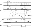
- FIG. 6 illustrates the principle of the present invention with the aid of incoming and outgoing symbols in the time domain
- FIG. 7 schematically shows an embodiment of the circuit according to the invention implementing the principle of FIG. 6 ;
- FIG. 8 illustrates incoming symbols with cyclic prefixes on a telephone line.
- the present invention replaces, in the echo signal, the contribution of the beginning portion of each symbol by the contribution of the beginning portion of the preceding symbol, which is equivalent to using cyclic suffixes without the cyclic suffixes being present in the signal.
- FIG. 6 shows successive incoming and outgoing symbols in the time domain, such as they appear at the input IN of FFT circuit 18 and at the output OUT of IFFT circuit 14 ( FIG. 1 ).
- the incoming symbols are delayed by a time interval ⁇ and they are illustrated with the local echo h(.) generated by the outgoing symbols.
- a current incoming symbol S′n overlaps a large end portion of the echo h(Sn) of a current outgoing symbol Sn and a small beginning portion h(Xn+1) of the echo of the next outgoing symbol Sn+1.
- One purpose of the invention is to replace the echo portion h(Xn+1) by a portion of same length h(Xn) of the beginning of the echo of symbol Sn.
- the echo portion h(Xn+1) is subtracted from the end portion of the currently received symbol S′n while the echo portion h(Xn) is added thereto.
- a new input signal IN′ is generated in which the incoming symbol S′n coincides with echo portions belonging to the same outgoing symbol, whereby the orthogonality between sub-carriers of received symbol S′n and sub-carriers of echoes of outgoing symbols is preserved.
- the transfer function h of the echo generation should be estimated, like in a conventional echo-canceller.
- the estimated transfer function is designated h*. As symbolized in FIG. 6 , this estimated transfer function h* is used for calculating, from the outgoing signal, the echo portions to add to, and subtract from, the incoming signal.
- the echoes are calculated according to the invention only for small portions of each symbol, not exceeding 5%.
- the size of the FIR filter to use is chosen to store only 5% of the samples of each symbol.
- the number of weighting coefficients to calculate does not exceed the size of the filter. For example, if the symbols to process have 4096 samples, the filter will have a size of 200, whereby the number of weighting coefficients to calculate is also 200.
- the length of the above echo portions should at least be equal to the delay ⁇ between the incoming and outgoing symbols. Since this delay ⁇ depends on various parameters, such as the subscriber line length, the length of the filter is chosen equal to the maximum delay, which is in fact the length conventionally chosen for the cyclic suffixes. However, if the delay ⁇ is shorter than the maximum value, it is possible to correspondingly reduce the number of weighting coefficients to calculate.
- FIG. 7 schematically shows an embodiment of a circuit implementing the principle described in relation with FIG. 6 .
- the outgoing time domain symbols S i.e. the output OUT of IFFT circuit 14 of FIG. 1 , are provided to a digital delay line 80 which introduces a delay of one symbol.
- the outgoing symbols S are also subtracted from the output of the delay line 80 by a subtractor 82 .
- Subtractor 82 thus provides the difference between an outgoing symbol Sn and the next outgoing symbol Sn+1. This difference is provided to an FIR filter 84 which is adjusted to have the estimated transfer function h* of the local echo generation.
- filter 84 is designed to operate only on a number of samples corresponding to delay ⁇ or the maximum value thereof. When filter 84 does not receive samples for which an echo should be estimated, it is held at a reset state so that it provides value zero.
- An exemplary reset signal RST is illustrated in FIG. 6 . It is inactive from the beginning of each outgoing symbol for a duration corresponding to the maximum value of delay ⁇ .
- filter 84 estimates the echo of the difference of two symbol portions (the subtraction is achieved by element 82 before the filter) which, since the filter is linear, is equivalent to the subtraction of the echoes of the two portions.
- the output of filter 84 is provided to an adder 86 which also receives the incoming symbols S′ affected by the non-orthogonal echo. Adder 86 provides the input signal IN′ of FFT circuit 18 , which signal has the desired orthogonal echo.
- the necessary weighting coefficients for filter 84 are provided by a calculating element 88 which implements a conventional echo-canceller algorithm using the input and output signals IN and OUT. Since this calculation algorithm does not depend on the output of the filter, the calculation may continue even during the periods when filter 84 is inactive. The weighting coefficients being evaluated by successive iterations, this permanent operation of the algorithm will allow a faster convergence of the weighting coefficients, especially at start-up of the system.
- Delay line 80 may be chosen of a size adapted to storing only the necessary portion of each symbol. In this case, delay line 80 is enabled only during the periods when the reset signal RST of the filter is inactive.
- cyclic prefixes CP are added to the symbols.
- This figure shows the incoming signal IN affected by the echo of the outgoing signal.
- a current incoming symbol S′n overlaps the echo of the current outgoing symbol Sn and of the prefix of the next outgoing symbol Sn+1. In this case, it is the echo of the prefix of the next outgoing symbol that is replaced by the echo of the beginning portion of the current outgoing symbol.
- the echo portion coming after the echo of an outgoing symbol is replaced by the echo of the beginning portion of the outgoing symbol.
- the delay line 80 is in fact a FIFO memory which is write enabled at least for time ⁇ from the beginning of each outgoing symbol and read enabled when filter 84 is operative, i.e. for at least time ⁇ from the end of each outgoing symbol.
- Corresponding write, read, and reset signals W, R, RST are shown in FIG. 8 .
Abstract
Description
Claims (23)
Applications Claiming Priority (1)
| Application Number | Priority Date | Filing Date | Title |
|---|---|---|---|
| EP99410014A EP1035700B1 (en) | 1999-03-05 | 1999-03-05 | DSL transmission system with means for ensuring local echo orthogonality |
Publications (1)
| Publication Number | Publication Date |
|---|---|
| US7103015B1 true US7103015B1 (en) | 2006-09-05 |
Family
ID=8242243
Family Applications (1)
| Application Number | Title | Priority Date | Filing Date |
|---|---|---|---|
| US09/517,417 Expired - Lifetime US7103015B1 (en) | 1999-03-05 | 2000-03-02 | DSL transmission system with means for ensuring local echo orthogonality |
Country Status (4)
| Country | Link |
|---|---|
| US (1) | US7103015B1 (en) |
| EP (1) | EP1035700B1 (en) |
| JP (1) | JP2000299650A (en) |
| DE (1) | DE69907864T2 (en) |
Families Citing this family (3)
| Publication number | Priority date | Publication date | Assignee | Title |
|---|---|---|---|---|
| KR100377429B1 (en) * | 2000-12-29 | 2003-03-26 | 엘지전자 주식회사 | ECHO Canceller of the ADSL system and controlling method therefor |
| AU2003276812A1 (en) | 2002-06-14 | 2003-12-31 | Globespan Virata Incorporated | System and method for applying transmit windowing in adsl+ networks |
| US20060203896A1 (en) * | 2005-03-11 | 2006-09-14 | Axel Clausen | Semi-digital duplexing |
Citations (13)
| Publication number | Priority date | Publication date | Assignee | Title |
|---|---|---|---|---|
| US5084865A (en) * | 1989-02-23 | 1992-01-28 | Nec Corporation | Echo canceller having fir and iir filters for cancelling long tail echoes |
| US5317596A (en) | 1992-12-01 | 1994-05-31 | The Board Of Trustees Of The Leland Stanford, Junior University | Method and apparatus for echo cancellation with discrete multitone modulation |
| US5521908A (en) * | 1995-04-20 | 1996-05-28 | Tellabs Operations Inc. | Method and apparatus for providing reduced complexity echo cancellation in a multicarrier communication system |
| US5577116A (en) * | 1994-09-16 | 1996-11-19 | North Carolina State University | Apparatus and method for echo characterization of a communication channel |
| WO1997006619A1 (en) | 1995-08-04 | 1997-02-20 | Telia Ab | Procedure to suppress near-end crosstalk at bidirectional communication in wire network |
| US5623513A (en) * | 1993-12-13 | 1997-04-22 | Amati Communications Corporation | Mitigating clipping and quantization effects in digital transmission systems |
| US5668802A (en) * | 1993-11-11 | 1997-09-16 | Gpt Limited | High-speed digital subscriber lines |
| US5751716A (en) * | 1996-06-19 | 1998-05-12 | Aware, Inc. | Multi-carrier transmission system adapted for packet data transfer |
| US6072782A (en) * | 1996-12-23 | 2000-06-06 | Texas Instruments Incorporated | Efficient echo cancellation for DMT MDSL |
| US6377683B1 (en) * | 1998-05-29 | 2002-04-23 | 3Com Corporation | Low complexity frequency domain echo canceller for DMT transceivers |
| US6535550B1 (en) * | 1999-03-02 | 2003-03-18 | Legerity, Inc. | Transceiver with variable width cyclic prefix |
| US6546055B1 (en) * | 1998-01-12 | 2003-04-08 | The Board Of Trustees Of The Leland Stanford Junior University | Carrier offset determination for RF signals having a cyclic prefix |
| US6845125B2 (en) * | 2000-03-07 | 2005-01-18 | Fujitsu Limited | xDSL transceiver |
-
1999
- 1999-03-05 EP EP99410014A patent/EP1035700B1/en not_active Expired - Lifetime
- 1999-03-05 DE DE69907864T patent/DE69907864T2/en not_active Expired - Lifetime
-
2000
- 2000-03-02 US US09/517,417 patent/US7103015B1/en not_active Expired - Lifetime
- 2000-03-03 JP JP2000059264A patent/JP2000299650A/en not_active Withdrawn
Patent Citations (13)
| Publication number | Priority date | Publication date | Assignee | Title |
|---|---|---|---|---|
| US5084865A (en) * | 1989-02-23 | 1992-01-28 | Nec Corporation | Echo canceller having fir and iir filters for cancelling long tail echoes |
| US5317596A (en) | 1992-12-01 | 1994-05-31 | The Board Of Trustees Of The Leland Stanford, Junior University | Method and apparatus for echo cancellation with discrete multitone modulation |
| US5668802A (en) * | 1993-11-11 | 1997-09-16 | Gpt Limited | High-speed digital subscriber lines |
| US5623513A (en) * | 1993-12-13 | 1997-04-22 | Amati Communications Corporation | Mitigating clipping and quantization effects in digital transmission systems |
| US5577116A (en) * | 1994-09-16 | 1996-11-19 | North Carolina State University | Apparatus and method for echo characterization of a communication channel |
| US5521908A (en) * | 1995-04-20 | 1996-05-28 | Tellabs Operations Inc. | Method and apparatus for providing reduced complexity echo cancellation in a multicarrier communication system |
| WO1997006619A1 (en) | 1995-08-04 | 1997-02-20 | Telia Ab | Procedure to suppress near-end crosstalk at bidirectional communication in wire network |
| US5751716A (en) * | 1996-06-19 | 1998-05-12 | Aware, Inc. | Multi-carrier transmission system adapted for packet data transfer |
| US6072782A (en) * | 1996-12-23 | 2000-06-06 | Texas Instruments Incorporated | Efficient echo cancellation for DMT MDSL |
| US6546055B1 (en) * | 1998-01-12 | 2003-04-08 | The Board Of Trustees Of The Leland Stanford Junior University | Carrier offset determination for RF signals having a cyclic prefix |
| US6377683B1 (en) * | 1998-05-29 | 2002-04-23 | 3Com Corporation | Low complexity frequency domain echo canceller for DMT transceivers |
| US6535550B1 (en) * | 1999-03-02 | 2003-03-18 | Legerity, Inc. | Transceiver with variable width cyclic prefix |
| US6845125B2 (en) * | 2000-03-07 | 2005-01-18 | Fujitsu Limited | xDSL transceiver |
Non-Patent Citations (1)
| Title |
|---|
| European Search Report from European Application 99410014.7, filed Mar. 5, 1999. |
Also Published As
| Publication number | Publication date |
|---|---|
| JP2000299650A (en) | 2000-10-24 |
| EP1035700A1 (en) | 2000-09-13 |
| DE69907864D1 (en) | 2003-06-18 |
| EP1035700B1 (en) | 2003-05-14 |
| DE69907864T2 (en) | 2004-05-06 |
Similar Documents
| Publication | Publication Date | Title |
|---|---|---|
| US7023908B2 (en) | DSL transmission system with far-end crosstalk compensation | |
| US5117418A (en) | Frequency domain adaptive echo canceller for full-duplex data transmission | |
| JP3604937B2 (en) | Reduction of interference in a communication system based on discrete multitone (DMT) | |
| JP4588168B2 (en) | Fast training of equalizers in DMT systems | |
| US6618480B1 (en) | DAC architecture for analog echo cancellation | |
| US6987800B2 (en) | DSL transmission system with far-end crosstalk cancellation | |
| EP0908020A2 (en) | Frequency domain signal reconstruction in sampled digital communications systems | |
| WO2001093448A2 (en) | Frequency domain echo canceller | |
| US6400782B2 (en) | Method of frequency domain filtering employing a real to analytic transform | |
| WO1995017046A1 (en) | An improved discrete multitone echo canceler | |
| EP0098000A2 (en) | Digital duplex communication system | |
| US6788752B1 (en) | Multi-carrier transmission system | |
| US7103015B1 (en) | DSL transmission system with means for ensuring local echo orthogonality | |
| US6781965B1 (en) | Method and apparatus for echo cancellation updates in a multicarrier transceiver system | |
| EP0991202B1 (en) | Dsl transmission system with echo-cancellation | |
| EP3190757A1 (en) | Multi-tones narrow band rf noise elimination through adaptive algorithm | |
| US6687288B1 (en) | NEXT cancellation for modem pools | |
| JP2005530393A (en) | Digital echo canceller | |
| KR100475771B1 (en) | Device and method for echo compensation in a two-wire full duplex channel transmission method | |
| KR20020069265A (en) | System and Method For Application of An LMS Method To Updating An Echo Canceller In An ADSL Modem | |
| JP3502607B2 (en) | Digital receiver for signals generated by discrete multitone modulation | |
| US6647076B1 (en) | Method of compensating for interference in a signal generated by discrete multitone modulation, and circuit configuration for carrying out the method. | |
| KR100456759B1 (en) | Radio frequency noise canceller | |
| EP1296492A1 (en) | Multicarrier receiver with a sliding window Fourier transform and a Fourier transform | |
| KR100450606B1 (en) | Echo Compensation Device |
Legal Events
| Date | Code | Title | Description |
|---|---|---|---|
| AS | Assignment |
Owner name: TELIA AB, SWEDEN Free format text: ASSIGNMENT OF ASSIGNORS INTEREST;ASSIGNORS:ISSON, OLIVIER;NORDSTROM, TOMAS;REEL/FRAME:010810/0427;SIGNING DATES FROM 20000404 TO 20000417 Owner name: STMICROELECTRONICS S.A., FRANCE Free format text: ASSIGNMENT OF ASSIGNORS INTEREST;ASSIGNORS:ISSON, OLIVIER;NORDSTROM, TOMAS;REEL/FRAME:010810/0427;SIGNING DATES FROM 20000404 TO 20000417 |
|
| AS | Assignment |
Owner name: STMICROELECTRONICS N.V., NETHERLANDS Free format text: ASSIGNMENT OF ASSIGNORS INTEREST;ASSIGNOR:TELIA AB;REEL/FRAME:011346/0001 Effective date: 20000502 |
|
| AS | Assignment |
Owner name: STMICROELECTRONICS N.V., NETHERLANDS Free format text: ASSIGNMENT OF ASSIGNORS INTEREST;ASSIGNORS:DORREN, BASTIAAN HENDRIK PETER;BLANSAER, EDDY;BOSSCHE, LUC JOZEF LOUISE VAN DEN;AND OTHERS;REEL/FRAME:014509/0619;SIGNING DATES FROM 20030729 TO 20030808 |
|
| STCF | Information on status: patent grant |
Free format text: PATENTED CASE |
|
| CC | Certificate of correction | ||
| FEPP | Fee payment procedure |
Free format text: PAYOR NUMBER ASSIGNED (ORIGINAL EVENT CODE: ASPN); ENTITY STATUS OF PATENT OWNER: LARGE ENTITY |
|
| FPAY | Fee payment |
Year of fee payment: 4 |
|
| FPAY | Fee payment |
Year of fee payment: 8 |
|
| MAFP | Maintenance fee payment |
Free format text: PAYMENT OF MAINTENANCE FEE, 12TH YEAR, LARGE ENTITY (ORIGINAL EVENT CODE: M1553) Year of fee payment: 12 |