US7106931B2 - Optical fiber drop cables - Google Patents
Optical fiber drop cables Download PDFInfo
- Publication number
- US7106931B2 US7106931B2 US10/495,980 US49598004A US7106931B2 US 7106931 B2 US7106931 B2 US 7106931B2 US 49598004 A US49598004 A US 49598004A US 7106931 B2 US7106931 B2 US 7106931B2
- Authority
- US
- United States
- Prior art keywords
- cable
- sheathing
- optical fibre
- strengthening
- passage
- Prior art date
- Legal status (The legal status is an assumption and is not a legal conclusion. Google has not performed a legal analysis and makes no representation as to the accuracy of the status listed.)
- Expired - Lifetime
Links
Images


Classifications
-
- H—ELECTRICITY
- H02—GENERATION; CONVERSION OR DISTRIBUTION OF ELECTRIC POWER
- H02G—INSTALLATION OF ELECTRIC CABLES OR LINES, OR OF COMBINED OPTICAL AND ELECTRIC CABLES OR LINES
- H02G3/00—Installations of electric cables or lines or protective tubing therefor in or on buildings, equivalent structures or vehicles
- H02G3/02—Details
- H02G3/04—Protective tubing or conduits, e.g. cable ladders or cable troughs
- H02G3/0462—Tubings, i.e. having a closed section
- H02G3/0487—Tubings, i.e. having a closed section with a non-circular cross-section
-
- G—PHYSICS
- G02—OPTICS
- G02B—OPTICAL ELEMENTS, SYSTEMS OR APPARATUS
- G02B6/00—Light guides; Structural details of arrangements comprising light guides and other optical elements, e.g. couplings
- G02B6/46—Processes or apparatus adapted for installing or repairing optical fibres or optical cables
- G02B6/48—Overhead installation
- G02B6/483—Installation of aerial type
-
- G—PHYSICS
- G02—OPTICS
- G02B—OPTICAL ELEMENTS, SYSTEMS OR APPARATUS
- G02B6/00—Light guides; Structural details of arrangements comprising light guides and other optical elements, e.g. couplings
- G02B6/44—Mechanical structures for providing tensile strength and external protection for fibres, e.g. optical transmission cables
- G02B6/4401—Optical cables
- G02B6/4415—Cables for special applications
- G02B6/4416—Heterogeneous cables
Definitions
- the invention relates to optical fibre drop cables for use in telecommunications systems and particularly, but not exclusively, to such cables for use in connecting between a customer's premises and a connection point common to a number of such customers.
- a final drop wire has typically comprised a number of insulated conducting wires contained in a sheath. More recently the development of optical fibers has made it desirable to replace the conducting wires in drop wires with optical fibers, since the latter can transmit significantly more data. However, it is also desirable that the drop wire should carry an electrical supply in order that a telephone connected to the drop wire can be used in emergency situations when the mains electrical supply to the premises in which the telephone is located has been interrupted. For this reason, it is desirable for a drop wire to include one or more optical fibers and a pair of insulated copper conductor wires.
- the applicant's application GB-A-2270992 discloses a cable containing separable electrical conductors and optical fibers.
- the cable comprises electrical power conductors for conveying mains voltage electrical supplies, a plurality of optical fibers and sheathing for the conductors and fibers.
- the sheathing is in the form of a figure of eight and defines two separate chambers; one for the electrical conductors and the other for the optical fibers.
- this cable is intended for underground routing and not for suspension installation. Furthermore, it is not suitable for conducting a relatively low voltage electrical supply for powering a telephone or otherwise as a final drop wire.
- An aspect of the invention relates to an optical fibre drop cable for suspension installation, said cable comprising sheathing having a first portion containing a strengthening arrangement for supporting the cable in a said suspension installation and a second portion separable from said first portion and containing a plurality of electrical conductors, said first portion defining at least one passage for optical fibers.
- FIG. 1 is a schematic cross-section of an optical fibre drop cable comprising an optical fibre and electrical conductors
- FIG. 2 is a schematic cross-section of an optical fibre drop cable containing a plurality of optical fibers and electrical conductors;
- FIG. 3 is a schematic cross-section of an optical fibre drop cable comprising an optical fibre and electrical conductors
- FIG. 4 is a schematic representation of a drop cable installation including a cable as shown in FIG. 1 , 2 or 3 ;
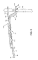
- FIG. 5 is an enlargement of the portion of FIG. 4 ;
- FIG. 6 is a schematic representation of a connecting box of the installation of FIG. 4 ;
- FIG. 7 shows a push-fit connector arrangement included in the connecting box.
- FIG. 1 shows an optical fibre drop cable 10 containing a buffered optical fibre 11 and two insulated electrical conductors 12 .
- the buffered optical fibre 11 comprises an optical fibre 13 and a plastics coating 14 that protects the surface of the fibre 13 from scratching and abrasion.
- the plastics coating may for example be a nylon coating and the fibre with coating will typically have a diameter of approximately 1 mm.
- the insulated conductors 12 comprise copper wires 16 encapsulated in a colour-coded electrical insulating coating 18 , which may be of any suitable material as will be well known to those skilled in the art.
- the copper wires will have a diameter of approximately 0.4 mm and the outside diameter of the insulating coating will typically be approximately 1.2 mm
- One insulated conductor 12 is to serve as the live wire and the other as a neutral/earth wire in a circuit that will typically carry 9 to 12 volts for powering a telephone connected with the cable. It is to be understood that copper wires are given, only as an example and that any suitable conducting material, such as aluminium could be used instead.
- the optical fibre 11 and electrical conductors 12 are housed in sheathing 19 , which comprises a first portion 20 that contains the optical fibre 13 and a second portion 22 that is separable front the first portion and contains the electrical conductors 12 .
- the optical fibre 11 is housed in a passage 23 defined by the first portion 20 with the wall defining the passage circumferentially engaging the optical fibre along the length of the fibre.
- the sheathing portions 20 , 22 are substantially circular in cross-section and in side-by-side parallel relationship so as to define a shape approximating to a FIG. 8 .
- a thickening, or web, 24 At the point of connection between the sheathing portions, there is a thickening, or web, 24 .
- the web houses a tear, or rip, cord 26 which is offset with respect to a plane passing through the longitudinal axes of the first and second sheathing portions and runs along the cable substantially parallel to those axes.
- the rip cord 26 may be made of any material sufficiently strong to rip through the web 24 on application of a tear force so as to permit separation of the first and second sheathing portions.
- One suitable material for the rip cord is a high strength Terylene ( TN ) string.
- the sheathing 19 may be made of any suitable sheathing material such as polyethylene, MDPE, HDPE or nylon.
- the first portion 20 of the sheathing would have a diameter of approximately 8 mm and the combined height of the two sheathing portions would be approximately 12 mm.
- a strengthening arrangement is provided in the first portion 19 of the sheathing in the form of strengthening members 28 disposed adjacent the optical fibre 11 .
- the strengthening members 28 are disposed in parallel spaced apart relationship, one on each side of the optical fibre 11 and encapsulated in the first portion 20 of the sheathing.
- the strengthening members are preferably disposed in a plane P 1 extending perpendicular to a plane P 2 passing through the respective longitudinal axes of the sheathing portions 20 , 22 and through the longitudinal axis of the first portion 20 of the sheathing.
- the strengthening members 28 have a substantially circular cross-section and extend generally parallel to the longitudinal axis the first portion 20 of the sheathing.
- the strengthening members are made of a dielectric material such as glass reinforced plastic (GRP), although glass yarns may be used with similar advantage.
- a dielectric material such as glass reinforced plastic (GRP)
- GRP glass reinforced plastic
- Other non-preferred materials include aramid fibers.
- dielectric materials are preferred, metallic strengthening elements may be used.
- GRP strengthening materials are a preferred material since the material has a similar coefficient of thermal expansion to optical fibers and thus changes in length of the strengthening members due to thermal effects, should not result in an increase in the forces transmitted to the optical fibre. Glass yarns offer a similar advantage.
- strengthening members made of an electrically non-conducting material such as GRP, glass yarn or aramid fibers. If the strengthening members are made of an electrically conducting material such as a stranded steel, it is necessary to increase the diameter of the sheathing for electrical insulation purposes. When electrically non-conducting strengthening members are used, there is no requirement to maintain an increased thickness of sheathing in the first portion 20 of the sheathing in order to meet any voltage withstand requirement. Thus, the diameter of the first portion of the sheathing can be reduced, which reduces the effect of ice and wind loads on the cable. It is believed that by using electrically non-conducting strengthening members, the diameter of the first portion 19 of the sheathing can be reduced by up to 2 mm as compared with the case when the sheathing is required to provide electrical insulation.
- the optical fibre drop cable 40 shown in FIG. 2 shows modifications which may be made to the optical drop fibre 10 singly or in combination.
- the first modification comprises the addition of two further strengthening members 28 .
- the four strengthening members 28 of the optical fibre cable 40 are disposed on a common pitch circle and are spaced at 90° intervals on that circle, such that a plane passing through the longitudinal axes of the first and second portions 20 , 22 of the sheathing passes through the longitudinal axis of two of the strengthening members and a second plane perpendicular to that plane passes through the longitudinal axes of the other two strengthening members.
- the second modification comprises the provision of two optical fibers 11 . As shown in the drawing, the optical fibers 11 are loosely housed in a circular passage 44 .
- the first portion 20 of the sheathing may be formed so as to define a single passage or separate passages encasing the optical fibers in the same way as in the optical fibre cable 10 in FIG. 1 .
- FIG. 3 shows an optical fibre drop cable 60 that differs from the optical fibre drop cable 10 in that the optical fibre 11 is loosely housed in a hollow plastic tube 62 contained in a passage 63 defined by the first sheathing portion 20 .
- This tube may contain more than one optical fibre although only one is shown in the drawing.
- a possible modification (not shown) to the optical fibre cable drop 60 shown in FIG. 3 comprises omitting the optical fibre(s) 11 from the tube 62 .
- one or more fibers 11 are blown into the tube after installation of the optical fibre drop cable.
- Optical fibers to be installed by blown fibre methods may, for example, take the form disclosed in EP-A-0345968, EP-A-0521710 or EP-A-0646818 and may be introduced into the tube 62 by known blowing processes such as the process described in EP-A-0108590.
- the tube 62 may be made of polyethylene with a carbon loaded radially inner surface to increase conductivity, as disclosed in U.S. Pat. No. 4,952,021. Blown fibre installation has the advantage that optical fibre(s) are not subjected to stresses that arise during suspension of the cable.
- optical fibre drop cables 10 , 40 , 60 comprises replacing the strengthening members 28 with a strengthening arrangement in the form of a reinforcing sleeve contained in the first portion 20 of the sheathing.
- the sleeve would preferably be made of an electrically non-conducting material such as aramid fibers.
- the sleeve could be made of strands of a metallic element such as steel.
- the fibers or strands of such a sleeve would preferably be helically wound around the optical fibre(s) 11 and/or tube(s) 62 and electrical conductors 12 from two directions—a so-called SZ winding.
- FIG. 4 shows a drop installation 100 comprising any of the optical fibre drop cables 10 , 40 and 60 .
- the installation comprising the optical fibre drop cable 10 .
- the drop installation 100 includes a housing 101 containing a distribution arrangement for distributing connections to telecommunications lines that are to run to customer premises.
- the housing is fed from an exchange by means of a multifibre optical fibre cable 102 such as a known 48 fibre underground cable.
- a multifibre optical fibre cable 103 comprising sufficient fibers for connecting with ten telecommunications lines 104 (ten fibers for single fibre circuits or twenty fibers for twin fibre circuits), leads from the housing 101 to a connecting box, or manifold 105 of an adjacent pole 106 .
- the reference numeral 103 indicates electrical conductors for conducting a voltage of 9 to 12 volts to the manifold.
- a telecommunications line 104 runs from the manifold 105 to customer premises such as a building 107 .
- customer premises such as a building 107 .
- two telecommunications lines 104 are shown; one extending to the right of the manifold and leading to the building 107 and the other extending to the left of the manifold.
- the optical fibre cable 103 contains sufficient optical fibers to connect with ten telecommunications lines 104 and thus there may be ten separate telecommunications lines extending from the manifold 105 .
- the telecommunications lines 104 each comprise a plurality of lengths of the optical fibre drop cable 10 connected end-to-end at respective connecting boxes 108 mounted on poles 106 and the building 107 .
- the lengths of cable 10 are connected to the poles 106 by securing devices 110 .
- securing devices 110 In the drawing, only two poles are shown, but in practice there will be as many poles as are required to support the cable en route between the manifold 105 and the customer premises. Typically the spacing between the poles is approximately 200 feet (61 meters), although it may be up to 100 meters.
- each securing device 110 comprises an elongate member 112 which is bent double to define two end portions 114 , 116 that are helically wrapped around the first portion 20 of the sheathing in the same sense, and a bend, or loop, 118 that connects the end portions.
- the securing device 110 additionally comprises a tensile connecting member 120 having hooked end portions, one of which engages the loop 118 and the other of which engages a pole ring 122 fixed to the pole 106 .
- the tensile connecting member 120 may include means (not shown) for adjusting the tension in the cable 10 between the securing devices on adjacent poles 106 .
- the tensile connecting member may comprise two portions each having threading at their ends remote from the hooked end portions and interconnected by a nut such that rotation of the nut causes lengthening or shortening of the tensile connecting member.
- the second portion 22 containing the electrical conductors 12 is separated from the first portion 19 .
- This separation is easily obtained by accessing the free end of the rip cord 26 at the adjacent end of the optical fibre cable 10 and using this to rip through the web 24 over a suitable distance.
- a break is shown in the separated portion of the first portion 19 of the sheathing simply to allow a better view of the loop 118 and the tensile connecting member 120 .
- a connecting box 108 has a hollow interior 130 , that can be accessed by removing a cover plate (not shown).
- An opening 132 for a cable 10 is provided at each side of the box to serve as an entry point for an end of a cable 10 .
- pairs of openings may be provided for individually receiving the separated sheathing portions.
- the connecting boxes 108 are secured to the poles 106 by any suitable means, such as screws 133 .
- Each box contains a push-fit connector arrangement, or device, 134 by means of which the ends of the cables 10 are secured within the box.
- the push-fit connector arrangement 134 may utilise any suitable known push-fit technology and has two push-fit connection points 135 at spaced apart positions, one for each cable end.
- the push-fit connection points 135 may each include two push-fit connectors such as the push-fit connector 136 as shown in FIG. 7 .
- Each push-fit connector 136 comprises a body 138 that defines a stepped through-passage 140 .
- a gripping means 142 that comprises a ring having a plurality of circumferentially spaced apart radially and axially inwardly extending projections, or barbs is housed in a larger diameter portion 144 of the through-passage 140 at a position remote from the ends of the through-passage.
- the gripping means 142 is preferably made of metal, but may be made of a plastics material, and the barbs are able to deflect radially outwardly on insertion of an end of a sheathing portion 20 , 22 into the through-passage 140 (from the right as viewed in the drawing), but dig into the sheathing if the cable is pulled in the direction opposite to the direction of insertion so as to resist subsequent withdrawal of the sheathing portion from the connection point 135 .
- a collet 146 may be provided to permit withdrawal of the sheathing portion should it become desirable to break the connection.
- the collet 146 has a cylindrical leading-end portion 148 which projects into the through-passage 140 and is engageable with the barbs on axial inward movement relative to the gripping means 142 to deflect the barbs radially outwardly to release the grip on the sheathing portion and permit its withdrawal.
- the separated first and second sheathing portions 20 , 22 of the respective ends of the cables are fed through the openings 132 into the hollow interior of the connecting box 108 .
- the sheathing and strengthening members 28 are cut back to expose the optical fibre 11 and insulated conductors 12 and then the ends of the sheathing portions are push-fitted into the respective push-fit connectors 136 until the cut end of the sheathing abuts a shoulder 150 defined by the through-passage 140 .
- the ends of the first and second portions of the sheathing are secured in the push-fit connectors 136 by the barbs of the gripping means 142 and the exposed optical fibre 11 and insulated conductors 12 protrude from the inner ends 152 of the through-passages to a connection region 154 of the connecting box.
- the electrical conductors and optical fibers of the cable ends are connected by any suitable conventional means.
- the conductors 12 may be connected by stripping back the insulating coating 18 to expose the copper wires 16 and twisting the ends of the wires together.
- a terminal block in which the ends of the conducting wires are secured by means of screws may be used.
- the manifold 105 may be of similar construction to a connecting box 108 .
- the manifold 105 would contain an additional opening through which the optical fibre cable 103 is fed and ten openings 132 to permit ten telecommunications lines 104 to feed from the manifold.
- the ends of the telecommunications lines 104 can be secured in the manifold 105 by means of push-fit connectors, such as the push-fit connectors 136 in the same way as in the connecting boxes 108 , or by any other suitable means.
- connections between the electrical conductors feeding into the manifold and the optical fibers of the optical fibre 103 may be made with the electrical conductors 12 and optical fibers 11 by any suitable conventional means. As shown in FIG.
- the lengths of optical fibre drop cable 10 suspended between the poles 106 are connected to the poles by the securing devices 110 , which are secured to the cable at spaced apart positions remote from its ends.
- the tension in the cable suspended between the poles can be adjusted after suspension of the cable by means of the adjusting means of the tensile connecting members 120 if such means are provided.
- the end portions 10 E ( FIG. 5 ) of the first portion of the sheathing and its contents between the securing devices 110 and the connecting boxes 108 are untensioned.
- the helical winding of the ends 114 , 116 of the elongate member 112 can be adapted such that it will grip the sheathing with a predetermined force so that the sheathing will slip when the tension in the cable 10 reaches or exceeds a predetermined level.
- the previously untensioned portions 10 E will be tensioned and the connection points 136 are arranged such that the cable will be released, breaking the connection with the adjacent lengths of cable when the tension in the portion 10 E reaches a second predetermined level which is no greater than the tension load that causes the slippage of the cable and is preferably substantially less.
- the tension load at which the elongate member 112 permits slippage of the cable is selected such that the cable will slip at a loading less than that required to break the cable. It is expected that the strength of the cable would be such that it would break under a load in the region of 2 KN, that the elongate member 112 would be arranged to permit slippage of the cable under a load in the region of 1.2 to 1.5 KN and the push-fit connectors would be arranged to permit the cable connections to break at a load in the region of 170 N, although it is to be understood that these loads are given as examples and should not be taken as limiting.
- the ends 10 E are described as being secured to the connecting box 106 by means of a push-fit arrangement. It will be appreciated that this arrangement whilst advantageous in terms of simplicity and ease of fitting, should not be taken as limiting.
- the ends 10 E may be secured by any suitable means, such as a spring-loaded cable clamp that will provide sufficient security to hold the ends 10 E in place and avoid any tensile load being transmitted to the joints between the optical fibers 11 and conductors 12 during normal operating conditions and at the same time reliably permit breakage of the connection at a tensile loading no greater than that required to cause slippage of the cable through the securing devices 110 .
- the telecommunications line 104 is to be constructed using an optical fibre drop cable 60 as shown in FIG. 3 , with the optical fibre(s) being installed by blown fibre technique, it is necessary to provide a substantially gas-tight passage along which the optical fibers are to be blown.
- the first portion 20 of the sheathing is cut back such that when its end is push-fitted into a push-fit connector 136 , the cut end of the plastics tube 62 protrudes from the end 152 of the through-passage 140 into the connection region 154 .
- the ends of the tubes 62 protruding into the connection region can then be interconnected to provide a gas-tight passage for the optical fibre(s) by means of a suitable length of tubing inserted therebetween.
- means defining a passage could be provided between the push-fit connection points 135 and arranged such that the ends of the tubes 62 can be inserted therein to provide a continuous air-tight passage for the optical fibre(s).
- optical fibre drop cables are described as being used in the drop installation 100 , which provides for a controlled breakage of the telecommunications line, this is not essential and the cables could be used in any suitable conventional drop installation.
- the optical fibre drop cables 10 , 40 , 60 are installed in an arrangement such as the arrangement 100 that provides controlled breakage of the telecommunications line under a load less than that required to break the cable, it will be appreciated that such an arrangement is advantageous. This is because the loading which will cause the optical fibre drop cable to slip and the connection between adjacent ends to break can be chosen to be less than that required to break the cable, which is a useful safety feature in the event of a high vehicle driving into the telecommunications line 104 or a tree or other structure falling on it.
- the connections between a length of the optical fibre drop cable and adjacent lengths in the line are broken in the event of such events, damage to the telecommunications line should be localised thereby reducing the time required for and cost of repair.
- the telecommunications line can be designed to break on application of a predetermined loading, the cable can be made significantly stronger than might otherwise be the case, thereby providing greater protection for the optical fibre(s) contained in the cable.
- the cable can be made stiffer and thus able to better withstand the effects of variable loading due to wind force and the settling of moisture or ice formation.
- the strengthening arrangement can directly control the thermal and tensile performance of the cable and provide better protection for the optical fibre(s) by virtue of its close proximity to it/them. It also provides the advantage that if the sheathing portions are to be separated for installation in an arrangement such as that shown in FIGS. 4 and 5 , no special measures need be taken to protect the optical fibre(s) in the region in which the sheathing portions are separated.
- the optical fibre drop cables of the embodiments are low fibre count cables intended to be used in aerial installations as a final drop wire. It is envisaged that such a low fibre count cable may comprise only one or two optical fibers. Furthermore, the electrical conductors are intended to carry only a low voltage, preferably in the region of 9 to 12 volts, and only two conductors are needed for this purpose.
Abstract
Description
Claims (25)
Applications Claiming Priority (3)
| Application Number | Priority Date | Filing Date | Title |
|---|---|---|---|
| EP013097274 | 2001-11-19 | ||
| EP01309727 | 2001-11-19 | ||
| PCT/GB2002/005153 WO2003044584A1 (en) | 2001-11-19 | 2002-11-15 | Optical fibre drop cables |
Publications (2)
| Publication Number | Publication Date |
|---|---|
| US20050002622A1 US20050002622A1 (en) | 2005-01-06 |
| US7106931B2 true US7106931B2 (en) | 2006-09-12 |
Family
ID=8182472
Family Applications (1)
| Application Number | Title | Priority Date | Filing Date |
|---|---|---|---|
| US10/495,980 Expired - Lifetime US7106931B2 (en) | 2001-11-19 | 2002-11-15 | Optical fiber drop cables |
Country Status (9)
| Country | Link |
|---|---|
| US (1) | US7106931B2 (en) |
| EP (1) | EP1446689B1 (en) |
| JP (1) | JP2005510027A (en) |
| CN (1) | CN1589417B (en) |
| AU (1) | AU2002339166B2 (en) |
| BR (2) | BR0206428A (en) |
| CA (1) | CA2467513C (en) |
| ES (1) | ES2401082T3 (en) |
| WO (1) | WO2003044584A1 (en) |
Cited By (53)
| Publication number | Priority date | Publication date | Assignee | Title |
|---|---|---|---|---|
| US20100054746A1 (en) * | 2007-07-24 | 2010-03-04 | Eric Raymond Logan | Multi-port accumulator for radio-over-fiber (RoF) wireless picocellular systems |
| US7787823B2 (en) | 2006-09-15 | 2010-08-31 | Corning Cable Systems Llc | Radio-over-fiber (RoF) optical fiber cable system with transponder diversity and RoF wireless picocellular system using same |
| US7848654B2 (en) | 2006-09-28 | 2010-12-07 | Corning Cable Systems Llc | Radio-over-fiber (RoF) wireless picocellular system with combined picocells |
| US8111998B2 (en) | 2007-02-06 | 2012-02-07 | Corning Cable Systems Llc | Transponder systems and methods for radio-over-fiber (RoF) wireless picocellular systems |
| US8175459B2 (en) | 2007-10-12 | 2012-05-08 | Corning Cable Systems Llc | Hybrid wireless/wired RoF transponder and hybrid RoF communication system using same |
| US20120145453A1 (en) * | 2010-12-14 | 2012-06-14 | General Cable Technologies Corporation | Power cable with microduct |
| US8275265B2 (en) | 2010-02-15 | 2012-09-25 | Corning Cable Systems Llc | Dynamic cell bonding (DCB) for radio-over-fiber (RoF)-based networks and communication systems and related methods |
| US8472767B2 (en) | 2006-05-19 | 2013-06-25 | Corning Cable Systems Llc | Fiber optic cable and fiber optic cable assembly for wireless access |
| US8548330B2 (en) | 2009-07-31 | 2013-10-01 | Corning Cable Systems Llc | Sectorization in distributed antenna systems, and related components and methods |
| US8644844B2 (en) | 2007-12-20 | 2014-02-04 | Corning Mobileaccess Ltd. | Extending outdoor location based services and applications into enclosed areas |
| US8873585B2 (en) | 2006-12-19 | 2014-10-28 | Corning Optical Communications Wireless Ltd | Distributed antenna system for MIMO technologies |
| US9037143B2 (en) | 2010-08-16 | 2015-05-19 | Corning Optical Communications LLC | Remote antenna clusters and related systems, components, and methods supporting digital data signal propagation between remote antenna units |
| US9042732B2 (en) | 2010-05-02 | 2015-05-26 | Corning Optical Communications LLC | Providing digital data services in optical fiber-based distributed radio frequency (RF) communication systems, and related components and methods |
| US9112611B2 (en) | 2009-02-03 | 2015-08-18 | Corning Optical Communications LLC | Optical fiber-based distributed antenna systems, components, and related methods for calibration thereof |
| US9178635B2 (en) | 2014-01-03 | 2015-11-03 | Corning Optical Communications Wireless Ltd | Separation of communication signal sub-bands in distributed antenna systems (DASs) to reduce interference |
| US9184843B2 (en) | 2011-04-29 | 2015-11-10 | Corning Optical Communications LLC | Determining propagation delay of communications in distributed antenna systems, and related components, systems, and methods |
| US9219879B2 (en) | 2009-11-13 | 2015-12-22 | Corning Optical Communications LLC | Radio-over-fiber (ROF) system for protocol-independent wired and/or wireless communication |
| US9240835B2 (en) | 2011-04-29 | 2016-01-19 | Corning Optical Communications LLC | Systems, methods, and devices for increasing radio frequency (RF) power in distributed antenna systems |
| US9247543B2 (en) | 2013-07-23 | 2016-01-26 | Corning Optical Communications Wireless Ltd | Monitoring non-supported wireless spectrum within coverage areas of distributed antenna systems (DASs) |
| US9258052B2 (en) | 2012-03-30 | 2016-02-09 | Corning Optical Communications LLC | Reducing location-dependent interference in distributed antenna systems operating in multiple-input, multiple-output (MIMO) configuration, and related components, systems, and methods |
| US9325429B2 (en) | 2011-02-21 | 2016-04-26 | Corning Optical Communications LLC | Providing digital data services as electrical signals and radio-frequency (RF) communications over optical fiber in distributed communications systems, and related components and methods |
| US9357551B2 (en) | 2014-05-30 | 2016-05-31 | Corning Optical Communications Wireless Ltd | Systems and methods for simultaneous sampling of serial digital data streams from multiple analog-to-digital converters (ADCS), including in distributed antenna systems |
| US9385810B2 (en) | 2013-09-30 | 2016-07-05 | Corning Optical Communications Wireless Ltd | Connection mapping in distributed communication systems |
| US9419321B2 (en) | 2011-08-12 | 2016-08-16 | Commscope Technologies Llc | Self-supporting stripline RF transmission cable |
| US9420542B2 (en) | 2014-09-25 | 2016-08-16 | Corning Optical Communications Wireless Ltd | System-wide uplink band gain control in a distributed antenna system (DAS), based on per band gain control of remote uplink paths in remote units |
| US9455784B2 (en) | 2012-10-31 | 2016-09-27 | Corning Optical Communications Wireless Ltd | Deployable wireless infrastructures and methods of deploying wireless infrastructures |
| US9525488B2 (en) | 2010-05-02 | 2016-12-20 | Corning Optical Communications LLC | Digital data services and/or power distribution in optical fiber-based distributed communications systems providing digital data and radio frequency (RF) communications services, and related components and methods |
| US9525472B2 (en) | 2014-07-30 | 2016-12-20 | Corning Incorporated | Reducing location-dependent destructive interference in distributed antenna systems (DASS) operating in multiple-input, multiple-output (MIMO) configuration, and related components, systems, and methods |
| US9531452B2 (en) | 2012-11-29 | 2016-12-27 | Corning Optical Communications LLC | Hybrid intra-cell / inter-cell remote unit antenna bonding in multiple-input, multiple-output (MIMO) distributed antenna systems (DASs) |
| US9602210B2 (en) | 2014-09-24 | 2017-03-21 | Corning Optical Communications Wireless Ltd | Flexible head-end chassis supporting automatic identification and interconnection of radio interface modules and optical interface modules in an optical fiber-based distributed antenna system (DAS) |
| US9621293B2 (en) | 2012-08-07 | 2017-04-11 | Corning Optical Communications Wireless Ltd | Distribution of time-division multiplexed (TDM) management services in a distributed antenna system, and related components, systems, and methods |
| US9647758B2 (en) | 2012-11-30 | 2017-05-09 | Corning Optical Communications Wireless Ltd | Cabling connectivity monitoring and verification |
| US9661781B2 (en) | 2013-07-31 | 2017-05-23 | Corning Optical Communications Wireless Ltd | Remote units for distributed communication systems and related installation methods and apparatuses |
| US9673904B2 (en) | 2009-02-03 | 2017-06-06 | Corning Optical Communications LLC | Optical fiber-based distributed antenna systems, components, and related methods for calibration thereof |
| US9681313B2 (en) | 2015-04-15 | 2017-06-13 | Corning Optical Communications Wireless Ltd | Optimizing remote antenna unit performance using an alternative data channel |
| US9715157B2 (en) | 2013-06-12 | 2017-07-25 | Corning Optical Communications Wireless Ltd | Voltage controlled optical directional coupler |
| US9729267B2 (en) | 2014-12-11 | 2017-08-08 | Corning Optical Communications Wireless Ltd | Multiplexing two separate optical links with the same wavelength using asymmetric combining and splitting |
| US9730228B2 (en) | 2014-08-29 | 2017-08-08 | Corning Optical Communications Wireless Ltd | Individualized gain control of remote uplink band paths in a remote unit in a distributed antenna system (DAS), based on combined uplink power level in the remote unit |
| US9775123B2 (en) | 2014-03-28 | 2017-09-26 | Corning Optical Communications Wireless Ltd. | Individualized gain control of uplink paths in remote units in a distributed antenna system (DAS) based on individual remote unit contribution to combined uplink power |
| US9807700B2 (en) | 2015-02-19 | 2017-10-31 | Corning Optical Communications Wireless Ltd | Offsetting unwanted downlink interference signals in an uplink path in a distributed antenna system (DAS) |
| US9948349B2 (en) | 2015-07-17 | 2018-04-17 | Corning Optical Communications Wireless Ltd | IOT automation and data collection system |
| US9974074B2 (en) | 2013-06-12 | 2018-05-15 | Corning Optical Communications Wireless Ltd | Time-division duplexing (TDD) in distributed communications systems, including distributed antenna systems (DASs) |
| US10096909B2 (en) | 2014-11-03 | 2018-10-09 | Corning Optical Communications Wireless Ltd. | Multi-band monopole planar antennas configured to facilitate improved radio frequency (RF) isolation in multiple-input multiple-output (MIMO) antenna arrangement |
| US10110308B2 (en) | 2014-12-18 | 2018-10-23 | Corning Optical Communications Wireless Ltd | Digital interface modules (DIMs) for flexibly distributing digital and/or analog communications signals in wide-area analog distributed antenna systems (DASs) |
| US10128951B2 (en) | 2009-02-03 | 2018-11-13 | Corning Optical Communications LLC | Optical fiber-based distributed antenna systems, components, and related methods for monitoring and configuring thereof |
| US10135533B2 (en) | 2014-11-13 | 2018-11-20 | Corning Optical Communications Wireless Ltd | Analog distributed antenna systems (DASS) supporting distribution of digital communications signals interfaced from a digital signal source and analog radio frequency (RF) communications signals |
| US10136200B2 (en) | 2012-04-25 | 2018-11-20 | Corning Optical Communications LLC | Distributed antenna system architectures |
| US10187151B2 (en) | 2014-12-18 | 2019-01-22 | Corning Optical Communications Wireless Ltd | Digital-analog interface modules (DAIMs) for flexibly distributing digital and/or analog communications signals in wide-area analog distributed antenna systems (DASs) |
| US10236924B2 (en) | 2016-03-31 | 2019-03-19 | Corning Optical Communications Wireless Ltd | Reducing out-of-channel noise in a wireless distribution system (WDS) |
| US10560214B2 (en) | 2015-09-28 | 2020-02-11 | Corning Optical Communications LLC | Downlink and uplink communication path switching in a time-division duplex (TDD) distributed antenna system (DAS) |
| US10659163B2 (en) | 2014-09-25 | 2020-05-19 | Corning Optical Communications LLC | Supporting analog remote antenna units (RAUs) in digital distributed antenna systems (DASs) using analog RAU digital adaptors |
| US11081871B2 (en) | 2016-09-14 | 2021-08-03 | Prysmian S.P.A. | Figure-of-eight cable |
| US11178609B2 (en) | 2010-10-13 | 2021-11-16 | Corning Optical Communications LLC | Power management for remote antenna units in distributed antenna systems |
Families Citing this family (25)
| Publication number | Priority date | Publication date | Assignee | Title |
|---|---|---|---|---|
| AU2002343021A1 (en) | 2001-11-19 | 2003-06-10 | Pirelli General Plc | Optical fibre drop cables |
| US20050238288A1 (en) * | 2004-03-26 | 2005-10-27 | Plain Sight Systems, Inc. | Method and apparatus for resonantly driving plasmon oscillations on nanowires |
| US7391943B2 (en) * | 2005-05-31 | 2008-06-24 | Corning Cable Systems Llc | Fiber optic cables that are separable for optical fiber access |
| US20080011990A1 (en) * | 2006-07-14 | 2008-01-17 | Tenvera, Inc. | Installation of Fiber Optic Cables |
| US20080013956A1 (en) * | 2006-07-14 | 2008-01-17 | Tenvera, Inc. | Provisioning of Services Via an Optical Fiber Network |
| US20080013909A1 (en) * | 2006-07-14 | 2008-01-17 | Tenvera, Inc. | Modular Optical Fiber Network Interface |
| US20080011514A1 (en) * | 2006-07-14 | 2008-01-17 | Tenvera, Inc. | Optical Fiber Distribution Apparatus and Method |
| US20080013907A1 (en) * | 2006-07-14 | 2008-01-17 | Tenvera, Inc. | Optical Fiber Blowing Device and Method |
| US20080013893A1 (en) * | 2006-07-14 | 2008-01-17 | Tenvera, Inc. | Optical Fiber Ferrule and Ferrule Receiver, and Method for Manufacturing the Same |
| US20080013957A1 (en) * | 2006-07-14 | 2008-01-17 | Tenvera, Inc. | Service Aggregation Gateway |
| US7409127B1 (en) * | 2007-09-28 | 2008-08-05 | Corning Cable Systems Llc | Fiber optic assemblies suitable for adding nodes to a communication network |
| US9360647B2 (en) * | 2009-02-06 | 2016-06-07 | Draka Comteq, B.V. | Central-tube cable with high-conductivity conductors encapsulated with high-dielectric-strength insulation |
| US8500341B2 (en) * | 2009-11-20 | 2013-08-06 | Adc Telecommunications, Inc. | Fiber optic cable assembly |
| CH707360A1 (en) * | 2012-12-17 | 2014-06-30 | Alpine En Holding Ag | Telecommunication system and to appropriate telecommunications cable |
| WO2014197103A2 (en) | 2013-03-18 | 2014-12-11 | Adc Telecommunications, Inc. | Architecture for a wireless network |
| US9557505B2 (en) | 2013-03-18 | 2017-01-31 | Commscope Technologies Llc | Power and optical fiber interface |
| EP2997582A4 (en) | 2013-05-14 | 2017-01-04 | ADC Telecommunications Inc. | Power/fiber hybrid cable |
| CN103325459A (en) * | 2013-05-31 | 2013-09-25 | 成都亨通光通信有限公司 | Photodetachment easily-branching type mixed cable in shape of Arabic number 8 |
| JP6345152B2 (en) * | 2015-05-15 | 2018-06-20 | 日本電信電話株式会社 | Drop cable retention method |
| CN107667307B (en) * | 2015-05-27 | 2021-10-08 | 普睿司曼股份公司 | Aerial optical cable assembly |
| CN105375431B (en) * | 2015-12-10 | 2017-05-31 | 国网四川省电力公司电力科学研究院 | One kind communication lightning-protection system |
| EP3539255A4 (en) | 2016-11-09 | 2020-05-27 | Commscope Inc. of North Carolina | Exchangeable powered infrastructure module |
| DE102018118450B3 (en) * | 2018-07-31 | 2020-01-30 | Lwl-Sachsenkabel Gmbh Spezialkabel Und Vernetzungstechnik | Junction box for fiber-optic distribution networks and method for installing a junction box |
| CN112461663B (en) * | 2020-11-27 | 2022-11-11 | 安徽长荣光纤光缆科技有限公司 | Optical fiber cable tensile deformation detection device |
| CN117392796B (en) * | 2023-12-11 | 2024-03-22 | 云南保利天同水下装备科技有限公司 | Partition detection method, partition detection system and defense detection assembly thereof |
Citations (24)
| Publication number | Priority date | Publication date | Assignee | Title |
|---|---|---|---|---|
| DE3037289A1 (en) | 1980-10-02 | 1982-04-22 | Siemens AG, 1000 Berlin und 8000 München | Optical transmission cable for overhead line - has incorporated suspension cable designed to break before damage to optical conductors |
| GB2104304A (en) | 1981-06-16 | 1983-03-02 | Bicc Plc | An improved overhead electric transmission or distribution system |
| EP0108590A1 (en) | 1982-11-08 | 1984-05-16 | BRITISH TELECOMMUNICATIONS public limited company | Optical fibre transmission lines |
| FR2543729A1 (en) | 1983-03-30 | 1984-10-05 | Cables De Lyon Geoffroy Delore | Hybrid cable for the transmission of high-frequency signals and optical signals |
| US4575184A (en) | 1983-06-06 | 1986-03-11 | Sumitomo Electric Industries, Ltd. | Flame retardant optical composite cable |
| DE3522694A1 (en) | 1985-06-25 | 1987-01-08 | Kabelmetal Electro Gmbh | Cable for the transmission of signals |
| GB2180666A (en) | 1985-09-20 | 1987-04-01 | Furukawa Electric Co Ltd | Laying optical cable to an aerial line |
| EP0345968A2 (en) | 1988-05-28 | 1989-12-13 | BICC Public Limited Company | Coated optical fibres |
| WO1990007138A2 (en) | 1988-12-01 | 1990-06-28 | British Telecommunications Public Limited Company | Drop cable |
| US4952021A (en) | 1988-05-18 | 1990-08-28 | Sumitomo Electric Industries Ltd. | Pressure transporting system |
| EP0410735A2 (en) | 1989-07-28 | 1991-01-30 | BICC Public Limited Company | Overhead electric and optical transmission systems |
| EP0521710A1 (en) | 1991-07-01 | 1993-01-07 | BRITISH TELECOMMUNICATIONS public limited company | Optical fibres |
| US5189718A (en) | 1991-04-02 | 1993-02-23 | Siecor Corporation | Composite cable containing light waveguides and electrical conductors |
| GB2270992A (en) | 1992-08-04 | 1994-03-30 | Pirelli General Plc | Cable containing separable electrical conductors and optical fibres |
| EP0646818A1 (en) | 1993-10-01 | 1995-04-05 | PIRELLI GENERAL plc | Optical fibre assemblies for blown installation |
| US5469523A (en) | 1994-06-10 | 1995-11-21 | Commscope, Inc. | Composite fiber optic and electrical cable and associated fabrication method |
| EP0780713A1 (en) | 1995-12-22 | 1997-06-25 | PIRELLI GENERAL plc | Suspended line for an optical fibre unit |
| US5960144A (en) * | 1996-10-09 | 1999-09-28 | Siemens Aktiengesellschaft | Communication cable with strain relief elements applied in the region of the outside cladding |
| EP0969302A1 (en) | 1998-06-30 | 2000-01-05 | Pirelli Cable Corporation | Composite cable for access networks |
| US6236789B1 (en) | 1999-12-22 | 2001-05-22 | Pirelli Cables And Systems Llc | Composite cable for access networks |
| US6363192B1 (en) * | 1998-12-23 | 2002-03-26 | Corning Cable Systems Llc | Composite cable units |
| US6545222B2 (en) * | 2000-01-11 | 2003-04-08 | Sumitomo Electric Industries, Ltd. | Cable, and method for removing sheath at intermediate part of cable |
| US6563990B1 (en) * | 1998-06-22 | 2003-05-13 | Corning Cable Systems, Llc | Self-supporting cables and an apparatus and methods for making the same |
| WO2003044583A1 (en) | 2001-11-19 | 2003-05-30 | Pirelli General Plc | Optical fibre drop cables |
Family Cites Families (1)
| Publication number | Priority date | Publication date | Assignee | Title |
|---|---|---|---|---|
| CA2090053C (en) * | 1992-03-24 | 1997-10-28 | Lawrence Russell Dunn | Hybrid communications cable for enhancement of transmission capability |
-
2002
- 2002-11-15 EP EP02777542A patent/EP1446689B1/en not_active Expired - Lifetime
- 2002-11-15 JP JP2003546157A patent/JP2005510027A/en active Pending
- 2002-11-15 CA CA2467513A patent/CA2467513C/en not_active Expired - Fee Related
- 2002-11-15 US US10/495,980 patent/US7106931B2/en not_active Expired - Lifetime
- 2002-11-15 WO PCT/GB2002/005153 patent/WO2003044584A1/en active Application Filing
- 2002-11-15 BR BR0206428-6A patent/BR0206428A/en not_active IP Right Cessation
- 2002-11-15 AU AU2002339166A patent/AU2002339166B2/en not_active Ceased
- 2002-11-15 BR BRPI0206428-6A patent/BRPI0206428B1/en unknown
- 2002-11-15 ES ES02777542T patent/ES2401082T3/en not_active Expired - Lifetime
- 2002-11-15 CN CN028229363A patent/CN1589417B/en not_active Expired - Fee Related
Patent Citations (26)
| Publication number | Priority date | Publication date | Assignee | Title |
|---|---|---|---|---|
| DE3037289A1 (en) | 1980-10-02 | 1982-04-22 | Siemens AG, 1000 Berlin und 8000 München | Optical transmission cable for overhead line - has incorporated suspension cable designed to break before damage to optical conductors |
| GB2104304A (en) | 1981-06-16 | 1983-03-02 | Bicc Plc | An improved overhead electric transmission or distribution system |
| EP0108590A1 (en) | 1982-11-08 | 1984-05-16 | BRITISH TELECOMMUNICATIONS public limited company | Optical fibre transmission lines |
| FR2543729A1 (en) | 1983-03-30 | 1984-10-05 | Cables De Lyon Geoffroy Delore | Hybrid cable for the transmission of high-frequency signals and optical signals |
| US4575184A (en) | 1983-06-06 | 1986-03-11 | Sumitomo Electric Industries, Ltd. | Flame retardant optical composite cable |
| DE3522694A1 (en) | 1985-06-25 | 1987-01-08 | Kabelmetal Electro Gmbh | Cable for the transmission of signals |
| GB2180666A (en) | 1985-09-20 | 1987-04-01 | Furukawa Electric Co Ltd | Laying optical cable to an aerial line |
| US4952021A (en) | 1988-05-18 | 1990-08-28 | Sumitomo Electric Industries Ltd. | Pressure transporting system |
| EP0345968A2 (en) | 1988-05-28 | 1989-12-13 | BICC Public Limited Company | Coated optical fibres |
| WO1990007138A2 (en) | 1988-12-01 | 1990-06-28 | British Telecommunications Public Limited Company | Drop cable |
| GB2245769A (en) | 1988-12-01 | 1992-01-08 | British Telecomm | Drop cable |
| EP0410735A2 (en) | 1989-07-28 | 1991-01-30 | BICC Public Limited Company | Overhead electric and optical transmission systems |
| US5189718A (en) | 1991-04-02 | 1993-02-23 | Siecor Corporation | Composite cable containing light waveguides and electrical conductors |
| EP0521710A1 (en) | 1991-07-01 | 1993-01-07 | BRITISH TELECOMMUNICATIONS public limited company | Optical fibres |
| GB2270992A (en) | 1992-08-04 | 1994-03-30 | Pirelli General Plc | Cable containing separable electrical conductors and optical fibres |
| EP0646818A1 (en) | 1993-10-01 | 1995-04-05 | PIRELLI GENERAL plc | Optical fibre assemblies for blown installation |
| US5469523A (en) | 1994-06-10 | 1995-11-21 | Commscope, Inc. | Composite fiber optic and electrical cable and associated fabrication method |
| US5651081A (en) * | 1994-06-10 | 1997-07-22 | Commscope, Inc. | Composite fiber optic and electrical cable and associated fabrication method |
| EP0780713A1 (en) | 1995-12-22 | 1997-06-25 | PIRELLI GENERAL plc | Suspended line for an optical fibre unit |
| US5960144A (en) * | 1996-10-09 | 1999-09-28 | Siemens Aktiengesellschaft | Communication cable with strain relief elements applied in the region of the outside cladding |
| US6563990B1 (en) * | 1998-06-22 | 2003-05-13 | Corning Cable Systems, Llc | Self-supporting cables and an apparatus and methods for making the same |
| EP0969302A1 (en) | 1998-06-30 | 2000-01-05 | Pirelli Cable Corporation | Composite cable for access networks |
| US6363192B1 (en) * | 1998-12-23 | 2002-03-26 | Corning Cable Systems Llc | Composite cable units |
| US6236789B1 (en) | 1999-12-22 | 2001-05-22 | Pirelli Cables And Systems Llc | Composite cable for access networks |
| US6545222B2 (en) * | 2000-01-11 | 2003-04-08 | Sumitomo Electric Industries, Ltd. | Cable, and method for removing sheath at intermediate part of cable |
| WO2003044583A1 (en) | 2001-11-19 | 2003-05-30 | Pirelli General Plc | Optical fibre drop cables |
Cited By (96)
| Publication number | Priority date | Publication date | Assignee | Title |
|---|---|---|---|---|
| US8472767B2 (en) | 2006-05-19 | 2013-06-25 | Corning Cable Systems Llc | Fiber optic cable and fiber optic cable assembly for wireless access |
| US7787823B2 (en) | 2006-09-15 | 2010-08-31 | Corning Cable Systems Llc | Radio-over-fiber (RoF) optical fiber cable system with transponder diversity and RoF wireless picocellular system using same |
| US7848654B2 (en) | 2006-09-28 | 2010-12-07 | Corning Cable Systems Llc | Radio-over-fiber (RoF) wireless picocellular system with combined picocells |
| US9130613B2 (en) | 2006-12-19 | 2015-09-08 | Corning Optical Communications Wireless Ltd | Distributed antenna system for MIMO technologies |
| US8873585B2 (en) | 2006-12-19 | 2014-10-28 | Corning Optical Communications Wireless Ltd | Distributed antenna system for MIMO technologies |
| US8111998B2 (en) | 2007-02-06 | 2012-02-07 | Corning Cable Systems Llc | Transponder systems and methods for radio-over-fiber (RoF) wireless picocellular systems |
| US8867919B2 (en) | 2007-07-24 | 2014-10-21 | Corning Cable Systems Llc | Multi-port accumulator for radio-over-fiber (RoF) wireless picocellular systems |
| US20100054746A1 (en) * | 2007-07-24 | 2010-03-04 | Eric Raymond Logan | Multi-port accumulator for radio-over-fiber (RoF) wireless picocellular systems |
| US8718478B2 (en) | 2007-10-12 | 2014-05-06 | Corning Cable Systems Llc | Hybrid wireless/wired RoF transponder and hybrid RoF communication system using same |
| US8175459B2 (en) | 2007-10-12 | 2012-05-08 | Corning Cable Systems Llc | Hybrid wireless/wired RoF transponder and hybrid RoF communication system using same |
| US8644844B2 (en) | 2007-12-20 | 2014-02-04 | Corning Mobileaccess Ltd. | Extending outdoor location based services and applications into enclosed areas |
| US9900097B2 (en) | 2009-02-03 | 2018-02-20 | Corning Optical Communications LLC | Optical fiber-based distributed antenna systems, components, and related methods for calibration thereof |
| US10128951B2 (en) | 2009-02-03 | 2018-11-13 | Corning Optical Communications LLC | Optical fiber-based distributed antenna systems, components, and related methods for monitoring and configuring thereof |
| US9673904B2 (en) | 2009-02-03 | 2017-06-06 | Corning Optical Communications LLC | Optical fiber-based distributed antenna systems, components, and related methods for calibration thereof |
| US9112611B2 (en) | 2009-02-03 | 2015-08-18 | Corning Optical Communications LLC | Optical fiber-based distributed antenna systems, components, and related methods for calibration thereof |
| US10153841B2 (en) | 2009-02-03 | 2018-12-11 | Corning Optical Communications LLC | Optical fiber-based distributed antenna systems, components, and related methods for calibration thereof |
| US8548330B2 (en) | 2009-07-31 | 2013-10-01 | Corning Cable Systems Llc | Sectorization in distributed antenna systems, and related components and methods |
| US9219879B2 (en) | 2009-11-13 | 2015-12-22 | Corning Optical Communications LLC | Radio-over-fiber (ROF) system for protocol-independent wired and/or wireless communication |
| US9729238B2 (en) | 2009-11-13 | 2017-08-08 | Corning Optical Communications LLC | Radio-over-fiber (ROF) system for protocol-independent wired and/or wireless communication |
| US9485022B2 (en) | 2009-11-13 | 2016-11-01 | Corning Optical Communications LLC | Radio-over-fiber (ROF) system for protocol-independent wired and/or wireless communication |
| US8831428B2 (en) | 2010-02-15 | 2014-09-09 | Corning Optical Communications LLC | Dynamic cell bonding (DCB) for radio-over-fiber (RoF)-based networks and communication systems and related methods |
| US8275265B2 (en) | 2010-02-15 | 2012-09-25 | Corning Cable Systems Llc | Dynamic cell bonding (DCB) for radio-over-fiber (RoF)-based networks and communication systems and related methods |
| US9319138B2 (en) | 2010-02-15 | 2016-04-19 | Corning Optical Communications LLC | Dynamic cell bonding (DCB) for radio-over-fiber (RoF)-based networks and communication systems and related methods |
| US9042732B2 (en) | 2010-05-02 | 2015-05-26 | Corning Optical Communications LLC | Providing digital data services in optical fiber-based distributed radio frequency (RF) communication systems, and related components and methods |
| US9853732B2 (en) | 2010-05-02 | 2017-12-26 | Corning Optical Communications LLC | Digital data services and/or power distribution in optical fiber-based distributed communications systems providing digital data and radio frequency (RF) communications services, and related components and methods |
| US9270374B2 (en) | 2010-05-02 | 2016-02-23 | Corning Optical Communications LLC | Providing digital data services in optical fiber-based distributed radio frequency (RF) communications systems, and related components and methods |
| US9525488B2 (en) | 2010-05-02 | 2016-12-20 | Corning Optical Communications LLC | Digital data services and/or power distribution in optical fiber-based distributed communications systems providing digital data and radio frequency (RF) communications services, and related components and methods |
| US10014944B2 (en) | 2010-08-16 | 2018-07-03 | Corning Optical Communications LLC | Remote antenna clusters and related systems, components, and methods supporting digital data signal propagation between remote antenna units |
| US9037143B2 (en) | 2010-08-16 | 2015-05-19 | Corning Optical Communications LLC | Remote antenna clusters and related systems, components, and methods supporting digital data signal propagation between remote antenna units |
| US11671914B2 (en) | 2010-10-13 | 2023-06-06 | Corning Optical Communications LLC | Power management for remote antenna units in distributed antenna systems |
| US11178609B2 (en) | 2010-10-13 | 2021-11-16 | Corning Optical Communications LLC | Power management for remote antenna units in distributed antenna systems |
| US11212745B2 (en) | 2010-10-13 | 2021-12-28 | Corning Optical Communications LLC | Power management for remote antenna units in distributed antenna systems |
| US11224014B2 (en) | 2010-10-13 | 2022-01-11 | Corning Optical Communications LLC | Power management for remote antenna units in distributed antenna systems |
| US8913892B2 (en) | 2010-10-28 | 2014-12-16 | Coring Optical Communications LLC | Sectorization in distributed antenna systems, and related components and methods |
| US20120145453A1 (en) * | 2010-12-14 | 2012-06-14 | General Cable Technologies Corporation | Power cable with microduct |
| US9813164B2 (en) | 2011-02-21 | 2017-11-07 | Corning Optical Communications LLC | Providing digital data services as electrical signals and radio-frequency (RF) communications over optical fiber in distributed communications systems, and related components and methods |
| US10205538B2 (en) | 2011-02-21 | 2019-02-12 | Corning Optical Communications LLC | Providing digital data services as electrical signals and radio-frequency (RF) communications over optical fiber in distributed communications systems, and related components and methods |
| US9325429B2 (en) | 2011-02-21 | 2016-04-26 | Corning Optical Communications LLC | Providing digital data services as electrical signals and radio-frequency (RF) communications over optical fiber in distributed communications systems, and related components and methods |
| US9369222B2 (en) | 2011-04-29 | 2016-06-14 | Corning Optical Communications LLC | Determining propagation delay of communications in distributed antenna systems, and related components, systems, and methods |
| US10148347B2 (en) | 2011-04-29 | 2018-12-04 | Corning Optical Communications LLC | Systems, methods, and devices for increasing radio frequency (RF) power in distributed antenna systems |
| US9240835B2 (en) | 2011-04-29 | 2016-01-19 | Corning Optical Communications LLC | Systems, methods, and devices for increasing radio frequency (RF) power in distributed antenna systems |
| US9184843B2 (en) | 2011-04-29 | 2015-11-10 | Corning Optical Communications LLC | Determining propagation delay of communications in distributed antenna systems, and related components, systems, and methods |
| US9806797B2 (en) | 2011-04-29 | 2017-10-31 | Corning Optical Communications LLC | Systems, methods, and devices for increasing radio frequency (RF) power in distributed antenna systems |
| US9807722B2 (en) | 2011-04-29 | 2017-10-31 | Corning Optical Communications LLC | Determining propagation delay of communications in distributed antenna systems, and related components, systems, and methods |
| US9419321B2 (en) | 2011-08-12 | 2016-08-16 | Commscope Technologies Llc | Self-supporting stripline RF transmission cable |
| US9258052B2 (en) | 2012-03-30 | 2016-02-09 | Corning Optical Communications LLC | Reducing location-dependent interference in distributed antenna systems operating in multiple-input, multiple-output (MIMO) configuration, and related components, systems, and methods |
| US9813127B2 (en) | 2012-03-30 | 2017-11-07 | Corning Optical Communications LLC | Reducing location-dependent interference in distributed antenna systems operating in multiple-input, multiple-output (MIMO) configuration, and related components, systems, and methods |
| US10136200B2 (en) | 2012-04-25 | 2018-11-20 | Corning Optical Communications LLC | Distributed antenna system architectures |
| US10349156B2 (en) | 2012-04-25 | 2019-07-09 | Corning Optical Communications LLC | Distributed antenna system architectures |
| US9973968B2 (en) | 2012-08-07 | 2018-05-15 | Corning Optical Communications Wireless Ltd | Distribution of time-division multiplexed (TDM) management services in a distributed antenna system, and related components, systems, and methods |
| US9621293B2 (en) | 2012-08-07 | 2017-04-11 | Corning Optical Communications Wireless Ltd | Distribution of time-division multiplexed (TDM) management services in a distributed antenna system, and related components, systems, and methods |
| US9455784B2 (en) | 2012-10-31 | 2016-09-27 | Corning Optical Communications Wireless Ltd | Deployable wireless infrastructures and methods of deploying wireless infrastructures |
| US9531452B2 (en) | 2012-11-29 | 2016-12-27 | Corning Optical Communications LLC | Hybrid intra-cell / inter-cell remote unit antenna bonding in multiple-input, multiple-output (MIMO) distributed antenna systems (DASs) |
| US9647758B2 (en) | 2012-11-30 | 2017-05-09 | Corning Optical Communications Wireless Ltd | Cabling connectivity monitoring and verification |
| US10361782B2 (en) | 2012-11-30 | 2019-07-23 | Corning Optical Communications LLC | Cabling connectivity monitoring and verification |
| US11291001B2 (en) | 2013-06-12 | 2022-03-29 | Corning Optical Communications LLC | Time-division duplexing (TDD) in distributed communications systems, including distributed antenna systems (DASs) |
| US9974074B2 (en) | 2013-06-12 | 2018-05-15 | Corning Optical Communications Wireless Ltd | Time-division duplexing (TDD) in distributed communications systems, including distributed antenna systems (DASs) |
| US9715157B2 (en) | 2013-06-12 | 2017-07-25 | Corning Optical Communications Wireless Ltd | Voltage controlled optical directional coupler |
| US11792776B2 (en) | 2013-06-12 | 2023-10-17 | Corning Optical Communications LLC | Time-division duplexing (TDD) in distributed communications systems, including distributed antenna systems (DASs) |
| US10292056B2 (en) | 2013-07-23 | 2019-05-14 | Corning Optical Communications LLC | Monitoring non-supported wireless spectrum within coverage areas of distributed antenna systems (DASs) |
| US9247543B2 (en) | 2013-07-23 | 2016-01-26 | Corning Optical Communications Wireless Ltd | Monitoring non-supported wireless spectrum within coverage areas of distributed antenna systems (DASs) |
| US9526020B2 (en) | 2013-07-23 | 2016-12-20 | Corning Optical Communications Wireless Ltd | Monitoring non-supported wireless spectrum within coverage areas of distributed antenna systems (DASs) |
| US9967754B2 (en) | 2013-07-23 | 2018-05-08 | Corning Optical Communications Wireless Ltd | Monitoring non-supported wireless spectrum within coverage areas of distributed antenna systems (DASs) |
| US9661781B2 (en) | 2013-07-31 | 2017-05-23 | Corning Optical Communications Wireless Ltd | Remote units for distributed communication systems and related installation methods and apparatuses |
| US9385810B2 (en) | 2013-09-30 | 2016-07-05 | Corning Optical Communications Wireless Ltd | Connection mapping in distributed communication systems |
| US9178635B2 (en) | 2014-01-03 | 2015-11-03 | Corning Optical Communications Wireless Ltd | Separation of communication signal sub-bands in distributed antenna systems (DASs) to reduce interference |
| US9775123B2 (en) | 2014-03-28 | 2017-09-26 | Corning Optical Communications Wireless Ltd. | Individualized gain control of uplink paths in remote units in a distributed antenna system (DAS) based on individual remote unit contribution to combined uplink power |
| US9357551B2 (en) | 2014-05-30 | 2016-05-31 | Corning Optical Communications Wireless Ltd | Systems and methods for simultaneous sampling of serial digital data streams from multiple analog-to-digital converters (ADCS), including in distributed antenna systems |
| US9807772B2 (en) | 2014-05-30 | 2017-10-31 | Corning Optical Communications Wireless Ltd. | Systems and methods for simultaneous sampling of serial digital data streams from multiple analog-to-digital converters (ADCs), including in distributed antenna systems |
| US10256879B2 (en) | 2014-07-30 | 2019-04-09 | Corning Incorporated | Reducing location-dependent destructive interference in distributed antenna systems (DASS) operating in multiple-input, multiple-output (MIMO) configuration, and related components, systems, and methods |
| US9929786B2 (en) | 2014-07-30 | 2018-03-27 | Corning Incorporated | Reducing location-dependent destructive interference in distributed antenna systems (DASS) operating in multiple-input, multiple-output (MIMO) configuration, and related components, systems, and methods |
| US9525472B2 (en) | 2014-07-30 | 2016-12-20 | Corning Incorporated | Reducing location-dependent destructive interference in distributed antenna systems (DASS) operating in multiple-input, multiple-output (MIMO) configuration, and related components, systems, and methods |
| US10397929B2 (en) | 2014-08-29 | 2019-08-27 | Corning Optical Communications LLC | Individualized gain control of remote uplink band paths in a remote unit in a distributed antenna system (DAS), based on combined uplink power level in the remote unit |
| US9730228B2 (en) | 2014-08-29 | 2017-08-08 | Corning Optical Communications Wireless Ltd | Individualized gain control of remote uplink band paths in a remote unit in a distributed antenna system (DAS), based on combined uplink power level in the remote unit |
| US9929810B2 (en) | 2014-09-24 | 2018-03-27 | Corning Optical Communications Wireless Ltd | Flexible head-end chassis supporting automatic identification and interconnection of radio interface modules and optical interface modules in an optical fiber-based distributed antenna system (DAS) |
| US9602210B2 (en) | 2014-09-24 | 2017-03-21 | Corning Optical Communications Wireless Ltd | Flexible head-end chassis supporting automatic identification and interconnection of radio interface modules and optical interface modules in an optical fiber-based distributed antenna system (DAS) |
| US9788279B2 (en) | 2014-09-25 | 2017-10-10 | Corning Optical Communications Wireless Ltd | System-wide uplink band gain control in a distributed antenna system (DAS), based on per-band gain control of remote uplink paths in remote units |
| US9420542B2 (en) | 2014-09-25 | 2016-08-16 | Corning Optical Communications Wireless Ltd | System-wide uplink band gain control in a distributed antenna system (DAS), based on per band gain control of remote uplink paths in remote units |
| US10659163B2 (en) | 2014-09-25 | 2020-05-19 | Corning Optical Communications LLC | Supporting analog remote antenna units (RAUs) in digital distributed antenna systems (DASs) using analog RAU digital adaptors |
| US10096909B2 (en) | 2014-11-03 | 2018-10-09 | Corning Optical Communications Wireless Ltd. | Multi-band monopole planar antennas configured to facilitate improved radio frequency (RF) isolation in multiple-input multiple-output (MIMO) antenna arrangement |
| US10135533B2 (en) | 2014-11-13 | 2018-11-20 | Corning Optical Communications Wireless Ltd | Analog distributed antenna systems (DASS) supporting distribution of digital communications signals interfaced from a digital signal source and analog radio frequency (RF) communications signals |
| US10523326B2 (en) | 2014-11-13 | 2019-12-31 | Corning Optical Communications LLC | Analog distributed antenna systems (DASS) supporting distribution of digital communications signals interfaced from a digital signal source and analog radio frequency (RF) communications signals |
| US10135561B2 (en) | 2014-12-11 | 2018-11-20 | Corning Optical Communications Wireless Ltd | Multiplexing two separate optical links with the same wavelength using asymmetric combining and splitting |
| US9729267B2 (en) | 2014-12-11 | 2017-08-08 | Corning Optical Communications Wireless Ltd | Multiplexing two separate optical links with the same wavelength using asymmetric combining and splitting |
| US10110308B2 (en) | 2014-12-18 | 2018-10-23 | Corning Optical Communications Wireless Ltd | Digital interface modules (DIMs) for flexibly distributing digital and/or analog communications signals in wide-area analog distributed antenna systems (DASs) |
| US10523327B2 (en) | 2014-12-18 | 2019-12-31 | Corning Optical Communications LLC | Digital-analog interface modules (DAIMs) for flexibly distributing digital and/or analog communications signals in wide-area analog distributed antenna systems (DASs) |
| US10361783B2 (en) | 2014-12-18 | 2019-07-23 | Corning Optical Communications LLC | Digital interface modules (DIMs) for flexibly distributing digital and/or analog communications signals in wide-area analog distributed antenna systems (DASs) |
| US10187151B2 (en) | 2014-12-18 | 2019-01-22 | Corning Optical Communications Wireless Ltd | Digital-analog interface modules (DAIMs) for flexibly distributing digital and/or analog communications signals in wide-area analog distributed antenna systems (DASs) |
| US10292114B2 (en) | 2015-02-19 | 2019-05-14 | Corning Optical Communications LLC | Offsetting unwanted downlink interference signals in an uplink path in a distributed antenna system (DAS) |
| US9807700B2 (en) | 2015-02-19 | 2017-10-31 | Corning Optical Communications Wireless Ltd | Offsetting unwanted downlink interference signals in an uplink path in a distributed antenna system (DAS) |
| US10009094B2 (en) | 2015-04-15 | 2018-06-26 | Corning Optical Communications Wireless Ltd | Optimizing remote antenna unit performance using an alternative data channel |
| US9681313B2 (en) | 2015-04-15 | 2017-06-13 | Corning Optical Communications Wireless Ltd | Optimizing remote antenna unit performance using an alternative data channel |
| US9948349B2 (en) | 2015-07-17 | 2018-04-17 | Corning Optical Communications Wireless Ltd | IOT automation and data collection system |
| US10560214B2 (en) | 2015-09-28 | 2020-02-11 | Corning Optical Communications LLC | Downlink and uplink communication path switching in a time-division duplex (TDD) distributed antenna system (DAS) |
| US10236924B2 (en) | 2016-03-31 | 2019-03-19 | Corning Optical Communications Wireless Ltd | Reducing out-of-channel noise in a wireless distribution system (WDS) |
| US11081871B2 (en) | 2016-09-14 | 2021-08-03 | Prysmian S.P.A. | Figure-of-eight cable |
Also Published As
| Publication number | Publication date |
|---|---|
| CN1589417A (en) | 2005-03-02 |
| ES2401082T3 (en) | 2013-04-16 |
| WO2003044584A1 (en) | 2003-05-30 |
| BRPI0206428B1 (en) | 2017-11-28 |
| EP1446689B1 (en) | 2013-01-30 |
| JP2005510027A (en) | 2005-04-14 |
| EP1446689A1 (en) | 2004-08-18 |
| AU2002339166A1 (en) | 2003-06-10 |
| BR0206428A (en) | 2003-12-23 |
| CA2467513A1 (en) | 2003-05-30 |
| CN1589417B (en) | 2012-05-30 |
| CA2467513C (en) | 2011-09-27 |
| AU2002339166B2 (en) | 2009-01-29 |
| US20050002622A1 (en) | 2005-01-06 |
Similar Documents
| Publication | Publication Date | Title |
|---|---|---|
| US7106931B2 (en) | Optical fiber drop cables | |
| US7783147B2 (en) | Optical fibre drop cables | |
| AU2016238858B2 (en) | Low- fire hazard optical fiber drop cable | |
| CA2273425C (en) | Composite cable for access networks | |
| JP2005510027A5 (en) | ||
| WO1995034839A1 (en) | Elliptical aerial self-supporting fiber optic cable and associated apparatus and methods | |
| WO1995017696A1 (en) | Fiber optic cable harness break-out fitting | |
| CZ283964B6 (en) | Terrestrial optical transmission systems and installation process thereof | |
| EP2416196A1 (en) | Optical fibre securing device | |
| JP2865898B2 (en) | Lightwave conductor overhead cable for long and high piezoelectric column spacing and its manufacturing method | |
| GB2270992A (en) | Cable containing separable electrical conductors and optical fibres | |
| US20240027718A1 (en) | Supporting and routing drop lines from an all-dielectric selfsupporting (adss) fiber optic trunk cable | |
| WO2002057833A1 (en) | A method of routing fibre optic core and a fibre optic core distribution network produced thereby | |
| JP2502108B2 (en) | Method of forming low-voltage service wire | |
| KR101051080B1 (en) | Optical cable installation method and wiring installation structure of communication device box | |
| KR100342592B1 (en) | Tight bound fluorescent cable | |
| KR20000047115A (en) | Tightly bound optical cable | |
| EP0458607A1 (en) | Overhead electric & optical transmission systems | |
| JP2003086028A (en) | Composite cable | |
| JPS60162203A (en) | Optical fiber taking-in structure of optical fiber compound overhead power transmission line | |
| NZ239020A (en) | Submarine fibre-optic cable: lay-up structure |
Legal Events
| Date | Code | Title | Description |
|---|---|---|---|
| AS | Assignment |
Owner name: PIRELLI GENERAL PLC, UNITED KINGDOM Free format text: ASSIGNMENT OF ASSIGNORS INTEREST;ASSIGNORS:SUTEHALL, RALPH;DAVIES, MARTIN VINCENT;REEL/FRAME:015854/0039;SIGNING DATES FROM 20021209 TO 20021210 |
|
| STCF | Information on status: patent grant |
Free format text: PATENTED CASE |
|
| AS | Assignment |
Owner name: PRYSMIAN CABLES & SYSTEMS LIMITED, UNITED KINGDOM Free format text: CHANGE OF NAME;ASSIGNOR:PIRELLI GENERAL PLC;REEL/FRAME:019501/0833 Effective date: 20051003 |
|
| AS | Assignment |
Owner name: PRYSMIAN CABLES & SYSTEMS LIMITED, UNITED KINGDOM Free format text: CORRECTIVE ASSIGNMENT TO CORRECT THE ASSIGNEE'S ADDRESS PREVIOUSLY RECORDED ON REEL 019501 FRAME 0833. ASSIGNOR(S) HEREBY CONFIRMS THE CHANGE OF NAME.;ASSIGNOR:PIRELLI GENERAL PLC;REEL/FRAME:020442/0969 Effective date: 20051003 |
|
| FPAY | Fee payment |
Year of fee payment: 4 |
|
| FPAY | Fee payment |
Year of fee payment: 8 |
|
| MAFP | Maintenance fee payment |
Free format text: PAYMENT OF MAINTENANCE FEE, 12TH YEAR, LARGE ENTITY (ORIGINAL EVENT CODE: M1553) Year of fee payment: 12 |