US7145723B2 - Security element - Google Patents

Security element Download PDF

Info

Publication number
US7145723B2
US7145723B2 US10/489,832 US48983204A US7145723B2 US 7145723 B2 US7145723 B2 US 7145723B2 US 48983204 A US48983204 A US 48983204A US 7145723 B2 US7145723 B2 US 7145723B2
Authority
US
United States
Prior art keywords
security element
layer
pattern
element according
pattern elements
Prior art date
Legal status (The legal status is an assumption and is not a legal conclusion. Google has not performed a legal analysis and makes no representation as to the accuracy of the status listed.)
Expired - Lifetime, expires
Application number
US10/489,832
Other versions
US20040239099A1 (en
Inventor
Wayne Robert Tompkin
René Staub
Andreas Schilling
Current Assignee (The listed assignees may be inaccurate. Google has not performed a legal analysis and makes no representation or warranty as to the accuracy of the list.)
OVD Kinegram AG
Original Assignee
OVD Kinegram AG
Priority date (The priority date is an assumption and is not a legal conclusion. Google has not performed a legal analysis and makes no representation as to the accuracy of the date listed.)
Filing date
Publication date
Application filed by OVD Kinegram AG filed Critical OVD Kinegram AG
Assigned to OVD KINEGRAM AG reassignment OVD KINEGRAM AG ASSIGNMENT OF ASSIGNORS INTEREST (SEE DOCUMENT FOR DETAILS). Assignors: SCHILLING, ANDREAS, STAUB, RENE, TOMPKIN, WAYNE ROBERT
Publication of US20040239099A1 publication Critical patent/US20040239099A1/en
Application granted granted Critical
Publication of US7145723B2 publication Critical patent/US7145723B2/en
Adjusted expiration legal-status Critical
Expired - Lifetime legal-status Critical Current

Links

Images

Classifications

    • BPERFORMING OPERATIONS; TRANSPORTING
    • B42BOOKBINDING; ALBUMS; FILES; SPECIAL PRINTED MATTER
    • B42DBOOKS; BOOK COVERS; LOOSE LEAVES; PRINTED MATTER CHARACTERISED BY IDENTIFICATION OR SECURITY FEATURES; PRINTED MATTER OF SPECIAL FORMAT OR STYLE NOT OTHERWISE PROVIDED FOR; DEVICES FOR USE THEREWITH AND NOT OTHERWISE PROVIDED FOR; MOVABLE-STRIP WRITING OR READING APPARATUS
    • B42D25/00Information-bearing cards or sheet-like structures characterised by identification or security features; Manufacture thereof
    • B42D25/30Identification or security features, e.g. for preventing forgery
    • B42D25/36Identification or security features, e.g. for preventing forgery comprising special materials
    • B42D25/373Metallic materials
    • BPERFORMING OPERATIONS; TRANSPORTING
    • B42BOOKBINDING; ALBUMS; FILES; SPECIAL PRINTED MATTER
    • B42DBOOKS; BOOK COVERS; LOOSE LEAVES; PRINTED MATTER CHARACTERISED BY IDENTIFICATION OR SECURITY FEATURES; PRINTED MATTER OF SPECIAL FORMAT OR STYLE NOT OTHERWISE PROVIDED FOR; DEVICES FOR USE THEREWITH AND NOT OTHERWISE PROVIDED FOR; MOVABLE-STRIP WRITING OR READING APPARATUS
    • B42D25/00Information-bearing cards or sheet-like structures characterised by identification or security features; Manufacture thereof
    • B42D25/30Identification or security features, e.g. for preventing forgery
    • B42D25/328Diffraction gratings; Holograms
    • BPERFORMING OPERATIONS; TRANSPORTING
    • B42BOOKBINDING; ALBUMS; FILES; SPECIAL PRINTED MATTER
    • B42DBOOKS; BOOK COVERS; LOOSE LEAVES; PRINTED MATTER CHARACTERISED BY IDENTIFICATION OR SECURITY FEATURES; PRINTED MATTER OF SPECIAL FORMAT OR STYLE NOT OTHERWISE PROVIDED FOR; DEVICES FOR USE THEREWITH AND NOT OTHERWISE PROVIDED FOR; MOVABLE-STRIP WRITING OR READING APPARATUS
    • B42D25/00Information-bearing cards or sheet-like structures characterised by identification or security features; Manufacture thereof
    • B42D25/20Information-bearing cards or sheet-like structures characterised by identification or security features; Manufacture thereof characterised by a particular use or purpose
    • B42D25/29Securities; Bank notes
    • BPERFORMING OPERATIONS; TRANSPORTING
    • B42BOOKBINDING; ALBUMS; FILES; SPECIAL PRINTED MATTER
    • B42DBOOKS; BOOK COVERS; LOOSE LEAVES; PRINTED MATTER CHARACTERISED BY IDENTIFICATION OR SECURITY FEATURES; PRINTED MATTER OF SPECIAL FORMAT OR STYLE NOT OTHERWISE PROVIDED FOR; DEVICES FOR USE THEREWITH AND NOT OTHERWISE PROVIDED FOR; MOVABLE-STRIP WRITING OR READING APPARATUS
    • B42D25/00Information-bearing cards or sheet-like structures characterised by identification or security features; Manufacture thereof
    • B42D25/30Identification or security features, e.g. for preventing forgery
    • B42D25/324Reliefs
    • BPERFORMING OPERATIONS; TRANSPORTING
    • B42BOOKBINDING; ALBUMS; FILES; SPECIAL PRINTED MATTER
    • B42DBOOKS; BOOK COVERS; LOOSE LEAVES; PRINTED MATTER CHARACTERISED BY IDENTIFICATION OR SECURITY FEATURES; PRINTED MATTER OF SPECIAL FORMAT OR STYLE NOT OTHERWISE PROVIDED FOR; DEVICES FOR USE THEREWITH AND NOT OTHERWISE PROVIDED FOR; MOVABLE-STRIP WRITING OR READING APPARATUS
    • B42D25/00Information-bearing cards or sheet-like structures characterised by identification or security features; Manufacture thereof
    • B42D25/30Identification or security features, e.g. for preventing forgery
    • B42D25/351Translucent or partly translucent parts, e.g. windows
    • BPERFORMING OPERATIONS; TRANSPORTING
    • B42BOOKBINDING; ALBUMS; FILES; SPECIAL PRINTED MATTER
    • B42DBOOKS; BOOK COVERS; LOOSE LEAVES; PRINTED MATTER CHARACTERISED BY IDENTIFICATION OR SECURITY FEATURES; PRINTED MATTER OF SPECIAL FORMAT OR STYLE NOT OTHERWISE PROVIDED FOR; DEVICES FOR USE THEREWITH AND NOT OTHERWISE PROVIDED FOR; MOVABLE-STRIP WRITING OR READING APPARATUS
    • B42D25/00Information-bearing cards or sheet-like structures characterised by identification or security features; Manufacture thereof
    • B42D25/40Manufacture
    • B42D25/45Associating two or more layers
    • B42D25/465Associating two or more layers using chemicals or adhesives
    • B42D25/47Associating two or more layers using chemicals or adhesives using adhesives

Definitions

  • the invention relates to an optically diffractive security element, as set forth in the classifying portion of claim 1 .
  • Such security elements are used for the authentication of documents such as value-bearing papers or bonds, cheques, banknotes, credit cards, passes and identity cards of all kinds, entrance tickets, driving licences and so forth, the security element being for example in the form of a thin layer composite or laminate, which is fixed on the document by adhesive.
  • Modern copiers for coloured copies represent a serious potential danger for documents which are produced by a printing procedure, because the visual differences between the original and the copy are so slight that only an expert equipped with the appropriate aids can distinguish the original from the copy, in which respect it is often necessary to refer to other criteria such as intaglio printing, a watermark, fluorescence, optically variable security elements with diffraction structures and so forth, apart from the appearance of the printed image.
  • the security element is a foil portion which is cut from a laminate, with a flat, mirroring reflection layer.
  • the reflection layer is removed in surface portions which form an individual identification on the surface of the foil portion, so that a black layer arranged under the reflection layer becomes visible.
  • the black identification disappears in the reproduction of the remaining mirror surface, as the surface portions in which the reflection layer is removed and the mirror surface which has remained behind in the copy appear uniformly black.
  • Another security element instead of the flat mirror surfaces, has a hologram structure with the identification and, in the copying procedure, behaves like the diffraction structures which are discussed in the next paragraph. In the copy therefore, the identification can be detected in the copied image of the hologram.
  • an optically variable security element having diffraction structures (for example holograms, mosaic-like surface patterns comprising diffractive surface elements, for example in accordance with EP 0 105 099 A1, EP 0 330 738 A1, EP 0 375 833 A1, and so forth).
  • Those security elements have a pattern or image which changes in dependence on the viewing condition. From the point of view of unauthorised persons, those security elements can be imitated only at high cost.
  • the colour copy of the document reproduces one of the patterns or images of the security element, which is visible in the original under the viewing condition which is fixed in the copier for the imaging procedure. It will be appreciated that it is no longer possible to see any change in the pattern or image in the copy, upon a variation in the viewing condition, but if the receiver is not paying attention, a copy can easily be considered to be the genuine document.
  • Embodiments of the laminate for the security elements and materials which can be used for that purpose are described in EP 0 401 46 A1 and U.S. Pat. No. 4,856,857.
  • the object of the present invention is to provide an inexpensive, optically variable security element which cannot be reproduced by a copier apparatus and which also cannot be copied with holographic methods.
  • FIG. 1 shows a document
  • FIG. 2 shows the document when tilted about an axis
  • FIG. 3 shows a view in cross-section of a security element
  • FIG. 4 shows the interface of a relief structure
  • FIG. 5 shows a first observation condition
  • FIG. 6 shows a second observation condition
  • FIGS. 7 a and 7 b show the security element with grey stages
  • FIG. 8 shows a relief structure
  • reference 1 denotes a document
  • 2 denotes a security element
  • 3 a background surface
  • 4 a pattern element and 5 a notional tilt axis which is in the plane of the document 1 .
  • the document 1 is illuminated using directed artificial light laterally and inclinedly from above and is viewed perpendicularly from above.
  • the security element 2 is fixed on the document 1 .
  • the security element 2 has a pattern 25 comprising the pattern elements 4 which are surrounded by the background surfaces 3 .
  • the pattern 25 comprises a single pattern element 4 and forms a simple “V” sign.
  • a practical embodiment involves the arrangement of a plurality of the background surfaces 3 and the pattern elements 4 , with respect to the pattern 25 .
  • the pattern 25 is not visible to an observer as there is no contrast between the pattern element 4 and the background surface 3 , and both surfaces, both the background surface 3 and also the pattern element 4 , appear dark, for example metallically matt.
  • the pattern element 4 stands out as being dark, from the light background surface 3 , and is therefore clearly visible to the observer.
  • the document 1 with the security element 2 is tilted about the tilt axis 5 in such a way that the background surface 3 reflects light into the eye of the observer, then the observer can recognise the pattern 25 as the pattern element 4 remains dark and stands out from the background surface 3 , with a high level of contrast.
  • the reflection condition for the observer is fulfilled. Rotation of the security element 2 in its plane does not change the appearance of the pattern 25 in the reflection condition, from the point of view of the observer, that is to say azimuthal orientation of the security element 2 is not to be implemented.
  • FIG. 3 shows the security element 2 ( FIG. 2 ) in cross-section, wherein the section plane contains for example the tilt axis 5 ( FIG. 2 ).
  • the security element 2 comprises a layer composite or laminate 6 comprising a plurality of layers 7 , 8 , 9 and 11 . Examples in regard to the structure of the laminate 6 and the materials used for same are to be found in EP 0 401 466 A1 and U.S. Pat. No. 4,856,857.
  • the laminate 6 includes at least a protective layer 7 , an adhesive layer 8 and a lacquer layer 9 arranged between the protective layer 7 and the adhesive layer 8 .
  • the adhesive layer 8 joins the security element 2 to the document 1 .
  • An interface between the adhesive layer 8 and the lacquer layer 9 reflects light 10 which is incident through the cover layer 7 and the lacquer layer 9 if the refractive index at the boundary layer suddenly changes at the transition from the lacquer layer 9 to the adhesive layer 8 .
  • the materials in Table 6 of U.S. Pat. No. 4, 856,857 the difference in the refractive indices is too small to achieve a strong reflection.
  • the reflection capability is therefore increased by a reflection layer 11 which is arranged at the interface and which is a thin layer ( ⁇ 0.4 micrometer) comprising a metal or a metal coated with a suitable inorganic dielectric layer, the dielectric layer being arranged on the side of the metal, that is towards the incident light 10 .
  • the materials for the reflection layer 11 are contained Table 1 to 5 of U.S. Pat. No. 4,856,857; Tables 1 to 6 are expressly incorporated into this description. Tellurium which is not mentioned in Table 5 is also suitable for the reflection layer 11 .
  • the incident light 10 means daylight or visually visible polychromatic light of wavelengths of between 380 nm and 780 nm.
  • the surface of the cover layer 7 of the laminate 6 is connected to a carrier band or strip 13 by means of a separating layer 12 in order to facilitate transfer of the fragile laminate 6 onto the document 1 .
  • the carrier band 13 of paper or a plastic foil, for example PC or PETP can be removed after the laminate 6 has been glued in place so that the pattern 25 ( FIG. 2 ) is visible through the protective layer 7 and the lacquer layer 9 .
  • attention is directed to GB 2 129 739 B which has already been referred to above.
  • a relief structure 14 with a geometrical profile depth p is formed into the lacquer layer 9 , in the region of the pattern elements 4 .
  • the lacquer layer 9 is formed smooth and flat and is parallel to the other layers of the laminate 6 .
  • the material of the adhesive layer 8 fills the depressions of the relief structure 14 .
  • the interface with or without the additional reflection layer 11 follows both the relief structure 14 and also mirror planes of the background surfaces 3 .
  • Such relief structures 14 absorb almost all visible light 10 which is incident on the pattern elements 4 and scatter a small fraction of the incident light 10 back into the half-space above the pattern element 4 .
  • the percentage of the absorbed light 10 is non-linearly dependent on the structure depth h and can be controlled by means of the choice of the structure depth h in the above-mentioned range of between 50% and about 99%, in which respect the shallower the relief structure 14 the correspondingly more incident light 10 is scattered back and the correspondingly less light 10 is absorbed.
  • the specified percentages apply for the relief structure 14 with a reflection layer 11 of for example aluminium. Adjoining regions of the pattern elements 4 with various structure depths h therefore exhibit a grey graduation.
  • the embodiment of the relief structure 14 which is shown in FIG. 4 is a cross grating formed by two sinusoidal base gratings which cross at a right angle.
  • the sine function of the first base grating, which extends along the co-ordinate x, is of a period d x and an amplitude h x while the sine function of the second base grating which extends along the co-ordinate y is of a period d y and an amplitude h y .
  • h(x, y) h x ⁇ sin 2 ( ⁇ x/d x )+h y ⁇ sin 2 ( ⁇ y/d y ), with rectangular or pyramid structures being used as the interface h(x, y).
  • the two periods d x , d y and the structure depths h x , h y are the same, while in other embodiments they are different.
  • the interface h(x, y) is like an egg carton and is shown in FIG. 4 .
  • the incident light 10 forms an angle of about 40° with the normal 15 to the plane of the security element 2 .
  • the pattern elements 4 with the above-described relief structure 14 absorb in the visible range up to 95% of the incident light 10 , the remainder is scattered.
  • the reflective background surface 3 in contrast absorbs only about 10% of the incident light 10 and reflects the rest.
  • the observer therefore has such a strong contrast that the pattern elements 4 arranged on a predetermined background surface 3 of the security element 2 in the predetermined pattern 25 can be easily recognised as information.
  • the pattern 25 represents a logo, a text, an image or another graphic character.
  • the drawing in FIG. 5 corresponds to the illumination conditions in the copier apparatus.
  • the directed light 10 of the copier apparatus which is incident on the document 1 and the security element 2 , forms the angle of incidence ⁇ in the range of about 40° to 50° to the normal 15 .
  • the document 1 scatters the incident light 10 into the entire half-space.
  • the light receiver 16 of the copier apparatus which is arranged in the direction of the normal 15 .
  • the light 17 which is reflected from the background surface 3 is deflected at the same angle ⁇ in accordance with the law of reflection into a viewing direction 18 of the observer 19 and does not pass into the light receiver 16 .
  • the incident light 10 is incident on the pattern element 4 at the same angle of incidence ⁇ , the incident light 10 in contrast is practically absorbed; both the light receiver 16 and also the observer 19 register no light from the pattern element 4 .
  • the pattern element 4 is therefore dark.
  • the background surfaces 3 form the flat mirror surfaces of the pattern 25 , for the light 10 which is incident in the laminate 6 , while the pattern elements 4 as absorber surfaces swallow up the major part of the incident light 10 . Therefore, in the reflected light 17 , the observer 19 recognises the background surfaces 3 in the form of intensively light surface portions and the pattern elements 4 as dark surface portions of the pattern 25 . In directions other than that of the reflected light 17 , the security element 2 scatters only a small part of the incident light 10 .
  • the levels of intensity per unit of surface area of the light which is scattered at the background surfaces 3 and the pattern elements 4 are practically of the same magnitude so that there is no contrast between the background surfaces 3 and the pattern elements 4 .
  • the pattern 25 formed from the background surfaces 3 and the pattern elements 4 is recognisable only in the light 17 reflected with specular reflection, in contrast to a black-and-white image which is produced by a printing procedure.
  • the background surface 3 and the pattern element 4 projects such a small projection of the incident light 10 into the light receiver 16 that the copier apparatus indiscriminately reproduces the background field 3 and the pattern element 4 as black surfaces.
  • the advantage of this security element 2 is that the copier apparatus cannot reproduce the information represented by the pattern element 4 while the observer 9 who, when using directedly incident light 10 , almost automatically tilts the security element 2 in such a way that he views the background surface 3 in a reflection mode, can see the information of the pattern element 4 with a high level of contrast against the background surface 3 . In that way the security element 2 can be easily distinguished by an attentive observer from reflecting metal foils on good coloured copies of the document 1 .
  • FIG. 6 shows a second illumination condition for the two observers 19 , 20 of the security element 2 .
  • a polychromatic radiation source 21 for example a halogen lamp, an incandescent lamp and so forth, is arranged above the second observer 20 and emits the incident light 10 onto the pattern element 4 at a large angle of incidence ⁇ of about 60° to 80°.
  • the first observer 19 sees the pattern 25 ( FIG. 2 ) of the pattern elements 4 in front of the background 3 ( FIG. 5 ) at the reflection angle ⁇ , as referred to above. If the periods d x ( FIG. 4 ), d y ( FIG.
  • the second observer 20 can recognise the diffracted light 22 .
  • the diffracted light 22 includes the short-wave portion of the visually visible spectrum of the electromagnetic radiation. The diffracted light 22 is therefore dependent on the diffraction angle ⁇ and the periods d x , d y in a blue-green to violet colour.
  • the colour of the diffracted light 22 which is observed at a predetermined diffraction angle ⁇ relative to the normal 15 , is also dependent on the azimuth, in respect of its intensity. Note: in the foregoing consideration the refractive influence of the protective layer 7 has been disregarded.
  • the first observer 19 is looking in the direction of the reflected light 17 and sees the background surfaces 3 as shinily bright surface portions and the pattern elements 4 as dark surface portions of the pattern 25 .
  • the diffracted light 22 can no longer be seen by the second observer 20 , in the direction of the co-ordinate x or y respectively, as the relief structure 14 no longer diffracts visible light 22 .
  • the first observer 19 who is observing the security element 2 at the reflection angle ⁇ sees the pattern elements 4 unchanged in a dark-brown to black colour, under these conditions.
  • the relief structure 14 in contrast, that reflection layer 11 , as a consequence of interference phenomena, causes almost complete extinction of the incident light 10 , which occurs in particular uniformly over the entire spectral range of the visible electromagnetic radiation.
  • An example has a 50 nm thick layer of the dielectric 23 of ZnS and 100 nm of aluminium as the metal layer 24 .
  • the grey graduation in an embodiment of the security element 2 is produced by means of rastering of varying density, with raster dots of less than 0.4 nm in dimension. In that respect it is immaterial whether the raster dots are arranged as the background field 3 in a pattern element 4 or as the pattern element 4 in the background field 3 .
  • the raster dots of the pattern surfaces 4 are of the same dimensions.
  • a very fine grey graduation is achieved by means of the suitably stepped structure depths h in the relief structures 14 ( FIG. 6 ), which is adequate for the reproduction of a black-and-white photograph.
  • FIG. 8 shows two patterns 25 of the security element 2 as a simple example.
  • the pattern 25 comprises a band 29 with a star 30 .
  • the band 29 is formed from the dark pattern element 4 .
  • the area around the band 29 and the star 30 form the light background surfaces 3 .
  • the background surfaces 3 and the pattern elements 4 are interchangeable, as is shown in the lower half of the security element 2 .
  • the security element 2 in FIG. 1 will be still more difficult to counterfeit if the pattern 25 forms a background for a mosaic surface pattern 31 with diffraction structures who spatial frequencies are of values in the range of 300 lines per mm to 2000 lines per mm.
  • Such mosaic surface patterns 31 are known from above-mentioned EP 0 105 099 A1, EP 0 330 738 A1 and EP 0 375 833 A1. The content of those patent specifications is hereby incorporated into this description.

Abstract

A security element (2) in the form of a laminate can be used for the authentication of a document (1). The laminate has at least a transparent protective layer, a transparent lacquer layer and an adhesive layer, the lacquer layer being arranged between the protective layer and the adhesive layer. An interface in the form of a reflection layer separates the adhesive layer and the lacquer layer. The interface is divided into regions of a pattern (25) with flat surface portions and with relief structures which are formed in the lacquer layer. The flat surface portions form background surfaces (3) providing flat mirror surfaces for light which is incident into the laminate, while the regions with the relief structures of a predetermined, optically effective structure depth form pattern elements (4). The relief structures of the pattern elements (4) absorb the incident light. In the reflected light of the reflecting background surfaces (3) the dark pattern elements (4) form a strong contrast and the pattern (25) is clearly visible. In directions other than that of the reflected light the contrast between the background surfaces (3) and the pattern elements (4) disappears so that a copier apparatus reproduces the background surfaces (3) and the pattern elements (4) as black surfaces.

Description

This application claims priority based on an International Application filed under the Patent Cooperation Treaty, PCT/EP02/09861, filed on Sep. 4, 2002, and German Patent Application No. 101 50 293.1, filed on Oct. 12, 2001, both of which are incorporated herein by reference in their entirety.
BACKGROUND OF THE INVENTION
The invention relates to an optically diffractive security element, as set forth in the classifying portion of claim 1.
Such security elements are used for the authentication of documents such as value-bearing papers or bonds, cheques, banknotes, credit cards, passes and identity cards of all kinds, entrance tickets, driving licences and so forth, the security element being for example in the form of a thin layer composite or laminate, which is fixed on the document by adhesive.
Modern copiers for coloured copies represent a serious potential danger for documents which are produced by a printing procedure, because the visual differences between the original and the copy are so slight that only an expert equipped with the appropriate aids can distinguish the original from the copy, in which respect it is often necessary to refer to other criteria such as intaglio printing, a watermark, fluorescence, optically variable security elements with diffraction structures and so forth, apart from the appearance of the printed image.
It is known from EP 0 522 217 B1 that reflective foil portions arranged on a document implement good protection against unauthorised copying of such documents. The difference between the original with the reflective foil portions and a copy can be clearly seen as the copying machines reproduce reflective surfaces as black. It will be appreciated however that reflective foils are readily available on the market. The black surfaces in such copies can therefore easily have reflective foil stuck over them, in order to make the copy appear more genuine.
DE 44 10 431 A1 describes further developments of the above-described foil portions. The security element is a foil portion which is cut from a laminate, with a flat, mirroring reflection layer. The reflection layer is removed in surface portions which form an individual identification on the surface of the foil portion, so that a black layer arranged under the reflection layer becomes visible. On the copy produced by the copier machine, the black identification disappears in the reproduction of the remaining mirror surface, as the surface portions in which the reflection layer is removed and the mirror surface which has remained behind in the copy appear uniformly black. Another security element, instead of the flat mirror surfaces, has a hologram structure with the identification and, in the copying procedure, behaves like the diffraction structures which are discussed in the next paragraph. In the copy therefore, the identification can be detected in the copied image of the hologram.
It is also known for example from GB 2 129 739 B for valuable documents to be provided with an optically variable security element having diffraction structures (for example holograms, mosaic-like surface patterns comprising diffractive surface elements, for example in accordance with EP 0 105 099 A1, EP 0 330 738 A1, EP 0 375 833 A1, and so forth). Those security elements have a pattern or image which changes in dependence on the viewing condition. From the point of view of unauthorised persons, those security elements can be imitated only at high cost. Unfortunately, the colour copy of the document reproduces one of the patterns or images of the security element, which is visible in the original under the viewing condition which is fixed in the copier for the imaging procedure. It will be appreciated that it is no longer possible to see any change in the pattern or image in the copy, upon a variation in the viewing condition, but if the receiver is not paying attention, a copy can easily be considered to be the genuine document.
Embodiments of the laminate for the security elements and materials which can be used for that purpose are described in EP 0 401 46 A1 and U.S. Pat. No. 4,856,857.
SUMMARY OF THE INVENTION
The object of the present invention is to provide an inexpensive, optically variable security element which cannot be reproduced by a copier apparatus and which also cannot be copied with holographic methods.
In accordance with the invention that object is attained by the features recited in the characterising portion of claim 1. Advantageous configurations of the invention are set forth in the appendant claims.
BRIEF DESCRIPTION OF THE DRAWINGS
Embodiments of the invention are described in greater detail hereinafter and illustrated in the drawing in which:
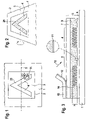
FIG. 1 shows a document,
FIG. 2 shows the document when tilted about an axis,
FIG. 3 shows a view in cross-section of a security element,
FIG. 4 shows the interface of a relief structure,
FIG. 5 shows a first observation condition,
FIG. 6 shows a second observation condition,
FIGS. 7 a and 7 b show the security element with grey stages, and
FIG. 8 shows a relief structure.
DESCRIPTION OF THE PREFERRED EMBODIMENTS
Referring to FIG. 1, reference 1 denotes a document, 2 denotes a security element, 3 a background surface, 4 a pattern element and 5 a notional tilt axis which is in the plane of the document 1. The document 1 is illuminated using directed artificial light laterally and inclinedly from above and is viewed perpendicularly from above. The security element 2 is fixed on the document 1. For identification purposes, the security element 2 has a pattern 25 comprising the pattern elements 4 which are surrounded by the background surfaces 3. In order to make the drawing in FIG. 1 clearer, the pattern 25 comprises a single pattern element 4 and forms a simple “V” sign. A practical embodiment involves the arrangement of a plurality of the background surfaces 3 and the pattern elements 4, with respect to the pattern 25. Under the specified illumination and observation conditions, the pattern 25 is not visible to an observer as there is no contrast between the pattern element 4 and the background surface 3, and both surfaces, both the background surface 3 and also the pattern element 4, appear dark, for example metallically matt. In diffuse daylight or in diffuse room lighting in contrast and under certain illumination conditions which are set forth hereinafter, the pattern element 4 stands out as being dark, from the light background surface 3, and is therefore clearly visible to the observer.
If, as shown in FIG. 2, the document 1 with the security element 2 is tilted about the tilt axis 5 in such a way that the background surface 3 reflects light into the eye of the observer, then the observer can recognise the pattern 25 as the pattern element 4 remains dark and stands out from the background surface 3, with a high level of contrast. Under that observation condition, the reflection condition for the observer is fulfilled. Rotation of the security element 2 in its plane does not change the appearance of the pattern 25 in the reflection condition, from the point of view of the observer, that is to say azimuthal orientation of the security element 2 is not to be implemented.
FIG. 3 shows the security element 2 (FIG. 2) in cross-section, wherein the section plane contains for example the tilt axis 5 (FIG. 2). The security element 2 comprises a layer composite or laminate 6 comprising a plurality of layers 7, 8, 9 and 11. Examples in regard to the structure of the laminate 6 and the materials used for same are to be found in EP 0 401 466 A1 and U.S. Pat. No. 4,856,857.
In the simplest case the laminate 6 includes at least a protective layer 7, an adhesive layer 8 and a lacquer layer 9 arranged between the protective layer 7 and the adhesive layer 8. The adhesive layer 8 joins the security element 2 to the document 1. An interface between the adhesive layer 8 and the lacquer layer 9 reflects light 10 which is incident through the cover layer 7 and the lacquer layer 9 if the refractive index at the boundary layer suddenly changes at the transition from the lacquer layer 9 to the adhesive layer 8. With the materials in Table 6 of U.S. Pat. No. 4, 856,857 the difference in the refractive indices is too small to achieve a strong reflection. The reflection capability is therefore increased by a reflection layer 11 which is arranged at the interface and which is a thin layer (<0.4 micrometer) comprising a metal or a metal coated with a suitable inorganic dielectric layer, the dielectric layer being arranged on the side of the metal, that is towards the incident light 10.
The materials for the reflection layer 11 are contained Table 1 to 5 of U.S. Pat. No. 4,856,857; Tables 1 to 6 are expressly incorporated into this description. Tellurium which is not mentioned in Table 5 is also suitable for the reflection layer 11. The incident light 10 means daylight or visually visible polychromatic light of wavelengths of between 380 nm and 780 nm.
In another embodiment of the laminate 6 the surface of the cover layer 7 of the laminate 6; that is remote from the lacquer layer 9, is connected to a carrier band or strip 13 by means of a separating layer 12 in order to facilitate transfer of the fragile laminate 6 onto the document 1. The carrier band 13 of paper or a plastic foil, for example PC or PETP can be removed after the laminate 6 has been glued in place so that the pattern 25 (FIG. 2) is visible through the protective layer 7 and the lacquer layer 9. In that respect attention is directed to GB 2 129 739 B which has already been referred to above.
As can be seen from FIG. 3 a relief structure 14 with a geometrical profile depth p is formed into the lacquer layer 9, in the region of the pattern elements 4. In the region of the background surfaces 3 the lacquer layer 9 is formed smooth and flat and is parallel to the other layers of the laminate 6. The material of the adhesive layer 8 fills the depressions of the relief structure 14. The interface with or without the additional reflection layer 11 follows both the relief structure 14 and also mirror planes of the background surfaces 3.
The relief structure 14 is a cross grating comprising two base gratings of periods d smaller than a limit wavelength λ at the short-wave end in the spectrum of visible light, that is to say between λ=380 nm and λ=420 nm and has an optically effective structure depth h, that is the profile depth p multiplied by the refractive index of the lacquer layer 9, preferably in the range of between h=50 nm and h=500 nm. Such relief structures 14 absorb almost all visible light 10 which is incident on the pattern elements 4 and scatter a small fraction of the incident light 10 back into the half-space above the pattern element 4. The percentage of the absorbed light 10 is non-linearly dependent on the structure depth h and can be controlled by means of the choice of the structure depth h in the above-mentioned range of between 50% and about 99%, in which respect the shallower the relief structure 14 the correspondingly more incident light 10 is scattered back and the correspondingly less light 10 is absorbed. The specified percentages apply for the relief structure 14 with a reflection layer 11 of for example aluminium. Adjoining regions of the pattern elements 4 with various structure depths h therefore exhibit a grey graduation.
The embodiment of the relief structure 14 which is shown in FIG. 4 is a cross grating formed by two sinusoidal base gratings which cross at a right angle. The sine function of the first base grating, which extends along the co-ordinate x, is of a period dx and an amplitude hx while the sine function of the second base grating which extends along the co-ordinate y is of a period dy and an amplitude hy. Over the plane defined by the co-ordinates x and y the interface h(x, y) formed by the cross grating in the laminate 6 (FIG. 3) follows for example the function:
h(x,y)=[h x +h y]·sin2 x/d x)·sin2y/d y).
Other embodiments involve h(x, y)=hx·sin2 (πx/dx)+hy·sin2(πy/dy), with rectangular or pyramid structures being used as the interface h(x, y).
In an embodiment the two periods dx, dy and the structure depths hx, hy are the same, while in other embodiments they are different. The structure depth h=[hx+hy] can be selected to be greater than the period d, but the relief structure 14 is difficult to produce, with the present-day manufacturing methods. The interface h(x, y) is like an egg carton and is shown in FIG. 4.
Referring to FIG. 5, the optical behaviour of the security element 2 with a first observation direction will now be discussed. The incident light 10 forms an angle of about 40° with the normal 15 to the plane of the security element 2. In an example the pattern elements 4 with the above-described relief structure 14 absorb in the visible range up to 95% of the incident light 10, the remainder is scattered. The reflective background surface 3 in contrast absorbs only about 10% of the incident light 10 and reflects the rest. As surface portions of the pattern elements 4 adjoin the reflective background surfaces 3, the observer therefore has such a strong contrast that the pattern elements 4 arranged on a predetermined background surface 3 of the security element 2 in the predetermined pattern 25 can be easily recognised as information. The pattern 25 represents a logo, a text, an image or another graphic character.
The drawing in FIG. 5 corresponds to the illumination conditions in the copier apparatus. Depending on the respective model of the copier apparatus, the directed light 10 of the copier apparatus which is incident on the document 1 and the security element 2, forms the angle of incidence α in the range of about 40° to 50° to the normal 15. The document 1 scatters the incident light 10 into the entire half-space. As a result scattered light passes into a light receiver 16 of the copier apparatus, which is arranged in the direction of the normal 15. In contrast thereto the light 17 which is reflected from the background surface 3 is deflected at the same angle α in accordance with the law of reflection into a viewing direction 18 of the observer 19 and does not pass into the light receiver 16. If the light 10 is incident on the pattern element 4 at the same angle of incidence α, the incident light 10 in contrast is practically absorbed; both the light receiver 16 and also the observer 19 register no light from the pattern element 4. The pattern element 4 is therefore dark.
The background surfaces 3 form the flat mirror surfaces of the pattern 25, for the light 10 which is incident in the laminate 6, while the pattern elements 4 as absorber surfaces swallow up the major part of the incident light 10. Therefore, in the reflected light 17, the observer 19 recognises the background surfaces 3 in the form of intensively light surface portions and the pattern elements 4 as dark surface portions of the pattern 25. In directions other than that of the reflected light 17, the security element 2 scatters only a small part of the incident light 10. The levels of intensity per unit of surface area of the light which is scattered at the background surfaces 3 and the pattern elements 4 are practically of the same magnitude so that there is no contrast between the background surfaces 3 and the pattern elements 4. In the case of illumination with the directedly incident light 10, the pattern 25 formed from the background surfaces 3 and the pattern elements 4 is recognisable only in the light 17 reflected with specular reflection, in contrast to a black-and-white image which is produced by a printing procedure.
In the copier apparatus the background surface 3 and the pattern element 4 projects such a small projection of the incident light 10 into the light receiver 16 that the copier apparatus indiscriminately reproduces the background field 3 and the pattern element 4 as black surfaces. The advantage of this security element 2 is that the copier apparatus cannot reproduce the information represented by the pattern element 4 while the observer 9 who, when using directedly incident light 10, almost automatically tilts the security element 2 in such a way that he views the background surface 3 in a reflection mode, can see the information of the pattern element 4 with a high level of contrast against the background surface 3. In that way the security element 2 can be easily distinguished by an attentive observer from reflecting metal foils on good coloured copies of the document 1. A further advantage is formed by the use of the relief structure 14 in the security element 2 with the periods dx (FIG. 4) and dy (FIG. 4) which are shorter than the wavelengths of the coherent light sources which can be used for holographic copying methods; it is therefore not possible to produce a copy of the security element 2 with the holographic methods.
FIG. 6 shows a second illumination condition for the two observers 19, 20 of the security element 2. A polychromatic radiation source 21, for example a halogen lamp, an incandescent lamp and so forth, is arranged above the second observer 20 and emits the incident light 10 onto the pattern element 4 at a large angle of incidence α of about 60° to 80°. The first observer 19 sees the pattern 25 (FIG. 2) of the pattern elements 4 in front of the background 3 (FIG. 5) at the reflection angle α, as referred to above. If the periods dx (FIG. 4), dy (FIG. 4) of the relief structure 14 are in the region of a half and whole limit wavelength λ; that is to say λ≧d≧λ/2, wherein d=dx or dy respectively, a part of the incident light 10 is deflected at a large diffraction angle β into the minus first order, as diffracted light 22. The second observer 20 can recognise the diffracted light 22. The diffracted light 22 includes the short-wave portion of the visually visible spectrum of the electromagnetic radiation. The diffracted light 22 is therefore dependent on the diffraction angle β and the periods dx, dy in a blue-green to violet colour. The colour of the diffracted light 22, which is observed at a predetermined diffraction angle β relative to the normal 15, is also dependent on the azimuth, in respect of its intensity. Note: in the foregoing consideration the refractive influence of the protective layer 7 has been disregarded.
In contrast, the first observer 19 is looking in the direction of the reflected light 17 and sees the background surfaces 3 as shinily bright surface portions and the pattern elements 4 as dark surface portions of the pattern 25.
If the period dx or dy is less than λ/2, the diffracted light 22 can no longer be seen by the second observer 20, in the direction of the co-ordinate x or y respectively, as the relief structure 14 no longer diffracts visible light 22. The first observer 19 who is observing the security element 2 at the reflection angle α sees the pattern elements 4 unchanged in a dark-brown to black colour, under these conditions.
The colour of the pattern elements 3 which are visible at the reflection angle α depends on the nature of the reflection layer 11 as various combinations of the materials in and at the reflection layer 11 do not uniformly reflect the incident light 10 in the entire spectral range of the visible electromagnetic radiation. Deep-black pattern elements 3 advantageously have a gradual transition in respect of the refractive index from the lacquer layer 9 to the reflection layer 11; the transition is produced by means of at least one layer of an inorganic dielectric 23 between the lacquer layer 9 and a metal layer 24 of the reflection layer 11. For the flat mirror surface of the background surfaces 3, the reflection layer 11 formed from the dielectric 23 and the metal layer 24 does not have a noticeable effect. In the case of the relief structure 14 in contrast, that reflection layer 11, as a consequence of interference phenomena, causes almost complete extinction of the incident light 10, which occurs in particular uniformly over the entire spectral range of the visible electromagnetic radiation. An example has a 50 nm thick layer of the dielectric 23 of ZnS and 100 nm of aluminium as the metal layer 24. A further advantage is the structure depth h which is increased by the high refractive index for ZnS of n=2.4, in relation to the refractive index of the lacquer layer 9 of n=1.5, with the profile depth p of the relief structure 14 remaining the same.
Besides the grey graduations with pattern elements 4 with different structure depths h the grey graduation in an embodiment of the security element 2 is produced by means of rastering of varying density, with raster dots of less than 0.4 nm in dimension. In that respect it is immaterial whether the raster dots are arranged as the background field 3 in a pattern element 4 or as the pattern element 4 in the background field 3.
FIGS. 7 a and 7 b show further examples for the production of grey stages or steps within a security element 2 from the dark pattern element 4 to the brightly shining background field 3. FIG. 7 a involves using raster dots of various sizes in a fixed raster of a maximum 0.5 mm spacing, corresponding to the grey stage. In a slightly lightened zone 26 the raster dots touch, in a lightened zone 27 the raster dots are of a mean dimension of about 0.25 mm while in a slightly darkened zone 28 the raster dots are about 0.15 mm. In FIG. 7 b, instead of the dot raster, there is a line raster with a maximum 0.5 mm spacing. A corresponding line width here affords the grey graduation in the zones 26 (FIG. 7 a) to 28 (FIG. 7 a).
In one of the zones 26 to 28 the raster dots of the pattern surfaces 4 are of the same dimensions. A very fine grey graduation is achieved by means of the suitably stepped structure depths h in the relief structures 14 (FIG. 6), which is adequate for the reproduction of a black-and-white photograph.
FIG. 8 shows two patterns 25 of the security element 2 as a simple example. In the upper half of the security element 2 the pattern 25 comprises a band 29 with a star 30. The band 29 is formed from the dark pattern element 4. The area around the band 29 and the star 30 form the light background surfaces 3. Without limitation in respect of the foregoing description, the background surfaces 3 and the pattern elements 4 are interchangeable, as is shown in the lower half of the security element 2.
The security element 2 in FIG. 1 will be still more difficult to counterfeit if the pattern 25 forms a background for a mosaic surface pattern 31 with diffraction structures who spatial frequencies are of values in the range of 300 lines per mm to 2000 lines per mm. Such mosaic surface patterns 31 are known from above-mentioned EP 0 105 099 A1, EP 0 330 738 A1 and EP 0 375 833 A1. The content of those patent specifications is hereby incorporated into this description.

Claims (13)

1. A security element with a pattern comprising surface portions and in the form of a laminate for authentication of a document, which includes at least a transparent protective layer, a transparent lacquer layer and an adhesive layer, wherein the lacquer layer is arranged between the protective layer and the adhesive layer and the refractive index abruptly changes at the interface between the adhesive layer and the lacquer layer and the surface portions of the pattern are composed of background surfaces and pattern elements,
wherein
in the region of the background surfaces the lacquer layer is smooth and flat in form and in the region of the pattern elements relief structures with a predetermined, optically effective structure depth are formed into the lacquer layer,
the background surfaces are flat mirror surfaces for light incident into the laminate, and
the relief structures are cross gratings formed from base gratings with periods and the periods are shorter than a predetermined limit wavelength at the short-wave end in the spectrum of visible light so that the pattern elements absorb and scatter the incident light, wherein in each relief structure the ratio of the absorbed and the scattered light is predeterminedly dependent on the optically effective structure depth prevailing in the relief structure.
2. A security element according to claim 1, wherein the cross grating of the relief structure is composed of two base gratings with the periods which are arranged substantially at a right angle relative to each other.
3. A security element according to claim 1, wherein the base gratings are sinusoidal.
4. A security element according to claim 1, wherein at least one of the periods is longer than half the limit wavelength but shorter than the limit wavelength.
5. A security element according to claim 1, wherein the limit wavelength is selected to be in the range of between 380 nm and 420 nm.
6. A security element according to claim 1, wherein the periods of the two base gratings are of the same value.
7. A security element according to claim 1, wherein the values for the optically effective structure depth of the relief structures are selected to be in the range of 50 nm to 500 nm.
8. A security element according to claim 1, wherein the reflection layer contains a metal from the group consisting of aluminum, silver, gold, chromium, copper, nickel and tellurium.
9. A security element according to claim 8, wherein the reflection layer, on the side of the metal layer that is towards the lacquer layer, has at least one layer of an inorganic dielectric.
10. A security element according to claim 9, wherein the layer of the inorganic dielectric comprises ZnS and the metal layer comprises aluminum.
11. A security element according to claim 1, wherein the pattern has zones with grey stages and that the pattern elements of the zones with various grey stages differ by the optically effective structure depth of the relief structures.
12. A security element according to claim 1, wherein the pattern has zones with grey stages, that the pattern elements have identical values with respect of to the optically effective structure depth and that the zones differ by rastering of varying density of raster dots of dimensions of less than 0.4 mm.
13. A security element according to claim 1, wherein the pattern forms a background for a mosaic surface pattern comprising diffraction structures with spatial frequencies in the range of 300 lines per mm to 2000 lines per mm.
US10/489,832 2001-10-12 2002-09-04 Security element Expired - Lifetime US7145723B2 (en)

Applications Claiming Priority (2)

Application Number Priority Date Filing Date Title
DE10150293A DE10150293B4 (en) 2001-10-12 2001-10-12 security element
PCT/EP2002/009861 WO2003033274A1 (en) 2001-10-12 2002-09-04 Security element

Publications (2)

Publication Number Publication Date
US20040239099A1 US20040239099A1 (en) 2004-12-02
US7145723B2 true US7145723B2 (en) 2006-12-05

Family

ID=7702235

Family Applications (1)

Application Number Title Priority Date Filing Date
US10/489,832 Expired - Lifetime US7145723B2 (en) 2001-10-12 2002-09-04 Security element

Country Status (16)

Country Link
US (1) US7145723B2 (en)
EP (1) EP1434695B1 (en)
JP (1) JP4315334B2 (en)
KR (1) KR100910098B1 (en)
CN (1) CN1268501C (en)
AT (1) ATE288364T1 (en)
AU (1) AU2002339482B2 (en)
CA (1) CA2462924C (en)
DE (2) DE10150293B4 (en)
ES (1) ES2236594T3 (en)
MY (1) MY126197A (en)
PL (1) PL202807B1 (en)
PT (1) PT1434695E (en)
RU (1) RU2255000C1 (en)
TW (1) TW542798B (en)
WO (1) WO2003033274A1 (en)

Cited By (7)

* Cited by examiner, † Cited by third party
Publication number Priority date Publication date Assignee Title
US20080094713A1 (en) * 2004-08-30 2008-04-24 Ovd Kinegram Ag Metallised Security Element
US9188716B2 (en) 2010-11-26 2015-11-17 Giesecke & Devrient Gmbh Reflective security element for security papers, value documents or the like
US9557461B2 (en) 2011-05-16 2017-01-31 Giesecke & Devrient Gmbh Two-dimensionally periodic, color-filtering grating
US9718297B2 (en) 2011-12-20 2017-08-01 Giesecke & Devrient Gmbh Security element for security papers, value documents or the like
US20170315277A1 (en) * 2015-01-15 2017-11-02 Toppan Printing Co., Ltd. Optical element, article, and method of producing optical element
EP2771724B1 (en) * 2011-10-28 2019-02-27 Surys Optical security component having a reflective effect, manufacture of said component, and secured document provided with such a component
US10682878B2 (en) 2014-07-31 2020-06-16 Giesecke+Devrient Currency Technology Gmbh Security element for producing value documents

Families Citing this family (60)

* Cited by examiner, † Cited by third party
Publication number Priority date Publication date Assignee Title
DE102004016596B4 (en) 2004-04-03 2006-07-27 Ovd Kinegram Ag Security element in the form of a multilayer film body and method for producing a security element
EP2631085B1 (en) 2004-04-30 2019-04-24 De La Rue International Limited Arrays of microlenses and arrays of microimages on transparent security substrates
JP4537164B2 (en) * 2004-09-30 2010-09-01 共同印刷株式会社 recoding media
DE102005017170B4 (en) * 2005-04-13 2010-07-01 Ovd Kinegram Ag Transfer film, process for their preparation and multilayer body and its use
DE102006016139A1 (en) * 2006-04-06 2007-10-18 Ovd Kinegram Ag Multi-layer body with volume hologram
JP2008134586A (en) * 2006-10-23 2008-06-12 Toppan Printing Co Ltd Display element and display body
JP4961944B2 (en) 2006-10-24 2012-06-27 凸版印刷株式会社 Display and printed matter
FR2908223B1 (en) 2006-11-07 2008-12-26 Hologram Ind Sarl METHOD FOR MANUFACTURING SECURE PROTECTIVE FILMS AND RELATED FILMS FOR THE PROTECTION OF IDENTITY DOCUMENTS
DE602007009719D1 (en) * 2006-12-07 2010-11-18 Agfa Gevaert Nv METHOD FOR PRODUCING AN INFORMATION SUPPORT
DE102007005884B4 (en) * 2007-02-07 2022-02-03 Leonhard Kurz Stiftung & Co. Kg security document
JP2008275740A (en) * 2007-04-26 2008-11-13 Toppan Printing Co Ltd Display body and laminate
CA2686460C (en) 2007-05-25 2012-05-01 Toppan Printing Co., Ltd. Display and information-printed matter
DE102007029203A1 (en) * 2007-06-25 2009-01-08 Giesecke & Devrient Gmbh security element
CA2692949C (en) * 2007-09-28 2013-03-12 Toppan Printing Co., Ltd. Display and labeled article
JP5176529B2 (en) * 2007-12-17 2013-04-03 凸版印刷株式会社 Display, adhesive label, transfer foil, and labeled article
JP5266770B2 (en) * 2008-01-22 2013-08-21 凸版印刷株式会社 Display body and labeled article comprising relief structure forming layer
JP5272438B2 (en) * 2008-02-19 2013-08-28 凸版印刷株式会社 Display and labeled goods
JP5251169B2 (en) * 2008-03-05 2013-07-31 凸版印刷株式会社 Verification device and article to be verified using the device
JP5245521B2 (en) * 2008-04-30 2013-07-24 凸版印刷株式会社 Display body and printed information using the same
JP5515244B2 (en) * 2008-07-04 2014-06-11 凸版印刷株式会社 Display and labeled goods
JP5338177B2 (en) * 2008-07-31 2013-11-13 凸版印刷株式会社 Display and labeled goods
EP3236299A1 (en) 2008-09-05 2017-10-25 Viavi Solutions Inc. An optical device exhibiting color shift upon rotation
JP2010078821A (en) * 2008-09-25 2010-04-08 Toppan Printing Co Ltd Display body, adhesive label, and labeled article
US9993895B2 (en) 2009-03-30 2018-06-12 Boegli-Gravures Sa Method and device for structuring the surface of a hard material coated solid body by means of a laser
RU2573160C2 (en) * 2009-03-30 2016-01-20 Боэгли-Гравюр С.А. Method and device for structuring of surface of solid body coated with solid material with help of laser
JP2011002749A (en) * 2009-06-22 2011-01-06 Toppan Printing Co Ltd Security film and transfer foil
JP5504732B2 (en) * 2009-07-30 2014-05-28 凸版印刷株式会社 Display and labeled goods
JP5564940B2 (en) * 2009-12-25 2014-08-06 大日本印刷株式会社 Hologram label
CN103124641B (en) * 2010-09-29 2015-12-09 巴斯夫欧洲公司 Safety element
DE102010050031A1 (en) 2010-11-02 2012-05-03 Ovd Kinegram Ag Security element and method for producing a security element
DE102010050895A1 (en) * 2010-11-10 2012-05-10 Giesecke & Devrient Gmbh Thin-film element with multilayer structure
JP2012123102A (en) * 2010-12-07 2012-06-28 Toppan Printing Co Ltd Display body and labeled article
JP5741125B2 (en) * 2011-03-29 2015-07-01 凸版印刷株式会社 Display and labeled goods
JP2013092683A (en) * 2011-10-26 2013-05-16 Toppan Printing Co Ltd Image display body, manufacturing method of image display body and information medium
AU2011101567B4 (en) * 2011-11-30 2012-08-09 Innovia Security Pty Ltd Diffractive device
BR112014029710A2 (en) * 2012-06-01 2018-04-17 Toppan Printing Co., Ltd. An information storage object using an unisometric reflection display body and an unisometric reflection display body
DE102012014414A1 (en) 2012-07-20 2014-01-23 Giesecke & Devrient Gmbh Security element for security papers, documents of value or the like
DE102013002137A1 (en) * 2013-02-07 2014-08-07 Giesecke & Devrient Gmbh Optically variable surface pattern
DE102013009972A1 (en) 2013-06-14 2014-12-18 Giesecke & Devrient Gmbh security element
EP3041786A1 (en) * 2013-09-02 2016-07-13 Danmarks Tekniske Universitet A nanostructured surface for grey scale colouring
CN104647935B (en) * 2013-11-22 2016-08-17 中钞特种防伪科技有限公司 Optical anti-counterfeit element and manufacture method thereof
DE102014004941A1 (en) 2014-04-04 2015-10-08 Giesecke & Devrient Gmbh Security element for security papers, documents of value or the like
DE102014018551A1 (en) 2014-12-15 2016-06-16 Giesecke & Devrient Gmbh value document
CN107111022B (en) * 2015-01-08 2020-05-12 凸版印刷株式会社 Display body and article
JP5994899B2 (en) * 2015-04-30 2016-09-21 凸版印刷株式会社 Display and labeled goods
DE102015106800B4 (en) * 2015-04-30 2021-12-30 Leonhard Kurz Stiftung & Co. Kg Method for producing a multilayer body
CN107850708B (en) 2015-07-15 2022-03-22 凸版印刷株式会社 Display body
JP6676951B2 (en) 2015-07-15 2020-04-08 凸版印刷株式会社 Display body
DE102015016751A1 (en) 2015-12-23 2017-06-29 Giesecke & Devrient Gmbh Security element for security papers, documents of value or the like
US11167582B2 (en) * 2016-02-09 2021-11-09 Toppan Printing Co., Ltd. Optical element and information recording medium for counterfeit prevention
KR20170003255U (en) 2016-03-10 2017-09-20 주식회사 에코웰 Portable Discharge Apparatus Of Cosmetic
GB2555491B (en) 2016-11-01 2019-03-27 De La Rue Int Ltd Security devices and methods of manufacture thereof
DE102017003281A1 (en) 2017-04-04 2018-10-04 Giesecke+Devrient Currency Technology Gmbh Security element with relief structure and manufacturing method therefor
DE102017003274A1 (en) 2017-04-04 2018-10-04 Giesecke+Devrient Currency Technology Gmbh Security element and manufacturing method therefor
TWI674216B (en) 2017-04-14 2019-10-11 溫芫鋐 Mechanical brake caliper for a bicycle
CN107622728A (en) * 2017-08-31 2018-01-23 苏州印象镭射科技有限公司 For producing the micro-structural and secure ID of diffraction code
DE102018003030A1 (en) * 2018-04-13 2019-10-17 Giesecke+Devrient Currency Technology Gmbh Security element, method for producing the same and equipped with the security element disk
CN110857003B (en) * 2018-08-23 2020-12-25 中钞特种防伪科技有限公司 Optical anti-counterfeiting element, design method thereof and anti-counterfeiting product
WO2021151459A1 (en) * 2020-01-27 2021-08-05 Orell Füssli AG Security document with lightguide having a sparse outcoupler structure
DE102021106085A1 (en) 2021-03-12 2022-09-15 Leonhard Kurz Stiftung & Co. Kg Transfer film, a method of manufacturing a transfer film and a method of manufacturing a plastic article decorated with a transfer film

Citations (12)

* Cited by examiner, † Cited by third party
Publication number Priority date Publication date Assignee Title
EP0105099A1 (en) 1982-10-04 1984-04-11 LGZ LANDIS &amp; GYR ZUG AG Document with diffractive security pattern
GB2129739A (en) 1982-11-08 1984-05-23 American Bank Note Co Processes and products for reproducing light diffracting patterns
US4856857A (en) 1985-05-07 1989-08-15 Dai Nippon Insatsu Kabushiki Kaisha Transparent reflection-type
EP0330738A1 (en) 1988-03-03 1989-09-06 Landis &amp; Gyr Betriebs AG Document
EP0375833A1 (en) 1988-12-12 1990-07-04 Landis &amp; Gyr Technology Innovation AG Optically variable planar pattern
EP0401466A1 (en) 1989-06-05 1990-12-12 Landis &amp; Gyr Technology Innovation AG Laminate with diffraction structures
EP0522217B1 (en) 1991-07-10 1995-09-06 Banque De France Fiduciary document or security document bearing an anti-forgery device and process for the manufacture of such a document
DE4410431A1 (en) 1994-03-25 1995-09-28 Giesecke & Devrient Gmbh ID card protected against unauthorized reproduction with a copier
US5737886A (en) 1996-04-04 1998-04-14 Kruckemeyer; Robert J. Method for determining forgeries and authenticating signatures
US6369919B1 (en) * 1998-05-14 2002-04-09 De La Rue International Limited Holographic security device
US20050270604A1 (en) * 2000-07-18 2005-12-08 Optaglio Limited Diffractive device
US7054042B2 (en) * 2000-06-28 2006-05-30 De La Rue International Limited Optically variable security device

Family Cites Families (6)

* Cited by examiner, † Cited by third party
Publication number Priority date Publication date Assignee Title
KR100247850B1 (en) 1993-03-20 2000-06-01 토니올로 쿠르트 Security device, embossing table for security device and the preparation method of security device
GB9509487D0 (en) * 1995-05-10 1995-07-05 Ici Plc Micro relief element & preparation thereof
JPH09220892A (en) * 1996-02-19 1997-08-26 Toppan Printing Co Ltd Hologram pattern intended for anticopying and article applied therewith
JPH1010956A (en) 1996-06-24 1998-01-16 Toppan Printing Co Ltd Diffraction grating pattern, certification method of the sane, and article utilizing diffraction grating pattern
JPH10332916A (en) * 1997-05-30 1998-12-18 Toppan Printing Co Ltd Diffraction grating pattern
US6761959B1 (en) 1999-07-08 2004-07-13 Flex Products, Inc. Diffractive surfaces with color shifting backgrounds

Patent Citations (16)

* Cited by examiner, † Cited by third party
Publication number Priority date Publication date Assignee Title
US4568141A (en) 1982-10-04 1986-02-04 Lgz Landis & Gyr Zug Ag Document having an optical-diffraction authenticating element
EP0105099A1 (en) 1982-10-04 1984-04-11 LGZ LANDIS &amp; GYR ZUG AG Document with diffractive security pattern
GB2129739A (en) 1982-11-08 1984-05-23 American Bank Note Co Processes and products for reproducing light diffracting patterns
US4856857A (en) 1985-05-07 1989-08-15 Dai Nippon Insatsu Kabushiki Kaisha Transparent reflection-type
US4984824A (en) 1988-03-03 1991-01-15 Lgz Landis & Gyr Zug Ag Document with an optical diffraction safety element
EP0330738A1 (en) 1988-03-03 1989-09-06 Landis &amp; Gyr Betriebs AG Document
US5032003A (en) 1988-12-12 1991-07-16 Landis & Gyr Betriebs Ag Optially variable surface pattern
EP0375833A1 (en) 1988-12-12 1990-07-04 Landis &amp; Gyr Technology Innovation AG Optically variable planar pattern
EP0401466A1 (en) 1989-06-05 1990-12-12 Landis &amp; Gyr Technology Innovation AG Laminate with diffraction structures
US5104471A (en) * 1989-06-05 1992-04-14 Landis & Gyr Betriebs Ag Interlaminar sandwich with diffraction structure
EP0522217B1 (en) 1991-07-10 1995-09-06 Banque De France Fiduciary document or security document bearing an anti-forgery device and process for the manufacture of such a document
DE4410431A1 (en) 1994-03-25 1995-09-28 Giesecke & Devrient Gmbh ID card protected against unauthorized reproduction with a copier
US5737886A (en) 1996-04-04 1998-04-14 Kruckemeyer; Robert J. Method for determining forgeries and authenticating signatures
US6369919B1 (en) * 1998-05-14 2002-04-09 De La Rue International Limited Holographic security device
US7054042B2 (en) * 2000-06-28 2006-05-30 De La Rue International Limited Optically variable security device
US20050270604A1 (en) * 2000-07-18 2005-12-08 Optaglio Limited Diffractive device

Cited By (9)

* Cited by examiner, † Cited by third party
Publication number Priority date Publication date Assignee Title
US20080094713A1 (en) * 2004-08-30 2008-04-24 Ovd Kinegram Ag Metallised Security Element
US7907339B2 (en) 2004-08-30 2011-03-15 Ovd Kinegram Ag Metallised security element
US9188716B2 (en) 2010-11-26 2015-11-17 Giesecke & Devrient Gmbh Reflective security element for security papers, value documents or the like
US9557461B2 (en) 2011-05-16 2017-01-31 Giesecke & Devrient Gmbh Two-dimensionally periodic, color-filtering grating
EP2771724B1 (en) * 2011-10-28 2019-02-27 Surys Optical security component having a reflective effect, manufacture of said component, and secured document provided with such a component
US9718297B2 (en) 2011-12-20 2017-08-01 Giesecke & Devrient Gmbh Security element for security papers, value documents or the like
US10682878B2 (en) 2014-07-31 2020-06-16 Giesecke+Devrient Currency Technology Gmbh Security element for producing value documents
US20170315277A1 (en) * 2015-01-15 2017-11-02 Toppan Printing Co., Ltd. Optical element, article, and method of producing optical element
US10649120B2 (en) * 2015-01-15 2020-05-12 Toppan Printing Co., Ltd. Optical element, article, and method of producing optical element

Also Published As

Publication number Publication date
JP4315334B2 (en) 2009-08-19
MY126197A (en) 2006-09-29
ES2236594T3 (en) 2005-07-16
WO2003033274A1 (en) 2003-04-24
KR20040051601A (en) 2004-06-18
CN1568264A (en) 2005-01-19
PT1434695E (en) 2005-04-29
JP2005518956A (en) 2005-06-30
US20040239099A1 (en) 2004-12-02
AU2002339482B2 (en) 2006-12-07
PL202807B1 (en) 2009-07-31
CA2462924C (en) 2008-11-04
DE10150293A1 (en) 2003-04-30
PL367433A1 (en) 2005-02-21
RU2255000C1 (en) 2005-06-27
CN1268501C (en) 2006-08-09
KR100910098B1 (en) 2009-07-30
EP1434695A1 (en) 2004-07-07
DE10150293B4 (en) 2005-05-12
TW542798B (en) 2003-07-21
EP1434695B1 (en) 2005-02-02
RU2004114260A (en) 2005-03-27
CA2462924A1 (en) 2003-04-24
ATE288364T1 (en) 2005-02-15
DE50202189D1 (en) 2005-03-10

Similar Documents

Publication Publication Date Title
US7145723B2 (en) Security element
US9465148B2 (en) Security document
US10525758B2 (en) Security element, value document comprising such a security element, and method for producing such a security element
RU2339524C2 (en) Printing film for production of tamper-proof number plates and tamper-proof number plate containing printing film
US5808758A (en) Data carrier with an optically variable element
CN101484323B (en) Security device
US6801346B2 (en) Diffractive safety element
US7144617B2 (en) Diffractive security element
US5403040A (en) Optically variable and machine-readable device for use on security documents
RU2286887C2 (en) Method for using protective element as protection from photo-copying
EP0746472A1 (en) Diffractive device with enhanced anti-copying protection
JPH1081060A (en) Duplication preventing medium and manufacture thereof
JP2008107383A (en) Gonio-chromatic element and display material using the same
JPH1081058A (en) Duplication preventing medium and manufacture thereof
AU679333B2 (en) Diffractive device with enhanced anti-copying protection
JPH1081059A (en) Duplication preventing medium and manufacture thereof
JPH1081055A (en) Duplication preventing medium
JPH1081057A (en) Duplication preventing medium and manufacture thereof

Legal Events

Date Code Title Description
AS Assignment

Owner name: OVD KINEGRAM AG, SWITZERLAND

Free format text: ASSIGNMENT OF ASSIGNORS INTEREST;ASSIGNORS:STAUB, RENE;TOMPKIN, WAYNE ROBERT;SCHILLING, ANDREAS;REEL/FRAME:015611/0710

Effective date: 20040304

STCF Information on status: patent grant

Free format text: PATENTED CASE

CC Certificate of correction
FEPP Fee payment procedure

Free format text: PAYOR NUMBER ASSIGNED (ORIGINAL EVENT CODE: ASPN); ENTITY STATUS OF PATENT OWNER: LARGE ENTITY

FPAY Fee payment

Year of fee payment: 4

FPAY Fee payment

Year of fee payment: 8

MAFP Maintenance fee payment

Free format text: PAYMENT OF MAINTENANCE FEE, 12TH YEAR, LARGE ENTITY (ORIGINAL EVENT CODE: M1553)

Year of fee payment: 12