US7163117B2 - Static charge dissipater for filler neck closure - Google Patents
Static charge dissipater for filler neck closure Download PDFInfo
- Publication number
- US7163117B2 US7163117B2 US10/427,388 US42738803A US7163117B2 US 7163117 B2 US7163117 B2 US 7163117B2 US 42738803 A US42738803 A US 42738803A US 7163117 B2 US7163117 B2 US 7163117B2
- Authority
- US
- United States
- Prior art keywords
- coating
- conductive
- fuel cap
- cover
- filler neck
- Prior art date
- Legal status (The legal status is an assumption and is not a legal conclusion. Google has not performed a legal analysis and makes no representation as to the accuracy of the status listed.)
- Expired - Fee Related, expires
Links
Images


Classifications
-
- B—PERFORMING OPERATIONS; TRANSPORTING
- B60—VEHICLES IN GENERAL
- B60K—ARRANGEMENT OR MOUNTING OF PROPULSION UNITS OR OF TRANSMISSIONS IN VEHICLES; ARRANGEMENT OR MOUNTING OF PLURAL DIVERSE PRIME-MOVERS IN VEHICLES; AUXILIARY DRIVES FOR VEHICLES; INSTRUMENTATION OR DASHBOARDS FOR VEHICLES; ARRANGEMENTS IN CONNECTION WITH COOLING, AIR INTAKE, GAS EXHAUST OR FUEL SUPPLY OF PROPULSION UNITS IN VEHICLES
- B60K15/00—Arrangement in connection with fuel supply of combustion engines or other fuel consuming energy converters, e.g. fuel cells; Mounting or construction of fuel tanks
- B60K15/03—Fuel tanks
- B60K15/04—Tank inlets
- B60K15/0406—Filler caps for fuel tanks
-
- B—PERFORMING OPERATIONS; TRANSPORTING
- B60—VEHICLES IN GENERAL
- B60K—ARRANGEMENT OR MOUNTING OF PROPULSION UNITS OR OF TRANSMISSIONS IN VEHICLES; ARRANGEMENT OR MOUNTING OF PLURAL DIVERSE PRIME-MOVERS IN VEHICLES; AUXILIARY DRIVES FOR VEHICLES; INSTRUMENTATION OR DASHBOARDS FOR VEHICLES; ARRANGEMENTS IN CONNECTION WITH COOLING, AIR INTAKE, GAS EXHAUST OR FUEL SUPPLY OF PROPULSION UNITS IN VEHICLES
- B60K15/00—Arrangement in connection with fuel supply of combustion engines or other fuel consuming energy converters, e.g. fuel cells; Mounting or construction of fuel tanks
- B60K15/03—Fuel tanks
- B60K2015/03328—Arrangements or special measures related to fuel tanks or fuel handling
- B60K2015/03401—Arrangements or special measures related to fuel tanks or fuel handling for preventing electrostatic charges
-
- Y—GENERAL TAGGING OF NEW TECHNOLOGICAL DEVELOPMENTS; GENERAL TAGGING OF CROSS-SECTIONAL TECHNOLOGIES SPANNING OVER SEVERAL SECTIONS OF THE IPC; TECHNICAL SUBJECTS COVERED BY FORMER USPC CROSS-REFERENCE ART COLLECTIONS [XRACs] AND DIGESTS
- Y10—TECHNICAL SUBJECTS COVERED BY FORMER USPC
- Y10S—TECHNICAL SUBJECTS COVERED BY FORMER USPC CROSS-REFERENCE ART COLLECTIONS [XRACs] AND DIGESTS
- Y10S220/00—Receptacles
- Y10S220/33—Gasoline tank cap
Definitions
- the present disclosure relates to a fuel cap, and particularly to a fuel cap for closing a vehicle fuel tank filler neck. Specifically, the present disclosure relates to an electrically conductive fuel cap which dissipates static charge.
- Fuel caps and fuel components of various types have been made conductive to dissipate static charges. It is known, for example, to mold plastic components with conductive carbon black particles mixed into resin from which the component is molded. It has also been suggested that a conductive coating may be applied to a fuel cap component, for example, by coating the component with an epoxy resin containing conductive particles. See for example U.S. Pat. No. 6,003,709, col. 3, lines 2–20.
- the present invention comprises one or more of the following features or combinations thereof.
- a fuel cap is provided with a cover molded from a plastic resin, typically a nylon or acetal, to form an outer shell.
- This shell may be molded from a non-conductive resin and then coated at least in part with a conductive coating.
- a conductive coating For example, in some cases, only the outer gripping surface of the shell may be coated, and in other cases, all or substantially all of its surfaces may be coated.
- the coating should be sufficiently conductive to discharge a static charge built up by the operator.
- the conductive coating will be coupled to the conductive filler neck or a conductive portion of the vehicle body near or adjacent to the filler neck.
- thermosetting resin a thermosetting resin
- thermoplastic resin a thermoplastic resin
- conductive particles a coating normally supplied for use as a pre-coating or as an adhesion promoter has been found to have excellent characteristics as the primary or only coating for a fuel cap shell.
- FIG. 1 is a sectional view of a fuel cap of the present disclosure showing the fuel cap including a handle or cover having a resin shell and an electrically conductive outer coating applied thereon, a housing coupled to the handle, and a plug tether, made of a conductive material, coupled to and positioned within the handle for contact with the conductive coating;
- FIG. 2 is a perspective view of an illustrative fuel-receiving assembly for engagement with the fuel cap;
- FIG. 3 is a sectional view of another fuel cap in accordance with the present disclosure showing the fuel cap including a cover having a resin shell and the electrically conductive outer coating applied thereon, a housing coupled to the cover, and a ring tether made of a conductive material and forming an outer ring around the cover;
- FIG. 4 is a sectional view of another fuel cap in accordance with the present disclosure showing the fuel cap including a cover having a resin shell and an electrically conductive coating deposited on both an outer surface and an inner surface of the resin shell, a housing made of a conductive material coupled to the cover, and a plug tether coupled to the cover;
- FIG. 5 is a sectional view of yet another fuel cap in accordance with the present disclosure showing the fuel cap including a cover having a resin shell and the electrically conductive coating deposited on the outer and inner surfaces of the shell, a housing made of a conductive material coupled to the cover, and a ring tether made of a conductive material coupled to the cover;
- FIG. 6 is a sectional view of still another fuel cap in accordance with the present disclosure showing the fuel cap including a cover having a resin shell and the electrically conductive coating deposited on the outer surface of the shell, a housing made of a conductive material coupled to the cover, and a retainer ring made of a conductive material and engaged with both the conductive coating on the outer surface of the shell and the housing;
- FIG. 7 is a flow chart illustrating a conductive coating process for coating a fuel cap in accordance with the present disclosure
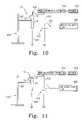
- FIGS. 8–11 are diagrammatic views illustrating a laboratory test for applying a high voltage to a fuel cap having an electrically conductive outer coating to measure the decay rate or dissipation of the charge applied to the fuel cap;
- FIG. 12 is a graph showing the decay rate of an illustrative fuel cap in accordance with the present disclosure.
- a fuel cap 10 shown in FIG. 1 , is provided for use with an illustrative fuel-receiving assembly, such as assembly 13 shown in FIG. 2 .
- a portion of the fuel cap 10 includes a handle or cover 16 including a non-conductive body portion or resin shell 32 , such as nylon, for example, and an electrically conductive outer coating 34 deposited on the shell 32 to provide a means for static charge dissipation.
- the illustrative coating 34 is sufficiently conductive to dissipate a static charge built up by an operator, for example, as the operator grasps the cover 16 to remove the fuel cap 10 from the fuel-receiving assembly 13 prior to refueling.
- the fuel-receiving assembly 13 includes a fuel tank filler neck 14 and a tank filler neck insert 12 on an open end 17 thereof.
- the fuel cap 10 is engageable with the fuel-receiving assembly 13 to close and seal an open mouth or fuel port 11 of tank filler neck insert 12 .
- Tank filler neck insert 12 is made of an electrically conductive plastics material or any other electrically conductive material such as metal, for example.
- Fuel tank 19 is of known construction and as such is shown diagrammatically in FIG. 2 . Electrically conductive portions of fuel-receiving assembly 13 are normally grounded through the vehicle (not shown). As mentioned above, portions of fuel cap 10 are also made of an electrically conductive material, specifically, an electrically conductive coating 34 .
- the fuel cap 10 When installed in the fuel-receiving assembly 13 , the fuel cap 10 is electrically grounded through the vehicle by an electrically conductive discharge member 15 coupled at one end to fuel cap 10 to engage the conductive coating 34 and coupled at another end to a portion of the vehicle, as is discussed in greater detail below.
- a fuel cap in accordance with the present disclosure is configured to “ground” a person touching the fuel cap prior to removal of the fuel cap from the filler neck 14 so as to dissipate to ground, in a controlled manner, any electrostatic charge or potential on the person at the outset of a vehicle refueling cycle and before fuel vapor is allowed to vent through the mouth 11 of the filler neck 14 .
- Illustrative fuel caps are disclosed in PCT International Publication No. WO 99/05026 entitled “Fuel Cap” and in U.S. Pat. No. 6,508,374 entitled “Filler Neck Closure with Static Charge Dissipater”, issued Jan. 21, 2003, the disclosures of each of which are hereby incorporated by reference herein.
- fuel cap 10 includes a cover 16 and a housing or fuel port closure 18 coupled at a first end to and positioned under cover 16 .
- Fuel port closure 18 is a quick-on type closure and is normally received within filler neck insert 12 of assembly 13 .
- Fuel cap 10 further includes a tether 15 coupled to and received within handle 16 . Tether 15 acts as the discharge member of fuel cap 10 to provide an electrically conductive path between the fuel cap 10 and a grounded portion of the vehicle through which any static charge may dissipate.
- Illustrative tether 15 is a plug tether including a first end 20 received within an aperture 30 of cover 16 and a second end 22 .
- Second end 22 of tether 15 may be coupled to either a body portion (not shown) of the vehicle or to a portion of fuel-receiving assembly 13 .
- the body portion (not shown) of the vehicle to which the second end 22 of tether 15 may be coupled is an electrically conductive body portion, such as an assembly closure door (not shown), for example.
- Tether 15 also acts to couple fuel cap 10 to the vehicle (not shown) to prevent a user, for example, from misplacing fuel cap 10 during a fuel tank refueling period.
- Tether 15 is molded from an electrically conductive material.
- Illustrative tether 15 is made of a thermoplastic elastomer having conductive particles provided throughout. Such conductive particles may be carbon black particles, stainless steel powder or fibers, and/or Perma-Stat® particles. Stainless steel powder or fiber particles are available through RTP, Co. of Wynona, Minn. (hereinafter “RTP”) and Ticona of Summit, N.J., for example. The Perma-Stat® particles are also available through RTP.
- illustrative tether 15 is made of a thermoplastic elastomer having conductive particles, tether 15 may also be made of other plastics such as nylon having conductive particles provided therein, for example. Further, tether 15 may be made of metal and may be a metal chain, for example. In other words, tether 15 may be made of various materials such that tether 15 is electrically conductive.
- first end 20 of tether 15 is coupled to cover 16 .
- Second end 22 of tether 15 is coupled to an electrically conductive portion of the vehicle (not shown). Therefore, tether 15 is a discharge member for dissipating static charge from an operator grabbing handle 16 of fuel cap 10 to the conductive body of the vehicle in order to prevent any electrostatic charge or potential on the operator from igniting fuel vapor vented through the mouth 11 of the filler neck 14 .
- Tether 15 provides a conductive path between illustrative electrically conductive fuel cap 10 and the vehicle to fully ground the fuel cap 10 and operator grasping the fuel cap 10 prior to breaking a sealed connection at O-ring seal 21 between closure member 18 and filler neck insert 12 during removal of cap 10 from filler neck 14 prior to refueling the fuel tank 19 .
- Any static charge carried by the operator therefore, is discharged before any fuel vapors escape from within assembly 13 to potentially be ignited by such a static charge.
- Shell 32 of handle 16 is made of an electrically non-conductive resin or plastics material.
- Illustrative non-conductive plastics material 32 is a nylon resin such as Nylon 66 made by E.I. DuPont de Nemours & Co. (hereinafter “DuPont”), of Wilmington, Del. or Nylon 6 made by RTP.
- nylon resin is injection molded to form the resin shell 32 of handle 16 .
- the resin shell 32 of cover 16 is molded from a nylon resin, it is within the scope of this disclosure to mold the resin shell 32 cover 16 from any type of polyamide resin or another material such as acetal, for example.
- Cover 16 further includes electrically conductive outer coating 34 applied to an outer surface 24 of the nylon resin shell 32 .
- Illustrative conductive coating 34 is approximately 0.2–0.4 mil thick and includes a thermosetting resin, a thermoplastic resin, and conductive particles.
- coating 34 includes a particulate conductor dispersed in a solid polymer matrix comprising a covalently cross-linked thermoset polymer and a non-covalently cross-linked thermoplastic polymer.
- the particulate conductor will be a micro-particulate conductor.
- the conductive coating 34 may range from about 0.1 mil to 0.6 mil thick.
- cover 16 having an electrically conductive coating, such as coating 34 , with any suitable thickness so as to maintain sufficient durability and wearability standards as well as ensure a suitable dissipation rate of a typical static charge carried by an operator, for example.
- coating 34 is formed by applying a coating composition (not shown) comprising the thermosetting resin, the thermoplastic resin, and the conductive particles in a solvent solution.
- This coating composition is atomized and then sprayed onto outer surface 24 of resin shell 32 .
- it is within the scope of this disclosure to apply the coating using other suitable means such as through the use of an electrostatic sprayer or via vacuum deposition, for example.
- the thermosetting resin is an alkyd resin
- the thermoplastic resin is a chlorinated polyoleffin
- the conductive particles are carbon black particles.
- the carbon black particles typically make up approximately 1% to 10% of the conductive coating 34 .
- the illustrative conductive particles of the coating are carbon black particles, it is within the scope of this disclosure for the conductive particles to be any other suitable conductive particles such as, for example, stainless steel powder or fiber particles and/or Perma-Static®, for example.
- Illustrative conductive coating 34 coupled to shell 32 is product number 764-2592 Adhesion Promoter made by DuPont.
- This product (764-2592) is a high solids conductive adhesion promoter designed to promote adhesion between olefin plastics and primers or high solids basecoat/clearcoat systems.
- Dupont's adhesion promoter is used as a basecoat for various olefinic plastic objects prior to applying another coating, such as paint, for example, to the object.
- the electrically conductive adhesion promoter or coating 34 therefore, is used as a pre-coat and allows a final coat of paint to be electrostatically sprayed onto a plastic object. Additional information relating to the coating of the present disclosure and properties thereof are contained in the attached material data sheets found in Appendix A.
- Coating 34 is generally black or gray in color typically because of the carbon black particles present therein.
- Nylon resin shell 32 is generally black or gray in color as well. Therefore, application of coating 34 to resin shell 32 does not appreciably change the appearance of shell 32 . As shown in FIG. 1 , coating 34 is applied to outer surface 24 of resin shell 32 .
- Housing 18 of fuel cap 10 is made of a non-conductive material such as acetal, for example. Housing 18 (including a threaded portion 23 ) is insertable into filler neck insert 12 to retain cap 10 in a closed position to cover fuel port 11 . Housing 18 is sized and dimensioned to engage at least a portion of an internal surface 25 of the insert 12 of fuel-receiving assembly 13 .
- Such means for dissipating an electrical charge through cap 10 includes the conductive coating 34 coated onto the nylon resin shell 32 of cover 16 and the conductive tether 15 coupled to cover 16 and engaged with conductive coating 34 of cover 16 . These components define a common electrically conductive path facilitating and establishing a common electrical potential.
- conductive tether 15 is coupled at first end 20 to cover 16 and may be coupled at second end 22 to either an electrically conductive body portion (not shown) of the vehicle (not shown) or to filler neck insert 12 of fuel-receiving assembly 13 , which, as mentioned above, is grounded through the vehicle.
- tether 15 acts as a discharge member to dissipate a static charge carried by the operator, for example, from the fuel cap 10 to ground.
- fuel cap 110 is provided for use with a fuel-receiving assembly, such as assembly 13 , for example.
- fuel cap 110 is similar to fuel cap 10 and includes a cover 116 having non-conductive, nylon resin body 32 and the conductive outer coating 34 , discussed above and in Appendix A, coupled to the resin shell 32 .
- conductive coating 34 is applied to an outer surface 117 of resin shell 32 .
- Fuel cap 110 also includes a threaded profile housing or fuel port closure 118 coupled at a first end to and positioned under the handle 116 as well as a retainer 120 arranged to couple or support cover 116 on housing 118 . Retainer 120 may also permit lost motion between handle 116 and fuel port closure 118 .
- Fuel cap 110 also includes a ring tether 115 coupled to cover 116 .
- Illustrative ring tether 115 is positioned within a notch 122 of cover 116 defined by first and second rims 124 , 126 of cover 116 .
- Tether 115 is also supported by the retainer 120 .
- Tether 115 includes a generally ring-shaped portion 128 to fit around handle 116 and within notch 122 and a leash portion 130 (shown diagrammatically in FIG. 3 ) coupled to ring-shaped portion 128 .
- Leash portion 130 is coupled at a first end 132 to ring-shaped portion 128 and is illustratively coupled at a second end 134 to a conductive body portion 140 (also shown diagrammatically in FIG. 3 ) of the vehicle (not shown).
- tether 115 may also be coupled to filler neck 12 of assembly 13 in order to establish a grounded connection for cover 116 .
- tether 115 may be made from the same materials as those discussed above with respect to tether 15 .
- Tether 115 is conductive and, therefore, acts as a discharge member for fuel cap 10 .
- Tether 115 is in contact with conductive coating 34 of cover 16 . Therefore, any static charge carried on an operator is dissipated through the conductive coating 34 of the handle (grasped by the user) and along the discharge member or tether 115 to either a conductive portion 140 of the vehicle or to the filler neck 12 of the assembly, both of which are normally grounded.
- Fuel cap 210 is similar to fuel caps 10 , 110 and includes a cover 216 having non-conductive resin shell 32 and conductive coating 34 coupled to both an outer surface 217 and an inner surface 219 of body 32 .
- Fuel cap 210 further includes a housing 218 coupled at a first end to handle 216 . Coating 34 coupled to inner surface 219 of resin shell 32 is engaged with an upper portion 220 of housing 218 .
- housing 218 of fuel cap 210 is made of an electrically conductive material.
- housing 218 is illustratively made from a combination of acetal and conductive particles.
- the conductive particles may be stainless steel powders or fibers, carbon black particles, and/or Perma-Stat®, for example.
- acetal made with stainless steel powder or fibers is supplied by Ticona and RTP.
- Acetal made with carbon fibers is supplied by Ticona and DuPont, and acetal made with Perma-Stat® is supplied by RTP, as well.
- housing 218 is made of a non-conductive resin having an electrically conductive coating, such as coating 34 , deposited thereon. Because housing 218 is electrically conductive, a discharge path is established from the coating 34 coupled to outer surface 217 of the resin body 32 of the cover 216 , to coating 34 coupled to the inner surface 219 of the resin body 32 of the cover 216 , to the electrically conductive housing 218 of the cap 210 , and finally to the assembly 13 which is grounded through the vehicle.
- a tether 215 of fuel cap 210 is not necessary as a discharge member and, therefore, may or may not be made of an electrically conductive material.
- Fuel cap 310 includes a handle 316 comprising a body molded from the electrically non-conductive nylon resin 32 and the electrically conductive coating 34 of the present invention deposited thereon. Further, a housing 318 of the fuel cap 310 also includes a body molded from an electrically conductive material similar to housing 218 of FIG. 4 .
- the coating 34 is deposited onto both an outer surface 317 and an inner surface 319 of the resin body 32 of the cover 316 so that an electrically conductive discharge path is established from an operator grasping cover 316 to the coating 34 deposited on outer surface 317 , to the coating deposited on the inner surface 319 , and finally to the electrically conductive housing 318 . It is also within the scope of this disclosure to include a housing 318 made of an electrically non-conductive material having an electrically conductive coating deposited thereon, as discussed above.
- Fuel cap 410 is similar to fuel cap 310 of FIG. 5 and fuel cap 210 of FIG. 4 in that a housing 418 of fuel cap 410 is electrically conductive. However, the coating 34 of the fuel cap 410 is deposited only on the outer surface 417 of the resin body 32 of the cover 416 of the fuel cap 410 .
- a retainer 420 of the fuel cap 410 is further provided and is molded from an electrically conductive material. Retainer 420 is engaged with cover 416 and is specifically engaged with coating 34 coupled to the outer surface 417 of cover 416 .
- an electrically conductive discharge path is established from the operator grasping handle 416 to the coating 34 deposited on outer surface 417 of the resin body 32 of the handle 416 , through the conductive retainer 420 engaged with the coating 34 on outer surface 417 , and to the housing 418 . From housing 418 , the charge is dissipated to fuel receiving assembly 13 which is grounded through the vehicle.
- a method of forming covers 16 , 116 , 216 , 316 , 416 by coating resin bodies 32 of respective fuel caps 10 , 110 , 210 , 310 or portions thereof with the electrically conductive coating 34 described above is disclosed herein.
- a flow chart illustrating this method is provided in FIG. 7 , for example.
- the method includes drying nylon resin for approximately four hours at approximately 135° F., as shown in step 500 , and then molding the nylon resin into the desired cover shape in step 502 , such as those shown, for example, in FIGS. 1 , and 3 – 6 .
- the method includes washing the resin body with a solvent after the cover has been molded, as shown in step 504 .
- the method includes in step 506 the step of applying the conductive solvent composition to leave conductive coating 34 to the molded resin body 32 , or other appropriate portions of the fuel cap 10 , 110 , 210 , 310 , 410 .
- conductive coating 34 may be applied to the outer surface only of the cover or to both the outer and inner surfaces of the cover.
- the shell 32 of covers 16 , 116 , 216 , 316 , 416 or other portions of the respective fuel caps 10 , 110 , 210 , 310 , 410 are coated by using a spray gun to atomize the conductive coating composition.
- a spray gun to atomize the conductive coating composition.
- the method next includes, in step 508 , drying the coating composition on the nylon resin 32 of the cover 16 , 116 , 216 , 316 , 416 at approximately 180° F. for approximately 5 to 7 minutes to drive off the solvents within the coating composition to leave the conductive coating 34 thereon.
- drying process of step 508 there may be some degree of cross-linking between both the alkyd resin of coating 34 and the chlorinated polyoleffin of the coating 34 with the nylon base material of resin shell 32 . However, most of the drying is in the solvent solution.
- the bonding process is a polymerization with some degree of cross-linking to the surface to be coated. Both the thermosetting resin and the thermoplastic resin are necessary to the coating composition.
- the chlorinated polyoleffin is a thermoplastic material and the alkyd resin may act as a hybrid material, but is generally considered to be a thermosetting resin as described above.
- the alkyd resin may not be considered to be a true thermoset material and also may not be considered to be a true thermoplastic material because the alkyd resin has properties of both thermoset materials and thermoplastic materials. For this reason, the alkyd resin may thus partially crosslink with the nylon shell 32 .
- Alkyds generally crosslink with each other when they set. The alkyd resin may thus crosslink with itself as well as with portions of nylon shell 32 , for example.
- illustrative coating 34 is Adhesion Product number 764-2592 by DuPont and is generally used in the industry as a pre-coat to prime a plastic shell for electrostatic painting of the shell, for example.
- the coating 34 is illustratively shown to coat a nylon resin shell, it is within the scope of this disclosure to coat other suitable plastics with coating 34 .
- the coating 34 is capable of bonding to a variety of different plastics with a different degree of adhesion.
- coating 34 is capable of bonding to acetal, but will have different adhesion characteristics with respect to the acetal than with respect to the nylon.
- conductive pre-coat products similar to Adhesion Product number 764-2592 by DuPont. It is within the scope of this disclosure for conductive coating 34 to include such products.
- the coated cover 16 , 116 , 216 , 316 , 416 is then audited or tested in step 510 to ensure a proper decay rate or dissipation of electrical charge.
- the coated cover 16 , 116 , 216 , 316 may then be pad printed or laser etched, in step 512 , if requested by the customer, for example.
- FIGS. 8–11 diagrammatically illustrate the laboratory test of step 510 conducted to determine the decay rate of the cover or other portions of the cap which have been coated with the electrically conductive material.
- a lab stand 600 is provided and an insulator 602 is coupled to the lab stand 600 to hold the fuel cap 10 and filler neck 14 thereon.
- the filler neck 14 is grounded, as is the case in a vehicle, along line 604 .
- fuel cap 10 is grounded by way of tether 15 illustratively coupled to filler neck 14 .
- fuel cap 10 is mounted on stand 600 ; however, it is within the scope of this disclosure to test each fuel cap 10 , 110 , 210 , 310 , 410 .
- a contact member 606 is illustratively positioned above fuel cap 10 to selectively engage fuel cap 10 and apply a static charge thereto.
- a high voltage supply 608 is provided to illustratively supply a 1 kV along path 610 to contact member 606 .
- a capacitor 612 is located along path 610 having a capacitance of 150 pF, which is substantially equivalent to the capacitance of the human body.
- the decay rate may be measured by determining the time required for the charge to dissipate out of the coated cover 16 .
- the test is performed to ensure that 90% of the charge applied to each coated object dissipates within about 1.0 second, as shown, for example, in FIG. 12 .
- the high voltage supply 608 is coupled to capacitor 612 by a gate 620 to charge path 610 with the 1 kV charge.
- Contact member 606 remains in the open position spaced-apart from fuel cap 10 . As shown in FIG. 9 , the gate 620 is then moved to an open position to disengage the capacitor 612 . Next, as shown in FIGS. 10 and 11 , contact member 606 is moved to a closed position to contact fuel cap 10 and allow the 1 kV to discharge through the fuel cap 10 and filler neck 14 to ground. The probe 614 measures the change in voltage over time along path 610 when the circuit is closed by gate 620 engaging electrically conductive fuel cap cover 16 .
- the coated cover 16 , 116 , 216 , 316 , 416 may be either pad printed or laser etched, as requested by the customer, for example.
- the laser etching technique uses a laser to burn through the conductive coating 34 to react with or excite the nylon resin 32 beneath.
- the portions of the nylon resin 32 excited by the laser turn generally white or off-white providing them distinguishable from the generally black coating 34 and black nylon resin 32 .
- the laser etched details or lettering are easily readable by a customer and/or user.
- Pad printing, or offset printing is another technique used to identify or mark fuel caps for a customer, for example.
- two part epoxy ink is mixed and placed onto a steel plate having had the design and/or lettering which is desired etched therein. Excess ink is scraped off the steel plate such that the only ink left is located within the etched design and/or lettering of the steel plate.
- a bulb is then placed over and pressed down upon the ink-filled design to pick up the ink epoxy. The bulb is then lifted from the steel plate and pressed down upon a particular fuel cap, such as fuel cap 10 , 110 , 210 , 310 , 410 .
- the conductive coating 34 (applied to the nylon resin body 32 ) to have properties such that a laser normally used in the industry is able to burn through the coating 34 to react with or excite the nylon or polyamide resin below. Further, it is desirable for the conductive coating 34 to have properties such that an epoxy ink such as that normally used in the industry, typically a two-part epoxy ink, is able to be printed onto and stick to the coating.
- Illustrative conductive coating 34 has many other properties which make it conducive for use with a fuel cap and for use in such an environment. Conductive coating 34 should be durable, fuel resistant, weather resistant, and ozone resistant. Illustrative coating 34 is used as a top coat and has undergone the following fuel cap tests described below.
- Three illustrative fuel cap covers having conductive coating 34 applied thereon were exposed to a 20 day ozone test.
- the conductive coating 34 was tested to ensure that ozone exposure has no adverse effects on the coating 34 .
- This test exposed each fuel cap to 50 pphm of ozone for 20 days at 30° C.
- the conductive coating 34 of each cap showed no signs of degradation after the ozone test had been performed. Therefore, the ozone had no apparent effect on the conductive coating of the covers tested.
- Fuel C is an industry test fuel which includes 10% methanol and 5% ethanol. The covers were immersed and soaked in the fuel C for 400 hours. The covers were checked every 24 hours for signs of degradation. After 400 hours, no signs of degradation were present. Therefore, the fuel C had no apparent effect on the conductive coating of the covers tested.
- Three fuel cap covers having conductive coating 34 applied thereon were exposed to bright, white light as well as temperature cycles to test for fading of the color of the conductive coating 34 thereon.
- Each fuel cap was exposed to 4 hours of the light at 60° C. and 4 hours of the light at 40° C. and 100% relative humidity. The total test time for each cap was 2,000 hours at the above cycles. No signs of color fade of the coating 34 were visible. Therefore, the bright, white light and temperature cycles had no apparent effect on the conductive coating of the covers tested.
- One fuel cap cover having conductive coating 34 applied thereon was tested for adhesion.
- a pattern having 1 mm squares was etched into a portion of the conductive coating 34 on the fuel cap cover.
- a piece of tape was applied to the pattern.
- a 100% adhesion rate was achieved.
- the fuel cap cover was rotated to simulate fuel cap life durability.
- the cover was chucked in a lathe and the tether coupled to the cover was secured so as not to rotate with the cover.
- the cover was rotated 13,500 revolutions at 10 rpm (11 hours) to simulate the operating environment of approximate installations and removals.
- the resistance on the samples remained the same in the pre-test and the post-test.
- the static decay test also remained the same with approximately 90% of the dissipation of the static charge being completed within 0.4 to 0.5 seconds.
- the cover showed no visible wear or degradation from the 13,5000 revolutions.
- three fuel cap covers having coating 34 applied thereon were submitted to 15,000 rotational cycles where the body of the coated shell was rotated relative to the conductive tether. Specifically, the body of the coated shell was rotated in a lathe. After 15,000 revolutions at 20 rpm, there was no visible wear to the conductive coating 34 . Physical damage and conductivity were tested. There were no apparent signs of degradation.
- Three fuel cap covers having conductive coating 34 applied thereon were submitted to a ratchet cycle test.
- the fuel cap covers being tested had the conductive coating 34 applied to the inner surface of the body of the fuel cap including ratchet teeth 80 of the covers.
- the fuel cap covers were rotated to simulate the fuel cap covers being threaded into a filler neck of a fuel assembly as the ratchet teeth repeatedly engage portions of the filler neck.
- the covers were ratcheted 15,000 cycles. Each cycle includes three “clicks” of the ratchet teeth again the portion of the fuel cap. Every 5,000 ratchet cycles the covers were tested for conductivity and physical damage to coating. Each test showed no physical damage to the coating and no degradation of the coating to effect conductivity performance.
Abstract
Description
Claims (5)
Priority Applications (2)
| Application Number | Priority Date | Filing Date | Title |
|---|---|---|---|
| US10/427,388 US7163117B2 (en) | 2002-05-01 | 2003-04-30 | Static charge dissipater for filler neck closure |
| US10/903,518 US20050003095A1 (en) | 2002-05-01 | 2004-07-30 | Method for making a filler neck closure |
Applications Claiming Priority (2)
| Application Number | Priority Date | Filing Date | Title |
|---|---|---|---|
| US37677002P | 2002-05-01 | 2002-05-01 | |
| US10/427,388 US7163117B2 (en) | 2002-05-01 | 2003-04-30 | Static charge dissipater for filler neck closure |
Related Child Applications (1)
| Application Number | Title | Priority Date | Filing Date |
|---|---|---|---|
| US10/903,518 Division US20050003095A1 (en) | 2002-05-01 | 2004-07-30 | Method for making a filler neck closure |
Publications (2)
| Publication Number | Publication Date |
|---|---|
| US20040000554A1 US20040000554A1 (en) | 2004-01-01 |
| US7163117B2 true US7163117B2 (en) | 2007-01-16 |
Family
ID=29782545
Family Applications (2)
| Application Number | Title | Priority Date | Filing Date |
|---|---|---|---|
| US10/427,388 Expired - Fee Related US7163117B2 (en) | 2002-05-01 | 2003-04-30 | Static charge dissipater for filler neck closure |
| US10/903,518 Abandoned US20050003095A1 (en) | 2002-05-01 | 2004-07-30 | Method for making a filler neck closure |
Family Applications After (1)
| Application Number | Title | Priority Date | Filing Date |
|---|---|---|---|
| US10/903,518 Abandoned US20050003095A1 (en) | 2002-05-01 | 2004-07-30 | Method for making a filler neck closure |
Country Status (1)
| Country | Link |
|---|---|
| US (2) | US7163117B2 (en) |
Cited By (4)
| Publication number | Priority date | Publication date | Assignee | Title |
|---|---|---|---|---|
| US20180147934A1 (en) * | 2015-05-19 | 2018-05-31 | Plastic Omnium Advanced Innovation And Research | Tank with integrated skirt |
| US10926724B2 (en) | 2018-07-31 | 2021-02-23 | Nissan North America, Inc. | Electrostatic discharge assembly for a vehicle |
| US11358466B2 (en) * | 2019-05-31 | 2022-06-14 | Stant Usa Corp. | Capless closure for fuel filler pipe |
| US11383901B2 (en) * | 2018-12-05 | 2022-07-12 | Bemis Manufacturing Company | Pressure relief cap |
Families Citing this family (11)
| Publication number | Priority date | Publication date | Assignee | Title |
|---|---|---|---|---|
| JP3982292B2 (en) * | 2002-03-18 | 2007-09-26 | 豊田合成株式会社 | Fuel cap |
| US7281640B2 (en) * | 2003-09-29 | 2007-10-16 | Toyoda Gosei Co., Ltd. | Cap device |
| US7185682B2 (en) * | 2004-12-22 | 2007-03-06 | Visteon Global Technologies, Inc. | Fuel flange assembly for a vehicle fuel system |
| FR2883228B1 (en) * | 2005-03-18 | 2007-06-01 | Inergy Automotive Systems Res | CONDUCTIVE DEVICE FOR FILLING TUBING |
| US7654403B2 (en) * | 2005-09-02 | 2010-02-02 | Stant Manufacturing Inc. | Fuel tank vacuum-relief system |
| US7926522B2 (en) * | 2007-08-27 | 2011-04-19 | Ford Global Technologies | Fuel filler system for automotive vehicle |
| DE102007043033A1 (en) * | 2007-09-11 | 2009-03-12 | Magna Steyr Fuel Systems Gmbh | Cover for internal pressurized containers with safety function and cap for a fuel tank |
| DE102007059150A1 (en) * | 2007-12-08 | 2009-06-10 | Dr. Ing. H.C. F. Porsche Aktiengesellschaft | Tank filling area of a motor vehicle |
| US8096438B2 (en) | 2008-06-03 | 2012-01-17 | Briggs & Stratton Corporation | Fuel tank cap for a fuel tank |
| US8915234B2 (en) | 2010-10-25 | 2014-12-23 | Briggs & Stratton Corporation | Fuel cap |
| US8167190B1 (en) * | 2011-05-06 | 2012-05-01 | Lockheed Martin Corporation | Electrically conductive polymer compositions containing metal particles and a graphene and methods for production and use thereof |
Citations (64)
| Publication number | Priority date | Publication date | Assignee | Title |
|---|---|---|---|---|
| US2844275A (en) | 1957-02-01 | 1958-07-22 | Mary L Keller | Closure retainer kit |
| US3280372A (en) | 1964-11-10 | 1966-10-18 | Chester Corp | Grounding means for filler cap |
| US3289876A (en) | 1965-02-09 | 1966-12-06 | Chester Corp | Insulated filler cap |
| US3343707A (en) | 1965-10-22 | 1967-09-26 | Chester Corp | Closure cap for fuel tanks |
| US3391817A (en) | 1967-07-19 | 1968-07-09 | Shaw Aero Devices Inc | Filler cap |
| US3476285A (en) | 1968-11-27 | 1969-11-04 | Tridair Industries | Filler cap assembly |
| US3557993A (en) | 1968-06-24 | 1971-01-26 | Tridair Industries | Aircraft fuel tank closure cap |
| US4177931A (en) | 1978-10-04 | 1979-12-11 | Stant Manufacturing Company, Inc. | Breakaway gas cap |
| US4189059A (en) | 1978-07-10 | 1980-02-19 | Shaw Aero Devices, Inc. | Sealing mechanism for aircraft fuel tank cap |
| US4319303A (en) | 1980-10-02 | 1982-03-09 | Ford Motor Company | Inhibition of charge accumulation |
| US4575432A (en) | 1984-07-09 | 1986-03-11 | W. R. Grace & Co. | Conductive thermosetting compositions and process for using same |
| US4597504A (en) | 1985-07-05 | 1986-07-01 | Justrite Manufacturing Company | Non-metallic container for flammable fluid and method |
| US4655964A (en) | 1984-07-12 | 1987-04-07 | Basf Aktiengesellschaft | Conductive nylon molding materials |
| US4660056A (en) | 1984-03-23 | 1987-04-21 | Canon Kabushiki Kaisha | Liquid jet recording head |
| US4676390A (en) | 1986-07-22 | 1987-06-30 | Stant Inc. | Pressure-release fuel cap |
| US4678097A (en) | 1986-07-09 | 1987-07-07 | Stant Inc. | Breakaway gas gap |
| US4686108A (en) | 1985-07-18 | 1987-08-11 | Reliance Universal, Inc. | Conductive coatings for wood products |
| US4730652A (en) | 1984-11-06 | 1988-03-15 | Proprietary Technology, Inc. | Automotive fuel filler system |
| US4765505A (en) | 1986-07-22 | 1988-08-23 | Stant Inc. | Delayed actuation fuel cap |
| US4854471A (en) | 1987-10-15 | 1989-08-08 | Toyoda Gosei Co., Ltd. | Fuel cap |
| US4957504A (en) | 1988-12-02 | 1990-09-18 | Chardack William M | Implantable blood pump |
| US4974307A (en) | 1988-06-20 | 1990-12-04 | Mazda Motor Corporation | Method of making an automobile body |
| US4993578A (en) | 1990-05-21 | 1991-02-19 | Chrysler Corporation | Lateral impact reactive fuel tank cap |
| US5056570A (en) | 1990-03-26 | 1991-10-15 | Stant Inc. | Capless vehicle refueling system |
| US5167340A (en) | 1992-04-13 | 1992-12-01 | Shaw Aero Devices, Inc. | Fuel cap with a molded seal |
| US5203466A (en) | 1991-06-27 | 1993-04-20 | Toyoda Gosei Co., Ltd. | Fuel cap |
| US5378403A (en) | 1987-08-07 | 1995-01-03 | Alliedsignal Inc. | High electrically conductive polyanaline complexes having polar substitutents |
| US5395004A (en) | 1992-09-21 | 1995-03-07 | Jeffrey Griffin | Quick-on fuel cap |
| US5449086A (en) | 1993-10-18 | 1995-09-12 | Stant Manufacturing Inc. | Delayed actuation fuel cap |
| US5480055A (en) | 1994-05-06 | 1996-01-02 | Stant Manufacturing Inc. | Quick-on cap with removal delay mechanism |
| US5520300A (en) | 1993-10-18 | 1996-05-28 | Stant Manufacturing Inc. | Lockable pressure relief fuel cap |
| US5540347A (en) | 1994-05-06 | 1996-07-30 | Stant Manufacturing Inc. | Vent valve assembly for a fuel tank filler neck cap |
| EP0748712A1 (en) | 1995-06-14 | 1996-12-18 | FIAT AUTO S.p.A. | A fuel tank for motor vehicles |
| US5615793A (en) | 1994-03-31 | 1997-04-01 | Britax Wingard Limited | Fuel tank filler pipe closure |
| US5647330A (en) | 1996-07-25 | 1997-07-15 | General Motors Corporation | Fuel sender for motor vehicle |
| EP0827914A2 (en) | 1996-09-09 | 1998-03-11 | Toyoda Gosei Co., Ltd. | Fuel cap |
| US5758627A (en) | 1996-03-21 | 1998-06-02 | Denso Corporation | Fuel filter for vehicle |
| US5794806A (en) | 1994-05-06 | 1998-08-18 | Stant Manufacturing Inc. | Quick-on fuel cap |
| US5798060A (en) | 1997-02-06 | 1998-08-25 | E. I. Du Pont De Nemours And Company | Static-dissipative polymeric composition |
| EP0869024A2 (en) | 1997-03-31 | 1998-10-07 | Toyoda Gosei Co., Ltd. | Fuel tank cap and method of manufacturing the same |
| EP0869025A2 (en) | 1997-03-31 | 1998-10-07 | Toyoda Gosei Co., Ltd. | Fuel tank cap and method of manufacturing the same |
| WO1999005026A2 (en) | 1997-07-23 | 1999-02-04 | Stant Manufacturing Inc. | Fuel cap |
| EP0926199A1 (en) | 1997-12-24 | 1999-06-30 | Toyoda Gosei Co., Ltd. | Polyamide composition and fuel tank caps made of the same |
| US5975328A (en) | 1997-03-31 | 1999-11-02 | Toyoda Gosei Co., Ltd. | Fuel tank cap |
| US5992672A (en) | 1997-03-31 | 1999-11-30 | Toyoda Gosei Co., Ltd. | Fuel tank cap |
| US5996829A (en) | 1997-03-31 | 1999-12-07 | Toyoda Gosei Co., Ltd. | Fuel tank cap |
| US5996830A (en) | 1997-03-31 | 1999-12-07 | Toyoda Gosei Co., Ltd. | Fuel tank cap |
| US6004462A (en) | 1995-07-13 | 1999-12-21 | Nippondenso Co., Ltd. | Filter element |
| US6079584A (en) | 1997-01-16 | 2000-06-27 | Stant Manufacturing Inc. | Quick-on filler neck cap |
| US6164482A (en) | 1999-04-07 | 2000-12-26 | Calsonic Kansei Corporation | String-attached cap |
| US6168713B1 (en) | 1997-12-19 | 2001-01-02 | Kyosan Denki Co., Ltd. | Electrostatic charge removing apparatus |
| EP1068948A2 (en) | 1999-07-14 | 2001-01-17 | Ticona GmbH | Electrically conductive plastic article |
| US6180211B1 (en) | 1998-04-03 | 2001-01-30 | Russell K. Held | Composite laminate and method therefor |
| US6180221B1 (en) | 1996-10-28 | 2001-01-30 | Thomas & Betts International, Inc. | Conductive elastomer for grafting to thermoplastic and thermoset substrates |
| US6270905B1 (en) * | 1999-02-16 | 2001-08-07 | Ppg Industries Ohio, Inc. | Multi-component composite coating composition and coated substrate |
| US6273286B1 (en) | 2000-04-12 | 2001-08-14 | Evergreen Custom Molding, Inc. | Ventilating system |
| US6308852B1 (en) | 1999-03-31 | 2001-10-30 | Toyoda Gosei Co., Ltd. | Tank cap and fuel tank with the same |
| JP2002205751A (en) | 2000-11-13 | 2002-07-23 | Om Kogyo Kk | Oil filler port cap cover |
| US6508374B1 (en) | 1999-11-04 | 2003-01-21 | Stant Manufacturing Inc. | Filler neck closure with static charge dissipater |
| US6583187B1 (en) * | 1996-07-19 | 2003-06-24 | Andrew T. Daly | Continuous processing of powder coating compositions |
| US20030116524A1 (en) * | 2001-12-21 | 2003-06-26 | Rexam Medical Packaging Inc. | Closure for a retort processed container having a peelable seal |
| US6616016B2 (en) * | 2001-12-07 | 2003-09-09 | Seaquist Closures Foreign, Inc. | Closure with pressure-actuated valve and lid seal |
| US20030173362A1 (en) * | 2002-03-18 | 2003-09-18 | Kazuhisa Ishida | Fuel cap |
| US6623793B2 (en) * | 2000-08-16 | 2003-09-23 | Litetech, Inc. | Process for forming a reflective surface |
Family Cites Families (3)
| Publication number | Priority date | Publication date | Assignee | Title |
|---|---|---|---|---|
| US3391285A (en) * | 1964-10-21 | 1968-07-02 | Sperry Rand Corp | Stall circuit for magnetic commutators |
| US4189058A (en) * | 1978-03-13 | 1980-02-19 | The Dow Chemical Company | Floating thermally insulating tank covers |
| US6186713B1 (en) * | 1998-01-08 | 2001-02-13 | Bulk Systems International, Llc | Bulk liquid freight transport vehicle |
-
2003
- 2003-04-30 US US10/427,388 patent/US7163117B2/en not_active Expired - Fee Related
-
2004
- 2004-07-30 US US10/903,518 patent/US20050003095A1/en not_active Abandoned
Patent Citations (70)
| Publication number | Priority date | Publication date | Assignee | Title |
|---|---|---|---|---|
| US2844275A (en) | 1957-02-01 | 1958-07-22 | Mary L Keller | Closure retainer kit |
| US3280372A (en) | 1964-11-10 | 1966-10-18 | Chester Corp | Grounding means for filler cap |
| US3289876A (en) | 1965-02-09 | 1966-12-06 | Chester Corp | Insulated filler cap |
| US3343707A (en) | 1965-10-22 | 1967-09-26 | Chester Corp | Closure cap for fuel tanks |
| US3391817A (en) | 1967-07-19 | 1968-07-09 | Shaw Aero Devices Inc | Filler cap |
| US3557993A (en) | 1968-06-24 | 1971-01-26 | Tridair Industries | Aircraft fuel tank closure cap |
| US3476285A (en) | 1968-11-27 | 1969-11-04 | Tridair Industries | Filler cap assembly |
| US4189059A (en) | 1978-07-10 | 1980-02-19 | Shaw Aero Devices, Inc. | Sealing mechanism for aircraft fuel tank cap |
| US4177931A (en) | 1978-10-04 | 1979-12-11 | Stant Manufacturing Company, Inc. | Breakaway gas cap |
| US4319303A (en) | 1980-10-02 | 1982-03-09 | Ford Motor Company | Inhibition of charge accumulation |
| US4660056A (en) | 1984-03-23 | 1987-04-21 | Canon Kabushiki Kaisha | Liquid jet recording head |
| US4575432A (en) | 1984-07-09 | 1986-03-11 | W. R. Grace & Co. | Conductive thermosetting compositions and process for using same |
| US4655964A (en) | 1984-07-12 | 1987-04-07 | Basf Aktiengesellschaft | Conductive nylon molding materials |
| US4730652A (en) | 1984-11-06 | 1988-03-15 | Proprietary Technology, Inc. | Automotive fuel filler system |
| US4597504A (en) | 1985-07-05 | 1986-07-01 | Justrite Manufacturing Company | Non-metallic container for flammable fluid and method |
| US4686108A (en) | 1985-07-18 | 1987-08-11 | Reliance Universal, Inc. | Conductive coatings for wood products |
| US4678097B1 (en) | 1986-07-09 | 1999-09-07 | Stant Mfg Co | Breakaway gas cap |
| US4678097A (en) | 1986-07-09 | 1987-07-07 | Stant Inc. | Breakaway gas gap |
| US4765505A (en) | 1986-07-22 | 1988-08-23 | Stant Inc. | Delayed actuation fuel cap |
| US4676390A (en) | 1986-07-22 | 1987-06-30 | Stant Inc. | Pressure-release fuel cap |
| US5378403A (en) | 1987-08-07 | 1995-01-03 | Alliedsignal Inc. | High electrically conductive polyanaline complexes having polar substitutents |
| US4854471A (en) | 1987-10-15 | 1989-08-08 | Toyoda Gosei Co., Ltd. | Fuel cap |
| US4974307A (en) | 1988-06-20 | 1990-12-04 | Mazda Motor Corporation | Method of making an automobile body |
| US4957504A (en) | 1988-12-02 | 1990-09-18 | Chardack William M | Implantable blood pump |
| US5056570A (en) | 1990-03-26 | 1991-10-15 | Stant Inc. | Capless vehicle refueling system |
| US4993578A (en) | 1990-05-21 | 1991-02-19 | Chrysler Corporation | Lateral impact reactive fuel tank cap |
| US5203466A (en) | 1991-06-27 | 1993-04-20 | Toyoda Gosei Co., Ltd. | Fuel cap |
| US5167340A (en) | 1992-04-13 | 1992-12-01 | Shaw Aero Devices, Inc. | Fuel cap with a molded seal |
| US5395004A (en) | 1992-09-21 | 1995-03-07 | Jeffrey Griffin | Quick-on fuel cap |
| US5449086A (en) | 1993-10-18 | 1995-09-12 | Stant Manufacturing Inc. | Delayed actuation fuel cap |
| US5520300A (en) | 1993-10-18 | 1996-05-28 | Stant Manufacturing Inc. | Lockable pressure relief fuel cap |
| US5615793A (en) | 1994-03-31 | 1997-04-01 | Britax Wingard Limited | Fuel tank filler pipe closure |
| US5480055A (en) | 1994-05-06 | 1996-01-02 | Stant Manufacturing Inc. | Quick-on cap with removal delay mechanism |
| US5540347A (en) | 1994-05-06 | 1996-07-30 | Stant Manufacturing Inc. | Vent valve assembly for a fuel tank filler neck cap |
| US5794806A (en) | 1994-05-06 | 1998-08-18 | Stant Manufacturing Inc. | Quick-on fuel cap |
| EP0748712A1 (en) | 1995-06-14 | 1996-12-18 | FIAT AUTO S.p.A. | A fuel tank for motor vehicles |
| US6004462A (en) | 1995-07-13 | 1999-12-21 | Nippondenso Co., Ltd. | Filter element |
| US5758627A (en) | 1996-03-21 | 1998-06-02 | Denso Corporation | Fuel filter for vehicle |
| US6583187B1 (en) * | 1996-07-19 | 2003-06-24 | Andrew T. Daly | Continuous processing of powder coating compositions |
| US5647330A (en) | 1996-07-25 | 1997-07-15 | General Motors Corporation | Fuel sender for motor vehicle |
| US6003709A (en) | 1996-09-09 | 1999-12-21 | Toyoda Gosei Co., Ltd. | Fuel cap |
| EP0827914A2 (en) | 1996-09-09 | 1998-03-11 | Toyoda Gosei Co., Ltd. | Fuel cap |
| US6180221B1 (en) | 1996-10-28 | 2001-01-30 | Thomas & Betts International, Inc. | Conductive elastomer for grafting to thermoplastic and thermoset substrates |
| US6079584A (en) | 1997-01-16 | 2000-06-27 | Stant Manufacturing Inc. | Quick-on filler neck cap |
| US5798060A (en) | 1997-02-06 | 1998-08-25 | E. I. Du Pont De Nemours And Company | Static-dissipative polymeric composition |
| US5992669A (en) | 1997-03-31 | 1999-11-30 | Toyoda Gosei Co., Ltd. | Fuel tank cap and method of manufacturing the same |
| EP0869025A2 (en) | 1997-03-31 | 1998-10-07 | Toyoda Gosei Co., Ltd. | Fuel tank cap and method of manufacturing the same |
| US5992670A (en) | 1997-03-31 | 1999-11-30 | Toyoda Gosei Co., Ltd. | Fuel tank cap and method of manufacturing the same |
| US5996829A (en) | 1997-03-31 | 1999-12-07 | Toyoda Gosei Co., Ltd. | Fuel tank cap |
| US5996830A (en) | 1997-03-31 | 1999-12-07 | Toyoda Gosei Co., Ltd. | Fuel tank cap |
| US5992672A (en) | 1997-03-31 | 1999-11-30 | Toyoda Gosei Co., Ltd. | Fuel tank cap |
| US5975328A (en) | 1997-03-31 | 1999-11-02 | Toyoda Gosei Co., Ltd. | Fuel tank cap |
| EP0869024A2 (en) | 1997-03-31 | 1998-10-07 | Toyoda Gosei Co., Ltd. | Fuel tank cap and method of manufacturing the same |
| WO1999005026A2 (en) | 1997-07-23 | 1999-02-04 | Stant Manufacturing Inc. | Fuel cap |
| US6168713B1 (en) | 1997-12-19 | 2001-01-02 | Kyosan Denki Co., Ltd. | Electrostatic charge removing apparatus |
| US6197858B1 (en) | 1997-12-24 | 2001-03-06 | Toyoda Goesi Co., Ltd | Polyamide resin composition and fuel tank caps made of the same |
| EP0926199A1 (en) | 1997-12-24 | 1999-06-30 | Toyoda Gosei Co., Ltd. | Polyamide composition and fuel tank caps made of the same |
| US6180211B1 (en) | 1998-04-03 | 2001-01-30 | Russell K. Held | Composite laminate and method therefor |
| US6270905B1 (en) * | 1999-02-16 | 2001-08-07 | Ppg Industries Ohio, Inc. | Multi-component composite coating composition and coated substrate |
| US6308852B1 (en) | 1999-03-31 | 2001-10-30 | Toyoda Gosei Co., Ltd. | Tank cap and fuel tank with the same |
| US6164482A (en) | 1999-04-07 | 2000-12-26 | Calsonic Kansei Corporation | String-attached cap |
| EP1068948A2 (en) | 1999-07-14 | 2001-01-17 | Ticona GmbH | Electrically conductive plastic article |
| JP2001058369A (en) | 1999-07-14 | 2001-03-06 | Ticona Gmbh | Conductive plastic molding |
| US6508374B1 (en) | 1999-11-04 | 2003-01-21 | Stant Manufacturing Inc. | Filler neck closure with static charge dissipater |
| US6273286B1 (en) | 2000-04-12 | 2001-08-14 | Evergreen Custom Molding, Inc. | Ventilating system |
| US6623793B2 (en) * | 2000-08-16 | 2003-09-23 | Litetech, Inc. | Process for forming a reflective surface |
| JP2002205751A (en) | 2000-11-13 | 2002-07-23 | Om Kogyo Kk | Oil filler port cap cover |
| US6616016B2 (en) * | 2001-12-07 | 2003-09-09 | Seaquist Closures Foreign, Inc. | Closure with pressure-actuated valve and lid seal |
| US20030116524A1 (en) * | 2001-12-21 | 2003-06-26 | Rexam Medical Packaging Inc. | Closure for a retort processed container having a peelable seal |
| US20030173362A1 (en) * | 2002-03-18 | 2003-09-18 | Kazuhisa Ishida | Fuel cap |
Non-Patent Citations (3)
| Title |
|---|
| Seyhan Ege, Organic Chemistry, third edition copyright @ 1994, pp. 4, 5, 1283, 1284 and 1291. * |
| U.S. Department of Defense Military Specification: Cap, Fluid Tank Filler; MIL-C-38373B, Amendment 2; Oct. 21, 1985; pp. 1-6. |
| U.S. Department of Defense Military Specification: Cap, Fluid Tank Filler; MIL-C-38373B, Jul. 1, 1975; pp. 1-25. |
Cited By (5)
| Publication number | Priority date | Publication date | Assignee | Title |
|---|---|---|---|---|
| US20180147934A1 (en) * | 2015-05-19 | 2018-05-31 | Plastic Omnium Advanced Innovation And Research | Tank with integrated skirt |
| US10730385B2 (en) * | 2015-05-19 | 2020-08-04 | Plastic Omnium Advances Innovation and Research | Tank with integrated skirt |
| US10926724B2 (en) | 2018-07-31 | 2021-02-23 | Nissan North America, Inc. | Electrostatic discharge assembly for a vehicle |
| US11383901B2 (en) * | 2018-12-05 | 2022-07-12 | Bemis Manufacturing Company | Pressure relief cap |
| US11358466B2 (en) * | 2019-05-31 | 2022-06-14 | Stant Usa Corp. | Capless closure for fuel filler pipe |
Also Published As
| Publication number | Publication date |
|---|---|
| US20040000554A1 (en) | 2004-01-01 |
| US20050003095A1 (en) | 2005-01-06 |
Similar Documents
| Publication | Publication Date | Title |
|---|---|---|
| US7163117B2 (en) | Static charge dissipater for filler neck closure | |
| EP2679986B1 (en) | System and method for improved visual detection of protective coatings | |
| KR100426767B1 (en) | Process for the Electrostatic Lacquering of Non-Conductive Surfaces | |
| US5662278A (en) | Method for treating non-conductive rotary atomizer | |
| US6823903B2 (en) | Static dissipative fuel dispensing nozzle | |
| US8329259B2 (en) | Electrostatic painting apparatus and electrostatic painting method | |
| CA1292773C (en) | Sensor for electrochemical measurement and method for diagnosing corrosion protective properties of metal surface coating by using the sensor | |
| US6003709A (en) | Fuel cap | |
| US5785612A (en) | Golf ball | |
| WO2006135066A1 (en) | Paint tank and method of processing the same | |
| EP0212286A2 (en) | Polymer paints for transfer decals | |
| CA2325099A1 (en) | Filler neck closure with static charge dissipator | |
| ATE301171T1 (en) | MULTI-LAYER PAINT, METHOD FOR THE PRODUCTION THEREOF AND NON-AQUEOUS TOP COAT SUITABLE THEREOF | |
| US10473288B2 (en) | Daylight portable lamp for inspecting painted surfaces, in particular in the course of paint repair work on motor vehicles | |
| US5957395A (en) | Safe charging | |
| US7089977B2 (en) | Static dissipative fuel dispensing nozzle | |
| US4731262A (en) | Method of painting article formed of synthetic resin | |
| US5861060A (en) | Supply tank for electrostatic spraying system | |
| CN105745028B (en) | Paint can adapter for hand-held spray equipment | |
| US5747150A (en) | Electrostatic powder coating method | |
| KR20110039232A (en) | Apparatus for electrostatically coating a workpiece and method of reducing contamination thereof | |
| KR102616672B1 (en) | A coating agent for interior materials for automobile, method for forming coating layer of interior materials for automobile using the same, and interior materials thereof | |
| JPS6174682A (en) | Method for painting automobile body | |
| CN213874239U (en) | Automobile body lacquer painting thickness detection equipment | |
| JP4127212B2 (en) | Painting method |
Legal Events
| Date | Code | Title | Description |
|---|---|---|---|
| AS | Assignment |
Owner name: STANT MANUFACTURING INC., INDIANA Free format text: ASSIGNMENT OF ASSIGNORS INTEREST;ASSIGNORS:GRIFFIN, JEFFERY;DUNKLE, GARY L.;TALLENT, WALLACE D.;REEL/FRAME:014519/0313;SIGNING DATES FROM 20030909 TO 20030915 |
|
| AS | Assignment |
Owner name: GMAC COMMERICAL FINANCE LLC, AS AGENT, NEW YORK Free format text: SECURITY AGREEMENT;ASSIGNORS:STANT CORPORATION;STANDARD-THOMSON CORPORATION;STANT MANUFACTURING INC.;REEL/FRAME:021158/0232 Effective date: 20080618 Owner name: GMAC COMMERICAL FINANCE LLC, AS AGENT,NEW YORK Free format text: SECURITY AGREEMENT;ASSIGNORS:STANT CORPORATION;STANDARD-THOMSON CORPORATION;STANT MANUFACTURING INC.;REEL/FRAME:021158/0232 Effective date: 20080618 |
|
| AS | Assignment |
Owner name: STANT USA CORP., INDIANA Free format text: ASSIGNMENT OF ASSIGNORS INTEREST;ASSIGNOR:STANT MANUFACTURING INC.;REEL/FRAME:023471/0086 Effective date: 20091027 Owner name: STANT USA CORP.,INDIANA Free format text: ASSIGNMENT OF ASSIGNORS INTEREST;ASSIGNOR:STANT MANUFACTURING INC.;REEL/FRAME:023471/0086 Effective date: 20091027 |
|
| AS | Assignment |
Owner name: GMAC COMMERICAL FINANCE LLC, AS AGENT, ILLINOIS Free format text: SECURITY AGREEMENT;ASSIGNOR:STANT USA CORP.;REEL/FRAME:023498/0035 Effective date: 20091027 Owner name: GMAC COMMERICAL FINANCE LLC, AS AGENT,ILLINOIS Free format text: SECURITY AGREEMENT;ASSIGNOR:STANT USA CORP.;REEL/FRAME:023498/0035 Effective date: 20091027 |
|
| AS | Assignment |
Owner name: STANT CORPORATION, INDIANA Free format text: RELEASE BY SECURED PARTY;ASSIGNOR:GMAC COMMERICAL FINANCE LLC, AS AGENT;REEL/FRAME:023498/0499 Effective date: 20091027 Owner name: STANDARD-THOMSON, INDIANA Free format text: RELEASE BY SECURED PARTY;ASSIGNOR:GMAC COMMERICAL FINANCE LLC, AS AGENT;REEL/FRAME:023498/0499 Effective date: 20091027 Owner name: STANT MANUFACTURING INC., INDIANA Free format text: RELEASE BY SECURED PARTY;ASSIGNOR:GMAC COMMERICAL FINANCE LLC, AS AGENT;REEL/FRAME:023498/0499 Effective date: 20091027 Owner name: STANT CORPORATION,INDIANA Free format text: RELEASE BY SECURED PARTY;ASSIGNOR:GMAC COMMERICAL FINANCE LLC, AS AGENT;REEL/FRAME:023498/0499 Effective date: 20091027 Owner name: STANDARD-THOMSON,INDIANA Free format text: RELEASE BY SECURED PARTY;ASSIGNOR:GMAC COMMERICAL FINANCE LLC, AS AGENT;REEL/FRAME:023498/0499 Effective date: 20091027 Owner name: STANT MANUFACTURING INC.,INDIANA Free format text: RELEASE BY SECURED PARTY;ASSIGNOR:GMAC COMMERICAL FINANCE LLC, AS AGENT;REEL/FRAME:023498/0499 Effective date: 20091027 |
|
| REMI | Maintenance fee reminder mailed | ||
| LAPS | Lapse for failure to pay maintenance fees | ||
| STCH | Information on status: patent discontinuation |
Free format text: PATENT EXPIRED DUE TO NONPAYMENT OF MAINTENANCE FEES UNDER 37 CFR 1.362 |
|
| FP | Lapsed due to failure to pay maintenance fee |
Effective date: 20110116 |
|
| AS | Assignment |
Owner name: STANT USA CORP., INDIANA Free format text: RELEASE OF GRANT OF A SECURITY INTEREST -- PATENTS;ASSIGNOR:ALLY COMMERCIAL FINANCE LLC (FORMERLY KNOWN AS GMAC COMMERCIAL FINANCE LLC);REEL/FRAME:032982/0598 Effective date: 20140514 |