US7195214B2 - Stand for display - Google Patents
Stand for display Download PDFInfo
- Publication number
- US7195214B2 US7195214B2 US10/694,041 US69404103A US7195214B2 US 7195214 B2 US7195214 B2 US 7195214B2 US 69404103 A US69404103 A US 69404103A US 7195214 B2 US7195214 B2 US 7195214B2
- Authority
- US
- United States
- Prior art keywords
- supporting
- display
- bracket
- supporting member
- base
- Prior art date
- Legal status (The legal status is an assumption and is not a legal conclusion. Google has not performed a legal analysis and makes no representation as to the accuracy of the status listed.)
- Expired - Fee Related
Links
Images


Classifications
-
- G—PHYSICS
- G06—COMPUTING; CALCULATING OR COUNTING
- G06F—ELECTRIC DIGITAL DATA PROCESSING
- G06F1/00—Details not covered by groups G06F3/00 - G06F13/00 and G06F21/00
- G06F1/16—Constructional details or arrangements
-
- F—MECHANICAL ENGINEERING; LIGHTING; HEATING; WEAPONS; BLASTING
- F16—ENGINEERING ELEMENTS AND UNITS; GENERAL MEASURES FOR PRODUCING AND MAINTAINING EFFECTIVE FUNCTIONING OF MACHINES OR INSTALLATIONS; THERMAL INSULATION IN GENERAL
- F16M—FRAMES, CASINGS OR BEDS OF ENGINES, MACHINES OR APPARATUS, NOT SPECIFIC TO ENGINES, MACHINES OR APPARATUS PROVIDED FOR ELSEWHERE; STANDS; SUPPORTS
- F16M11/00—Stands or trestles as supports for apparatus or articles placed thereon Stands for scientific apparatus such as gravitational force meters
- F16M11/02—Heads
- F16M11/04—Means for attachment of apparatus; Means allowing adjustment of the apparatus relatively to the stand
- F16M11/06—Means for attachment of apparatus; Means allowing adjustment of the apparatus relatively to the stand allowing pivoting
- F16M11/08—Means for attachment of apparatus; Means allowing adjustment of the apparatus relatively to the stand allowing pivoting around a vertical axis, e.g. panoramic heads
-
- F—MECHANICAL ENGINEERING; LIGHTING; HEATING; WEAPONS; BLASTING
- F16—ENGINEERING ELEMENTS AND UNITS; GENERAL MEASURES FOR PRODUCING AND MAINTAINING EFFECTIVE FUNCTIONING OF MACHINES OR INSTALLATIONS; THERMAL INSULATION IN GENERAL
- F16M—FRAMES, CASINGS OR BEDS OF ENGINES, MACHINES OR APPARATUS, NOT SPECIFIC TO ENGINES, MACHINES OR APPARATUS PROVIDED FOR ELSEWHERE; STANDS; SUPPORTS
- F16M11/00—Stands or trestles as supports for apparatus or articles placed thereon Stands for scientific apparatus such as gravitational force meters
- F16M11/20—Undercarriages with or without wheels
- F16M11/24—Undercarriages with or without wheels changeable in height or length of legs, also for transport only, e.g. by means of tubes screwed into each other
- F16M11/26—Undercarriages with or without wheels changeable in height or length of legs, also for transport only, e.g. by means of tubes screwed into each other by telescoping, with or without folding
- F16M11/28—Undercarriages for supports with one single telescoping pillar
-
- Y—GENERAL TAGGING OF NEW TECHNOLOGICAL DEVELOPMENTS; GENERAL TAGGING OF CROSS-SECTIONAL TECHNOLOGIES SPANNING OVER SEVERAL SECTIONS OF THE IPC; TECHNICAL SUBJECTS COVERED BY FORMER USPC CROSS-REFERENCE ART COLLECTIONS [XRACs] AND DIGESTS
- Y10—TECHNICAL SUBJECTS COVERED BY FORMER USPC
- Y10S—TECHNICAL SUBJECTS COVERED BY FORMER USPC CROSS-REFERENCE ART COLLECTIONS [XRACs] AND DIGESTS
- Y10S248/00—Supports
- Y10S248/917—Video display screen support
- Y10S248/919—Adjustably orientable video screen support
Definitions
- the present invention relates to a stand for supporting a display that allows the display to be swiveled and elevated, and more particularly, to a stand for large-sized displays such as an LCD (Liquid Crystal Display) or a PDP (Plasma Display Panel), etc.
- LCD Liquid Crystal Display
- PDP Plasma Display Panel
- Korean Patent Laid-Open No. 1997-14267 disclosed a stand allowing the display to be swiveled and elevated by a powered driving gear with the use of a handle for adjusting left and right angles, and a handle for adjusting elevation.
- this type of stand requires separate devices such as a plurality of driving gears and rack gears, and also a chamber for receiving them, thus the supporting device is complicated in structure.
- a stand having a base, a supporting case mounted on the base, a supporting member having first and second ends mounted inside the supporting case and having the second end seated on the base to bear the weight of the display, a rotating case that is rotatably combined with a first end of the supporting case, and a mounting bracket engaged with a first end of the rotating case, to engage the display.
- the base has a base plate with a seating part, the seating part having an engaging opening to engage the supporting case.
- the base plate of the base has an extending part extending from the base plate, to increase stability of the base, and a first cover and a second cover respectively disposed on opposite sides of the base plate.
- the supporting case has a supporting trunk part, which the supporting member passes through, and a supporting guide to guide the supporting member.
- the supporting case additionally has a supporting bracket with: a seating flange, on which the lower end of the supporting member is seated; a first engaging opening engaging the supporting trunk part of the supporting case; and a second engaging opening engaged with the seating part of the base.
- the supporting case also has first and second bracket covers covering portions of the supporting bracket, and the seating part of the base corresponds to the supporting bracket.
- the supporting trunk part has a pipe through which the supporting member passes.
- the supporting guide of the supporting case has a bent part extending from a guiding flange having a central bore, to guide the supporting member.
- the supporting member has a supporting shaft that passes through the supporting case, and a bracket-engaging part positioned on a first end of the supporting shaft, that engages the mounting bracket.
- the supporting member has a cylinder cover, a cylinder with a first end combined with the cylinder cover to translate along a common axis of the cylinder and the cylinder cover, and a cylinder part having a bracket-engaging part located on a second end of the cylinder.
- the mounting bracket has an engaging part with which the bracket-engaging part of the supporting member of the cylinder part is engaged, and an opening to which the display is mounted.
- the mounting bracket additionally has a cover.
- the rotating case additionally has: a trunk part, through which the supporting member passes; a projection part, projecting from an inner surface of the trunk part, and maintaining a predetermined separation between the inner surface of the trunk part and an outer surface of space to the supporting case; a bracket-inserting opening, located on a first end of the rotating case to engage the mounting bracket.
- the mounting bracket additionally has an inserting part to engage the bracket-inserting opening.
- the rotating case additionally has an inserting guide, having an external diameter corresponding to an internal diameter of the rotating case and an internal diameter corresponding to an external diameter of the supporting case to aid insertion of the supporting case into the rotating case.
- the trunk part of the rotating case additionally has a wire holder.
- the trunk part of the rotating case has a stopper that projects farther from the inner face of the trunk part, than the projection part, and the outer surface of the supporting trunk part of the supporting case has a recess of predetermined size, to receive the stopper and limit a rotation of the rotating case about the supporting case.
- the stand also has a display-mounting part having a display base plate with a first engaging hole to engage a mounting face of the mounting bracket, and first and second side engaging parts, positioned on opposing sides of the display base plate, and a second engaging opening to engage the display.
- FIG. 1 is a combined perspective view of a stand according to the present invention
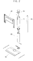
- FIG. 2 is an exploded perspective view of the stand of FIG. 1 ;
- FIG. 3A is an exploded perspective view of a base 100 of the stand of FIG. 1 ;
- FIG. 3B is an exploded perspective view of a supporting case 200 of the stand of FIG. 1 ;
- FIG. 3C is an exploded perspective view of an rotating case 300 of the stand according to a second embodiment of the present invention.
- FIG. 3D is an exploded perspective view of a supporting member 400 of the stand of FIG. 1 ;
- FIG. 3E is an exploded perspective view of an mounting bracket 500 of the stand of FIG. 1 ;
- FIG. 3F is an exploded perspective view of a cylinder part 600 of the display according to fourth fifth, and sixth embodiments of the present invention.
- FIG. 3G is an exploded perspective view of a display-mounting part 700 of the stand according to a third embodiment of the present invention.
- FIG. 4 is a sectional view showing a combination of the supporting case 200 and the rotating case 300 of the stand according to the second embodiment of the present invention.
- a first embodiment of the stand includes a base 100 , a supporting case 200 , a supporting member 400 that can be swiveled, and an mounting bracket 500 .
- a second embodiment of the stand includes a rotating case 300 in addition to the components of the first embodiment of the stand described above.
- the stand includes a display-mounting part 700 in addition to the components of the second embodiment of the stand. The display-mounting part 700 mounts on the mounting bracket 500 .
- FIG. 3A is an exploded perspective view of the base 100 of the stand according to the first embodiment of the present invention.
- the base 100 includes a base plate 110 , a seating part 120 , and an engaging hole 130 .
- An extending part 111 is located on a first end of the base plate 110 to widen a contact area of the base 100 , and thereby enhance stability.
- first and second sides of the base plate 110 are covered by a first cover 113 and a second cover 115 respectively.
- the seating part 120 located at a predetermined position on the base plate 110 corresponds in shape to the supporting case 200 .
- the seating part 120 there are a plurality of engaging holes 130 for seating the supporting case 200 .
- the supporting case 200 has a supporting trunk part 210 and a supporting guide 220 .
- the supporting trunk part 210 may be circular or polygonal.
- the rotating case 300 rotates, and thus the supporting trunk part 210 of the supporting case 200 corresponding thereto is approximately cylindrical.
- the supporting trunk part 210 has a penetrating pipe 211 through which the supporting member 400 passes.
- the supporting trunk part 210 additionally has a recess 213 accommodating a stopper 313 (see FIG. 3C ) to limit rotation of the display.
- the supporting guide 220 corresponds to the supporting trunk part 210 , and has an opening through which the supporting member 400 passes.
- the supporting guide 220 guides the supporting member 400 to pass therethrough, and transfers the weight of the display from the supporting member 400 to the supporting case 200 .
- the supporting guide 220 has a bending part 221 extending from a guiding flange with an opening that corresponds to the opening formed in the supporting guide 220 .
- the supporting case 200 has a supporting bracket 230 , a first bracket cover 240 , and a second bracket cover 250 .
- the supporting bracket 230 facilitates mounting the supporting case 200 on the base 100 , and has: a seating flange 231 , in which the supporting member 400 is seated; a first engaging hole 233 , engaging the supporting bracket 230 with the supporting trunk part 210 ; and a second engaging hole 235 , engaging the supporting bracket 230 with the seating part 120 of the base 100 .
- the supporting bracket 230 engages the lower end of the supporting trunk part 210 of the supporting case 200 through the first engaging hole 233 .
- the supporting case 200 engages the base 100 through the second engaging holes 235 after the supporting bracket 230 is inserted into the seating part 120 of the base 100 . Since a diameter of the supporting bracket 230 is larger than an external diameter of the supporting trunk part 210 , a portion of the supporting bracket 230 is exposed. The exposed portion is covered by the first and second bracket covers 240 and 250 .
- a trunk part 310 of the rotating case 300 has a hollow opening through which the supporting member 400 passes.
- the trunk part 310 is installed onto an upper part of the supporting case 200 . Since the trunk part 310 rotates when installed on an upper part of the supporting case 200 , according to one aspect, the trunk part 310 is approximately cylindrical.
- a projection part 320 protrudes from an inner surface of the trunk part 310 , and maintains a predetermined separation from an outer face of the supporting case 200 .
- a bracket-inserting opening 330 is an opening located on the first end of the trunk part 310 , and through which the rotating case 300 engages the mounting bracket 500 .
- the rotating case 300 additionally has an inserting guide 340 .
- the external diameter of the inserting guide 340 corresponds to an internal diameter of the trunk part 310
- the internal diameter of the inserting guide 340 corresponds to an external diameter of the supporting trunk part 210 .
- the lower part of the trunk part 310 is inserted onto the upper part of the supporting trunk part 210 .
- the trunk part 310 additionally has a wire holder 311 .
- the wire holder 311 is a protrusion that holds a plurality of wires connected to the display.
- the trunk part 310 additionally has a stopper 313 .
- the stopper 313 projects farther from an inner face of the trunk part 310 , than the projection part 320 .
- the stopper 313 is molded from an elastic material.
- the trunk part 310 is spaced from the supporting trunk part 210 to absorb an impact and facilitate a molding operation.
- a supporting member 400 has a supporting shaft 410 and a bracket-engaging part 420 .
- the bracket-engaging part 420 on a first end of the supporting shaft 410 engages an engaging part 510 of the mounting bracket 500 see FIG. 3E ).
- the bracket engaging part 420 and the engaging part 510 have corresponding shapes.
- the bracket engaging part 420 is polygonal and the engaging part 510 has a corresponding polygonal recess. It will be appreciated that the engaging part 510 may be polygonal, and the bracket engaging part 420 may have a corresponding polygonal recess.
- mounting bracket 500 has an engaging part 510 , a mounting face 520 , and a mounted hole 530 .
- engaging part 510 engages the bracket-engaging part 420 located on the first end of the supporting shaft 410 of the supporting member 400 .
- the mounting face 520 is shaped like a plate, with a face having the mounted hole 530 on which the display is mounted.
- the mounting bracket 500 additionally has a cover 540 and an inserting part 550 .
- the cover 540 covers a first end of the mounting bracket 500 to conceal the inside thereof.
- the inserting part 550 is needed in the second embodiment described above.
- the inserting part 550 is a boss of predetermined thickness that corresponds to the bracket-inserting opening 330 of the rotating case 300 .
- the boss is positioned between the engaging part 510 and the mounting face 520 , and extends away from the first end of the mounting bracket 500 .
- the inserting part 550 is inserted into the bracket-inserting opening 330 .
- cylinder part 600 has a cylinder cover 610 , a cylinder 620 and a bracket-engaging part 630 .
- cylinder 620 is a hydraulic cylinder filled with gas, such as air, and functions as a damping pot for translational movement of the cylinder part 600 .
- the bracket-engaging part 630 is polygonal. According to an aspect of the fifth and sixth embodiments, however, wherein the rotating case 300 rotates, the bracket-engaging part 630 is approximately cylindrical.
- the display-mounting part 700 has a display base plate 710 , a first engaging hole 720 , a first engaging part 730 , a second engaging part 740 , and a second engaging hole 750 .
- the display base plate 710 is shaped like a plate, and engages the mounting face 520 of the mounting bracket 500 through the first engaging hole 720 on the base plate 710 and the corresponding mounted hole 530 .
- the first engaging part 730 and the second engaging part 740 are planar shaped wings located on opposite sides of the base plate 710 , having the second engaging hole 750 , through which the display is mounted to the display mounting part 700 .
- the supporting case 200 is inserted into the rotating case 300 .
- the rotating case 300 maintains a predetermined separation from the inserted supporting case 200 , owing to the projection part 320 of the trunk part 310 . This separation and the projection part facilitate smooth rotation of the rotating case 300 .
- the predetermined angle through which the rotating case 300 rotates, is limited by the stopper 313 and the recess 213 of the supporting trunk part 210 .
- stopper 313 could be located on the external surface of the supporting case 200 , and the corresponding recess 213 could be located on the interior surface of the upper case 300 .
- the penetrating pipe 211 through which the cylinder part 600 passes, is located inside the supporting trunk part 210 .
- the stand is capable of swiveling and changing the distance between the base and the display, while supporting the weight of a large-sized display, and needing no separate device for swiveling and changing the elevation of the display.
- a display is mounted to the display mounting part 700 using the second engaging hole 750 .
- the display can be rotated by supplying a force of predetermined magnitude to a side of the display. Since the display mounting part 700 engages the mounting bracket 500 , which in turn engages the cylinder part 600 and the rotating case 300 , the force applied to the side of the display is transferred to the rotating case 300 , and results in rotation about the axis of the cylinder part 600 . This rotation continues until the stopper 313 encounters a side of the recess 213 (see FIG. 4 ). Similarly, rotation of the display can occur in the opposite direction until the stopper 313 encounters an opposing side of the recess 213 .
- the elevation of the display can be changed by applying a force of predetermined magnitude to a top or a bottom of the display.
- the force is applied to the top of the display.
- the force is transferred from the display to the display mounting part 700 , and in turn to the mounting bracket 500 and the cylinder part 600 , as described previously.
- the force compresses the cylinder part 600 , sliding the cylinder 620 into the cylinder cover 610 , and changing the elevation.
Abstract
Description
Claims (44)
Applications Claiming Priority (2)
| Application Number | Priority Date | Filing Date | Title |
|---|---|---|---|
| KR1020020066642A KR100770981B1 (en) | 2002-10-30 | 2002-10-30 | Stand of Display |
| KR2002-0066642 | 2002-10-30 |
Publications (2)
| Publication Number | Publication Date |
|---|---|
| US20040084579A1 US20040084579A1 (en) | 2004-05-06 |
| US7195214B2 true US7195214B2 (en) | 2007-03-27 |
Family
ID=32171559
Family Applications (1)
| Application Number | Title | Priority Date | Filing Date |
|---|---|---|---|
| US10/694,041 Expired - Fee Related US7195214B2 (en) | 2002-10-30 | 2003-10-28 | Stand for display |
Country Status (3)
| Country | Link |
|---|---|
| US (1) | US7195214B2 (en) |
| KR (1) | KR100770981B1 (en) |
| CN (1) | CN100583302C (en) |
Cited By (53)
| Publication number | Priority date | Publication date | Assignee | Title |
|---|---|---|---|---|
| US20040035994A1 (en) * | 2002-08-24 | 2004-02-26 | Samsung Electronics Co., Ltd | Display apparatus |
| US20040118984A1 (en) * | 2002-09-27 | 2004-06-24 | Samsung Electronics Co., Ltd. | Display apparatus |
| US20040231213A1 (en) * | 2003-05-23 | 2004-11-25 | Samsung Electronic Co., Ltd. | Display apparatus |
| US20050006537A1 (en) * | 2001-11-19 | 2005-01-13 | Samsung Electronics Co., Ltd. | Monitor improved in a tilting and combining structure |
| US20050050784A1 (en) * | 2003-09-04 | 2005-03-10 | Won-Kyu Bang | Display device and support stand therefor |
| US20050284991A1 (en) * | 2004-06-10 | 2005-12-29 | Humanscale Corporation | Mechanism for positional adjustment of an attached device |
| US20060290832A1 (en) * | 2005-06-23 | 2006-12-28 | Yu-Chuan Lin | Display and electronic apparatus |
| US20060289704A1 (en) * | 2005-06-28 | 2006-12-28 | Siemens Medical Solutions Usa, Inc. | Adjustable support mechanism for a flat-panel display |
| US20070034756A1 (en) * | 2005-08-10 | 2007-02-15 | Jiinming Industry Co., Ltd. | Retractable support tube structure |
| US20070047188A1 (en) * | 2005-08-23 | 2007-03-01 | Samsung Electronics Co., Ltd. | Display apparatus |
| US20070215762A1 (en) * | 2005-09-13 | 2007-09-20 | Kyung-Kyun Lee | Display apparatus having a swiveling structure |
| US20070215776A1 (en) * | 2006-03-16 | 2007-09-20 | Benq Corporation | Display panel and elevation adjusting base of the same |
| US20070215760A1 (en) * | 2006-01-23 | 2007-09-20 | Funai Electric Co., Ltd. | Display support mechanism |
| US20070284488A1 (en) * | 2002-11-11 | 2007-12-13 | Samsung Electronics Co., Ltd. | Monitor |
| US20070295020A1 (en) * | 2006-06-21 | 2007-12-27 | Lee Sung-Ae | Display assembly for refrigerator |
| US20080173774A1 (en) * | 2007-01-24 | 2008-07-24 | Manuel Saez | Accessory Holder |
| US20080239643A1 (en) * | 2007-03-27 | 2008-10-02 | Min Kyung-Hwan | Display device |
| US20090073643A1 (en) * | 2007-09-07 | 2009-03-19 | Asustek Computer Inc. | Display device and rotatable stand thereof |
| US20090173845A1 (en) * | 2008-01-09 | 2009-07-09 | Hong Fu Jin Precision Industry (Shenzhen) Co., Ltd. | Elevating mechanism for flat-panel display monitor and pneumatic cylinder used for elevating mechanism |
| US20090173847A1 (en) * | 2007-01-24 | 2009-07-09 | Wolfgang Dittmer | Accessory Holder |
| US20100103596A1 (en) * | 2008-10-24 | 2010-04-29 | Hong Fu Jin Precision Industry (Shenzhen) Co., Ltd | Rotation module and electronic device using the same |
| US7738245B1 (en) * | 2009-11-23 | 2010-06-15 | Peerless Industries, Inc. | Display mount |
| US20100231815A1 (en) * | 2009-03-12 | 2010-09-16 | Samsung Electronics Co., Ltd. | Supporting device for display unit and display unit having the same |
| US20110079692A1 (en) * | 2009-10-07 | 2011-04-07 | Chin-Chu Li | Support frame with an adjustable mechanism |
| US20110101179A1 (en) * | 2009-06-29 | 2011-05-05 | Fritch Brian D | Tv support structure with latching mechanism |
| US20110141674A1 (en) * | 2004-10-25 | 2011-06-16 | Samsung Electronics Co., Ltd | Display device |
| US20110149510A1 (en) * | 2009-12-23 | 2011-06-23 | Humanscale Corporation | Adjustable Laptop Holder |
| US20110147546A1 (en) * | 2009-12-23 | 2011-06-23 | Humanscale Corporation | Adjustable Display Arm |
| US20120224303A1 (en) * | 2011-03-02 | 2012-09-06 | Kunshan Eson Precision Engineering Co., Ltd. | Support and display device using the same |
| US20130094127A1 (en) * | 2011-10-18 | 2013-04-18 | Shixiong Lu | Monitor fixing mechanism for fixing a monitor and display device therewith |
| US8469323B1 (en) * | 2008-04-21 | 2013-06-25 | Yani Deros | Modular monitor support assembly |
| US20150014493A1 (en) * | 2013-07-09 | 2015-01-15 | Dongguan Cheng Jie Electronics Co., Ltd. | Display Elevating Device |
| US8937395B2 (en) * | 2012-08-08 | 2015-01-20 | Atargis Energy Corporation | Ocean floor mounting of wave energy converters |
| US20150146389A1 (en) * | 2012-05-18 | 2015-05-28 | Sharp Kabushiki Kaisha | Display device and television receiver |
| US9298213B2 (en) | 2013-02-25 | 2016-03-29 | Dell Products Lp | Transforming modular display systems and methods of using same |
| CN105957453A (en) * | 2016-05-25 | 2016-09-21 | 广西东显电子有限公司 | Rotary type LED display screen |
| USD773465S1 (en) | 2013-08-22 | 2016-12-06 | Palmer Distributors, Incorporated | Docking station for an electronic device |
| US9657889B1 (en) | 2013-03-15 | 2017-05-23 | Humanscale Corporation | Adjustable support arm |
| USD853403S1 (en) * | 2019-01-31 | 2019-07-09 | Yaqi Lyu | Support for television apparatus |
| USD877743S1 (en) * | 2018-12-13 | 2020-03-10 | Xubo Pei | TV mount bracket |
| USD877745S1 (en) * | 2018-12-07 | 2020-03-10 | CKnapp Sales, Inc. | Adjustable monitor stand |
| US10851938B2 (en) | 2018-04-02 | 2020-12-01 | Humanscale Corporation | Adjustable support arm |
| USD912024S1 (en) * | 2019-11-01 | 2021-03-02 | Xinadda (Hong Kong) Limited | TV mount bracket |
| USD914658S1 (en) * | 2019-11-30 | 2021-03-30 | Xu Bo Pei | Mobile stand for display device |
| USD919630S1 (en) * | 2020-04-09 | 2021-05-18 | Yaqi Lyu | Monitor stand |
| USD920987S1 (en) * | 2019-08-20 | 2021-06-01 | Yaqi Lyu | Monitor stand |
| USD921621S1 (en) * | 2020-11-12 | 2021-06-08 | Shenzhen Bestqi Innovation Technology Co., Ltd | Display mount |
| USD928129S1 (en) * | 2020-08-27 | 2021-08-17 | Ningbo Qi'an Household Technology Co., Ltd. | Display mount |
| USD928128S1 (en) * | 2020-08-27 | 2021-08-17 | Perle Electronics Hardware (Hongkong) Co., Limited | Display mount |
| US11131420B2 (en) | 2017-06-26 | 2021-09-28 | Hewlett-Packard Development Company, L.P. | Display arm to housing connectors |
| USD944813S1 (en) * | 2020-11-17 | 2022-03-01 | Shenzhen Bestqi Innovation Technology Co., Ltd | Display mount |
| USD947857S1 (en) * | 2019-10-18 | 2022-04-05 | Yaqi Lyu | Monitor stand |
| USD958122S1 (en) * | 2018-09-14 | 2022-07-19 | Shenzhen Vgoode Technologies Co., Ltd. | Display cart |
Families Citing this family (41)
| Publication number | Priority date | Publication date | Assignee | Title |
|---|---|---|---|---|
| AUPS285202A0 (en) * | 2002-06-07 | 2002-06-27 | Claiteal Pty Ltd | Stand for flat panel display |
| TWI228372B (en) * | 2003-10-30 | 2005-02-21 | Quanta Comp Inc | Plastic adjustable pedestal |
| US7088577B2 (en) * | 2004-03-25 | 2006-08-08 | Dell Products L.P. | System and method for managing information handling system adjustable cables |
| KR20060007712A (en) * | 2004-07-21 | 2006-01-26 | 삼성에스디아이 주식회사 | Image display device having slim type cathode ray tube |
| CN100381030C (en) * | 2004-10-22 | 2008-04-09 | 南京Lg同创彩色显示系统有限责任公司 | Rotary structure of image display machine |
| CN100373087C (en) * | 2004-11-04 | 2008-03-05 | 南京Lg同创彩色显示系统有限责任公司 | Horizontal rotating device for image display |
| CN100342298C (en) * | 2005-01-25 | 2007-10-10 | 名达亚洲有限公司 | Supporter of computer planar displaying device with three-dimensional regulating |
| KR100684997B1 (en) * | 2005-03-08 | 2007-02-20 | 삼성전자주식회사 | Monitor apparatus |
| US11311106B2 (en) | 2005-05-24 | 2022-04-26 | Whalen Llc | Television support and mounting kit |
| US8561551B2 (en) | 2005-05-24 | 2013-10-22 | Whalen Furniture Manufacturing, Inc. | Television support and mounting kit |
| US7530538B2 (en) * | 2005-05-24 | 2009-05-12 | Whalen Furniture Manufacturing, Inc. | Flat screen television support system |
| US8079311B2 (en) | 2007-08-08 | 2011-12-20 | Whalen Furniture Manufacturing, Inc. | Television support and mounting kit |
| TWI267300B (en) * | 2005-08-25 | 2006-11-21 | Techview Internat Technology I | Display module |
| US20070057133A1 (en) * | 2005-09-14 | 2007-03-15 | Cottingham Paul H | Method, device and/or kit for mounting a flat or planar panel display |
| US7513469B1 (en) | 2006-01-05 | 2009-04-07 | Peerless Industries, Inc. | Mounting system with vertical adjustment feature |
| US7487943B1 (en) | 2006-01-05 | 2009-02-10 | Peerless Industries, Inc. | Dual arm mounting system with vertical adjustment feature |
| WO2007086025A1 (en) * | 2006-01-27 | 2007-08-02 | Koninklijke Philips Electronics N.V. | Stand and screen holder for use on such a stand |
| CN101047041B (en) * | 2006-03-31 | 2010-06-16 | 明基电通股份有限公司 | Display and lifting base thereof |
| KR100825918B1 (en) * | 2006-09-12 | 2008-04-29 | 주식회사 우성엔터프라이즈 | A stand for flat-plate type tv monitor |
| TWI348047B (en) * | 2006-11-14 | 2011-09-01 | Hannspree Inc | Display device |
| CN101364449B (en) * | 2007-08-10 | 2010-09-29 | 友达光电股份有限公司 | Planar display having integrated molded support structure |
| JP2009047892A (en) * | 2007-08-20 | 2009-03-05 | Berutekku Kk | Supporting stand of flat display device |
| CN101555977B (en) * | 2008-04-11 | 2011-06-22 | 鸿富锦精密工业(深圳)有限公司 | Support device |
| CN101943311B (en) * | 2010-08-23 | 2012-12-26 | 广东爵仕泳池水疗设备有限公司 | Multifunctional TV mount |
| WO2012106552A2 (en) * | 2011-02-02 | 2012-08-09 | Carr James E | Universal television lift with enclosure |
| CN102809033B (en) * | 2011-05-30 | 2015-06-24 | 鸿富锦精密工业(深圳)有限公司 | Supporting device |
| US8985534B1 (en) | 2012-08-08 | 2015-03-24 | Lf Centennial Limited | Multi-configurable TV stand with bridging mount structure |
| US8813656B1 (en) | 2012-08-08 | 2014-08-26 | LF Centennial Limted | Multi-configurable TV stand with top surface joined vertical structure |
| KR102091540B1 (en) * | 2012-09-28 | 2020-03-20 | 삼성전자주식회사 | Display Device and Terminal Having the Same |
| JP2014082557A (en) * | 2012-10-12 | 2014-05-08 | Toshiba Corp | Television receiver and electronic apparatus |
| CN103423553A (en) * | 2013-07-26 | 2013-12-04 | 昆山维金五金制品有限公司 | Display screen base fixing device |
| CN103438335A (en) * | 2013-08-29 | 2013-12-11 | 昆山建金工业设计有限公司 | Displayer base with storage function |
| USD737081S1 (en) | 2014-10-24 | 2015-08-25 | Apple Inc. | Display stand |
| CN105003535A (en) * | 2015-07-03 | 2015-10-28 | 苏州利宏原精密零件有限公司 | Chute structure |
| USD787522S1 (en) * | 2015-12-23 | 2017-05-23 | Samsung Electronics Co., Ltd | Stand for monitor |
| USD837223S1 (en) * | 2017-10-19 | 2019-01-01 | Dell Products L.P. | Display stand |
| CN108006378A (en) * | 2017-11-28 | 2018-05-08 | 苏州佳世达电通有限公司 | A kind of general purpose display support device |
| USD894196S1 (en) * | 2019-05-30 | 2020-08-25 | Dell Products L.P. | Display stand |
| USD893926S1 (en) | 2019-06-21 | 2020-08-25 | Apple Inc. | Product retainer |
| TWD201608S (en) * | 2019-07-14 | 2019-12-21 | 信錦企業股份有限公司 | Supporting frame |
| USD928172S1 (en) * | 2020-06-25 | 2021-08-17 | Dell Products L.P. | Display stand |
Citations (115)
| Publication number | Priority date | Publication date | Assignee | Title |
|---|---|---|---|---|
| US2041370A (en) * | 1935-12-04 | 1936-05-19 | Pottorff Victor Vear | Display stand |
| US2628142A (en) * | 1950-02-03 | 1953-02-10 | Dubach Lena Emma | Telescoping support for a tray having a tiltable head |
| US2890010A (en) | 1954-12-16 | 1959-06-09 | Donald I Barkheimer | Adjustable television receiver stand |
| US3788587A (en) | 1971-12-23 | 1974-01-29 | Stabilus Ind Handels Gmbh | Resilient column |
| US4113215A (en) | 1976-01-17 | 1978-09-12 | W. Vinten Limited | Tilt mounting heads |
| US4166522A (en) | 1976-04-30 | 1979-09-04 | Bourcier Carbon Christian | Pneumatic spring device |
| US4235405A (en) | 1979-03-23 | 1980-11-25 | ENG Helicopter Satellites, Ltd. | Support apparatus for a camera |
| US4329800A (en) * | 1980-12-02 | 1982-05-18 | Eastern Electrical Equipment Co., Inc. | Adjustable display device |
| US4339104A (en) * | 1980-04-23 | 1982-07-13 | Weidman Marilyn V | Floor stand mounted mirror |
| US4395010A (en) * | 1980-09-30 | 1983-07-26 | Tandberg Data A/S | Device for the setting up of a data display device on a work surface |
| US4438458A (en) | 1981-02-16 | 1984-03-20 | Siemens Aktiengesellschaft | Data display device |
| US4447031A (en) | 1981-04-13 | 1984-05-08 | Positioning Devices, Inc. | Spring counterbalanced support arm system |
| US4601246A (en) | 1984-05-07 | 1986-07-22 | Thill, Inc. | Support assembly for overbed table |
| US4669694A (en) | 1985-12-23 | 1987-06-02 | American Telephone And Telegraph Company, At&T Bell Laboratories | Tilt adjusting mechanism |
| US4690362A (en) * | 1984-06-26 | 1987-09-01 | Tangberg Data A/S | Adjustable stand for a visual display unit |
| US4691886A (en) | 1985-04-18 | 1987-09-08 | Texas Instruments Incorporated | Adjustable display stand |
| US4729533A (en) | 1986-04-19 | 1988-03-08 | International Business Machines Corporation | Support apparatus |
| USD295415S (en) | 1985-11-15 | 1988-04-26 | American Telephone And Telegraph Company, At&T Bell Laboratories | Adjustable support for plasma display panel |
| US4768744A (en) | 1986-08-27 | 1988-09-06 | Richard Leeds | Apparatus for supporting a load in a dynamically balanced condition |
| US4777750A (en) * | 1984-05-14 | 1988-10-18 | Clamp Swing Pricing Co. | Frame system |
| US4834329A (en) | 1987-05-29 | 1989-05-30 | Michael Delapp | Monitor support for a terminal |
| US4846434A (en) | 1988-08-04 | 1989-07-11 | Jac Jacobsen Industrier A.S. | Counterbalanced arm assembly |
| US4859092A (en) | 1986-11-18 | 1989-08-22 | Kabushiki Kaisha Toshiba | Portable apparatus with a mechanism for holding a display above a printer while the printer is printing data |
| US4864601A (en) | 1988-04-20 | 1989-09-05 | Berry Wayne F | Integrated voice data workstation |
| US4924931A (en) | 1985-11-25 | 1990-05-15 | Channel-Kor Systems Inc. | Panel device |
| USD313405S (en) | 1987-05-27 | 1991-01-01 | Barry Michael R | Computer display with adjustable stand |
| US4989813A (en) | 1989-11-29 | 1991-02-05 | Samsung Electron Devices Co., Ltd. | Supporting base for controlling height, swivel and inclination of display means |
| US5012852A (en) * | 1989-03-06 | 1991-05-07 | Blackhurst Michael L | Barrier assembly |
| US5088676A (en) | 1988-06-30 | 1992-02-18 | Ncr Corporation | Compact height adjustable base for a display |
| US5102084A (en) | 1989-10-16 | 1992-04-07 | Hyundai Electronics Ind. Co., Ltd. | Positioning apparatus with gears and a pivot for angularly and longitudinally positioning the screen of a lap top computer |
| US5107402A (en) | 1989-01-05 | 1992-04-21 | Telemecanique | Portable computer provided with a tilting screen articulated thereon by tilting linkage with a bent shape |
| US5112019A (en) | 1991-02-04 | 1992-05-12 | Storz Instrument Company | Motorized IV pole assembly |
| US5144290A (en) | 1988-10-31 | 1992-09-01 | Kabushiki Kaisha Toshiba | Display unit attachment device |
| US5163652A (en) * | 1991-09-30 | 1992-11-17 | King Paul F | Clamp and rod holder assembly |
| US5206790A (en) | 1991-07-11 | 1993-04-27 | Zeos International, Ltd. | Pivot and swivel mechanism for lap top display |
| USD337104S (en) | 1991-08-15 | 1993-07-06 | Ncr Corporation | Flat screen display terminal |
| US5335142A (en) | 1992-12-21 | 1994-08-02 | Ast Research, Inc. | Portable computer display tilt/swivel mechanism |
| USD349489S (en) | 1993-03-09 | 1994-08-09 | Wang Jing Y | LCD monitor |
| US5383138A (en) | 1992-07-13 | 1995-01-17 | Fujitsu Limited | Folding portable data processing apparatus with three hinge points |
| US5422951A (en) | 1985-04-26 | 1995-06-06 | Kabushiki Kaisha Toshiba | Low profile telephone set |
| US5437236A (en) | 1994-10-17 | 1995-08-01 | Zeiner; Harold R. | Multi-functional table with elevational capabilities |
| US5751548A (en) * | 1996-05-13 | 1998-05-12 | International Business Machines Corporation | Docking station for a portable computer providing rotational movement of the computer's viewable screen in three different planes |
| US5758849A (en) | 1996-12-20 | 1998-06-02 | Bui; Khan Duc | Assembly for supporting a computer and related equipment at a selected height |
| US5771152A (en) | 1995-05-08 | 1998-06-23 | International Business Machines Corporation | Computer system with a tilt adjustment mechanism |
| US5799917A (en) | 1996-12-17 | 1998-09-01 | Li; Chin-Chu | Adjustable supporting bracket |
| US5812368A (en) | 1997-06-04 | 1998-09-22 | Kuo Feng Corporation | Monitor viewing angle adjusting assembly having monitor mounted on two supporting arm assemblies via turning limit assemblies |
| US5835342A (en) | 1996-03-05 | 1998-11-10 | Hunte; Stanley G. | Computer desktop-keyboard cover with built-in monitor screen and wrist support accessory |
| US5876008A (en) | 1995-01-17 | 1999-03-02 | Ergotron, Inc. | Suspension system for video monitor or other equipment |
| US5911523A (en) * | 1997-07-22 | 1999-06-15 | Burchart; John Lewis | Adjustable display support |
| US5924665A (en) | 1996-06-07 | 1999-07-20 | Ergotron, Inc. | Ceiling system for a flat panel display |
| US5941493A (en) | 1996-11-16 | 1999-08-24 | Adi Corporation | LCD support system |
| US5975472A (en) | 1998-11-19 | 1999-11-02 | Hung; Chin-Jui | Video display support having angle adjustment |
| US5997493A (en) | 1996-09-25 | 1999-12-07 | Johnson & Johnsonprofessional, Inc. | "Hinge with movement limitation" |
| US6012693A (en) | 1998-02-19 | 2000-01-11 | Ergotron, Inc. | Multi-function display mounting system |
| US6018847A (en) | 1998-07-02 | 2000-02-01 | Lu; Sheng-Nan | Hinge axle device for a LCD monitor |
| US6031714A (en) | 1997-12-08 | 2000-02-29 | Ma; His Kuang | Portable flat display device |
| US6062148A (en) | 1997-08-01 | 2000-05-16 | Steelcase Development Inc. | Height adjustable support for computer equipment and the like |
| US6064373A (en) | 1993-06-29 | 2000-05-16 | Ditzik; Richard J. | Desktop computer with adjustable flat panel screen |
| US6081420A (en) | 1996-10-01 | 2000-06-27 | Samsung Electronics Co., Ltd. | LCD display apparatus |
| US6113046A (en) | 1999-08-26 | 2000-09-05 | Wang; James | Angle-adjustable, auto-locking apparatus support |
| US6116690A (en) | 1997-09-08 | 2000-09-12 | Larson; John E. | Height adjustable work chair having a non-swivel seat |
| US6134103A (en) | 1998-10-30 | 2000-10-17 | Ghanma; Tony | Flat panel display with adjustable height for a portable computer |
| US6164611A (en) | 1997-09-18 | 2000-12-26 | Gamber Johnson | Quad-motion device |
| US6168124B1 (en) | 1997-12-18 | 2001-01-02 | Sanyo Electric Co., Ltd. | Image receiving monitor using LCD |
| US6189849B1 (en) | 1998-05-06 | 2001-02-20 | Ergotron, Inc. | Lift system |
| US6189842B1 (en) * | 1999-06-21 | 2001-02-20 | Palo Alto Design Group | Tilt and swivel adjustment of flat panel display having detents for landscape and portrait positions and kickout for preventing contact between flat panel display and base |
| US6189850B1 (en) | 1997-08-09 | 2001-02-20 | Mitac International Corp. | Rotatable LCD screen device |
| US6233138B1 (en) | 1999-07-16 | 2001-05-15 | Evergreen Innovations, L.L.C. | Telescoping pivot hinge for computer display |
| US6270047B1 (en) | 1998-11-06 | 2001-08-07 | Compx International Inc. | Keyboard tilt mechanism |
| US6288891B1 (en) | 1996-11-21 | 2001-09-11 | Canon Kabushiki Kaisha | Movable display apparatus |
| US6286794B1 (en) | 1999-06-14 | 2001-09-11 | Bradley Harbin | Ergonomic computer mounting device permitting extensive vertical, horizontal and angular ranges of motion |
| US6305659B1 (en) * | 1999-02-07 | 2001-10-23 | Leica Microsystems Ag | Stand, in particular a microscope stand |
| US20020011544A1 (en) | 2000-03-30 | 2002-01-31 | Bosson Peter Thomas | Display device support system |
| US6347433B1 (en) | 1999-06-18 | 2002-02-19 | Cema Technologies, Inc. | Flat panel display tilt and swivel mechanism |
| US6352226B1 (en) | 1999-10-18 | 2002-03-05 | Rosen Products, Llc | Monitor lift apparatus |
| US6367756B1 (en) | 2000-07-07 | 2002-04-09 | James Wang | Adjustable device support and anchor means arrangement |
| US6381125B1 (en) * | 1999-07-29 | 2002-04-30 | Kabushiki Kaisha Toshiba | Personal computer |
| US6390433B1 (en) | 1991-05-22 | 2002-05-21 | Vladimir Kasa-Djukic | Easel, especially for canvas frames (stretchers), for use in painting |
| US6394403B1 (en) | 2000-10-26 | 2002-05-28 | Ray Hung | Supporting device for a liquid crystal display |
| US6397761B1 (en) * | 2000-06-02 | 2002-06-04 | Balt, Inc | Computer workstation |
| US6402109B1 (en) | 2001-05-16 | 2002-06-11 | Chief Manufacturing, Inc. | Self-balancing mounting system for a flat panel display |
| US6409134B1 (en) | 1999-06-07 | 2002-06-25 | Innovative Office Products, Inc. | Arm apparatus for mounting electronic devices with cable management system |
| US6430038B1 (en) | 2000-04-18 | 2002-08-06 | Hewlett-Packard Company | Computer with articulated mechanism |
| US20020130981A1 (en) | 2001-03-19 | 2002-09-19 | Compal Electronics, Inc. | Monitor assembly with an inclination-adjustable monitor unit |
| US6478275B1 (en) | 2001-08-31 | 2002-11-12 | Min Hwa Huang | Support device for monitor, displayer or other object |
| US6494150B1 (en) | 2001-03-02 | 2002-12-17 | Precision Lifts Of Deerfield Beach, Incorporated | Elevating apparatus for visual displays |
| US6499704B2 (en) * | 1999-06-02 | 2002-12-31 | Innovative Office Products, Inc. | Polestand apparatus for mounting electronic devices |
| US6502792B1 (en) | 1999-10-26 | 2003-01-07 | Samsung Electronics Co., Ltd. | LCD monitor stand having a multistage structure |
| US6522530B2 (en) | 2000-08-04 | 2003-02-18 | Samsung Electronics Co., Ltd. | Computer system having a monitor movably coupled to a main body |
| US20030075649A1 (en) * | 2001-10-24 | 2003-04-24 | Samsung Electronics Co., Ltd. | LCD monitor stand |
| US20030075653A1 (en) | 2001-10-19 | 2003-04-24 | Chin-Chu Li | Liquid crystal display support |
| US20030086240A1 (en) | 2001-11-08 | 2003-05-08 | Jobs Steven P | Computer controlled display device |
| US6585201B1 (en) * | 2002-03-08 | 2003-07-01 | Gregory Reed | Detachable universal display mount |
| US6592090B1 (en) | 2002-08-23 | 2003-07-15 | Chin-Chu Li | Object supporting structure |
| US20030132360A1 (en) | 2002-01-11 | 2003-07-17 | Ju Li Ta | Structure of an adjustable LCD screen |
| US20030142474A1 (en) | 2002-01-28 | 2003-07-31 | International Business Machines Corporation | Personal computer device having constant tilt display with adjustable height |
| US6609686B2 (en) | 2002-01-18 | 2003-08-26 | Tam Srl | Adjustable support apparatus |
| US6672533B1 (en) | 1999-08-18 | 2004-01-06 | Saab Ab | Method and guidance system for guiding a missile |
| US6680843B2 (en) | 2001-09-28 | 2004-01-20 | International Business Machines Corporation | All-in-one personal computer with tool-less quick-release features for various elements thereof including a reusable thin film transistor monitor |
| US20040011932A1 (en) | 2002-06-07 | 2004-01-22 | Simon Duff | Stand for flat panel display |
| US6695266B1 (en) | 2003-05-05 | 2004-02-24 | Chih-Cheng Tsai | Internal telescopic stand for inanimate objects |
| US6695274B1 (en) | 2002-08-01 | 2004-02-24 | Posen Chiu | Mounting device for a display |
| US6702238B1 (en) * | 2003-03-28 | 2004-03-09 | Top Victory Electronics Co., Ltd. | Adjustable supporting device for a display panel |
| US6708940B2 (en) | 2000-06-13 | 2004-03-23 | Peter Ligertwood | Mounting bracket |
| US20040056161A1 (en) | 2001-12-13 | 2004-03-25 | Takashi Ishizaki | Elevation regulator of display |
| US20040057197A1 (en) | 2002-09-24 | 2004-03-25 | International Business Machines Corporation | User friendly computer equipment, monitor unit, and monitor unit setting base |
| US6712321B1 (en) | 2003-05-21 | 2004-03-30 | Compal Electronics, Inc. | Adjustable supporting device for a display panel |
| USD489370S1 (en) | 2001-11-08 | 2004-05-04 | Apple Computer, Inc. | Display device with a moveable assembly |
| US20040084585A1 (en) | 2001-12-13 | 2004-05-06 | Atsushi Watanabe | Direction regulator of display |
| US6766994B2 (en) | 2002-04-05 | 2004-07-27 | 3M Innovative Properties Company | Stabilized flat panel touch monitor |
| US6769657B1 (en) | 2003-04-09 | 2004-08-03 | Min Hwa Huang | Support device for monitor, display or objects |
| US6822857B2 (en) * | 2002-07-16 | 2004-11-23 | Samsung Electronics Co., Ltd. | Monitor improved in a tilting structure |
| US6837469B2 (en) | 2003-05-01 | 2005-01-04 | Wei Chung Wu | Structure of liquid crystal display (LCD) |
| US6857610B1 (en) * | 2001-12-10 | 2005-02-22 | John P. Conner | Position adjustable load support mechanism |
| US6889958B2 (en) * | 2000-07-28 | 2005-05-10 | Donald A. Hoffend, Jr. | Brake for hoist assembly |
Family Cites Families (31)
| Publication number | Priority date | Publication date | Assignee | Title |
|---|---|---|---|---|
| US433073A (en) * | 1890-07-29 | Dumping-car | ||
| US258783A (en) * | 1882-05-30 | Reversible chuck-jaw | ||
| US64778A (en) * | 1867-05-14 | Improved beick machine | ||
| US536423A (en) * | 1895-03-26 | Erick a | ||
| US32381A (en) * | 1861-05-21 | Bolt and rivet machine | ||
| US4083555A (en) * | 1977-04-11 | 1978-04-11 | Pitney-Bowes, Inc. | Sheet-material separator and feeder system |
| US4155440A (en) * | 1977-07-05 | 1979-05-22 | Pitney-Bowes, Inc. | Document turning station |
| US4257587A (en) * | 1978-10-30 | 1981-03-24 | Xerox Corporation | Document registering and feeding apparatus |
| US5012915A (en) * | 1990-02-15 | 1991-05-07 | H.G. Weber & Co., Inc. | Method and apparatus for rotating an item |
| US5109975A (en) * | 1990-02-15 | 1992-05-05 | H.G. Weber & Co., Inc | Segmented turning device |
| DE4112094A1 (en) * | 1991-04-12 | 1992-10-22 | Basf Magnetics Gmbh | METHOD FOR PRODUCING A MAGNETIC RECORDING CARRIER |
| US6199874B1 (en) * | 1993-05-26 | 2001-03-13 | Cornell Research Foundation Inc. | Microelectromechanical accelerometer for automotive applications |
| FR2710626B1 (en) * | 1993-09-27 | 1995-11-10 | Cga Hbs | Device for transferring flat objects and unstacking device equipped with this transfer device. |
| SE503120C2 (en) * | 1995-03-31 | 1996-03-25 | Inter Innovation Ab | Device for correct feeding of thin objects, such as banknotes, checks, etc. |
| JPH09196048A (en) * | 1996-01-18 | 1997-07-29 | Kato Electrical Mach Co Ltd | Tilt hinge |
| US6059284A (en) * | 1997-01-21 | 2000-05-09 | Xerox Corporation | Process, lateral and skew sheet positioning apparatus and method |
| KR19990024492U (en) * | 1997-12-12 | 1999-07-05 | 윤종용 | Flat panel display device with hinged device for tilt operation |
| KR19990030749U (en) * | 1997-12-30 | 1999-07-26 | 김영환 | LCD Monitor Control |
| FR2781400B1 (en) * | 1998-07-27 | 2000-09-29 | Genus Technologies | CENTERING AND CLAMPING DEVICE, PARTICULARLY FOR PARTS OF AUTOMOTIVE BODYWORK |
| KR20000073609A (en) * | 1999-05-12 | 2000-12-05 | 윤종용 | LCD Monitor Capable Of Controlling Height Thereof |
| US6182815B1 (en) * | 1999-05-24 | 2001-02-06 | Dorner Mfg. Corp. | Inductor station for sortation conveying system |
| US6328300B1 (en) * | 1999-10-04 | 2001-12-11 | Pitney Bowes Inc. | Aligner mechanism for a mail handling system |
| US6338483B1 (en) * | 1999-11-23 | 2002-01-15 | Jeffrey L. Andela | Single sheet feeder with selectively engageable prefeeding rolls |
| KR100364732B1 (en) * | 2000-07-08 | 2002-12-16 | 엘지전자 주식회사 | Hinge assembly in LCD monitor |
| KR20020012988A (en) * | 2000-08-10 | 2002-02-20 | 구자홍 | Apparatus for adjusting screen position for monitor |
| US6378830B1 (en) * | 2000-10-05 | 2002-04-30 | Lu Sheng-Nan | Adjustable support for an LCD monitor |
| KR200250276Y1 (en) * | 2001-07-10 | 2001-11-17 | 주식회사 와이드 | Standing device of a monitor possible for automatic lifting and falling and rotation |
| KR100463524B1 (en) * | 2002-05-29 | 2004-12-29 | 엘지전자 주식회사 | Hinge assembly for video display appliance |
| TW543017B (en) * | 2002-09-20 | 2003-07-21 | Benq Corp | Monitor with changeable stand |
| KR100476090B1 (en) * | 2002-09-27 | 2005-03-11 | 삼성전자주식회사 | Monitor |
| US7055218B2 (en) * | 2004-06-01 | 2006-06-06 | Shin Zu Shing Co., Ltd. | Hinge |
-
2002
- 2002-10-30 KR KR1020020066642A patent/KR100770981B1/en not_active IP Right Cessation
-
2003
- 2003-10-24 CN CN200310102583A patent/CN100583302C/en not_active Expired - Fee Related
- 2003-10-28 US US10/694,041 patent/US7195214B2/en not_active Expired - Fee Related
Patent Citations (121)
| Publication number | Priority date | Publication date | Assignee | Title |
|---|---|---|---|---|
| US2041370A (en) * | 1935-12-04 | 1936-05-19 | Pottorff Victor Vear | Display stand |
| US2628142A (en) * | 1950-02-03 | 1953-02-10 | Dubach Lena Emma | Telescoping support for a tray having a tiltable head |
| US2890010A (en) | 1954-12-16 | 1959-06-09 | Donald I Barkheimer | Adjustable television receiver stand |
| US3788587A (en) | 1971-12-23 | 1974-01-29 | Stabilus Ind Handels Gmbh | Resilient column |
| US4113215A (en) | 1976-01-17 | 1978-09-12 | W. Vinten Limited | Tilt mounting heads |
| US4166522A (en) | 1976-04-30 | 1979-09-04 | Bourcier Carbon Christian | Pneumatic spring device |
| US4235405A (en) | 1979-03-23 | 1980-11-25 | ENG Helicopter Satellites, Ltd. | Support apparatus for a camera |
| US4339104A (en) * | 1980-04-23 | 1982-07-13 | Weidman Marilyn V | Floor stand mounted mirror |
| US4395010A (en) * | 1980-09-30 | 1983-07-26 | Tandberg Data A/S | Device for the setting up of a data display device on a work surface |
| US4329800A (en) * | 1980-12-02 | 1982-05-18 | Eastern Electrical Equipment Co., Inc. | Adjustable display device |
| US4438458A (en) | 1981-02-16 | 1984-03-20 | Siemens Aktiengesellschaft | Data display device |
| US4447031A (en) | 1981-04-13 | 1984-05-08 | Positioning Devices, Inc. | Spring counterbalanced support arm system |
| US4601246A (en) | 1984-05-07 | 1986-07-22 | Thill, Inc. | Support assembly for overbed table |
| US4777750A (en) * | 1984-05-14 | 1988-10-18 | Clamp Swing Pricing Co. | Frame system |
| US4690362A (en) * | 1984-06-26 | 1987-09-01 | Tangberg Data A/S | Adjustable stand for a visual display unit |
| US4691886A (en) | 1985-04-18 | 1987-09-08 | Texas Instruments Incorporated | Adjustable display stand |
| US5422951A (en) | 1985-04-26 | 1995-06-06 | Kabushiki Kaisha Toshiba | Low profile telephone set |
| USD295415S (en) | 1985-11-15 | 1988-04-26 | American Telephone And Telegraph Company, At&T Bell Laboratories | Adjustable support for plasma display panel |
| US4924931A (en) | 1985-11-25 | 1990-05-15 | Channel-Kor Systems Inc. | Panel device |
| US4669694A (en) | 1985-12-23 | 1987-06-02 | American Telephone And Telegraph Company, At&T Bell Laboratories | Tilt adjusting mechanism |
| US4729533A (en) | 1986-04-19 | 1988-03-08 | International Business Machines Corporation | Support apparatus |
| US4768744A (en) | 1986-08-27 | 1988-09-06 | Richard Leeds | Apparatus for supporting a load in a dynamically balanced condition |
| US4859092A (en) | 1986-11-18 | 1989-08-22 | Kabushiki Kaisha Toshiba | Portable apparatus with a mechanism for holding a display above a printer while the printer is printing data |
| USD313405S (en) | 1987-05-27 | 1991-01-01 | Barry Michael R | Computer display with adjustable stand |
| US4834329A (en) | 1987-05-29 | 1989-05-30 | Michael Delapp | Monitor support for a terminal |
| US4864601A (en) | 1988-04-20 | 1989-09-05 | Berry Wayne F | Integrated voice data workstation |
| US5088676A (en) | 1988-06-30 | 1992-02-18 | Ncr Corporation | Compact height adjustable base for a display |
| US4846434A (en) | 1988-08-04 | 1989-07-11 | Jac Jacobsen Industrier A.S. | Counterbalanced arm assembly |
| US5144290A (en) | 1988-10-31 | 1992-09-01 | Kabushiki Kaisha Toshiba | Display unit attachment device |
| US5107402A (en) | 1989-01-05 | 1992-04-21 | Telemecanique | Portable computer provided with a tilting screen articulated thereon by tilting linkage with a bent shape |
| US5012852A (en) * | 1989-03-06 | 1991-05-07 | Blackhurst Michael L | Barrier assembly |
| US5102084A (en) | 1989-10-16 | 1992-04-07 | Hyundai Electronics Ind. Co., Ltd. | Positioning apparatus with gears and a pivot for angularly and longitudinally positioning the screen of a lap top computer |
| US4989813A (en) | 1989-11-29 | 1991-02-05 | Samsung Electron Devices Co., Ltd. | Supporting base for controlling height, swivel and inclination of display means |
| US5112019A (en) | 1991-02-04 | 1992-05-12 | Storz Instrument Company | Motorized IV pole assembly |
| US6390433B1 (en) | 1991-05-22 | 2002-05-21 | Vladimir Kasa-Djukic | Easel, especially for canvas frames (stretchers), for use in painting |
| US5206790A (en) | 1991-07-11 | 1993-04-27 | Zeos International, Ltd. | Pivot and swivel mechanism for lap top display |
| USD337104S (en) | 1991-08-15 | 1993-07-06 | Ncr Corporation | Flat screen display terminal |
| US5163652A (en) * | 1991-09-30 | 1992-11-17 | King Paul F | Clamp and rod holder assembly |
| US5383138A (en) | 1992-07-13 | 1995-01-17 | Fujitsu Limited | Folding portable data processing apparatus with three hinge points |
| US5335142A (en) | 1992-12-21 | 1994-08-02 | Ast Research, Inc. | Portable computer display tilt/swivel mechanism |
| USD349489S (en) | 1993-03-09 | 1994-08-09 | Wang Jing Y | LCD monitor |
| US6064373A (en) | 1993-06-29 | 2000-05-16 | Ditzik; Richard J. | Desktop computer with adjustable flat panel screen |
| US20030080949A1 (en) | 1993-06-29 | 2003-05-01 | Ditzik Richard J. | Desktop device with adjustable flat screen display |
| US6326955B1 (en) | 1993-06-29 | 2001-12-04 | Richard J. Ditzik | Information device with adjustable flat panel screen |
| US20010017761A1 (en) | 1993-06-29 | 2001-08-30 | Ditzik Richard J. | Desktop device with adjustable flat panel screen |
| US5437236A (en) | 1994-10-17 | 1995-08-01 | Zeiner; Harold R. | Multi-functional table with elevational capabilities |
| US5876008A (en) | 1995-01-17 | 1999-03-02 | Ergotron, Inc. | Suspension system for video monitor or other equipment |
| US5771152A (en) | 1995-05-08 | 1998-06-23 | International Business Machines Corporation | Computer system with a tilt adjustment mechanism |
| US5835342A (en) | 1996-03-05 | 1998-11-10 | Hunte; Stanley G. | Computer desktop-keyboard cover with built-in monitor screen and wrist support accessory |
| US5751548A (en) * | 1996-05-13 | 1998-05-12 | International Business Machines Corporation | Docking station for a portable computer providing rotational movement of the computer's viewable screen in three different planes |
| US5924665A (en) | 1996-06-07 | 1999-07-20 | Ergotron, Inc. | Ceiling system for a flat panel display |
| US6015120A (en) | 1996-06-07 | 2000-01-18 | Ergotron, Inc. | Desktop flat panel display support system |
| US5992809A (en) | 1996-06-07 | 1999-11-30 | Ergotron, Inc. | Mounting system for flat panel display, keyboard, and stand |
| US5997493A (en) | 1996-09-25 | 1999-12-07 | Johnson & Johnsonprofessional, Inc. | "Hinge with movement limitation" |
| US6081420A (en) | 1996-10-01 | 2000-06-27 | Samsung Electronics Co., Ltd. | LCD display apparatus |
| US5941493A (en) | 1996-11-16 | 1999-08-24 | Adi Corporation | LCD support system |
| US6288891B1 (en) | 1996-11-21 | 2001-09-11 | Canon Kabushiki Kaisha | Movable display apparatus |
| US5799917A (en) | 1996-12-17 | 1998-09-01 | Li; Chin-Chu | Adjustable supporting bracket |
| US5758849A (en) | 1996-12-20 | 1998-06-02 | Bui; Khan Duc | Assembly for supporting a computer and related equipment at a selected height |
| US5812368A (en) | 1997-06-04 | 1998-09-22 | Kuo Feng Corporation | Monitor viewing angle adjusting assembly having monitor mounted on two supporting arm assemblies via turning limit assemblies |
| US5911523A (en) * | 1997-07-22 | 1999-06-15 | Burchart; John Lewis | Adjustable display support |
| US6062148A (en) | 1997-08-01 | 2000-05-16 | Steelcase Development Inc. | Height adjustable support for computer equipment and the like |
| US6189850B1 (en) | 1997-08-09 | 2001-02-20 | Mitac International Corp. | Rotatable LCD screen device |
| US6116690A (en) | 1997-09-08 | 2000-09-12 | Larson; John E. | Height adjustable work chair having a non-swivel seat |
| US6164611A (en) | 1997-09-18 | 2000-12-26 | Gamber Johnson | Quad-motion device |
| US6031714A (en) | 1997-12-08 | 2000-02-29 | Ma; His Kuang | Portable flat display device |
| US6168124B1 (en) | 1997-12-18 | 2001-01-02 | Sanyo Electric Co., Ltd. | Image receiving monitor using LCD |
| US6012693A (en) | 1998-02-19 | 2000-01-11 | Ergotron, Inc. | Multi-function display mounting system |
| US6189849B1 (en) | 1998-05-06 | 2001-02-20 | Ergotron, Inc. | Lift system |
| US6018847A (en) | 1998-07-02 | 2000-02-01 | Lu; Sheng-Nan | Hinge axle device for a LCD monitor |
| US6134103A (en) | 1998-10-30 | 2000-10-17 | Ghanma; Tony | Flat panel display with adjustable height for a portable computer |
| US6270047B1 (en) | 1998-11-06 | 2001-08-07 | Compx International Inc. | Keyboard tilt mechanism |
| US5975472A (en) | 1998-11-19 | 1999-11-02 | Hung; Chin-Jui | Video display support having angle adjustment |
| US6305659B1 (en) * | 1999-02-07 | 2001-10-23 | Leica Microsystems Ag | Stand, in particular a microscope stand |
| US6499704B2 (en) * | 1999-06-02 | 2002-12-31 | Innovative Office Products, Inc. | Polestand apparatus for mounting electronic devices |
| US6409134B1 (en) | 1999-06-07 | 2002-06-25 | Innovative Office Products, Inc. | Arm apparatus for mounting electronic devices with cable management system |
| US6286794B1 (en) | 1999-06-14 | 2001-09-11 | Bradley Harbin | Ergonomic computer mounting device permitting extensive vertical, horizontal and angular ranges of motion |
| US6347433B1 (en) | 1999-06-18 | 2002-02-19 | Cema Technologies, Inc. | Flat panel display tilt and swivel mechanism |
| US6189842B1 (en) * | 1999-06-21 | 2001-02-20 | Palo Alto Design Group | Tilt and swivel adjustment of flat panel display having detents for landscape and portrait positions and kickout for preventing contact between flat panel display and base |
| US6233138B1 (en) | 1999-07-16 | 2001-05-15 | Evergreen Innovations, L.L.C. | Telescoping pivot hinge for computer display |
| US6381125B1 (en) * | 1999-07-29 | 2002-04-30 | Kabushiki Kaisha Toshiba | Personal computer |
| US6672533B1 (en) | 1999-08-18 | 2004-01-06 | Saab Ab | Method and guidance system for guiding a missile |
| US6113046A (en) | 1999-08-26 | 2000-09-05 | Wang; James | Angle-adjustable, auto-locking apparatus support |
| US6352226B1 (en) | 1999-10-18 | 2002-03-05 | Rosen Products, Llc | Monitor lift apparatus |
| US6502792B1 (en) | 1999-10-26 | 2003-01-07 | Samsung Electronics Co., Ltd. | LCD monitor stand having a multistage structure |
| US20020011544A1 (en) | 2000-03-30 | 2002-01-31 | Bosson Peter Thomas | Display device support system |
| US6430038B1 (en) | 2000-04-18 | 2002-08-06 | Hewlett-Packard Company | Computer with articulated mechanism |
| US6397761B1 (en) * | 2000-06-02 | 2002-06-04 | Balt, Inc | Computer workstation |
| US6708940B2 (en) | 2000-06-13 | 2004-03-23 | Peter Ligertwood | Mounting bracket |
| US6367756B1 (en) | 2000-07-07 | 2002-04-09 | James Wang | Adjustable device support and anchor means arrangement |
| US6889958B2 (en) * | 2000-07-28 | 2005-05-10 | Donald A. Hoffend, Jr. | Brake for hoist assembly |
| US6522530B2 (en) | 2000-08-04 | 2003-02-18 | Samsung Electronics Co., Ltd. | Computer system having a monitor movably coupled to a main body |
| US6394403B1 (en) | 2000-10-26 | 2002-05-28 | Ray Hung | Supporting device for a liquid crystal display |
| US6494150B1 (en) | 2001-03-02 | 2002-12-17 | Precision Lifts Of Deerfield Beach, Incorporated | Elevating apparatus for visual displays |
| US20020130981A1 (en) | 2001-03-19 | 2002-09-19 | Compal Electronics, Inc. | Monitor assembly with an inclination-adjustable monitor unit |
| US6402109B1 (en) | 2001-05-16 | 2002-06-11 | Chief Manufacturing, Inc. | Self-balancing mounting system for a flat panel display |
| US6478275B1 (en) | 2001-08-31 | 2002-11-12 | Min Hwa Huang | Support device for monitor, displayer or other object |
| US6680843B2 (en) | 2001-09-28 | 2004-01-20 | International Business Machines Corporation | All-in-one personal computer with tool-less quick-release features for various elements thereof including a reusable thin film transistor monitor |
| US20030075653A1 (en) | 2001-10-19 | 2003-04-24 | Chin-Chu Li | Liquid crystal display support |
| US20030075649A1 (en) * | 2001-10-24 | 2003-04-24 | Samsung Electronics Co., Ltd. | LCD monitor stand |
| US20030086240A1 (en) | 2001-11-08 | 2003-05-08 | Jobs Steven P | Computer controlled display device |
| US6819550B2 (en) | 2001-11-08 | 2004-11-16 | Apple Computer, Inc. | Computer controlled display device |
| USD489370S1 (en) | 2001-11-08 | 2004-05-04 | Apple Computer, Inc. | Display device with a moveable assembly |
| US6857610B1 (en) * | 2001-12-10 | 2005-02-22 | John P. Conner | Position adjustable load support mechanism |
| US20040084585A1 (en) | 2001-12-13 | 2004-05-06 | Atsushi Watanabe | Direction regulator of display |
| US20040056161A1 (en) | 2001-12-13 | 2004-03-25 | Takashi Ishizaki | Elevation regulator of display |
| US20030132360A1 (en) | 2002-01-11 | 2003-07-17 | Ju Li Ta | Structure of an adjustable LCD screen |
| US6609686B2 (en) | 2002-01-18 | 2003-08-26 | Tam Srl | Adjustable support apparatus |
| US20030142474A1 (en) | 2002-01-28 | 2003-07-31 | International Business Machines Corporation | Personal computer device having constant tilt display with adjustable height |
| US6585201B1 (en) * | 2002-03-08 | 2003-07-01 | Gregory Reed | Detachable universal display mount |
| US6766994B2 (en) | 2002-04-05 | 2004-07-27 | 3M Innovative Properties Company | Stabilized flat panel touch monitor |
| US20040011932A1 (en) | 2002-06-07 | 2004-01-22 | Simon Duff | Stand for flat panel display |
| US6822857B2 (en) * | 2002-07-16 | 2004-11-23 | Samsung Electronics Co., Ltd. | Monitor improved in a tilting structure |
| US6695274B1 (en) | 2002-08-01 | 2004-02-24 | Posen Chiu | Mounting device for a display |
| US6592090B1 (en) | 2002-08-23 | 2003-07-15 | Chin-Chu Li | Object supporting structure |
| US20040057197A1 (en) | 2002-09-24 | 2004-03-25 | International Business Machines Corporation | User friendly computer equipment, monitor unit, and monitor unit setting base |
| US6702238B1 (en) * | 2003-03-28 | 2004-03-09 | Top Victory Electronics Co., Ltd. | Adjustable supporting device for a display panel |
| US6769657B1 (en) | 2003-04-09 | 2004-08-03 | Min Hwa Huang | Support device for monitor, display or objects |
| US6837469B2 (en) | 2003-05-01 | 2005-01-04 | Wei Chung Wu | Structure of liquid crystal display (LCD) |
| US6695266B1 (en) | 2003-05-05 | 2004-02-24 | Chih-Cheng Tsai | Internal telescopic stand for inanimate objects |
| US6712321B1 (en) | 2003-05-21 | 2004-03-30 | Compal Electronics, Inc. | Adjustable supporting device for a display panel |
Non-Patent Citations (24)
| Title |
|---|
| Chinese Office Action of Application No. 03110326.X issued Sep. 24, 2004. |
| Chinese Office Action of Application No. 03154931.4 issued Sep. 9, 2005. |
| Japanese Office Action mailed Jun. 14, 2005 in JP 2002-333914. |
| Japanese Office Action mailed Sep. 21, 2004 in JP 2002-333914. |
| Korean Office Action issued on Aug. 20, 2004. |
| Korean Office Action issued on Jul. 26, 2004. |
| Korean Office Action issued on Mar. 16, 2005. |
| Korean Office Action issued on Mar. 8, 2006 in Korean Patent Application No. 10-2002-0050351 which corresponds to co-pending U.S. Appl. No. 10/646,864. |
| Singapore Office Action issued on May 13, 2005. |
| SIPO Office Action issued on Sep. 9, 2005. |
| Third Party Submission document filed Aug. 27, 2004 in Korean Industrial Property Office, issued Sep. 22, 2004. |
| U.S. Appl. No. 10/295,831, filed Nov. 18, 2002, Hyun-jun Jung et al., Samsung Electronics Co, LTD. |
| U.S. Appl. No. 10/314,350, filed Dec. 1, 2002, Sang-kyeong Ha et al., Samsung Electronics Co. LTD. |
| U.S. Appl. No. 10/406,269, filed Apr. 4, 2003, You-sik Hong, et al., Samsung Electronics Co, LTD. |
| U.S. Appl. No. 10/646,864, filed Apr. 1, 2003, You-Sik Hong et al., Samsung Electronics Co. LTD. |
| U.S. Appl. No. 10/671,605, filed Sep. 1, 2003, filed Jun-soo Jeong, Samsung Electronics Co. LTD. |
| U.S. Appl. No. 10/671,863, filed Sep. 1, 2003, Ju-hwan Kim et al., Samsung Electronics Co. LTD. |
| U.S. Appl. No. 10/694,029, filed Oct. 1, 2003, Nam-il Cho et al., Samsung Electronics Co. LTD. |
| U.S. Appl. No. 10/694,041, filed Oct. 1, 2003, You-Sub Lee et al., Samsung Electronics Co. LTD. |
| U.S. Appl. No. 10/705,770, filed Nov. 1, 2003, Ju-hwan Kim et al., Samsung Electronics Co. LTD. |
| U.S. Appl. No. 10/792,745, filed Mar. 1, 2004, filed Sang-kyeong Ha et al., Samsung Electronics Co. LTD. |
| U.S. Appl. No. 10/916,436, filed Aug. 12, 2004, Hyun-jun Jung et al., Samsung Electronics Co, LTD. |
| U.S. Appl. No. 10/916,447, filed Aug. 12, 2004, Hyun-jun Jung et al., Samsung Electronics Co, LTD. |
| Vesa Mounting Interface Standard, Mar. 19, 2003, 2 pages, www.ergotron.com/2<SUB>-</SUB>Product<SUB>-</SUB>pages/FP<SUB>-</SUB>ARMS/VESA/fp<SUB>-</SUB>vesa.asp. |
Cited By (82)
| Publication number | Priority date | Publication date | Assignee | Title |
|---|---|---|---|---|
| US20050006537A1 (en) * | 2001-11-19 | 2005-01-13 | Samsung Electronics Co., Ltd. | Monitor improved in a tilting and combining structure |
| US7819368B2 (en) | 2001-11-19 | 2010-10-26 | Samsung Electronics Co., Ltd. | Monitor improved in a tilting and combining structure |
| US7389963B2 (en) * | 2002-08-24 | 2008-06-24 | Samsung Electronics Co., Ltd. | Display apparatus |
| US20040035994A1 (en) * | 2002-08-24 | 2004-02-26 | Samsung Electronics Co., Ltd | Display apparatus |
| US20040118984A1 (en) * | 2002-09-27 | 2004-06-24 | Samsung Electronics Co., Ltd. | Display apparatus |
| US20070284488A1 (en) * | 2002-11-11 | 2007-12-13 | Samsung Electronics Co., Ltd. | Monitor |
| US20040231213A1 (en) * | 2003-05-23 | 2004-11-25 | Samsung Electronic Co., Ltd. | Display apparatus |
| US20080223998A1 (en) * | 2003-09-04 | 2008-09-18 | Won-Kyu Bang | Display Device and Support Stand Therefor |
| US20050050784A1 (en) * | 2003-09-04 | 2005-03-10 | Won-Kyu Bang | Display device and support stand therefor |
| US20100123059A1 (en) * | 2004-06-10 | 2010-05-20 | Humanscale Corporation | Mechanism for Positional Adjustment of an Attached Device |
| US20080265107A1 (en) * | 2004-06-10 | 2008-10-30 | Manuel Saez | Mechanism for Positional Adjustment of an Attached Device |
| US20050284991A1 (en) * | 2004-06-10 | 2005-12-29 | Humanscale Corporation | Mechanism for positional adjustment of an attached device |
| US20110141674A1 (en) * | 2004-10-25 | 2011-06-16 | Samsung Electronics Co., Ltd | Display device |
| US8355245B2 (en) | 2004-10-25 | 2013-01-15 | Samsung Electronics Co., Ltd. | Display device |
| US20060290832A1 (en) * | 2005-06-23 | 2006-12-28 | Yu-Chuan Lin | Display and electronic apparatus |
| US20090021901A1 (en) * | 2005-06-28 | 2009-01-22 | Kenneth Moore Stothers | Adjustable Support Mechanism For a Flat-Panel Display |
| US20060289704A1 (en) * | 2005-06-28 | 2006-12-28 | Siemens Medical Solutions Usa, Inc. | Adjustable support mechanism for a flat-panel display |
| US7374139B2 (en) * | 2005-08-10 | 2008-05-20 | Jiinming Industry Co., Ltd. | Retractable support tube structure |
| US20070034756A1 (en) * | 2005-08-10 | 2007-02-15 | Jiinming Industry Co., Ltd. | Retractable support tube structure |
| US8000092B2 (en) * | 2005-08-23 | 2011-08-16 | Samsung Electronics Co., Ltd. | Display apparatus |
| US20070047188A1 (en) * | 2005-08-23 | 2007-03-01 | Samsung Electronics Co., Ltd. | Display apparatus |
| US20070215762A1 (en) * | 2005-09-13 | 2007-09-20 | Kyung-Kyun Lee | Display apparatus having a swiveling structure |
| US8628052B2 (en) * | 2005-09-13 | 2014-01-14 | Samsung Electronics Co., Ltd. | Display apparatus having a swiveling structure |
| US20070215760A1 (en) * | 2006-01-23 | 2007-09-20 | Funai Electric Co., Ltd. | Display support mechanism |
| US7854416B2 (en) * | 2006-03-16 | 2010-12-21 | Qisda Corporation | Display panel and elevation adjusting base of the same |
| US20070215776A1 (en) * | 2006-03-16 | 2007-09-20 | Benq Corporation | Display panel and elevation adjusting base of the same |
| US7889482B2 (en) * | 2006-06-21 | 2011-02-15 | Lg Electronics Inc. | Display assembly for refrigerator |
| US20070295020A1 (en) * | 2006-06-21 | 2007-12-27 | Lee Sung-Ae | Display assembly for refrigerator |
| US20090173847A1 (en) * | 2007-01-24 | 2009-07-09 | Wolfgang Dittmer | Accessory Holder |
| US20080173774A1 (en) * | 2007-01-24 | 2008-07-24 | Manuel Saez | Accessory Holder |
| US7922132B2 (en) | 2007-01-24 | 2011-04-12 | Humanscale Corporation | Accessory holder |
| US20080239643A1 (en) * | 2007-03-27 | 2008-10-02 | Min Kyung-Hwan | Display device |
| US7742288B2 (en) * | 2007-03-27 | 2010-06-22 | Samsung Sdi Co., Ltd. | Display device |
| US7889486B2 (en) * | 2007-09-07 | 2011-02-15 | Asustek Computer Inc. | Display device and rotatable stand thereof |
| US20090073643A1 (en) * | 2007-09-07 | 2009-03-19 | Asustek Computer Inc. | Display device and rotatable stand thereof |
| US20090173845A1 (en) * | 2008-01-09 | 2009-07-09 | Hong Fu Jin Precision Industry (Shenzhen) Co., Ltd. | Elevating mechanism for flat-panel display monitor and pneumatic cylinder used for elevating mechanism |
| US7793897B2 (en) * | 2008-01-09 | 2010-09-14 | Hong Fu Jin Precision Industry (Shenzhen) Co., Ltd. | Elevating mechanism for flat-panel display monitor and pneumatic cylinder used for elevating mechanism |
| US8469323B1 (en) * | 2008-04-21 | 2013-06-25 | Yani Deros | Modular monitor support assembly |
| GB2476588A (en) * | 2008-06-09 | 2011-06-29 | Humanscale Corp | Accessory holder |
| WO2009151760A1 (en) * | 2008-06-09 | 2009-12-17 | Humanscale Corporation | Accessory holder |
| US20100103596A1 (en) * | 2008-10-24 | 2010-04-29 | Hong Fu Jin Precision Industry (Shenzhen) Co., Ltd | Rotation module and electronic device using the same |
| US20100231815A1 (en) * | 2009-03-12 | 2010-09-16 | Samsung Electronics Co., Ltd. | Supporting device for display unit and display unit having the same |
| US8823883B2 (en) * | 2009-03-12 | 2014-09-02 | Samsung Electronics Co., Ltd. | Supporting device for display unit and display unit having the same |
| US20110101179A1 (en) * | 2009-06-29 | 2011-05-05 | Fritch Brian D | Tv support structure with latching mechanism |
| US20110079692A1 (en) * | 2009-10-07 | 2011-04-07 | Chin-Chu Li | Support frame with an adjustable mechanism |
| US8162271B2 (en) * | 2009-10-07 | 2012-04-24 | Chin-Chu Li | Support frame with an adjustable mechanism |
| US20110121151A1 (en) * | 2009-11-23 | 2011-05-26 | Peerless Industries, Inc. | Display mount |
| US7952863B1 (en) | 2009-11-23 | 2011-05-31 | Peerless Industries, Inc. | Display mount |
| US7738245B1 (en) * | 2009-11-23 | 2010-06-15 | Peerless Industries, Inc. | Display mount |
| US20110147546A1 (en) * | 2009-12-23 | 2011-06-23 | Humanscale Corporation | Adjustable Display Arm |
| US20110149510A1 (en) * | 2009-12-23 | 2011-06-23 | Humanscale Corporation | Adjustable Laptop Holder |
| US8625259B2 (en) * | 2011-03-02 | 2014-01-07 | Kunshan Eson Precision Engineering Co., Ltd. | Support and display device using the same |
| US20120224303A1 (en) * | 2011-03-02 | 2012-09-06 | Kunshan Eson Precision Engineering Co., Ltd. | Support and display device using the same |
| US20130094127A1 (en) * | 2011-10-18 | 2013-04-18 | Shixiong Lu | Monitor fixing mechanism for fixing a monitor and display device therewith |
| US9042092B2 (en) * | 2011-10-18 | 2015-05-26 | Wistron Corporation | Monitor fixing mechanism for fixing a monitor and display device therewith |
| US20150146389A1 (en) * | 2012-05-18 | 2015-05-28 | Sharp Kabushiki Kaisha | Display device and television receiver |
| US8937395B2 (en) * | 2012-08-08 | 2015-01-20 | Atargis Energy Corporation | Ocean floor mounting of wave energy converters |
| US9298213B2 (en) | 2013-02-25 | 2016-03-29 | Dell Products Lp | Transforming modular display systems and methods of using same |
| US10480709B1 (en) | 2013-03-15 | 2019-11-19 | Humanscale Corporation | Adjustable support arm |
| US9657889B1 (en) | 2013-03-15 | 2017-05-23 | Humanscale Corporation | Adjustable support arm |
| US11725772B1 (en) | 2013-03-15 | 2023-08-15 | Humanscale Corporation | Adjustable support arm |
| US11300241B1 (en) | 2013-03-15 | 2022-04-12 | Humanscale Corporation | Adjustable support arm |
| US20150014493A1 (en) * | 2013-07-09 | 2015-01-15 | Dongguan Cheng Jie Electronics Co., Ltd. | Display Elevating Device |
| USD773465S1 (en) | 2013-08-22 | 2016-12-06 | Palmer Distributors, Incorporated | Docking station for an electronic device |
| CN105957453A (en) * | 2016-05-25 | 2016-09-21 | 广西东显电子有限公司 | Rotary type LED display screen |
| US11131420B2 (en) | 2017-06-26 | 2021-09-28 | Hewlett-Packard Development Company, L.P. | Display arm to housing connectors |
| US11867355B2 (en) | 2018-04-02 | 2024-01-09 | Humanscale Corporation | Adjustable support arm |
| US10851938B2 (en) | 2018-04-02 | 2020-12-01 | Humanscale Corporation | Adjustable support arm |
| US11486537B2 (en) | 2018-04-02 | 2022-11-01 | Humanscale Corporation | Adjustable support arm |
| USD958122S1 (en) * | 2018-09-14 | 2022-07-19 | Shenzhen Vgoode Technologies Co., Ltd. | Display cart |
| USD877745S1 (en) * | 2018-12-07 | 2020-03-10 | CKnapp Sales, Inc. | Adjustable monitor stand |
| USD877743S1 (en) * | 2018-12-13 | 2020-03-10 | Xubo Pei | TV mount bracket |
| USD853403S1 (en) * | 2019-01-31 | 2019-07-09 | Yaqi Lyu | Support for television apparatus |
| USD920987S1 (en) * | 2019-08-20 | 2021-06-01 | Yaqi Lyu | Monitor stand |
| USD947857S1 (en) * | 2019-10-18 | 2022-04-05 | Yaqi Lyu | Monitor stand |
| USD912024S1 (en) * | 2019-11-01 | 2021-03-02 | Xinadda (Hong Kong) Limited | TV mount bracket |
| USD914658S1 (en) * | 2019-11-30 | 2021-03-30 | Xu Bo Pei | Mobile stand for display device |
| USD919630S1 (en) * | 2020-04-09 | 2021-05-18 | Yaqi Lyu | Monitor stand |
| USD928129S1 (en) * | 2020-08-27 | 2021-08-17 | Ningbo Qi'an Household Technology Co., Ltd. | Display mount |
| USD928128S1 (en) * | 2020-08-27 | 2021-08-17 | Perle Electronics Hardware (Hongkong) Co., Limited | Display mount |
| USD921621S1 (en) * | 2020-11-12 | 2021-06-08 | Shenzhen Bestqi Innovation Technology Co., Ltd | Display mount |
| USD944813S1 (en) * | 2020-11-17 | 2022-03-01 | Shenzhen Bestqi Innovation Technology Co., Ltd | Display mount |
Also Published As
| Publication number | Publication date |
|---|---|
| CN1499536A (en) | 2004-05-26 |
| KR100770981B1 (en) | 2007-10-30 |
| CN100583302C (en) | 2010-01-20 |
| US20040084579A1 (en) | 2004-05-06 |
| KR20040039023A (en) | 2004-05-10 |
Similar Documents
| Publication | Publication Date | Title |
|---|---|---|
| US7195214B2 (en) | Stand for display | |
| US7766288B2 (en) | Display apparatus | |
| US20050082440A1 (en) | Display apparatus | |
| US6651943B2 (en) | LCD monitor stand | |
| US8628052B2 (en) | Display apparatus having a swiveling structure | |
| US7287729B2 (en) | Display apparatus | |
| US8950725B2 (en) | Frame stand for a display panel | |
| US7494099B2 (en) | Wall mount usable with display apparatus | |
| US7764491B2 (en) | Support stand for flat-panel display monitor | |
| US20050258319A1 (en) | Monitor apparatus | |
| US7333322B2 (en) | Display apparatus | |
| US20090101777A1 (en) | Wall mount supporting apparatus of flat panel display device | |
| US20020020792A1 (en) | Apparatus for positioning screen of monitor | |
| US20080043411A1 (en) | Pivot support device and a display apparatus supported thereon | |
| US20030156891A1 (en) | Step-rotating device | |
| CN101660650A (en) | Supporting mechanism and electronic device adopting same | |
| US20100050383A1 (en) | Electronic device | |
| US8136776B2 (en) | Tilting device | |
| KR100765242B1 (en) | A wall mount for flat-plate type tv | |
| US20040135050A1 (en) | Display supporting apparatus | |
| EP3081841B1 (en) | Display apparatus | |
| US20070079477A1 (en) | Shaft structure | |
| CN209357378U (en) | Display device | |
| CN108082055B (en) | Vehicle-mounted electronic device and automobile with same | |
| KR20130065979A (en) | Display device |
Legal Events
| Date | Code | Title | Description |
|---|---|---|---|
| AS | Assignment |
Owner name: SAMSUNG ELECTRONICS CO., LTD., KOREA, REPUBLIC OF Free format text: ASSIGNMENT OF ASSIGNORS INTEREST;ASSIGNORS:LEE, YOU SUB;HAN, SANG-HYUN;KIM, SANG-HAK;REEL/FRAME:014644/0149 Effective date: 20031003 |
|
| CC | Certificate of correction | ||
| FEPP | Fee payment procedure |
Free format text: PAYOR NUMBER ASSIGNED (ORIGINAL EVENT CODE: ASPN); ENTITY STATUS OF PATENT OWNER: LARGE ENTITY |
|
| FPAY | Fee payment |
Year of fee payment: 4 |
|
| FEPP | Fee payment procedure |
Free format text: PAYOR NUMBER ASSIGNED (ORIGINAL EVENT CODE: ASPN); ENTITY STATUS OF PATENT OWNER: LARGE ENTITY Free format text: PAYER NUMBER DE-ASSIGNED (ORIGINAL EVENT CODE: RMPN); ENTITY STATUS OF PATENT OWNER: LARGE ENTITY |
|
| REMI | Maintenance fee reminder mailed | ||
| LAPS | Lapse for failure to pay maintenance fees | ||
| STCH | Information on status: patent discontinuation |
Free format text: PATENT EXPIRED DUE TO NONPAYMENT OF MAINTENANCE FEES UNDER 37 CFR 1.362 |
|
| FP | Lapsed due to failure to pay maintenance fee |
Effective date: 20150327 |