US7198520B1 - In-line remote controllable power switch - Google Patents
In-line remote controllable power switch Download PDFInfo
- Publication number
- US7198520B1 US7198520B1 US10/780,795 US78079504A US7198520B1 US 7198520 B1 US7198520 B1 US 7198520B1 US 78079504 A US78079504 A US 78079504A US 7198520 B1 US7198520 B1 US 7198520B1
- Authority
- US
- United States
- Prior art keywords
- connector
- power
- housing
- power supply
- integrated
- Prior art date
- Legal status (The legal status is an assumption and is not a legal conclusion. Google has not performed a legal analysis and makes no representation as to the accuracy of the status listed.)
- Expired - Lifetime, expires
Links
Images


Classifications
-
- H—ELECTRICITY
- H01—ELECTRIC ELEMENTS
- H01R—ELECTRICALLY-CONDUCTIVE CONNECTIONS; STRUCTURAL ASSOCIATIONS OF A PLURALITY OF MUTUALLY-INSULATED ELECTRICAL CONNECTING ELEMENTS; COUPLING DEVICES; CURRENT COLLECTORS
- H01R25/00—Coupling parts adapted for simultaneous co-operation with two or more identical counterparts, e.g. for distributing energy to two or more circuits
- H01R25/003—Coupling parts adapted for simultaneous co-operation with two or more identical counterparts, e.g. for distributing energy to two or more circuits the coupling part being secured only to wires or cables
-
- H—ELECTRICITY
- H01—ELECTRIC ELEMENTS
- H01R—ELECTRICALLY-CONDUCTIVE CONNECTIONS; STRUCTURAL ASSOCIATIONS OF A PLURALITY OF MUTUALLY-INSULATED ELECTRICAL CONNECTING ELEMENTS; COUPLING DEVICES; CURRENT COLLECTORS
- H01R13/00—Details of coupling devices of the kinds covered by groups H01R12/70 or H01R24/00 - H01R33/00
- H01R13/66—Structural association with built-in electrical component
- H01R13/665—Structural association with built-in electrical component with built-in electronic circuit
-
- H—ELECTRICITY
- H01—ELECTRIC ELEMENTS
- H01R—ELECTRICALLY-CONDUCTIVE CONNECTIONS; STRUCTURAL ASSOCIATIONS OF A PLURALITY OF MUTUALLY-INSULATED ELECTRICAL CONNECTING ELEMENTS; COUPLING DEVICES; CURRENT COLLECTORS
- H01R13/00—Details of coupling devices of the kinds covered by groups H01R12/70 or H01R24/00 - H01R33/00
- H01R13/66—Structural association with built-in electrical component
- H01R13/70—Structural association with built-in electrical component with built-in switch
Definitions
- the present invention generally relates to the field of power supply devices and, more particularly, to the field of remote controlled power switches.
- Modern installations of server computers typically utilize a multitude of separate server computers installed in racks. Each rack may contain twenty or more separate server computers. Each server computer requires its own power cord to operate. Moreover, depending on the configuration, each server computer may require the use of several external powered devices to operate. For instance, a powered keyboard-video-mouse (“KVM”) switch or other type of external device may be utilized within a server installation. Because many types of external devices require a power pack, such as a standard wall adapter, the number of power packs and power cords may quickly become unmanageable. This is also true for desktop computers which typically utilize an even greater number of external powered devices, such as universal serial bus (“USB”) hubs, printers, external drive enclosures, and other types of devices.
- USB universal serial bus
- Remote server management devices allow an administrator to remotely monitor and operate one or more server computers.
- Remote server management devices are either external or internal devices, and typically require the use of an external power pack.
- a server computer can be turned on, off, or rebooted.
- current server management devices suffer from several drawbacks that reduce their effectiveness with respect to controlling the power functions of a server computer. In particular, if the server computer is in a hung state, the server management device will be unable to shut down the operation of the server computer.
- a user typically has to make internal connections between the server computer and the management device. These connections can be difficult for a typical user to make without the assistance of a technician.
- the present invention reduces the amount of clutter caused by external powered devices used in conjunction with a computer system.
- the present invention allows a remote server management device to control the power functions of one or more server computers even when in a locked state and without the need for special connections.
- the present invention relates to an apparatus for powering one or more devices.
- the apparatus includes a housing that has a power input connector that directly receives a power cord, such as a standard power cord utilized by a computer system.
- the housing also has either a power output connector or a power output cord connected in series to the power input connector.
- the power output connector, or connector of the power output cord may also be configured as a standard power connector, such as those utilized by typical computers. In this manner, a power cord can be plugged directly into the housing and the housing can be plugged directly into a computer or other type of powered device either by plugging in the integrated power output connector or plugging in the power output cord.
- the housing also contains a power supply connected in parallel to the power input connector.
- the power supply can generate power for delivery to a second powered device, such as a remote server management device.
- a cable assembly may extend from the housing for delivering power to the second powered device.
- the power supply is typically configured for generating direct current.
- the power supply may generate only power for a control circuit that serves to control application of power to the integrated power output connector or cord.
- the housing may also hold one or more externally mounted switches for controlling the flow of current to the power supply or to the power output connector.
- an apparatus for remotely controlling a power switch.
- an apparatus includes a housing having an integrated power input connector and a connected power output connector and/or cord.
- the housing also stores a power supply for providing power to a second powered device, or alternatively only providing power to a control circuit.
- the housing stores the control circuit receiving power from the power supply for controlling the flow of current between the power input connector and the power output connector.
- the control circuit receives an input signal and, based on the input signal, allows or prevents the flow of current to the power output connector and/or cord.
- the input signal to the control circuit may be provided along a cable assembly extending from the housing.
- the cable assembly may then be connected to a remote server management device or other type of powered device.
- the input signal may then be modified by the device to shut down the operation of the powered device connected to the power output connector and/or cord.
- a parallel bus connector may also be mounted on the external surface of the housing to expose the input signal to other devices. In this manner, a single remote server management device or other type of powered device may shut down multiple powered devices through a single connection.
- FIGS. 1A and 1B are perspective diagrams illustrating a device provided in one embodiment of the present invention.
- FIG. 2 is a circuit diagram illustrating aspects of one embodiment of the invention
- FIG. 3 is a circuit diagram illustrating aspects of another embodiment of the invention.
- FIG. 4 is a circuit diagram illustrating a power supply utilized in one embodiment of the invention.
- FIG. 5 is a circuit diagram showing an illustrative relay control circuit provided in one embodiment of the invention.
- FIG. 6A is a perspective diagram illustrating a cable assembly and connectors utilized by various embodiments of the invention.
- FIG. 6B is a circuit diagram illustrating a daisy chain connector provided by one embodiment of the present invention.
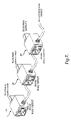
- FIG. 7 is a perspective diagram illustrating the use of several devices in a parallel configuration according to one embodiment of the invention.
- FIGS. 8A and 8B are perspective diagrams illustrating a device provided in one embodiment of the present invention that includes a power cord to be plugged into a receptacle of a powered device rather than plugging in an integrated output power connector directly into the receptacle;
- FIG. 9 is a circuit diagram illustrating aspects of another embodiment where power is not supplied to a second powered device.
- FIG. 10 is a circuit diagram illustrating a power supply utilized in one embodiment of the invention where power is not supplied to a second powered device.
- FIG. 11 is a circuit diagram illustrating a daisy chain connector provided by one embodiment of the present invention wherein power is not supplied to a second powered device.
- the apparatus comprises a housing 2 .
- the housing 2 is created from mold injected plastic or other type of suitable non-conducting material.
- the housing 2 includes an integrated power input connector 6 (also referred to as the “input connector” herein).
- the integrated power input connector 6 is operative to directly receive a power cord.
- the integrated power input connector 6 comprises an International Electrotechnical Commission (“IEC) IEC-320/C14 connector. It should also be appreciated that other types of connectors suitable for receiving a power cord may also be utilized.
- IEC International Electrotechnical Commission
- the housing 2 also comprises an integrated power output connector 4 (also referred to herein as the “output connector”).
- the integrated power output connector 4 is mounted directly to the housing 2 and is configured in a manner that allows the integrated power output connector 4 to be mated directly with a compatible input connector.
- the integrated power output connector 4 comprises an IEC-320/C13 connector that may be mated with an IEC-320/C14 connector utilized on many computer power supplies. In this manner, a power cord may be plugged directly into the integrated power input connector 6 and the integrated power output connector 4 may be plugged directly into the power receptacle of a powered device. It should be appreciated that other types of connectors may be utilized for the integrated power output connector 4 .
- the integrated power input connector 6 and the integrated power output connector 4 are electrically connected in series, thereby allowing electrical current applied at the integrated power input connector 6 to be passed directly through to the integrated power output connector 4 .
- a switch 8 may be mounted on and accessible from an external surface of the housing 2 and interposed between the integrated power input connector 6 and the integrated power output connector 4 . In this manner, the flow of electrical current between the integrated power input connector 6 and the integrated power output connector 4 may be controlled through the use of the switch 8 .
- the housing 2 may also contain a power supply for powering an external powered device other than the device connected to the integrated power output connector 4 .
- Power may be generated and delivered to the powered device through a cable assembly 10 extending from the housing 2 .
- the power supply may be utilized to provide power to a remote server management device, a USB hub, or other type of device.
- the switch 8 may be utilized to control the operation of the power supply. Additional details regarding the various embodiments of the invention will be provided below with respect to FIGS. 2–7 .
- the housing 2 includes an integrated power input connector 6 and an integrated power output connector 4 .
- the integrated power input connector 6 directly receives a power cord.
- the input connectors on the integrated power input connector 6 are connected in series to the appropriate connectors on the integrated power output connector 4 , thereby passing alternating electrical current (“AC”) applied at the input connector 6 to the output connector 4 .
- AC powered device such as the power supply of a computer system, may be directly powered by mating the power output connector 4 to the appropriate connector of the power supply.
- a switch 8 A may be interposed between the input connector 6 and the output connector 4 , thereby preventing the flow of current between the input connector 6 and the output connector 4 when in an open position.
- the switch 8 A may be mounted on and accessible from an external portion of the housing 2 . By using the switch 8 A, a user may easily remove power from the integrated power output connector 4 .
- the housing 2 may be utilized to store a power supply 12 .
- the power supply 12 may comprise a direct current (“DC”) power supply operative to generated power for powering an external device.
- the power supply 12 may be connected in parallel to the integrated power input connector 6 .
- the output of the power supply 12 may be supplied external to the housing 2 through a connected cable assembly 10 .
- the cable assembly and a terminating connector 14 compatible for use with a power input connector on a powered device may be utilized to provide power to the powered device.
- a switch 8 B may be interposed between the integrated power input connector 6 and the power supply 12 , thereby preventing the flow of current between the input connector 6 and the power supply 12 when in an open position.
- the switch 8 B may be mounted on and accessible from an external portion of the housing 2 . By using the switch 8 B, a user may easily remove supply power from the power supply 12 , thereby eliminating the output voltage of the power supply 12 . In this manner, the powered device may be conveniently turned on and off.
- the housing 2 includes an integrated power input connector 6 and an integrated power output connector 4 .
- the input connectors on the integrated power input connector 6 are connected in series to the appropriate connectors on the integrated power output connector 4 , thereby passing AC applied at the input connector 6 to the output connector 4 .
- an AC powered device such as the power supply of a computer system, may be directly powered by mating the power output connector 4 to the appropriate connector of the power supply.
- the housing 2 may be utilized to store a power supply 12 operative to generated power for powering an external device.
- the power supply 12 may be connected in parallel to the integrated power input connector 6 .
- the output of the power supply 12 may be supplied external to the housing 2 through a connected cable assembly 10 .
- the cable assembly and a terminating connector 14 compatible for use with a power input connector on a powered device may be utilized to provide power to the powered device.
- the housing 2 is also utilized to house a control circuit that receives an input signal and, based on the status of the input signal, either allows or prevents the flow of current between the input connector 6 and the output connector 4 .
- the housing 2 includes a relay control 18 and a relay 16 .
- the relay 16 is interposed between the input connector 6 and the output connector 4 .
- the relay control 18 comprises a circuit for controlling the operation of the relay 16 based upon the status of an input signal 19 .
- the input signal 19 as well as power generated by the power supply 12 , are exposed on the cable assembly and the terminating connector 14 . In this manner, the input signal 19 for controlling the operation of the relay 16 are available for control by external devices.
- an external device such as a remote server management device
- the power supply 12 comprises a DC power supply in one embodiment of the invention.
- the power supply 12 comprises a transformer 20 connected in parallel with the input connector 6 .
- the outputs of the transformer 20 are connected in series to a diode rectifier bridge 22 .
- the outputs of the diode rectifier bridge 22 are connected to a voltage regulator 24 .
- the DC power output of the voltage regulator 24 is then routed outside the housing 2 via the cable assembly 10 .
- the power output terminates at a terminating connector 14 that is compatible with a power input connector on a DC powered device.
- the power supply described herein is a DC power supply
- other types of power supplies may be utilized to power different types of devices.
- a universal power supply with a user-selectable voltage may be utilized in conjunction with a variety of differently sized terminating connectors 14 .
- the apparatus may be utilized to power a variety of devices having different voltage requirements.
- multiple cable assemblies may be utilized to power several devices concurrently.
- the relay control 18 provides an input signal 19 that may be utilized by an external device to control the operation of the relay 16 and, consequently, the delivery of power to the output connector 4 .
- a PNP transistor 26 is utilized as the basis for the relay control 18 .
- the emitter of the PNP transistor 26 is connected to voltage and the input signal 19 is connected to the base in conjunction with a pull-up resistor 28 .
- the input signal 19 is an open collector input.
- the collector of the PNP transistor 26 is connected to one input of the relay 16 .
- the other input of the relay 16 is connected to ground and a reverse voltage protection diode 30 is interposed between the inputs of the relay 16 .
- the PNP transistor 26 operates to open the relay 16 , thereby eliminating the flow of current between the input connector 6 and the output connector 4 .
- FIGS. 6A and 6B a cable assembly and daisy chain connector utilized in various embodiments of the invention will be described.
- the output of the power supply 12 may be provided to external devices through a cable assembly 10 .
- the cable assembly 10 is terminated with a terminating connector 14 that includes connectors for power and ground.
- the terminating connector 14 also includes a connector for the input signal 19 for controlling the relay control 18 .
- a single cable assembly 10 can be utilized to both power an external device and to expose the input signal 19 necessary for the external device to control the flow of power to the output connector 4 .
- the housing 2 also includes a daisy chain connector 32 .
- the daisy chain connector 32 provides an input connector for ground, power, and the input signal 19 .
- the connectors of the daisy chain connector 32 are connected in parallel to the output connectors of the terminating connector 14 , thereby creating a bus.
- the daisy chain connector 32 is compatible with the terminating connector 14 .
- multiple devices 2 A– 2 N may be daisy chained together. A single external powered device connected to the daisy chain may then control the power delivered by each of the devices. This may be useful, for instance, when a server computer utilizes multiple power supplies.
- the power supply in one device may drive the relay of another device in the event that the power supply in that device fails.
- the apparatus comprises a housing 2 ′.
- the housing 2 ′ is created from mold injected plastic or other type of suitable non-conducting material.
- the housing 2 ′ includes an integrated power input connector 6 such as the integrated power input connector 6 of FIGS. 1A and 1B .
- the integrated power input connector 6 is operative to directly receive a power cord.
- the integrated power input connector 6 comprises an International Electrotechnical Commission (“IEC) IEC- 320 /C14 connector. It should also be appreciated that other types of connectors suitable for receiving a power cord may also be utilized in this embodiment as well.
- IEC International Electrotechnical Commission
- the housing 2 ′ also comprises a power output cord 5 (also referred to herein as the “output cord”).
- the power output cord 5 may be mounted directly to the housing 2 ′ either as an integral component extending from the housing 2 ′ as shown in FIGS. 8A and 8B or alternatively as a separate component that plugs into a connector of the housing 2 ′.
- the housing 2 ′ may have an IEC-320/C14 for output and the power output cord 5 may have an IEC-320/C13 at one end for plugging into the IEC-320/C14 connector of the housing 2 ′ while having an IEC-320/C13 connector 4 ′ at the other distal end to plug into a receptacle of a powered device.
- the cord 5 is configured in a manner that allows the power output cord 5 to be mated at its distal end directly with a compatible input connector of a device.
- the power output cord 5 comprises the IEC-320/C13 connector 4 ′ on the end of the cord that may be mated with an IEC-320/C14 connector utilized on many computer power supplies.
- a power cord may be plugged directly into the integrated power input connector 6 and the connector 4 ′ of the power output cord 5 may be plugged directly into the power receptacle of a powered device. It should be appreciated that other types of connectors may be utilized for the connector 4 ′ of the power output cord 5 .
- the integrated power input connector 6 and the power output cord 5 are electrically connected in series, thereby allowing electrical current applied at the integrated power input connector 6 to be passed directly through to the power output cord 5 .
- a switch 8 may be mounted on and accessible from an external surface of the housing 2 ′ and interposed between the integrated power input connector 6 and the power output cord 5 . In this manner, the flow of electrical current between the integrated power input connector 6 and the power output cord 5 may be controlled through the use of the switch 8 .
- the housing 2 ′ may also contain a power supply for powering an external powered device other than the device connected to the power output cord 5 .
- Power may be generated and delivered to the powered device through a cable assembly 10 extending from the housing 2 ′.
- the power supply may be utilized to provide power to a remote server management device, a USB hub, or other type of device.
- the switch 8 may be utilized to control the operation of the power supply.
- the housing 2 or 2 ′ includes an integrated power input connector 6 and an integrated power output connector 4 or power output cord 5 .
- the input connectors on the integrated power input connector 6 are connected in series to the appropriate connectors on the integrated power output connector 4 or power output cord 5 , thereby passing AC applied at the input connector 6 to the output connector 4 or 4 ′.
- an AC powered device such as the power supply of a computer system, may be directly powered by mating the power output connector 4 or 4 ′ to the appropriate connector of the power supply.
- the housing 2 or 2 ′ may be utilized to store a power supply 12 ′ operative to generate power for powering only the control circuit for a remote controlled switch rather than also providing power to an external device.
- the external device that provides an input signal to control the remote controlled switch has its own power supply and does not need to be supplied power from the device that the control signal is being provided to.
- the power supply 12 ′ may be connected in parallel to the integrated power input connector 6 .
- the output of the power supply 12 ′ is not supplied external to the housing 2 through a connected cable assembly 10 in this embodiment.
- the cable assembly and a terminating connector 14 compatible for use with a power input connector on a powered device is not utilized to provide power to the powered device but instead only carries the input signal and may also carry a ground connection.
- the housing 2 or 2 ′ is also utilized to house a control circuit that receives the input signal and, based on the status of the input signal, either allows or prevents the flow of current between the input connector 6 and the output connector 4 or 4 ′.
- the housing 2 or 2 ′ includes a relay control 18 and a relay 16 .
- the relay 16 is interposed between the input connector 6 and the output connector 4 or 4 ′.
- the relay control 18 comprises a circuit for controlling the operation of the relay 16 based upon the status of an input signal 19 .
- the input signal 19 is exposed on the cable assembly and the terminating connector 14 . In this manner, the input signal 19 for controlling the operation of the relay 16 is available for control by external devices.
- an external device such as a remote server management device
- the power supply 12 ′ comprises a DC power supply in one embodiment of the invention.
- the power supply 12 ′ comprises a transformer 20 ′ connected in parallel with the input connector 6 .
- the outputs of the transformer 20 ′ are connected in series to a diode rectifier bridge 22 .
- the outputs of the diode rectifier bridge 22 are connected to a voltage regulator 24 ′.
- the DC power output of the voltage regulator 24 ′ is then routed only to the relay control circuit, rather than outside the housing 2 or 2 ′ via the cable assembly 10 .
- the power supply 12 ′ is not required to provide power to one or more external devices but instead provides power only to the relay control circuit 18 , the power supply 12 ′ has a lesser electrical load such that the power supply 12 ′ may be simplified.
- the transformer 20 ′ may have a significantly smaller current rating than a transformer 20 that must be capable of supplying current to. one or more external devices.
- the voltage regulator 24 ′ may be of a relatively more complex transistor form, or may be a relatively simplified transistor-less form using only a Zener diode that may also include filtering capacitors.
- the power supply 12 ′ may be provided in a condensed size allowing the housing 2 or 2 ′ to be smaller in size and allowing the overall apparatus contained within the housing 2 or 2 ′ to be more cost efficient.
- the input signal may be received from external devices through a cable assembly 10 .
- the cable assembly 10 is terminated with a terminating connector 14 ′ that includes a connector for ground and also includes a connector for the input signal 19 for controlling the relay control 18 .
- a cable assembly 10 can be utilized to expose the input signal 19 necessary for the external device to control the flow of power to the output connector 4 or 4 ′.
- the housing 2 also includes a daisy chain connector 32 .
- the daisy chain connector 32 provides an input connector for ground and the input signal 19 .
- the connectors of the daisy chain connector 32 are connected in parallel to the output connectors of the terminating connector 14 ′, thereby creating a bus.
- the daisy chain connector 32 is compatible with the terminating connector 14 ′.
- multiple devices 2 A– 2 N may be daisy chained together. A single external device connected to the daisy chain may then control the power delivered by each of the devices.
- embodiments of the invention provide an in-line remote controllable power switch with an integrated power supply.
- the above specification, examples and data provide a complete description of the manufacture and use of the composition of the invention. Since many embodiments of the invention can be made without departing from the spirit and scope of the invention, the invention resides in the claims hereinafter appended.
Abstract
Description
Claims (23)
Priority Applications (1)
| Application Number | Priority Date | Filing Date | Title |
|---|---|---|---|
| US10/780,795 US7198520B1 (en) | 2003-01-15 | 2004-02-18 | In-line remote controllable power switch |
Applications Claiming Priority (2)
| Application Number | Priority Date | Filing Date | Title |
|---|---|---|---|
| US10/342,501 US6875059B2 (en) | 2003-01-15 | 2003-01-15 | In-line remote controllable power switch with integrated power supply |
| US10/780,795 US7198520B1 (en) | 2003-01-15 | 2004-02-18 | In-line remote controllable power switch |
Related Parent Applications (1)
| Application Number | Title | Priority Date | Filing Date |
|---|---|---|---|
| US10/342,501 Continuation-In-Part US6875059B2 (en) | 2003-01-15 | 2003-01-15 | In-line remote controllable power switch with integrated power supply |
Publications (1)
| Publication Number | Publication Date |
|---|---|
| US7198520B1 true US7198520B1 (en) | 2007-04-03 |
Family
ID=32711725
Family Applications (2)
| Application Number | Title | Priority Date | Filing Date |
|---|---|---|---|
| US10/342,501 Expired - Lifetime US6875059B2 (en) | 2003-01-15 | 2003-01-15 | In-line remote controllable power switch with integrated power supply |
| US10/780,795 Expired - Lifetime US7198520B1 (en) | 2003-01-15 | 2004-02-18 | In-line remote controllable power switch |
Family Applications Before (1)
| Application Number | Title | Priority Date | Filing Date |
|---|---|---|---|
| US10/342,501 Expired - Lifetime US6875059B2 (en) | 2003-01-15 | 2003-01-15 | In-line remote controllable power switch with integrated power supply |
Country Status (1)
| Country | Link |
|---|---|
| US (2) | US6875059B2 (en) |
Cited By (1)
| Publication number | Priority date | Publication date | Assignee | Title |
|---|---|---|---|---|
| US20070198100A1 (en) * | 2005-10-06 | 2007-08-23 | Purifics Environmental Technologies, Inc. | Hybrid field device cabling with industrial network and operating power |
Families Citing this family (16)
| Publication number | Priority date | Publication date | Assignee | Title |
|---|---|---|---|---|
| SE525187C2 (en) * | 2003-03-10 | 2004-12-21 | Atlas Copco Tools Ab | Tool system comprising a multipart cable with an electronic memory |
| US20050013081A1 (en) * | 2003-07-17 | 2005-01-20 | Gilbert Daniel A. | Electronic appliance switch adapter |
| US20060063411A1 (en) * | 2004-09-23 | 2006-03-23 | Tyco Electronics Power Systems, Inc., A Nevada Corporation | Floating power connector mount for a power converter |
| DE102005061845B4 (en) * | 2005-12-23 | 2013-07-18 | Siemens Aktiengesellschaft | Device for powering field devices |
| GB2457217A (en) * | 2007-04-11 | 2009-08-12 | Baruch Entpr Ltd | Cascadable electrical connector |
| US7682198B1 (en) * | 2007-12-13 | 2010-03-23 | Plattner Wesley M | Power adapter for an aircraft |
| US20110151718A1 (en) * | 2008-01-03 | 2011-06-23 | Sheng-Fu Lu | AC adapter capable of connecting external AC power |
| US7722406B2 (en) * | 2008-03-17 | 2010-05-25 | Zippy Technology Corp. | Output adapting device of plug-in power system |
| US7794283B2 (en) * | 2009-02-05 | 2010-09-14 | Ting Shen Industrial Co., Ltd | Socket, plug, and adaptor combination with waterproof arrangement |
| US8179004B2 (en) * | 2009-11-06 | 2012-05-15 | Shop Vac Corporation | Motor assembly with switch module |
| CN102279626A (en) * | 2010-06-08 | 2011-12-14 | 鸿富锦精密工业(深圳)有限公司 | Electronic equipment chassis and power supply device thereof |
| CN102403626B (en) * | 2010-09-13 | 2016-01-27 | 胜德国际研发股份有限公司 | Identifiable plug and combination thereof |
| CN102739075A (en) * | 2011-04-07 | 2012-10-17 | 鸿富锦精密工业(深圳)有限公司 | Power adapter |
| TW201241598A (en) * | 2011-04-07 | 2012-10-16 | Hon Hai Prec Ind Co Ltd | Power adapter |
| US8878390B2 (en) * | 2011-04-22 | 2014-11-04 | David Lee Lorentzen | Adaptor for adding a second power supply unit to a computer system |
| CN103986031A (en) * | 2014-05-09 | 2014-08-13 | 广西南宁百兰斯科技开发有限公司 | Lightning-protection power line |
Citations (13)
| Publication number | Priority date | Publication date | Assignee | Title |
|---|---|---|---|---|
| US5563782A (en) * | 1994-11-10 | 1996-10-08 | At&T Global Information Solutions Company | Wall outlet with direct current output |
| US5732212A (en) | 1992-10-23 | 1998-03-24 | Fox Network Systems, Inc. | System and method for remote monitoring and operation of personal computers |
| US5907197A (en) * | 1997-06-30 | 1999-05-25 | Compaq Computer Corporation | AC/DC portable power connecting architecture |
| US5910750A (en) * | 1997-09-29 | 1999-06-08 | Mitsubishi Denki Kabushiki Kaisha | Low power consumption switching device for power source |
| US5961619A (en) * | 1997-09-10 | 1999-10-05 | Cisco Technology, Inc. | Method and apparatus for automatic activation of bus termination on a fast ethernet repeater stack |
| US6057610A (en) | 1997-05-21 | 2000-05-02 | Selfcharge Inc. | Lighter plug DC outlet and single AC and DC plug with adapter circuit |
| US6160728A (en) * | 1999-05-26 | 2000-12-12 | Advanced Micro Devices, Inc. | Dual-mode AC/DC electrical receptacle |
| US6304895B1 (en) | 1997-08-22 | 2001-10-16 | Apex Inc. | Method and system for intelligently controlling a remotely located computer |
| US6362610B1 (en) * | 2001-08-14 | 2002-03-26 | Fu-I Yang | Universal USB power supply unit |
| US6465913B1 (en) | 1999-09-28 | 2002-10-15 | Sony Corporation | Power source unit |
| US20030103304A1 (en) * | 2001-12-03 | 2003-06-05 | Rendic Neven V. | Outlet strip controlled by PC using low voltage powertap |
| US6628535B1 (en) * | 2002-03-20 | 2003-09-30 | Formosa Electronic Industries Inc. | Voltage converter with selectable DC output voltage level |
| US6664758B2 (en) * | 2002-03-29 | 2003-12-16 | Fu-I Yang | Universal power adapter |
-
2003
- 2003-01-15 US US10/342,501 patent/US6875059B2/en not_active Expired - Lifetime
-
2004
- 2004-02-18 US US10/780,795 patent/US7198520B1/en not_active Expired - Lifetime
Patent Citations (13)
| Publication number | Priority date | Publication date | Assignee | Title |
|---|---|---|---|---|
| US5732212A (en) | 1992-10-23 | 1998-03-24 | Fox Network Systems, Inc. | System and method for remote monitoring and operation of personal computers |
| US5563782A (en) * | 1994-11-10 | 1996-10-08 | At&T Global Information Solutions Company | Wall outlet with direct current output |
| US6057610A (en) | 1997-05-21 | 2000-05-02 | Selfcharge Inc. | Lighter plug DC outlet and single AC and DC plug with adapter circuit |
| US5907197A (en) * | 1997-06-30 | 1999-05-25 | Compaq Computer Corporation | AC/DC portable power connecting architecture |
| US6304895B1 (en) | 1997-08-22 | 2001-10-16 | Apex Inc. | Method and system for intelligently controlling a remotely located computer |
| US5961619A (en) * | 1997-09-10 | 1999-10-05 | Cisco Technology, Inc. | Method and apparatus for automatic activation of bus termination on a fast ethernet repeater stack |
| US5910750A (en) * | 1997-09-29 | 1999-06-08 | Mitsubishi Denki Kabushiki Kaisha | Low power consumption switching device for power source |
| US6160728A (en) * | 1999-05-26 | 2000-12-12 | Advanced Micro Devices, Inc. | Dual-mode AC/DC electrical receptacle |
| US6465913B1 (en) | 1999-09-28 | 2002-10-15 | Sony Corporation | Power source unit |
| US6362610B1 (en) * | 2001-08-14 | 2002-03-26 | Fu-I Yang | Universal USB power supply unit |
| US20030103304A1 (en) * | 2001-12-03 | 2003-06-05 | Rendic Neven V. | Outlet strip controlled by PC using low voltage powertap |
| US6628535B1 (en) * | 2002-03-20 | 2003-09-30 | Formosa Electronic Industries Inc. | Voltage converter with selectable DC output voltage level |
| US6664758B2 (en) * | 2002-03-29 | 2003-12-16 | Fu-I Yang | Universal power adapter |
Cited By (1)
| Publication number | Priority date | Publication date | Assignee | Title |
|---|---|---|---|---|
| US20070198100A1 (en) * | 2005-10-06 | 2007-08-23 | Purifics Environmental Technologies, Inc. | Hybrid field device cabling with industrial network and operating power |
Also Published As
| Publication number | Publication date |
|---|---|
| US6875059B2 (en) | 2005-04-05 |
| US20040137796A1 (en) | 2004-07-15 |
Similar Documents
| Publication | Publication Date | Title |
|---|---|---|
| US7198520B1 (en) | In-line remote controllable power switch | |
| US10084272B1 (en) | Modular electrical receptacle | |
| US7392410B2 (en) | Power adapter having power supply identifier information functionality | |
| US6445088B1 (en) | Multipurpose data port | |
| US8645720B2 (en) | Power adaptor detection system | |
| JPH03223915A (en) | Power supply system and equipment connection system | |
| US20110121662A1 (en) | Power supply and power supplying system with remote power management function | |
| US20070049120A1 (en) | Active cable assembly for use in universal serial bus | |
| JP6022582B2 (en) | Power adapter and method for adapting the power of electronic devices | |
| US10531530B2 (en) | Controlling a power adaptor light-emitting diode (LED) indicator | |
| US7294976B1 (en) | Split power supply subsystem with isolated voltage supplies to satisfy a predetermined power limit | |
| US6590986B1 (en) | Patient-isolating programming interface for programming hearing aids | |
| CN110502088B (en) | Battery power supply protection device and server | |
| US20030008565A1 (en) | Serial advanced technology adapter power connector adapter | |
| US6266220B1 (en) | Internal surge protector device | |
| US20070134986A1 (en) | Active enclosure for use in power over ethernet powered device | |
| GB2327819A (en) | Power controller for a computer peripheral | |
| CN213213322U (en) | Power supply conversion system | |
| WO2000059079A1 (en) | Intelligent power board | |
| CN114629328A (en) | Enhanced power supply device and power supply method for intelligently adjusting output voltage | |
| KR200159572Y1 (en) | Power supply device in a portable computer | |
| US8710698B2 (en) | Redundant power delivery | |
| CN211506363U (en) | Quick-charging output case | |
| CN110989812B (en) | Encryption device, system and encryption device control method | |
| US20040210783A1 (en) | Monitor |
Legal Events
| Date | Code | Title | Description |
|---|---|---|---|
| AS | Assignment |
Owner name: AMERICAN MEGATRENDS, INC., GEORGIA Free format text: ASSIGNMENT OF ASSIGNORS INTEREST;ASSIGNOR:SIVERTSEN, CLAS G.;REEL/FRAME:015006/0889 Effective date: 20040211 |
|
| STCF | Information on status: patent grant |
Free format text: PATENTED CASE |
|
| FEPP | Fee payment procedure |
Free format text: PAT HOLDER NO LONGER CLAIMS SMALL ENTITY STATUS, ENTITY STATUS SET TO UNDISCOUNTED (ORIGINAL EVENT CODE: STOL); ENTITY STATUS OF PATENT OWNER: LARGE ENTITY |
|
| REFU | Refund |
Free format text: REFUND - SURCHARGE, PETITION TO ACCEPT PYMT AFTER EXP, UNINTENTIONAL (ORIGINAL EVENT CODE: R2551); ENTITY STATUS OF PATENT OWNER: LARGE ENTITY |
|
| FPAY | Fee payment |
Year of fee payment: 4 |
|
| FPAY | Fee payment |
Year of fee payment: 8 |
|
| MAFP | Maintenance fee payment |
Free format text: PAYMENT OF MAINTENANCE FEE, 12TH YEAR, LARGE ENTITY (ORIGINAL EVENT CODE: M1553); ENTITY STATUS OF PATENT OWNER: LARGE ENTITY Year of fee payment: 12 |
|
| AS | Assignment |
Owner name: AMZETTA TECHNOLOGIES, LLC,, GEORGIA Free format text: ASSIGNMENT OF ASSIGNORS INTEREST;ASSIGNOR:AMERICAN MEGATRENDS INTERNATIONAL, LLC,;REEL/FRAME:053007/0151 Effective date: 20190308 Owner name: AMERICAN MEGATRENDS INTERNATIONAL, LLC, GEORGIA Free format text: CHANGE OF NAME;ASSIGNOR:AMERICAN MEGATRENDS, INC.;REEL/FRAME:053007/0233 Effective date: 20190211 |