US7222518B2 - Transformer monitoring system - Google Patents
Transformer monitoring system Download PDFInfo
- Publication number
- US7222518B2 US7222518B2 US11/417,413 US41741306A US7222518B2 US 7222518 B2 US7222518 B2 US 7222518B2 US 41741306 A US41741306 A US 41741306A US 7222518 B2 US7222518 B2 US 7222518B2
- Authority
- US
- United States
- Prior art keywords
- oil temperature
- oil
- transformer
- equation
- temperature
- Prior art date
- Legal status (The legal status is an assumption and is not a legal conclusion. Google has not performed a legal analysis and makes no representation as to the accuracy of the status listed.)
- Expired - Fee Related
Links
Images


Classifications
-
- G—PHYSICS
- G01—MEASURING; TESTING
- G01N—INVESTIGATING OR ANALYSING MATERIALS BY DETERMINING THEIR CHEMICAL OR PHYSICAL PROPERTIES
- G01N33/00—Investigating or analysing materials by specific methods not covered by groups G01N1/00 - G01N31/00
- G01N33/26—Oils; viscous liquids; paints; inks
- G01N33/28—Oils, i.e. hydrocarbon liquids
-
- H—ELECTRICITY
- H01—ELECTRIC ELEMENTS
- H01F—MAGNETS; INDUCTANCES; TRANSFORMERS; SELECTION OF MATERIALS FOR THEIR MAGNETIC PROPERTIES
- H01F27/00—Details of transformers or inductances, in general
- H01F27/40—Structural association with built-in electric component, e.g. fuse
- H01F27/402—Association of measuring or protective means
- H01F2027/404—Protective devices specially adapted for fluid filled transformers
Definitions
- the present invention relates to a monitoring of a state of oil-filled transformers using information such as transformer oil temperature, current and ambient temperature.
- a stable supply of electricity is important and it is therefore necessary to periodically monitor transformers to forestall possible failures.
- monitoring a voltage, current and oil temperature of the transformers is effective.
- the monitoring of the oil temperature generally involves estimating an oil temperature from an average load factor, visually checking a temperature reading on a thermometer, comparing the estimated oil temperature with the temperature reading on the thermometer to decide whether the transformer in question is normal or not, and at the same time checking if the temperature reading on the thermometer has exceeded a predetermined value.
- thermometer with an alarm contact which issues an alarm for detection of an anomaly when the oil temperature exceeds a set temperature.
- JP-A-5-227644 Another method of monitoring is disclosed, for instance, in JP-A-5-227644 which, when determining a remaining service life from a maximum winding temperature, calculates an oil temperature rise and determines an oil temperature by adding a measured ambient temperature to the oil temperature rise.
- a means that calculates a transformer oil temperature from a reading on a thermometer attached to the outside of a case of the oil-filled transformer and from a measured load factor of the transformer.
- JIS C 4304 specifies that a limit of an oil temperature rise is 50K at maximum during the rated load operation and that the transformer can be used in an ambient temperature range of between ⁇ 20° C. and 40° C. Thus, to precisely estimate the oil temperature requires considering influences of ambient temperature.
- the conventional technique does not consider ambient temperature variations when indirectly measuring the oil temperature from the case outer surface temperature, an error occurs between the measured value and the converted value if the ambient temperature changes sharply.
- the converted value is based on a case measured value, which indirectly measures the oil temperature, since the measured value constitutes a reference, it is not possible to estimate accurately what the true oil temperature is.
- the transformer monitoring system of this invention comprises: a current measuring means to measure a current in an oil-filled transformer; an ambient temperature measuring means; an oil temperature calculation means to calculate an oil temperature of the oil-filled transformer using measurements from the current measuring means and the ambient temperature measuring means; an oil temperature measuring means to measure the oil temperature of the oil-filled transformer; a comparison means to compare the calculated oil temperature and the measured oil temperature; and an oil temperature anomaly decision means to decide that there is an abnormal condition when a difference between the calculated oil temperature and the measured oil temperature exceeds a set value.
- the transformer monitoring system also has an inner pressure measuring means and an inner pressure anomaly decision means to check an inner pressure value obtained from the inner pressure measuring means to decide whether the inner pressure is abnormal or not.
- the transformer monitoring system also includes a voltage measuring means and a voltage anomaly decision means to check a voltage value obtained from the voltage measuring means to decide whether the voltage is abnormal or not.
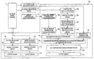
- FIG. 1 is a block diagram of an oil-filled transformer monitoring system.
- FIG. 2 is a graph showing an instantaneous oil temperature rise when a load factor of the oil-filled transformer changes and an oil temperature rise converted value.
- FIG. 3 is a graph showing an ambient temperature when the ambient temperature of the oil-filled transformer changes and a virtual ambient temperature.
- FIG. 4 is a graph showing an oil temperature rise of the oil-filled transformer, a virtual ambient temperature, an oil temperature converted value, and a measured oil temperature.
- FIG. 1 is a block diagram of an oil-filled transformer monitoring system.
- reference number 1 represents an oil-filled transformer
- 2 a current measuring means constructed of a current transformer (CT) for metering current of the transformer
- 3 an ambient temperature measuring means constructed of a temperature measuring resistor (search coil) for measuring an ambient temperature
- 4 a a load factor calculation means for calculating a load factor from a signal output from the current measuring means 2
- 4 b a loss calculation means for calculating a loss from a result produced by the load factor calculation means 4 a
- 4 c an instantaneous oil temperature rise calculation means for calculating an instantaneous oil temperature rise from a result produced by the loss calculation means 4 b
- 4 d an oil temperature rise calculation means for calculating an oil temperature rise from a result produced by the instantaneous oil temperature rise calculation means 4 c
- 5 a a measured ambient temperature conversion means for converting an output signal from the ambient temperature measuring means 3 into an ambient temperature measured value
- 5 b a virtual ambient temperature calculation means for calculating a virtual ambient temperature from a result produced by the measured ambient
- FIG. 2 shows a load factor 19 , an instantaneous oil temperature rise 20 and an oil temperature rise converted value 21 for the oil-filled transformer in this embodiment.
- the load factor 19 of the oil-filled transformer is calculated from an output signal from the current measuring means 2 of FIG. 1 by the load factor calculation means 4 a.
- the instantaneous oil temperature rise 20 is calculated from the load factor 19 of the oil-filled transformer by the instantaneous oil temperature rise calculation means 4 c.
- the instantaneous oil temperature rise 20 is further processed by the oil temperature rise calculation means 4 d to determine the oil temperature rise converted value 21 .
- FIG. 3 shows an ambient temperature 22 of the oil-filled transformer of this embodiment as it changes and a virtual ambient temperature 23 converted from the ambient temperature 22 .
- the ambient temperature 22 is an output signal from the measured ambient temperature conversion means 5 a and the virtual ambient temperature 23 is obtained by processing the ambient temperature 22 by the virtual ambient temperature calculation means 5 b.
- FIG. 4 shows an oil temperature converted value 24 for the oil-filled transformer of this embodiment, which is a sum of the oil temperature rise converted value 21 and the virtual ambient temperature 23 .
- FIG. 4 also shows a measured oil temperature 25 of the oil-filled transformer.
- ⁇ Ai (t) represents a virtual ambient temperature of FIG. 2 and FIG. 3 and ⁇ mi(t) represents an oil temperature rise converted value shown in FIG. 1 and FIG. 3 .
- T A [minutes] is a time constant of an oil temperature with respect to the ambient temperature
- ⁇ A ( ⁇ nt) [° C.] is an ambient temperature nxt minutes earlier
- t [minutes] is a monitoring interval
- n is the number of past measurements used for calculation.
- T 0
- T n ⁇ ( ⁇ 1 - e - [ ( T ) ⁇ t Tm ] ⁇ - ⁇ 1 - e - [ ( T + 1 ) ⁇ t Tm ] ⁇ ) ⁇ ⁇ ⁇ mu ⁇ ( - Tt ) ( 3 )
- Tm [minutes] is a time constant of an oil temperature with respect to a total loss
- ⁇ mu( ⁇ nt) [K] is an oil temperature rise nxt minutes earlier in a steady state at a load factor of m %.
- the oil temperature rise ⁇ mu( ⁇ nt) is the instantaneous oil temperature rise 20 of FIG. 2 and expressed as follows.
- ⁇ ⁇ mu ⁇ ⁇ ( - nt ) ⁇ ⁇ ou ⁇ [ Wi + Wc ⁇ ( m ⁇ ⁇ ( - nt ) 100 ) 2 Wi + Wc ] k ( 4 )
- ⁇ ou [K] is an oil temperature rise in a steady state at a rated (100%) load
- m( ⁇ nt) [%] is an instantaneous load factor nxt minutes earlier
- Wi [W] is a no-load loss
- Wc [W] is a load loss at the rated (100%) load
- k is a constant.
- the instantaneous load factor m( ⁇ nt) is expressed as follows.
- m ⁇ ⁇ ( - nt ) i ⁇ ⁇ ( - nt ) Is ⁇ 100 ⁇ ⁇ ( % ) ( 5 )
- I( ⁇ nt) [A] is a secondary instantaneous current nxt minutes earlier and Is [A] is a secondary rated current.
- the secondary rated current is expressed as follows.
- Is P Es ⁇ 1 F ( 6 )
- Es [V] is a secondary rated voltage
- P [kVA] is a transformer rated capacity
- F [phase] is the number of transformer phases
- t is an interval of measurement.
- the oil temperature of the oil-filled transformer can be estimated with high precision, it is possible to predict an oil temperature change by assuming an appropriate load factor and ambient temperature. Therefore, if the oil temperature is expected to exceed a set value, the load can be changed or switched to other power system in advance. Other countermeasures can be taken in advance, such as performing ventilation to lower the ambient temperature.
- an abnormal condition occurs in connected portions of circuit within coil and case as a result of progressive degradations over time or vibrations caused by earthquakes
- the anomaly in the transformer such as abnormal voltage and abnormal inner pressure, can be detected immediately, contributing greatly to the supervision of the oil-filled transformer.
Abstract
An oil-filled transformer monitoring system is provided which calculates an oil temperature of an oil-filled transformer with high precision from a current of the transformer and an ambient temperature. The oil-filled transformer monitoring system of this invention has an oil temperature calculation device to calculate a transformer oil temperature using measurements from a transformer current measuring device and an ambient temperature measuring device. The transformer monitoring system also has an oil temperature measuring device and compares an output value from the oil temperature calculation device with an output value from the oil temperature measuring device to detect any anomaly.
Description
This application is a continuation of U.S. patent application Ser. No. 10/896,097, filed Jul. 20, 2004, now U.S. Pat. No. 7,140,237, entitled “Transformer Monitoring System,” which claims priority from Japanese application JP 2004-112651, filed on Apr. 7, 2004, each of which is hereby incorporated herein by reference.
The present invention relates to a monitoring of a state of oil-filled transformers using information such as transformer oil temperature, current and ambient temperature.
A stable supply of electricity is important and it is therefore necessary to periodically monitor transformers to forestall possible failures. For this purpose, monitoring a voltage, current and oil temperature of the transformers is effective. The monitoring of the oil temperature generally involves estimating an oil temperature from an average load factor, visually checking a temperature reading on a thermometer, comparing the estimated oil temperature with the temperature reading on the thermometer to decide whether the transformer in question is normal or not, and at the same time checking if the temperature reading on the thermometer has exceeded a predetermined value.
Another practice involves the use of a thermometer with an alarm contact which issues an alarm for detection of an anomaly when the oil temperature exceeds a set temperature.
Another method of monitoring is disclosed, for instance, in JP-A-5-227644 which, when determining a remaining service life from a maximum winding temperature, calculates an oil temperature rise and determines an oil temperature by adding a measured ambient temperature to the oil temperature rise.
In another method disclosed in JP-A-8-213246, a means is provided that calculates a transformer oil temperature from a reading on a thermometer attached to the outside of a case of the oil-filled transformer and from a measured load factor of the transformer.
In the above conventional method using a visual check, however, since an oil temperature change lags load factor and ambient temperature changes, checking the measured temperature after the load factor or ambient temperature has changed cannot easily determine if it is a proper temperature or not.
Further, JIS C 4304 specifies that a limit of an oil temperature rise is 50K at maximum during the rated load operation and that the transformer can be used in an ambient temperature range of between −20° C. and 40° C. Thus, to precisely estimate the oil temperature requires considering influences of ambient temperature.
When the oil temperature exceeds the set temperature of the thermometer with an alarm contact, an alarm is issued for detection of an anomaly. However, since the oil temperature is a sum of a temperature rise caused by a transformer loss and a temperature rise caused by the ambient temperature, if the ambient temperature is low, the oil temperature will not reach the set temperature even during an overload operation. Further, even when the transformer is used below the rated load, an alarm may be issued if the ambient temperature is high and the set temperature is exceeded. This method therefore could not decide whether the oil temperature is correct or not.
Nor can the conventional monitoring system determine if the oil temperature is correct or not.
Further, since the above conventional technique uses a measured value for the ambient temperature in determining the maximum winding temperature, the fact is not taken into account that an oil temperature change lags behind an ambient temperature change.
Further, since the conventional technique does not consider ambient temperature variations when indirectly measuring the oil temperature from the case outer surface temperature, an error occurs between the measured value and the converted value if the ambient temperature changes sharply. Moreover, when the converted value is based on a case measured value, which indirectly measures the oil temperature, since the measured value constitutes a reference, it is not possible to estimate accurately what the true oil temperature is.
Therefore, if an abnormal condition occurs in connected portions of circuit within coil and case as a result of progressive degradations over time or vibrations caused by earthquakes, oil is heated and its temperature rises. However, since the true oil temperature cannot be estimated accurately, it is not possible to decide that an abnormal condition has occurred inside the transformer.
It is an object of the present invention to provide a transformer monitoring system which can solve the aforementioned problems experienced with conventional systems and which can calculate with high precision an oil temperature of an oil-filled transformer from an ambient temperature and a transformer current, monitor the oil-filled transformer by using the calculated oil temperature and a measured oil temperature of the transformer, and also monitor an inner pressure and voltage.
To achieve the above objective, the transformer monitoring system of this invention comprises: a current measuring means to measure a current in an oil-filled transformer; an ambient temperature measuring means; an oil temperature calculation means to calculate an oil temperature of the oil-filled transformer using measurements from the current measuring means and the ambient temperature measuring means; an oil temperature measuring means to measure the oil temperature of the oil-filled transformer; a comparison means to compare the calculated oil temperature and the measured oil temperature; and an oil temperature anomaly decision means to decide that there is an abnormal condition when a difference between the calculated oil temperature and the measured oil temperature exceeds a set value.
The transformer monitoring system also has an inner pressure measuring means and an inner pressure anomaly decision means to check an inner pressure value obtained from the inner pressure measuring means to decide whether the inner pressure is abnormal or not.
The transformer monitoring system also includes a voltage measuring means and a voltage anomaly decision means to check a voltage value obtained from the voltage measuring means to decide whether the voltage is abnormal or not.
Other objects, features and advantages of the invention will become apparent from the following description of the embodiments of the invention taken in conjunction with the accompanying drawings.
A system for monitoring an oil-filled transformer as one embodiment of this invention will be described by referring to the accompanying drawings.
In FIG. 1 , reference number 1 represents an oil-filled transformer; 2 a current measuring means constructed of a current transformer (CT) for metering current of the transformer; 3 an ambient temperature measuring means constructed of a temperature measuring resistor (search coil) for measuring an ambient temperature; 4 a a load factor calculation means for calculating a load factor from a signal output from the current measuring means 2; 4 b a loss calculation means for calculating a loss from a result produced by the load factor calculation means 4 a; 4 c an instantaneous oil temperature rise calculation means for calculating an instantaneous oil temperature rise from a result produced by the loss calculation means 4 b; 4 d an oil temperature rise calculation means for calculating an oil temperature rise from a result produced by the instantaneous oil temperature rise calculation means 4 c; 5 a a measured ambient temperature conversion means for converting an output signal from the ambient temperature measuring means 3 into an ambient temperature measured value; 5 b a virtual ambient temperature calculation means for calculating a virtual ambient temperature from a result produced by the measured ambient temperature conversion means 5 a; 6 an oil temperature calculation means for calculating an oil temperature from the oil temperature rise calculation means 4 d and the virtual ambient temperature calculation means 5 b; 7 an oil temperature measuring means constructed of a temperature measuring resistor (search coil) to measure the actual oil temperature in a tank of the transformer; 8 a measured oil temperature conversion means for converting an output from the oil temperature measuring means 7 into an oil temperature measured value; 9 a comparison means for comparing a calculated oil temperature value from the oil temperature calculation means 6 and a measured oil temperature from the measured oil temperature conversion means 8; 10 an oil temperature anomaly decision means for deciding that the oil temperature is abnormal when a difference between the calculated oil temperature value and the measured value exceeds a set value and for checking if the result produced by the measured oil temperature conversion means 8 is in excess of an oil temperature upper limit set value; 11 an output means for outputting an anomaly signal when the oil temperature anomaly decision means 10 decides that the oil temperature is abnormal; 12 an inner pressure measuring means constructed a pressure sensor to measure an inner pressure in the oil-filled transformer tank; 13 an anomaly decision means for converting a signal from the inner pressure measuring means 12 into a pressure and checking if the calculated inner pressure is in excess of an upper limit set value; 14 an output means for outputting an anomaly signal when the inner pressure anomaly decision means 13 decides that the inner pressure is abnormal; 15 a voltage measuring means constructed of a voltage transformer (VT) to measure a voltage of the transformer; 16 an anomaly decision means for converting a signal from the voltage measuring means 15 into a voltage and checking if the converted voltage is in excess of an upper limit set value and also if it is less than a lower limit set value; and 17 an output means for outputting an anomaly signal when the voltage anomaly decision means 16 decides that the voltage is abnormal.
Next, by referring to the system block diagram of FIG. 1 , how signals are produced and processed at various parts with elapse of time will be explained.
It is seen from FIG. 4 that the oil temperature converted value 24 obtained from the current of the oil-filled transformer and the ambient temperature shows a good agreement with the measured oil temperature 25 and that the oil temperature is converted highly precisely.
In this system, if an abnormal condition occurs in connected portions of circuit such as terminals, as a result of progressive degradations over time or vibrations caused by earthquakes, and a contact resistance increases, a difference occurs between the oil temperature converted value 24 and the measured oil temperature 25 since the current flowing on the secondary side normally does not change.
This means it is possible to calculate the difference between the converted value and the measured value of the oil temperature by the comparison means 9 in the system block diagram of FIG. 1 and, if the difference is greater than a set value, to output a signal to an output means to issue an alarm annunciating the anomaly. It is also possible to set a desired load factor and ambient temperature and thereby estimate how the oil temperature will change. If it is found that the oil temperature is about to exceed the set upper limit temperature, it is possible to change the load or switch it to other power system in advance. Alternatively, ventilation may be performed to lower the ambient temperature in advance.
Next, a process of calculation performed by the monitoring system of FIG. 1 will be explained.
Let the oil temperature converted value 24 output from the oil temperature calculation means 6 be θoc(t). It is expressed as follows:
θoc(t)=θAi(t)+θmi(t) (1)
where θoc(t) [° C.] is an oil temperature t minutes later.
θoc(t)=θAi(t)+θmi(t) (1)
where θoc(t) [° C.] is an oil temperature t minutes later.
In the above equation (1), θAi(t) represents a virtual ambient temperature of FIG. 2 and FIG. 3 and θmi(t) represents an oil temperature rise converted value shown in FIG. 1 and FIG. 3 .
The virtual ambient temperature θAi(t) and the oil temperature rise converted value θmi(t) are expressed as follows:
where TA [minutes] is a time constant of an oil temperature with respect to the ambient temperature, θA(−nt) [° C.] is an ambient temperature nxt minutes earlier, t [minutes] is a monitoring interval, and n is the number of past measurements used for calculation.
where Tm [minutes] is a time constant of an oil temperature with respect to a total loss and θmu(−nt) [K] is an oil temperature rise nxt minutes earlier in a steady state at a load factor of m %.
The oil temperature rise θmu(−nt) is the instantaneous oil temperature rise 20 of FIG. 2 and expressed as follows.
where θou [K] is an oil temperature rise in a steady state at a rated (100%) load, m(−nt) [%] is an instantaneous load factor nxt minutes earlier, Wi [W] is a no-load loss, Wc [W] is a load loss at the rated (100%) load, and k is a constant.
The instantaneous load factor m(−nt) is expressed as follows.
where I(−nt) [A] is a secondary instantaneous current nxt minutes earlier and Is [A] is a secondary rated current.
The secondary rated current is expressed as follows.
where Es [V] is a secondary rated voltage, P [kVA] is a transformer rated capacity, F [phase] is the number of transformer phases, and t is an interval of measurement.
Performing calculations on the above equations (6) to (1) based on the service voltage and the specifications of the transformer results in the oil temperature converted value 24 as shown in FIG. 4 , which is a close approximation to the measured oil temperature 25.
With this invention, since the oil temperature of the oil-filled transformer can be estimated with high precision, it is possible to predict an oil temperature change by assuming an appropriate load factor and ambient temperature. Therefore, if the oil temperature is expected to exceed a set value, the load can be changed or switched to other power system in advance. Other countermeasures can be taken in advance, such as performing ventilation to lower the ambient temperature.
Further, if an abnormal condition occurs in connected portions of circuit within coil and case as a result of progressive degradations over time or vibrations caused by earthquakes, the anomaly in the transformer, such as abnormal voltage and abnormal inner pressure, can be detected immediately, contributing greatly to the supervision of the oil-filled transformer.
It should be further understood by those skilled in the art that although the foregoing description has been made on embodiments of the invention, the invention is not limited thereto and various changes and modifications may be made without departing from the spirit of the invention and the scope of the appended claims.
Claims (3)
1. A transformer monitoring system comprising:
a current measuring means to measure a current flowing in an oil-filled transformer;
an ambient temperature measuring means to measure an ambient temperature;
an oil temperature calculation means to calculate an oil temperature in the oil-filled transformer from measurements of the current measuring means and the ambient temperature measuring means; and
an oil temperature abnormal decision means to obtain an oil temperature converted value by calculations on a sixth equation, a fifth equation, a fourth equation, a third equation, a second equation, and a first equation based on a voltage and specifications of the transformer, and to compare the oil temperature converted value with an output value from a measured oil temperature conversion means to decide that there is an abnormal condition if a preset oil temperature is exceeded,
wherein the first equation is:
θoc(t)=θAi(t)+θmi(t) (1)
θoc(t)=θAi(t)+θmi(t) (1)
where θoc (t) [° C.] is the oil temperature converted value t minutes later which is an output value from the oil temperature calculation means;
θAi (t) is a virtual ambient temperature; and
θmi (t) is an oil temperature rise converted value,
wherein the second equation is:
where TA [minutes] is a time constant of an oil temperature with respect to the ambient temperature;
θA (−nt) [° C.] is an ambient temperature n×t minutes earlier;
t [minutes] is a monitoring interval; and
n is a number of past measurements used for calculation,
wherein the third equation is:
where Tm [minutes] is a time constant of an oil temperature with respect to a total loss; and
θmu(−nt) [K] is an oil temperature rise n×t minutes earlier in a steady state at a load factor of m %,
wherein the fourth equation is:
where θou [K] is an oil temperature rise in a steady state at a rated (100%) load;
m(−nt.) [%] is an instantaneous load factor n×t minutes earlier;
Wi [W] is a no-load loss;
Wc [W] is a load loss at the rated (100%) load; and
k is a constant,
wherein the fifth equation is:
where i (−nt) [A] is a secondary instantaneous current n×t minutes earlier; and
Is [A] is a secondary rated current, and
wherein the sixth equation is:
where Es [V] is a secondary rated voltage;
P [kVA] is a transformer rated capacity; and
F [phase] is the number of transformer phases.
2. The transformer monitoring system according to claim 1 ,
wherein the oil temperature rise θmu(−nt) is 20 Kelvin as an instantaneous oil temperature rise.
3. The transformer monitoring system according to claim 1 ,
wherein the oil temperature converted value is a close approximation to a measured oil temperature.
Priority Applications (1)
| Application Number | Priority Date | Filing Date | Title |
|---|---|---|---|
| US11/417,413 US7222518B2 (en) | 2004-04-07 | 2006-05-03 | Transformer monitoring system |
Applications Claiming Priority (4)
| Application Number | Priority Date | Filing Date | Title |
|---|---|---|---|
| JP2004112651A JP2005302794A (en) | 2004-04-07 | 2004-04-07 | Transformer monitoring system |
| JPJP2004-112651 | 2004-04-07 | ||
| US10/896,097 US7140237B2 (en) | 2004-04-07 | 2004-07-20 | Transformer monitoring system |
| US11/417,413 US7222518B2 (en) | 2004-04-07 | 2006-05-03 | Transformer monitoring system |
Related Parent Applications (1)
| Application Number | Title | Priority Date | Filing Date |
|---|---|---|---|
| US10/896,097 Continuation US7140237B2 (en) | 2004-04-07 | 2004-07-20 | Transformer monitoring system |
Publications (2)
| Publication Number | Publication Date |
|---|---|
| US20060201264A1 US20060201264A1 (en) | 2006-09-14 |
| US7222518B2 true US7222518B2 (en) | 2007-05-29 |
Family
ID=35059160
Family Applications (2)
| Application Number | Title | Priority Date | Filing Date |
|---|---|---|---|
| US10/896,097 Expired - Fee Related US7140237B2 (en) | 2004-04-07 | 2004-07-20 | Transformer monitoring system |
| US11/417,413 Expired - Fee Related US7222518B2 (en) | 2004-04-07 | 2006-05-03 | Transformer monitoring system |
Family Applications Before (1)
| Application Number | Title | Priority Date | Filing Date |
|---|---|---|---|
| US10/896,097 Expired - Fee Related US7140237B2 (en) | 2004-04-07 | 2004-07-20 | Transformer monitoring system |
Country Status (4)
| Country | Link |
|---|---|
| US (2) | US7140237B2 (en) |
| JP (1) | JP2005302794A (en) |
| CN (1) | CN100433206C (en) |
| TW (1) | TWI261270B (en) |
Cited By (5)
| Publication number | Priority date | Publication date | Assignee | Title |
|---|---|---|---|---|
| US20090043538A1 (en) * | 2007-08-06 | 2009-02-12 | Arizona Public Service Company | Method and System for Transformer Dissolved Gas Harmonic Regression Analysis |
| US20090099931A1 (en) * | 2007-10-04 | 2009-04-16 | Cvon Innovations Ltd. | System, method and computer program for assocating advertisements with web or wap pages |
| US20120191429A1 (en) * | 2009-10-01 | 2012-07-26 | Roberto Asano Junior | Thermal Modelling Of A Transformer |
| US8781756B2 (en) | 2011-07-19 | 2014-07-15 | Arizona Public Service Company | Method and system for estimating transformer remaining life |
| CN104407122A (en) * | 2014-12-18 | 2015-03-11 | 国家电网公司 | Online parameter measurement system for transformer insulation oil |
Families Citing this family (34)
| Publication number | Priority date | Publication date | Assignee | Title |
|---|---|---|---|---|
| JP2005302794A (en) * | 2004-04-07 | 2005-10-27 | Hitachi Industrial Equipment Systems Co Ltd | Transformer monitoring system |
| JP4323396B2 (en) * | 2004-08-23 | 2009-09-02 | 東北電力株式会社 | Power transformer remaining life diagnosis apparatus and remaining life diagnosis method |
| US7627453B2 (en) | 2005-04-26 | 2009-12-01 | Current Communications Services, Llc | Power distribution network performance data presentation system and method |
| PL1949392T3 (en) * | 2005-11-16 | 2012-03-30 | Ctr Mfg Industries Limited | Method and device for prevention and protection of electrical transformer against explosion and fire |
| US7795877B2 (en) * | 2006-11-02 | 2010-09-14 | Current Technologies, Llc | Power line communication and power distribution parameter measurement system and method |
| ATE504843T1 (en) | 2008-12-05 | 2011-04-15 | Abb Technology Ltd | EXECUTION DIAGNOSIS |
| US20120092114A1 (en) * | 2010-10-15 | 2012-04-19 | Matthews Kenneth R | Power transformer condition monitor |
| DE102011005837A1 (en) * | 2011-03-21 | 2012-09-27 | Siemens Aktiengesellschaft | Electrical system and method of operation |
| CN102353750B (en) * | 2011-06-03 | 2014-05-14 | 中国石油天然气股份有限公司 | Crude oil low-temperature oxidation experimental device for light oil reservoir air-injection oil extraction |
| CN102435334B (en) * | 2011-08-29 | 2014-03-26 | 杭州鸿程科技有限公司 | Method for measuring temperature of transformer winding |
| CN103094881B (en) * | 2012-12-14 | 2016-06-29 | 滁州安瑞电力自动化有限公司 | A kind of digital transformer protection supervisory equipment |
| CN103425149A (en) * | 2013-06-28 | 2013-12-04 | 国网电力科学研究院武汉南瑞有限责任公司 | Transformer load control method based on utilizing fiber grating technology to measure hot spot temperature |
| CN103559992A (en) * | 2013-10-22 | 2014-02-05 | 国家电网公司 | Power transformer |
| US10192677B2 (en) | 2014-08-12 | 2019-01-29 | Abb Inc. | Method and apparatus for leakage monitoring for oil-immersed electrical transformers |
| EP3447778B1 (en) * | 2014-10-27 | 2023-08-30 | Landis+Gyr AG | Method, system and assembly for determining a reduction of remaining service lifetime of an electrical device based on a temperature dependent aging factor |
| CN105044312B (en) * | 2015-07-22 | 2017-03-01 | 西南石油大学 | The adiabatic static oxidation of the hot tracing compensation of High Temperature High Pressure and dynamic oxidation driving device |
| CN105655975A (en) * | 2016-02-22 | 2016-06-08 | 国家电网公司 | Protective device applied to rural distribution network distribution transformer |
| CN107665768B (en) * | 2017-08-28 | 2021-01-01 | 佛山市中研非晶科技股份有限公司 | Oil injection method of oil-immersed transformer |
| CN107769163B (en) * | 2017-11-27 | 2019-08-20 | 中车株洲电力机车有限公司 | A kind of guard method, system and the device of tractive transformer oil pump |
| US11943236B2 (en) * | 2018-04-26 | 2024-03-26 | Hitachi Energy Ltd | Technologies for detecting cyber-attacks against electrical distribution devices |
| CN108765192A (en) * | 2018-05-25 | 2018-11-06 | 广东电网有限责任公司 | A kind of transformer upper layer oil temperature prediction technique, system and equipment based on big data |
| CN109782096B (en) * | 2019-02-19 | 2021-06-04 | 国网江西省电力有限公司电力科学研究院 | Power distribution station area capacity detection method and device |
| CN110057489B (en) * | 2019-05-07 | 2021-04-27 | 北京中瑞和电气有限公司 | Power transformer online monitoring device and method based on transient oil pressure characteristics |
| CN110136929B (en) * | 2019-06-06 | 2020-05-26 | 石家庄科林电气设备有限公司 | Oil self-circulation device of oil-immersed transformer and control method |
| US20210111561A1 (en) * | 2019-10-11 | 2021-04-15 | Schweitzer Engineering Laboratories, Inc. | Systems and methods for regulating voltage along a distribution bus |
| CN112036004A (en) * | 2020-07-14 | 2020-12-04 | 国网江苏省电力有限公司检修分公司 | Method and system for predicting oil temperature of phase modifier oil system based on similar time dynamic selection |
| CN112103918B (en) * | 2020-08-31 | 2022-03-29 | 山东钢铁集团日照有限公司 | Digital transformer gas relay protection method |
| CN112362185B (en) * | 2020-11-09 | 2022-05-10 | 广东电网有限责任公司佛山供电局 | Digital transformer thermometer |
| CN112504397A (en) * | 2020-11-11 | 2021-03-16 | 广东电网有限责任公司 | Method and system for distinguishing oil level state of transformer |
| CN112986730A (en) * | 2021-02-08 | 2021-06-18 | 国网内蒙古东部电力有限公司呼伦贝尔供电公司 | Distribution transformer handover test movable detection device suitable for extremely cold environment |
| TWI796047B (en) * | 2021-12-13 | 2023-03-11 | 中華電信股份有限公司 | System and method for the analysis and prediction of transformer and computer program product thereof |
| CN114235053B (en) * | 2021-12-20 | 2022-07-01 | 国网山东省电力公司兰陵县供电公司 | Method for improving abnormity detection accuracy of voltage transformation equipment |
| CN114964548A (en) * | 2022-03-21 | 2022-08-30 | 南京智鹤电子科技有限公司 | Transformer oil temperature monitoring method |
| CN114739452B (en) * | 2022-03-23 | 2023-05-02 | 国网冀北电力有限公司廊坊供电公司 | Transformer oil conservator fault monitoring method, device and storage medium |
Citations (13)
| Publication number | Priority date | Publication date | Assignee | Title |
|---|---|---|---|---|
| US2298229A (en) * | 1940-03-08 | 1942-10-06 | Westinghouse Electric & Mfg Co | Transformer signaling and tripping |
| US4148086A (en) * | 1977-06-07 | 1979-04-03 | Landa Mikhail L | Device for overload protection of electric apparatus |
| US4654806A (en) | 1984-03-30 | 1987-03-31 | Westinghouse Electric Corp. | Method and apparatus for monitoring transformers |
| JPH05227644A (en) | 1991-05-13 | 1993-09-03 | Mitsubishi Electric Corp | Transformer diagnosing equipment |
| JPH08213246A (en) | 1995-02-08 | 1996-08-20 | Matsushita Electric Ind Co Ltd | Transformer oil temperature measuring instrument |
| US6177803B1 (en) * | 1995-06-07 | 2001-01-23 | Doble Engineering Company | Monitoring elements in a multi-phase alternating current network |
| US6393895B1 (en) * | 1997-10-08 | 2002-05-28 | Symyx Technologies, Inc. | Method and apparatus for characterizing materials by using a mechanical resonator |
| US6446027B1 (en) * | 1999-09-17 | 2002-09-03 | General Electric Company | Intelligent analysis system and method for fluid-filled electrical equipment |
| US6609079B1 (en) | 1998-05-14 | 2003-08-19 | Va Tech Elin Transformatoren Gmbh | Method and arrangement for ascertaining state variables |
| US20040057491A1 (en) * | 2000-12-15 | 2004-03-25 | Bengt-Olof Stenestam | Condition diagnosing |
| US6853939B2 (en) * | 2002-01-18 | 2005-02-08 | Georgia Tech Research Corporation | Systems and methods for multiple winding impulse frequency response analysis test |
| US6906630B2 (en) * | 2001-02-28 | 2005-06-14 | General Electric Company | Transformer management system and method |
| US7140237B2 (en) * | 2004-04-07 | 2006-11-28 | Hitachi Industrial Equipment Systems Co., Ltd. | Transformer monitoring system |
Family Cites Families (4)
| Publication number | Priority date | Publication date | Assignee | Title |
|---|---|---|---|---|
| AT378623B (en) * | 1982-11-15 | 1985-09-10 | Elin Union Ag | DEVICE FOR THE THERMAL MONITORING OF LIQUID-COOLED TRANSFORMERS AND THROTTLE COILS |
| US4623265A (en) * | 1984-09-26 | 1986-11-18 | Westinghouse Electric Corp. | Transformer hot-spot temperature monitor |
| FR2684248B1 (en) * | 1991-11-22 | 1997-04-30 | Pioch Sa | ELECTRONIC APPARATUS FOR MEASURING AND PROTECTING THE OPERATION OF THE OIL TRANSFORMER. |
| DE10033868A1 (en) * | 2000-07-12 | 2002-01-24 | Hossein Borsi | Transformer monitoring system has several sensors giving continuous status information |
-
2004
- 2004-04-07 JP JP2004112651A patent/JP2005302794A/en active Pending
- 2004-06-29 TW TW093119075A patent/TWI261270B/en not_active IP Right Cessation
- 2004-07-20 US US10/896,097 patent/US7140237B2/en not_active Expired - Fee Related
- 2004-08-04 CN CNB2004100702890A patent/CN100433206C/en not_active Expired - Fee Related
-
2006
- 2006-05-03 US US11/417,413 patent/US7222518B2/en not_active Expired - Fee Related
Patent Citations (13)
| Publication number | Priority date | Publication date | Assignee | Title |
|---|---|---|---|---|
| US2298229A (en) * | 1940-03-08 | 1942-10-06 | Westinghouse Electric & Mfg Co | Transformer signaling and tripping |
| US4148086A (en) * | 1977-06-07 | 1979-04-03 | Landa Mikhail L | Device for overload protection of electric apparatus |
| US4654806A (en) | 1984-03-30 | 1987-03-31 | Westinghouse Electric Corp. | Method and apparatus for monitoring transformers |
| JPH05227644A (en) | 1991-05-13 | 1993-09-03 | Mitsubishi Electric Corp | Transformer diagnosing equipment |
| JPH08213246A (en) | 1995-02-08 | 1996-08-20 | Matsushita Electric Ind Co Ltd | Transformer oil temperature measuring instrument |
| US6177803B1 (en) * | 1995-06-07 | 2001-01-23 | Doble Engineering Company | Monitoring elements in a multi-phase alternating current network |
| US6393895B1 (en) * | 1997-10-08 | 2002-05-28 | Symyx Technologies, Inc. | Method and apparatus for characterizing materials by using a mechanical resonator |
| US6609079B1 (en) | 1998-05-14 | 2003-08-19 | Va Tech Elin Transformatoren Gmbh | Method and arrangement for ascertaining state variables |
| US6446027B1 (en) * | 1999-09-17 | 2002-09-03 | General Electric Company | Intelligent analysis system and method for fluid-filled electrical equipment |
| US20040057491A1 (en) * | 2000-12-15 | 2004-03-25 | Bengt-Olof Stenestam | Condition diagnosing |
| US6906630B2 (en) * | 2001-02-28 | 2005-06-14 | General Electric Company | Transformer management system and method |
| US6853939B2 (en) * | 2002-01-18 | 2005-02-08 | Georgia Tech Research Corporation | Systems and methods for multiple winding impulse frequency response analysis test |
| US7140237B2 (en) * | 2004-04-07 | 2006-11-28 | Hitachi Industrial Equipment Systems Co., Ltd. | Transformer monitoring system |
Cited By (8)
| Publication number | Priority date | Publication date | Assignee | Title |
|---|---|---|---|---|
| US20090043538A1 (en) * | 2007-08-06 | 2009-02-12 | Arizona Public Service Company | Method and System for Transformer Dissolved Gas Harmonic Regression Analysis |
| US7747417B2 (en) * | 2007-08-06 | 2010-06-29 | Arizona Public Service Company | Method and system for transformer dissolved gas harmonic regression analysis |
| US20090099931A1 (en) * | 2007-10-04 | 2009-04-16 | Cvon Innovations Ltd. | System, method and computer program for assocating advertisements with web or wap pages |
| US20120191429A1 (en) * | 2009-10-01 | 2012-07-26 | Roberto Asano Junior | Thermal Modelling Of A Transformer |
| US8700365B2 (en) * | 2009-10-01 | 2014-04-15 | Abb Technology Ltd. | Thermal modelling of a transformer |
| US8781756B2 (en) | 2011-07-19 | 2014-07-15 | Arizona Public Service Company | Method and system for estimating transformer remaining life |
| CN104407122A (en) * | 2014-12-18 | 2015-03-11 | 国家电网公司 | Online parameter measurement system for transformer insulation oil |
| CN104407122B (en) * | 2014-12-18 | 2016-04-06 | 国家电网公司 | Transformer insulation oil on-line parameter measuring system |
Also Published As
| Publication number | Publication date |
|---|---|
| CN100433206C (en) | 2008-11-12 |
| JP2005302794A (en) | 2005-10-27 |
| US20060201264A1 (en) | 2006-09-14 |
| US7140237B2 (en) | 2006-11-28 |
| TWI261270B (en) | 2006-09-01 |
| TW200534299A (en) | 2005-10-16 |
| US20050223782A1 (en) | 2005-10-13 |
| CN1681054A (en) | 2005-10-12 |
Similar Documents
| Publication | Publication Date | Title |
|---|---|---|
| US7222518B2 (en) | Transformer monitoring system | |
| US7199557B2 (en) | Apparatus, methods and computer program products for estimation of battery reserve life using adaptively modified state of health indicator-based reserve life models | |
| US11248966B2 (en) | Health monitoring and failure prognosis of power electronics devices | |
| CN106908656B (en) | Current transformer with enhanced temperature measurement | |
| US6680616B2 (en) | In-service testing of current transformers | |
| US20170219653A1 (en) | Detecting method and apparatus for abnormal electrical connection in main circuit of switchgear | |
| US6674266B2 (en) | Method for determining the operating state of an energy-storage battery | |
| US11067639B2 (en) | Trending functions for predicting the health of electric power assets | |
| KR101861838B1 (en) | Actual effect precipitaion calculation apparatus and method for weighting precipitation-gauge | |
| CN102414948A (en) | A method and a device for supervising the sensitivity of a protection function | |
| EP1396729B1 (en) | Method of diagnosing a motor vehicle battery | |
| KR101995514B1 (en) | Method for tele-calculating mof ratio error using smartmeter based on advanced metering infrastructure and ami server using the same | |
| KR100995709B1 (en) | Load management equipment for oil filled transformers | |
| JPH0862082A (en) | Inspection device for pressure sensor | |
| JPH04208873A (en) | Apparatus for detecting life of capacitor | |
| JPH05182838A (en) | Abnormality monitoring device of oil-immersed electric equipment | |
| US20200036321A1 (en) | Motor controller and motor control method | |
| WO2023026578A1 (en) | Diagnostic system for transformer | |
| JPH0831653A (en) | Oil-immersed electric equipment and life estimating method thereof | |
| US20230184834A1 (en) | Method of monitoring joint and contact conditions in an electrical network | |
| JPS63292547A (en) | Monitoring device for protection element | |
| JPS5818448Y2 (en) | Motor temperature abnormality monitoring device | |
| RU2304832C1 (en) | Method for ground-fault protection of three-phase insulated-neutral mains | |
| CN116125215A (en) | Distribution cable state detection method based on partial discharge | |
| CN116224117A (en) | Lead-acid battery health state diagnosis method based on electrochemical impedance spectrum |
Legal Events
| Date | Code | Title | Description |
|---|---|---|---|
| FEPP | Fee payment procedure |
Free format text: PAYOR NUMBER ASSIGNED (ORIGINAL EVENT CODE: ASPN); ENTITY STATUS OF PATENT OWNER: LARGE ENTITY |
|
| FPAY | Fee payment |
Year of fee payment: 4 |
|
| REMI | Maintenance fee reminder mailed | ||
| LAPS | Lapse for failure to pay maintenance fees | ||
| STCH | Information on status: patent discontinuation |
Free format text: PATENT EXPIRED DUE TO NONPAYMENT OF MAINTENANCE FEES UNDER 37 CFR 1.362 |
|
| FP | Lapsed due to failure to pay maintenance fee |
Effective date: 20150529 |