US7234775B2 - Dynamically balanced seat assembly having independently and arcuately movable seat and backrest and method - Google Patents
Dynamically balanced seat assembly having independently and arcuately movable seat and backrest and method Download PDFInfo
- Publication number
- US7234775B2 US7234775B2 US10/175,452 US17545202A US7234775B2 US 7234775 B2 US7234775 B2 US 7234775B2 US 17545202 A US17545202 A US 17545202A US 7234775 B2 US7234775 B2 US 7234775B2
- Authority
- US
- United States
- Prior art keywords
- seat
- assembly
- backrest
- mounting
- back support
- Prior art date
- Legal status (The legal status is an assumption and is not a legal conclusion. Google has not performed a legal analysis and makes no representation as to the accuracy of the status listed.)
- Expired - Lifetime
Links
Images


Classifications
-
- A—HUMAN NECESSITIES
- A47—FURNITURE; DOMESTIC ARTICLES OR APPLIANCES; COFFEE MILLS; SPICE MILLS; SUCTION CLEANERS IN GENERAL
- A47C—CHAIRS; SOFAS; BEDS
- A47C1/00—Chairs adapted for special purposes
- A47C1/02—Reclining or easy chairs
- A47C1/022—Reclining or easy chairs having independently-adjustable supporting parts
- A47C1/03—Reclining or easy chairs having independently-adjustable supporting parts the parts being arm-rests
-
- A—HUMAN NECESSITIES
- A47—FURNITURE; DOMESTIC ARTICLES OR APPLIANCES; COFFEE MILLS; SPICE MILLS; SUCTION CLEANERS IN GENERAL
- A47C—CHAIRS; SOFAS; BEDS
- A47C1/00—Chairs adapted for special purposes
- A47C1/02—Reclining or easy chairs
- A47C1/022—Reclining or easy chairs having independently-adjustable supporting parts
Definitions
- the present invention relates, in general, to seat assemblies of the type commonly found in office environments, and more particularly, to seat assemblies having movable seats and movable backrests and methods for support of users thereon.
- Such arcuate movement is most desirably implemented by mounting the seat for movement about an arcuate path having a center of curvature which is proximate the center of mass of the person seated on the seat.
- This geometry dynamically balances the bio-mechanics of a user's body with movement of the chair so that the user can have a plurality of equilibrium positions in a variety of postures.
- the design principle is one of counterbalanced motion in which the mass of the user's body is counterbalanced by angular forces of the motion of the seat in a fore-and-aft direction.
- U.S. Pat. Nos. 5,261,732; 5,366,269; 5,437,494; 5,577,802; 5,961,073; 5,979,984 and 6,334,648 disclose chairs or seat assemblies in which one or both of the back and seat are mounted for movement. It is also well known in office chairs and the like to provide for backrest reclining mechanisms as, for example, are shown in U.S. Pat. Nos. 5,975,634 and 6,086,153.
- a chair or seating assembly which can be used for long periods of time that has a movably mounted seat and backrest which will accommodate a wide range of seating postures while providing many balanced or equilibrium positions matched to the bio-mechanics of the user's body.
- the person using the chair will want to assume various postures, such as a forward reaching posture (where the person is performing manual tasks on a support surface such as a desk), or an erect posture (for tasks such as typing), or a semi-reclined posture for increased comfort.
- the seat and backrest should be movable to an equilibrium position about which dynamic micro-adjustments of the user's body and the seat assembly about the center of mass of the user are possible in order to provide the greatest comfort during prolonged use.
- the seat assembly of the present invention is comprised, briefly, of a seat, a backrest and a mounting assembly mounting the seat in a near horizontal orientation for movement along an upwardly concaved arcuate seat path having a center of curvature proximate the center of mass of a person seated on the seat.
- the seat mounting assembly further mounts the backrest in a near vertical orientation for movement independently of the seat along a forwardly concaved arcuate backrest path having a center of curvature which also is proximate the center of mass of the person seated on the seat.
- the center of curvature of the seat path and the center of curvature of the backrest path are concentric.
- the seat assembly also further preferably mounts the seat for fore and aft tilting about a horizontal plane and includes an adjustment assembly formed to enable adjustment of the radius of curvature of the backrest path of motion without changing the relative positions of centers of curvature of the seat and backrest.
- a backrest tilting mechanism is also provided, as is an armrest adjustment mechanism.
- the method of self-adjusting support and alignment of the position of a backrest assembly is comprised briefly of the steps of mounting a seat for pivoting about an axis proximate the center of mass of the user seated on the seat; and mounting the backrest to pivot or rotate independently of the seat about an axis proximate the center of mass of the user.
- FIG. 1 is a top perspective view of a seat assembly constructed in accordance with the present invention.
- FIG. 2 is a slightly enlarged view of the seat assembly of FIG. 1 with the seat and backrest and selected frame panels removed.
- FIG. 2 a is a fragmentary, rear elevation view of the backrest tilting mechanism shown in FIG. 2 .
- FIGS. 3 , 4 and 5 are schematic side elevation views of the seat assembly of FIG. 1 with a user seated on the seat assembly while assuming various postures.
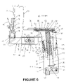
- FIG. 6 is an enlarged, fragmentary, side elevation view of the seat assembly of FIG. 1 .
- FIG. 7 is a cross section view taken substantially along the plane of line 7 — 7 in FIG. 6 .
- FIG. 8 is a top cross sectional view taken substantially along the plane of line 8 — 8 in FIG. 6 .
- FIG. 9 is a top plan view of the armrest assembly of FIG. 6 .
- the seat assembly of the present invention employs a seat mounting assembly which allows the seat to move along an upwardly concaved arcuate path having a center of gravity proximate the center of gravity of the user or person seated on the seat.
- This is broadly known in the prior art, as indicated above and enables the user to periodically adjust the seat position while maintaining the mass of the user center or balanced or in equilibrium on the seat for various arcuate positions.
- the present chair assembly also employs a backrest which is movable about the same center of mass independently of the seat to afford further balanced comfort for extended seat assembly use.
- the chair or seat assembly of the present invention can be seen to include a seat 22 and backrest 23 that are supported by a seat mounting assembly, generally designated 24 .
- Seat mounting assembly 24 can include a conventional vertically adjustable, telescope-type, pedestal 26 which is rollingly supported by a plurality of roller elements 28 mounted to radially extending legs 27 , which elements are conventional and well known in the art. It also should be noted that other supporting structures can be substituted for pedestal 26 .
- the seat assembly of the present invention can be mounted to standard 3 or 4 legged bases, bent tubing base.
- mounting assembly 24 also includes a U-shaped frame 31 mounted on top of pedestal 26 , which frame has upwardly extending frame arms 32 on which armrests 34 are mounted.
- Seat 22 is mounted to a U-shaped cradle 36 positioned inside U-shaped frame 31 and pivoted thereto at pivot mount 37 proximate the upper end of arms 32 .
- Cradle 36 can include a seat mounting plate 38 to which seat 22 can be fastened.
- seat 22 is mounted by cradle 36 for pivoting about an axis 36 proximate the center of mass 39 of a person or user 41 seated on seat 22 .
- the center of mass 39 of user 41 can be seen to remain closely proximate the axis through pivot mount 37 of seat cradle 36 for the full range of postures shown in FIGS. 3–5 .
- mounting assembly 24 further mounts backrest 23 in a near vertical orientation for movement independently of seat 22 along a forwardly concaved arcuate path having a center of curvature which also is proximate the center of mass 39 of the person seated on the seat.
- the center of curvature of the arcuate backrest path is coincident or concentric with the center of curvature 37 for the arcuate seat path.
- mounting assembly 24 of the present invention also includes a U-shaped back support assembly, generally designated 43 , which may include a pair of stub arms 44 having a sleeve 46 secured thereto, for example, by welding, and a U-shaped back strap member 47 with strap ends 48 slidably telescoped inside sleeve 46 .
- stub arm portions 44 of the back support assembly 43 are pivoted at pivotal mount 37 to upper end of frame arms 32 .
- a compression spring 51 having an end which engages a protrusion or tooth 52 on arm stub 44 and an opposite end which is supported by a rotatably mounted cam 53 .
- Axle 54 for the cam is secured for rotation to frame arm 32 , as best may be seen in FIG. 7 .
- Spring 51 therefore, biases back support assembly 43 to essentially the position shown in FIG. 6 , that is, to the point that stub arm 44 engages top member 56 of the U-shaped frame arm.
- backrest 23 and seat 22 which are both independently movable along arcuate paths having centers of curvature proximate the center of mass of the person seated on the chair, can be seen by comparing the postures which can be achieved in FIGS. 3 , 4 and 5 .
- FIG. 3 an erect posture with a downwardly tilting seat and a near vertical backrest is achieved.
- FIG. 4 the seat is pivoted back, while the backrest is also pivoted downwardly.
- FIG. 5 the seat is only partially rearwardly pivoted, while the backrest also is only partially downwardly pivoted.
- center of mass 39 remains in a balanced position proximate the center of pivoting of the seat and backrest.
- the spacing between the seat and backrest varies with each posture for improved comfort.
- backrest support assembly 43 includes an adjustment assembly, generally designated 61 , which is formed for adjustment of the length of the back support assembly between backrest 23 and pivotal mount 37 .
- end 48 of seat support strap 47 can be seen to include a rack structure 62 into which a pair of transversely extending pins 63 can be received.
- Pins 63 are carried by a rotatable knob assembly 64 mounted for rotation to sleeve 46 (see FIG. 8 ). Rotation of knob assembly 64 in a clockwise direction causes the pins to walk along rack 62 and displace strap 47 forwardly toward U-shaped frame 31 .
- Rotation of knob 46 in a counterclockwise direction displaces strap 47 and backrest 23 in a rearward direction as the pins 63 walk along rack 62 .
- a detent in the form of protrusions 65 and a notch 55 can be provided on adjustment assembly 61 .
- the change in the length of back support assembly 43 allows the seat to accommodate users of different sizes with the result that the center of mass 39 for users of different sizes remains proximate the center of pivoting 37 of seat 22 and of backrest 23 .
- the change in radius of curvature of the path of motion of backrest 23 is not accompanied by a change in the relative position of the center of curvature of the seat and the center of curvature of the backrest. Even for users of the same size, adjustment of the radius of curvature of the backrest may produce a comfort level for a particular user which is enhanced and still will result in positioning of the user's center of mass 39 proximate pivot point 37 for all backrest 23 and seat 22 positions.
- change of length assembly 61 can be mounted to seat cradle 36 between pivotal mount 37 and seat mounting plate 38 . This would enable the user to change the radius of rotation of seat 22 .
- Backrest tilt adjustment assembly 71 is coupled between back support assembly 43 and backrest 23 and is formed for manual adjustment of the angle of the backrest relative to backrest support assembly 43 .
- backrest 23 is mounted proximate a lower side thereof by flexible bushings 72 to back support strap 47 .
- Strap 47 also carries a back mounting plate 73 which extends to a position above flexible bushings 72 .
- a back plate 74 of the backrest has a lever plate 76 secured thereto by fasteners 79 .
- a lever 77 is pivotally mounted to plate 76 at pivot point 78 .
- Lever 77 Welded to lever 77 for movement therewith is a wedge member 81 that has a slotted back 86 .
- Lever 77 also carries a latching tooth 82 ( FIGS. 2 and 2 a ) which interengages with a series of teeth 83 provided in a slotted flange 84 of lever plate 76 . (The latching tooth 82 and rack 83 are not shown in FIG. 6 .)
- wedge slot 86 receives a bolt or fastener 87 that is secured to upwardly extending plate 73 carried by back strap 47 .
- the slot 86 is dimensioned for sliding engagement around fastener 87 so that pivoting of lever 77 , as indicated by arrows 88 , about pivot 87 results in upward and downward displacement of wedge member 81 , as indicated by arrows 89 in FIG. 6 .
- armrests 34 also be adjustably mounted to U-shaped frame member 31 .
- armrests 34 can be mounted on plate 91 which fixed to a downwardly depending post 92 that is slidably received in a mating sleeve 93 secured inside arms 32 of the U-shaped frame.
- Vertical adjustment of armrests 34 by sliding a post 92 inside sleeve 93 will not be described in more detail but can be released by lifting lever 95 and locked in place by letting go of the lever, as is well known in the art.
- the horizontal adjustment mechanism 90 armrests 34 can best be understood by reference to FIGS. 6 and 9 .
- a spring 94 is secured at end 96 to hat-shaped plate member 98 at one end and at an opposite end to plate 91 mounted on top of post 92 .
- Spring 94 is a tension spring so that it tends to pull the hat-shaped member in a forward direction, as indicated by arrow 99 relative to plate 91 .
- Mounted on hat-shaped member 98 by fasteners 101 and 102 is armrest cushion assembly 34 .
- Plate 91 is provided with two cutout areas 103 and 104 , which define a plurality rack comprised of teeth 105 dimensioned to receive bolts 106 and 107 therebetween.
- the user can manually grip the armrest 34 and pull it rearwardly against the biasing force 99 to slide hat-shaped member 98 and bolts 106 and 107 in a rearward direction until they clear the teeth 195 and move into the open portion of cutouts 103 and 104 .
- armrest 34 can be laterally adjusted from side-to-side. The user then releases the armrest and spring 94 will bias the armrest forward, causing bolts 106 and 107 to re-engage with teeth 105 and lock the armrest in place. As can be seen in FIG.
- each armrest it is possible to skew each armrest to an angle from a forward direction, either inwardly or outwardly, by seating bolts 106 and 107 in pockets in the cutouts 103 and 104 defined by teeth 105 that are not aligned in a forward direction.
- the armrest adjustment assembly enables lateral shifting of one or both of the armrests as well as angular adjustment of the orientation of each armrest independently.
- chair assembly 21 can be provided with a biasing assembly 110 which biases seat 22 to rotate in a rearward direction.
- biasing can be accomplished by torsion springs 115 mounted in each frame arm between seat cradle 36 and frame arm 32 .
- a biasing adjustment assembly also can be provided, for example, by mounting a cam, such as cam 53 , between leg 120 and the frame arm wall.
- Spring 115 also can be positioned at other radial distances from pivot 37 to vary the movement around the pivot. Biasing of seat 22 rearwardly resists the tendency of the user to slouch or rotate his or her hips forwardly while seated on chair 21 .
- chair assembly 21 can also include a latch or brake assembly, generally designated 111 ( FIGS. 2 and 6 ), which enables the user to selectively lock seat 22 in a desired position against arcuate movement.
- Brake or latching assembly 111 can be provided by a tooth 112 depending down from seat supporting cradle 36 , and a latching or brake rack 113 which has a plurality of pockets 114 dimensioned to receive the tooth 112 .
- Manually engageable handle 116 FIG. 2
- the same handle 116 can be reciprocated vertically in order to adjust the height of the pedestal, as indicated by arrows 118 , which pedestal adjustments are well known in the industry.
- the method of the present invention will be understood to be comprised of the steps of mounting seat 22 for pivoting or rotation about an axis 37 proximate center of gravity 39 ; and mounting backrest 23 for rotation independently of seat 22 about an axis, preferably axis 37 , proximate center of gravity 39 .
Abstract
Description
Claims (20)
Priority Applications (8)
| Application Number | Priority Date | Filing Date | Title |
|---|---|---|---|
| US10/175,452 US7234775B2 (en) | 2002-06-18 | 2002-06-18 | Dynamically balanced seat assembly having independently and arcuately movable seat and backrest and method |
| AU2003261081A AU2003261081A1 (en) | 2002-06-18 | 2003-06-18 | Dynamically balanced seat assembly |
| CA002489399A CA2489399A1 (en) | 2002-06-18 | 2003-06-18 | Dynamically balanced seat assembly |
| CNB038187698A CN100427012C (en) | 2002-06-18 | 2003-06-18 | Dynamically balanced seat assembly |
| PCT/US2003/019591 WO2003105633A1 (en) | 2002-06-18 | 2003-06-18 | Dynamically balanced seat assembly |
| JP2004512551A JP4527529B2 (en) | 2002-06-18 | 2003-06-18 | Dynamically balanced seat assembly |
| GB0500955A GB2406047B (en) | 2002-06-18 | 2003-06-18 | Dynamically balanced seat assembly |
| HK05107996A HK1075374A1 (en) | 2002-06-18 | 2005-09-12 | Dynamically balanced seat assembly |
Applications Claiming Priority (1)
| Application Number | Priority Date | Filing Date | Title |
|---|---|---|---|
| US10/175,452 US7234775B2 (en) | 2002-06-18 | 2002-06-18 | Dynamically balanced seat assembly having independently and arcuately movable seat and backrest and method |
Publications (2)
| Publication Number | Publication Date |
|---|---|
| US20030230918A1 US20030230918A1 (en) | 2003-12-18 |
| US7234775B2 true US7234775B2 (en) | 2007-06-26 |
Family
ID=29733868
Family Applications (1)
| Application Number | Title | Priority Date | Filing Date |
|---|---|---|---|
| US10/175,452 Expired - Lifetime US7234775B2 (en) | 2002-06-18 | 2002-06-18 | Dynamically balanced seat assembly having independently and arcuately movable seat and backrest and method |
Country Status (8)
| Country | Link |
|---|---|
| US (1) | US7234775B2 (en) |
| JP (1) | JP4527529B2 (en) |
| CN (1) | CN100427012C (en) |
| AU (1) | AU2003261081A1 (en) |
| CA (1) | CA2489399A1 (en) |
| GB (1) | GB2406047B (en) |
| HK (1) | HK1075374A1 (en) |
| WO (1) | WO2003105633A1 (en) |
Cited By (32)
| Publication number | Priority date | Publication date | Assignee | Title |
|---|---|---|---|---|
| US20060244294A1 (en) * | 2003-02-18 | 2006-11-02 | Andras Dozsa-Farkas | Chair, especially an office or work chair |
| US20070029857A1 (en) * | 2005-07-14 | 2007-02-08 | Hanson Wayne H | Adjustable motion wheel chair |
| US20070035164A1 (en) * | 2005-08-11 | 2007-02-15 | North Perry C | Adjustable chair station and method of use |
| US20080012412A1 (en) * | 2006-07-11 | 2008-01-17 | Giancarlo Piretti | Chair with seat and backrest with synchronised movement |
| US20080030059A1 (en) * | 2004-06-09 | 2008-02-07 | Kimball International, Inc. | Chair ride mechanism with tension assembly |
| US20090033139A1 (en) * | 2007-08-01 | 2009-02-05 | Hni Technologies Inc. | Adjustable arm rest for chair |
| WO2009048448A1 (en) * | 2006-10-10 | 2009-04-16 | Hector Serber | Dynamically balanced seat assembly |
| US20090236890A1 (en) * | 2006-08-30 | 2009-09-24 | Itoki Corporation | Chair |
| US20110101748A1 (en) * | 2009-10-13 | 2011-05-05 | Goetz Mark W | Ergonomic Adjustable Chair Mechanisms |
| USD637423S1 (en) | 2010-04-13 | 2011-05-10 | Herman Miller, Inc. | Chair |
| USD639091S1 (en) | 2010-04-13 | 2011-06-07 | Herman Miller, Inc. | Backrest |
| US20110266853A1 (en) * | 2010-02-04 | 2011-11-03 | Global Furniture (Zhejiang) Co., Ltd. | Dual use office and leisure chair |
| USD650206S1 (en) | 2010-04-13 | 2011-12-13 | Herman Miller, Inc. | Chair |
| USD652657S1 (en) | 2010-04-13 | 2012-01-24 | Herman Miller, Inc. | Chair |
| USD653061S1 (en) | 2010-04-13 | 2012-01-31 | Herman Miller, Inc. | Chair |
| USD657166S1 (en) | 2010-04-13 | 2012-04-10 | Herman Miller, Inc. | Chair |
| US8449037B2 (en) | 2010-04-13 | 2013-05-28 | Herman Miller, Inc. | Seating structure with a contoured flexible backrest |
| US20130207427A1 (en) * | 2010-10-19 | 2013-08-15 | Okamura Corporation | Chair with armrest |
| US9004597B2 (en) | 2012-09-20 | 2015-04-14 | Steelcase Inc. | Chair back mechanism and control assembly |
| US10021984B2 (en) | 2015-04-13 | 2018-07-17 | Steelcase Inc. | Seating arrangement |
| US10194750B2 (en) | 2015-04-13 | 2019-02-05 | Steelcase Inc. | Seating arrangement |
| US10362874B2 (en) | 2015-07-23 | 2019-07-30 | Herman Miller, Inc. | Seating device |
| US10966527B2 (en) | 2017-06-09 | 2021-04-06 | Steelcase Inc. | Seating arrangement and method of construction |
| US10973332B2 (en) | 2018-02-13 | 2021-04-13 | InkBed, Inc. | Chairs with adjustable back supports |
| US11109683B2 (en) | 2019-02-21 | 2021-09-07 | Steelcase Inc. | Body support assembly and method for the use and assembly thereof |
| US11259637B2 (en) | 2015-04-13 | 2022-03-01 | Steelcase Inc. | Seating arrangement |
| US11304528B2 (en) | 2012-09-20 | 2022-04-19 | Steelcase Inc. | Chair assembly with upholstery covering |
| US11357329B2 (en) | 2019-12-13 | 2022-06-14 | Steelcase Inc. | Body support assembly and methods for the use and assembly thereof |
| US20220232981A1 (en) * | 2019-05-23 | 2022-07-28 | Eavy Medical Instruments (Shanghai) Co. Ltd. | Multi-gear supporting and adjustment mechanism, and adjustable seat |
| US20220378208A1 (en) * | 2019-06-17 | 2022-12-01 | Quali Co., Ltd. | Tilt chair |
| US11559141B2 (en) * | 2019-08-30 | 2023-01-24 | Itoki Corporation | Chair |
| US11596232B2 (en) | 2019-04-16 | 2023-03-07 | MillerKnoll, Inc. | Chair for active engagement of user |
Families Citing this family (26)
| Publication number | Priority date | Publication date | Assignee | Title |
|---|---|---|---|---|
| US20060103221A1 (en) * | 2004-10-08 | 2006-05-18 | Ronald Kleist | Ergonomic chair |
| US8240758B2 (en) * | 2006-03-27 | 2012-08-14 | Nissan North America, Inc. | Deformable seat pan for a tiltable vehicle seat |
| US20080084101A1 (en) * | 2006-10-04 | 2008-04-10 | Mark Powicki | Forward-biased postural chair |
| US8616641B2 (en) | 2006-10-04 | 2013-12-31 | Access Enterprise, Llc | Therapeutic back support and stabilization |
| US10842280B2 (en) * | 2006-10-04 | 2020-11-24 | Access Enterprise, Llc | Therapeutic back support and stabilization |
| DE102006049676B4 (en) * | 2006-10-18 | 2008-12-11 | Sedus Stoll Ag | Chair with tilting seat |
| DE202006016475U1 (en) * | 2006-10-24 | 2007-01-04 | Vitra Patente Ag | Office chair has arm rests which are attached to vertical extensions on sides of shell supporting seat |
| WO2011044379A1 (en) * | 2009-10-07 | 2011-04-14 | Indiana Mills & Manufacturing, Inc. | Apparatus and method for selectively reclining a vehicle seat back |
| WO2014021796A1 (en) * | 2012-08-03 | 2014-02-06 | Kummer Klaus Juergen | Adjustable support structure |
| US8926017B2 (en) * | 2012-09-06 | 2015-01-06 | James E. Grove | Chair with integral pivoting lumbar and seat cushion portions |
| US9458905B2 (en) * | 2012-09-20 | 2016-10-04 | Steelcase Inc. | Spring assembly and method |
| JP6215659B2 (en) * | 2013-11-12 | 2017-10-18 | コクヨ株式会社 | Chair |
| CN106913100A (en) * | 2015-12-28 | 2017-07-04 | 朱政臣 | Seat chassis with inclination and elevation force adjusting device |
| US10463153B2 (en) | 2016-06-09 | 2019-11-05 | Steelcase Inc. | Seating arrangement |
| WO2017221312A1 (en) * | 2016-06-20 | 2017-12-28 | コクヨ株式会社 | Chair and seat support mechanism |
| CN107049626B (en) * | 2016-12-10 | 2018-10-09 | 上海邦邦机器人有限公司 | A kind of chair mechanism and the standing rehabilitation wheelchair vehicle equipped with the chair mechanism |
| DE102017208151A1 (en) * | 2016-10-24 | 2018-04-26 | Stabilus Gmbh | Adjustment device for actuating a brake and mobile unit, in particular chair |
| KR101941528B1 (en) * | 2016-11-15 | 2019-01-23 | 주식회사 다원체어스 | chair with a movable seat |
| CN106724258B (en) * | 2016-12-31 | 2023-12-26 | 恒林家居股份有限公司 | Chair back tilting adjusting mechanism and chair |
| CN106724268B (en) * | 2016-12-31 | 2024-04-09 | 恒林家居股份有限公司 | Chair back front and back position adjusting mechanism and chair |
| CN108056613B (en) * | 2017-01-19 | 2021-04-23 | 安吉县盛信办公家具有限公司 | Waist support seat |
| EP3694377B1 (en) * | 2018-01-09 | 2023-06-07 | Superseating bvba | Seating assembly for improved seating, ergonomic chairs or wheelchairs |
| CN108926171B (en) * | 2018-06-25 | 2021-10-26 | 汇森家具(龙南)有限公司 | Extension type baby family chair capable of being adjusted according to growth of baby body type |
| US10702066B2 (en) * | 2018-11-19 | 2020-07-07 | Profim SP. ZO.O | Office chair |
| JP7469860B2 (en) * | 2019-08-30 | 2024-04-17 | 株式会社イトーキ | Chair |
| CN116370111A (en) * | 2021-11-19 | 2023-07-04 | 康辉医疗科技(苏州)有限公司 | Armrest-adjustable doctor seat |
Citations (29)
| Publication number | Priority date | Publication date | Assignee | Title |
|---|---|---|---|---|
| US4043594A (en) * | 1976-03-12 | 1977-08-23 | Gf Business Equipment, Inc. | Adjustable chair rest member |
| US4589697A (en) * | 1983-09-30 | 1986-05-20 | Fritz Bauer & Sohne Ohg | Bearing device for a chair with incline-adjustable back-rest bearer and incline-adjustable seat |
| US4911501A (en) * | 1989-06-09 | 1990-03-27 | Harter Corporation | Suspension mechanism for connecting chair backs and seats to a pedestal |
| US5009467A (en) * | 1989-05-30 | 1991-04-23 | Mccoy David C | Adjustable armrest for chair |
| US5024484A (en) * | 1986-05-09 | 1991-06-18 | Jurek Buchacz | Adjustable sitting device |
| US5042876A (en) * | 1987-11-10 | 1991-08-27 | Steelcase Inc. | Controller for seating and the like |
| US5244252A (en) | 1990-10-29 | 1993-09-14 | Hector Serber | Seat assembly and method |
| US5261723A (en) * | 1987-12-28 | 1993-11-16 | Isao Hosoe | Ergonomic chair having the seat at a varying position |
| US5308145A (en) * | 1992-02-12 | 1994-05-03 | Kimball International Marketing, Inc. | Reclining chair |
| US5366269A (en) | 1992-08-20 | 1994-11-22 | Life Force Associates, L.P. | Apparatus for restraining a passenger in a vehicle |
| US5437494A (en) | 1992-10-29 | 1995-08-01 | Life Force Associates, L.P. | Rearward moving seat |
| US5558399A (en) | 1994-09-13 | 1996-09-24 | Serber; Hector | Seat and lumbar motion chair, assembly and method |
| US5577802A (en) | 1993-02-22 | 1996-11-26 | Cke Technologies, Inc. | Adjustable chair |
| US5660439A (en) * | 1995-01-04 | 1997-08-26 | Unwalla; Jamshed | Integrated seat and back and mechanisms for chairs |
| US5725276A (en) * | 1995-06-07 | 1998-03-10 | Ginat; Jonathan | Tilt back chair and control |
| US5961073A (en) | 1995-01-11 | 1999-10-05 | The Boeing Company | Reduced head pad seat |
| US5975634A (en) | 1997-10-24 | 1999-11-02 | Steelcase Development Inc. | Chair including novel back construction |
| US6022071A (en) * | 1996-06-10 | 2000-02-08 | Smith; Nathaniel L. | Reclining chair |
| US6030043A (en) * | 1997-12-18 | 2000-02-29 | Bertrand Faure Sitztechnik Gmbh & Co. Kg | Motor vehicle seat, in particular back seat |
| US6099076A (en) * | 1998-03-03 | 2000-08-08 | Steelcase Development Inc. | Chair back construction |
| US6105457A (en) * | 1998-06-10 | 2000-08-22 | Bertrand Faure Sitztechnik Gmbh & Co. Kg | Self-adjusting device that equalizes length |
| US6135554A (en) * | 1998-08-10 | 2000-10-24 | Tsun; Tsai Sung | Recliner chair |
| US20010005094A1 (en) * | 1998-07-27 | 2001-06-28 | Hancock William John | Chair |
| US6334648B1 (en) | 1997-03-21 | 2002-01-01 | Girsberger Holding Ag | Vehicle seat |
| US6523898B1 (en) * | 1999-06-17 | 2003-02-25 | Steelcase Development Corporation | Chair construction |
| US6565155B1 (en) * | 2002-01-22 | 2003-05-20 | Norstar Office Products, Inc. | Chair |
| US6685267B1 (en) * | 2002-12-19 | 2004-02-03 | L & P Property Management Company | Chair and synchrotilt chair mechanism |
| US6705677B2 (en) * | 2000-02-18 | 2004-03-16 | Sugatsun Kogyo Co., Ltd | Chair with seatback and rotating damper device |
| US6709058B1 (en) * | 1999-04-09 | 2004-03-23 | Humanscale Corp. | Ergonomic chair |
Family Cites Families (2)
| Publication number | Priority date | Publication date | Assignee | Title |
|---|---|---|---|---|
| JPH10113251A (en) * | 1996-10-11 | 1998-05-06 | Inaba Seisakusho:Kk | Chair with armrest |
| CA2302063C (en) * | 2000-03-23 | 2010-08-17 | Cke Technologies Inc. | Ergonomic chair |
-
2002
- 2002-06-18 US US10/175,452 patent/US7234775B2/en not_active Expired - Lifetime
-
2003
- 2003-06-18 CA CA002489399A patent/CA2489399A1/en not_active Abandoned
- 2003-06-18 CN CNB038187698A patent/CN100427012C/en not_active Expired - Fee Related
- 2003-06-18 WO PCT/US2003/019591 patent/WO2003105633A1/en active Application Filing
- 2003-06-18 GB GB0500955A patent/GB2406047B/en not_active Expired - Lifetime
- 2003-06-18 AU AU2003261081A patent/AU2003261081A1/en not_active Abandoned
- 2003-06-18 JP JP2004512551A patent/JP4527529B2/en not_active Expired - Lifetime
-
2005
- 2005-09-12 HK HK05107996A patent/HK1075374A1/en not_active IP Right Cessation
Patent Citations (33)
| Publication number | Priority date | Publication date | Assignee | Title |
|---|---|---|---|---|
| US4043594A (en) * | 1976-03-12 | 1977-08-23 | Gf Business Equipment, Inc. | Adjustable chair rest member |
| US4589697A (en) * | 1983-09-30 | 1986-05-20 | Fritz Bauer & Sohne Ohg | Bearing device for a chair with incline-adjustable back-rest bearer and incline-adjustable seat |
| US5024484A (en) * | 1986-05-09 | 1991-06-18 | Jurek Buchacz | Adjustable sitting device |
| US5042876A (en) * | 1987-11-10 | 1991-08-27 | Steelcase Inc. | Controller for seating and the like |
| US5261723A (en) * | 1987-12-28 | 1993-11-16 | Isao Hosoe | Ergonomic chair having the seat at a varying position |
| US5009467A (en) * | 1989-05-30 | 1991-04-23 | Mccoy David C | Adjustable armrest for chair |
| US4911501A (en) * | 1989-06-09 | 1990-03-27 | Harter Corporation | Suspension mechanism for connecting chair backs and seats to a pedestal |
| US5244252A (en) | 1990-10-29 | 1993-09-14 | Hector Serber | Seat assembly and method |
| US5460427A (en) | 1990-10-29 | 1995-10-24 | Serber; Hector | Seat assembly and method |
| US5308145A (en) * | 1992-02-12 | 1994-05-03 | Kimball International Marketing, Inc. | Reclining chair |
| US5366269A (en) | 1992-08-20 | 1994-11-22 | Life Force Associates, L.P. | Apparatus for restraining a passenger in a vehicle |
| US5437494A (en) | 1992-10-29 | 1995-08-01 | Life Force Associates, L.P. | Rearward moving seat |
| US5577802A (en) | 1993-02-22 | 1996-11-26 | Cke Technologies, Inc. | Adjustable chair |
| US5735574A (en) | 1994-09-13 | 1998-04-07 | Serber; Hector | Seat lumbar motion chair, assembly and method |
| US5558399A (en) | 1994-09-13 | 1996-09-24 | Serber; Hector | Seat and lumbar motion chair, assembly and method |
| US5660439A (en) * | 1995-01-04 | 1997-08-26 | Unwalla; Jamshed | Integrated seat and back and mechanisms for chairs |
| US5961073A (en) | 1995-01-11 | 1999-10-05 | The Boeing Company | Reduced head pad seat |
| US5725276A (en) * | 1995-06-07 | 1998-03-10 | Ginat; Jonathan | Tilt back chair and control |
| US6022071A (en) * | 1996-06-10 | 2000-02-08 | Smith; Nathaniel L. | Reclining chair |
| US6334648B1 (en) | 1997-03-21 | 2002-01-01 | Girsberger Holding Ag | Vehicle seat |
| US6086153A (en) | 1997-10-24 | 2000-07-11 | Steelcase Inc. | Chair with reclineable back and adjustable energy mechanism |
| US5979984A (en) | 1997-10-24 | 1999-11-09 | Steelcase Development Inc. | Synchrotilt chair with forwardly movable seat |
| US5975634A (en) | 1997-10-24 | 1999-11-02 | Steelcase Development Inc. | Chair including novel back construction |
| US6030043A (en) * | 1997-12-18 | 2000-02-29 | Bertrand Faure Sitztechnik Gmbh & Co. Kg | Motor vehicle seat, in particular back seat |
| US6099076A (en) * | 1998-03-03 | 2000-08-08 | Steelcase Development Inc. | Chair back construction |
| US6105457A (en) * | 1998-06-10 | 2000-08-22 | Bertrand Faure Sitztechnik Gmbh & Co. Kg | Self-adjusting device that equalizes length |
| US20010005094A1 (en) * | 1998-07-27 | 2001-06-28 | Hancock William John | Chair |
| US6135554A (en) * | 1998-08-10 | 2000-10-24 | Tsun; Tsai Sung | Recliner chair |
| US6709058B1 (en) * | 1999-04-09 | 2004-03-23 | Humanscale Corp. | Ergonomic chair |
| US6523898B1 (en) * | 1999-06-17 | 2003-02-25 | Steelcase Development Corporation | Chair construction |
| US6705677B2 (en) * | 2000-02-18 | 2004-03-16 | Sugatsun Kogyo Co., Ltd | Chair with seatback and rotating damper device |
| US6565155B1 (en) * | 2002-01-22 | 2003-05-20 | Norstar Office Products, Inc. | Chair |
| US6685267B1 (en) * | 2002-12-19 | 2004-02-03 | L & P Property Management Company | Chair and synchrotilt chair mechanism |
Cited By (66)
| Publication number | Priority date | Publication date | Assignee | Title |
|---|---|---|---|---|
| US20060244294A1 (en) * | 2003-02-18 | 2006-11-02 | Andras Dozsa-Farkas | Chair, especially an office or work chair |
| US7484803B2 (en) * | 2003-02-18 | 2009-02-03 | Omp S.R.L | Chair, especially and office or work chair |
| US7625045B2 (en) * | 2004-06-09 | 2009-12-01 | Kimball International, Inc. | Chair ride mechanism with tension assembly |
| US20080030059A1 (en) * | 2004-06-09 | 2008-02-07 | Kimball International, Inc. | Chair ride mechanism with tension assembly |
| US20070029857A1 (en) * | 2005-07-14 | 2007-02-08 | Hanson Wayne H | Adjustable motion wheel chair |
| US7455362B2 (en) * | 2005-07-14 | 2008-11-25 | Kids Up, Inc. | Adjustable motion wheel chair |
| US20070035164A1 (en) * | 2005-08-11 | 2007-02-15 | North Perry C | Adjustable chair station and method of use |
| US20080012412A1 (en) * | 2006-07-11 | 2008-01-17 | Giancarlo Piretti | Chair with seat and backrest with synchronised movement |
| US20090236890A1 (en) * | 2006-08-30 | 2009-09-24 | Itoki Corporation | Chair |
| US7896439B2 (en) * | 2006-08-30 | 2011-03-01 | Itoki Corporation | Chair |
| WO2009048448A1 (en) * | 2006-10-10 | 2009-04-16 | Hector Serber | Dynamically balanced seat assembly |
| US20090033139A1 (en) * | 2007-08-01 | 2009-02-05 | Hni Technologies Inc. | Adjustable arm rest for chair |
| US8016360B2 (en) * | 2007-08-01 | 2011-09-13 | Hni Technologies Inc. | Adjustable arm rest for chair |
| US20110101748A1 (en) * | 2009-10-13 | 2011-05-05 | Goetz Mark W | Ergonomic Adjustable Chair Mechanisms |
| US8944507B2 (en) | 2009-10-13 | 2015-02-03 | Herman Miller, Inc. | Ergonomic adjustable chair mechanisms |
| US20110266853A1 (en) * | 2010-02-04 | 2011-11-03 | Global Furniture (Zhejiang) Co., Ltd. | Dual use office and leisure chair |
| USD639091S1 (en) | 2010-04-13 | 2011-06-07 | Herman Miller, Inc. | Backrest |
| USD637423S1 (en) | 2010-04-13 | 2011-05-10 | Herman Miller, Inc. | Chair |
| USD650206S1 (en) | 2010-04-13 | 2011-12-13 | Herman Miller, Inc. | Chair |
| USD652657S1 (en) | 2010-04-13 | 2012-01-24 | Herman Miller, Inc. | Chair |
| USD653061S1 (en) | 2010-04-13 | 2012-01-31 | Herman Miller, Inc. | Chair |
| USD657166S1 (en) | 2010-04-13 | 2012-04-10 | Herman Miller, Inc. | Chair |
| US8449037B2 (en) | 2010-04-13 | 2013-05-28 | Herman Miller, Inc. | Seating structure with a contoured flexible backrest |
| US9301615B2 (en) | 2010-04-13 | 2016-04-05 | Herman Miller, Inc. | Seating structure with a contoured flexible backrest |
| US20130207427A1 (en) * | 2010-10-19 | 2013-08-15 | Okamura Corporation | Chair with armrest |
| USD742676S1 (en) | 2012-09-20 | 2015-11-10 | Steelcase Inc. | Chair |
| US10206507B2 (en) | 2012-09-20 | 2019-02-19 | Steelcase Inc. | Control assembly for chair |
| US9027998B2 (en) | 2012-09-20 | 2015-05-12 | Steelcase Inc. | Chair assembly |
| US9027999B2 (en) | 2012-09-20 | 2015-05-12 | Steelcase Inc. | Control assembly for chair |
| US9027997B2 (en) | 2012-09-20 | 2015-05-12 | Steelcasel Inc. | Chair assembly |
| US9049935B2 (en) | 2012-09-20 | 2015-06-09 | Steelcase Inc. | Control assembly for chair |
| US9010859B2 (en) | 2012-09-20 | 2015-04-21 | Steelcase Inc. | Chair assembly |
| USD742677S1 (en) | 2012-09-20 | 2015-11-10 | Steelcase Inc. | Chair |
| US9004597B2 (en) | 2012-09-20 | 2015-04-14 | Steelcase Inc. | Chair back mechanism and control assembly |
| US9451826B2 (en) | 2012-09-20 | 2016-09-27 | Steelcase Inc. | Chair assembly |
| US9462888B2 (en) | 2012-09-20 | 2016-10-11 | Steelcase Inc. | Control assembly for chair |
| US9492013B2 (en) | 2012-09-20 | 2016-11-15 | Steelcase Inc. | Chair back mechanism and control assembly |
| US9526339B2 (en) | 2012-09-20 | 2016-12-27 | Steelcase Inc. | Control assembly for chair |
| US9844267B2 (en) | 2012-09-20 | 2017-12-19 | Steelcase Inc. | Chair back mechanism and control assembly |
| US9861201B2 (en) | 2012-09-20 | 2018-01-09 | Steelcase, Inc. | Chair assembly |
| US9918552B2 (en) | 2012-09-20 | 2018-03-20 | Steelcase Inc. | Control assembly for chair |
| US9022476B2 (en) | 2012-09-20 | 2015-05-05 | Steelcase Inc. | Control assembly for chair |
| US11304528B2 (en) | 2012-09-20 | 2022-04-19 | Steelcase Inc. | Chair assembly with upholstery covering |
| US11553797B2 (en) | 2015-04-13 | 2023-01-17 | Steelcase Inc. | Seating arrangement |
| US11963621B2 (en) | 2015-04-13 | 2024-04-23 | Steelcase Inc. | Seating arrangement |
| US10575648B2 (en) | 2015-04-13 | 2020-03-03 | Steelcase Inc. | Seating arrangement |
| US10021984B2 (en) | 2015-04-13 | 2018-07-17 | Steelcase Inc. | Seating arrangement |
| US11324325B2 (en) | 2015-04-13 | 2022-05-10 | Steelcase Inc. | Seating arrangement |
| US11096497B2 (en) | 2015-04-13 | 2021-08-24 | Steelcase Inc. | Seating arrangement |
| US10194750B2 (en) | 2015-04-13 | 2019-02-05 | Steelcase Inc. | Seating arrangement |
| US11259637B2 (en) | 2015-04-13 | 2022-03-01 | Steelcase Inc. | Seating arrangement |
| US10362874B2 (en) | 2015-07-23 | 2019-07-30 | Herman Miller, Inc. | Seating device |
| US11825955B2 (en) | 2017-06-09 | 2023-11-28 | Steelcase Inc. | Seating arrangement and method of construction |
| US10966527B2 (en) | 2017-06-09 | 2021-04-06 | Steelcase Inc. | Seating arrangement and method of construction |
| US10973332B2 (en) | 2018-02-13 | 2021-04-13 | InkBed, Inc. | Chairs with adjustable back supports |
| US11779120B2 (en) | 2018-02-13 | 2023-10-10 | LCL Enterprises, Inc. | Chairs with adjustable back supports |
| US11109683B2 (en) | 2019-02-21 | 2021-09-07 | Steelcase Inc. | Body support assembly and method for the use and assembly thereof |
| US11805905B2 (en) | 2019-04-16 | 2023-11-07 | MillerKnoll, Inc. | Chair for active engagement of user |
| US11596232B2 (en) | 2019-04-16 | 2023-03-07 | MillerKnoll, Inc. | Chair for active engagement of user |
| US20220232981A1 (en) * | 2019-05-23 | 2022-07-28 | Eavy Medical Instruments (Shanghai) Co. Ltd. | Multi-gear supporting and adjustment mechanism, and adjustable seat |
| US11737567B2 (en) * | 2019-05-23 | 2023-08-29 | Eavy Medical Instruments (Shanghai) Co. Ltd. | Multi-gear supporting and adjustment mechanism, and adjustable seat |
| US20220378208A1 (en) * | 2019-06-17 | 2022-12-01 | Quali Co., Ltd. | Tilt chair |
| US11559141B2 (en) * | 2019-08-30 | 2023-01-24 | Itoki Corporation | Chair |
| US11786039B2 (en) | 2019-12-13 | 2023-10-17 | Steelcase Inc. | Body support assembly and methods for the use and assembly thereof |
| US11805913B2 (en) | 2019-12-13 | 2023-11-07 | Steelcase Inc. | Body support assembly and methods for the use and assembly thereof |
| US11357329B2 (en) | 2019-12-13 | 2022-06-14 | Steelcase Inc. | Body support assembly and methods for the use and assembly thereof |
Also Published As
| Publication number | Publication date |
|---|---|
| JP2005529662A (en) | 2005-10-06 |
| CN1688229A (en) | 2005-10-26 |
| GB2406047A (en) | 2005-03-23 |
| GB2406047B (en) | 2005-12-07 |
| AU2003261081A1 (en) | 2003-12-31 |
| GB0500955D0 (en) | 2005-02-23 |
| CA2489399A1 (en) | 2003-12-24 |
| CN100427012C (en) | 2008-10-22 |
| HK1075374A1 (en) | 2005-12-16 |
| US20030230918A1 (en) | 2003-12-18 |
| WO2003105633A1 (en) | 2003-12-24 |
| JP4527529B2 (en) | 2010-08-18 |
Similar Documents
| Publication | Publication Date | Title |
|---|---|---|
| US7234775B2 (en) | Dynamically balanced seat assembly having independently and arcuately movable seat and backrest and method | |
| US8662586B2 (en) | Dynamically balanced seat assembly having independently and arcuately movable backrest and method | |
| US10383445B2 (en) | Dynamically balanced seat assembly having independently and arcuately movable backrest and method | |
| EP0722283B1 (en) | Split back chair | |
| US6969116B2 (en) | Chair with backward and forward passive tilt capabilities | |
| EP0517206B1 (en) | Chair control mechanism | |
| US10743667B2 (en) | Chair back tilt mechanism | |
| US20060284461A1 (en) | Chair with recline control mechanism, recline limit control and back tilt mechanism | |
| US5259663A (en) | Chair seat mounting mechanism | |
| EP1467642B1 (en) | Mobile joint with several stable positions, suitable for use in furniture | |
| JP2003079472A (en) | Rocking chair and its base | |
| US20060082201A1 (en) | Chair | |
| US6325455B1 (en) | Reclining chair | |
| EP0443002A1 (en) | Improved adjustable seating assembly | |
| JP3080585B2 (en) | Chair | |
| JP3998222B2 (en) | Chair support mechanism | |
| JP2001046172A (en) | Chair | |
| EP4335324A1 (en) | Tilt mechanism for a chair | |
| US11717089B2 (en) | Multiple sitting position chair | |
| JPH11113674A (en) | Chair | |
| JP2001046171A (en) | Chair | |
| AU6337890A (en) | Improved adjustable seating assembly | |
| CA2842019A1 (en) | Self-adjustable tilting chair with cantilever mechanism |
Legal Events
| Date | Code | Title | Description |
|---|---|---|---|
| STCF | Information on status: patent grant |
Free format text: PATENTED CASE |
|
| REMI | Maintenance fee reminder mailed | ||
| FPAY | Fee payment |
Year of fee payment: 4 |
|
| SULP | Surcharge for late payment | ||
| FPAY | Fee payment |
Year of fee payment: 8 |
|
| FEPP | Fee payment procedure |
Free format text: MAINTENANCE FEE REMINDER MAILED (ORIGINAL EVENT CODE: REM.); ENTITY STATUS OF PATENT OWNER: SMALL ENTITY |
|
| FEPP | Fee payment procedure |
Free format text: 11.5 YR SURCHARGE- LATE PMT W/IN 6 MO, SMALL ENTITY (ORIGINAL EVENT CODE: M2556); ENTITY STATUS OF PATENT OWNER: SMALL ENTITY |
|
| MAFP | Maintenance fee payment |
Free format text: PAYMENT OF MAINTENANCE FEE, 12TH YR, SMALL ENTITY (ORIGINAL EVENT CODE: M2553); ENTITY STATUS OF PATENT OWNER: SMALL ENTITY Year of fee payment: 12 |