US7240508B2 - Connecting package for refrigerator compressor - Google Patents
Connecting package for refrigerator compressor Download PDFInfo
- Publication number
- US7240508B2 US7240508B2 US11/179,142 US17914205A US7240508B2 US 7240508 B2 US7240508 B2 US 7240508B2 US 17914205 A US17914205 A US 17914205A US 7240508 B2 US7240508 B2 US 7240508B2
- Authority
- US
- United States
- Prior art keywords
- sections
- conductive housing
- cover
- package
- plate
- Prior art date
- Legal status (The legal status is an assumption and is not a legal conclusion. Google has not performed a legal analysis and makes no representation as to the accuracy of the status listed.)
- Expired - Fee Related, expires
Links
Images


Classifications
-
- F—MECHANICAL ENGINEERING; LIGHTING; HEATING; WEAPONS; BLASTING
- F04—POSITIVE - DISPLACEMENT MACHINES FOR LIQUIDS; PUMPS FOR LIQUIDS OR ELASTIC FLUIDS
- F04B—POSITIVE-DISPLACEMENT MACHINES FOR LIQUIDS; PUMPS
- F04B39/00—Component parts, details, or accessories, of pumps or pumping systems specially adapted for elastic fluids, not otherwise provided for in, or of interest apart from, groups F04B25/00 - F04B37/00
-
- H—ELECTRICITY
- H01—ELECTRIC ELEMENTS
- H01H—ELECTRIC SWITCHES; RELAYS; SELECTORS; EMERGENCY PROTECTIVE DEVICES
- H01H61/00—Electrothermal relays
- H01H61/002—Structural combination of a time delay electrothermal relay with an electrothermal protective relay, e.g. a start relay
-
- F—MECHANICAL ENGINEERING; LIGHTING; HEATING; WEAPONS; BLASTING
- F25—REFRIGERATION OR COOLING; COMBINED HEATING AND REFRIGERATION SYSTEMS; HEAT PUMP SYSTEMS; MANUFACTURE OR STORAGE OF ICE; LIQUEFACTION SOLIDIFICATION OF GASES
- F25D—REFRIGERATORS; COLD ROOMS; ICE-BOXES; COOLING OR FREEZING APPARATUS NOT OTHERWISE PROVIDED FOR
- F25D29/00—Arrangement or mounting of control or safety devices
-
- F—MECHANICAL ENGINEERING; LIGHTING; HEATING; WEAPONS; BLASTING
- F25—REFRIGERATION OR COOLING; COMBINED HEATING AND REFRIGERATION SYSTEMS; HEAT PUMP SYSTEMS; MANUFACTURE OR STORAGE OF ICE; LIQUEFACTION SOLIDIFICATION OF GASES
- F25B—REFRIGERATION MACHINES, PLANTS OR SYSTEMS; COMBINED HEATING AND REFRIGERATION SYSTEMS; HEAT PUMP SYSTEMS
- F25B2400/00—General features or devices for refrigeration machines, plants or systems, combined heating and refrigeration systems or heat-pump systems, i.e. not limited to a particular subgroup of F25B
- F25B2400/07—Details of compressors or related parts
- F25B2400/077—Compressor control units, e.g. terminal boxes, mounted on the compressor casing wall containing for example starter, protection switches or connector contacts
Definitions
- the present invention relates generally to a connecting package for a refrigerator compressor, and more particularly to connecting package for a refrigerator compressor, which can be directly mounted on a body of a refrigerator compressor in a state that a motor starter relay element and a low-power motor overload protector are mounted therein.
- a connecting package for a refrigerator compressor is equipped with a PTC (positive temperature coefficient) starter relay element for starting an AC motor used with the refrigerator compressor.
- a PTC starter relay element for starting an AC motor used with the refrigerator compressor.
- an overload protector for protecting a motor from overload and/or a running capacitor (RC) for improving an efficiency of the motor can be provided in the connecting package.
- RC running capacitor
- the connecting package when coupling the connecting package to a circular terminal part provided on the body of the refrigerator compressor from an exterior, moisture including water or rainwater may be easily introduced into a gap formed between the connecting package and the circular terminal part, so that an electrical connection between the connecting package and the circular terminal part becomes unstable.
- the connecting terminal when a connecting terminal protruding out of the connecting package is connected with an external terminal, the connecting terminal may be over-pressed or bent due to external load applied thereto.
- a connecting package for a refrigerator compressor in which an electric connection for various elements is easily achieved through a single package in such a manner that a motor can be protected from overload when an operation of the refrigerator compressor starts while improving an operating efficiency of the motor, moisture including water or rainwater can be prevented from penetrating into a connection part when the connecting package is coupled with the refrigerator compressor while reducing the influence of load generated when coupling the connecting package with the refrigerator compressor, and the connecting package can be stably connected to a body of the refrigerator compressor, thereby stably operating the refrigerator compressor.
- the present invention is directed to a connecting package for a refrigerator compressor that substantially obviates one or more problems due to limitations and disadvantages of the related art.
- a connecting package for a refrigerator compressor comprising: a base including an overload protector mounting section and a motor starter relay element mounting section and having first to third pin connecting ports connected to a compressor motor through a circular terminal of a compressor body; a cover detachably coupled to an upper portion of the base, including a dome-shaped overload protector mounting section and a dome-shaped motor starter relay element mounting section corresponding to the overload protector mounting section and the motor starter relay element mounting section of the base, and having a plurality of slots for connecting terminals formed around the dome-shaped overload protector mounting section and the dome-shaped motor starter relay element mounting section; a motor starter relay element mounted in the motor starter relay element mounting sections of the base and the cover and having first and second pin connectors positioned corresponding to the first and second pin connecting ports of the base; and a low-power overload protector mounted in the overload protector mounting sections of the base and the cover and having a first connecting terminal connected
- the cover is provided at both sides thereof with a downward extension section having a coupling protrusion
- the base is formed at both sides thereof with a coupling slot detachably coupled with the coupling protrusion of the cover such that the base is detachably coupled to the cover.
- protective guides are aligned around the slots of the cover so as to protect the connecting terminals protruding through the slots.
- a circular terminal shielding cover is formed at a lower portion of the base in order to protect the circular terminal formed on the body of the refrigerator compressor when the connecting package is connected to the circular terminal formed on the body of the refrigerator compressor.
- a downward extension section is integrally formed with an outer surface of the cover so as to detachably couple the connecting package to the compressor body.
- one of the first and second pin connectors of the motor starter relay element and another pin connector connected to the first connecting terminal of the overload protector are connected to a main winding section of a motor
- the other one of the first and second pin connectors of the motor starter relay element is connected to an auxiliary winding section of the motor
- one of the first and second pin connectors connected to the main winding section of the motor is provided with a connecting terminal connected to an external power source through the slots formed in the cover.
- the low-power overload protector includes a conductive housing can having a bottom section, lateral sections, a flange extending from the lateral sections and a connecting terminal extending from one end of the conductive housing can; a bimetal member having a first end fixed to the bottom section of the conductive housing can and a second end provided with a movable contact; an insulation gasket having a wing cover surrounding the flange of the conductive housing can and an opening window which is a moving path for the bimetal member; a plate having first and second sections separated from each other and including a fixing contact, a connecting terminal provided at one end of the plate, and clamp wings provided at both sides of the plate in order to fix the flange of the conductive housing can and the wing cover of the insulation gasket together; and a coil heater having first and second ends fixed to first and second sections of the plate, respectively, serving as the heating element.
- the low-power overload protector includes a conductive housing can having a bottom section, lateral sections, a flange extending from the lateral sections and a connecting terminal extending from one end of the conductive housing can; a bimetal member having a first end fixed to the bottom section of the conductive housing can and a second end provided with a movable contact; an insulation gasket having a wing cover surrounding the flange of the conductive housing can and an opening window which is a moving path for the bimetal member; a plate having first and second sections separated from each other and including first and second protruded ledge sections provided in the first and second sections while forming a central hole therebetween, a fixing contact, a connecting terminal provided at one end of the plate, and clamp wings provided at both sides of the plate in order to fix the flange of the conductive housing can and the wing cover of the insulation gasket together; a ceramic plate heater element accommodated in a recess defined by the first and second ledge sections, serving
- FIG. 1 a is a perspective view of a connecting package for a refrigerator compressor according to one embodiment of the present invention.
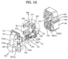
- FIG. 1 b is an exploded perspective view of a connecting package for a refrigerator compressor shown in FIG. 1 a.
- FIGS. 1 c and 1 d are perspective and plan views of a connecting package shown in FIG. 1 b , in which a motor starter relay element, an overload protector and connecting terminals are installed in a base.
- FIG. 1 e is a bottom view of a base shown in FIG. 1 d.
- FIG. 2 a is a perspective view of a connecting package for a refrigerator compressor according to another embodiment of the present invention.
- FIG. 2 b is an exploded perspective view of a connecting package shown in FIG. 2 a.
- FIG. 2 c is a perspective view of a connecting package for a refrigerator compressor shown in FIG. 2 a when it is viewed from a base.
- FIG. 3 a is a perspective view of a coil heater type overload protector mounted in a connecting package for a refrigerator compressor according to one embodiment of the present invention.
- FIG. 3 b is an exploded perspective view of a coil heater type overload protector shown in FIG. 3 a.
- FIG. 4 a is an exploded perspective view of a ceramic heater type overload protector mounted in a connecting package for a refrigerator compressor according to another embodiment of the present invention.
- FIG. 4 b is an exploded perspective view of a ceramic heater type overload protector shown in FIG. 4 a.
- FIGS. 5 a and 5 b are perspective views illustrating a quick connector and a pin connector connected to connecting terminals of an overload protector shown in FIG. 3 a or 4 a according to one embodiment of the present invention.
- FIGS. 6 a to 6 c are views illustrating structures of a quick connector and a pin connector according to the position of a connecting terminal of an overload protector, and a structure of a receiving section of a base for the quick connector and the pin connector corresponding to the structures of the quick connector and the pin connector.
- FIG. 7 is a perspective view illustrating of a connecting package, in which a detachable clamp is additionally installed on the connecting package in order to fix the connecting package to a body of a refrigerator compressor.
- FIG. 1 a is a perspective view of a connecting package 100 A for a refrigerator compressor according to one embodiment of the present invention
- FIG. 1 b is an exploded perspective view of the connecting package 100 A shown in FIG. 1 a
- FIGS. 1 c and 1 d are perspective and plan views of the connecting package 100 A shown in FIG. 1 b , in which a motor starter relay element, an overload protector and connecting terminals are installed on a base
- FIG. 1 e is a bottom view of the base shown in FIG. 1 d.
- the connecting package 100 A for the refrigerator compressor includes a base 100 having first to third pin connecting ports PC 1 to PC 3 connected to a compressor motor through a circular terminal (not shown) provided on a compressor body, a cover 200 detachably coupled to an upper portion of the base 100 , a motor starter relay element 300 having first and second pin connectors 325 and 335 positioned corresponding to the first and second pin connecting ports PC 1 and PC 2 of the base 100 and a PTC (positive temperature coefficient) starter element 310 , and a low-power overload protector 400 having a heating element for shortening a reaction time of the low-power overload protector 400 .
- the base 100 includes an overload protector mounting section 140 for mounting the overload protector 400 and a motor starter relay element mounting section 130 .
- the base 100 has receiving sections 100 QC and 100 PC for receiving a quick connector QC and a pin connector PC connected to both connecting terminals of the overload protector 400 .
- a coupling slot 150 b is formed at both sides of the base 100 for allowing the base 100 to be coupled to the cover 200 .
- the coupling slot 150 b is defined by a recess 150 formed at both sides of the base 100 and a support bar 150 a connecting both sidewalls of the recess 150 .
- a coupling protrusion 250 a formed at an end of a downward extension portion 250 of the cover 200 is inserted into the coupling slot 150 b so that the base 100 is coupled to the cover 200 .
- the cover 200 is provided with a dome-shaped overload protector mounting section 270 b and a dome-shaped motor starter relay element mounting section 270 a corresponding to the overload protector mounting section 140 and the motor starter relay element mounting section 130 of the base 100 .
- a plurality of slots 221 , 223 , 231 , 233 and 200 QC for connecting terminals are formed around the dome-shaped overload protector mounting section 270 b and the dome-shaped motor starter relay element mounting section 270 a.
- the motor starter relay element 300 and the overload protector 400 are installed in the motor starter relay element mounting sections 130 and 270 a and the overload protector mounting sections 140 and 270 b of the base 100 and the cover 200 when the base 100 is coupled to the cover 200 .
- the motor starter relay element 300 is provided to start an operation of a motor and includes a disc-shaped PTC starter element 310 installed at the recess formed at a center of the base 100 , rectangular conductive plates 320 and 330 provided at both sides of the disc-shaped PTC starter element 310 in opposition to each other, and an elastic connecting member 340 having a U-shape. A free end of the elastic connecting member 340 elastically makes contact with the disc-shaped PTC starter element 310 and a closed end of the elastic connecting member 340 is fixed to the rectangular conductive plates 320 and 330 such that the rectangular conductive plates 320 and 330 are electrically connected to the disc-shaped PTC starter element 310 .
- the rectangular conductive plates 320 and 330 are provided with pin connectors 325 and 335 , which are connected to a main winding section and an auxiliary winding section of the motor in parallel to each other, respectively.
- the pin connectors 325 and 335 are connected to a running capacitor (not shown) through a jumper.
- the rectangular conductive plates 320 and 330 include connecting terminals 321 , 323 , 331 , and 333 for allowing the rectangular conductive plates 320 and 330 to be connected to external devices.
- At least two ribs 140 a are formed on one inner wall of the overload protector mounting section 140 of the base 100 so as to protect the overload protector 400 from a vibration or heat (refer to FIG. 1 b and FIG. 1 c ).
- ribs 130 a are formed on an inner wall of the motor starter relay element mounting section 130 of the base 100 outwards in a radial direction of a PTC starter element 310 of the motor starter relay element 300 so as to support the PTC starter element 310 with the ribs 130 a facing each other (refer to FIG. 1 c ).
- Each of the first and second pin connectors 325 and 335 has a pin receptacle 325 a and 335 a for detachably fixing a corresponding pin to the pin receptacle 325 a and 335 a (refer to FIG. 1 c and FIG. 1 d ).
- the overload protector 400 mounted in the connecting package for the refrigerator compressor of the present invention is a low-power overload protector, in which a heater is accommodated.
- the heater When overload is applied to the overload protector 400 , the heater generates heat so that a temperature of the overload protector 400 rapidly reaches an operational temperature thereof, thereby reducing power consumption and achieving reliability and stability of the overload protector 400 .
- the connecting package according to the present invention may employ various overload protectors.
- One of such overload protectors is a coil heater type overload protector as shown in FIGS. 3 a and 3 b.
- the low-power overload protector 400 shown in FIGS. 3 a and 3 b includes a conductive housing can 410 having a bottom section, lateral sections, a flange 413 extending from the lateral sections and a connecting terminal 415 extending from one end of the conductive housing can 410 , a bimetal member 420 having a first end fixed to the bottom section of the conductive housing can 410 and a second end provided with a movable contact, an insulation gasket 430 having a wing cover 430 b surrounding the flange 413 of the conductive housing can 410 and an opening window 430 a which is a moving path for the bimetal member 420 , a plate 450 having first and second sections 453 a and 453 b separated from each other about a space section 451 and including a fixing contact 445 , a connecting terminal 455 provided at one end of the plate 450 , and clamp wings 453 a ′ and 453 b ′ provided at both sides of the plate 450 in order to
- the connecting terminal 455 provided at one end of the plate 450 , the coil heater 440 connected between the first and second sections 453 a and 453 b of the plate 450 , the fixing contact 445 of the plate 450 , the bimetal member 420 , and the connecting terminal 415 of the conductive housing can 410 are electrically connected through a circuit.
- the coil heater 440 When overload is applied, the coil heater 440 generates heat so that a reaction time of the bimetal member 420 can be shortened.
- the bimetal member 420 is snap-operated so that the bimetal member 420 is separated from the fixing contact.
- the circuit connection for the above elements is disconnected, so that power being supplied to the circuit can be shut off.
- the plate 450 includes a dome-shaped receiving cavity 454 for receiving the coil heater 440 .
- the connecting package of the present invention may employ an overload protector different from the above coil heater type overload protector.
- the connecting package of the present invention can employ an overload protector disclosed in U.S. patent application Ser. No. 10/727,297 entitled “low-power motor overload protector” and a continuation application thereof.
- FIGS. 4 a and 4 b The above low-power overload protector is shown in FIGS. 4 a and 4 b with reference numeral 400 ′.
- the low-power overload protector 400 ′ includes a conductive housing can 410 having a bottom section, lateral sections, a flange 413 extending from the lateral sections, and a connecting terminal 415 extending from one end of the conductive housing can 410 , a bimetal member 420 having a first end fixed to the bottom section of the conductive housing can 410 and a second end provided with a movable contact, an insulation gasket 430 having a wing cover 430 b surrounding the flange 413 of the conductive housing can 410 and an opening window 430 a which is a moving path for the bimetal member 420 , a plate 450 ′ having first and second sections 453 a and 453 b separated from each other about a space section 451 and including first and second protruded ledge sections 454 a and 454 b provided in the first and second sections 453 a and 453 b while forming a central hole 454 c
- the connecting terminal 455 provided at one end of the plate 450 ′, the ceramic plate heater element 460 connected between first and second ledge sections 454 a and 454 b of the plate 450 ′, the fixing contact 445 of the plate 450 ′, the bimetal member 420 , and the connecting terminal 415 of the conductive housing can 410 are electrically connected through a circuit.
- the heating film 465 c of the ceramic plate heater element 460 generates heat so that a reaction time of the bimetal member 420 can be shortened.
- the bimetal member 420 is snap-operated so that the bimetal member 420 is separated from the fixing contact.
- the circuit connection for the above elements is disconnected, so that power being supplied to the circuit can be shut off.
- the pin connector PC positioned corresponding to the third pin connecting port PC 3 of the base 100 and the quick connector QC connected to an external power source are connected to both connecting terminals 425 and 455 of the above overload protectors 400 and 400 ′, respectively.
- FIGS. 5 a and 5 b Structures of the quick connector QC and the pin connector PC are shown in FIGS. 5 a and 5 b.
- the quick connector QC includes a fixing section 10 Q fixed to the connecting terminal (for example, the connecting terminal 455 ) of the overload protector, a downward extension section 20 Q, a quick terminal 30 Q, and a connecting section 25 Q for connecting the downward extension section 20 Q to a lower portion of the quick terminal 30 Q.
- the pin connector PC includes a fixing section 10 P fixed to the connecting terminal (for example, the connecting terminal 415 ) of the overload protector, a downward extension section 20 P, and a pin terminal 30 P.
- Such pin connector and the quick connector are connected to the connecting terminals of the overload protector, so structures of the pin connector and the quick connector may vary depending on the position of the overload protector and the direction of the connecting terminals. If the structures of the pin connector and the quick connector are changed, the receiving section of the base for the pin connector and the quick connector is also changed corresponding to the structures of the pin connector and the quick connector.
- FIGS. 6 a to 6 c shows structures of the quick connector and the pin connector according to the position of the connecting terminal of the overload protector, and the structure of the receiving section of the base for the quick connector and the pin connector corresponding to the structures of the quick connector and the pin connector.
- a pin connector PC′ includes a fixing section 10 PC′ fixed to the connecting terminal (for example, the connecting terminal 415 ) of the overload protector, a horizontal extension section 20 PC′, and a pin terminal 30 PC′.
- the pin connector PC′ is substantially identical to the pin connector PC shown in FIG. 5 b except for the horizontal extension section 20 PC′.
- a quick connector QC′ includes a fixing section 10 QC′ fixed to the connecting terminal (for example, the connecting terminal 455 ) of the overload protector, a horizontal extension section 20 QC′, and a quick terminal 30 QC′.
- the quick connector QC′ is substantially identical to the quick connector QC shown in FIG. 5 a except for the horizontal extension section 20 QC′, which may act as the connecting section 25 Q of the quick connector shown in FIG. 5 a.
- a structure of a receiving section of a base 100 ′′ for receiving the pin connector PC′ and the quick connector QC′ must be changed corresponding to the structures of the pin connector PC′ and the quick connector QC′.
- a connecting package 100 B is substantially identical to the connecting package 100 A shown in FIG. 1 a to 1 e , except for structures of the cover and the base.
- a cover 200 ′ of the connecting package 100 B further includes protective guides for protecting connecting terminals 321 , 323 , 331 and 333 protruding through slots 221 , 231 , 233 and 200 QC so that the slots 221 , 231 , 233 and 200 QC are protected by means of slot protecting channels 221 ′, 231 ′, 233 ′ and 200 QC′.
- the base 100 ′ of the connecting package 100 B further includes a circular terminal shielding cover 170 formed at a lower portion of the base 100 ′ in order to protect the circular terminal when the connecting package 100 B is connected to the circular terminal provided on the body of the refrigerator compressor.
- a flange 100 ′ a is formed on an outer side of an upper edge of the base 100 ′ so as to ensure a water injection insulation or keep foreign substances from entering the connecting package 100 B (refer to FIG. 2 a and FIG. 2 b ).
- the base 100 or 100 ′ of the connecting package 100 A or 100 B can be assembled with the cover 200 or 200 ′ of the connecting package 100 A or 100 B.
- the cover 200 ′ or the base 100 ′ of the connecting package 100 B shown in FIGS. 2 a to 2 c can be used for the connecting package 100 A shown in FIGS. 1 a to 1 e.
- a detachable clamp can be additionally provided on an outer surface of the connecting package 100 A or 100 B of the present invention. That is, the detachable clamp is provided on an outer surface of the cover so as to detachably couple the connecting package for the refrigerator compressor to a coupling section of the body of the refrigerator compressor, for example, to a vertical wall fence having a hole.
- Such a detachable clamp 500 includes a rim member disposed around an assembly of the base 100 and the cover 200 ′ and downward extension sections 510 a and 510 b provided at both ends of the rim member.
- the downward extension sections 510 a and 510 b are provided at end portions thereof with coupling protrusions 510 a ′ and 510 b ′ so as to allow the detachable clamp 500 to be coupled with the coupling section of the compressor body. That is, the coupling protrusions 510 a ′ and 510 b ′ are inserted into the hole of the vertical wall fence.
- the detachable clamp 500 can be further provided at an end of the rim member with a shielding roof, which shields an external connecting terminal slot when the detachable clamp 500 is coupled with the connecting package, thereby preventing moisture from penetrating into the external connecting terminal slot.
- an earlobe 290 can be provided at an outer surface of the cover as a stopper for limiting the movement of the detachable clamp 500 .
- the covers and the bases according to various embodiments of the present invention can be assembled with each other in use.
- the connecting package for the refrigerator compressor of the present invention an electric connection for various elements is easily achieved through one package in such a manner that a motor can be protected from overload when an operation of the refrigerator compressor starts while improving an operating efficiency of the motor, moisture including water or rainwater can be prevented from penetrating into a connection part when the connecting package is coupled with the refrigerator compressor while reducing an influence of load generated when coupling the connecting package with the refrigerator compressor, and the connecting package can be stably connected to the body of the refrigerator compressor, thereby stably operating the refrigerator compressor.
Abstract
Description
Claims (28)
Applications Claiming Priority (2)
| Application Number | Priority Date | Filing Date | Title |
|---|---|---|---|
| KR1020040093421A KR100698762B1 (en) | 2004-11-16 | 2004-11-16 | Connecting package for refrigerator compressor |
| KR10-2004-0093421 | 2004-11-16 |
Publications (2)
| Publication Number | Publication Date |
|---|---|
| US20060101841A1 US20060101841A1 (en) | 2006-05-18 |
| US7240508B2 true US7240508B2 (en) | 2007-07-10 |
Family
ID=35636813
Family Applications (1)
| Application Number | Title | Priority Date | Filing Date |
|---|---|---|---|
| US11/179,142 Expired - Fee Related US7240508B2 (en) | 2004-11-16 | 2005-07-12 | Connecting package for refrigerator compressor |
Country Status (6)
| Country | Link |
|---|---|
| US (1) | US7240508B2 (en) |
| EP (1) | EP1657733B1 (en) |
| JP (1) | JP4116636B2 (en) |
| KR (1) | KR100698762B1 (en) |
| CN (2) | CN2852462Y (en) |
| DE (1) | DE602005003911T2 (en) |
Cited By (6)
| Publication number | Priority date | Publication date | Assignee | Title |
|---|---|---|---|---|
| US20060202657A1 (en) * | 2005-03-10 | 2006-09-14 | Electrica S.R.L. | Voltmeter relay with improved terminal coupling |
| US20060205248A1 (en) * | 2005-03-10 | 2006-09-14 | Electrica S.R.L. | Voltmeter relay with shaped base which contains slots designed to form seatings for the insertion of "faston" connectors |
| US20070133149A1 (en) * | 2003-11-07 | 2007-06-14 | Koninklijke Phillips Electronics N.V. | Starter housing for gas discharge lamp, and method of mounting same |
| US20110110001A1 (en) * | 2008-04-14 | 2011-05-12 | Gabriel Porto Neto | Motor overload protecting device, motor start device, backup protecting element and process for obtaining a backup protecting element |
| US20120327539A1 (en) * | 2011-06-23 | 2012-12-27 | Keith Washburn | Assembly of electric motor starter components |
| US10502202B1 (en) * | 2018-05-22 | 2019-12-10 | Whirlpool, S.A. | Cooling compressor comprising protection arrangement for electrical connections |
Families Citing this family (11)
| Publication number | Priority date | Publication date | Assignee | Title |
|---|---|---|---|---|
| US20070044499A1 (en) * | 2005-08-25 | 2007-03-01 | Reilly John H Jr | Cooling system repair kit |
| CN101330236B (en) * | 2007-06-20 | 2012-06-13 | 乐金电子(天津)电器有限公司 | Connection structure for overload protection terminal shell of motor stator |
| ITVA20070081A1 (en) | 2007-10-22 | 2009-04-23 | B D G El S P A | ASSEMBLY OF ELECTRICAL CONNECTION, STARTING AND PROTECTION OF AN ELECTRIC MOTORCYCLE COMPRESSOR IN HERMETIC METAL SHELL |
| CN101764382A (en) * | 2008-12-25 | 2010-06-30 | 乐金电子(天津)电器有限公司 | Electric source connecting box of compressor |
| US8174354B2 (en) * | 2010-07-23 | 2012-05-08 | Sensata Technologies Massachusetts, Inc. | Method and apparatus for control of failed thermistor devices |
| CN102377055B (en) * | 2010-08-10 | 2013-08-21 | 上海合璧电子电器有限公司 | Improved structure of connector base |
| KR101870897B1 (en) * | 2011-10-17 | 2018-06-26 | 삼성전자주식회사 | Refrigerator and integrated relay module of compressor for the same |
| CN104066215B (en) * | 2014-05-08 | 2016-01-13 | 博太科防爆设备(上海)有限公司 | A kind of self-limiting heating cable with explosion-proof link circuit and preparation method thereof |
| DE102015211417A1 (en) * | 2015-06-22 | 2016-12-22 | Robert Bosch Gmbh | Plug with improved manufacturability by injection molding |
| WO2017010830A1 (en) | 2015-07-14 | 2017-01-19 | 주식회사 비티케이 | Overload protection device for compressor motor |
| KR101710679B1 (en) * | 2015-07-14 | 2017-02-28 | (주)비티케이 | Protecter |
Citations (7)
| Publication number | Priority date | Publication date | Assignee | Title |
|---|---|---|---|---|
| US4646824A (en) * | 1985-12-23 | 1987-03-03 | Texaco Inc. | Patterns of horizontal and vertical wells for improving oil recovery efficiency |
| US4701824A (en) * | 1985-03-15 | 1987-10-20 | Texas Instruments Incorporated | Protected refrigerator compressor motor systems and motor protectors therefor |
| US4862306A (en) * | 1988-12-22 | 1989-08-29 | Texas Instruments Incorporated | Combination motor protector and starter apparatus |
| US5170307A (en) | 1991-05-31 | 1992-12-08 | Texas Instruments Incorporated | Mounting apparatus for electrical motor control components |
| US6317304B1 (en) | 1996-11-13 | 2001-11-13 | Texas Instrumentos Electronicos Do Brasil Ltda. | Assembly of electric motor-controlling components |
| US6548924B2 (en) | 2000-06-06 | 2003-04-15 | Texas Instruments Incorporated | Protective device for a hermetically sealed type compressor and a hermetically sealed compressor listing same |
| US6795283B2 (en) | 2001-04-20 | 2004-09-21 | Texas Instruments Incorporated | Electricals package integrating run capacitor, motor protector and motor starter |
Family Cites Families (9)
| Publication number | Priority date | Publication date | Assignee | Title |
|---|---|---|---|---|
| GB1252928A (en) * | 1968-02-20 | 1971-11-10 | ||
| DE2604764C3 (en) * | 1976-02-07 | 1978-08-03 | Danfoss A/S, Nordborg (Daenemark) | Electrical connection device for an encapsulated refrigeration machine |
| US4476452A (en) * | 1982-09-27 | 1984-10-09 | Texas Instruments Incorporated | Motor protector |
| US4499517A (en) * | 1983-11-14 | 1985-02-12 | Texas Instruments Incorporated | Motor protector particularly suited for use with compressor motors |
| US5729416A (en) * | 1995-05-30 | 1998-03-17 | General Electric Company | Motor starter and protector module |
| US5903418A (en) * | 1998-02-24 | 1999-05-11 | Texas Instruments Incorporated | Overcurrent protection apparatus for refrigeration and conditioning compressor systems |
| EP1111316A1 (en) * | 1999-12-20 | 2001-06-27 | MINU S.p.A. | Terminal block assembly for connecting motor-actuated compressors, particularly for refrigerators |
| KR100494009B1 (en) * | 2003-03-25 | 2005-06-10 | 자화전자 주식회사 | Combination joining package for refrigerator compressor |
| KR100503970B1 (en) * | 2004-04-14 | 2005-07-26 | 자화전자 주식회사 | A unification module of motor starter and protector |
-
2004
- 2004-11-16 KR KR1020040093421A patent/KR100698762B1/en not_active IP Right Cessation
-
2005
- 2005-07-12 US US11/179,142 patent/US7240508B2/en not_active Expired - Fee Related
- 2005-07-26 JP JP2005216011A patent/JP4116636B2/en not_active Expired - Fee Related
- 2005-07-27 DE DE602005003911T patent/DE602005003911T2/en active Active
- 2005-07-27 EP EP05106895A patent/EP1657733B1/en not_active Expired - Fee Related
- 2005-08-03 CN CNU2005201128687U patent/CN2852462Y/en not_active Expired - Lifetime
- 2005-08-03 CN CNA200510091021XA patent/CN1776970A/en active Pending
Patent Citations (7)
| Publication number | Priority date | Publication date | Assignee | Title |
|---|---|---|---|---|
| US4701824A (en) * | 1985-03-15 | 1987-10-20 | Texas Instruments Incorporated | Protected refrigerator compressor motor systems and motor protectors therefor |
| US4646824A (en) * | 1985-12-23 | 1987-03-03 | Texaco Inc. | Patterns of horizontal and vertical wells for improving oil recovery efficiency |
| US4862306A (en) * | 1988-12-22 | 1989-08-29 | Texas Instruments Incorporated | Combination motor protector and starter apparatus |
| US5170307A (en) | 1991-05-31 | 1992-12-08 | Texas Instruments Incorporated | Mounting apparatus for electrical motor control components |
| US6317304B1 (en) | 1996-11-13 | 2001-11-13 | Texas Instrumentos Electronicos Do Brasil Ltda. | Assembly of electric motor-controlling components |
| US6548924B2 (en) | 2000-06-06 | 2003-04-15 | Texas Instruments Incorporated | Protective device for a hermetically sealed type compressor and a hermetically sealed compressor listing same |
| US6795283B2 (en) | 2001-04-20 | 2004-09-21 | Texas Instruments Incorporated | Electricals package integrating run capacitor, motor protector and motor starter |
Cited By (9)
| Publication number | Priority date | Publication date | Assignee | Title |
|---|---|---|---|---|
| US20070133149A1 (en) * | 2003-11-07 | 2007-06-14 | Koninklijke Phillips Electronics N.V. | Starter housing for gas discharge lamp, and method of mounting same |
| US7618290B2 (en) * | 2003-11-07 | 2009-11-17 | Koninklijke Philips Electronics N.V. | Starter housing for gas discharge lamp, and method of mounting same |
| US20060202657A1 (en) * | 2005-03-10 | 2006-09-14 | Electrica S.R.L. | Voltmeter relay with improved terminal coupling |
| US20060205248A1 (en) * | 2005-03-10 | 2006-09-14 | Electrica S.R.L. | Voltmeter relay with shaped base which contains slots designed to form seatings for the insertion of "faston" connectors |
| US20110110001A1 (en) * | 2008-04-14 | 2011-05-12 | Gabriel Porto Neto | Motor overload protecting device, motor start device, backup protecting element and process for obtaining a backup protecting element |
| US20120327539A1 (en) * | 2011-06-23 | 2012-12-27 | Keith Washburn | Assembly of electric motor starter components |
| JP2013009585A (en) * | 2011-06-23 | 2013-01-10 | Sensata Technologies Massachusetts Inc | Assembly of electric motor starter components |
| US9025286B2 (en) * | 2011-06-23 | 2015-05-05 | Sensata Technologies Massachusetts, Inc. | Assembly of electric motor starter components |
| US10502202B1 (en) * | 2018-05-22 | 2019-12-10 | Whirlpool, S.A. | Cooling compressor comprising protection arrangement for electrical connections |
Also Published As
| Publication number | Publication date |
|---|---|
| EP1657733B1 (en) | 2007-12-19 |
| EP1657733A1 (en) | 2006-05-17 |
| US20060101841A1 (en) | 2006-05-18 |
| CN2852462Y (en) | 2006-12-27 |
| KR20060054743A (en) | 2006-05-23 |
| JP4116636B2 (en) | 2008-07-09 |
| JP2006147529A (en) | 2006-06-08 |
| KR100698762B1 (en) | 2007-03-23 |
| DE602005003911T2 (en) | 2008-12-04 |
| CN1776970A (en) | 2006-05-24 |
| DE602005003911D1 (en) | 2008-01-31 |
Similar Documents
| Publication | Publication Date | Title |
|---|---|---|
| US7240508B2 (en) | Connecting package for refrigerator compressor | |
| EP0676786B1 (en) | Compact protector | |
| US5145417A (en) | Terminal block assembly for hermetic terminal structure | |
| US10790652B2 (en) | Operation device | |
| WO2006080698A1 (en) | Clamp device for mounting connecting package for refrigerator compressor | |
| KR20050021306A (en) | A motor start relay and an electric compressor using same | |
| KR101935283B1 (en) | Inverter assembly for electromotive compressor | |
| US5035653A (en) | Terminal block for a hermetic terminal assembly | |
| WO2006080695A1 (en) | Connecting package for refrigerator compressor | |
| US10790651B2 (en) | Operation device | |
| KR100894666B1 (en) | Electricals package integrating run capacitor, motor protector and motor starter | |
| KR200382927Y1 (en) | A Terminal Assembly For Hermatic Compressor | |
| KR100328321B1 (en) | Feeder for use in compressor | |
| CN211093884U (en) | Motor, water knockout drum and dish washer that has this water knockout drum | |
| KR200264453Y1 (en) | Connecting package for refrigerator compressor capable of detachably mounting running capacitor and motor protector | |
| CN216591849U (en) | Electric stove | |
| KR100494009B1 (en) | Combination joining package for refrigerator compressor | |
| KR200260155Y1 (en) | Connecting package for refrigerator compressor | |
| KR200206163Y1 (en) | Integral package case for starting relay and overload protector | |
| CN111294992B (en) | Heater assembly | |
| JPH0658260A (en) | Closed type motor-driven compressor | |
| JP3526534B2 (en) | Power supply device for compressor | |
| JP2000161221A (en) | Connector for compressor | |
| KR20040040828A (en) | Cluster block of overload protector for compressor | |
| JP2005304141A (en) | Electric connection box |
Legal Events
| Date | Code | Title | Description |
|---|---|---|---|
| AS | Assignment |
Owner name: TEXAS INSTRUMENTS INCORPORATED, TEXAS Free format text: ASSIGNMENT OF ASSIGNORS INTEREST;ASSIGNOR:PARK, YOUNG-HWAN;REEL/FRAME:016779/0305 Effective date: 20050629 |
|
| AS | Assignment |
Owner name: MORGAN STANLEY & CO. INCORPORATED, NEW YORK Free format text: SECURITY AGREEMENT;ASSIGNORS:SENSATA TECHNOLOGIES, INC.;SENSATA TECHNOLOGIES FINANCE COMPANY, LLC;REEL/FRAME:017575/0533 Effective date: 20060427 |
|
| AS | Assignment |
Owner name: SENSATA TECHNOLOGIES, INC., MASSACHUSETTS Free format text: ASSIGNMENT OF ASSIGNORS INTEREST;ASSIGNOR:TEXAS INSTRUMENTS INCORPORATED;REEL/FRAME:017870/0147 Effective date: 20060427 |
|
| STCF | Information on status: patent grant |
Free format text: PATENTED CASE |
|
| AS | Assignment |
Owner name: SENSATA TECHNOLOGIES MASSACHUSETTS, INC., MASSACHU Free format text: ASSIGNMENT OF ASSIGNORS INTEREST;ASSIGNOR:SENSATA TECHNOLOGIES, INC.;REEL/FRAME:021018/0690 Effective date: 20080430 |
|
| AS | Assignment |
Owner name: MORGAN STANLEY & CO. INCORPORATED, NEW YORK Free format text: SECURITY AGREEMENT;ASSIGNOR:SENSATA TECHNOLOGIES MASSACHUSETTS, INC.;REEL/FRAME:021450/0563 Effective date: 20080430 |
|
| FPAY | Fee payment |
Year of fee payment: 4 |
|
| AS | Assignment |
Owner name: SENSATA TECHNOLOGIES MASSACHUSETTS, INC., MASSACHU Free format text: RELEASE BY SECURED PARTY;ASSIGNOR:MORGAN STANLEY & CO. INCORPORATED;REEL/FRAME:026293/0352 Effective date: 20110512 Owner name: SENSATA TECHNOLOGIES, INC., MASSACHUSETTS Free format text: RELEASE BY SECURED PARTY;ASSIGNOR:MORGAN STANLEY & CO. INCORPORATED;REEL/FRAME:026293/0352 Effective date: 20110512 Owner name: SENSATA TECHNOLOGIES FINANCE COMPANY, LLC, MASSACH Free format text: RELEASE BY SECURED PARTY;ASSIGNOR:MORGAN STANLEY & CO. INCORPORATED;REEL/FRAME:026293/0352 Effective date: 20110512 |
|
| FPAY | Fee payment |
Year of fee payment: 8 |
|
| FEPP | Fee payment procedure |
Free format text: MAINTENANCE FEE REMINDER MAILED (ORIGINAL EVENT CODE: REM.); ENTITY STATUS OF PATENT OWNER: LARGE ENTITY |
|
| LAPS | Lapse for failure to pay maintenance fees |
Free format text: PATENT EXPIRED FOR FAILURE TO PAY MAINTENANCE FEES (ORIGINAL EVENT CODE: EXP.); ENTITY STATUS OF PATENT OWNER: LARGE ENTITY |
|
| STCH | Information on status: patent discontinuation |
Free format text: PATENT EXPIRED DUE TO NONPAYMENT OF MAINTENANCE FEES UNDER 37 CFR 1.362 |
|
| FP | Lapsed due to failure to pay maintenance fee |
Effective date: 20190710 |