US7279367B1 - Method of manufacturing a thyristor semiconductor device - Google Patents
Method of manufacturing a thyristor semiconductor device Download PDFInfo
- Publication number
- US7279367B1 US7279367B1 US11/007,510 US751004A US7279367B1 US 7279367 B1 US7279367 B1 US 7279367B1 US 751004 A US751004 A US 751004A US 7279367 B1 US7279367 B1 US 7279367B1
- Authority
- US
- United States
- Prior art keywords
- silicon
- layer
- forming
- emitter
- anode
- Prior art date
- Legal status (The legal status is an assumption and is not a legal conclusion. Google has not performed a legal analysis and makes no representation as to the accuracy of the status listed.)
- Expired - Fee Related, expires
Links
- 239000004065 semiconductor Substances 0.000 title claims abstract description 98
- 238000004519 manufacturing process Methods 0.000 title description 15
- 239000007943 implant Substances 0.000 claims abstract description 123
- 239000000463 material Substances 0.000 claims abstract description 76
- 238000000034 method Methods 0.000 claims abstract description 76
- FVBUAEGBCNSCDD-UHFFFAOYSA-N silicide(4-) Chemical compound [Si-4] FVBUAEGBCNSCDD-UHFFFAOYSA-N 0.000 claims abstract description 67
- 229910021332 silicide Inorganic materials 0.000 claims abstract description 59
- 238000012545 processing Methods 0.000 claims abstract description 26
- 230000002093 peripheral effect Effects 0.000 claims abstract description 16
- XUIMIQQOPSSXEZ-UHFFFAOYSA-N Silicon Chemical compound [Si] XUIMIQQOPSSXEZ-UHFFFAOYSA-N 0.000 claims description 99
- 229910052710 silicon Inorganic materials 0.000 claims description 94
- 239000010703 silicon Substances 0.000 claims description 91
- 125000006850 spacer group Chemical group 0.000 claims description 45
- 239000002019 doping agent Substances 0.000 claims description 35
- 229910052751 metal Inorganic materials 0.000 claims description 26
- 239000002184 metal Substances 0.000 claims description 25
- 238000000059 patterning Methods 0.000 claims description 24
- 230000015572 biosynthetic process Effects 0.000 claims description 21
- 238000002955 isolation Methods 0.000 claims description 18
- 239000011810 insulating material Substances 0.000 claims description 10
- 239000012212 insulator Substances 0.000 claims description 8
- 229910021420 polycrystalline silicon Inorganic materials 0.000 claims description 8
- 229920005591 polysilicon Polymers 0.000 claims description 7
- 238000009792 diffusion process Methods 0.000 claims description 5
- 238000005530 etching Methods 0.000 claims description 5
- 150000004767 nitrides Chemical class 0.000 claims description 5
- 230000001154 acute effect Effects 0.000 claims description 3
- 239000003870 refractory metal Substances 0.000 claims description 3
- 150000002500 ions Chemical class 0.000 claims description 2
- 239000002245 particle Substances 0.000 claims 1
- 230000000149 penetrating effect Effects 0.000 claims 1
- 229920001296 polysiloxane Polymers 0.000 claims 1
- 239000012535 impurity Substances 0.000 abstract description 27
- 230000000903 blocking effect Effects 0.000 abstract description 17
- 239000010410 layer Substances 0.000 description 63
- 239000000758 substrate Substances 0.000 description 49
- 229920002120 photoresistant polymer Polymers 0.000 description 33
- 238000005755 formation reaction Methods 0.000 description 18
- 230000008569 process Effects 0.000 description 11
- 239000003989 dielectric material Substances 0.000 description 8
- 125000005843 halogen group Chemical group 0.000 description 6
- 238000000151 deposition Methods 0.000 description 5
- 230000008021 deposition Effects 0.000 description 5
- PXHVJJICTQNCMI-UHFFFAOYSA-N Nickel Chemical compound [Ni] PXHVJJICTQNCMI-UHFFFAOYSA-N 0.000 description 4
- 229910052785 arsenic Inorganic materials 0.000 description 4
- RQNWIZPPADIBDY-UHFFFAOYSA-N arsenic atom Chemical compound [As] RQNWIZPPADIBDY-UHFFFAOYSA-N 0.000 description 4
- 230000000873 masking effect Effects 0.000 description 4
- BASFCYQUMIYNBI-UHFFFAOYSA-N platinum Chemical compound [Pt] BASFCYQUMIYNBI-UHFFFAOYSA-N 0.000 description 4
- ZOXJGFHDIHLPTG-UHFFFAOYSA-N Boron Chemical compound [B] ZOXJGFHDIHLPTG-UHFFFAOYSA-N 0.000 description 3
- 229910052796 boron Inorganic materials 0.000 description 3
- 239000003990 capacitor Substances 0.000 description 3
- 230000000694 effects Effects 0.000 description 3
- 229910052732 germanium Inorganic materials 0.000 description 3
- 230000010354 integration Effects 0.000 description 3
- 229910000577 Silicon-germanium Inorganic materials 0.000 description 2
- RTAQQCXQSZGOHL-UHFFFAOYSA-N Titanium Chemical compound [Ti] RTAQQCXQSZGOHL-UHFFFAOYSA-N 0.000 description 2
- 239000002253 acid Substances 0.000 description 2
- 230000008901 benefit Effects 0.000 description 2
- 230000015556 catabolic process Effects 0.000 description 2
- 229910017052 cobalt Inorganic materials 0.000 description 2
- 239000010941 cobalt Substances 0.000 description 2
- GUTLYIVDDKVIGB-UHFFFAOYSA-N cobalt atom Chemical compound [Co] GUTLYIVDDKVIGB-UHFFFAOYSA-N 0.000 description 2
- GNPVGFCGXDBREM-UHFFFAOYSA-N germanium atom Chemical compound [Ge] GNPVGFCGXDBREM-UHFFFAOYSA-N 0.000 description 2
- BHEPBYXIRTUNPN-UHFFFAOYSA-N hydridophosphorus(.) (triplet) Chemical compound [PH] BHEPBYXIRTUNPN-UHFFFAOYSA-N 0.000 description 2
- 239000011261 inert gas Substances 0.000 description 2
- 229910052759 nickel Inorganic materials 0.000 description 2
- 229910052697 platinum Inorganic materials 0.000 description 2
- 229910052719 titanium Inorganic materials 0.000 description 2
- 239000010936 titanium Substances 0.000 description 2
- WFKWXMTUELFFGS-UHFFFAOYSA-N tungsten Chemical compound [W] WFKWXMTUELFFGS-UHFFFAOYSA-N 0.000 description 2
- 229910052721 tungsten Inorganic materials 0.000 description 2
- 239000010937 tungsten Substances 0.000 description 2
- OKTJSMMVPCPJKN-UHFFFAOYSA-N Carbon Chemical compound [C] OKTJSMMVPCPJKN-UHFFFAOYSA-N 0.000 description 1
- BOTDANWDWHJENH-UHFFFAOYSA-N Tetraethyl orthosilicate Chemical compound CCO[Si](OCC)(OCC)OCC BOTDANWDWHJENH-UHFFFAOYSA-N 0.000 description 1
- 238000013459 approach Methods 0.000 description 1
- 125000004429 atom Chemical group 0.000 description 1
- 239000005380 borophosphosilicate glass Substances 0.000 description 1
- 229910052799 carbon Inorganic materials 0.000 description 1
- 239000000969 carrier Substances 0.000 description 1
- 230000008859 change Effects 0.000 description 1
- 238000006243 chemical reaction Methods 0.000 description 1
- 239000004020 conductor Substances 0.000 description 1
- 238000006731 degradation reaction Methods 0.000 description 1
- 230000000779 depleting effect Effects 0.000 description 1
- 238000011161 development Methods 0.000 description 1
- 230000018109 developmental process Effects 0.000 description 1
- 238000010586 diagram Methods 0.000 description 1
- 230000009977 dual effect Effects 0.000 description 1
- 230000005684 electric field Effects 0.000 description 1
- 230000003028 elevating effect Effects 0.000 description 1
- 238000005516 engineering process Methods 0.000 description 1
- 230000005669 field effect Effects 0.000 description 1
- 239000011521 glass Substances 0.000 description 1
- 238000010438 heat treatment Methods 0.000 description 1
- 238000011065 in-situ storage Methods 0.000 description 1
- 238000002347 injection Methods 0.000 description 1
- 239000007924 injection Substances 0.000 description 1
- 238000010849 ion bombardment Methods 0.000 description 1
- 230000007246 mechanism Effects 0.000 description 1
- 229910044991 metal oxide Inorganic materials 0.000 description 1
- 150000004706 metal oxides Chemical class 0.000 description 1
- 238000012986 modification Methods 0.000 description 1
- 230000004048 modification Effects 0.000 description 1
- 229910052757 nitrogen Inorganic materials 0.000 description 1
- 230000003647 oxidation Effects 0.000 description 1
- 238000007254 oxidation reaction Methods 0.000 description 1
- 230000003071 parasitic effect Effects 0.000 description 1
- 229910052698 phosphorus Inorganic materials 0.000 description 1
- 238000007517 polishing process Methods 0.000 description 1
- 239000002210 silicon-based material Substances 0.000 description 1
- 239000007858 starting material Substances 0.000 description 1
- 239000000126 substance Substances 0.000 description 1
- 238000006467 substitution reaction Methods 0.000 description 1
- 239000002344 surface layer Substances 0.000 description 1
- 238000012876 topography Methods 0.000 description 1
Images


Classifications
-
- H—ELECTRICITY
- H01—ELECTRIC ELEMENTS
- H01L—SEMICONDUCTOR DEVICES NOT COVERED BY CLASS H10
- H01L21/00—Processes or apparatus adapted for the manufacture or treatment of semiconductor or solid state devices or of parts thereof
- H01L21/70—Manufacture or treatment of devices consisting of a plurality of solid state components formed in or on a common substrate or of parts thereof; Manufacture of integrated circuit devices or of parts thereof
- H01L21/77—Manufacture or treatment of devices consisting of a plurality of solid state components or integrated circuits formed in, or on, a common substrate
- H01L21/78—Manufacture or treatment of devices consisting of a plurality of solid state components or integrated circuits formed in, or on, a common substrate with subsequent division of the substrate into plural individual devices
- H01L21/82—Manufacture or treatment of devices consisting of a plurality of solid state components or integrated circuits formed in, or on, a common substrate with subsequent division of the substrate into plural individual devices to produce devices, e.g. integrated circuits, each consisting of a plurality of components
- H01L21/84—Manufacture or treatment of devices consisting of a plurality of solid state components or integrated circuits formed in, or on, a common substrate with subsequent division of the substrate into plural individual devices to produce devices, e.g. integrated circuits, each consisting of a plurality of components the substrate being other than a semiconductor body, e.g. being an insulating body
-
- H—ELECTRICITY
- H01—ELECTRIC ELEMENTS
- H01L—SEMICONDUCTOR DEVICES NOT COVERED BY CLASS H10
- H01L21/00—Processes or apparatus adapted for the manufacture or treatment of semiconductor or solid state devices or of parts thereof
- H01L21/70—Manufacture or treatment of devices consisting of a plurality of solid state components formed in or on a common substrate or of parts thereof; Manufacture of integrated circuit devices or of parts thereof
- H01L21/77—Manufacture or treatment of devices consisting of a plurality of solid state components or integrated circuits formed in, or on, a common substrate
- H01L21/78—Manufacture or treatment of devices consisting of a plurality of solid state components or integrated circuits formed in, or on, a common substrate with subsequent division of the substrate into plural individual devices
- H01L21/82—Manufacture or treatment of devices consisting of a plurality of solid state components or integrated circuits formed in, or on, a common substrate with subsequent division of the substrate into plural individual devices to produce devices, e.g. integrated circuits, each consisting of a plurality of components
- H01L21/822—Manufacture or treatment of devices consisting of a plurality of solid state components or integrated circuits formed in, or on, a common substrate with subsequent division of the substrate into plural individual devices to produce devices, e.g. integrated circuits, each consisting of a plurality of components the substrate being a semiconductor, using silicon technology
- H01L21/8232—Field-effect technology
- H01L21/8234—MIS technology, i.e. integration processes of field effect transistors of the conductor-insulator-semiconductor type
- H01L21/8238—Complementary field-effect transistors, e.g. CMOS
- H01L21/823814—Complementary field-effect transistors, e.g. CMOS with a particular manufacturing method of the source or drain structures, e.g. specific source or drain implants or silicided source or drain structures or raised source or drain structures
-
- H—ELECTRICITY
- H01—ELECTRIC ELEMENTS
- H01L—SEMICONDUCTOR DEVICES NOT COVERED BY CLASS H10
- H01L21/00—Processes or apparatus adapted for the manufacture or treatment of semiconductor or solid state devices or of parts thereof
- H01L21/70—Manufacture or treatment of devices consisting of a plurality of solid state components formed in or on a common substrate or of parts thereof; Manufacture of integrated circuit devices or of parts thereof
- H01L21/77—Manufacture or treatment of devices consisting of a plurality of solid state components or integrated circuits formed in, or on, a common substrate
- H01L21/78—Manufacture or treatment of devices consisting of a plurality of solid state components or integrated circuits formed in, or on, a common substrate with subsequent division of the substrate into plural individual devices
- H01L21/82—Manufacture or treatment of devices consisting of a plurality of solid state components or integrated circuits formed in, or on, a common substrate with subsequent division of the substrate into plural individual devices to produce devices, e.g. integrated circuits, each consisting of a plurality of components
- H01L21/822—Manufacture or treatment of devices consisting of a plurality of solid state components or integrated circuits formed in, or on, a common substrate with subsequent division of the substrate into plural individual devices to produce devices, e.g. integrated circuits, each consisting of a plurality of components the substrate being a semiconductor, using silicon technology
- H01L21/8232—Field-effect technology
- H01L21/8234—MIS technology, i.e. integration processes of field effect transistors of the conductor-insulator-semiconductor type
- H01L21/8238—Complementary field-effect transistors, e.g. CMOS
- H01L21/823828—Complementary field-effect transistors, e.g. CMOS with a particular manufacturing method of the gate conductors, e.g. particular materials, shapes
- H01L21/823835—Complementary field-effect transistors, e.g. CMOS with a particular manufacturing method of the gate conductors, e.g. particular materials, shapes silicided or salicided gate conductors
-
- H—ELECTRICITY
- H01—ELECTRIC ELEMENTS
- H01L—SEMICONDUCTOR DEVICES NOT COVERED BY CLASS H10
- H01L27/00—Devices consisting of a plurality of semiconductor or other solid-state components formed in or on a common substrate
- H01L27/02—Devices consisting of a plurality of semiconductor or other solid-state components formed in or on a common substrate including semiconductor components specially adapted for rectifying, oscillating, amplifying or switching and having at least one potential-jump barrier or surface barrier; including integrated passive circuit elements with at least one potential-jump barrier or surface barrier
- H01L27/04—Devices consisting of a plurality of semiconductor or other solid-state components formed in or on a common substrate including semiconductor components specially adapted for rectifying, oscillating, amplifying or switching and having at least one potential-jump barrier or surface barrier; including integrated passive circuit elements with at least one potential-jump barrier or surface barrier the substrate being a semiconductor body
- H01L27/10—Devices consisting of a plurality of semiconductor or other solid-state components formed in or on a common substrate including semiconductor components specially adapted for rectifying, oscillating, amplifying or switching and having at least one potential-jump barrier or surface barrier; including integrated passive circuit elements with at least one potential-jump barrier or surface barrier the substrate being a semiconductor body including a plurality of individual components in a repetitive configuration
- H01L27/102—Devices consisting of a plurality of semiconductor or other solid-state components formed in or on a common substrate including semiconductor components specially adapted for rectifying, oscillating, amplifying or switching and having at least one potential-jump barrier or surface barrier; including integrated passive circuit elements with at least one potential-jump barrier or surface barrier the substrate being a semiconductor body including a plurality of individual components in a repetitive configuration including bipolar components
- H01L27/1027—Thyristors
-
- H—ELECTRICITY
- H01—ELECTRIC ELEMENTS
- H01L—SEMICONDUCTOR DEVICES NOT COVERED BY CLASS H10
- H01L27/00—Devices consisting of a plurality of semiconductor or other solid-state components formed in or on a common substrate
- H01L27/02—Devices consisting of a plurality of semiconductor or other solid-state components formed in or on a common substrate including semiconductor components specially adapted for rectifying, oscillating, amplifying or switching and having at least one potential-jump barrier or surface barrier; including integrated passive circuit elements with at least one potential-jump barrier or surface barrier
- H01L27/12—Devices consisting of a plurality of semiconductor or other solid-state components formed in or on a common substrate including semiconductor components specially adapted for rectifying, oscillating, amplifying or switching and having at least one potential-jump barrier or surface barrier; including integrated passive circuit elements with at least one potential-jump barrier or surface barrier the substrate being other than a semiconductor body, e.g. an insulating body
- H01L27/1203—Devices consisting of a plurality of semiconductor or other solid-state components formed in or on a common substrate including semiconductor components specially adapted for rectifying, oscillating, amplifying or switching and having at least one potential-jump barrier or surface barrier; including integrated passive circuit elements with at least one potential-jump barrier or surface barrier the substrate being other than a semiconductor body, e.g. an insulating body the substrate comprising an insulating body on a semiconductor body, e.g. SOI
-
- H—ELECTRICITY
- H01—ELECTRIC ELEMENTS
- H01L—SEMICONDUCTOR DEVICES NOT COVERED BY CLASS H10
- H01L29/00—Semiconductor devices adapted for rectifying, amplifying, oscillating or switching, or capacitors or resistors with at least one potential-jump barrier or surface barrier, e.g. PN junction depletion layer or carrier concentration layer; Details of semiconductor bodies or of electrodes thereof ; Multistep manufacturing processes therefor
- H01L29/66—Types of semiconductor device ; Multistep manufacturing processes therefor
- H01L29/66007—Multistep manufacturing processes
- H01L29/66075—Multistep manufacturing processes of devices having semiconductor bodies comprising group 14 or group 13/15 materials
- H01L29/66227—Multistep manufacturing processes of devices having semiconductor bodies comprising group 14 or group 13/15 materials the devices being controllable only by the electric current supplied or the electric potential applied, to an electrode which does not carry the current to be rectified, amplified or switched, e.g. three-terminal devices
- H01L29/66363—Thyristors
- H01L29/66371—Thyristors structurally associated with another device, e.g. built-in diode
- H01L29/66378—Thyristors structurally associated with another device, e.g. built-in diode the other device being a controlling field-effect device
Definitions
- the present disclosure is related to semiconductor devices and their methods of manufacture; and, more particularly, to the devices and manufacture of metal oxide semiconductors and thyristors.
- SOI Silicon On Insulator
- MOSFETs formed on conventional Silicon-on-insulators exhibit lower parasitic junction capacitance, greater on/off isolation and better sub-threshold swing in comparison to their equivalent bulk counterparts. With these performance advantages, the SOI devices can perform with lower power, higher speed and improved switching characteristics.
- the silicide, epitaxial deposition and implant processes might each be performed using separate patterning provisions. They may be patterned for placing silicide and/or epitaxial material offset from the source/drain extension regions. By such offset, manufacturing tolerances may be accommodated during their fabrication such that the silicide and/or epitaxial material might not overlap the extension regions. Accordingly, it may be noted that an overall length of a MOSFET could thus be limited by the manufacturing tolerances of the various mask patternings associated with the separate silicide, epi and/or implant masks.
- TCCT thin capacitively coupled thyristor
- an electrode over one of the base regions might need to be formed with an offset relative to its other base region.
- Such offset may allow operation of the electrode with reduced likelihood of gate induced leakage (GIDL) effects relative to the offset base region.
- GIDL gate induced leakage
- fabrication of the offset base might require separate masking provisions to assure its offset relationship relative to the gate electrode.
- silicide patterning might also use its own masking provisions for forming the silicide with clearance from the electrode and the base regions. For if the salicide were to overlap two thyristor regions, the shorting by the silicide could destroy thyristor operation.
- these separate patterning and masked provisions for the source/drain extensions, silicide and/or epi structures for a MOSFET may each add to the complexity, cost and size of the overall device.
- the separate mask provisions for definition of the offset base, the emitter silicide and/or the epi structures for the thin capacitively coupled thyristor may similarly add to its overall complexity, cost and size.
- the formation of a capacitively coupled thyristor may similarly use a common mask for defining a base region silicide, epitaxial structure and/or leakage implant.
- a shallow implant extension region may be formed in a layer of semiconductor material in contiguous relationship with a deep level implant region.
- the interface therebetween may define an outline that is related to the peripheral edge as defined for the silicide.
- a transistor comprises source and drain regions of first conductivity type with a channel of second conductivity type between the source and drain regions.
- a gate electrode may be disposed over the channel region and operable under bias to affect an electric field in the channel region.
- At least one source and drain extension region of first conductivity type may extends laterally between the source/drain region and the channel region.
- the source/drain region may comprise dopant of the first conductivity type and may be contiguous with its respective extension region. In particular embodiments, the source/drain region may be more heavily doped than the extension region.
- the source/drain region may be offset laterally from the outline of the gate electrode and the silicide thereover may comprise a peripheral edge that is laterally offset from a boundary between the source/drain region and the extension region.
- a peripheral edge of the silicide meets a surface of the source/drain region and a spacer might also be formed against a sidewall of the gate electrode to serve as a silicide-blocking layer.
- Such silicide-blocking layer may be disposed with a lateral extent over the extension region.
- a method of processing a semiconductor device may comprise patterning a silicide-blocking layer over semiconductor material. After implanting a select region of the semiconductor material, a metal may be formed over exposed regions of the semiconductor material and a portion of the metal diffused into a surface layer of the semiconductor material as defined by the patterned silicide-blocking layer.
- the implanting may comprise a first implant to place first impurities into a first region of the semiconductor material and to define a thyristor base region in accordance with patterning of the silicide-blocking layer.
- the implanting might also comprise a second implant to place second impurities into a second region of the semiconductor material to define an emitter region of the thyristor next to the base region.
- the extent of the first region may be defined by the patterned salicide-blocking layer and at least one of the implant energy, implant angle, and species of implant associated with the first impurities.
- the second region may be defined by the patterned salicide-blocking layer and at least one of the implant energy, implant angle and species associated with the second impurities implant. At least one of the implant energy, implant angle and species of the second impurity implant may differ from that of the first impurities implant. This may result in the implant or implants being self aligned to the salicide blocking material.
- the implant for the first impurities may comprise an angled implant to implant regions of semiconductor material beneath a portion of the patterned salicide blocking layer. Additionally, a substantially orthogonal implant may be used for the second impurities implant.
- the first region of the first implant species may be defined to extend laterally in the layer of semiconductor material to a position beneath the salicide blocking layer but laterally clear of the region beneath the outline of the gate electrode.
- a semiconductor device may comprise a layer of semiconductor material with a plurality of regions of alternating first and second opposite conductivity-types disposed therein.
- One region of the plurality of regions comprises an anode-emitter and another region may comprise a cathode-emitter.
- the cathode-emitter may comprise an N-type conductivity and the anode-emitter may comprise a P-type conductivity.
- At least two regions of the plurality of regions may be disposed between the anode-emitter and the cathode-emitter.
- the anode-emitter may define a junction where it meets one of the at least two regions.
- a first electrode may be disposed over at least one of the regions between the anode and the cathode-emitters.
- Epitaxial material may be disposed over one of the cathode-emitter and/or anode-emitter regions and may be offset laterally clear of the junction of the anode and/or cathode-emitter region(s) at the surface of the layer of semiconductor material.
- the anode-emitter, the cathode-emitter, and the at least two different regions of alternating regions therebetween define a thyristor having a surface region thereof that is free of silicide between a peripheral edge of the epitaxial material over the anode-emitter and a peripheral edge of the first electrode.
- the silicide free surface may further overlap a full-width of the first base region and the second base region.
- the semiconductor device may comprise conductive material to propagate a reference voltage to at least one of the anode and cathode-emitters.
- a memory device may comprise a thyristor formed in a layer of semiconductor material.
- the thyristor may comprise an anode-emitter, a cathode-emitter, and first and second base regions between the anode-emitter and the cathode-emitter.
- a first electrode may be disposed over and capacitively coupled to at least a portion of the first base region.
- the second base region may be offset laterally clear of the first electrode.
- a raised provision of semiconductor material may be disposed on the layer of semiconductor material and at least one of the anode and cathode-emitters.
- the raised portion of the anode-emitter may comprise an outline spaced laterally clear from the first base region.
- a method of forming a thyristor memory device may comprise forming a wordline over a layer of silicon.
- a conformal layer of silicide blocking material may be formed over the wordline and the layer of silicon and patterned to define a salicide mask comprising a first part over at least a portion of the wordline, a second part contiguous with the first part and conformal to a sidewall of the wordline, and a third part contiguous with the second part as a shoulder that extends outwardly from the wordline and across a portion of the layer of silicon that neighbors the wordline.
- Dopant of a second type conductivity may be implanted into select regions of the silicon using an acute angle of incidence to penetrate peripheral regions beneath the salicide mask. After the implanting with the second type conductivity dopant, first type conductivity dopant may be implanted in the layer of silicon using a substantially orthogonal angle of incidence to penetrate regions self-aligned with the salicide mask.
- FIG. 1 is a cross-sectional view of a portion of a semiconductor view device during a method of fabrication according to an embodiment of the present invention, showing two separate electrodes over different active regions of the semiconductor substrate.
- FIG. 2 is a cross-sectional view of a portion of the semiconductor substrate of FIG. 1 in another stage of processing, useful to further describe a method of fabricating the semiconductor device and showing deep level source/drain implants about a gate electrode.
- FIG. 3 is a cross sectional view of a portion of the semiconductor substrate of FIGS. 1 through 2 , in another stage of processing and useful to further describe the method of forming the semiconductor device in an embodiment of the present invention, and showing implants about a gate electrode associated with another active region.
- FIG. 4 is a cross sectional view of the portion of the semiconductor device of FIGS. 1 through 3 , in another stage of processing and useful to further describe the method of forming a semiconductor device in accordance with an embodiment of the present invention, and showing the silicide in exposed regions of silicon as defined by a silicide blocking mask.
- FIG. 5 is a cross sectional view of a portion of a semiconductor device and useful to further describe an alternative method of processing of the present invention, and showing extension regions about a gate electrode of an access transistor to a thyristor memory.
- FIG. 6 is a cross sectional view of a portion of a semiconductor device of FIG. 5 , in another stage of processing a thin capacitively coupled thyristor and showing implants for at least one of the N-base and one of the anode/cathode-emitters.
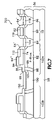
- FIG. 7 is a cross sectional view of a portion of a semiconductor substrate of FIGS. 6 and 7 in another stage of processing useful to further describe a method of forming a thyristor memory, and showing salicide formed over exposed silicon regions.
- FIG. 9 is a cross sectional view of a portion of a semiconductor substrate illustrating a thyristor memory comprising gate electrodes recessed within trenches of an SOI substrate.
- FIG. 11 is a cross sectional view showing a portion of a semiconductor substrate during another method of processing a thyristor memory, and showing leakage implants overlapping an interface between an anode-emitter and base region.
- FIGS. 13A through 13B are cross sectional views showing a portion of a semiconductor substrate in two different stages of processing useful to describe a method of fabricating a thyristor memory in accordance with an alternative embodiment of the present invention, and showing a sacrificial element to define patterning of base region and to affect alignment of impurity lifetime adjustment species.
- N-type MOS transistor the dopant type(s) of the substrate in addition to the doped regions thereof may be reversed to form a P-type MOS device.
- both N-type and P-type devices may be formed on the same substrate as part of a combined CMOS process.
- a method of processing a semiconductor device may comprise forming first and second active regions 22 , 24 in semiconductor substrate 10 .
- An isolation trench 12 may be formed to define a boundary between the first and second active region(s).
- the semiconductor substrate 10 may initially comprise a P-type semiconductor material 21 and the first active region 22 may be defined by implanting N-type dopant for well 20 within the semiconductor material of substrate 10 .
- the patterning and definition of the “N” well for the first active region 22 may be performed using standard photolithographic patterning techniques.
- a dielectric such as an oxide may be formed over substrate 10 and may be described as a gate oxide for different gate stacks that may be formed thereover.
- dielectric 16 A, 16 B poly may then be deposited, doped and patterned in to define gate electrodes 14 A, 14 B in insulated relationship over respective active regions 22 , 24 .
- one of the first or second active region(s) 22 , 24 may be masked with photoresist while processing the other active region for defining devices therein.
- active region 22 may be masked while pattering N-type, extension regions 30 , 32 about gate electrode 14 B.
- halo implants might also be provided around gate electrode 14 B between the extension regions 30 , 32 and the respective channel region.
- these halo implants may comprise, e.g., boron implanted with an implant angle of about 35 degrees, energy of 65 keV, and dosage of 2 ⁇ 10 13 per centimeter squared.
- the gate oxide may be formed with a thickness of 10 nanometers
- the polysilicon for the gate with a thickness of 200 nanometers
- the implant for the extension regions may be formed using phosphorous of an implant dosage of 8 ⁇ 10 14 per cm 2 .
- the oxide thickness for the gate stack might comprise a thermal oxide of 2 nanometers and the N-type extension species of arsenic that may be implanted with a 7 degree angle and an energy level of 5 keV with a dosage of 8 ⁇ 10 14 per centimeter squared.
- the extension regions may be references as lightly doped drain (LDD) regions; however, it may be noted that the dopant concentration of the extension regions may be very close to that of the source/drain regions.
- extension regions of the second active region 24 it may then be masked while forming P-type extension regions in the first active region 22 .
- the P-type extensions may be formed using, e.g., boron with an implant angle of less than 7 degrees, implant energy of 4 keV and dosage of 4 ⁇ 10 14 per centimeter squared.
- halo implants may be formed using an arsenic dopant of an implant angle of about 45 degrees, energy of 120 keV and dosage of 2 ⁇ 10 13 per centimeter squared.
- dielectric 34 may be layered conformally over substrate 10 and gate electrodes 14 A, 14 B.
- dielectric 34 may comprise a material appropriate for blocking diffusion of metal atoms, as might otherwise occur during formation of silicide into an upper region of a silicon layer of the semiconductor substrate.
- dielectric 34 might also be used to block epitaxial deposition in further embodiments of the present invention.
- photoresist 36 may be layered over substrate 10 , electrodes 14 A, 14 B, and the conformal layer of dielectric 34 . Photoresist 36 may then be patterned to facilitate patterning of the dielectric to define mask 34 ′ and to expose regions 33 of semiconductor substrate 10 .
- the dielectric material of layer 34 may be removed by an anisotropic etch and as defined by patterned photoresist mask 36 A.
- the exposed region of the dielectric material 34 may be removed by an anisotropic etch.
- P-type dopant 38 may be implanted into regions 40 , 42 of semiconductor substrate 10 for defining the greater density and depth P+ regions for the source/drain regions of a P-MOSFET device.
- the dielectric patterned mask 34 ′ may comprise a shoulder 35 that extends laterally outward from gate electrode 14 A that may also be used to define a length of the extension region 28 ′ via the self-alignment of the higher energy P-type dopant 38 .
- the process flow may continue with definition with mask patterning 44 A, 44 B for similar but opposite polarity-type processing over the other active area 24 of the substrate shown in FIG. 3 .
- exposed regions of dielectric 34 may be removed by one of either an anisotropic or isotropic etch to define mask 34 ′′ and to expose regions 37 of the semiconductor material.
- N-type dopant material may then be implanted for defining the deep level N+ regions 48 , 50 of respective source/drain regions of the N-MOSFETS.
- the deep implants for the N+ regions 48 , 50 may be formed using implant species such as arsenic with an implant dose of 2 ⁇ 10 15 and energy of about 40 keV.
- dielectric material 34 may be patterned in accordance with photoresist mask 44 B to define mask 34 ′′ with a shoulder that extends laterally outward from gate electrode 144 B.
- the lateral extent of this shoulder may define an extent of the extension region between gate electrode 14 B and the interface to the deep level N+ implant 48 .
- photoresist 44 may be removed. While using the dielectric patterns 34 ′ and 34 ′′ with shoulders that extend laterally outward from their gate electrodes and over the respective lengths of the extension regions 28 ′ and 32 ′, metal such as at least one of tungsten, nickel, cobalt, platinum, titanium or other refractory metal may be deposited over the masked substrate. A heat treatment may then diffuse metal into the exposed regions of semiconductor material 10 and also any exposed regions of the polysilicon gate electrodes. The exposed regions may be defined by the masks 34 ′ and 34 ′′ and spacers 29 ′, 29 ′′.
- an acid bath may be used to strip unreacted portions of the metal to leave silicide 52 , 54 on the deep level implant regions of MOSFET devices and on the gate electrodes respectively.
- the outline of the deep level implants may be aligned at least in part relative to the patterning of silicide structures 52 . This may be alternatively disclosed as defining a boundary of the deep level implants and respective source/drain extensions in alignment with the outlines of the silicide thereover.
- processing of the semiconductor device may be performed in typical fashion for interconnecting the different transistors with other elements of the semiconductor substrate.
- insulating materials may be formed over the structures and appropriate conductive interconnects patterned to respective contacts of the various gate and/or source/drain regions to form part of an integrated circuit.
- a method of forming a thin capacitively coupled thyristor may employ use of a silicide-blocking mask for definition of multiple features of the thyristor device.
- a layer of semiconductor material 60 such as silicon
- the substrate might further comprise additional supporting structures (not shown).
- the layer of semiconductor material 60 may comprise silicon of a depth of less than 100 nanometers, and more typically, less than 50 nanometers.
- Such substrate structure 56 can be described as a silicon-on-insulator (SOI) substrate.
- dielectric 63 such as an oxide may be formed over semiconductor material 60 to define, for example, a gate oxide.
- poly may be deposited and patterned to form electrodes 62 and 74 over the gate oxide 63 .
- Electrode 62 may be formed above regions for a MOSFET by which to access the thyristor.
- Electrode 74 may be formed over a base region of a thyristor to be capacitively coupled thereto.
- gate electrode 62 and capacitor electrode 74 may be described alternatively as wordline one and wordline two or first and second wordlines respectively.
- dielectric may be formed conformally over substrate 52 and the electrodes 62 , 74 .
- photoresist may be layered over dielectric 64 and patterned to define photoresist mask 71 thereover.
- photoresist mask 71 may define exposed regions of dielectric over a portion of second wordline 74 , all of first wordline 62 and regions of the semiconductor material about first wordline 62 .
- the exposed regions of the dielectric may be etched by an anisotropic etch.
- the anisotropic etch may be selective for etching the dielectric more favorably relative to semiconductor material 60 .
- the anisotropic etch may be stopped after exposing poly of wordlines 62 , 74 and silicon of the semiconductor material 60 between the first and second wordlines.
- dielectric spacers 64 ′ may be defined about sidewalls of first wordline 62 and against a sidewall of second wordline 74 proximate the first wordline. It may be noted that the width (or thickness) of the sidewall spacers 64 ′ may comprise a magnitude comparable to the original thickness of the dielectric layer 64 .
- the extensions 72 may be formed about wordline 62 , similarly as described earlier herein relative to FIG. 1 .
- they may be formed with a dopant of arsenic using an implant angle of approximately 0 degrees, dosage of 8 ⁇ 10 14 and energy of about 5 keV.
- photoresist masking may be used to block regions of semiconductor material 60 on a side of the second word/line 74 opposite to that of the first wordline 62 during the formation of extensions 72 .
- halo implants may be provided, as known in the art, proximate the extension regions 72 and near the channel regions beneath the first word/line 62 .
- dielectric layer 64 might then be deposited as a conformal layer as referenced earlier herein to cover the substrate by which to form the sidewall spacers 64 ′.
- N-type dopant 68 may be implanted using species, energy and dosages for definition of the deeper and higher density source/drain regions 84 and 86 (referencing FIG. 6 ) about the first wordline 62 . It may be seen that these deep level implants 84 , 86 may penetrate the full depth of semiconductor material 60 associated with SOI substrate 56 . Additionally, deep level implants 84 , 86 in combination with the shallow level implants 72 ( FIG. 5 ) proximate the channel 90 beneath gate electrode 62 and may define, at least in part, N-MOSFET device 73 .
- a conductive channel 90 may be defined between the source drain regions of the N-channel MOSFET to allow access to the thyristor. Subsequently herein, the N-channel MOSFET device may be described alternatively as access transistor 73 .
- another photoresist mask 76 may be formed over the substrate and may comprise a portion thereof over a shoulder 35 of the dielectric layer extending laterally outward from the second wordline 74 and on a side thereof opposite to first wordline 62 .
- the lateral extent for shoulder 35 may comprise a distance that is greater than the conformal thickness of the dielectric material, and sufficient for forming an N-base region therebelow and laterally offset from a peripheral edge 94 of the second electrode 74 .
- an etch such as an anisotropic etch, may be used to remove the exposed portions of dielectric and to expose portions 80 of the semiconductor material 60 .
- the anisotropic etch may define dielectric mask 64 ′′ over a portion of second wordline 74 , extending along a sidewall 94 of the wordline opposite to the first wordline and extending laterally outward therefrom over a portion of semiconductor material 60 .
- N-base 98 may be formed using an implant species such as phosphorous with an implant angle of about 45 degrees, an implant dose of 5 ⁇ 10 14 per cm 2 and energy of about 70 keV. It will be understood; that the implant species, angle and energy in combination with the lateral extent of the implant mask 64 ′′ may be controlled to implant the impurity species for establishing an extent therefore beneath shoulder 35 of dielectric 64 ′′ and, at the same time, offset from edge 94 of second wordline 74 . Being offset from the second wordline, N-base 98 may be able to avoid gate induced leakage affects with respect to second wordline 74 .
- an implant species such as phosphorous with an implant angle of about 45 degrees, an implant dose of 5 ⁇ 10 14 per cm 2 and energy of about 70 keV. It will be understood; that the implant species, angle and energy in combination with the lateral extent of the implant mask 64 ′′ may be controlled to implant the impurity species for establishing an extent therefore beneath shoulder 35 of dielectric 64 ′′ and, at the same time, offset from
- the same mask 64 ′′ may be used during implant of P-type impurities to define anode-emitter region 100 , to complete primary portions of thyristor 102 A.
- an implant species such as boron may be used with an implant angle of less than about 4 degrees at a dosage of about 5 ⁇ 10 15 per centimeter square and implant energy of about 10 keV.
- mirrored elements of thyristor 102 and access transistor 73 may be formed in the substrate about mirror access 104 .
- photoresist 76 may be removed.
- metal comprising at least one of the group consisting of cobalt, titanium, tungsten, platinum, nickel, or other refractory metal may be formed over the substrate including wordlines 74 , 62 and mask elements 64 ′, 64 ′′.
- a heat process may then be performed using a temperature sufficient to cause the metal to react with the silicon but low enough that no metal/dielectric ( 64 ) reaction occurs.
- Metal may diffuse into the surface of the exposed portions of substrate 60 and also into the surface of the exposed portions of polysilicon of gate electrodes 62 , 74 .
- silicide may be formed over a portion of the second wordline between dielectric mask 64 ′′ and its sidewall spacer 64 ′. Additionally, silicide 114 may be formed over the cathode-emitter region 84 between spacers 64 ′ of the adjacent electrodes 62 , 74 and silicide 116 , 118 also on top of the first wordline 62 and also over source/drain region 86 of the access transistor 73 . After siliciding the exposed silicon regions, subsequent processing may be formed as known to provide electrical contacts to the anode-emitter, wordlines and bitline contacts for enabling electrical interfacing and operation of the thyristor memory cell 700 .
- the definition of N-base 98 and anode-emitter 100 may be performed prior to performing the deep level source/drain implants about access transistor 73 .
- photoresist may be formed over these regions while leaving other areas exposed to allow formation of spacer 64 ′ adjacent the wordlines. Implant of the deep level drain/source regions 84 , 86 of the access transistor 73 might then be performed.
- an additional lifetime adjustment implant may be performed across the interface 101 between the anode-emitter 100 and N-base 98 such that the impurity lifetime adjustment species effect leakage properties of the interface 101 therebetween, but not interface 99 between N-base 98 and P-base 82 .
- the implant species, energy level and angle of incidence may be selected such that the lifetime adjustment species overlaps the interface 101 between anode-emitter 100 and N-base 98 , but not across the interface 99 between the N-base and P-base.
- lifetime adjustment species may include impurities such as germanium, metal, or inert gas, of a damage type implant. Further information regarding lifetime adjustment species may be found in may be found in U.S. Pat. No. 6,462,359 entitled “Stability In Thyristor-Based Memory Device” of Nemati et al., hereby incorporated by reference in its entirety.
- an alternative thyristor and access transistor configuration of a thyristor memory device 900 may comprise capacitor electrode 274 and gate electrode 262 recessed in trenches, which may be used to reduce the thickness of the silicon regions 282 and 288 beneath the electrodes.
- This alternative structure 900 can be contrasted with the configuration of thyristor memory device 700 as shown in FIG. 7 .
- the SOI substrate 56 may comprise silicon of about a 100-nanometer thickness over buried oxide 58 .
- the trench formations, in which to form electrodes 262 , 274 may reduce the silicon thickness at their floors to a thickness of about 30 nanometers.
- the thyristor memory cell 900 may essentially follow the processing procedures as may be outlined herein relative to other thyristor memory devices such as device 700 of FIG. 7 .
- the trench structures they may be formed by a process as described below with reference to FIGS. 8A through 8E .
- a SOI substrate 56 may initially be coated with photoresist and then photolithographically processed to define a patterned photoresist 120 with sidewalls 122 .
- the sidewalls may define a window to expose a region 123 of semiconductor material 60 .
- semiconductor material of layer 60 comprises silicon.
- an additional insulating layer 121 such as oxide or nitride might also be disposed over silicon layer 60 . The depth of insulating material 121 may assist formation of the electrodes to establish with a height therefore that will be above the surface of the silicon layer 60 .
- an exposed portion 123 of silicon layer 60 may be etched using, for example, an anisotropic etch to remove the exposed silicon as defined by the opening in the patterned photoresist 120 .
- the etch might first remove exposed regions of the insulating material 121 and, secondly and perhaps in a continuous in-situ etch process with the first, then remove the exposed regions of the silicon layer 60 .
- the semiconductor material 60 of the SOI substrate 56 may comprises a thickness of 50 nanometers
- the etch may remove approximately 20 nanometers of silicon to define floor 126 of the trench with 30 nanometers of silicon therebelow to the buried oxide 58 .
- such dimensions for the trench and thickness of the silicon material may be representative of merely one exemplary embodiment and that alternative embodiments may use different dimensions for the silicon and trench.
- a planerization procedure such as a chemical mechanical polishing process may be used to planerize and remove some of the polysilicon until exposing insulating material 127 .
- the planerization continues until reaching an upper surface of insulating layer 121 .
- This may define gate electrode 130 within the trench with an upper surface 132 the same level as that of dielectric 127 .
- an etch may remove exposed portions of the insulating material 127 and/or also the exposed portions of insulating material 121 . Accordingly, electrode 130 may be formed with a height above the surface level of semiconductor material 60 ′.
- the first and second wordlines 262 , 274 may be formed as recess electrodes in trenches as just described with reference to FIGS. 8A through 8E . Fabrication of the thyristor memory device 900 might then follow processes as described otherwise herein such as for the embodiments for the thyristor memory device 700 of FIG. 7 . For example, after the electrodes have been formed within the recessed trenches of the SOI substrate 56 , dielectric material may be layered conformally thereover and then anisotropically etched to form spacers 264 .
- photoresist may be patterned over other regions of the dielectric material in order to define mask 264 ′′ with a shoulder 35 having a peripheral edge 96 offset from second wordline 274 .
- Definition of the source and drain regions 284 , 286 about access transistor 273 might then be performed after definition of spacers 264 , or alternatively, after definition of N-base 98 and anode/cathode-emitter region 100 .
- the silicide processing can define salicide regions 110 , 112 , 114 , 116 , 118 self-aligned to and in exposed surface regions of silicon as defined by the silicide blocking materials 264 ′′, 264 .
- the anode-emitter, cathode-emitter and source/drain regions may be described as being raised when viewed relative to the channel regions beneath the electrodes.
- these raised silicon regions might be formed using alternative epitaxial processes, as will be described more fully below.
- additional blocking material may be layered over dielectric layer 64 in order to increase its thickness appropriately so that it may block ions during bombardment for formation of N-base 98 .
- sidewall spacers 64 ′ may be formed while patterned photoresist covers a portion of the second wordline 74 and also over regions where N-base 98 and anode-emitter 200 may be formed. After defining spacers 64 ′, the photoresist patterning may be reversed to cover the opposite portion of the second wordline 74 , and to cover the source/drain regions about access transistor 73 .
- material for mask 364 may be deposited over the previously layered dielectric 64 .
- photo patterning and etching may be used to form the additional blocking material 364 over the lower dielectric layer 64 ′′.
- ion bombardment may be performed to define N-base 98 beneath the lateral shoulder 235 .
- the anode-emitter implant may be performed while also using the mask of elements 364 and 64 ′′.
- the second blocking material 364 might then be removed (or alternatively left in place) during epitaxial deposition on regions 200 , 84 , 86 .
- Silicide processing might also define salicides 310 , 312 , 314 , 316 , 318 over respective raised anode-emitter 300 , second wordline 74 , raised source 384 , first wordline 62 , and raised drain 386 respectively.
- Known metal interconnects e.g., might then be formed to couple a voltage reference to the thyristor anode-emitter 200 via interconnect 377 and to couple a bitline 393 to its bitline contacts 318 via conductive interconnects 391 , 389 , 387 .
- Dielectric 358 is illustrated generally in FIG. 10 about the various metal layers.
- Such material may comprise multiple layers of insulating materials as might be used during the formation of the different metal layers 379 , 393 .
- insulating material 358 might include, for example, spin-on-glass, BPSG, TEOS, etc.
- lifetime adjustment impurity species may be implanted into select regions 477 of the thyristor memory cell 1100 .
- the select region 477 may be defined in accordance with photoresist pattern 476 and self-aligned relative to peripheral edge 96 of the silicide blocking mask 64 ′′.
- Photoresist 476 may be formed over the first and second wordlines 62 , 74 and over the source and drain regions of the access transistor 73 . Additionally, the photoresist 476 might also be formed over the trench isolation region 212 and portions of anode-emitter 200 / 300 proximate the isolation trench.
- the species, energy and angle of incidence during the implant may be selected such that the implant of the lifetime adjustment impurity species may penetrate the interface 101 between anode-emitter 200 and N-base 98 , but not interface 99 between N-base 98 and P-base 82 .
- Such lifetime adjustment species may include at least one impurity of the group consisting of germanium, carbon, metal and/or an inert gas of damaging implant that may effect the lifetime of carriers within and across interface 101 of N-base 98 to anode-emitter 200 .
- the implant impurity species may penetrate a surface region 477 of raised silicon 300 and the surface region portion of a part of N-base 98 .
- photoresist 476 may be removed and silicide processing performed similarly as otherwise described herein.
- the lifetime adjustment impurity implant may be performed prior to formation of epitaxial material 300 . Accordingly, the implant would affect an upper surface region of anode-emitter 200 and across interface 101 and into a portion of N-base 98 . Thereafter, epitaxial and silicide processes could be performed as masked and aligned relative to the epi/silicide blocking effects of dielectric elements 212 , 64 ′′ and 64 ′.
- patterning of N-base 98 may be performed while using a thickened mask shoulder 435 .
- the shoulder 35 of dielectric mask 64 ′′ may be thickened by forming a conformal layer of additional material thereover with a thickness greater than the width of shoulder 35 .
- the second material may be etched anisotropically to form another spacer 464 over shoulder 35 of dielectric mask 64 ′′.
- the dielectric mask 64 ′′ and added spacer 464 may be used in combination during an angled implant for the definition of N-base 98 therebelow. Processing might otherwise continue as described herein.
- regions associated with access transistors of the semiconductor device may be protected by masking patterned photoresist 574 and a second layer of material layered and then etched anisotropically to define second spacer 564 to thicken the spacer width against a side of the second electrode 74 for a lateral offset appropriate for forming a N-base 98 therebelow (see FIG. 13B ).
- the second layer of material may be layered over all of the structures and then etched anisotropically to define spacers from the second layer of material alongside each of the sidewalls of the electrodes.
- a resist layer may be formed/patterned to protect regions where the widened spacers should be kept. Un-protected spacers formed from the second layer of material may then be removed from around electrode 62 and between electrodes 62 , 74 .
- the angled implant for definition of N-base 98 may extend the impurities beneath second spacer 564 and also beneath portion of first spacer 64 ′ to establish an interface 99 of the N-base therebelow.
- an implant of opposite conductivity may be performed to define anode-emitter 200 .
- epitaxial silicon may be selectively deposited over the exposed silicon regions to form raised structures 300 , 384 , 386 over respective anode-emitter 200 , cathode-emitter 84 and source/drain 86 .
- sacrificial spacer 564 may be removed and photoresist patterned to define mask 576 with sidewalls that define an opening for exposing portions of the thyristor device, which may overlap a portion of second wordline 74 and a portion of raised silicon 300 of the anode-emitter.
- lifetime adjustment impurity species may be implanted into regions 577 associated with a portion of the anode-emitter and across its interface 101 to a portion of N-base 98 .
- the impurity implant might also embed a portion 579 of the polysilicon of second wordline 74 .
- first spacer 64 ′ having a peripheral edge extending across a portion of N-base 98 might thus prevent the implant of the lifetime adjustment impurities from overlapping interface 99 from the N-base 98 to P-base 82 . Accordingly, while the lifetime adjustment implant region 577 may affect leakage characteristics of interface 101 from N-base 98 to anode-emitter 200 ; the integrity of its opposite interface 99 might otherwise be preserved.
- carrier lifetime adjustment species or junction leakage implant may be positioned at an alternative interface region 677 between anode-emitter 600 and N-base 398 .
- an opposite conductivity shallow implant may be performed to form shallow anode-emitter 600 in N-well 398 . Accordingly, by such shallow implant, an interface between anode-emitter 600 and N-base 398 may extend laterally to isolation trench 212 .
- photoresist may be layered and patterned to define mask 676 over the majority of the thyristor memory cell structure.
- Sidewalls 677 of the mask may define an opening for establishing regions in which to implant the carrier lifetime (or leakage adjustment) species.
- the implant may use an energy level sufficient to embed the species into a buried implant region 679 that overlaps the interface between anode-emitter 600 and N-base 398 and at a lateral position proximate isolation trench 212 .
- This leakage implant may be performed using a substantially orthogonal angle of incidence so as to form implant region 679 substantially aligned relative to sidewall 677 of mask 676 .
- mask 676 may be removed and epitaxial material 300 may be formed selectively over the exposed silicon regions of the SOI substrate 59 . Silicide might also be formed thereover similarly as described earlier herein.
- dielectric of the isolation trench 212 may be removed for lowering its level and re-defining an alternative depth or floor 612 of the isolation trench.
- the floor 612 of the isolation trench may be lowered sufficiently to expose ends 622 of anode-emitter 600 facing the trench and laterally distant second wordline 74 .
- Silicide may then be formed to diffuse metal into exposed surface regions of the silicon, including the ends 622 facing the newly defined isolation trench. The metal diffusion might also overlap the interface between the shallow implant anode-emitter 600 and N-base 398 .
- various alternative depths 612 might be formed for the isolation trench.
Abstract
Description
Claims (39)
Priority Applications (2)
| Application Number | Priority Date | Filing Date | Title |
|---|---|---|---|
| US11/007,510 US7279367B1 (en) | 2004-12-07 | 2004-12-07 | Method of manufacturing a thyristor semiconductor device |
| US11/906,619 US7804107B1 (en) | 2002-10-01 | 2007-10-03 | Thyristor semiconductor device and method of manufacture |
Applications Claiming Priority (1)
| Application Number | Priority Date | Filing Date | Title |
|---|---|---|---|
| US11/007,510 US7279367B1 (en) | 2004-12-07 | 2004-12-07 | Method of manufacturing a thyristor semiconductor device |
Related Parent Applications (1)
| Application Number | Title | Priority Date | Filing Date |
|---|---|---|---|
| US10/609,185 Division US6888176B1 (en) | 2002-10-01 | 2003-06-26 | Thyrister semiconductor device |
Related Child Applications (1)
| Application Number | Title | Priority Date | Filing Date |
|---|---|---|---|
| US11/906,619 Continuation US7804107B1 (en) | 2002-10-01 | 2007-10-03 | Thyristor semiconductor device and method of manufacture |
Publications (1)
| Publication Number | Publication Date |
|---|---|
| US7279367B1 true US7279367B1 (en) | 2007-10-09 |
Family
ID=38562103
Family Applications (2)
| Application Number | Title | Priority Date | Filing Date |
|---|---|---|---|
| US11/007,510 Expired - Fee Related US7279367B1 (en) | 2002-10-01 | 2004-12-07 | Method of manufacturing a thyristor semiconductor device |
| US11/906,619 Expired - Fee Related US7804107B1 (en) | 2002-10-01 | 2007-10-03 | Thyristor semiconductor device and method of manufacture |
Family Applications After (1)
| Application Number | Title | Priority Date | Filing Date |
|---|---|---|---|
| US11/906,619 Expired - Fee Related US7804107B1 (en) | 2002-10-01 | 2007-10-03 | Thyristor semiconductor device and method of manufacture |
Country Status (1)
| Country | Link |
|---|---|
| US (2) | US7279367B1 (en) |
Cited By (11)
| Publication number | Priority date | Publication date | Assignee | Title |
|---|---|---|---|---|
| US8017998B1 (en) | 2009-09-08 | 2011-09-13 | T-Ram Semiconductor, Inc. | Gettering contaminants for integrated circuits formed on a silicon-on-insulator structure |
| US20110278680A1 (en) * | 2005-09-13 | 2011-11-17 | Infineon Technologies Ag | Strained Semiconductor Device and Method of Making the Same |
| US20140209988A1 (en) * | 2013-01-31 | 2014-07-31 | Freescale Semiconductor, Inc. | Nonvolatile memory bitcell |
| WO2016049590A1 (en) * | 2014-09-25 | 2016-03-31 | Kilopass Technology, Inc. | Cross-coupled thyristor sram semiconductor structures and methods of fabrication |
| WO2016049594A1 (en) * | 2014-09-25 | 2016-03-31 | Kilopass Technology, Inc. | Two-transistor sram semiconductor structure and methods of fabrication |
| US9564199B2 (en) | 2014-09-25 | 2017-02-07 | Kilopass Technology, Inc. | Methods of reading and writing data in a thyristor random access memory |
| US9564441B2 (en) | 2014-09-25 | 2017-02-07 | Kilopass Technology, Inc. | Two-transistor SRAM semiconductor structure and methods of fabrication |
| US9741413B2 (en) | 2014-09-25 | 2017-08-22 | Kilopass Technology, Inc. | Methods of reading six-transistor cross-coupled thyristor-based SRAM memory cells |
| US9837418B2 (en) | 2014-09-25 | 2017-12-05 | Kilopass Technology, Inc. | Thyristor volatile random access memory and methods of manufacture |
| US10090037B2 (en) | 2014-09-25 | 2018-10-02 | Tc Lab, Inc. | Methods of retaining and refreshing data in a thyristor random access memory |
| US10283185B2 (en) | 2014-09-25 | 2019-05-07 | Tc Lab, Inc. | Write assist thyristor-based SRAM circuits and methods of operation |
Citations (24)
| Publication number | Priority date | Publication date | Assignee | Title |
|---|---|---|---|---|
| US4876213A (en) | 1988-10-31 | 1989-10-24 | Motorola, Inc. | Salicided source/drain structure |
| US4956311A (en) | 1989-06-27 | 1990-09-11 | National Semiconductor Corporation | Double-diffused drain CMOS process using a counterdoping technique |
| US5126279A (en) | 1988-12-19 | 1992-06-30 | Micron Technology, Inc. | Single polysilicon cross-coupled resistor, six-transistor SRAM cell design technique |
| US5399513A (en) | 1989-06-27 | 1995-03-21 | National Semiconductor Corporation | Salicide compatible CMOS process with a differential oxide implant mask |
| US5807759A (en) | 1997-02-20 | 1998-09-15 | National Semiconductor Corporation | Method of fabricating a contact structure for a raised source/drain MOSFET |
| US5891771A (en) | 1997-12-22 | 1999-04-06 | Taiwan Semiconductor Manufacturing Company, Ltd. | Recessed structure for shallow trench isolation and salicide process |
| US5902125A (en) | 1997-12-29 | 1999-05-11 | Texas Instruments--Acer Incorporated | Method to form stacked-Si gate pMOSFETs with elevated and extended S/D junction |
| US5989950A (en) | 1998-01-26 | 1999-11-23 | Texas Instruments - Acer Incorporated | Reduced mask CMOS salicided process |
| US6001738A (en) | 1997-06-23 | 1999-12-14 | United Microelectronics Corp. | Method of forming salicide |
| US6030863A (en) | 1998-09-11 | 2000-02-29 | Taiwan Semiconductor Manufacturing Company | Germanium and arsenic double implanted pre-amorphization process for salicide technology |
| US6037204A (en) | 1998-08-07 | 2000-03-14 | Taiwan Semiconductor Manufacturing Company | Silicon and arsenic double implanted pre-amorphization process for salicide technology |
| US6110763A (en) * | 1997-05-22 | 2000-08-29 | Intersil Corporation | One mask, power semiconductor device fabrication process |
| US6124177A (en) | 1999-08-13 | 2000-09-26 | Taiwan Semiconductor Manufacturing Company | Method for making deep sub-micron mosfet structures having improved electrical characteristics |
| US6187619B1 (en) | 1998-02-17 | 2001-02-13 | Shye-Lin Wu | Method to fabricate short-channel MOSFETs with an improvement in ESD resistance |
| US6229161B1 (en) | 1998-06-05 | 2001-05-08 | Stanford University | Semiconductor capacitively-coupled NDR device and its applications in high-density high-speed memories and in power switches |
| US6242785B1 (en) | 1999-01-26 | 2001-06-05 | Advanced Micro Devices, Inc. | Nitride based sidewall spaces for submicron MOSFETs |
| US6258682B1 (en) | 2000-10-17 | 2001-07-10 | Vanguard International Semiconductor Corporation | Method of making ultra shallow junction MOSFET |
| US6261935B1 (en) | 1999-12-13 | 2001-07-17 | Chartered Semiconductor Manufacturing Ltd. | Method of forming contact to polysilicon gate for MOS devices |
| US6284613B1 (en) | 1999-11-05 | 2001-09-04 | Chartered Semiconductor Manufacturing Ltd. | Method for forming a T-gate for better salicidation |
| US6294415B1 (en) | 2000-04-26 | 2001-09-25 | United Microelectronics Corp. | Method of fabricating a MOS transistor |
| US6326251B1 (en) | 1999-01-12 | 2001-12-04 | Advanced Micro Devices | Method of making salicidation of source and drain regions with metal gate MOSFET |
| US6346449B1 (en) | 1999-05-17 | 2002-02-12 | Taiwan Semiconductor Manufacturing Company | Non-distort spacer profile during subsequent processing |
| US6350656B1 (en) | 2000-01-31 | 2002-02-26 | United Microelectronics Corp. | SEG combined with tilt side implant process |
| US6462359B1 (en) | 2001-03-22 | 2002-10-08 | T-Ram, Inc. | Stability in thyristor-based memory device |
Family Cites Families (2)
| Publication number | Priority date | Publication date | Assignee | Title |
|---|---|---|---|---|
| US6703646B1 (en) * | 2002-09-24 | 2004-03-09 | T-Ram, Inc. | Thyristor with lightly-doped emitter |
| US6888176B1 (en) | 2002-10-01 | 2005-05-03 | T-Ram, Inc. | Thyrister semiconductor device |
-
2004
- 2004-12-07 US US11/007,510 patent/US7279367B1/en not_active Expired - Fee Related
-
2007
- 2007-10-03 US US11/906,619 patent/US7804107B1/en not_active Expired - Fee Related
Patent Citations (25)
| Publication number | Priority date | Publication date | Assignee | Title |
|---|---|---|---|---|
| US4876213A (en) | 1988-10-31 | 1989-10-24 | Motorola, Inc. | Salicided source/drain structure |
| US5126279A (en) | 1988-12-19 | 1992-06-30 | Micron Technology, Inc. | Single polysilicon cross-coupled resistor, six-transistor SRAM cell design technique |
| US4956311A (en) | 1989-06-27 | 1990-09-11 | National Semiconductor Corporation | Double-diffused drain CMOS process using a counterdoping technique |
| US5399513A (en) | 1989-06-27 | 1995-03-21 | National Semiconductor Corporation | Salicide compatible CMOS process with a differential oxide implant mask |
| US5807759A (en) | 1997-02-20 | 1998-09-15 | National Semiconductor Corporation | Method of fabricating a contact structure for a raised source/drain MOSFET |
| US6110763A (en) * | 1997-05-22 | 2000-08-29 | Intersil Corporation | One mask, power semiconductor device fabrication process |
| US6001738A (en) | 1997-06-23 | 1999-12-14 | United Microelectronics Corp. | Method of forming salicide |
| US5891771A (en) | 1997-12-22 | 1999-04-06 | Taiwan Semiconductor Manufacturing Company, Ltd. | Recessed structure for shallow trench isolation and salicide process |
| US5982017A (en) | 1997-12-22 | 1999-11-09 | Taiwan Semiconductor Manufacturing Company | Recessed structure for shallow trench isolation and salicide processes |
| US5902125A (en) | 1997-12-29 | 1999-05-11 | Texas Instruments--Acer Incorporated | Method to form stacked-Si gate pMOSFETs with elevated and extended S/D junction |
| US5989950A (en) | 1998-01-26 | 1999-11-23 | Texas Instruments - Acer Incorporated | Reduced mask CMOS salicided process |
| US6187619B1 (en) | 1998-02-17 | 2001-02-13 | Shye-Lin Wu | Method to fabricate short-channel MOSFETs with an improvement in ESD resistance |
| US6229161B1 (en) | 1998-06-05 | 2001-05-08 | Stanford University | Semiconductor capacitively-coupled NDR device and its applications in high-density high-speed memories and in power switches |
| US6037204A (en) | 1998-08-07 | 2000-03-14 | Taiwan Semiconductor Manufacturing Company | Silicon and arsenic double implanted pre-amorphization process for salicide technology |
| US6030863A (en) | 1998-09-11 | 2000-02-29 | Taiwan Semiconductor Manufacturing Company | Germanium and arsenic double implanted pre-amorphization process for salicide technology |
| US6326251B1 (en) | 1999-01-12 | 2001-12-04 | Advanced Micro Devices | Method of making salicidation of source and drain regions with metal gate MOSFET |
| US6242785B1 (en) | 1999-01-26 | 2001-06-05 | Advanced Micro Devices, Inc. | Nitride based sidewall spaces for submicron MOSFETs |
| US6346449B1 (en) | 1999-05-17 | 2002-02-12 | Taiwan Semiconductor Manufacturing Company | Non-distort spacer profile during subsequent processing |
| US6124177A (en) | 1999-08-13 | 2000-09-26 | Taiwan Semiconductor Manufacturing Company | Method for making deep sub-micron mosfet structures having improved electrical characteristics |
| US6284613B1 (en) | 1999-11-05 | 2001-09-04 | Chartered Semiconductor Manufacturing Ltd. | Method for forming a T-gate for better salicidation |
| US6261935B1 (en) | 1999-12-13 | 2001-07-17 | Chartered Semiconductor Manufacturing Ltd. | Method of forming contact to polysilicon gate for MOS devices |
| US6350656B1 (en) | 2000-01-31 | 2002-02-26 | United Microelectronics Corp. | SEG combined with tilt side implant process |
| US6294415B1 (en) | 2000-04-26 | 2001-09-25 | United Microelectronics Corp. | Method of fabricating a MOS transistor |
| US6258682B1 (en) | 2000-10-17 | 2001-07-10 | Vanguard International Semiconductor Corporation | Method of making ultra shallow junction MOSFET |
| US6462359B1 (en) | 2001-03-22 | 2002-10-08 | T-Ram, Inc. | Stability in thyristor-based memory device |
Non-Patent Citations (7)
| Title |
|---|
| Hsiang-Jen Huang; Improved Low Temperature Characteristics of P-Channel MOSFETs with Si<SUB>1-x</SUB>Ge<SUB>x </SUB>Raised Source and Drain; IEEE Transactions On Electron Devices, vol. 48, No. 8, Aug. 2001, pp. 1627-1632; 0018-9383(01)05680-5 2001 IEEE. |
| K. De Meyer; Raised Source/Drains with Disposable Spacers for Sub 100 nm CMOS Technologies; Extended Abstracts of International Workshop on Junction Technology 2001; pp. 87-90; ISBN 4-89114-019-4/020-8; 2001 Japan Society of Applied Physics. |
| Mark Rodder and D. Yeakley; Raised Source/Drain MOSFET with Dual Sidewall Spacers; IEEE Electron Device Letters; Mar. 1991; pp. 89-91; vol. 12, No. 3; IEEE. |
| N. Lindert; Quasi-Planar FinFETs with Selectively Grown Germanium Raised Source/Drain; 2001 IEEE International SOI Conference; Oct. 2001; pp. 111-112; 0-7803-6739-1/01 2001 IEEE. |
| T. Ohguro; High Performance RF Characteristics of Raised Gate/Source/Drain CMOS with Co Salicide; Symposium on VLSI Technology Digest of Technical Papers; 0-7803-4700-6/98 1998 IEEE. |
| U.S. Appl. No. 10/609,185, filed Jun. 26, 2003, Horch, et al. |
| Yang-Kyu Choi; Nanoscale Ultrathin Body PMOSFETs With Raised Selective Germanium Source/Drain; IEEE Electron Device Letters; Sep. 2001; vol. 22, No. 9, pp. 447-448; 0741-3106(01)07740-0 2001 IEEE. |
Cited By (27)
| Publication number | Priority date | Publication date | Assignee | Title |
|---|---|---|---|---|
| US9559204B2 (en) | 2005-09-13 | 2017-01-31 | Infineon Technologies Ag | Strained semiconductor device and method of making the same |
| US20110278680A1 (en) * | 2005-09-13 | 2011-11-17 | Infineon Technologies Ag | Strained Semiconductor Device and Method of Making the Same |
| US8624334B2 (en) * | 2005-09-13 | 2014-01-07 | Infineon Technologies Ag | Strained semiconductor device and method of making the same |
| US8946034B2 (en) | 2005-09-13 | 2015-02-03 | Infineon Technologies Ag | Strained semiconductor device and method of making the same |
| US8017998B1 (en) | 2009-09-08 | 2011-09-13 | T-Ram Semiconductor, Inc. | Gettering contaminants for integrated circuits formed on a silicon-on-insulator structure |
| US20140209988A1 (en) * | 2013-01-31 | 2014-07-31 | Freescale Semiconductor, Inc. | Nonvolatile memory bitcell |
| US9741413B2 (en) | 2014-09-25 | 2017-08-22 | Kilopass Technology, Inc. | Methods of reading six-transistor cross-coupled thyristor-based SRAM memory cells |
| US10056389B2 (en) | 2014-09-25 | 2018-08-21 | Kilopass Technology, Inc. | Cross-coupled thyristor SRAM semiconductor structures and methods of fabrication |
| US9564198B2 (en) | 2014-09-25 | 2017-02-07 | Kilopass Technology, Inc. | Six-transistor SRAM semiconductor structures and methods of fabrication |
| US9564199B2 (en) | 2014-09-25 | 2017-02-07 | Kilopass Technology, Inc. | Methods of reading and writing data in a thyristor random access memory |
| US9564441B2 (en) | 2014-09-25 | 2017-02-07 | Kilopass Technology, Inc. | Two-transistor SRAM semiconductor structure and methods of fabrication |
| US9613968B2 (en) | 2014-09-25 | 2017-04-04 | Kilopass Technology, Inc. | Cross-coupled thyristor SRAM semiconductor structures and methods of fabrication |
| WO2016049590A1 (en) * | 2014-09-25 | 2016-03-31 | Kilopass Technology, Inc. | Cross-coupled thyristor sram semiconductor structures and methods of fabrication |
| US9748223B2 (en) | 2014-09-25 | 2017-08-29 | Kilopass Technology, Inc. | Six-transistor SRAM semiconductor structures and methods of fabrication |
| US9837418B2 (en) | 2014-09-25 | 2017-12-05 | Kilopass Technology, Inc. | Thyristor volatile random access memory and methods of manufacture |
| US9899389B2 (en) | 2014-09-25 | 2018-02-20 | Kilopass Technology, Inc. | Two-transistor SRAM semiconductor structure and methods of fabrication |
| US10020043B2 (en) | 2014-09-25 | 2018-07-10 | Tc Lab, Inc. | Methods of reading and writing data in a thyristor random access memory |
| WO2016049594A1 (en) * | 2014-09-25 | 2016-03-31 | Kilopass Technology, Inc. | Two-transistor sram semiconductor structure and methods of fabrication |
| US10090037B2 (en) | 2014-09-25 | 2018-10-02 | Tc Lab, Inc. | Methods of retaining and refreshing data in a thyristor random access memory |
| US10283185B2 (en) | 2014-09-25 | 2019-05-07 | Tc Lab, Inc. | Write assist thyristor-based SRAM circuits and methods of operation |
| US10332886B2 (en) | 2014-09-25 | 2019-06-25 | Tc Lab, Inc. | Thyristor volatile random access memory and methods of manufacture |
| US10381063B2 (en) | 2014-09-25 | 2019-08-13 | Tc Lab, Inc. | Methods of reading and writing data in a thyristor random access memory |
| US10438952B2 (en) | 2014-09-25 | 2019-10-08 | Tc Lab, Inc. | Method of writing into and refreshing a thyristor volatile random access memory |
| US10460789B2 (en) | 2014-09-25 | 2019-10-29 | Tc Lab, Inc. | Methods of reading and writing data in a thyristor random access memory |
| US10529718B2 (en) | 2014-09-25 | 2020-01-07 | Tc Lab, Inc. | Thyristor volatile random access memory and methods of manufacture |
| US10553588B2 (en) | 2014-09-25 | 2020-02-04 | Tc Lab, Inc. | Thyristor volatile random access memory and methods of manufacture |
| US11114438B2 (en) | 2014-09-25 | 2021-09-07 | Tc Lab, Inc. | Thyristor volatile random access memory and methods of manufacture |
Also Published As
| Publication number | Publication date |
|---|---|
| US7804107B1 (en) | 2010-09-28 |
Similar Documents
| Publication | Publication Date | Title |
|---|---|---|
| US6888176B1 (en) | Thyrister semiconductor device | |
| US7804107B1 (en) | Thyristor semiconductor device and method of manufacture | |
| US7534707B2 (en) | MOS Transistors having inverted T-shaped gate electrodes and fabrication methods thereof | |
| US7550352B2 (en) | MOS transistor having a recessed gate electrode and fabrication method thereof | |
| US4907048A (en) | Double implanted LDD transistor self-aligned with gate | |
| US7129564B2 (en) | Structure and method of forming a notched gate field effect transistor | |
| US6355955B1 (en) | Transistor and a method for forming the transistor with elevated and/or relatively shallow source/drain regions to achieve enhanced gate electrode formation | |
| US7256430B1 (en) | Thyristor semiconductor memory device and method of manufacture | |
| US7629645B2 (en) | Folded-gate MOS transistor | |
| EP0541212A2 (en) | Process for fabricating semiconductor metal oxide device | |
| US20090179274A1 (en) | Semiconductor Device and Method for Fabricating the Same | |
| US6207482B1 (en) | Integration method for deep sub-micron dual gate transistor design | |
| US7208383B1 (en) | Method of manufacturing a semiconductor component | |
| US6137145A (en) | Semiconductor topography including integrated circuit gate conductors incorporating dual layers of polysilicon | |
| US6043544A (en) | Semiconductor gate conductor with a substantially uniform doping profile having minimal susceptibility to dopant penetration into the underlying gate dielectric | |
| KR100341182B1 (en) | Method of forming mos transistor in semiconductor device | |
| KR20040036452A (en) | MOS Transistor and Method of manufacturing the same | |
| US6451675B1 (en) | Semiconductor device having varied dopant density regions | |
| US6635946B2 (en) | Semiconductor device with trench isolation structure | |
| KR20080006268A (en) | Method of manufcaturing a tunneling field effect transistor | |
| US7279741B2 (en) | Semiconductor device with increased effective channel length and method of manufacturing the same | |
| US20220157972A1 (en) | Fin-based laterally-diffused metal-oxide semiconductor field effect transistor | |
| US20220208973A1 (en) | Carbon, nitrogen and/or fluorine co-implants for low resistance transistors | |
| JP4159197B2 (en) | Manufacturing method of semiconductor device | |
| JP3714396B2 (en) | Manufacturing method of semiconductor device |
Legal Events
| Date | Code | Title | Description |
|---|---|---|---|
| AS | Assignment |
Owner name: T-RAM, INC., CALIFORNIA Free format text: ASSIGNMENT OF ASSIGNORS INTEREST;ASSIGNORS:HORCH, ANDREW E.;HAUSE, FRED;REEL/FRAME:016078/0965;SIGNING DATES FROM 20030527 TO 20030607 |
|
| AS | Assignment |
Owner name: SILICON VALLEY BANK, CALIFORNIA Free format text: SECURITY AGREEMENT;ASSIGNOR:T-RAM SEMICONDUCTOR INCORPORATED;REEL/FRAME:021354/0186 Effective date: 20080801 |
|
| FEPP | Fee payment procedure |
Free format text: PAT HOLDER NO LONGER CLAIMS SMALL ENTITY STATUS, ENTITY STATUS SET TO UNDISCOUNTED (ORIGINAL EVENT CODE: STOL); ENTITY STATUS OF PATENT OWNER: SMALL ENTITY |
|
| AS | Assignment |
Owner name: T RAM SEMICONDUCTOR INCORPORATED,CALIFORNIA Free format text: RELEASE;ASSIGNOR:SILICON VALLEY BANK;REEL/FRAME:024492/0651 Effective date: 20100517 |
|
| AS | Assignment |
Owner name: MICRON TECHNOLOGY, INC.,IDAHO Free format text: PURCHASE OPTION AGREEMENT;ASSIGNOR:T-RAM SEMICONDUCTOR, INC.;REEL/FRAME:024474/0979 Effective date: 20100507 Owner name: MICRON TECHNOLOGY, INC., IDAHO Free format text: PURCHASE OPTION AGREEMENT;ASSIGNOR:T-RAM SEMICONDUCTOR, INC.;REEL/FRAME:024474/0979 Effective date: 20100507 |
|
| FPAY | Fee payment |
Year of fee payment: 4 |
|
| FEPP | Fee payment procedure |
Free format text: PAT HOLDER CLAIMS SMALL ENTITY STATUS, ENTITY STATUS SET TO SMALL (ORIGINAL EVENT CODE: LTOS); ENTITY STATUS OF PATENT OWNER: SMALL ENTITY |
|
| AS | Assignment |
Owner name: T-RAM (ASSIGNMENT FOR THE BENEFIT OF CREDITORS), L Free format text: ASSIGNMENT OF ASSIGNORS INTEREST;ASSIGNOR:T-RAM SEMICONDUCTOR, INC.;REEL/FRAME:031694/0018 Effective date: 20130328 |
|
| REMI | Maintenance fee reminder mailed | ||
| LAPS | Lapse for failure to pay maintenance fees | ||
| STCH | Information on status: patent discontinuation |
Free format text: PATENT EXPIRED DUE TO NONPAYMENT OF MAINTENANCE FEES UNDER 37 CFR 1.362 |
|
| FP | Lapsed due to failure to pay maintenance fee |
Effective date: 20151009 |