US7308943B2 - Well operations system - Google Patents
Well operations system Download PDFInfo
- Publication number
- US7308943B2 US7308943B2 US11/459,828 US45982806A US7308943B2 US 7308943 B2 US7308943 B2 US 7308943B2 US 45982806 A US45982806 A US 45982806A US 7308943 B2 US7308943 B2 US 7308943B2
- Authority
- US
- United States
- Prior art keywords
- casing
- annulus
- wellhead
- hanger
- mandrel
- Prior art date
- Legal status (The legal status is an assumption and is not a legal conclusion. Google has not performed a legal analysis and makes no representation as to the accuracy of the status listed.)
- Expired - Fee Related
Links
- 238000004519 manufacturing process Methods 0.000 claims abstract description 113
- 238000012544 monitoring process Methods 0.000 claims abstract description 12
- 239000012530 fluid Substances 0.000 claims description 56
- 238000004891 communication Methods 0.000 claims description 16
- 238000002955 isolation Methods 0.000 claims description 15
- 239000011800 void material Substances 0.000 claims description 11
- 230000000295 complement effect Effects 0.000 claims description 8
- 210000004907 gland Anatomy 0.000 claims description 8
- 238000007789 sealing Methods 0.000 claims description 7
- 230000007613 environmental effect Effects 0.000 claims description 5
- 241000191291 Abies alba Species 0.000 abstract description 11
- 230000008901 benefit Effects 0.000 abstract description 6
- 238000005553 drilling Methods 0.000 description 10
- 230000004888 barrier function Effects 0.000 description 6
- 238000011161 development Methods 0.000 description 4
- 239000002184 metal Substances 0.000 description 4
- 230000009977 dual effect Effects 0.000 description 3
- 241000282472 Canis lupus familiaris Species 0.000 description 2
- 230000000712 assembly Effects 0.000 description 2
- 238000000429 assembly Methods 0.000 description 2
- 238000000034 method Methods 0.000 description 2
- 238000012360 testing method Methods 0.000 description 2
- 238000005452 bending Methods 0.000 description 1
- 230000015572 biosynthetic process Effects 0.000 description 1
- 239000004020 conductor Substances 0.000 description 1
- 238000010276 construction Methods 0.000 description 1
- 230000008878 coupling Effects 0.000 description 1
- 238000010168 coupling process Methods 0.000 description 1
- 238000005859 coupling reaction Methods 0.000 description 1
- 238000010586 diagram Methods 0.000 description 1
- 230000000694 effects Effects 0.000 description 1
- 238000005516 engineering process Methods 0.000 description 1
- 238000011065 in-situ storage Methods 0.000 description 1
- 238000009434 installation Methods 0.000 description 1
- 238000003754 machining Methods 0.000 description 1
- 230000007246 mechanism Effects 0.000 description 1
- 238000011160 research Methods 0.000 description 1
- 238000013022 venting Methods 0.000 description 1
- XLYOFNOQVPJJNP-UHFFFAOYSA-N water Substances O XLYOFNOQVPJJNP-UHFFFAOYSA-N 0.000 description 1
Images


Classifications
-
- E—FIXED CONSTRUCTIONS
- E21—EARTH DRILLING; MINING
- E21B—EARTH DRILLING, e.g. DEEP DRILLING; OBTAINING OIL, GAS, WATER, SOLUBLE OR MELTABLE MATERIALS OR A SLURRY OF MINERALS FROM WELLS
- E21B33/00—Sealing or packing boreholes or wells
- E21B33/02—Surface sealing or packing
- E21B33/03—Well heads; Setting-up thereof
- E21B33/04—Casing heads; Suspending casings or tubings in well heads
- E21B33/043—Casing heads; Suspending casings or tubings in well heads specially adapted for underwater well heads
-
- E—FIXED CONSTRUCTIONS
- E21—EARTH DRILLING; MINING
- E21B—EARTH DRILLING, e.g. DEEP DRILLING; OBTAINING OIL, GAS, WATER, SOLUBLE OR MELTABLE MATERIALS OR A SLURRY OF MINERALS FROM WELLS
- E21B33/00—Sealing or packing boreholes or wells
- E21B33/02—Surface sealing or packing
- E21B33/03—Well heads; Setting-up thereof
- E21B33/035—Well heads; Setting-up thereof specially adapted for underwater installations
- E21B33/0353—Horizontal or spool trees, i.e. without production valves in the vertical main bore
-
- E—FIXED CONSTRUCTIONS
- E21—EARTH DRILLING; MINING
- E21B—EARTH DRILLING, e.g. DEEP DRILLING; OBTAINING OIL, GAS, WATER, SOLUBLE OR MELTABLE MATERIALS OR A SLURRY OF MINERALS FROM WELLS
- E21B33/00—Sealing or packing boreholes or wells
- E21B33/02—Surface sealing or packing
- E21B33/03—Well heads; Setting-up thereof
- E21B33/04—Casing heads; Suspending casings or tubings in well heads
- E21B33/047—Casing heads; Suspending casings or tubings in well heads for plural tubing strings
-
- E—FIXED CONSTRUCTIONS
- E21—EARTH DRILLING; MINING
- E21B—EARTH DRILLING, e.g. DEEP DRILLING; OBTAINING OIL, GAS, WATER, SOLUBLE OR MELTABLE MATERIALS OR A SLURRY OF MINERALS FROM WELLS
- E21B34/00—Valve arrangements for boreholes or wells
- E21B34/02—Valve arrangements for boreholes or wells in well heads
Definitions
- the completion consisting essentially of the tubing string, can be pulled through a BOP stack, without disturbing the spool tree and hence the pressure integrity of the well, whereafter full production casing drift access is provided to the well through the large bore in the spool tree.
- the BOP can be any appropriate workover BOP or drilling BOP of opportunity and does not have to be one specially set up for that well.
- the tubing hanger and spool tree to rotate the tubing hanger into the predetermined angular position relatively to the spool tree as the tubing hanger is lowered on to its landing.
- the spool tree can be landed at any angular orientation onto the wellhead housing and the guide means ensures that the tubing string will rotate directly to exactly the correct angular orientation relatively to the spool tree quite independently of any outside influence.
- the guide means to control rotation of the tubing hanger into the predetermined angular orientation relatively to the spool tree may be provided by complementary oblique edge surfaces one facing downwardly on an orientation sleeve depending from the tubing hanger the other facing upwardly on an orientation sleeve carried by the spool tree
- the wellhead may include a production casing hanger landed in the wellhead housing below the spool tree; an isolation sleeve which is sealed at its lower end to the production casing hanger and at its upper end to the spool tree to define an annular void between the isolation sleeve and the housing; and an adapter located in the annular space and providing part of a passage from the production casing annulus to a production casing annulus pressure monitoring port in the spool tree, the adapter having a valve for opening and closing the passage, and the valve being operable through the spool tree after withdrawal of the isolation sleeve up through the spool tree.
- the valve may be provided by a gland nut, which can be screwed up and down within a body of the adapter to bring parts of the passage formed in the gland nut and adapter body, respectively, into and out of alignment with one another.
- the orientation sleeve for the tubing hanger may be provided within the isolation sleeve.
- the spool tree has a downwardly depending location mandrel which is a close sliding fit within a bore of the wellhead housing.
- the close fit between the location mandrel of the spool tree and the wellhead housing provides a secure mounting which transmits inevitable bending stresses to the housing from the heavy equipment, such as a BOP, which projects upwardly from the top of the wellhead housing, without the need for excessively sturdy connections.
- the location mandrel may be formed as an integral part of the body of the spool tree, or may be a separate part which is securely fixed, oriented and sealed to the body.
- Pressure integrity between the wellhead housing and spool tree may be provided by two seals positioned in series one forming an environmental seal (such as an AX gasket) between the spool tree and the wellhead housing, and the other forming a production seal between the location mandrel and either the wellhead housing or the production casing hanger
- an environmental seal such as an AX gasket
- the production casing annulus can be resealed by reversing the above steps, if necessary after setting plugs or packers down hole.
- Double barrier isolation that is to say two barriers in series, are generally necessary for containing pressure in a well. If a spool tree is used instead of a conventional Christmas tree, there are no valves within the vertical production and annulus fluid flow bores within the tree, and alternative provision must be made for sealing the bore or bores through the top of the spool tree which provide for wire line or drill pipe access.
- At least one vertical production fluid bore in the tubing hanger is sealed above the respective lateral production fluid outlet port by means of a removable plug, and the bore through the spool tree being sealed above the tubing hanger by means of a second removable plug.
- the bore from the tubing annulus can then terminate at the port in the spool tree and no wireline access to the tubing annulus bore is necessary through the spool tree as the tubing annulus bore can be connected via the interplug void to choke or kill lines, i.e. a BOP annulus, so that downhole circulation is still available.
- At least two respective connectors may be provided for selective connection of a single bore wire line running tool to one or other of the production bores, each connector having a key for entering a complementary formation at the top of the spool tree to locate the connector in a predetermined angular orientation relatively to the spool tree.
- the same type of alternative connectors may be used for providing wireline or other running tool access to a selected one of a plurality of functional connections, e.g. electrical or hydraulic couplings, at the upper end of the tubing hanger
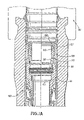
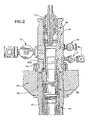
- FIGS. 1 to 8 are vertical axial sections showing successive steps in development and completion of the wellhead, the Figure numbers bearing the letter A being enlargements of part of the corresponding Figures of same number without the A;
- FIG. 9 is a circuit diagram showing external connections to the spool 3 ;
- FIGS. 11 and 12 are vertical axial sections showing alternative connectors to the upper end of the dual production bore wellhead during work over;
- FIG. 1 shows the upper end of a cased well having a wellhead housing 20 , in which casing hangers, including an uppermost production casing hanger 21 for, for example, 95 ⁇ 8′′ or 103 ⁇ 4′′, production casing is mounted in conventional manner
- FIG. 1 shows a conventional drilling BOP 22 having rams 23 and kill and choke lines 24 connected to the upper end of the housing 20 by a drilling connector 25 .
- FIG. 1A the usual mechanical seal assemblies between the production casing hanger 21 and the surrounding wellhead housing 20 have been removed and replaced through the BOP with an adapter 26 consisting of an outer annular body part 27 and an inner annular gland nut 28 which has a screw threaded connection to the body 27 so that it can be screwed between a lowered position shown on the right hand side of FIG. 1A , in which radial ducts 29 and 30 , respectively in the body 27 and nut 28 , are in communication with one another, and a raised position shown on the left hand side of FIG. 1A , in which the ducts are out of communication with one another.
- an adapter 26 consisting of an outer annular body part 27 and an inner annular gland nut 28 which has a screw threaded connection to the body 27 so that it can be screwed between a lowered position shown on the right hand side of FIG. 1A , in which radial ducts 29 and 30 , respectively in the body 27 and nut 28 , are in communication with one
- the duct 29 communicates through a conduit 31 between a depending portion of the body 27 and the housing 20 , and through a conduit 32 passing through the production casing hanger 21 , to the annulus surround the production casing.
- the duct 30 communicates through channels 33 formed in the radially inner surface of the nut 28 , and hence to a void to be described.
- the cooperation between the gland nut 28 and body 27 of the adapter therefore acts as a valve which can open and close a passage up past the production casing hanger from the production casing annulus.
- a tool is run in through the BOP and, by means by radially projecting spring lugs engaging in the channels 33 , rotates the gland nut 28 to the valve closed position shown on the right hand side on FIG. 1A .
- the well is thus resealed and the drilling 10 P 22 can temporarily be removed.
- two sets of sealing rings 40 provide, in series with the environmental seal, a production fluid seal externally between the ends to the spool tree mandrel 36 to the spool tree body and to the wellhead housing 20 .
- the intervening cavity can be tested through a test part 40 A.
- the provision of the adapter 26 is actually optional, and in its absence the lower end of the spool tree mandrel 36 may form a production seal directly with the production casing hanger 21 .
- the upper radially inner edge of the spool tree mandrel projects radially inwardly from the inner surface of the spool tree body above, to form a landing shoulder 42 and at least one machined key slot 43 is formed down through the landing shoulder.
- the sleeve 45 consists of an external cylindrical portion, an upper external surface of which is sealed by ring seals 46 to the spool tree 34 , and the lower external surface of which is sealed by an annular seal 47 to the production casing hanger 21 .
- a void 48 With which the channels 33 , now defined radially inwardly by the sleeve 45 , communicate.
- the void 48 in turn communicates via a duct 49 through the mandrel and body of the spool tree 34 to a lateral port.
- a lining which may be fixed in the cylindrical portion, or left after internal machining of the sleeve.
- This lining provides an orientation sleeve having an upper/edge forming a cam 50 .
- the lowermost portion of the cam leads into a key slot 51 .
- the keyed shoulder 56 of the tubing hanger lands in a complementary machined step in the spool tree 34 to ensure ultimate machined accuracy of orientation between the tubing hanger 54 and the spool tree 34 .
Abstract
Description
Claims (27)
Priority Applications (1)
| Application Number | Priority Date | Filing Date | Title |
|---|---|---|---|
| US11/459,828 US7308943B2 (en) | 1992-06-01 | 2006-07-25 | Well operations system |
Applications Claiming Priority (13)
| Application Number | Priority Date | Filing Date | Title |
|---|---|---|---|
| EPEP92305014 | 1992-06-01 | ||
| EP92305014A EP0572732B1 (en) | 1992-06-01 | 1992-06-01 | Wellhead |
| US08/204,397 US5544707A (en) | 1992-06-01 | 1993-05-28 | Wellhead |
| WOPCT/US93/05246 | 1993-05-28 | ||
| PCT/US1993/005246 WO1993024730A1 (en) | 1992-06-01 | 1993-05-28 | Wellhead |
| US08/679,560 US6039119A (en) | 1992-06-01 | 1996-07-12 | Completion system |
| US9254998A | 1998-06-05 | 1998-06-05 | |
| US09/657,018 US6547008B1 (en) | 1992-06-01 | 2000-09-07 | Well operations system |
| US10/366,173 US7093660B2 (en) | 1992-06-01 | 2003-02-13 | Well operations system |
| US10/844,871 US6991039B2 (en) | 1992-06-01 | 2004-05-13 | Well operations system |
| US11/078,121 US7117945B2 (en) | 1992-06-01 | 2005-03-10 | Well operations system |
| US11/077,587 US7314085B2 (en) | 1992-06-01 | 2005-03-10 | Well operations system |
| US11/459,828 US7308943B2 (en) | 1992-06-01 | 2006-07-25 | Well operations system |
Related Parent Applications (1)
| Application Number | Title | Priority Date | Filing Date |
|---|---|---|---|
| US11/078,121 Division US7117945B2 (en) | 1992-06-01 | 2005-03-10 | Well operations system |
Publications (2)
| Publication Number | Publication Date |
|---|---|
| US20060272823A1 US20060272823A1 (en) | 2006-12-07 |
| US7308943B2 true US7308943B2 (en) | 2007-12-18 |
Family
ID=8211385
Family Applications (10)
| Application Number | Title | Priority Date | Filing Date |
|---|---|---|---|
| US08/204,397 Expired - Lifetime US5544707A (en) | 1992-06-01 | 1993-05-28 | Wellhead |
| US08/679,560 Expired - Lifetime US6039119A (en) | 1992-06-01 | 1996-07-12 | Completion system |
| US09/657,018 Expired - Fee Related US6547008B1 (en) | 1992-06-01 | 2000-09-07 | Well operations system |
| US10/366,173 Expired - Fee Related US7093660B2 (en) | 1992-06-01 | 2003-02-13 | Well operations system |
| US10/844,871 Expired - Fee Related US6991039B2 (en) | 1992-06-01 | 2004-05-13 | Well operations system |
| US11/077,587 Expired - Fee Related US7314085B2 (en) | 1992-06-01 | 2005-03-10 | Well operations system |
| US11/078,121 Expired - Fee Related US7117945B2 (en) | 1992-06-01 | 2005-03-10 | Well operations system |
| US11/459,836 Expired - Fee Related US7314086B2 (en) | 1992-06-01 | 2006-07-25 | Well operations system |
| US11/459,828 Expired - Fee Related US7308943B2 (en) | 1992-06-01 | 2006-07-25 | Well operations system |
| US11/848,832 Expired - Fee Related US7500524B2 (en) | 1992-06-01 | 2007-08-31 | Well operations systems |
Family Applications Before (8)
| Application Number | Title | Priority Date | Filing Date |
|---|---|---|---|
| US08/204,397 Expired - Lifetime US5544707A (en) | 1992-06-01 | 1993-05-28 | Wellhead |
| US08/679,560 Expired - Lifetime US6039119A (en) | 1992-06-01 | 1996-07-12 | Completion system |
| US09/657,018 Expired - Fee Related US6547008B1 (en) | 1992-06-01 | 2000-09-07 | Well operations system |
| US10/366,173 Expired - Fee Related US7093660B2 (en) | 1992-06-01 | 2003-02-13 | Well operations system |
| US10/844,871 Expired - Fee Related US6991039B2 (en) | 1992-06-01 | 2004-05-13 | Well operations system |
| US11/077,587 Expired - Fee Related US7314085B2 (en) | 1992-06-01 | 2005-03-10 | Well operations system |
| US11/078,121 Expired - Fee Related US7117945B2 (en) | 1992-06-01 | 2005-03-10 | Well operations system |
| US11/459,836 Expired - Fee Related US7314086B2 (en) | 1992-06-01 | 2006-07-25 | Well operations system |
Family Applications After (1)
| Application Number | Title | Priority Date | Filing Date |
|---|---|---|---|
| US11/848,832 Expired - Fee Related US7500524B2 (en) | 1992-06-01 | 2007-08-31 | Well operations systems |
Country Status (8)
| Country | Link |
|---|---|
| US (10) | US5544707A (en) |
| EP (4) | EP0572732B1 (en) |
| AU (1) | AU664634B2 (en) |
| CA (1) | CA2116873C (en) |
| DE (5) | DE69226630T2 (en) |
| MX (1) | MX9303273A (en) |
| NO (1) | NO940958L (en) |
| WO (1) | WO1993024730A1 (en) |
Cited By (4)
| Publication number | Priority date | Publication date | Assignee | Title |
|---|---|---|---|---|
| US20080264643A1 (en) * | 2007-04-24 | 2008-10-30 | Brian Skeels | Lightweight device for remote subsea wireline intervention |
| US20100101800A1 (en) * | 2008-10-28 | 2010-04-29 | Cameron International Corporation | Subsea Completion with a Wellhead Annulus Access Adapter |
| US9279308B2 (en) | 2013-08-20 | 2016-03-08 | Onesubsea Llc | Vertical completion system including tubing hanger with valve |
| US11434719B2 (en) | 2021-02-01 | 2022-09-06 | Saudi Arabian Oil Company | Tubing casing annulus valve |
Families Citing this family (166)
| Publication number | Priority date | Publication date | Assignee | Title |
|---|---|---|---|---|
| DE69226630T2 (en) | 1992-06-01 | 1998-12-24 | Cooper Cameron Corp | Wellhead |
| US5372199A (en) * | 1993-02-16 | 1994-12-13 | Cooper Industries, Inc. | Subsea wellhead |
| US5865250A (en) | 1994-08-23 | 1999-02-02 | Abb Vetco Gray Inc. | Fluid connector with check valve and method of running a string of tubing |
| US5465794A (en) * | 1994-08-23 | 1995-11-14 | Abb Vetco Gray Inc. | Hydraulic seal between tubing hanger and wellhead |
| GB9418088D0 (en) * | 1994-09-08 | 1994-10-26 | Exploration & Prod Serv | Horizontal subsea tree pressure compensated plug |
| GB9514526D0 (en) * | 1995-07-15 | 1995-09-13 | Expro North Sea Ltd | Lightweight intervention system for use with horizontal tree with internal ball valve |
| GB9514510D0 (en) * | 1995-07-15 | 1995-09-13 | Expro North Sea Ltd | Lightweight intervention system |
| GB9519202D0 (en) * | 1995-09-20 | 1995-11-22 | Expro North Sea Ltd | Single bore riser system |
| GB9604803D0 (en) * | 1996-03-07 | 1996-05-08 | Expro North Sea Ltd | High pressure tree cap |
| US6056059A (en) * | 1996-03-11 | 2000-05-02 | Schlumberger Technology Corporation | Apparatus and method for establishing branch wells from a parent well |
| US5819852A (en) * | 1996-03-25 | 1998-10-13 | Fmc Corporation | Monobore completion/intervention riser system |
| US6062314A (en) | 1996-11-14 | 2000-05-16 | Abb Vetco Gray Inc. | Tubing hanger and tree with horizontal flow and annulus ports |
| EP0845577B1 (en) * | 1996-11-29 | 2002-07-31 | Cooper Cameron Corporation | Wellhead assembly |
| GB2320937B (en) * | 1996-12-02 | 2000-09-20 | Vetco Gray Inc Abb | Horizontal tree block for subsea wellhead |
| US6050339A (en) * | 1996-12-06 | 2000-04-18 | Abb Vetco Gray Inc. | Annulus porting of horizontal tree |
| US5868204A (en) * | 1997-05-08 | 1999-02-09 | Abb Vetco Gray Inc. | Tubing hanger vent |
| US5988282A (en) * | 1996-12-26 | 1999-11-23 | Abb Vetco Gray Inc. | Pressure compensated actuated check valve |
| US6082460A (en) * | 1997-01-21 | 2000-07-04 | Cooper Cameron Corporation | Apparatus and method for controlling hydraulic control fluid circuitry for a tubing hanger |
| US5927403A (en) * | 1997-04-21 | 1999-07-27 | Dallas; L. Murray | Apparatus for increasing the flow of production stimulation fluids through a wellhead |
| BR9809438A (en) * | 1997-04-29 | 2000-06-13 | Fmc Corp | Equipment and method for underwater connection of trees to underwater sources |
| WO1999018329A1 (en) * | 1997-10-07 | 1999-04-15 | Fmc Corporation | Slimbore subsea completion system and method |
| US6293345B1 (en) * | 1998-03-26 | 2001-09-25 | Dril-Quip, Inc. | Apparatus for subsea wells including valve passageway in the wall of the wellhead housing for access to the annulus |
| EP0952300B1 (en) * | 1998-03-27 | 2006-10-25 | Cooper Cameron Corporation | Method and apparatus for drilling a plurality of offshore underwater wells |
| US6202745B1 (en) * | 1998-10-07 | 2001-03-20 | Dril-Quip, Inc | Wellhead apparatus |
| GB2349662B (en) * | 1999-02-11 | 2001-01-31 | Fmc Corp | Large bore subsea christmas tree and tubing hanger system |
| US6253854B1 (en) * | 1999-02-19 | 2001-07-03 | Abb Vetco Gray, Inc. | Emergency well kill method |
| GB9911146D0 (en) * | 1999-05-14 | 1999-07-14 | Enhanced Recovery Limited Des | Method |
| US7111687B2 (en) | 1999-05-14 | 2006-09-26 | Des Enhanced Recovery Limited | Recovery of production fluids from an oil or gas well |
| GB2352258B (en) * | 1999-07-22 | 2003-09-17 | Plexus Ocean Syst Ltd | A wellhead arrangement |
| US6460621B2 (en) * | 1999-12-10 | 2002-10-08 | Abb Vetco Gray Inc. | Light-intervention subsea tree system |
| GB2366027B (en) * | 2000-01-27 | 2004-08-18 | Bell & Howell Postal Systems | Address learning system and method for using same |
| US20020100592A1 (en) * | 2001-01-26 | 2002-08-01 | Garrett Michael R. | Production flow tree cap |
| AU2001234764A1 (en) | 2000-02-02 | 2001-08-14 | Fmc Corporation | Non-intrusive pressure measurement device for subsea well casing annuli |
| GB2348659B (en) * | 2000-03-23 | 2001-03-28 | Fmc Corp | Tubing hanger saddle valve |
| US7025132B2 (en) * | 2000-03-24 | 2006-04-11 | Fmc Technologies, Inc. | Flow completion apparatus |
| EP1336721B1 (en) * | 2000-03-24 | 2006-11-29 | FMC Technologies, Inc. | Tubing head seal assembly |
| WO2001073325A2 (en) * | 2000-03-24 | 2001-10-04 | Fmc Corporation | Gate valve |
| BRPI0109756B8 (en) | 2000-03-24 | 2015-12-22 | Fmc Technologies | piping support and completion flow system. |
| EP1278936B1 (en) * | 2000-03-24 | 2005-06-08 | FMC Technologies, Inc. | Tubing hanger with annulus bore |
| GB2361726B (en) | 2000-04-27 | 2002-05-08 | Fmc Corp | Coiled tubing line deployment system |
| US7615893B2 (en) | 2000-05-11 | 2009-11-10 | Cameron International Corporation | Electric control and supply system |
| GB2362398B (en) | 2000-05-16 | 2002-11-13 | Fmc Corp | Device for installation and flow test of subsea completions |
| US6360822B1 (en) * | 2000-07-07 | 2002-03-26 | Abb Vetco Gray, Inc. | Casing annulus monitoring apparatus and method |
| GB2365890C (en) * | 2000-08-21 | 2006-02-07 | Fmc Corp | Multiple bore christmas tree outlet |
| US6695059B2 (en) * | 2000-10-23 | 2004-02-24 | Abb Vetco Gray Inc. | Mechanical anti-rotational feature for subsea wellhead housing |
| GB0027269D0 (en) | 2000-11-08 | 2000-12-27 | Donald Ian | Recovery of production fluids from an oil or gas well |
| US6516861B2 (en) | 2000-11-29 | 2003-02-11 | Cooper Cameron Corporation | Method and apparatus for injecting a fluid into a well |
| US6484807B2 (en) | 2000-11-29 | 2002-11-26 | Cooper Cameron Corporation | Wellhead assembly for injecting a fluid into a well and method of using the same |
| US6494267B2 (en) | 2000-11-29 | 2002-12-17 | Cooper Cameron Corporation | Wellhead assembly for accessing an annulus in a well and a method for its use |
| GB2370296B (en) * | 2000-12-20 | 2002-11-06 | Fmc Corp | Wellhead system comprising a sliding sleeve seal |
| GB0100565D0 (en) * | 2001-01-10 | 2001-02-21 | 2H Offshore Engineering Ltd | Operating a subsea well |
| BR0208799B1 (en) * | 2001-04-17 | 2011-09-06 | wellhead system. | |
| US7314088B2 (en) * | 2001-05-02 | 2008-01-01 | Shell Oil Company | System for retrieving a tubular element from a well |
| US6520263B2 (en) | 2001-05-18 | 2003-02-18 | Cooper Cameron Corporation | Retaining apparatus for use in a wellhead assembly and method for using the same |
| WO2002097008A2 (en) | 2001-05-25 | 2002-12-05 | Dril-Quip, Inc. | Horizontal spool tree assembly |
| GB2376485B (en) * | 2001-06-14 | 2003-08-27 | Kvaerner Oilfield Products Ltd | Annulus monitoring bleed |
| US6763891B2 (en) * | 2001-07-27 | 2004-07-20 | Abb Vetco Gray Inc. | Production tree with multiple safety barriers |
| BR0205883A (en) * | 2001-08-17 | 2003-11-18 | Kvaerner Oilfield Products Ltd | Wellhead housing installation, pressure monitoring / control system for an underwater wellhead arrangement and underwater wellhead arrangement |
| US6805200B2 (en) | 2001-08-20 | 2004-10-19 | Dril-Quip, Inc. | Horizontal spool tree wellhead system and method |
| US6659181B2 (en) * | 2001-11-13 | 2003-12-09 | Cooper Cameron Corporation | Tubing hanger with annulus bore |
| NO332032B1 (en) * | 2001-11-21 | 2012-05-29 | Vetco Gray Inc | Underwater wellhead assembly and method of completing an underwater well |
| CA2468433C (en) | 2001-11-27 | 2011-01-25 | Abb Vetco Gray Inc. | A wellhead assembly for communicating with the casing hanger annulus |
| US7044227B2 (en) * | 2001-12-10 | 2006-05-16 | Vetco Gray Inc. | Subsea well injection and monitoring system |
| US20030121667A1 (en) * | 2001-12-28 | 2003-07-03 | Alfred Massie | Casing hanger annulus monitoring system |
| US6705401B2 (en) | 2002-01-04 | 2004-03-16 | Abb Vetco Gray Inc. | Ported subsea wellhead |
| CA2382904C (en) * | 2002-04-22 | 2005-04-12 | Daniel J. Riddell | Wellhead production pumping tree with access port |
| US6666266B2 (en) | 2002-05-03 | 2003-12-23 | Halliburton Energy Services, Inc. | Screw-driven wellhead isolation tool |
| US7063160B2 (en) * | 2002-07-30 | 2006-06-20 | Vetco Gray Inc. | Non-orienting tubing hanger system with a flow cage |
| AU2003263874A1 (en) * | 2002-08-16 | 2004-03-03 | Dril-Quip, Inc. | Horizontal spool tree wellhead system and method |
| WO2004025074A1 (en) * | 2002-08-22 | 2004-03-25 | Fmc Technologies, Inc. | Apparatus and method for installation of subsea well completion systems |
| WO2004025068A2 (en) * | 2002-09-12 | 2004-03-25 | Dril-Quip, Inc. | System and method for well workover with horizontal tree |
| BR0316189B1 (en) * | 2002-11-12 | 2014-08-26 | Vetco Gray Inc | GUIDANCE SYSTEM AND METHOD FOR A SUBSEA WELL |
| US6966383B2 (en) * | 2002-12-12 | 2005-11-22 | Dril-Quip, Inc. | Horizontal spool tree with improved porting |
| GB2397312B (en) * | 2003-01-17 | 2005-07-27 | Fmc Technologies | Well completion system |
| US6966381B2 (en) * | 2003-04-09 | 2005-11-22 | Cooper Cameron Corporation | Drill-through spool body sleeve assembly |
| NO322829B1 (en) * | 2003-05-22 | 2006-12-11 | Fmc Kongsberg Subsea As | Resealable plug, valve tree with plug and well intervention procedure in wells with at least one plug |
| EP2216503B1 (en) | 2003-05-31 | 2013-12-11 | Cameron Systems (Ireland) Limited | Apparatus and method for recovering fluids from a well and/or injecting fluids into a well |
| US20040262010A1 (en) * | 2003-06-26 | 2004-12-30 | Milberger Lionel J. | Horizontal tree assembly |
| CA2476575C (en) * | 2003-08-05 | 2012-01-10 | Stream-Flo Industries Ltd. | Method and apparatus to provide electrical connection in a wellhead for a downhole electrical device |
| US7552762B2 (en) * | 2003-08-05 | 2009-06-30 | Stream-Flo Industries Ltd. | Method and apparatus to provide electrical connection in a wellhead for a downhole electrical device |
| AU2003904183A0 (en) | 2003-08-08 | 2003-08-21 | Woodside Energy Limited | Method for completion or work-over of a sub-sea well using a horizontal christmas tree |
| US7296629B2 (en) * | 2003-10-20 | 2007-11-20 | Fmc Technologies, Inc. | Subsea completion system, and methods of using same |
| US7647595B2 (en) * | 2003-10-29 | 2010-01-12 | Oracle International Corporation | Efficient event notification in clustered computing environments |
| US7121346B2 (en) * | 2003-11-18 | 2006-10-17 | Cameron International Corporation | Intervention spool for subsea use |
| CA2555403C (en) | 2004-02-26 | 2012-08-21 | Des Enhanced Recovery Limited | Connection system for subsea flow interface equipment |
| US7331396B2 (en) * | 2004-03-16 | 2008-02-19 | Dril-Quip, Inc. | Subsea production systems |
| GB0409189D0 (en) | 2004-04-24 | 2004-05-26 | Expro North Sea Ltd | Plug setting and retrieving apparatus |
| US20050242519A1 (en) * | 2004-04-29 | 2005-11-03 | Koleilat Bashir M | Wedge seal |
| GB2415720B (en) * | 2004-06-28 | 2007-04-11 | Dril Quip Inc | Pressure-compensated flow shut-off sleeve for wellhead and subsea well assembly including same |
| US7467663B2 (en) * | 2004-09-07 | 2008-12-23 | Dril-Quip, Inc. | High pressure wellhead assembly interface |
| US7490673B2 (en) * | 2004-10-06 | 2009-02-17 | Fmc Technologies, Inc. | Universal connection interface for subsea completion systems |
| US7861789B2 (en) * | 2005-02-09 | 2011-01-04 | Vetco Gray Inc. | Metal-to-metal seal for bridging hanger or tieback connection |
| US7419001B2 (en) | 2005-05-18 | 2008-09-02 | Azura Energy Systems, Inc. | Universal tubing hanger suspension assembly and well completion system and method of using same |
| CN101208495B (en) * | 2005-05-18 | 2013-03-20 | 阿古斯萨伯希股份有限公司 | Universal tubing hanger suspension assembly and well completion system and method of using same |
| US8286713B2 (en) * | 2005-05-18 | 2012-10-16 | Argus Subsea, Inc. | Oil and gas well completion system and method of installation |
| GB2432172B (en) * | 2005-11-09 | 2008-07-02 | Aker Kvaerner Subsea Ltd | Subsea trees and caps for them |
| US9234393B2 (en) * | 2006-01-24 | 2016-01-12 | Helix Well Ops (U.K.) Limited | Bore selector |
| US7607485B2 (en) * | 2006-01-26 | 2009-10-27 | Vetco Gray Inc. | Tubing hanger and wellhead housing with mating tubing annulus passages |
| US7909103B2 (en) * | 2006-04-20 | 2011-03-22 | Vetcogray Inc. | Retrievable tubing hanger installed below tree |
| US7599469B2 (en) * | 2006-04-28 | 2009-10-06 | Cameron International Corporation | Non-intrusive pressure gage |
| US7798231B2 (en) * | 2006-07-06 | 2010-09-21 | Vetco Gray Inc. | Adapter sleeve for wellhead housing |
| US7699110B2 (en) * | 2006-07-19 | 2010-04-20 | Baker Hughes Incorporated | Flow diverter tool assembly and methods of using same |
| GB2440940B (en) * | 2006-08-18 | 2009-12-16 | Cameron Internat Corp Us | Wellhead assembly |
| GB0618001D0 (en) | 2006-09-13 | 2006-10-18 | Des Enhanced Recovery Ltd | Method |
| US9127534B2 (en) * | 2006-10-31 | 2015-09-08 | Halliburton Energy Services, Inc. | Cable integrity monitor for electromagnetic telemetry systems |
| GB0625526D0 (en) | 2006-12-18 | 2007-01-31 | Des Enhanced Recovery Ltd | Apparatus and method |
| GB0625191D0 (en) | 2006-12-18 | 2007-01-24 | Des Enhanced Recovery Ltd | Apparatus and method |
| EP2129333B1 (en) * | 2007-02-16 | 2019-04-03 | Medtronic, Inc | Replacement prosthetic heart valves |
| US20090071656A1 (en) * | 2007-03-23 | 2009-03-19 | Vetco Gray Inc. | Method of running a tubing hanger and internal tree cap simultaneously |
| US7743832B2 (en) * | 2007-03-23 | 2010-06-29 | Vetco Gray Inc. | Method of running a tubing hanger and internal tree cap simultaneously |
| US8011436B2 (en) * | 2007-04-05 | 2011-09-06 | Vetco Gray Inc. | Through riser installation of tree block |
| BRPI0820569A2 (en) * | 2007-11-05 | 2012-12-18 | Cameron Int Corp | annular seal assembly and method of forming an annular seal |
| NO333955B1 (en) * | 2007-11-23 | 2013-10-28 | Fmc Kongsberg Subsea As | Underwater horizontal Christmas tree |
| US20090158298A1 (en) * | 2007-12-12 | 2009-06-18 | Abhishek Saxena | Database system and eventing infrastructure |
| BRPI0820743A2 (en) * | 2007-12-12 | 2015-06-16 | Cameron Int Corp | Function reel |
| WO2009079124A1 (en) * | 2007-12-14 | 2009-06-25 | Cameron International Corporation | Safety device for retrieving component within wellhead |
| GB2469216B (en) | 2007-12-20 | 2011-07-13 | Cameron Int Corp | System and method for snubbing under pressure |
| US8899315B2 (en) * | 2008-02-25 | 2014-12-02 | Cameron International Corporation | Systems, methods, and devices for isolating portions of a wellhead from fluid pressure |
| US8701756B2 (en) | 2008-03-25 | 2014-04-22 | Cameron International Corporation | Internal lockdown snubbing plug |
| WO2009120935A2 (en) * | 2008-03-28 | 2009-10-01 | Cameron International Corporation | Wellhead hanger shoulder |
| US8662184B2 (en) * | 2008-04-15 | 2014-03-04 | Cameron International Corporation | Multi-section tree completion system |
| GB0815035D0 (en) * | 2008-08-16 | 2008-09-24 | Aker Subsea Ltd | Wellhead annulus monitoring |
| NO329610B1 (en) * | 2008-12-02 | 2010-11-22 | West Oil Tools As | Wellhead with integrated safety valve and method of manufacture and use of the same |
| GB2466514B (en) * | 2008-12-24 | 2012-09-05 | Weatherford France Sas | Wellhead downhole line communication arrangement |
| US8602658B2 (en) * | 2010-02-05 | 2013-12-10 | Baker Hughes Incorporated | Spoolable signal conduction and connection line and method |
| US8397828B2 (en) * | 2010-03-25 | 2013-03-19 | Baker Hughes Incorporated | Spoolable downhole control system and method |
| US8794334B2 (en) | 2010-08-25 | 2014-08-05 | Cameron International Corporation | Modular subsea completion |
| GB2484298A (en) * | 2010-10-05 | 2012-04-11 | Plexus Ocean Syst Ltd | Subsea wellhead with adjustable hanger forming an annular seal |
| US8668020B2 (en) * | 2010-11-19 | 2014-03-11 | Weatherford/Lamb, Inc. | Emergency bowl for deploying control line from casing head |
| GB2486451B (en) * | 2010-12-15 | 2013-01-16 | Verderg Connectors Ltd | Connection apparatus and method |
| US20120152564A1 (en) * | 2010-12-16 | 2012-06-21 | Terry Peltier | Horizontal production tree and method of use thereof |
| US8746350B2 (en) * | 2010-12-22 | 2014-06-10 | Vetco Gray Inc. | Tubing hanger shuttle valve |
| US8997872B1 (en) * | 2012-02-22 | 2015-04-07 | Trendsetter Engineering, Inc. | Cap assembly for use with a tubing spool of a wellhead |
| US9376881B2 (en) * | 2012-03-23 | 2016-06-28 | Vetco Gray Inc. | High-capacity single-trip lockdown bushing and a method to operate the same |
| US9784063B2 (en) | 2012-08-17 | 2017-10-10 | Onesubsea Ip Uk Limited | Subsea production system with downhole equipment suspension system |
| US9404332B2 (en) | 2012-10-08 | 2016-08-02 | Onesubsea Ip Uk Limited | Well system with an independently retrievable tree |
| US8973664B2 (en) * | 2012-10-24 | 2015-03-10 | Vetco Gray Inc. | Subsea wellhead stabilization using cylindrical sockets |
| US9273531B2 (en) * | 2013-12-06 | 2016-03-01 | Ge Oil & Gas Uk Limited | Orientation adapter for use with a tubing hanger |
| US9506329B2 (en) | 2014-02-28 | 2016-11-29 | Cameron International Corporation | Rotating hanger |
| US9376872B2 (en) * | 2014-03-12 | 2016-06-28 | Onesubsea Ip Uk Limited | Tubing hanger orientation spool |
| WO2015191417A1 (en) * | 2014-06-09 | 2015-12-17 | Schlumberger Canada Limited | System and methodology using annulus access valve |
| US10309190B2 (en) * | 2014-07-23 | 2019-06-04 | Onesubsea Ip Uk Limited | System and method for accessing a well |
| BR112017001215B1 (en) * | 2014-07-25 | 2022-03-15 | Helix Energy Solutions Group, Inc | Subsea containment method and system |
| CN104227383A (en) * | 2014-09-26 | 2014-12-24 | 宁波旭升机械有限公司 | Oil pipe press mounting device |
| US9765593B2 (en) * | 2014-12-03 | 2017-09-19 | Ge Oil & Gas Uk Limited | Configurable subsea tree master valve block |
| US9341045B1 (en) * | 2014-12-03 | 2016-05-17 | Ge Oil & Gas Uk Limited | Configurable subsea tree master valve block |
| US9909380B2 (en) | 2015-02-25 | 2018-03-06 | Onesubsea Ip Uk Limited | System and method for accessing a well |
| US9523259B2 (en) * | 2015-03-05 | 2016-12-20 | Ge Oil & Gas Uk Limited | Vertical subsea tree annulus and controls access |
| CN109477364A (en) | 2016-05-02 | 2019-03-15 | 卡梅伦技术有限公司 | Drilling well and production system component with wide flange body |
| MX2018016190A (en) * | 2016-06-30 | 2019-06-10 | A Bowen Billy JR | Test-port activated tubing hanger control valve. |
| GB2558267B (en) | 2016-12-23 | 2021-09-15 | Equinor Energy As | Subsea wellhead monitoring and controlling |
| US20180313187A1 (en) * | 2017-05-01 | 2018-11-01 | Schlumberger Technology Corporation | Single body choke line and kill line valves |
| US10900314B2 (en) * | 2017-12-21 | 2021-01-26 | Spoked Solutions LLC | Riser system |
| CN108086937A (en) * | 2018-01-12 | 2018-05-29 | 科莱斯(天津)电热科技有限公司 | A kind of high-pressure well mouth hanger controls total valve gear |
| US10989002B2 (en) | 2018-02-26 | 2021-04-27 | Innovex Downhole Solutions, Inc. | Cable pack-off apparatus for well having electrical submersible pump |
| US20200032607A1 (en) * | 2018-07-24 | 2020-01-30 | Ensco International Incorporated | Well reentry |
| GB2586965A (en) * | 2019-08-29 | 2021-03-17 | Ge Oil & Gas Uk Ltd | Wellhead apparatus, assembly and method for supporting downhole tubing |
| WO2021127450A1 (en) * | 2019-12-20 | 2021-06-24 | Cameron International Corporation | System and method for setting a barrier in a well string |
| GB202011951D0 (en) * | 2020-07-31 | 2020-09-16 | Baker Hughes Energy Tech Uk Limited | Tubing head spool and method of drilling a well using the tubing head spool |
| GB2600771B (en) * | 2020-11-10 | 2023-03-01 | Aker Solutions As | Wellhead system |
| WO2022149983A1 (en) * | 2021-01-10 | 2022-07-14 | Ccb Subsea As | Kit and method for modification of a horizontal valve tree |
| CN113187427B (en) * | 2021-04-28 | 2022-11-29 | 中国海洋石油集团有限公司 | Drilling-through type underwater horizontal Christmas tree and wellhead system |
| CN114517655A (en) * | 2021-12-27 | 2022-05-20 | 深圳市百勤石油技术有限公司 | Economic small-wellhead gas production tree system suitable for natural gas hydrate exploitation |
| WO2023212505A1 (en) * | 2022-04-26 | 2023-11-02 | Conocophillips Company | Temporary suspension of completed hydrocarbon wells |
| US11873693B2 (en) * | 2022-05-31 | 2024-01-16 | Saudi Arabian Oil Company | Cutting a valve within a well stack |
| CN115306341B (en) * | 2022-10-12 | 2022-12-16 | 大庆市华禹石油机械制造有限公司 | Carbon dioxide drives gas production wellhead assembly that possesses corrosion protection performance |
Citations (46)
| Publication number | Priority date | Publication date | Assignee | Title |
|---|---|---|---|---|
| US2094812A (en) * | 1937-10-05 | Flow control heab | ||
| US2118094A (en) * | 1937-04-12 | 1938-05-24 | Mcdonough James Moore | Combination casing head and christmas tree |
| US2148360A (en) * | 1937-12-30 | 1939-02-21 | Gray Tool Co | Oil well casing head and tubing hanger |
| US2590688A (en) * | 1946-11-14 | 1952-03-25 | Gray Tool Co | Well manifold |
| US2889886A (en) * | 1956-01-23 | 1959-06-09 | Jay P Gould | Well head |
| US2965174A (en) * | 1958-01-27 | 1960-12-20 | Shell Oil Co | Off-shore well installation and method |
| US3041090A (en) * | 1959-04-28 | 1962-06-26 | Shell Oil Co | Pivoted tubing well connection |
| US3043371A (en) * | 1959-07-14 | 1962-07-10 | Rector Well Equipment Company | Valved tubing hanger |
| US3064735A (en) * | 1959-08-17 | 1962-11-20 | Shell Oil Co | Wellhead assembly lock-down apparatus |
| US3090640A (en) * | 1959-05-04 | 1963-05-21 | Shell Oil Co | Well casing and tubing suspension assembly |
| US3098525A (en) * | 1961-04-27 | 1963-07-23 | Shell Oil Co | Apparatus for installing and retrieving equipment from underwater wells |
| US3139932A (en) * | 1961-11-28 | 1964-07-07 | Shell Oil Co | Wellhead with tool diverter |
| US3236308A (en) * | 1960-04-04 | 1966-02-22 | Richfield Oil Corp | Drilling apparatus and method |
| US3279536A (en) * | 1961-04-03 | 1966-10-18 | Richfield Oil Corp | Submarine drilling and production head and method of installing same |
| US3295600A (en) * | 1963-09-20 | 1967-01-03 | Richfield Oil Corp | Underwater production method |
| US3299958A (en) * | 1965-04-02 | 1967-01-24 | Fmc Corp | Unitized well head |
| US3310107A (en) * | 1963-10-23 | 1967-03-21 | Fmc Corp | Underwater well method and apparatus |
| US3331437A (en) * | 1965-01-06 | 1967-07-18 | Cameron Iron Works Inc | Wellhead assembly |
| US3332481A (en) * | 1961-04-03 | 1967-07-25 | Richfield Oil Corp | Method of installing submarine drilling and production head |
| US3414056A (en) * | 1967-03-06 | 1968-12-03 | Brown Oil Tools | Wellhead apparatus |
| US3437149A (en) * | 1967-05-31 | 1969-04-08 | Shaffer Tool Works | Cable feed-through means and method for well head constructions |
| US3454084A (en) * | 1967-10-10 | 1969-07-08 | Otis Eng Corp | Well head closure assembly |
| US3457992A (en) * | 1966-12-14 | 1969-07-29 | Atlantic Richfield Co | Underwater tubing head |
| US3542125A (en) * | 1968-11-12 | 1970-11-24 | Otis Eng Corp | Well apparatus |
| US3545541A (en) * | 1968-08-08 | 1970-12-08 | Shell Oil Co | Wellhead assembly including diverter means |
| US3552903A (en) * | 1968-06-28 | 1971-01-05 | Mobil Oil Corp | Subsea production satellite |
| US3602303A (en) * | 1967-12-01 | 1971-08-31 | Amoco Prod Co | Subsea wellhead completion systems |
| US3638732A (en) * | 1970-01-12 | 1972-02-01 | Vetco Offshore Ind Inc | Underwater wellhead electric connection apparatus for submerged electric motor driven well pumps and method of installation |
| US3638725A (en) * | 1970-05-15 | 1972-02-01 | Vetco Offshore Ind Inc | Direct drive casing hanger apparatus |
| US3662822A (en) * | 1969-05-12 | 1972-05-16 | Atlantic Richfield Co | Method for producing a benthonic well |
| US3971576A (en) | 1971-01-04 | 1976-07-27 | Mcevoy Oilfield Equipment Co. | Underwater well completion method and apparatus |
| US4116044A (en) * | 1977-04-28 | 1978-09-26 | Fmc Corporation | Packoff leak detector |
| US4130161A (en) * | 1977-09-06 | 1978-12-19 | Cameron Iron Works, Inc. | Underwater Christmas tree |
| US4154302A (en) * | 1977-10-31 | 1979-05-15 | Shafco Industries, Inc. | Cable feed-through method and apparatus for well head constructions |
| US4289199A (en) * | 1979-09-28 | 1981-09-15 | Combustion Engineering, Inc. | Wellhead sidewall electrical penetrator |
| US4491176A (en) * | 1982-10-01 | 1985-01-01 | Reed Lehman T | Electric power supplying well head assembly |
| WO1986001852A1 (en) | 1984-09-12 | 1986-03-27 | Britoil Plc | Underwater well equipment |
| US4629003A (en) * | 1985-08-01 | 1986-12-16 | Baugh Benton F | Guilelineless subsea completion system with horizontal flowline connection |
| GB2192921A (en) | 1986-07-19 | 1988-01-27 | James Arthur Graser | Wellhead apparatus |
| US4887672A (en) | 1988-12-16 | 1989-12-19 | Cameron Iron Works Usa, Inc. | Subsea wellhead with annulus communicating system |
| US4903774A (en) * | 1988-01-28 | 1990-02-27 | The British Petroleum Company P.L.C. | Annulus shut-off mechanism |
| WO1992000438A1 (en) | 1990-06-26 | 1992-01-09 | Framo Developments (Uk) Limited | Subsea pump system |
| US5092401A (en) * | 1989-08-17 | 1992-03-03 | Shell Oil Company | Wellhead assembly |
| EP0572732A1 (en) | 1992-06-01 | 1993-12-08 | Cooper Cameron Corporation | Wellhead |
| US5372199A (en) * | 1993-02-16 | 1994-12-13 | Cooper Industries, Inc. | Subsea wellhead |
| US5884706A (en) * | 1994-09-08 | 1999-03-23 | Expro North Sea Limited | Horizontal subsea tree pressure compensated plug |
Family Cites Families (38)
| Publication number | Priority date | Publication date | Assignee | Title |
|---|---|---|---|---|
| US2478628A (en) * | 1947-01-27 | 1949-08-09 | Shell Dev | Testing casing heads |
| US2954742A (en) * | 1957-04-29 | 1960-10-04 | Clifford C Williams | Water pump unit |
| US2951363A (en) * | 1957-09-20 | 1960-09-06 | Jersey Prod Res Co | Tool for testing well head equipment |
| US3451481A (en) * | 1966-06-09 | 1969-06-24 | Rockwell Mfg Co | Dual suspension and seal |
| NL7017510A (en) * | 1969-12-29 | 1971-07-01 | ||
| US3628725A (en) * | 1970-01-16 | 1971-12-21 | Mattel Inc | Compact toy lap counter |
| CA1034488A (en) * | 1975-09-10 | 1978-07-11 | Mcevoy Oilfield Equipment Co. | Seal |
| GB1494301A (en) * | 1976-04-20 | 1977-12-07 | Gray Tool Co | Adjustable suspension of well tubing |
| SU625021A1 (en) * | 1977-01-06 | 1978-09-25 | Башкирский государственный научно-исследовательский и проектный институт нефтяной промышленности | Automatic valve device |
| IT1148764B (en) * | 1980-02-19 | 1986-12-03 | Saipem Spa | INFLANGEMENT FOR THE SUSPENSION OF COLUMNS OF COATING AND PRODUCTION PIPES FOR HIGH PRESSURE PETROLEUM OR GASES |
| US4436148A (en) * | 1981-04-27 | 1984-03-13 | Richard Maxwell | Chemical treatment for oil wells |
| US4455040A (en) * | 1981-08-03 | 1984-06-19 | Smith International, Inc. | High-pressure wellhead seal |
| CA1208123A (en) * | 1983-07-19 | 1986-07-22 | Barber Industries, Ltd. | Wellhead sealing system |
| US4541753A (en) * | 1983-07-22 | 1985-09-17 | Shell Oil Company | Subsea pipeline connection |
| US4569540A (en) * | 1983-12-29 | 1986-02-11 | Beson Technology, Inc. | Piping suspender with metal-to-metal seal |
| SU1244285A1 (en) * | 1984-11-30 | 1986-07-15 | Азербайджанский научно-исследовательский и проектно-конструкторский институт нефтяного машиностроения | Well-head connector |
| SU1659625A1 (en) * | 1989-07-25 | 1991-06-30 | Военизированная Часть По Предупреждению Возникновения И По Ликвидации Открытых Газовых И Нефтяных Фонтанов Северо-Восточного Промышленного Района | Wellhead setup equipment |
| US5143158A (en) | 1990-04-27 | 1992-09-01 | Dril-Quip, Inc. | Subsea wellhead apparatus |
| US5103915A (en) * | 1990-08-17 | 1992-04-14 | Abb Vetco Gray Inc. | Wellhead housing seal assembly for damaged sealing surfaces |
| US5141257A (en) * | 1991-09-23 | 1992-08-25 | Cooper Industries, Inc. | High preload mechanical connector |
| US5280706A (en) * | 1992-06-25 | 1994-01-25 | Thiokol Corporation | Composite/metal hybrid rocket motor case and methods for manufacturing |
| GB2286840B (en) | 1994-02-10 | 1997-09-03 | Fmc Corp | Safety valve for horizontal tree |
| US5573336A (en) * | 1995-08-31 | 1996-11-12 | The Torrington Company | Seal for a spherical plain bearing |
| US5819852A (en) * | 1996-03-25 | 1998-10-13 | Fmc Corporation | Monobore completion/intervention riser system |
| US6062314A (en) * | 1996-11-14 | 2000-05-16 | Abb Vetco Gray Inc. | Tubing hanger and tree with horizontal flow and annulus ports |
| US6003602A (en) * | 1997-09-05 | 1999-12-21 | Kraerner Oilfield Products | Tree bore protector |
| WO1999018329A1 (en) | 1997-10-07 | 1999-04-15 | Fmc Corporation | Slimbore subsea completion system and method |
| US5975210A (en) * | 1997-12-31 | 1999-11-02 | Kvaerner Oilfield Products | Well completion system having a precision cut low profile helix |
| US6293345B1 (en) * | 1998-03-26 | 2001-09-25 | Dril-Quip, Inc. | Apparatus for subsea wells including valve passageway in the wall of the wellhead housing for access to the annulus |
| WO2000047864A1 (en) | 1999-02-11 | 2000-08-17 | Fmc Corporation | Subsea completion apparatus |
| US6470968B1 (en) | 1999-10-06 | 2002-10-29 | Kvaerner Oifield Products, Inc. | Independently retrievable subsea tree and tubing hanger system |
| BRPI0109756B8 (en) | 2000-03-24 | 2015-12-22 | Fmc Technologies | piping support and completion flow system. |
| EP1278936B1 (en) | 2000-03-24 | 2005-06-08 | FMC Technologies, Inc. | Tubing hanger with annulus bore |
| WO2001073325A2 (en) | 2000-03-24 | 2001-10-04 | Fmc Corporation | Gate valve |
| US6626245B1 (en) | 2000-03-29 | 2003-09-30 | L Murray Dallas | Blowout preventer protector and method of using same |
| US6360822B1 (en) | 2000-07-07 | 2002-03-26 | Abb Vetco Gray, Inc. | Casing annulus monitoring apparatus and method |
| US6516861B2 (en) * | 2000-11-29 | 2003-02-11 | Cooper Cameron Corporation | Method and apparatus for injecting a fluid into a well |
| US6805200B2 (en) | 2001-08-20 | 2004-10-19 | Dril-Quip, Inc. | Horizontal spool tree wellhead system and method |
-
1992
- 1992-06-01 DE DE69226630T patent/DE69226630T2/en not_active Expired - Lifetime
- 1992-06-01 EP EP92305014A patent/EP0572732B1/en not_active Expired - Lifetime
- 1992-06-01 DE DE0719905T patent/DE719905T1/en active Pending
- 1992-06-01 DE DE69231713T patent/DE69231713T3/en not_active Expired - Lifetime
- 1992-06-01 DE DE69232736T patent/DE69232736T2/en not_active Expired - Lifetime
- 1992-06-01 EP EP96101005A patent/EP0719905B2/en not_active Expired - Lifetime
- 1992-06-01 EP EP99122799A patent/EP0989283B1/en not_active Revoked
- 1992-06-01 EP EP02100394A patent/EP1233145A3/en not_active Withdrawn
- 1992-06-01 DE DE0989283T patent/DE989283T1/en active Pending
-
1993
- 1993-05-28 AU AU44031/93A patent/AU664634B2/en not_active Expired
- 1993-05-28 WO PCT/US1993/005246 patent/WO1993024730A1/en active Application Filing
- 1993-05-28 US US08/204,397 patent/US5544707A/en not_active Expired - Lifetime
- 1993-05-28 CA CA002116873A patent/CA2116873C/en not_active Expired - Lifetime
- 1993-06-01 MX MX9303273A patent/MX9303273A/en unknown
-
1994
- 1994-03-16 NO NO940958A patent/NO940958L/en unknown
-
1996
- 1996-07-12 US US08/679,560 patent/US6039119A/en not_active Expired - Lifetime
-
2000
- 2000-09-07 US US09/657,018 patent/US6547008B1/en not_active Expired - Fee Related
-
2003
- 2003-02-13 US US10/366,173 patent/US7093660B2/en not_active Expired - Fee Related
-
2004
- 2004-05-13 US US10/844,871 patent/US6991039B2/en not_active Expired - Fee Related
-
2005
- 2005-03-10 US US11/077,587 patent/US7314085B2/en not_active Expired - Fee Related
- 2005-03-10 US US11/078,121 patent/US7117945B2/en not_active Expired - Fee Related
-
2006
- 2006-07-25 US US11/459,836 patent/US7314086B2/en not_active Expired - Fee Related
- 2006-07-25 US US11/459,828 patent/US7308943B2/en not_active Expired - Fee Related
-
2007
- 2007-08-31 US US11/848,832 patent/US7500524B2/en not_active Expired - Fee Related
Patent Citations (54)
| Publication number | Priority date | Publication date | Assignee | Title |
|---|---|---|---|---|
| US2094812A (en) * | 1937-10-05 | Flow control heab | ||
| US2118094A (en) * | 1937-04-12 | 1938-05-24 | Mcdonough James Moore | Combination casing head and christmas tree |
| US2148360A (en) * | 1937-12-30 | 1939-02-21 | Gray Tool Co | Oil well casing head and tubing hanger |
| US2590688A (en) * | 1946-11-14 | 1952-03-25 | Gray Tool Co | Well manifold |
| US2889886A (en) * | 1956-01-23 | 1959-06-09 | Jay P Gould | Well head |
| US2965174A (en) * | 1958-01-27 | 1960-12-20 | Shell Oil Co | Off-shore well installation and method |
| US3041090A (en) * | 1959-04-28 | 1962-06-26 | Shell Oil Co | Pivoted tubing well connection |
| US3090640A (en) * | 1959-05-04 | 1963-05-21 | Shell Oil Co | Well casing and tubing suspension assembly |
| US3043371A (en) * | 1959-07-14 | 1962-07-10 | Rector Well Equipment Company | Valved tubing hanger |
| US3064735A (en) * | 1959-08-17 | 1962-11-20 | Shell Oil Co | Wellhead assembly lock-down apparatus |
| US3236308A (en) * | 1960-04-04 | 1966-02-22 | Richfield Oil Corp | Drilling apparatus and method |
| US3279536A (en) * | 1961-04-03 | 1966-10-18 | Richfield Oil Corp | Submarine drilling and production head and method of installing same |
| US3332481A (en) * | 1961-04-03 | 1967-07-25 | Richfield Oil Corp | Method of installing submarine drilling and production head |
| US3098525A (en) * | 1961-04-27 | 1963-07-23 | Shell Oil Co | Apparatus for installing and retrieving equipment from underwater wells |
| US3139932A (en) * | 1961-11-28 | 1964-07-07 | Shell Oil Co | Wellhead with tool diverter |
| US3295600A (en) * | 1963-09-20 | 1967-01-03 | Richfield Oil Corp | Underwater production method |
| US3310107A (en) * | 1963-10-23 | 1967-03-21 | Fmc Corp | Underwater well method and apparatus |
| US3331437A (en) * | 1965-01-06 | 1967-07-18 | Cameron Iron Works Inc | Wellhead assembly |
| US3299958A (en) * | 1965-04-02 | 1967-01-24 | Fmc Corp | Unitized well head |
| US3457992A (en) * | 1966-12-14 | 1969-07-29 | Atlantic Richfield Co | Underwater tubing head |
| US3414056A (en) * | 1967-03-06 | 1968-12-03 | Brown Oil Tools | Wellhead apparatus |
| US3437149A (en) * | 1967-05-31 | 1969-04-08 | Shaffer Tool Works | Cable feed-through means and method for well head constructions |
| US3454084A (en) * | 1967-10-10 | 1969-07-08 | Otis Eng Corp | Well head closure assembly |
| US3602303A (en) * | 1967-12-01 | 1971-08-31 | Amoco Prod Co | Subsea wellhead completion systems |
| US3552903A (en) * | 1968-06-28 | 1971-01-05 | Mobil Oil Corp | Subsea production satellite |
| US3545541A (en) * | 1968-08-08 | 1970-12-08 | Shell Oil Co | Wellhead assembly including diverter means |
| US3542125A (en) * | 1968-11-12 | 1970-11-24 | Otis Eng Corp | Well apparatus |
| US3662822A (en) * | 1969-05-12 | 1972-05-16 | Atlantic Richfield Co | Method for producing a benthonic well |
| US3638732A (en) * | 1970-01-12 | 1972-02-01 | Vetco Offshore Ind Inc | Underwater wellhead electric connection apparatus for submerged electric motor driven well pumps and method of installation |
| US3638725A (en) * | 1970-05-15 | 1972-02-01 | Vetco Offshore Ind Inc | Direct drive casing hanger apparatus |
| US4053023A (en) * | 1971-01-04 | 1977-10-11 | Mcevoy Oilfield Equipment Co. | Underwater well completion method and apparatus |
| US3971576A (en) | 1971-01-04 | 1976-07-27 | Mcevoy Oilfield Equipment Co. | Underwater well completion method and apparatus |
| US4116044A (en) * | 1977-04-28 | 1978-09-26 | Fmc Corporation | Packoff leak detector |
| US4130161A (en) * | 1977-09-06 | 1978-12-19 | Cameron Iron Works, Inc. | Underwater Christmas tree |
| US4154302A (en) * | 1977-10-31 | 1979-05-15 | Shafco Industries, Inc. | Cable feed-through method and apparatus for well head constructions |
| US4289199A (en) * | 1979-09-28 | 1981-09-15 | Combustion Engineering, Inc. | Wellhead sidewall electrical penetrator |
| US4491176A (en) * | 1982-10-01 | 1985-01-01 | Reed Lehman T | Electric power supplying well head assembly |
| WO1986001852A1 (en) | 1984-09-12 | 1986-03-27 | Britoil Plc | Underwater well equipment |
| GB2166775A (en) * | 1984-09-12 | 1986-05-14 | Britoil Plc | Underwater well equipment |
| US4629003A (en) * | 1985-08-01 | 1986-12-16 | Baugh Benton F | Guilelineless subsea completion system with horizontal flowline connection |
| GB2192921A (en) | 1986-07-19 | 1988-01-27 | James Arthur Graser | Wellhead apparatus |
| US4903774A (en) * | 1988-01-28 | 1990-02-27 | The British Petroleum Company P.L.C. | Annulus shut-off mechanism |
| US4887672A (en) | 1988-12-16 | 1989-12-19 | Cameron Iron Works Usa, Inc. | Subsea wellhead with annulus communicating system |
| US5092401A (en) * | 1989-08-17 | 1992-03-03 | Shell Oil Company | Wellhead assembly |
| US5280766A (en) * | 1990-06-26 | 1994-01-25 | Framo Developments (Uk) Limited | Subsea pump system |
| WO1992000438A1 (en) | 1990-06-26 | 1992-01-09 | Framo Developments (Uk) Limited | Subsea pump system |
| EP0489142A1 (en) | 1990-06-26 | 1992-06-10 | Framo Dev Ltd | Subsea pump system. |
| EP0572732A1 (en) | 1992-06-01 | 1993-12-08 | Cooper Cameron Corporation | Wellhead |
| EP0719905A1 (en) | 1992-06-01 | 1996-07-03 | Cooper Cameron Corporation | Wellhead |
| US5544707A (en) * | 1992-06-01 | 1996-08-13 | Cooper Cameron Corporation | Wellhead |
| US6039119A (en) * | 1992-06-01 | 2000-03-21 | Cooper Cameron Corporation | Completion system |
| EP0989283A2 (en) | 1992-06-01 | 2000-03-29 | Cooper Cameron Corporation | Wellhead |
| US5372199A (en) * | 1993-02-16 | 1994-12-13 | Cooper Industries, Inc. | Subsea wellhead |
| US5884706A (en) * | 1994-09-08 | 1999-03-23 | Expro North Sea Limited | Horizontal subsea tree pressure compensated plug |
Non-Patent Citations (51)
| Title |
|---|
| ABB Vetco Gray's Notice of Opposition to EP Patent 0 989 283 dated May 8, 2003 (pp. 39). |
| American Petroleum Institute, Petroleum Industry Data Exchange (PIDX) Committee; PIDX Petroleum Industry Data Dictionary (PIDD); dated May 7, 2003; (pp. 4). |
| Cameron International Corporation v. Dril-Quip, Inc.; C.A. No. 06-728; Amended Complaint for Patent Infringement dated Mar. 16, 2007; (pp. 5). |
| Cameron International Corporation v. Dril-Quip, Inc.; C.A. No. 06-728; Defendant Dril-Quip, Inc's Answer, Defenses, and Counterclaims in Response to Plaintiff's Amended Complaint for Patent Infringement dated Apr. 4, 2007. |
| Cameron International Corporation v. Dril-Quip, Inc.; C.A. No. 06-728; Plaintiff Cameron International Corporation's Answer to Defendant Dril-Quip, Inc.'s Counterclaims; with Exhibit A, U.S. Patent 6,039,119 (pp. 68) dated Apr. 25, 2007. |
| Cameron Response to FMC Opposition; Jun. 18, 2002; (pp. 14). |
| Cameron Response to Kvaerner Opposition with Scott Depo. Exhibit; Jun. 18, 2002; (pp. 29). |
| D. S. Huber et al.; The Development of the 7- 1/16'' Through-Bore Christmas Treei; (Undated), (pp. 8). |
| Decision dated May 14, 2002; from United States Court of Appeals (pp. 15). |
| Decision Rejecting the Opposition to EP 0 719 905 (Article 102(2) EPC); Dated Aug. 5, 2005; (pp. 22). |
| Decision Rejecting The Opposition to European Patent EP 0 572 732 Dated Mar. 19, 2002 (pp. 14). |
| Declaration of Michael Capesius (pp. 10) with Exhibits A-H; dated May 5, 2003. |
| Declaration of Peter Scott (pp. 7); with Exhibits A-G dated May 8, 2003 (pp. 37). |
| Declaration of Sigbjorn Sangesland (undated) (pp. 14). |
| Deposition of David Lorimer dated Apr. 23, 2003 (pp. 1-57). |
| Deposition of Frank Close dated Apr. 24, 2003; (pp. 22). |
| Deposition of Hans Hopper, vol. II, dated Jan. 19, 1998; (pp. 229-452). |
| Deposition of Hans Paul Hopper dated Jan. 21, 1998 (pp. 453-693). |
| Deposition of James Reid dated Apr. 30, 2003; (pp. 105). |
| Deposition of Michael Coulthard dated Apr. 25, 2003 (pp. 1-53). |
| Deposition of Peter Scott, vol. 1, dated Sep. 18, 1998; (pp. 1-44). |
| Deposition of Peter Scott, vol. 1, Sep. 18, 1998 (pp. 12). |
| Deposition of Sigbjorn Sangesland (pp. 79-85, 301-317 dated Oct. 27, 1999 (pp. 25). |
| Deposition of Sigbjorn Sangesland; dated Oct. 28, 1999; (pp. 17). |
| Deposition of Stephen A. Hatton dated May 7, 1998 (pp. 1-40). |
| EPO Declaration of Mark Carter; dated Apr. 28, 2005 (pp. 13). |
| EPO Preliminary Opinion; Feb. 16, 2005; (pp. 14. |
| Findings of Fact, Conclusions of Law, and Order Findings of Fact dated Jan. 25, 2005 (pp. 25). |
| FMC Opposition EP 0719905 with exhibits; Dec. 5, 2001 (pp. 128). |
| FMC Reply to Cameron Response; Jun. 17, 2003; (pp. 13). |
| FMC Technologies Limited Opposition to EP Patent 0 989 283 dated May 13, 2005 with Annex 1 and 2. |
| Headworth, Colin, et al.; Advances in Underwater Technology, Ocean Science and Offshore Engineering, vol. 20, Second Generation; Advances in Riserless Intervention for Subsea Well Servicing; 1989; (pp. 11-18). |
| Hopper, C. T.; SPIE 18239, Simultaneous Wireline Operations From a Floating Vessel Using a Subsea Lubricator; Society of Petroleum Engineers; Oct. 2-5, 1988; (pp. 23-30). |
| Huber, et al; SPE 13976/1; Through Bore Subsea Christmas Trees; (Copyright 1985); Dated Sep. 10-13, 1985. |
| Kvaerner Notice of Opposition filed against EP Patent 0 989 283 dated May 14, 2003 (pp. 23). |
| Kvaerner Opposition EP 0719905 with exhibits; Nov. 29, 2001 (pp. 232). |
| Mathias Owe, The Norwegian Institute of Technology, Trondheim, Dec. 1991; (pp. 149). |
| Minutes of the Oral proceedings before the Opposition Division EP 0 719 905 with colored exhibit dated Aug. 5, 2005; (pp. 11). |
| Notice of Appeal of Rejection of Opposition to EP 0 719 905 dated Oct. 20, 2005 with Statement of Grounds of Appeal dated Dec. 9, 2005; (pp. 15). |
| Opponent's Response to Patentee's Reply to Opponent's Statement of Grounds of Appeal, dated Nov. 17, 2006. |
| OTC 5689; D. S. Huber et al., The Subsea Systems of the Argyll Area Fields; Dated May 2-5, 1988; (pp. 10). |
| Sangesland; Norwegian Institute of Technology, Trondheim, Electric Submersible Pump for Subsea Completed Wells; Dated Nov. 26-27, 1991; (pp. 14). |
| Scott, Peter A. Depo. Upon Written Questions, vol. 1, pp. 1-21 dated Jan. 8, 2003. |
| Sigbjorn Sangesland; Subsea Production Technology; Simplified Subsea System Design; Dated Oct. 23-27 and Nov. 20-24, 1989; (pp. 32). |
| SPE 23050 P.A. Scott, M. Bowring, B. Coleman; Electrical Submersible Pumps in Subsea Completions; Sep. 3-6, 1991; (pp. 7). |
| Statement of Patentee In Reply to Opponent's Statement of Grounds for Appeal of the Decision Upholding EP 0 719 905, dated Jun. 30, 2006 (pp. 25). |
| Stipulation Regarding the Agreed Definition of the Terms Workover Port, Workover Passageway, and Workover Flowpath in United States Patent Nos. 5,544,707 and 6,039,119 (pp. 1), Feb. 5, 2001. |
| Subsea 91 International conference; Delegate & Exhibitor List; Undated (pp. 7). |
| Underwater Technology Conference; Dated 1990; Subsea Production Systems: The Search for Cost-Effective Technology; Dated Mar. 19-21, 1990 (pp. 15). |
| Written Submissions before oral proceedings on Jun. 29, 2005 for Opposition to EP 0 719 905 with Exhibits K9-K21 dated Apr. 29, 2005 (pp. 27). |
| Written Submissions of Patentee Cooper Cameron in reply to Preliminary Opinion of the Opposition Division with Exhibits dated Apr. 29, 2005; (pp. 22). |
Cited By (6)
| Publication number | Priority date | Publication date | Assignee | Title |
|---|---|---|---|---|
| US20080264643A1 (en) * | 2007-04-24 | 2008-10-30 | Brian Skeels | Lightweight device for remote subsea wireline intervention |
| US8047295B2 (en) * | 2007-04-24 | 2011-11-01 | Fmc Technologies, Inc. | Lightweight device for remote subsea wireline intervention |
| US20100101800A1 (en) * | 2008-10-28 | 2010-04-29 | Cameron International Corporation | Subsea Completion with a Wellhead Annulus Access Adapter |
| US8316946B2 (en) * | 2008-10-28 | 2012-11-27 | Cameron International Corporation | Subsea completion with a wellhead annulus access adapter |
| US9279308B2 (en) | 2013-08-20 | 2016-03-08 | Onesubsea Llc | Vertical completion system including tubing hanger with valve |
| US11434719B2 (en) | 2021-02-01 | 2022-09-06 | Saudi Arabian Oil Company | Tubing casing annulus valve |
Also Published As
Similar Documents
| Publication | Publication Date | Title |
|---|---|---|
| US7308943B2 (en) | Well operations system | |
| US5971077A (en) | Insert tree | |
| US6062314A (en) | Tubing hanger and tree with horizontal flow and annulus ports | |
| US6076605A (en) | Horizontal tree block for subsea wellhead and completion method | |
| USRE44520E1 (en) | Tubing hanger with annulus bore | |
| US20030019632A1 (en) | Production tree with multiple safety barriers | |
| US20010011593A1 (en) | Well completion system with an annular bypass and a solid stopper means | |
| GB2397312A (en) | Well completion system | |
| GB2254634A (en) | Multiple concentric bore tubing hanger | |
| US9404332B2 (en) | Well system with an independently retrievable tree | |
| GB2351310A (en) | Tubing hanger and tree with horizontal flow and annulus ports |
Legal Events
| Date | Code | Title | Description |
|---|---|---|---|
| AS | Assignment |
Owner name: CAMERON INTERNATIONAL CORPORATION, TEXAS Free format text: CHANGE OF NAME;ASSIGNOR:COOPER CAMERON CORPORATION;REEL/FRAME:019619/0279 Effective date: 20060505 |
|
| FEPP | Fee payment procedure |
Free format text: PAYOR NUMBER ASSIGNED (ORIGINAL EVENT CODE: ASPN); ENTITY STATUS OF PATENT OWNER: LARGE ENTITY |
|
| FPAY | Fee payment |
Year of fee payment: 4 |
|
| AS | Assignment |
Owner name: ONESUBSEA, LLC, TEXAS Free format text: ASSIGNMENT OF ASSIGNORS INTEREST;ASSIGNOR:CAMERON INTERNATIONAL CORPORATION;REEL/FRAME:035134/0239 Effective date: 20130630 Owner name: ONESUBSEA IP UK LIMITED, ENGLAND Free format text: ASSIGNMENT OF ASSIGNORS INTEREST;ASSIGNOR:ONESUBSEA, LLC;REEL/FRAME:035135/0474 Effective date: 20141205 |
|
| REMI | Maintenance fee reminder mailed | ||
| LAPS | Lapse for failure to pay maintenance fees | ||
| STCH | Information on status: patent discontinuation |
Free format text: PATENT EXPIRED DUE TO NONPAYMENT OF MAINTENANCE FEES UNDER 37 CFR 1.362 |
|
| FP | Lapsed due to failure to pay maintenance fee |
Effective date: 20151218 |
|
| AS | Assignment |
Owner name: ONESUBSEA IP UK LIMITED, ENGLAND Free format text: CORRECTIVE ASSIGNMENT TO CORRECT THE PATENT NO. 8385005 PREVIOUSLY RECORDED ON REEL 035135 FRAME 0474. ASSIGNOR(S) HEREBY CONFIRMS THE CORRECT PATENT NO. IS 8638005;ASSIGNOR:ONESUBSEA, LLC;REEL/FRAME:039505/0298 Effective date: 20141205 Owner name: ONESUBSEA, LLC, TEXAS Free format text: CORRECTIVE ASSIGNMENT TO CORRECT THE INCORRECT PATENT NO. 8385005 PREVIOUSLY RECORDED AT REEL: 035134 FRAME: 0239. ASSIGNOR(S) HEREBY CONFIRMS THE ASSIGNMENT;ASSIGNOR:CAMERON INTERNATIONAL CORPORATION;REEL/FRAME:039515/0224 Effective date: 20130630 |