US7379249B2 - Downsize, high performance, and wide range magnification zoom lens and camera apparatus - Google Patents
Downsize, high performance, and wide range magnification zoom lens and camera apparatus Download PDFInfo
- Publication number
- US7379249B2 US7379249B2 US10/866,301 US86630104A US7379249B2 US 7379249 B2 US7379249 B2 US 7379249B2 US 86630104 A US86630104 A US 86630104A US 7379249 B2 US7379249 B2 US 7379249B2
- Authority
- US
- United States
- Prior art keywords
- lens
- band
- focal point
- bands
- point end
- Prior art date
- Legal status (The legal status is an assumption and is not a legal conclusion. Google has not performed a legal analysis and makes no representation as to the accuracy of the status listed.)
- Expired - Fee Related, expires
Links
Images


Classifications
-
- G—PHYSICS
- G02—OPTICS
- G02B—OPTICAL ELEMENTS, SYSTEMS OR APPARATUS
- G02B15/00—Optical objectives with means for varying the magnification
- G02B15/14—Optical objectives with means for varying the magnification by axial movement of one or more lenses or groups of lenses relative to the image plane for continuously varying the equivalent focal length of the objective
- G02B15/16—Optical objectives with means for varying the magnification by axial movement of one or more lenses or groups of lenses relative to the image plane for continuously varying the equivalent focal length of the objective with interdependent non-linearly related movements between one lens or lens group, and another lens or lens group
- G02B15/163—Optical objectives with means for varying the magnification by axial movement of one or more lenses or groups of lenses relative to the image plane for continuously varying the equivalent focal length of the objective with interdependent non-linearly related movements between one lens or lens group, and another lens or lens group having a first movable lens or lens group and a second movable lens or lens group, both in front of a fixed lens or lens group
- G02B15/167—Optical objectives with means for varying the magnification by axial movement of one or more lenses or groups of lenses relative to the image plane for continuously varying the equivalent focal length of the objective with interdependent non-linearly related movements between one lens or lens group, and another lens or lens group having a first movable lens or lens group and a second movable lens or lens group, both in front of a fixed lens or lens group having an additional fixed front lens or group of lenses
- G02B15/173—Optical objectives with means for varying the magnification by axial movement of one or more lenses or groups of lenses relative to the image plane for continuously varying the equivalent focal length of the objective with interdependent non-linearly related movements between one lens or lens group, and another lens or lens group having a first movable lens or lens group and a second movable lens or lens group, both in front of a fixed lens or lens group having an additional fixed front lens or group of lenses arranged +-+
-
- G—PHYSICS
- G02—OPTICS
- G02B—OPTICAL ELEMENTS, SYSTEMS OR APPARATUS
- G02B15/00—Optical objectives with means for varying the magnification
- G02B15/14—Optical objectives with means for varying the magnification by axial movement of one or more lenses or groups of lenses relative to the image plane for continuously varying the equivalent focal length of the objective
- G02B15/145—Optical objectives with means for varying the magnification by axial movement of one or more lenses or groups of lenses relative to the image plane for continuously varying the equivalent focal length of the objective having five groups only
- G02B15/1451—Optical objectives with means for varying the magnification by axial movement of one or more lenses or groups of lenses relative to the image plane for continuously varying the equivalent focal length of the objective having five groups only the first group being positive
- G02B15/145129—Optical objectives with means for varying the magnification by axial movement of one or more lenses or groups of lenses relative to the image plane for continuously varying the equivalent focal length of the objective having five groups only the first group being positive arranged +-+++
-
- G—PHYSICS
- G02—OPTICS
- G02B—OPTICAL ELEMENTS, SYSTEMS OR APPARATUS
- G02B27/00—Optical systems or apparatus not provided for by any of the groups G02B1/00 - G02B26/00, G02B30/00
- G02B27/64—Imaging systems using optical elements for stabilisation of the lateral and angular position of the image
- G02B27/646—Imaging systems using optical elements for stabilisation of the lateral and angular position of the image compensating for small deviations, e.g. due to vibration or shake
Definitions
- the present invention generally relates to zoom lenses and camera apparatuses, in particular to zoom lenses and camera apparatuses that are downsized and capable of exerting a high performance and a wide range magnification.
- Japanese Patent Application Laid Open Nos. 06-180424, 07-151967, and 09-090221 or the like propose the below described technology that is suitable for enabling a zoom lens for use in a digital camera to have a high performance and wide range magnification.
- the first lens band having a positive focal length, the second lens band having a negative focal length, and the third, fourth and fifth lens bands having positive focal lengths are arranged in this order from an object side.
- magnification from short to long focal point ends is performed by smoothly moving the second lens band from the object side toward an image surface.
- an image surface positional variance that accompanies such magnification is compensated by moving the fourth lens band.
- the fourth lens band moves in order to compensate the positional variance of an image surface, which accompanies the magnification, and rarely contributes to the magnification.
- the second lens band substantially bears all of the magnifying function.
- a macro mode that enables proximal photographing more than a typical proximal photographing is increasingly demanded in not only a typical camera but also a digital camera so that detail of a circuit board, a decor good such as a jewelry, and parts of a precision instrument can more sharply and distinctly be photographed.
- an object of the present invention is to address and resolve the above and other problems and provide a new zoom lens.
- the above and other objects are achieved according to the present invention by providing a novel zoom lens that includes a first lens band having a positive focal length, a second lens band having a negative focal length, and at least third to fifth lens bands having positive focal lengths.
- An aperture diaphragm may be located in the vicinity of the third lens band.
- a distance D 1W between the first and second lens bands at the short focal point end, a distance D 1T between the first and second lens bands at the long focal point end, a distance D 3W between the third and fourth lens bands at the short focal point end, and a distance D 3T between the third and fourth lens bands at the long focal point end substantially meet the following inequality: ( D 3W ⁇ D 3T )/( D 1T ⁇ D 1W )>0.3
- the zoom lens may be photograph use and the first lens band may be nearest to an object to be photographed.
- the fourth lens band May come closest to the third lens band at a focal length slightly before the long focal point end.
- a positional variance of an image surface which is caused by these smooth movements of the second and fourth lens bands, may be compensated by movement of the fifth lens band.
- the first lens band is immobile.
- the third lens band and the aperture diaphragm are immobile.
- the fifth lens band may perform focusing.
- a focal length f 1 of the first lens band, and a composite focal length f 12T of the first and second lens bands at the long focal point end substantially meet the following inequality: ⁇ 1.4 ⁇ ( f 12T /f 1 ) ⁇ 1.0
- a composite focal length f 12W of the first and second lens bands at the short focal point end, a composite focal length f 12T of the first and second lens bands at the long focal point end, a focal length f T of the entire unit at the long focal point end, and a focal length f W of the entire unit at the short focal point end substantially meet the following inequality: 0.4 ⁇ ( f 12T /f 12W )/( f T /f W ) ⁇ 0.7
- each of the lens bands includes less than three lenses
- the second and third lens bands include at least one non-spherical surface
- at least one of the fourth and fifth lens band includes more than one non-spherical surfaces.
- the first to third and fifth lens bands include less than three lenses
- the fourth lend band includes four lenses
- each of the second and third lens bands includes at least one non-spherical surface
- at least one of the fourth and fifth lens band includes more than one non-spherical surfaces.
- the fifth lens band includes only one lens.
- the aperture diaphragm is located in the object side of the third lens band.
- a camera apparatus includes the zoom lens.
- the camera apparatus includes a function of digitizing a photographed image into digital information.
- a photo acceptance unit having three million pixels may be included so as to receive an image from the zoom lens.
- a mobile information terminal may include the camera apparatus.
- a macro mode capable of focusing at a shorter distance than an ordinal photographing region may be included in the zoom lens, and focusing may be performed by movement of the fifth lens band both in an ordinal photographing region and in the macro mode.
- the fourth lens band in the macro mode is close to the fourth lens band at the long focal point end.
- the second lens band in the macro mode is closer to the image surface than when it is at the short focal point end.
- the fourth lens band in the macro mode is positioned close to the fourth lens band at the long focal point end, and the second lens band in the macro mode is closer to the image surface than the second lens band at the short focal point end.
- the first lens band is immobile with regard to the image surface.
- the aperture diaphragm is immobile with regard to the image surface.
- the first and third lens bands and the aperture diaphragm are immobile with regard to the image surface.
- a distance L 1W between the first and second lens bands at the short focal point end, a distance L 1T between the first and second lens bands at the long focal point end, a distance L 1C between the first and second lens bands in the macro mode substantially meet the following inequality: 0.15 ⁇ ( L 1C ⁇ L 1W )/( L 1T ⁇ L 1W ) ⁇ 0.40
- a distance L 3W between the third and fourth lens bands at the short focal point end, a distance L 3T between the third and fourth lens bands at the long focal point end, a distance L 3C between the third and fourth lens bands in the macro mode substantially meet the following inequality: 0.25 ⁇ ( L 3C ⁇ L 3W )/( L 3W ⁇ L 3T ) ⁇ 0.50
- a distance L 1W between the first and second lens bands at the short focal point end, a distance L 1T between the first and second lens bands at the long focal point end, a distance L 1C between the first and second lens bands in the macro mode substantially meet the following inequality: 0.15 ⁇ ( L 1C ⁇ L 1W )/( L 1T ⁇ L 1W ) ⁇ 0.40
- a distance L 3W between the third and fourth lens bands at the short focal point end, a distance L 3T between the third and fourth lens bands at the long focal point end, and a distance L 3C between the third and fourth lens bands in the macro mode substantially meet the following inequality: 0.25 ⁇ ( L 3C ⁇ L 3W )/( L 3W ⁇ L 3T ) ⁇ 0.50
- a distance D 1W between the first and second lens bands at the short focal point end, a distance D 1T between the first and second lens bands at the long focal point end, a distance D 3W between the third and fourth lens bands at the short focal point end, and a distance D 3T between the third and fourth lens bands at the long focal point end substantially meet the following inequality: ( D 3W ⁇ D 3T )/( D 1T ⁇ D 1W )>0.3
- a focal length f 1 of the first lens band, and a composite focal length f 12T of the first and second lens bands at the long focal point end substantially meet the following inequality: ⁇ 1.4 ⁇ ( f 12T /f 1 ) ⁇ 1.0
- FIGS. 1A and 1B are schematic charts for illustrating one example of magnification movement of a zoom lens according to the present invention
- FIG. 2 is a schematic chart for illustrating lens arrangement of the first exemplary zoom lens
- FIG. 3 is a schematic chart for illustrating the second exemplary zoom lens
- FIG. 4 is a schematic chart for illustrating the third exemplary zoom lens
- FIG. 5 is a schematic chart for illustrating the fourth exemplary zoom lens
- FIG. 6 is a schematic chart for illustrating the fifth exemplary zoom lens
- FIG. 7 is diagram for illustrating a set of aberration curvatures of the first example at a short focal point end
- FIG. 8 is a diagram for illustrating a set of aberration curvatures of the first example at a middle focal length
- FIG. 9 is a schematic chart for illustrating a set of aberration curvatures of the first exemplary zoom lens at a long focal length
- FIG. 10 is diagram for illustrating a set of aberration curvatures of the second exemplary zoom lens at a short focal point end
- FIG. 11 is a diagram for illustrating a set of aberration curvatures of the second exemplary zoom lens at a middle focal length
- FIG. 12 is a schematic chart for illustrating a set of aberration curvatures of the second exemplary zoom lens at a long focal length
- FIG. 13 is diagram for illustrating a set of aberration curvatures of the third exemplary zoom lens at a short focal point end
- FIG. 14 is a diagram for illustrating a set of aberration curvatures of the third exemplary zoom lens at a middle focal length
- FIG. 15 is a schematic chart for illustrating a set of aberration curvatures of the third exemplary zoom lens at a long focal length
- FIG. 16 is diagram for illustrating a set of aberration curvatures of the fourth exemplary zoom lens at a short focal point end
- FIG. 17 is a diagram for illustrating a set of aberration curvatures of the fourth exemplary zoom lens at a middle focal length
- FIG. 18 is a schematic chart for illustrating a set of aberration curvatures of the fourth exemplary zoom lens at a long focal length
- FIG. 19 is diagram for illustrating a set of aberration curvatures of the fifth exemplary zoom lens at a short focal point end
- FIG. 20 is a diagram for illustrating a set of aberration curvatures of the fifth exemplary zoom lens at a middle focal length
- FIG. 21 is a schematic chart for illustrating aberration curvature of the fifth exemplary zoom lens at a long focal length
- FIGS. 22A and 22B are schematic charts illustrating one example of a camera apparatus
- FIG. 22C is a block diagram of a mobile information terminal according to one example of a camera apparatus
- FIGS. 23A and 23B are schematic charts for illustrating lens arrangement during magnification and in a macro mode of sixth example
- FIGS. 24A and 24B are schematic charts for illustrating lens arrangement during magnification and in a macro mode of the seventh example
- FIGS. 25A and 25B are schematic charts for illustrating lens arrangements during magnification and in a macro mode of the eighth example.
- FIG. 26 is a schematic chart for illustrating a set of aberration curvatures of the sixth example at a short focal point end when a photographing distance is infinity;
- FIG. 27 is a schematic chart for illustrating a set of aberration curvatures of the sixth example at a middle focal length when a photographing distance is infinity;
- FIG. 28 is a schematic chart for illustrating a set of aberration curvatures of the sixth embodiment in a long focal point end when a photographing distance is infinity;
- FIG. 29 is a schematic chart for illustrating a set of aberration curvatures of the sixth example at the short focal point end when a photographing distance is 0.3 millimeters;
- FIG. 30 is a schematic chart for illustrating a set of aberration curvatures of the sixth example at the middle focal length when a photographing distance is 0.4 millimeters;
- FIG. 31 is a schematic chart for illustrating a set of aberration curvatures of the sixth example at the long focal point end when a photographing distance is 0.5 millimeters;
- FIG. 32 is a schematic chart for illustrating a set of aberration curvatures of the sixth example in a macro mode when a photographing distance is 0.3 millimeters;
- FIG. 33 is a schematic chart for illustrating a set of aberration curvatures of the sixth example in the macro mode when a photographing distance is 0.77 millimeters;
- FIG. 34 is a schematic chart for illustrating a set of aberration curvatures of the seventh example at a short focal point end when a photographing distance is infinity;
- FIG. 35 is a schematic chart for illustrating a set of aberration curvatures of the seventh example at a middle focal length when a photographing distance is infinity;
- FIG. 36 is a schematic chart for illustrating a set of aberration curvatures of the seventh example at a long focal point end when a photographing distance is infinity;
- FIG. 37 is a schematic chart for illustrating a set of aberration curvatures of the seventh example at the short focal point end when a photographing distance is 0.3 millimeters;
- FIG. 38 is a schematic chart for illustrating a set of aberration curvatures of the seventh example at the middle focal length when a photographing distance is 0.4 millimeters;
- FIG. 39 is a schematic chart for illustrating a set of aberration curvatures of the seventh example at the long focal point end when a photographing distance is 0.5 millimeters;
- FIG. 40 is a schematic chart for illustrating a set of aberration curvatures of the seventh example in a macro mode when a photographing distance is 0.3 millimeters;
- FIG. 41 is a schematic chart for illustrating a set of aberration curvatures of the seventh example in the macro mode when a photographing distance is 0.77 millimeters;
- FIG. 42 is a schematic chart for illustrating a set of aberration curvatures of the eighth example in a short focal point end mode and a photographing distance is infinity;
- FIG. 43 is a schematic chart for illustrating a set of aberration curvatures of the eighth example at a middle focal length when a photographing distance is infinity;
- FIG. 44 is a schematic chart for illustrating a set of aberration curvatures of the eighth example at a long focal point end when a photographing distance is infinity;
- FIG. 45 is a schematic chart for illustrating a set of aberration curvatures of the eighth example at the short focal point end when a photographing distance is 0.3 millimeters;
- FIG. 46 is a schematic chart for illustrating a set of aberration curvatures of the eighth example at the middle focal length when a photographing distance is 0.4 millimeters;
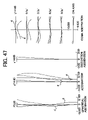
- FIG. 47 is a schematic chart for illustrating a set of aberration curvatures of the eighth example at the long focal point end when a photographing distance is 0.5 millimeters;
- FIG. 48 is a schematic chart for illustrating a set of aberration curvatures of the eighth example in a macro mode when a photographing distance is 0.3 millimeters;
- FIG. 49 is a schematic chart for illustrating a set of aberration curvatures of the eighth example in the macro mode when a photographing distance is 0.77 millimeters.
- FIGS. 50 through 57 include tables for illustrated examples of the present invention.
- a zoom lens may include the first lens band having a positive focal length, the second lens band having a negative focal length, and the third to fifth lens bands having the positive focal lengths.
- an aperture diaphragm disposed in the vicinity of the third lens band.
- the second lens band may smoothly move toward the third lens band.
- the fourth lens band may move from the fifth lens band toward a long focal point end in the vicinity of the third lens band.
- the fourth lens band may share a magnifying function together with the second lens band.
- the first, third, and fifth lens bands are fixed in case of magnification, and the second lens band (i.e., variant) is moved so as to perform the magnification.
- the fourth lens band i.e., compensating member
- the second lens band substantially bear all of the magnifying function, a moving amount of the second lens band for the magnification is large.
- a light ray valid diameter i.e., a lens external diameter
- an exemplary zoom lens of the present invention may be configured such that the fourth lens band may share the magnifying function during magnification.
- a moving amount of the second lens band is minimized, and thereby, the aperture diaphragm can be approximated by the first lens band. As a result, the light ray valid diameter of the first lens band can be minimized.
- Such a zoom lens may be preferable if it substantially meets the following inequality, wherein the reference numeral D 1W represents a distance between the first and second lens bands at a short focal point end, the reference numeral D 1T represents a distance between the first and second lens bands at a long focal point end, the reference numeral D 3W represents a distance between the third and fourth lens bands at a short focal point end, and the reference numeral D 3T represents a distance between the third and fourth lens bands at a long focal point end: ( D 3W ⁇ D 3T )/( D 1T ⁇ D 1W )>0.3
- the above-described formula may represent necessity of increase in a moving amount of the fourth lens band more than a prescribed level when magnification is performed.
- the fourth lens band does not sufficiently share the magnifying function.
- the element (D 3W ⁇ D 3T ) may indicate a moving amount of the fourth lens band when magnification from the short to long focal point ends is performed.
- the denominator (D 1T ⁇ D 1W ) may indicate a moving amount of the second lens band when magnification is performed.
- minimization of the parameter (D 3W ⁇ D 3T )/(D 1T ⁇ D 1W ) may denote minimization of the element or enlargement of the denominator.
- the minimization of the element may denote decrease in a moving amount of the fourth lens band.
- enlargement of the denominator may denote enlargement of a moving amount of the second lens band. Accordingly, a magnifying function to be shared by the fourth lens band may be minimized in any cases.
- a rate of sharing magnifying function by the fourth lens band may become larger.
- the magnifying function share rate by the fourth lens band becomes excessively large, the magnifying function share rate of the second lens band may become smaller, thereby resulting in difficulty in obtaining fair magnification. Accordingly, a limit of the parameter (D 3W ⁇ D 3T )/(D 1T ⁇ D 1W ) may be around 1.0.
- the above-described zoom lens may be novel to the extent that the fourth lens band shares a magnifying function together with the second lens band.
- the zoom lens can be a photographic zoom lens whose first lens band is arranged in an object side.
- the fourth lens band may come closest to the third lens band during its movement from the fifth lens band side toward the long focal point end in the vicinity of the third lens band for magnification at a focal point slightly before the long focal point end.
- the zoom lens can have both of functions of magnifying and compensating an image surface positional variance that accompanies the magnification at once.
- the fourth lens band smoothly moves from the fifth lens band side toward the long focal point end in the vicinity of the third lens band.
- the positional variance of an image surface may accompany the magnification performed by the smooth movement of the second and fourth lens bands.
- the positional variance may be compensated by a movement of the fifth lens band.
- the first lens band can be fixed. Such fixation may represent a stable, permanently fixed condition.
- the first lens band may preferably always be fixed. Because, the first lens band is biggest and heaviest, movement of the first lens band may be easy to impair simplicity of the mechanism and electrical power saving.
- the first lens band may become large owing to reservation of a circumference light quantity at a close range.
- the third lens band and an aperture diaphragm may be fixed.
- a shutter (not shown) is sometimes arranged at a position of the aperture diaphragm, and displacement of the shutter may unfortunately cause a mechanism to be complex. If a shutter movable configuration is employed, vibration generated when the shutter is driven may easily travel to another portion of a lens unit, and is a possible cause of image vibration.
- focusing can be performed by integrally moving the whole lens units.
- the photo-acceptance unit can be moved.
- inner focusing performed by moving one or more lens bands other than the first lens band may be employable.
- focusing can be performed by movement of the fifth lens band.
- the fifth lens band is most preferably utilized for focusing.
- the amount of movement required to adjust a focal point of an object of a prescribed distance may be smaller at the short focal point end, and larger at the long focal point end, in contrast.
- an interval between the fourth and fifth lens bands may be small when lens band moves to the short focal point end, and large when they moves to the long focal point end as similar to the above, movement of the fifth lens band for focusing may not be impaired by the fourth lens band.
- the following inequality may be preferably met by the focal length f 1 of the first lens band and the composite focal length f 12T of the first and second lens bands in order to further downsize and obtain a higher performance: ⁇ 1.4 ⁇ ( f 12T /f 1 ) ⁇ 1.0
- Such parameter (f 12T /f 1 ) may denote a magnification rate of the second lens band at the long focal point end.
- power of the first lens band is required to be strengthened (i.e., to shorten a focal length).
- the magnification rate of the second lens band at the long focal point end preferably may be set at less than ⁇ 1.
- the magnification rate of the second lens band at the long focal point end is less than ⁇ 1.4, since contribution of the fourth lens band to the magnification is weakened and the power of the second lens band should be strengthened, disadvantage may arise in aberration compensation.
- one example of zoom lens may preferably substantially meet the following inequality, wherein the reference numeral f 12W represents the composite focal length of the first and second lens bands at the short focal point end, the reference numeral f 12T represents the composite focal length of the first and second lens bands at the long focal point end, and the reference numeral f 1T represents a focal length of the whole lens units at the long focal point end, and the reference numeral f 1W represents a focal length of the whole lens units at the short focal point end: 0.4 ⁇ ( f 12T /f 12W )/( f T /f W ) ⁇ 0.7
- the element (f 12T /f 12W ) may indicate a magnification change of the second lens band.
- the denominator (f T /f W ) may indicate a magnification rate of a zoom lens as it is. If the parameter (f 12T /f 12W )/(f T /f W ) exceeds the upper limit 0.7, a magnifying function of the fourth lens band is insufficient, and the first lens band may generally be increase in size. In contrast, when the parameter (f 12T /f 12W )/(f T /f W ) lowers the lower limit 0.4, the magnifying function of the second lens band may excessively become weak and a change in an incident pupil radius at the time of zooming may become small. As a result, a variance of the F-number from the short to long focal point ends may unavoidably become large when a diameter of an aperture diaphragm is set constant.
- a method for maintaining the F-number constant by varying the aperture diaphragm diameter at the time of zooming can be employed.
- a mechanism i.e., a shutter
- less than three lenses may constitute each lens band. More than one non-spherical surface may be employed in each of the second and third lens bands. Further, more than one non-spherical surface may be employed in any one of fourth and fifth lens bands.
- each aberration has to be suppressed to an extraordinary small level.
- each lens band With less than three lenses to be relatively simple, and utilizing more than one non-spherical surface in each of the second and third lens bands and at least any one of the fourth and fifth lens bands, a high imaging performance capable of sufficiently accommodating the photo-acceptance unit can be secured.
- a zoom lens may be configured in the following manner. That is, less than three lenses may constitute the first to third lens bands and fifth lens band. In addition, four lenses may constitute the fourth lens band, and more than one non-spherical surface may be included in each of the second and third lens bands. In addition, more than one non-spherical surface may be included in any one of the fourth and fifth lens bands.
- the fifth lens band may include one lens. This may introduce an advantage that movement can be performed with small energy because the fifth lens band weighs relatively light when moved in order to perform compensation of an image surface variance and focusing.
- the aperture diaphragm may be arranged in the object side in the vicinity of the third lens band.
- An exemplary camera apparatus may employ the above-described any one of zoom lenses as a photograph use zoom lens.
- the camera apparatus may be any one of a conventional silver photographic camera, a digital camera, and a digital video camera having a function of digitizing a photographed image.
- the camera apparatus can employ a photo-acceptance unit having more than three million pixels in order to receive a light ray of an image via the zoom lens.
- the camera apparatus can be utilized in a mobile information terminal.
- the first practical example may be a type in that the fifth lens band is fixed, and the fourth lens band exerts both functions of magnifying and compensating an image surface positional variance that accompanies the magnification.
- the successive second to fifth practical examples may be types in that an image surface positional variance may be compensated by moving the fifth lens band.
- the reference numeral (f) represents a focal length of the whole lens units.
- the reference numeral (F) represents an F-number.
- the reference numeral (.) represents a half field angle.
- the reference numeral (R) represents a curvature radius (a paraxial curvature radius in a case of a non-spherical surface).
- the reference numeral (D) represents an interval of a surface including a surface of an aperture diaphragm.
- the reference numeral (Nd) represents a refraction index of a d-line.
- the reference numeral (.d) represents an abbe's number.
- the reference numeral (K) represents a circular cone constant of the non-spherical surface.
- the reference numeral A 4 is the fourth degree coefficient of a non-spherical surface.
- the reference numeral A 6 is the sixth degree coefficient of a non-spherical surface.
- the reference numeral A 8 is the eighth degree coefficient of a non-spherical surface.
- the reference numeral A 10 is the tenth degree coefficient of a non-spherical surface.
- a plurality of coordinates “X” of non-spherical surfaces whose surface numbers have asterisks (*) may be determined from the following universally known formula by substituting values of the above-described reference numerals K, A 4 , A 6 , A 8 and A 10 .
- Such a reference numeral “X” represents a coordinate of a surface of the non-spherical surface in the optical axis direction at each height of the surface
- the reference numeral “C” represents an inverse number of a paraxial curvature radius (i.e., a paraxial curvature)
- Such a “surface number” may be of a number counted starting from the object nearest side surface.
- a unit of a quantum having a length dimension may be millimeter.
- a plurality of lenses having prescribed properties may be employed as listed on the table 1 A ( FIG. 50 ).
- Each of the non-spherical surfaces of the fifth, seventh, twelfth, fourteenth, and nineteenth surfaces may be defined by predetermined values listed on the table 1 B. Further, a plurality of intervals A, B, C, and D may also be listed on the table 1 C. In addition, a plurality of numerical values listed on the table 1 D may be assigned to parameters of conditional expressions in this practical example.
- both a variable distance and a focal length when magnification from the short to long focal point ends is performed and the fourth lens band comes closest to the third lens band may be listed on the table 1 E.
- FIG. 2 A lens arrangement of the first practical example may be illustrated in FIG. 2 , wherein the reference numerals I, II, III, IV and V may represent the first, second, third, fourth and fifth lens bands.
- the reference numeral “S” may represent an aperture diaphragm, and that of FL may represent a variety of lens filters. These may be similar in subsequent drawings.
- a plurality of properties of lenses may be listed in the table 2 A.
- Each of the non-spherical surfaces of the fifth, seventh, twelfth, fourteenth, and nineteenth surfaces in this example may be defined by predetermined values as listed on the table 2 B.
- a plurality of intervals A, B, C, and D in this example may be listed on the table 2 C.
- a plurality of values assigned to parameters of conditional expressions may be listed on the table 2 D.
- a lens arrangement of the second practical example may be illustrated in FIG. 3 .
- a plurality of lens properties of this example may be listed on the table 3 A.
- Each of the non-spherical surfaces of the fifth, seventh, twelfth, fourteenth, and nineteenth surfaces may be defined by predetermined values as listed on the table 3 B.
- a plurality of intervals A, B, C, and in this practical example may be listed on the table 3 C.
- a plurality of numerical values assigned to parameters of conditional expressions in this practical example may be listed on the table 3 D.
- FIG. 4 a lens arrangement of the third practical example may be illustrated in FIG. 4 .
- Each of the non-spherical surfaces of the fifth, seventh, eleventh, thirteenth, fourteenth, and twenty-first surfaces may be defined by predetermined values listed on the table 4 B.
- a plurality of intervals A, B, C, and D may be listed on the table 4 C.
- a plurality of numerical values assigned to parameters of conditional expressions in this practical example may be listed on the table 4 D.
- a lens arrangement of the third practical example may be illustrated in FIG. 5 .
- Each of the non-spherical surfaces of the fifth, seventh, twelfth, fourteenth, fifteenth, and twenty-second surfaces may be defined by predetermined values listed on the table 5 B.
- a plurality of intervals A, B, C, and D may be listed on the table 5 C.
- a plurality of numerical values assigned to parameters of conditional expressions in this practical example may be listed on the table 5 D.
- a lens arrangement of the fifth practical example may be illustrated in FIG. 6 .
- a set of aberration curvatures at the short focal point end, the middle focal length, and the long focal point end of the first practical example may be illustrated in FIGS. 7 to 9 one by one.
- plural sets of aberration curvatures of the second to fifth practical examples may be illustrated in FIGS. 10 to 12 , 13 to 15 , 16 to 18 , and 19 to 21 , respectively, one by one.
- a dotted line in the spherical surface aberration diagram may represent a sine condition.
- a rigid line in the diagram of the astigmatism may represent sagittal, and a dotted line may represent meridional.
- reference numerals (g) and (d) may represent a (g)-line and a (d)-line, respectively.
- each of the practical examples may have an extremely fair performance, and is capable of accommodating a digital camera or the like employing a photo acceptance unit having more than three million pixels.
- any one of zoom lenses of from the first to fifth practical examples there may be provided with the first lend band having a positive focal length, the second lens band II. having a negative focal length, the third to fifth lens bands III, IV., and V. having positive focal lengths, and the aperture diaphragm “S” disposed in the vicinity of the third lens band III.
- the second lens band may smoothly move toward the third lens band.
- the fourth lens band may move from the fifth lens band side toward the long focal point end in the vicinity of the third lens band.
- the fourth lens band may take partial charge of the magnifying function together with the second lens band.
- an exemplary zoom lens may be designed so that the following inequality may be valid, wherein a distance between the first and second lens bands at the short focal point end is D 1W , that between the first and second lens bands at the long focal point end is D 1T , that between the third and fourth lens bands at the short focal point end is D 3W , and that between the third and fourth lens bands at the long focal point end is D 3T : ( D 3W ⁇ D 3T )/( D 1T ⁇ D 1W )>0.3
- the exemplary zoom lens may be for photographic use with the first lens band (I) sides facing an object side.
- the first exemplary zoom lens may be configured such that the fourth lens band moves from the fifth lens band side toward the long focal point end in the vicinity of the third lens band, and comes closest to the third lens band at a focal point slightly before the long focal point end when magnification from the short to long focal point ends is performed.
- the second to fourth exemplary zoom lenses may be configured such that the fourth lens band smoothly moves from the fifth lens band side toward the long focal point end in the vicinity of the third lens band, and the movement of the fifth lens band compensates a positional variance of an image surface which is caused by the smooth movement of the second and fourth lens bands when magnification from the short to long focal point ends is performed.
- the zoom lenses of the first to fifth examples may be configured such that the first and third lens bands and the aperture diaphragm may be fixation types, and focusing is performed by movement of the fifth lens band.
- each of these exemplary zoom lens may substantially meet the following inequality wherein reference numerals f 1 and f 12T may be a focal length of the first lens band and a combination focal length of the first and second lens bands at the long focal point end: ⁇ 1.4 ⁇ ( f 12T /f 1 ) ⁇ 1.0
- reference numerals f 12W and f 12T are combination focal lengths of the first and second lens bands at the short and long focal point ends, respectively.
- reference numerals f T and f W are focal lengths of the whole lens units at the long and short focal point ends, respectively: 0.4 ⁇ ( f 12T /f 12W )/( f T /f W ) ⁇ 0.7
- the zoom lenses of from the first to third examples may be configured such that each of the lens bands is formed by less than three lenses, more than one non-spherical surface may be included in each of the second and third lens bands, and more than one non-spherical surface may be included in one of the fourth and fifth bands.
- the zoom lenses of the fourth and fifth examples may be configured such that less than three lenses constitute the first to third and fifth bands.
- four lenses may constitute the fourth lens band, more than one non-spherical surface may be included in each of the second and third lens bands, and more than one non-spherical surface may be included in one of the fourth and fifth bands.
- each of the examples may be configured such that one lens constitutes the fifth lens band, and the aperture diaphragm “S” may be arranged in the object side of the third lens band III.
- This camera may be a mobile information terminal. 10
- the mobile information terminal 10 may include a photographing lens 11 and is configured to read an image of a photographing object with a photo-acceptance unit (i.e., an area sensor) 15 .
- a photo-acceptance unit i.e., an area sensor
- the above-described any one set of exemplary zoom lenses may be utilized.
- An output of the photo-acceptance unit 15 may be input to a signal processing apparatus 17 , and then converted into digital information by the signal processing apparatus 17 controlled by a central processor 21 .
- the camera apparatus of FIGS. 22A , 22 B and 22 C may function to convert a photographing image into digital information.
- More than three million pixels may be used for its photo-acceptance unit 15 so as to receive an image via the photographing lens (i.e., zoom lens) 11 .
- the photographing lens i.e., zoom lens
- the image information may receive prescribed image processing in the image processing apparatus 19 under control of the central processor 21 after being converted into the digital information by the signal processing apparatus 17 .
- image information may be capable of selectively being displayed on a liquid crystal monitor 23 or stored in a semiconductor memory 27 . Otherwise, it can be transferred outside via a communication card or the like 25 .
- FIG. 22A is a front side view illustrating a mobile information terminal in use.
- FIG. 22B is a rear side view of the mobile information terminal.
- the camera apparatus 10 as the mobile information terminal may have a flat rectangular box shape, and is handled selectively standing with its liquid crystal monitor 23 being open. Simultaneously, a display of the liquid crystal monitor 23 may face a user (i.e., a photographer side). In addition, the object lens 11 of the photographic lens (i.e., the zoom lens 11 ) may face a photographic object.
- a switch SW When a photograph is taken, a switch SW is turned ON, and a photograph mode may then be selected using an operation button 36 . A selected mode may be displayed on a liquid crystal panel 32 . Then, while peeping in through an ocular lens of a finder 13 illustrated in FIG. 22B , a photographer may select a zoom ratio through an operation of a zoom lever 38 . Focusing may automatically be performed by movement of the fifth lens band.
- photographing may be performed.
- the above-described information digitization may subsequently be performed.
- To display and review the photographed image on the liquid crystal monitor 23 such a request may be selected through the operation button 36 .
- desired recordation of information may be performed through an operation of the operation button 36 in the semiconductor memory (i.e., memory card) 27 with it being inserted into a dedicated throttle of the camera body.
- the semiconductor memory i.e., memory card
- transmission may be performed through an operation of the operation button 36 with the communication card 25 being inserted into a dedicated throttle of the camera body.
- image information transferred from outside via the communication card 25 can optionally be displayed on the liquid crystal monitor 23 .
- a zoom lens of this invention may include the first lens band I having a positive focal length, the second lens band II having a negative focal length, and the third III, fourth IV, and fifth V lens bands having positive focal lengths arranged from an object side toward an image surface as illustrated in FIG. 23 .
- An aperture diaphragm “S” may also be arranged in the vicinity of the third lens band.
- FIG. 23A may illustrate a lens band arrangement of a short focal point end (i.e., a wide-angle end).
- FIG. 23A may also illustrate a lens band arrangement of a telescopic end.
- FIG. 23B may illustrate a lens band arrangement of a macro mode.
- the second lens band II may smoothly move toward the third lens band III when magnification from the short to long focal point end ( FIG. 23A ) is performed.
- the fourth lens band IV may move from the fifth lens band V side toward the long focal point end in the vicinity of the third lens band III.
- the fourth lens band IV may bear part of a magnifying function together with the second lens band II.
- the fifth lens band IV may perform focusing by its movement both in the typical photographing region and macro mode.
- Such a typical photographing region may represent the entire photographing region in that the focusing is possible at an optional zoom position between the short and long focal point ends including these ends. Simply in other words, it may be a photographing region in that zoom photographing is available.
- the macro mode may be a mode that is set outside the typical photographing region and enables lenses to focus at a distance shorter than that of the zoom photographing.
- a lens band arrangement in the macro mode may be different from that of the lens band for zooming between the short to long focal point ends as illustrated in FIG. 23B . Specifically, lens band movement for zooming can not realize the lens band arrangement for the macro mode.
- the zoom lens whose first to fifth lens bands having power allocation such as positive, negative, positive, positive, and positive
- the first, third, and fifth lens bands are fixed in case of performing magnification, and the second lens band (variant) is moved so as to perform the magnification.
- the fourth lens band (compensating member) is moved so as to compensate a positional variance of an image surface which accompanies the magnification.
- the second lens band substantially bears all of the magnifying function, a moving amount of the second lens band for the magnification is large.
- the first lens band largely steps away from an aperture diaphragm, a light ray valid diameter (i.e., a lens external diameter) of the first lens band becomes large when realizing a wide angle.
- an exemplary zoom lens may be configured such that the fourth lens band also shares the magnifying function when the magnification is performed.
- the aperture diaphragm may be approximated by the first lens band by minimizing the moving amount of the second lens band.
- the light ray valid diameter of the first lens band may be minimized.
- the focusing in the typical photographing region may be performed by the movement of the fifth lens band.
- an interval between the fourth and fifth lens bands should or may be better to be short.
- focusing at a distance shorter than the typical photographing region may be enabled in the macro mode by arranging the second and fourth lens bands in a positional relation different from that arranged when zooming is performed.
- focusing up to a distance (the shortest photographing distance in a macro mode) shorter than the shortest photographing distance for the typical photographing region is required in the macro mode.
- the fifth lens band may be selected as a movement objective as similar to a case when focusing in the typical photographing region.
- only one lens band may be enough to be driven by a focus signal passed from a distance measurement device or the like (not shown), thereby capable of simplifying a focusing mechanism.
- a rear lens band illustrated in FIG. 23 may be a variety of filters.
- the fourth lens band in a macro mode may preferably be positioned at the fourth lens band at the long focal point end.
- the fourth lens band may necessarily become increase in size.
- Such a fourth lens band may come closest to the aperture diaphragm in the vicinity of the long focal point end in the zoom photographing, and amount of the cut off by the fourth lens band may be least at that time.
- the cut off can be suppressed as much as possible even performing focusing to a short distance by moving the fifth lens band.
- the shortage of the circumferential light ray quantity and the increase in size of the fourth lens band can be avoided.
- the second lens band in a macro mode may preferably be positioned nearer to an image surface than the second lens band at the short focal point end.
- a cause of easier generation of the large negative distortion aberration at the short focal point end may be that the second lens band having a negative power comes closest to the first lens band, and a negative strong power may arise in the distance from the object side of the aperture diaphragm.
- the second lens band approximates the first lens band, negative large distortion aberration easily arises in the macro mode. Then, the negative distortion aberration may be suppressed to be small in the macro mode like in another exemplary zoom lens by alienating the second lens band from the first lens bands.
- both of the second and fourth lens bands in a macro mode may preferably be arranged such that the fourth lens band is positioned close to the fourth lens band at the long focal point end, and the second lens band is positioned closer to the image surface than the second lens band at the short focal point end.
- a focal length in the macro mode may become longer than that at a short focal point end, and shorter than that at the long focal point end during zooming.
- the first lens band of the zoom lens is immobile with regard to an image surface in one embodiment. It is not new itself to fix the first lens band at the times of zooming and focusing. However, the first lens band may be fixed because the first lens band is unnecessary to be moved even when a typical photographing region is switched to a macro mode in the zoom lens according to the present invention. In addition, if the first lens band having heaviest weight is always fixed with regard to the image surface, a number of actuators used for moving a lens band and amount of torque does not need to be increased. As a result, such a construction may be advantageous in view of cost and power consumption saving.
- the third lens band and the aperture diaphragm may be preferably immobile with regard to the image surface in one example of a zoom lens.
- a shutter sometimes is arranged at the position of the aperture diaphragm, and movement of the shutter causes undesirable result such as complexity of its mechanism.
- the shutter causes vibration when it is driven, and if a configuration enabling the shutter to move is employed, the vibration may easily travel to another parts of the lens unit, thereby being possible cause of image vibration. Then, problems such as mechanical complexity and image vibration can efficiently be avoided if both of the third lens band and aperture diaphragm are fixed like the zoom lens as stated earlier.
- the first and third lens bands as well as the aperture diaphragm may be immobile with regard to the image surface.
- the following inequality may be valid in an exemplary zoom lens, wherein distances between the first and second lens bands at short and long focal point ends and in a macro mode are L 1W , L 1T , and L 1C , respectively: 0.15 ⁇ ( L 1C ⁇ L 1W )/( L 1T ⁇ L 1W ) ⁇ 0.40
- the lower limit of the above-described inequality may be a condition for suppressing a large negative distortion aberration in a macro mode to be small. Thus, if the lower limit is exceeded, a negative distortion aberration that accompanies focusing may be large. In contrast, if the higher limit is exceeded, focusing toward a sufficiently short distance may be difficult.
- distances between the third and fourth lens bands at short and long focal point ends and in a macro mode are L 3W , L 3T , and L 3C , respectively: 0.25 ⁇ ( L 3C ⁇ L 3W )/( L 3W ⁇ L 3T ) ⁇ 0.50
- the upper limit of the above-described inequality may relief cutting off of the circumferential light flux in the macro mode of the zoom lens. If the upper limit is exceeded, sufficient avoidance of the cutting off may be difficult to be achieved, and a moving amount of the fifth lens band for focusing may be limited. In contrast, if the lower limit of the above-described inequality is exceeded, focusing to a sufficiently short distance may be difficult.
- distances L 1W , L 1T , and L 1C between the first and second lens bands, as well as L 3W , L 3T , and L 3C between the third and fourth lens bands may satisfy the above-described two inequalities.
- zoom lens may preferably substantially meet the following inequality, wherein the reference numeral D 1W represents a distance between the first and second lens bands at a short focal point end, the reference numeral D 1T represents a distance between the first and second lens bands at a long focal point end, the reference numeral D 3W represents a distance between the third and fourth lens bands at a short focal point end, and the reference numeral D 3T represents a distance between the third and fourth lens bands at a long focal point end: ( D 3W ⁇ D 3T )/( D 1T ⁇ D 1W )>0.3
- the above-described formula may represent necessity of increasing in a moving amount of the fourth lens band more than a prescribed level when magnification is performed. Specifically, if the parameter (D 3W ⁇ D 3T )/(D 1T ⁇ D 1W ) becomes smaller than the lower limit 0.3, there may exist a probability that the fourth lens band does not sufficiently share the magnifying function. For example, if supposing a case in which the third lens band is fixed, the element (D 3W ⁇ D 3T ) may indicate a moving amount of the fourth lens band when magnification from the short to long focal point ends is performed.
- the denominator (D 1T ⁇ D 1W ) may indicate a moving amount of the second lens band when magnification is performed.
- minimization of the parameter (D 3W ⁇ D 3T )/(D 1T ⁇ D 1W ) becomes small may denote minimization of the element, or enlargement of the denominator.
- the minimization of the element may denote decrease in a moving amount of the fourth lens band.
- enlargement of the denominator may denote enlargement of a moving amount of the second lens band. Accordingly, a magnifying function to be shared by the fourth lens band may be minimized in any cases.
- the rate of sharing magnifying function of the fourth lens band may become larger.
- the magnifying function share rate of the fourth lens band becomes excessively large, the magnifying function share rate of the second lens band may become smaller, thereby resulting in difficulty in obtaining fair magnification. Accordingly, a limit of the parameter (D 3W ⁇ D 3T )/(D 1T ⁇ D 1W ) may be around 1.0.
- the following inequality may be preferably met by the focal length f, of the first lens band, and the composite focal length f 12T of the first and second lens bands in order to further downsize and obtain a higher performance: ⁇ 1.4 ⁇ ( f 12T /f 1 ) ⁇ 1.0
- Such parameter (f 12T /f 1 ) may denote a magnification rate of the second lens band at the long focal point end.
- power of the first lens band is strengthened (i.e., to shorten a focal length).
- a magnification rate of the second lens band at the long focal point end may be set at less than ⁇ 1.
- magnification rate of the second lens band at the long focal point end is less than ⁇ 1.4, since contribution of the fourth lens band to the magnification is weakened and the power of the second lens band should be strengthened, disadvantage may arise in aberration compensation.
- the fourth lens band smoothly moves from the fifth lens band side toward the long focal point end in the vicinity of the third lens band.
- a positional variance of an image surface which accompanies the magnification performed by the smooth movement of the second and fourth lens bands may be compensated by a movement of the fifth lens band.
- the fourth lens band may come closest to the third lens band during its movement from the fifth lens band side toward the long focal point end in the vicinity of the third lens band for magnification at a focal point slightly before the long focal point end. If operated in such a manner, it is possible to enable the fourth lens band to have a function of compensating a positional variance of an image surface accompanying magnification beside a magnifying function.
- one example of the zoom lens may be configured such that less than three lenses constitute the first to third and the fifth lens bands.
- Four lens may constitute the fourth lens band.
- At least one non-spherical surface may be employed in the second, third, and fifth lens bands, and two or more non-spherical surfaces may be employed in the fourth lens band.
- the fifth lens band of an exemplary zoom lens may include one lens. This may bring an advantage that movement can be performed with small energy because the fifth lens band weighs light when moved in order to perform compensation of an image surface variance and focusing.
- one positive lens may constitute the third lens band, and the aperture diaphragm may be arranged in the object side of the third lens band.
- the third lens band may simply be configured with it being included in a shutter unit.
- an exemplary camera apparatus may employ the above-described any one of zoom lenses for photographic use.
- the camera apparatus may by any one of a conventional silver photographic camera, a digital camera, and a digital video camera having a function of digitizing a photographed image.
- the above-described camera apparatus can employ a photo-acceptance unit having more than three million pixels in order to receive a light ray of an image via the zoom lens.
- the camera apparatus can be utilized in a mobile information terminal.
- a plurality of practical examples of a zoom lens is now described with reference to tables 6 A, 6 B, 6 C, and 6 D, wherein it is premised that a set of aberrations of each example is sufficiently compensated and thereby capable of accommodating a photo acceptance unit having more than three million pixels.
- the following first to third examples may be types in which a positional variation of an image surface which accompanies magnification of second and fourth band may be compensated by movement of the fifth lens band.
- the reference numeral (f) represents a focal length of the whole lens units.
- the reference numeral (F) represents an F-number.
- the reference numeral (.) represents a half field angle.
- the reference numeral (R) represents a curvature radius including a paraxial curvature radius in a case of a non-spherical surface.
- the reference numeral (D) represents an interval of a surface including a surface of an aperture diaphragm.
- the reference numeral (Nd) represents a refraction index of a d-line.
- the reference numeral (.d) represents an abbe's number.
- the reference numeral (K) represents a circular cone constant of the non-spherical surface.
- the reference numeral A 4 is the fourth degree coefficient of a non-spherical surface.
- the reference numeral A 6 is the sixth degree coefficient of a non-spherical surface.
- the reference numeral A 8 is the eighth degree coefficient of a non-spherical surface.
- the reference numeral A 10 is the tenth degree coefficient of a non-spherical surface.
- a plurality of non-spherical surfaces whose surface numbers have asterisks (*) may be determined from the following universally known formula by substituting values of the above-described reference numerals K, A 4 , A 6 , A 8 and A 10 .
- Such a reference numeral “X” may represent a coordinate of the non-spherical surface in the optical axis direction at each height from the original point
- the reference numeral “C” represents an inverse number of a paraxial curvature radius (i.e., a paraxial curvature)
- Such a “surface number” may be of a number counted from an object nearest surface.
- a unit of a quantum having a length dimension may be millimeter.
- the first practical example of properties of the entire lens arrangement constituting a zoom lens may be listed on the table 6 A.
- non-spherical surfaces whose surface numbers have asterisks are may be defined by predetermined values listed on the table 6 B.
- variable intervals during the typical photographing and in a macro mode, and conditional expression values are listed on the tables 6 C and 6 D.
- a plurality of properties of the entire lenses constituting a zoom lens of the second practical example may be listed on the table 7 A.
- a plurality of non-spherical surfaces whose surface numbers have asterisks may be defined by predetermined values listed on the table 7 B.
- a plurality of intervals A, B, C, and D during the typical photographing and in a macro mode, and conditional expression values are listed on the tables 7 C and 7 D.
- a plurality of properties of the entire lenses of the third practical example may be listed on the table 8 A.
- a plurality of non-spherical surfaces whose surface numbers have asterisks may be defined by predetermined values listed on the table 8 B.
- a plurality of intervals A, B, C, and D during the typical photographing and in a macro mode, and conditional expression values may be listed on the tables 8 C and 8 D.
- FIGS. 4 to 6 A plurality of aberration curvatures of the first example at short, middle, and long focal point ends when a photographing distance is infinite may be illustrated from FIGS. 4 to 6 one after another.
- FIG. 7 illustrates a set of aberration curvatures of the first example at the short focal point end when the photographing distance is 0.3 meters.
- FIG. 8 illustrates a set of aberration curvatures at the middle focal length when the photographing distance is 0.4 meters.
- FIG. 9 illustrates a set of aberration curvatures at the long focal point end when the photographing distance is 0.5 meters.
- FIG. 10 illustrates a set of aberration curvatures when the photographing distance is 0.3 meters in a macro mode.
- FIG. 11 also illustrates a set of aberration curvatures in a macro mode when the photographing distance is 0.77 meters.
- a set of aberration curvatures of the second example at short, middle, and long focal point ends when a photograph distance is infinite may be illustrated from FIGS. 12 to 14 one after another.
- FIG. 15 illustrates a set of aberration curvatures of the second example at the short focal point end when the photographing distance is 0.3 meters.
- FIG. 16 also illustrates a set of aberration curvatures at the middle focal length when the photographing distance is 0.4 meters.
- FIG. 17 illustrates a set of aberration curvatures at the long focal point end when the photographing distance is 0.5 meters.
- FIG. 18 also illustrates a set of aberration curvatures when the photographing distance is 0.3 meters in a macro mode.
- FIG. 19 also illustrates a set of aberration curvatures when the photographing distance is 0.77 meters in a macro mode.
- a plurality of aberration curvatures of the second example at short, middle, and long focal point ends when a distance is infinite may be illustrated from FIGS. 20 to 22 one after another.
- FIG. 23 illustrates a set of aberration curvatures of the third example at the short focal point end when the photographing distance is 0.3 meters.
- FIG. 24 also illustrates a set of aberration curvatures of the third example at a middle focal length when the photographing distance is 0.4 meters.
- FIG. 25 also illustrates a set of aberration curvatures at the long focal point end when the photographing distance is 0.5 meters.
- FIG. 26 also illustrates a set of aberration curvatures of the third example when the photographing distance is 0.3 meters in a macro mode.
- FIG. 27 also illustrates a set of aberration curvatures when the photographing distance is 0.77 meters in a macro mode.
- a dotted line in the spherical surface aberration may represent a sine condition.
- a rigid line in the diagram of the astigmatism may represent sagittal, and a dotted line may represent meridional.
- reference numerals (g) and (d) may represent a (g)-line and a (d)-line, respectively.
- each of the examples may have an extremely fair performance, and is capable of accommodating a digital camera or the like employing a photo acceptance unit having more than three million pixels.
- the first lens band I having a positive focal length, the second lens band II having a negative focal length, and the third to fifth lens bands III, IV, and V having the positive focal lengths may be arranged toward an image surface from the object.
- an aperture diaphragm “S” may be disposed in the vicinity of the third lens band III.
- the second lens band II may smoothly move toward the third lens band III.
- the fourth lens band IV may move from the fifth lens band V side toward a long focal point end in the vicinity of the third lens band III.
- the fourth lens band IV may share a magnifying function together with the second lens band II.
- a macro mode enabling focusing outside at a shorter distance than a typical photographing region for zooming may be employed.
- the focusing may be performed by movement of the fifth lens band V both in the typical photographing region and in the macro mode.
- the fourth lens band III in a macro mode may be positioned close to the fourth lens band IV at the long focal point end.
- the second lens band II in a macro mode may be positioned closer to the image surface than the second lens band II at the short focal point end.
- first lens band I may be immobile with regard to the image surface.
- the third lens band III and the aperture diaphragm “S” may also be immobile with regard to the image surface.
- the following inequality may be satisfied, if distances between the first and second lens bands at short and long focal point ends and in a macro mode are L 1W , L 1T , and L 1C , respectively: 0.15 ⁇ ( L 1C ⁇ L 1W )/( L 1T ⁇ L 1w ) ⁇ 0.40
- the following inequality may also be satisfied, if a plurality of distances between the third and fourth lens bands at short and long focal point ends and in a macro mode are L 3W , L 3T , and L 3C , respectively: 0.25 ⁇ ( L 3C ⁇ L 3W )/( L 3W ⁇ L 3T ) ⁇ 0.50
- the following inequality may preferably be satisfied, wherein distances between the first and second lens bands at the short and long focal point ends are D 1W and D 1T , and those between the third and fourth lens bands at the short and long focal point ends are D 3W and D 3T : ( D 3W ⁇ D 3T )/( D 1T ⁇ D 1W )>0.3
- the following inequality may preferably be satisfied if f 1 and f 12T may be focal lengths of the first lens band and a combination focal length of the first and second lens bands at the long focal point end, respectively: ⁇ 1.4 ⁇ ( f 12T /f 1 ) ⁇ 1.0
- the fourth lens band IV may smoothly move toward a long focal point end in the vicinity of the third lens band III from the fifth lens band V side.
- a positional variance of an image surface which is caused by the magnification performed by the smooth movement of the second and fourth lens bands may be compensated by the movement of the fifth lens band.
- the first to third and fifth lens bands may be formed by less than three lenses.
- Four lens may constitute the fourth lens band.
- More than one non-spherical surface may be included in each of the second, third, and fifth lens bands.
- more than two non-spherical surfaces may be included in the fourth lens band.
- one lens may constitute the fifth lens band V.
- the third lens band III may be constituted by a positive lens.
- the aperture diaphragm “S” may be arranged in the object side of the third lens band III.
- zoom lenses Any of the above-described zoom lenses may be employed in the earlier described camera apparatus.
- the mechanisms and processes set forth in the present invention may be implemented using one or more conventional general purpose microprocessors and/or signal processors programmed according to the teachings in the present specification as will be appreciated by those skilled in the relevant arts.
- Appropriate software coding can readily be prepared by skilled programmers based on the teachings of the present disclosure, as will also be apparent to those skilled in the relevant arts.
- the present invention also may be implemented by the preparation of application-specific integrated circuits by interconnecting an appropriate network of conventional component circuits or by a combination thereof with one or more conventional general purpose microprocessors and/or signal processors programmed accordingly.
Abstract
Description
(D 3W −D 3T)/(D 1T −D 1W)>0.3
−1.4<(f 12T /f 1)<−1.0
0.4<(f 12T /f 12W)/(f T /f W)<0.7
0.15<(L 1C −L 1W)/(L 1T −L 1W)<0.40
0.25<(L 3C −L 3W)/(L 3W −L 3T)<0.50
0.15<(L 1C −L 1W)/(L 1T −L 1W)<0.40
0.25<(L 3C −L 3W)/(L 3W −L 3T)<0.50
(D 3W −D 3T)/(D 1T −D 1W)>0.3
−1.4<(f 12T /f 1)<1.0
(D 3W −D 3T)/(D 1T −D 1W)>0.3
The above-described formula may represent necessity of increase in a moving amount of the fourth lens band more than a prescribed level when magnification is performed. Specifically, if the parameter (D3W−D3T)/(D1T−D1W) becomes smaller than the lower limit 0.3, there may be a probability that the fourth lens band does not sufficiently share the magnifying function. For example, if supposing a case in which the third lens band is fixed, the element (D3W−D3T) may indicate a moving amount of the fourth lens band when magnification from the short to long focal point ends is performed. Similarly, the denominator (D1T−D1W) may indicate a moving amount of the second lens band when magnification is performed.
−1.4<(f 12T /f 1)<−1.0
0.4<(f 12T /f 12W)/(f T /f W)<0.7
The element (f12T/f12W) may indicate a magnification change of the second lens band. The denominator (fT/fW) may indicate a magnification rate of a zoom lens as it is. If the parameter (f12T/f12W)/(fT/fW) exceeds the upper limit 0.7, a magnifying function of the fourth lens band is insufficient, and the first lens band may generally be increase in size. In contrast, when the parameter (f12T/f12W)/(fT/fW) lowers the lower limit 0.4, the magnifying function of the second lens band may excessively become weak and a change in an incident pupil radius at the time of zooming may become small. As a result, a variance of the F-number from the short to long focal point ends may unavoidably become large when a diameter of an aperture diaphragm is set constant.
X=CH 2/0.1+.(1−(1+k)C 2 H 2).+A 4 .H 4 +A 6 .H 6 +A 8 .H 8 +A 10 .H 10
Then, a shape may be defined by giving R(=1/C), K, A4, A6, A8 and A10. Such a “surface number” may be of a number counted starting from the object nearest side surface. A unit of a quantum having a length dimension may be millimeter.
(D 3W −D 3T)/(D 1T −D 1W)>0.3
−1.4<(f 12T /f 1)<−1.0
0.4<(f 12T /f 12W)/(f T /f W)<0.7
0.15<(L 1C −L 1W)/(L 1T −L 1W)<0.40
0.25<(L 3C −L 3W)/(L 3W −L 3T)<0.50
(D 3W −D 3T)/(D 1T −D 1W)>0.3
−1.4<(f 12T /f 1)<−1.0
X=CH 2/0.1+.(1−(1+k)C 2 H 2).+A 4 .H 4 +A 6 .H 6 +A 8 .H 8 +A 10 .H 10
Then, a shape may be defined by giving R(=1/C), K, A4, A6, A8 and A10. Such a “surface number” may be of a number counted from an object nearest surface. A unit of a quantum having a length dimension may be millimeter.
0.15<(L 1C −L 1W)/(L 1T −L 1w)<0.40
In addition, the following inequality may also be satisfied, if a plurality of distances between the third and fourth lens bands at short and long focal point ends and in a macro mode are L3W , L3T , and L3C , respectively:
0.25<(L 3C −L 3W)/(L 3W −L 3T)<0.50
(D 3W −D 3T)/(D 1T −D 1W)>0.3
In addition, the following inequality may preferably be satisfied if f1 and f12T may be focal lengths of the first lens band and a combination focal length of the first and second lens bands at the long focal point end, respectively:
−1.4<(f 12T /f 1)<−1.0
Claims (38)
(D3W−D3T)/(D1T−D1W)>0.3.
−1.4<(f 12T /f 1)<−1.0.
0.4<(f 12T /f 12W)/(f T /f W)<0.7.
0.15<(L 1C −L 1W)/(L 1T −L 1W)<0.40.
0.25<(L 3C −L 3W)/(L 3W −L 3T)<0.50.
0.15<(L 1C −L 1W)/(L 1T −L 1W)<0.40
0.25<(L 3C −L 3W)/(L 3W −L 3T)<0.50.
(D3W−D3T)/(D1T−D1W)>0.3.
(D3W−D3T)/(D1T−D1W)>0.3.
Priority Applications (2)
| Application Number | Priority Date | Filing Date | Title |
|---|---|---|---|
| US10/866,301 US7379249B2 (en) | 2000-11-20 | 2004-06-14 | Downsize, high performance, and wide range magnification zoom lens and camera apparatus |
| US12/149,241 US7679835B2 (en) | 2000-11-20 | 2008-04-29 | Downsize, high performance, and wide range magnification zoom lens and camera apparatus |
Applications Claiming Priority (6)
| Application Number | Priority Date | Filing Date | Title |
|---|---|---|---|
| JP2000-352498 | 2000-11-20 | ||
| JP2000352498A JP4395255B2 (en) | 2000-11-20 | 2000-11-20 | Zoom lens and camera device |
| JP2001-037445 | 2001-02-14 | ||
| JP2001037445A JP3973844B2 (en) | 2001-02-14 | 2001-02-14 | Zoom lens and camera device |
| US09/988,793 US7038858B2 (en) | 2000-11-20 | 2001-11-20 | Downsize, high performance, and wide range magnification zoom lens and camera apparatus |
| US10/866,301 US7379249B2 (en) | 2000-11-20 | 2004-06-14 | Downsize, high performance, and wide range magnification zoom lens and camera apparatus |
Related Parent Applications (1)
| Application Number | Title | Priority Date | Filing Date |
|---|---|---|---|
| US09/988,793 Continuation US7038858B2 (en) | 2000-11-20 | 2001-11-20 | Downsize, high performance, and wide range magnification zoom lens and camera apparatus |
Related Child Applications (1)
| Application Number | Title | Priority Date | Filing Date |
|---|---|---|---|
| US12/149,241 Continuation US7679835B2 (en) | 2000-11-20 | 2008-04-29 | Downsize, high performance, and wide range magnification zoom lens and camera apparatus |
Publications (2)
| Publication Number | Publication Date |
|---|---|
| US20050270663A1 US20050270663A1 (en) | 2005-12-08 |
| US7379249B2 true US7379249B2 (en) | 2008-05-27 |
Family
ID=26604272
Family Applications (3)
| Application Number | Title | Priority Date | Filing Date |
|---|---|---|---|
| US09/988,793 Expired - Lifetime US7038858B2 (en) | 2000-11-20 | 2001-11-20 | Downsize, high performance, and wide range magnification zoom lens and camera apparatus |
| US10/866,301 Expired - Fee Related US7379249B2 (en) | 2000-11-20 | 2004-06-14 | Downsize, high performance, and wide range magnification zoom lens and camera apparatus |
| US12/149,241 Expired - Lifetime US7679835B2 (en) | 2000-11-20 | 2008-04-29 | Downsize, high performance, and wide range magnification zoom lens and camera apparatus |
Family Applications Before (1)
| Application Number | Title | Priority Date | Filing Date |
|---|---|---|---|
| US09/988,793 Expired - Lifetime US7038858B2 (en) | 2000-11-20 | 2001-11-20 | Downsize, high performance, and wide range magnification zoom lens and camera apparatus |
Family Applications After (1)
| Application Number | Title | Priority Date | Filing Date |
|---|---|---|---|
| US12/149,241 Expired - Lifetime US7679835B2 (en) | 2000-11-20 | 2008-04-29 | Downsize, high performance, and wide range magnification zoom lens and camera apparatus |
Country Status (1)
| Country | Link |
|---|---|
| US (3) | US7038858B2 (en) |
Cited By (7)
| Publication number | Priority date | Publication date | Assignee | Title |
|---|---|---|---|---|
| US20090080088A1 (en) * | 2007-09-25 | 2009-03-26 | Kazuyasu Ohashi | Zoom lens camera and personal digital assistant device |
| US20100007967A1 (en) * | 2008-07-08 | 2010-01-14 | Kazuyasu Ohashi | Zoom lens unit, imaging apparatus and portable information terminal device |
| US20100027136A1 (en) * | 2008-08-02 | 2010-02-04 | Kazuyasu Ohashi | Image forming lens, camera and portable information terminal |
| US20100271710A1 (en) * | 2009-04-24 | 2010-10-28 | Kazuyasu Ohashi | Zoom lens unit, imaging device and portable information terminal device |
| US8054560B2 (en) | 2010-03-30 | 2011-11-08 | A-Optronics Technology Inc. | Zoom lens |
| US8599500B2 (en) | 2011-02-18 | 2013-12-03 | Ricoh Company, Ltd. | Imaging lens, camera and personal digital assistant |
| US20150244907A1 (en) * | 2010-12-10 | 2015-08-27 | Olympus Imaging Corp. | Imaging apparatus and optical system used for imaging apparatus |
Families Citing this family (28)
| Publication number | Priority date | Publication date | Assignee | Title |
|---|---|---|---|---|
| US6771433B2 (en) * | 2001-07-24 | 2004-08-03 | Ricoh Company, Ltd. | Zoom lens, variable magnification group, camera unit and portable information terminal unit |
| JP4234957B2 (en) * | 2001-10-30 | 2009-03-04 | 株式会社リコー | Zoom lens, imaging device, and portable information terminal system |
| US6829102B2 (en) * | 2002-03-20 | 2004-12-07 | Ricoh Company, Ltd. | Zoom lens, and camera and portable information terminal for utilizing zoom lens |
| JP4354153B2 (en) * | 2002-06-11 | 2009-10-28 | 株式会社リコー | Zoom lens, camera, and portable information terminal device |
| JP3864897B2 (en) * | 2002-12-02 | 2007-01-10 | コニカミノルタフォトイメージング株式会社 | Imaging lens device |
| US6839185B2 (en) * | 2002-11-01 | 2005-01-04 | Ricoh Company, Ltd. | Compact zoom lens system and digital camera using the compact zoom lens system |
| JP2004170707A (en) * | 2002-11-20 | 2004-06-17 | Minolta Co Ltd | Imaging lens device and digital camera equipped with imaging lens device |
| JP4059145B2 (en) * | 2003-05-30 | 2008-03-12 | ソニー株式会社 | Zoom lens and imaging device |
| JP2005049536A (en) * | 2003-07-31 | 2005-02-24 | Ricoh Co Ltd | Electronic imaging unit and portable terminal device equipped with the same |
| JP4548766B2 (en) * | 2003-11-14 | 2010-09-22 | 株式会社リコー | Zoom lens, lens unit, camera, and portable information terminal device |
| US7151638B2 (en) * | 2004-02-27 | 2006-12-19 | Ricoh Company, Ltd. | Zooming lens system and device using the zooming lens system |
| JP4244033B2 (en) * | 2004-10-14 | 2009-03-25 | ソニー株式会社 | Zoom lens and imaging device |
| EP1677134B1 (en) * | 2004-12-28 | 2015-07-01 | Konica Minolta Opto, Inc. | Zoom lens and image pickup apparatus |
| JP4210272B2 (en) * | 2005-06-29 | 2009-01-14 | フジノン株式会社 | Anti-vibration zoom lens and camera equipped with the same |
| JP4791793B2 (en) | 2005-10-19 | 2011-10-12 | 株式会社リコー | Zoom lens, imaging device, and imaging device |
| JP5026763B2 (en) * | 2006-10-16 | 2012-09-19 | 株式会社リコー | Zoom lens, imaging device, and portable information terminal device |
| US7535650B2 (en) * | 2006-11-27 | 2009-05-19 | Ricoh Company, Ltd. | Zoom lens, image pickup apparatus, and personal digital assistant |
| JP4264842B2 (en) * | 2006-12-06 | 2009-05-20 | ソニー株式会社 | Zoom lens and imaging device |
| KR101612444B1 (en) * | 2009-10-28 | 2016-04-26 | 삼성전자주식회사 | Macro lens system and pickup device having the same |
| JP5585425B2 (en) * | 2010-12-07 | 2014-09-10 | ソニー株式会社 | Zoom lens and imaging device |
| JP5963039B2 (en) | 2012-03-16 | 2016-08-03 | 株式会社リコー | Imaging lens, camera and portable information terminal device |
| JP5895718B2 (en) | 2012-06-04 | 2016-03-30 | 株式会社リコー | Imaging lens, camera, and portable information terminal |
| US9459434B2 (en) | 2013-08-28 | 2016-10-04 | Ricoh Company, Ltd. | Zoom lens and imaging apparatus |
| US9470881B2 (en) | 2013-10-25 | 2016-10-18 | Ricoh Company, Ltd. | Zoom lens and imaging device using zoom lens |
| US9864167B2 (en) | 2014-09-17 | 2018-01-09 | Ricoh Company, Ltd. | Image forming lens and image capturing device |
| CN108139572B (en) * | 2015-09-30 | 2021-03-12 | 株式会社尼康 | Zoom lens and optical apparatus |
| DE102016117547A1 (en) | 2016-09-18 | 2018-03-22 | Leica Camera Ag | Fixed focal length lens with constant length for autofocus applications |
| CN111458849B (en) * | 2020-06-16 | 2020-09-08 | 瑞声通讯科技(常州)有限公司 | Image pickup optical lens |
Citations (11)
| Publication number | Priority date | Publication date | Assignee | Title |
|---|---|---|---|---|
| JPS59208519A (en) | 1983-05-12 | 1984-11-26 | Ricoh Co Ltd | Macro-zoom lens |
| JPS60170817A (en) | 1984-02-16 | 1985-09-04 | Canon Inc | Zoom lens with wide view angle |
| JPH0460509A (en) | 1990-06-29 | 1992-02-26 | Konica Corp | Zoom lens |
| JPH0627375A (en) | 1991-11-14 | 1994-02-04 | Konica Corp | Zoom lens with wide angle and high variable power |
| JPH06180424A (en) | 1992-12-14 | 1994-06-28 | Konica Corp | Zoom lens |
| JPH07151967A (en) | 1993-09-17 | 1995-06-16 | Canon Inc | Zoom lens of rear focusing system |
| US5548445A (en) | 1994-03-22 | 1996-08-20 | Fuji Photo Optical Co., Ltd. | Zoom lens system |
| US5610766A (en) * | 1994-05-17 | 1997-03-11 | Olympus Optical Co., Ltd. | Zooming lens system |
| JPH0990221A (en) | 1995-09-26 | 1997-04-04 | Fuji Photo Optical Co Ltd | High-power zoom lens |
| JPH09133864A (en) | 1995-11-09 | 1997-05-20 | Canon Inc | Rear focus type zoom lens |
| US6718132B2 (en) * | 2001-10-30 | 2004-04-06 | Ricoh Company, Ltd. | Zoom lens, camera apparatus and portable information terminal apparatus |
Family Cites Families (2)
| Publication number | Priority date | Publication date | Assignee | Title |
|---|---|---|---|---|
| JP2675965B2 (en) | 1992-06-29 | 1997-11-12 | 三菱電機株式会社 | Searcher receiver for spread spectrum communication receiver |
| JPH06170817A (en) | 1992-08-07 | 1994-06-21 | Dynic Corp | Production of concrete panel |
-
2001
- 2001-11-20 US US09/988,793 patent/US7038858B2/en not_active Expired - Lifetime
-
2004
- 2004-06-14 US US10/866,301 patent/US7379249B2/en not_active Expired - Fee Related
-
2008
- 2008-04-29 US US12/149,241 patent/US7679835B2/en not_active Expired - Lifetime
Patent Citations (13)
| Publication number | Priority date | Publication date | Assignee | Title |
|---|---|---|---|---|
| JPS59208519A (en) | 1983-05-12 | 1984-11-26 | Ricoh Co Ltd | Macro-zoom lens |
| JPS60170817A (en) | 1984-02-16 | 1985-09-04 | Canon Inc | Zoom lens with wide view angle |
| JPH0460509A (en) | 1990-06-29 | 1992-02-26 | Konica Corp | Zoom lens |
| JPH0627375A (en) | 1991-11-14 | 1994-02-04 | Konica Corp | Zoom lens with wide angle and high variable power |
| JPH06180424A (en) | 1992-12-14 | 1994-06-28 | Konica Corp | Zoom lens |
| US5537255A (en) | 1993-09-17 | 1996-07-16 | Canon Kabushiki Kaisha | Zoom lens |
| JPH07151967A (en) | 1993-09-17 | 1995-06-16 | Canon Inc | Zoom lens of rear focusing system |
| US5548445A (en) | 1994-03-22 | 1996-08-20 | Fuji Photo Optical Co., Ltd. | Zoom lens system |
| US5610766A (en) * | 1994-05-17 | 1997-03-11 | Olympus Optical Co., Ltd. | Zooming lens system |
| JPH0990221A (en) | 1995-09-26 | 1997-04-04 | Fuji Photo Optical Co Ltd | High-power zoom lens |
| US5694252A (en) * | 1995-09-26 | 1997-12-02 | Fuji Photo Optical Co., Ltd. | Zoom lens |
| JPH09133864A (en) | 1995-11-09 | 1997-05-20 | Canon Inc | Rear focus type zoom lens |
| US6718132B2 (en) * | 2001-10-30 | 2004-04-06 | Ricoh Company, Ltd. | Zoom lens, camera apparatus and portable information terminal apparatus |
Non-Patent Citations (2)
| Title |
|---|
| Office Action of the Japanese Patent Office, JP 2000-352498. |
| Office Action of the Japanese Patent Office, JP 2001-037445. |
Cited By (13)
| Publication number | Priority date | Publication date | Assignee | Title |
|---|---|---|---|---|
| US20090080088A1 (en) * | 2007-09-25 | 2009-03-26 | Kazuyasu Ohashi | Zoom lens camera and personal digital assistant device |
| US7672066B2 (en) | 2007-09-25 | 2010-03-02 | Ricoh Company, Ltd. | Zoom lens camera and personal digital assistant device |
| US7855842B2 (en) | 2008-07-08 | 2010-12-21 | Ricoh Company, Ltd. | Zoom lens unit, imaging apparatus and portable information terminal device |
| US20100007967A1 (en) * | 2008-07-08 | 2010-01-14 | Kazuyasu Ohashi | Zoom lens unit, imaging apparatus and portable information terminal device |
| US8018663B2 (en) | 2008-08-02 | 2011-09-13 | Ricoh Company, Ltd. | Image forming lens, camera and portable information terminal |
| US20100027136A1 (en) * | 2008-08-02 | 2010-02-04 | Kazuyasu Ohashi | Image forming lens, camera and portable information terminal |
| US20100271710A1 (en) * | 2009-04-24 | 2010-10-28 | Kazuyasu Ohashi | Zoom lens unit, imaging device and portable information terminal device |
| US8149517B2 (en) | 2009-04-24 | 2012-04-03 | Ricoh Company, Ltd. | Zoom lens unit, imaging device and portable information terminal device |
| US8054560B2 (en) | 2010-03-30 | 2011-11-08 | A-Optronics Technology Inc. | Zoom lens |
| US20150244907A1 (en) * | 2010-12-10 | 2015-08-27 | Olympus Imaging Corp. | Imaging apparatus and optical system used for imaging apparatus |
| US9584708B2 (en) * | 2010-12-10 | 2017-02-28 | Olympus Corporation | Optical system and lens control system having focus adjustment used for imaging apparatus |
| US8599500B2 (en) | 2011-02-18 | 2013-12-03 | Ricoh Company, Ltd. | Imaging lens, camera and personal digital assistant |
| US9086525B2 (en) | 2011-02-18 | 2015-07-21 | Ricoh Company, Ltd. | Imaging lens, camera and personal digital assistant |
Also Published As
| Publication number | Publication date |
|---|---|
| US20020060855A1 (en) | 2002-05-23 |
| US20050270663A1 (en) | 2005-12-08 |
| US7038858B2 (en) | 2006-05-02 |
| US7679835B2 (en) | 2010-03-16 |
| US20080204894A1 (en) | 2008-08-28 |
Similar Documents
| Publication | Publication Date | Title |
|---|---|---|
| US7679835B2 (en) | Downsize, high performance, and wide range magnification zoom lens and camera apparatus | |
| US7492525B2 (en) | Zoom lens, camera apparatus and portable information terminal apparatus | |
| JP4853764B2 (en) | Zoom lens | |
| US8369022B2 (en) | Variable magnification optical system, image pickup device and digital apparatus | |
| US7724448B2 (en) | Zoom lens and image pickup apparatus equipped with same | |
| US7042651B2 (en) | Vari-focal optical system | |
| JP2552861B2 (en) | Zoom lens | |
| US8441556B2 (en) | Image forming optical system and image pickup apparatus equipped with same | |
| JP3909989B2 (en) | Camera with zoom lens and electronic image sensor | |
| JP4366109B2 (en) | Zoom lens and optical apparatus having the same | |
| JP2014095781A (en) | Zoom lens and image capturing device having the same | |
| JP2008064777A (en) | Zoom lens, camera device, and personal digital assistant | |
| JP2007249087A (en) | Photographic optical system, camera device and personal digital assistant | |
| US6191894B1 (en) | Zoom lens and imaging device incorporating the same | |
| JP3710352B2 (en) | Zoom lens and optical apparatus using the same | |
| JP4268773B2 (en) | Zoom group, zoom lens, and imaging device for zoom lens | |
| US7643224B2 (en) | Zoom lens and image pickup apparatus equipped with same | |
| JP4395255B2 (en) | Zoom lens and camera device | |
| JP2000330016A (en) | Zoom lens | |
| JP2004013169A (en) | Variable magnification group in zoom lens, zoom lens, and camera system | |
| JP3973844B2 (en) | Zoom lens and camera device | |
| JP3706787B2 (en) | Zoom lens and optical apparatus using the same | |
| US8432623B2 (en) | Zoom lens and imaging apparatus using the same | |
| JP2003344769A (en) | Zoom lens, and camera and portable information terminal using zoom lens | |
| JP2004157195A (en) | Zoom lens, camera and personal digital assistant device |
Legal Events
| Date | Code | Title | Description |
|---|---|---|---|
| STCF | Information on status: patent grant |
Free format text: PATENTED CASE |
|
| FEPP | Fee payment procedure |
Free format text: PAYOR NUMBER ASSIGNED (ORIGINAL EVENT CODE: ASPN); ENTITY STATUS OF PATENT OWNER: LARGE ENTITY |
|
| FPAY | Fee payment |
Year of fee payment: 4 |
|
| FPAY | Fee payment |
Year of fee payment: 8 |
|
| FEPP | Fee payment procedure |
Free format text: MAINTENANCE FEE REMINDER MAILED (ORIGINAL EVENT CODE: REM.); ENTITY STATUS OF PATENT OWNER: LARGE ENTITY |
|
| LAPS | Lapse for failure to pay maintenance fees |
Free format text: PATENT EXPIRED FOR FAILURE TO PAY MAINTENANCE FEES (ORIGINAL EVENT CODE: EXP.); ENTITY STATUS OF PATENT OWNER: LARGE ENTITY |
|
| STCH | Information on status: patent discontinuation |
Free format text: PATENT EXPIRED DUE TO NONPAYMENT OF MAINTENANCE FEES UNDER 37 CFR 1.362 |
|
| FP | Lapsed due to failure to pay maintenance fee |
Effective date: 20200527 |