US7407317B2 - Prism sheet and backlight unit using the same - Google Patents
Prism sheet and backlight unit using the same Download PDFInfo
- Publication number
- US7407317B2 US7407317B2 US11/314,342 US31434205A US7407317B2 US 7407317 B2 US7407317 B2 US 7407317B2 US 31434205 A US31434205 A US 31434205A US 7407317 B2 US7407317 B2 US 7407317B2
- Authority
- US
- United States
- Prior art keywords
- prism
- light
- condensing film
- crests
- reflection patterns
- Prior art date
- Legal status (The legal status is an assumption and is not a legal conclusion. Google has not performed a legal analysis and makes no representation as to the accuracy of the status listed.)
- Expired - Fee Related
Links
Images


Classifications
-
- G—PHYSICS
- G02—OPTICS
- G02B—OPTICAL ELEMENTS, SYSTEMS OR APPARATUS
- G02B6/00—Light guides; Structural details of arrangements comprising light guides and other optical elements, e.g. couplings
- G02B6/0001—Light guides; Structural details of arrangements comprising light guides and other optical elements, e.g. couplings specially adapted for lighting devices or systems
- G02B6/0011—Light guides; Structural details of arrangements comprising light guides and other optical elements, e.g. couplings specially adapted for lighting devices or systems the light guides being planar or of plate-like form
- G02B6/0033—Means for improving the coupling-out of light from the light guide
- G02B6/005—Means for improving the coupling-out of light from the light guide provided by one optical element, or plurality thereof, placed on the light output side of the light guide
- G02B6/0053—Prismatic sheet or layer; Brightness enhancement element, sheet or layer
-
- G—PHYSICS
- G02—OPTICS
- G02F—OPTICAL DEVICES OR ARRANGEMENTS FOR THE CONTROL OF LIGHT BY MODIFICATION OF THE OPTICAL PROPERTIES OF THE MEDIA OF THE ELEMENTS INVOLVED THEREIN; NON-LINEAR OPTICS; FREQUENCY-CHANGING OF LIGHT; OPTICAL LOGIC ELEMENTS; OPTICAL ANALOGUE/DIGITAL CONVERTERS
- G02F1/00—Devices or arrangements for the control of the intensity, colour, phase, polarisation or direction of light arriving from an independent light source, e.g. switching, gating or modulating; Non-linear optics
- G02F1/01—Devices or arrangements for the control of the intensity, colour, phase, polarisation or direction of light arriving from an independent light source, e.g. switching, gating or modulating; Non-linear optics for the control of the intensity, phase, polarisation or colour
- G02F1/13—Devices or arrangements for the control of the intensity, colour, phase, polarisation or direction of light arriving from an independent light source, e.g. switching, gating or modulating; Non-linear optics for the control of the intensity, phase, polarisation or colour based on liquid crystals, e.g. single liquid crystal display cells
- G02F1/133—Constructional arrangements; Operation of liquid crystal cells; Circuit arrangements
- G02F1/1333—Constructional arrangements; Manufacturing methods
- G02F1/1335—Structural association of cells with optical devices, e.g. polarisers or reflectors
-
- F—MECHANICAL ENGINEERING; LIGHTING; HEATING; WEAPONS; BLASTING
- F21—LIGHTING
- F21V—FUNCTIONAL FEATURES OR DETAILS OF LIGHTING DEVICES OR SYSTEMS THEREOF; STRUCTURAL COMBINATIONS OF LIGHTING DEVICES WITH OTHER ARTICLES, NOT OTHERWISE PROVIDED FOR
- F21V5/00—Refractors for light sources
- F21V5/02—Refractors for light sources of prismatic shape
-
- G—PHYSICS
- G02—OPTICS
- G02B—OPTICAL ELEMENTS, SYSTEMS OR APPARATUS
- G02B5/00—Optical elements other than lenses
- G02B5/04—Prisms
- G02B5/045—Prism arrays
-
- G—PHYSICS
- G02—OPTICS
- G02F—OPTICAL DEVICES OR ARRANGEMENTS FOR THE CONTROL OF LIGHT BY MODIFICATION OF THE OPTICAL PROPERTIES OF THE MEDIA OF THE ELEMENTS INVOLVED THEREIN; NON-LINEAR OPTICS; FREQUENCY-CHANGING OF LIGHT; OPTICAL LOGIC ELEMENTS; OPTICAL ANALOGUE/DIGITAL CONVERTERS
- G02F1/00—Devices or arrangements for the control of the intensity, colour, phase, polarisation or direction of light arriving from an independent light source, e.g. switching, gating or modulating; Non-linear optics
- G02F1/01—Devices or arrangements for the control of the intensity, colour, phase, polarisation or direction of light arriving from an independent light source, e.g. switching, gating or modulating; Non-linear optics for the control of the intensity, phase, polarisation or colour
- G02F1/13—Devices or arrangements for the control of the intensity, colour, phase, polarisation or direction of light arriving from an independent light source, e.g. switching, gating or modulating; Non-linear optics for the control of the intensity, phase, polarisation or colour based on liquid crystals, e.g. single liquid crystal display cells
- G02F1/133—Constructional arrangements; Operation of liquid crystal cells; Circuit arrangements
- G02F1/1333—Constructional arrangements; Manufacturing methods
- G02F1/1335—Structural association of cells with optical devices, e.g. polarisers or reflectors
- G02F1/1336—Illuminating devices
- G02F1/133602—Direct backlight
- G02F1/133606—Direct backlight including a specially adapted diffusing, scattering or light controlling members
- G02F1/133607—Direct backlight including a specially adapted diffusing, scattering or light controlling members the light controlling member including light directing or refracting elements, e.g. prisms or lenses
Definitions
- the present invention relates to a back light unit, and more particularly, to a prism sheet capable of achieving an enhancement in light efficiency and viewing angle characteristics and a backlight unit using the prism sheet.
- Such flat panel display devices include a liquid crystal display (LCD), a field emission display (FED), a plasma display panel (PDP), and a light emitting display (LED).
- LCD liquid crystal display
- FED field emission display
- PDP plasma display panel
- LED light emitting display
- the LCD displays a desired image by adjusting the transmission level of light beams irradiated from a backlight unit using a liquid crystal panel including a plurality of liquid crystal cells and a plurality of control switches to apply video signals to the liquid crystal cells.
- FIG. 1 is a schematic view illustrating a conventional backlight unit.
- the conventional backlight unit includes a lamp 10 that emits light, a light guide plate 20 that receives the light emitted from the lamp 10 , and emits the light across the surface area, and a lamp housing 12 that encloses an incidence face 22 of the light guide plate 20 and the lamp 10 .
- the conventional backlight unit also includes a reflection plate 30 that is arranged beneath the light guide plate 20 , a diffusion sheet 40 that is arranged above the light guide plate 20 to diffuse light emerging from the light guide plate 20 , and a prism sheet 50 which adjusts the propagation direction of light emerging from the diffusion sheet 40 .
- the lamp 10 is formed of a cold cathode fluorescent lamp.
- the lamp 10 is turned on by a lamp drive voltage supplied from an inverter not shown, to irradiate light to the incidence face 22 of the light guide plate 20 provided at one side of the light guide plate 20 .
- the lamp housing 12 is arranged at one side of the light guide plate 20 to enclose the lamp 10 and the incidence face 22 of the light guide plate 20 .
- the lamp housing 12 has on an inner surface a reflection face to reflect the light from the lamp 10 toward the incidence face 22 of the light guide plate 20 .
- the light guide plate 20 enables the incidence light from the lamp 10 to reach a position spaced apart from the lamp 10 by a great distance, and guides the incidence light toward the diffusion sheet 40 .
- a printed pattern is provided at an inclined lower surface of the light guide plate 20 to form an inclined reflection face, so that light incident to the incidence face 22 is reflected from the inclined reflection face of the light guide plate 20 at a certain angle such that the light travels uniformly toward the diffusion sheet 40 .
- the reflection plate 30 is arranged beneath the light guide plate 20 in order to reflect light incident thereto from the reflection face of the light guide plate 20 toward the light guide plate 20 , and thus, to reduce loss of light.
- the diffusion sheet 40 diffuses the light emerging from the light guide plate 20 over the entire region of the diffusion sheet 40 , and irradiates the diffused light to the prism sheet 50 .
- the prism sheet 50 functions to condense the light emerging from the diffusion sheet 40 .
- the prism sheet 50 includes a condensing film 52 made of polyester (PET), and prism crests 54 formed on an upper surface of the condensing film 52 in the form of stripes, as shown in FIG. 2 .
- Each prism crest 54 has first and second inclined faces each having a certain inclination from the apex of the prism crest 54 .
- each of the first and second inclined faces is inclined by about 45° from the upper surface of the condensing film 52 .
- n ⁇ ⁇ 1 sin ⁇ ⁇ ⁇ 1 sin ⁇ ⁇ ⁇ 2 equation ⁇ ⁇ 1
- light emitted from the lamp 10 advances toward the diffusion sheet 40 arranged above the light guide plate 20 via the light guide plate 20 .
- the light emerging from the light guide plate 20 is diffused by the diffusion sheet 40 over the entire region of the prism sheet 50 .
- the diffused light is condensed while passing through the prism sheet 50 , and is then externally emitted.
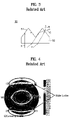
- the light incident to the prism sheet 50 may be divided into those of three regions, namely, a full reflection region, a condensing region, and a side lobe region, as shown in FIG. 3 .
- the light in the full reflection region namely, light A vertically incident to the condensing film 52 , is fully reflected by the first and second inclined faces of the prism crests 54 , so that the light A is directed back to the light guide plate 20 .
- the light A is condensed after being recycled.
- the light in the condensing region namely, light B incident to the condensing film 52 at a certain angle, is refracted by the first and second inclined faces of the prism crests 54 , so that the light B is condensed.
- the present invention is directed to a prism sheet and a backlight unit using the same that substantially obviate one or more problems due to limitations and disadvantages of the related art.
- An advantage of the present invention is to provide a prism sheet capable of achieving an enhancement in light efficiency and viewing angle characteristics, and a backlight unit using the prism sheet.
- a prism sheet includes: a condensing film which transmits light incident to the condensing film; a plurality of prism crests on the condensing film having apexes; and a plurality of reflection patterns formed on the condensing film such that each of the reflection patterns faces a boundary of adjacent prism crests associated with the reflection pattern to reflect light incident onto the reflection patterns.
- a backlight unit in another aspect of the present invention, includes: a lamp that emits light; a light guide plate that receives the light emitted from the light, and changes a path direction of the light to a direction substantially perpendicular to an upper surface of the light guide plate; and a prism sheet that condenses the light emerging from the light guide plate, wherein the prism sheet includes: a condensing film that transmits the light emerging from the light guide plate; a plurality of prism crests on the condensing film having apexes; and a plurality of reflection patterns formed on the condensing film such that each of the reflection patterns faces a boundary of adjacent prism crests associated with the reflection pattern to reflect light incident onto the reflection patterns.
- a backlight unit in another aspect of the present invention, includes: a plurality of lamps that emit light; a bottom cover that receives and supports the lamps; a diffusion plate that covers an upper surface of the bottom cover and diffuses light emitted from the lamps; and a prism sheet that condenses light emerging from the diffusion plate, wherein the prism sheet includes: a condensing film that transmits the light emerging from the light guide plate; a plurality of prism crests on the condensing film having apexes; and a plurality of reflection patterns formed on the condensing film such that each of the reflection patterns faces a boundary of adjacent prism crests associated with the reflection pattern to reflect light incident onto the reflection patterns.
- FIG. 1 is a schematic view illustrating a conventional backlight unit
- FIG. 2 is a perspective view illustrating the prism sheet shown in FIG. 1 ;
- FIG. 3 is a schematic view illustrating optical characteristics of crests of the prism shown in FIG. 2 ;
- FIG. 4 is a diagram illustrating light transmission and angular light distribution in the prism sheet shown in FIG. 2 ;
- FIG. 5 is a perspective view illustrating a prism sheet according to a first embodiment of the present invention.
- FIG. 6 is a cross-sectional view taken along the line I-I′ of FIG. 5 , illustrating the path of the light;
- FIG. 7 is a perspective view illustrating a prism sheet according to a second embodiment of the present invention.
- FIG. 8 is a cross-sectional view taken along the line II-II′ of FIG. 7 , illustrating the path of the light;
- FIG. 9 is a perspective view illustrating a prism sheet according to a third embodiment of the present invention.
- FIG. 10 is a plan view illustrating the prism sheet according to the third embodiment of the present invention.
- FIG. 11 is a cross-sectional view taken along the line III-III′ of FIG. 9 , illustrating the traveling direction of light;
- FIG. 12 is a perspective view illustrating a prism sheet according to a fourth embodiment of the present invention.
- FIG. 13 is a cross-sectional view taken along the line VI-VI′ of FIG. 12 , illustrating the path of the light;
- FIG. 14 is a sectional view illustrating a backlight unit according to a first embodiment of the present invention.
- FIG. 15 is a sectional view schematically illustrating a backlight unit according to a second embodiment of the present invention.
- FIG. 16 is a sectional view illustrating a backlight unit according to a third embodiment of the present invention.
- FIG. 5 is a perspective view illustrating a prism sheet according to a first embodiment of the present invention.
- FIG. 6 is a cross-sectional view taken along the line I-I′ of FIG. 5 , illustrating the path of the light.
- the prism sheet according to the first embodiment of the present invention includes a condensing film 152 to which light is incident from a lower surface of the condensing film 152 , and a plurality of prism crests 154 that are formed on an upper surface of the condensing film 152 to extend in parallel in the form of stripes while having apexes.
- the prism sheet also includes a plurality of reflection patterns 156 formed on the upper surface of the condensing film 152 at regions each corresponding to the boundary of the associated adjacent prism crests 154 (associated prism valley).
- the condensing film 152 is made of a transparent material such as polyester (PET).
- Each prism crest 154 has first and second inclined surfaces each having a predetermined inclination from the apex of the prism crest 154 .
- each of the first and second inclined faces is inclined by about 45° from the upper surface of the condensing film 152 .
- Each reflection pattern 156 is formed in the form of a stripe having a rectangular cross-section between the associated adjacent prism crests 154 to extend in parallel to the boundary of the facing first and second inclined surfaces of the associated adjacent prism crests 154 , namely, the associated prism valley.
- Each reflection pattern 156 is made of a material such as titanium oxide (TiO2) or magnesium oxide (MgO) containing a reflective material to reflect incidence light.
- TiO2 titanium oxide
- MgO magnesium oxide
- the positions of the reflection patterns 156 may be varied in accordance with the refractive index of the condensing film 152 and the angle of the prism crests 154 .
- the central position of each reflection pattern 156 faces the associated prism valley.
- each reflection pattern 156 may be varied in accordance with a desired angle and desired refractive index of the prism crests 154 and desired angular distribution of the emitted light.
- the prism sheet according to the first embodiment of the present invention may be divided into three regions, namely, a full reflection region, a condensing region, and a side lobe region.
- the light in the full reflection region namely, light A vertically incident to the condensing film 152 , is fully reflected by the first and second inclined faces of the prism crests 154 toward the lower surface of the condensing film 152 , so that the light A is condensed while being recycled.
- the light in the condensing region namely, light B incident to the condensing film 152 at a certain angle, is refracted by the first and second inclined faces of the prism crests 154 , so that the light B is externally emitted after being condensed.
- the light in the side lobe region namely, light C incident to the condensing film 152 at a certain angle
- the reflection patterns 156 so that the light C is condensed after being recycled to be the light B of the condensing region.
- the prism sheet according to the first embodiment of the present invention removes the light C traveling toward the side lobe region. Accordingly, it is possible to prevent light from leaking into the sidelobes and thus, to improve the light condensing efficiency and the brightness symmetry. As a result, an enhancement in viewing angle characteristics is achieved.
- the prism sheet according to the first embodiment of the present invention provides reflection regions preventing the presence of side lobe regions while increasing the mechanical durability of the prism sheet by virtue of the reflection patterns 156 formed on the upper surface of the condensing film 152 . Accordingly, an enhancement in light efficiency is achieved.
- FIG. 7 is a perspective view illustrating a prism sheet according to a second embodiment of the present invention.
- FIG. 8 is a cross-sectional view taken along the line II-II′ of FIG. 7 , illustrating the path of the light.
- the prism sheet according to the second embodiment of the present invention includes a condensing film 252 to which light is incident from a lower surface of the condensing film 252 , and a plurality of prism crests 254 that are formed on an upper surface of the condensing film 252 to extend in parallel in the form of stripes while having apexes.
- the prism sheet also includes a plurality of reflection patterns 256 formed on the lower surface of the condensing film 252 at regions each corresponding to the boundary of the associated adjacent prism crests 254 (associated prism valley).
- the prism sheet according to the second embodiment of the present invention has the same configuration as that of the first embodiment shown in FIG. 5 , except that the reflection patterns 256 are formed on the lower surface of the condensing film 252 .
- the prism sheet according to the second embodiment of the present invention removes the light C traveling toward the side lobe region, namely, light leakage because the reflection patterns 256 are formed on the lower surface of the condensing film 252 . Therefore, it is possible to prevent a light leakage phenomenon, and thus, to improve the light condensing efficiency and an enhancement in brightness symmetry. As a result, an improvement in viewing angle characteristics is achieved.
- FIG. 9 is a perspective view illustrating a prism sheet according to a third embodiment of the present invention.
- FIG. 10 is a plan view illustrating the prism sheet according to the third embodiment of the present invention.
- the prism sheet according to the third embodiment of the present invention includes a condensing film 352 to which light is incident from a lower surface of the condensing film 352 , and a plurality of prism crests 354 that are formed on an upper surface of the condensing film 352 in the form of pyramids.
- the prism sheet also includes a plurality of reflection patterns 356 formed on the upper surface of the condensing film 352 at regions each corresponding to the boundary of the associated adjacent prism crests 354 (associated prism valley).
- the condensing film 352 is made of a transparent material such as polyester (PET).
- the prism crests 354 are arranged in a matrix array on the upper surface of the condensing film 352 .
- Each prism crest 354 has a pyramid shape having inclined surfaces each having an inclination of about 45° from the upper surface of the condensing film 352 .
- Each reflection pattern 356 is formed in the form of a stripe having a rectangular cross-section to extend in parallel to the boundary of the associated adjacent prism crests 354 , namely, the associated prism valley.
- each reflection pattern 356 includes a first reflection pattern 356 a which is formed in parallel to a first direction (Y-axis direction) of the condensing film 352 while facing the associated prism valley, and a second reflection pattern 356 b which is formed in parallel to a second direction (X-axis direction) orthogonal to the first direction of the condensing film 352 .
- Each reflection pattern 356 is made of a material such as titanium oxide (TiO2) or magnesium oxide (MgO) containing a reflective material to reflect incident light.
- TiO2 titanium oxide
- MgO magnesium oxide
- the prism sheet according to the third embodiment of the present invention may be divided into three regions, namely, a full reflection region, a condensing region, and a side lobe region.
- the light in the full reflection region namely, light A vertically incident to the condensing film 352 , is fully reflected by the inclined faces of the prism crests 354 toward the lower surface of the condensing film 352 , so that the light A is condensed while being recycled.
- the light in the condensing region namely, light B incident to the condensing film 352 at a certain angle, is refracted by the inclined faces of the prism crests 354 , so that the light B is externally emitted after being condensed.
- the light in the side lobe region namely, light C incident to the condensing film 352 at a certain angle
- the reflection patterns 356 so that the light C is condensed after being recycled to be light B of the condensing region.
- the prism sheet according to the third embodiment of the present invention removes the light C traveling toward the side lobe region because of the reflection patterns 356 . Accordingly, it is possible to prevent a light leakage phenomenon, and thus, to improve the light condensing efficiency and the brightness symmetry. As a result, an improvement in viewing angle characteristics is achieved.
- FIG. 12 is a perspective view illustrating a prism sheet according to a fourth embodiment of the present invention.
- FIG. 13 is a cross-sectional view taken along the line VI-VI′ of FIG. 12 , illustrating the traveling direction of light.
- the prism sheet according to the fourth embodiment of the present invention includes a condensing film 452 to which light is incident from a lower surface of the condensing film 452 , and a plurality of prism crests 454 that are formed on an upper surface of the condensing film 452 in the form of pyramids.
- the prism sheet also includes a plurality of reflection patterns 456 formed on a lower surface of the condensing film 452 at regions each corresponding to the boundary of the associated adjacent prism crests 354 (associated prism valley).
- the prism sheet according to the fourth embodiment of the present invention has the same configuration as that of the third embodiment shown in FIG. 9 , except that the reflection patterns 456 are formed on the lower surface of the condensing film 452 .
- the prism sheet according to the fourth embodiment of the present invention removes the light C traveling toward the side lobe region because the reflection patterns 456 are formed on the lower surface of the condensing film 452 . Therefore, it is possible to prevent a light leakage phenomenon, and thus, to improve the light condensing efficiency and the brightness symmetry. As a result, an improvement in viewing angle characteristics is achieved.
- FIG. 14 is a sectional view illustrating a backlight unit according to a first embodiment of the present invention.
- the backlight unit includes a lamp 110 that emits light, a light guide plate 120 which guides the light incident thereto from the lamp 110 through an incidence face 122 of the light guide plate 120 , and a lamp housing 112 which encloses the incidence face 122 of the light guide plate 120 and the lamp 110 .
- the backlight unit also includes a reflection plate 130 that is arranged beneath the light guide plate 120 , a diffusion sheet 140 that is arranged on the light guide plate 120 to diffuse light emerging from the light guide plate 120 , and a prism sheet 150 that condenses light emerging from the diffusion sheet 140 .
- a cold cathode fluorescent lamp is typically used.
- the lamp 110 is turned on by a lamp drive voltage supplied from an inverter not shown, to irradiate light to the incidence face 122 of the light guide plate 120 provided at one side of the light guide plate 120 .
- the lamp housing 112 is arranged at one side of the light guide plate 120 to enclose the lamp 110 and the incidence face 122 of the light guide plate 120 .
- the lamp housing 112 has a reflective inner surface to reflect the light from the lamp 110 toward the incidence face 122 of the light guide plate 120 .
- the light guide plate 120 enables the incident light from the lamp 110 to reach a position spaced apart from the lamp 110 by a great distance, and guides the incident light toward the diffusion sheet 140 .
- a printed pattern on an inclined lower surface of the light guide plate 120 forms a reflection face, so that light incident to the incidence face 122 is reflected from the inclined lower surface of the light guide plate 120 at a certain angle such that the light travels uniformly toward the diffusion sheet 140 .
- the reflection plate 130 is arranged beneath the light guide plate 120 in order to reflect light incident thereto from the reflection face of the light guide plate 120 toward the light guide plate 120 , and thus, to reduce the loss of light.
- the diffusion sheet 140 diffuses the light emerging from the light guide plate 120 over the entire region of the diffusion sheet 140 , and irradiates the diffused light to the prism sheet 150 .
- the prism sheet 150 includes a condensing film 152 to which light is incident from a lower surface of the condensing film 152 , and a plurality of prism crests 154 that are formed on an upper surface of the condensing film 152 to extend in parallel in the form of stripes while having apexes.
- the prism sheet also includes a plurality of reflection patterns 156 formed on the upper surface of the condensing film 152 at regions each corresponding to the boundary of the associated adjacent prism crests 154 (associated prism valley).
- the above-described structure of the prism sheet 150 is identical to that of the prism sheet according to the first embodiment of the present invention shown in FIG. 5 . Accordingly, details of the prism sheet 150 will be appreciated by referring to the description given with reference to FIG. 5 .
- the above-described backlight unit according to the first embodiment of the present invention can remove light traveling toward the side lobe regions of the prism sheet 150 because of the reflection patterns 156 formed on the condensing film 152 . Accordingly, it is possible to prevent a light leakage phenomenon, and to improve the light condensing efficiency and the brightness symmetry. Accordingly, an improvement in viewing angle characteristics is achieved.
- any one of the prism sheets shown in FIGS. 7 , 9 and 12 may be used.
- FIG. 15 is a sectional view schematically illustrating a backlight unit according to a second embodiment of the present invention.
- the backlight unit includes a light guide plate 220 having a flat plate structure, lamps 210 a and 210 b that face incidence faces 222 a and 222 b formed at opposite sides of the light guide plate 220 , respectively, and lamp housings 212 a and 212 b which enclose the incidence faces 222 a and 222 b of the light guide plate 220 and the lamps 210 a and 210 b , respectively.
- the backlight unit also includes a reflection plate 130 that is arranged beneath the light guide plate 220 , a diffusion sheet 140 that is arranged on the light guide plate 220 to diffuse light emerging from the light guide plate 220 , and a prism sheet 150 that condenses light emerging from the diffusion sheet 140 .
- the above-described backlight unit according to the second embodiment of the present invention has the same configuration as that of the first embodiment shown in FIG. 14 , except for the light guide plate 220 and the lamps 210 a and 210 b arranged to face the opposite sides of the light guide plate 220 .
- the backlight unit according to the second embodiment of the present invention can greatly enhance the brightness of externally-emitted light because light is incident to the light guide plate 220 at opposite sides thereof using the lamps 210 a and 210 b.
- the above-described backlight unit according to the second embodiment of the present invention can remove light traveling toward the side lobe regions of the prism sheet 150 because of the reflection patterns 156 formed on the condensing; film 152 . Accordingly, it is possible to prevent a light leakage phenomenon, and to improve the light condensing efficiency and the brightness symmetry. Accordingly, an improvement in viewing angle characteristics is achieved.
- any one of the prism sheets shown in FIGS. 7 , 9 and 12 may be used.
- FIG. 16 is a sectional view illustrating a backlight unit according to a third embodiment of the present invention.
- the backlight unit includes a plurality of lamps 310 that emit light, a bottom cover 312 that receives the lamps 310 , a diffusion plate 320 that covers an upper surface of the bottom cover 312 and diffuses light incident from the lamps 310 over the entire region of the diffusion plate 320 , and a prism sheet 150 that is arranged over the diffusion plate 320 to condense light emerging from the diffusion plate 320 .
- each lamp 310 a cold cathode fluorescent lamp is typically used.
- the lamps 310 are turned on by a lamp drive voltage supplied from an inverter not shown to irradiate light to a lower surface of the diffusion plate 320 .
- the bottom cover 312 receives and supports the lamps 310 .
- a reflection sheet not shown is attached to an inner surface of the bottom cover 312 , in order to reflect light incident from the lamps 310 toward the diffusion plate 320 .
- the diffusion plate 320 is arranged to cover the upper surface of the bottom cover 312 .
- the diffusion plate 320 diffuses light incident from the lamps 310 and the reflection sheet of the bottom cover 312 over the entire region of the diffusion plate 320 , and irradiates the diffused light to the prism sheet 150 .
- the prism sheet 150 includes a condensing film 152 to which light emerging from the diffusion plate - 320 is incident, and a plurality of prism crests 154 which are formed on an upper surface of the condensing film 152 to extend in parallel in the form of stripes while having apexes, respectively.
- the prism sheet also includes a plurality of reflection patterns 156 formed on the upper surface of the condensing film 152 at regions each corresponding to the boundary of the associated adjacent prism crests 154 (associated prism valley).
- the above-described structure of the prism sheet 150 is identical to that of the prism sheet according to the first embodiment of the present invention shown in FIG. 5 . Accordingly, details of the prism sheet 150 will be appreciated by referring to the description given with reference to FIG. 5 .
- the backlight unit according to the third embodiment of the present invention can greatly enhance the brightness of externally-emitted light because the light from the lamps 310 is directly irradiated to the lower surface of the diffusion plate 320 . Also, the backlight unit according to the third embodiment of the present invention can remove light traveling toward the side lobe regions of the prism sheet 150 because of the reflection patterns 156 formed on the condensing film 152 . Accordingly, it is possible to prevent a light leakage phenomenon, and to improve the light condensing efficiency and the brightness symmetry. Accordingly, an improvement in viewing angle characteristics is achieved.
- any one of the prism sheets shown in FIGS. 7 , 9 and 12 may be used.
- the backlight unit according to any one of the first through third embodiment of the present invention can be used as a light source for an LCD device.
- reflection patterns are formed on an upper or lower surface of a condensing film formed with a plurality of prism crests at regions corresponding to respective prism valleys. According, it is possible to remove light of side lobe regions, and thus, to prevent a light leakage phenomenon. As a result, it is possible to achieve an enhancement in light condensing efficiency and an enhancement in brightness symmetry, and thus, to achieve an enhancement in viewing angle characteristics.
Abstract
Description
-
- Thus, the conventional backlight unit has problems caused by the structure of the
prism sheet 50, namely, viewing angle asymmetry caused by brightness asymmetry and a degradation in light efficiency caused by side lobes.
- Thus, the conventional backlight unit has problems caused by the structure of the
Claims (18)
Applications Claiming Priority (2)
| Application Number | Priority Date | Filing Date | Title |
|---|---|---|---|
| KRP2005-57014 | 2005-06-29 | ||
| KR1020050057014A KR101212136B1 (en) | 2005-06-29 | 2005-06-29 | Prism sheet and back light unit |
Publications (2)
| Publication Number | Publication Date |
|---|---|
| US20070002576A1 US20070002576A1 (en) | 2007-01-04 |
| US7407317B2 true US7407317B2 (en) | 2008-08-05 |
Family
ID=35840768
Family Applications (1)
| Application Number | Title | Priority Date | Filing Date |
|---|---|---|---|
| US11/314,342 Expired - Fee Related US7407317B2 (en) | 2005-06-29 | 2005-12-22 | Prism sheet and backlight unit using the same |
Country Status (6)
| Country | Link |
|---|---|
| US (1) | US7407317B2 (en) |
| JP (1) | JP4357477B2 (en) |
| KR (1) | KR101212136B1 (en) |
| CN (1) | CN100427976C (en) |
| DE (1) | DE102005061307B4 (en) |
| GB (1) | GB2427676B (en) |
Cited By (7)
| Publication number | Priority date | Publication date | Assignee | Title |
|---|---|---|---|---|
| US20070086207A1 (en) * | 2006-01-13 | 2007-04-19 | Optical Research Associates | Display systems including light enhancing structures with arrays of elongate features |
| US20070091616A1 (en) * | 2006-01-13 | 2007-04-26 | Optical Research Associates | Light enhancing structures with multiple arrays of elongate features of varying characteristics |
| US20070091617A1 (en) * | 2006-01-13 | 2007-04-26 | Optical Research Associates | Light enhancing structures with a plurality of arrays of elongate features |
| US20100039586A1 (en) * | 2008-08-12 | 2010-02-18 | Lms Co., Ltd | Optical element and backlight unit and liquid crystal display having the same |
| US20100321609A1 (en) * | 2009-06-19 | 2010-12-23 | Apple Inc. | Edge-lit backlight unit with thin profile |
| US20110058389A1 (en) * | 2009-09-10 | 2011-03-10 | Coretronic Corporation | Brightness enhancement film and backlight module |
| US20180003883A1 (en) * | 2016-07-01 | 2018-01-04 | Boe Technology Group Co., Ltd. | Light-guiding panel, backlight module, and display device |
Families Citing this family (20)
| Publication number | Priority date | Publication date | Assignee | Title |
|---|---|---|---|---|
| JP5091490B2 (en) * | 2007-01-22 | 2012-12-05 | 富士フイルム株式会社 | Optical sheet and manufacturing method thereof |
| JP2008275655A (en) * | 2007-04-25 | 2008-11-13 | Toppan Printing Co Ltd | Optical sheet backlight unit using the same, and display device |
| KR101362729B1 (en) | 2007-05-08 | 2014-02-12 | 삼성디스플레이 주식회사 | Optical sheet, method of manufacturing the same and display apparatus having the same |
| KR101351886B1 (en) * | 2007-05-14 | 2014-01-17 | 엘지디스플레이 주식회사 | One-body multi functional optical sheet for liquid crystal display device |
| JP2009162868A (en) * | 2007-12-28 | 2009-07-23 | Hitachi Ltd | Liquid crystal display device and method of forming reflective member for liquid crystal display device |
| JP5298569B2 (en) * | 2008-02-27 | 2013-09-25 | 凸版印刷株式会社 | Lens sheet, optical sheet for display, backlight unit using the same, and display device |
| JP4913084B2 (en) * | 2008-03-04 | 2012-04-11 | 株式会社クラレ | Optical sheet and method for manufacturing optical sheet |
| JP5272508B2 (en) * | 2008-05-12 | 2013-08-28 | 凸版印刷株式会社 | Optical sheet, backlight unit and display device |
| JP2010205713A (en) * | 2008-06-27 | 2010-09-16 | Seiko Instruments Inc | Lighting device, and display device using the same |
| KR101540216B1 (en) * | 2008-11-03 | 2015-07-29 | 삼성디스플레이 주식회사 | Optical member and display device having the same |
| KR101258902B1 (en) * | 2008-12-31 | 2013-05-07 | 엘지디스플레이 주식회사 | Prism sheet, back light unit and liquid crystal display device having thereof |
| KR101739139B1 (en) * | 2010-12-30 | 2017-05-23 | 엘지디스플레이 주식회사 | Stereoscopic image display |
| KR20140066522A (en) * | 2012-11-23 | 2014-06-02 | 삼성디스플레이 주식회사 | A backlight unit and a display apparatus having the backlight unit |
| CN104965342B (en) * | 2015-07-08 | 2017-09-29 | 京东方科技集团股份有限公司 | A kind of display device |
| US10051060B2 (en) * | 2015-12-04 | 2018-08-14 | International Business Machines Corporation | Sensor data segmentation and virtualization |
| US10072951B2 (en) | 2015-12-04 | 2018-09-11 | International Business Machines Corporation | Sensor data segmentation and virtualization |
| CN107132601A (en) * | 2017-05-23 | 2017-09-05 | 张家港康得新光电材料有限公司 | A kind of brightness enhancement film and backlight assembly |
| TWI646360B (en) * | 2018-02-09 | 2019-01-01 | 友達光電股份有限公司 | 稜鏡-type polarizing structure and backlight module therewith |
| CN116343584A (en) | 2021-12-22 | 2023-06-27 | 瑞轩科技股份有限公司 | Backlight module of display |
| TWI805291B (en) * | 2021-12-22 | 2023-06-11 | 瑞軒科技股份有限公司 | Backlight module of display |
Citations (21)
| Publication number | Priority date | Publication date | Assignee | Title |
|---|---|---|---|---|
| US2248638A (en) | 1937-02-22 | 1941-07-08 | Merton Thomas Ralph | Sheet material with prismatic surfaces |
| US4542449A (en) | 1983-08-29 | 1985-09-17 | Canadian Patents & Development Limited | Lighting panel with opposed 45° corrugations |
| US4906070A (en) | 1985-11-21 | 1990-03-06 | Minnesota Mining And Manufacturing Company | Totally internally reflecting thin, flexible film |
| US5056892A (en) | 1985-11-21 | 1991-10-15 | Minnesota Mining And Manufacturing Company | Totally internally reflecting thin, flexible film |
| US5627926A (en) | 1992-09-16 | 1997-05-06 | Hitachi, Ltd. | Prism plate for efficiently emitting light flux within a predetermined range, and liquid crystal indicator and indicator illumination method using the same |
| US5647655A (en) * | 1992-06-04 | 1997-07-15 | Tosoh Corporation | Back lighting device |
| JPH09281310A (en) | 1996-04-09 | 1997-10-31 | Mitsubishi Rayon Co Ltd | Prism sheet and surface illumination device formed by using the same |
| US5816677A (en) * | 1905-03-01 | 1998-10-06 | Canon Kabushiki Kaisha | Backlight device for display apparatus |
| US5914760A (en) * | 1996-06-21 | 1999-06-22 | Casio Computer Co., Ltd. | Surface light source device and liquid crystal display device using the same |
| US6024462A (en) | 1997-06-10 | 2000-02-15 | The University Of British Columbia | High efficiency high intensity backlighting of graphic displays |
| US6079844A (en) * | 1997-06-10 | 2000-06-27 | The University Of British Columbia | High efficiency high intensity backlighting of graphic displays |
| US20020105793A1 (en) * | 2000-12-12 | 2002-08-08 | Masaharu Oda | Surface lighting device |
| US6454452B1 (en) * | 1999-04-22 | 2002-09-24 | Mitsubishi Denki Kabushiki Kaisha | Backlight for liquid crystal display device |
| EP1486802A1 (en) | 2003-06-09 | 2004-12-15 | Kabushiki Kaisha Toyota Jidoshokki | Textured optical path converting element and display backlight incorporating same |
| JP2004361821A (en) | 2003-06-06 | 2004-12-24 | Seiko Epson Corp | Spatial light modulator and projector |
| US20050007513A1 (en) | 2003-03-05 | 2005-01-13 | Lee Jeong-Hwan | Optical sheet and LCD apparatus using the same |
| US6851815B2 (en) * | 2001-04-09 | 2005-02-08 | Samsung Electronics Co., Ltd. | Light guide plate with trigonal recesses |
| US20050046321A1 (en) * | 2001-10-31 | 2005-03-03 | Yoshinori Suga | Display apparatus |
| US6876408B2 (en) * | 2000-02-14 | 2005-04-05 | Fuji Photo Film Co., Ltd. | Collimating plate, lighting apparatus and liquid crystal display apparatus |
| US20050105282A1 (en) * | 2003-11-14 | 2005-05-19 | Hon Hai Precision Industry Co., Ltd. | Surface light source having light guide plate with prisms |
| US20060050534A1 (en) * | 2004-09-09 | 2006-03-09 | Lee Jeong-Hwan | Prism sheet, backlight assembly and liquid crystal display device having the same |
Family Cites Families (3)
| Publication number | Priority date | Publication date | Assignee | Title |
|---|---|---|---|---|
| JP2000010094A (en) * | 1998-06-19 | 2000-01-14 | Nec Corp | Backlight device |
| JP2004045645A (en) * | 2002-07-10 | 2004-02-12 | Yuka Denshi Co Ltd | Surface light source device and liquid crystal display device |
| JP3873835B2 (en) * | 2002-07-22 | 2007-01-31 | セイコーエプソン株式会社 | Liquid crystal display device and electronic device |
-
2005
- 2005-06-29 KR KR1020050057014A patent/KR101212136B1/en active IP Right Grant
- 2005-12-20 GB GB0525889A patent/GB2427676B/en not_active Expired - Fee Related
- 2005-12-21 DE DE102005061307A patent/DE102005061307B4/en not_active Expired - Fee Related
- 2005-12-22 US US11/314,342 patent/US7407317B2/en not_active Expired - Fee Related
- 2005-12-26 CN CNB200510023095XA patent/CN100427976C/en not_active Expired - Fee Related
- 2005-12-26 JP JP2005373204A patent/JP4357477B2/en not_active Expired - Fee Related
Patent Citations (21)
| Publication number | Priority date | Publication date | Assignee | Title |
|---|---|---|---|---|
| US5816677A (en) * | 1905-03-01 | 1998-10-06 | Canon Kabushiki Kaisha | Backlight device for display apparatus |
| US2248638A (en) | 1937-02-22 | 1941-07-08 | Merton Thomas Ralph | Sheet material with prismatic surfaces |
| US4542449A (en) | 1983-08-29 | 1985-09-17 | Canadian Patents & Development Limited | Lighting panel with opposed 45° corrugations |
| US4906070A (en) | 1985-11-21 | 1990-03-06 | Minnesota Mining And Manufacturing Company | Totally internally reflecting thin, flexible film |
| US5056892A (en) | 1985-11-21 | 1991-10-15 | Minnesota Mining And Manufacturing Company | Totally internally reflecting thin, flexible film |
| US5647655A (en) * | 1992-06-04 | 1997-07-15 | Tosoh Corporation | Back lighting device |
| US5627926A (en) | 1992-09-16 | 1997-05-06 | Hitachi, Ltd. | Prism plate for efficiently emitting light flux within a predetermined range, and liquid crystal indicator and indicator illumination method using the same |
| JPH09281310A (en) | 1996-04-09 | 1997-10-31 | Mitsubishi Rayon Co Ltd | Prism sheet and surface illumination device formed by using the same |
| US5914760A (en) * | 1996-06-21 | 1999-06-22 | Casio Computer Co., Ltd. | Surface light source device and liquid crystal display device using the same |
| US6079844A (en) * | 1997-06-10 | 2000-06-27 | The University Of British Columbia | High efficiency high intensity backlighting of graphic displays |
| US6024462A (en) | 1997-06-10 | 2000-02-15 | The University Of British Columbia | High efficiency high intensity backlighting of graphic displays |
| US6454452B1 (en) * | 1999-04-22 | 2002-09-24 | Mitsubishi Denki Kabushiki Kaisha | Backlight for liquid crystal display device |
| US6876408B2 (en) * | 2000-02-14 | 2005-04-05 | Fuji Photo Film Co., Ltd. | Collimating plate, lighting apparatus and liquid crystal display apparatus |
| US20020105793A1 (en) * | 2000-12-12 | 2002-08-08 | Masaharu Oda | Surface lighting device |
| US6851815B2 (en) * | 2001-04-09 | 2005-02-08 | Samsung Electronics Co., Ltd. | Light guide plate with trigonal recesses |
| US20050046321A1 (en) * | 2001-10-31 | 2005-03-03 | Yoshinori Suga | Display apparatus |
| US20050007513A1 (en) | 2003-03-05 | 2005-01-13 | Lee Jeong-Hwan | Optical sheet and LCD apparatus using the same |
| JP2004361821A (en) | 2003-06-06 | 2004-12-24 | Seiko Epson Corp | Spatial light modulator and projector |
| EP1486802A1 (en) | 2003-06-09 | 2004-12-15 | Kabushiki Kaisha Toyota Jidoshokki | Textured optical path converting element and display backlight incorporating same |
| US20050105282A1 (en) * | 2003-11-14 | 2005-05-19 | Hon Hai Precision Industry Co., Ltd. | Surface light source having light guide plate with prisms |
| US20060050534A1 (en) * | 2004-09-09 | 2006-03-09 | Lee Jeong-Hwan | Prism sheet, backlight assembly and liquid crystal display device having the same |
Cited By (13)
| Publication number | Priority date | Publication date | Assignee | Title |
|---|---|---|---|---|
| US7866871B2 (en) | 2006-01-13 | 2011-01-11 | Avery Dennison Corporation | Light enhancing structures with a plurality of arrays of elongate features |
| US20070091616A1 (en) * | 2006-01-13 | 2007-04-26 | Optical Research Associates | Light enhancing structures with multiple arrays of elongate features of varying characteristics |
| US20070091617A1 (en) * | 2006-01-13 | 2007-04-26 | Optical Research Associates | Light enhancing structures with a plurality of arrays of elongate features |
| US20070086207A1 (en) * | 2006-01-13 | 2007-04-19 | Optical Research Associates | Display systems including light enhancing structures with arrays of elongate features |
| US7674028B2 (en) | 2006-01-13 | 2010-03-09 | Avery Dennison Corporation | Light enhancing structures with multiple arrays of elongate features of varying characteristics |
| US9075177B2 (en) | 2006-01-13 | 2015-07-07 | Avery Dennison Corporation | Light enhancing structures with a plurality of arrays of elongate features |
| US20100039586A1 (en) * | 2008-08-12 | 2010-02-18 | Lms Co., Ltd | Optical element and backlight unit and liquid crystal display having the same |
| US8508690B2 (en) | 2008-08-12 | 2013-08-13 | Lms Co., Ltd | Optical element and backlight unit and liquid crystal display having the same |
| US8248554B2 (en) | 2009-06-19 | 2012-08-21 | Apple Inc. | Edge-lit backlight unit with thin profile |
| US20100321609A1 (en) * | 2009-06-19 | 2010-12-23 | Apple Inc. | Edge-lit backlight unit with thin profile |
| US20110058389A1 (en) * | 2009-09-10 | 2011-03-10 | Coretronic Corporation | Brightness enhancement film and backlight module |
| US20180003883A1 (en) * | 2016-07-01 | 2018-01-04 | Boe Technology Group Co., Ltd. | Light-guiding panel, backlight module, and display device |
| US10330853B2 (en) * | 2016-07-01 | 2019-06-25 | Boe Technology Group Co., Ltd. | Light-guiding panel, backlight module, and display device |
Also Published As
| Publication number | Publication date |
|---|---|
| GB2427676B (en) | 2007-09-05 |
| KR20070001494A (en) | 2007-01-04 |
| GB2427676A (en) | 2007-01-03 |
| DE102005061307B4 (en) | 2008-05-15 |
| GB0525889D0 (en) | 2006-02-01 |
| KR101212136B1 (en) | 2012-12-14 |
| US20070002576A1 (en) | 2007-01-04 |
| JP2007011264A (en) | 2007-01-18 |
| JP4357477B2 (en) | 2009-11-04 |
| CN1888939A (en) | 2007-01-03 |
| CN100427976C (en) | 2008-10-22 |
| DE102005061307A1 (en) | 2007-01-04 |
Similar Documents
| Publication | Publication Date | Title |
|---|---|---|
| US7407317B2 (en) | Prism sheet and backlight unit using the same | |
| US7665877B2 (en) | Prism sheet, backlight unit using the same, and method for fabricating the prism sheet | |
| US8045092B2 (en) | Multifunctional optical sheet and liquid crystal display device including the same | |
| JP3860558B2 (en) | Display panel, liquid crystal display panel, and liquid crystal display device | |
| KR100725011B1 (en) | Prism sheet and back light assembly | |
| KR100898100B1 (en) | Prism sheet | |
| US7905647B2 (en) | Prism sheet, back light unit using the same and liquid crystal display device having the back light unit | |
| US7275853B2 (en) | Illuminating device, light guide body and liquid crystal display device | |
| US6827460B2 (en) | Lighting panel having light-collecting function and display device using same | |
| KR101161435B1 (en) | Illumination apparatus | |
| US7628526B2 (en) | Back light unit | |
| US20050073828A1 (en) | Backlight unit for liquid crystal display | |
| US20070002585A1 (en) | Backlight unit | |
| JP4138787B2 (en) | Light guide plate, flat illumination device, and liquid crystal display device | |
| KR20090027395A (en) | Prism sheet having prisms of zig-zag arrangement patterns, back light unit having the prism sheet and liquid crystal display device having the back light unit | |
| US8147112B2 (en) | Backlight assembly and liquid crystal display having the same | |
| KR20070071686A (en) | Prism sheet and back light unit | |
| KR101212143B1 (en) | A prism sheet and a back light unit using the same | |
| KR101234841B1 (en) | Prism sheet having lengthwise wave patterned optical condensing portions and reflection portions, back light unit having the prism sheet and liquid crystal display device having the back light unit | |
| KR20000024140A (en) | a back light unit | |
| KR101501523B1 (en) | Optical sheet and display device having the same | |
| JP4394564B2 (en) | Direct type backlight | |
| KR20090055148A (en) | Backlight unit and liquid cristal display device usimg the same | |
| KR20210121699A (en) | Optical film to reduce hotspots | |
| KR20070001472A (en) | Optical plate and back light unit using the same |
Legal Events
| Date | Code | Title | Description |
|---|---|---|---|
| AS | Assignment |
Owner name: LG.PHILIPS LCD CO., LTD., KOREA, REPUBLIC OF Free format text: ASSIGNMENT OF ASSIGNORS INTEREST;ASSIGNORS:LEE, MAN HOAN;KANG, JAE KYUNG;YOON, JI SU;AND OTHERS;REEL/FRAME:017375/0666 Effective date: 20051221 |
|
| FEPP | Fee payment procedure |
Free format text: PAYOR NUMBER ASSIGNED (ORIGINAL EVENT CODE: ASPN); ENTITY STATUS OF PATENT OWNER: LARGE ENTITY |
|
| STCF | Information on status: patent grant |
Free format text: PATENTED CASE |
|
| AS | Assignment |
Owner name: LG DISPLAY CO., LTD., KOREA, REPUBLIC OF Free format text: CHANGE OF NAME;ASSIGNOR:LG.PHILIPS LCD CO., LTD.;REEL/FRAME:021754/0230 Effective date: 20080304 Owner name: LG DISPLAY CO., LTD.,KOREA, REPUBLIC OF Free format text: CHANGE OF NAME;ASSIGNOR:LG.PHILIPS LCD CO., LTD.;REEL/FRAME:021754/0230 Effective date: 20080304 |
|
| FEPP | Fee payment procedure |
Free format text: PAYER NUMBER DE-ASSIGNED (ORIGINAL EVENT CODE: RMPN); ENTITY STATUS OF PATENT OWNER: LARGE ENTITY |
|
| FPAY | Fee payment |
Year of fee payment: 4 |
|
| FPAY | Fee payment |
Year of fee payment: 8 |
|
| FEPP | Fee payment procedure |
Free format text: MAINTENANCE FEE REMINDER MAILED (ORIGINAL EVENT CODE: REM.); ENTITY STATUS OF PATENT OWNER: LARGE ENTITY |
|
| LAPS | Lapse for failure to pay maintenance fees |
Free format text: PATENT EXPIRED FOR FAILURE TO PAY MAINTENANCE FEES (ORIGINAL EVENT CODE: EXP.); ENTITY STATUS OF PATENT OWNER: LARGE ENTITY |
|
| STCH | Information on status: patent discontinuation |
Free format text: PATENT EXPIRED DUE TO NONPAYMENT OF MAINTENANCE FEES UNDER 37 CFR 1.362 |
|
| FP | Lapsed due to failure to pay maintenance fee |
Effective date: 20200805 |