US7411787B2 - Storage control device - Google Patents

Storage control device Download PDF

Info

Publication number
US7411787B2
US7411787B2 US11/347,311 US34731106A US7411787B2 US 7411787 B2 US7411787 B2 US 7411787B2 US 34731106 A US34731106 A US 34731106A US 7411787 B2 US7411787 B2 US 7411787B2
Authority
US
United States
Prior art keywords
cooling
control device
storage control
subjects
section
Prior art date
Legal status (The legal status is an assumption and is not a legal conclusion. Google has not performed a legal analysis and makes no representation as to the accuracy of the status listed.)
Expired - Fee Related, expires
Application number
US11/347,311
Other versions
US20070127207A1 (en
Inventor
Yasuyuki Katakura
Kenichi Miyamoto
Current Assignee (The listed assignees may be inaccurate. Google has not performed a legal analysis and makes no representation or warranty as to the accuracy of the list.)
Hitachi Ltd
Original Assignee
Hitachi Ltd
Priority date (The priority date is an assumption and is not a legal conclusion. Google has not performed a legal analysis and makes no representation as to the accuracy of the date listed.)
Filing date
Publication date
Application filed by Hitachi Ltd filed Critical Hitachi Ltd
Assigned to HITACHI, LTD. reassignment HITACHI, LTD. ASSIGNMENT OF ASSIGNORS INTEREST (SEE DOCUMENT FOR DETAILS). Assignors: KATAKURA, YASUYUKI, MIYAMOTO, KENICHI
Publication of US20070127207A1 publication Critical patent/US20070127207A1/en
Application granted granted Critical
Publication of US7411787B2 publication Critical patent/US7411787B2/en
Expired - Fee Related legal-status Critical Current
Adjusted expiration legal-status Critical

Links

Images

Classifications

    • GPHYSICS
    • G11INFORMATION STORAGE
    • G11BINFORMATION STORAGE BASED ON RELATIVE MOVEMENT BETWEEN RECORD CARRIER AND TRANSDUCER
    • G11B33/00Constructional parts, details or accessories not provided for in the other groups of this subclass
    • G11B33/14Reducing influence of physical parameters, e.g. temperature change, moisture, dust
    • GPHYSICS
    • G11INFORMATION STORAGE
    • G11BINFORMATION STORAGE BASED ON RELATIVE MOVEMENT BETWEEN RECORD CARRIER AND TRANSDUCER
    • G11B33/00Constructional parts, details or accessories not provided for in the other groups of this subclass
    • G11B33/12Disposition of constructional parts in the apparatus, e.g. of power supply, of modules

Definitions

  • the present invention relates to a technique for cooling various subjects for cooling within a storage control device.
  • storage control devices equipped with cooling mechanisms there are, for example, the storage control devices disclosed in Japanese Patent Laid-Open Publication 2002-232177, Japanese Patent Laid-Open Publication 2001-307474, and Japanese Patent Laid-Open Publication Heisei 8-273345.
  • a method is considered of cooling subjects for cooling of a plurality of types within the storage control device with a single cooling mechanism (in concrete terms, for example, cooling them with air which is blown by a single fan).
  • an object of the present invention is to enhance the cooling efficiency of a storage control device.
  • the storage control device includes two or more groups of subjects for cooling, including m subjects for cooling of the same type among M subjects for cooling (where m is a integer greater than or equal to 2, and M>m), and two or more cooling mechanisms which respectively correspond to the two or more groups of subjects for cooling.
  • Each of the cooling mechanisms is a mechanism for cooling the subjects for cooling included in its corresponding group of subjects for cooling, and is independent from other cooling mechanisms.
  • each of the cooling mechanisms includes a cooling unit (for example a fan) and a cooling flow conduit (for example, a flow conduit for air which is driven by the fan), then each of the cooling mechanisms can be made to be independent from other cooling mechanisms by making each of the cooling units and each of the cooling flow conduits separate from the other cooling units and the other cooling flow conduits.
  • making each of the cooling flow conduits separate from the other cooling flow conduits of course includes the possibility that the cooling flow conduits should intersect one another, but also includes the possibility that they may intersect. In other words, making each cooling flow conduit separate from the other cooling flow conduits may mean that the cooling flow conduits are made so as not to be common more than a predetermined distance.
  • air is sucked into the storage control device by each of the cooling mechanisms, and the sucked in air cools the subjects for cooling included in the group of subjects for cooling corresponding to each of the cooling mechanisms, and is then expelled to the exterior of the storage control device; and the air flow conduit for each cooling mechanism is independent from the flow conduits for the air sucked in by the other cooling mechanisms.
  • a first, a second, and a third group of subjects for cooling in the two or more groups of subjects for cooling, there are included a first, a second, and a third group of subjects for cooling.
  • First subjects for cooling which are cooled by a first cooling mechanism corresponding to the first group of subjects for cooling are NAS head substrates or the storage devices.
  • Second subjects for cooling which are cooled by a second cooling mechanism corresponding to the second group of subjects for cooling are logical substrates which are separate from the NAS heads.
  • Third subjects for cooling which are cooled by a third cooling mechanism corresponding to the third group of subjects for cooling are power supplies.
  • the storage control device is divided, from above to below, into a plurality of sections.
  • this plurality of sections there are included: a first section in which a plurality of the NAS head substrates or the storage devices are mounted; a second section in which a plurality of the logical substrates are mounted; and a third section in which the power supplies are mounted.
  • a first section in which a plurality of the NAS head substrates or the storage devices are mounted
  • a second section in which a plurality of the logical substrates are mounted
  • a third section in which the power supplies are mounted.
  • the NAS head substrates are mounted horizontally in the first section.
  • the first cooling mechanism sucks in air from the exterior of the storage control device via the front surface of the storage control device, and expels the sucked in air to the exterior of the storage control device from the rear surface of the storage control device.
  • a plurality of plate shaped NAS units can be mounted in the first section.
  • Each of the NAS units is mounted horizontally, and is provided with one or more NAS heads and a first fan for cooling the one or more NAS heads.
  • the first fan is provided more toward the front side, or the rear side, of the storage control device, than the one or more NAS heads.
  • an input device for a user to input information to the storage control device, or a maintenance terminal incorporating one is mounted so as to be shiftable both in the rearward direction and the forward direction of the storage control device.
  • the input device or maintenance terminal is positioned at a height at which the user can easily input the information.
  • the second section is positioned below the first section.
  • a plurality of the logical substrates are arranged along the width direction of the storage control device, with each of the logical substrates being mounted vertically.
  • the second cooling mechanism sucks in air from the exterior of the storage control device via at least one of the front surface and the rear surface of the storage control device, and blows the sucked in air from the lower side of the plurality of logical substrates to their tops.
  • a flow conduit is provided along which the air which has flowed to the tops of the plurality of logical substrates flows.
  • a second fan which sucks in air from the lower side, where the plurality of logical substrates are present, and expels the air upwards. And the air which has been expelled by the second fan passes along the flow conduit which is provided on at least one of the right side and the left side of the plurality of NAS head substrates.
  • a guide member is provided for guiding the air which has been expelled by the second fan to an inlet of the flow conduit.
  • the third cooling mechanism can suck in air from the exterior of the storage control device via the front surface of the storage control device, and can expel the sucked in air to the exterior of the storage control device from the rear surface of the storage control device.
  • a subject for cooling separate from the power supplies is mounted on the front side of the storage control device, with the power supplies being mounted more to the rear side than the separate subject for cooling.
  • the third cooling mechanism may cool the power supplies with air which has been sucked in from a different location than the location at which the separate subject for cooling is located.
  • the second section is above the third section.
  • the first section is above the second section.
  • a first circuit board is provided in the first section, parallel or substantially parallel to the front surface of the storage control device.
  • the NAS head substrates are oriented horizontally and connected to the first circuit board.
  • the plurality of NAS head substrates are arranged along the height direction of the storage control device.
  • a second circuit board is provided in the second section, parallel or substantially parallel to the front surface of the storage control device.
  • the logical substrates are oriented vertically and connected to both surfaces of the second circuit board.
  • the plurality of logical substrates are arranged along the width direction of the storage control device.
  • a third circuit board is provided in the third section, parallel or substantially parallel to the front surface of the storage control device. And the power supplies are connected to the third circuit board.
  • the wiring on the second circuit board is made to be finer than the wiring on the first circuit board and on the third circuit board.
  • the two or more groups of subjects for cooling and the two or more cooling mechanisms are provided within a chassis of a predetermined size.
  • the second section is above the third section.
  • the first section is above the second section.
  • the NAS head substrates are mounted horizontally in the first section.
  • the first cooling mechanism sucks in air from the exterior of the storage control device via the front surface of the storage control device, and expels the sucked in air to the exterior of the storage control device from the rear surface of the storage control device.
  • the plurality of logical substrates are arranged in the second section along the width direction of the storage control device, and each of the logical substrates is mounted vertically.
  • the second cooling mechanism sucks in air from the exterior of the storage control device via at least one of the front surface and the rear surface of the storage control device, and blows the sucked in air from the lower side of the plurality of logical substrates to their tops.
  • a flow conduit is provided along which the air which has flowed to the tops of the plurality of logical substrates flows.
  • the third cooling mechanism sucks in air from the exterior of the storage control device via the front surface of the storage control device, and expels the sucked in air to the exterior of the storage control device from the rear surface of the storage control device.
  • a temperature sensor is provided to or in the vicinity of at least one of the first section, the second section, and the third section, and, based on the temperature which has been detected by the temperature sensor, the NAS head substrates or the logical substrates are able to control a cooling mechanism corresponding to the detected temperature.
  • At least one of the first section, the second section, and the third section comprises a tubular box; a surface, which is a surface of the tubular box, and which is parallel to at least one of the front surface and the rear surface of the storage control device, is open; and a subject for cooling is mounted via the open surface.
  • the cooling mechanisms are provided so that air which has been expelled to the exterior of the storage control device by each of the cooling mechanisms, and whose temperature is higher than that of the sucked in air, is not sucked in by the other cooling mechanisms.
  • FIG. 1 is an elevation view of an example of a storage device system incorporating a storage control device according to the first embodiment of the present invention
  • FIG. 2 is a perspective view of the storage control device 1 as seen from its front;
  • FIG. 3 is a perspective view of the storage control device 1 as seen from its rear;
  • FIG. 4 is an elevation view of the storage control device 1 ;
  • FIG. 5 is a sectional view of the storage control device taken in a plane shown by arrows 5 - 5 in FIG. 4 ;
  • FIG. 6A is a figure showing a structural example of a NAS unit 5 ;
  • FIG. 6B is a figure showing this NAS unit 5 as seen from above;
  • FIG. 7A is a figure showing the air flow in a third section 9 , and a structural example of a power supply sub-box 25 , in more detail;
  • FIG. 7B is a figure showing an example of an elevation view of the power supply sub-box 25 ;
  • FIG. 8 is a block diagram showing an example of the structure of the storage device system 4 ;
  • FIG. 9 is an explanatory figure showing an example of a cooling control method for a second embodiment of the present invention.
  • FIG. 1 is an elevation view of an example of a storage device system incorporating a storage control device according to the first embodiment of the present invention.
  • the storage device system 4 comprises a storage control device 1 which controls a storage device 150 .
  • This storage control device 1 may be constructed using a chassis 11 .
  • the storage device 150 may be mounted on another chassis 3 .
  • the chassis 11 will be termed the “main chassis 11 ”
  • the chassis 3 will be termed the “extension chassis 3 ”.
  • a plurality of storage devices 150 may be mounted in the extension chassis 3 , so as to be arrayed along both the width direction and the vertical direction of the extension chassis 3 .
  • These storage devices 150 may be of any types, and, in this first embodiment, hard disk drives may be employed.
  • the storage devices 150 are shaped as rectangular parallelepipeds, and may be mounted vertically (in other words, upright (or the storage devices 150 may be mounted horizontally, in other words on their sides).
  • This type of extension chassis 3 is not limited to being one in number; two or more may also be fitted. By doing this, it is possible to increase the storage capacity of the storage device system 4 .
  • the upper surfaces, the lower surfaces, and the side surfaces of the extension chassis 3 and the main chassis 11 may be closed, while their front and rear surfaces may be opened, so as to constitute a casing.
  • cover plates may be provided on the front surface and/or the rear surface of at least one of the extension chassis 3 and the main chassis 11 , so as substantially entirely to cover this surface.
  • Air passage portions may be provided in these cover plates for sucking in air from the exterior of the storage device system 4 to its interior, or for expelling air from the interior of the storage device system 4 to the exterior. These air passage portions may, for example, consist of a large number of holes.
  • FIG. 2 is a perspective view of the storage control device 1 as seen from its front.
  • FIG. 3 is a perspective view of the storage control device 1 as seen from its rear.
  • FIG. 4 is an elevation view of the storage control device 1 .
  • FIG. 5 is a sectional view of the storage control device 1 taken in a plane shown by the arrows 5 - 5 in FIG. 4 .
  • the main chassis 11 is substantially a rectangular parallepiped, and may be divided, from above to below, into a first section 7 , a second section 8 , and a third section 9 .
  • a boundary member (for example a plate) is provided between each section and the neighboring section, for partitioning them from one another.
  • the first section 7 may be considered as a section in which plate shaped NAS units 15 are mounted (these NAS units 15 will be explained hereinafter).
  • a NAS box 10 and a NAS back plane 13 may be provided in this first section 7 .
  • This NAS box 10 is substantially a rectangular parallelepiped, and at least its surface which faces the front surface of the storage control device 1 is opened.
  • the NAS units 15 are inserted into this NAS box 10 from this surface thereof, and they may be connected to the NAS back plane 13 by being inserted further thereinto in the depthwise direction.
  • This NAS back plane 13 may be, for example, a circuit board on which printed wiring has been formed.
  • a maintenance terminal 17 (sometimes, by abbreviating “Service Processor”, this is termed a SVP) which can be shifted forward and backward in the depthwise direction of the storage control device 1 .
  • This maintenance terminal 17 (hereinafter termed a SVP) is, for example, a notebook type personal computer.
  • the SVP 17 may comprise, for example, a control unit (for example, a motherboard on which are mounted a CPU and the like) and an input device (for example, a keyboard).
  • This control unit of the SVP 17 may be provided in the interior of the storage control device 1 , and, in the position of the SVP 17 , instead of the SVP 17 , there may be provided an input device for actuating this control unit.
  • the height from the floor surface at which the storage control device 1 is set up may be set to a height at which the user can easily input information using the input device.
  • this height may be set in the range from 1 m 20 cm to 1 m 30 cm.
  • the SVP 17 may be mounted lower than the plurality of NAS units 15 .
  • spaces 31 for allowing the flow of air are provided in the first section 7 , between the plurality of NAS units 15 and the side surfaces of the storage control device 1 .
  • an air flow conduit space 31 is provided at one side at least of both of the sides of the plurality of NAS units 15 (for example at the NAS box 10 ).
  • these air flow conduit spaces 31 may, for example, simply be gaps between the plurality of NAS units 5 and the sides of the storage control device 1 , by, as in this embodiment, plates (for example, the sides of the NAS box 10 ) being provided so as to constitute partitions between the plurality of NAS units 5 and the air flow conduit spaces 31 , it is possible to prevent the air which is flowing in these air flow conduit spaces 31 from exerting influence on the cooling of the NAS units 5 (the sides of the NAS box 10 may also, for example, be made from an insulating material).
  • These air flow conduit spaces 31 connect from the lower surface of the first section 7 to the upper surface of the storage control device 1 .
  • the air which has entered from the lower surface of the first section 7 into these air flow conduit spaces 31 rises within these spaces 31 and is expelled from the upper surface of the storage control device 1 .
  • the air exhaust outlets from the air flow conduit spaces 31 are not limited to being on the upper surface of the storage control device 1 ; for example, it would also be possible to provide them on the rear surface of the storage control device 1 .
  • the air which has entered into the air flow conduit spaces 31 and has risen therein curves toward the rear enroute, and is expelled from the rear surface of the storage control device 1 .
  • These air flow conduit spaces 31 may be, for example, provided-using so called dead space of the first section 7 .
  • a logic box 20 In the second section 8 , there are comprised a logic box 20 , a fan mounting stand 35 , and one or a plurality of logic fans 19 , 19 , . . . .
  • the logic box 20 is substantially a rectangular parallelepiped, and its surfaces which face the front surface and the rear surface of the storage control device 1 are open.
  • a logic back plane 41 is provided in approximately the middle of the logic box 20 , so as to partition the space within the logic box 20 into a front side and a rear side.
  • This logic back plane 41 may be, for example, a circuit board on which printed wiring is formed.
  • logical substrates 21 are inserted within the logic box 20 and are set vertically (i.e. upright) therein, and these logical substrates 21 are connected to both the sides of the logic back plane 41 .
  • the logical substrates 21 may be connected so as to be lined up in the width direction of the storage control device 1 .
  • this plurality of logical substrates 21 there may be included, for example, at least one of a disk adapter described hereinafter, a channel adapter, a cache memory, and a common memory.
  • the fan mounting stand 35 is provided above the logic box 20 , and the logic fans 19 , 19 , . . . are set up on this fan mounting stand 35 .
  • One or a plurality of openings may be provided in the upper surface of the logic box 20 , or in the fan mounting stand 35 , so as to allow air which is sucked in by the logic fans 19 , 19 , . . . to flow freely.
  • a certain space is provided in the second section 8 above the logic fans 19 , 19 , . . . , and this space joins to the above described air flow conduit spaces 31 , via the boundary between the first section 7 and the second section 8 .
  • openings 38 for example holes or slits
  • the air which has been expelled from the logic fans 19 can flow into the air flow conduit spaces 31 via these openings 38 .
  • a power supply box 30 is provided in the third section 9 .
  • This power supply box 30 is substantially a rectangular parallelepiped, and its sides which face the front surface and the rear surface of the storage control device 1 are open.
  • a power supply back plane 67 is provided in approximately the center of this power supply box 30 , so as to partition the space within the power supply box 30 into a front side and a rear side.
  • This power supply back plane 67 may be, for example, a circuit board on which printed wiring has been formed.
  • Plate shaped batteries 23 are inserted into the power supply box 30 from the front surface of the power supply box 30 , and are set up vertically (i.e. upright) therein, and these batteries 23 are connected to one surface of the power supply back plane 67 .
  • block shaped power supply sub-boxes 25 are inserted into the power supply box 30 from the rear surface of the power supply block 30 , and these power supply sub-boxes 25 are connected to the other surface of the power supply back plane 67 .
  • the subjects for cooling of the same type among the plurality of types of subject for cooling are grouped together, and various sections which correspond to these various groups of types of subjects for cooling are provided to the storage control device 1 , with the various groups of types of subjects for cooling being mounted to the sections which correspond to them.
  • the NAS units 15 comprising NAS head substrates described hereinafter, which are one type of subject for cooling, are mounted in the first section; the logical substrates 21 , which are another type of subject for cooling, are mounted in the second section; and the power supply sub-boxes 25 which comprise power supplies, which are yet another type of subject for cooling, are mounted in the third section.
  • the flows of air which cool the subjects for cooling are made to be independent for each of the sections (or, to put it in another manner, for each of the groups of a type of subject for cooling).
  • the storage control device 1 is so structured, that the air which cools each of the types of subject for cooling does not exert any substantial influence on the cooling of the subjects for cooling of the other types.
  • FIGS. 2 through 5 an outline of the flow of air is shown by the thick arrow signs in FIGS. 2 through 5 , in order to make it easier to explain the essentials of the air flow.
  • the flow of air is not necessarily limited to being as shown by the arrow signs. For example, stagnant pools in the flow of air are caused due to the various members in the storage control device 1 and their temperatures and so on, and the effect thereof is that the air does not flow in straight lines.
  • the arrow signs for the second section 8 indicate that the air which has been sucked in from under the second section 8 turns through a right angle and flows upwards, this is simply for showing that the air which has been sucked in from the lower side of the second section 8 rises and is expelled from the logic fans 19 .
  • Air is sucked into the first section 7 via its front surface from the exterior of the storage control device 1 of, and this sucked in air passes through the NAS units 15 and is expelled from the rear surface of the storage control device 1 to its exterior.
  • a NAS head substrate 110 E within a NAS unit 15 there are comprised a NAS head substrate 110 E, a fan unit 51 which comprises one or more fans (hereinafter termed NAS fans) 53 for cooling the NAS head substrate 110 E, and a power supply 55 and a battery 57 for the NAS head substrate 110 E and/or the NAS fans 53 .
  • the front surface and the rear surface of the NAS unit 15 are made so that air can pass through them (for example, air intake apertures 1001 and air exhaust apertures 1003 may be provided in the front surface and the rear surface). Air is sucked in by the NAS fans 53 from the exterior of the storage control device 15 via its front surface, and this sucked in air is sucked into the NAS unit 15 via the front surface of the NAS unit 15 , and this sucked in air flows over the surface of the NAS head substrate 110 E and is expelled from the rear surface of the NAS unit 15 , with this expelled air being then expelled to the exterior of the storage control device 1 from its rear surface.
  • air intake apertures 1001 and air exhaust apertures 1003 may be provided in the front surface and the rear surface.
  • the air which has been sucked into the storage control device 1 flows over the NAS head substrate 110 E (in particular, for example, over a heat generating portion mounted to this substrate 110 E, for example a CPU or a heat sink), accordingly it is able to cool the NAS head substrate 110 E (in particular, for example, its heat generation portion).
  • the NAS fans 53 may be fitted more to the front side than the NAS head substrate 110 E, as shown in the figure; or, although this is not shown in the figure, they may be fitted more to the rear side than the NAS head substrate 110 E.
  • the second section 8 air is sucked in from the exterior of the storage control device 1 through its front surface, and, among this sucked in air, the air in the vicinity of the lower portion of the second section 8 rises while progressing through the middle of the storage control device 1 , and this air which has risen up is expelled from the second section 8 to the exterior of the storage control device 1 .
  • the air is sucked in by the logic fans 19 from the exterior of the storage control device 15 via its front surface, and, among this sucked in air, the air in the vicinity of the lower portion of the second section 8 rises while progressing through the middle of the storage control device 1 , and this air which has risen up is sucked by the logic fans 19 and is expelled upwards therefrom, and this expelled air flows via the holes 38 provided in the division between the first section 7 and the second section 8 into the air flow conduit spaces 31 , and is then expelled to the exterior of the storage control device 1 .
  • the air which has been sucked into the storage control device 1 flows over the logical substrates 21 (in particular, for example, over heat generating portions mounted to these logical substrates 21 , for example CPUs or heat sinks), accordingly it is able to cool the logical substrates 2 l (in particular, for example, their heat generation portions).
  • the third section 9 air is sucked in from the exterior of the storage control device 1 through its front surface, and this sucked in air passes through the power supply sub-boxes 25 and is expelled from the rear surface of the storage control device 1 to its exterior.
  • a power supply 26 within each of the power supply sub-boxes 25 there are provided a power supply 26 and one or more fans (hereinafter termed power supply fans 63 ) for cooling this power supply 26 .
  • These power supply fans 63 may be provided more toward the rear side (or toward the front side) than the power supply 26 .
  • the air which has been sucked in from the front surface of the storage control device 1 proceeds as far as the vicinity of the center of the storage control device 1 by passing underneath the batteries 23 , and this air is then directed upwards by the guides 65 which are provided in this central vicinity, so that this air which has risen upwards may be sucked in from the front surfaces of the power supply sub-boxes 25 . Since, due to this, it is possible to cool the power supplies 26 with air at a lower temperature than air which has passed past the batteries 23 and has been heated up thereby, accordingly it is possible to suppress deterioration of the cooling efficiency for the power supplies 26 .
  • FIG. 8 is a block diagram showing an example of the structure of the storage device system 4 .
  • This storage device system 4 may, for example, perform storage control according to the RAID (Redundant Array of Independent Disks) method.
  • RAID groups 210 are fitted within an extension chassis 3 .
  • NAS head substrates 110 E, one or a plurality of disk adapters 120 (hereinafter termed DKAs), a cache memory 130 , a common memory 140 , and a switching control unit 270 may be comprised in the storage control device 1 .
  • the RAID groups 210 comprise a plurality of storage devices 150 , and provide redundant storage based on a RAID method such as, for example, RAID 1 or RAID 5 or the like.
  • Each of the storage devices 150 may itself be, for example, a hard disk drive, or may be a device which comprises a hard disk drive within a canister (not shown in the figure).
  • At least one or more logical volumes 6 (hereinafter termed VOLs), which are logical storage regions, may be provided on the physical storage region provided by each of the storage devices 150 .
  • VOLs logical volumes 6
  • a plurality of data items transmitted from a host device 180 may be stored in a VOL 6 .
  • Each of the DKAs 120 is a device which controls data transfer to and from the storage devices 150 .
  • These DKAs 120 may be made as micro computer systems including a CPU, ROM, RAM, and the like.
  • a plurality of the DKAs 120 may, for example, be provided within this storage device system 4 .
  • Each of the DKAs 120 is able to read out block level data from the cache memory 130 and to write it into the storage devices 150 , and to write block level data which it has read out from the storage devices 150 into the cache memory 130 .
  • Each of the NAS head substrates 110 E may function as a NAS head. Each of the NAS head substrates 110 E receives data from the host device 180 via a connection path 190 . This connection path 190 may be a communication network, or may be a dedicated path line. Each of the NAS head substrates 110 E may be made as a micro computer system, in the same manner as the DKAs 120 .
  • a NAS head substrate 110 E may comprise a first CPU which receives file level data from the host device 180 and converts it to block level data, and a second CPU which outputs this block level data after conversion to the cache memory 130 .
  • the cache memory 130 may be made using, for example, volatile or non-volatile semiconductor memory. This cache memory 130 is able to store data from the host device 180 , or data which has been read out from a VOL 6 .
  • the common memory 140 may be made using, for example, volatile or non-volatile semiconductor memory. This common memory 140 stores various types of command which it has received from the host device 180 , or control information or the like which is used for control of the storage device system 4 . This command or control information or the like maybe redundantly stored in a plurality of common memories 140 . It should be understood that the cache memory 130 and the common memory 140 may be made as individually separate memories, or may also be made so as to use one portion of a memory as a cache memory region, and another portion of the same memory as a common memory region.
  • the switching control unit 270 the DKAs 120 , the NAS head substrates 110 E, the cache memory 130 , and the common memory 140 are all mutually connected together.
  • the switching control unit 270 may comprise an ultra high speed crossbar switch or the like.
  • An SVP 17 is able to collect and to monitor the states of the various sections within the storage device system 4 via, for example, an interior network 282 such as a LAN. This SVP 17 is able to output information about these internal states which it has collected at an external management terminal (not shown in the figure) as raw data just as it is, or as statistically processed data. Furthermore, the SVP 17 is able to receive input of information, to store information which has been inputted in a predetermined storage region (for example a memory) comprised within itself, and to transmit it to the NAS head substrates 110 E or to the DKAs 120 .
  • a predetermined storage region for example a memory
  • a channel adapter which controls communication with the host device 180 .
  • a CHA may, for example, receive block level data from the host device 180 , and write this block level data into the cache memory 130 .
  • the above described logical substrates 21 may constitute the CHA, the DKA 120 , the cache memory 130 , and the common memory 140 .
  • the flows of air which cool the subjects for cooling in each of the sections are made to be independent.
  • the storage control device 1 is built so that the air which cools the subjects for cooling of each of the various types does not exert any substantial influence on the cooling of the subjects for cooling of the other types.
  • the air flow conduits for each of the various groups of a type of subject for cooling are independent (in other words, the flow conduits are not gathered together), and fans are provided separately for each of the various groups of a type of subject for cooling. Due to this, it is possible to suppress the noise of the fans, since it is sufficient for each fan to be able to cool its own corresponding type of subject for cooling.
  • the NAS head substrates 110 E are mounted to a separate section 7 which is divided from the logical substrates 21 , so that it may be cooled by a cooling mechanism (in this embodiment, the NAS fans 53 ) which is different from the cooling mechanism which cools the logical substrates 21 (in this embodiment, the logic fans 19 ). By doing this, it is possible to perform the cooling in an efficient manner.
  • a cooling mechanism in this embodiment, the NAS fans 53
  • the cooling mechanism which cools the logical substrates 21 in this embodiment, the logic fans 19
  • the NAS head substrates 110 E are also mounted in a position higher than that of the logical substrates 21 . Since, normally, these NAS head substrates 110 E are endowed with a higher speed function than the logical substrates 21 , accordingly they generate higher temperatures than do the logical substrates 21 . Due to this, the temperature of the air which has cooled the NAS head substrates 110 E and is expelled to the exterior of the storage control device 1 is presumably higher than the temperature of the air which has cooled the logical substrates 21 and is expelled to the exterior of the storage control device 1 .
  • the NAS head substrates 110 E were to be mounted in a position lower than that of the logical substrates 21 , then it is considered that the air which has cooled the NAS head substrates 110 E and is expelled to the exterior of the storage control device 1 and which rises might be sucked into the interior of the storage control device 1 in order to cool the logical substrates 21 . In this case, the degree of cooling for the logical substrates 21 might become reduced. Thus by, as in this embodiment, mounting the NAS head substrates 110 E in a position higher than that of the logical substrates 21 , it is possible to ensure that the degree of cooling for the logical substrates 21 is not reduced.
  • the plurality of logical substrates 21 are mounted in a position higher than that of the batteries 23 and the power supply sub-boxes 25
  • the one or more NAS units 15 are mounted in a position which is still higher than that of the plurality of logical substrates 21 .
  • the NAS units 15 are not limited to being fitted so as to fill up the NAS box 10 . Due to this, it is considered that the section to which the NAS units 15 are mounted will be lighter than the other sections. Therefore attention is paid, in this first embodiment, in order to make it possible to set up the storage control device 1 with good weight balance.
  • the logic back planes 41 are printed with wiring of a higher density than that of the NAS back planes 13 and the power supply back planes 67 . Due to this, openings (for example, holes) are provided in the NAS back planes 13 and in the power supply back planes 67 , and it is possible for air to pass through these back planes 13 and 67 via these openings; but it would be difficult to provide such openings in the logic back planes 41 . Because of this it is effective to use the method, as in this first embodiment, of not piercing holes in the logic back planes 41 from their front sides to their rear sides, but instead of allowing the air to rise while following along the surfaces of these logic back planes 41 .
  • air is not sucked in through or blown out through the side surfaces of the storage control device 1 . Due to this, it is possible to provide an extension chassis at the side surface of the storage control device 1 , so as closely to abut and contact it.
  • the storage control device 1 is able to perform different types of cooling control separately for the various types of subject for cooling.
  • FIG. 9 is an explanatory figure showing an example of a cooling control method in this second embodiment of the present invention.
  • temperature sensors 59 A, 59 B, and 59 C are provided individually for each of the sections 7 , 8 , and 9 .
  • a temperature sensor 59 A may be provided to each of the NAS units 15 .
  • a temperature sensor 59 B may be provided within a logic box 20 , or in the vicinity of a logic fan 19 .
  • a temperature sensor 59 C may be provided within each of the power supply sub-boxes 25 .
  • a cooling control unit 61 may be provided to the storage control device 1 .
  • This cooling control unit 61 may be a hardware circuit, or may be a computer program which is read into a CPU and is executed.
  • the cooling control unit 61 may be, for example, a computer program which is read into and executed by a CPU of a NAS head substrate 110 E, a CHA, or a DKA 120 .
  • the cooling control unit 61 receives the temperature which is detected by the temperature sensors 59 A, 59 B, and 59 C, and is able to perform cooling control of the various types of subject for cooling based on these temperatures.
  • the cooling control unit 61 is able to control the number of rotations per unit time of the NAS unit fans 53 within the NAS units 15 , based on the temperature which has been detected by a temperature sensor 59 A. If a plurality of the temperature sensors 59 A are present, the cooling control unit 61 may determine within which NAS unit 15 to control the NAS fan 53 , or which of the NAS fans 53 to control, according to which of the temperature sensors 59 A has detected what temperature.
  • the cooling control unit 61 may control the number of rotations per unit time of the logic fans 53 , based on the temperature which has been detected by the temperature sensor 59 B. At this time, the cooling control unit 61 may control the number of rotations per unit time of any one of the logic fans 53 .
  • the cooling control unit 61 may control the number of rotations per unit time of the power supply fans 63 within the power supply sub-boxes 25 , based on the temperatures which have been detected by the temperature sensors 59 C. If a plurality of the temperature sensors 59 C are present, the cooling control unit 61 may determine within which power supply sub-box 25 to control the power supply fan 63 , according to which of the temperature sensors 59 C has detected what temperature.
  • the present invention has been described above in terms of certain preferred embodiments thereof, the present invention is not to be considered as being limited by those embodiments; various changes may be made to the present invention, provided that its scope is not departed from.
  • the air flow conduits in each of the various separate groups of a type of subjects for cooling are independent, it would be acceptable to provide a common air sucking in aperture, or a common air exhaust outlet.

Abstract

A first section, a second section, and a third section are provided. A plurality of NAS head substrates are mounted in the first section, arranged along the height direction, and each oriented horizontally. A plurality of logical substrates are mounted in the second section, arranged along the width direction. And power supplies are mounted in the third section. First through third fans are provided respectively corresponding to the first through the third sections, and the flow conduit for the air blown by each of the fans is independent from the flow conduits for the air blown by other fans.

Description

CROSS-REFERENCE TO PRIOR APPLICATION
This application relates to and claims priority from Japanese Patent Application No. 2005-349891 filed on Dec. 2, 2005, the entire disclosure of which is incorporated herein by reference.
BACKGROUND OF THE INVENTION
1. Field of the Invention
The present invention relates to a technique for cooling various subjects for cooling within a storage control device.
2. Description of the Related Art
As storage control devices equipped with cooling mechanisms there are, for example, the storage control devices disclosed in Japanese Patent Laid-Open Publication 2002-232177, Japanese Patent Laid-Open Publication 2001-307474, and Japanese Patent Laid-Open Publication Heisei 8-273345.
SUMMARY OF THE INVENTION
It is sometimes demanded in, for example, a storage control device, to implement a greatly increased capacity in a limited space (for example, to provide large storage capacity and/or to provide high speed functioning).
As one method for implementing this, for example, a method is considered of cooling subjects for cooling of a plurality of types within the storage control device with a single cooling mechanism (in concrete terms, for example, cooling them with air which is blown by a single fan).
However, with this method, there is a fear that it will not definitely be possible sufficiently to cool each of these subjects for cooling of a plurality of types. In concrete terms, if for example the cooling mechanism is provided with a fan, it is considered that the degree of cooling will be different, according as to which type of subject for cooling is present at the upstream side of the flow of air being blown by this fan, and which at its downstream side.
Furthermore, in this method, if for example the cooling mechanism is provided with a fan, when an attempt is made sufficiently to cool all the types of subject for cooling, there is a requirement for setting the number of rotations of the fan per unit time high, and as a result a noise problem occurs.
SUMMARY OF THE INVENTION
Accordingly, an object of the present invention is to enhance the cooling efficiency of a storage control device.
Other objects of the present invention will become clear from the following explanation.
The storage control device according to the present invention includes two or more groups of subjects for cooling, including m subjects for cooling of the same type among M subjects for cooling (where m is a integer greater than or equal to 2, and M>m), and two or more cooling mechanisms which respectively correspond to the two or more groups of subjects for cooling. Each of the cooling mechanisms is a mechanism for cooling the subjects for cooling included in its corresponding group of subjects for cooling, and is independent from other cooling mechanisms.
Here, if for example each of the cooling mechanisms includes a cooling unit (for example a fan) and a cooling flow conduit (for example, a flow conduit for air which is driven by the fan), then each of the cooling mechanisms can be made to be independent from other cooling mechanisms by making each of the cooling units and each of the cooling flow conduits separate from the other cooling units and the other cooling flow conduits. It should be understood that making each of the cooling flow conduits separate from the other cooling flow conduits of course includes the possibility that the cooling flow conduits should intersect one another, but also includes the possibility that they may intersect. In other words, making each cooling flow conduit separate from the other cooling flow conduits may mean that the cooling flow conduits are made so as not to be common more than a predetermined distance.
With a first embodiment of the present invention: air is sucked into the storage control device by each of the cooling mechanisms, and the sucked in air cools the subjects for cooling included in the group of subjects for cooling corresponding to each of the cooling mechanisms, and is then expelled to the exterior of the storage control device; and the air flow conduit for each cooling mechanism is independent from the flow conduits for the air sucked in by the other cooling mechanisms.
With a second embodiment of the present invention, in the two or more groups of subjects for cooling, there are included a first, a second, and a third group of subjects for cooling. First subjects for cooling which are cooled by a first cooling mechanism corresponding to the first group of subjects for cooling are NAS head substrates or the storage devices. Second subjects for cooling which are cooled by a second cooling mechanism corresponding to the second group of subjects for cooling are logical substrates which are separate from the NAS heads. Third subjects for cooling which are cooled by a third cooling mechanism corresponding to the third group of subjects for cooling are power supplies. The storage control device is divided, from above to below, into a plurality of sections. And, in this plurality of sections, there are included: a first section in which a plurality of the NAS head substrates or the storage devices are mounted; a second section in which a plurality of the logical substrates are mounted; and a third section in which the power supplies are mounted. With this second embodiment, it is possible to cool, in particular, the heat generation portion of each subject for cooling (for example, a CPU which is mounted on a substrate).
With a third embodiment of the present invention, in the second embodiment, the NAS head substrates are mounted horizontally in the first section. And the first cooling mechanism sucks in air from the exterior of the storage control device via the front surface of the storage control device, and expels the sucked in air to the exterior of the storage control device from the rear surface of the storage control device.
With a fourth embodiment of the present invention, in the third embodiment, a plurality of plate shaped NAS units can be mounted in the first section. Each of the NAS units is mounted horizontally, and is provided with one or more NAS heads and a first fan for cooling the one or more NAS heads. And the first fan is provided more toward the front side, or the rear side, of the storage control device, than the one or more NAS heads.
With a fifth embodiment of the present invention, in the second embodiment, in the first section, an input device for a user to input information to the storage control device, or a maintenance terminal incorporating one, is mounted so as to be shiftable both in the rearward direction and the forward direction of the storage control device.
With a sixth embodiment of the present invention, in the fifth embodiment, the input device or maintenance terminal is positioned at a height at which the user can easily input the information.
With a seventh embodiment of the present invention, in the second embodiment, the second section is positioned below the first section. And, in the second section, a plurality of the logical substrates are arranged along the width direction of the storage control device, with each of the logical substrates being mounted vertically. The second cooling mechanism sucks in air from the exterior of the storage control device via at least one of the front surface and the rear surface of the storage control device, and blows the sucked in air from the lower side of the plurality of logical substrates to their tops. And, on at least one of the right side and the left side of the plurality of NAS head substrates, a flow conduit is provided along which the air which has flowed to the tops of the plurality of logical substrates flows.
With an eighth embodiment of the present invention, in the seventh embodiment, between the first section and the plurality of logical substrates, there is mounted a second fan which sucks in air from the lower side, where the plurality of logical substrates are present, and expels the air upwards. And the air which has been expelled by the second fan passes along the flow conduit which is provided on at least one of the right side and the left side of the plurality of NAS head substrates.
With a ninth embodiment of the present invention, in the eighth embodiment, a guide member is provided for guiding the air which has been expelled by the second fan to an inlet of the flow conduit.
With a tenth embodiment of the present invention, in the ninth embodiment, the third cooling mechanism can suck in air from the exterior of the storage control device via the front surface of the storage control device, and can expel the sucked in air to the exterior of the storage control device from the rear surface of the storage control device. In concrete terms, for example, in the third section, a subject for cooling separate from the power supplies is mounted on the front side of the storage control device, with the power supplies being mounted more to the rear side than the separate subject for cooling. And the third cooling mechanism may cool the power supplies with air which has been sucked in from a different location than the location at which the separate subject for cooling is located.
With an eleventh embodiment of the present invention, in the second embodiment, the second section is above the third section. And the first section is above the second section.
With a twelfth embodiment of the present invention, in the second embodiment, a first circuit board is provided in the first section, parallel or substantially parallel to the front surface of the storage control device. The NAS head substrates are oriented horizontally and connected to the first circuit board. On the first circuit board, the plurality of NAS head substrates are arranged along the height direction of the storage control device. A second circuit board is provided in the second section, parallel or substantially parallel to the front surface of the storage control device. The logical substrates are oriented vertically and connected to both surfaces of the second circuit board. On the second circuit board, the plurality of logical substrates are arranged along the width direction of the storage control device. A third circuit board is provided in the third section, parallel or substantially parallel to the front surface of the storage control device. And the power supplies are connected to the third circuit board. The wiring on the second circuit board is made to be finer than the wiring on the first circuit board and on the third circuit board.
With a thirteenth embodiment of the present invention, the two or more groups of subjects for cooling and the two or more cooling mechanisms are provided within a chassis of a predetermined size.
With a fourteenth embodiment of the present invention, in the second embodiment, the second section is above the third section. The first section is above the second section. The NAS head substrates are mounted horizontally in the first section. The first cooling mechanism sucks in air from the exterior of the storage control device via the front surface of the storage control device, and expels the sucked in air to the exterior of the storage control device from the rear surface of the storage control device. The plurality of logical substrates are arranged in the second section along the width direction of the storage control device, and each of the logical substrates is mounted vertically. The second cooling mechanism sucks in air from the exterior of the storage control device via at least one of the front surface and the rear surface of the storage control device, and blows the sucked in air from the lower side of the plurality of logical substrates to their tops. On at least one of the right side and the left side of the plurality of NAS head substrates, a flow conduit is provided along which the air which has flowed to the tops of the plurality of logical substrates flows. And the third cooling mechanism sucks in air from the exterior of the storage control device via the front surface of the storage control device, and expels the sucked in air to the exterior of the storage control device from the rear surface of the storage control device.
With a fifteenth embodiment of the present invention, in the second embodiment, a temperature sensor is provided to or in the vicinity of at least one of the first section, the second section, and the third section, and, based on the temperature which has been detected by the temperature sensor, the NAS head substrates or the logical substrates are able to control a cooling mechanism corresponding to the detected temperature.
With a sixteenth embodiment of the present invention, in the second embodiment, at least one of the first section, the second section, and the third section comprises a tubular box; a surface, which is a surface of the tubular box, and which is parallel to at least one of the front surface and the rear surface of the storage control device, is open; and a subject for cooling is mounted via the open surface.
With a seventeenth embodiment of the present invention, in the second embodiment, the cooling mechanisms are provided so that air which has been expelled to the exterior of the storage control device by each of the cooling mechanisms, and whose temperature is higher than that of the sucked in air, is not sucked in by the other cooling mechanisms.
BRIEF DESCRIPTION OF THE DRAWINGS
FIG. 1 is an elevation view of an example of a storage device system incorporating a storage control device according to the first embodiment of the present invention;
FIG. 2 is a perspective view of the storage control device 1 as seen from its front;
FIG. 3 is a perspective view of the storage control device 1 as seen from its rear;
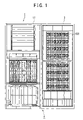
FIG. 4 is an elevation view of the storage control device 1;
FIG. 5 is a sectional view of the storage control device taken in a plane shown by arrows 5-5 in FIG. 4;
FIG. 6A is a figure showing a structural example of a NAS unit 5;
FIG. 6B is a figure showing this NAS unit 5 as seen from above;
FIG. 7A is a figure showing the air flow in a third section 9, and a structural example of a power supply sub-box 25, in more detail;
FIG. 7B is a figure showing an example of an elevation view of the power supply sub-box 25;
FIG. 8 is a block diagram showing an example of the structure of the storage device system 4; and
FIG. 9 is an explanatory figure showing an example of a cooling control method for a second embodiment of the present invention.
DESCRIPTION OF THE PREFERRED EMBODIMENTS
In the following, various preferred embodiments of the storage control device according to the present invention will now be explained with reference to the figures.
Embodiment 1
FIG. 1 is an elevation view of an example of a storage device system incorporating a storage control device according to the first embodiment of the present invention.
The storage device system 4 comprises a storage control device 1 which controls a storage device 150. This storage control device 1 may be constructed using a chassis 11. And the storage device 150 may be mounted on another chassis 3. In the following, for convenience, the chassis 11 will be termed the “main chassis 11”, and the chassis 3 will be termed the “extension chassis 3”.
A plurality of storage devices 150 may be mounted in the extension chassis 3, so as to be arrayed along both the width direction and the vertical direction of the extension chassis 3. These storage devices 150 may be of any types, and, in this first embodiment, hard disk drives may be employed. The storage devices 150 are shaped as rectangular parallelepipeds, and may be mounted vertically (in other words, upright (or the storage devices 150 may be mounted horizontally, in other words on their sides). This type of extension chassis 3 is not limited to being one in number; two or more may also be fitted. By doing this, it is possible to increase the storage capacity of the storage device system 4.
It should be understood that the upper surfaces, the lower surfaces, and the side surfaces of the extension chassis 3 and the main chassis 11 may be closed, while their front and rear surfaces may be opened, so as to constitute a casing. Furthermore, although this feature is not shown in the figure, cover plates may be provided on the front surface and/or the rear surface of at least one of the extension chassis 3 and the main chassis 11, so as substantially entirely to cover this surface. Air passage portions may be provided in these cover plates for sucking in air from the exterior of the storage device system 4 to its interior, or for expelling air from the interior of the storage device system 4 to the exterior. These air passage portions may, for example, consist of a large number of holes.
FIG. 2 is a perspective view of the storage control device 1 as seen from its front. FIG. 3 is a perspective view of the storage control device 1 as seen from its rear. FIG. 4 is an elevation view of the storage control device 1. And FIG. 5 is a sectional view of the storage control device 1 taken in a plane shown by the arrows 5-5 in FIG. 4.
The main chassis 11 is substantially a rectangular parallepiped, and may be divided, from above to below, into a first section 7, a second section 8, and a third section 9. A boundary member (for example a plate) is provided between each section and the neighboring section, for partitioning them from one another.
The first section 7 may be considered as a section in which plate shaped NAS units 15 are mounted (these NAS units 15 will be explained hereinafter). In concrete terms, for example, a NAS box 10 and a NAS back plane 13 may be provided in this first section 7. This NAS box 10 is substantially a rectangular parallelepiped, and at least its surface which faces the front surface of the storage control device 1 is opened. The NAS units 15 are inserted into this NAS box 10 from this surface thereof, and they may be connected to the NAS back plane 13 by being inserted further thereinto in the depthwise direction. This NAS back plane 13 may be, for example, a circuit board on which printed wiring has been formed.
Furthermore, in the first section 7, there may be provided a maintenance terminal 17 (sometimes, by abbreviating “Service Processor”, this is termed a SVP) which can be shifted forward and backward in the depthwise direction of the storage control device 1. This maintenance terminal 17 (hereinafter termed a SVP) is, for example, a notebook type personal computer. The SVP 17 may comprise, for example, a control unit (for example, a motherboard on which are mounted a CPU and the like) and an input device (for example, a keyboard). This control unit of the SVP 17 may be provided in the interior of the storage control device 1, and, in the position of the SVP 17, instead of the SVP 17, there may be provided an input device for actuating this control unit. As for its position, the height from the floor surface at which the storage control device 1 is set up may be set to a height at which the user can easily input information using the input device. In concrete terms, for example, this height may be set in the range from 1 m 20 cm to 1 m 30 cm. The SVP 17 may be mounted lower than the plurality of NAS units 15.
Furthermore, spaces 31 for allowing the flow of air (hereinafter termed air flow conduit spaces) are provided in the first section 7, between the plurality of NAS units 15 and the side surfaces of the storage control device 1. In concrete terms, for example, an air flow conduit space 31 is provided at one side at least of both of the sides of the plurality of NAS units 15 (for example at the NAS box 10). Although these air flow conduit spaces 31 may, for example, simply be gaps between the plurality of NAS units 5 and the sides of the storage control device 1, by, as in this embodiment, plates (for example, the sides of the NAS box 10) being provided so as to constitute partitions between the plurality of NAS units 5 and the air flow conduit spaces 31, it is possible to prevent the air which is flowing in these air flow conduit spaces 31 from exerting influence on the cooling of the NAS units 5 (the sides of the NAS box 10 may also, for example, be made from an insulating material). These air flow conduit spaces 31 connect from the lower surface of the first section 7 to the upper surface of the storage control device 1. The air which has entered from the lower surface of the first section 7 into these air flow conduit spaces 31 rises within these spaces 31 and is expelled from the upper surface of the storage control device 1. It should be understood that the air exhaust outlets from the air flow conduit spaces 31 are not limited to being on the upper surface of the storage control device 1; for example, it would also be possible to provide them on the rear surface of the storage control device 1. In this case, the air which has entered into the air flow conduit spaces 31 and has risen therein curves toward the rear enroute, and is expelled from the rear surface of the storage control device 1. These air flow conduit spaces 31 may be, for example, provided-using so called dead space of the first section 7.
In the second section 8, there are comprised a logic box 20, a fan mounting stand 35, and one or a plurality of logic fans 19, 19, . . . .
The logic box 20 is substantially a rectangular parallelepiped, and its surfaces which face the front surface and the rear surface of the storage control device 1 are open. A logic back plane 41 is provided in approximately the middle of the logic box 20, so as to partition the space within the logic box 20 into a front side and a rear side. This logic back plane 41 may be, for example, a circuit board on which printed wiring is formed.
From both the front surface and its rear surface of the logic box 20, logical substrates 21 are inserted within the logic box 20 and are set vertically (i.e. upright) therein, and these logical substrates 21 are connected to both the sides of the logic back plane 41. The logical substrates 21 may be connected so as to be lined up in the width direction of the storage control device 1. In this plurality of logical substrates 21 there may be included, for example, at least one of a disk adapter described hereinafter, a channel adapter, a cache memory, and a common memory.
The fan mounting stand 35 is provided above the logic box 20, and the logic fans 19, 19, . . . are set up on this fan mounting stand 35. One or a plurality of openings (for example holes or slits) may be provided in the upper surface of the logic box 20, or in the fan mounting stand 35, so as to allow air which is sucked in by the logic fans 19, 19, . . . to flow freely.
Furthermore, a certain space is provided in the second section 8 above the logic fans 19, 19, . . . , and this space joins to the above described air flow conduit spaces 31, via the boundary between the first section 7 and the second section 8. In concrete terms, for example, openings 38 (for example holes or slits) are provided at the boundary between the first section 7 and the second section 8, as shown by the dotted lines, and the air which has been expelled from the logic fans 19 can flow into the air flow conduit spaces 31 via these openings 38. It should be understood that, in this second section 8, as shown by the dotted lines, there may be provided flow regulating plates 34 for causing the air which has been expelled from the logic fans 19 to flow into the openings 38 in a smooth manner. Furthermore, instead of or as well as these, various types of guide member may also be provided.
A power supply box 30 is provided in the third section 9. This power supply box 30 is substantially a rectangular parallelepiped, and its sides which face the front surface and the rear surface of the storage control device 1 are open. A power supply back plane 67 is provided in approximately the center of this power supply box 30, so as to partition the space within the power supply box 30 into a front side and a rear side. This power supply back plane 67 may be, for example, a circuit board on which printed wiring has been formed.
Plate shaped batteries 23 are inserted into the power supply box 30 from the front surface of the power supply box 30, and are set up vertically (i.e. upright) therein, and these batteries 23 are connected to one surface of the power supply back plane 67. Furthermore, block shaped power supply sub-boxes 25 are inserted into the power supply box 30 from the rear surface of the power supply block 30, and these power supply sub-boxes 25 are connected to the other surface of the power supply back plane 67.
As described above, in this first embodiment, the subjects for cooling of the same type among the plurality of types of subject for cooling are grouped together, and various sections which correspond to these various groups of types of subjects for cooling are provided to the storage control device 1, with the various groups of types of subjects for cooling being mounted to the sections which correspond to them. In concrete terms, the NAS units 15 comprising NAS head substrates described hereinafter, which are one type of subject for cooling, are mounted in the first section; the logical substrates 21, which are another type of subject for cooling, are mounted in the second section; and the power supply sub-boxes 25 which comprise power supplies, which are yet another type of subject for cooling, are mounted in the third section.
In this first embodiment, the flows of air which cool the subjects for cooling are made to be independent for each of the sections (or, to put it in another manner, for each of the groups of a type of subject for cooling). In other words, the storage control device 1 is so structured, that the air which cools each of the types of subject for cooling does not exert any substantial influence on the cooling of the subjects for cooling of the other types.
In the following, the cooling of the storage control device 1 will be explained in concrete terms with reference to FIGS. 2 through 5. It should be understood that an outline of the flow of air is shown by the thick arrow signs in FIGS. 2 through 5, in order to make it easier to explain the essentials of the air flow. However, the flow of air is not necessarily limited to being as shown by the arrow signs. For example, stagnant pools in the flow of air are caused due to the various members in the storage control device 1 and their temperatures and so on, and the effect thereof is that the air does not flow in straight lines. In concrete terms, although, for example, the arrow signs for the second section 8 indicate that the air which has been sucked in from under the second section 8 turns through a right angle and flows upwards, this is simply for showing that the air which has been sucked in from the lower side of the second section 8 rises and is expelled from the logic fans 19.
Air is sucked into the first section 7 via its front surface from the exterior of the storage control device 1 of, and this sucked in air passes through the NAS units 15 and is expelled from the rear surface of the storage control device 1 to its exterior. In concrete terms, for example, as shown in the example of FIG. 6A, within a NAS unit 15 there are comprised a NAS head substrate 110E, a fan unit 51 which comprises one or more fans (hereinafter termed NAS fans) 53 for cooling the NAS head substrate 110E, and a power supply 55 and a battery 57 for the NAS head substrate 110E and/or the NAS fans 53. The front surface and the rear surface of the NAS unit 15 are made so that air can pass through them (for example, air intake apertures 1001 and air exhaust apertures 1003 may be provided in the front surface and the rear surface). Air is sucked in by the NAS fans 53 from the exterior of the storage control device 15 via its front surface, and this sucked in air is sucked into the NAS unit 15 via the front surface of the NAS unit 15, and this sucked in air flows over the surface of the NAS head substrate 110E and is expelled from the rear surface of the NAS unit 15, with this expelled air being then expelled to the exterior of the storage control device 1 from its rear surface. Since, due to this, the air which has been sucked into the storage control device 1 flows over the NAS head substrate 110E (in particular, for example, over a heat generating portion mounted to this substrate 110E, for example a CPU or a heat sink), accordingly it is able to cool the NAS head substrate 110E (in particular, for example, its heat generation portion). It should be understood that the NAS fans 53 may be fitted more to the front side than the NAS head substrate 110E, as shown in the figure; or, although this is not shown in the figure, they may be fitted more to the rear side than the NAS head substrate 110E.
In the second section 8, air is sucked in from the exterior of the storage control device 1 through its front surface, and, among this sucked in air, the air in the vicinity of the lower portion of the second section 8 rises while progressing through the middle of the storage control device 1, and this air which has risen up is expelled from the second section 8 to the exterior of the storage control device 1. In concrete terms, for example, the air is sucked in by the logic fans 19 from the exterior of the storage control device 15 via its front surface, and, among this sucked in air, the air in the vicinity of the lower portion of the second section 8 rises while progressing through the middle of the storage control device 1, and this air which has risen up is sucked by the logic fans 19 and is expelled upwards therefrom, and this expelled air flows via the holes 38 provided in the division between the first section 7 and the second section 8 into the air flow conduit spaces 31, and is then expelled to the exterior of the storage control device 1. Since, due to this, the air which has been sucked into the storage control device 1 flows over the logical substrates 21 (in particular, for example, over heat generating portions mounted to these logical substrates 21, for example CPUs or heat sinks), accordingly it is able to cool the logical substrates 2l (in particular, for example, their heat generation portions).
In the third section 9, air is sucked in from the exterior of the storage control device 1 through its front surface, and this sucked in air passes through the power supply sub-boxes 25 and is expelled from the rear surface of the storage control device 1 to its exterior. In concrete terms, for example, as shown in the example of FIG. 7A, within each of the power supply sub-boxes 25 there are provided a power supply 26 and one or more fans (hereinafter termed power supply fans 63) for cooling this power supply 26. These power supply fans 63 may be provided more toward the rear side (or toward the front side) than the power supply 26. As shown in the example of FIG. 7B, by providing a large number of openings (for example holes) 69 on the front surface (and the rear surface) of the power supply sub-boxes 25, it is arranged for air to be sucked from the front surface of the power supply sub-boxes 25 into their interiors. Thus, air is sucked in from the exterior of the storage control device 15 through its front surface by the power supply fans 63, and this sucked in air is sucked into the interior of the power supply sub-boxes 25 via the front surface of the power supply sub-boxes 25, with the sucked in air then flowing over the outer surfaces of the power supplies 26 and then being expelled from the rear surface of the power supply sub-boxes 25, this expelled air then being expelled from the rear surface of the storage control device 1. Since, by doing this, it is possible for the air which has been sucked into the storage control device 1 to flow over the power supplies 26, accordingly it is possible to cool the power supplies 26. It should be understood that, in this first embodiment, the air which has been sucked in from the front surface of the storage control device 1 proceeds as far as the vicinity of the center of the storage control device 1 by passing underneath the batteries 23, and this air is then directed upwards by the guides 65 which are provided in this central vicinity, so that this air which has risen upwards may be sucked in from the front surfaces of the power supply sub-boxes 25. Since, due to this, it is possible to cool the power supplies 26 with air at a lower temperature than air which has passed past the batteries 23 and has been heated up thereby, accordingly it is possible to suppress deterioration of the cooling efficiency for the power supplies 26.
The above is an explanation of the cooling of this storage control device 1 according to the first embodiment.
Next, examples of the structure and function of the storage device system 4 to which this storage control device 1 is fitted will be described in the following.
FIG. 8 is a block diagram showing an example of the structure of the storage device system 4.
This storage device system 4 may, for example, perform storage control according to the RAID (Redundant Array of Independent Disks) method. One or a plurality of RAID groups 210 are fitted within an extension chassis 3. NAS head substrates 110E, one or a plurality of disk adapters 120 (hereinafter termed DKAs), a cache memory 130, a common memory 140, and a switching control unit 270 may be comprised in the storage control device 1.
The RAID groups 210 comprise a plurality of storage devices 150, and provide redundant storage based on a RAID method such as, for example, RAID1 or RAID5 or the like. Each of the storage devices 150 may itself be, for example, a hard disk drive, or may be a device which comprises a hard disk drive within a canister (not shown in the figure). At least one or more logical volumes 6 (hereinafter termed VOLs), which are logical storage regions, may be provided on the physical storage region provided by each of the storage devices 150. A plurality of data items transmitted from a host device 180 may be stored in a VOL 6.
Each of the DKAs 120 is a device which controls data transfer to and from the storage devices 150. These DKAs 120, for example, may be made as micro computer systems including a CPU, ROM, RAM, and the like. A plurality of the DKAs 120 may, for example, be provided within this storage device system 4. Each of the DKAs 120 is able to read out block level data from the cache memory 130 and to write it into the storage devices 150, and to write block level data which it has read out from the storage devices 150 into the cache memory 130.
Each of the NAS head substrates 110E may function as a NAS head. Each of the NAS head substrates 110E receives data from the host device 180 via a connection path 190. This connection path 190 may be a communication network, or may be a dedicated path line. Each of the NAS head substrates 110E may be made as a micro computer system, in the same manner as the DKAs 120. For example, a NAS head substrate 110E may comprise a first CPU which receives file level data from the host device 180 and converts it to block level data, and a second CPU which outputs this block level data after conversion to the cache memory 130.
The cache memory 130 may be made using, for example, volatile or non-volatile semiconductor memory. This cache memory 130 is able to store data from the host device 180, or data which has been read out from a VOL 6.
The common memory 140 may be made using, for example, volatile or non-volatile semiconductor memory. This common memory 140 stores various types of command which it has received from the host device 180, or control information or the like which is used for control of the storage device system 4. This command or control information or the like maybe redundantly stored in a plurality of common memories 140. It should be understood that the cache memory 130 and the common memory 140 may be made as individually separate memories, or may also be made so as to use one portion of a memory as a cache memory region, and another portion of the same memory as a common memory region.
The switching control unit 270, the DKAs 120, the NAS head substrates 110E, the cache memory 130, and the common memory 140 are all mutually connected together. The switching control unit 270, for example, may comprise an ultra high speed crossbar switch or the like.
An SVP 17 is able to collect and to monitor the states of the various sections within the storage device system 4 via, for example, an interior network 282 such as a LAN. This SVP 17 is able to output information about these internal states which it has collected at an external management terminal (not shown in the figure) as raw data just as it is, or as statistically processed data. Furthermore, the SVP 17 is able to receive input of information, to store information which has been inputted in a predetermined storage region (for example a memory) comprised within itself, and to transmit it to the NAS head substrates 110E or to the DKAs 120.
The above concludes the explanation of the first embodiment. It should be understood that, in addition to the NAS head substrates 110E, there may also be provided a channel adapter (hereinafter termed a CHA) which controls communication with the host device 180. Such a CHA may, for example, receive block level data from the host device 180, and write this block level data into the cache memory 130. In this case, the above described logical substrates 21 may constitute the CHA, the DKA 120, the cache memory 130, and the common memory 140.
According to the above described first embodiment, the flows of air which cool the subjects for cooling in each of the sections (to put it in another manner, in each of the groups of a type of subjects for cooling) are made to be independent. In other words, the storage control device 1 is built so that the air which cools the subjects for cooling of each of the various types does not exert any substantial influence on the cooling of the subjects for cooling of the other types. By doing this, it is possible to cool each of the types of subject for cooling in the storage control device 1 in an efficient manner. In concrete terms, for example, it is possible to make the degree of cooling for each of the various different types of subject for cooling different (i.e. to perform temperature control).
Moreover, according to the above described first embodiment, the air flow conduits for each of the various groups of a type of subject for cooling are independent (in other words, the flow conduits are not gathered together), and fans are provided separately for each of the various groups of a type of subject for cooling. Due to this, it is possible to suppress the noise of the fans, since it is sufficient for each fan to be able to cool its own corresponding type of subject for cooling.
Furthermore, according to the above described first embodiment, the NAS head substrates 110E are mounted to a separate section 7 which is divided from the logical substrates 21, so that it may be cooled by a cooling mechanism (in this embodiment, the NAS fans 53) which is different from the cooling mechanism which cools the logical substrates 21 (in this embodiment, the logic fans 19). By doing this, it is possible to perform the cooling in an efficient manner.
Yet further, according to the above described first embodiment, the NAS head substrates 110E are also mounted in a position higher than that of the logical substrates 21. Since, normally, these NAS head substrates 110E are endowed with a higher speed function than the logical substrates 21, accordingly they generate higher temperatures than do the logical substrates 21. Due to this, the temperature of the air which has cooled the NAS head substrates 110E and is expelled to the exterior of the storage control device 1 is presumably higher than the temperature of the air which has cooled the logical substrates 21 and is expelled to the exterior of the storage control device 1. Consequently, if the NAS head substrates 110E were to be mounted in a position lower than that of the logical substrates 21, then it is considered that the air which has cooled the NAS head substrates 110E and is expelled to the exterior of the storage control device 1 and which rises might be sucked into the interior of the storage control device 1 in order to cool the logical substrates 21. In this case, the degree of cooling for the logical substrates 21 might become reduced. Thus by, as in this embodiment, mounting the NAS head substrates 110E in a position higher than that of the logical substrates 21, it is possible to ensure that the degree of cooling for the logical substrates 21 is not reduced.
Still further, according to the above described first embodiment, the plurality of logical substrates 21 are mounted in a position higher than that of the batteries 23 and the power supply sub-boxes 25, and the one or more NAS units 15 are mounted in a position which is still higher than that of the plurality of logical substrates 21. Although the user may demand any type of function from the storage control device 1, in any case, the NAS units 15 are not limited to being fitted so as to fill up the NAS box 10. Due to this, it is considered that the section to which the NAS units 15 are mounted will be lighter than the other sections. Therefore attention is paid, in this first embodiment, in order to make it possible to set up the storage control device 1 with good weight balance.
Even further, according to the above described first embodiment, it is possible to connect the back planes 13, 41, and 67 so that they are capable of communication with other back planes. Moreover, the logic back planes 41 are printed with wiring of a higher density than that of the NAS back planes 13 and the power supply back planes 67. Due to this, openings (for example, holes) are provided in the NAS back planes 13 and in the power supply back planes 67, and it is possible for air to pass through these back planes 13 and 67 via these openings; but it would be difficult to provide such openings in the logic back planes 41. Because of this it is effective to use the method, as in this first embodiment, of not piercing holes in the logic back planes 41 from their front sides to their rear sides, but instead of allowing the air to rise while following along the surfaces of these logic back planes 41.
Moreover, according to the above described first embodiment, air is not sucked in through or blown out through the side surfaces of the storage control device 1. Due to this, it is possible to provide an extension chassis at the side surface of the storage control device 1, so as closely to abut and contact it.
Embodiment Two
In the following, a second preferred embodiment of the present invention will be explained. Principally, at this time, the features of difference with the first embodiment will be explained, while explanation of features in common with the first embodiment will be curtailed or simplified.
In this second embodiment, the storage control device 1 is able to perform different types of cooling control separately for the various types of subject for cooling.
FIG. 9 is an explanatory figure showing an example of a cooling control method in this second embodiment of the present invention.
For example, temperature sensors 59A, 59B, and 59C are provided individually for each of the sections 7, 8, and 9. In concrete terms, for example, a temperature sensor 59A may be provided to each of the NAS units 15. Furthermore, for example, a temperature sensor 59B may be provided within a logic box 20, or in the vicinity of a logic fan 19. Yet further, a temperature sensor 59C may be provided within each of the power supply sub-boxes 25.
A cooling control unit 61 may be provided to the storage control device 1. This cooling control unit 61 may be a hardware circuit, or may be a computer program which is read into a CPU and is executed. The cooling control unit 61 may be, for example, a computer program which is read into and executed by a CPU of a NAS head substrate 110E, a CHA, or a DKA 120.
The cooling control unit 61 receives the temperature which is detected by the temperature sensors 59A, 59B, and 59C, and is able to perform cooling control of the various types of subject for cooling based on these temperatures.
In concrete terms, for example, the cooling control unit 61 is able to control the number of rotations per unit time of the NAS unit fans 53 within the NAS units 15, based on the temperature which has been detected by a temperature sensor 59A. If a plurality of the temperature sensors 59A are present, the cooling control unit 61 may determine within which NAS unit 15 to control the NAS fan 53, or which of the NAS fans 53 to control, according to which of the temperature sensors 59A has detected what temperature.
Furthermore, for example, the cooling control unit 61 may control the number of rotations per unit time of the logic fans 53, based on the temperature which has been detected by the temperature sensor 59B. At this time, the cooling control unit 61 may control the number of rotations per unit time of any one of the logic fans 53.
Moreover, for example, the cooling control unit 61 may control the number of rotations per unit time of the power supply fans 63 within the power supply sub-boxes 25, based on the temperatures which have been detected by the temperature sensors 59C. If a plurality of the temperature sensors 59C are present, the cooling control unit 61 may determine within which power supply sub-box 25 to control the power supply fan 63, according to which of the temperature sensors 59C has detected what temperature.
According to this second embodiment, it is possible to control the cooling separately for each of several subjects for cooling. Although the present invention has been described above in terms of certain preferred embodiments thereof, the present invention is not to be considered as being limited by those embodiments; various changes may be made to the present invention, provided that its scope is not departed from. For example, provided that the air flow conduits in each of the various separate groups of a type of subjects for cooling are independent, it would be acceptable to provide a common air sucking in aperture, or a common air exhaust outlet. Moreover, it would also be possible to mount the storage devices 150 in the first section 7, instead of the NAS units 15.

Claims (31)

1. A storage control device which controls a storage device, comprising:
M subjects for cooling including two or more groups of subjects for cooling,
wherein one of said two or more groups of subjects for cooling includes m subjects for cooling of the same type (where m is a integer greater than or equal to 2, and M>m); and
two or more cooling mechanisms which respectively correspond to said two or more groups of subjects for cooling,
wherein each cooling mechanism of said two or more cooling mechanisms is a mechanism for cooling the subjects for cooling included in the corresponding group of subjects for cooling, and is independent from other cooling mechanisms of said two or more cooling mechanisms,
wherein said two or more groups of subjects for cooling includes first, second, and third groups of subjects for cooling,
wherein first subjects for cooling which are cooled by a first cooling mechanism corresponding to said first group of subjects for cooling are NAS head substrates or storage devices,
wherein second subjects for cooling which are cooled by a second cooling mechanism corresponding to said second group of subjects for cooling are logical substrates which are separate from said NAS head substrates,
wherein third subjects for cooling which are cooled by a third cooling mechanism corresponding to said third group of subjects for cooling are power supplies,
wherein said storage control device is divided, from above to below, into a plurality of sections,
wherein said plurality of sections includes:
a first section in which a plurality of said NAS head substrates or said storage devices are mounted,
a second section in which a plurality of said logical substrates are mounted, and
a third section in which said power supplies are mounted,
wherein said NAS head substrates are mounted horizontally in said first section, and
wherein said first cooling mechanism sucks in air from the exterior of said storage control device via the front surface of said storage control device, and expels said sucked in air to the exterior of said storage control device from the rear surface of said storage control device.
2. The storage control device according to claim 1, wherein air is sucked into said storage control device by each of said cooling mechanisms of said two or more cooling mechanisms, and said sucked in air cools the subjects for cooling included in the corresponding group of subjects for cooling, and is then expelled to exterior of said storage control device, and
wherein the air flow conduit for each said cooling mechanism of said two or more cooling mechanisms is independent from air flow conduits for air sucked in by the other cooling mechanisms of said two or more cooling mechanisms.
3. The storage control device according to claim 2, wherein said cooling mechanisms of said two or more cooling mechanisms are provided so that air which has been expelled to the exterior of said storage control device by each of said cooling mechanisms, and whose temperature is higher than that of the sucked in air, is not sucked in by the other cooling mechanisms of said two or more cooling mechanisms.
4. The storage control device according to claim 1,
wherein each of the NAS head substrates is mounted horizontally, and moreover is provided with one or more NAS heads and a first fan for cooling said one or more NAS heads; and
wherein said first fan is provided more toward the front side, or the rear side, of said storage control device, than said one or more NAS heads.
5. The storage control device according to claim 1, wherein a first circuit board is provided in said first section, parallel or substantially parallel to the front surface of said storage control device,
wherein said NAS head substrates are oriented horizontally and connected to said first circuit board;
wherein on said first circuit board, the plurality of NAS head substrates are arranged along the height direction of said storage control device;
wherein a second circuit board is provided in said second section, parallel or substantially parallel to the front surface of said storage control device;
wherein said logical substrates are oriented vertically and connected to both surfaces of said second circuit board;
wherein on said second circuit board, the plurality of logical substrates are arranged along the width direction of said storage control device;
wherein a third circuit board is provided in said third section, parallel or substantially parallel to the front surface of said storage control device; and
wherein said power supplies are connected to said third circuit board.
6. A storage control device which controls a storage device, comprising:
M subjects for cooling including two or more groups of subjects for cooling,
wherein one of said two or more groups of subjects for cooling includes m subjects for cooling of the same type (where m is a integer greater than or equal to 2, and M>m); and
two or more cooling mechanisms which respectively correspond to said two or more groups of subjects for cooling,
wherein each cooling mechanism of said two or more cooling mechanisms is a mechanism for cooling the subjects for cooling included in the corresponding group of subjects for cooling, and is independent from other cooling mechanisms of said two or more cooling mechanisms,
wherein said two or more groups of subjects for cooling includes first, second, and third groups of subjects for cooling,
wherein first subjects for cooling which are cooled by a first cooling mechanism corresponding to said first group of subjects for cooling are NAS head substrates or storage devices,
wherein second subjects for cooling which are cooled by a second cooling mechanism corresponding to said second group of subjects for cooling are logical substrates which are separate from said NAS head substrates,
wherein third subjects for cooling which are cooled by a third cooling mechanism corresponding to said third group of subjects for cooling are power supplies,
wherein said storage control device is divided, from above to below, into a plurality of sections,
wherein said plurality of sections includes:
a first section in which a plurality of said NAS head substrates or said storage devices are mounted,
a second section in which a plurality of said logical substrates are mounted, and
a third section in which said power supplies are mounted,
wherein, in said first section, an input device for a user to input information to said storage control device is mounted so as to be shiftable both in the rearward direction and the forward direction of said storage control device.
7. The storage control device according to claim 6, wherein said input device is positioned at a height at which said user can easily input said information.
8. The storage control device according to claim 6, wherein air is sucked into said storage control device by each of said cooling mechanisms of said two or more cooling mechanisms, and said sucked in air cools the subjects for cooling included in the corresponding group of subjects for cooling, and is then expelled to exterior of said storage control device, and
wherein the air flow conduit for each said cooling mechanism of said two or more cooling mechanisms is independent from air flow conduits for air sucked in by the other cooling mechanisms of said two or more cooling mechanisms.
9. The storage control device according to claim 8, wherein said cooling mechanisms of said two or more cooling mechanisms are provided so that air which has been expelled to the exterior of said storage control device by each of said cooling mechanisms, and whose temperature is higher than that of the sucked in air, is not sucked in by the other cooling mechanisms of said two or more cooling mechanisms.
10. The storage control device according to claim 6, wherein a first circuit board is provided in said first section, parallel or substantially parallel to the front surface of said storage control device,
wherein said NAS head substrates are oriented horizontally and connected to said first circuit board;
wherein on said first circuit board, the plurality of NAS head substrates are arranged along the height direction of said storage control device;
wherein a second circuit board is provided in said second section, parallel or substantially parallel to the front surface of said storage control device;
wherein said logical substrates are oriented vertically and connected to both surfaces of said second circuit board;
wherein on said second circuit board, the plurality of logical substrates are arranged along the width direction of said storage control device;
wherein a third circuit board is provided in said third section, parallel or substantially parallel to the front surface of said storage control device; and
wherein said power supplies are connected to said third circuit board.
11. The storage control device according to claim 6, wherein a temperature sensor is provided to or in the vicinity of at least one of said first section, said second section, and said third section; and
wherein based on the temperature which has been detected by said temperature sensor, said NAS head substrates or said logical substrates control one of said first, second and third cooling mechanisms corresponding to said detected temperature.
12. The storage control device according to claim 6, wherein at least one of said first section, said second section, and said third section comprises a tubular box;
wherein a surface, which is a surface of said tubular box, and which is parallel to at least one of the front surface and the rear surface of said storage control device, is open; and
wherein a subject for cooling included in one of said two or more groups of subject for cooling is mounted via said open surface.
13. A storage control device which controls a storage device, comprising:
M subjects for cooling including two or more groups of subjects for cooling,
wherein one of said two or more groups of subjects for cooling includes m subjects for cooling of the same type (where m is a integer greater than or equal to 2, and M>m); and
two or more cooling mechanisms which respectively correspond to said two or more groups of subjects for cooling,
wherein each cooling mechanism of said two or more cooling mechanisms is a mechanism for cooling the subjects for cooling included in the corresponding group of subjects for cooling, and is independent from other cooling mechanisms of said two or more cooling mechanisms,
wherein said two or more groups of subjects for cooling includes first, second, and third groups of subjects for cooling,
wherein first subjects for cooling which are cooled by a first cooling mechanism corresponding to said first group of subjects for cooling are NAS head substrates or storage devices,
wherein second subjects for cooling which are cooled by a second cooling mechanism corresponding to said second group of subjects for cooling are logical substrates which are separate from said NAS head substrates,
wherein third subjects for cooling which are cooled by a third cooling mechanism corresponding to said third group of subjects for cooling are power supplies,
wherein said storage control device is divided, from above to below, into a plurality of sections,
wherein said plurality of sections includes:
a first section in which a plurality of said NAS head substrates or said storage devices are mounted,
a second section in which a plurality of said logical substrates are mounted, and
a third section in which said power supplies are mounted,
wherein said second section is positioned below said first section;
wherein in said second section, said plurality of said logical substrates are arranged along the width direction of said storage control device, with each of said logical substrates being mounted vertically,
wherein said second cooling mechanism sucks in air from exterior of said storage control device via at least one of the front surface and the rear surface of said storage control device, and blows said sucked in air from the lower side of said plurality of logical substrates to their tops; and
wherein a flow conduit is provided on at least one of the right side and the left side of said plurality of NAS head substrates, along which said air which has flowed to the tops of said plurality of logical substrates flows.
14. The storage control device according to claim 13, wherein—between said first section and said plurality of logical substrates, there is mounted a second fan which sucks in air from the lower side, where said plurality of logical substrates are present, and expels the air upwards; and
wherein the air which has been expelled by said second fan passes along said flow conduit which is provided on at least one of the right side and the left side of said plurality of NAS head substrates.
15. The storage control device according to claim 14, wherein a guide member is provided for guiding the air which has been expelled by said second fan to an inlet of said flow conduit.
16. The storage control device according to claim 13, wherein a temperature sensor is provided to or in the vicinity of at least one of said first section, said second section, and said third section; and
wherein based on the temperature which has been detected by said temperature sensor, said NAS head substrates or said logical substrates control one of said first, second and third cooling mechanisms corresponding to said detected temperature.
17. The storage control device according to claim 13, wherein at least one of said first section, said second section, and said third section comprises a tubular box;
wherein a surface, which is a surface of said tubular box, and which is parallel to at least one of the front surface and the rear surface of said storage control device, is open; and
wherein a subject for cooling included in one of said two or more groups of subject for cooling is mounted via said open surface.
18. The storage control device according to claim 13, wherein a first circuit board is provided in said first section, parallel or substantially parallel to the front surface of said storage control device,
wherein said NAS head substrates are oriented horizontally and connected to said first circuit board;
wherein on said first circuit board, the plurality of NAS head substrates are arranged along the height direction of said storage control device;
wherein a second circuit board is provided in said second section, parallel or substantially parallel to the front surface of said storage control device;
wherein said logical substrates are oriented vertically and connected to both surfaces of said second circuit board;
wherein on said second circuit board, the plurality of logical substrates are arranged along the width direction of said storage control device;
wherein a third circuit board is provided in said third section, parallel or substantially parallel to the front surface of said storage control device; and
wherein said power supplies are connected to said third circuit board.
19. A storage control device which controls a storage device, comprising:
M subjects for cooling including two or more groups of subjects for cooling,
wherein one of said two or more groups of subjects for cooling includes m subjects for cooling of the same type (where m is a integer greater than or equal to 2, and M>m); and
two or more cooling mechanisms which respectively correspond to said two or more groups of subjects for cooling,
wherein each cooling mechanism of said two or more cooling mechanisms is a mechanism for cooling the subjects for cooling included in the corresponding group of subjects for cooling, and is independent from other cooling mechanisms of said two or more cooling mechanisms,
wherein said two or more groups of subjects for cooling includes first, second, and third groups of subjects for cooling,
wherein first subjects for cooling which are cooled by a first cooling mechanism corresponding to said first group of subjects for cooling are NAS head substrates or storage devices,
wherein second subjects for cooling which are cooled by a second cooling mechanism corresponding to said second group of subjects for cooling are logical substrates which are separate from said NAS head substrates,
wherein third subjects for cooling which are cooled by a third cooling mechanism corresponding to said third group of subjects for cooling are power supplies,
wherein said storage control device is divided, from above to below, into a plurality of sections,
wherein said plurality of sections includes:
a first section in which a plurality of said NAS head substrates or said storage devices are mounted,
a second section in which a plurality of said logical substrates are mounted, and
a third section in which said power supplies are mounted, and
wherein said third cooling mechanism sucks in air from exterior of said storage control device via the front surface of said storage control device, and expels said sucked in air to the exterior of said storage control device from the rear surface of said storage control device.
20. The storage control device according to claim 19, wherein—in said third section, a subject for cooling separate from said power supplies is mounted on the front side of said storage control device, with said power supplies being mounted more to the rear side than said separate subject for cooling; and
wherein said third cooling mechanism cools said power supplies with air which has been sucked in from a different location than the location at which said separate subject for cooling is located.
21. The storage control device according to claim 19, wherein air is sucked into said storage control device by each of said cooling mechanisms of said two or more cooling mechanisms, and said sucked in air cools the subjects for cooling included in the corresponding group of subjects for cooling, and is then expelled to exterior of said storage control device, and
wherein the air flow conduit for each said cooling mechanism of said two or more cooling mechanisms is independent from air flow conduits for air sucked in by the other cooling mechanisms of said two or more cooling mechanisms.
22. The storage control device according to claim 21, wherein said cooling mechanisms of said two or more cooling mechanisms are provided so that air which has been expelled to the exterior of said storage control device by each of said cooling mechanisms, and whose temperature is higher than that of the sucked in air, is not sucked in by the other cooling mechanisms of said two or more cooling mechanisms.
23. The storage control device according to claim 19, wherein a first circuit board is provided in said first section, parallel or substantially parallel to the front surface of said storage control device,
wherein said NAS head substrates are oriented horizontally and connected to said first circuit board;
wherein on said first circuit board, the plurality of NAS head substrates are arranged along the height direction of said storage control device;
wherein a second circuit board is provided in said second section, parallel or substantially parallel to the front surface of said storage control device;
wherein said logical substrates are oriented vertically and connected to both surfaces of said second circuit board;
wherein on said second circuit board, the plurality of logical substrates are arranged along the width direction of said storage control device;
wherein a third circuit board is provided in said third section, parallel or substantially parallel to the front surface of said storage control device; and
wherein said power supplies are connected to said third circuit board.
24. The storage control device according to claim 19, wherein a temperature sensor is provided to or in the vicinity of at least one of said first section, said second section, and said third section; and
wherein based on the temperature which has been detected by said temperature sensor, said NAS head substrates or said logical substrates control one of said first, second and third cooling mechanisms corresponding to said detected temperature.
25. The storage control device according to claim 19, wherein at least one of said first section, said second section, and said third section comprises a tubular box;
wherein a surface, which is a surface of said tubular box, and which is parallel to at least one of the front surface and the rear surface of said storage control device, is open; and
wherein a subject for cooling included in one of said two or more groups of subject for cooling is mounted via said open surface.
26. A storage control device which controls a storage device, comprising:
M subjects for cooling including two or more groups of subjects for cooling,
wherein one of said two or more groups of subjects for cooling includes m subjects for cooling of the same type (where m is a integer greater than or equal to 2, and M>m); and
two or more cooling mechanisms which respectively correspond to said two or more groups of subjects for cooling,
wherein each cooling mechanism of said two or more cooling mechanisms is a mechanism for cooling the subjects for cooling included in the corresponding group of subjects for cooling, and is independent from other cooling mechanisms of said two or more cooling mechanisms,
wherein said two or more groups of subjects for cooling includes first, second, and third groups of subjects for cooling,
wherein first subjects for cooling which are cooled by a first cooling mechanism corresponding to said first group of subjects for cooling are NAS head substrates or storage devices,
wherein second subjects for cooling which are cooled by a second cooling mechanism corresponding to said second group of subjects for cooling are logical substrates which are separate from said NAS head substrates,
wherein third subjects for cooling which are cooled by a third cooling mechanism corresponding to said third group of subjects for cooling are power supplies,
wherein said storage control device is divided, from above to below, into a plurality of sections,
wherein said plurality of sections includes:
a first section in which a plurality of said NAS head substrates or said storage devices are mounted,
a second section in which a plurality of said logical substrates are mounted, and
a third section in which said power supplies are mounted,
wherein said second section is above said third section;
wherein said first section is above said second section;
wherein said NAS head substrates are mounted horizontally in said first section;
wherein said first cooling mechanism sucks in air from the exterior of said storage control device via the front surface of said storage control device, and expels said sucked in air to the exterior of said storage control device from the rear surface of said storage control device;
wherein said plurality of logical substrates are arranged in said second section along the width direction of said storage control device, and each of said logical substrates is mounted vertically;
wherein said second cooling mechanism sucks in air from the exterior of said storage control device via at least one of the front surface and the rear surface of said storage control device, and blows said sucked in air from the lower side of said plurality of logical substrates to their tops;
wherein a flow conduit is provided on at least one of the right side and the left side of said plurality of NAS head substrates, along which said air which has flowed to the tops of said plurality of logical substrates flows; and
wherein said third cooling mechanism sucks in air from the exterior of said storage control device via the front surface of said storage control device, and expels said sucked in air to the exterior of said storage control device from the rear surface of said storage control device.
27. The storage control device according to claim 26, wherein air is sucked into said storage control device by each of said cooling mechanisms of said two or more cooling mechanisms, and said sucked in air cools the subjects for cooling included in the corresponding group of subjects for cooling, and is then expelled to exterior of said storage control device, and
wherein the air flow conduit for each said cooling mechanism of said two or more cooling mechanisms is independent from air flow conduits for air sucked in by the other cooling mechanisms of said two or more cooling mechanisms.
28. The storage control device according to claim 27, wherein said cooling mechanisms of said two or more cooling mechanisms are provided so that air which has been expelled to the exterior of said storage control device by each of said cooling mechanisms, and whose temperature is higher than that of the sucked in air, is not sucked in by the other cooling mechanisms of said two or more cooling mechanisms.
29. The storage control device according to claim 26, wherein a temperature sensor is provided to or in the vicinity of at least one of said first section, said second section, and said third section; and
wherein based on the temperature which has been detected by said temperature sensor, said NAS head substrates or said logical substrates control one of said first, second and third cooling mechanisms corresponding to said detected temperature.
30. The storage control device according to claim 26, wherein at least one of said first section, said second section, and said third section comprises a tubular box;
wherein a surface, which is a surface of said tubular box, and which is parallel to at least one of the front surface and the rear surface of said storage control device, is open; and
wherein a subject for cooling included in one of said two or more groups of subject for cooling is mounted via said open surface.
31. A storage control device which controls a storage device, comprising:
a first section in which a plurality of NAS head substrates are mounted, arranged along the height direction of said storage control device, and each oriented horizontally;
a second section in which a plurality of logical substrates are mounted, arranged along the width direction of said storage control device, and each oriented vertically;
a third section in which power supplies are mounted;
a first fan for cooling said plurality of NAS head substrates;
a second fan for cooling said plurality of logical substrates;
a third fan for cooling said power supplies; and
a chassis which is shaped as a rectangular parallelepiped or substantially as a rectangular parallelepiped, in which said first section, said second section, said third section, said first fan, said second fan, and said third fan are provided,
wherein said second section is above said third section;
wherein said first section is above said second section;
wherein said first fan is a fan for sucking in air from the exterior of said storage control device via the front surface of said storage control device, and for expelling said sucked in air to the exterior of said storage control device from the rear surface of said storage control device;
wherein said second fan is a fan provided between said first section and said second section, and for sucking in air from the exterior of said storage control device via at least one of the front surface and the rear surface of said storage control device, and for blowing said sucked in air from the lower side of said plurality of logical substrates to their tops;
wherein a flow conduit is provided on at least one of the right side and the left side of said plurality of NAS head substrates, along which said air which has been expelled by said second fan flows, with said air passing along said flow conduit and being expelled to the exterior of said storage control device,
wherein said third fan is a fan for sucking in air from the exterior of said storage control device via the front surface of said storage control device, and for expelling said sucked in air to the exterior of said storage control device from the rear surface of said storage control devices, and
wherein the flow conduit for air blown by each of said first fan, said second fan, and said third fan is independent from the flow conduits for air blown by other fans.
US11/347,311 2005-12-02 2006-02-06 Storage control device Expired - Fee Related US7411787B2 (en)

Applications Claiming Priority (2)

Application Number Priority Date Filing Date Title
JP2005349891A JP4818700B2 (en) 2005-12-02 2005-12-02 Storage controller
JP2005-349891 2005-12-02

Publications (2)

Publication Number Publication Date
US20070127207A1 US20070127207A1 (en) 2007-06-07
US7411787B2 true US7411787B2 (en) 2008-08-12

Family

ID=37635930

Family Applications (1)

Application Number Title Priority Date Filing Date
US11/347,311 Expired - Fee Related US7411787B2 (en) 2005-12-02 2006-02-06 Storage control device

Country Status (4)

Country Link
US (1) US7411787B2 (en)
EP (1) EP1793384A3 (en)
JP (1) JP4818700B2 (en)
CN (1) CN1975919B (en)

Cited By (19)

* Cited by examiner, † Cited by third party
Publication number Priority date Publication date Assignee Title
US20060082263A1 (en) * 2004-10-15 2006-04-20 American Power Conversion Corporation Mobile data center
US20070243814A1 (en) * 2006-03-24 2007-10-18 Fujitsu Limited Enclosure unit and electronic apparatus
US20100118484A1 (en) * 2008-11-12 2010-05-13 Hitachi, Ltd. Storage Control Device
US20100245999A1 (en) * 2009-03-30 2010-09-30 Carlow Richard A Cart For 3D Glasses
US20110157811A1 (en) * 2009-06-26 2011-06-30 Shigeaki Tanaka Storage apparatus, storage controller for storage apparatus, chassis for storage controller
US20130100610A1 (en) * 2011-10-19 2013-04-25 Danfoss A/S Air duct arrangement for cooling a group of at least two heat producing modules
US20140001932A1 (en) * 2012-06-29 2014-01-02 Nathan L. Westby Modular Outdoor Enclosure and Gravity Damper System
US20140340845A1 (en) * 2013-05-15 2014-11-20 DY 4 Systems, Inc. Fluid Cooled Enclosure For Circuit Module Apparatus And Methods Of Cooling A Conduction Cooled Circuit Module
US9215831B2 (en) 2012-11-22 2015-12-15 Huawei Technologies Co., Ltd. Heat dissipation system
US10240615B1 (en) 2017-09-23 2019-03-26 Facebook, Inc. Apparatus, system, and method for dampening vibrations generated by exhaust fans
US10349554B2 (en) * 2017-08-29 2019-07-09 Facebook, Inc. Apparatus, system, and method for directing air in a storage-system chassis
US10372360B2 (en) 2017-09-01 2019-08-06 Facebook, Inc. Apparatus, system, and method for reconfigurable media-agnostic storage
US10429911B2 (en) 2017-09-07 2019-10-01 Facebook, Inc. Apparatus, system, and method for detecting device types of storage devices
US10537035B2 (en) 2017-09-06 2020-01-14 Facebook, Inc. Apparatus, system, and method for securing hard drives in a storage chassis
US10558248B2 (en) 2017-09-09 2020-02-11 Facebook, Inc. Apparatus, system, and method for indicating the status of and securing hard drives
US10588238B2 (en) 2017-09-18 2020-03-10 Facebook, Inc. Apparatus, system, and method for partitioning a storage-system chassis
US10687435B2 (en) 2017-08-28 2020-06-16 Facebook, Inc. Apparatus, system, and method for enabling multiple storage-system configurations
US10736228B2 (en) 2017-08-31 2020-08-04 Facebook, Inc. Removeable drive-plane apparatus, system, and method
US10757831B2 (en) 2017-09-26 2020-08-25 Facebook, Inc. Apparatus, system, and method for reconfiguring air flow through a chassis

Families Citing this family (18)

* Cited by examiner, † Cited by third party
Publication number Priority date Publication date Assignee Title
JP4898598B2 (en) 2007-08-28 2012-03-14 株式会社日立製作所 Cooling structure of rack mount type control device and rack type storage control device
JP2009059033A (en) 2007-08-30 2009-03-19 Hitachi Ltd Storage controller
US20090266511A1 (en) * 2008-04-29 2009-10-29 Rob Yang Methods and systems for using a storage device to control and manage external cooling devices
JP2009288878A (en) * 2008-05-27 2009-12-10 Hitachi Ltd Storage device and cooling method thereof
JP4950968B2 (en) * 2008-09-01 2012-06-13 株式会社日立製作所 Storage device
TW201121395A (en) * 2009-12-03 2011-06-16 Hon Hai Prec Ind Co Ltd Server heat dissipation device and fan module thereof
US20110317351A1 (en) * 2010-06-23 2011-12-29 International Business Machines Corporation Server drawer
US8645767B2 (en) 2010-06-23 2014-02-04 International Business Machines Corporation Scalable I/O adapter function level error detection, isolation, and reporting
US8918573B2 (en) 2010-06-23 2014-12-23 International Business Machines Corporation Input/output (I/O) expansion response processing in a peripheral component interconnect express (PCIe) environment
US9036342B2 (en) * 2012-10-18 2015-05-19 Hitachi, Ltd. Storage apparatus and storage controller of storage apparatus
CN103841792B (en) * 2012-11-22 2017-04-12 华为技术有限公司 Cooling system
CN203691803U (en) * 2013-12-27 2014-07-02 中兴通讯股份有限公司 Plug-in box and terminal
US9949407B1 (en) * 2015-05-29 2018-04-17 Amazon Technologies, Inc. Computer system with partial bypass cooling
US10321608B1 (en) * 2015-12-14 2019-06-11 Amazon Technologies, Inc. Coordinated cooling using rack mountable cooling canisters
US9968005B2 (en) * 2016-03-08 2018-05-08 Quanta Computer, Inc. Different HDD gap architecture to reduce upstream preheat for high-density storage
US10856436B2 (en) * 2019-01-31 2020-12-01 Seagate Technology Llc Multilevel enclosure cooling
JP7065908B2 (en) * 2020-06-16 2022-05-12 株式会社日立製作所 Storage device
US11550370B2 (en) 2020-10-30 2023-01-10 Seagate Technology Llc Modular data storage systems

Citations (10)

* Cited by examiner, † Cited by third party
Publication number Priority date Publication date Assignee Title
US4774631A (en) * 1984-11-15 1988-09-27 Fujitsu Limited Cooling structure of electronic equipment rack
US5136464A (en) * 1990-04-20 1992-08-04 Kabushiki Kaisha Toshiba Housing structure for housing a plurality of electric components
US5544012A (en) * 1993-12-28 1996-08-06 Kabushiki Kaisha Toshiba Cooling system for cooling electronic apparatus
JPH08273345A (en) 1995-03-31 1996-10-18 Hitachi Ltd Magnetic disc drive
JP2001307474A (en) 2000-04-26 2001-11-02 Hitachi Ltd Disk device
JP2002232177A (en) 2001-02-05 2002-08-16 Jonan Kogyo Kk Shielding structure for electronic unit case
US20040264131A1 (en) * 2003-06-24 2004-12-30 Hitachi, Ltd. Cooling structure for electronic devices
US20050286221A1 (en) * 2004-06-23 2005-12-29 Shunsuke Yamana Storage device system and cooling structure for logic circuit board for storage device system
US20060139880A1 (en) * 2004-12-27 2006-06-29 Alan Tate Integrated circuit cooling system including heat pipes and external heat sink
US7133282B2 (en) * 2004-05-19 2006-11-07 Hitachi, Ltd. Disk array device

Family Cites Families (10)

* Cited by examiner, † Cited by third party
Publication number Priority date Publication date Assignee Title
JPH0756654A (en) * 1993-08-23 1995-03-03 Hitachi Ltd Information processor
JPH0793045A (en) * 1993-09-28 1995-04-07 Fujitsu Ltd Input/output device for computer
US5813243A (en) * 1997-04-04 1998-09-29 Micron Electronics, Inc. Chambered forced cooling system
JP2000187975A (en) * 1998-12-22 2000-07-04 Nec Corp Disk array device
JP2001307330A (en) * 2000-04-19 2001-11-02 Hitachi Ltd Optical disk system and control method thereof
US6445581B1 (en) * 2000-07-12 2002-09-03 Nstor Corporation Disk drive storage enclosure with isolated cooling path for storage media
JP4012091B2 (en) * 2003-02-20 2007-11-21 富士通株式会社 Electronic device cooling structure and information processing apparatus
US6819563B1 (en) * 2003-07-02 2004-11-16 International Business Machines Corporation Method and system for cooling electronics racks using pre-cooled air
JP4274916B2 (en) * 2003-11-28 2009-06-10 株式会社日立製作所 Disk array device
JP2005293370A (en) * 2004-04-01 2005-10-20 Hitachi Ltd Storage control system

Patent Citations (10)

* Cited by examiner, † Cited by third party
Publication number Priority date Publication date Assignee Title
US4774631A (en) * 1984-11-15 1988-09-27 Fujitsu Limited Cooling structure of electronic equipment rack
US5136464A (en) * 1990-04-20 1992-08-04 Kabushiki Kaisha Toshiba Housing structure for housing a plurality of electric components
US5544012A (en) * 1993-12-28 1996-08-06 Kabushiki Kaisha Toshiba Cooling system for cooling electronic apparatus
JPH08273345A (en) 1995-03-31 1996-10-18 Hitachi Ltd Magnetic disc drive
JP2001307474A (en) 2000-04-26 2001-11-02 Hitachi Ltd Disk device
JP2002232177A (en) 2001-02-05 2002-08-16 Jonan Kogyo Kk Shielding structure for electronic unit case
US20040264131A1 (en) * 2003-06-24 2004-12-30 Hitachi, Ltd. Cooling structure for electronic devices
US7133282B2 (en) * 2004-05-19 2006-11-07 Hitachi, Ltd. Disk array device
US20050286221A1 (en) * 2004-06-23 2005-12-29 Shunsuke Yamana Storage device system and cooling structure for logic circuit board for storage device system
US20060139880A1 (en) * 2004-12-27 2006-06-29 Alan Tate Integrated circuit cooling system including heat pipes and external heat sink

Cited By (25)

* Cited by examiner, † Cited by third party
Publication number Priority date Publication date Assignee Title
US20060082263A1 (en) * 2004-10-15 2006-04-20 American Power Conversion Corporation Mobile data center
US20070243814A1 (en) * 2006-03-24 2007-10-18 Fujitsu Limited Enclosure unit and electronic apparatus
US20100118484A1 (en) * 2008-11-12 2010-05-13 Hitachi, Ltd. Storage Control Device
US7911788B2 (en) * 2008-11-12 2011-03-22 Hitachi, Ltd. Storage control device
US20100245999A1 (en) * 2009-03-30 2010-09-30 Carlow Richard A Cart For 3D Glasses
US20110157811A1 (en) * 2009-06-26 2011-06-30 Shigeaki Tanaka Storage apparatus, storage controller for storage apparatus, chassis for storage controller
US8248782B2 (en) * 2009-06-26 2012-08-21 Hitachi, Ltd. Storage apparatus, storage controller for storage apparatus, chassis for storage controller
US20120281350A1 (en) * 2009-06-26 2012-11-08 Shigeaki Tanaka Storage apparatus, storage controller for storage apparatus, chassis for storage controller
US8879248B2 (en) * 2009-06-26 2014-11-04 Hitachi, Ltd. Storage apparatus, storage controller for storage apparatus, chassis for storage controller
US20130100610A1 (en) * 2011-10-19 2013-04-25 Danfoss A/S Air duct arrangement for cooling a group of at least two heat producing modules
US20140001932A1 (en) * 2012-06-29 2014-01-02 Nathan L. Westby Modular Outdoor Enclosure and Gravity Damper System
US9215831B2 (en) 2012-11-22 2015-12-15 Huawei Technologies Co., Ltd. Heat dissipation system
US9526191B2 (en) * 2013-05-15 2016-12-20 Dy 4 Systems Inc. Fluid cooled enclosure for circuit module apparatus and methods of cooling a conduction cooled circuit module
US20140340845A1 (en) * 2013-05-15 2014-11-20 DY 4 Systems, Inc. Fluid Cooled Enclosure For Circuit Module Apparatus And Methods Of Cooling A Conduction Cooled Circuit Module
US10687435B2 (en) 2017-08-28 2020-06-16 Facebook, Inc. Apparatus, system, and method for enabling multiple storage-system configurations
US11032934B1 (en) 2017-08-28 2021-06-08 Facebook, Inc. Apparatus, system, and method for enabling multiple storage-system configurations
US10349554B2 (en) * 2017-08-29 2019-07-09 Facebook, Inc. Apparatus, system, and method for directing air in a storage-system chassis
US10736228B2 (en) 2017-08-31 2020-08-04 Facebook, Inc. Removeable drive-plane apparatus, system, and method
US10372360B2 (en) 2017-09-01 2019-08-06 Facebook, Inc. Apparatus, system, and method for reconfigurable media-agnostic storage
US10537035B2 (en) 2017-09-06 2020-01-14 Facebook, Inc. Apparatus, system, and method for securing hard drives in a storage chassis
US10429911B2 (en) 2017-09-07 2019-10-01 Facebook, Inc. Apparatus, system, and method for detecting device types of storage devices
US10558248B2 (en) 2017-09-09 2020-02-11 Facebook, Inc. Apparatus, system, and method for indicating the status of and securing hard drives
US10588238B2 (en) 2017-09-18 2020-03-10 Facebook, Inc. Apparatus, system, and method for partitioning a storage-system chassis
US10240615B1 (en) 2017-09-23 2019-03-26 Facebook, Inc. Apparatus, system, and method for dampening vibrations generated by exhaust fans
US10757831B2 (en) 2017-09-26 2020-08-25 Facebook, Inc. Apparatus, system, and method for reconfiguring air flow through a chassis

Also Published As

Publication number Publication date
JP4818700B2 (en) 2011-11-16
EP1793384A3 (en) 2009-02-18
CN1975919A (en) 2007-06-06
EP1793384A2 (en) 2007-06-06
US20070127207A1 (en) 2007-06-07
JP2007156751A (en) 2007-06-21
CN1975919B (en) 2010-12-08

Similar Documents

Publication Publication Date Title
US7411787B2 (en) Storage control device
JP4360859B2 (en) Electronics
US7701710B2 (en) Cooling structure for rackmount-type control device and rack-type storage control device
US7766733B2 (en) Storage control apparatus equipped with a logic board for carrying out storage control
US7885062B2 (en) Computer chassis with partitions for improved airflow
US8300409B2 (en) Fan duct for electronic components of electronic device
US20130258580A1 (en) Storage apparatus and partition board used in storage apparatus
US7436663B2 (en) Disk array system
US20150305206A1 (en) Storage apparatus and storage controller of storage apparatus
US20060187634A1 (en) Disk device
US6563704B2 (en) Storage device arrangement for increased cooling
US6975509B2 (en) Computing apparatus with cooling fan
WO2002009113A1 (en) Disk array unit
US20180352679A1 (en) Memory device carrier for high density front serviceable rack drive chassis
US7782615B1 (en) Electronic device and cooling system thereof
EP2444753A2 (en) Air-conditioning system
JP4821679B2 (en) Magnetic disk module and aggregate disk device
US20090059522A1 (en) Storage control device
US20100159816A1 (en) Converging segments cooling
US10045465B2 (en) Container for electronic device and relay device
US10251315B1 (en) Apparatuses and methods for cooling high density arrays of non-volatile memory mass storage devices
CN115568153A (en) Server
CN109710043B (en) Computer heat abstractor
JP2018063984A (en) Electronic device cooling unit

Legal Events

Date Code Title Description
AS Assignment

Owner name: HITACHI, LTD., JAPAN

Free format text: ASSIGNMENT OF ASSIGNORS INTEREST;ASSIGNORS:KATAKURA, YASUYUKI;MIYAMOTO, KENICHI;REEL/FRAME:018686/0159

Effective date: 20060118

FEPP Fee payment procedure

Free format text: PAYOR NUMBER ASSIGNED (ORIGINAL EVENT CODE: ASPN); ENTITY STATUS OF PATENT OWNER: LARGE ENTITY

Free format text: PAYER NUMBER DE-ASSIGNED (ORIGINAL EVENT CODE: RMPN); ENTITY STATUS OF PATENT OWNER: LARGE ENTITY

FEPP Fee payment procedure

Free format text: PAYER NUMBER DE-ASSIGNED (ORIGINAL EVENT CODE: RMPN); ENTITY STATUS OF PATENT OWNER: LARGE ENTITY

FEPP Fee payment procedure

Free format text: PAYOR NUMBER ASSIGNED (ORIGINAL EVENT CODE: ASPN); ENTITY STATUS OF PATENT OWNER: LARGE ENTITY

FPAY Fee payment

Year of fee payment: 4

REMI Maintenance fee reminder mailed
LAPS Lapse for failure to pay maintenance fees
STCH Information on status: patent discontinuation

Free format text: PATENT EXPIRED DUE TO NONPAYMENT OF MAINTENANCE FEES UNDER 37 CFR 1.362

FP Lapsed due to failure to pay maintenance fee

Effective date: 20160812