US7420260B2 - Power semiconductor device for suppressing substrate recirculation current and method of fabricating power semiconductor device - Google Patents
Power semiconductor device for suppressing substrate recirculation current and method of fabricating power semiconductor device Download PDFInfo
- Publication number
- US7420260B2 US7420260B2 US11/123,400 US12340005A US7420260B2 US 7420260 B2 US7420260 B2 US 7420260B2 US 12340005 A US12340005 A US 12340005A US 7420260 B2 US7420260 B2 US 7420260B2
- Authority
- US
- United States
- Prior art keywords
- region
- type
- highly
- conductive type
- doped
- Prior art date
- Legal status (The legal status is an assumption and is not a legal conclusion. Google has not performed a legal analysis and makes no representation as to the accuracy of the status listed.)
- Active
Links
- 239000004065 semiconductor Substances 0.000 title claims abstract description 60
- 239000000758 substrate Substances 0.000 title claims abstract description 37
- 238000004519 manufacturing process Methods 0.000 title description 8
- 230000003071 parasitic effect Effects 0.000 claims abstract description 44
- 238000002955 isolation Methods 0.000 claims abstract description 40
- 239000012535 impurity Substances 0.000 claims description 24
- 210000000746 body region Anatomy 0.000 claims description 14
- 238000009413 insulation Methods 0.000 claims 1
- 150000002500 ions Chemical class 0.000 description 26
- 238000000034 method Methods 0.000 description 10
- 229920002120 photoresistant polymer Polymers 0.000 description 9
- 230000008569 process Effects 0.000 description 9
- 230000007423 decrease Effects 0.000 description 7
- 238000010586 diagram Methods 0.000 description 6
- 230000001939 inductive effect Effects 0.000 description 4
- 238000005468 ion implantation Methods 0.000 description 4
- 238000009792 diffusion process Methods 0.000 description 3
- 230000001965 increasing effect Effects 0.000 description 3
- ZOXJGFHDIHLPTG-UHFFFAOYSA-N Boron Chemical compound [B] ZOXJGFHDIHLPTG-UHFFFAOYSA-N 0.000 description 2
- 229910052787 antimony Inorganic materials 0.000 description 2
- WATWJIUSRGPENY-UHFFFAOYSA-N antimony atom Chemical compound [Sb] WATWJIUSRGPENY-UHFFFAOYSA-N 0.000 description 2
- 229910052796 boron Inorganic materials 0.000 description 2
- 230000000694 effects Effects 0.000 description 2
- 230000008570 general process Effects 0.000 description 2
- 239000002184 metal Substances 0.000 description 2
- 230000002159 abnormal effect Effects 0.000 description 1
- 238000010438 heat treatment Methods 0.000 description 1
- 230000007257 malfunction Effects 0.000 description 1
- 238000011084 recovery Methods 0.000 description 1
- 230000001052 transient effect Effects 0.000 description 1
Images


Classifications
-
- H—ELECTRICITY
- H01—ELECTRIC ELEMENTS
- H01L—SEMICONDUCTOR DEVICES NOT COVERED BY CLASS H10
- H01L29/00—Semiconductor devices adapted for rectifying, amplifying, oscillating or switching, or capacitors or resistors with at least one potential-jump barrier or surface barrier, e.g. PN junction depletion layer or carrier concentration layer; Details of semiconductor bodies or of electrodes thereof ; Multistep manufacturing processes therefor
- H01L29/66—Types of semiconductor device ; Multistep manufacturing processes therefor
- H01L29/68—Types of semiconductor device ; Multistep manufacturing processes therefor controllable by only the electric current supplied, or only the electric potential applied, to an electrode which does not carry the current to be rectified, amplified or switched
- H01L29/76—Unipolar devices, e.g. field effect transistors
- H01L29/772—Field effect transistors
- H01L29/78—Field effect transistors with field effect produced by an insulated gate
- H01L29/7801—DMOS transistors, i.e. MISFETs with a channel accommodating body or base region adjoining a drain drift region
- H01L29/7816—Lateral DMOS transistors, i.e. LDMOS transistors
-
- H—ELECTRICITY
- H01—ELECTRIC ELEMENTS
- H01L—SEMICONDUCTOR DEVICES NOT COVERED BY CLASS H10
- H01L29/00—Semiconductor devices adapted for rectifying, amplifying, oscillating or switching, or capacitors or resistors with at least one potential-jump barrier or surface barrier, e.g. PN junction depletion layer or carrier concentration layer; Details of semiconductor bodies or of electrodes thereof ; Multistep manufacturing processes therefor
- H01L29/66—Types of semiconductor device ; Multistep manufacturing processes therefor
- H01L29/68—Types of semiconductor device ; Multistep manufacturing processes therefor controllable by only the electric current supplied, or only the electric potential applied, to an electrode which does not carry the current to be rectified, amplified or switched
- H01L29/76—Unipolar devices, e.g. field effect transistors
- H01L29/772—Field effect transistors
- H01L29/78—Field effect transistors with field effect produced by an insulated gate
- H01L29/7801—DMOS transistors, i.e. MISFETs with a channel accommodating body or base region adjoining a drain drift region
- H01L29/7802—Vertical DMOS transistors, i.e. VDMOS transistors
-
- H—ELECTRICITY
- H01—ELECTRIC ELEMENTS
- H01L—SEMICONDUCTOR DEVICES NOT COVERED BY CLASS H10
- H01L21/00—Processes or apparatus adapted for the manufacture or treatment of semiconductor or solid state devices or of parts thereof
- H01L21/02—Manufacture or treatment of semiconductor devices or of parts thereof
- H01L21/04—Manufacture or treatment of semiconductor devices or of parts thereof the devices having at least one potential-jump barrier or surface barrier, e.g. PN junction, depletion layer or carrier concentration layer
- H01L21/0405—Manufacture or treatment of semiconductor devices or of parts thereof the devices having at least one potential-jump barrier or surface barrier, e.g. PN junction, depletion layer or carrier concentration layer the devices having semiconductor bodies comprising semiconducting carbon, e.g. diamond, diamond-like carbon
- H01L21/041—Making n- or p-doped regions
- H01L21/0415—Making n- or p-doped regions using ion implantation
-
- H—ELECTRICITY
- H01—ELECTRIC ELEMENTS
- H01L—SEMICONDUCTOR DEVICES NOT COVERED BY CLASS H10
- H01L21/00—Processes or apparatus adapted for the manufacture or treatment of semiconductor or solid state devices or of parts thereof
- H01L21/02—Manufacture or treatment of semiconductor devices or of parts thereof
- H01L21/04—Manufacture or treatment of semiconductor devices or of parts thereof the devices having at least one potential-jump barrier or surface barrier, e.g. PN junction, depletion layer or carrier concentration layer
- H01L21/0445—Manufacture or treatment of semiconductor devices or of parts thereof the devices having at least one potential-jump barrier or surface barrier, e.g. PN junction, depletion layer or carrier concentration layer the devices having semiconductor bodies comprising crystalline silicon carbide
- H01L21/0455—Making n or p doped regions or layers, e.g. using diffusion
-
- H—ELECTRICITY
- H01—ELECTRIC ELEMENTS
- H01L—SEMICONDUCTOR DEVICES NOT COVERED BY CLASS H10
- H01L21/00—Processes or apparatus adapted for the manufacture or treatment of semiconductor or solid state devices or of parts thereof
- H01L21/70—Manufacture or treatment of devices consisting of a plurality of solid state components formed in or on a common substrate or of parts thereof; Manufacture of integrated circuit devices or of parts thereof
- H01L21/71—Manufacture of specific parts of devices defined in group H01L21/70
- H01L21/76—Making of isolation regions between components
- H01L21/761—PN junctions
-
- H—ELECTRICITY
- H01—ELECTRIC ELEMENTS
- H01L—SEMICONDUCTOR DEVICES NOT COVERED BY CLASS H10
- H01L21/00—Processes or apparatus adapted for the manufacture or treatment of semiconductor or solid state devices or of parts thereof
- H01L21/70—Manufacture or treatment of devices consisting of a plurality of solid state components formed in or on a common substrate or of parts thereof; Manufacture of integrated circuit devices or of parts thereof
- H01L21/77—Manufacture or treatment of devices consisting of a plurality of solid state components or integrated circuits formed in, or on, a common substrate
- H01L21/78—Manufacture or treatment of devices consisting of a plurality of solid state components or integrated circuits formed in, or on, a common substrate with subsequent division of the substrate into plural individual devices
- H01L21/82—Manufacture or treatment of devices consisting of a plurality of solid state components or integrated circuits formed in, or on, a common substrate with subsequent division of the substrate into plural individual devices to produce devices, e.g. integrated circuits, each consisting of a plurality of components
- H01L21/822—Manufacture or treatment of devices consisting of a plurality of solid state components or integrated circuits formed in, or on, a common substrate with subsequent division of the substrate into plural individual devices to produce devices, e.g. integrated circuits, each consisting of a plurality of components the substrate being a semiconductor, using silicon technology
- H01L21/8232—Field-effect technology
- H01L21/8234—MIS technology, i.e. integration processes of field effect transistors of the conductor-insulator-semiconductor type
- H01L21/823481—MIS technology, i.e. integration processes of field effect transistors of the conductor-insulator-semiconductor type isolation region manufacturing related aspects, e.g. to avoid interaction of isolation region with adjacent structure
-
- H—ELECTRICITY
- H01—ELECTRIC ELEMENTS
- H01L—SEMICONDUCTOR DEVICES NOT COVERED BY CLASS H10
- H01L27/00—Devices consisting of a plurality of semiconductor or other solid-state components formed in or on a common substrate
- H01L27/02—Devices consisting of a plurality of semiconductor or other solid-state components formed in or on a common substrate including semiconductor components specially adapted for rectifying, oscillating, amplifying or switching and having at least one potential-jump barrier or surface barrier; including integrated passive circuit elements with at least one potential-jump barrier or surface barrier
- H01L27/04—Devices consisting of a plurality of semiconductor or other solid-state components formed in or on a common substrate including semiconductor components specially adapted for rectifying, oscillating, amplifying or switching and having at least one potential-jump barrier or surface barrier; including integrated passive circuit elements with at least one potential-jump barrier or surface barrier the substrate being a semiconductor body
- H01L27/08—Devices consisting of a plurality of semiconductor or other solid-state components formed in or on a common substrate including semiconductor components specially adapted for rectifying, oscillating, amplifying or switching and having at least one potential-jump barrier or surface barrier; including integrated passive circuit elements with at least one potential-jump barrier or surface barrier the substrate being a semiconductor body including only semiconductor components of a single kind
- H01L27/085—Devices consisting of a plurality of semiconductor or other solid-state components formed in or on a common substrate including semiconductor components specially adapted for rectifying, oscillating, amplifying or switching and having at least one potential-jump barrier or surface barrier; including integrated passive circuit elements with at least one potential-jump barrier or surface barrier the substrate being a semiconductor body including only semiconductor components of a single kind including field-effect components only
- H01L27/088—Devices consisting of a plurality of semiconductor or other solid-state components formed in or on a common substrate including semiconductor components specially adapted for rectifying, oscillating, amplifying or switching and having at least one potential-jump barrier or surface barrier; including integrated passive circuit elements with at least one potential-jump barrier or surface barrier the substrate being a semiconductor body including only semiconductor components of a single kind including field-effect components only the components being field-effect transistors with insulated gate
-
- H—ELECTRICITY
- H01—ELECTRIC ELEMENTS
- H01L—SEMICONDUCTOR DEVICES NOT COVERED BY CLASS H10
- H01L29/00—Semiconductor devices adapted for rectifying, amplifying, oscillating or switching, or capacitors or resistors with at least one potential-jump barrier or surface barrier, e.g. PN junction depletion layer or carrier concentration layer; Details of semiconductor bodies or of electrodes thereof ; Multistep manufacturing processes therefor
- H01L29/02—Semiconductor bodies ; Multistep manufacturing processes therefor
- H01L29/06—Semiconductor bodies ; Multistep manufacturing processes therefor characterised by their shape; characterised by the shapes, relative sizes, or dispositions of the semiconductor regions ; characterised by the concentration or distribution of impurities within semiconductor regions
- H01L29/10—Semiconductor bodies ; Multistep manufacturing processes therefor characterised by their shape; characterised by the shapes, relative sizes, or dispositions of the semiconductor regions ; characterised by the concentration or distribution of impurities within semiconductor regions with semiconductor regions connected to an electrode not carrying current to be rectified, amplified or switched and such electrode being part of a semiconductor device which comprises three or more electrodes
- H01L29/107—Substrate region of field-effect devices
- H01L29/1075—Substrate region of field-effect devices of field-effect transistors
- H01L29/1079—Substrate region of field-effect devices of field-effect transistors with insulated gate
- H01L29/1083—Substrate region of field-effect devices of field-effect transistors with insulated gate with an inactive supplementary region, e.g. for preventing punch-through, improving capacity effect or leakage current
-
- H—ELECTRICITY
- H01—ELECTRIC ELEMENTS
- H01L—SEMICONDUCTOR DEVICES NOT COVERED BY CLASS H10
- H01L29/00—Semiconductor devices adapted for rectifying, amplifying, oscillating or switching, or capacitors or resistors with at least one potential-jump barrier or surface barrier, e.g. PN junction depletion layer or carrier concentration layer; Details of semiconductor bodies or of electrodes thereof ; Multistep manufacturing processes therefor
- H01L29/02—Semiconductor bodies ; Multistep manufacturing processes therefor
- H01L29/06—Semiconductor bodies ; Multistep manufacturing processes therefor characterised by their shape; characterised by the shapes, relative sizes, or dispositions of the semiconductor regions ; characterised by the concentration or distribution of impurities within semiconductor regions
- H01L29/10—Semiconductor bodies ; Multistep manufacturing processes therefor characterised by their shape; characterised by the shapes, relative sizes, or dispositions of the semiconductor regions ; characterised by the concentration or distribution of impurities within semiconductor regions with semiconductor regions connected to an electrode not carrying current to be rectified, amplified or switched and such electrode being part of a semiconductor device which comprises three or more electrodes
- H01L29/107—Substrate region of field-effect devices
- H01L29/1075—Substrate region of field-effect devices of field-effect transistors
- H01L29/1079—Substrate region of field-effect devices of field-effect transistors with insulated gate
- H01L29/1087—Substrate region of field-effect devices of field-effect transistors with insulated gate characterised by the contact structure of the substrate region, e.g. for controlling or preventing bipolar effect
-
- H—ELECTRICITY
- H01—ELECTRIC ELEMENTS
- H01L—SEMICONDUCTOR DEVICES NOT COVERED BY CLASS H10
- H01L29/00—Semiconductor devices adapted for rectifying, amplifying, oscillating or switching, or capacitors or resistors with at least one potential-jump barrier or surface barrier, e.g. PN junction depletion layer or carrier concentration layer; Details of semiconductor bodies or of electrodes thereof ; Multistep manufacturing processes therefor
- H01L29/66—Types of semiconductor device ; Multistep manufacturing processes therefor
- H01L29/68—Types of semiconductor device ; Multistep manufacturing processes therefor controllable by only the electric current supplied, or only the electric potential applied, to an electrode which does not carry the current to be rectified, amplified or switched
- H01L29/76—Unipolar devices, e.g. field effect transistors
- H01L29/772—Field effect transistors
- H01L29/78—Field effect transistors with field effect produced by an insulated gate
- H01L29/7801—DMOS transistors, i.e. MISFETs with a channel accommodating body or base region adjoining a drain drift region
- H01L29/7802—Vertical DMOS transistors, i.e. VDMOS transistors
- H01L29/7813—Vertical DMOS transistors, i.e. VDMOS transistors with trench gate electrode, e.g. UMOS transistors
-
- H—ELECTRICITY
- H01—ELECTRIC ELEMENTS
- H01L—SEMICONDUCTOR DEVICES NOT COVERED BY CLASS H10
- H01L29/00—Semiconductor devices adapted for rectifying, amplifying, oscillating or switching, or capacitors or resistors with at least one potential-jump barrier or surface barrier, e.g. PN junction depletion layer or carrier concentration layer; Details of semiconductor bodies or of electrodes thereof ; Multistep manufacturing processes therefor
- H01L29/66—Types of semiconductor device ; Multistep manufacturing processes therefor
- H01L29/68—Types of semiconductor device ; Multistep manufacturing processes therefor controllable by only the electric current supplied, or only the electric potential applied, to an electrode which does not carry the current to be rectified, amplified or switched
- H01L29/76—Unipolar devices, e.g. field effect transistors
- H01L29/772—Field effect transistors
- H01L29/78—Field effect transistors with field effect produced by an insulated gate
- H01L29/7801—DMOS transistors, i.e. MISFETs with a channel accommodating body or base region adjoining a drain drift region
- H01L29/7816—Lateral DMOS transistors, i.e. LDMOS transistors
- H01L29/7823—Lateral DMOS transistors, i.e. LDMOS transistors with an edge termination structure
-
- H—ELECTRICITY
- H01—ELECTRIC ELEMENTS
- H01L—SEMICONDUCTOR DEVICES NOT COVERED BY CLASS H10
- H01L21/00—Processes or apparatus adapted for the manufacture or treatment of semiconductor or solid state devices or of parts thereof
- H01L21/70—Manufacture or treatment of devices consisting of a plurality of solid state components formed in or on a common substrate or of parts thereof; Manufacture of integrated circuit devices or of parts thereof
- H01L21/71—Manufacture of specific parts of devices defined in group H01L21/70
- H01L21/74—Making of localized buried regions, e.g. buried collector layers, internal connections substrate contacts
- H01L21/743—Making of internal connections, substrate contacts
Definitions
- the present invention relates to power semiconductor devices, and more particularly, to a power semiconductor device for suppressing substrate recirculation current and a method of fabricating the power semiconductor device.
- transient biasing conditions may occur in operations of power semiconductor devices, resulting in an undesirable recirculation current that could flow into the substrates.
- the substrate recirculation current may influence currents of other regions isolated by reverse-biased pn-junctions.
- the substrate recirculation current mainly occurs by turn-on of a parasitic transistor.
- a power semiconductor device which is capable of suppressing a current flowing from a control unit separated by a junction isolation to a transistor unit MOS during operation of a parasitic transistor.
- a method is provided of fabricating the power semiconductor device.
- a power semiconductor device comprises one or more regions. These regions may include a first region in which a transistor is formed, a third region in which a control element is formed, and a second region arranged between the first region and the third region to electrically separate the transistor from the control element.
- the semiconductor device may further comprise: a substrate of a first conductive type; a semiconductor region of a second conductive type arranged on the substrate; a highly-doped buried layer of a second conductive type arranged in the first region and the third region between the substrate and the semiconductor regions, the highly-doped buried layer of the second conductive type extending by a predetermined distance from the first region to the second region; a highly-doped bottom layer of the first conductive type which may comprise a first highly-doped bottom layer of the first conductive type arranged on a top side and a bottom side of the highly-doped buried layer in the first region and extending by a predetermined distance from the first region to the second region, and a second highly-doped bottom layer of the first conductive type separated by a predetermined distance from the highly-doped bottom layer to the second region; an isolation region which may comprise a first isolation region arranged to contact with an upper portion of the first highly-doped bottom layer of the first conductive type,
- the highly-doped buried layer of the second conductive type may be longer than the highly-doped bottom layer of the first conductive type in the second region.
- a DMOS (double diffused MOS) transistor may be arranged on the first highly-doped bottom layer of the first conductive type in the first region.
- the DMOS transistor may comprise a well region of a second conductive type arranged on the first highly-doped bottom layer of the first conductive type; a body region of the first conductive type formed on an upper surface of the well region; a drain region separated by a predetermined distance from the body region on an upper surface of the well region; a source region arranged in the body region; a gate insulating layer arranged on a channel forming region of the body region; and a gate conductive layer arranged on the gate insulating layer.
- the first highly-doped bottom layer of the first conductive type, the highly-doped region of the second conductive type, and the second highly-doped bottom layer of the first conductive type may be connected to a ground terminal.
- the impurity density in the highly-doped bottom layer of the second conductive type extending from the first region to the second region may be in a range of 1 ⁇ 10 19 /cm 3 to 9 ⁇ 10 19 /cm 3 .
- the first conductive type may be p type, and the second conductive type may be n type.
- a method of fabricating a power semiconductor device which may comprise one or more regions.
- the regions in such a power semiconductor device may include: a first region in which a transistor is formed, a third region in which a control element is formed, and a second region arranged between the first region and the third region to electrically separate the transistor from the control element.
- the method of fabricating such a power semiconductor device may comprise, among others, the following: forming a first mask layer pattern covering a partial surface of the second region adjacent to the third region on a substrate of a first conductive type; implanting impurity ions of a second conductive type on the substrate with a first ion implantation process using the first mask layer pattern as an ion implantation mask; forming a highly-doped buried layer of the second conductive type arranged in the first region and the third region and extending by a predetermined distance of the second region from the first region by removing the first mask layer pattern and diffusing the implanted impurity ions; forming a second mask layer pattern to expose a surface of the first region and a surface of a portion where the highly-doped buried layer is not formed in the second region, on the substrate; implanting impurity ions of the first conductive type on the substrate with the second ion implantation process using the second mask layer pattern as an ion implantation mask; forming a first
- an arsenide (As) or antimony (Sb) ion may be used as the impurity ion of the second conductive type.
- a boron (B) ion may be used as the impurity ion of the first conductive type.
- the impurity density of the impurity ion of the second conductive type may be in a range of 1 ⁇ 10 19 /cm 3 to 9 ⁇ 10 19 /cm 3 .
- a method of fabricating a power semiconductor device may further comprise forming the first highly-doped isolation region of a first conductive type to make contact with an upper portion of the first highly-doped bottom layer of the first conductive type and the second highly-doped isolation region of the first conductive type to make contact with an upper portion of the second highly-doped bottom layer of the first conductive type in the second region; and forming the highly-doped region of a second conductive type to contact with an upper portion of the highly-doped buried layer of the second conductive type in the second region.
- the first conductive type may be p type, and the second conductive type may be n type.
- FIG. 1 is a circuit diagram of a typical transistor bridge having an inductive load
- FIGS. 2A and 2B are sectional views illustrating two transistor structures of the transistor bridge of FIG. 1 ;
- FIG. 3A is a sectional view illustrating another example of the transistor structure of FIG. 2B ;
- FIG. 3B is an equivalent circuit diagram of a parasitic transistor in the transistor structure of FIG. 3A ;
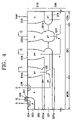
- FIG. 4 is a sectional view illustrating an exemplary structure for a power semiconductor device for suppressing a substrate recirculation current, according to an embodiment of the present invention
- FIG. 5 is an equivalent circuit diagram of a parasitic transistor in the power semiconductor device of FIG. 4 , according to an embodiment of the present invention
- FIG. 6 is a sectional view illustrating exemplary parasitic transistors and resistors in the power semiconductor device of FIG. 4 ;
- FIG. 7 is a graph illustrating exemplary current-voltage characteristics of a drain current and a current of the control unit CON to a drain voltage in the power semiconductor device of FIG. 4 ;
- FIG. 8 is a graph illustrating an exemplary current characteristic in the control unit CON depending on a distance between a power transistor unit MOS and a control unit CON in the power semiconductor device of FIG. 4 , and in comparison with a conventional case;
- FIGS. 9 to 12 are sectional views illustrating an exemplary method of fabricating a power semiconductor device, according to an embodiment of the present invention.
- FIGS. 1 through 12 of the drawings Like numerals are used for like and corresponding parts of the various drawings.
- FIG. 1 is a circuit diagram of a general transistor bridge having an inductive load.
- Transistors M 1 , M 2 , M 3 , and M 4 of FIG. 1 are power transistors, which could be, for example, DMOS (double diffused MOS) transistors. Each of these transistors M 1 , M 2 , M 3 , and M 4 has a responsive diode D 1 , D 2 , D 3 , or D 4 . Each of the diodes D 1 , D 2 , D 3 , and D 4 serves as a recovery diode.
- transistor bridges typically operate as follows: when diagonally disposed transistors M 1 and M 4 (or M 2 and M 3 ) in the transistor bridge are alternately switched on or off, currents in opposite directions are repeatedly applied to the inductive load M. During the switching operation, a parasitic transistor may be operated. The operation of the parasitic transistor generates a substrate recirculation current, which could lead to various problems.
- FIGS. 2A and 2B are sectional views illustrating two transistor structures of the transistor bridge of FIG. 1 .
- a transistor of FIG. 2A is an upper transistor M 1 or M 3
- a transistor of FIG. 2B is a lower transistor M 2 or M 4 .
- an epitaxial layer 110 is arranged on a p ⁇ type substrate 100 having a transistor unit MOS, an isolating unit ISO, and a control unit CON.
- An n + type buried layer 121 and a p + type bottom layer 131 are arranged on a junction portion of the p ⁇ type substrate 100 and the epitaxial layer 110 .
- the n + type buried layer 121 is formed in the transistor unit MOS and the control unit CON, and the p + type bottom layer 131 is formed in the isolating unit ISO.
- an n type well region 122 is arranged on the n + type buried layer 121 , and an n + type sink region 125 surrounds the n type well region 122 .
- the bottom of the n + type sink region 125 makes contact with the upper surface of the n + type buried layer 121 .
- a p type body region 123 is formed in a region on the n type well region 122 .
- An n + type source region 124 is arranged in a region on the p type body region 123 .
- a gate insulating layer 127 and a gate conductive layer 128 are sequentially arranged on a channel forming region of the p type body region 123 surrounding the n + type source region 124 .
- n + type drain region 126 is arranged on the n + type sink region 125 .
- the n + type source region 124 , the n + type drain region 126 , and the gate conductive layer 128 are connected to a source terminal S, a drain terminal D, and a gate terminal G through metal interconnection lines, respectively.
- a p + type isolation region 132 is arranged on the p + type bottom layer 131 .
- the bottom of the p + type isolation region 132 makes contact with the upper surface of the p + type bottom layer 131 .
- the p + type isolation region 132 is connected to the ground terminal.
- the n type well region 122 is arranged on the n + type buried layer 121 .
- several diffusion areas constituting control elements can be arranged in the n type well region 122 .
- the transistor bridge of FIG. 1 which consists of transistors having the aforementioned structure, it is possible for the upper transistor M 1 and the lower transistor M 4 to turn off before the upper transistor M 3 and the lower transistor M 2 turn on.
- the diode D 1 of FIG. 1 is biased in a forward direction, so that a current flows from the source terminals to the drain terminals.
- a pnp type parasitic bipolar junction transistor Q 1 turns on, so that the substrate recirculation current flows into the p ⁇ type substrate 100 .
- control unit CON is biased in a forward direction, so that a current flows from the source terminals to the drain terminals.
- an npn type parasitic bipolar junction transistor Q 2 turns on, so that a current from the control unit CON flows to the drain terminal D through the substrate 100 . Since a current from the control unit CON undesirably flows to the transistor unit MOS through the substrate 100 , control operations may be unable to function normally in the control unit CON.
- FIG. 3A is a sectional view illustrating another example of the transistor structure of FIG. 2B .
- FIG. 3B is an equivalent circuit diagram of a parasitic transistor in the transistor structure of FIG. 3A .
- the same reference numerals denote the same elements.
- the first and the second p + type bottom layers 131 a and 131 b are separated from each other in the isolating unit ISO.
- An n + type buried layer 121 is arranged between the bottom layers 131 a and 131 b .
- the first p + type isolation region 132 a is arranged on the first p + type bottom layer 131 a
- the second p + type isolation region 132 b is arranged on the second p + type bottom layer 131 b
- the n + type sink region 125 is arranged on the n + type buried layer 121 .
- the first p + type isolation region 132 a , the second p + type isolation region 132 b , and the n + type sink region 125 are connected to the ground terminal.
- the first npn type parasitic bipolar junction transistor Q 2 is almost equal to the npn type parasitic bipolar junction transistor Q 1 of FIG. 2B , except that a collector region is connected to the n + type buried layer 121 and the n type well region 122 of the control unit CON as well as the n + type buried layer 121 and the n + type sink region 125 of the isolating unit ISO.
- the second npn type parasitic bipolar junction transistor Q 21 includes: the second p + type bottom layer 131 b and the second p + type isolation region 132 b of the isolating unit ISO as a base; the n + type buried layer 121 and the n + type sink region 125 of the control unit CON as a collector; and the n + type buried layer 121 , the n + type sink region 125 , and the n + type drain region 126 of the transistor unit MOS as an emitter.
- the substrate recirculation current flowing to the transistor unit MOS through the first npn type parasitic bipolar junction transistor Q 2 comprises a current I 1 from the control unit CON and currents from the n + type buried layer 121 and n + type sink region 125 of the isolating unit ISO.
- the amount of current I 1 applied from the control unit CON decreases.
- the current I 1 applied from the control unit CON decreases, the current I 1 applied from the control unit CON still flows to the transistor unit MOS through the first npn type parasitic bipolar junction transistor Q 2 .
- the number of the isolation regions 132 a and 132 b in the isolating unit ISO and the n + type sink region 125 should be increased.
- this requires more area in order to accommodate the increased number of elements.
- the current applied from the control unit CON additionally flows to the transistor unit MOS through the second npn type parasitic bipolar junction transistor Q 21 , there is a problem in that the elements in the control unit CON may result in abnormal operations.
- FIG. 4 is a sectional view illustrating an exemplary structure for a power semiconductor device for suppressing a substrate recirculation current, according to an embodiment of the present invention
- FIG. 5 is an equivalent circuit diagram of a parasitic transistor in the exemplary structure for the power semiconductor device of FIG. 4 .
- an epitaxial layer 210 is arranged on a p ⁇ type substrate 200 having a transistor unit MOS, an isolating unit ISO, and a control unit CON.
- a DMOS (double diffused MOS) transistor is formed in the transistor unit MOS.
- Control elements are formed in the control unit CON.
- a junction isolation region for isolating the transistor unit MOS from the control unit CON is formed in the isolating unit ISO.
- An n + type buried layer 221 and a p + type bottom layer 231 a and 231 b are arranged on a junction portion of the p ⁇ type substrate 200 and the epitaxial layer 210 .
- the n + type buried layer 221 is formed over the transistor unit MOS and extends a predetermined distance to the adjacent isolating unit ISO. Further, the n + type buried layer 221 is also formed in the control unit CON.
- the first p + type bottom layer 231 a is formed over the transistor unit MOS and extends a predetermined distance to the adjacent isolating unit ISO.
- the first p + type bottom layer 231 a in the transistor unit MOS and the isolating unit ISO are arranged to cover both the top side and the bottom side of the n + type buried layer 221 .
- the second p + type bottom layer 231 b is formed in the isolating unit ISO.
- the second p + type bottom layer 231 b in the isolating unit ISO is separated by a predetermined distance from the n + type buried layer 221 extending from the transistor unit MOS to the isolating unit ISO. Further, the second p + type bottom layer 231 b in the isolating unit ISO is separated by a predetermined distance from the n + type buried layer 221 in the control unit CON.
- an n type well region 222 is arranged on the first p + type bottom layer 231 a .
- a p type body region 223 and an n + type drain region 226 are separately arranged in a region on the n type well region 222 .
- An n + type source region 224 is arranged in a region on the p type body region 223 .
- a gate insulating layer 227 and a gate conductive layer 228 are sequentially arranged on a channel forming region of the p type body region 223 surrounding the n + type source region 224 .
- the n + type source region 224 , the n + type drain region 226 , and the gate conductive layer 228 are connected to a source terminal S, a drain terminal D, and a gate terminal G through metal interconnection lines, respectively.
- the first p + type isolation region 232 a is arranged on the first p + type bottom layer 231 a .
- a bottom of the first p + type isolation region 232 a makes contacts with a top of the first p + type bottom layer 231 a .
- the first p + type isolation region 232 a is connected to a ground terminal.
- An n + type region 225 is arranged on the n + type buried layer 221 extending from the transistor unit MOS.
- a bottom of the n + type region 225 makes contacts with a top of the n + type buried layer 221 .
- the n + type region 225 is connected to the ground terminal.
- the second p + type isolation region 232 b is arranged on the second p + type bottom layer 231 b , separated by a predetermined distance from the n + type buried layer 221 . A bottom of the second p + type isolation region 232 b contacts with a top surface of the second p + type bottom layer 231 b . The second p + type isolation region 232 b is connected to the ground terminal.
- the n type well region 222 is arranged on the n + type buried layer 221 . Although not shown in the drawings, several diffusion regions constituting the control element may be arranged in the n type well region 222 .
- the n type well region 222 is connected to a bias voltage (Vdd) terminal.
- the element there are the first npn type parasitic bipolar junction transistor Q 2 and the second npn type parasitic bipolar junction transistor Q 21 .
- the base and the collector of the first npn type parasitic bipolar junction transistor Q 2 are grounded, and the emitter thereof is connected to the transistor unit MOS.
- the base and the emitter of the second npn type parasitic bipolar junction transistor Q 21 are grounded, and the collector thereof is connected to the control unit CON.
- the base of the first npn type parasitic bipolar junction transistor Q 2 is grounded through the first p + type isolation region 232 a of the isolating unit ISO.
- the collector thereof is grounded through the n + type buried layer 221 and the n + type region 225 of the isolating unit ISO.
- the emitter thereof is connected to the drain terminal D of the transistor unit MOS through the n + type buried layer 221 , the n type well region 222 , and the n + type drain region 226 .
- the n + type buried layer 221 and the n type well region 222 are electrically separated by the first p + type bottom layer 231 a in the transistor unit MOS as shown in the drawings, the n + type buried layer 221 and the n type well region 222 may actually make contact with other portions (not explicitly shown).
- the base of the first npn type parasitic bipolar junction transistor Q 21 is grounded through the p ⁇ type substrate 200 , the second p + type bottom layer 231 b and the second p + type isolation region 232 b of the isolating unit ISO.
- the collector is connected to the bias voltage (Vdd) terminal through the n + type buried layer 221 and the n type well region 222 of the control unit CON.
- the emitter is grounded through the n + type buried layer 221 and the n + type region 225 in the isolating unit ISO.
- the first npn type parasitic bipolar junction transistor Q 2 operates when a voltage applied to the drain terminal D becomes lower than that of the ground terminal. As a result, a current flows from the n + type buried layer 221 and the n + type region 225 of the isolating unit ISO to the drain terminal D through the n type well region 222 and the n + type drain region 226 of the transistor unit MOS.
- the first npn type parasitic bipolar junction transistor Q 2 does not influence a current in the control unit CON because the first npn type parasitic bipolar junction transistor Q 2 is electrically separated from the control unit CON.
- the second npn type parasitic bipolar junction transistor Q 21 serves as a diode having the n + type buried layer 221 of the control unit CON as a cathode and the p ⁇ type substrate 200 as an anode. Since the cathode of this diode is connected to the bias voltage (Vdd) terminal and the anode is connected to the ground terminal, a reverse bias is applied to the diode, so that the diode does not turn on. As a result, even if the first npn type parasitic bipolar junction transistor Q 2 is in operation, the first npn type parasitic bipolar junction transistor Q 2 does not influence the current of the control unit CON.
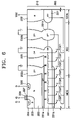
- FIG. 6 is a sectional view illustrating exemplary parasitic transistors and resistors in the power semiconductor device of FIG. 4 .
- the same reference numerals denote the same elements.
- the second npn type bipolar junction transistor Q 21 may have a structure in which several transistors are connected in series, which may be along the horizontal direction.
- a resistance R is arranged in the n + type buried layer 221 in the horizontal direction between collectors of the second npn type bipolar junction transistors Q 21 . Although ideally the resistance R can be ignored, in actuality the resistance R should not be taken into account according to the impurity density of the n + type buried layer 221 .
- a forward bias due to voltage drop caused by the resistance R may be applied to the diode formed with the second npn parasitic bipolar junction transistor Q 21 .
- the resistances should be maintained under a predetermined value. Therefore, the resistance should have an impurity density which is higher than a predetermined amount.
- the impurity density of the n + type buried layer 221 is adjusted within a range of about 1 ⁇ 10 19 /cm 3 to 9 ⁇ 10 19 /cm 3 . the impurity density may be higher when the bias voltage (Vdd) of the control unit CON becomes 5V or less.
- FIG. 7 is a graph illustrating exemplary current-voltage characteristics of a drain current and a current of the control unit CON to a drain voltage in the power semiconductor device of FIG. 4 .
- a drain current of the transistor unit MOS increases by operation of the first npn type parasitic bipolar junction transistor Q 2 as already described when a voltage of the drain terminal D becomes higher negatively.
- a current of the control unit CON may have a relatively low value of, for example, about 1 ⁇ 10 10 A (that is, 10 nA), because an operation of the first npn type parasitic bipolar junction transistor Q 2 does not influence the current of the control unit CON, and the second npn type parasitic bipolar junction transistor Q 21 does not turn on.
- FIG. 8 is a graph illustrating an exemplary current characteristic in the control unit CON depending on a distance between a power transistor unit MOS and a control unit CON in the power semiconductor device of FIG. 4 , and in comparison with a conventional case.
- the power semiconductor device of FIG. 2B has the highest value in a current of the control unit CON.
- the current value of the control unit CON decreases.
- the power semiconductor device of FIG. 3A has a smaller current value than the power semiconductor device of FIG. 2B .
- the current value of the control unit CON decreases, but the amount of decrease is small, so that it cannot have a large effect.
- the distance between the transistor unit MOS and the control unit CON increases, the current value of the control unit CON decreases.
- the current of the control unit CON is lower than the power semiconductor devices of FIGS. 2B and 3A .
- the current value of the control unit CON decreases.
- the current value of the control unit CON in the exemplary power semiconductor device according to one embodiment of the present invention (where the distance between the transistor unit MOS and the control unit CON is 100 ⁇ m or less) is much less than the current value of the control unit CON in conventional power semiconductor devices (where the distance between the transistor unit MOS and the control unit CON is 700 ⁇ m or more). Therefore, it can be understood that the exemplary power semiconductor device according to one embodiment of the present invention provides a larger effect in an integrated element.
- FIGS. 9 to 12 are sectional views illustrating an exemplary method of fabricating the power semiconductor device, according to an embodiment of the present invention.
- a transistor unit MOS, an isolating unit ISO, and a control unit CON may be sequentially disposed on a p ⁇ type substrate 200 in a horizontal direction.
- a mask layer pattern 310 for example, a photoresist layer pattern, is formed on the p ⁇ type substrate 200 .
- the photoresist layer pattern 310 covers some portions of the isolating unit ISO. Portions exposed by the photoresist layer pattern 310 are to be n + type buried layers.
- n type impurity ions may be implanted with an ion implanting process using the photoresist layer pattern 310 as an ion implanting mask.
- Arsenide (As) ions and antimony (Sb) ions which have a relatively good diffusion property, may be used as the n type impurity ions.
- the photoresist layer pattern 310 of FIG. 9 is removed.
- the implanted n type impurity ions may be diffused with a general impurity ion diffusing process.
- the n + type buried layer 221 is formed in the transistor unit MOS and the control unit CON.
- the n + type buried layer 221 extending from the transistor unit MOS is formed by a predetermined distance in the isolating unit ISO.
- a mask layer pattern 320 for example, a photoresist layer pattern, is again formed on the p ⁇ type substrate 200 .
- the photoresist layer pattern 320 the surface of the transistor unit MOS and some portions of the isolating unit ISO are exposed, and the surface of the control unit CON is covered.
- the n + type buried layer 221 is covered and the surface, where there are not n + type buried layers 221 , is exposed.
- p type impurity ions are implanted with the ion implanting process using the photoresist layer pattern 320 as an ion implanting mask. Boron (B) ions may be used as the p type impurity ions.
- the photoresist layer pattern 320 is removed.
- the p type impurity ions implanted with a general impurity ion diffusing process are diffused.
- the n type epitaxial layer 210 may then be formed with an epitaxial growing process.
- the process of diffusing the p type impurity ions may be omitted, and the p type impurity ions implanted for epitaxial growth may be diffused with a heat treatment.
- the first p + type bottom layer 231 a may be formed on a top and a bottom of the n + type buried layer 221 , and the first p + type bottom layer 231 a extends to a region of the isolating unit ISO adjacent to the transistor unit MOS.
- the second p + type bottom layer 231 b is formed by a predetermined distance from the n + type buried layer 221 .
- the DMOS transistor element is formed in the transistor unit MOS.
- the first and second p + type isolation regions 232 a and 232 b and the n + type region 225 may be formed in the isolating unit ISO.
- the first p + type isolation region 232 a can be formed to make contact with an upper portion (or top) of the first p + type bottom layer 231 a .
- the n + type region 225 is formed to contact with an upper portion of the n + type buried layer 221 .
- the second p + type isolation region 232 b is formed to make contact with a top of the second p + type bottom layer 231 b . Therefore, as shown in the drawings, in an exemplary power semiconductor device, the first npn type parasitic bipolar junction transistor Q 2 can be electrically separated from the control unit CON.
- a current from the control unit CON into a substrate by switching the power semiconductor device can be suppressed even in operations of a parasitic bipolar junction transistor by electrically separating the parasitic bipolar junction transistor from the control unit CON.
- a characteristic change or a malfunction of the control unit CON caused by operating the parasitic bipolar junction transistor can be prevented.
- a method of fabricating the exemplary power semiconductor device according to an embodiment of the present invention it is possible to obtain a power semiconductor device having the above structure using a general process without significantly increasing the number of masks.
Abstract
Description
Claims (7)
Priority Applications (1)
| Application Number | Priority Date | Filing Date | Title |
|---|---|---|---|
| US12/229,019 US7888226B2 (en) | 2004-05-08 | 2008-08-18 | Method of fabricating power semiconductor device for suppressing substrate recirculation current |
Applications Claiming Priority (2)
| Application Number | Priority Date | Filing Date | Title |
|---|---|---|---|
| KR10-2004-0032494 | 2004-05-08 | ||
| KR1020040032494A KR101042148B1 (en) | 2004-05-08 | 2004-05-08 | Power semiconductor device for surpressing substrate recirculation current and mthod for fabricating the same |
Related Child Applications (1)
| Application Number | Title | Priority Date | Filing Date |
|---|---|---|---|
| US12/229,019 Division US7888226B2 (en) | 2004-05-08 | 2008-08-18 | Method of fabricating power semiconductor device for suppressing substrate recirculation current |
Publications (2)
| Publication Number | Publication Date |
|---|---|
| US20050263800A1 US20050263800A1 (en) | 2005-12-01 |
| US7420260B2 true US7420260B2 (en) | 2008-09-02 |
Family
ID=35424216
Family Applications (2)
| Application Number | Title | Priority Date | Filing Date |
|---|---|---|---|
| US11/123,400 Active US7420260B2 (en) | 2004-05-08 | 2005-05-06 | Power semiconductor device for suppressing substrate recirculation current and method of fabricating power semiconductor device |
| US12/229,019 Expired - Fee Related US7888226B2 (en) | 2004-05-08 | 2008-08-18 | Method of fabricating power semiconductor device for suppressing substrate recirculation current |
Family Applications After (1)
| Application Number | Title | Priority Date | Filing Date |
|---|---|---|---|
| US12/229,019 Expired - Fee Related US7888226B2 (en) | 2004-05-08 | 2008-08-18 | Method of fabricating power semiconductor device for suppressing substrate recirculation current |
Country Status (2)
| Country | Link |
|---|---|
| US (2) | US7420260B2 (en) |
| KR (1) | KR101042148B1 (en) |
Cited By (5)
| Publication number | Priority date | Publication date | Assignee | Title |
|---|---|---|---|---|
| US20070132008A1 (en) * | 2005-11-22 | 2007-06-14 | Taeg-Hyun Kang | High voltage integration circuit with freewheeling diode embedded in transistor |
| US20090127660A1 (en) * | 2007-11-19 | 2009-05-21 | Wooseok Kim | Structure and method for forming a guard ring to protect a control device in a power semiconductor ic |
| US8514028B2 (en) * | 2011-08-17 | 2013-08-20 | International Business Machines Corporation | Load tolerant voltage controlled oscillator (VCO), IC and CMOS IC including the VCO |
| US10374082B2 (en) | 2016-06-29 | 2019-08-06 | Samsung Electronics Co., Ltd. | Semiconductor device |
| US11282954B2 (en) * | 2018-10-30 | 2022-03-22 | Stmicroelectronics S.R.L. | LDMOS device with integrated P-N junction diodes |
Families Citing this family (3)
| Publication number | Priority date | Publication date | Assignee | Title |
|---|---|---|---|---|
| US7902606B2 (en) * | 2008-01-11 | 2011-03-08 | International Business Machines Corporation | Double gate depletion mode MOSFET |
| US7915944B2 (en) * | 2009-04-27 | 2011-03-29 | General Electric Company | Gate drive circuitry for non-isolated gate semiconductor devices |
| RU2688866C1 (en) * | 2018-03-12 | 2019-05-22 | Федеральное государственное бюджетное образовательное учреждение высшего образования "Кабардино-Балкарский государственный университет им. Х.М. Бербекова" (КБГУ) | Semiconductor device manufacturing method |
Citations (3)
| Publication number | Priority date | Publication date | Assignee | Title |
|---|---|---|---|---|
| US5541123A (en) * | 1992-09-21 | 1996-07-30 | Siliconix Incorporated | Method for forming a bipolar transistor having selected breakdown voltage |
| US5643820A (en) * | 1992-09-21 | 1997-07-01 | Siliconix Incorporated | Method for fabricating an MOS capacitor using zener diode region |
| US5973366A (en) * | 1996-12-25 | 1999-10-26 | Fuji Electric Co., Ltd. | High voltage integrated circuit |
Family Cites Families (4)
| Publication number | Priority date | Publication date | Assignee | Title |
|---|---|---|---|---|
| US5246871A (en) * | 1989-06-16 | 1993-09-21 | Sgs-Thomson Microelectronics S.R.L. | Method of manufacturing a semiconductor device comprising a control circuit and a power stage with a vertical current flow, integrated in monolithic form on a single chip |
| US5179432A (en) * | 1991-08-15 | 1993-01-12 | Micrel, Inc. | Integrated PNP power bipolar transistor with low injection into substrate |
| KR100272176B1 (en) * | 1998-09-30 | 2000-12-01 | 김덕중 | Method fabricating bicdmos device |
| JP3308505B2 (en) * | 1999-04-19 | 2002-07-29 | セイコーインスツルメンツ株式会社 | Semiconductor device |
-
2004
- 2004-05-08 KR KR1020040032494A patent/KR101042148B1/en not_active IP Right Cessation
-
2005
- 2005-05-06 US US11/123,400 patent/US7420260B2/en active Active
-
2008
- 2008-08-18 US US12/229,019 patent/US7888226B2/en not_active Expired - Fee Related
Patent Citations (9)
| Publication number | Priority date | Publication date | Assignee | Title |
|---|---|---|---|---|
| US5541123A (en) * | 1992-09-21 | 1996-07-30 | Siliconix Incorporated | Method for forming a bipolar transistor having selected breakdown voltage |
| US5541125A (en) * | 1992-09-21 | 1996-07-30 | Siliconix Incorporated | Method for forming a lateral MOS transistor having lightly doped drain formed along with other transistors in the same substrate |
| US5547880A (en) * | 1992-09-21 | 1996-08-20 | Siliconix Incorporated | Method for forming a zener diode region and an isolation region |
| US5559044A (en) * | 1992-09-21 | 1996-09-24 | Siliconix Incorporated | BiCDMOS process technology |
| US5583061A (en) * | 1992-09-21 | 1996-12-10 | Siliconix Incorporated | PMOS transistors with different breakdown voltages formed in the same substrate |
| US5618743A (en) * | 1992-09-21 | 1997-04-08 | Siliconix Incorporated | MOS transistor having adjusted threshold voltage formed along with other transistors |
| US5643820A (en) * | 1992-09-21 | 1997-07-01 | Siliconix Incorporated | Method for fabricating an MOS capacitor using zener diode region |
| US5648281A (en) * | 1992-09-21 | 1997-07-15 | Siliconix Incorporated | Method for forming an isolation structure and a bipolar transistor on a semiconductor substrate |
| US5973366A (en) * | 1996-12-25 | 1999-10-26 | Fuji Electric Co., Ltd. | High voltage integrated circuit |
Cited By (9)
| Publication number | Priority date | Publication date | Assignee | Title |
|---|---|---|---|---|
| US20070132008A1 (en) * | 2005-11-22 | 2007-06-14 | Taeg-Hyun Kang | High voltage integration circuit with freewheeling diode embedded in transistor |
| US7732858B2 (en) * | 2005-11-22 | 2010-06-08 | Fairchild Korea Semiconductor, Ltd. | High voltage integration circuit with freewheeling diode embedded in transistor |
| US20100244756A1 (en) * | 2005-11-22 | 2010-09-30 | Taeg-Hyun Kang | High Voltage Integration Circuit With Freewheeling Diode Embedded in Transistor |
| US8049306B2 (en) | 2005-11-22 | 2011-11-01 | Fairchild Korea Semiconductor, Ltd. | High voltage integration circuit with freewheeling diode embedded in transistor |
| US20090127660A1 (en) * | 2007-11-19 | 2009-05-21 | Wooseok Kim | Structure and method for forming a guard ring to protect a control device in a power semiconductor ic |
| US8686531B2 (en) * | 2007-11-19 | 2014-04-01 | Fairchild Korea Semiconductor, Ltd. | Structure and method for forming a guard ring to protect a control device in a power semiconductor IC |
| US8514028B2 (en) * | 2011-08-17 | 2013-08-20 | International Business Machines Corporation | Load tolerant voltage controlled oscillator (VCO), IC and CMOS IC including the VCO |
| US10374082B2 (en) | 2016-06-29 | 2019-08-06 | Samsung Electronics Co., Ltd. | Semiconductor device |
| US11282954B2 (en) * | 2018-10-30 | 2022-03-22 | Stmicroelectronics S.R.L. | LDMOS device with integrated P-N junction diodes |
Also Published As
| Publication number | Publication date |
|---|---|
| US20080318401A1 (en) | 2008-12-25 |
| US20050263800A1 (en) | 2005-12-01 |
| US7888226B2 (en) | 2011-02-15 |
| KR20050107194A (en) | 2005-11-11 |
| KR101042148B1 (en) | 2011-06-16 |
Similar Documents
| Publication | Publication Date | Title |
|---|---|---|
| US7888226B2 (en) | Method of fabricating power semiconductor device for suppressing substrate recirculation current | |
| US6989568B2 (en) | Lateral high-breakdown-voltage transistor having drain contact region | |
| US7476593B2 (en) | Semiconductor device and method of forming the same | |
| US7718481B2 (en) | Semiconductor structure and method of manufacture | |
| US5418185A (en) | Method of making schottky diode with guard ring | |
| US6570229B1 (en) | Semiconductor device | |
| EP0420672B1 (en) | Semiconducteur stubstrate structure for use in power IC device | |
| JPH0347593B2 (en) | ||
| JPH08181334A (en) | Zener diode having high reverse breakdown voltage | |
| US5798560A (en) | Semiconductor integrated circuit having a spark killer diode | |
| KR100275758B1 (en) | Horizontal Morse Gate Semiconductor Device with Zener Diode and Manufacturing Method Thereof | |
| US20010040266A1 (en) | Integrated circuit with highly efficient junction insulation | |
| JPH07297373A (en) | Integrated driver circuit device for inductive load element | |
| EP0193172A2 (en) | Vertical MOS transistor with peripheral circuit | |
| US6995453B2 (en) | High voltage integrated circuit including bipolar transistor within high voltage island area | |
| US7973360B2 (en) | Depletable cathode low charge storage diode | |
| US6445057B1 (en) | Semiconductor device having a trimming circuit for suppressing leakage current | |
| US6878998B1 (en) | Semiconductor device with region that changes depth across the direction of current flow | |
| US6982473B2 (en) | Bipolar transistor | |
| US6780685B1 (en) | Semiconductor device and manufacturing method thereof | |
| JP4231658B2 (en) | Semiconductor device and manufacturing method thereof | |
| JP2988047B2 (en) | Semiconductor device | |
| JPS6359262B2 (en) | ||
| KR100591247B1 (en) | Semiconductor device and a method for manufacturing the same | |
| KR100278424B1 (en) | Thin active layer semiconductor device with high breakdown voltage |
Legal Events
| Date | Code | Title | Description |
|---|---|---|---|
| STCF | Information on status: patent grant |
Free format text: PATENTED CASE |
|
| AS | Assignment |
Owner name: FAIRCHILD KOREA SEMICONDUCTOR, LTD., KOREA, REPUBL Free format text: ASSIGNMENT OF ASSIGNORS INTEREST;ASSIGNORS:KWON, TA-HUN;KIM, CHEOL-JOONG;JEONG, YOUNG-SUB;REEL/FRAME:021430/0448;SIGNING DATES FROM 20050509 TO 20050518 |
|
| FEPP | Fee payment procedure |
Free format text: PAYOR NUMBER ASSIGNED (ORIGINAL EVENT CODE: ASPN); ENTITY STATUS OF PATENT OWNER: LARGE ENTITY |
|
| FEPP | Fee payment procedure |
Free format text: PAYOR NUMBER ASSIGNED (ORIGINAL EVENT CODE: ASPN); ENTITY STATUS OF PATENT OWNER: LARGE ENTITY Free format text: PAYER NUMBER DE-ASSIGNED (ORIGINAL EVENT CODE: RMPN); ENTITY STATUS OF PATENT OWNER: LARGE ENTITY |
|
| FPAY | Fee payment |
Year of fee payment: 4 |
|
| FPAY | Fee payment |
Year of fee payment: 8 |
|
| AS | Assignment |
Owner name: SEMICONDUCTOR COMPONENTS INDUSTRIES, LLC, ARIZONA Free format text: ASSIGNMENT OF ASSIGNORS INTEREST;ASSIGNOR:FAIRCHILD KOREA SEMICONDUCTOR, LTD.;REEL/FRAME:044361/0205 Effective date: 20171102 |
|
| AS | Assignment |
Owner name: DEUTSCHE BANK AG NEW YORK BRANCH, AS COLLATERAL AGENT, NEW YORK Free format text: PATENT SECURITY AGREEMENT;ASSIGNORS:SEMICONDUCTOR COMPONENTS INDUSTRIES, LLC;FAIRCHILD SEMICONDUCTOR CORPORATION;REEL/FRAME:046530/0460 Effective date: 20171110 Owner name: DEUTSCHE BANK AG NEW YORK BRANCH, AS COLLATERAL AG Free format text: PATENT SECURITY AGREEMENT;ASSIGNORS:SEMICONDUCTOR COMPONENTS INDUSTRIES, LLC;FAIRCHILD SEMICONDUCTOR CORPORATION;REEL/FRAME:046530/0460 Effective date: 20171110 |
|
| MAFP | Maintenance fee payment |
Free format text: PAYMENT OF MAINTENANCE FEE, 12TH YEAR, LARGE ENTITY (ORIGINAL EVENT CODE: M1553); ENTITY STATUS OF PATENT OWNER: LARGE ENTITY Year of fee payment: 12 |
|
| AS | Assignment |
Owner name: FAIRCHILD SEMICONDUCTOR CORPORATION, ARIZONA Free format text: RELEASE OF SECURITY INTEREST IN PATENTS RECORDED AT REEL 046530, FRAME 0460;ASSIGNOR:DEUTSCHE BANK AG NEW YORK BRANCH, AS COLLATERAL AGENT;REEL/FRAME:064075/0001 Effective date: 20230622 Owner name: SEMICONDUCTOR COMPONENTS INDUSTRIES, LLC, ARIZONA Free format text: RELEASE OF SECURITY INTEREST IN PATENTS RECORDED AT REEL 046530, FRAME 0460;ASSIGNOR:DEUTSCHE BANK AG NEW YORK BRANCH, AS COLLATERAL AGENT;REEL/FRAME:064075/0001 Effective date: 20230622 |