US7529589B2 - Intravascular electrophysiological system and methods - Google Patents
Intravascular electrophysiological system and methods Download PDFInfo
- Publication number
- US7529589B2 US7529589B2 US10/862,113 US86211304A US7529589B2 US 7529589 B2 US7529589 B2 US 7529589B2 US 86211304 A US86211304 A US 86211304A US 7529589 B2 US7529589 B2 US 7529589B2
- Authority
- US
- United States
- Prior art keywords
- pulse generator
- electrode
- anchor
- patient
- device body
- Prior art date
- Legal status (The legal status is an assumption and is not a legal conclusion. Google has not performed a legal analysis and makes no representation as to the accuracy of the status listed.)
- Active, expires
Links
Images


Classifications
-
- A—HUMAN NECESSITIES
- A61—MEDICAL OR VETERINARY SCIENCE; HYGIENE
- A61N—ELECTROTHERAPY; MAGNETOTHERAPY; RADIATION THERAPY; ULTRASOUND THERAPY
- A61N1/00—Electrotherapy; Circuits therefor
- A61N1/02—Details
- A61N1/04—Electrodes
- A61N1/05—Electrodes for implantation or insertion into the body, e.g. heart electrode
- A61N1/056—Transvascular endocardial electrode systems
- A61N1/057—Anchoring means; Means for fixing the head inside the heart
-
- A—HUMAN NECESSITIES
- A61—MEDICAL OR VETERINARY SCIENCE; HYGIENE
- A61N—ELECTROTHERAPY; MAGNETOTHERAPY; RADIATION THERAPY; ULTRASOUND THERAPY
- A61N1/00—Electrotherapy; Circuits therefor
- A61N1/18—Applying electric currents by contact electrodes
- A61N1/32—Applying electric currents by contact electrodes alternating or intermittent currents
- A61N1/36—Applying electric currents by contact electrodes alternating or intermittent currents for stimulation
- A61N1/372—Arrangements in connection with the implantation of stimulators
- A61N1/375—Constructional arrangements, e.g. casings
- A61N1/37512—Pacemakers
-
- A—HUMAN NECESSITIES
- A61—MEDICAL OR VETERINARY SCIENCE; HYGIENE
- A61N—ELECTROTHERAPY; MAGNETOTHERAPY; RADIATION THERAPY; ULTRASOUND THERAPY
- A61N1/00—Electrotherapy; Circuits therefor
- A61N1/18—Applying electric currents by contact electrodes
- A61N1/32—Applying electric currents by contact electrodes alternating or intermittent currents
- A61N1/36—Applying electric currents by contact electrodes alternating or intermittent currents for stimulation
- A61N1/372—Arrangements in connection with the implantation of stimulators
- A61N1/375—Constructional arrangements, e.g. casings
- A61N1/37516—Intravascular implants
-
- A—HUMAN NECESSITIES
- A61—MEDICAL OR VETERINARY SCIENCE; HYGIENE
- A61N—ELECTROTHERAPY; MAGNETOTHERAPY; RADIATION THERAPY; ULTRASOUND THERAPY
- A61N1/00—Electrotherapy; Circuits therefor
- A61N1/18—Applying electric currents by contact electrodes
- A61N1/32—Applying electric currents by contact electrodes alternating or intermittent currents
- A61N1/36—Applying electric currents by contact electrodes alternating or intermittent currents for stimulation
- A61N1/372—Arrangements in connection with the implantation of stimulators
- A61N1/375—Constructional arrangements, e.g. casings
- A61N1/37518—Anchoring of the implants, e.g. fixation
-
- A—HUMAN NECESSITIES
- A61—MEDICAL OR VETERINARY SCIENCE; HYGIENE
- A61N—ELECTROTHERAPY; MAGNETOTHERAPY; RADIATION THERAPY; ULTRASOUND THERAPY
- A61N1/00—Electrotherapy; Circuits therefor
- A61N1/18—Applying electric currents by contact electrodes
- A61N1/32—Applying electric currents by contact electrodes alternating or intermittent currents
- A61N1/36—Applying electric currents by contact electrodes alternating or intermittent currents for stimulation
- A61N1/372—Arrangements in connection with the implantation of stimulators
- A61N1/37205—Microstimulators, e.g. implantable through a cannula
Definitions
- the present invention generally relates to devices, systems, and methods for diagnosing and treating the heart.
- the invention provides methods and systems for implanting medical devices into the patient's vasculature and using the devices for sensing electrical activity and/or electrically stimulating the heart
- ICDs implanted cardioverter defibrillators
- Pacemakers are implanted in patients who have bradycardia (slow heart rate).
- the pacemakers detect periods of bradycardia and deliver electrical stimuli to increase the heartbeat to an appropriate rate.
- ICDs are implanted in patients who may suffer from episodes of fast and irregular heart rhythms called tachyarrhythmias.
- An ICD can cardiovert the heart by delivering electrical current directly to the heart to terminate an atrial or ventricular tachyarrhythmia, other than ventricular fibrillation.
- An ICD may alternatively defibrillate the heart in a patient who may suffer ventricular fibrillation (VF), a fast and irregular heart rhythm in the ventricles.
- VF ventricular fibrillation
- the heart quivers and can pump little or no blood to the body, potentially causing sudden death.
- An ICD implanted for correction of ventricular fibrillation will detect a VF episode and deliver an electrical shock to the heart to restore the heart's electrical coordination.
- AF atrial fibrillation
- atria upper chambers
- An electrophysiological device implanted for correction of atrial fibrillation will detect an AF episode and deliver an electrical shock to the atria to restore electrical coordination.
- Pacemakers and ICDs are routinely implanted in the pectoral region either under the skin (subcutaneous) or under the pectoral muscle.
- the leads are placed at appropriate locations within or on the heart.
- a cardiologist identifying a heart rhythm condition may be required to refer his or her patient to sub-specialists or surgeons for implantation of a pacemaker or ICD—thus delaying implantation of the device in a patient who urgently needs it. It is thus desirable to simplify these devices and the procedures for implanting them so as to permit their implantation by a broader range of physicians.
- the present application describes an intravascular implantable electrophysiological system that may carry out cardioversion, pacing and/or defibrillation of a human heart.
- the described system includes a pulse generator that is implantable within a blood vessel and/or the heart and electrodes coupled to the pulse generator.
- the pulse generator is introduced into a patient's vasculature, advanced to a desired vessel and anchored in place within the vessel.
- the electrode(s) are positioned within the heart or surrounding vessels as needed to deliver electrical pulses to the appropriate location.
- FIG. 1 is a perspective illustration showing human cardiac anatomy.
- FIG. 2A is a plan view generally showing components of one form of intravascular electrophysiological system which utilizes a lead on the inferior portion of the device body.
- FIG. 2B is a plan view generally showing components of a second form of intravascular electrophysiological system, which utilizes a lead on the superior portion of the device body.
- FIG. 2C is a plan view generally showing components of a third form of intravascular electrophysiological system, which has a bifurcated configuration.
- FIGS. 2D and 2E are side elevation views of distal portions of the leads of the system of FIG. 2C .
- FIG. 2F is a plan view generally showing components of a fourth form of intravascular electrophysiological system which utilizes leads on the inferior and superior portions of the device body.
- FIG. 3A is a plan view showing a first embodiment of an intravascular electrophysiological device of a type which may be used with the systems shown in FIGS. 2A-2F .
- FIG. 3B is a plan view similar to FIG. 3A showing a second embodiment of an intravascular electrophysiological device of a type which may be used with the system shown in FIGS. 2A-2F .
- FIG. 3C is a plan view showing a third embodiment of an intravascular electrophysiological device of a type which may be used with the system shown in FIGS. 2A-2F .
- FIG. 3D is a plan view similar to FIG. 3C illustrating bending of the device.
- FIG. 3E a plan view showing the mechanical features of a fourth embodiment of an intravascular electrophysiological device of a type which may be used with the system shown in FIGS. 2A-2F .
- FIG. 4A is a perspective view illustrating the coupler and rod of the embodiment of FIG. 3E .
- FIG. 4B is a perspective view illustrating the coupler and rod assembly of FIG. 4A in combination with a pair of device enclosures.
- FIGS. 5A-5E are a sequence of figures illustrating formation of the electrical and mechanical connections within a device enclosure of the type shown in FIG. 3E .
- FIG. 5A is an end view showing a device component and end cap
- FIG. 5B is a cross-sectional side view taken along the plane designated 5 B- 5 B in FIG. 5A .
- FIGS. 5C and 5D are similar to FIGS. 5A and 5B , respectively, but show the component and end cap combined with a flex circuit, enclosure and coupler.
- FIG. 5E is similar to FIG. 5D but adds the conductor assembly, rod and elastomer.
- FIGS. 6A and 6B are perspective views showing a pair of enclosures with a conductor assembly extending between them.
- FIG. 7 is a perspective end view of an enclosure showing an alternate conductor assembly extending from the enclosure for coupling to associated components in a second enclosure.
- FIG. 8A is a plan view showing a fifth embodiment of an intravascular electrophysiological device of a type that may be used with the systems shown in FIGS. 2A-2F .
- FIG. 8B is a plan view showing the ribbon portion of the fifth embodiment.
- FIG. 9A is a perspective view schematically illustrating use of an anchor to anchor an intravascular electrophysiological device within a vessel.
- FIG. 9B is cross-sectional perspective view showing a portion of the anchor of FIG. 9A .
- FIG. 9C is a perspective view similar to FIG. 9A but further illustrating use of a liner within the vessel.
- FIG. 10A is a perspective view of an anchor suitable for use with the systems of FIGS. 2A-2F .
- FIG. 10B is a perspective view showing the anchor of FIG. 10A attached to an implantable electrophysiological device and in the expanded position.
- FIG. 10C is a cross-sectional end view of the device shown in FIG. 10B .
- FIG. 10D is a side elevation view of a device showing the anchor of FIG. 10B positioned on a device and compressed by a sheath.
- FIG. 10E is similar to FIG. 10D but shows retraction of the sheath to permit expansion of the anchor within a blood vessel.
- FIGS. 11A-11F are a sequence of drawings schematically illustrating implantation of the system of FIG. 2A .
- FIGS. 12A-12E are a sequence of drawings schematically illustrating implantation of the system of FIG. 2B .
- FIGS. 13A-13C are a sequence of drawings schematically illustrating implantation of the system of FIG. 2C .
- FIGS. 13D-13I show a modification to the implantation method of FIGS. 13A-13C to include steps for implanting separately-implantable retention anchors and liners.
- FIGS. 14A-F are a sequence of drawings schematically illustrating implantation of the system of FIG. 8A .
- FIG. 15A is a plan view of a device similar to the devices of FIGS. 3A-3D and 8 A- 8 B but slightly modified to include a cuff on the lead for receiving a guidewire.
- FIG. 15B is a plan view of a device similar to the devices of FIGS. 3A-3D and 8 A- 8 B but slightly modified to include a bore in the device for receiving a guidewire.
- FIG. 15C is a plan view similar to FIG. 15B showing an alternative configuration for receiving a guidewire.
- FIG. 15D is a plan view similar to FIG. 15A showing an alternative use of the FIG. 15A device and lead.
- FIG. 15E is a cross-section view of the lead of FIG. 15D taken along the plane designated 15 E- 15 E in FIG. 15D .
- FIGS. 16A-20 schematically illustrate various applications of intravascular electrophysiological systems.
- FIG. 1 shows the cardiac anatomy of a human, including the heart and major vessels. The following anatomic locations are shown and identified by the listed reference numerals:
- the present disclosure describes intravascular electrophysiological systems that may be used for a variety of functions. These functions include defibrillation, pacing, and/or cardioversion.
- the elements of the systems described below include at least one device body and typically, but optionally, at least one lead coupled to the body.
- One or more retention devices may facilitate retention of the device body and/or leads or other elements within the vasculature.
- components such as mandrels, stylets and/or guidewires used to facilitate implantation of the system.
- FIGS. 2A through 2F illustrate systems well suited for use as defibrillators used in the treatment of tachyarrhythmias. Although the description of these systems focuses on their use in the treatment of ventricular tachycardia, systems such as these, or modifications thereof, may be used for various other electophysiologic applications, some of which are described in connection with FIGS. 16A through 19 .
- FIG. 2A One configuration of an electrophysiological system 10 a is shown in FIG. 2A .
- the elements of the FIG. 2A system 10 a include an elongate device body 12 a , lead 14 a , retention device 16 a , a sleeve 17 , a positioning mandrel 18 and an introducer sheath 19 . It should be understood that certain of these elements may be eliminated, or others added to the system, without departing from the spirit of the invention.
- Device 12 a houses components known in the art to be necessary to carry out the system functions.
- device 12 a may include one or more pulse generators, including associated batteries, capacitors, microprocessors, and circuitry for generating electrophysiological pulses for defibrillation, cardioversion and/or pacing.
- Device also includes detection circuitry for detecting arrhythmias or other abnormal activity of the heart. The specific components to be provided in the device will depend upon the application for the device, and specifically whether the device is intended to perform defibrillation, cardioversion and/or pacing along with its sensing functions.
- the device 12 a is proportioned to be passed into the vasculature and to be anchored within the patient's vasculature with minimal obstruction to blood flow.
- Suitable sites for the device 12 a may include, but are not limited to the venous system using access through the right or left femoral vein or the subclavian or brachiocephalic veins, or the arterial system using access through one of the femoral arteries.
- the housing of device 12 a preferably has a streamlined maximum cross sectional diameter which may be in the range of 3-15 mm or less, with a most preferred maximum cross-sectional diameter of 3-8 mm or less.
- the cross-sectional area of the device in the transverse direction i.e.
- This area is preferably in the range of approximately 79 mm 2 or less, and more preferably in the range of approximately 40 mm 2 or less, or most preferably between 12.5-40 mm 2 .
- the cross-section of the device may have a circular cross-section, although other cross-sections including crescent, flattened, or elliptical cross-sections may also be used. It is highly desirable to provide the device with a smooth continuous contour so as to avoid voids or recesses that could encourage thrombus formation on the device.
- a first array of electrodes 22 a is positioned on a superior region of the device body 22 a
- a second array of electrodes 24 a is positioned on an inferior region.
- Individual electrodes may be used in place of the arrays.
- Electrodes 22 a , 24 a are preferably positioned on the surface of the device 12 a .
- electrodes 22 a , 24 a may take the form of conductive elements attached to the non-conductive housing of the device 12 a .
- the electrodes may be formed by selectively applying the coating or removing portions of the coating to leave one or more exposed electrode regions on the surface of the device 12 a .
- the retention device 16 a in this and the other embodiments may include conductive elements and function as an electrode.
- a proximal portion of the device includes a connector 25 for receiving the distal end of positioning mandrel 18 , which may be used to steer the device 12 a (by pushing, pulling and/or torquing) through the patient's vasculature as described below.
- the connector 25 may take the form of a threaded bore for receiving a threaded screw member at the distal end of the mandrel 18 , or it may have any other type of configuration for detachably engaging the distal end of the mandrel.
- Mandrel 18 may serve purely mechanical purposes, or it may also be a “smart mandrel” that provides electrical and/or fluid connections. Such connections can be used to couple the device (via an instrument cable) for electrical, electronic, and/or fluid communication between the device and instrumentation located outside the body. This communication may be used several purposes, including device testing, initiation and/or programming during implantation, and/or recharging of the device battery. If the device is to be used for drug delivery, the mandrel may be used for re-filling a reservoir in the device with pharmaceutical agents that may be deliverable by the device to a patient.
- Lead 14 a is attachable to the inferior end of device 12 a as will be described in detail in the “Implantation” section, although the lead 14 a may be instead integrally connected to device.
- Lead 14 a includes one or more defibrillation and/or pacing electrodes 26 a and may also be equipped to sense electrical activity of the heart. Monitoring of the heart's electrical activity is needed to detect the onset of an arrhythmia. Activity sensed by the sensing electrode(s) is used by the device electronics to trigger delivery of a defibrillation shock. Additional leads may be provided if desired.
- the lead 14 a may be a conventional defibrillation/pacing lead, although alternative lead configurations may be desirable if warranted by the desired placement of the device 12 a and lead within the body.
- the physician will preferably want to select a location for the device within a chosen vessel (e.g. the inferior or superior vena cava) that will prevent the device from blocking significant peripheral vessels extending from that vessel.
- An optimal lead will preferably give the physician implanting the device flexibility to position the device at an appropriate location in the chosen vessel without concern that the leads extending from the device will not reach their intended location.
- the lead may include a coiled section (see coiled section 166 of FIG.
- a coiled section can allow elongation of the effective length of the lead when tension is applied to the coil.
- the coiled section or any alternate type of yieldable lead section may be a plastically deformable metal or polymer that will retain its extended configuration after it has been stretched to that configuration Other configurations that will allow additional lead length to pay out from the device if needed may also be used.
- the leads may be the helical screw-in or tined variety for fixation to the cardiac tissue, and/or they may have steroid-eluding tips to facilitate tissue in-growth for fixation purposes.
- a detachable screw-in lead tip 9 may be detachable from the lead 14 a . This allows the lead tip 9 to be left within the chamber of the heart when the remainder of the lead 14 a , so as to prevent damage to the heart tissue as could occur upon extraction of the helical tip.
- Tip 9 preferably includes a torque socket 11 a which mates with a corresponding wire torque element 11 b on the lead body 14 a to optimize torque transmission when the lead tip 9 is screwed into the heart tissue.
- the leads may include non-thrombogenic and/or non-proliferative surfaces or coatings as also described above in connection with the Device Configuration section below.
- the leads may include a coating that is anti-thrombogenic (e.g. perfluorocarbon coatings applied using supercritical carbon dioxide) so as to prevent thrombus formation on the lead. It is also beneficial for the coating to have anti-proliferative properties so as to minimize endothelialization or cellular ingrowth, since minimizing growth into or onto the lead will help minimize vascular trauma when the device is explanted.
- the coating may thus also be one which elutes anti-thrombogenic compositions (e.g. heparin sulfate) and/or compositions that inhibit cellular in-growth and/or immunosuppressive agents.
- the lead may be attachable to the device 12 a in situ or prior to implantation, or it may be permanently attached to the device, or it may be integral with the device as an elongate extension of the device itself.
- the term “lead” is used to mean an element that includes conductors and electrodes and that thus may be positioned somewhat remotely from the circuitry that energizes the electrodes.
- leads may include elements that are simply extensions or tapers of the device 12 a itself (such as the portion of the device 12 a at which electrodes 22 a are located) as well as more conventional leads.
- FIG. 2B A second embodiment of a system 10 b is shown in FIG. 2B and differs from the FIG. 2A embodiment primarily in that its lead 14 b is attachable (or integrally attached) to the superior end of device 12 b.
- the third embodiment of FIG. 2C includes two leads 14 c , 15 c , both extending from the superior end of the device 12 c .
- Either or both of the leads may be attachable or detachable from the device 12 c , permanently attached to the device, or integral with the device as an elongate extension of the device itself.
- Lead 15 c preferably includes one or more defibrillation electrodes 22 c and lead 14 c preferably includes at least one defibrillation electrode (not shown).
- Either or both of the leads may also be equipped to sense electrical activity of the heart so as to identify onset of an arrhythmia.
- the leads 14 c , 15 c will be positioned side-by-side within a blood vessel at some point, at least during implantation of the system.
- the diameters of the leads are proportioned to permit continued blood flow through the vessel even when the leads are side-by-side.
- lead 15 c is longer than lead 14 c , and includes a narrow section 28 along the portion of the lead 15 c that is adjacent to lead 14 c .
- the combined diameters of narrow section 28 and lead 14 c must be small enough to fit through the vessels through which they will be passed, and preferably do not exceed the maximum diameter of device 12 c .
- lead 15 c includes a diameter of 1-10.0 mm except at narrow section 28 which has a diameter of 0.5-9.5 mm; lead 14 c has a diameter of 1-10 mm; and device 12 c has a diameter of 3-15 mm. It should also be noted that a breakaway retention means 30 might be provided for coupling the narrow section 28 of lead 15 c with the lead 14 c during advancement of the device 12 c through the vasculature.
- the leads may include non-thrombogenic, non-proliferative and/or anti-inflammatory surfaces or coatings as also described above in connection with the device 12 a.
- Each lead 14 c , 15 c includes a guidewire lumen to aid in implantation of the lead.
- lead 15 c includes guidewire lumen 32 which extends between opening 34 and opening 36 .
- a guidewire lumen 38 in lead 14 c extends between openings 40 and 42 .
- the leads may be provided with alternative ways of receiving guidewires, many of which are known in the art and/or described below.
- the system may include guidewires 43 a , 43 b for use in implanting the leads 14 c , 15 c.
- FIG. 2F shows a fourth embodiment of a system 10 d , which also includes a pair of leads 14 d , 15 d but which differs from the system 10 c of FIG. 2C in that the leads extend from opposite ends of the device 12 d .
- the leads may be attachable/detachable to/from the device 12 d , permanently attached to the device, or integral with the device as an elongate extension of the device itself.
- the retention device 16 d differs from the retention devices 16 of the systems of FIGS. 2A , 2 B and 2 C in that it is provided as a separate component rather than being integral with the device 12 d .
- an additional retention device 16 e is provided for anchoring the lead 15 d . Details concerning the retention devices are set forth below in the section entitled “Retention Devices” describing FIGS. 9A-10E .
- FIGS. 3A , 3 B, 3 C, 3 E, and 8 A Examples of devices having space efficient arrangements of their contents are shown in FIGS. 3A , 3 B, 3 C, 3 E, and 8 A. The features of these devices are applicable to any of the systems described herein.
- a first example is identified by reference numeral 12 e in FIG. 3A .
- Device 12 e includes an elongate enclosure 20 shown in cross-section in FIG. 3A to allow the components housed within it to be seen.
- Enclosure 20 is a rigid, semi-rigid or flexible housing preferably formed of a material that is biocompatible, capable of sterilization and capable of hermetically sealing the components contained within the enclosure 20 .
- the housing may be formed of a molded compound. Alternatively, a conductive material such as titanium, stainless steel, or other materials may be used.
- the housing is preferably covered by a layer or coating 21 , which may be electrically insulative particularly if the enclosure 20 is conductive.
- a layer or coating 21 which may be electrically insulative particularly if the enclosure 20 is conductive.
- a coating is ePTFE.
- anti-thrombogenic e.g. perfluorocarbon coatings applied using supercritical carbon dioxide
- the coating may have anti-proliferative properties so as to minimize endothelialization or cellular ingrowth, since minimizing growth into or onto the device will help minimize vascular trauma when the device is explanted.
- the coating may thus also be one which elutes anti-thrombogenic compositions (e.g.
- this layer or coating may be selectively applied or removed to leave an exposed electrode region 60 on the surface of the enclosure 20 .
- FIG. 3A illustrates one means for detachably connecting a lead 14 e to the device 12 e .
- device 12 e includes a header 44 having a socket 46 .
- a pin 48 at the proximal end of lead 14 e is inserted into socket 46 .
- a series of o-ring seals 50 surround the pin 48 within the socket 46 to prevent body fluids from passing into the device 12 e .
- a set screw 52 tightens against the pin 48 to secure the pin within the socket.
- components 54 a , 54 b that govern operation of the device 12 e .
- components 54 a are associated with delivery of a defibrillation pulse via lead 14
- components 54 b are associated with the sensing function performed using sensing electrodes on the defibrillation lead or on a separate lead (not shown). Isolating components 54 a from components 54 b may be desirable if noise generated by the high voltage defibrillation circuitry 54 a during charging might interfere with performance of the sensing circuitry 54 b.
- Device 12 e further includes one or more batteries 56 for supplying power to the device, and one or more capacitors 58 for storing an electrical charge and for delivering stored charge to the defibrillation lead(s) 14 e and/or exposed electrode 60 on the enclosure 20 .
- a circuit interconnect 62 provides the electrical coupling between the electronic components 36 a , 36 b , lead 14 e , electrode 60 , batteries 56 and capacitors 58 .
- Contacts 64 couple these components to the interconnect 62 .
- the components of device 12 e may be arranged in series with one another to give the device 12 e a streamlined profile. Because the device 12 e is intended for implantation within the patient's vasculature, some flexibility maybe desired so as to allow the elongate device to be easily passed through the vasculature. Flexibility may be added by segmenting the device, such as by forming one or more breaks 66 in the enclosure 20 , and by forming one or more articulations 68 at each break 23 by connecting the segments using silicone rubber filler. The articulations 68 thus form living hinges, which bend in response to passage of the device 12 e though curved regions of the vasculature. It should be noted that in this embodiment it is desirable to form interconnect 62 as a flex circuit so that it will not prevent bending at the articulations.
- the proximal portion of the device 12 e may include a connector 25 for receiving the distal end of positioning mandrel 18 ( FIG. 2A ), which may optionally be used to push the device 12 e through the patient's vasculature as described below.
- the connector 25 may take the form of a threaded bore for receiving a threaded screw member at the distal end of the mandrel 18 , or it may have any other type of configuration for detachably engaging the distal end of the mandrel.
- FIG. 3B A second example of an arrangement of components for the intravascular electrophysiological device is shown in the device identified by reference numeral 12 f in FIG. 3B . Many of the components are the same as those shown in the FIG. 3A embodiment and will not be discussed again in connection with FIG. 3B .
- This second embodiment differs from the first embodiment primarily in that the electronic components 54 are included within a single area of the enclosure 20 .
- This configuration may be used, for example, when the device is intended only for performing pacing functions (and thus lacks the relatively noisy charging circuitry found in the defibrillation circuitry), or if isolation of the type shown in the FIG. 3A embodiment is not necessary to prevent noise from the charging circuit from interfering with the sensing circuits.
- FIGS. 3A and 3B embodiments are the device 12 g shown in FIGS. 3C and 3D .
- each segment may be separately enclosed by its own enclosure 20 a , 20 b , 20 c or partial enclosure formed of titanium or other suitable material.
- the components within the enclosures 20 a , 20 b , and 20 c are electrically connected by flex circuits 62 a , and the enclosures are connected using a flexible material such as silicone rubber filler to form articulations 68 a .
- FIG. 3D illustrates bending of the device 12 g at one of the articulations. Many of these enclosures may be “strung together” to form the device body.
- This configuration is particularly desirable for embodiments incorporating particularly long device bodies, such as the devices of the FIGS. 2A and 2B embodiments.
- device bodies such as the devices of the FIGS. 2A and 2B embodiments.
- flexibility of the device may be essential for movement and positioning of the device within the vasculature with minimal damage to the blood vessels.
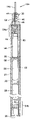
- FIG. 3E illustrates an alternative mechanical assembly of individual segments to form a device 12 h .
- the mechanical components used to connect the segments are optimally designed such that axial, flexural and torsional forces imparted to the device 12 h are transmitted by the mechanical components rather than by the electrical conductors that extend between the segments and the associated pins and feed-through components that collectively provide electrical coupling between the components in the device's segments.
- the drawing shows the device 12 h in partially-constructed form and without the electrical and electronic components, so that the mechanical elements can more easily be seen.
- Each segment comprises a tubular enclosure 20 h , which may take the form of a hollow tube having open ends 70 as shown.
- Enclosures 20 h may vary between 2 mm and 13 cm in length, depending on the nature of the elements to be housed within the enclosures.
- a device 12 h may range in length from 10-60 cm, and in most instances between 25-55 cm.
- Couplers 72 are secured (e.g. by welding or similar techniques) within the enclosures 20 h , near the ends 70 .
- Hinge regions 80 lie between the enclosures 20 h and are filled with elastomer to seal the enclosures against body fluids.
- FIG. 4A shows the couplers 72 separate from the tubular enclosures.
- Each coupler 72 includes a central bridge 74 and may include radial spokes 76 or an alternative structure that leaves open spaces for passage of conductors around the coupler as described in greater detail with respect to FIG. 5E .
- One or more stiffening rods 78 are joined to the coupler 72 .
- Each such rod 78 extends between two couplers 72 as shown in FIG. 4A to form a mechanical assembly that mechanically links a pair of adjacent enclosures 20 h as shown in FIGS. 3E and 4B .
- rod 78 is coupled to the central bridge 74 of the coupler 72 and is secured in place using welding techniques or alternative methods.
- the rod and coupler materials may be selected from materials that will transmit axial, flexural and torsional forces imparted to the device 12 h , but that will allow flexion of the device at hinge regions 80 .
- the rod 78 may thus be formed of a solid core wire, tubing, coil, or mesh braid of materials such as titanium, nitinol, stainless steel, or polymers such as nylon or polyurethane.
- Exemplary materials for the coupler 72 include titanium, nitinol, stainless steel, polymers, and Kevlar. Forming all or a portion coupler 72 of a flexible material or a spring-like material may also provide the needed flexibility.
- the coupler 72 may be fairly rigid and the rod 78 may be somewhat flexible.
- both the coupler 72 and the rod 78 may have some flexibility. It should be mentioned at this point that the coupler/rod assembly are but one example of assemblies that may be used for mechanically linking the enclosures 20 h.
- FIGS. 5A through 5E illustrate one example of a sequence of steps that may be used for assembling components into the segments 20 h and for electrically coupling components between segments 20 h of FIG. 3E .
- FIG. 5B shows a component 82 that is to be housed within a segment 20 h ( FIG. 3E ) of the device 12 h .
- Components 82 will include batteries, capacitors, circuitry, electronics, etc. The components may have the cylindrical shape as shown, or any other shape that can be inserted into the enclosure 20 h .
- Component 82 is fitted with a cap 84 formed of ceramic or other insulative material. Cap 84 may include ring 86 that seats against the component 82 as shown.
- a connector pin 88 extends through a bore hole in the cap 84 and is electrically coupled to the component 82 .
- One or more conductive pins 90 are isolated within blind holes in the cap 84 .
- Cap 84 and pins 88 , 90 may be integral with the component 82 , or they may be a separate component that is positioned in contact with the component 82 such that pin 88 is in registration with a corresponding contact on the component.
- the connector pin 88 may be angular as shown such that its free end is within the circumferential arrangement of the other pins 90 as best shown in FIG. 5A .
- the component 82 /cap 84 assembly of FIG. 5B is positioned within the segment enclosure 20 h , with a flex circuit 92 wrapped at least partially around the component 82 as shown.
- Other conductive elements may be used in place of the flex circuit, including an array of conductors embedded in polymer and molded into a sheet or extruded into a tube.
- Flex circuit 92 includes conductor tabs 94 folded over into contact with the pins 88 , 90 as shown. After the tabs 94 are positioned in contact with the pins 88 , 90 , coupler 72 (also shown separately in FIG. 4A ) is introduced into the enclosure 20 h and is secured in place using, for example, welding or a mechanical interlock. Although the rod 78 (also shown separately in FIG. 4A ) is not shown in FIGS. 5C and 5D , the rod 78 may be integral with coupler or it may be pre-connected (by welding or mechanical connection) to the coupler before or after the coupler 72 is placed in the enclosure 20 h . FIG. 5E shows the assembly with the rod 78 in place. Referring again to FIG. 4B , the rod 78 extends between adjacent segment enclosures 20 h , each of which is assembled as described above.
- a conductor assembly 98 completes the electrical connection between the segments 20 h .
- the conductor assembly may comprise wires 100 arranged in a configuration (such as the illustrated helical configuration) that will prevent damage to or disconnection of the conductors when the device flexes at the hinge regions 80 .
- the conductor assembly may be comprised of wires 102 extending through a flexible insulated ribbon 104 positioned around the rod 78 as shown in FIG. 7 .
- flexibility may be added to the conductor assembly by incorporating loops, coils, or sinusoidal bends into the wires to allow slight elongation of the net length of the wires when the device 12 h is flexed.
- the ends of the wires 100 are coupled to corresponding ones of the pins 88 , 90 .
- This connection may be made by various methods, including soldering or employment of a mechanical jack-type connector (not shown) with corresponding mating components on the wires 100 and conductors 88 , 90 .
- a mechanical jack-type connector (not shown) with corresponding mating components on the wires 100 and conductors 88 , 90 .
- the barrier 106 prevents body fluids from entering the enclosures 20 h .
- Application of the barrier 106 may be preceded by application of a paralene pre-coating or other redundant barrier to the conductors and other components within and extending between the enclosures 20 h.
- the elastomeric barrier material preferably fills the ends of the enclosures 20 h as well as the space between the enclosures. As shown in FIG. 5E , the ends 108 of the enclosure 20 h may be swaged into the elastomeric barrier 106 to facilitate retention of the barrier 106 , to improve sealing, and to minimize the chance for delamination of the elastomeric material. It may also be desirable to roughen the interior surface of the enclosure 20 h , or to form holes around the end circumference of the enclosure 20 h to create a mechanical or interference fit between the enclosure and the elastomer.
- FIG. 8A differs from the prior embodiments largely in the configuration of the capacitor 58 a , which takes the form of a coiled ribbon 112 mechanically coupled to the proximal end of the device 12 i (or to a more distal location) and electrically coupled to the circuit interconnect 62 .
- the coiled ribbon may take the form of a flex circuit of the type described in connection with FIG. 8B below, or it may be formed of layers of capacitor material overlaying one another to form the ribbon itself.
- the ribbon 112 Prior to implantation, the ribbon 112 is compressible to a streamlined condition for introduction into the body. For example, it may be placed within a delivery sheath or it may be retained in a streamlined position by winding the ribbon against the mandrel and retaining it with a shorter sleeve, suture or wire etc. As yet another example, proximal tension may be imparted on the ribbon by pulling the ribbon in the longitudinal direction, thereby elongating the ribbon while reducing its overall width, much like pulling on a coiled telephone wire. Once positioned within the vessel at the appropriate site for implantation, the capacitor is released from the compressed position and springs to an expanded position within the vessel, as further discussed in the section entitled “System Implantation” below.
- the ribbon is described as being a capacitor, it should be appreciated that a different subset of the device components may be provided in the form of a ribbon-like structure or circuit.
- the capacitor may be similar to the capacitors 58 shown in FIGS. 3A and 3B , and the device's battery may instead be formed in the coiled ribbon configuration.
- the coiled ribbon may instead be an antenna for transmitting signals alerting a physician to the occurrence of an arrhythmia, and both the capacitor and battery may take the forms shown in FIGS. 3A and 3B , or some alternate form.
- FIG. 8B is an enlarged view of the ribbon 112 used for capacitor 58 a of FIG. 8A .
- the ribbon 112 is a coiled flex circuit electrically connected to the rest of the device 12 i by tab 114 .
- Discrete capacitor segments 116 are preferably arranged in a stepped pattern on the ribbon surface and may be applied using spray-on/lithographic techniques or other means. Segments 116 have terminals 118 that may be connected in parallel using parallel connections 120 , or in series using series connections 122 as needed.
- the segments 116 may be on the exterior surface of the ribbon 112 , and/or there may be additional segments or related components 124 (including integrated circuit components, passive circuitry components, microprocessor components etc.) on the interior surface of the coil.
- the entire device may take the form of a coiled ribbon flex circuit, with the components being located on the exterior or interior surface of the ribbon and with the leads coupled to the ribbon.
- any one of the devices described herein is preferably able to communicate via wireless telemetry to an instrument outside of the patient's body. This is commonly referred to as device interrogation and/or programming and allows the physician to monitor the state and performance of the device. It also allows the physician to reconfigure the device in the case of programmable settings.
- the circuitry used for device interrogation and/or programming can be included in any of the device embodiments, with the device telemetry antenna either encapsulated within the device enclosure(s) or as part of a ribbon component set of the type shown in FIG. 8A .
- the circuitry may include a circuit that will respond in the presence of a magnetic field, which is a feature also known in the implantable device industry.
- These types of communication means are intended to allow the device to communicate the device's status to the physician.
- the status information may include the state of the battery system, and whether or not a therapeutic energy delivery had occurred or not.
- the communication might also identify the parameters the device used, including a stored electrogram, to allow reconstruction of the delivery episode by the instrument.
- the telemetry feature may also be used to program certain features governing function of the device, such as the threshold heart rate in beats per minute which, when detected by the device, will cause the device to provide appropriate energy therapy.
- the intravascular system further includes a mechanism for retaining the device in the patient's vasculature, such as in the superior vena cava 3 a , inferior vena cava 3 b , or the left or right subclavian 2 a , 2 b (see FIG. 1 ).
- a retention device is the tubular retention sleeve or anchor 16 d of the type illustrated with device 12 d in FIG. 2F and as shown in greater detail in FIGS. 9A and 9B .
- the retention device is described as a separate component from the device 12 d , but it will be appreciated that the anchor 16 d or other retention device may be integral with the device 12 d.
- the anchor 16 d may include features that give some structural stability to cause the anchor to radially support the device against a vessel wall.
- a mesh, band or other framework 126 FIG. 9B
- shape memory e.g. nickel titanium alloy, nitinol or shape memory polymer
- stainless steel Eligoy, or MP35N wires or structures
- the anchor 16 d is preferably provided with a smooth polymeric barrier 128 that is both anti-proliferative and anti-thrombogenic and that thereby prevents endothelial growth and thrombus formation on the anchor.
- Examples of materials for the polymeric barrier include, but are not limited to ePTFE, or other fluoropolymers, silicone, non-woven nylon, or biomimetic materials.
- Layers of barrier material on the interior and exterior surfaces of the framework preferably form the polymeric barrier 128 , although it will be appreciated that the framework 126 and barrier 128 may be combined in a variety of ways to prevent thrombus formation and endothelialization on the anchor walls.
- the anchor material could include surfaces for eluting non-coagulative, anti-platlet (e.g. IIBIIIA glycoprotein receptor blockers), anti-proliferative, and/or anti-inflammatory substances.
- the framework 126 may extend through the entire length of the anchor, or it may be included in only a portion of the anchor, such as at the proximal and distal end regions as shown in FIG. 9A , leaving the intermediate region 130 between them with no structural reinforcement. This arrangement may be preferable in that is allows the intermediate region to conform to the surface of the device 12 d during use. As another alternative, the intermediate region may include some structural reinforcement, but less than is provided in the more rigid proximal and distal regions 126 so as to allow some conformability of the anchor to the device surface.
- the anchor 16 d is compressed to a streamlined positioned for passage through the vasculature.
- the anchor 16 d may be inserted into a positioning sheath to facilitate movement through the vasculature.
- the anchor will be deployed after the device has been positioned at a desired location within the vessel, although if the anchor and device are integral components they will be implanted simultaneously.
- the anchor is advanced to a position adjacent the device, released from the sheath (if used) and expanded to a radially expanded position as shown in FIG. 9A .
- the anchor may self-expand and/or it may be expanded using an inflation tool such as a balloon passed into the anchor's central lumen and subsequently inflated.
- an inflation tool such as a balloon passed into the anchor's central lumen and subsequently inflated.
- the anchor When the anchor is expanded, its radial force engages the device 12 d and secure the device 12 d against the vessel wall. As shown, the force of the anchor against the device may cause the vessel to distend outwardly due to the vessel's compliance. Blood flowing through the vessel passes through the tubular interior of the anchor as indicated by arrows in FIG. 9A . Because the device 12 d occupies the distension in the vessel,
- the rims 132 a , 132 b surrounding the anchor's proximal and distal openings are preferably designed to make sealing contact against the surrounding vessel tissue (and against the lead 15 d ) as shown in FIG. 9A so as to direct all blood flow into the interior of the anchor.
- rims 132 a , 132 b may be formed of a thicker and more pliable material such as silicone or polyurethane-siloxane, or the rims may be supplemented with compliant members that seal against the lead and surrounding tissue.
- a swellable hydrogel which expands when placed in contact with fluids including blood, may be included on the anchor's ends to optimize sealing.
- these barriers will form a seal with the adjacent tissue, however it is sufficient that the barriers prevent a substantial amount of blood from passing between the exterior of the anchor and the device, without necessarily forming an impermeable seal.
- anchor 16 e FIG. 2F
- anchor 16 e FIG. 2F
- anchor 16 e FIG. 2F
- a tubular liner 134 may be deployed within the vessel prior to implantation of the device 12 d and anchor 16 d .
- Liner 134 may be similar in design to the anchor 16 d , but is preferably longer than either the device 12 d or anchor 16 d so that the liner contacts the vessel wall but the device and anchor 16 d do not. If used with the FIG.
- the liner 134 is preferably longer than the combined length of the device enclosure and coil 112 .
- the liner 134 helps to reduce the risk of trauma to the vessel tissue during explantation of the device and/or anchor 16 d.
- the liner 134 is deployed in the desired anatomic location before the device is moved into place.
- the steps for deploying the liner 134 may be similar to those described above for deploying the anchor 16 d .
- the device is deployed, followed by the anchor 16 d , in the same manner as described elsewhere.
- the liner may become endothelialized, particularly at its edges.
- the endothelial growth is self-limiting to the edge or rim of the liner due to increasing distance from a sustaining blood supply and should not reach the inner retaining anchor 16 d .
- the inner anchor 16 d may be grabbed by a surgical instrument with the outer liner 134 acting as a protective layer for the vessel.
- the liner 134 may be left in place following removal of the anchor 16 d and device 12 d . If the device 12 d (or a replacement) is to be later re-implanted, it may be returned to its original location within the liner 134 .
- the device 12 d may be “sandwiched” between the liner 134 and anchor 16 d before implantation by placing the device inside the liner, then placing the anchor in a compressed position within the liner, and then expanding the anchor to engage the device between the sleeve and anchor. The three components are then compressed into a positioning sheath and introduced as described elsewhere.
- FIGS. 10A though 10 E illustrate an alternative anchor 16 a of the type shown with the systems of FIGS. 2A through 2C .
- the anchor 16 a is beneficial in that it is implanted integrally with the device, and thus does not require a separate implantation step.
- anchor 16 a includes structural features that allow the anchor to radially engage a vessel wall.
- a band, mesh or other framework formed of one or more shape memory (e.g. nickel titanium alloy, nitinol, thermally activated shape-memory material, or shape memory polymer) elements or stainless steel, Elgiloy, or MP35N elements may be used.
- the anchor may include anti-proliferative and anti-thrombogenic coatings, although in this embodiment he anchor structure 16 a is preferably provided to promote tissue ingrowth to as to enhance anchor stability within the vessel.
- the anchor may also have drug delivery capability via a coating matrix impregnated with one or more pharmaceutical agents.
- FIG. 10B shows one anchor 16 a attached to a device 12 a , although naturally one, two or more such anchors may alternatively be used.
- anchor 16 a is attached to the implant 12 a by a collar 136 , or other suitable connection.
- the implant 12 d may include a recessed portion 138 that allows the exterior of the anchor to sit flush with the exterior of the implant 12 a when the anchor is its compressed position.
- the recessed portion should have smooth contours in order to discourage thrombus formation on the device.
- the anchor 16 a and device 12 a may be detachably connected to the recessed portion using methods that allow the anchor 16 a and the implant 12 a to be separated in situ, for permanent or temporary removal of the implant 12 a .
- a detachable connection between the anchor 16 a and implant 12 a may utilize a snap fit between the collar 136 and implant 12 a .
- both the collar 16 a and the recessed portion 138 of the implant may include an elliptical cross-section.
- the medical implant may be torqued about its longitudinal axis, causing the body of the implant to cam the edges of the collar 136 to a slightly opened position, thereby allowing the implant to be passed between the edges 140 of the collar 136 .
- a clevis pin-type connection may be made between the anchor 16 a and the device 12 a . Such a connection would be provided with a remotely actuated mechanism for releasing the clevis pin connection to thus permit separation of the device and the anchor.
- the anchor may be configured such that the device 12 a and anchor 16 a share a longitudinal axis, or such that the axes of device 12 a and anchor 16 a are longitudinally offset.
- a retractable sheath 142 may be slidably positioned over the anchor 16 a and implant 12 a so as to retain the anchor in its compressed position. Retraction of the sheath as indicated in FIG. 10E allows the anchor 16 a to expand into contact with the surrounding walls of the vessel, thereby holding the medical implant in the desired location. Once deployed, the anchor 16 a is preferably intimate to the vessel wall, which is distended slightly, allowing the vessel lumen to remain approximately continuous despite the presence of the anchor and thus minimizing turbulence or flow obstruction.
- FIGS. 11A through 15E Several methods for implanting intravascular electrophysiological systems are shown in FIGS. 11A through 15E . These implantation methods are preferably carried out under fluoroscopic visualization. Although the methods described in connection with FIGS. 11A through 15E introduce the device into the venous system via the femoral vein, the device and components may alternatively be introduced into the venous system via that subclavian vein or the brachiocephalic veins, or into the arterial system using access through one of the femoral arteries. Moreover, different components of the intravascular systems may be introduced through different access sites. For example, a device may be separately introduced through the femoral vein and a corresponding lead may be introduced via the subclavian vein.
- FIGS. 11A through 11F illustrate a method for implanting the system 10 a of FIG. 2A .
- a small incision is formed in the femoral vein and the introducer 19 is inserted through the incision into the vein to keep the incision open during the procedure.
- the device 12 a is passed into the introducer 19 , and pushed in a superior direction through the inferior vena cava 3 b (“IVC”), through the right atrium 4 a towards the superior vena cava 3 a (“SVC”).
- IVC inferior vena cava 3 b
- SVC superior vena cava 3 a
- mandrel 18 and lead 14 a are attached to the exposed end of the device 12 a as shown in FIG. 11B . Pressure is applied against the mandrel 18 to advance the device 12 a into the left subclavian vein (“LSV”) 2 b.
- LSV left subclavian vein
- the anchor 16 a is expanded into contact with the walls of the inferior vena cava 3 b .
- the mandrel 18 is detached from the device 12 a and removed from the body.
- a steerable guidewire or stylet 144 is attached to the free end 146 of the lead 14 a or inserted into a lumen in the lead 14 a and is used to carry the free end 146 of the lead through the introducer 19 and into the IVC 3 b such that the lead 14 a folds over on itself as shown in FIG. 11E .
- the free end 146 is steered into the right ventricle 7 a (“RV”) using the stylet 144 and is fixed in place using a helical screw member at the free end 146 or another attachment feature.
- the stylet 144 is removed, leaving the lead 14 a positioned in the right ventricle 7 a as shown in FIG. 11F .
- the free end 146 of lead 14 a may be steered into the middle cardiac vein.
- FIGS. 12A through 12F illustrate implantation of the device 12 b of FIG. 2B .
- this method positions a portion of the device in the left subclavian vein 2 b and a lead in the right ventricle 7 a (or, alternatively, the middle cardiac vein).
- the method of FIGS. 12A through 12F orients the device 12 b of FIG. 2B such that the lead 14 b is positioned at the superior end of the device 12 b as opposed to the inferior end of the device.
- lead 14 b is first passed into the introducer 19 and steered into the right ventricle 7 a using steerable stylet 144 .
- the lead 14 b is then rotated by torquing its free end 150 to fix a helical tip (not shown) on the lead 14 b into tissue of the right ventricle as shown in FIG. 12B .
- a handle 148 may be attached to the free end 150 for this purpose.
- the device 12 b is then attached to the free end 150 of lead 14 b , which is positioned outside the body.
- the device is advanced into the vasculature as shown in FIG. 12C .
- Mandrel 18 is attached to the inferior end of the device 12 b and is used to advance the device 12 b fully into the vasculature as shown in FIG. 12D . Since the lead 14 b will be provided with extra length be ensure that there will be sufficient slack in the lead, some of the lead slack may remain in the IVC 3 b . It may thus be necessary to advance the device 12 b beyond its target position to drive any slack in the lead 14 b beyond the target location.
- the mandrel 18 is withdrawn slightly to retract the device 12 b into its intended position.
- the anchor 16 a is deployed and the mandrel 18 is removed from the body, leaving the device and lead in place as shown in FIG. 12E .
- FIGS. 13A through 13C illustrate implantation of the bifurcated system of FIG. 2C .
- a small incision is first formed in the femoral vein and the introducer sheath 19 is inserted through the incision into the vein to keep the incision open during the procedure.
- guidewires 43 a , 43 b are passed through the sheath 19 and into the inferior vena cava 3 b .
- Guidewire 43 a is steered under fluoroscopy into the left subclavian vein 2 b and guidewire 43 b is guided into the right ventricle 7 a of the heart.
- the lead 15 c is threaded over guidewire 43 a and lead 14 c is threaded over guidewire 43 b .
- Positioning mandrel 18 is attached to the proximal end of the device 12 c .
- the leads 14 c , 15 c and then the device 12 c are then passed through the sheath 19 and into the IVC 3 b .
- the leads are sufficiently rigid that pushing on the mandrel 18 to advance the device causes advancement of the leads over their respective guidewires. Advancement of the mandrel 18 is continued until the lead 15 c is disposed in the desired position within the LSV 2 b , and the lead 14 c is within the right ventricle 7 a as shown in FIG. 13C .
- the device 12 c is anchored in place by releasing the anchor 16 a to its expanded position as shown in FIG. 13C .
- the anchor expands into contact with the surrounding vessel wall, thereby preventing migration of the device 12 c .
- lead 15 c may be anchored in the LSV 2 b using another suitable anchor.
- the mandrel 18 is detached from the device 12 c , and the mandrel 18 and introducer sheath 19 are withdrawn from the body.
- a variation on the third exemplary method uses a system that uses a separately deployable anchor 16 d rather than an integrated anchor to retain the device 12 d .
- a delivery catheter 29 a is provided for carrying the anchor 16 d through the vasculature.
- a compressive sheath (similar to sheath 142 shown in FIG. 10D ) may be used to maintain the retention device 16 d in the streamlined or compressed position for implantation and is removable to release the sleeve to the expanded position.
- a second delivery catheter 29 b may be provided for introducing the second retention device 16 e.
- Optional liners 134 a,b are provided for minimizing endothelial growth onto the retention devices by forming a lining between the vessel tissue and the retention sleeves 16 d , 16 e .
- each liner may have a design similar to that of the retention devices but it is preferably long enough prevent the implant device, retention device, or lead from contacting the vessel wall.
- Delivery catheters 29 c , 29 e are provided for introducing the liners 134 a , 134 b into the vessels.
- FIG. 13E small incisions are formed in each femoral vein and the introducer sheaths 19 a , 19 b are inserted through the incisions.
- guidewire 43 c is passed through the sheath 19 b in the right femoral vein, and into the left subclavian vein 2 b .
- Delivery catheter 29 d is passed over the guidewire 43 c and guided under fluoroscopy into the left subclavian vein (“LSV”) 2 b as shown in FIG. 13F .
- Liner 134 b is expanded and released from the catheter, and the catheter 29 d is withdrawn.
- the catheter 29 c is passed over the guidewire 43 c and guided into the inferior vena cava 3 b .
- Liner 134 a is released and expanded within the IVC to the position shown in FIG. 13G .
- guidewires 43 a , 43 b are inserted into introducer 19 a .
- Guidewire 43 b is under fluoroscopy into the LSV 2 b and guidewire 43 a is guided into the heart, through the right ventricle and into the pulmonary vein as shown in FIG. 13G .
- the leads 15 c , 14 c are threaded over the guidewires 43 a , 43 b as described above, and the mandrel 18 is attached to the device 12 c .
- the mandrel 18 is advanced until the lead 15 c is disposed in the desired position within the LSV, and the lead 14 c has tracked guidewire 43 a into the pulmonary vein.
- a breakaway retention mechanism 30 FIG. 2C ) is used to hold the leads 15 c , 14 c in a streamlined configuration, its components release at this point, due to the divergent paths of the respective guidewires and leads.
- the next step involves backing the lead 14 c out of the pulmonary vein and directing it onto the right ventricle. This is accomplished by withdrawing the mandrel 18 ( FIG. 13H ) to retract the system slightly until the lead 14 c and guidewire 43 b slip out of the pulmonary vein and drop into the right ventricle 7 a . The mandrel 18 is again advanced or rotated as described previously to seat the lead 14 c within the right ventricular apex.
- guidewire 43 c is passed through introducer sheath and into the LSV 2 b , and delivery catheter 29 b ( FIG. 13D ), with retention device 16 e on it, is passed over the guidewire 43 c and used to position the sleeve 16 e adjacent to the lead 15 c .
- the sleeve is expanded and released from the catheter 29 b , leaving the lead 15 c sandwiched between the liner 134 b and retention sleeve 16 e as shown in FIG. 13J .
- the retention device 16 d is positioned in similar fashion by threading delivery catheter 29 a over guidewire 43 a , and advancing the retention device 16 d into position adjacent to device 12 c as shown in FIG. 13I .
- the retention device 16 d is released and expanded into contact with the vessel wall, thereby retaining the device 12 c.
- the liners may become endothelialized, particularly at their edges.
- the endothelial growth is self-limiting to the edge or rim of the liner due to increasing distance from a sustaining blood supply and should not reach the retaining sleeves.
- the retention sleeve 134 a may be grabbed by a surgical instrument with the outer liner acting as a protective layer for the vessel.
- the liner may be left in place following removal of the retention sleeve and device 12 d . If the device 12 d (or a replacement) is to be later re-implanted, it may be returned to its original location within the liner.
- Implantation of the device 12 i of FIG. 8A will next be described with reference to FIGS. 14A through 14F .
- positioning mandrel 18 is attached to the proximal end of the device 12 i and the ribbon coil 112 is wrapped around the mandrel 18 .
- At least a portion of the device, and particularly the ribbon coil 112 is enclosed within a sleeve 142 (shown in a partially withdrawn position in FIG. 14A ) to compress the coil 112 to the streamlined position for passage through the vasculature.
- the device is advanced through an introducer sheath (see sheath 19 of FIG. 2A ) and pushed using mandrel 18 into the vasculature to the desired location.
- the sleeve 142 is withdrawn, allowing the ribbon coil 58 a to spring to its expanded condition in contact with the vessel walls.
- the expanded coil may take the form shown in FIG. 14B , or it may spiral into overlapping layers to shorten its longitudinal dimension.
- a balloon catheter may be introduced into the vessel and expanded within the coil if needed for full expansion.
- a steerable guidewire 154 is threaded through the lead 14 d near the lead's free end as shown in FIG. 15A and is passed through the introducer sheath into the vein and steered to the desired location.
- the lead preferably includes a cuff 156 for receiving the guidewire for this purpose.
- a pusher 158 is then threaded over the guidewire and advanced into contact with the cuff 156 . Because cuff 156 is attached to the lead 14 d , advancing pusher 158 pushes the lead 14 d to the target site.
- the lead is held in place while a sheath (similar to sheath 152 of FIG. 14D ) having an anchor (see 16 d of FIG. 14D ) positioned inside it is moved into position in parallel with a distal portion of the lead.
- the sheath is withdrawn, releasing anchor 16 d into the vessel.
- the anchor self-expands or is expanded, causing the anchor to radially compress the lead against the vessel wall.
- the target lead location may be secured at the target site using conventional securing means such as a helical fixation tip or tines on the distal end of the lead.
- FIGS. 14C-14F illustrate one method for anchoring the device using anchor 16 d . Although these figures illustrate anchoring of device 12 i , they are equally applicable to deployment of other devices within the vasculature, including the devices 12 , 12 a , and 12 b and 12 c as well as leads.
- FIG. 14C shows the device 12 i of FIG. 14A (attached to mandrel 18 ) after it has been advanced into the vessel and after the ribbon coil 58 a has been released to the expanded position.
- a sheath 152 with the anchor 16 d inside it is positioned in parallel with the device 12 i while the device 12 i is held in place using the mandrel 18 .
- the sheath 152 is withdrawn as shown, releasing anchor 16 d into the vessel.
- the sheath 152 facilitates placement of the anchor, it should be considered optional.
- the anchor self-expands or is expanded using an expansion device such as a balloon (not shown) inflated within the anchor's central lumen, causing the anchor to radially engage the device 12 i against the vessel wall. See FIG. 14E .
- an expansion device such as a balloon (not shown) inflated within the anchor's central lumen, causing the anchor to radially engage the device 12 i against the vessel wall. See FIG. 14E .
- the mandrel 18 is detached from the device 12 i and withdrawn from the body, leaving the device 12 i and anchor 16 d in the vessel as shown in FIG. 14F .
- implantation of the device involves first positioning the lead(s) at the desired location (i.e. in a vessel or in a chamber of the heart) and then positioning the device at the appropriate position.
- this method of lead implantation preferably uses over-the-wire techniques that are widely used for cardiac lead placement. Using the over-the-wire procedure, an introducer sheath is inserted into the femoral vein (or elsewhere in the vasculature) and a steerable guidewire is inserted into the introducer sheath.
- the physician guides the wire to the intended lead location.
- the guidewire would be directed to the patient's left subclavian vein 2 b
- the guidewire would be directed to the right ventricle 7 a.
- the lead e.g. lead 14 d or 15 d of FIG. 2F , or lead 15 d of FIG. 16A , or lead 14 d of FIG. 17B is threaded over the wire and pushed by the physician to the desired location.
- the lead is anchored at the desired location as described in connection with the first exemplary method. If a second lead is to be implanted, the process is repeated for the second lead.
- Implantation of the device 12 d begins once the distal end of the lead has been placed or anchored at the target location. At this point the proximal end of the lead preferably extends outside the body from the introducer sheath, which remains in the open vein. If the lead is provided as a separate component from the device, the lead is next attached to the device 12 d.
- a positioning e.g. mandrel 18 of FIG. 2F
- Device 12 d is advanced into the introducer sheath, and pushed using mandrel 18 (preferably under fluoroscopic visualization) to the desired location.
- mandrel 18 preferably under fluoroscopic visualization
- device 12 d is anchored in place using anchor 16 d ( FIG. 2F ) as described in connection with the prior embodiments.
- the positioning sheath, mandrel, and introducer sleeve are withdrawn from the patient.
- the next example of an implantation method is similar to the prior example, but differs in that the leads and device are simultaneously advanced using the over-the-wire technique. As such, the sixth example is particularly useful for devices having pre-attached leads.
- the lead and/or device is modified to allow the lead to be advanced over a guidewire even though it is attached to the device.
- the body of the device 12 j may be provided with a bore 160 that receives the same guidewire 154 that also extends through the lead 15 d .
- a channel 162 may extend through a portion of the device 12 k as shown in FIG. 15C .
- the guidewire 154 extends through the lead, into the channel 162 , and then runs along the exterior of the device 12 k .
- the lead 15 d is modified to include a cuff 164 that receives the guidewire 154 externally of the lead, allowing the guidewire to run alongside the device 121 .
- FIGS. 15A and 15B show o-ring seals 50 and a set screw 52 , these features may be eliminated if the lead and device are provided to be integral with one another.
- an introducer sheath is inserted into the femoral vein and a steerable guidewire 154 is inserted into the introducer sheath.
- the physician guides the guidewire to the intended lead location as described above.
- the lead 15 d is threaded over the guidewire. If the FIG. 15B configuration is used, the proximal end of the guidewire 154 is threaded through the lead 15 d and then passes through the bore in device 12 j . If the FIG. 15C configuration is used, the proximal end of the guidewire passes from the lead into channel 162 in the device header, and then exits the device 12 k . In either case, the lead is passed into the introducer sheath.
- the mandrel 18 (not shown in FIGS. 15A through 15D ) is preferably attached to the device body and used to push the device and lead over the guidewire through the vasculature. Once the lead has reached the desired location, it is anchored at the desired location as described in connection with the first exemplary method. The mandrel 18 is used to maneuver the device to the target device position, and the device is anchored in place using the anchor as described above.
- the distal portion of the guidewire is threaded through cuff 164 , and the mandrel (not shown) is attached to the device.
- the lead is passed into the introducer sheath.
- a pusher 158 is likewise threaded over the guide wire and advanced into contact with cuff 164 .
- the pusher 158 is further advanced to push the lead to the desired location, at which time the lead is anchored as described.
- the mandrel is used to advance the device to the appropriate device position, and the device is then anchored in place.
- a seventh example of an implantation method utilizes steps from prior examples and is useful for device configurations such as the FIG. 2F configuration in which leads 15 d , 14 d extend from opposite ends of the device.
- the superior lead 15 d and device 12 d are first implanted using the procedure of the sixth example ( FIGS. 15B , C and D), thus leaving the inferior lead 14 d extending out the incision in the femoral vein.
- Lead 14 d is then carried into the vein and pushed to the desired position using the procedure illustrated in FIG. 15A and described as part of the fourth exemplary method.
- An eighth example may be used to implant a device having a pre-attached lead.
- incisions are formed in the patient's subclavian 2 b and in the femoral vein and introducer sheaths are inserted into each vessel.
- a guidewire is passed into the introducer sheath in the subclavian, through the right atrium to the left superior vena cava 3 a and out the introducer sheath in the femoral vein.
- the end of the guidewire extending out the femoral vein is attached to the lead, and is then withdrawn at the subclavian incision, thereby pulling the lead into the subclavian and drawing the device that is attached to the lead into the inferior vena cava.
- the mandrel 18 may be used as described above to facilitate “fine-tuning” of the device position.
- the lead and/or device are anchored as described above.
- a “leadless” embodiment shown in FIG. 17C may be provided with a bore or similar means for receiving a guidewire, in which case it may be implanted by first directing a guidewire through the subclavian or inferior vena cava to the right ventricle, threading the device over the guide wire, and then pushing the device (e.g. using mandrel 18 ) to the ventricle.
- the device may be advanced through a hollow catheter having its distal end positioned in the right ventricle.
- Intravascular electrophysiological systems of the type described herein are adaptable for use in a variety of applications, including single chamber atrial or ventricular pacing, dual chamber (atrial and ventricular) pacing, bi-atrial pacing for the suppression of atrial fibrillation, bi-ventricular pacing for heart failure patients, cardioversion for ventricular tachycardia, ventricular defibrillation for ventricular fibrillation, and atrial defibrillation.
- the system may be adapted to perform multiple functions for use in combinations of these applications.
- the system may be implanted for permanent use, or it may be implanted for temporary use until more permanent interventions can be used.
- the system is responsive to fast and/or irregular heartbeats detected using sensing electrodes positioned on the device body and/or leads.
- at least two primary sensors will be positioned across the heart so as to provide a macroscopic view of the electrical activity of the heart. Common locations for these primary sensors will include a position below the heart such as the inferior vena cava 3 b , and a position above the heart such as the superior vena cava 3 a or the left subclavian vein 2 b .
- Data obtained from these sensors may be optionally supplemented with localized data from more closely spaced sensors at particular areas of interest, such as the right atrium. This data can bring into focus the nature of the abnormal activity detected by the primary sensors, and can allow the system to be programmed to differentiate between electrical activity requiring delivery of corrective defibrillation or pacing pulses, and electrical activity that can resolve without intervention.
- the system should be programmed to deliver sufficient energy to disrupt the aberrant electrical activity and restore the heart to its normal rhythm.
- Energy pulses of approximately 1 J to 50 J may be used for ventricular defibrillation, whereas pulses in the range of 0.1 J to 40 J may be needed for atrial defibrillation.
- Pacing pulses may be delivered in the range of 0.1 to 10 Volts, with 0.1 to 2.0 millisecond pulse widths.
- the system may be programmed to deliver a specific amount of energy or to determine the appropriate energy level.
- FIGS. 16A through 20 illustrate some of these applications, some configurations of the system that are suitable for each application, and shock vectors deliverable to the heart as a result of the configurations.
- the intravascular electrophysiological device embodiments and associated anchors and other components may be used for the described applications, although numerous alternative forms of electrophysiological devices and anchoring mechanisms may also be used without departing from the scope of the invention.
- the device and/or electrodes may alternatively be placed within the arterial system (such as to allow generation of defibrillation vectors from the aortic arch to the descending aorta) if warranted.
- this section describes certain electrode combinations that can produce shock vectors across the heart, these combinations are given by way of example and are not intended to limit the scope of the claims.
- the system may be implanted to include electrodes in any vessel and/or chamber of the heart arranged to distribute energy through the heart in a manner sufficient to control the aberrant electrical activity of the heart.
- FIGS. 16A through 20 show electrodes in various combinations positioned in the left subclavian vein, inferior vena cava, left ventricle, right ventricle, right atrium, middle cardiac vein, and coronary sinus, however defibrillation electrodes may be positioned within other vessels, including but not limited to the pulmonary vein, hepatic vein, renal vein, axillary vein, lateral thoracic vein, internal thoracic vein, splenic vein. These locations may provide particularly good substitutes for lead placement in the right ventricle for several reasons. For example, when used in combination with electrodes in the left subclavian and in the inferior vena cava, electrodes in these alternate locations result in shock vectors that satisfactorily surround the heart. Additionally, electrode placement within a vein can be more stable, even in the absence of an anchor, than electrode placement in the heart, and so avoiding lead placement within the heart can thus simplify the implantation procedure.
- FIGS. 16A and 16B show components of the FIG. 2F system 10 d as used as an implanted cardioverter defibrillator (ICD) for treatment of ventricular fibrillation.
- ICD implanted cardioverter defibrillator
- device 12 d is anchored in the inferior vena cava 3 b using anchor 16 d.
- a defibrillation lead 15 d is positioned and optionally anchored within the patient's left subclavian.
- An anchor 16 e similar to the anchor 16 d may be used for this purpose.
- Anchor 16 e may be smaller than anchor 16 d since the lead 15 d it anchors is relatively lighter than the device anchored by anchor 16 d , and because the anchor 16 a is positioned within the smaller-diameter left subclavian.
- the lead 15 d may include a coiled section 166 as shown in FIG. 16B to permit elongation of the effective length of the lead in response to longitudinal tension.
- lead 15 d includes a high voltage electrode surface 168 through which the defibrillation pulse is delivered.
- the defibrillation shock vector flows between electrode surface 168 on the lead and the electrode surface 170 on the device 12 d as indicated by arrows.
- Orienting the electrode 170 towards the heart as shown in FIG. 16A contributes to focusing of the defibrillation current.
- the anchor 16 d functions as an insulator, it helps to minimize conduction of the high voltage current away from the heart and thus also facilitates current focusing.
- Configuring the system to focus the current can reduce the amount of defibrillation energy needed to defibrillate the patient, since less energy is lost to surrounding tissue, and allows a smaller capacitor to be used within the system. This is beneficial in that it reduces the overall size of the device 12 d and further ensures that the device profile will not interfere with blood flow within the vessel.
- electrode surface 170 is shown positioned towards one side of the device, it may take other forms.
- the electrode surface may instead extend around the device body to form a band. Focusing is facilitated in this embodiment by positioning the anchor 16 d against the side of the device that is furthest from the heart (as is also done in the FIG. 16A application), so as to thereby minimize conduction of the high voltage current from the electrode 170 away from the heart.
- electrical activity of the heart may be sensed between the high voltage electrode 168 or another electrode on the lead 15 d and the electrode 170 on device 12 d .
- Device 12 d may alternatively include one or more separate sensing electrodes (not shown) on its surface for detecting electrical activity of the heart.
- FIG. 16C illustrates a second application for the FIG. 2F system.
- This application is similar to the first application in that it uses the device 12 d as an implantable cardioverter defibrillator (“ICD”), but it further includes a pacing or defibrillation lead 14 d positioned in the right ventricle 7 a .
- Pacing lead 14 d may be a conventional lead, which includes one or more sensing and pacing electrodes 172 .
- a bi-polar lead of a type commonly used for ICD's and pacemakers may be used, in which case sensing could be carried out between two spaced-apart electrodes on the lead.
- FIG. 16C shows the defibrillation lead 15 d and the sensing lead 14 d extending from opposite ends of the device 12 d , both leads may instead extend from one end of the device.
- the FIG. 16C arrangement may be configured such that the shock vector applied to the heart extends from the defibrillation electrode 168 and a location on the device 12 d as indicated by arrows.
- a high voltage lead may be used as the lead 14 d , in which case the device could also be configured to apply the shock vector between electrode 168 and the electrode 172 on lead 14 d.
- FIG. 16D illustrates shock vector patterns that may be delivered using the FIG. 2C system.
- shock vectors may be delivered between electrodes 168 a on lead 15 c in the LSV and electrodes 170 a on device 12 c , and between LSV electrodes 168 a and RV electrodes 172 a .
- Shock vectors may also be applied between the RV electrodes 172 a and the electrodes 170 a on device 12 c . All, or any subset, of the illustrated shock vectors may be applied simultaneously, sequentially, or in various combinations.
- the system may be programmed to deliver energy only between the electrodes 168 a in the left subclavian and the electrodes 172 a in the right ventricle.
- FIGS other embodiments including those of FIGS.
- the RV electrodes 172 a may instead be positioned in the middle cardiac vein, hepatic vein, renal vein, axillary vein, lateral thoracic vein and splenic vein.
- the device body 12 c may be positioned in the superior vena cava 3 a rather than the inferior vena cava 3 b , allowing for delivery of alternative shock vectors between its electrodes 170 a and the electrodes 168 a , 172 a in the left subclavian and right ventricle, respectively.
- a fourth application is shown in FIG. 16E .
- the fourth application is largely similar to the third application, but uses a device 12 m that is divided into two separate housings 174 a , 174 b .
- housing 174 a may contain the components needed for defibrillation (e.g. the electronics, capacitors and the batteries) while housing 174 b contains the components associated with the sensing function (e.g. the electronics and associated batteries).
- Dividing components into separate packages may provide several advantages. First, it allows for use of an anchor having a shorter longitudinal dimension, which facilitates placement of the anchor in a location where it will not obstruct blood flow into/from peripheral vasculature.
- the separate packages can be anchored by a single anchor 16 d as shown in FIG. 16E , or the packages may be positioned in series in the vessel and separate anchors may be used for each.
- battery life may be optimized by using separate batteries for pacing and defibrillation—thereby supporting each function with a battery type most suitable for the function and optimizing battery life.
- one or more batteries having chemistries of the type used for pacemaker batteries typically lithium iodide batteries which can come in very small sizes due to their high energy density
- Batteries having chemistries similar to typical implantable defibrillator batteries, which are faster charging and which can produce larger current surges than pacing batteries, (e.g. LSOV) may be separately used for the defibrillation function.
- An inter-device cable 176 provides communication between the components of the housings 174 a , 174 b , although other forms of communication (e.g. wireless RF, infrared, acoustic, telemetric) might also be used.
- the structural framework of the anchor 16 d may be used as a conductor or antenna for this purpose.
- FIG. 16F shows device 12 a of FIG. 11F as modified to include an additional array 23 of defibrillation electrodes positionable near the superior vena cava 3 a , as well as sensing electrodes 27 positioned to detect supraventricular (or atrial) tachycardia.
- Supraventricular tachycardia is significantly less life threatening than ventricular tachycardia, and does not require treatment using the large shocks needed to treat ventricular tachycardia.
- the presence of sensing electrodes 27 in the right atrium gives the system a local reading of electrical activity within the atria.
- energy may be delivered along shock vectors extending between the LSV electrodes 22 a and the RF electrodes 26 a , and/or between the RV electrodes 26 a and the IVC electrodes 24 a , and/or the LSV electrodes 22 a and the IVC electrodes 24 a , and/or between the SVC electrodes 23 and the RV electrodes 26 a.
- FIG. 16G shows an alternative configuration of a device 12 n that is similar to the bifurcated device 12 c of FIG. 2C but that is inverted such that the bifurcation is on the inferior end of the device 12 n .
- Shock vectors similar to those shown in FIGS. 16D and 16F may be attained using the device 12 n .
- the device 12 n may be introduced superiorly such as through the brachiocephalic vein or subclavian, or inferiorly through the inferior vena cava.
- FIGS. 16H and 16I shows additional configuration of devices designated 12 o and 12 p , respectively, which may be used to achieve similar shock vectors. In the FIG. 16I embodiment, some of the electrodes are shown in contact with the septal wall.
- FIG. 16J shows the FIG. 12 E/ FIG. 2B device 12 b as modified to include a second electrode lead 21 positionable in the middle cardiac vein, and to include an array 23 of electrodes 23 positionable within the superior vena cava 3 a or within the left subclavian vein 2 b .
- the electrodes 23 may be on the device 12 b or on either of the leads 21 , 14 b .
- Shock vectors include those described with respect to prior embodiments, as well as vectors extending between middle cardiac vein lead 21 and the IVC electrodes 24 b and/or the LSV electrodes 22 b . It should be noted that the FIG. 16J configuration may be further modified to eliminate the RV lead 14 b.
- lead 14 b may be positioned in the coronary sinus of the heart, thus enabling use of shock vectors extending between the electrodes 26 b on the coronary sinus lead 14 b and the IVC electrodes 24 b on the device body 12 b .
- a second lead may be connected to the device and placed in the right ventricle 7 a to allow application of a shock vector between the coronary sinus and the right ventricle.
- FIG. 17A shows an alternative application in which the FIG. 2F system is used for single-chamber ventricular pacing.
- device 12 d is anchored by anchor 16 d in the superior vena cava 3 a .
- the distal end of pacing lead 14 d is positioned in the right ventricle 7 a .
- the device 12 d and anchor 16 d may alternatively be positioned within the inferior vena cava 3 b .
- a leadless device 12 q having a surface pacing electrode 178 is itself positioned within the right ventricle 7 a.
- FIG. 18A shows an alternative application in which the FIG. 2F system is used to treat atrial fibrillation, with device 12 d anchored by anchor 16 d in the superior vena cava 3 a , and a sensing/pacing lead 14 d having electrode 172 extending through the coronary sinus.
- the shock vector extends between an exposed electrode on device 12 d and electrode 172 within the coronary sinus.
- FIG. 18B shows an alternative to the FIG. 18A configuration for atrial fibrillation, in which the device 12 d may be positioned in the inferior vena cava 3 b and a high voltage electrode lead 180 placed in the superior vena cava 3 a . Lead 180 may optionally be retained by an anchor 16 f .
- the cardioversion shock vector extends between a distal electrode on pacing lead 172 and a high voltage electrode 182 on lead 180 .
- Other applications utilizing a coronary sinus electrode may employ shock vector patterns between the coronary sinus electrodes and electrodes in the right ventricle 7 a , inferior vena cava, middle cardiac vein, the pulmonary vein, left hepatic vein, renal vein, axillary vein, lateral thoracic vein, internal thoracic vein, and splenic vein.
- FIGS. 19A and 19B shows use of the FIG. 2F system as a dual chamber pacer having two pacing leads 14 f , 14 g .
- Device 12 d is anchored in the inferior vena cava 3 b using anchor 16 d .
- the FIG. 19A embodiment is shown positioned for pacing the right and left ventricles. Ventricular pacing is performed by one of the pacing leads 14 f which is positioned in the right ventricle 7 a as shown, and atrial pacing is performed using another pacing lead 14 g that is positioned in the right atrium 4 a in contact with the intra-atrial septum.
- FIG. 19A embodiment is shown positioned for pacing the right and left ventricles. Ventricular pacing is performed by one of the pacing leads 14 f which is positioned in the right ventricle 7 a as shown, and atrial pacing is performed using another pacing lead 14 g that is positioned in the right atrium 4 a in
- 19B embodiment is shown positioned for bi-ventricular pacing, with each of the pacing leads 14 f , 14 g positioned in one of the ventricles 7 a , 7 b .
- Access to the left ventricle 7 b may be attained trans-septally with a puncture or through a naturally occurring septal defect.
- a similar approach may be used to access the left atrium 4 b in other applications requiring left atrial electrodes.
- FIG. 20 shows use of the FIG. 2F system for atrial pacing.
- an atrial J-lead 14 h is coupled to the device 12 d and is positioned in contact with the intra-atrial septum.
- intravascular implants might include, for example, artificial pancreas implants, diagnostic implants with sensors that gather data such as properties of the patient's blood (e.g. blood glucose level) and/or devices that deliver drugs or other therapies into the blood from within a blood vessel.
- fully implantable intravascular systems may be used for administering drugs including hormones, chemotherapeutic agents, pharmaceuticals, synthetic, recombinant or natural biologics, and other agents within the body.
- the systems include drug reservoirs and associated components (e.g.
- Drug delivery microtubules may extend from the device body and into surrounding vessels in a similar way that the leads in the embodiments described above extend from the device body. These microtubules may be positioned within the vasculature to deliver drugs directly into the bloodstream, and/or they may extend from the device through the vascular into or near a body organ. For example, by directing drugs to a particular aortic branch (e.g. hepatic artery, renal artery, etc), an intravascular delivery device can achieve target delivery of therapeutic drugs to specific organs including the brain, liver, kidneys etc.
- aortic branch e.g. hepatic artery, renal artery, etc
- such intravascular drug delivery systems may be controlled remotely using telemetry or via internal intelligence that may be responsive to in-situ sensing of biological, physical or biochemical parameters.
Abstract
Description
| Right Subclavian | | ||
| Left Subclavian | |||
| 2b | |||
| Superior Vena Cava (SVC) | 3a | ||
| Inferior Vena Cava (IVC) | 3b | ||
| Right Atrium (RA) | 4a | ||
| Left Atrium (LA) | 4b | ||
| Right Atrial Appendage (RAA) | 5 | ||
| Coronary Sinus Ostium (CS Os) | 6 | ||
| Right Ventricle (RV) | 7a | ||
| Left Ventricle (LV) | 7b | ||
| Aortic Arch | 8 | ||
| | 9 | ||
System Components
Claims (52)
Priority Applications (7)
| Application Number | Priority Date | Filing Date | Title |
|---|---|---|---|
| US10/862,113 US7529589B2 (en) | 2003-06-04 | 2004-06-04 | Intravascular electrophysiological system and methods |
| US10/977,060 US7617007B2 (en) | 2003-06-04 | 2004-10-29 | Method and apparatus for retaining medical implants within body vessels |
| US11/702,000 US8116883B2 (en) | 2003-06-04 | 2007-02-02 | Intravascular device for neuromodulation |
| US11/980,006 US7899554B2 (en) | 2003-06-04 | 2007-10-30 | Intravascular System and Method |
| US12/506,232 US7840282B2 (en) | 2003-06-04 | 2009-07-20 | Method and apparatus for retaining medical implants within body vessels |
| US12/908,086 US8886340B2 (en) | 2003-06-04 | 2010-10-20 | Method and apparatus for retaining medical implants within body vessels |
| US14/262,673 US9545512B2 (en) | 2003-06-04 | 2014-04-25 | Method and apparatus for retaining medical implants within body vessels |
Applications Claiming Priority (7)
| Application Number | Priority Date | Filing Date | Title |
|---|---|---|---|
| US10/454,223 US7082336B2 (en) | 2003-06-04 | 2003-06-04 | Implantable intravascular device for defibrillation and/or pacing |
| US51574603P | 2003-10-30 | 2003-10-30 | |
| US51602603P | 2003-10-31 | 2003-10-31 | |
| US52533203P | 2003-11-26 | 2003-11-26 | |
| US52533603P | 2003-11-26 | 2003-11-26 | |
| US54326004P | 2004-02-10 | 2004-02-10 | |
| US10/862,113 US7529589B2 (en) | 2003-06-04 | 2004-06-04 | Intravascular electrophysiological system and methods |
Related Parent Applications (1)
| Application Number | Title | Priority Date | Filing Date |
|---|---|---|---|
| US10/454,223 Continuation-In-Part US7082336B2 (en) | 2003-06-04 | 2003-06-04 | Implantable intravascular device for defibrillation and/or pacing |
Related Child Applications (5)
| Application Number | Title | Priority Date | Filing Date |
|---|---|---|---|
| US10/453,971 Continuation-In-Part US8239045B2 (en) | 2003-06-04 | 2003-06-04 | Device and method for retaining a medical device within a vessel |
| US10/977,060 Continuation-In-Part US7617007B2 (en) | 2003-06-04 | 2004-10-29 | Method and apparatus for retaining medical implants within body vessels |
| US11/055,540 Continuation-In-Part US20050234431A1 (en) | 2003-06-04 | 2005-02-10 | Intravascular delivery system for therapeutic agents |
| US11/702,000 Continuation-In-Part US8116883B2 (en) | 2003-06-04 | 2007-02-02 | Intravascular device for neuromodulation |
| US11/980,006 Division US7899554B2 (en) | 2003-06-04 | 2007-10-30 | Intravascular System and Method |
Publications (2)
| Publication Number | Publication Date |
|---|---|
| US20050043765A1 US20050043765A1 (en) | 2005-02-24 |
| US7529589B2 true US7529589B2 (en) | 2009-05-05 |
Family
ID=33556799
Family Applications (2)
| Application Number | Title | Priority Date | Filing Date |
|---|---|---|---|
| US10/862,113 Active 2024-05-11 US7529589B2 (en) | 2003-06-04 | 2004-06-04 | Intravascular electrophysiological system and methods |
| US11/980,006 Expired - Fee Related US7899554B2 (en) | 2003-06-04 | 2007-10-30 | Intravascular System and Method |
Family Applications After (1)
| Application Number | Title | Priority Date | Filing Date |
|---|---|---|---|
| US11/980,006 Expired - Fee Related US7899554B2 (en) | 2003-06-04 | 2007-10-30 | Intravascular System and Method |
Country Status (6)
| Country | Link |
|---|---|
| US (2) | US7529589B2 (en) |
| EP (1) | EP1633434B1 (en) |
| JP (1) | JP4616252B2 (en) |
| AU (2) | AU2004251673B2 (en) |
| CA (1) | CA2527909A1 (en) |
| WO (1) | WO2005000398A2 (en) |
Cited By (218)
| Publication number | Priority date | Publication date | Assignee | Title |
|---|---|---|---|---|
| US20060224225A1 (en) * | 2003-06-04 | 2006-10-05 | Terrance Ransbury | Implantable intravascular device for defibrillation and/or pacing |
| US20060247688A1 (en) * | 2005-04-28 | 2006-11-02 | Olson Walter H | Subcutaneous cardioverter-defibrillator |
| US20070075905A1 (en) * | 2005-10-05 | 2007-04-05 | Kenergy, Inc. | Radio frequency antenna for a wireless intravascular medical device |
| US20070265673A1 (en) * | 2006-04-03 | 2007-11-15 | Terrance Ransbury | Flexible interconnect assembly for implantable medical devices |
| US20080058886A1 (en) * | 2003-12-12 | 2008-03-06 | Williams Michael S | Implantable medical device having pre-implant exoskeleton |
| US20080147168A1 (en) * | 2006-12-04 | 2008-06-19 | Terrance Ransbury | Intravascular implantable device having detachable tether arrangement |
| US20080167702A1 (en) * | 2006-12-04 | 2008-07-10 | Terrance Ransbury | Intravascular implantable device having superior anchoring arrangement |
| US7840282B2 (en) | 2003-06-04 | 2010-11-23 | Synecor Llc | Method and apparatus for retaining medical implants within body vessels |
| US20100312319A1 (en) * | 2009-06-04 | 2010-12-09 | Boston Scientific Neuromodulation Corporation | Three-piece button anchor and methods and devices using the anchor |
| US20100318166A1 (en) * | 2009-06-12 | 2010-12-16 | Terrance Ransbury | Methods and systems for anti-thrombotic intravascular implantable devices |
| US20100331939A1 (en) * | 2007-10-23 | 2010-12-30 | Mr. Benjamin Daniel Elencwajg | Device for intracavity stimulation of the left atrium and/or ventricle through atrial transseptal puncture and removal of the catheter proximal end by the retrograde venous route toward the prepectoral region |
| US20110004288A1 (en) * | 2009-06-12 | 2011-01-06 | Terrance Ransbury | Intravascular implantable device having integrated anchor mechanism |
| US7899554B2 (en) * | 2003-06-04 | 2011-03-01 | Synecor Llc | Intravascular System and Method |
| US8239045B2 (en) | 2003-06-04 | 2012-08-07 | Synecor Llc | Device and method for retaining a medical device within a vessel |
| US8594806B2 (en) | 2010-04-30 | 2013-11-26 | Cyberonics, Inc. | Recharging and communication lead for an implantable device |
| US8880185B2 (en) | 2010-06-11 | 2014-11-04 | Boston Scientific Scimed, Inc. | Renal denervation and stimulation employing wireless vascular energy transfer arrangement |
| US8939970B2 (en) | 2004-09-10 | 2015-01-27 | Vessix Vascular, Inc. | Tuned RF energy and electrical tissue characterization for selective treatment of target tissues |
| US8951251B2 (en) | 2011-11-08 | 2015-02-10 | Boston Scientific Scimed, Inc. | Ostial renal nerve ablation |
| US8974445B2 (en) | 2009-01-09 | 2015-03-10 | Recor Medical, Inc. | Methods and apparatus for treatment of cardiac valve insufficiency |
| US8974451B2 (en) | 2010-10-25 | 2015-03-10 | Boston Scientific Scimed, Inc. | Renal nerve ablation using conductive fluid jet and RF energy |
| US8996135B2 (en) | 2007-10-23 | 2015-03-31 | Benjamin Daniel Elencwajg | Device and method for inserting a cardiac catheter |
| US9023034B2 (en) | 2010-11-22 | 2015-05-05 | Boston Scientific Scimed, Inc. | Renal ablation electrode with force-activatable conduction apparatus |
| US9028472B2 (en) | 2011-12-23 | 2015-05-12 | Vessix Vascular, Inc. | Methods and apparatuses for remodeling tissue of or adjacent to a body passage |
| US9028485B2 (en) | 2010-11-15 | 2015-05-12 | Boston Scientific Scimed, Inc. | Self-expanding cooling electrode for renal nerve ablation |
| US9050106B2 (en) | 2011-12-29 | 2015-06-09 | Boston Scientific Scimed, Inc. | Off-wall electrode device and methods for nerve modulation |
| US9060761B2 (en) | 2010-11-18 | 2015-06-23 | Boston Scientific Scime, Inc. | Catheter-focused magnetic field induced renal nerve ablation |
| US9079000B2 (en) | 2011-10-18 | 2015-07-14 | Boston Scientific Scimed, Inc. | Integrated crossing balloon catheter |
| US9084609B2 (en) | 2010-07-30 | 2015-07-21 | Boston Scientific Scime, Inc. | Spiral balloon catheter for renal nerve ablation |
| US9089350B2 (en) | 2010-11-16 | 2015-07-28 | Boston Scientific Scimed, Inc. | Renal denervation catheter with RF electrode and integral contrast dye injection arrangement |
| US9119600B2 (en) | 2011-11-15 | 2015-09-01 | Boston Scientific Scimed, Inc. | Device and methods for renal nerve modulation monitoring |
| US9119632B2 (en) | 2011-11-21 | 2015-09-01 | Boston Scientific Scimed, Inc. | Deflectable renal nerve ablation catheter |
| US9125667B2 (en) | 2004-09-10 | 2015-09-08 | Vessix Vascular, Inc. | System for inducing desirable temperature effects on body tissue |
| US9125666B2 (en) | 2003-09-12 | 2015-09-08 | Vessix Vascular, Inc. | Selectable eccentric remodeling and/or ablation of atherosclerotic material |
| US9155589B2 (en) | 2010-07-30 | 2015-10-13 | Boston Scientific Scimed, Inc. | Sequential activation RF electrode set for renal nerve ablation |
| US9162046B2 (en) | 2011-10-18 | 2015-10-20 | Boston Scientific Scimed, Inc. | Deflectable medical devices |
| US9168372B2 (en) | 2013-03-07 | 2015-10-27 | Pacesetter, Inc. | Temporary leadless implantable medical device with indwelling retrieval mechanism |
| US9173696B2 (en) | 2012-09-17 | 2015-11-03 | Boston Scientific Scimed, Inc. | Self-positioning electrode system and method for renal nerve modulation |
| US9186209B2 (en) | 2011-07-22 | 2015-11-17 | Boston Scientific Scimed, Inc. | Nerve modulation system having helical guide |
| US9186210B2 (en) | 2011-10-10 | 2015-11-17 | Boston Scientific Scimed, Inc. | Medical devices including ablation electrodes |
| US9192790B2 (en) | 2010-04-14 | 2015-11-24 | Boston Scientific Scimed, Inc. | Focused ultrasonic renal denervation |
| US9192435B2 (en) | 2010-11-22 | 2015-11-24 | Boston Scientific Scimed, Inc. | Renal denervation catheter with cooled RF electrode |
| US9220558B2 (en) | 2010-10-27 | 2015-12-29 | Boston Scientific Scimed, Inc. | RF renal denervation catheter with multiple independent electrodes |
| US9220561B2 (en) | 2011-01-19 | 2015-12-29 | Boston Scientific Scimed, Inc. | Guide-compatible large-electrode catheter for renal nerve ablation with reduced arterial injury |
| US9265969B2 (en) | 2011-12-21 | 2016-02-23 | Cardiac Pacemakers, Inc. | Methods for modulating cell function |
| US9277955B2 (en) | 2010-04-09 | 2016-03-08 | Vessix Vascular, Inc. | Power generating and control apparatus for the treatment of tissue |
| US9289612B1 (en) | 2014-12-11 | 2016-03-22 | Medtronic Inc. | Coordination of ventricular pacing in a leadless pacing system |
| US9297845B2 (en) | 2013-03-15 | 2016-03-29 | Boston Scientific Scimed, Inc. | Medical devices and methods for treatment of hypertension that utilize impedance compensation |
| US9326751B2 (en) | 2010-11-17 | 2016-05-03 | Boston Scientific Scimed, Inc. | Catheter guidance of external energy for renal denervation |
| US9327100B2 (en) | 2008-11-14 | 2016-05-03 | Vessix Vascular, Inc. | Selective drug delivery in a lumen |
| US9358365B2 (en) | 2010-07-30 | 2016-06-07 | Boston Scientific Scimed, Inc. | Precision electrode movement control for renal nerve ablation |
| US9364284B2 (en) | 2011-10-12 | 2016-06-14 | Boston Scientific Scimed, Inc. | Method of making an off-wall spacer cage |
| US9399140B2 (en) | 2014-07-25 | 2016-07-26 | Medtronic, Inc. | Atrial contraction detection by a ventricular leadless pacing device for atrio-synchronous ventricular pacing |
| US9408661B2 (en) | 2010-07-30 | 2016-08-09 | Patrick A. Haverkost | RF electrodes on multiple flexible wires for renal nerve ablation |
| US9420955B2 (en) | 2011-10-11 | 2016-08-23 | Boston Scientific Scimed, Inc. | Intravascular temperature monitoring system and method |
| US9433760B2 (en) | 2011-12-28 | 2016-09-06 | Boston Scientific Scimed, Inc. | Device and methods for nerve modulation using a novel ablation catheter with polymeric ablative elements |
| US9463062B2 (en) | 2010-07-30 | 2016-10-11 | Boston Scientific Scimed, Inc. | Cooled conductive balloon RF catheter for renal nerve ablation |
| US9486355B2 (en) | 2005-05-03 | 2016-11-08 | Vessix Vascular, Inc. | Selective accumulation of energy with or without knowledge of tissue topography |
| US9492669B2 (en) | 2014-11-11 | 2016-11-15 | Medtronic, Inc. | Mode switching by a ventricular leadless pacing device |
| US9492668B2 (en) | 2014-11-11 | 2016-11-15 | Medtronic, Inc. | Mode switching by a ventricular leadless pacing device |
| US9526909B2 (en) | 2014-08-28 | 2016-12-27 | Cardiac Pacemakers, Inc. | Medical device with triggered blanking period |
| US9579030B2 (en) | 2011-07-20 | 2017-02-28 | Boston Scientific Scimed, Inc. | Percutaneous devices and methods to visualize, target and ablate nerves |
| US9592391B2 (en) | 2014-01-10 | 2017-03-14 | Cardiac Pacemakers, Inc. | Systems and methods for detecting cardiac arrhythmias |
| US9623234B2 (en) | 2014-11-11 | 2017-04-18 | Medtronic, Inc. | Leadless pacing device implantation |
| US9636174B2 (en) | 2002-04-08 | 2017-05-02 | Medtronic Ardian Luxembourg S.A.R.L. | Methods for therapeutic renal neuromodulation |
| US9649156B2 (en) | 2010-12-15 | 2017-05-16 | Boston Scientific Scimed, Inc. | Bipolar off-wall electrode device for renal nerve ablation |
| US9669230B2 (en) | 2015-02-06 | 2017-06-06 | Cardiac Pacemakers, Inc. | Systems and methods for treating cardiac arrhythmias |
| US9668811B2 (en) | 2010-11-16 | 2017-06-06 | Boston Scientific Scimed, Inc. | Minimally invasive access for renal nerve ablation |
| US9687166B2 (en) | 2013-10-14 | 2017-06-27 | Boston Scientific Scimed, Inc. | High resolution cardiac mapping electrode array catheter |
| US9693821B2 (en) | 2013-03-11 | 2017-07-04 | Boston Scientific Scimed, Inc. | Medical devices for modulating nerves |
| US9700372B2 (en) | 2002-07-01 | 2017-07-11 | Recor Medical, Inc. | Intraluminal methods of ablating nerve tissue |
| US9707036B2 (en) | 2013-06-25 | 2017-07-18 | Boston Scientific Scimed, Inc. | Devices and methods for nerve modulation using localized indifferent electrodes |
| US9713730B2 (en) | 2004-09-10 | 2017-07-25 | Boston Scientific Scimed, Inc. | Apparatus and method for treatment of in-stent restenosis |
| US9713483B2 (en) | 1995-10-13 | 2017-07-25 | Medtronic Vascular, Inc. | Catheters and related devices for forming passageways between blood vessels or other anatomical structures |
| US9724519B2 (en) | 2014-11-11 | 2017-08-08 | Medtronic, Inc. | Ventricular leadless pacing device mode switching |
| US9757193B2 (en) | 2002-04-08 | 2017-09-12 | Medtronic Ardian Luxembourg S.A.R.L. | Balloon catheter apparatus for renal neuromodulation |
| US9770606B2 (en) | 2013-10-15 | 2017-09-26 | Boston Scientific Scimed, Inc. | Ultrasound ablation catheter with cooling infusion and centering basket |
| US9808300B2 (en) | 2006-05-02 | 2017-11-07 | Boston Scientific Scimed, Inc. | Control of arterial smooth muscle tone |
| US9808311B2 (en) | 2013-03-13 | 2017-11-07 | Boston Scientific Scimed, Inc. | Deflectable medical devices |
| US9814873B2 (en) | 2002-04-08 | 2017-11-14 | Medtronic Ardian Luxembourg S.A.R.L. | Methods and apparatus for bilateral renal neuromodulation |
| US9827040B2 (en) | 2002-04-08 | 2017-11-28 | Medtronic Adrian Luxembourg S.a.r.l. | Methods and apparatus for intravascularly-induced neuromodulation |
| US9827039B2 (en) | 2013-03-15 | 2017-11-28 | Boston Scientific Scimed, Inc. | Methods and apparatuses for remodeling tissue of or adjacent to a body passage |
| US9833283B2 (en) | 2013-07-01 | 2017-12-05 | Boston Scientific Scimed, Inc. | Medical devices for renal nerve ablation |
| US9853743B2 (en) | 2015-08-20 | 2017-12-26 | Cardiac Pacemakers, Inc. | Systems and methods for communication between medical devices |
| US9878150B2 (en) | 2005-09-12 | 2018-01-30 | The Cleveland Clinic Foundation | Methods and systems for increasing heart contractility by neuromodulation |
| US9895194B2 (en) | 2013-09-04 | 2018-02-20 | Boston Scientific Scimed, Inc. | Radio frequency (RF) balloon catheter having flushing and cooling capability |
| US9907609B2 (en) | 2014-02-04 | 2018-03-06 | Boston Scientific Scimed, Inc. | Alternative placement of thermal sensors on bipolar electrode |
| US9919144B2 (en) | 2011-04-08 | 2018-03-20 | Medtronic Adrian Luxembourg S.a.r.l. | Iontophoresis drug delivery system and method for denervation of the renal sympathetic nerve and iontophoretic drug delivery |
| US9925001B2 (en) | 2013-07-19 | 2018-03-27 | Boston Scientific Scimed, Inc. | Spiral bipolar electrode renal denervation balloon |
| US9943365B2 (en) | 2013-06-21 | 2018-04-17 | Boston Scientific Scimed, Inc. | Renal denervation balloon catheter with ride along electrode support |
| US9956414B2 (en) | 2015-08-27 | 2018-05-01 | Cardiac Pacemakers, Inc. | Temporal configuration of a motion sensor in an implantable medical device |
| US9956033B2 (en) | 2013-03-11 | 2018-05-01 | Boston Scientific Scimed, Inc. | Medical devices for modulating nerves |
| US9962223B2 (en) | 2013-10-15 | 2018-05-08 | Boston Scientific Scimed, Inc. | Medical device balloon |
| US9968611B2 (en) | 2002-04-08 | 2018-05-15 | Medtronic Ardian Luxembourg S.A.R.L. | Methods and devices for renal nerve blocking |
| US9968787B2 (en) | 2015-08-27 | 2018-05-15 | Cardiac Pacemakers, Inc. | Spatial configuration of a motion sensor in an implantable medical device |
| US9974607B2 (en) | 2006-10-18 | 2018-05-22 | Vessix Vascular, Inc. | Inducing desirable temperature effects on body tissue |
| US10022182B2 (en) | 2013-06-21 | 2018-07-17 | Boston Scientific Scimed, Inc. | Medical devices for renal nerve ablation having rotatable shafts |
| US10029107B1 (en) | 2017-01-26 | 2018-07-24 | Cardiac Pacemakers, Inc. | Leadless device with overmolded components |
| US10034708B2 (en) | 2002-04-08 | 2018-07-31 | Medtronic Ardian Luxembourg S.A.R.L. | Methods and apparatus for thermally-induced renal neuromodulation |
| US10046167B2 (en) | 2015-02-09 | 2018-08-14 | Cardiac Pacemakers, Inc. | Implantable medical device with radiopaque ID tag |
| US10050700B2 (en) | 2015-03-18 | 2018-08-14 | Cardiac Pacemakers, Inc. | Communications in a medical device system with temporal optimization |
| US10065041B2 (en) | 2015-10-08 | 2018-09-04 | Cardiac Pacemakers, Inc. | Devices and methods for adjusting pacing rates in an implantable medical device |
| US10085799B2 (en) | 2011-10-11 | 2018-10-02 | Boston Scientific Scimed, Inc. | Off-wall electrode device and methods for nerve modulation |
| US10092760B2 (en) | 2015-09-11 | 2018-10-09 | Cardiac Pacemakers, Inc. | Arrhythmia detection and confirmation |
| US10124195B2 (en) | 2002-04-08 | 2018-11-13 | Medtronic Ardian Luxembourg S.A.R.L. | Methods for thermally-induced renal neuromodulation |
| US10130792B2 (en) | 2002-04-08 | 2018-11-20 | Medtronic Ardian Luxembourg S.A.R.L. | Methods for therapeutic renal neuromodulation using neuromodulatory agents or drugs |
| US10137305B2 (en) | 2015-08-28 | 2018-11-27 | Cardiac Pacemakers, Inc. | Systems and methods for behaviorally responsive signal detection and therapy delivery |
| US10159842B2 (en) | 2015-08-28 | 2018-12-25 | Cardiac Pacemakers, Inc. | System and method for detecting tamponade |
| US10172549B2 (en) | 2016-03-09 | 2019-01-08 | CARDIONOMIC, Inc. | Methods of facilitating positioning of electrodes |
| US10183170B2 (en) | 2015-12-17 | 2019-01-22 | Cardiac Pacemakers, Inc. | Conducted communication in a medical device system |
| US10213610B2 (en) | 2015-03-18 | 2019-02-26 | Cardiac Pacemakers, Inc. | Communications in a medical device system with link quality assessment |
| US10220213B2 (en) | 2015-02-06 | 2019-03-05 | Cardiac Pacemakers, Inc. | Systems and methods for safe delivery of electrical stimulation therapy |
| US10226631B2 (en) | 2015-08-28 | 2019-03-12 | Cardiac Pacemakers, Inc. | Systems and methods for infarct detection |
| US10265122B2 (en) | 2013-03-15 | 2019-04-23 | Boston Scientific Scimed, Inc. | Nerve ablation devices and related methods of use |
| US10271898B2 (en) | 2013-10-25 | 2019-04-30 | Boston Scientific Scimed, Inc. | Embedded thermocouple in denervation flex circuit |
| US20190126051A1 (en) * | 2016-05-03 | 2019-05-02 | Newpace Ltd. | Flexible semi-hermetic implantable medical device structure |
| US10321946B2 (en) | 2012-08-24 | 2019-06-18 | Boston Scientific Scimed, Inc. | Renal nerve modulation devices with weeping RF ablation balloons |
| US10328272B2 (en) | 2016-05-10 | 2019-06-25 | Cardiac Pacemakers, Inc. | Retrievability for implantable medical devices |
| US10342609B2 (en) | 2013-07-22 | 2019-07-09 | Boston Scientific Scimed, Inc. | Medical devices for renal nerve ablation |
| US10350004B2 (en) | 2004-12-09 | 2019-07-16 | Twelve, Inc. | Intravascular treatment catheters |
| US10350423B2 (en) | 2016-02-04 | 2019-07-16 | Cardiac Pacemakers, Inc. | Delivery system with force sensor for leadless cardiac device |
| US10357159B2 (en) | 2015-08-20 | 2019-07-23 | Cardiac Pacemakers, Inc | Systems and methods for communication between medical devices |
| US10390720B2 (en) | 2014-07-17 | 2019-08-27 | Medtronic, Inc. | Leadless pacing system including sensing extension |
| US10391319B2 (en) | 2016-08-19 | 2019-08-27 | Cardiac Pacemakers, Inc. | Trans septal implantable medical device |
| US10398464B2 (en) | 2012-09-21 | 2019-09-03 | Boston Scientific Scimed, Inc. | System for nerve modulation and innocuous thermal gradient nerve block |
| US10398901B2 (en) | 2015-02-06 | 2019-09-03 | Cardiac Pacemakers, Inc. | Systems and methods for treating cardiac arrhythmias |
| US10413357B2 (en) | 2013-07-11 | 2019-09-17 | Boston Scientific Scimed, Inc. | Medical device with stretchable electrode assemblies |
| US10413733B2 (en) | 2016-10-27 | 2019-09-17 | Cardiac Pacemakers, Inc. | Implantable medical device with gyroscope |
| US10426962B2 (en) | 2016-07-07 | 2019-10-01 | Cardiac Pacemakers, Inc. | Leadless pacemaker using pressure measurements for pacing capture verification |
| US10434317B2 (en) | 2016-10-31 | 2019-10-08 | Cardiac Pacemakers, Inc. | Systems and methods for activity level pacing |
| US10434314B2 (en) | 2016-10-27 | 2019-10-08 | Cardiac Pacemakers, Inc. | Use of a separate device in managing the pace pulse energy of a cardiac pacemaker |
| US10463305B2 (en) | 2016-10-27 | 2019-11-05 | Cardiac Pacemakers, Inc. | Multi-device cardiac resynchronization therapy with timing enhancements |
| US10493278B2 (en) | 2015-01-05 | 2019-12-03 | CARDIONOMIC, Inc. | Cardiac modulation facilitation methods and systems |
| US10499937B2 (en) | 2006-05-19 | 2019-12-10 | Recor Medical, Inc. | Ablation device with optimized input power profile and method of using the same |
| US10512784B2 (en) | 2016-06-27 | 2019-12-24 | Cardiac Pacemakers, Inc. | Cardiac therapy system using subcutaneously sensed P-waves for resynchronization pacing management |
| US10549127B2 (en) | 2012-09-21 | 2020-02-04 | Boston Scientific Scimed, Inc. | Self-cooling ultrasound ablation catheter |
| US10561330B2 (en) | 2016-10-27 | 2020-02-18 | Cardiac Pacemakers, Inc. | Implantable medical device having a sense channel with performance adjustment |
| US10576273B2 (en) | 2014-05-22 | 2020-03-03 | CARDIONOMIC, Inc. | Catheter and catheter system for electrical neuromodulation |
| US10583303B2 (en) | 2016-01-19 | 2020-03-10 | Cardiac Pacemakers, Inc. | Devices and methods for wirelessly recharging a rechargeable battery of an implantable medical device |
| US10583301B2 (en) | 2016-11-08 | 2020-03-10 | Cardiac Pacemakers, Inc. | Implantable medical device for atrial deployment |
| US10588682B2 (en) | 2011-04-25 | 2020-03-17 | Medtronic Ardian Luxembourg S.A.R.L. | Apparatus and methods related to constrained deployment of cryogenic balloons for limited cryogenic ablation of vessel walls |
| US10617874B2 (en) | 2016-10-31 | 2020-04-14 | Cardiac Pacemakers, Inc. | Systems and methods for activity level pacing |
| US10632313B2 (en) | 2016-11-09 | 2020-04-28 | Cardiac Pacemakers, Inc. | Systems, devices, and methods for setting cardiac pacing pulse parameters for a cardiac pacing device |
| US10639486B2 (en) | 2016-11-21 | 2020-05-05 | Cardiac Pacemakers, Inc. | Implantable medical device with recharge coil |
| US10660703B2 (en) | 2012-05-08 | 2020-05-26 | Boston Scientific Scimed, Inc. | Renal nerve modulation devices |
| US10660698B2 (en) | 2013-07-11 | 2020-05-26 | Boston Scientific Scimed, Inc. | Devices and methods for nerve modulation |
| US10668294B2 (en) | 2016-05-10 | 2020-06-02 | Cardiac Pacemakers, Inc. | Leadless cardiac pacemaker configured for over the wire delivery |
| US10688304B2 (en) | 2016-07-20 | 2020-06-23 | Cardiac Pacemakers, Inc. | Method and system for utilizing an atrial contraction timing fiducial in a leadless cardiac pacemaker system |
| US10695124B2 (en) | 2013-07-22 | 2020-06-30 | Boston Scientific Scimed, Inc. | Renal nerve ablation catheter having twist balloon |
| US10709490B2 (en) | 2014-05-07 | 2020-07-14 | Medtronic Ardian Luxembourg S.A.R.L. | Catheter assemblies comprising a direct heating element for renal neuromodulation and associated systems and methods |
| US10716944B2 (en) | 2017-03-20 | 2020-07-21 | Cardiac Pacemakers, Inc. | Systems and methods for treating cardiac arrhythmias |
| US10722720B2 (en) | 2014-01-10 | 2020-07-28 | Cardiac Pacemakers, Inc. | Methods and systems for improved communication between medical devices |
| US10722300B2 (en) | 2013-08-22 | 2020-07-28 | Boston Scientific Scimed, Inc. | Flexible circuit having improved adhesion to a renal nerve modulation balloon |
| US10722716B2 (en) | 2014-09-08 | 2020-07-28 | Cardionomia Inc. | Methods for electrical neuromodulation of the heart |
| US10737102B2 (en) | 2017-01-26 | 2020-08-11 | Cardiac Pacemakers, Inc. | Leadless implantable device with detachable fixation |
| US10758737B2 (en) | 2016-09-21 | 2020-09-01 | Cardiac Pacemakers, Inc. | Using sensor data from an intracardially implanted medical device to influence operation of an extracardially implantable cardioverter |
| US10758724B2 (en) | 2016-10-27 | 2020-09-01 | Cardiac Pacemakers, Inc. | Implantable medical device delivery system with integrated sensor |
| US10765871B2 (en) | 2016-10-27 | 2020-09-08 | Cardiac Pacemakers, Inc. | Implantable medical device with pressure sensor |
| US10780278B2 (en) | 2016-08-24 | 2020-09-22 | Cardiac Pacemakers, Inc. | Integrated multi-device cardiac resynchronization therapy using P-wave to pace timing |
| US10821288B2 (en) | 2017-04-03 | 2020-11-03 | Cardiac Pacemakers, Inc. | Cardiac pacemaker with pacing pulse energy adjustment based on sensed heart rate |
| US10835753B2 (en) | 2017-01-26 | 2020-11-17 | Cardiac Pacemakers, Inc. | Intra-body device communication with redundant message transmission |
| US10835305B2 (en) | 2012-10-10 | 2020-11-17 | Boston Scientific Scimed, Inc. | Renal nerve modulation devices and methods |
| US10870008B2 (en) | 2016-08-24 | 2020-12-22 | Cardiac Pacemakers, Inc. | Cardiac resynchronization using fusion promotion for timing management |
| US10874861B2 (en) | 2018-01-04 | 2020-12-29 | Cardiac Pacemakers, Inc. | Dual chamber pacing without beat-to-beat communication |
| US10881869B2 (en) | 2016-11-21 | 2021-01-05 | Cardiac Pacemakers, Inc. | Wireless re-charge of an implantable medical device |
| US10881863B2 (en) | 2016-11-21 | 2021-01-05 | Cardiac Pacemakers, Inc. | Leadless cardiac pacemaker with multimode communication |
| US10894167B2 (en) | 2017-12-22 | 2021-01-19 | Cardiac Pacemakers, Inc. | Implantable medical device for vascular deployment |
| US10894160B2 (en) | 2014-09-08 | 2021-01-19 | CARDIONOMIC, Inc. | Catheter and electrode systems for electrical neuromodulation |
| US10894163B2 (en) | 2016-11-21 | 2021-01-19 | Cardiac Pacemakers, Inc. | LCP based predictive timing for cardiac resynchronization |
| US10905884B2 (en) | 2012-07-20 | 2021-02-02 | Cardialen, Inc. | Multi-stage atrial cardioversion therapy leads |
| US10905889B2 (en) | 2016-09-21 | 2021-02-02 | Cardiac Pacemakers, Inc. | Leadless stimulation device with a housing that houses internal components of the leadless stimulation device and functions as the battery case and a terminal of an internal battery |
| US10905872B2 (en) | 2017-04-03 | 2021-02-02 | Cardiac Pacemakers, Inc. | Implantable medical device with a movable electrode biased toward an extended position |
| US10905886B2 (en) | 2015-12-28 | 2021-02-02 | Cardiac Pacemakers, Inc. | Implantable medical device for deployment across the atrioventricular septum |
| US10918875B2 (en) | 2017-08-18 | 2021-02-16 | Cardiac Pacemakers, Inc. | Implantable medical device with a flux concentrator and a receiving coil disposed about the flux concentrator |
| US10945786B2 (en) | 2013-10-18 | 2021-03-16 | Boston Scientific Scimed, Inc. | Balloon catheters with flexible conducting wires and related methods of use and manufacture |
| US10952790B2 (en) | 2013-09-13 | 2021-03-23 | Boston Scientific Scimed, Inc. | Ablation balloon with vapor deposited cover layer |
| US10994148B2 (en) | 2017-03-20 | 2021-05-04 | Cardiac Pacemakers, Inc. | Systems and methods for treating cardiac arrhythmias |
| US10994145B2 (en) | 2016-09-21 | 2021-05-04 | Cardiac Pacemakers, Inc. | Implantable cardiac monitor |
| US11000679B2 (en) | 2014-02-04 | 2021-05-11 | Boston Scientific Scimed, Inc. | Balloon protection and rewrapping devices and related methods of use |
| US11000690B2 (en) | 2017-03-20 | 2021-05-11 | Cardiac Pacemakers, Inc. | Systems and methods for treating cardiac arrhythmias |
| US11052258B2 (en) | 2017-12-01 | 2021-07-06 | Cardiac Pacemakers, Inc. | Methods and systems for detecting atrial contraction timing fiducials within a search window from a ventricularly implanted leadless cardiac pacemaker |
| US11058880B2 (en) | 2018-03-23 | 2021-07-13 | Medtronic, Inc. | VFA cardiac therapy for tachycardia |
| US11065459B2 (en) | 2017-08-18 | 2021-07-20 | Cardiac Pacemakers, Inc. | Implantable medical device with pressure sensor |
| US11071870B2 (en) | 2017-12-01 | 2021-07-27 | Cardiac Pacemakers, Inc. | Methods and systems for detecting atrial contraction timing fiducials and determining a cardiac interval from a ventricularly implanted leadless cardiac pacemaker |
| US11077298B2 (en) | 2018-08-13 | 2021-08-03 | CARDIONOMIC, Inc. | Partially woven expandable members |
| US11116561B2 (en) | 2018-01-24 | 2021-09-14 | Medtronic Ardian Luxembourg S.A.R.L. | Devices, agents, and associated methods for selective modulation of renal nerves |
| US11116988B2 (en) | 2016-03-31 | 2021-09-14 | Cardiac Pacemakers, Inc. | Implantable medical device with rechargeable battery |
| US11123570B2 (en) | 2017-12-22 | 2021-09-21 | Cardiac Pacemakers, Inc. | Implantable medical device for vascular deployment |
| US11147979B2 (en) | 2016-11-21 | 2021-10-19 | Cardiac Pacemakers, Inc. | Implantable medical device with a magnetically permeable housing and an inductive coil disposed about the housing |
| US11160989B2 (en) | 2017-03-20 | 2021-11-02 | Cardiac Pacemakers, Inc. | Systems and methods for treating cardiac arrhythmias |
| US11185703B2 (en) | 2017-11-07 | 2021-11-30 | Cardiac Pacemakers, Inc. | Leadless cardiac pacemaker for bundle of his pacing |
| US11202671B2 (en) | 2014-01-06 | 2021-12-21 | Boston Scientific Scimed, Inc. | Tear resistant flex circuit assembly |
| US11207527B2 (en) | 2016-07-06 | 2021-12-28 | Cardiac Pacemakers, Inc. | Method and system for determining an atrial contraction timing fiducial in a leadless cardiac pacemaker system |
| US11207532B2 (en) | 2017-01-04 | 2021-12-28 | Cardiac Pacemakers, Inc. | Dynamic sensing updates using postural input in a multiple device cardiac rhythm management system |
| US11213676B2 (en) | 2019-04-01 | 2022-01-04 | Medtronic, Inc. | Delivery systems for VfA cardiac therapy |
| US11235161B2 (en) | 2018-09-26 | 2022-02-01 | Medtronic, Inc. | Capture in ventricle-from-atrium cardiac therapy |
| US11235163B2 (en) | 2017-09-20 | 2022-02-01 | Cardiac Pacemakers, Inc. | Implantable medical device with multiple modes of operation |
| US11235159B2 (en) | 2018-03-23 | 2022-02-01 | Medtronic, Inc. | VFA cardiac resynchronization therapy |
| US11246654B2 (en) | 2013-10-14 | 2022-02-15 | Boston Scientific Scimed, Inc. | Flexible renal nerve ablation devices and related methods of use and manufacture |
| US11260216B2 (en) | 2017-12-01 | 2022-03-01 | Cardiac Pacemakers, Inc. | Methods and systems for detecting atrial contraction timing fiducials during ventricular filling from a ventricularly implanted leadless cardiac pacemaker |
| US11285326B2 (en) | 2015-03-04 | 2022-03-29 | Cardiac Pacemakers, Inc. | Systems and methods for treating cardiac arrhythmias |
| US11305127B2 (en) | 2019-08-26 | 2022-04-19 | Medtronic Inc. | VfA delivery and implant region detection |
| US11400296B2 (en) | 2018-03-23 | 2022-08-02 | Medtronic, Inc. | AV synchronous VfA cardiac therapy |
| US11446510B2 (en) | 2019-03-29 | 2022-09-20 | Cardiac Pacemakers, Inc. | Systems and methods for treating cardiac arrhythmias |
| US11510697B2 (en) | 2019-09-11 | 2022-11-29 | Cardiac Pacemakers, Inc. | Tools and systems for implanting and/or retrieving a leadless cardiac pacing device with helix fixation |
| US11529523B2 (en) | 2018-01-04 | 2022-12-20 | Cardiac Pacemakers, Inc. | Handheld bridge device for providing a communication bridge between an implanted medical device and a smartphone |
| US11559687B2 (en) | 2017-09-13 | 2023-01-24 | CARDIONOMIC, Inc. | Methods for detecting catheter movement |
| US11571582B2 (en) | 2019-09-11 | 2023-02-07 | Cardiac Pacemakers, Inc. | Tools and systems for implanting and/or retrieving a leadless cardiac pacing device with helix fixation |
| US11607176B2 (en) | 2019-05-06 | 2023-03-21 | CARDIONOMIC, Inc. | Systems and methods for denoising physiological signals during electrical neuromodulation |
| US11612749B2 (en) | 2016-04-01 | 2023-03-28 | Livanova Usa, Inc. | Vagus nerve stimulation patient selection |
| US11679265B2 (en) | 2019-02-14 | 2023-06-20 | Medtronic, Inc. | Lead-in-lead systems and methods for cardiac therapy |
| US11697025B2 (en) | 2019-03-29 | 2023-07-11 | Medtronic, Inc. | Cardiac conduction system capture |
| US11712188B2 (en) | 2019-05-07 | 2023-08-01 | Medtronic, Inc. | Posterior left bundle branch engagement |
| US11813466B2 (en) | 2020-01-27 | 2023-11-14 | Medtronic, Inc. | Atrioventricular nodal stimulation |
| US11813464B2 (en) | 2020-07-31 | 2023-11-14 | Medtronic, Inc. | Cardiac conduction system evaluation |
| US11813463B2 (en) | 2017-12-01 | 2023-11-14 | Cardiac Pacemakers, Inc. | Leadless cardiac pacemaker with reversionary behavior |
| US11833349B2 (en) | 2019-03-29 | 2023-12-05 | Cardiac Pacemakers, Inc. | Systems and methods for treating cardiac arrhythmias |
| US11911168B2 (en) | 2020-04-03 | 2024-02-27 | Medtronic, Inc. | Cardiac conduction system therapy benefit determination |
| US11951313B2 (en) | 2018-11-17 | 2024-04-09 | Medtronic, Inc. | VFA delivery systems and methods |
Families Citing this family (124)
| Publication number | Priority date | Publication date | Assignee | Title |
|---|---|---|---|---|
| US8116883B2 (en) * | 2003-06-04 | 2012-02-14 | Synecor Llc | Intravascular device for neuromodulation |
| US20050142315A1 (en) * | 2003-12-24 | 2005-06-30 | Desimone Joseph M. | Liquid perfluoropolymers and medical applications incorporating same |
| US20050273146A1 (en) * | 2003-12-24 | 2005-12-08 | Synecor, Llc | Liquid perfluoropolymers and medical applications incorporating same |
| US7532933B2 (en) * | 2004-10-20 | 2009-05-12 | Boston Scientific Scimed, Inc. | Leadless cardiac stimulation systems |
| US7650186B2 (en) * | 2004-10-20 | 2010-01-19 | Boston Scientific Scimed, Inc. | Leadless cardiac stimulation systems |
| EP1812104B1 (en) | 2004-10-20 | 2012-11-21 | Boston Scientific Limited | Leadless cardiac stimulation systems |
| US7363082B2 (en) | 2005-03-24 | 2008-04-22 | Synecor Llc | Flexible hermetic enclosure for implantable medical devices |
| US8862243B2 (en) | 2005-07-25 | 2014-10-14 | Rainbow Medical Ltd. | Electrical stimulation of blood vessels |
| US20070043414A1 (en) * | 2005-08-15 | 2007-02-22 | Fifer Daniel W | Lead fixation and extraction |
| US7765014B2 (en) * | 2005-08-16 | 2010-07-27 | Medtronic, Inc. | Apparatus and methods for delivering transvenous leads |
| US8457742B2 (en) | 2005-10-14 | 2013-06-04 | Nanostim, Inc. | Leadless cardiac pacemaker system for usage in combination with an implantable cardioverter-defibrillator |
| US9168383B2 (en) | 2005-10-14 | 2015-10-27 | Pacesetter, Inc. | Leadless cardiac pacemaker with conducted communication |
| WO2007059386A2 (en) * | 2005-11-10 | 2007-05-24 | Medtronic, Inc. | Intravascular medical device |
| US10406366B2 (en) * | 2006-11-17 | 2019-09-10 | Respicardia, Inc. | Transvenous phrenic nerve stimulation system |
| JP2009515670A (en) | 2005-11-18 | 2009-04-16 | カーディアック コンセプツ | Apparatus and method for stimulating the phrenic nerve to prevent sleep apnea |
| US7682313B2 (en) * | 2005-11-23 | 2010-03-23 | Vital Sensors Holding Company, Inc. | Implantable pressure monitor |
| US7686768B2 (en) | 2005-11-23 | 2010-03-30 | Vital Sensors Holding Company, Inc. | Implantable pressure monitor |
| AU2013245475B2 (en) * | 2005-11-23 | 2016-09-22 | Endotronix, Inc. | Implantable device for telemetric measurement of blood pressure/temperature within the heart |
| WO2007067231A1 (en) * | 2005-12-09 | 2007-06-14 | Boston Scientific Scimed, Inc. | Cardiac stimulation system |
| US8050774B2 (en) * | 2005-12-22 | 2011-11-01 | Boston Scientific Scimed, Inc. | Electrode apparatus, systems and methods |
| US7627376B2 (en) | 2006-01-30 | 2009-12-01 | Medtronic, Inc. | Intravascular medical device |
| US7519424B2 (en) * | 2006-01-30 | 2009-04-14 | Medtronic, Inc. | Intravascular medical device |
| US7616992B2 (en) * | 2006-01-30 | 2009-11-10 | Medtronic, Inc. | Intravascular medical device |
| US7937161B2 (en) * | 2006-03-31 | 2011-05-03 | Boston Scientific Scimed, Inc. | Cardiac stimulation electrodes, delivery devices, and implantation configurations |
| US7734341B2 (en) * | 2006-06-06 | 2010-06-08 | Cardiac Pacemakers, Inc. | Method and apparatus for gastrointestinal stimulation via the lymphatic system |
| US20070282376A1 (en) * | 2006-06-06 | 2007-12-06 | Shuros Allan C | Method and apparatus for neural stimulation via the lymphatic system |
| US8126538B2 (en) * | 2006-06-06 | 2012-02-28 | Cardiac Pacemakers, Inc. | Method and apparatus for introducing endolymphatic instrumentation |
| US20070288076A1 (en) * | 2006-06-07 | 2007-12-13 | Cherik Bulkes | Biological tissue stimulator with flexible electrode carrier |
| US7840281B2 (en) | 2006-07-21 | 2010-11-23 | Boston Scientific Scimed, Inc. | Delivery of cardiac stimulation devices |
| US8290600B2 (en) * | 2006-07-21 | 2012-10-16 | Boston Scientific Scimed, Inc. | Electrical stimulation of body tissue using interconnected electrode assemblies |
| US7865249B2 (en) * | 2006-09-22 | 2011-01-04 | Cardiac Pacemakers, Inc. | Means to securely fixate pacing leads and/or sensors in vessels |
| US7894915B1 (en) | 2006-10-27 | 2011-02-22 | Pacesetter, Inc. | Implantable medical device |
| US7899537B1 (en) | 2006-10-27 | 2011-03-01 | Pacesetter, Inc. | Pericardial cardioverter defibrillator |
| US8909341B2 (en) * | 2007-01-22 | 2014-12-09 | Respicardia, Inc. | Device and method for the treatment of breathing disorders and cardiac disorders |
| US8571662B2 (en) | 2007-01-29 | 2013-10-29 | Simon Fraser University | Transvascular nerve stimulation apparatus and methods |
| EP2170458A1 (en) * | 2007-06-13 | 2010-04-07 | E- Pacing, Inc. | Implantable devices and methods for stimulation of cardiac or other tissues |
| US9987488B1 (en) | 2007-06-27 | 2018-06-05 | Respicardia, Inc. | Detecting and treating disordered breathing |
| US8060218B2 (en) * | 2007-08-02 | 2011-11-15 | Synecor, Llc | Inductive element for intravascular implantable devices |
| US20090082838A1 (en) * | 2007-09-26 | 2009-03-26 | Cardiac Pacemakers, Inc. | Left-ventricular lead fixation device in coronary veins |
| US9008782B2 (en) | 2007-10-26 | 2015-04-14 | Medtronic, Inc. | Occipital nerve stimulation |
| US8204596B2 (en) * | 2007-10-31 | 2012-06-19 | Synecor Llc | Isolation connector for an intravascular implantable medical device |
| US20090192579A1 (en) * | 2007-12-03 | 2009-07-30 | Terrance Ransbury | Implantation methods, systems and tools for intravascular implantable devices |
| WO2009073754A2 (en) | 2007-12-03 | 2009-06-11 | Innerpulse | Implantation methods, systems and tools for intravascular implantable devices |
| US8538535B2 (en) | 2010-08-05 | 2013-09-17 | Rainbow Medical Ltd. | Enhancing perfusion by contraction |
| JP5153892B2 (en) * | 2008-02-07 | 2013-02-27 | カーディアック ペースメイカーズ, インコーポレイテッド | Wireless tissue electrical stimulation |
| US9199075B1 (en) | 2008-02-07 | 2015-12-01 | Respicardia, Inc. | Transvascular medical lead |
| US7925352B2 (en) | 2008-03-27 | 2011-04-12 | Synecor Llc | System and method for transvascularly stimulating contents of the carotid sheath |
| US8457738B2 (en) | 2008-06-19 | 2013-06-04 | Cardiac Pacemakers, Inc. | Pacing catheter for access to multiple vessels |
| US9037235B2 (en) | 2008-06-19 | 2015-05-19 | Cardiac Pacemakers, Inc. | Pacing catheter with expandable distal end |
| US9409012B2 (en) * | 2008-06-19 | 2016-08-09 | Cardiac Pacemakers, Inc. | Pacemaker integrated with vascular intervention catheter |
| WO2010006483A1 (en) * | 2008-07-18 | 2010-01-21 | 圣太科医疗科技(上海)有限公司 | An apparatus of low strength electric field network-mediated delivery of drug to target cell of liver |
| US20100030227A1 (en) * | 2008-07-31 | 2010-02-04 | Medtronic, Inc. | Medical lead implantation |
| EP2331201B1 (en) | 2008-10-01 | 2020-04-29 | Inspire Medical Systems, Inc. | System for treating sleep apnea transvenously |
| US8195297B2 (en) * | 2008-10-13 | 2012-06-05 | E-Pacing, Inc. | Devices and methods for electrical stimulation of the diaphragm and nerves |
| JP5575789B2 (en) | 2008-11-19 | 2014-08-20 | インスパイア・メディカル・システムズ・インコーポレイテッド | How to treat sleep-disordered breathing |
| US8652129B2 (en) | 2008-12-31 | 2014-02-18 | Medtronic Ardian Luxembourg S.A.R.L. | Apparatus, systems, and methods for achieving intravascular, thermally-induced renal neuromodulation |
| US8527068B2 (en) | 2009-02-02 | 2013-09-03 | Nanostim, Inc. | Leadless cardiac pacemaker with secondary fixation capability |
| US8359098B2 (en) * | 2009-05-29 | 2013-01-22 | Medtronic, Inc. | Implantable medical device with exposed generator |
| US9099720B2 (en) | 2009-05-29 | 2015-08-04 | Medtronic, Inc. | Elongate battery for implantable medical device |
| WO2011014602A1 (en) * | 2009-07-29 | 2011-02-03 | Medtronic Ablation Frontiers Llc | Mono-phasic action potential electrogram recording catheter |
| US8280477B2 (en) * | 2009-07-29 | 2012-10-02 | Medtronic Cryocath Lp | Mono-phasic action potential electrogram recording catheter, and method |
| WO2011028949A1 (en) | 2009-09-03 | 2011-03-10 | Mayo Foundation For Medical Education And Research | Pacing, sensing or defibrillator leads for implantation into the myocardium |
| US8233987B2 (en) | 2009-09-10 | 2012-07-31 | Respicardia, Inc. | Respiratory rectification |
| US20110077708A1 (en) * | 2009-09-28 | 2011-03-31 | Alan Ostroff | MRI Compatible Leadless Cardiac Pacemaker |
| US9060692B2 (en) | 2010-10-12 | 2015-06-23 | Pacesetter, Inc. | Temperature sensor for a leadless cardiac pacemaker |
| CN103249452A (en) | 2010-10-12 | 2013-08-14 | 内诺斯蒂姆股份有限公司 | Temperature sensor for a leadless cardiac pacemaker |
| US9020611B2 (en) | 2010-10-13 | 2015-04-28 | Pacesetter, Inc. | Leadless cardiac pacemaker with anti-unscrewing feature |
| US8615310B2 (en) | 2010-12-13 | 2013-12-24 | Pacesetter, Inc. | Delivery catheter systems and methods |
| US9126032B2 (en) | 2010-12-13 | 2015-09-08 | Pacesetter, Inc. | Pacemaker retrieval systems and methods |
| EP2654889B1 (en) | 2010-12-20 | 2017-03-01 | Pacesetter, Inc. | Leadless pacemaker with radial fixation mechanism |
| JP6092212B2 (en) | 2011-08-11 | 2017-03-08 | インスパイア・メディカル・システムズ・インコーポレイテッドInspire Medical Systems, Inc. | System for selecting a stimulation protocol based on detection results of respiratory effort |
| WO2013035092A2 (en) | 2011-09-09 | 2013-03-14 | Enopace Biomedical Ltd. | Wireless endovascular stent-based electrodes |
| US8939905B2 (en) * | 2011-09-30 | 2015-01-27 | Medtronic, Inc. | Antenna structures for implantable medical devices |
| US9511236B2 (en) | 2011-11-04 | 2016-12-06 | Pacesetter, Inc. | Leadless cardiac pacemaker with integral battery and redundant welds |
| US20140324142A1 (en) * | 2011-11-08 | 2014-10-30 | Enopace Biomedical Ltd. | Acute myocardial infarction treatment by electrical stimulation of the thoracic aorta |
| CA2866187C (en) | 2012-03-05 | 2022-12-13 | Simon Fraser University | Transvascular nerve stimulation apparatus and methods |
| EP2827944B1 (en) * | 2012-03-21 | 2016-05-18 | Cardiac Pacemakers, Inc. | Systems and methods for stimulation of vagus nerve |
| BR112014032002A2 (en) | 2012-06-21 | 2017-06-27 | Univ Fraser Simon | transvascular diaphragm stimulation systems and methods of use |
| US10245436B2 (en) * | 2012-07-17 | 2019-04-02 | Stimwave Technologies Incorporated | Miniature implantable device and methods |
| EP2879758B1 (en) | 2012-08-01 | 2018-04-18 | Pacesetter, Inc. | Biostimulator circuit with flying cell |
| EP2934662B1 (en) * | 2012-11-21 | 2017-07-05 | Newpace Ltd. | Injectable subcutaneous string heart device |
| EP2813263A1 (en) * | 2013-06-12 | 2014-12-17 | Achim Gutersohn | Pacemaker system with a holding device |
| EP3010581B1 (en) * | 2013-06-18 | 2023-10-11 | Nalu Medical, Inc. | Apparatus for minimally invasive implantable modulators |
| US10610693B2 (en) | 2013-07-11 | 2020-04-07 | Newpace Ltd. | Battery and electronics integration in a flexible implantable medical device |
| US20160166837A1 (en) * | 2013-07-11 | 2016-06-16 | Newpace Ltd. | Battery and electronics integration in an implantable medical device |
| WO2015017688A2 (en) | 2013-07-31 | 2015-02-05 | Electus Medical Inc. | Systems for assessing risk of sudden cardiac death, and related methods of use |
| WO2015068167A2 (en) | 2013-11-06 | 2015-05-14 | Enopace Biomedical Ltd. | Wireless endovascular stent-based electrodes |
| AU2014351473B2 (en) | 2013-11-22 | 2019-11-07 | Lungpacer Medical Inc. | Apparatus and methods for assisted breathing by transvascular nerve stimulation |
| AU2015208640B2 (en) | 2014-01-21 | 2020-02-20 | Lungpacer Medical Inc. | Systems and related methods for optimization of multi-electrode nerve pacing |
| US10004913B2 (en) | 2014-03-03 | 2018-06-26 | The Board Of Trustees Of The Leland Stanford Junior University | Methods and apparatus for power conversion and data transmission in implantable sensors, stimulators, and actuators |
| WO2015171213A1 (en) | 2014-05-09 | 2015-11-12 | The Board Of Trustees Of The Leland Stanford Junior University | Autofocus wireless power transfer to implantable devices in freely moving animals |
| FR3022760A1 (en) | 2014-06-25 | 2016-01-01 | Sorin Crm Sas | HYBRID ASSEMBLY FORMING ACTIVE IMPLANTABLE MEDICAL DEVICE |
| CA2960367C (en) | 2014-09-08 | 2022-12-06 | Newpace Ltd. | Flexible rechargeable implantable subcutaneous medical device structure and method of assembly |
| WO2016073509A1 (en) | 2014-11-04 | 2016-05-12 | Cardiac Pacemakers, Inc. | Implantable medical devices and methods for making and delivering implantable medical devices |
| FR3033705A1 (en) * | 2015-03-18 | 2016-09-23 | Sorin Crm Sas | ACTIVE IMPLANTABLE MEDICAL DEVICE COMPRISING A CONNECTOR-FREE CAPSULE CONNECTED PERMANENTLY TO A MICROSONDE |
| CN113908438A (en) | 2015-03-19 | 2022-01-11 | 启迪医疗仪器公司 | Stimulation for treating sleep disordered breathing |
| US10463853B2 (en) * | 2016-01-21 | 2019-11-05 | Medtronic, Inc. | Interventional medical systems |
| DE102016110137A1 (en) * | 2016-06-01 | 2017-12-07 | Medizinische Hochschule Hannover | Shape-adaptive medical implant and use of an electrical signal source |
| WO2018017463A1 (en) | 2016-07-18 | 2018-01-25 | Nalu Medical, Inc. | Methods and systems for treating pelvic disorders and pain conditions |
| US10576267B2 (en) * | 2016-08-05 | 2020-03-03 | Cardiac Pacemakers, Inc. | Implantation of an active medical device using the internal thoracic vasculature |
| US10537731B2 (en) | 2016-11-17 | 2020-01-21 | Cardiac Pacemakers, Inc. | Transvenous mediastinum access for the placement of cardiac pacing and defibrillation electrodes |
| US20180133463A1 (en) * | 2016-11-17 | 2018-05-17 | Cardiac Pacemakers, Inc. | Electrode for sensing, pacing, and defibrillation deployable in the mediastinal space |
| US10646720B2 (en) * | 2016-11-17 | 2020-05-12 | Cardiac Pacemakers, Inc. | Parasternal placement of an active medical device using the internal thoracic vasculature |
| US10786679B2 (en) | 2016-12-21 | 2020-09-29 | Cardiac Pacemakers, Inc. | Lead with integrated electrodes |
| US10850067B2 (en) | 2016-12-21 | 2020-12-01 | Cardiac Pacemakers, Inc. | Implantation of an active medical device using the intercostal vein |
| US10751543B2 (en) | 2016-12-22 | 2020-08-25 | Cardiac Pacemakers, Inc. | Azygos, internal thoracic, and/or intercostal vein implantation and use of medical devices |
| US10675476B2 (en) | 2016-12-22 | 2020-06-09 | Cardiac Pacemakers, Inc. | Internal thoracic vein placement of a transmitter electrode for leadless stimulation of the heart |
| US10980570B2 (en) * | 2017-01-12 | 2021-04-20 | Cardiac Pacemakers, Inc. | Implantation of an active medical device using the internal thoracic vasculature |
| EP3585475B1 (en) | 2017-02-24 | 2024-04-03 | Nalu Medical, Inc. | Apparatus with sequentially implanted stimulators |
| US11077299B2 (en) * | 2017-03-07 | 2021-08-03 | Cardiac Pacemakers, Inc. | Implantation of an active medical device |
| EP3600538B1 (en) | 2017-03-20 | 2022-01-12 | Cardiac Pacemakers, Inc. | Implantable medical device |
| WO2018195071A1 (en) | 2017-04-18 | 2018-10-25 | Cardiac Pacemakers, Inc. | Active medical device with attachment features |
| US11020075B2 (en) | 2017-05-12 | 2021-06-01 | Cardiac Pacemakers, Inc. | Implantation of an active medical device using the internal thoracic vasculature |
| US10293164B2 (en) | 2017-05-26 | 2019-05-21 | Lungpacer Medical Inc. | Apparatus and methods for assisted breathing by transvascular nerve stimulation |
| CN111163834A (en) | 2017-06-30 | 2020-05-15 | 隆佩瑟尔医疗公司 | Device for preventing, reducing and/or treating cognitive impairment |
| US10195429B1 (en) | 2017-08-02 | 2019-02-05 | Lungpacer Medical Inc. | Systems and methods for intravascular catheter positioning and/or nerve stimulation |
| US10940308B2 (en) | 2017-08-04 | 2021-03-09 | Lungpacer Medical Inc. | Systems and methods for trans-esophageal sympathetic ganglion recruitment |
| DE102018113594A1 (en) * | 2018-06-07 | 2019-12-12 | Biotronik Se & Co. Kg | Electrode cable with variable, stepless fixation length |
| AU2019222842A1 (en) | 2018-09-10 | 2020-03-26 | Northern Development AS | Percutaneous Lead |
| EP3877043A4 (en) | 2018-11-08 | 2022-08-24 | Lungpacer Medical Inc. | Stimulation systems and related user interfaces |
| EP3968932A4 (en) | 2019-05-16 | 2023-01-18 | Lungpacer Medical Inc. | Systems and methods for sensing and stimulation |
| US11771900B2 (en) | 2019-06-12 | 2023-10-03 | Lungpacer Medical Inc. | Circuitry for medical stimulation systems |
| DE102020205350A1 (en) * | 2020-04-28 | 2021-10-28 | Neuroloop GmbH | Head part of an implantable medical device, method for producing the head part and a connector arrangement that can be inserted into the head part |
| US11400299B1 (en) | 2021-09-14 | 2022-08-02 | Rainbow Medical Ltd. | Flexible antenna for stimulator |
Citations (101)
| Publication number | Priority date | Publication date | Assignee | Title |
|---|---|---|---|---|
| US3211154A (en) | 1962-06-25 | 1965-10-12 | Mine Safety Appliances Co | Sequence switch for ventricular defibrillator |
| US3236239A (en) | 1962-07-17 | 1966-02-22 | American Optical Corp | Defibrillator |
| US3258013A (en) | 1963-07-01 | 1966-06-28 | Zenith Radio Corp | Defibrillators |
| US3389704A (en) | 1965-12-06 | 1968-06-25 | Zenith Radio Corp | Discharge circuit for a defibrillator |
| US3835864A (en) | 1970-09-21 | 1974-09-17 | Rasor Ass Inc | Intra-cardiac stimulator |
| US3865101A (en) | 1974-05-01 | 1975-02-11 | Datascope Corp | Portable and separable heart monitor and heart defibrillator apparatus |
| US3906960A (en) | 1973-02-27 | 1975-09-23 | Siegfried R Lehr | Medical energy converter |
| US3959706A (en) | 1973-08-25 | 1976-05-25 | Mabuchi Motor Co. Ltd. | Charger |
| US4025860A (en) | 1974-09-14 | 1977-05-24 | Agency Of Industrial Science & Technology | Control system for battery hybrid system |
| US4030509A (en) | 1975-09-30 | 1977-06-21 | Mieczyslaw Mirowski | Implantable electrodes for accomplishing ventricular defibrillation and pacing and method of electrode implantation and utilization |
| US4041956A (en) | 1976-02-17 | 1977-08-16 | Coratomic, Inc. | Pacemakers of low weight and method of making such pacemakers |
| US4096866A (en) | 1976-04-30 | 1978-06-27 | The Johns Hopkins University | Rechargeable body tissue stimulator with back-up battery and pulse generator |
| US4096856A (en) | 1976-09-03 | 1978-06-27 | Physio-Control Corporation | Portable electronic physiological instrument having separable first and second components, and improved mechanical connector therefor |
| US4168711A (en) | 1978-06-08 | 1979-09-25 | American Optical Corporation | Reversal protection for RLC defibrillator |
| USRE30366E (en) | 1970-09-21 | 1980-08-12 | Rasor Associates, Inc. | Organ stimulator |
| US4323075A (en) | 1979-07-02 | 1982-04-06 | Mieczyslaw Mirowski | Battery failure compensation for a power supply used in an implantable defibrillator |
| US4326532A (en) | 1980-10-06 | 1982-04-27 | Minnesota Mining And Manufacturing Company | Antithrombogenic articles |
| US4332259A (en) | 1979-09-19 | 1982-06-01 | Mccorkle Jr Charles E | Intravenous channel cardiac electrode and lead assembly and method |
| US4414986A (en) | 1982-01-29 | 1983-11-15 | Medtronic, Inc. | Biomedical stimulation lead |
| US4485813A (en) | 1981-11-19 | 1984-12-04 | Medtronic, Inc. | Implantable dynamic pressure transducer system |
| US4510551A (en) | 1984-05-21 | 1985-04-09 | Endeco Canada Limited | Portable memory module |
| US4530550A (en) | 1982-09-13 | 1985-07-23 | Olympus Optical Company Ltd. | Power supply unit for electronic flash |
| US4559951A (en) * | 1982-11-29 | 1985-12-24 | Cardiac Pacemakers, Inc. | Catheter assembly |
| US4628944A (en) | 1982-02-08 | 1986-12-16 | Cordis Corporation | Cardiac pacing lead with biodegradable fixation structure |
| US4635639A (en) | 1985-01-08 | 1987-01-13 | Physio-Control Corporation | Modular physiological instrument |
| US4637397A (en) | 1985-05-30 | 1987-01-20 | Case Western Reserve University | Triphasic wave defibrillation |
| US4662377A (en) | 1985-11-07 | 1987-05-05 | Mieczyslaw Mirowski | Cardioverting method and apparatus utilizing catheter and patch electrodes |
| US4687482A (en) | 1984-04-27 | 1987-08-18 | Scripps Clinic And Research Foundation | Vascular prosthesis |
| US4708145A (en) | 1982-06-01 | 1987-11-24 | Medtronic, Inc. | Sequential-pulse, multiple pathway defibrillation method |
| US4722353A (en) | 1985-09-16 | 1988-02-02 | Intermedics, Inc. | Stabilizer for implantable electrode |
| US4727877A (en) | 1984-12-18 | 1988-03-01 | Medtronic, Inc. | Method and apparatus for low energy endocardial defibrillation |
| US4736150A (en) | 1986-07-09 | 1988-04-05 | The United States Of America As Represented By The Secretary Of The Army | Method of increasing the useful life of rechargeable lithium batteries |
| US4825871A (en) | 1984-03-27 | 1989-05-02 | Societe Anonyme Dite: Atesys | Defibrillating or cardioverting electric shock system including electrodes |
| US4827936A (en) | 1986-05-14 | 1989-05-09 | Ventritex | Apparatus for stimulating the heart with protected pacer |
| US4850357A (en) | 1988-01-12 | 1989-07-25 | Cardiac Pacemakers, Inc. | Biphasic pulse generator for an implantable defibrillator |
| US4892102A (en) | 1984-04-16 | 1990-01-09 | Astrinsky Eliezer A | Cardiac pacing and/or sensing lead and method of use |
| US4900303A (en) | 1978-03-10 | 1990-02-13 | Lemelson Jerome H | Dispensing catheter and method |
| US4931947A (en) | 1983-09-29 | 1990-06-05 | Engelhard Corporation | Fuel cell/battery hybrid system having battery charge-level control |
| US4953551A (en) | 1987-01-14 | 1990-09-04 | Medtronic, Inc. | Method of defibrillating a heart |
| US4969463A (en) | 1989-06-06 | 1990-11-13 | Cardiac Pacemakers, Inc. | Defibrillation electrode and method for employing gatling discharge defibrillation |
| US4991603A (en) | 1989-10-30 | 1991-02-12 | Siemens-Pacesetter, Inc. | Transvenously placed defibrillation leads via an inferior vena cava access site and method of use |
| US4996984A (en) | 1989-09-26 | 1991-03-05 | Eli Lilly And Company | Defibrillation method |
| US4998531A (en) | 1990-03-28 | 1991-03-12 | Cardiac Pacemakers, Inc. | Implantable N-phasic defibrillator output bridge circuit |
| US4998975A (en) | 1989-10-30 | 1991-03-12 | Siemens-Pacesetter, Inc. | Travenously placed defibrillation leads |
| US5010894A (en) | 1988-01-07 | 1991-04-30 | Edhag Knut O | Intravascular electrode lead usable for cardiac defibrillation |
| US5014696A (en) | 1987-01-14 | 1991-05-14 | Medtronic, Inc. | Endocardial defibrillation electrode system |
| US5044375A (en) | 1989-12-08 | 1991-09-03 | Cardiac Pacemakers, Inc. | Unitary intravascular defibrillating catheter with separate bipolar sensing |
| US5099838A (en) | 1988-12-15 | 1992-03-31 | Medtronic, Inc. | Endocardial defibrillation electrode system |
| US5105810A (en) | 1990-07-24 | 1992-04-21 | Telectronics Pacing Systems, Inc. | Implantable automatic and haemodynamically responsive cardioverting/defibrillating pacemaker with means for minimizing bradycardia support pacing voltages |
| US5107834A (en) | 1991-01-30 | 1992-04-28 | Cardiac Pacemakers, Inc. | Low energy multiple shock defibrillation/cardioversion discharge technique and electrode configuration |
| US5129392A (en) | 1990-12-20 | 1992-07-14 | Medtronic, Inc. | Apparatus for automatically inducing fibrillation |
| US5131388A (en) | 1991-03-14 | 1992-07-21 | Ventritex, Inc. | Implantable cardiac defibrillator with improved capacitors |
| US5133353A (en) | 1990-04-25 | 1992-07-28 | Cardiac Pacemakers, Inc. | Implantable intravenous cardiac stimulation system with pulse generator housing serving as optional additional electrode |
| US5144946A (en) | 1991-08-05 | 1992-09-08 | Siemens Pacesetter, Inc. | Combined pacemaker substrate and electrical interconnect and method of assembly |
| US5163427A (en) | 1990-11-14 | 1992-11-17 | Medtronic, Inc. | Apparatus for delivering single and multiple cardioversion and defibrillation pulses |
| US5170784A (en) | 1990-11-27 | 1992-12-15 | Ceon Ramon | Leadless magnetic cardiac pacemaker |
| US5170802A (en) | 1991-01-07 | 1992-12-15 | Medtronic, Inc. | Implantable electrode for location within a blood vessel |
| US5174288A (en) | 1990-11-30 | 1992-12-29 | Medtronic, Inc. | Method and apparatus for cardiac defibrillation |
| US5193540A (en) | 1991-12-18 | 1993-03-16 | Alfred E. Mann Foundation For Scientific Research | Structure and method of manufacture of an implantable microstimulator |
| US5199429A (en) | 1991-05-23 | 1993-04-06 | Angemed, Inc. | Implantable defibrillator system employing capacitor switching networks |
| US5221261A (en) | 1990-04-12 | 1993-06-22 | Schneider (Usa) Inc. | Radially expandable fixation member |
| US5231996A (en) | 1992-01-28 | 1993-08-03 | Medtronic, Inc. | Removable endocardial lead |
| US5235977A (en) | 1992-03-01 | 1993-08-17 | Siemens Aktiengesellschaft | Electrode arrangement for an implantable defibrillator/cardioverter |
| US5235979A (en) | 1991-03-15 | 1993-08-17 | Angeion, Corporation | Dual battery system for implantable defibrillator |
| US5235978A (en) | 1992-03-10 | 1993-08-17 | Siemens Aktiengesellschaft | Implantable arrangement for the defibrillation or cardioversion of a heart |
| US5241960A (en) | 1992-07-08 | 1993-09-07 | Angeion Corporation | Defibrillator pulse generator |
| US5261400A (en) | 1992-02-12 | 1993-11-16 | Medtronic, Inc. | Defibrillator employing transvenous and subcutaneous electrodes and method of use |
| US5282785A (en) | 1990-06-15 | 1994-02-01 | Cortrak Medical, Inc. | Drug delivery apparatus and method |
| US5292338A (en) | 1992-07-30 | 1994-03-08 | Medtronic, Inc. | Atrial defibrillator employing transvenous and subcutaneous electrodes and method of use |
| US5306291A (en) | 1992-02-26 | 1994-04-26 | Angeion Corporation | Optimal energy steering for an implantable defibrillator |
| US5314430A (en) | 1993-06-24 | 1994-05-24 | Medtronic, Inc. | Atrial defibrillator employing transvenous and subcutaneous electrodes and method of use |
| US5324309A (en) | 1992-09-25 | 1994-06-28 | Medtronic, Inc. | Overlapping pulse cardioversion or defibrillation |
| US5334221A (en) | 1992-06-30 | 1994-08-02 | Medtronic, Inc. | Method and apparatus for treatment of angina same |
| US5342399A (en) | 1991-12-17 | 1994-08-30 | Angeion Corporation | Implantable defibrillator system having a small capacitance valve |
| US5356425A (en) | 1992-06-30 | 1994-10-18 | Medtronic, Inc. | Method and apparatus for treatment of atrial fibrillation and flutter |
| US5358514A (en) | 1991-12-18 | 1994-10-25 | Alfred E. Mann Foundation For Scientific Research | Implantable microdevice with self-attaching electrodes |
| US5368588A (en) | 1993-02-26 | 1994-11-29 | Bettinger; David S. | Parenteral fluid medication reservoir pump |
| US5372585A (en) | 1992-04-09 | 1994-12-13 | Tiefenbrun; Jonathan | Instrument and associated method for applying biologically effective composition during laparoscopic operation |
| US5383907A (en) | 1992-12-18 | 1995-01-24 | Angeion Corporation | System and method for delivering multiple closely spaced defibrillation pulses |
| US5407444A (en) | 1992-12-18 | 1995-04-18 | Angeion Corporation | Staged energy concentration for a defibrillator |
| US5411546A (en) | 1992-12-11 | 1995-05-02 | Siemens Elema Ab | Defibrillation electrode |
| US5423865A (en) | 1992-12-11 | 1995-06-13 | Siemens Elema Ab | Electrode system for a defibrillator |
| US5423885A (en) | 1992-01-31 | 1995-06-13 | Advanced Cardiovascular Systems, Inc. | Stent capable of attachment within a body lumen |
| US5431686A (en) | 1992-02-18 | 1995-07-11 | Angeion Corporation | Method for optimal pulse defibrillation using an implantable defibrillator |
| US5468254A (en) | 1993-07-26 | 1995-11-21 | Cardiac Pacemakers, Inc. | Method and apparatus for defibrillation using a multiphasic truncated exponential waveform |
| US5483165A (en) | 1994-01-14 | 1996-01-09 | Heartstream, Inc. | Battery system and method for determining a battery condition |
| US5487760A (en) | 1994-03-08 | 1996-01-30 | Ats Medical, Inc. | Heart valve prosthesis incorporating electronic sensing, monitoring and/or pacing circuitry |
| US5509411A (en) | 1993-01-29 | 1996-04-23 | Cardima, Inc. | Intravascular sensing device |
| US5531779A (en) | 1992-10-01 | 1996-07-02 | Cardiac Pacemakers, Inc. | Stent-type defibrillation electrode structures |
| US5534015A (en) | 1992-02-18 | 1996-07-09 | Angeion Corporation | Method and apparatus for generating biphasic waveforms in an implantable defibrillator |
| US5545205A (en) | 1989-12-08 | 1996-08-13 | Cardiac Pacemakers, Inc. | Unitary intravascular defibrillating catheter with bipolar sensing |
| US5551954A (en) | 1991-10-04 | 1996-09-03 | Scimed Life Systems, Inc. | Biodegradable drug delivery vascular stent |
| US5591211A (en) | 1994-12-09 | 1997-01-07 | Ventritex, Inc. | Defibrillator having redundant switchable high voltage capacitors |
| US5591213A (en) | 1993-05-18 | 1997-01-07 | Heartstream, Inc. | Defibrillator system condition indictator |
| US5593427A (en) | 1993-08-06 | 1997-01-14 | Heartstream, Inc. | Electrotherapy method |
| US5607454A (en) | 1993-08-06 | 1997-03-04 | Heartstream, Inc. | Electrotherapy method and apparatus |
| US5613935A (en) | 1994-12-16 | 1997-03-25 | Jarvik; Robert | High reliability cardiac assist system |
| US5919210A (en) * | 1997-04-10 | 1999-07-06 | Pharmatarget, Inc. | Device and method for detection and treatment of syncope |
| US5954761A (en) * | 1997-03-25 | 1999-09-21 | Intermedics Inc. | Implantable endocardial lead assembly having a stent |
| US20030158584A1 (en) * | 2002-02-19 | 2003-08-21 | Cates Adam W | Chronically-implanted device for sensing and therapy |
| US6735475B1 (en) * | 2001-01-30 | 2004-05-11 | Advanced Bionics Corporation | Fully implantable miniature neurostimulator for stimulation as a therapy for headache and/or facial pain |
Family Cites Families (140)
| Publication number | Priority date | Publication date | Assignee | Title |
|---|---|---|---|---|
| US711452A (en) * | 1902-01-08 | 1902-10-14 | Richard E Meyer | Jar-closure. |
| SE434460B (en) | 1979-06-14 | 1984-07-30 | Bertil Reenstierna | ENDOCARDIAL, IMPLANTABLE CORD FOR THE HEART STIMULATOR |
| US4643201A (en) | 1981-02-02 | 1987-02-17 | Medtronic, Inc. | Single-pass A-V lead |
| CA1308170C (en) | 1987-01-14 | 1992-09-29 | Rahul Mehra | Apparatus for defibrillating a heart |
| EP0373953A3 (en) | 1988-12-15 | 1992-03-04 | Medtronic, Inc. | Endocardial defibrillation electrode system |
| ES2134205T3 (en) * | 1991-03-08 | 1999-10-01 | Keiji Igaki | STENT FOR GLASSES, SUPPORT STRUCTURE FOR SAID STENT, AND DEVICE FOR MOUNTING SAID STENT. |
| US5405363A (en) | 1991-03-15 | 1995-04-11 | Angelon Corporation | Implantable cardioverter defibrillator having a smaller displacement volume |
| WO1992017240A1 (en) | 1991-04-05 | 1992-10-15 | Medtronic, Inc. | Subcutaneous multi-electrode sensing system |
| US5699796A (en) | 1993-01-29 | 1997-12-23 | Cardima, Inc. | High resolution intravascular signal detection |
| SE9201600L (en) | 1992-05-21 | 1993-11-22 | Siemens Elema Ab | The electrode device |
| SE9203735D0 (en) | 1992-12-11 | 1992-12-11 | Siemens Elema Ab | ELECTRIC SYSTEM FOR DEFIBRILLATOR |
| DK0681451T3 (en) | 1993-01-29 | 2001-12-17 | Medtronic Inc | Multiple intravascular devices for sensing electrical activity |
| SE9303119D0 (en) | 1993-09-24 | 1993-09-24 | Siemens Elema Ab | defibrillator |
| WO1995010989A1 (en) * | 1993-10-19 | 1995-04-27 | Scimed Life Systems, Inc. | Intravascular stent pump |
| US5527358A (en) | 1994-01-21 | 1996-06-18 | Medtronic, Inc. | Temporary medical electrical lead |
| US5957956A (en) | 1994-06-21 | 1999-09-28 | Angeion Corp | Implantable cardioverter defibrillator having a smaller mass |
| US5645586A (en) * | 1994-07-08 | 1997-07-08 | Ventritex, Inc. | Conforming implantable defibrillator |
| US5549115A (en) * | 1994-09-28 | 1996-08-27 | Heartstream, Inc. | Method and apparatus for gathering event data using a removable data storage medium and clock |
| US5628778A (en) * | 1994-11-21 | 1997-05-13 | Medtronic Inc. | Single pass medical electrical lead |
| US5704910A (en) * | 1995-06-05 | 1998-01-06 | Nephros Therapeutics, Inc. | Implantable device and use therefor |
| US5716391A (en) * | 1995-08-23 | 1998-02-10 | Medtronic, Inc. | Medical electrical lead having temporarily rigid fixation |
| US6287336B1 (en) * | 1995-10-16 | 2001-09-11 | Medtronic, Inc. | Variable flexibility stent |
| FR2742058B1 (en) | 1995-12-12 | 1998-03-06 | Ela Medical Sa | FOLDABLE ANCHOR BARS PROBES FOR AN IMPLANTED MEDICAL DEVICE, IN PARTICULAR FOR A HEART STIMULATOR |
| SE9504675D0 (en) * | 1995-12-28 | 1995-12-28 | Pacesetter Ab | Implantable electrode cable assembly with multiple electrode contact elements |
| US6051017A (en) * | 1996-02-20 | 2000-04-18 | Advanced Bionics Corporation | Implantable microstimulator and systems employing the same |
| DE19609471A1 (en) | 1996-03-01 | 1997-11-13 | Biotronik Mess & Therapieg | Electrode arrangement |
| US5833603A (en) * | 1996-03-13 | 1998-11-10 | Lipomatrix, Inc. | Implantable biosensing transponder |
| US5766224A (en) | 1996-04-02 | 1998-06-16 | Incontrol, Inc. | Temporary, post-heart surgery cardioverting and pacing system and lead systems for use therein |
| US6783543B2 (en) | 2000-06-05 | 2004-08-31 | Scimed Life Systems, Inc. | Intravascular stent with increasing coating retaining capacity |
| US5720306A (en) * | 1996-05-17 | 1998-02-24 | Brown & Williamson Tobacco Corporation | Tobacco drying apparatus |
| DE19626352A1 (en) | 1996-06-18 | 1998-01-02 | Biotronik Mess & Therapieg | Defibrillation electrode assembly |
| US5843132A (en) * | 1996-10-07 | 1998-12-01 | Ilvento; Joseph P. | Self-contained, self-powered temporary intravenous pacing catheter assembly |
| US5807399A (en) * | 1996-10-23 | 1998-09-15 | Medtronic, Inc. | Method for removal of chronically implanted leads and leads optimized for use therewith |
| US5735887A (en) * | 1996-12-10 | 1998-04-07 | Exonix Corporation | Closed-loop, RF-coupled implanted medical device |
| DE19654491A1 (en) * | 1996-12-17 | 1998-06-18 | Biotronik Mess & Therapieg | Stimulation electrode arrangement |
| US5814089A (en) | 1996-12-18 | 1998-09-29 | Medtronic, Inc. | Leadless multisite implantable stimulus and diagnostic system |
| ES2208963T3 (en) * | 1997-01-03 | 2004-06-16 | Biosense, Inc. | PRESSURE SENSITIVE VASCULAR ENDOPROTESIS. |
| US6164284A (en) * | 1997-02-26 | 2000-12-26 | Schulman; Joseph H. | System of implantable devices for monitoring and/or affecting body parameters |
| US7114502B2 (en) | 1997-02-26 | 2006-10-03 | Alfred E. Mann Foundation For Scientific Research | Battery-powered patient implantable device |
| US6723121B1 (en) * | 1997-06-18 | 2004-04-20 | Scimed Life Systems, Inc. | Polycarbonate-polyurethane dispersions for thrombo-resistant coatings |
| US20020169493A1 (en) * | 1997-07-10 | 2002-11-14 | Widenhouse Christopher W. | Anti-thrombogenic coatings for biomedical devices |
| US5904707A (en) * | 1997-08-15 | 1999-05-18 | Heartstream, Inc. | Environment-response method for maintaining an external medical device |
| US5868792A (en) * | 1997-08-15 | 1999-02-09 | Heartstream, Inc. | Environment-response method for maintaining electronic device such as an external defibrillator |
| US6231516B1 (en) * | 1997-10-14 | 2001-05-15 | Vacusense, Inc. | Endoluminal implant with therapeutic and diagnostic capability |
| US5908447A (en) | 1998-02-06 | 1999-06-01 | Intermedics Inc. | Breakaway structure for body implantable medical device |
| US20010044619A1 (en) * | 1998-04-08 | 2001-11-22 | Peter A. Altman | Cardiac drug delivery system and method for use |
| US6256541B1 (en) * | 1998-04-17 | 2001-07-03 | Cardiac Pacemakers, Inc. | Endocardial lead having defibrillation and sensing electrodes with septal anchoring |
| US6735474B1 (en) * | 1998-07-06 | 2004-05-11 | Advanced Bionics Corporation | Implantable stimulator system and method for treatment of incontinence and pain |
| US6141588A (en) * | 1998-07-24 | 2000-10-31 | Intermedics Inc. | Cardiac simulation system having multiple stimulators for anti-arrhythmia therapy |
| US6256534B1 (en) | 1998-08-11 | 2001-07-03 | Angeion Corporation | Implantable defibrillator with countershock synchronized to P-wave |
| US6119039A (en) | 1999-01-28 | 2000-09-12 | Heartstream, Inc. | Method and apparatus for delivering defibrillation energy |
| US6419692B1 (en) * | 1999-02-03 | 2002-07-16 | Scimed Life Systems, Inc. | Surface protection method for stents and balloon catheters for drug delivery |
| US6869440B2 (en) * | 1999-02-09 | 2005-03-22 | Innercool Therapies, Inc. | Method and apparatus for patient temperature control employing administration of anti-shivering agents |
| US6161029A (en) * | 1999-03-08 | 2000-12-12 | Medtronic, Inc. | Apparatus and method for fixing electrodes in a blood vessel |
| US6319244B2 (en) | 1999-03-16 | 2001-11-20 | Chase Medical, L.P. | Catheter with flexible and rigid reinforcements |
| US6304786B1 (en) * | 1999-03-29 | 2001-10-16 | Cardiac Pacemakers, Inc. | Implantable lead with dissolvable coating for improved fixation and extraction |
| DE19925853A1 (en) * | 1999-06-02 | 2000-12-07 | Biotronik Mess & Therapieg | Cardioversion arrangement |
| US6312378B1 (en) * | 1999-06-03 | 2001-11-06 | Cardiac Intelligence Corporation | System and method for automated collection and analysis of patient information retrieved from an implantable medical device for remote patient care |
| DE29909923U1 (en) | 1999-06-08 | 1999-09-02 | Schmitz Rode Thomas | Intravascularly implantable capsule with holding device for a miniaturized measuring system for the telemetric recording of medical parameters |
| US7949395B2 (en) * | 1999-10-01 | 2011-05-24 | Boston Scientific Neuromodulation Corporation | Implantable microdevice with extended lead and remote electrode |
| US6330481B1 (en) * | 1999-10-04 | 2001-12-11 | Medtronic Inc. | Temporary medical electrical lead having biodegradable electrode mounting pad |
| US6383171B1 (en) * | 1999-10-12 | 2002-05-07 | Allan Will | Methods and devices for protecting a passageway in a body when advancing devices through the passageway |
| EP1106202A3 (en) | 1999-11-30 | 2004-03-31 | BIOTRONIK Mess- und Therapiegeräte GmbH & Co Ingenieurbüro Berlin | Electrode for intravascular stimulation, cardioversion and /or defibrillation |
| US6561975B1 (en) | 2000-04-19 | 2003-05-13 | Medtronic, Inc. | Method and apparatus for communicating with medical device systems |
| US7006858B2 (en) * | 2000-05-15 | 2006-02-28 | Silver James H | Implantable, retrievable sensors and immunosensors |
| US6442413B1 (en) * | 2000-05-15 | 2002-08-27 | James H. Silver | Implantable sensor |
| US6933822B2 (en) * | 2000-05-24 | 2005-08-23 | Magtech As | Magnetically influenced current or voltage regulator and a magnetically influenced converter |
| US6436068B1 (en) | 2000-08-24 | 2002-08-20 | Gust H. Bardy | Instrument for implanting sensors and solid materials in a subcutaneous location and method thereof |
| WO2002015824A2 (en) | 2000-08-25 | 2002-02-28 | Kensey Nash Corporation | Covered stents, systems for deploying covered stents |
| US6584362B1 (en) | 2000-08-30 | 2003-06-24 | Cardiac Pacemakers, Inc. | Leads for pacing and/or sensing the heart from within the coronary veins |
| US6829504B1 (en) * | 2000-09-14 | 2004-12-07 | Cardiac Pacemakers, Inc. | System and method for preventing recurrence of atrial tachyarrhythmia |
| US7039465B2 (en) * | 2000-09-18 | 2006-05-02 | Cameron Health, Inc. | Ceramics and/or other material insulated shell for active and non-active S-ICD can |
| US7076296B2 (en) * | 2000-09-18 | 2006-07-11 | Cameron Health, Inc. | Method of supplying energy to subcutaneous cardioverter-defibrillator and pacer |
| US7194309B2 (en) | 2000-09-18 | 2007-03-20 | Cameron Health, Inc. | Packaging technology for non-transvenous cardioverter/defibrillator devices |
| US6988003B2 (en) * | 2000-09-18 | 2006-01-17 | Cameron Health, Inc. | Implantable cardioverter-defibrillator having two spaced apart shocking electrodes on housing |
| US7120495B2 (en) | 2000-09-18 | 2006-10-10 | Cameron Health, Inc. | Flexible subcutaneous implantable cardioverter-defibrillator |
| US7149575B2 (en) * | 2000-09-18 | 2006-12-12 | Cameron Health, Inc. | Subcutaneous cardiac stimulator device having an anteriorly positioned electrode |
| US7069080B2 (en) * | 2000-09-18 | 2006-06-27 | Cameron Health, Inc. | Active housing and subcutaneous electrode cardioversion/defibrillating system |
| US6754528B2 (en) | 2001-11-21 | 2004-06-22 | Cameraon Health, Inc. | Apparatus and method of arrhythmia detection in a subcutaneous implantable cardioverter/defibrillator |
| US6788974B2 (en) | 2000-09-18 | 2004-09-07 | Cameron Health, Inc. | Radian curve shaped implantable cardioverter-defibrillator canister |
| US7043299B2 (en) | 2000-09-18 | 2006-05-09 | Cameron Health, Inc. | Subcutaneous implantable cardioverter-defibrillator employing a telescoping lead |
| US7065407B2 (en) | 2000-09-18 | 2006-06-20 | Cameron Health, Inc. | Duckbill-shaped implantable cardioverter-defibrillator canister and method of use |
| US7194302B2 (en) * | 2000-09-18 | 2007-03-20 | Cameron Health, Inc. | Subcutaneous cardiac stimulator with small contact surface electrodes |
| US6778860B2 (en) | 2001-11-05 | 2004-08-17 | Cameron Health, Inc. | Switched capacitor defibrillation circuit |
| US20020035381A1 (en) | 2000-09-18 | 2002-03-21 | Cameron Health, Inc. | Subcutaneous electrode with improved contact shape for transthoracic conduction |
| US6834204B2 (en) | 2001-11-05 | 2004-12-21 | Cameron Health, Inc. | Method and apparatus for inducing defibrillation in a patient using a T-shock waveform |
| US7090682B2 (en) * | 2000-09-18 | 2006-08-15 | Cameron Health, Inc. | Method and apparatus for extraction of a subcutaneous electrode |
| US6937907B2 (en) * | 2000-09-18 | 2005-08-30 | Cameron Health, Inc. | Subcutaneous electrode for transthoracic conduction with low-profile installation appendage and method of doing same |
| US6950705B2 (en) * | 2000-09-18 | 2005-09-27 | Cameron Health, Inc. | Canister designs for implantable cardioverter-defibrillators |
| US6866044B2 (en) * | 2000-09-18 | 2005-03-15 | Cameron Health, Inc. | Method of insertion and implantation of implantable cardioverter-defibrillator canisters |
| US6952610B2 (en) | 2000-09-18 | 2005-10-04 | Cameron Health, Inc. | Current waveforms for anti-tachycardia pacing for a subcutaneous implantable cardioverter- defibrillator |
| US6522926B1 (en) * | 2000-09-27 | 2003-02-18 | Cvrx, Inc. | Devices and methods for cardiovascular reflex control |
| US6845267B2 (en) * | 2000-09-28 | 2005-01-18 | Advanced Bionics Corporation | Systems and methods for modulation of circulatory perfusion by electrical and/or drug stimulation |
| EP1341475A1 (en) * | 2000-12-01 | 2003-09-10 | Nephros Therapeutics, Inc. | Intravascular blood conditioning device and use thereof |
| WO2002055136A2 (en) | 2000-12-01 | 2002-07-18 | Nephros Therapeutics Inc | Intrasvascular drug delivery device and use therefor |
| US6509104B2 (en) * | 2000-12-05 | 2003-01-21 | Michigan Biotechnology Institute | Antithrombogenic polymer coating |
| US6783499B2 (en) * | 2000-12-18 | 2004-08-31 | Biosense, Inc. | Anchoring mechanism for implantable telemetric medical sensor |
| US6704604B2 (en) * | 2000-12-28 | 2004-03-09 | Medtronic, Inc. | System and method for promoting selective tissue in-growth for an implantable medical device |
| US7519421B2 (en) * | 2001-01-16 | 2009-04-14 | Kenergy, Inc. | Vagal nerve stimulation using vascular implanted devices for treatment of atrial fibrillation |
| US6445953B1 (en) * | 2001-01-16 | 2002-09-03 | Kenergy, Inc. | Wireless cardiac pacing system with vascular electrode-stents |
| US6901287B2 (en) | 2001-02-09 | 2005-05-31 | Medtronic, Inc. | Implantable therapy delivery element adjustable anchor |
| US6520939B2 (en) | 2001-02-13 | 2003-02-18 | Scimed Life Systems, Inc. | Hemostasis valve |
| WO2002072167A1 (en) * | 2001-03-13 | 2002-09-19 | Implant Sciences Corporation. | Drug eluting encapsulated stent |
| US6501993B2 (en) * | 2001-03-27 | 2002-12-31 | Pacesetter, Inc. | Electrode assembly with a detachable distal tip |
| US7232460B2 (en) * | 2001-04-25 | 2007-06-19 | Xillus, Inc. | Nanodevices, microdevices and sensors on in-vivo structures and method for the same |
| US6885895B1 (en) * | 2001-04-26 | 2005-04-26 | Advanced Bionics Corporation | Methods and systems for electrical and/or drug stimulation as a therapy for erectile dysfunction |
| US6733485B1 (en) * | 2001-05-25 | 2004-05-11 | Advanced Bionics Corporation | Microstimulator-based electrochemotherapy methods and systems |
| JP2005508208A (en) * | 2001-06-04 | 2005-03-31 | アルバート・アインシュタイン・ヘルスケア・ネットワーク | Cardiac stimulator with thrombus filter and atrial pacemaker |
| US6671547B2 (en) | 2001-06-13 | 2003-12-30 | Koninklijke Philips Electronics N.V. | Adaptive analysis method for an electrotherapy device and apparatus |
| US7054692B1 (en) * | 2001-06-22 | 2006-05-30 | Advanced Bionics Corporation | Fixation device for implantable microdevices |
| US7050851B2 (en) * | 2001-06-29 | 2006-05-23 | Medtronic, Inc. | Implantable cardioverter/defibrillator with housing electrode and lead detection and switching circuitry |
| US6760622B2 (en) | 2001-07-03 | 2004-07-06 | Pacesetter, Inc. | Implantable multi-chamber cardiac stimulation device with sensing vectors |
| US6726714B2 (en) * | 2001-08-09 | 2004-04-27 | Scimed Life Systems, Inc. | Stent delivery system |
| US7097665B2 (en) * | 2003-01-16 | 2006-08-29 | Synecor, Llc | Positioning tools and methods for implanting medical devices |
| US6776784B2 (en) | 2001-09-06 | 2004-08-17 | Core Medical, Inc. | Clip apparatus for closing septal defects and methods of use |
| DE10153842A1 (en) * | 2001-10-24 | 2003-05-08 | Biotronik Mess & Therapieg | electrode assembly |
| US7314484B2 (en) | 2002-07-02 | 2008-01-01 | The Foundry, Inc. | Methods and devices for treating aneurysms |
| WO2004028348A2 (en) | 2002-09-26 | 2004-04-08 | Savacor, Inc. | Cardiovascular anchoring device and method of deploying same |
| AU2003294575A1 (en) | 2002-12-04 | 2004-06-23 | Durect Corporation | Implant anchor and methods of use |
| AU2003297725A1 (en) * | 2002-12-09 | 2004-06-30 | Medtronic, Inc. | Overmold for a modular implantable medical device |
| US20050165469A1 (en) | 2002-12-24 | 2005-07-28 | Michael Hogendijk | Vascular prosthesis including torsional stabilizer and methods of use |
| US7317374B2 (en) * | 2003-01-03 | 2008-01-08 | Nucore, Inc. | Self-damped inductor |
| US7155293B2 (en) | 2003-01-29 | 2006-12-26 | Cardiac Pacemakers, Inc. | Medical electrical lead employing load bearing sleeve |
| US6932930B2 (en) * | 2003-03-10 | 2005-08-23 | Synecor, Llc | Intraluminal prostheses having polymeric material with selectively modified crystallinity and methods of making same |
| US8239045B2 (en) * | 2003-06-04 | 2012-08-07 | Synecor Llc | Device and method for retaining a medical device within a vessel |
| US7082336B2 (en) * | 2003-06-04 | 2006-07-25 | Synecor, Llc | Implantable intravascular device for defibrillation and/or pacing |
| US7617007B2 (en) | 2003-06-04 | 2009-11-10 | Synecor Llc | Method and apparatus for retaining medical implants within body vessels |
| WO2005000398A2 (en) | 2003-06-04 | 2005-01-06 | Synecor | Intravascular electrophysiological system and methods |
| US7239921B2 (en) * | 2003-06-23 | 2007-07-03 | Alfred E. Mann Foundation For Scientific Research | Housing for an implantable medical device |
| US20050004639A1 (en) * | 2003-07-03 | 2005-01-06 | Advanced Neuromodulation Systems, Inc. | Medical lead with resorbable material |
| US20050080472A1 (en) * | 2003-10-10 | 2005-04-14 | Atkinson Robert Emmett | Lead stabilization devices and methods |
| US7418298B2 (en) * | 2003-10-24 | 2008-08-26 | Cardiac Pacemakers, Inc. | Myocardial lead with fixation mechanism |
| US7003350B2 (en) * | 2003-11-03 | 2006-02-21 | Kenergy, Inc. | Intravenous cardiac pacing system with wireless power supply |
| WO2005058415A2 (en) * | 2003-12-12 | 2005-06-30 | Synecor, Llc | Implantable medical device having pre-implant exoskeleton |
| US8309112B2 (en) * | 2003-12-24 | 2012-11-13 | Advanced Cardiovascular Systems, Inc. | Coatings for implantable medical devices comprising hydrophilic substances and methods for fabricating the same |
| ATE534426T1 (en) * | 2004-02-10 | 2011-12-15 | Synecor Llc | INTRAVASCULAR DELIVERY SYSTEM FOR THERAPEUTIC AGENTS |
| US8489189B2 (en) * | 2004-10-29 | 2013-07-16 | Medtronic, Inc. | Expandable fixation mechanism |
| US8308794B2 (en) | 2004-11-15 | 2012-11-13 | IZEK Technologies, Inc. | Instrumented implantable stents, vascular grafts and other medical devices |
| US7363082B2 (en) * | 2005-03-24 | 2008-04-22 | Synecor Llc | Flexible hermetic enclosure for implantable medical devices |
| US7072171B1 (en) * | 2006-02-13 | 2006-07-04 | Wilson Greatbatch Technologies, Inc. | Electrolytic capacitor capable of insertion into the vasculature of a patient |
-
2004
- 2004-06-04 WO PCT/US2004/017650 patent/WO2005000398A2/en active Application Filing
- 2004-06-04 US US10/862,113 patent/US7529589B2/en active Active
- 2004-06-04 JP JP2006515174A patent/JP4616252B2/en not_active Expired - Fee Related
- 2004-06-04 EP EP04754293.1A patent/EP1633434B1/en not_active Not-in-force
- 2004-06-04 CA CA002527909A patent/CA2527909A1/en not_active Abandoned
- 2004-06-04 AU AU2004251673A patent/AU2004251673B2/en not_active Ceased
-
2007
- 2007-10-30 US US11/980,006 patent/US7899554B2/en not_active Expired - Fee Related
-
2010
- 2010-02-25 AU AU2010200709A patent/AU2010200709A1/en not_active Abandoned
Patent Citations (105)
| Publication number | Priority date | Publication date | Assignee | Title |
|---|---|---|---|---|
| US3211154A (en) | 1962-06-25 | 1965-10-12 | Mine Safety Appliances Co | Sequence switch for ventricular defibrillator |
| US3236239A (en) | 1962-07-17 | 1966-02-22 | American Optical Corp | Defibrillator |
| US3258013A (en) | 1963-07-01 | 1966-06-28 | Zenith Radio Corp | Defibrillators |
| US3389704A (en) | 1965-12-06 | 1968-06-25 | Zenith Radio Corp | Discharge circuit for a defibrillator |
| USRE30366E (en) | 1970-09-21 | 1980-08-12 | Rasor Associates, Inc. | Organ stimulator |
| US3835864A (en) | 1970-09-21 | 1974-09-17 | Rasor Ass Inc | Intra-cardiac stimulator |
| US3906960A (en) | 1973-02-27 | 1975-09-23 | Siegfried R Lehr | Medical energy converter |
| US3959706A (en) | 1973-08-25 | 1976-05-25 | Mabuchi Motor Co. Ltd. | Charger |
| US3865101A (en) | 1974-05-01 | 1975-02-11 | Datascope Corp | Portable and separable heart monitor and heart defibrillator apparatus |
| US4025860A (en) | 1974-09-14 | 1977-05-24 | Agency Of Industrial Science & Technology | Control system for battery hybrid system |
| US4030509A (en) | 1975-09-30 | 1977-06-21 | Mieczyslaw Mirowski | Implantable electrodes for accomplishing ventricular defibrillation and pacing and method of electrode implantation and utilization |
| US4041956A (en) | 1976-02-17 | 1977-08-16 | Coratomic, Inc. | Pacemakers of low weight and method of making such pacemakers |
| US4096866A (en) | 1976-04-30 | 1978-06-27 | The Johns Hopkins University | Rechargeable body tissue stimulator with back-up battery and pulse generator |
| US4096856A (en) | 1976-09-03 | 1978-06-27 | Physio-Control Corporation | Portable electronic physiological instrument having separable first and second components, and improved mechanical connector therefor |
| US4900303A (en) | 1978-03-10 | 1990-02-13 | Lemelson Jerome H | Dispensing catheter and method |
| US4168711A (en) | 1978-06-08 | 1979-09-25 | American Optical Corporation | Reversal protection for RLC defibrillator |
| US4323075A (en) | 1979-07-02 | 1982-04-06 | Mieczyslaw Mirowski | Battery failure compensation for a power supply used in an implantable defibrillator |
| US4332259A (en) | 1979-09-19 | 1982-06-01 | Mccorkle Jr Charles E | Intravenous channel cardiac electrode and lead assembly and method |
| US4326532A (en) | 1980-10-06 | 1982-04-27 | Minnesota Mining And Manufacturing Company | Antithrombogenic articles |
| US4485813A (en) | 1981-11-19 | 1984-12-04 | Medtronic, Inc. | Implantable dynamic pressure transducer system |
| US4414986A (en) | 1982-01-29 | 1983-11-15 | Medtronic, Inc. | Biomedical stimulation lead |
| US4628944A (en) | 1982-02-08 | 1986-12-16 | Cordis Corporation | Cardiac pacing lead with biodegradable fixation structure |
| US4708145A (en) | 1982-06-01 | 1987-11-24 | Medtronic, Inc. | Sequential-pulse, multiple pathway defibrillation method |
| US4530550A (en) | 1982-09-13 | 1985-07-23 | Olympus Optical Company Ltd. | Power supply unit for electronic flash |
| US4559951A (en) * | 1982-11-29 | 1985-12-24 | Cardiac Pacemakers, Inc. | Catheter assembly |
| US4931947A (en) | 1983-09-29 | 1990-06-05 | Engelhard Corporation | Fuel cell/battery hybrid system having battery charge-level control |
| US4825871A (en) | 1984-03-27 | 1989-05-02 | Societe Anonyme Dite: Atesys | Defibrillating or cardioverting electric shock system including electrodes |
| US4892102A (en) | 1984-04-16 | 1990-01-09 | Astrinsky Eliezer A | Cardiac pacing and/or sensing lead and method of use |
| US4687482A (en) | 1984-04-27 | 1987-08-18 | Scripps Clinic And Research Foundation | Vascular prosthesis |
| US4510551A (en) | 1984-05-21 | 1985-04-09 | Endeco Canada Limited | Portable memory module |
| US4727877A (en) | 1984-12-18 | 1988-03-01 | Medtronic, Inc. | Method and apparatus for low energy endocardial defibrillation |
| US4635639A (en) | 1985-01-08 | 1987-01-13 | Physio-Control Corporation | Modular physiological instrument |
| US4637397A (en) | 1985-05-30 | 1987-01-20 | Case Western Reserve University | Triphasic wave defibrillation |
| US4722353A (en) | 1985-09-16 | 1988-02-02 | Intermedics, Inc. | Stabilizer for implantable electrode |
| US4662377A (en) | 1985-11-07 | 1987-05-05 | Mieczyslaw Mirowski | Cardioverting method and apparatus utilizing catheter and patch electrodes |
| US4827936A (en) | 1986-05-14 | 1989-05-09 | Ventritex | Apparatus for stimulating the heart with protected pacer |
| US4736150A (en) | 1986-07-09 | 1988-04-05 | The United States Of America As Represented By The Secretary Of The Army | Method of increasing the useful life of rechargeable lithium batteries |
| US4953551A (en) | 1987-01-14 | 1990-09-04 | Medtronic, Inc. | Method of defibrillating a heart |
| US5014696A (en) | 1987-01-14 | 1991-05-14 | Medtronic, Inc. | Endocardial defibrillation electrode system |
| US5010894A (en) | 1988-01-07 | 1991-04-30 | Edhag Knut O | Intravascular electrode lead usable for cardiac defibrillation |
| US4850357A (en) | 1988-01-12 | 1989-07-25 | Cardiac Pacemakers, Inc. | Biphasic pulse generator for an implantable defibrillator |
| US5099838A (en) | 1988-12-15 | 1992-03-31 | Medtronic, Inc. | Endocardial defibrillation electrode system |
| US4969463A (en) | 1989-06-06 | 1990-11-13 | Cardiac Pacemakers, Inc. | Defibrillation electrode and method for employing gatling discharge defibrillation |
| US4996984A (en) | 1989-09-26 | 1991-03-05 | Eli Lilly And Company | Defibrillation method |
| US4998975A (en) | 1989-10-30 | 1991-03-12 | Siemens-Pacesetter, Inc. | Travenously placed defibrillation leads |
| US4991603A (en) | 1989-10-30 | 1991-02-12 | Siemens-Pacesetter, Inc. | Transvenously placed defibrillation leads via an inferior vena cava access site and method of use |
| US5044375A (en) | 1989-12-08 | 1991-09-03 | Cardiac Pacemakers, Inc. | Unitary intravascular defibrillating catheter with separate bipolar sensing |
| US5545205A (en) | 1989-12-08 | 1996-08-13 | Cardiac Pacemakers, Inc. | Unitary intravascular defibrillating catheter with bipolar sensing |
| US4998531A (en) | 1990-03-28 | 1991-03-12 | Cardiac Pacemakers, Inc. | Implantable N-phasic defibrillator output bridge circuit |
| US5221261A (en) | 1990-04-12 | 1993-06-22 | Schneider (Usa) Inc. | Radially expandable fixation member |
| US5133353A (en) | 1990-04-25 | 1992-07-28 | Cardiac Pacemakers, Inc. | Implantable intravenous cardiac stimulation system with pulse generator housing serving as optional additional electrode |
| US5282785A (en) | 1990-06-15 | 1994-02-01 | Cortrak Medical, Inc. | Drug delivery apparatus and method |
| US5105810A (en) | 1990-07-24 | 1992-04-21 | Telectronics Pacing Systems, Inc. | Implantable automatic and haemodynamically responsive cardioverting/defibrillating pacemaker with means for minimizing bradycardia support pacing voltages |
| US5163427A (en) | 1990-11-14 | 1992-11-17 | Medtronic, Inc. | Apparatus for delivering single and multiple cardioversion and defibrillation pulses |
| US5170784A (en) | 1990-11-27 | 1992-12-15 | Ceon Ramon | Leadless magnetic cardiac pacemaker |
| US5174288A (en) | 1990-11-30 | 1992-12-29 | Medtronic, Inc. | Method and apparatus for cardiac defibrillation |
| US5129392A (en) | 1990-12-20 | 1992-07-14 | Medtronic, Inc. | Apparatus for automatically inducing fibrillation |
| US5170802A (en) | 1991-01-07 | 1992-12-15 | Medtronic, Inc. | Implantable electrode for location within a blood vessel |
| US5107834A (en) | 1991-01-30 | 1992-04-28 | Cardiac Pacemakers, Inc. | Low energy multiple shock defibrillation/cardioversion discharge technique and electrode configuration |
| US5131388A (en) | 1991-03-14 | 1992-07-21 | Ventritex, Inc. | Implantable cardiac defibrillator with improved capacitors |
| US5235979A (en) | 1991-03-15 | 1993-08-17 | Angeion, Corporation | Dual battery system for implantable defibrillator |
| US5235979B1 (en) | 1991-03-15 | 1994-11-01 | Angeion Corp | Dual battery system for implantable defibrillator |
| US5199429A (en) | 1991-05-23 | 1993-04-06 | Angemed, Inc. | Implantable defibrillator system employing capacitor switching networks |
| US5144946A (en) | 1991-08-05 | 1992-09-08 | Siemens Pacesetter, Inc. | Combined pacemaker substrate and electrical interconnect and method of assembly |
| US5551954A (en) | 1991-10-04 | 1996-09-03 | Scimed Life Systems, Inc. | Biodegradable drug delivery vascular stent |
| US5342399A (en) | 1991-12-17 | 1994-08-30 | Angeion Corporation | Implantable defibrillator system having a small capacitance valve |
| US5193540A (en) | 1991-12-18 | 1993-03-16 | Alfred E. Mann Foundation For Scientific Research | Structure and method of manufacture of an implantable microstimulator |
| US5358514A (en) | 1991-12-18 | 1994-10-25 | Alfred E. Mann Foundation For Scientific Research | Implantable microdevice with self-attaching electrodes |
| US5231996A (en) | 1992-01-28 | 1993-08-03 | Medtronic, Inc. | Removable endocardial lead |
| US5593434A (en) | 1992-01-31 | 1997-01-14 | Advanced Cardiovascular Systems, Inc. | Stent capable of attachment within a body lumen |
| US5423885A (en) | 1992-01-31 | 1995-06-13 | Advanced Cardiovascular Systems, Inc. | Stent capable of attachment within a body lumen |
| US5261400A (en) | 1992-02-12 | 1993-11-16 | Medtronic, Inc. | Defibrillator employing transvenous and subcutaneous electrodes and method of use |
| US5534015A (en) | 1992-02-18 | 1996-07-09 | Angeion Corporation | Method and apparatus for generating biphasic waveforms in an implantable defibrillator |
| US5431686A (en) | 1992-02-18 | 1995-07-11 | Angeion Corporation | Method for optimal pulse defibrillation using an implantable defibrillator |
| US5306291A (en) | 1992-02-26 | 1994-04-26 | Angeion Corporation | Optimal energy steering for an implantable defibrillator |
| US5235977A (en) | 1992-03-01 | 1993-08-17 | Siemens Aktiengesellschaft | Electrode arrangement for an implantable defibrillator/cardioverter |
| US5235978A (en) | 1992-03-10 | 1993-08-17 | Siemens Aktiengesellschaft | Implantable arrangement for the defibrillation or cardioversion of a heart |
| US5372585A (en) | 1992-04-09 | 1994-12-13 | Tiefenbrun; Jonathan | Instrument and associated method for applying biologically effective composition during laparoscopic operation |
| US5356425A (en) | 1992-06-30 | 1994-10-18 | Medtronic, Inc. | Method and apparatus for treatment of atrial fibrillation and flutter |
| US5334221A (en) | 1992-06-30 | 1994-08-02 | Medtronic, Inc. | Method and apparatus for treatment of angina same |
| US5241960A (en) | 1992-07-08 | 1993-09-07 | Angeion Corporation | Defibrillator pulse generator |
| US5292338A (en) | 1992-07-30 | 1994-03-08 | Medtronic, Inc. | Atrial defibrillator employing transvenous and subcutaneous electrodes and method of use |
| US5324309A (en) | 1992-09-25 | 1994-06-28 | Medtronic, Inc. | Overlapping pulse cardioversion or defibrillation |
| US5531779A (en) | 1992-10-01 | 1996-07-02 | Cardiac Pacemakers, Inc. | Stent-type defibrillation electrode structures |
| US5423865A (en) | 1992-12-11 | 1995-06-13 | Siemens Elema Ab | Electrode system for a defibrillator |
| US5411546A (en) | 1992-12-11 | 1995-05-02 | Siemens Elema Ab | Defibrillation electrode |
| US5407444A (en) | 1992-12-18 | 1995-04-18 | Angeion Corporation | Staged energy concentration for a defibrillator |
| US5383907A (en) | 1992-12-18 | 1995-01-24 | Angeion Corporation | System and method for delivering multiple closely spaced defibrillation pulses |
| US5509411A (en) | 1993-01-29 | 1996-04-23 | Cardima, Inc. | Intravascular sensing device |
| US5368588A (en) | 1993-02-26 | 1994-11-29 | Bettinger; David S. | Parenteral fluid medication reservoir pump |
| US5617853A (en) | 1993-05-18 | 1997-04-08 | Heartstream, Inc. | Defibrillator electrode system using a flexible substrate and having electrode test features |
| US5591213A (en) | 1993-05-18 | 1997-01-07 | Heartstream, Inc. | Defibrillator system condition indictator |
| US5314430A (en) | 1993-06-24 | 1994-05-24 | Medtronic, Inc. | Atrial defibrillator employing transvenous and subcutaneous electrodes and method of use |
| US5468254A (en) | 1993-07-26 | 1995-11-21 | Cardiac Pacemakers, Inc. | Method and apparatus for defibrillation using a multiphasic truncated exponential waveform |
| US5593427A (en) | 1993-08-06 | 1997-01-14 | Heartstream, Inc. | Electrotherapy method |
| US5601612A (en) | 1993-08-06 | 1997-02-11 | Heartstream, Inc. | Method for applying a multiphasic waveform |
| US5607454A (en) | 1993-08-06 | 1997-03-04 | Heartstream, Inc. | Electrotherapy method and apparatus |
| US5483165A (en) | 1994-01-14 | 1996-01-09 | Heartstream, Inc. | Battery system and method for determining a battery condition |
| US5487760A (en) | 1994-03-08 | 1996-01-30 | Ats Medical, Inc. | Heart valve prosthesis incorporating electronic sensing, monitoring and/or pacing circuitry |
| US5591211A (en) | 1994-12-09 | 1997-01-07 | Ventritex, Inc. | Defibrillator having redundant switchable high voltage capacitors |
| US5613935A (en) | 1994-12-16 | 1997-03-25 | Jarvik; Robert | High reliability cardiac assist system |
| US5954761A (en) * | 1997-03-25 | 1999-09-21 | Intermedics Inc. | Implantable endocardial lead assembly having a stent |
| US5919210A (en) * | 1997-04-10 | 1999-07-06 | Pharmatarget, Inc. | Device and method for detection and treatment of syncope |
| US6735475B1 (en) * | 2001-01-30 | 2004-05-11 | Advanced Bionics Corporation | Fully implantable miniature neurostimulator for stimulation as a therapy for headache and/or facial pain |
| US20030158584A1 (en) * | 2002-02-19 | 2003-08-21 | Cates Adam W | Chronically-implanted device for sensing and therapy |
Non-Patent Citations (4)
| Title |
|---|
| Inter Partes Re-examination Control No. 95/000,330, Patent Owner Reply to Office Action Mar. 28, 2008, 55 pages. |
| Inter Partes Re-examination Control No. 95/000,330, Third Party Requester Comments Apr. 28, 2008, 111 pages. |
| Medtronic, "Evolution of the ICD, Smarter Over the Years", http://www.medtronic.com/physician/tachy/history/MDT-ICD-Evolution.pdf. accessed Nov. 28, 2007. |
| Mehra, Rahul, "Cardiac Pacing and Defibrillation", International Journal of Bioelectromagnetism, vol. 4, No. 2, pp. 63-66, 2002. |
Cited By (276)
| Publication number | Priority date | Publication date | Assignee | Title |
|---|---|---|---|---|
| US9713483B2 (en) | 1995-10-13 | 2017-07-25 | Medtronic Vascular, Inc. | Catheters and related devices for forming passageways between blood vessels or other anatomical structures |
| US9827041B2 (en) | 2002-04-08 | 2017-11-28 | Medtronic Ardian Luxembourg S.A.R.L. | Balloon catheter apparatuses for renal denervation |
| US9814873B2 (en) | 2002-04-08 | 2017-11-14 | Medtronic Ardian Luxembourg S.A.R.L. | Methods and apparatus for bilateral renal neuromodulation |
| US10420606B2 (en) | 2002-04-08 | 2019-09-24 | Medtronic Ardian Luxembourg S.A.R.L. | Methods and apparatus for performing a non-continuous circumferential treatment of a body lumen |
| US9968611B2 (en) | 2002-04-08 | 2018-05-15 | Medtronic Ardian Luxembourg S.A.R.L. | Methods and devices for renal nerve blocking |
| US9636174B2 (en) | 2002-04-08 | 2017-05-02 | Medtronic Ardian Luxembourg S.A.R.L. | Methods for therapeutic renal neuromodulation |
| US10850091B2 (en) | 2002-04-08 | 2020-12-01 | Medtronic Ardian Luxembourg S.A.R.L. | Methods and apparatus for bilateral renal neuromodulation |
| US10105180B2 (en) | 2002-04-08 | 2018-10-23 | Medtronic Ardian Luxembourg S.A.R.L. | Methods and apparatus for intravascularly-induced neuromodulation |
| US10130792B2 (en) | 2002-04-08 | 2018-11-20 | Medtronic Ardian Luxembourg S.A.R.L. | Methods for therapeutic renal neuromodulation using neuromodulatory agents or drugs |
| US10124195B2 (en) | 2002-04-08 | 2018-11-13 | Medtronic Ardian Luxembourg S.A.R.L. | Methods for thermally-induced renal neuromodulation |
| US10179027B2 (en) | 2002-04-08 | 2019-01-15 | Medtronic Ardian Luxembourg S.A.R.L. | Catheter apparatuses having expandable baskets for renal neuromodulation and associated systems and methods |
| US10034708B2 (en) | 2002-04-08 | 2018-07-31 | Medtronic Ardian Luxembourg S.A.R.L. | Methods and apparatus for thermally-induced renal neuromodulation |
| US10441356B2 (en) | 2002-04-08 | 2019-10-15 | Medtronic Ardian Luxembourg S.A.R.L. | Methods for renal neuromodulation via neuromodulatory agents |
| US9757193B2 (en) | 2002-04-08 | 2017-09-12 | Medtronic Ardian Luxembourg S.A.R.L. | Balloon catheter apparatus for renal neuromodulation |
| US10179235B2 (en) | 2002-04-08 | 2019-01-15 | Medtronic Ardian Luxembourg S.A.R.L. | Methods and apparatus for bilateral renal neuromodulation |
| US10376516B2 (en) | 2002-04-08 | 2019-08-13 | Medtronic Ardian Luxembourg S.A.R.L. | Methods and devices for renal nerve blocking |
| US9827040B2 (en) | 2002-04-08 | 2017-11-28 | Medtronic Adrian Luxembourg S.a.r.l. | Methods and apparatus for intravascularly-induced neuromodulation |
| US10376311B2 (en) | 2002-04-08 | 2019-08-13 | Medtronic Ardian Luxembourg S.A.R.L. | Methods and apparatus for intravascularly-induced neuromodulation |
| US9707034B2 (en) | 2002-07-01 | 2017-07-18 | Recor Medical, Inc. | Intraluminal method and apparatus for ablating nerve tissue |
| US9700372B2 (en) | 2002-07-01 | 2017-07-11 | Recor Medical, Inc. | Intraluminal methods of ablating nerve tissue |
| US8239045B2 (en) | 2003-06-04 | 2012-08-07 | Synecor Llc | Device and method for retaining a medical device within a vessel |
| US7899554B2 (en) * | 2003-06-04 | 2011-03-01 | Synecor Llc | Intravascular System and Method |
| US20060224225A1 (en) * | 2003-06-04 | 2006-10-05 | Terrance Ransbury | Implantable intravascular device for defibrillation and/or pacing |
| US7840282B2 (en) | 2003-06-04 | 2010-11-23 | Synecor Llc | Method and apparatus for retaining medical implants within body vessels |
| US7734343B2 (en) | 2003-06-04 | 2010-06-08 | Synecor, Llc | Implantable intravascular device for defibrillation and/or pacing |
| US10188457B2 (en) | 2003-09-12 | 2019-01-29 | Vessix Vascular, Inc. | Selectable eccentric remodeling and/or ablation |
| US9510901B2 (en) | 2003-09-12 | 2016-12-06 | Vessix Vascular, Inc. | Selectable eccentric remodeling and/or ablation |
| US9125666B2 (en) | 2003-09-12 | 2015-09-08 | Vessix Vascular, Inc. | Selectable eccentric remodeling and/or ablation of atherosclerotic material |
| US20080058886A1 (en) * | 2003-12-12 | 2008-03-06 | Williams Michael S | Implantable medical device having pre-implant exoskeleton |
| US9125667B2 (en) | 2004-09-10 | 2015-09-08 | Vessix Vascular, Inc. | System for inducing desirable temperature effects on body tissue |
| US9713730B2 (en) | 2004-09-10 | 2017-07-25 | Boston Scientific Scimed, Inc. | Apparatus and method for treatment of in-stent restenosis |
| US8939970B2 (en) | 2004-09-10 | 2015-01-27 | Vessix Vascular, Inc. | Tuned RF energy and electrical tissue characterization for selective treatment of target tissues |
| US11272982B2 (en) | 2004-12-09 | 2022-03-15 | Twelve, Inc. | Intravascular treatment catheters |
| US10350004B2 (en) | 2004-12-09 | 2019-07-16 | Twelve, Inc. | Intravascular treatment catheters |
| US20060247688A1 (en) * | 2005-04-28 | 2006-11-02 | Olson Walter H | Subcutaneous cardioverter-defibrillator |
| US7684864B2 (en) | 2005-04-28 | 2010-03-23 | Medtronic, Inc. | Subcutaneous cardioverter-defibrillator |
| US9486355B2 (en) | 2005-05-03 | 2016-11-08 | Vessix Vascular, Inc. | Selective accumulation of energy with or without knowledge of tissue topography |
| US9878150B2 (en) | 2005-09-12 | 2018-01-30 | The Cleveland Clinic Foundation | Methods and systems for increasing heart contractility by neuromodulation |
| US7749265B2 (en) * | 2005-10-05 | 2010-07-06 | Kenergy, Inc. | Radio frequency antenna for a wireless intravascular medical device |
| US20070075905A1 (en) * | 2005-10-05 | 2007-04-05 | Kenergy, Inc. | Radio frequency antenna for a wireless intravascular medical device |
| US20070265673A1 (en) * | 2006-04-03 | 2007-11-15 | Terrance Ransbury | Flexible interconnect assembly for implantable medical devices |
| US9808300B2 (en) | 2006-05-02 | 2017-11-07 | Boston Scientific Scimed, Inc. | Control of arterial smooth muscle tone |
| US10499937B2 (en) | 2006-05-19 | 2019-12-10 | Recor Medical, Inc. | Ablation device with optimized input power profile and method of using the same |
| US9974607B2 (en) | 2006-10-18 | 2018-05-22 | Vessix Vascular, Inc. | Inducing desirable temperature effects on body tissue |
| US10213252B2 (en) | 2006-10-18 | 2019-02-26 | Vessix, Inc. | Inducing desirable temperature effects on body tissue |
| US10413356B2 (en) | 2006-10-18 | 2019-09-17 | Boston Scientific Scimed, Inc. | System for inducing desirable temperature effects on body tissue |
| US8311633B2 (en) | 2006-12-04 | 2012-11-13 | Synecor Llc | Intravascular implantable device having superior anchoring arrangement |
| US20110071585A1 (en) * | 2006-12-04 | 2011-03-24 | Terrance Ransbury | Intravascular implantable device having superior anchoring arrangement |
| US20080167702A1 (en) * | 2006-12-04 | 2008-07-10 | Terrance Ransbury | Intravascular implantable device having superior anchoring arrangement |
| US20080147168A1 (en) * | 2006-12-04 | 2008-06-19 | Terrance Ransbury | Intravascular implantable device having detachable tether arrangement |
| US10905873B2 (en) | 2006-12-06 | 2021-02-02 | The Cleveland Clinic Foundation | Methods and systems for treating acute heart failure by neuromodulation |
| US20100331939A1 (en) * | 2007-10-23 | 2010-12-30 | Mr. Benjamin Daniel Elencwajg | Device for intracavity stimulation of the left atrium and/or ventricle through atrial transseptal puncture and removal of the catheter proximal end by the retrograde venous route toward the prepectoral region |
| US8000809B2 (en) * | 2007-10-23 | 2011-08-16 | Benjamin Daniel Elencwajg | Device for intracavity stimulation of the left atrium and/or ventricle through atrial transseptal puncture and removal of the catheter proximal end by the retrograde venous route toward the prepectoral region |
| US8996135B2 (en) | 2007-10-23 | 2015-03-31 | Benjamin Daniel Elencwajg | Device and method for inserting a cardiac catheter |
| US9327100B2 (en) | 2008-11-14 | 2016-05-03 | Vessix Vascular, Inc. | Selective drug delivery in a lumen |
| US8974445B2 (en) | 2009-01-09 | 2015-03-10 | Recor Medical, Inc. | Methods and apparatus for treatment of cardiac valve insufficiency |
| US8412349B2 (en) | 2009-06-04 | 2013-04-02 | Boston Scientific Neuromodulation Corporation | Three-piece button anchor and methods and devices using the anchor |
| US20100312319A1 (en) * | 2009-06-04 | 2010-12-09 | Boston Scientific Neuromodulation Corporation | Three-piece button anchor and methods and devices using the anchor |
| US20100318166A1 (en) * | 2009-06-12 | 2010-12-16 | Terrance Ransbury | Methods and systems for anti-thrombotic intravascular implantable devices |
| US20110004288A1 (en) * | 2009-06-12 | 2011-01-06 | Terrance Ransbury | Intravascular implantable device having integrated anchor mechanism |
| US9277955B2 (en) | 2010-04-09 | 2016-03-08 | Vessix Vascular, Inc. | Power generating and control apparatus for the treatment of tissue |
| US9192790B2 (en) | 2010-04-14 | 2015-11-24 | Boston Scientific Scimed, Inc. | Focused ultrasonic renal denervation |
| US8594806B2 (en) | 2010-04-30 | 2013-11-26 | Cyberonics, Inc. | Recharging and communication lead for an implantable device |
| US8880185B2 (en) | 2010-06-11 | 2014-11-04 | Boston Scientific Scimed, Inc. | Renal denervation and stimulation employing wireless vascular energy transfer arrangement |
| US9084609B2 (en) | 2010-07-30 | 2015-07-21 | Boston Scientific Scime, Inc. | Spiral balloon catheter for renal nerve ablation |
| US9408661B2 (en) | 2010-07-30 | 2016-08-09 | Patrick A. Haverkost | RF electrodes on multiple flexible wires for renal nerve ablation |
| US9358365B2 (en) | 2010-07-30 | 2016-06-07 | Boston Scientific Scimed, Inc. | Precision electrode movement control for renal nerve ablation |
| US9463062B2 (en) | 2010-07-30 | 2016-10-11 | Boston Scientific Scimed, Inc. | Cooled conductive balloon RF catheter for renal nerve ablation |
| US9155589B2 (en) | 2010-07-30 | 2015-10-13 | Boston Scientific Scimed, Inc. | Sequential activation RF electrode set for renal nerve ablation |
| US8974451B2 (en) | 2010-10-25 | 2015-03-10 | Boston Scientific Scimed, Inc. | Renal nerve ablation using conductive fluid jet and RF energy |
| US9220558B2 (en) | 2010-10-27 | 2015-12-29 | Boston Scientific Scimed, Inc. | RF renal denervation catheter with multiple independent electrodes |
| US9028485B2 (en) | 2010-11-15 | 2015-05-12 | Boston Scientific Scimed, Inc. | Self-expanding cooling electrode for renal nerve ablation |
| US9848946B2 (en) | 2010-11-15 | 2017-12-26 | Boston Scientific Scimed, Inc. | Self-expanding cooling electrode for renal nerve ablation |
| US9089350B2 (en) | 2010-11-16 | 2015-07-28 | Boston Scientific Scimed, Inc. | Renal denervation catheter with RF electrode and integral contrast dye injection arrangement |
| US9668811B2 (en) | 2010-11-16 | 2017-06-06 | Boston Scientific Scimed, Inc. | Minimally invasive access for renal nerve ablation |
| US9326751B2 (en) | 2010-11-17 | 2016-05-03 | Boston Scientific Scimed, Inc. | Catheter guidance of external energy for renal denervation |
| US9060761B2 (en) | 2010-11-18 | 2015-06-23 | Boston Scientific Scime, Inc. | Catheter-focused magnetic field induced renal nerve ablation |
| US9023034B2 (en) | 2010-11-22 | 2015-05-05 | Boston Scientific Scimed, Inc. | Renal ablation electrode with force-activatable conduction apparatus |
| US9192435B2 (en) | 2010-11-22 | 2015-11-24 | Boston Scientific Scimed, Inc. | Renal denervation catheter with cooled RF electrode |
| US9649156B2 (en) | 2010-12-15 | 2017-05-16 | Boston Scientific Scimed, Inc. | Bipolar off-wall electrode device for renal nerve ablation |
| US9220561B2 (en) | 2011-01-19 | 2015-12-29 | Boston Scientific Scimed, Inc. | Guide-compatible large-electrode catheter for renal nerve ablation with reduced arterial injury |
| US9919144B2 (en) | 2011-04-08 | 2018-03-20 | Medtronic Adrian Luxembourg S.a.r.l. | Iontophoresis drug delivery system and method for denervation of the renal sympathetic nerve and iontophoretic drug delivery |
| US10588682B2 (en) | 2011-04-25 | 2020-03-17 | Medtronic Ardian Luxembourg S.A.R.L. | Apparatus and methods related to constrained deployment of cryogenic balloons for limited cryogenic ablation of vessel walls |
| US9579030B2 (en) | 2011-07-20 | 2017-02-28 | Boston Scientific Scimed, Inc. | Percutaneous devices and methods to visualize, target and ablate nerves |
| US9186209B2 (en) | 2011-07-22 | 2015-11-17 | Boston Scientific Scimed, Inc. | Nerve modulation system having helical guide |
| US9186210B2 (en) | 2011-10-10 | 2015-11-17 | Boston Scientific Scimed, Inc. | Medical devices including ablation electrodes |
| US10085799B2 (en) | 2011-10-11 | 2018-10-02 | Boston Scientific Scimed, Inc. | Off-wall electrode device and methods for nerve modulation |
| US9420955B2 (en) | 2011-10-11 | 2016-08-23 | Boston Scientific Scimed, Inc. | Intravascular temperature monitoring system and method |
| US9364284B2 (en) | 2011-10-12 | 2016-06-14 | Boston Scientific Scimed, Inc. | Method of making an off-wall spacer cage |
| US9079000B2 (en) | 2011-10-18 | 2015-07-14 | Boston Scientific Scimed, Inc. | Integrated crossing balloon catheter |
| US9162046B2 (en) | 2011-10-18 | 2015-10-20 | Boston Scientific Scimed, Inc. | Deflectable medical devices |
| US8951251B2 (en) | 2011-11-08 | 2015-02-10 | Boston Scientific Scimed, Inc. | Ostial renal nerve ablation |
| US9119600B2 (en) | 2011-11-15 | 2015-09-01 | Boston Scientific Scimed, Inc. | Device and methods for renal nerve modulation monitoring |
| US9119632B2 (en) | 2011-11-21 | 2015-09-01 | Boston Scientific Scimed, Inc. | Deflectable renal nerve ablation catheter |
| US9265969B2 (en) | 2011-12-21 | 2016-02-23 | Cardiac Pacemakers, Inc. | Methods for modulating cell function |
| US9592386B2 (en) | 2011-12-23 | 2017-03-14 | Vessix Vascular, Inc. | Methods and apparatuses for remodeling tissue of or adjacent to a body passage |
| US9186211B2 (en) | 2011-12-23 | 2015-11-17 | Boston Scientific Scimed, Inc. | Methods and apparatuses for remodeling tissue of or adjacent to a body passage |
| US9402684B2 (en) | 2011-12-23 | 2016-08-02 | Boston Scientific Scimed, Inc. | Methods and apparatuses for remodeling tissue of or adjacent to a body passage |
| US9174050B2 (en) | 2011-12-23 | 2015-11-03 | Vessix Vascular, Inc. | Methods and apparatuses for remodeling tissue of or adjacent to a body passage |
| US9028472B2 (en) | 2011-12-23 | 2015-05-12 | Vessix Vascular, Inc. | Methods and apparatuses for remodeling tissue of or adjacent to a body passage |
| US9072902B2 (en) | 2011-12-23 | 2015-07-07 | Vessix Vascular, Inc. | Methods and apparatuses for remodeling tissue of or adjacent to a body passage |
| US9037259B2 (en) | 2011-12-23 | 2015-05-19 | Vessix Vascular, Inc. | Methods and apparatuses for remodeling tissue of or adjacent to a body passage |
| US9433760B2 (en) | 2011-12-28 | 2016-09-06 | Boston Scientific Scimed, Inc. | Device and methods for nerve modulation using a novel ablation catheter with polymeric ablative elements |
| US9050106B2 (en) | 2011-12-29 | 2015-06-09 | Boston Scientific Scimed, Inc. | Off-wall electrode device and methods for nerve modulation |
| US10660703B2 (en) | 2012-05-08 | 2020-05-26 | Boston Scientific Scimed, Inc. | Renal nerve modulation devices |
| US10905884B2 (en) | 2012-07-20 | 2021-02-02 | Cardialen, Inc. | Multi-stage atrial cardioversion therapy leads |
| US11918816B2 (en) | 2012-07-20 | 2024-03-05 | Maxwell Biomedical Inc. | Multi-stage atrial cardioversion therapy leads |
| US10321946B2 (en) | 2012-08-24 | 2019-06-18 | Boston Scientific Scimed, Inc. | Renal nerve modulation devices with weeping RF ablation balloons |
| US9173696B2 (en) | 2012-09-17 | 2015-11-03 | Boston Scientific Scimed, Inc. | Self-positioning electrode system and method for renal nerve modulation |
| US10398464B2 (en) | 2012-09-21 | 2019-09-03 | Boston Scientific Scimed, Inc. | System for nerve modulation and innocuous thermal gradient nerve block |
| US10549127B2 (en) | 2012-09-21 | 2020-02-04 | Boston Scientific Scimed, Inc. | Self-cooling ultrasound ablation catheter |
| US10835305B2 (en) | 2012-10-10 | 2020-11-17 | Boston Scientific Scimed, Inc. | Renal nerve modulation devices and methods |
| US9168372B2 (en) | 2013-03-07 | 2015-10-27 | Pacesetter, Inc. | Temporary leadless implantable medical device with indwelling retrieval mechanism |
| US9956033B2 (en) | 2013-03-11 | 2018-05-01 | Boston Scientific Scimed, Inc. | Medical devices for modulating nerves |
| US9693821B2 (en) | 2013-03-11 | 2017-07-04 | Boston Scientific Scimed, Inc. | Medical devices for modulating nerves |
| US9808311B2 (en) | 2013-03-13 | 2017-11-07 | Boston Scientific Scimed, Inc. | Deflectable medical devices |
| US9297845B2 (en) | 2013-03-15 | 2016-03-29 | Boston Scientific Scimed, Inc. | Medical devices and methods for treatment of hypertension that utilize impedance compensation |
| US9827039B2 (en) | 2013-03-15 | 2017-11-28 | Boston Scientific Scimed, Inc. | Methods and apparatuses for remodeling tissue of or adjacent to a body passage |
| US10265122B2 (en) | 2013-03-15 | 2019-04-23 | Boston Scientific Scimed, Inc. | Nerve ablation devices and related methods of use |
| US10022182B2 (en) | 2013-06-21 | 2018-07-17 | Boston Scientific Scimed, Inc. | Medical devices for renal nerve ablation having rotatable shafts |
| US9943365B2 (en) | 2013-06-21 | 2018-04-17 | Boston Scientific Scimed, Inc. | Renal denervation balloon catheter with ride along electrode support |
| US9707036B2 (en) | 2013-06-25 | 2017-07-18 | Boston Scientific Scimed, Inc. | Devices and methods for nerve modulation using localized indifferent electrodes |
| US9833283B2 (en) | 2013-07-01 | 2017-12-05 | Boston Scientific Scimed, Inc. | Medical devices for renal nerve ablation |
| US10660698B2 (en) | 2013-07-11 | 2020-05-26 | Boston Scientific Scimed, Inc. | Devices and methods for nerve modulation |
| US10413357B2 (en) | 2013-07-11 | 2019-09-17 | Boston Scientific Scimed, Inc. | Medical device with stretchable electrode assemblies |
| US9925001B2 (en) | 2013-07-19 | 2018-03-27 | Boston Scientific Scimed, Inc. | Spiral bipolar electrode renal denervation balloon |
| US10695124B2 (en) | 2013-07-22 | 2020-06-30 | Boston Scientific Scimed, Inc. | Renal nerve ablation catheter having twist balloon |
| US10342609B2 (en) | 2013-07-22 | 2019-07-09 | Boston Scientific Scimed, Inc. | Medical devices for renal nerve ablation |
| US10722300B2 (en) | 2013-08-22 | 2020-07-28 | Boston Scientific Scimed, Inc. | Flexible circuit having improved adhesion to a renal nerve modulation balloon |
| US9895194B2 (en) | 2013-09-04 | 2018-02-20 | Boston Scientific Scimed, Inc. | Radio frequency (RF) balloon catheter having flushing and cooling capability |
| US10952790B2 (en) | 2013-09-13 | 2021-03-23 | Boston Scientific Scimed, Inc. | Ablation balloon with vapor deposited cover layer |
| US11246654B2 (en) | 2013-10-14 | 2022-02-15 | Boston Scientific Scimed, Inc. | Flexible renal nerve ablation devices and related methods of use and manufacture |
| US9687166B2 (en) | 2013-10-14 | 2017-06-27 | Boston Scientific Scimed, Inc. | High resolution cardiac mapping electrode array catheter |
| US9962223B2 (en) | 2013-10-15 | 2018-05-08 | Boston Scientific Scimed, Inc. | Medical device balloon |
| US9770606B2 (en) | 2013-10-15 | 2017-09-26 | Boston Scientific Scimed, Inc. | Ultrasound ablation catheter with cooling infusion and centering basket |
| US10945786B2 (en) | 2013-10-18 | 2021-03-16 | Boston Scientific Scimed, Inc. | Balloon catheters with flexible conducting wires and related methods of use and manufacture |
| US10271898B2 (en) | 2013-10-25 | 2019-04-30 | Boston Scientific Scimed, Inc. | Embedded thermocouple in denervation flex circuit |
| US11202671B2 (en) | 2014-01-06 | 2021-12-21 | Boston Scientific Scimed, Inc. | Tear resistant flex circuit assembly |
| US9592391B2 (en) | 2014-01-10 | 2017-03-14 | Cardiac Pacemakers, Inc. | Systems and methods for detecting cardiac arrhythmias |
| US10722720B2 (en) | 2014-01-10 | 2020-07-28 | Cardiac Pacemakers, Inc. | Methods and systems for improved communication between medical devices |
| US9907609B2 (en) | 2014-02-04 | 2018-03-06 | Boston Scientific Scimed, Inc. | Alternative placement of thermal sensors on bipolar electrode |
| US11000679B2 (en) | 2014-02-04 | 2021-05-11 | Boston Scientific Scimed, Inc. | Balloon protection and rewrapping devices and related methods of use |
| US10709490B2 (en) | 2014-05-07 | 2020-07-14 | Medtronic Ardian Luxembourg S.A.R.L. | Catheter assemblies comprising a direct heating element for renal neuromodulation and associated systems and methods |
| US10576273B2 (en) | 2014-05-22 | 2020-03-03 | CARDIONOMIC, Inc. | Catheter and catheter system for electrical neuromodulation |
| US10674928B2 (en) | 2014-07-17 | 2020-06-09 | Medtronic, Inc. | Leadless pacing system including sensing extension |
| US10390720B2 (en) | 2014-07-17 | 2019-08-27 | Medtronic, Inc. | Leadless pacing system including sensing extension |
| USRE48197E1 (en) | 2014-07-25 | 2020-09-08 | Medtronic, Inc. | Atrial contraction detection by a ventricular leadless pacing device for atrio-synchronous ventricular pacing |
| US9399140B2 (en) | 2014-07-25 | 2016-07-26 | Medtronic, Inc. | Atrial contraction detection by a ventricular leadless pacing device for atrio-synchronous ventricular pacing |
| US9526909B2 (en) | 2014-08-28 | 2016-12-27 | Cardiac Pacemakers, Inc. | Medical device with triggered blanking period |
| US10894160B2 (en) | 2014-09-08 | 2021-01-19 | CARDIONOMIC, Inc. | Catheter and electrode systems for electrical neuromodulation |
| US10722716B2 (en) | 2014-09-08 | 2020-07-28 | Cardionomia Inc. | Methods for electrical neuromodulation of the heart |
| US9808628B2 (en) | 2014-11-11 | 2017-11-07 | Medtronic, Inc. | Mode switching by a ventricular leadless pacing device |
| US9724519B2 (en) | 2014-11-11 | 2017-08-08 | Medtronic, Inc. | Ventricular leadless pacing device mode switching |
| US10279168B2 (en) | 2014-11-11 | 2019-05-07 | Medtronic, Inc. | Leadless pacing device implantation |
| US9492668B2 (en) | 2014-11-11 | 2016-11-15 | Medtronic, Inc. | Mode switching by a ventricular leadless pacing device |
| US9492669B2 (en) | 2014-11-11 | 2016-11-15 | Medtronic, Inc. | Mode switching by a ventricular leadless pacing device |
| US9623234B2 (en) | 2014-11-11 | 2017-04-18 | Medtronic, Inc. | Leadless pacing device implantation |
| US9289612B1 (en) | 2014-12-11 | 2016-03-22 | Medtronic Inc. | Coordination of ventricular pacing in a leadless pacing system |
| US10493278B2 (en) | 2015-01-05 | 2019-12-03 | CARDIONOMIC, Inc. | Cardiac modulation facilitation methods and systems |
| US11224751B2 (en) | 2015-02-06 | 2022-01-18 | Cardiac Pacemakers, Inc. | Systems and methods for safe delivery of electrical stimulation therapy |
| US11020595B2 (en) | 2015-02-06 | 2021-06-01 | Cardiac Pacemakers, Inc. | Systems and methods for treating cardiac arrhythmias |
| US10220213B2 (en) | 2015-02-06 | 2019-03-05 | Cardiac Pacemakers, Inc. | Systems and methods for safe delivery of electrical stimulation therapy |
| US9669230B2 (en) | 2015-02-06 | 2017-06-06 | Cardiac Pacemakers, Inc. | Systems and methods for treating cardiac arrhythmias |
| US10238882B2 (en) | 2015-02-06 | 2019-03-26 | Cardiac Pacemakers | Systems and methods for treating cardiac arrhythmias |
| US11141595B2 (en) | 2015-02-06 | 2021-10-12 | Cardiac Pacemakers, Inc. | Systems and methods for treating cardiac arrhythmias |
| US10398901B2 (en) | 2015-02-06 | 2019-09-03 | Cardiac Pacemakers, Inc. | Systems and methods for treating cardiac arrhythmias |
| US10046167B2 (en) | 2015-02-09 | 2018-08-14 | Cardiac Pacemakers, Inc. | Implantable medical device with radiopaque ID tag |
| US11020600B2 (en) | 2015-02-09 | 2021-06-01 | Cardiac Pacemakers, Inc. | Implantable medical device with radiopaque ID tag |
| US11285326B2 (en) | 2015-03-04 | 2022-03-29 | Cardiac Pacemakers, Inc. | Systems and methods for treating cardiac arrhythmias |
| US10050700B2 (en) | 2015-03-18 | 2018-08-14 | Cardiac Pacemakers, Inc. | Communications in a medical device system with temporal optimization |
| US10213610B2 (en) | 2015-03-18 | 2019-02-26 | Cardiac Pacemakers, Inc. | Communications in a medical device system with link quality assessment |
| US10946202B2 (en) | 2015-03-18 | 2021-03-16 | Cardiac Pacemakers, Inc. | Communications in a medical device system with link quality assessment |
| US11476927B2 (en) | 2015-03-18 | 2022-10-18 | Cardiac Pacemakers, Inc. | Communications in a medical device system with temporal optimization |
| US10357159B2 (en) | 2015-08-20 | 2019-07-23 | Cardiac Pacemakers, Inc | Systems and methods for communication between medical devices |
| US9853743B2 (en) | 2015-08-20 | 2017-12-26 | Cardiac Pacemakers, Inc. | Systems and methods for communication between medical devices |
| US9968787B2 (en) | 2015-08-27 | 2018-05-15 | Cardiac Pacemakers, Inc. | Spatial configuration of a motion sensor in an implantable medical device |
| US10709892B2 (en) | 2015-08-27 | 2020-07-14 | Cardiac Pacemakers, Inc. | Temporal configuration of a motion sensor in an implantable medical device |
| US9956414B2 (en) | 2015-08-27 | 2018-05-01 | Cardiac Pacemakers, Inc. | Temporal configuration of a motion sensor in an implantable medical device |
| US10589101B2 (en) | 2015-08-28 | 2020-03-17 | Cardiac Pacemakers, Inc. | System and method for detecting tamponade |
| US10137305B2 (en) | 2015-08-28 | 2018-11-27 | Cardiac Pacemakers, Inc. | Systems and methods for behaviorally responsive signal detection and therapy delivery |
| US10159842B2 (en) | 2015-08-28 | 2018-12-25 | Cardiac Pacemakers, Inc. | System and method for detecting tamponade |
| US10226631B2 (en) | 2015-08-28 | 2019-03-12 | Cardiac Pacemakers, Inc. | Systems and methods for infarct detection |
| US10092760B2 (en) | 2015-09-11 | 2018-10-09 | Cardiac Pacemakers, Inc. | Arrhythmia detection and confirmation |
| US10065041B2 (en) | 2015-10-08 | 2018-09-04 | Cardiac Pacemakers, Inc. | Devices and methods for adjusting pacing rates in an implantable medical device |
| US10183170B2 (en) | 2015-12-17 | 2019-01-22 | Cardiac Pacemakers, Inc. | Conducted communication in a medical device system |
| US10933245B2 (en) | 2015-12-17 | 2021-03-02 | Cardiac Pacemakers, Inc. | Conducted communication in a medical device system |
| US10905886B2 (en) | 2015-12-28 | 2021-02-02 | Cardiac Pacemakers, Inc. | Implantable medical device for deployment across the atrioventricular septum |
| US10583303B2 (en) | 2016-01-19 | 2020-03-10 | Cardiac Pacemakers, Inc. | Devices and methods for wirelessly recharging a rechargeable battery of an implantable medical device |
| US10350423B2 (en) | 2016-02-04 | 2019-07-16 | Cardiac Pacemakers, Inc. | Delivery system with force sensor for leadless cardiac device |
| US10952665B2 (en) | 2016-03-09 | 2021-03-23 | CARDIONOMIC, Inc. | Methods of positioning neurostimulation devices |
| US10172549B2 (en) | 2016-03-09 | 2019-01-08 | CARDIONOMIC, Inc. | Methods of facilitating positioning of electrodes |
| US10448884B2 (en) | 2016-03-09 | 2019-10-22 | CARDIONOMIC, Inc. | Methods of reducing duty cycle during neurostimulation treatment |
| US11229398B2 (en) | 2016-03-09 | 2022-01-25 | CARDIONOMIC, Inc. | Electrode assemblies for neurostimulation treatment |
| US11806159B2 (en) | 2016-03-09 | 2023-11-07 | CARDIONOMIC, Inc. | Differential on and off durations for neurostimulation devices and methods |
| US10188343B2 (en) | 2016-03-09 | 2019-01-29 | CARDIONOMIC, Inc. | Methods of monitoring effects of neurostimulation |
| US11116988B2 (en) | 2016-03-31 | 2021-09-14 | Cardiac Pacemakers, Inc. | Implantable medical device with rechargeable battery |
| US11612749B2 (en) | 2016-04-01 | 2023-03-28 | Livanova Usa, Inc. | Vagus nerve stimulation patient selection |
| US10894164B2 (en) * | 2016-05-03 | 2021-01-19 | Newpace Ltd. | Flexible semi-hermetic implantable medical device (IMD) structure |
| US20190126051A1 (en) * | 2016-05-03 | 2019-05-02 | Newpace Ltd. | Flexible semi-hermetic implantable medical device structure |
| US10668294B2 (en) | 2016-05-10 | 2020-06-02 | Cardiac Pacemakers, Inc. | Leadless cardiac pacemaker configured for over the wire delivery |
| US10328272B2 (en) | 2016-05-10 | 2019-06-25 | Cardiac Pacemakers, Inc. | Retrievability for implantable medical devices |
| US11497921B2 (en) | 2016-06-27 | 2022-11-15 | Cardiac Pacemakers, Inc. | Cardiac therapy system using subcutaneously sensed p-waves for resynchronization pacing management |
| US10512784B2 (en) | 2016-06-27 | 2019-12-24 | Cardiac Pacemakers, Inc. | Cardiac therapy system using subcutaneously sensed P-waves for resynchronization pacing management |
| US11207527B2 (en) | 2016-07-06 | 2021-12-28 | Cardiac Pacemakers, Inc. | Method and system for determining an atrial contraction timing fiducial in a leadless cardiac pacemaker system |
| US10426962B2 (en) | 2016-07-07 | 2019-10-01 | Cardiac Pacemakers, Inc. | Leadless pacemaker using pressure measurements for pacing capture verification |
| US10688304B2 (en) | 2016-07-20 | 2020-06-23 | Cardiac Pacemakers, Inc. | Method and system for utilizing an atrial contraction timing fiducial in a leadless cardiac pacemaker system |
| US10391319B2 (en) | 2016-08-19 | 2019-08-27 | Cardiac Pacemakers, Inc. | Trans septal implantable medical device |
| US10870008B2 (en) | 2016-08-24 | 2020-12-22 | Cardiac Pacemakers, Inc. | Cardiac resynchronization using fusion promotion for timing management |
| US11464982B2 (en) | 2016-08-24 | 2022-10-11 | Cardiac Pacemakers, Inc. | Integrated multi-device cardiac resynchronization therapy using p-wave to pace timing |
| US10780278B2 (en) | 2016-08-24 | 2020-09-22 | Cardiac Pacemakers, Inc. | Integrated multi-device cardiac resynchronization therapy using P-wave to pace timing |
| US10994145B2 (en) | 2016-09-21 | 2021-05-04 | Cardiac Pacemakers, Inc. | Implantable cardiac monitor |
| US10905889B2 (en) | 2016-09-21 | 2021-02-02 | Cardiac Pacemakers, Inc. | Leadless stimulation device with a housing that houses internal components of the leadless stimulation device and functions as the battery case and a terminal of an internal battery |
| US10758737B2 (en) | 2016-09-21 | 2020-09-01 | Cardiac Pacemakers, Inc. | Using sensor data from an intracardially implanted medical device to influence operation of an extracardially implantable cardioverter |
| US10561330B2 (en) | 2016-10-27 | 2020-02-18 | Cardiac Pacemakers, Inc. | Implantable medical device having a sense channel with performance adjustment |
| US10434314B2 (en) | 2016-10-27 | 2019-10-08 | Cardiac Pacemakers, Inc. | Use of a separate device in managing the pace pulse energy of a cardiac pacemaker |
| US10758724B2 (en) | 2016-10-27 | 2020-09-01 | Cardiac Pacemakers, Inc. | Implantable medical device delivery system with integrated sensor |
| US10765871B2 (en) | 2016-10-27 | 2020-09-08 | Cardiac Pacemakers, Inc. | Implantable medical device with pressure sensor |
| US10463305B2 (en) | 2016-10-27 | 2019-11-05 | Cardiac Pacemakers, Inc. | Multi-device cardiac resynchronization therapy with timing enhancements |
| US11305125B2 (en) | 2016-10-27 | 2022-04-19 | Cardiac Pacemakers, Inc. | Implantable medical device with gyroscope |
| US10413733B2 (en) | 2016-10-27 | 2019-09-17 | Cardiac Pacemakers, Inc. | Implantable medical device with gyroscope |
| US10617874B2 (en) | 2016-10-31 | 2020-04-14 | Cardiac Pacemakers, Inc. | Systems and methods for activity level pacing |
| US10434317B2 (en) | 2016-10-31 | 2019-10-08 | Cardiac Pacemakers, Inc. | Systems and methods for activity level pacing |
| US10583301B2 (en) | 2016-11-08 | 2020-03-10 | Cardiac Pacemakers, Inc. | Implantable medical device for atrial deployment |
| US10632313B2 (en) | 2016-11-09 | 2020-04-28 | Cardiac Pacemakers, Inc. | Systems, devices, and methods for setting cardiac pacing pulse parameters for a cardiac pacing device |
| US10639486B2 (en) | 2016-11-21 | 2020-05-05 | Cardiac Pacemakers, Inc. | Implantable medical device with recharge coil |
| US10894163B2 (en) | 2016-11-21 | 2021-01-19 | Cardiac Pacemakers, Inc. | LCP based predictive timing for cardiac resynchronization |
| US10881869B2 (en) | 2016-11-21 | 2021-01-05 | Cardiac Pacemakers, Inc. | Wireless re-charge of an implantable medical device |
| US11147979B2 (en) | 2016-11-21 | 2021-10-19 | Cardiac Pacemakers, Inc. | Implantable medical device with a magnetically permeable housing and an inductive coil disposed about the housing |
| US10881863B2 (en) | 2016-11-21 | 2021-01-05 | Cardiac Pacemakers, Inc. | Leadless cardiac pacemaker with multimode communication |
| US11207532B2 (en) | 2017-01-04 | 2021-12-28 | Cardiac Pacemakers, Inc. | Dynamic sensing updates using postural input in a multiple device cardiac rhythm management system |
| US11590353B2 (en) | 2017-01-26 | 2023-02-28 | Cardiac Pacemakers, Inc. | Intra-body device communication with redundant message transmission |
| US10835753B2 (en) | 2017-01-26 | 2020-11-17 | Cardiac Pacemakers, Inc. | Intra-body device communication with redundant message transmission |
| US10737102B2 (en) | 2017-01-26 | 2020-08-11 | Cardiac Pacemakers, Inc. | Leadless implantable device with detachable fixation |
| US10029107B1 (en) | 2017-01-26 | 2018-07-24 | Cardiac Pacemakers, Inc. | Leadless device with overmolded components |
| US10716944B2 (en) | 2017-03-20 | 2020-07-21 | Cardiac Pacemakers, Inc. | Systems and methods for treating cardiac arrhythmias |
| US11944831B2 (en) | 2017-03-20 | 2024-04-02 | Cardiac Pacemakers, Inc. | Systems and methods for treating cardiac arrhythmias |
| US11160989B2 (en) | 2017-03-20 | 2021-11-02 | Cardiac Pacemakers, Inc. | Systems and methods for treating cardiac arrhythmias |
| US10994148B2 (en) | 2017-03-20 | 2021-05-04 | Cardiac Pacemakers, Inc. | Systems and methods for treating cardiac arrhythmias |
| US11000690B2 (en) | 2017-03-20 | 2021-05-11 | Cardiac Pacemakers, Inc. | Systems and methods for treating cardiac arrhythmias |
| US10905872B2 (en) | 2017-04-03 | 2021-02-02 | Cardiac Pacemakers, Inc. | Implantable medical device with a movable electrode biased toward an extended position |
| US10821288B2 (en) | 2017-04-03 | 2020-11-03 | Cardiac Pacemakers, Inc. | Cardiac pacemaker with pacing pulse energy adjustment based on sensed heart rate |
| US11065459B2 (en) | 2017-08-18 | 2021-07-20 | Cardiac Pacemakers, Inc. | Implantable medical device with pressure sensor |
| US10918875B2 (en) | 2017-08-18 | 2021-02-16 | Cardiac Pacemakers, Inc. | Implantable medical device with a flux concentrator and a receiving coil disposed about the flux concentrator |
| US11559687B2 (en) | 2017-09-13 | 2023-01-24 | CARDIONOMIC, Inc. | Methods for detecting catheter movement |
| US11235163B2 (en) | 2017-09-20 | 2022-02-01 | Cardiac Pacemakers, Inc. | Implantable medical device with multiple modes of operation |
| US11185703B2 (en) | 2017-11-07 | 2021-11-30 | Cardiac Pacemakers, Inc. | Leadless cardiac pacemaker for bundle of his pacing |
| US11260216B2 (en) | 2017-12-01 | 2022-03-01 | Cardiac Pacemakers, Inc. | Methods and systems for detecting atrial contraction timing fiducials during ventricular filling from a ventricularly implanted leadless cardiac pacemaker |
| US11071870B2 (en) | 2017-12-01 | 2021-07-27 | Cardiac Pacemakers, Inc. | Methods and systems for detecting atrial contraction timing fiducials and determining a cardiac interval from a ventricularly implanted leadless cardiac pacemaker |
| US11052258B2 (en) | 2017-12-01 | 2021-07-06 | Cardiac Pacemakers, Inc. | Methods and systems for detecting atrial contraction timing fiducials within a search window from a ventricularly implanted leadless cardiac pacemaker |
| US11813463B2 (en) | 2017-12-01 | 2023-11-14 | Cardiac Pacemakers, Inc. | Leadless cardiac pacemaker with reversionary behavior |
| US10894167B2 (en) | 2017-12-22 | 2021-01-19 | Cardiac Pacemakers, Inc. | Implantable medical device for vascular deployment |
| US11123570B2 (en) | 2017-12-22 | 2021-09-21 | Cardiac Pacemakers, Inc. | Implantable medical device for vascular deployment |
| US10874861B2 (en) | 2018-01-04 | 2020-12-29 | Cardiac Pacemakers, Inc. | Dual chamber pacing without beat-to-beat communication |
| US11529523B2 (en) | 2018-01-04 | 2022-12-20 | Cardiac Pacemakers, Inc. | Handheld bridge device for providing a communication bridge between an implanted medical device and a smartphone |
| US11116561B2 (en) | 2018-01-24 | 2021-09-14 | Medtronic Ardian Luxembourg S.A.R.L. | Devices, agents, and associated methods for selective modulation of renal nerves |
| US11819699B2 (en) | 2018-03-23 | 2023-11-21 | Medtronic, Inc. | VfA cardiac resynchronization therapy |
| US11400296B2 (en) | 2018-03-23 | 2022-08-02 | Medtronic, Inc. | AV synchronous VfA cardiac therapy |
| US11058880B2 (en) | 2018-03-23 | 2021-07-13 | Medtronic, Inc. | VFA cardiac therapy for tachycardia |
| US11235159B2 (en) | 2018-03-23 | 2022-02-01 | Medtronic, Inc. | VFA cardiac resynchronization therapy |
| US11648395B2 (en) | 2018-08-13 | 2023-05-16 | CARDIONOMIC, Inc. | Electrode assemblies for neuromodulation |
| US11077298B2 (en) | 2018-08-13 | 2021-08-03 | CARDIONOMIC, Inc. | Partially woven expandable members |
| US11235161B2 (en) | 2018-09-26 | 2022-02-01 | Medtronic, Inc. | Capture in ventricle-from-atrium cardiac therapy |
| US11951313B2 (en) | 2018-11-17 | 2024-04-09 | Medtronic, Inc. | VFA delivery systems and methods |
| US11679265B2 (en) | 2019-02-14 | 2023-06-20 | Medtronic, Inc. | Lead-in-lead systems and methods for cardiac therapy |
| US11697025B2 (en) | 2019-03-29 | 2023-07-11 | Medtronic, Inc. | Cardiac conduction system capture |
| US11833349B2 (en) | 2019-03-29 | 2023-12-05 | Cardiac Pacemakers, Inc. | Systems and methods for treating cardiac arrhythmias |
| US11446510B2 (en) | 2019-03-29 | 2022-09-20 | Cardiac Pacemakers, Inc. | Systems and methods for treating cardiac arrhythmias |
| US11213676B2 (en) | 2019-04-01 | 2022-01-04 | Medtronic, Inc. | Delivery systems for VfA cardiac therapy |
| US11607176B2 (en) | 2019-05-06 | 2023-03-21 | CARDIONOMIC, Inc. | Systems and methods for denoising physiological signals during electrical neuromodulation |
| US11712188B2 (en) | 2019-05-07 | 2023-08-01 | Medtronic, Inc. | Posterior left bundle branch engagement |
| US11305127B2 (en) | 2019-08-26 | 2022-04-19 | Medtronic Inc. | VfA delivery and implant region detection |
| US11510697B2 (en) | 2019-09-11 | 2022-11-29 | Cardiac Pacemakers, Inc. | Tools and systems for implanting and/or retrieving a leadless cardiac pacing device with helix fixation |
| US11571582B2 (en) | 2019-09-11 | 2023-02-07 | Cardiac Pacemakers, Inc. | Tools and systems for implanting and/or retrieving a leadless cardiac pacing device with helix fixation |
| US11813466B2 (en) | 2020-01-27 | 2023-11-14 | Medtronic, Inc. | Atrioventricular nodal stimulation |
| US11911168B2 (en) | 2020-04-03 | 2024-02-27 | Medtronic, Inc. | Cardiac conduction system therapy benefit determination |
| US11813464B2 (en) | 2020-07-31 | 2023-11-14 | Medtronic, Inc. | Cardiac conduction system evaluation |
Also Published As
| Publication number | Publication date |
|---|---|
| WO2005000398A2 (en) | 2005-01-06 |
| AU2010200709A1 (en) | 2010-03-18 |
| JP4616252B2 (en) | 2011-01-19 |
| US20080077219A1 (en) | 2008-03-27 |
| JP2006526483A (en) | 2006-11-24 |
| WO2005000398A3 (en) | 2005-04-07 |
| AU2004251673B2 (en) | 2010-01-28 |
| US7899554B2 (en) | 2011-03-01 |
| AU2004251673A1 (en) | 2005-01-06 |
| CA2527909A1 (en) | 2005-01-06 |
| EP1633434B1 (en) | 2014-11-19 |
| EP1633434A2 (en) | 2006-03-15 |
| US20050043765A1 (en) | 2005-02-24 |
Similar Documents
| Publication | Publication Date | Title |
|---|---|---|
| US7529589B2 (en) | Intravascular electrophysiological system and methods | |
| US7734343B2 (en) | Implantable intravascular device for defibrillation and/or pacing | |
| US8239045B2 (en) | Device and method for retaining a medical device within a vessel | |
| US10537731B2 (en) | Transvenous mediastinum access for the placement of cardiac pacing and defibrillation electrodes | |
| US8311633B2 (en) | Intravascular implantable device having superior anchoring arrangement | |
| US10850067B2 (en) | Implantation of an active medical device using the intercostal vein | |
| US10786679B2 (en) | Lead with integrated electrodes | |
| US10980570B2 (en) | Implantation of an active medical device using the internal thoracic vasculature | |
| US10646720B2 (en) | Parasternal placement of an active medical device using the internal thoracic vasculature | |
| US7617007B2 (en) | Method and apparatus for retaining medical implants within body vessels | |
| US20180133463A1 (en) | Electrode for sensing, pacing, and defibrillation deployable in the mediastinal space | |
| US20080147168A1 (en) | Intravascular implantable device having detachable tether arrangement | |
| US20180214686A1 (en) | Implantable medical device | |
| US8636639B2 (en) | Signal transmitting and lesion excluding heart implants for pacing, defibrillating, and/or sensing of heart beat | |
| US20060217779A1 (en) | Flexible hermetic enclosure for implantable medical devices | |
| CN111556774A (en) | Implantable medical device for vascular deployment | |
| EP2097042A2 (en) | Intravascular implantable device having superior anchoring arrangement | |
| US20230020426A1 (en) | Implantable endovascular, low profile intracardiac left atrial restraining devices for low energy atrial cardioversion, pacing and sensing |
Legal Events
| Date | Code | Title | Description |
|---|---|---|---|
| AS | Assignment |
Owner name: SYNECOR, LLC, NORTH CAROLINA Free format text: ASSIGNMENT OF ASSIGNORS INTEREST;ASSIGNORS:WILLIAMS, MICHAEL S.;RANSBURY, TERRANCE;GLENN, RICHARD S.;AND OTHERS;REEL/FRAME:016717/0775;SIGNING DATES FROM 20050427 TO 20050621 |
|
| AS | Assignment |
Owner name: SYNECOR, LLC, NORTH CAROLINA Free format text: ASSIGNMENT OF ASSIGNORS INTEREST;ASSIGNORS:WILLIAMS, MICHAEL S.;RANSBURY, TERRANCE;GLENN, RICHARD A.;AND OTHERS;REEL/FRAME:017044/0001;SIGNING DATES FROM 20050427 TO 20050621 |
|
| STCF | Information on status: patent grant |
Free format text: PATENTED CASE |
|
| CC | Certificate of correction | ||
| FPAY | Fee payment |
Year of fee payment: 4 |
|
| AS | Assignment |
Owner name: INTERVENTIONAL AUTONOMICS CORPORATION, NORTH CAROL Free format text: ASSIGNMENT OF ASSIGNORS INTEREST;ASSIGNOR:SYNECOR LLC;REEL/FRAME:033743/0614 Effective date: 20131217 |
|
| FPAY | Fee payment |
Year of fee payment: 8 |
|
| FEPP | Fee payment procedure |
Free format text: MAINTENANCE FEE REMINDER MAILED (ORIGINAL EVENT CODE: REM.); ENTITY STATUS OF PATENT OWNER: SMALL ENTITY |
|
| FEPP | Fee payment procedure |
Free format text: 11.5 YR SURCHARGE- LATE PMT W/IN 6 MO, SMALL ENTITY (ORIGINAL EVENT CODE: M2556); ENTITY STATUS OF PATENT OWNER: SMALL ENTITY |
|
| MAFP | Maintenance fee payment |
Free format text: PAYMENT OF MAINTENANCE FEE, 12TH YR, SMALL ENTITY (ORIGINAL EVENT CODE: M2553); ENTITY STATUS OF PATENT OWNER: SMALL ENTITY Year of fee payment: 12 |
|
| AS | Assignment |
Owner name: NUXCEL2, LLC, MINNESOTA Free format text: ASSIGNMENT OF ASSIGNORS INTEREST;ASSIGNOR:INTERVENTIONAL AUTONOMICS CORPORATION;REEL/FRAME:058487/0278 Effective date: 20200803 |