US7604850B2 - Biaxial liquid crystal electro-optic devices - Google Patents
Biaxial liquid crystal electro-optic devices Download PDFInfo
- Publication number
- US7604850B2 US7604850B2 US11/508,526 US50852606A US7604850B2 US 7604850 B2 US7604850 B2 US 7604850B2 US 50852606 A US50852606 A US 50852606A US 7604850 B2 US7604850 B2 US 7604850B2
- Authority
- US
- United States
- Prior art keywords
- liquid crystal
- electro
- biaxial
- optical device
- substrates
- Prior art date
- Legal status (The legal status is an assumption and is not a legal conclusion. Google has not performed a legal analysis and makes no representation as to the accuracy of the status listed.)
- Expired - Fee Related, expires
Links
- 0 [1*]C1=CC=C(C(=O)OC2=CC=C(C3=NN=C(C4=CC=C(OC(=O)C5=CC=C([2*])C=C5)C=C4)O3)C=C2)C=C1 Chemical compound [1*]C1=CC=C(C(=O)OC2=CC=C(C3=NN=C(C4=CC=C(OC(=O)C5=CC=C([2*])C=C5)C=C4)O3)C=C2)C=C1 0.000 description 3
- DZZSEEAUDXMWBB-UHFFFAOYSA-N C#CC#CC#CC#COC1=CC(OCCCCC[Si](C)(C)O[Si](C)(C)CC[Si](C)(C)O[SiH3])=C(C(=O)OC2=CC=C(C3=CC=C(OC(=C)C4=CC=C(OCCCCCCCC)C=C4)C=C3)C=C2)C=C1.C#CC#CC#CC#COC1=CC(OCCCCC[Si](C)(C)O[Si](C)(C)CC[Si](C)(C)O[SiH3])=C(C(=O)OC2=CC=C(C3=CC=C(OCCCCCCCCCCC)C=C3)C=C2)C=C1.[HH].[HH].[HH].[HH].[HH].[HH].[HH].[HH].[HH].[HH].[HH].[HH].[HH].[HH].[HH].[HH] Chemical compound C#CC#CC#CC#COC1=CC(OCCCCC[Si](C)(C)O[Si](C)(C)CC[Si](C)(C)O[SiH3])=C(C(=O)OC2=CC=C(C3=CC=C(OC(=C)C4=CC=C(OCCCCCCCC)C=C4)C=C3)C=C2)C=C1.C#CC#CC#CC#COC1=CC(OCCCCC[Si](C)(C)O[Si](C)(C)CC[Si](C)(C)O[SiH3])=C(C(=O)OC2=CC=C(C3=CC=C(OCCCCCCCCCCC)C=C3)C=C2)C=C1.[HH].[HH].[HH].[HH].[HH].[HH].[HH].[HH].[HH].[HH].[HH].[HH].[HH].[HH].[HH].[HH] DZZSEEAUDXMWBB-UHFFFAOYSA-N 0.000 description 2
Images


Classifications
-
- C—CHEMISTRY; METALLURGY
- C09—DYES; PAINTS; POLISHES; NATURAL RESINS; ADHESIVES; COMPOSITIONS NOT OTHERWISE PROVIDED FOR; APPLICATIONS OF MATERIALS NOT OTHERWISE PROVIDED FOR
- C09K—MATERIALS FOR MISCELLANEOUS APPLICATIONS, NOT PROVIDED FOR ELSEWHERE
- C09K19/00—Liquid crystal materials
- C09K19/02—Liquid crystal materials characterised by optical, electrical or physical properties of the components, in general
-
- C—CHEMISTRY; METALLURGY
- C09—DYES; PAINTS; POLISHES; NATURAL RESINS; ADHESIVES; COMPOSITIONS NOT OTHERWISE PROVIDED FOR; APPLICATIONS OF MATERIALS NOT OTHERWISE PROVIDED FOR
- C09K—MATERIALS FOR MISCELLANEOUS APPLICATIONS, NOT PROVIDED FOR ELSEWHERE
- C09K19/00—Liquid crystal materials
- C09K19/04—Liquid crystal materials characterised by the chemical structure of the liquid crystal components, e.g. by a specific unit
- C09K19/06—Non-steroidal liquid crystal compounds
- C09K19/34—Non-steroidal liquid crystal compounds containing at least one heterocyclic ring
- C09K19/3441—Non-steroidal liquid crystal compounds containing at least one heterocyclic ring having nitrogen as hetero atom
- C09K19/3477—Non-steroidal liquid crystal compounds containing at least one heterocyclic ring having nitrogen as hetero atom the heterocyclic ring being a five-membered aromatic ring containing at least one nitrogen atom
- C09K19/348—Non-steroidal liquid crystal compounds containing at least one heterocyclic ring having nitrogen as hetero atom the heterocyclic ring being a five-membered aromatic ring containing at least one nitrogen atom containing at least two nitrogen atoms
-
- C—CHEMISTRY; METALLURGY
- C09—DYES; PAINTS; POLISHES; NATURAL RESINS; ADHESIVES; COMPOSITIONS NOT OTHERWISE PROVIDED FOR; APPLICATIONS OF MATERIALS NOT OTHERWISE PROVIDED FOR
- C09K—MATERIALS FOR MISCELLANEOUS APPLICATIONS, NOT PROVIDED FOR ELSEWHERE
- C09K19/00—Liquid crystal materials
- C09K19/04—Liquid crystal materials characterised by the chemical structure of the liquid crystal components, e.g. by a specific unit
- C09K19/40—Liquid crystal materials characterised by the chemical structure of the liquid crystal components, e.g. by a specific unit containing elements other than carbon, hydrogen, halogen, oxygen, nitrogen or sulfur, e.g. silicon, metals
- C09K19/406—Liquid crystal materials characterised by the chemical structure of the liquid crystal components, e.g. by a specific unit containing elements other than carbon, hydrogen, halogen, oxygen, nitrogen or sulfur, e.g. silicon, metals containing silicon
-
- G—PHYSICS
- G02—OPTICS
- G02F—OPTICAL DEVICES OR ARRANGEMENTS FOR THE CONTROL OF LIGHT BY MODIFICATION OF THE OPTICAL PROPERTIES OF THE MEDIA OF THE ELEMENTS INVOLVED THEREIN; NON-LINEAR OPTICS; FREQUENCY-CHANGING OF LIGHT; OPTICAL LOGIC ELEMENTS; OPTICAL ANALOGUE/DIGITAL CONVERTERS
- G02F1/00—Devices or arrangements for the control of the intensity, colour, phase, polarisation or direction of light arriving from an independent light source, e.g. switching, gating or modulating; Non-linear optics
- G02F1/0009—Materials therefor
- G02F1/0045—Liquid crystals characterised by their physical properties
-
- G—PHYSICS
- G02—OPTICS
- G02F—OPTICAL DEVICES OR ARRANGEMENTS FOR THE CONTROL OF LIGHT BY MODIFICATION OF THE OPTICAL PROPERTIES OF THE MEDIA OF THE ELEMENTS INVOLVED THEREIN; NON-LINEAR OPTICS; FREQUENCY-CHANGING OF LIGHT; OPTICAL LOGIC ELEMENTS; OPTICAL ANALOGUE/DIGITAL CONVERTERS
- G02F1/00—Devices or arrangements for the control of the intensity, colour, phase, polarisation or direction of light arriving from an independent light source, e.g. switching, gating or modulating; Non-linear optics
- G02F1/0009—Materials therefor
- G02F1/0063—Optical properties, e.g. absorption, reflection or birefringence
-
- G—PHYSICS
- G02—OPTICS
- G02F—OPTICAL DEVICES OR ARRANGEMENTS FOR THE CONTROL OF LIGHT BY MODIFICATION OF THE OPTICAL PROPERTIES OF THE MEDIA OF THE ELEMENTS INVOLVED THEREIN; NON-LINEAR OPTICS; FREQUENCY-CHANGING OF LIGHT; OPTICAL LOGIC ELEMENTS; OPTICAL ANALOGUE/DIGITAL CONVERTERS
- G02F1/00—Devices or arrangements for the control of the intensity, colour, phase, polarisation or direction of light arriving from an independent light source, e.g. switching, gating or modulating; Non-linear optics
- G02F1/01—Devices or arrangements for the control of the intensity, colour, phase, polarisation or direction of light arriving from an independent light source, e.g. switching, gating or modulating; Non-linear optics for the control of the intensity, phase, polarisation or colour
- G02F1/13—Devices or arrangements for the control of the intensity, colour, phase, polarisation or direction of light arriving from an independent light source, e.g. switching, gating or modulating; Non-linear optics for the control of the intensity, phase, polarisation or colour based on liquid crystals, e.g. single liquid crystal display cells
- G02F1/137—Devices or arrangements for the control of the intensity, colour, phase, polarisation or direction of light arriving from an independent light source, e.g. switching, gating or modulating; Non-linear optics for the control of the intensity, phase, polarisation or colour based on liquid crystals, e.g. single liquid crystal display cells characterised by the electro-optical or magneto-optical effect, e.g. field-induced phase transition, orientation effect, guest-host interaction or dynamic scattering
- G02F1/139—Devices or arrangements for the control of the intensity, colour, phase, polarisation or direction of light arriving from an independent light source, e.g. switching, gating or modulating; Non-linear optics for the control of the intensity, phase, polarisation or colour based on liquid crystals, e.g. single liquid crystal display cells characterised by the electro-optical or magneto-optical effect, e.g. field-induced phase transition, orientation effect, guest-host interaction or dynamic scattering based on orientation effects in which the liquid crystal remains transparent
- G02F1/1393—Devices or arrangements for the control of the intensity, colour, phase, polarisation or direction of light arriving from an independent light source, e.g. switching, gating or modulating; Non-linear optics for the control of the intensity, phase, polarisation or colour based on liquid crystals, e.g. single liquid crystal display cells characterised by the electro-optical or magneto-optical effect, e.g. field-induced phase transition, orientation effect, guest-host interaction or dynamic scattering based on orientation effects in which the liquid crystal remains transparent the birefringence of the liquid crystal being electrically controlled, e.g. ECB-, DAP-, HAN-, PI-LC cells
-
- C—CHEMISTRY; METALLURGY
- C09—DYES; PAINTS; POLISHES; NATURAL RESINS; ADHESIVES; COMPOSITIONS NOT OTHERWISE PROVIDED FOR; APPLICATIONS OF MATERIALS NOT OTHERWISE PROVIDED FOR
- C09K—MATERIALS FOR MISCELLANEOUS APPLICATIONS, NOT PROVIDED FOR ELSEWHERE
- C09K2323/00—Functional layers of liquid crystal optical display excluding electroactive liquid crystal layer characterised by chemical composition
- C09K2323/03—Viewing layer characterised by chemical composition
-
- G—PHYSICS
- G02—OPTICS
- G02F—OPTICAL DEVICES OR ARRANGEMENTS FOR THE CONTROL OF LIGHT BY MODIFICATION OF THE OPTICAL PROPERTIES OF THE MEDIA OF THE ELEMENTS INVOLVED THEREIN; NON-LINEAR OPTICS; FREQUENCY-CHANGING OF LIGHT; OPTICAL LOGIC ELEMENTS; OPTICAL ANALOGUE/DIGITAL CONVERTERS
- G02F2202/00—Materials and properties
- G02F2202/40—Materials having a particular birefringence, retardation
Definitions
- the optic axis also known as the director
- the director is oriented in a predetermined configuration using surface effects.
- Surface alignment films are prepared on two substrates to persuade the director to be parallel to one of the in-plane directions. The substrates are then put together to fabricate a nematic device in a number of different configurations. If the director orientation at the two surfaces is along orthogonal directions, it results in a twisted nematic (TN) device. If it is at 180° or 270°, it is called a high birefringence effect (HBE) or super twisted nematic (STN) device.
- HBE high birefringence effect
- STN super twisted nematic
- Speed of switching in the nematic devices depends on the elastic constants and the effective viscosity of the liquid crystal used. Generally, the switching speed lies in 10-100's of ms range. The speed of these devices has been one of the limiting factors and the major reason for needing more complex active matrix substrates. It is becoming obvious that faster devices are necessary to make significant advances and produce next generation of LC displays and electro-optical devices. The use of biaxial nematic liquid crystal lends itself to the fabrication of much faster devices.
- the molecules that are likely to form a biaxial nematic phase are made of ellipsoidal molecules that have, on average, three different dimensions in contrast to the cylindrical molecules that form the uniaxial nematic phase. They have two optic axes or directors, denoted as m and n (bold letter implies vector or directional nature).
- m and n two optic axes or directors
- the advantage of such materials is that, in addition to reorientation of the principal director n, the secondary director m can also reorient. Reorientation of m requires rotation of its shorter axes about the long molecular axis, which can happen very fast. This is equivalent to a person turning on ones side while lying on a flat surface.
- this turning (or, spinning) of molecules also offers a change in optical path length in the direction perpendicular to their length and thus a means to fabricate an electro-optical device.
- an electro-optical device including first and second substrates, each of the first and second substrates coated with an alignment layer, and a liquid crystal material positioned between the substrates, the liquid crystal material including a biaxial liquid crystal having a first principal director n and a secondary director m, wherein a change in the optical properties of the device are effected by reorienting at least one of m and n.
- a biaxial retardation film including first and second transparent electrodes, and a liquid crystal material positioned between the electrodes, the liquid crystal material including a biaxial nematic liquid crystal having a first principal director n and a secondary director m, wherein n and m are perpendicular to each other and parallel to the electrodes at an applied electric field of zero.
- a method of forming an electro-optical device comprising depositing a liquid crystal material between first and second substrates, each of the first and second substrates coated with an alignment layer, the liquid crystal material comprising a biaxial liquid crystal having a first principal director n and a secondary director m, wherein a change in the optical properties of the device are effected by reorienting at least one of m and n.
- FIG. 1 is an illustration of various nematic liquid crystal phases and their directors; FIG. 1 a uniaxial nematic phase of cylindrical molecules, FIG. 1 b uniaxial nematic phase of disk-like molecules, FIG. 1 c biaxial nematic phase of a mixture of rod-like and disk-like molecules, FIG. 1 d biaxial nematic phase of flat roughly rectangular shaped molecules, and FIG. 1 e biaxial nematic phase formed by bent-core molecules.
- FIGS. 2A and 2B are an illustration of two different configurations of the m director of a biaxial nematic in a cell while the n director orientation remains unchanged.
- FIG. 3 is a change in x-ray scattered intensity at the Fredericks transition for m in a biaxial nematic liquid crystal as observed with the help of x-ray diffraction experiment.
- FIG. 4 is a graphic depiction of the response characteristics of the reorientation of the n director in a cell filled with bent-core liquid crystal FIG. 4( a ) at 160° C. while the liquid crystal is in the biaxial nematic phase, and FIG. 4( b ) at 170° C. while the liquid crystal is in the uniaxial nematic phase.
- the n switching response is about twice as fast in the biaxial phase as in the uniaxial phase.
- FIG. 5 is a structure of a bent core liquid crystal suitable for use in the present embodiments.
- FIG. 6 is a structure of another bent core liquid crystal suitable for use in the present embodiments.
- FIG. 7 is a liquid crystal cell according to one embodiment wherein the cell is in a transmitting state with no applied voltage.
- FIG. 8 is a liquid crystal cell according to one embodiment wherein the cell is in a non-transmitting state with an applied voltage.
- FIG. 1 shows a schematic illustration of various uniaxial nematic phases as well as several recently discovered biaxial nematics with major and minor directors.
- FIG. 1( a ) shows a uniaxial nematic comprised of cylindrically symmetric (calamitic) mesogens while FIG. 1 b shows a uniaxial discotic nematic.
- Biaxial nematic phases are shown in FIGS. 1 c , 1 d and 4 e which consist of a mixture of rods and disks, anisometric parallelpiped platelets, and bent-core mesogens, respectively.
- the direction of n and m lie along the average long axis and the apex of the molecule, respectively.
- the director n aligns along the rubbing direction of the alignment layer.
- the plane containing n and m is parallel to the substrates, as seen in FIG. 2A .
- m reorients and become perpendicular to the substrate and parallel to the field, as seen in FIG. 2B .
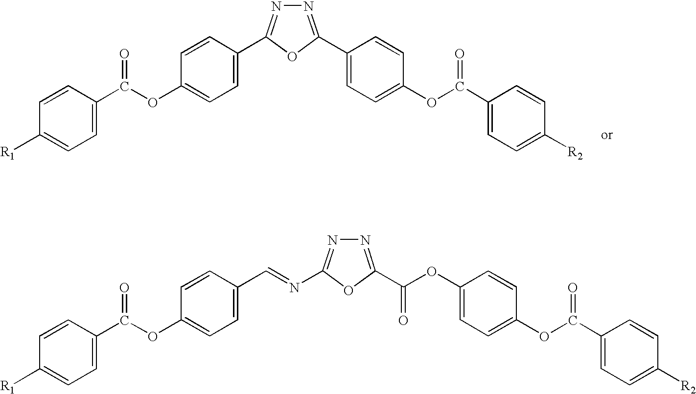
- the bent core liquid crystal displaying biaxial nematic phase comprises an oxadiazole molecule having the formula:
- R 1 and R 2 independently comprise a straight chain alkyl or substituted alkyl having from 5 to 20 carbon atoms.
- Additional bent core liquid crystal molecules suitable for use in the present embodiments include those shown in FIGS. 5 and 6 . These examples are not meant to be limiting but merely exemplary of suitable liquid crystal molecules.
- the speed of reorientation of the n director in the biaxial nematic phase has also been found, in one case, to be approximately 2 times faster than in the uniaxial phase of same material, as can be seen in FIG. 4 .
- FIG. 4 the response characteristics of the reorientation of the n director in a cell filled with bent-core liquid crystal is shown. While in the uniaxial nematic phase at 170° C. (right), the reorientation response time is approximately 15 ms, while in the biaxial nematic phase at 160° C. (left), it is found to be less than 7 ms.
- biaxial nematic phase offers an advantage even when used like a uniaxial nematic phase (i.e., exploiting the reorientation of n) in devices.
- the devices using biaxial nematic liquid crystal switch faster than the uniaxial nematic devices, irrespective of whether the electro-optical effects are realized through the reorientation of the m or n director.
- FIGS. 7 and 8 show an exemplary electro-optical device in accordance with one embodiment.
- a biaxial nematic liquid crystal 10 having n and m directors is positioned between a pair of opposing substrates 12 , 14 , which are preferably coated with an alignment layer (not shown), such as rubbed polyimide.
- Crossed polarizers 16 , 18 are positioned on either side of the substrates.
- the director n aligns along the rubbing direction of the alignment layer.
- the plane containing n and m is parallel to the substrates, as seen in FIG. 7 . This state reorients the polarized light 20 and allows it to be transmitted 22 through the second polarizer.
- n reorients vertically, while m remains unchanged, as seen in FIG. 8 , or takes up random orientation. Polarized light is prevented from passing through the second polarizer, resulting in a darkened state. This reorientation of n is used to create optical contrast and thus a display device. Such a device switches faster then a device based on uniaxial nematic liquid crystal as shown in FIG. 4( b ).
- biaxial nematic which may also be extended to the biaxial smectic phase that has been confirmed in bent-core materials, is in the fabrication of tunable biaxial retardation films.
- Such films have been employed to reduce light leakage at 45° to the polarizer and analyzer directions in LC devices.
- the use of biaxial nematic liquid crystal makes it relatively easy to fabricate retardation films that can be electrically tuned.
- biaxial retardation films are prepared by constructing multi-layered stacks of uniaxial liquid crystal layers including arrangements of distinct planar and vertically aligned liquid crystal layers with precise control of the thickness and director n orientation.
- the uniaxial optical axis is oriented in plane (planar) while in others it is perpendicular to the film's plane (vertical alignment).
- Composite films of this type behave as biaxial films of constant biaxiality but are cumbersome to produce at high cost. Moreover, once formed, the degree of biaxial retardation that it offers can not be altered.
- a uniformly aligned film, of the type shown in FIG. 2 of biaxial nematic phase of bent-core liquid crystal functions, by its very nature, as biaxial retardation film.
- the fabrication of such a film is essentially one step process of preparing one liquid crystal layer, and thus quite easy.
- an enormous advantage is that the retardation of such a biaxial nematic retardation film is tunable with the application of an electric field.
- An exemplary biaxial retardation film comprises two transparent substrates with optically transparent but electrically conducting electrodes deposited on them.
- the electrodes may be films of indium-tin-oxide (ITO) or conducting polymer.
- the conductor layer is covered with a polymer which is either treated with polarized UV or mechanically rubbed to produce liquid crystal alignment.
- Most common method used in the LC industry is a film of polyimide (PI) which is mechanically rubbed after processing it through a prescribed thermal cycle. The methods of deposition, thermal processing, and rubbing are known to those skilled in the art of making LC display devices.
- the substrates are then assembled in to a cell with a cell gap, the magnitude of which can be varied depending on the two birefringences of the biaxial nematic phase and desired retardation.
- the cell gap is typically fixed with the use of glass or plastic spherical or rod-shaped beads as spacers. Normally, the spacers are sprayed on to one of both surfaces before the substrates are assembled in to a cell.
- the cell is then filled with the selected liquid crystal, for example with A 103 shown in FIG. 5 .
- This compound aligns with n parallel to the rubbing direction and m in the plane of the cell but perpendicular to n.
- the cell offers fixed retardations to the two polarization of incident light.
- the devices architecture resembles the schematic drawing in FIG. 2 .
- the retardation offered by such devices can be controlled by applying a dc or ac electric field of different frequencies to control the orientation of m and/or n.
- These films act as tunable biaxial retardation films.
- the special feature of tenability and easy fabrication are possible only with the use of biaxial nematic liquid crystal.
- biaxial LC devices such as in beam steering, holographic, and optical communications to define and control beam polarization, wave front shaping, and phase and amplitude of electric field associated with propagating light beams. These materials can also be used in photonic crystals.
Abstract
Description

where R1 and R2 independently comprise a straight chain alkyl or substituted alkyl having from 5 to 20 carbon atoms. Additional bent core liquid crystal molecules suitable for use in the present embodiments include those shown in
Claims (22)


Priority Applications (1)
| Application Number | Priority Date | Filing Date | Title |
|---|---|---|---|
| US11/508,526 US7604850B2 (en) | 2005-08-24 | 2006-08-23 | Biaxial liquid crystal electro-optic devices |
Applications Claiming Priority (2)
| Application Number | Priority Date | Filing Date | Title |
|---|---|---|---|
| US71104605P | 2005-08-24 | 2005-08-24 | |
| US11/508,526 US7604850B2 (en) | 2005-08-24 | 2006-08-23 | Biaxial liquid crystal electro-optic devices |
Publications (2)
| Publication Number | Publication Date |
|---|---|
| US20070108408A1 US20070108408A1 (en) | 2007-05-17 |
| US7604850B2 true US7604850B2 (en) | 2009-10-20 |
Family
ID=37616930
Family Applications (1)
| Application Number | Title | Priority Date | Filing Date |
|---|---|---|---|
| US11/508,526 Expired - Fee Related US7604850B2 (en) | 2005-08-24 | 2006-08-23 | Biaxial liquid crystal electro-optic devices |
Country Status (2)
| Country | Link |
|---|---|
| US (1) | US7604850B2 (en) |
| WO (1) | WO2007025111A1 (en) |
Cited By (1)
| Publication number | Priority date | Publication date | Assignee | Title |
|---|---|---|---|---|
| US20120120984A1 (en) * | 2010-11-11 | 2012-05-17 | Ppg Industries Ohio, Inc. | Temperature sensitive composite for photonic crystals |
Families Citing this family (7)
| Publication number | Priority date | Publication date | Assignee | Title |
|---|---|---|---|---|
| KR101304411B1 (en) | 2007-05-03 | 2013-09-05 | 삼성디스플레이 주식회사 | Display device |
| KR101469039B1 (en) * | 2008-02-11 | 2014-12-04 | 삼성디스플레이 주식회사 | Liquid crystal composition and display device having the same |
| KR101490475B1 (en) * | 2008-06-25 | 2015-02-06 | 삼성디스플레이 주식회사 | Liquid crystal display and the driving method thereof |
| TWI417370B (en) * | 2008-12-01 | 2013-12-01 | Chunghwa Picture Tubes Ltd | Liquid crystal material and optical compensated bend mode display |
| DE102008063330A1 (en) | 2008-12-30 | 2010-07-01 | Technische Universität Chemnitz | New biaxially nematic liquid crystal ring compounds, e.g. (2,5-bis-hexyloxy-4-pyridin-3-yl-ethynyl-phenylethynyl)-phenyl-(1,3,4)thiadiazol-2-yl-phenylethynyl-2,5-bis-hexyloxy-phenylethynyl-phenoxy-acetic acid ethyl ester, useful in LCD |
| WO2011161663A1 (en) | 2010-06-25 | 2011-12-29 | The Provost, Fellows, Foundation Scholars, And The Other Members Of Board, Of The College Of The Holy And Undivided Trinity Of Queen Elizabeth, Near Dublin | Liquid crystal display devices |
| CN102645778B (en) * | 2012-03-08 | 2016-01-27 | 北京京东方光电科技有限公司 | A kind of display panels and preparation method thereof |
Citations (3)
| Publication number | Priority date | Publication date | Assignee | Title |
|---|---|---|---|---|
| EP0335348A2 (en) | 1988-03-28 | 1989-10-04 | Canon Kabushiki Kaisha | Mesomorphic compound, ferroelectric liquid crystal composition containing same and ferroelectric liquid crystal device |
| US6493055B1 (en) * | 1996-04-10 | 2002-12-10 | Sharp Kabushiki Kaisha | Homeo-tropically-oriented nematic liquid crystal material |
| WO2005019380A1 (en) | 2003-08-16 | 2005-03-03 | Cambridge University Technical Services Limited | Bistable ferroelectric liquid crystal cells and devices using siloxane oligmomers and the use thereof |
-
2006
- 2006-08-23 US US11/508,526 patent/US7604850B2/en not_active Expired - Fee Related
- 2006-08-23 WO PCT/US2006/033190 patent/WO2007025111A1/en active Application Filing
Patent Citations (3)
| Publication number | Priority date | Publication date | Assignee | Title |
|---|---|---|---|---|
| EP0335348A2 (en) | 1988-03-28 | 1989-10-04 | Canon Kabushiki Kaisha | Mesomorphic compound, ferroelectric liquid crystal composition containing same and ferroelectric liquid crystal device |
| US6493055B1 (en) * | 1996-04-10 | 2002-12-10 | Sharp Kabushiki Kaisha | Homeo-tropically-oriented nematic liquid crystal material |
| WO2005019380A1 (en) | 2003-08-16 | 2005-03-03 | Cambridge University Technical Services Limited | Bistable ferroelectric liquid crystal cells and devices using siloxane oligmomers and the use thereof |
Non-Patent Citations (16)
| Title |
|---|
| Acharya, B. R., et al., "Biaxial nematic phase in bent-core thermotropic mesogens", Physical Review Letters, vol. 92, No. 14, Apr. 9, 2004, pp. 145506-1-145506-4, The American Physical Society 2004. |
| Brand, H.R., et al., "The Biaxial Nematic-Smectic Cm Transition in Polymeric Liquid Crystals", Makromol. Chem. Rap. Comm. 12, 539 (1991) Federal Republic of Germany. |
| CAPLUS 2005: 557624. * |
| Cristiano, R., et al., "Light-emitting bent-shape liquid crystals", Liquid Crystals, Jan. 2005, vol. 32, No. 1, pp. 15-25, Taylor and Francis, Abingdon, GB, XP-001222749, ISSN: 0267-8292. |
| Diez, S., et al., "Dielectric studies of a laterally-linked siloxane ester dimer", Liquid Crystals, Sep. 2003, vol. 30, No. 9, pp. 1021-1030, Taylor and Francis, Abingdon, GB, XP-001169718. |
| Geoffrey R. Luckhurst, "A missing phase found at last?"; Nature, Jul. 22, 2004, pp. 413-414, vol. 430, Nature Publishing Group (USA). |
| Gortz et al., "Enantioselective segregation in achiral nematic liquid crystals", Chem. Commun., 2005, 3262-3264. * |
| Kirsten Severing, "A Biaxial Nematic Phase in a Thermotropic Liquid Crystalline Side-Chain Polymer," disseration, Mar. 2002-Jul. 2005, am Institut für Makromolekulare Chemie der Albert-Ludwigs-Universität Freiburg im Breisgau (Germany). |
| Klaus Praefcke, "Thermotropic Biaxial Nematics:[1] Highly Desirable Materials, Still Elusive?", Brazilian Journal of Physics, Jun. 2002, pp. 564-569, vol. 32, No. 2B (Brazil). |
| Lai, Chung K., et al., "Heterocyclic 1,3,4-oxadiazole as columnar core", Liquid Crystals, Jul. 2002, vol. 29, No. 7, pp. 915-920, Taylor and Francis, Abingdon, GB, XP-001125212, ISSN: 0267-8292. |
| Madsen, L.A., et al., "Thermotropic Biaxial Nematic Liquid Crystals", Physical Review Letters, vol. 92, No. 14, Apr. 9, 2004, pp. 145505-1-145505-4, The American Physical Society 2004. |
| Parra, M., et al., "New 1,2,4- and 1,3,4-oxadiazole materials: synthesis, and mesomorphic and luminescence properties", Liquid Crystals, Aug. 2006, vol. 33, No. 8, pp. 875-882, XP-001246007. |
| Parra, M., et al., "Symmetric esters derived from 1,3,4-oxadiazole: synthesis, mesomorphic properties and structural study by semi-empirical calculations", Liquid Crystals, Nov. 2002, vol. 29, No. 11, pp. 1375-1382, Taylor and Francis, Abingdon, GB, XP-001132301, ISSN: 0267-8292. |
| Ponomarenko, S.A., et al., "Liquid crystalline carbosilane dendrimers: First generation", Liquid Crystals, Jul. 1996, vol. 21, No. 1, pp. 1-12, Taylor and Francis, Abingdon, GB, XP-000599864. |
| Semmler, K. J.K., et al., "Biaxial smectic phases in non-linear mesogens: optical properties and phase behaviour of an oxadiazole liquid crystal", Liquid Crystals, Jun. 1998, vol. 24, No. 6, pp. 799-803, Taylor and Francis, Abingdon, GB, XP-000773002 ISSN: 0267-8292. |
| Su, C., et al., "Heterocyclic, 1,2,4-triazoles as calamitic mesogens", Liquid Crystals, May 2004, vol. 31, No. 5, pp. 745-749, Taylor and Francis, Abingdon, GB, XP-001192880, ISSN: 0267-8292. |
Cited By (2)
| Publication number | Priority date | Publication date | Assignee | Title |
|---|---|---|---|---|
| US20120120984A1 (en) * | 2010-11-11 | 2012-05-17 | Ppg Industries Ohio, Inc. | Temperature sensitive composite for photonic crystals |
| US9022648B2 (en) * | 2010-11-11 | 2015-05-05 | Prc-Desoto International, Inc. | Temperature sensitive composite for photonic crystals |
Also Published As
| Publication number | Publication date |
|---|---|
| WO2007025111A1 (en) | 2007-03-01 |
| US20070108408A1 (en) | 2007-05-17 |
Similar Documents
| Publication | Publication Date | Title |
|---|---|---|
| US7604850B2 (en) | Biaxial liquid crystal electro-optic devices | |
| US4239345A (en) | Bistable liquid crystal twist cell | |
| Wu | Infrared properties of nematic liquid crystals: an overview | |
| US8330931B2 (en) | Flexoelectro-optic liquid crystal device | |
| Jain et al. | An overview of polymer-dispersed liquid crystals composite films and their applications | |
| Cui et al. | Alignment layers with variable anchoring strengths from Polyvinyl Alcohol | |
| KR100430739B1 (en) | Liquid crystal device and display | |
| JPH10333171A (en) | Liquid crystal display device | |
| JP2004163866A (en) | Liquid crystal device | |
| US4776674A (en) | Liquid crystal device with chemically-induced high-tilt alignment coating | |
| JPH0933957A (en) | Liquid-crystal display device | |
| Gupta et al. | Ferroelectric liquid crystals: futuristic mesogens for photonic applications | |
| US7034907B2 (en) | Stressed liquid crystals as an ultra-fast light modulating material consisting of unidirectionally oriented liquid crystal micro-domains separated by polymer chains | |
| JP3477678B2 (en) | Display device and electro-optical device using colloidal liquid crystal composite material | |
| Park et al. | Director tilting of liquid crystals on photoisomerizable polyimide alignment layers doped with homeotropic surfactant | |
| US9400412B2 (en) | Nanosecond liquid crystalline optical modulator | |
| KR960002689B1 (en) | Liquid crystal electro-optic device | |
| He et al. | Polarization properties of an amplitude nematic liquid crystal grating | |
| KR19990028998A (en) | Optical member including a liquid crystal display device and a polarizer | |
| Jo et al. | Inverse four-domain twisted nematic liquid crystal display fabricated by the enhancement of azimuthal anchoring energy | |
| TWI320126B (en) | Negative retardation film | |
| Cheng | Liquid crystal display—present status and emerging technology | |
| KR100280636B1 (en) | Liquid crystal display | |
| Uzorka | Enhancement of the chiral optical properties | |
| Hinov et al. | Observation of transient alignment-inversion walls in nematics of phenyl benzoates in the presence of a magnetic field |
Legal Events
| Date | Code | Title | Description |
|---|---|---|---|
| AS | Assignment |
Owner name: KENT STATE UNIVERSITY, OHIO Free format text: ASSIGNMENT OF ASSIGNORS INTEREST;ASSIGNOR:KUMAR, SATYENDRA NMI;REEL/FRAME:018364/0231 Effective date: 20061005 Owner name: KENT STATE UNIVERSITY,OHIO Free format text: ASSIGNMENT OF ASSIGNORS INTEREST;ASSIGNOR:KUMAR, SATYENDRA NMI;REEL/FRAME:018364/0231 Effective date: 20061005 |
|
| AS | Assignment |
Owner name: NATIONAL SCIENCE FOUNDATION, VIRGINIA Free format text: CONFIRMATORY LICENSE;ASSIGNOR:KENT STATE UNIVERSITY;REEL/FRAME:025571/0038 Effective date: 20101025 |
|
| FPAY | Fee payment |
Year of fee payment: 4 |
|
| REMI | Maintenance fee reminder mailed | ||
| LAPS | Lapse for failure to pay maintenance fees |
Free format text: PATENT EXPIRED FOR FAILURE TO PAY MAINTENANCE FEES (ORIGINAL EVENT CODE: EXP.) |
|
| STCH | Information on status: patent discontinuation |
Free format text: PATENT EXPIRED DUE TO NONPAYMENT OF MAINTENANCE FEES UNDER 37 CFR 1.362 |
|
| FP | Lapsed due to failure to pay maintenance fee |
Effective date: 20171020 |