US7651548B2 - Discharge device and air purification device - Google Patents
Discharge device and air purification device Download PDFInfo
- Publication number
- US7651548B2 US7651548B2 US10/588,455 US58845505A US7651548B2 US 7651548 B2 US7651548 B2 US 7651548B2 US 58845505 A US58845505 A US 58845505A US 7651548 B2 US7651548 B2 US 7651548B2
- Authority
- US
- United States
- Prior art keywords
- discharge
- voltage
- electrodes
- frequency
- streamer
- Prior art date
- Legal status (The legal status is an assumption and is not a legal conclusion. Google has not performed a legal analysis and makes no representation as to the accuracy of the status listed.)
- Expired - Fee Related, expires
Links
Images


Classifications
-
- B—PERFORMING OPERATIONS; TRANSPORTING
- B01—PHYSICAL OR CHEMICAL PROCESSES OR APPARATUS IN GENERAL
- B01D—SEPARATION
- B01D53/00—Separation of gases or vapours; Recovering vapours of volatile solvents from gases; Chemical or biological purification of waste gases, e.g. engine exhaust gases, smoke, fumes, flue gases, aerosols
- B01D53/32—Separation of gases or vapours; Recovering vapours of volatile solvents from gases; Chemical or biological purification of waste gases, e.g. engine exhaust gases, smoke, fumes, flue gases, aerosols by electrical effects other than those provided for in group B01D61/00
-
- F—MECHANICAL ENGINEERING; LIGHTING; HEATING; WEAPONS; BLASTING
- F24—HEATING; RANGES; VENTILATING
- F24F—AIR-CONDITIONING; AIR-HUMIDIFICATION; VENTILATION; USE OF AIR CURRENTS FOR SCREENING
- F24F8/00—Treatment, e.g. purification, of air supplied to human living or working spaces otherwise than by heating, cooling, humidifying or drying
- F24F8/10—Treatment, e.g. purification, of air supplied to human living or working spaces otherwise than by heating, cooling, humidifying or drying by separation, e.g. by filtering
- F24F8/192—Treatment, e.g. purification, of air supplied to human living or working spaces otherwise than by heating, cooling, humidifying or drying by separation, e.g. by filtering by electrical means, e.g. by applying electrostatic fields or high voltages
-
- H—ELECTRICITY
- H01—ELECTRIC ELEMENTS
- H01T—SPARK GAPS; OVERVOLTAGE ARRESTERS USING SPARK GAPS; SPARKING PLUGS; CORONA DEVICES; GENERATING IONS TO BE INTRODUCED INTO NON-ENCLOSED GASES
- H01T19/00—Devices providing for corona discharge
-
- Y—GENERAL TAGGING OF NEW TECHNOLOGICAL DEVELOPMENTS; GENERAL TAGGING OF CROSS-SECTIONAL TECHNOLOGIES SPANNING OVER SEVERAL SECTIONS OF THE IPC; TECHNICAL SUBJECTS COVERED BY FORMER USPC CROSS-REFERENCE ART COLLECTIONS [XRACs] AND DIGESTS
- Y02—TECHNOLOGIES OR APPLICATIONS FOR MITIGATION OR ADAPTATION AGAINST CLIMATE CHANGE
- Y02A—TECHNOLOGIES FOR ADAPTATION TO CLIMATE CHANGE
- Y02A50/00—TECHNOLOGIES FOR ADAPTATION TO CLIMATE CHANGE in human health protection, e.g. against extreme weather
- Y02A50/20—Air quality improvement or preservation, e.g. vehicle emission control or emission reduction by using catalytic converters
-
- Y—GENERAL TAGGING OF NEW TECHNOLOGICAL DEVELOPMENTS; GENERAL TAGGING OF CROSS-SECTIONAL TECHNOLOGIES SPANNING OVER SEVERAL SECTIONS OF THE IPC; TECHNICAL SUBJECTS COVERED BY FORMER USPC CROSS-REFERENCE ART COLLECTIONS [XRACs] AND DIGESTS
- Y10—TECHNICAL SUBJECTS COVERED BY FORMER USPC
- Y10S—TECHNICAL SUBJECTS COVERED BY FORMER USPC CROSS-REFERENCE ART COLLECTIONS [XRACs] AND DIGESTS
- Y10S323/00—Electricity: power supply or regulation systems
- Y10S323/903—Precipitators
Definitions
- the present invention relates to a discharge device which causes a streamer discharge to be initiated upon application of a cyclically varying voltage, and to an air purification device which is equipped with such a discharge device.
- Air purification devices which are equipped with discharge devices are conventionally utilized as means for decomposing and removing, by the use of a plasma generated by electric discharge, odorous components, harmful components, and other substances.
- an air purification device of the streamer discharge type in which a low temperature plasma is generated by streamer discharge is a preferable technique for decomposing and deodorizing harmful components because of its high air purification efficiency with relatively less electric power consumption.
- the above streamer discharge type air purification device includes, as a discharge device, a plurality of discharge electrodes, a counter electrode facing the plurality of discharge electrodes, and an electric power supply means configured to apply a voltage to both the discharge and counter electrodes.
- a streamer discharge is produced between both the electrodes, thereby generating a low temperature plasma. Harmful components and odorous components contained in air to be treated are brought into aeration contact with activated species (fast electron, ion, radical, other excited molecule et cetera) produced as a result of generation of the low temperature plasma, whereby these components are decomposed and removed (see Patent Document I).
- Such a streamer discharge type discharge device provides high decomposition efficiency for odorous components and harmful components, but on the other hand it has the property that the streamer discharge state (e.g. the frequency of occurrence of streamer discharges and the streamer discharge generation status) is acutely susceptible to being easily influenced by various affectors. If, in consequence of either dimensional or assembly errors made during fabrication of discharge electrodes, or dust adhesion between electrodes, the electrodes vary from each other in discharge characteristic, there arises a problem that streamer discharges are not produced stably.
- the streamer discharge state e.g. the frequency of occurrence of streamer discharges and the streamer discharge generation status
- FIG. 10 graphically represents discharge characteristics exhibited, respectively, by a plurality of electrodes (a, b, c), wherein the abscissa axis is indicative of the applied voltage (V) which is impressed to the plurality of electrodes and the ordinate axis is indicative of the discharge current (I) which flows at the time of electric discharge.
- these electrodes (a, b, c) vary from each other in discharge characteristic because of the reason described above. If, in such a condition, a predetermined applied voltage (for example, V 1 of FIG. 10 ) is fed to each electrode, this may result in a state in which some electrode (for example, the electrode (c) of FIG.
- Patent Document I JP 2002-336689A
- Patent Document II JP 2003-53129A
- a leader ( 53 ) which is a minute arc is generated from a discharge electrode ( 41 ) towards a counter electrode ( 42 ).
- a leader ( 53 ) which is a minute arc is generated from a discharge electrode ( 41 ) towards a counter electrode ( 42 ).
- air is ionized into an electron ( 51 ) and a charged particle ( 52 ) by a strong electric potential gradient.
- the charged particle ( 52 ) reaches the counter electrode's ( 42 ) side, a single electric discharge is completed.
- the electron ( 51 ) resulting from ionization moves in the direction of the discharge electrode ( 41 ), while on the other hand the charged particle ( 52 ) moves in the direction of the counter electrode ( 42 ) ( FIG. 5(A) ).
- the charged particle ( 52 ) as a result of ionization is relatively large in mass, in comparison with the electron ( 51 ). Consequently, the charged particle ( 52 ) is slower in movement speed than the electron ( 51 ), which means that in a single streamer discharge the charged particle ( 52 ) is temporarily left behind between both the electrodes ( 41 , 42 ) ( FIG. 5(B) ).
- FIG. 6 is a graph which represents the temporal variation in occurrence characteristic of the streamer discharge in a discharge device in which a cyclically varying voltage (Vp) is applied.
- Vp cyclically varying voltage
- the abscissa axis is indicative of the time (t) and the ordinate axis is indicative of the applied voltage (V).
- the discharge electrode has a characteristic of causing a streamer discharge to be initiated upon application of a voltage equal to or higher than, for example, (Vmin).
- the voltage (Vp) may not exceed (Vmin) after an elapse of the discharge cycle (Ts) (for example, at time t 2 of FIG. 6 ).
- the next streamer discharge is not provided at time t 2 , but at time t 3 at which the voltage (Vp) reaches above (Vmin) for the first time after an elapse of the discharge cycle (Ts).
- the time from t 2 until t 3 becomes a discharge delay time, thereby causing discharge losses in the electrodes ( 41 , 42 ).
- an object of the present invention is to provide an improved discharge device in which a cyclically varying voltage is applied. More specifically, the present invention intends to accomplish a reduction in discharge loss between both the electrodes, thereby making it possible to stably produce streamer discharges.
- a first invention provides a discharge device, which comprises a plurality of discharge electrodes and a counter electrode facing the plurality of discharge electrodes, for causing a streamer discharge to be initiated between both the electrodes by applying a cyclically varying voltage to both the electrodes from an electric power supply means.
- the discharge device of the first invention is characterized in that the following relational expression is satisfied: fv ⁇ fs where (fv) is the frequency of the voltage which is applied to both the electrodes and (fs) is the frequency of the streamer discharge which is generated, in the form of a pulse, between both the electrodes.
- streamer discharge frequency (fs) is the frequency of a streamer discharge that is generated in the form of a pulse by the lingering charged particle ( 52 ) (see FIG. 6 ), in other words the streamer discharge frequency (fs) means the reciprocal of the foregoing discharge cycle (Ts).
- the cyclically varying voltage frequency (fv) becomes equal to or higher than the streamer discharge frequency (fs) and is then applied from the electric power supply means ( 45 ) to both the electrodes ( 41 , 42 ).
- the cycle of the cyclically varying voltage (the voltage cycle (Tv)) becomes equal to or lower than the discharge cycle (Ts). If, in such a condition, a streamer discharge is produced, this makes it possible to further reduce the discharge delay time at the time of streamer discharge (period indicated by dashed arrow in FIG. 7 ), as compared to the case where the voltage cycle (Tv) is in excess of the discharge cycle (Ts).
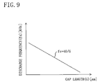
- the voltage frequency (fv) which becomes equal to or higher than the discharge frequency (fs) is determined based on the distance (G) (gap length) between both the electrodes, and a voltage having this voltage frequency (fv) is applied by the electric power supply means ( 45 ) to both the electrodes ( 41 , 42 ).
- a streamer discharge is generated in the form of a pulse due to the lingering charged particle ( 52 ). Consequently, the lingering time of the charged particle ( 52 ) decreases with decreasing the distance for the charged particle ( 52 ) to reach the counter electrode ( 42 ), i.e. the gap length (G), and the discharge frequency (fs) increases. On the other hand, the lingering time of the charged particle ( 52 ) increases with increasing the gap length (G), and the discharge frequency (fs) decreases. In this way, the streamer discharge frequency (fs) is strongly governed by the gap length (G), and the discharge frequency (fs) can be roughly estimated from the gap length (G).
- a third invention provides a discharge device according to the first or second invention, the third invention being characterized in that the following relational expression is satisfied: fv ⁇ 20[kHz] where (fv)[kHz] is the frequency of the voltage which is applied to both the electrodes.
- a voltage is applied from the electric power supply means ( 45 ) to both the electrodes ( 41 , 42 ) at the voltage frequency (fv) not less than the discharge frequency (fs) and not less than 20[kHz].
- the streamer discharge frequency (fs) is less than 20[kHz], so that if the voltage frequency (fv) is made equal to or higher than 20[kHz], this ensures that the voltage frequency (fv) is not less than the discharge frequency (fs) without failing. Accordingly, the discharge delay time (period indicated by dashed arrow in FIG. 6 ) at the time of streamer discharge can be reduced.
- a fourth invention provides a discharge device according to one of the first to third inventions, the fourth invention being characterized in that the following relational expression is satisfied: V p - p ⁇ 0.1 ⁇ V a where (Va) and (Vp-p) are, respectively, the average voltage and the amplitude for the voltage which is applied to both the electrodes.
- a voltage that cyclically varies at the amplitude (Vp-p) equal to or lower than 10% of the average voltage (Va) is applied by the electric power supply means ( 45 ) to both the voltages ( 41 , 42 ). Consequently, the range of variation of the voltage that is applied to both the electrodes ( 41 , 42 ) is made equal to or lower than 10% of the average voltage (Va).
- the streamer discharge has such a characteristic that sparks are produced more easily when compared to the electric discharge such as electric precipitation.
- the range of variation of the voltage that is applied to both the electrodes ( 41 , 42 ) is narrowed so as to fall below 10% of the average voltage (Va), thereby keeping the voltage that is applied to both the electrodes ( 41 , 42 ) from increasing and reaching a spark region, whereby the generation of a spark is inhibited.
- a fifth invention provides an air purification device, which comprises a discharge device for causing a streamer discharged to be initiated between a discharge electrode and a counter electrode, for purifying air to be treated by distributing the air to be treated between both the electrodes.
- the fifth invention is characterized in that the aforesaid discharge device is any one of the discharge devices according to the first to fourth inventions.
- the fifth invention provides an air purifying device to which the discharge device according to any one of the first to fourth inventions is applied. Therefore, the discharge delay time at the time of streamer discharge in the air purification device can be reduced.
- the first invention it is arranged such that a voltage whose voltage frequency (fv) is equal to or higher than the discharge frequency (fs) is applied to both the electrodes ( 41 , 42 ).
- a voltage whose voltage frequency (fv) is equal to or higher than the discharge frequency (fs) is applied to both the electrodes ( 41 , 42 ).
- the discharge delay time caused at the time of streamer discharge is reduced. Consequently, the discharge loss is suppressed in both the electrodes ( 41 , 42 ), thereby making it possible to stably generate streamer discharges.
- the voltage frequency (fv) is determined based on the discharge frequency (fs) estimated from the gap length (G).
- This arrangement ensures that the voltage frequency (fv) is made equal to or higher than the discharge frequency (fs), thereby making it possible to reduce the discharge delay time at the time of streamer discharge. This therefore ensures that the discharge losses of the discharge device are suppressed without failing.
- the third invention it is arranged such that a voltage, whose voltage frequency (fv) is not less than the discharge frequency (fs) and not less than 20[kHz], is applied. Consequently, the voltage frequency (fv) is made equal to or higher than the discharge frequency of a general streamer discharge (less than about 20 [kHz]), thereby making it possible to reduce the discharge delay time at the time of streamer discharge.
- the fourth invention it is arranged such that the amplitude (Vp-p) of the cyclically varying voltage is made equal to or lower than 10% of the average voltage (Va).
- This arrangement narrows the range of variation of the voltage that is applied to both the electrodes ( 41 , 42 ), thereby making it possible to prevent the voltage that is applied to both the electrodes ( 41 , 42 ) from reaching a spark region. As a result, the generation of a spark is inhibited and the streamer discharge stability of the discharge device is improved.
- the fifth invention by incorporating a discharge device according to any one of the first to fourth inventions into an air purification device, it becomes possible to reduce the discharge delay time at the time of streamer discharge in the air purification device. This reduces the discharge losses of the air purification device, thereby making it possible to stably generate streamer discharges. Accordingly, the air purification efficiency of the air purification device can be improved.
- FIG. 1 is a schematic perspective view which illustrates the overall construction of an air purification device according to an embodiment of the present invention
- FIG. 2 is a constructional diagram which illustrates the inside of a discharge device according to the embodiment when viewed from above;
- FIG. 3 is a perspective view which illustrates in enlarged manner a main section of the discharge device of the embodiment
- FIG. 4 is a circuit diagram for an electric power supply means of the embodiment
- FIG. 5 is a diagram which provides a description of the principle of streamer discharge
- FIG. 6 is a graph example which represents a discharge frequency versus voltage frequency relationship
- FIG. 7 is a graph example which represents a discharge frequency versus voltage frequency relationship
- FIG. 8 shows a simulation result derived by examining how the relationship between discharge frequency and voltage frequency affects the discharge delay time
- FIG. 9 is a graph which represents a gap length versus discharge frequency relationship
- FIG. 10 is a diagram which provides a description of the discharge characteristic of a conventional discharge device.
- FIG. 11 is a diagram which provides a description of the discharge characteristic when a cyclically varying voltage is applied.
- FIGS. 1-4 An embodiment of the present invention is described with reference to FIGS. 1-4 .
- FIG. 1 is a perspective view which illustrates in exploded manner an air purification device ( 10 ) according to the present embodiment
- FIG. 2 is a diagram which shows the inside of the air purification device ( 10 ) when viewed from above.
- This air purification device ( 10 ) is a consumer air purification device intended for use in general household and small stores.
- the air purification device ( 10 ) is an air purification device of the so-called streamer discharge type adapted to generate a low temperature plasma by streamer discharge and purify air to be treated with the aid of the low temperature plasma.
- the air purification device ( 10 ) includes a casing ( 20 ).
- the casing ( 20 ) is made up of a box-like casing main body ( 21 ) with an open end surface and a front plate ( 22 ) which is placed on the open end surface.
- An air suction opening ( 23 ) is formed in each side surface of the casing ( 20 ) on the side of the front plate ( 22 ).
- an air blowout opening ( 24 ) is formed in the top plate of the casing main body ( 21 ). More specifically, the air blowout opening ( 24 ) is located adjacent to the rear plate of the casing main body ( 21 ).
- An air passageway ( 25 ) is formed within the casing ( 20 ).
- the air passageway ( 25 ) extends from the air suction opening ( 23 ) to the air blowout opening ( 24 ).
- a stream of room air which is the air to be treated is made to flow through the air passageway ( 25 ).
- a functional section ( 30 ) including various air purification components, and a centrifugal air blower ( 26 ) configured to cause room air to be distributed through the air passageway ( 25 ) are disposed in the air passageway ( 25 ) in that order in the direction from the upstream side (the bottomside in FIG. 2 ) to the downstream side of the flow of the room air.
- a discharge device ( 40 ) configured to cause a low temperature plasma to be generated is integrally incorporated into the ionization part ( 32 ).
- an electric power supply means ( 45 ) for the discharge device ( 40 ) is provided in the casing main body ( 21 ) of the air purification device ( 10 ). More specifically, the electric power supply means ( 45 ) is located adjacent to the rear bottomside of the casing main body ( 21 ).
- the pre-filter ( 31 ) is formed by a filter adapted to entrap and collect dust of relatively large size contained in the air.
- the ionization part ( 32 ) causes dust of relatively small size passing through the pre-filter ( 31 ) to be charged electrically.
- the electrically charged dust is entrapped and collected by the electrostatic filter ( 33 ) disposed downstream of the ionization part ( 32 ).
- the ionization part ( 32 ) is made up of a plurality of ionization lines ( 35 ) and a plurality of counter electrodes ( 42 ).
- the plurality of ionization lines ( 35 ) extend between the top end and the bottom end of the ionization part ( 32 ) at even intervals.
- Each ionization line ( 35 ) lies on a single virtual surface in parallel with the electrostatic filter ( 33 ).
- the counter electrode ( 42 ) is formed by an elongated member having a cross section in the shape of a Japanese katakana character “ (ko)” (like a rectangular shape with one side missing or open), and its open part is located on the rear side.
- Each counter electrode ( 42 ) is arranged between ionization lines ( 35 ), such that it is positioned parallel to the ionization lines ( 35 ). And, each counter electrode ( 42 ) is joined, at its open part, to a single mesh plate ( 37 ).
- the discharge device ( 40 ) is equipped with a plurality of discharge electrodes ( 41 ) and a counter electrode ( 42 ) facing the discharge electrodes ( 41 ).
- This counter electrode ( 42 ) is shared as the counter electrode ( 42 ) of the ionization part ( 32 ), and the discharge electrodes ( 41 ) are positioned in the inside of the associated counter electrode ( 42 ) facing the discharge electrodes ( 41 ).
- FIG. 3 is an enlarged perspective view of the discharge device ( 40 ).
- an electrode holding member ( 43 ) extending vertically is provided in the inside of the counter electrode ( 42 ).
- the discharge electrode ( 41 ) is held by a fixing member ( 44 ) to the electrode holding member ( 43 ).
- the discharge electrode ( 41 ) is a linear or rod-like electrode.
- the discharge electrode ( 41 ) projecting outwardly from the fixing member ( 44 ) is arranged, such that it runs substantially parallel with a first surface ( 42 a ) of the counter electrode ( 42 ).
- the distance between the tip of the discharge electrode ( 41 ) and the first surface ( 42 a ) of the counter electrode ( 42 ), i.e. the gap length (G), is 4.8 [mm] in the present embodiment.
- the catalytic filter ( 34 ) is disposed downstream of the electrostatic filter ( 33 ).
- the catalytic filter ( 34 ) is formed, for example, by a honeycomb structure substrate which supports on its surface a catalyst.
- catalysts such as catalysts of the manganese family and catalysts of the precious metal family
- These catalysts are capable of further activating high-reactivity substances present in a low temperature plasma generated by electric discharge and capable of promoting the decomposition of harmful substances and odorous substances in the air.
- the electric power supply means ( 45 ) is made up of a high voltage power supply control part ( 61 ) and a high voltage power supply circuit part ( 62 ).
- the high voltage power supply control part ( 61 ) and the high voltage power supply circuit part ( 62 ) are connected together.
- the high voltage power supply circuit part ( 62 ) is connected to the discharge electrode ( 41 ) and to the counter electrode ( 42 ).
- the high voltage power supply control part ( 61 ) includes a high voltage power supply ( 63 ) which is a primary side power supply, and a controller ( 64 ) for controlling the high voltage power supply circuit part ( 62 ).
- the high voltage power supply circuit part ( 62 ) includes an oscillating circuit ( 65 ), a transistor ( 66 ), a transformer part ( 67 ), and a smoothing circuit ( 68 ).
- the oscillating circuit ( 65 ) applies a voltage (oscillating signal) to the transistor ( 66 ) whereby the transistor ( 66 ) is turned on or off.
- the transformer part ( 67 ) applies a cyclically varying voltage to the smoothing circuit ( 68 ).
- the transformer part ( 67 ) has, on the primary side (oscillating circuit side), a primary side first coil (S 11 ) and a primary side second coil (S 12 ).
- the transformer part ( 67 ) has, on the secondary side (smoothing circuit side), a secondary side first coil (S 21 ).
- the primary side first coil (S 11 ) is repeatedly made conductive/non-conductive by the on/off of the transistor ( 66 ), whereby a boosted, amplitude-increased voltage is generated in the secondary side first coil (S 21 ).
- an induced voltage depending on the secondary side voltage is generated, and the induced voltage is detected by an output voltage detecting part ( 69 ).
- the output voltage detecting part ( 69 ) is configured, such that it sends out an abnormal signal to the controller ( 64 ), for example, when the secondary side output voltage is abnormal.
- the smoothing circuit ( 68 ) is formed by, for example, a Cockcroft circuit which is a capacitor/diode combination.
- the smoothing circuit ( 68 ) is configured, such that it smoothens a voltage boosted and amplified in the secondary side first coil (S 21 ) of the transfer part ( 67 ) and applies a cyclically varying voltage to both the electrodes ( 41 , 42 ) of the discharge device ( 40 ).
- the output waveform of a voltage which is applied to both the electrodes ( 41 , 42 ) is in the form of a sinusoidal wave, as shown in FIG. 7 .
- the cycle of this voltage (the voltage cycle (Tv)) is equal to or lower than the cycle of a pulsing streamer discharge (the discharge cycle (Ts)). That is, the frequency of a voltage which is applied to both electrodes ( 41 , 42 ) (the voltage frequency (fv)) is equal to or higher than the frequency of a pulsing streamer discharge (the discharge frequency (fs)).
- the voltage frequency (fv) is equal to or higher than 8.4[kHz].
- the amplitude of the voltage (Vp-p) is equal to or lower than 10% of the average voltage (Va) which is outputted from the electric power supply means ( 45 ).
- the average voltage (Va) is 4.0[kV] and the voltage amplitude (Vp-p) is equal to or lower than 0.4[kV].
- the centrifugal air blower ( 26 ) is activated whereby room air flows through the air passageway ( 25 ) in the casing ( 20 ).
- the electric power supply means ( 45 ) applies a voltage to the ionization part ( 32 ) and to the discharge device ( 40 ).
- a voltage in the form of a sinusoidal wave is applied to the discharge device ( 40 ).
- a low temperature plasma is generated from the tip of the discharge electrode ( 41 ) towards the counter electrode ( 42 ) ( FIG. 3 ) and, as a result, activated species of high reactivity such as electron, ion, ozone, and radical et cetera are produced.
- activated species of high reactivity such as electron, ion, ozone, and radical et cetera are produced.
- these activated species arrive at the catalytic filter ( 34 ), they become further activated, thereby decomposing and removing harmful components and odorous components in the air. And, clean room air, free from dust as well as from harmful and odorous substances, is blown out into the room through the air blowout opening ( 24 ).
- the air purification device ( 10 ) of the present embodiment provides the following advantageous effects.
- the voltage frequency (fv) is made equal to or higher than the discharge frequency (fs). Consequently, in comparison with, for example, the case where the voltage frequency (fv) falls below the discharge frequency (fs) ( FIG. 6 ), the discharge delay time (period indicated by dashed arrow in FIG. 7 ) at the time of streamer discharge can be made shorter.
- FIG. 8 shows a simulation result derived by examining how the discharge delay time at the time of streamer discharge varies depending on the relationship between the voltage cycle (Tv) and the discharge cycle (Ts).
- the abscissa axis is indicative of values obtained by dividing the discharge cycle (Ts) by the voltage cycle (Tv), while on the other hand the ordinate axis is indicative of values obtained by dividing the discharge cycle (Ts) by the real discharge cycle (Ts′).
- the discharge cycle (Ts) is the minimum required cycle at the time of streamer discharge
- the real discharge cycle (Ts′) is the cycle which is required at the time of actual streamer discharge and is obtained by simulation.
- FIG. 8 shows that as (Ts/Ts′) on the ordinate axis approaches a value of 1.0, the discharge delay time decreases. Conversely, as (Ts/Ts′) on the ordinate axis approaches a value of 0, the discharge delay time increases.
- (Ts/Tv) ⁇ 1 in other words, it turns out that if the voltage cycle (Tv) becomes greater than the discharge cycle (Ts) the discharge delay time tends to significantly increase. Consequently, the discharge losses of the discharge device ( 40 ) increase.
- (Ts/Tv) ⁇ 1 in FIG. 8 i.e. if the voltage cycle (Tv) becomes equal to or less than the discharge cycle (Ts), the discharge delay time becomes relatively short. In other words, if the voltage frequency (fv) is made equal to or higher than the discharge frequency (fs), this reduces the discharge delay time, thereby making it possible to effectively reduce the discharge losses of the discharge device ( 40 ).
- the electric power supply means ( 45 ) is configured so as to be capable of application of a voltage which satisfies the relational expression: (fv) ⁇ 40/(G).
- this relational expression is described with reference to a graph of FIG. 9 .
- the discharge frequency (fs) is estimated from the above relational expression and the voltage frequency (fv) is determined based on the estimated discharge frequency (fs), thereby ensuring that the voltage frequency (fv) is made equal to or higher than the discharge frequency (fs).
- the discharge losses of the discharge device ( 40 ) can be reduced without failing.
- the electric power supply means ( 45 ) applies to both the electrodes ( 41 , 42 ) a voltage having an amplitude of (Vp-p) equal to or less than 10% of the average voltage (Va).
- Vp-p amplitude of the voltage which is applied to the both the electrodes ( 41 , 42 )
- the present invention may be configured as follows.
- the electric power supply means ( 45 ) is configured, such that it outputs a voltage whose voltage frequency (fv) is equal to or higher than 8.4[kHz].
- the voltage frequency (fv) is preferably equal to or higher than 20[kHz].
- the discharge delay time is reduced, thereby making it possible to reduce the discharge losses of the discharge device and, in addition, the frequency of sound associated with a voltage (amplitude signal) outputted from the electric power supply means ( 45 ) is made higher than the range of human hearing, thereby suppressing noises in the vicinity of the electric power supply means ( 45 ).
- the electric power supply means ( 45 ) outputs a voltage whose output waveform is a sinusoidal waveform.
- the output waveform of the electric power supply means ( 45 ) may be in any waveform such as rectangular waveform, saw-tooth waveform, pulse-like waveform et cetera as long as it varies cyclically.
- the present invention finds application in a discharge device adapted to cause a streamer discharge to be initiated by application of a cyclically varying voltage, and further finds application in an air purification device equipped with such a discharge device.
Abstract
Description
fv≧fs
where (fv) is the frequency of the voltage which is applied to both the electrodes and (fs) is the frequency of the streamer discharge which is generated, in the form of a pulse, between both the electrodes. Here, what is meant by “streamer discharge frequency (fs)” is the frequency of a streamer discharge that is generated in the form of a pulse by the lingering charged particle (52) (see
fv≧k/G
where (fv)[kHz] is the frequency of the voltage which is applied to both the electrodes and (G)[mm] is the distance between both the electrodes.
fv≧20[kHz]
where (fv)[kHz] is the frequency of the voltage which is applied to both the electrodes.
Vp-p≦0.1×Va
where (Va) and (Vp-p) are, respectively, the average voltage and the amplitude for the voltage which is applied to both the electrodes.
Claims (5)
fv≧fs
fv≧k/G
fv≧20[kHz]
Vp-p≧ 0.1×V a
Applications Claiming Priority (3)
| Application Number | Priority Date | Filing Date | Title |
|---|---|---|---|
| JP2004-032006 | 2004-02-09 | ||
| JP2004032006A JP3775417B2 (en) | 2004-02-09 | 2004-02-09 | Discharge device and air purification device |
| PCT/JP2005/001783 WO2005076424A1 (en) | 2004-02-09 | 2005-02-07 | Electric discharge device and air cleaner |
Publications (2)
| Publication Number | Publication Date |
|---|---|
| US20080314251A1 US20080314251A1 (en) | 2008-12-25 |
| US7651548B2 true US7651548B2 (en) | 2010-01-26 |
Family
ID=34836072
Family Applications (1)
| Application Number | Title | Priority Date | Filing Date |
|---|---|---|---|
| US10/588,455 Expired - Fee Related US7651548B2 (en) | 2004-02-09 | 2005-02-07 | Discharge device and air purification device |
Country Status (6)
| Country | Link |
|---|---|
| US (1) | US7651548B2 (en) |
| EP (1) | EP1715553A4 (en) |
| JP (1) | JP3775417B2 (en) |
| CN (1) | CN1906822B (en) |
| AU (1) | AU2005211052B8 (en) |
| WO (1) | WO2005076424A1 (en) |
Cited By (2)
| Publication number | Priority date | Publication date | Assignee | Title |
|---|---|---|---|---|
| US20110277627A1 (en) * | 2009-03-10 | 2011-11-17 | Sun-Tae An | Ion and ozone optimizing saturation method for indoor air |
| US20150143839A1 (en) * | 2012-07-05 | 2015-05-28 | Lg Electronics Inc. | Air conditioner |
Families Citing this family (6)
| Publication number | Priority date | Publication date | Assignee | Title |
|---|---|---|---|---|
| JP3840579B2 (en) * | 2005-02-25 | 2006-11-01 | ダイキン工業株式会社 | Air conditioner |
| GB0906091D0 (en) * | 2009-04-07 | 2009-05-20 | Snowball Malcolm R | None invasive disinfector |
| JP5533966B2 (en) * | 2012-09-14 | 2014-06-25 | ダイキン工業株式会社 | Air cleaner |
| JP6104630B2 (en) * | 2013-02-20 | 2017-03-29 | 株式会社 セテック | Power supply for sliding discharge |
| US20150343109A1 (en) | 2014-04-03 | 2015-12-03 | Novaerus Patent Limited | Coil Assembly for Plasma Generation |
| GB2526627A (en) * | 2014-05-30 | 2015-12-02 | Novaerus Patents Ltd | A plasma coil electrostatic precipitator assembly for air disinfection and pollution control |
Citations (31)
| Publication number | Priority date | Publication date | Assignee | Title |
|---|---|---|---|---|
| US1934923A (en) * | 1929-08-03 | 1933-11-14 | Int Precipitation Co | Method and apparatus for electrical precipitation |
| US2280330A (en) * | 1940-08-22 | 1942-04-21 | Research Corp | Power circuit for electrical precipitators |
| US3984215A (en) * | 1975-01-08 | 1976-10-05 | Hudson Pulp & Paper Corporation | Electrostatic precipitator and method |
| US4587475A (en) * | 1983-07-25 | 1986-05-06 | Foster Wheeler Energy Corporation | Modulated power supply for an electrostatic precipitator |
| EP0208822A1 (en) * | 1985-07-15 | 1987-01-21 | Kraftelektronik AB | An electrostatic dust precipitator |
| US4726812A (en) * | 1986-03-26 | 1988-02-23 | Bbc Brown, Boveri Ag | Method for electrostatically charging up solid or liquid particles suspended in a gas stream by means of ions |
| US4772998A (en) * | 1987-02-26 | 1988-09-20 | Nwl Transformers | Electrostatic precipitator voltage controller having improved electrical characteristics |
| US4976749A (en) * | 1989-04-24 | 1990-12-11 | Raytheon Company | Air filter and particle removal system |
| US5061296A (en) * | 1988-12-01 | 1991-10-29 | Crs Industries, Inc. | Air purification system |
| EP0508961A1 (en) * | 1991-04-12 | 1992-10-14 | ENEL S.p.A. | High-frequency switching-type protected power supply, in particular for electrostatic precipitators |
| US5159544A (en) * | 1988-12-27 | 1992-10-27 | Ransburg Corporation | High voltage power supply control system |
| US5401299A (en) * | 1993-02-26 | 1995-03-28 | Crs Industries, Inc. | Air purification apparatus |
| US5601633A (en) * | 1994-10-06 | 1997-02-11 | Ponizovsky; Lazar Z. | High voltage electrical method for removing ecologically noxious substances from gases |
| US5639294A (en) * | 1993-01-29 | 1997-06-17 | Abb Flakt Ab | Method for controlling the power supply to an electrostatic precipitator |
| WO1997035666A1 (en) | 1996-03-28 | 1997-10-02 | ABB Fläkt Aktiebolag | Method for controlling an electrostatic precipitator |
| US5707422A (en) * | 1993-03-01 | 1998-01-13 | Abb Flakt Ab | Method of controlling the supply of conditioning agent to an electrostatic precipitator |
| WO1998042444A1 (en) | 1997-03-26 | 1998-10-01 | ABB Fläkt Aktiebolag | Method to control current supply to an electrostatic precipitator |
| WO1999012649A1 (en) | 1997-09-10 | 1999-03-18 | ABB Fläkt Aktiebolag | Method to control current supply to an electrostatic precipitator |
| US5972076A (en) * | 1997-08-11 | 1999-10-26 | Nichols; Grady B. | Method of charging an electrostatic precipitator |
| JP2000058290A (en) | 1998-06-04 | 2000-02-25 | Keyence Corp | Static eliminator |
| JP2002336689A (en) | 2001-05-21 | 2002-11-26 | Daikin Ind Ltd | Plasma reactor and air cleaner |
| JP2003053129A (en) | 2001-05-28 | 2003-02-25 | Daikin Ind Ltd | Plasma type gas purifying apparatus and streamer discharge circuit |
| US6611440B1 (en) * | 2002-03-19 | 2003-08-26 | Bha Group Holdings, Inc. | Apparatus and method for filtering voltage for an electrostatic precipitator |
| US20050061152A1 (en) * | 2003-09-23 | 2005-03-24 | Msp Corporation | Electrostatic precipitator for diesel blow-by |
| US7041157B1 (en) * | 1999-11-10 | 2006-05-09 | Carl Maria Fleck | Filter system for spreading soot particles from a stream of exhaust gas |
| US20070193448A1 (en) * | 2004-03-18 | 2007-08-23 | Toshio Tanaka | Air purification device |
| US7270698B2 (en) * | 2003-06-05 | 2007-09-18 | Daikin Industries, Ltd. | Discharge device and air purifier |
| US7332020B2 (en) * | 2003-08-29 | 2008-02-19 | Daikin Industries, Ltd. | Gas treating device |
| US7377962B2 (en) * | 2003-08-29 | 2008-05-27 | Daikin Industries, Ltd. | Electric discharge device and air purifying device |
| US7465339B2 (en) * | 2004-07-02 | 2008-12-16 | Daikin Industries, Ltd. | Air purifier |
| US7497893B2 (en) * | 2002-06-21 | 2009-03-03 | Kronos Advanced Technologies, Inc. | Method of electrostatic acceleration of a fluid |
Family Cites Families (2)
| Publication number | Priority date | Publication date | Assignee | Title |
|---|---|---|---|---|
| KR100430345B1 (en) * | 2000-11-28 | 2004-05-04 | (주)에스이 플라즈마 | Apparatus for generating low temperature plasama at atmospheric pressure |
| CN1186113C (en) * | 2002-04-01 | 2005-01-26 | 山东中实股份有限公司 | Self-drying corona discharge process and equipment for cleaning fume |
-
2004
- 2004-02-09 JP JP2004032006A patent/JP3775417B2/en not_active Expired - Lifetime
-
2005
- 2005-02-07 EP EP05709835A patent/EP1715553A4/en not_active Ceased
- 2005-02-07 WO PCT/JP2005/001783 patent/WO2005076424A1/en active Application Filing
- 2005-02-07 CN CN200580001976XA patent/CN1906822B/en active Active
- 2005-02-07 AU AU2005211052A patent/AU2005211052B8/en active Active
- 2005-02-07 US US10/588,455 patent/US7651548B2/en not_active Expired - Fee Related
Patent Citations (33)
| Publication number | Priority date | Publication date | Assignee | Title |
|---|---|---|---|---|
| US1934923A (en) * | 1929-08-03 | 1933-11-14 | Int Precipitation Co | Method and apparatus for electrical precipitation |
| US2280330A (en) * | 1940-08-22 | 1942-04-21 | Research Corp | Power circuit for electrical precipitators |
| US3984215A (en) * | 1975-01-08 | 1976-10-05 | Hudson Pulp & Paper Corporation | Electrostatic precipitator and method |
| US4587475A (en) * | 1983-07-25 | 1986-05-06 | Foster Wheeler Energy Corporation | Modulated power supply for an electrostatic precipitator |
| EP0208822A1 (en) * | 1985-07-15 | 1987-01-21 | Kraftelektronik AB | An electrostatic dust precipitator |
| US4713093A (en) * | 1985-07-15 | 1987-12-15 | Kraftelektronik Ab | Electrostatic dust precipitator |
| US4726812A (en) * | 1986-03-26 | 1988-02-23 | Bbc Brown, Boveri Ag | Method for electrostatically charging up solid or liquid particles suspended in a gas stream by means of ions |
| US4772998A (en) * | 1987-02-26 | 1988-09-20 | Nwl Transformers | Electrostatic precipitator voltage controller having improved electrical characteristics |
| US5061296A (en) * | 1988-12-01 | 1991-10-29 | Crs Industries, Inc. | Air purification system |
| US5159544A (en) * | 1988-12-27 | 1992-10-27 | Ransburg Corporation | High voltage power supply control system |
| US4976749A (en) * | 1989-04-24 | 1990-12-11 | Raytheon Company | Air filter and particle removal system |
| EP0508961A1 (en) * | 1991-04-12 | 1992-10-14 | ENEL S.p.A. | High-frequency switching-type protected power supply, in particular for electrostatic precipitators |
| US5255178A (en) * | 1991-04-12 | 1993-10-19 | Enel S.P.A. | High-frequency switching-type protected power supply, in particular for electrostatic precipitators |
| US5639294A (en) * | 1993-01-29 | 1997-06-17 | Abb Flakt Ab | Method for controlling the power supply to an electrostatic precipitator |
| US5401299A (en) * | 1993-02-26 | 1995-03-28 | Crs Industries, Inc. | Air purification apparatus |
| US5707422A (en) * | 1993-03-01 | 1998-01-13 | Abb Flakt Ab | Method of controlling the supply of conditioning agent to an electrostatic precipitator |
| US5601633A (en) * | 1994-10-06 | 1997-02-11 | Ponizovsky; Lazar Z. | High voltage electrical method for removing ecologically noxious substances from gases |
| WO1997035666A1 (en) | 1996-03-28 | 1997-10-02 | ABB Fläkt Aktiebolag | Method for controlling an electrostatic precipitator |
| WO1998042444A1 (en) | 1997-03-26 | 1998-10-01 | ABB Fläkt Aktiebolag | Method to control current supply to an electrostatic precipitator |
| US5972076A (en) * | 1997-08-11 | 1999-10-26 | Nichols; Grady B. | Method of charging an electrostatic precipitator |
| WO1999012649A1 (en) | 1997-09-10 | 1999-03-18 | ABB Fläkt Aktiebolag | Method to control current supply to an electrostatic precipitator |
| JP2000058290A (en) | 1998-06-04 | 2000-02-25 | Keyence Corp | Static eliminator |
| US7041157B1 (en) * | 1999-11-10 | 2006-05-09 | Carl Maria Fleck | Filter system for spreading soot particles from a stream of exhaust gas |
| JP2002336689A (en) | 2001-05-21 | 2002-11-26 | Daikin Ind Ltd | Plasma reactor and air cleaner |
| JP2003053129A (en) | 2001-05-28 | 2003-02-25 | Daikin Ind Ltd | Plasma type gas purifying apparatus and streamer discharge circuit |
| US6611440B1 (en) * | 2002-03-19 | 2003-08-26 | Bha Group Holdings, Inc. | Apparatus and method for filtering voltage for an electrostatic precipitator |
| US7497893B2 (en) * | 2002-06-21 | 2009-03-03 | Kronos Advanced Technologies, Inc. | Method of electrostatic acceleration of a fluid |
| US7270698B2 (en) * | 2003-06-05 | 2007-09-18 | Daikin Industries, Ltd. | Discharge device and air purifier |
| US7332020B2 (en) * | 2003-08-29 | 2008-02-19 | Daikin Industries, Ltd. | Gas treating device |
| US7377962B2 (en) * | 2003-08-29 | 2008-05-27 | Daikin Industries, Ltd. | Electric discharge device and air purifying device |
| US20050061152A1 (en) * | 2003-09-23 | 2005-03-24 | Msp Corporation | Electrostatic precipitator for diesel blow-by |
| US20070193448A1 (en) * | 2004-03-18 | 2007-08-23 | Toshio Tanaka | Air purification device |
| US7465339B2 (en) * | 2004-07-02 | 2008-12-16 | Daikin Industries, Ltd. | Air purifier |
Cited By (3)
| Publication number | Priority date | Publication date | Assignee | Title |
|---|---|---|---|---|
| US20110277627A1 (en) * | 2009-03-10 | 2011-11-17 | Sun-Tae An | Ion and ozone optimizing saturation method for indoor air |
| US20150143839A1 (en) * | 2012-07-05 | 2015-05-28 | Lg Electronics Inc. | Air conditioner |
| US9746192B2 (en) * | 2012-07-05 | 2017-08-29 | Lg Electronics Inc. | Air conditioner |
Also Published As
| Publication number | Publication date |
|---|---|
| US20080314251A1 (en) | 2008-12-25 |
| JP3775417B2 (en) | 2006-05-17 |
| WO2005076424A1 (en) | 2005-08-18 |
| CN1906822A (en) | 2007-01-31 |
| AU2005211052A1 (en) | 2005-08-18 |
| CN1906822B (en) | 2010-07-14 |
| JP2005218748A (en) | 2005-08-18 |
| EP1715553A1 (en) | 2006-10-25 |
| AU2005211052B8 (en) | 2009-01-08 |
| EP1715553A4 (en) | 2009-03-18 |
| AU2005211052B2 (en) | 2008-07-17 |
Similar Documents
| Publication | Publication Date | Title |
|---|---|---|
| US7651548B2 (en) | Discharge device and air purification device | |
| US7270698B2 (en) | Discharge device and air purifier | |
| US7771671B2 (en) | Air conditioner device with partially insulated collector electrode | |
| EP2896410B1 (en) | Air-cleaning machine | |
| US7377962B2 (en) | Electric discharge device and air purifying device | |
| KR100358017B1 (en) | Exhaust Gas Purification System and Purification Method | |
| JP3839592B2 (en) | Air cleaner | |
| JP2003142228A (en) | Negative ion generating device | |
| JP7363058B2 (en) | Charging devices and electrostatic precipitators | |
| JP4706681B2 (en) | Discharge device and air purification device | |
| JP2003203746A (en) | Minus ion generating device and air purifying device | |
| JP3775421B2 (en) | Discharge device and air purification device | |
| KR100766215B1 (en) | Electric discharge device and air cleaner | |
| JP2005032710A (en) | Discharge device and air cleaning device | |
| JP2022153185A (en) | Ion generator and electric dust collector | |
| AU684300B2 (en) | Electronic purification of exhaust gases | |
| JP2005080835A (en) | Air cleaner | |
| JP2023134152A (en) | Discharge device and electric dust collector | |
| JP2005267874A (en) | Discharging device and air-cleaning device | |
| JPH0988559A (en) | Gas purifier | |
| JP2002273265A (en) | Air cleaning device |
Legal Events
| Date | Code | Title | Description |
|---|---|---|---|
| AS | Assignment |
Owner name: DAIKIN INDUSTRIES, LTD., JAPAN Free format text: ASSIGNMENT OF ASSIGNORS INTEREST;ASSIGNORS:TANAKA, TOSHIO;KAGAWA, KENKICHI;MOTEGI, KANJI;REEL/FRAME:018145/0121;SIGNING DATES FROM 20050329 TO 20050330 |
|
| FEPP | Fee payment procedure |
Free format text: PAYOR NUMBER ASSIGNED (ORIGINAL EVENT CODE: ASPN); ENTITY STATUS OF PATENT OWNER: LARGE ENTITY |
|
| FPAY | Fee payment |
Year of fee payment: 4 |
|
| FEPP | Fee payment procedure |
Free format text: MAINTENANCE FEE REMINDER MAILED (ORIGINAL EVENT CODE: REM.) |
|
| LAPS | Lapse for failure to pay maintenance fees |
Free format text: PATENT EXPIRED FOR FAILURE TO PAY MAINTENANCE FEES (ORIGINAL EVENT CODE: EXP.) |
|
| STCH | Information on status: patent discontinuation |
Free format text: PATENT EXPIRED DUE TO NONPAYMENT OF MAINTENANCE FEES UNDER 37 CFR 1.362 |
|
| FP | Lapsed due to failure to pay maintenance fee |
Effective date: 20180126 |