US7693233B2 - Parallel Tomlinson-Harashima precoders - Google Patents
Parallel Tomlinson-Harashima precoders Download PDFInfo
- Publication number
- US7693233B2 US7693233B2 US11/181,347 US18134705A US7693233B2 US 7693233 B2 US7693233 B2 US 7693233B2 US 18134705 A US18134705 A US 18134705A US 7693233 B2 US7693233 B2 US 7693233B2
- Authority
- US
- United States
- Prior art keywords
- parallel
- modulo
- output
- precoder
- compensation signal
- Prior art date
- Legal status (The legal status is an assumption and is not a legal conclusion. Google has not performed a legal analysis and makes no representation as to the accuracy of the status listed.)
- Active, expires
Links
Images


Classifications
-
- H—ELECTRICITY
- H04—ELECTRIC COMMUNICATION TECHNIQUE
- H04L—TRANSMISSION OF DIGITAL INFORMATION, e.g. TELEGRAPHIC COMMUNICATION
- H04L25/00—Baseband systems
- H04L25/02—Details ; arrangements for supplying electrical power along data transmission lines
- H04L25/03—Shaping networks in transmitter or receiver, e.g. adaptive shaping networks
- H04L25/03006—Arrangements for removing intersymbol interference
- H04L25/03343—Arrangements at the transmitter end
-
- H—ELECTRICITY
- H04—ELECTRIC COMMUNICATION TECHNIQUE
- H04L—TRANSMISSION OF DIGITAL INFORMATION, e.g. TELEGRAPHIC COMMUNICATION
- H04L25/00—Baseband systems
- H04L25/02—Details ; arrangements for supplying electrical power along data transmission lines
- H04L25/03—Shaping networks in transmitter or receiver, e.g. adaptive shaping networks
- H04L25/03006—Arrangements for removing intersymbol interference
- H04L2025/0335—Arrangements for removing intersymbol interference characterised by the type of transmission
- H04L2025/03356—Baseband transmission
- H04L2025/03363—Multilevel
Definitions
- the present invention relates to data processing and transmission. More particularly, it relates to parallel Tomlinson-Harashima precoding of data and parallel Tomlinson-Harashima precoders.
- Tomlinson-Harashima precoding is a transmitter equalization technique where equalization is performed at the transmitter side, and has been widely used in many communication systems. It can eliminate error propagation and allows use of capacity-achieving channel codes, such as low-density parity-check (LDPC) codes, in a natural way.
- LDPC low-density parity-check
- TH precoding has been proposed to be used in 10 Gigabit Ethernet over copper (10GBASE-T).
- the symbol rate of 10GBASE-T is 800 Mega Baud.
- a TH precoder contains feedback loops, and it may be impossible to clock the straightforward implementation of the TH precoder at such high speed.
- high speed design of TH precoders is of great interest.
- a TH precoder is similar to that of a DFE (decision feedback equalizer). The only difference is that a quantizer in the DFE is replaced with a modulo device in the TH precoder.
- a quantizer in the DFE is replaced with a modulo device in the TH precoder.
- the number of different outputs of the quantizer in the DFE is finite, which is usually equal to the size of the symbol alphabet, i.e., M.
- M the number of different outputs of the modulo device in the TH precoder is infinite for a floating-point implementation. For a fixed-point implementation, it is exponential with the wordlength. In some applications, the wordlength can be very large.
- the present invention provides a fast TH precoder through parallel processing and a method for designing the parallel TH precoder.
- a TH precoder is first converted to its equivalent form where the TH precoder can be viewed as an IIR filter with an input equal to the sum of the original input to the TH precoder and a finite-level compensation signal.
- a parallel IIR filter is obtained by applying classical look-ahead techniques to the equivalent IIR filter.
- the resulting parallel IIR filter is reformulated as an intermediate parallel Tomlinson-Harashima precoder by removing the compensation signal as an explicit input to the IIR filter.
- precomputation technique is applied to the intermediate design, resulting in a parallel Tomlinson-Harashima precoder.
- FIG. 1 a illustrates a zero-forcing pre-equalization function.
- FIG. 1 b illustrates a Tomlinson-Harashima (TH) precoding function.
- FIG. 1 c illustrates an equivalent form of a TH precoder function.
- FIG. 2 shows the straightforward architecture of a 2nd-order FIR TH precoder as well as its critical path.
- FIG. 3 illustrates the 2-parallel equivalent IIR filter of a 2nd order FIR TH precoder.
- FIG. 4 illustrates the intermediate parallel TH precoder.
- FIG. 5 illustrates the parallel Tomlinson-Harashima precoder.
- FIG. 6 shows the straightforward architecture of a 2nd-order IIR TH precoder and its critical path.
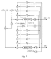
- FIG. 7 illustrates the intermediate IIR parallel TH precoder.
- FIG. 8 illustrates the parallel IIR Tomlinson-Harashima precoder.
- FIG. 9 (Table 1) lists the complexity and critical path for a straightforward L-tap FIR TH precoder (Straightforward-THP), its corresponding 2-parallel design (2-Para-THP) and 3-parallel design (3-Para-THP).
- FIG. 10 (Table 2) lists the complexity and critical path for a straightforward L-th order IIR TH precoder (Straightforward-THP), its corresponding 2-parallel design (2-Para-THP) and 3-parallel design (3-Para-THP).
- TH precoding can be interpreted by using the equivalent form of the TH precoder in FIG. 1( c ).
- a unique compensation signal v(n) which is a multiple of 2M, is added to the transmitted PAM-M signal x(n) such that the output of the precoder t(n) is limited in the interval [ ⁇ M, M). So the effective transmitted data sequence in z-domain is given by
- T ⁇ ( z ) X ⁇ ( z ) + V ⁇ ( z ) H ⁇ ( z ) . EQ . ⁇ ( 2 )
- the received signal is
- An important property of v(n) is that it only has finite levels since v(n) is a multiple of 2M and
- ⁇ (1+ ⁇ i 1 L H
- FIG. 2 shows the straightforward architecture of a 2nd-order TH precoder. It has a critical path consisting of one multiplier, two adders and one modulo device.
- T Critical T Critical
- EQ.(5) The achievable minimum clock period of this architecture is limited by T ⁇ , i.e., we cannot operate the precoder at a speed higher than 1/T ⁇ .
- Classical high-speed design techniques such as retiming and unfolding cannot be used to achieve higher speed since the iteration bound is a fundamental limit. Thus it is important to develop techniques to design a fast TH precoder.
- a TH precoder can be viewed as an IIR filter with an input equal to the sum of the original input to the TH precoder and a finite-level compensation signal.
- the first step to design a parallel TH precoder is to convert the original TH precoder to its equivalent form.
- the classical clustered look-ahead technique is applied to the equivalent form to obtain a parallel IIR filter.
- the parallel IIR filter requires the compensation signal as an explicit input.
- modulo devices are re-introduced to the parallel IIR filter, resulting in an intermediate parallel TH precoder.
- the intermediate parallel precoder still has a very long critical path.
- the precomputation technique is applied. For a 2-parallel design, the resulting final architecture can achieve a speedup of about 2.
- t ( n ) ⁇ h 1 t ( n ⁇ 1) ⁇ h 2 t ( n ⁇ 2)+ x ( n )+ v ( n ), EQ.(8) where v(n) is a compensation signal.
- the 2-stage look-ahead equation of EQ. (8) can be obtained by the clustered look-ahead technique (See, e.g., K. K. Parhi, VLSI Digital Signal Processing Systems Design and Implementation , John Wiley & Son, Inc., New York, 1999):
- t ⁇ ( n ) ( h 2 1 - h 2 ) ⁇ t ⁇ ( n - 2 ) + h 1 ⁇ h 2 ⁇ t ⁇ ( n - 3 ) - h 1 ⁇ x ⁇ ( n - 1 ) - h 1 ⁇ v ⁇ ( n - 1 ) + x ⁇ ( n ) + v ⁇ ( n ) . EQ . ⁇ ( 9 )
- FIG. 3 shows the parallel equivalent IIR filter architecture for the precoder
- FIG. 4 illustrates the intermediate parallel precoders. From FIG. 4 , we can see that there is a long critical path which consists of five additions, two multiplications, and two modulo operations. Compared with the straightforward implementation in FIG. 2 , the improvement is not significant. However, as the compensation signal v(2k+1) only has finite possibilities, we can use precomputation to shorten the critical path, as illustrated in FIG. 5 (In the figure, we assume v(2k+1) has only three levels).
- T Critical 2 T a +T m +T mod +T mux , EQ.(12) where T mux is the computation time of a multiplexer.
- T mux is the computation time of a multiplexer.
- the critical path in the parallel design is only one multiplexing operation longer than that in the straightforward architecture in FIG. 2 .
- the parallel design every time processes two samples and computes two outputs. Thus, it can achieve a speedup of almost 2 since T mux is usually much smaller than T a and T m .
- the present method to design parallel TH precoders can be used to design parallel precoder for order more than 2 and parallelism level more than 2. It can be also used to design parallel IIR TH precoders.
- H ⁇ ( z ) 1 + b 1 ⁇ z - 1 + b 2 ⁇ z - 2 1 + a 1 ⁇ z - 1 + a 2 ⁇ z - 2 .
- the inherent speed is limited by the iteration bound.
- t ⁇ ( n ) - b 1 ⁇ t ⁇ ( n - 1 ) - b 2 ⁇ t ⁇ ( n - 2 ) + x ⁇ ( n ) + a 1 ⁇ x ⁇ ( n - 1 ) + a 2 ⁇ x ⁇ ( n - 2 ) + v ⁇ ( n ) + a 1 ⁇ v ⁇ ( n - 1 ) + a 2 ⁇ v ⁇ ( n - 2 ) .
- t ⁇ ( n ) - b 1 ⁇ t ⁇ ( n - 1 ) - b 2 ⁇ t ⁇ ( n - 2 ) + w ⁇ ( n ) + v ⁇ ( n ) + a 1 ⁇ v ⁇ ( n - 1 ) + a 2 ⁇ v ⁇ ( n - 2 ) .
- t ⁇ ( 2 ⁇ k + 1 ) - b 1 ⁇ t ⁇ ( 2 ⁇ k ) - b 2 ⁇ t ⁇ ( 2 ⁇ k - 1 ) + w ⁇ ( 2 ⁇ k + 1 ) + v ⁇ ( 2 ⁇ k + 1 ) + a 1 ⁇ v ⁇ ( 2 ⁇ k ) + a 2 ⁇ v ⁇ ( 2 ⁇ k - 1 ) , EQ .
- v(2k+1) in EQ. (20) and v(2k+2) in EQ. (21) can be removed by re-introducing modulo operations as follows:
- t ⁇ ( 2 ⁇ k + 1 ) MOD ⁇ ( - b 1 ⁇ t ⁇ ( 2 ⁇ k ) - b 2 ⁇ t ⁇ ( 2 ⁇ k - 1 ) + w ⁇ ( 2 ⁇ k + 1 ) + a 1 ⁇ v ⁇ ( 2 ⁇ k ) + a 2 ⁇ v ⁇ ( 2 ⁇ k - 1 ) , 2 ⁇ M ) , EQ .
- FIG. 7 shows the corresponding architecture for the intermediate parallel precoder described by EQ. (22) and EQ. (23). It has a long critical path
- Table 1 compares the complexity for the straightforward L-tap FIR THP, 2-Para-THP and 3-Para THP.
- the straightforward THP needs L multipliers, 2 adders and one modulo device.
- the 2-Para-THP needs 2L+1 multipliers.
- 2L multipliers are used for loop update for the two-parallel outputs t(2k ⁇ 1) and t(2k).
- this multiplier is the one numbered as 510 .
- One adder is used for the preprocessing of the 2-parallel inputs x(2k+1) and x(2k+2). In FIG. 5 , this adder is the one numbered as 540 . The remaining N adders are used for precomputation. These adders are numbered as 550 , 552 and 556 in FIG. 5 .
- the 2-Para-THP needs 1+N modulo devices. One of them is used for loop update for t(2k ⁇ 1). In FIG. 5 , it is numbered as 560 . The rest are used for loop update for t(2k). In FIG. 5 , they are numbered as 570 , 572 , and 574 .
- the 2-Para THP also needs one W-bit N-to-1 multiplexer (mux) (Assume that the wordlength requirement is W). In FIG. 5 , it corresponds to the part numbered as 580 .
- Table 1 also lists the critical paths for the straightforward THP, 2-Para-THP and 3-Para-THP, which are 2T a +T m +T mod , 2T a +T m +T mod +T mux , and 3T a +T m +T mod +2T mux , respectively.
- Table 2 compares the complexity and the critical path for the straightforward L-th order IIR TH precoder (Straightforward-THP), its corresponding 2-parallel design (2-Para-THP) and 3-parallel design (3-Para-THP).
- a method to design parallel Tomlinson-Harashima precoders based on classical look-ahead and precomputation techniques and properties of Tomlinson-Harashima precoders can be used for high-speed communication applications, such as 10 Gigabit Ethernet over copper.
Abstract
Description
where LH is the channel memory length. We assume that the model is known at the transmitter side. We also assume that the transmitted symbols are PAM-M symbols, where the symbol set is {±1, ±3, . . . , ±(M−1)}. To remove inter-symbol interference (ISI), we can use zero-forcing pre-equalization, which basically implements the inverse of the channel transfer function at the transmitter side, as illustrated in
The received signal is
and X(z) can be recovered from R(z) by performing a modulo operation. An important property of v(n) is that it only has finite levels since v(n) is a multiple of 2M and |v(n)|≦(1+Σi=1 L
T Critical=2T a +T m +T mod, EQ.(4)
where Ta, Tm and Tmod denote the computation times of an addition, a multiplication and a modulo operation, respectively (Note: Tmod=0 when M is a power of 2). From the figure, we can see that the iteration bound, T∞ (For the definition of iteration bound, please see K. K. Parhi, VLSI Digital Signal Processing Systems Design and Implementation, John Wiley & Son, Inc., New York, 1999), of the architecture is also equal to TCritical, i.e.,
T ∞ =T Critical=2T a +T m +T mod. EQ.(5)
The achievable minimum clock period of this architecture is limited by T∞, i.e., we cannot operate the precoder at a speed higher than 1/T∞. Classical high-speed design techniques such as retiming and unfolding cannot be used to achieve higher speed since the iteration bound is a fundamental limit. Thus it is important to develop techniques to design a fast TH precoder.
H(z)=1+h 1 z −1 +h 2 z −2. EQ.(6)
The corresponding FIR TH precoder can be described as
t(n)=MOD(−h 1 t(n−1)−h 2 t(n−2)+x(n),2M), EQ.(7)
where MOD(*, 2M) is a modulo operation by 2M.
t(n)=−h 1 t(n−1)−h 2 t(n−2)+x(n)+v(n), EQ.(8)
where v(n) is a compensation signal. The 2-stage look-ahead equation of EQ. (8) can be obtained by the clustered look-ahead technique (See, e.g., K. K. Parhi, VLSI Digital Signal Processing Systems Design and Implementation, John Wiley & Son, Inc., New York, 1999):
v(2k+1) and v(2k+2) can be removed as explicit inputs to the above parallel IIR filter by re-introducing a modulo operation as follows, resulting in an intermediate parallel TH precoder:
T Critical=2T a +T m +T mod +T mux, EQ.(12)
where Tmux is the computation time of a multiplexer. The critical path in the parallel design is only one multiplexing operation longer than that in the straightforward architecture in
The corresponding TH precoder can be described as
t(n)=MOD(x(n)−f(n),2M), EQ.(14)
where f(n) is the inverse z-transform of (H(z)−1)T(z). Its straightforward architecture is shown in
T Critical=4T a+2T m +T mod, EQ.(15)
and the iteration bound, T∞, of the architecture is
T ∞=3T a +T m +T mod. EQ.(16)
The inherent speed is limited by the iteration bound.
The corresponding parallel IIR system can be obtained by substituting n=2k+1 and n=2k+2 into equation EQ. (18) and EQ. (19), respectively, and is described by:
T critical=4T a +T m+2T mod +T mux. EQ.(24)
The parallel design every time processes two samples and computes two outputs, so we can achieve a sample period
T Sample=2T a +T m/2+T mod +T mux/2. EQ.(25)
The computation of a multiplier is usually much longer than those of an adder and a multiplexer, and hence speedup is achieved.
| TABLE 1 | ||||
| Straightforward- | ||||
| THP | 2-Para-THP | 3- | ||
| Multipliers | L |
| 2L + 1 | 3L + 3 | |||
| | L | 2L + |
3L + 2N + 2N2 + 1 | |
| Modulo | 1 | N + 1 | 1 + N + N2 | |
| Devices | ||||
| Multiplexers | None | One W-bit | One W-bit N-to-1 mux | |
| N-to-1 mux | One W-bit N2-to-1 mux | |||
| Critical Path | 2Ta + Tm + | 2Ta + Tm + | 3Ta + Tm + Tmod + 2Tmux | |
| Tmod | Tmod + Tmux | |||
| TABLE 2 | ||||
| Straightforward- | ||||
| THP | 2-Para-THP | 3- | ||
| Multipliers |
| 2L |
| 6L + 1 | 9L + 3 | |||
| | 2L | 6L + |
9L + 2N + 2N2 + 1 | |
| Modulo | 1 | N + 1 | 1 + N + N2 | |
| Devices | ||||
| Multiplexers | None | One W-bit | One W-bit N-to-1 mux | |
| N-to-1 mux | One Wv-bit N-to-1 mux | |||
| One Wv-bit | One W-bit N2-to-1 mux | |||
| N-to-1 mux | One Wv-bit N2-to-1 mux | |||
| Critical Path | 5Ta + 2Tm + | 4Ta + Tm + | 6Ta + Tm + Tmod + 2Tmux | |
| Tmod | Tmod + Tmux | |||
Claims (6)
Priority Applications (1)
| Application Number | Priority Date | Filing Date | Title |
|---|---|---|---|
| US11/181,347 US7693233B2 (en) | 2005-07-13 | 2005-07-13 | Parallel Tomlinson-Harashima precoders |
Applications Claiming Priority (1)
| Application Number | Priority Date | Filing Date | Title |
|---|---|---|---|
| US11/181,347 US7693233B2 (en) | 2005-07-13 | 2005-07-13 | Parallel Tomlinson-Harashima precoders |
Publications (2)
| Publication Number | Publication Date |
|---|---|
| US20070014380A1 US20070014380A1 (en) | 2007-01-18 |
| US7693233B2 true US7693233B2 (en) | 2010-04-06 |
Family
ID=37661648
Family Applications (1)
| Application Number | Title | Priority Date | Filing Date |
|---|---|---|---|
| US11/181,347 Active 2027-09-15 US7693233B2 (en) | 2005-07-13 | 2005-07-13 | Parallel Tomlinson-Harashima precoders |
Country Status (1)
| Country | Link |
|---|---|
| US (1) | US7693233B2 (en) |
Cited By (1)
| Publication number | Priority date | Publication date | Assignee | Title |
|---|---|---|---|---|
| US8428110B2 (en) | 2011-03-25 | 2013-04-23 | International Business Machines Corporation | Pipelining and sub-rate operation for memory links |
Families Citing this family (5)
| Publication number | Priority date | Publication date | Assignee | Title |
|---|---|---|---|---|
| US7769099B2 (en) * | 2004-09-13 | 2010-08-03 | Leanics Corporation | High-speed precoders for communication systems |
| US9031178B2 (en) * | 2013-08-27 | 2015-05-12 | Broadcom | Generalized transmit pre-coding for optical and backplane channels |
| DE102014222511A1 (en) | 2014-11-04 | 2016-05-04 | Fraunhofer-Gesellschaft zur Förderung der angewandten Forschung e.V. | Transmitting means for transmitting an output signal, receiving means for receiving an output signal and method for transmitting or receiving the same |
| WO2016113201A1 (en) * | 2015-01-16 | 2016-07-21 | Giva Audiovisual Technologies Bvba | Audio, video and light control system encapsulated in a single housing |
| US9521026B1 (en) | 2015-06-07 | 2016-12-13 | Valens Semiconductor Ltd. | Tomlinson-harashima precoding with non-overlapping dynamic modulation coding subsets |
Citations (4)
| Publication number | Priority date | Publication date | Assignee | Title |
|---|---|---|---|---|
| US20020122503A1 (en) * | 2001-03-01 | 2002-09-05 | Agazzi Oscar E. | Digital signal processing based de-serializer |
| US20030086515A1 (en) * | 1997-07-31 | 2003-05-08 | Francois Trans | Channel adaptive equalization precoding system and method |
| US20060056521A1 (en) | 2004-09-13 | 2006-03-16 | Regents Of The University Of Minnesota | High-speed precoders for communication systems |
| US20070014345A1 (en) | 2005-07-13 | 2007-01-18 | Leanics Corporation | Low complexity Tomlinson-Harashima precoders |
-
2005
- 2005-07-13 US US11/181,347 patent/US7693233B2/en active Active
Patent Citations (4)
| Publication number | Priority date | Publication date | Assignee | Title |
|---|---|---|---|---|
| US20030086515A1 (en) * | 1997-07-31 | 2003-05-08 | Francois Trans | Channel adaptive equalization precoding system and method |
| US20020122503A1 (en) * | 2001-03-01 | 2002-09-05 | Agazzi Oscar E. | Digital signal processing based de-serializer |
| US20060056521A1 (en) | 2004-09-13 | 2006-03-16 | Regents Of The University Of Minnesota | High-speed precoders for communication systems |
| US20070014345A1 (en) | 2005-07-13 | 2007-01-18 | Leanics Corporation | Low complexity Tomlinson-Harashima precoders |
Non-Patent Citations (10)
| Title |
|---|
| Gu, Yongru et al., "Pipelining Tomlinson-Harashima Precoders", IEEE International Symposijm on Circuits & Systems; May 23-26, 2005, pp. 408-411. |
| Gu, Yongru et al; Pipelining Tomlinson-Harashima Precoders; IEEE International Symposium on Circuits & Systems; May 23-26, 2005; pp. 408-411. |
| Harashima, Hiroshi et al., Matched-Transmission Technique For Channels IEEE Transactions on Communications (Aug. 1972) 774-780. |
| Harashima, Hiroshi et al; Matched-Transmission Technique for Channels with Intersymbol Interference; IEEE Transactions on Communications; Aug. 1972; pp. 774-780. |
| Parhi et al.; Pipeline Interleaving and parallelism in recursive digital filters. I. Pipelining using a scattered look-ahead decomposition; IEEE Transactions on Acoustics, Speech and Signal Processing; Jul. 1989; pp. 1099-1117. |
| Parhi Keshab K.; Pipelining in algorithms with quantizer loops; IEEE Transactions on Circuits & Systems; Jul. 1991; pp. 745-754. |
| Parhi, Keshab K., "Pipelining in Algorithms with Quantizer Loops", IEEE Transactions on Circuit and Systems (Jul. 1991), 745-754. |
| Parhi, Keshab K., et al., Pipeline Interleaving and Parallelism In Recursive IEEE Transactions on Acoustics, Speech & Signal Processing (Jul. 1989), 1099-1117. |
| Wesel, Richard D., et al., Achievable Rates for Tomlinson-Harashima Preco IEEE Transactions on Information Theory (Mar. 1998), 824-831. |
| Wesel, Richard et al; Achievable Rates for Tomlinson-Harashima Precorders; IEEE Transactions on Information Theory; Mar. 1998; pp. 824-831. |
Cited By (2)
| Publication number | Priority date | Publication date | Assignee | Title |
|---|---|---|---|---|
| US8428110B2 (en) | 2011-03-25 | 2013-04-23 | International Business Machines Corporation | Pipelining and sub-rate operation for memory links |
| US8520724B2 (en) | 2011-03-25 | 2013-08-27 | International Business Machines Corporation | Pipelining and sub-rate operation for memory links |
Also Published As
| Publication number | Publication date |
|---|---|
| US20070014380A1 (en) | 2007-01-18 |
Similar Documents
| Publication | Publication Date | Title |
|---|---|---|
| US7130366B2 (en) | Compensation circuit and method for reducing intersymbol interference products caused by signal transmission via dispersive media | |
| US9935800B1 (en) | Reduced complexity precomputation for decision feedback equalizer | |
| US6192072B1 (en) | Parallel processing decision-feedback equalizer (DFE) with look-ahead processing | |
| US20140056346A1 (en) | High-speed parallel decision feedback equalizer | |
| US7693233B2 (en) | Parallel Tomlinson-Harashima precoders | |
| US10720994B2 (en) | PAM-4 transmitter precoder for 1+0.5D PR channels | |
| CN104348771A (en) | Method and apparatus for encoding signals | |
| US7769099B2 (en) | High-speed precoders for communication systems | |
| US20070014345A1 (en) | Low complexity Tomlinson-Harashima precoders | |
| US8009823B2 (en) | System and method for low-power echo and NEXT cancellers | |
| Newhall et al. | A technique for finding approximate inverse systems and its applications to equalization | |
| EP0800735B1 (en) | Adaptive equalization for priv transmission systems | |
| US8498343B2 (en) | System for MIMO equalization of multi-channel transceivers with precoding | |
| Emeretlis et al. | High-performance FPGA implementations of volterra DFEs for optical fiber systems | |
| Klein et al. | MMSE decision feedback equalization of pulse position modulated signals | |
| Nanou et al. | 40 Gb/s FPGA implementation of a reduced complexity volterra DFE for DQPSK optical links | |
| Gu et al. | Pipelining Tomlinson-Harashima precoders | |
| EP3857712B1 (en) | Cascadable filter architecture | |
| Gu et al. | Design of Parallel Tomlinson–Harashima Precoders | |
| US11736144B2 (en) | Decomposed real-imaginary equalizer | |
| US11347476B2 (en) | Digital filtering using combined approximate summation of partial products | |
| CN102347921A (en) | Receiver and method for carrying out equalization processing on receiving signal | |
| Cherubini | Analysis of the convergence behavior of adaptive distributed-arithmetic echo cancellers | |
| Klein et al. | MMSE decision feedback equalization of orthogonal multipulse modulated signals | |
| Emeretlis et al. | Efficient FPGA implementations of volterra DFES for optical systems |
Legal Events
| Date | Code | Title | Description |
|---|---|---|---|
| AS | Assignment |
Owner name: LEANICS CORPORATION,MINNESOTA Free format text: ASSIGNMENT OF ASSIGNORS INTEREST;ASSIGNORS:GU, YONGRU;PARHI, KESHAB K.;REEL/FRAME:016796/0297 Effective date: 20050713 Owner name: LEANICS CORPORATION, MINNESOTA Free format text: ASSIGNMENT OF ASSIGNORS INTEREST;ASSIGNORS:GU, YONGRU;PARHI, KESHAB K.;REEL/FRAME:016796/0297 Effective date: 20050713 |
|
| STCF | Information on status: patent grant |
Free format text: PATENTED CASE |
|
| FPAY | Fee payment |
Year of fee payment: 4 |
|
| AS | Assignment |
Owner name: PARHI, KESHAB K, MINNESOTA Free format text: NUNC PRO TUNC ASSIGNMENT;ASSIGNOR:LEANICS CORPORATION;REEL/FRAME:037512/0032 Effective date: 20160118 |
|
| MAFP | Maintenance fee payment |
Free format text: PAYMENT OF MAINTENANCE FEE, 8TH YR, SMALL ENTITY (ORIGINAL EVENT CODE: M2552) Year of fee payment: 8 |
|
| FEPP | Fee payment procedure |
Free format text: MAINTENANCE FEE REMINDER MAILED (ORIGINAL EVENT CODE: REM.); ENTITY STATUS OF PATENT OWNER: SMALL ENTITY |
|
| FEPP | Fee payment procedure |
Free format text: 11.5 YR SURCHARGE- LATE PMT W/IN 6 MO, SMALL ENTITY (ORIGINAL EVENT CODE: M2556); ENTITY STATUS OF PATENT OWNER: SMALL ENTITY |
|
| MAFP | Maintenance fee payment |
Free format text: PAYMENT OF MAINTENANCE FEE, 12TH YR, SMALL ENTITY (ORIGINAL EVENT CODE: M2553); ENTITY STATUS OF PATENT OWNER: SMALL ENTITY Year of fee payment: 12 |