US7733060B2 - Charging IC, charging apparatus and electronic device - Google Patents
Charging IC, charging apparatus and electronic device Download PDFInfo
- Publication number
- US7733060B2 US7733060B2 US11/260,258 US26025805A US7733060B2 US 7733060 B2 US7733060 B2 US 7733060B2 US 26025805 A US26025805 A US 26025805A US 7733060 B2 US7733060 B2 US 7733060B2
- Authority
- US
- United States
- Prior art keywords
- charging
- power source
- constant
- current
- voltage
- Prior art date
- Legal status (The legal status is an assumption and is not a legal conclusion. Google has not performed a legal analysis and makes no representation as to the accuracy of the status listed.)
- Expired - Fee Related, expires
Links
Images


Classifications
-
- H—ELECTRICITY
- H02—GENERATION; CONVERSION OR DISTRIBUTION OF ELECTRIC POWER
- H02J—CIRCUIT ARRANGEMENTS OR SYSTEMS FOR SUPPLYING OR DISTRIBUTING ELECTRIC POWER; SYSTEMS FOR STORING ELECTRIC ENERGY
- H02J7/00—Circuit arrangements for charging or depolarising batteries or for supplying loads from batteries
- H02J7/02—Circuit arrangements for charging or depolarising batteries or for supplying loads from batteries for charging batteries from ac mains by converters
-
- H—ELECTRICITY
- H02—GENERATION; CONVERSION OR DISTRIBUTION OF ELECTRIC POWER
- H02J—CIRCUIT ARRANGEMENTS OR SYSTEMS FOR SUPPLYING OR DISTRIBUTING ELECTRIC POWER; SYSTEMS FOR STORING ELECTRIC ENERGY
- H02J5/00—Circuit arrangements for transfer of electric power between ac networks and dc networks
-
- H—ELECTRICITY
- H02—GENERATION; CONVERSION OR DISTRIBUTION OF ELECTRIC POWER
- H02J—CIRCUIT ARRANGEMENTS OR SYSTEMS FOR SUPPLYING OR DISTRIBUTING ELECTRIC POWER; SYSTEMS FOR STORING ELECTRIC ENERGY
- H02J7/00—Circuit arrangements for charging or depolarising batteries or for supplying loads from batteries
- H02J7/0029—Circuit arrangements for charging or depolarising batteries or for supplying loads from batteries with safety or protection devices or circuits
- H02J7/00309—Overheat or overtemperature protection
-
- H—ELECTRICITY
- H02—GENERATION; CONVERSION OR DISTRIBUTION OF ELECTRIC POWER
- H02J—CIRCUIT ARRANGEMENTS OR SYSTEMS FOR SUPPLYING OR DISTRIBUTING ELECTRIC POWER; SYSTEMS FOR STORING ELECTRIC ENERGY
- H02J7/00—Circuit arrangements for charging or depolarising batteries or for supplying loads from batteries
- H02J7/0029—Circuit arrangements for charging or depolarising batteries or for supplying loads from batteries with safety or protection devices or circuits
- H02J7/0031—Circuit arrangements for charging or depolarising batteries or for supplying loads from batteries with safety or protection devices or circuits using battery or load disconnect circuits
- H02J7/0032—Circuit arrangements for charging or depolarising batteries or for supplying loads from batteries with safety or protection devices or circuits using battery or load disconnect circuits disconnection of loads if battery is not under charge, e.g. in vehicle if engine is not running
-
- H—ELECTRICITY
- H02—GENERATION; CONVERSION OR DISTRIBUTION OF ELECTRIC POWER
- H02J—CIRCUIT ARRANGEMENTS OR SYSTEMS FOR SUPPLYING OR DISTRIBUTING ELECTRIC POWER; SYSTEMS FOR STORING ELECTRIC ENERGY
- H02J7/00—Circuit arrangements for charging or depolarising batteries or for supplying loads from batteries
- H02J7/007—Regulation of charging or discharging current or voltage
- H02J7/00712—Regulation of charging or discharging current or voltage the cycle being controlled or terminated in response to electric parameters
- H02J7/007182—Regulation of charging or discharging current or voltage the cycle being controlled or terminated in response to electric parameters in response to battery voltage
Definitions
- the present invention relates generally to a charging apparatus of rechargeable batteries built into electronic devices such as mobile terminals, and, more particularly, to a charging IC (Integrated Circuit), charging apparatus and an electronic device using as a charging source of the rechargeable batteries an external power source such as an AC (Alternating Current) adaptor or a USB (Universal Serial Bus) host such as a personal computer connected with a USB cable.
- a charging IC Integrated Circuit
- AC Alternating Current
- USB Universal Serial Bus
- FIG. 1 is a circuit diagram of a charging apparatus using a PMOS (P-channel Metal Oxide Semiconductor) transistor for charging control
- FIG. 2 is a flowchart of the charging control
- FIG. 3 is a diagram showing a charging operation.
- PMOS P-channel Metal Oxide Semiconductor
- This charging apparatus 2 is configured to use an AC adaptor 8 as a charging source to charge a rechargeable battery 6 built into an electronic device 3 along with an apparatus load 4 .
- the charging apparatus 2 is provided with a charging IC 10 , and the charging IC 10 integrates circuit units such as a charging control unit which can be integrated into an IC.
- a charging path 11 is formed for passing a charging current between the AC adaptor 8 and the rechargeable battery 6 ; the charging path 11 is equipped with a PMOS transistor (Tr) 12 as a charging control element; and the PMOSTr 12 is connected serially with a backflow prevention diode 14 and a sense resistor 16 .
- Pr PMOS transistor
- the sense resistor 16 converts the charging current flowing through the charging path 11 to a voltage to be detected and the detected current is applied to the charging IC 10 as control information. Control output obtained in the charging IC 10 is applied to a gate of the PMOSTr 12 to execute charging-current control or constant-voltage control.
- step S 1 In the charging of the rechargeable battery 6 with the charging apparatus 2 , as shown in FIG. 2 , when the AC adaptor 8 is detected as the charging source, the output voltage of the AC adaptor 8 is detected, and then, a battery status check is performed for a battery temperature and a battery voltage which indicate a battery status (step S 1 ). If the result of the battery status check is normal, a charging operation is started. At the start of the charging operation, first constant-current charging CC 1 is performed as fast charging (step S 2 ), except the case that a battery voltage is too low (an over-discharge state), and the battery voltage is raised by the first constant-current charging CC 1 to a start voltage of constant-voltage charging (step S 3 ).
- step S 4 second constant-current charging CC 2 is performed (step S 4 ), and when full charging is achieved through constant-voltage charging (step S 5 ), the charging is completed.
- a constant current Icc 1 of CC 1 a constant current Icc 2 of CC 2 is in a relationship of Icc 2 ⁇ Icc 1 .
- FIG. 3 is a diagram showing transitions of charging forms, charging currents and charging voltages.
- the output voltage of the AC adaptor 8 is set higher than the charging completion voltage, and maximum heat generation happens at the point of time when the second constant-current charging is switched to the constant-voltage charging.
- FIG. 4 is a diagram showing transitions of the heat generation amount in each portion during the charging operation.
- the heat generation of the diode 14 is largest and accounts for one-half of the total heat generation amount.
- the total heat generation amount is larger than the constant-current charging CC 1 region (t 1 to t 2 )
- the heat generation amounts of the diode 14 and sense resistor 16 is smaller than the CC 1 region (t 1 to t 2 ) while the heat generation amounts of the PMOSTr 12 accounts for two third of the total heat generation amount.
- the heat generation amount is reduced dependently on reduction of the charging current.
- the heat generation amount of the PMOSTr 12 is largest.
- PMOSTr 12 when making the shift to the constant-current charging CC 2 , PMOSTr 12 generates heat depending on electric power applying a voltage. Such heat generation leads to energy loss.
- a start voltage of the constant-current charging CC 1 is set to, for example, about 3 [V]
- the charging current Ic is dependent on the output of the AC adaptor 8 because the drooping characteristic of the AC adaptor 8 is used. Therefore, in the CC 1 region, the charging current Ic is on the order of 670 [mA].
- Voa Vb +(external part resistance [ ⁇ ] ⁇ Ic ) (1)
- the external part generates heat depending on this acceptable loss.
- a constant current Icc 2 in the CC 2 region is set to, for example, 350 [mA]
- the output voltage Voa is about 5.4 [V]
- the loss due to the external part is about 456 [mW]
- about 318 [mW] is lost by the heat generation of the PMOSTr 12 .
- constant-voltage control is performed such that the battery voltage Vb will be 4.2 [V], and as the rechargeable battery 6 approaches full charge, the charging current Ic is reduced.
- the heat generation is lower than the CC 2 .
- the charging is completed and the charging operation is terminated if the charging current Ic reduced to on the order of 50 [mA].
- a charging apparatus 2 in FIG. 5 is a case that a PMOSTr 18 is used as a backflow prevention element, instead of the diode 14 described above.
- the same symbols are added to the same portions as FIG. 1 .
- the PMOSTr 18 is operated by a control signal applied from the charging IC 10 to a gate to regulate the direction of the charging current Ic passing through the charging path 11 .
- the heat generation amount of the charging apparatus 2 shown in FIG. 5 in the first constant-current charging CC 1 region (t 1 to t 2 ) the heat generation of the sense resistor 16 is largest and accounts for one-half of the total heat generation amount.
- the total heat generation amount in the second constant-current charging CC 2 region (t 2 to t 3 ) is about twice larger than the constant-current charging CC 1 region (t 1 to t 2 ), and the heat generation amounts of the PMOSTr 18 and the sense resistor 16 are dropped to on the order of one-fifth of the total heat generation amount, while the heat generation amount of the PMOSTr 12 accounts for four-fifth of the total heat generation amount.
- the heat generation amount is reduced dependently on reduction of the charging current.
- PMOSTr 12 when making the shift to the constant-current charging CC 2 , PMOSTr 12 generates heat depending on electric power applying a voltage. As described above, such heat generation leads to energy loss.
- a switching power source 20 is disposed with in the charging IC 10 , and the output of the switching power source 20 is picked up after passing though a filter circuit 26 consisting of an inductor 22 and capacitor 24 and is supplied to the rechargeable battery 6 through the charging path 11 .
- a filter circuit 26 consisting of an inductor 22 and capacitor 24 and is supplied to the rechargeable battery 6 through the charging path 11 .
- the PMOSTr 18 for backflow prevention is disposed in the charging path 11 , the PMOSTr 18 may be omitted.
- the AC adaptor 8 is used as a charging source, and the output of the AC adaptor 8 is applied to the switching power source 20 to generate constant currents Icc 1 , Icc 2 and a constant voltage Vc which achieve a first constant-current charging CC 1 , second constant-current charging CC 2 and constant-voltage charging CV. Therefore, in regard to the heat generation amount of the charging apparatus 2 ( FIG. 7 ), as shown in FIG. 8 , in the first constant-current charging CC 1 region (t 1 to t 2 ) the heat generation of the switching power source 20 is largest and accounts for one-half of the total heat generation amount.
- the total heat generation amount in the constant-current charging CC 2 region (t 2 to t 3 ) is reduced to on the order of one-half of the constant-current charging CC 1 region (t 1 to t 2 ); the heat generation amount of the switching power source 20 also comes down to on the order of one-half of the total heat generation amount as compared to the region of the constant-current charging CC 1 (t 1 to t 2 ); and in the constant-voltage charging CV region (t 3 to t 4 ), the heat generation amount is reduced dependently on reduction of the charging current.
- device chassis are miniaturized and thinned as well as equipped batteries are planned to be large capacity, and it is requested to constrain the heat generation when the devices are operated for phone calls and the like during the charging operation.
- An object of the present invention relates to charging of rechargeable batteries built into electronic devices and is to constrain heat generation during the charging.
- Another object of the present invention relates to charging of rechargeable batteries using external devices such as Ac adaptors or USB hosts and is to plan to promote the efficiency of the charging.
- a charging IC used for charging a rechargeable battery built into an electronic device, comprising a power source unit which can be fed with power from an external power source with a drooping characteristic to pick up a constant current; and a control unit which applies a first constant current from the external power source to the rechargeable battery through a circuit element disposed on a charging path of the rechargeable battery, the control unit applying a second constant current smaller than the first constant current from the power source unit to the rechargeable battery after the rechargeable battery is charged with the first constant current to a predetermined voltage.
- the rechargeable battery is charged by applying the first constant current to the rechargeable battery from the external power source, such as an AC adaptor, with the drooping characteristic, and after the rechargeable battery is charged to the predetermined voltage, the rechargeable battery can be charged by applying the second constant current from the power source unit built into the charging IC to the rechargeable battery.
- the rechargeable battery can be charged by applying the second constant current from the power source unit built into the charging IC to the rechargeable battery.
- a current value is large for the first constant current supplied to the rechargeable battery from the external power source with the drooping characteristic, and the second constant current supplied from the power source unit built into the charging IC is smaller than the first constant current.
- the heat generation amount thereof is small, since the current value of the second constant current is smaller than that of the first constant current.
- the second constant current is directly supplied from the power source unit to the rechargeable battery and the circuit elements are not involved, the circuit elements do not generate heat when the second constant current is supplied.
- the first constant current is applied through the circuit elements which generate heat, the heat generation amount thereof is small.
- the heat generation amount is considerably reduced. Therefore, the heating or heat generation amount is constrained in the electronic device equipped with the charging IC.
- the heat generation of the external power source occurs outside of the electronic device which is the device equipped with the charging IC and, therefore, is irrelevant to the heat generation of the electronic device.
- the power source unit is preferably fed with power from an external device connected to the electronic device to output the constant current or a constant voltage
- the control unit is preferably configured to apply a constant voltage from the power source unit to the rechargeable battery to switch over to constant-voltage charging after the charging with the second constant current. According to such a configuration, the rechargeable battery is charged to the predetermined voltage by the constant-voltage charging.
- the external power source may be, but not exclusively, an AC adaptor converting an alternate current received from an alternate-current power source into a direct current with a predetermined voltage to be picked up.
- the power source unit is preferably, but not exclusively, a switching power source converting direct-current input to direct-current output.
- a charging IC used for charging a rechargeable battery built into an electronic device, comprising a power source unit which is fed with power from an external device connected to the electronic device to output constant currents; and a control unit which switches constant currents applied from the power source unit to the rechargeable battery based on power-feeding information provided from the external device.
- the constant current is obtained in the power source unit due to the power feeding from the external device and the rechargeable battery is charged by this constant current, if the power feeding capacity is high, based on the power feeding information provided from the external device, switch-over to the power source unit is performed, and the rechargeable battery is charged with the switched larger constant-current.
- the rechargeable battery is charged by the low-power power source unit or the power source unit, the heat generation amount of the charging IC is constrained and, in turn, the heating or heat generation amount is constrained in the electronic device equipped with the charging IC.
- the power source unit may be fed with power from an external device connected to the electronic device and comprise of a first power source circuit outputting a constant current and a second power source circuit outputting a constant current smaller than the first power source circuit; and the control unit may be configured to apply the constant current from the second power source circuit to the rechargeable battery and switch output from the second power source circuit to the first power source circuit based on power-feeding information provided from the external device to apply the constant current to the rechargeable battery.
- the external device is preferably, but not exclusively, an electronic device connected by a USB cable.
- a charging apparatus used for charging a rechargeable battery built into an electronic device, comprising: a power source unit which is fed with power from an external power source having a drooping characteristic or an external device connected to the electronic device; a switch which is disposed between the power source unit and the external power source or the external device to switch connection of the external power source or the external device with the power source unit; a circuit element disposed on a charging path of the rechargeable battery; and a control unit, if the external power source is connected to the power source unit, applying a first constant current from the external power source to the rechargeable battery through the circuit element and applying a second constant current smaller than the first constant current from the power source unit to the rechargeable battery after the rechargeable battery is charged with the first constant current to a predetermined voltage, the control unit, if the external device is connected to the power source unit, switching a constant current in accordance with a power-feeding capability of the external device based on power
- the switch is used for switching the power supply, charging is controlled responding to the switching.
- the rechargeable battery is charged by applying the first constant current to the rechargeable battery from the external power source, such as an AC adaptor, with the drooping characteristic, and after the rechargeable battery is charged to the predetermined voltage, the rechargeable battery can be charged by applying the second constant current from the power source unit.
- the switch may be, but not exclusively, configured to select either the external power source or the external device or select the external power source to connect to the power source unit, if both of the external power source and the external device are connected.
- control unit is preferably, but not exclusively, configured to select either the external power source or the external device with the switch to connect to the power source unit, if both of the external power source and the external device are connected.
- the power source unit may be fed with power from an external device connected to the electronic device to output a current or voltage in accordance with a power-feeding capability of the electronic device, and the control unit may be configured to switch over to constant-voltage charging after the charging with the second constant current.
- Heat generation is suppressed in the charging IC, and heating and a heat generation amount are suppressed in a charging apparatus or an electronic device installed the charging IC.
- heat radiation measures can be made lighter.
- heat radiation measures of a mobile terminal can be made lighter, which facilitates to make the product thinner.
- FIG. 1 is a diagram showing a charging apparatus of a rechargeable battery built into an electronic device
- FIG. 2 is a flowchart showing a charging operation
- FIG. 3 is a diagram showing a relationship among a battery voltage, a voltage supplied to a battery and a charging current
- FIG. 4 is a diagram showing a relationship between charging and a heat generation amount
- FIG. 5 is a diagram showing another charging apparatus
- FIG. 6 is a diagram showing a relationship between charging and a heat generation amount
- FIG. 7 is a diagram showing another charging apparatus
- FIG. 8 is a diagram showing a relationship between charging and a heat generation amount
- FIG. 9 is a diagram showing an outline of a charging IC, a charging apparatus and an electronic device according to a first embodiment
- FIG. 10 is a diagram showing a configuration example of the charging IC, charging apparatus and electronic device according to the first embodiment
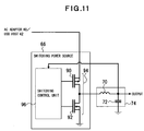
- FIG. 11 is a diagram showing a configuration example of a switching power source
- FIG. 12 is a flowchart showing a charging control method according to the first embodiment
- FIG. 13 is a circuit diagram showing a charging operation in the case of using an AC adaptor
- FIG. 14 is a circuit diagram showing a charging operation in the case of using an AC adaptor
- FIG. 15 is a circuit diagram showing a charging operation in the case of using an AC adaptor
- FIG. 16 is a circuit diagram showing a charging operation in the case of using a USB host
- FIG. 17 is a circuit diagram showing a charging operation in the case of using a USB host
- FIG. 18 is a circuit diagram showing a charging operation in the case of using a USB host
- FIG. 19 is a diagram showing a charging operation in the case of using an AC adaptor
- FIG. 20 is a diagram showing a heat generation amount in the case of using an AC adaptor
- FIG. 21 is a diagram showing a charging operation in the case of using a USB host
- FIG. 22 is a diagram showing a heat generation amount in the case of using a USB host
- FIG. 23 is a diagram showing a charging operation in the case of using a USB host
- FIG. 24 is a diagram showing a heat generation amount in the case of using a USB host
- FIG. 25 is a flowchart showing a charging control method according to a second embodiment
- FIG. 26 is a diagram showing a charging apparatus according to a third embodiment
- FIG. 27 is a diagram showing a charging apparatus according to a fourth embodiment.
- FIG. 28 is a diagram showing a charging apparatus and an electronic device according to a fifth embodiment
- FIG. 29 is a diagram showing a cellular phone according to a sixth embodiment.
- FIG. 30 is a diagram showing a cellular phone connected to an AC adaptor
- FIG. 31 is a diagram showing a cellular phone placed on a charging platform
- FIG. 32 is a diagram showing a cellular phone connected to a PC
- FIG. 33 is a diagram showing a cellular phone connected to a PC and placed on a charging platform
- FIG. 34 is a diagram showing charging of a PDA according to a seventh embodiment
- FIG. 35 is a diagram showing an operation property of an example of the present invention.
- FIG. 36 is a diagram showing an operation property of an example of the present invention.
- FIG. 37 is a diagram showing an operation property of a comparative example 1
- FIG. 38 is a diagram showing an operation property of a comparative example 1
- FIG. 39 is a diagram showing an operation property of a comparative example 2.
- FIG. 40 is a diagram showing an operation property of a comparative example 2.
- FIG. 9 is a diagram showing an outline of a charging IC, a charging apparatus and an electronic device according to the first embodiment.
- An electronic device 30 is equipped with a rechargeable battery 34 feeding power to an apparatus load 32 as well as a charging apparatus 36 charging the rechargeable battery 34 , and the charging apparatus 36 is equipped with a charging IC 38 .
- the electronic device 30 is a mobile terminal apparatus such as a cellular phone and a device such as an electronic camera and may be any device, as long as a rechargeable battery is equipped or used.
- the apparatus load 32 is a load consuming electric energy supplied from the rechargeable battery 34 .
- the rechargeable battery 34 is a secondary battery, such as a lithium-ion battery, which can discharge and can be charged.
- the charging IC 38 integrates circuit units such as a power source unit and control unit which can be integrated in the charging apparatus, and is used for controlling the charging of the rechargeable battery 34 and switching the charging patterns.
- an AC adaptor 40 is used as an external power source and, for example, a USB (Universal Serial Bus) host 42 is used as an external device with a power-feeding capability.
- the AC adaptor 40 is a power supply apparatus constituted by an AC-DC converter connected to, for example, an outlet of a commercial alternating-current power supply AC to convert the commercial alternating current into a direct current (DC) with a desired voltage.
- the USB host 42 is, for example, an electronic device with a power-feeding capability, such as a personal computer, and feeds power through a USB cable 44 . Devices other than the USB host 42 may be used as the external device.
- the charging apparatus 36 is connected to the AC adaptor 40 with an adaptor connector 46 which is a connection unit as well as connected to the USB cable 44 of the USB host 42 with a USB connector 48 which is a connection unit.
- a switch 50 is used for selecting a charging source and, for example, if both of the AC adaptor 40 and the USB host 42 are connected, the switch 50 is used for switch-over to give priority to, for example, the connection of the AC adaptor 40 as one or the other of the devices or as a device with higher power-feeding capability.
- a charging path 52 is formed between the switch 50 and the rechargeable battery 34 .
- the charging path 11 is equipped with a PMOSTr 54 as a charging control circuit element, a PMOSTr 56 as a backflow prevention circuit element and a sense resistor 58 as a current detection element, which constitute a series circuit.
- the PMOSTr 54 is controlled by the charging IC 38 and applies a first constant current Icc 1 to the rechargeable battery 34 through the charging path 52 .
- the PMOSTr 56 is controlled by the charging IC 38 and prevents currents from flowing back from the rechargeable battery 34 through the charging path 52 to the AC adaptor 40 or USB host 42 .
- the sense resistor 58 converts the charging current flowing through the charging path 52 to a voltage to be detected and the detected voltage is applied to the charging IC 38 as control information.
- the charging IC 38 is provided with an adaptor detection terminal 60 and a USB detection terminal 62 as well as a control unit 64 , a switching power source 66 and a linear voltage regulator 68 as a built-in power source unit and others.
- the switching power source 66 is, for example, a DC-DC converter generating a constant-current output or constant-voltage output and constitutes a first power source circuit built into the charging IC 38 .
- the linear voltage regulator 68 is, for example, an LDO (Low Drop Out) generating a constant current smaller than the constant current output from the switching power source 66 , which is used for preliminary charging, and constitutes a second power source circuit built into the charging IC 38 .
- the control unit 64 is constituted by a micro processor, for example.
- the output voltage of the AC adaptor 40 is applied through the adaptor detection terminal 60 and the output voltage of the USB host 42 is applied through the USB detection terminal 62 .
- the output of the switching power source 66 is smoothed by a smoothing circuit consisting of an inductor 70 and capacitor 72 and is applied to the charging path 52 , and the low constant current output of the linear voltage regulator 68 is directly applied to the charging path 52 .
- the control unit 64 is used for charging control of the charging pattern corresponding to the AC adaptor 40 or USB host 42 .
- the connection of the AC adaptor 40 or USB host 42 can be known by voltage information applied to the adaptor detection terminal 60 or USB detection terminal 62 . If the AC adaptor 40 is connected: preliminary charging is performed by the linear voltage regulator 68 when needed; constant-current charging CC 1 is performed with a constant current Icc 1 under the control of the PMOSTr 54 ; and constant voltage charging CV is performed with a constant voltage Vc under the control of the switching power source 66 .
- preliminary charging is performed by the linear voltage regulator 68 when needed and constant-current charging CC 2 is performed with a constant current Icc 2 or constant voltage charging CV is performed with a constant voltage Vc under the control of the switching power source 66 .
- the preliminary charging accommodates the case that the rechargeable battery 34 has seriously discharged and is the charging performed preliminarily for speeding up the charging, which is not always necessary.
- the switch 50 selects the connection of the AC adaptor 40 ; the connection of the USB host 42 is bypassed; the preliminary charging is performed with the output current of the linear voltage regulator 68 by the power feeding of the AC adaptor 40 as needed; after the preliminary charging, the constant-current charging CC 1 is performed with the constant current Icc 1 by the output of the AC adaptor 40 and the constant current control of the PMOSTr 54 ; after the charging, the constant-current charging CC 2 is performed with the constant current Icc 2 which is the output of the switching power source 66 ; after the charging, the constant-voltage charging CV is performed with the constant voltage Vc which is the output of the switching power source 66 ; and the rechargeable battery 34 is charged to a predetermined voltage.
- the charging current is detected by the sense resistor 58 and the detected current is applied to the control unit 64 as control information to perform the constant current control of the PMOSTr 54 and the constant
- the preliminary charging is performed with the output current of the linear voltage regulator 68 by the power feeding of the USB host 42 as needed; after the preliminary charging, the constant-current charging CC 2 is performed with the constant current Icc 2 which is the output of the switching power source 66 ; after the charging, the constant-voltage charging CV is performed with the constant voltage Vc which is the output of the switching power source 66 ; and the rechargeable battery 34 is charged to a predetermined voltage. Also, in this charging, the charging current is detected by the sense resistor 58 and the detected current is applied to the control unit 64 as control information to perform the constant current control and the constant voltage control of the switching power source 66 .
- the rechargeable battery 34 is charged using the drooping characteristic of the AC adaptor 40 and the heat generation is constrained in the charging IC 38 , the charging apparatus 36 and the electronic device 30 .
- the switching power source 66 is used and similarly, the heat generation is constrained in the charging IC 38 , the charging apparatus 36 and the electronic device 30 .
- the AC adaptor 40 and the USB host 42 can be switched by the switch 50 and the charging apparatus 36 with low heat generation can be achieved when charging with the AC adaptor 40 .
- the charging IC 38 is provided with the detection terminals 60 , 62 for the AC adaptor 40 and the USB host 42 to determine connected devices from voltages applied to the detection terminals 60 , 62 , and if the USB host 42 is detected, the second constant-current charging CC 2 and the constant-voltage charging CV are performed.
- the charging can be performed by feeding power from the USB host 42 to the switching power source 66 and by switching from the preliminary current Ipre to the constant current Icc 2 (>Ipre) (e.g., FIG. 17 ). In this way, speed-up of the charging with low heat generation can be planned.
- FIG. 10 is a diagram showing a configuration example of the electronic device 30 , charging apparatus 36 , charging IC 38 and USB host 42 .
- the same symbols are added to the same portions as FIG. 9 .
- a processor 76 constituted by a CPU (Central Processing Unit) and the like is disposed, and a processor 78 constituted by a CPU and the like is built into the USB host 42 .
- These processors 76 , 78 are connected via the USB cable 44 and USB connector to transmit and receive information between the processors 76 , 78 .
- the processor 78 transmits information representing the power-feeding capability of the USB host 42 as the control information to the processor 76 .
- the control information obtained by the processor 76 is transmitted to the control unit 64 . In this case, if the power-feeding capability of the USB host 42 is high, the operation is switched from the linear voltage regulator 68 to the switching power source 66 , and the charging current is supplied from the switching power source 66 to the rechargeable battery 34 .
- the charging IC 38 is equipped with the control unit 64 , switching power source 66 and linear voltage regulator 68 described above as well as with voltage detection units 80 , 82 , 83 , 84 and a current detection unit 86 .
- the control output of the control unit 64 is applied to gates of the PMOSTr 54 , 56 .
- the voltage detection unit 80 detects the output voltage of the AC adaptor 40 and the voltage detection unit 82 detects the output voltage of the USB host 42 .
- the voltage detection unit 83 detects input voltage applied to the switching power source 66 and the linear voltage regulator 68 of the charging IC 38 through the switch 50 . These detected voltages are used a identification information of the AC adaptor 40 and the USB host 42 . This information is used for switching of the switch 50 .
- the voltage detection unit 84 detects the voltage of the rechargeable battery 34 applied through a voltage detection terminal 88 , and the detected voltage is used as charging control information. For example, the detected voltage is used for determining whether the preliminary charging is necessary or not, for switching from the preliminary charging PR to the first constant-current charging CC 1 , for switching from the first constant-current charging CC 1 to the second constant-current charging CC 2 and for switching from the constant-current charging CC 2 to the constant-voltage charging CV in the course of the charging, and for terminating the charging.
- the switching power source 66 in the charging IC 38 is, for example, constituted by a DC-DC converter picking up direct-current output by receiving output from the AC adaptor 40 or USB host 42 .
- a C-MOS circuit 94 constituted by a PMOSTr 90 and NMOSTr 92 is disposed, and it is configured such that switching signals are applied to a gate of each of the PMOSTr 90 and the NMOSTr 92 in this C-MOS circuit 94 and are conducted alternately through the PMOSTr 90 and the NMOSTr 92 .
- the output of the switching power source 66 is applied to the charging path 52 through the smoothing circuit described above and is returned to a switching control unit 96 .
- FIG. 12 is a flowchart showing an example of the charging control method.
- the control method is in the case of connecting both the AC adaptor 40 and the USB host 42 as the charging sources.
- a battery status check is performed for the rechargeable battery 34 (step S 11 ).
- the battery status check refers to the detected voltage of the voltage detection unit 84 and the like to check statuses such as the presence of the rechargeable battery 34 , a battery temperature, a battery voltage and the like.
- the battery status check provides information about the necessity of the preliminary charging described above and the like.
- a charging source is selected (step S 12 ), and in the selection of the charging source in this case, the charging source is selected by the switch 50 since both the AC adaptor 40 and the USB host 42 are connected.
- the AC adaptor 40 is preferentially selected and the AC adaptor 40 is connected to the charging IC 38 via the switch 50 .
- the rechargeable battery 34 is charged to a predetermined voltage through an operation state A (steps S 13 , S 14 , S 15 ) and an operation state B (steps S 16 , S 17 , S 18 ).
- the operation state A if the rechargeable battery 34 is in an over-discharge state, the preliminary charging PR is performed based on the detected voltage of the voltage detection unit 84 .
- the linear voltage regulator 68 is operated by the control unit 64 to perform the preliminary charging PR of the rechargeable battery 34 (step S 13 ).
- the constant current Ipre is supplied from the charging path 52 to the rechargeable battery 34 as a preliminary current which is output from the linear voltage regulator 68 by the power feeding from the AC adaptor 40 .
- the constant current Ipre is detected by the current detection unit 86 through the sense resistor 58 to be captured by the control unit 64 to enable the control unit 64 to recognize that the preliminary charging is in progress, and is also used for output control of the linear voltage regulator 68 .
- the first constant-current charging CC 1 is performed (step S 14 ), and in this constant-current charging CC 1 , the constant current CC 1 is supplied to the rechargeable battery 34 through the charging path 52 by the output from the AC adaptor 40 and the constant-current control of the PMOSTr 54 with the control unit 64 .
- the constant current Icc 1 is detected by the current detection unit 86 through the sense resistor 58 to be captured by the control unit 64 and is used by the control unit 64 for the constant-current control of the PMOSTr 54 , and the constant current Icc 1 flows through the charging path 52 via the PMOSTr 54 . In this case, the PMOSTr 54 is operated for preventing a backward current.
- the constant current Icc 1 raises the battery voltage to the constant-voltage charging CV (step S 15 ).
- step S 16 After the battery voltage is raised to the constant-voltage charging CV, a shift to the operation state B is made and the second constant-current charging CC 2 is performed (step S 16 ).
- this constant-current charging CC 2 the output of the AC adaptor 40 is fed to the switching power source 66 , and the constant current Icc 2 is output from the switching power source 66 and applied to the rechargeable battery 34 through the charging path 52 .
- the current value of the constant current Icc 2 has a relationship with the constant current Icc 1 , which is Icc 2 ⁇ Icc 1 .
- the constant current Icc 2 is detected by the current detection unit 86 through the sense resistor 58 to be captured by the control unit 64 and is used by the control unit 64 for the constant-current control of the switching power source 66 , and the constant current Icc 2 flows through the charging path 52 via the switching power source 66 .
- the constant current Icc 2 raises the battery voltage to a voltage for starting the constant-voltage charging CV (step S 17 ).
- the constant-voltage charging CV is performed (step S 18 ).
- constant-voltage output is generated on the smoothing circuit 74 side of the switching power source 66 by controlling the switching power source 66 with the control unit 64 , and the constant-voltage output is applied to the rechargeable battery 34 .
- the charging voltage of the rechargeable battery 34 reaches to the predetermined voltage as a result of this, the charging is completed.
- Step S 19 a shift to an operation state C (Steps S 19 , S 20 , S 21 , S 22 ) is made.
- the linear voltage regulator 68 is operated by the control unit 64 to perform the preliminary charging of the rechargeable battery 34 (step S 19 ).
- the linear voltage regulator 68 outputs the constant current Ipre for the preliminary charging due to the power feeding from the USB host 42 .
- the constant current Ipre is supplied to the charging path 52 and passed to the rechargeable battery 34 .
- the constant current Ipre is detected by the current detection unit 86 through the sense resistor 58 to be captured by the control unit 64 to enable the control unit 64 to recognize that the preliminary charging is in progress, and is also used for output control of the linear voltage regulator 68 as described above, and the preliminary charging may be performed in two (2) stages by using different current values.
- the processor 76 determines whether the power-feeding capability of the USB host 42 is high or low, with the power-feeding information from the processor 78 (step S 20 ). If the power-feeding capability is high, after the rechargeable battery 34 reaches to the predetermined voltage with the preliminary charging, the second constant-current charging CC 2 is performed (step S 21 ). In this case, the operation is switched from the linear voltage regulator 68 to the switching power source 66 to generate the constant current Icc 2 from the switching power source 66 , and the constant current Icc 2 passes through the smoothing circuit 74 and is supplied from the charging path 52 to the rechargeable battery 34 .
- a current value Icc 2 or current value Icc 3 ( ⁇ Icc 2 ) is used for the constant current.
- the constant current Icc 2 or Icc 3 is detected by the current detection unit 86 through the sense resistor 58 to be captured by the control unit 64 and is used by the control unit 64 for the constant-current control of the switching power source 66 .
- the constant-current Icc 2 raises the battery voltage to a voltage for starting the constant-voltage charging CV.
- the constant-voltage charging CV is performed (step S 22 ).
- constant-voltage output is generated on the smoothing circuit 74 side of the switching power source 66 by controlling the switching power source 66 with the control unit 64 , and the constant-voltage output is applied to the rechargeable battery 34 .
- the charging voltage of the rechargeable battery 34 reaches to the predetermined voltage as a result of this, the charging is completed.
- an operation state D occurs for continuing the preliminary charging PR (step S 23 ) to allow the rechargeable battery 34 to reach the charging completion voltage, and the charging is terminated.
- step S 21 and S 22 or the execution of step S 23 it is monitored with the detected voltages of the voltage detection units 80 , 82 , 83 whether the AC adaptor 40 is connected to the charging source, and if the AC adaptor 40 is connected, the procedure returns to step S 11 , and after the battery status check, the processing of steps S 13 to S 18 is executed.
- FIG. 13 to FIG. 18 shows circuit operation corresponding to steps shown in FIG. 12 ;
- FIG. 13 is a diagram showing the preliminary charging using the AC adaptor 40 as the charging source;
- FIG. 14 is a diagram showing the first constant-current charging CC 1 using the AC adaptor 40 as the charging source;
- FIG. 15 is a diagram showing the second constant-current charging CC 2 or the constant-voltage charging CV using the AC adaptor 40 as the charging source;
- FIG. 16 is a diagram showing the preliminary charging using the USB host 42 as the charging source;
- FIG. 17 is a diagram showing transmission and reception of the power-feeding information using the USB host 42 as the charging source; and FIG. 18 is a diagram showing the constant-current charging or the constant-voltage charging using the USB host 42 as the charging source.
- FIG. 13 to FIG. 18 the same symbols are added to the same portions as FIG. 9 and FIG. 10 , and circuits, devices and the like in an active status are represented by bold lines.
- the preliminary charging PR is performed using the AC adaptor 40 as the charging source (step S 13 of FIG. 12 ), as shown in FIG. 13 , the preliminary charging-PR is performed through the AC adaptor 40 —switch 50 —linear voltage regulator 68 .
- the current detection of the sense resistor 58 and current detection unit 86 and the voltage detection of the voltage detection unit 84 are as described above.
- the charging is performed using the AC adaptor 40 as the charging source (steps S 14 , S 15 of FIG. 12 ), as shown in FIG. 14 , the charging is performed with the constant current Icc 1 through the AC adaptor 40 —switch 50 —PMOSTr 54 —PMOSTr 56 .
- the current detection of the sense resistor 58 and current detection unit 86 and the voltage detection of the voltage detection unit 84 are as described above.
- the charging is performed with the constant current Icc 2 through the AC adaptor 40 —switch 50 —switching power source 66 —PMOSTr 56 .
- the constant-voltage charging CV is performed using the AC adaptor 40 as the charging source (step S 18 of FIG. 12 ), as shown in FIG. 15 , the charging is performed with the constant voltage Vc through the AC adaptor 40 —switching power source 66 —smoothing circuit 74 —PMOSTr 56 .
- the constant-current charging CC 2 or the constant-voltage charging CV is determined based on the control of the switching power source 66 by the control unit 64 . In these cases, the current detection of the sense resistor 58 and current detection unit 86 and the voltage detection of the voltage detection unit 84 are as described above.
- the preliminary charging PR is performed using the USB host as the charging source (step S 19 of FIG. 12 ) as shown in FIG. 16 , the preliminary charging PR is performed with the constant current Ipre through the USB host 42 —switch 50 —linear voltage regulator 68 .
- the current detection of the sense resistor 58 and current detection unit 86 and the voltage detection of the voltage detection unit 84 are as described above.
- power-feeding information Dp representing the power-feeding capability of the USB host 42 is supplied from the processor 78 of the USB host 42 to the processor 76 side.
- the power-feeding information Dp is triggered by switching the charging to activate the switching power source 66 if the power-feeding capability is high and to continue the preliminary charging PR with the linear voltage regulator 68 if the power-feeding capability is low.
- step S 20 , S 21 of FIG. 12 If the power-feeding capability of the USB host 42 is high (steps S 20 , S 21 of FIG. 12 ), as shown in FIG. 18 , the constant-current charging CC 2 is performed with the constant current Icc 2 through the USB host 42 —switch 50 —switching power source 66 —smoothing circuit 74 —PMOSTr 56 .
- the current detection of the sense resistor 58 and current detection unit 86 and the voltage detection of the voltage detection unit 84 are as described above.
- the second constant-current charging CC 2 can be performed with the power-feeding capability of the USB host 42 based on the detection of the USB host 42 connected to the USB detection terminal 62 , and the power-feeding capability of the USB host 42 can be leveraged.
- the constant-voltage charging CV is performed using the USB host 42 as the charging source (step S 22 of FIG. 12 ), as is the case with the constant-current charging CC 2 shown in FIG. 18 , the charging is performed with the constant voltage Vc through the USB host 42 —switching power source 66 —smoothing circuit 74 —PMOSTr 56 .
- the constant-current charging CC 2 or the constant-voltage charging CV is determined based on the control of the switching power source 66 by the control unit 64 , as described above. In this case, the current detection of the sense resistor 58 and current detection unit 86 and the voltage detection of the voltage detection unit 84 are as described above.
- FIG. 19 is a diagram showing the preliminary charging PR, the constant-current charging CC 1 , CC 2 and the constant-voltage charging CV by defining the horizontal axis as the charging currents and the vertical axis as the battery voltages and the voltages on the charging source side.
- This example is the case of using, for example, a lithium-ion battery with a rated voltage of 4.2 [V] as the rechargeable battery 34 , and in this case, since the voltage of the rechargeable battery 34 is low, the preliminary charging PR is needed, and the AC adaptor 40 is used as the charging source. In other words, this operation corresponds to the operation states A and B of FIG. 12 .
- the preliminary charging PR is performed with the constant current Ipre to raise the voltage of the rechargeable battery 34 to a charging voltage V 1 (e.g., 3 [V]), and when the charging voltage V 1 is achieved, the preliminary charging PR is terminated.
- V 1 e.g. 3 [V]
- the constant current Ipre is obtained by the power feeding from the AC adaptor 40 with the control of the linear voltage regulator 68 ( FIG. 13 ).
- the charging voltage V 1 is detected by the voltage detection unit 84 .
- the first constant-current charging CC 1 is performed to charge the rechargeable battery 34 from the charging voltage V 1 to a charging voltage V 2 (e.g., 4.2 [V]) with the constant current Icc 1 .
- V 2 e.g., 4.2 [V]
- the constant current Icc 1 is obtained by receiving the output of the AC adaptor 40 and by performing the constant-current control of the PMOSTr 54 with the control unit 64 ( FIG. 14 ).
- the second constant-current charging CC 2 is performed.
- the constant current Icc 1 is switched to the constant current Icc 2 ( ⁇ Icc 1 ).
- the constant current Icc 2 is obtained by receiving the output of the AC adaptor 40 and by performing the constant-current control of the switching power source 66 with the control unit 64 ( FIG. 15 ).
- the charging is switched to the constant-voltage charging CV, and the constant voltage Vc is applied to the rechargeable battery 34 by the constant-voltage control of the switching power source 66 to perform the constant-voltage charging CV.
- the charging current is reduced, and when the charging current drops below a predetermined value or less, the charging is completed.
- a charging voltage V 4 e.g., 4.2 [V]
- the charging current is detected by the current detection unit 86 , and when the charging current is shifted to, for example, a negligible small value, the charging is competed.
- the output voltage Vos of the switching power source 66 undergoes a transition from the voltage V 4 to a voltage V 5 (e.g., 4.5 [V]), and the output voltage of the AC adaptor 40 is a voltage V 6 (>V 5 ) which is higher than the output voltage Vos of the switching power source 66 .
- V 5 e.g., 4.5 [V]
- FIG. 20 is a diagram showing the heat generation amounts of the first constant-current charging CC 1 , the second constant-current charging CC 2 and the constant-voltage charging CV by defining the horizontal axis as the operation regions and the vertical axis as the heat generation amounts.
- the heat generation amounts of the PMOSTrs 54 , 56 are similar; and the heat generation amounts of the PMOSTrs 54 , 56 is on the order of 50 [%] of the total heat generation amount of CC 1 (the heat generation amount of the PMOSTrs 54 , 56 and the sense resistor 58 ).
- the second constant-current charging CC 2 region (t 2 to t 3 ) since the PMOSTr 54 is separated from the charging path 52 and the charging is performed with the constant current Icc 2 of the switching power source 66 , heat is generated in the switching power source 66 , the PMOSTr 56 and the sense resistor 58 , and the heat generation amount of the PMOSTr 56 and the sense resistor 58 is reduced.
- the constant-voltage charging CV region (t 3 to t 4 ) since the constant voltage Vc is obtained by the constant-voltage control of the switching power source 66 , the heat generation amount is reduced as the charging current drops.
- the PMOSTr 56 is disposed as a substitute for a conventional diode and the acceptable loss thereof is reduced.
- the acceptable loss can be reduced to about 60 [mW] in the PMOSTr.
- the PMOSTr 54 since the switching power source 66 is used and the operation of the PMOSTr 54 is halted, the PMOSTr 54 does not generate heat.
- Ptr 56 0.1 ⁇ Ic ⁇ Ic (4)
- the power loss Ptr 54 of the PMOSTr 54 is different between the CC 1 and the CC 2 .
- FIG. 21 is a diagram showing the preliminary charging PR, the constant-current charging CC 2 and the constant-voltage charging CV and the output voltage of the charging source by defining the horizontal axis as the charging currents and the vertical axis as the battery voltages and the voltages on the charging source side.
- this example is the case of using a lithium-ion battery with a rated voltage of 4.2 [V] as the rechargeable battery 34 .
- This charging operation corresponds to the operation state C of FIG. 12 (steps S 19 to S 22 ).
- the USB host 42 is used as the charging source, and in this case, if the charging voltage of the rechargeable battery 34 is less than a predetermined voltage, for example, 3.5 [V], after the preliminary charging PR with the constant current Ipre, the power-feeding information from the USB host 42 indicates that the USB host 42 has the power-feeding capability.
- the charging voltage of the rechargeable battery 34 is raised to the predetermined voltage, the preliminary charging PR is terminated and the constant-current charging CC 2 is performed with the second constant current Icc 2 .
- the constant current Icc 2 is obtained by the constant-current control of the switching power source 66 with the control unit 64 , based on the output of the USB host 42 ( FIG. 18 ).
- the charging is switched to the constant-voltage charging CV, and the constant voltage Vc is obtained by the constant-voltage control of the switching power source 66 and is applied to the rechargeable battery 34 to perform the constant-voltage charging CV.
- the charging current is reduced, and when the charging current drops below a predetermined value or less, the charging is completed.
- the charging completion voltage is 4.2 [V] of the rated voltage described above.
- the maximum heat generation Hmax is dependent on the DC-DC conversion efficiency, as described above.
- FIG. 22 is a diagram showing the heat generation amounts of the preliminary charging PR, the second constant-current charging CC 2 and the constant-voltage charging CV by defining the horizontal axis as the operation regions and the vertical axis as the heat generation amounts.
- the heat generation amount of the linear voltage regulator 68 is predominant in the preliminary charging PR (region t 1 to t 2 ), and in the constant-current charging CC 2 (region t 2 to t 3 ), heat is generated by the switching power source 66 , the PMOSTr 56 and the sense resistor 58 and the heat generation amount of the switching power source 66 is predominant. Also in the constant-voltage charging CV (region t 3 to t 4 ), heat is generated by the switching power source 66 , the PMOSTr 56 and the sense resistor 58 and the heat generation amount of the switching power source 66 is predominant. In the constant-voltage charging CV region, the heat generation amount is reduced due to the reduction of the charging current associated with the progress of the charging of the rechargeable battery 34 . Each heat generation amount is calculated by the equations (3) to (7) described above.
- FIG. 23 is a diagram showing the preliminary charging PR, the constant-current charging CC 2 and the constant-voltage charging CV and the output voltage of the charging source by defining the horizontal axis as the charging currents and the vertical axis as the battery voltages and the voltages on the charging source side.
- dotted lines are used for showing the output voltage Voa of the AC adaptor 40 , the constant-voltage charging CV, the constant-current charging CC 2 and the output voltage Vos of the switching power source 66 .
- this example is the case of using a lithium-ion battery with a rated voltage of 4.2 [V] as the rechargeable battery 34 .
- This charging operation corresponds to the operation state D of FIG. 12 (step S 23 )
- the preliminary charging PR is started with the constant current Ipre, and if the power-feeding information received from the USB host 42 indicates that the power-feeding capability of the USB host 42 is not sufficient, the preliminary charging PR is continued until the charging completion voltage is achieved.
- FIG. 24 is a diagram showing the heat generation amount of the preliminary charging PR by defining the horizontal axis as the operation regions and the vertical axis as the heat generation amounts. In FIG. 24 , the same symbols are added to the same portions as FIG. 22 .
- the charging is performed only with the preliminary charging PR, heat is generated by the linear voltage regulator 68 , the PMOSTr 56 and the sense resistor 58 , however, since a small current flows from the linear voltage regulator 68 to the PMOSTr 56 and the sense resistor 58 , the heat generation amount of the linear voltage regulator 68 is predominant and accounts for a large portion of the total heat generation amount.
- FIG. 25 is a flowchart showing an outline of the charging operation according to the second embodiment.
- the charging operation according to this embodiment may be executed instead of the charging operation of the charging apparatus 36 shown in FIG. 10 ( FIG. 12 ).
- the control unit 64 of the charging apparatus 36 detects a charging source connected to the charging apparatus 36 (step S 31 ).
- a charging source connected to the charging apparatus 36 (step S 31 ).
- the output voltage of the AC adaptor 40 is detected by the voltage detection unit 80 and the output voltage of the USB host 42 is detected by the voltage detection unit 82
- an input voltage passing through the switch 50 is detected by the voltage detection unit 83 .
- the voltage information is applied to the control unit 64 to determine the charging source.
- the relationship between the connected charging source and the input voltage is identified by such voltage detection and determination of the charging source.
- step S 33 the charging of the rechargeable battery 34 is started (step S 33 ), and a voltage check is performed for the rechargeable. battery 34 (step S 34 ).
- step S 34 the necessity of the preliminary charging is determined (step S 35 ), and as the necessity of the preliminary charging, it is determined whether or not the rechargeable battery 34 is in the over discharge state and has a voltage at which high-speed charging, i.e., the constant-current charging CC 1 with the constant current Icc 1 should not be initiated. For example, if a rated voltage is 4.2 [V] and if the battery voltage is less than 3 [V], the preliminary charging is needed.
- the output of the AC adaptor 40 is supplied to the linear voltage regulator 68 to perform the charging with the constant current Ipre (step S 36 ), and the preliminary charging raises the battery voltage to a voltage enabling the first constant-current charging CC 1 (step S 37 ).
- the first constant-current charging CC 1 is performed with the constant current Icc 1 (step S 38 ).
- the operation of the linear voltage regulator 68 is halted, and the charging current is conducted through the PMOSTrs 54 , 56 to be set to a certain constant current Icc 1 by performing the constant-current control of the PMOSTr 54 .
- the constant-current charging CC 1 raises the battery voltage to a voltage allowing the second constant-current charging CC 2 to be initiated (step S 39 ).
- Steps S 36 to S 39 are the operation state A.
- the second constant-current charging CC 2 is performed with the constant current Icc 2 (step S 40 ).
- the operation of the PMOSTr 54 is halted, and the switching power source 66 is operated to perform the constant-current control for setting the charging current to a certain constant current Icc 2 .
- the current values of the constant current Icc 1 and Icc 2 are in the relationship of Icc 2 ⁇ Icc 1 .
- the constant-current charging CC 2 is performed until the battery voltage reaches to a start voltage of the constant-voltage charging CV (step S 41 ).
- the constant-voltage charging CV is performed (step S 42 ).
- the constant-voltage control of the switching power source 66 is performed to maintain the constant battery voltage.
- Steps S 40 to S 42 are the operation state B. With the completion of the charging, the operation of the PMOSTr 56 is halted and the operation of the switching power source 66 is halted.
- Step S 43 the charging of the rechargeable battery 34 is initiated with the USB host 42 (step S 44 ).
- the linear voltage regulator 68 is operated by the output voltage of the USB host 42 , and the rechargeable battery 34 is charged with the constant current Ipre (step S 45 ).
- the preliminary charging PR is shifted to steps S 40 to S 42 to perform the constant-current charging CC 2 and the constant-voltage charging CV which are the operation state C.
- the operation of the linear voltage regulator 68 is halted to activate the switching power source 66 with the output of the USB host 42 , and after the second constant-current charging CC 2 with the constant current Icc 2 , the constant-voltage charging CV is performed with the constant voltage Vc to complete the charging when the rechargeable battery 34 is fully charged.
- the operations of the PMOSTr 56 and the switching power source 66 are halted.
- step S 47 If it is determined from the power-feeding information of the processor 78 that the power-feeding capacity of the USB host 42 is low, the preliminary charging is shifted to step S 47 to perform the operation state D. In this case, the operation of the linear voltage regulator 68 is continued with the output of the USB host 42 , and the operation of the linear voltage regulator 68 is halted when the rechargeable battery 34 is fully charged.
- the rechargeable battery 34 can be charged by using the AC adaptor 40 or the USB host 42 as the charging source, and the low heat generation is planned for the charging IC 38 , the charging apparatus 36 and the electronic device 30 .
- FIG. 26 is a diagram showing an outline of a charging apparatus according to the third embodiment.
- the same symbols are added to the same portions as FIG. 10 .
- the switch 50 is constituted by a switch-over control unit 98 as well as switching elements 100 , 102 .
- the switch-over control unit 98 is connected to the adaptor connector 46 and the USB connector 48 to receive each output voltage of the AC adaptor 40 and the USB host 42 , determines from the voltage value whether either or both of the AC adaptor 40 and the USB host 42 is connected and outputs a switch-over control output based on the determination.
- the switching elements 100 and 102 are constituted by circuit elements such as the PMOSTr and are made conductive selectively depending on the switch-over control output of the switch-over control unit 98 .
- the output of the AC adaptor 40 is conducted through the switching element 100 to be applied to the switching power source 66 and the linear voltage regulator 68 , and the switching power source 66 or the linear voltage regulator 68 is selected under the control of the control unit 64 to apply the constant current or the constant voltage described above to the rechargeable battery 34 through the charging path 52 .
- the output of the USB host 42 is conducted through the switching element 102 to be applied to the switching power source 66 and the linear voltage regulator 68 . Because of the circuit configuration, the output of the USB host 42 is applied through the charging path 52 to the rechargeable battery 34 , and in this case, a conduction condition of the PMOSTr 54 must be satisfied. In the case of selecting the USB host 42 as the charging source, the output of the USB host 42 can be supplied to the rechargeable battery 34 by allowing the output to be conducted through the PMOSTr 54 .
- the AC adaptor 40 is preferentially selected in the case that both the AC adaptor 40 and the USB host 42 are connected, if the power-feeding capability is high on the side of the external device such as the USB host 42 , the power-feeding input on the USB connector 48 side may be configured to be prioritized over the AC adaptor 40 .
- the switch-over control unit 98 is configured to have the input determination and input switch-over functions of the switch 50 , the switching elements 100 and 102 can be switched by the switch-over control unit 98 on the switch 50 side independently and thus the burden of the switch-over control of the switch 50 can be reduced for the control unit 64 .
- FIG. 27 is a diagram showing an outline of a charging apparatus according to the fourth embodiment.
- the same symbols are added to the same portions as FIG. 10 .
- the switch 50 is constituted by a first switch unit 50 A and second switch unit 50 B which can be switched by manual operation in an interlocked manner.
- the switch 50 is configured such that conduction through the switch unit 50 B is lost when the switch unit 50 A is made conductive and that conduction through the switch unit 50 A is lost when the switch unit 50 B is made conductive.
- the switch unit 50 A is made conductive when the AC adaptor 40 is connected or when the AC adaptor 40 and the USB host 42 are connected, the output of the AC adaptor 40 is applied to the rechargeable battery 34 through the switching power source 66 , the linear voltage regulator 68 and the charging path 52 , and if the switch unit 50 B is made conductive, the output of the USB host 42 is applied to the switching power source 66 , the linear voltage regulator 68 and the like.
- a desired charging source can be selected by the manual operation in accordance with the user's intention or after the user refers to the power-feeding information, and the burden of the switch-over control of the switch 50 can be reduced for the configuration of the switch 50 and the control unit 64 .
- FIG. 28 is a diagram showing an outline of a charging apparatus and an electronic device according to the fifth embodiment.
- the same symbols are added to the same portions as FIG. 10 .
- a charging platform 104 is disposed.
- the charging platform 104 is a device on which the electronic device 30 described above is placed for charging rechargeable battery 34 using the charging apparatus 36 built into the electronic device 30 .
- the charging platform 104 is typically connected to the AC adaptor 40 .
- the charging apparatus 36 is provided with a power-feeding terminal 106 for connecting the charging platform 104 , and a switch 108 for selecting the charging source is disposed between the power-feeding terminal 106 as well as the adaptor connector 46 and the switch 50 .
- the switch 50 is a first switch and that the switch 108 is a second switch
- the switch 108 is built into the charging apparatus 36 and is used for selecting the AC adaptor 40 or the charging platform 104 .
- the switch 50 is used for selecting the device selected by the switch 108 or the USB host 42 .
- the switch 108 may be constituted by either a circuit element switched by the control output of the control unit 64 built into the charging IC 38 or a mechanical switch manually operated by a user.
- Such a configuration accommodates diversification of the charging sources, and the rechargeable battery 34 can be charged by manually or automatically performing arbitrary selection of the charging source connected arbitrarily.
- FIG. 29 is a diagram showing a cellular phone according to the sixth embodiment
- FIG. 30 is a diagram showing a cellular phone charged by using an AC adaptor as a charging source
- FIG. 31 is a diagram showing a cellular phone charged by using an AC adaptor and a charging platform as a charging source
- FIG. 32 is a diagram showing a cellular phone charged by using a personal computer (PC) as a charging source
- FIG. 33 is a diagram showing a cellular phone charged by using an AC adaptor and a PC as a charging source.
- the same symbols are added to the same portions as the charging apparatus or the electronic device shown in FIG. 10 and FIG. 28 .
- a cellular phone 130 can be opened and closed around a hinge unit 136 which links two (2) chassis units 132 and 134 , as shown in FIG. 29 .
- the chassis unit 132 is provided with an operation unit 138 consisting of a plurality of keys, a power-feeding connector 140 used as both the adaptor connector 46 and the USB connector 48 , and power-feeding terminals 160 consisting of a plus terminal and ground terminal connected to the charging platform 104 , sandwiching the power-feeding connector 140 .
- the rechargeable battery 34 is detachably attached to the backside of the chassis unit 132 .
- the chassis unit 134 is provided with a display unit 144 and others.
- the AC adaptor 40 is used as the charging source for the rechargeable battery 34 of the cellular phone 130 , as shown in FIG. 30 , a power-feeding plug 146 of the AC adaptor 40 is connected to the power feeding connector 140 . In this case, the rechargeable battery 34 is charged by using the AC adaptor 40 as the charging source.
- the power-feeding plug 146 of the AC adaptor 40 is connected to the charging platform 104 to feeding power to the charging platform 104 .
- a mount portion 148 is formed for detachably mounting the cellular phone 130 , and a power-feeding unit provided in the mount portion 148 electrically contacts with the power-feeding terminal 106 ( FIG. 30 ).
- the AC adaptor 40 is connected to the power-feeding terminal 106 of the cellular phone 130 via the charging platform 104 .
- the cellular phone 130 is connected via a USB cable 44 .
- a USB connector 152 of the USB cable 44 is attached and connected to the power-feeding connector 140 of the cellular phone 130 .
- a battery built into the PC 150 is used as the charging source to charge the rechargeable battery 34 on the cellular phone side 130 .
- both the AC adaptor 40 and the PC 150 as the USB host 42 are used as the charging sources, as shown in FIG. 33 , for example, the cellular phone 130 is placed on the charging platform 104 to connect the AC adaptor 40 to the cellular phone 130 via the charging platform 104 , and the cellular phone placed on the charging platform 104 is also connected to the PC 150 via the USB cable 44 .
- the rechargeable battery 34 is charged by selecting a charging source with the switch 50 described above, for example, by preferentially selecting the AC adaptor 40 .
- FIG. 34 is a diagram showing a personal digital assistant (PDA) according to a seventh embodiment.
- PDA personal digital assistant
- the rechargeable battery 34 is built into a chassis unit 162 and the power-feeding connector 162 is provided.
- the power-feeding connector 162 is configured to be used as both the adaptor connector 46 and the USB connector described above. If the AC adaptor 40 is used as the charging source, the AC adaptor 40 is connected to the power-feeding connector 162 of the PDA 160 via a relay 164 with the power-feeding plug 146 .
- the PC 150 as the USB host 42 ( FIG. 32 ) or both the AC adaptor 40 and the PC 150 ( FIG. 33 ) can also be used as the charging source in the PDA 160 , and the rechargeable battery 34 can be charged as is the case with the cellular phone 130 .
- FIG. 35 show operation properties (charging current and power loss) of the examples ( FIG. 9 , FIG. 10 ) shown by defining the horizontal axis as a charging time and the vertical axis as the charging currents, power loss and the battery voltages.
- FIG. 36 shows operation properties (power loss) of the examples ( FIG. 9 , FIG. 10 ) shown by defining the horizontal axis as a charging time and the vertical axis as power loss.
- FIG. 37 and FIG. 38 show operation properties of a comparative example 1 ( FIG. 1 to FIG. 4 ) and FIG. 39 and FIG. 40 show operation properties of a comparative example 2 ( FIG. 7 , FIG. 8 ).
- E is a transition of the power loss Pr of the sense resistor 58 ;
- F is a transition of the power loss (Pr+Ptr 54 ) of the sense resistor 58 and PMOSTr 54 ;
- G is a transition of the power loss (Pr+Ptr 54 +Ptr 56 ) of the sense resistor 58 and PMOSTrs 54 , 56 ;
- H is a transition of the power loss (Pr+Ptr 54 +Ptr 56 +PS) of the sense resistor 58 , PMOSTrs 54 , 56 and the switching power source (DC-DC) 66 .
- DC-DC conversion efficiency ⁇ 92 [%].
- K is a transition of the power loss of the sense resistor 16 ;
- L is a transition of the summed power loss of the sense resistor 16 and diode 14 ;
- M is a transition of the summed power loss of the sense resistor 16 , diode 14 and PMOSTr 12 .
- a 2 is a transition of the charging current Ic; B 2 is a transition of the battery voltage Vb of the charging; and N is a transition of the output voltage of the switching power source (DC-DC) 20 ; and O is the power loss of the switching power source 20 .
- P is a transition of the power loss of the sense resistor 16 ;
- Q is a transition of the summed power loss of the sense resistor 16 and PMOSTr 18 ;
- R is a transition of the power loss of the sense resistor 16 , PMOSTrs 18 and the switching power source 20 .
- the charging apparatus of the present invention as compared to the comparative examples 1 and 2, the power loss is reduced; the heat radiation measures can be lightened; and the heating can be prevented in the electronic device, which is equipped with the charging apparatus.
- the external power source such as the AC adaptor and the USB host such as the personal computer connected with the USB cable can be used as the charging source of the rechargeable battery which is utilized for the charging of the rechargeable battery.
Abstract
Description
Voa=Vb+(external part resistance [Ω]×Ic) (1)
Pd=0.3 [V]×Ic (2)
Pr=0.27×Ic×Ic (3)
Ptr56=0.1×Ic×Ic (4)
Ptr54=0.1×Ic×Ic (5)
Ptr54=(Voa−voltage drop in
Ps=Vos×Ic(1−η)/η (7)
However, the output voltage Vos is obtained from the output voltage Vos=Vb+(sense resistance+resistance of PMOSTr 56)×Ic.
Claims (12)
Applications Claiming Priority (2)
| Application Number | Priority Date | Filing Date | Title |
|---|---|---|---|
| JP2005-193872 | 2005-07-01 | ||
| JP2005193872A JP2007014163A (en) | 2005-07-01 | 2005-07-01 | Charging ic, charger and electronic apparatus |
Publications (2)
| Publication Number | Publication Date |
|---|---|
| US20070001646A1 US20070001646A1 (en) | 2007-01-04 |
| US7733060B2 true US7733060B2 (en) | 2010-06-08 |
Family
ID=37588641
Family Applications (1)
| Application Number | Title | Priority Date | Filing Date |
|---|---|---|---|
| US11/260,258 Expired - Fee Related US7733060B2 (en) | 2005-07-01 | 2005-10-28 | Charging IC, charging apparatus and electronic device |
Country Status (3)
| Country | Link |
|---|---|
| US (1) | US7733060B2 (en) |
| EP (1) | EP1775820A3 (en) |
| JP (1) | JP2007014163A (en) |
Cited By (17)
| Publication number | Priority date | Publication date | Assignee | Title |
|---|---|---|---|---|
| US20080231236A1 (en) * | 2007-03-19 | 2008-09-25 | Shinji Watanabe | Battery Charger Operable for Selective One of a Plurality of Power Supplies |
| US20090026843A1 (en) * | 2005-11-16 | 2009-01-29 | Dae-Young Youn | Portable apparatus of emergency power supply and battery charger |
| US20090198861A1 (en) * | 2008-02-05 | 2009-08-06 | Feitian Technologies Co., Ltd. | Device With A USB Interface Which Can Be Used As A Time-Sharing Standard I/O Interface And A Method Thereof |
| US20110101911A1 (en) * | 2009-10-29 | 2011-05-05 | Hitachi Koki Co., Ltd. | Battery Charger With Charge Abnormality Checking Function |
| US20120161716A1 (en) * | 2010-12-22 | 2012-06-28 | Chi Mei Communication Systems, Inc. | Charging circuit and charging method thereof |
| US20130162222A1 (en) * | 2011-12-24 | 2013-06-27 | Hon Hai Precision Industry Co., Ltd. | Charging control circuit |
| US20150035494A1 (en) * | 2012-01-30 | 2015-02-05 | Nec Energy Devices, Ltd. | Electricity storage system, method for controlling secondary battery packs, and secondary battery pack |
| US20150091497A1 (en) * | 2013-09-27 | 2015-04-02 | Patrick K. Leung | Bi-directional charger |
| US20150207353A1 (en) * | 2014-01-23 | 2015-07-23 | Panasonic Intellectual Property Corporation Of America | Electronic device |
| US9214824B2 (en) | 2010-11-29 | 2015-12-15 | Kabushiki Kaisha Toshiba | Charging control circuit |
| US20160149438A1 (en) * | 2014-11-26 | 2016-05-26 | Hon Hai Precision Industry Co., Ltd. | Power supply system |
| US20180366966A1 (en) * | 2017-06-14 | 2018-12-20 | Ambit Microsystems (Shanghai) Ltd. | Intelligent switch system and control method |
| US10747284B2 (en) * | 2018-03-27 | 2020-08-18 | Intel Corporation | Supplemental power reception by bypassing voltage regulator |
| US10784541B2 (en) * | 2015-02-06 | 2020-09-22 | Zte Corporation | Storage battery device, and charging-discharging monitoring method, device and system thereof |
| US11126235B2 (en) | 2018-03-21 | 2021-09-21 | Intel Corporation | Detection of transmission medium state for power delivery |
| US11451067B2 (en) * | 2017-12-19 | 2022-09-20 | Intel Corporation | Method, apparatus and system to enhance a device policy manager to manage devices based on battery condition |
| US11777330B2 (en) * | 2020-07-22 | 2023-10-03 | Microsoft Technology Licensing, Llc | Common charge controller for electronic devices with multiple batteries |
Families Citing this family (33)
| Publication number | Priority date | Publication date | Assignee | Title |
|---|---|---|---|---|
| KR100782271B1 (en) * | 2005-11-28 | 2007-12-04 | 엘지전자 주식회사 | Charging apparatus and method of mobile terminal |
| JP4657943B2 (en) * | 2006-02-17 | 2011-03-23 | 株式会社リコー | Charge control semiconductor integrated circuit and secondary battery charging device using the charge control semiconductor integrated circuit |
| JP4877181B2 (en) * | 2006-10-23 | 2012-02-15 | ソニー株式会社 | Charging apparatus and charging method |
| US8004247B1 (en) * | 2007-04-26 | 2011-08-23 | Marvell International Ltd. | Switchable battery charger circuit |
| US20090027922A1 (en) * | 2007-07-24 | 2009-01-29 | Tracy Mark S | Power adapter |
| JP5057902B2 (en) | 2007-09-06 | 2012-10-24 | 株式会社リコー | Charge control circuit |
| JP5193619B2 (en) * | 2008-01-31 | 2013-05-08 | 株式会社東芝 | Secondary battery system |
| US20090237029A1 (en) * | 2008-03-24 | 2009-09-24 | Spx Corporation | Inductive battery charger for service equipment |
| JP5118534B2 (en) * | 2008-03-31 | 2013-01-16 | 株式会社リコー | Charger |
| CN101902064A (en) * | 2009-05-27 | 2010-12-01 | 深圳富泰宏精密工业有限公司 | Charging device and portable electronic device with same |
| JP5525862B2 (en) * | 2010-02-26 | 2014-06-18 | 三洋電機株式会社 | Charger, program |
| CN102801320A (en) | 2011-05-24 | 2012-11-28 | 华硕电脑股份有限公司 | Power supply |
| US9728991B2 (en) | 2011-06-21 | 2017-08-08 | Husqvarna Ab | System and method for charging of a rechargeable battery |
| US8629649B2 (en) * | 2011-07-14 | 2014-01-14 | O2Micro International, Ltd. | Battery charging apparatus with a common control loop for a low drop-out voltage regulator and a boost regulator |
| JP6039189B2 (en) * | 2012-02-10 | 2016-12-07 | キヤノン株式会社 | Electronics |
| JP5536122B2 (en) * | 2012-02-20 | 2014-07-02 | Necアクセステクニカ株式会社 | Charging apparatus and charging method |
| US9231440B2 (en) * | 2012-04-18 | 2016-01-05 | Samsung Sdi Co., Ltd. | Power supply apparatus and controlling method of the same |
| US20140008093A1 (en) * | 2012-07-06 | 2014-01-09 | Robert Bosch Gmbh | Cordless power tool with usb charging |
| CN103928952A (en) * | 2013-01-16 | 2014-07-16 | 英华达(上海)科技有限公司 | Charging system and charging method thereof |
| JP5998069B2 (en) * | 2013-01-23 | 2016-09-28 | ルネサスエレクトロニクス株式会社 | Semiconductor device and battery pack |
| JP6169380B2 (en) * | 2013-03-19 | 2017-07-26 | 日東電工株式会社 | Wireless power transmission device, heat generation control method for wireless power transmission device, and method for manufacturing wireless power transmission device |
| KR20140120699A (en) * | 2013-04-04 | 2014-10-14 | 삼성전자주식회사 | Control Method for Charging and Electronic Device, and Charging Device supporting the same |
| KR102063209B1 (en) * | 2013-09-16 | 2020-01-07 | 엘지전자 주식회사 | Mobile terminal and method for charging battery of the same |
| JP6301637B2 (en) * | 2013-11-20 | 2018-03-28 | Necプラットフォームズ株式会社 | Electronic device and charging method |
| WO2015096743A1 (en) * | 2013-12-26 | 2015-07-02 | Mediatek Inc. | Multipath charger and charging method thereof |
| US10004911B2 (en) * | 2014-01-16 | 2018-06-26 | Boston Scientific Neuromodulation Corporation | Circuitry for charging a depleted battery in an implantable medical device without passive trickle charging |
| TWI584111B (en) * | 2015-12-23 | 2017-05-21 | 廣達電腦股份有限公司 | Electronic device |
| US10170923B2 (en) * | 2016-01-12 | 2019-01-01 | Richtek Technology Corporation | Adaptive buck converter with monitor circuit and charging cable using the same |
| CN108092373A (en) * | 2016-11-23 | 2018-05-29 | 凹凸电子(武汉)有限公司 | The charging management method and its system of portable equipment |
| CN108258745B (en) * | 2016-12-29 | 2021-07-16 | 上海岭芯微电子有限公司 | Chip with high-current switch type charging and power management functions and application |
| KR102371184B1 (en) * | 2017-03-06 | 2022-03-08 | 삼성전자주식회사 | Electronic Apparatus for checking battery abnormality and the Control method thereof |
| CN112350390B (en) * | 2019-08-08 | 2022-12-13 | Oppo广东移动通信有限公司 | Charging circuit, charging chip, terminal and charging system |
| FR3107793B1 (en) * | 2020-02-28 | 2022-05-06 | St Microelectronics Grenoble 2 | USB-PD power interface |
Citations (17)
| Publication number | Priority date | Publication date | Assignee | Title |
|---|---|---|---|---|
| US3767889A (en) * | 1971-02-17 | 1973-10-23 | Matsushita Electric Ind Co Ltd | Method of making intercell connections in storage battery |
| US5734254A (en) * | 1996-12-06 | 1998-03-31 | Hewlett-Packard Company | Battery pack and charging system for a portable electronic device |
| US5808444A (en) * | 1994-09-01 | 1998-09-15 | Fujitsu Limited | Charging-and-discharging device, battery pack and electronic apparatus including them |
| JPH11327671A (en) | 1998-05-13 | 1999-11-26 | Fujitsu Ltd | Charging circuit for electronic equipment |
| US6127804A (en) * | 1999-09-10 | 2000-10-03 | Oglesbee; John Wendell | Lithium ion charging means and method using ionic relaxation control |
| US6191552B1 (en) * | 1999-01-25 | 2001-02-20 | Dell Usa, L.P. | External universal battery charging apparatus and method |
| US6204633B1 (en) * | 1998-02-20 | 2001-03-20 | Fujitsu Limited | Power supply apparatus with chargeable battery and charge/discharge method |
| US6211649B1 (en) * | 1999-03-25 | 2001-04-03 | Sourcenext Corporation | USB cable and method for charging battery of external apparatus by using USB cable |
| US20010050547A1 (en) * | 2000-06-08 | 2001-12-13 | Fujitsu Limited | DC-DC converter and semiconductor integrated circuit device for DC-DC converter |
| US6373224B1 (en) * | 1999-06-04 | 2002-04-16 | Mitsubishi Denki Kabushiki Kaisha | Battery accumulating apparatus |
| US20020171398A1 (en) * | 2001-04-18 | 2002-11-21 | International Business Machines Corporation | Power supply system, computer apparatus and maximum power control method |
| JP2003274570A (en) | 2002-03-14 | 2003-09-26 | Fujitsu Ltd | Constant-current constant-voltage charging method, and charger |
| US6657416B2 (en) * | 2001-06-15 | 2003-12-02 | Generac Power Systems, Inc. | Control system for stand-by electrical generator |
| US6737830B2 (en) * | 2002-07-02 | 2004-05-18 | Hewlett-Packard Development Company, L.P. | Battery charging using a portable energy storage device |
| JP2005086933A (en) | 2003-09-10 | 2005-03-31 | Kyocera Corp | Mobile terminal |
| JP2005341769A (en) | 2004-05-31 | 2005-12-08 | Matsushita Electric Ind Co Ltd | Charger and charging control method |
| US7391183B2 (en) * | 2002-01-17 | 2008-06-24 | Honda Giken Kogyo Kabushiki Kaisha | System for controlling charging of secondary battery |
Family Cites Families (2)
| Publication number | Priority date | Publication date | Assignee | Title |
|---|---|---|---|---|
| US5659465A (en) * | 1994-09-23 | 1997-08-19 | Aeroviroment, Inc. | Peak electrical power conversion system |
| JP3848239B2 (en) * | 2002-11-08 | 2006-11-22 | ローム株式会社 | Battery charging method, battery charging circuit, and portable electronic device having battery |
-
2005
- 2005-07-01 JP JP2005193872A patent/JP2007014163A/en active Pending
- 2005-10-24 EP EP05256576A patent/EP1775820A3/en not_active Withdrawn
- 2005-10-28 US US11/260,258 patent/US7733060B2/en not_active Expired - Fee Related
Patent Citations (17)
| Publication number | Priority date | Publication date | Assignee | Title |
|---|---|---|---|---|
| US3767889A (en) * | 1971-02-17 | 1973-10-23 | Matsushita Electric Ind Co Ltd | Method of making intercell connections in storage battery |
| US5808444A (en) * | 1994-09-01 | 1998-09-15 | Fujitsu Limited | Charging-and-discharging device, battery pack and electronic apparatus including them |
| US5734254A (en) * | 1996-12-06 | 1998-03-31 | Hewlett-Packard Company | Battery pack and charging system for a portable electronic device |
| US6204633B1 (en) * | 1998-02-20 | 2001-03-20 | Fujitsu Limited | Power supply apparatus with chargeable battery and charge/discharge method |
| JPH11327671A (en) | 1998-05-13 | 1999-11-26 | Fujitsu Ltd | Charging circuit for electronic equipment |
| US6191552B1 (en) * | 1999-01-25 | 2001-02-20 | Dell Usa, L.P. | External universal battery charging apparatus and method |
| US6211649B1 (en) * | 1999-03-25 | 2001-04-03 | Sourcenext Corporation | USB cable and method for charging battery of external apparatus by using USB cable |
| US6373224B1 (en) * | 1999-06-04 | 2002-04-16 | Mitsubishi Denki Kabushiki Kaisha | Battery accumulating apparatus |
| US6127804A (en) * | 1999-09-10 | 2000-10-03 | Oglesbee; John Wendell | Lithium ion charging means and method using ionic relaxation control |
| US20010050547A1 (en) * | 2000-06-08 | 2001-12-13 | Fujitsu Limited | DC-DC converter and semiconductor integrated circuit device for DC-DC converter |
| US20020171398A1 (en) * | 2001-04-18 | 2002-11-21 | International Business Machines Corporation | Power supply system, computer apparatus and maximum power control method |
| US6657416B2 (en) * | 2001-06-15 | 2003-12-02 | Generac Power Systems, Inc. | Control system for stand-by electrical generator |
| US7391183B2 (en) * | 2002-01-17 | 2008-06-24 | Honda Giken Kogyo Kabushiki Kaisha | System for controlling charging of secondary battery |
| JP2003274570A (en) | 2002-03-14 | 2003-09-26 | Fujitsu Ltd | Constant-current constant-voltage charging method, and charger |
| US6737830B2 (en) * | 2002-07-02 | 2004-05-18 | Hewlett-Packard Development Company, L.P. | Battery charging using a portable energy storage device |
| JP2005086933A (en) | 2003-09-10 | 2005-03-31 | Kyocera Corp | Mobile terminal |
| JP2005341769A (en) | 2004-05-31 | 2005-12-08 | Matsushita Electric Ind Co Ltd | Charger and charging control method |
Non-Patent Citations (1)
| Title |
|---|
| Communication from the Japanese Patent Office dispatched Jul. 14, 2009 in the related Japanese patent application No. 2005-193872. |
Cited By (27)
| Publication number | Priority date | Publication date | Assignee | Title |
|---|---|---|---|---|
| US20090026843A1 (en) * | 2005-11-16 | 2009-01-29 | Dae-Young Youn | Portable apparatus of emergency power supply and battery charger |
| US7859133B2 (en) * | 2005-11-16 | 2010-12-28 | Smart Power Solutions Inc. | Portable apparatus of emergency power supply and battery charger |
| US20080231236A1 (en) * | 2007-03-19 | 2008-09-25 | Shinji Watanabe | Battery Charger Operable for Selective One of a Plurality of Power Supplies |
| US7932694B2 (en) | 2007-03-19 | 2011-04-26 | Hitachi Koki Co., Ltd. | Battery charger operable for selective one of a plurality of power supplies |
| US20090198861A1 (en) * | 2008-02-05 | 2009-08-06 | Feitian Technologies Co., Ltd. | Device With A USB Interface Which Can Be Used As A Time-Sharing Standard I/O Interface And A Method Thereof |
| US8841880B2 (en) * | 2009-10-29 | 2014-09-23 | Hitachi Koki Co., Ltd. | Battery charger with charge abnormality checking function |
| US20110101911A1 (en) * | 2009-10-29 | 2011-05-05 | Hitachi Koki Co., Ltd. | Battery Charger With Charge Abnormality Checking Function |
| US9214824B2 (en) | 2010-11-29 | 2015-12-15 | Kabushiki Kaisha Toshiba | Charging control circuit |
| US20120161716A1 (en) * | 2010-12-22 | 2012-06-28 | Chi Mei Communication Systems, Inc. | Charging circuit and charging method thereof |
| US8552691B2 (en) * | 2010-12-22 | 2013-10-08 | Shenzhen Futaihong Precision Industry Co., Ltd. | Charging circuit with function of avoiding battery pulling down voltage output from charging device and charging method thereof |
| US20130162222A1 (en) * | 2011-12-24 | 2013-06-27 | Hon Hai Precision Industry Co., Ltd. | Charging control circuit |
| US20150035494A1 (en) * | 2012-01-30 | 2015-02-05 | Nec Energy Devices, Ltd. | Electricity storage system, method for controlling secondary battery packs, and secondary battery pack |
| US9461484B2 (en) * | 2012-01-30 | 2016-10-04 | Nec Energy Devices, Ltd. | Electricity storage system, method for controlling secondary battery packs, and secondary battery pack |
| US10476283B2 (en) * | 2013-09-27 | 2019-11-12 | Intel Corporation | Bi-directional charger for battery device with control logic based on sensed voltage and device type |
| US20150091497A1 (en) * | 2013-09-27 | 2015-04-02 | Patrick K. Leung | Bi-directional charger |
| US20150207353A1 (en) * | 2014-01-23 | 2015-07-23 | Panasonic Intellectual Property Corporation Of America | Electronic device |
| US20160149438A1 (en) * | 2014-11-26 | 2016-05-26 | Hon Hai Precision Industry Co., Ltd. | Power supply system |
| US10784541B2 (en) * | 2015-02-06 | 2020-09-22 | Zte Corporation | Storage battery device, and charging-discharging monitoring method, device and system thereof |
| US10998737B2 (en) * | 2017-06-14 | 2021-05-04 | Ambit Microsystems (Shanghai) Ltd. | Intelligent switch system |
| US20190379224A1 (en) * | 2017-06-14 | 2019-12-12 | Ambit Microsystems (Shanghai) Ltd. | Intelligent switch system |
| US10468896B2 (en) * | 2017-06-14 | 2019-11-05 | Ambit Microsystems (Shanghai) Ltd. | Intelligent switch system and control method |
| US10873193B2 (en) * | 2017-06-14 | 2020-12-22 | Ambit Microsystems (Shanghai) Ltd. | Intelligent switch system |
| US20180366966A1 (en) * | 2017-06-14 | 2018-12-20 | Ambit Microsystems (Shanghai) Ltd. | Intelligent switch system and control method |
| US11451067B2 (en) * | 2017-12-19 | 2022-09-20 | Intel Corporation | Method, apparatus and system to enhance a device policy manager to manage devices based on battery condition |
| US11126235B2 (en) | 2018-03-21 | 2021-09-21 | Intel Corporation | Detection of transmission medium state for power delivery |
| US10747284B2 (en) * | 2018-03-27 | 2020-08-18 | Intel Corporation | Supplemental power reception by bypassing voltage regulator |
| US11777330B2 (en) * | 2020-07-22 | 2023-10-03 | Microsoft Technology Licensing, Llc | Common charge controller for electronic devices with multiple batteries |
Also Published As
| Publication number | Publication date |
|---|---|
| JP2007014163A (en) | 2007-01-18 |
| EP1775820A3 (en) | 2012-11-21 |
| EP1775820A2 (en) | 2007-04-18 |
| US20070001646A1 (en) | 2007-01-04 |
Similar Documents
| Publication | Publication Date | Title |
|---|---|---|
| US7733060B2 (en) | Charging IC, charging apparatus and electronic device | |
| US9203254B2 (en) | Power management circuit for a portable electronic device including USB functionality and method for doing the same | |
| CN103457348B (en) | Semiconductor integrated circuit and operating method thereof | |
| US7863865B2 (en) | Systems and methods for pulse charging a battery | |
| US10574073B2 (en) | Electronic device and method for controlling power supply | |
| EP2017940A2 (en) | Power reception control device, power reception device, non-contact power transmission system, charge control device, battery device, and electronic instrument | |
| EP1225674A1 (en) | Portable electronic apparatus, charging apparatus and method thereof | |
| EP3012942A1 (en) | Power feeding apparatus for solar cell, and solar cell system | |
| US6765368B2 (en) | Electrical energy apparatuses, electrical energy conditioning circuits, and electrical supply methods | |
| EP3091632B1 (en) | Charging control circuit of mobile device | |
| KR100493080B1 (en) | Device for charging battery of portable communication terminal | |
| EP1994624A2 (en) | Power supply for battery powered devices | |
| WO2004098019A1 (en) | Multiple function current-sharing charging system and method | |
| CN110741528B (en) | Battery power supply circuit, equipment to be charged and charging control method | |
| JP2008187833A (en) | Electronic equipment and dc voltage conversion system | |
| US20200251932A1 (en) | Low-heat wireless power receiving device and method | |
| US20240079883A1 (en) | Charging integrated circuit and operating method | |
| CN114243871B (en) | Charging and discharging circuit, electronic equipment and electronic system | |
| CN111684680A (en) | Charging device, mobile terminal and charging control method | |
| US8810207B2 (en) | Communication systems and methods for transmitting communications between a charge system and an AC adapter | |
| CN109861038A (en) | It can automatically switch the USB Port and its control method of connection mode | |
| US20080203970A1 (en) | Battery-powered apparatus for portable system | |
| KR100788595B1 (en) | Portable auxiliary power supply | |
| US10985605B2 (en) | Power management circuit and electronic device thereof and power supply method thereof | |
| KR101818694B1 (en) | Fast Charging Device Using Changing Load Combinations |
Legal Events
| Date | Code | Title | Description |
|---|---|---|---|
| AS | Assignment |
Owner name: FUJITSU LIMITED,JAPAN Free format text: ASSIGNMENT OF ASSIGNORS INTEREST;ASSIGNOR:KOJIMA, MASAKAZU;REEL/FRAME:017155/0768 Effective date: 20050927 Owner name: FUJITSU LIMITED, JAPAN Free format text: ASSIGNMENT OF ASSIGNORS INTEREST;ASSIGNOR:KOJIMA, MASAKAZU;REEL/FRAME:017155/0768 Effective date: 20050927 |
|
| FEPP | Fee payment procedure |
Free format text: PAYOR NUMBER ASSIGNED (ORIGINAL EVENT CODE: ASPN); ENTITY STATUS OF PATENT OWNER: LARGE ENTITY |
|
| REMI | Maintenance fee reminder mailed | ||
| LAPS | Lapse for failure to pay maintenance fees | ||
| STCH | Information on status: patent discontinuation |
Free format text: PATENT EXPIRED DUE TO NONPAYMENT OF MAINTENANCE FEES UNDER 37 CFR 1.362 |
|
| FP | Lapsed due to failure to pay maintenance fee |
Effective date: 20140608 |