US7739216B2 - Methods and systems for monitoring and diagnosing machinery by incremently testing a rule - Google Patents
Methods and systems for monitoring and diagnosing machinery by incremently testing a rule Download PDFInfo
- Publication number
- US7739216B2 US7739216B2 US10/829,585 US82958504A US7739216B2 US 7739216 B2 US7739216 B2 US 7739216B2 US 82958504 A US82958504 A US 82958504A US 7739216 B2 US7739216 B2 US 7739216B2
- Authority
- US
- United States
- Prior art keywords
- rule
- rule set
- asset
- accordance
- data
- Prior art date
- Legal status (The legal status is an assumption and is not a legal conclusion. Google has not performed a legal analysis and makes no representation as to the accuracy of the status listed.)
- Active, expires
Links
Images


Classifications
-
- G—PHYSICS
- G05—CONTROLLING; REGULATING
- G05B—CONTROL OR REGULATING SYSTEMS IN GENERAL; FUNCTIONAL ELEMENTS OF SUCH SYSTEMS; MONITORING OR TESTING ARRANGEMENTS FOR SUCH SYSTEMS OR ELEMENTS
- G05B23/00—Testing or monitoring of control systems or parts thereof
- G05B23/02—Electric testing or monitoring
- G05B23/0205—Electric testing or monitoring by means of a monitoring system capable of detecting and responding to faults
- G05B23/0218—Electric testing or monitoring by means of a monitoring system capable of detecting and responding to faults characterised by the fault detection method dealing with either existing or incipient faults
- G05B23/0224—Process history based detection method, e.g. whereby history implies the availability of large amounts of data
- G05B23/0227—Qualitative history assessment, whereby the type of data acted upon, e.g. waveforms, images or patterns, is not relevant, e.g. rule based assessment; if-then decisions
Definitions
- This invention relates generally to monitoring systems, and more particularly to methods and systems for monitoring and diagnosing machinery.
- At least some known monitoring systems monitor machine drivers, for example, motors and turbines, or machine driven components, such as, pumps, compressors, and fans.
- Other known monitoring systems monitor process parameters of a process, for example, piping systems.
- Such monitoring systems may operate independent of, or may be integrated through, a distributed control system (DCS).
- DCS distributed control system
- the DCS may permit a user to create various combinations of parameters to perform analysis functions.
- combinations and analysis functions are specific to the DCS platform they are executing on, and as such, are generally not usable to monitor a plurality of machines or on other DCS systems without significant editing of software code.
- a computer-implemented method of managing a machinery monitoring system includes relating an asset output to at least one asset input, generating at least one rule based on the relation, selecting at least one of live asset data, historical asset data, user-supplied asset data, and third party supplied asset data to test the at least one rule, testing the at least one rule incrementally using the selected asset data, and monitoring the output of the at least one rule at each increment.
- a computer-implemented machinery monitoring system for a plant includes a client system having a user interface, a database for storing Rule Sets, wherein the Rule Sets include at least one rule expressed as a relational expression of a real-time data output relative to a real-time data input, wherein the relational expression is specific to a plant asset, and a processor programmed to control the machinery monitoring system to prompt a user for a security control password, generate a plant asset operational rule from an application expert, test the rule based on at least on of live asset data, historical asset data, user-supplied asset data, and third party supplied data, and display incremental results of the test.
- a computer program embodied on a computer readable medium for managing a machinery monitoring system includes a server system coupled to a client system and an enterprise database, the client system including a user interface.
- the program includes a code segment that prompts a user for a security control password and then generates a plant asset operational rule from an application expert, tests the rule based on at least on of live asset data, historical asset data, user-supplied asset data, and third party supplied data, and displays incremental results of the test.
- FIG. 1 is a block diagram of an exemplary embodiment of a network architecture of a real-time industrial plant monitoring and control system
- FIG. 2 is a text listing of an exemplary Rule Set Extended Mark-up Language (XML) file that may be used with the CIMMS shown in FIG. 1 ;
- XML Rule Set Extended Mark-up Language
- FIG. 3 illustrates an exemplary embodiment of a software architecture that may be used with the continuous integrated machinery monitoring system (CIMMS) shown in FIG. 1 ;
- CMMS continuous integrated machinery monitoring system
- FIG. 4 is an exemplary embodiment of a centralized fleet model architecture that may be used with the software architecture shown in FIG. 3 ;
- FIG. 5 is an illustration of exemplary embodiment of a rule testing session configuration that may be used with the Rule Developer module shown in FIG. 4 ;
- FIG. 6 is a screen shot of an exemplary embodiment of a user interface for entering user-defined values into a testing session
- FIG. 7 is an exemplary screen shot of a rule test display screen
- FIG. 8 is a screen shot of an exemplary user rights page of a security model that may be used with the Rule Developer module shown in FIG. 3 ;
- FIG. 1 is a block diagram of an exemplary embodiment of a network architecture 10 of a real-time industrial plant monitoring and control system, such as a distributed control system (DCS) 20 .
- the industrial plant may include a plurality of plant equipment, such as pumps, motors, fans, and process monitoring sensors that are coupled in flow communication through interconnecting piping, and coupled in signal communication with DCS 20 through one or more remote input/output (I/O) modules and interconnecting cabling and/or wireless communication.
- the industrial plant includes DCS 20 including a network backbone 22 .
- Network backbone 22 may be a hardwired data communication path fabricated from twisted pair cable, shielded coaxial cable or fiber optic cable, for example, or may be at least partially wireless.
- DCS 20 may also include a processor 24 that is communicatively coupled to the plant equipment, located at the industrial plant site or at remote locations, through network backbone 22 . It is to be understood that any number of machines may be operatively connected to network backbone 22 . A portion of the machines may be hardwired to network backbone 22 , and another portion of the machines may be wirelessly coupled to backbone 22 via a base station 26 that is communicatively coupled to DCS 20 . Wireless base station 26 may be used to expand the effective communication range of DCS 20 , such as with equipment or sensors located remotely from the industrial plant but, still interconnected to one or more systems within the industrial plant.
- DCS 20 may be configured to receive and display operational parameters associated with a plurality of equipment, and to generate automatic control signals and receive manual control inputs for controlling the operation of the equipment of industrial plant.
- DCS 20 may include a software code segment configured to control processor 24 to analyze data received at DCS 20 that allows for on-line monitoring and diagnosis of the industrial plant machines. Data may be collected from each machine, including pumps and motors, associated process sensors, and local environmental sensors including, for example, vibration, seismic, ambient temperature and ambient humidity sensors. The data may be pre-processed by a local diagnostic module or a remote input/output module, or may transmitted to DCS 20 in raw form.
- DCS 20 may operate independently to control the industrial plant, or may be communicatively coupled to one or more other control systems 110 .
- Each control system 110 may communicate with each other and DCS 20 through a network segment 112 , or may communicate through a network topology, for example, a star (not shown).
- a continuous integrated machinery monitoring system (CIMMS) 114 may be a separate add-on hardware device, such as, for example, a personal computer (PC), that communicates with DCS 20 and other control systems 110 through network backbone 22 .
- CIMMS 114 may also be embodied in a software program segment executing on DCS 20 and/or one or more of the other control systems 110 . Accordingly, CIMMS 114 may operate in a distributed manner, such that a portion of the software program segment executes on several processors concurrently. As such, CIMMS 114 may be fully integrated into the operation of DCS 20 and other control systems 110 .
- CIMMS 114 analyzes data received by DCS 20 and the other control systems 110 determine a health the machines and/or a process employing the machines using a global view of the industrial plant.
- network architecture 10 includes a server system 202 and one or more client systems 204 .
- Server system 202 further includes a database server 206 , an application server 208 , a web server 210 a fax server 212 , a directory server 214 , and a mail server 216 .
- Each of servers 206 , 208 , 210 , 212 , 214 , and 216 may be embodied in software executing on server system 202 , or any combinations of servers 206 , 208 , 210 , 212 , 214 , and 216 may be embodied alone or in combination on separate server systems coupled in a local area network (LAN) (not shown).
- LAN local area network
- a disk storage unit 220 is coupled to server system 202 .
- a workstation 222 such as a system administrator's workstation, a user workstation, and/or a supervisor's workstation are coupled to network backbone 22 .
- workstations 222 are coupled to network backbone 22 using an Internet link 226 or are connected through a wireless connection.
- Each workstation 222 may be a personal computer having a web browser. Although the functions performed at the workstations typically are illustrated as being performed at respective workstations 222 , such functions can be performed at one of many personal computers coupled to network backbone 22 . Workstations 222 are described as being associated with separate exemplary functions only to facilitate an understanding of the different types of functions that can be performed by individuals having access to network backbone 22 .
- Server system 202 is configured to be communicatively coupled to various individuals, including employees 228 and to third parties, e.g., service providers 230 .
- the communication in the exemplary embodiment is illustrated as being performed using the Internet, however, any other wide area network (WAN) type communication can be utilized in other embodiments, i.e., the systems and processes are not limited to being practiced using the Internet.
- WAN wide area network
- any authorized individual having a workstation 232 can access CIMMS 114 .
- At least one of the client systems may include a manager workstation 234 located at a remote location.
- Workstations 222 may be embodied on personal computers having a web browser.
- workstations 222 are configured to communicate with server system 202 .
- fax server 212 communicates with remotely located client systems, including a client system 236 using a telephone link (not shown). Fax server 212 is configured to communicate with other client systems 228 , 230 , and 234 , as well.
- Computerized modeling and analysis tools of CIMMS 114 may be stored in server 202 and can be accessed by a requester at any one of client systems 204 .
- client systems 204 are computers including a web browser, such that server system 202 is accessible to client systems 204 using the Internet.
- Client systems 204 are interconnected to the Internet through many interfaces including a network, such as a local area network (LAN) or a wide area network (WAN), dial-in-connections, cable modems and special high-speed ISDN lines.
- Client systems 204 could be any device capable of interconnecting to the Internet including a web-based phone, personal digital assistant (PDA), or other web-based connectable equipment.
- PDA personal digital assistant
- Database server 206 is connected to a database 240 containing information about industrial plant 10 , as described below in greater detail.
- centralized database 240 is stored on server system 202 and can be accessed by potential users at one of client systems 204 by logging onto server system 202 through one of client systems 204 .
- database 240 is stored remotely from server system 202 and may be non-centralized.
- Other industrial plant systems may provide data that is accessible to server system 202 and/or client systems 204 through independent connections to network backbone 22 .
- An interactive electronic tech manual server 242 services requests for machine data relating to a configuration of each machine.
- Such data may include operational capabilities, such as pump curves, motor horsepower rating, insulation class, and frame size, design parameters, such as dimensions, number of rotor bars or impeller blades, and machinery maintenance history, such as field alterations to the machine, as-found and as-left alignment measurements, and repairs implemented on the machine that do not return the machine to its original design condition.
- a portable vibration monitor 244 may be intermittently coupled to LAN directly or through a computer input port such as ports included in workstations 222 or client systems 204 .
- vibration data is collected in a route, collecting data from a predetermined list of machines on a periodic basis, for example, monthly or other periodicity.
- Vibration data may also be collected in conjunction with troubleshooting, maintenance, and commissioning activities. Such data may provide a new baseline for algorithms of CIMMS 114 .
- Process data may similarly, be collected on a route basis or during troubleshooting, maintenance, and commissioning activities.
- process parameter data may not be permanently instrumented and a portable process data collector 244 may be used to collect process parameter data that can be downloaded to DCS 20 through workstation 222 so that it is accessible to CIMMS 114 .
- Other process parameter data such as process fluid chemistry analyzers and pollution emission analyzers may be provided to DCS 20 through a plurality of on-line monitors 246 .
- Motor protection relay 246 associated with each machine.
- relays 246 are located remotely from the monitored equipment in a motor control center (MCC) or in switchgear 250 supplying the machine.
- MCC motor control center
- switchgear 250 may also include a supervisory control and data acquisition system (SCADA) that provides CIMMS 114 with power supply or power delivery system (not shown) equipment located at the industrial plant, for example, in a switchyard, or remote transmission line breakers and line parameters.
- SCADA supervisory control and data acquisition system
- FIG. 2 is a text listing of an exemplary Rule Set 280 Extended Mark-up Language (XML) file that may be used with CIMMS 114 (shown in FIG. 1 ).
- Rule set 280 may include a combination of one or more custom rules 282 , and a series of properties 284 that define a behavior and a state of custom rules 282 .
- Rules 282 and properties 284 may be bundled and stored in a format of an XML string, which may be encrypted based on, for example, a 25 character alphanumeric key when stored to a file.
- Rule set 280 is a modular knowledge cell that includes one or more inputs (not shown) and one or more outputs (not shown).
- Inputs may be software ports that direct data from specific locations in CIMMS 114 to Rule Set 280 .
- an input from a pump outboard vibration sensor may be transmitted to a hardware input termination in DCS 20 .
- DCS 20 may sample the signal at that termination to receive the signal thereon. The signal may then be processed and stored at a location in a memory accessible and/or integral to DCS 20 .
- a first input of Rule Set 280 may be mapped to the location in memory such that the contents of the location in memory is available to Rule Set 280 as an input.
- an output may be mapped to another location in the memory accessible to DCS 20 or to another memory such that the location in memory contains the output of Rule Set 280 .
- Rule Set 280 includes one or more rules relating to monitoring and diagnosis of specific problems associated with equipment operating in an industrial plant, such as, for example, a power plant, a refinery, and a chemical processing facility.
- Rule Set 280 is described in terms of being used with an industrial plant, Rule Set 280 may be appropriately constructed to capture any knowledge and be used for determining solutions in any field.
- Rule Set 280 may contain knowledge pertaining to economic behavior, financial activity, weather phenomenon, design processes, and medical conditions. Rule set 280 may then be used to determine solutions to problems in these fields.
- Rule set 280 includes knowledge from one or many sources, such that the knowledge is transmitted to any system where Rule Set 280 is applied.
- Rule Set 280 may include only rules specific to a specific plant asset and may be directed to only one possible problem associated with that specific plant asset.
- Rule Set 280 may include only rules that are applicable to a motor or a motor/pump combination.
- Rule set 280 may only include rules that determine a health of the motor/pump combination using vibration data.
- Rule set 280 may also include rules that determine the health of the motor/pump combination using a suite of diagnostic tools that include, in addition to vibration analysis techniques, but may also include, for example, performance calculational tools and/or financial calculational tools for the motor/pump combination.
- Rule Set 280 is created in a software developmental tool that prompts a user for relationships between inputs and outputs.
- Inputs may receive data representing, for example digital signals, analog signals, waveforms, manually entered and/or configuration parameters, and outputs from other Rule Sets.
- Rules within Rule Set 280 may include logical rules, numerical algorithms, application of waveform and signal processing techniques, expert system and artificial intelligence algorithms, statistical tools, and any other expression that may relate outputs to inputs. Outputs may be mapped to respective locations in the memory that are reserved and configured to receive each output. CIMMS 114 and DCS 20 may then use the locations in memory to accomplish any monitoring and/or control functions CIMMS 114 and DCS 20 may be programmed to perform.
- the rules of Rule Set 280 operate independently of CIMMS 114 and DCS 20 , although inputs may be supplied to Rule Set 280 and outputs may be supplied to Rule Set 280 , directly or indirectly through intervening devices.
- FIG. 3 illustrates an exemplary embodiment of a software architecture 300 that may be used with continuous integrated machinery monitoring system 114 (CIMMS) shown in FIG. 1 .
- Architecture 300 is designed to support real-time applications and includes a Configuration Module 301 .
- a configuration core executive component 302 provides supervision and support for modular Configuration Module applications, basic synchronization and user-provided management of interrupts, traps and exceptions.
- Configuration core executive component 302 may be is configured to accept additional applications that may extend the capabilities of CIMMS 114 . Additionally, configuration core executive component 302 may provide support for multiple independent applications, support for trusted user and system applications, support for applications in user and supervisor address space and dynamic memory management.
- Configuration core executive component 302 includes a User interface, Rule Creator application 304 that may be used to create all types of custom rules.
- An Event Notification Manager 306 may be used to configure at least three types of notifications, Email notifications, CIMMS notifications, and Relay card notifications.
- a Condition Type Manager 308 may be used to create and/or modify custom condition types, such as event types.
- An Action Information Manager 310 may be used to create and/or modify information text sets that are used in notifications and supporting evidence.
- a Monitoring Support Manager 312 is a configuration core executive component plug-in that enables import and application of Rule Sets and a central frame-based application to perform all Monitoring Support related tasks. Monitoring Support Manager 312 may be launched from Configuration Module 301 or Rule Developer 342 .
- architecture 300 includes a data acquisition (DAQ) module 313 .
- DAQ core executive component 314 provides support for a Monitoring Support Rule Engine 316 .
- Monitoring Support Rule Engine 316 processes rules. Input into rules may be received from data sources 318 , for example, but, not limited to raw data 319 , measurement data from hardware, configured attributes from machines or other assets, and/or intermediate results from other rules.
- a Monitoring Support Server 320 is a component of DAQ core executive component 314 that supplies current values 322 and events 324 to a historical database (DB) 326 , an Event Notifier 328 , and a Display Module 330 .
- Event Notifier 328 manages the notification of events to other systems, such as DCS 20 , pop-up notification of events, and an email, pager and automated voice notification capability.
- Raw data 319 may include unfiltered data from hardware such as machinery protection systems, instrument racks, input/output devices, and/or data exporters such as dynamic data exchange (DDE) and/or OLE for Process Control (OPC).
- events 324 are generated by rules, and hardware or software alarms, and may include system events, such as configuration changes.
- Current Values/Status 322 may include raw or calculated data and includes a component status.
- Data representing Historical Values/Events 332 may be transmitted from Historical DB 326 to display core executive component 330 and may include, for example, time-stamped data from Historical DB 326 .
- An Enterprise Database 334 contains data representing a configuration of an enterprise, such as a business entity that may employ one or more CIMMS 114 .
- Enterprise Database 334 may transmit Enterprise configuration data 336 to DAQ core executive component 314 and/or configuration core executive component 302 and may include information relative to the enterprise and instrument hierarchies, including, for example, but not limited to, configured assets, associations, and parent-child relationships.
- Enterprise Database 334 may transmit Hierarchy details/Status 338 data to Event Notifier 328 and/or display core executive component 330 .
- Hierarchy details/Status 338 data may represent parent-child relationships within the enterprise or instrument hierarchies and status of each component.
- Display core executive component 330 includes an Action Information Reporting application 340 that displays supporting evidence for events in display core executive component 330 .
- architecture 300 includes a stand-alone application, Rule Developer 342 that is used as a platform for developing and testing rules and Rule Sets 280 .
- Rule Developer 342 includes an imbedded version of Rule Creator 304 and is communicatively coupled to at least one Rule Library 344 and/or at least one Rule Set Library 346 .
- Each Rule Library 344 may be a separate database, containing rules under development for inclusion in Rule Sets 280 .
- Rule Developer 342 may create and/or couple to a plurality of Rule Libraries 344 .
- each Rule Set Library 346 may be a separate database, containing one or more Rule Sets 280 .
- Rule Developer 342 may create and/or couple to a plurality of Rule Set Libraries.
- Rule Sets 280 may be saved or transmitted using a Rule Set Media 348 , for example, a CD-ROM, e-mail, or other distributable format.
- Rule Sets 280 are an asset-specific set of rules in a distributable format that be imported into CIMMS 114 and applied to one or more plant assets in one or more Enterprises.
- rules and Rule Sets 280 may be tested using current values 322 transmitted from DAQ Module 313 to Rule Developer 342 .
- rules and Rule Sets 280 may be tested against historical data. Rules may be validated by testing with data collected during a known problem or malfunction.
- Operand Information 350 being added to rules, may be transmitted from Configuration Module 301 to Rule Developer 342 with full relative path and type information.
- Rule Developer 342 allows viewing of intermediate values for each rule cycle using current values from DAQ module 313 , historical values from Historical DB 326 and/or user defined values.
- Rule Developer 342 supports development of Rule Sets 280 through a life cycle that includes a trial mode, and a live mode.
- the rule In the trial mode, the rule is accessible to Configuration Module 301 and/or Display Module 330 and can be trended but the rule does not generate alarms.
- the rule In the live mode, the rule is fully operational.
- Each of the modes may be selectable a user selection buttons on a general page of the rule.
- Monitoring Support Manager 312 a dialog to change the mode for a group of rules simultaneously may be accessible.
- Rules within the rule library 344 may be formed into Rule Sets 280 , which are a new segment type in the rule library database. Each rule may potentially belong to a plurality of Rule Sets 280 . The relationship between rules and Rule Sets 280 may be maintained as segment child relationships in the Rule Developer database. Rule Sets 280 include rules and Rule Set 280 information (discussed in detail below). The Rule Set information may be stored as Rule Set segment properties.
- Each Rule Set may have a globally unique identifier (GUID) and a version number.
- GUID globally unique identifier
- a version number may be a free text field entered by the user. The user uses this field to indicate the correct version of the user's Rule Sets 280 .
- Rule Sets 280 may be imported to an enterprise via MSM 312 . Importing Rule Set 280 creates a new Rule Set template in the Rule Developer database.
- the Rule Set template may be created as a segment child of the Rule Set group segment.
- the Rule Set group segment will be a new segment type in the database.
- An instance of the Rule Set group segment will house all the child template versions of Rule Set 280 and may permit user to manage Rule Sets 280 .
- a dummy node/new segment type may indicate the Rule Set group parent segment.
- Rule Sets 280 may be applied to assets via MSM 312 .
- a first time import will create a new Rule Set child below the asset and all the rules will be placed below the Rule Set child.
- An operand mapping dialog may be used at the time that Rule Set 280 is applied to an asset to link specific configured attributes of machines and/or measurements to each of the operands in Rule Set 280 .
- Rule Sets 280 may be reapplied to assets via the MSM 312 .
- a message may be displayed to the user to indicate that the Rule Set reapplication may cause logic changes and segment id (SID) changes.
- SID is used internally in the database to identify elements in a machine train hierarchy, for example, all machines, bearings, data points, rules, etc have a distinct SID.
- a confirmation input from the user will change the rules according to the reapplied Rule Set.
- the GUIDs of the rules will be compared to associate the new Rule Set rules within the old Rule Set. Any child rule to the Rule Set without an associated rule in the new Rule Set would be deleted; any extra rule within the new Rule Set will be created.
- Rules that are found in the old and new Rule Sets will have their results compared. All new results found in the rules will be added and deleted results will be removed and the result SID may be modified. If a change modifies the units on a variable, the point is orphaned, similarly if there is a result type change on the same rule GUID, the rule SID may be orphaned. Apart from a SID change rest of the template values will be used to merely update the rest of the fields in each of the template tables.
- License information for Rule Set application may be transmitted via Rule Set 280 .
- Configuration Module 301 and/or MSM 312 may allow/disallow application of Rule Sets 280 based on license information.
- Rule Set file may include recognizing bytes so that it may be recognized by the importer.
- Rule Set 280 format may be included as, for example, two bytes, in the Rule Set file, as further described below.
- a file check sum for example, a 128-bit file check sum may be added to Rule Set 280 to monitor possible Rule Set file corruption during transit and Rule Set 280 may be encrypted using an encryption key, for example, a twenty-five byte key from the user to facilitate maintaining proprietary info of the file.
- Rule Set 280 may be exported to a file in a format, such as:
- the binary data contained within the file may follow a format such as:
- the RuleSetId may be a GUID that will uniquely identify the Rule Set this will be generated by rule developer 342 when the Rule Set is created and stored as a Rule Set property.
- the Rule Set name may be stored as a Rule Set segment name and tag name.
- the Rule Set description text may be stored as a Rule Set segment property.
- the Rule Set version may be entered by the user and may be stored as a Rule Set property.
- the Rule Set revision may be maintained by Rule developer 342 and may be stored as a Rule Set property.
- the Rule Set State may be an enumeration that will list out the possible states that a Rule Set can have, which may be stored as a segment property of the Rule Set state and the enumerations will be listed in the segment property type definition.
- Rule Set Asset may define the asset type on which the rule may be applied and may be a segment type entry and may be stored as a segment property of the Rule Set. The asset type will not be binding on the user to apply the Rule Set to only a specific asset. In the case wherein the asset type is a custom type, then a custom entries section may also contain the asset template. Customers (OEM) may choose to define their asset type and have the Rule Sets for their custom asset type.
- FIG. 4 is an exemplary embodiment of a centralized fleet model architecture 400 that may be used with software architecture 300 shown in FIG. 3 .
- Centralized fleet model architecture 400 facilitates a remote application and management of Rule Sets 280 to a plurality of business entity enterprises.
- centralized fleet model architecture 400 is illustrated with a central facility 402 and a first remote site 404 , and a second remote site 406 .
- Each remote site 404 and 406 may be located physically remotely from central facility 402 and/or the other remote site or all sites may be located adjacent to or within any other remote site or facility 402 .
- central facility 402 is a central control room, or headquarters of a business entity
- remote site 404 may be a manufacturing site, such as a refinery, factory, or processing facility
- remote site 406 may be a co-generating power plant.
- each remote site 404 and 406 includes a CIMMS 114 that includes configuration module 301 communicatively coupled to a Distribution Manager 405 located at central facility 402 through, for example, a network 407 .
- Distribution Manger 405 is communicatively coupled to Rule Developer 342 through Rule Set Media 348 .
- Rule Developer 342 includes an imbedded version of Rule Creator 304 and is communicatively coupled to at least one Rule Library 344 and/or at least one Rule Set Library 346 .
- Each Rule Library 344 may be a separate database, containing rules under development for inclusion in Rule Sets 280 .
- Rule Developer 342 may create and/or couple to a plurality of Rule Libraries 344 .
- each Rule Set Library 346 may be a separate database, containing one or more Rule Sets 280 .
- Rule Developer 342 may create and/or couple to a plurality of Rule Set Libraries.
- Developed and tested Rule Sets 280 may be saved or transmitted using a Rule Set Media 348 , for example, a CD-ROM, e-mail, or other distributable format to remote site 404 and/or remote site 406 .
- Rule Sets 280 are an asset-specific set of rules in a distributable format that be imported into each CIMMS 114 and applied to one or more plant assets in remote site 404 and/or remote site 406 .
- each of remote site 404 and remote site 406 may include a pump/motor combination that are substantially identical.
- Each of remote site 404 and/or remote site 406 may receive, import, and apply Rule Set 280 to the pump/motor combination without the need for extensive programming at each remote site 404 and 406 .
- Rule Sets 280 may be encrypted to substantially prevent importation of a Rule Set 280 without an authorized encryption key.
- FIG. 5 is an illustration of exemplary embodiment of a rule testing session configuration 500 that may be used with Rule Developer 342 shown in FIG. 4 .
- Testing session configuration 500 may include all information that pertains to a session and generally cannot be changed during the execution of a test session.
- a user selects 502 which rules are to be included in the test session, and which data loader(s) that will be used to retrieve the test session data. At least four data loaders may be available to retrieve data for the testing session.
- a System Data Loader 504 a User-defined Values Data Loader 506 , a Current Values Data Loader 508 , and a third Party Database Data Loader.
- User-defined data loader 506 may be used by Rule Developer 342 to load user-defined values into the testing session and may be used to test rules in an Enterprise or a Development Library. User-defined data loader 506 may not be mixed with other data loaders in a single test session.
- Current Values data loader 508 may be used by Rule Developer 342 to load current values and may be used to test rules in an Enterprise or a Development Library. Current Values data loader 508 may not be mixed with other data loader types in a single test session. When testing with current values in an Enterprise, only one instance of the current values data loader is used per test session, operand mapping may not be required, all measurement operands within a single rule must come from a single DAQ module 313 and is enforced by the rule configuration, and rules within the test session may have different DAQ module assignments, but all must be in the same Enterprise and the single current values data loader 508 may be responsible for loading all operands.
- operand sources may be from any Enterprise that Rule Developer 342 is connected to, operands within a single rule may come from different DAQ Modules 313 , and one instance of current values data loader 508 is used for each Enterprise and each is responsible to get operand values for all DAQ Modules 313 within the Enterprise.
- System Data Loader 504 may be used by either Rule Developer 342 to collect operand values from Historical DB 326 or an archive, and may be used to test rules within an Enterprise or a Development Library. When testing with historical values in an Enterprise only one instance of System Data Loader 504 may be used per test session, operand mapping may not be required. The single System Data Loader 504 may be responsible for loading all operands for the test session. When testing with historical values in a Development Library operand mapping may be required, operand sources can be from any Historical DB 326 or archive that Rule Developer 342 can connect to. One instance of System Data Loader 504 is used for each Enterprise and each System Data Loader 504 is responsible for retrieving operand values for all Historical DB 326 or archives that are linked to that Enterprise. System Data Loader 504 may be combined with third party data loaders 510 in the same test session.
- Third Party Data Loader 510 may be used by Rule Developer 342 to collect operand values from third party databases. A custom interface to the database may be necessary. Third Party Data Loader 510 may be used to test rules within a Development Library only and one instance of third party data loader 510 may be used for each database. Third Party Data Loader 510 may be combined with other third party 510 or System data loaders 504 in the same test session.
- Operand data may be user-defined values mapped to specific operands, may include operand mapping for current and/or historical values, and may be operand values to be extracted from a third party database.
- a time range of historical values, for historical testing only, may be selected.
- a user may determine whether or not to interpolate missing data within the input data set. Data may be missing from the selected input data set for various reasons, including equipment or sensor malfunction, file corruption, data out of range or scale. One of at least three interpolation options may be selected.
- missing data may be marked, for example, “No Data”.
- An option to store outputs for each rule cycle, or only on change of state may be available to enable the user to examine large sets of data for event results, and to decrease processing time and the size of the output files.
- a change of state may be defined as a change in severity for a event result.
- a rule processing frequency may range, for example, from one second to one day, with a default value generally applied if none is selected.
- FIG. 6 is a screen shot of an exemplary embodiment of user interface 600 for entering user-defined values into a testing session.
- the user may be able to create a batch 602 of data to use as inputs into the rules.
- the user may be permitted to set the values for a series of rule execution cycles 604 .
- the rule execution time 606 will start at 0:00 and increment by the interval selected.
- Multi-part operands 608 such as vectors or min-max-average may be shown as separate sub-levels.
- a units column 610 applies to every value in the row and is user-configurable.
- the user may enter the data for every value in batch 602 , including Boolean operands, such as TRUE or FALSE.
- a user may use multi-level right-click menu options to set units, status values, and Boolean or enumerated values.
- the availability of these menu options could be filtered depending on operand type. For example, for an enumerated type operand, a mouse right-click may display an On/Off selection choice. For all operand types, a mouse right-click may display a status selection, such as “Bad Configuration”. For a Boolean type operand a mouse right click may display a “True/False” operand selection. In units column 610 for a temperature point, a mouse right-click may display a “Degrees C./Degrees F.” operand selection choice.
- an ExcelTM spreadsheet is embedded in batch 602 .
- Data values may be set to states of No Data or Bad Configuration as shown. Any cell not set to one of these statuses would be assumed to have an OK status. Cells with bad statuses may be color coded.
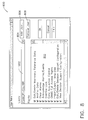
- FIG. 7 is an exemplary screen shot 700 of a rule test display screen 702 .
- Screen 702 includes input data windows including user-defined values 704 , and constant values 706 , operands 708 , and result windows 710 .
- Each step of a test session may be incremented and intermediate values of each increment may be displayed.
- the security model may include password protection for several features within an enterprise, Rule Developer 342 , and/or Rule Sets 280 at bundling. For example, if a security is already being applied to the rule, then the user will be prompted to enter the old password before the security page can be opened.
- a password may be format restricted, for example, the password may be restricted to a combination of alpha and/or numeric characters and a length of six to twelve characters long.
- the security model applies to viewing a logic page, operand mapping, viewing history, and adding of rules to a test session.
- the security setting is carried along with the copied rule and is applied to a rule copied in the same enterprise or across different enterprises. All the security setting may be applied to the pasted rule.
- the user may be is prompted for the password before the copy into the development library is allowed.
- the user may not be allowed to copy multiple rules from an enterprise to a development library or from a development library to an enterprise. However, copying multiple rules may be allowed between two enterprises or between two development libraries.
- a user may be prompted for a password for an initial request to map any operands of the rule. If the rule has “Viewing history” settings enabled, the user may be prompted to enter the password for the rule. A user may be prompted for a password when the user adds a protected rule to a test session. If the user is granted access to the development rule library, the user will have all rights to the rules created under the development rule library.
- the operand mapping feature of a Rule Set 280 in development may be protected, and a user is prompted to enter a password before operand mapping of the Rule Set is permitted.
- distribution security applies to the rules within Rule Set 280 once it has been applied to an asset.
- Encryption refers to the actual physical media of Rule Set 280 (CD-ROM, etc.).
- An ‘Auto Generate’ button may use a random number generator to generate a series of 25 numbers and digits to determine the encryption.
- a distribution security password may be enabled. The password may also be transmitted with the rules within Rule Set 280 when exported. Accordingly, operand mapping of rules will be password-protected after deploying the Rule Set.
- Connecting to a system configuration database may include a Edit/Delete Configuration wherein only users with this level of security will be allowed to edit or delete any Rule Developer 342 objects, including rules, action plans, condition types, and notification plans.
- Connecting to a system configuration database may include an Import/Apply Rule Sets configuration.
- a View Monitoring Support Configuration permits a user to view any Monitoring Support objects.
- the types of rights that may apply to a development library include, for example, but, are not limited to a read only view of the development library, an edit view that permits all the operations on a development library, and administrator rights that permits adding other users to the development library and implicitly selects the other rights, and a security settings view.
- a read only view of the development library an edit view that permits all the operations on a development library
- administrator rights that permits adding other users to the development library and implicitly selects the other rights
- a security settings view Similarly, if the “Edit” right is selected, the “View” rights will be implicitly selected.
- FIG. 9 illustrates an exemplary Rule Set level page 900 that may be used with Rule Developer 342 (shown in FIG. 3 ).
- Rule Developer 342 includes a documentation configuration. Documentation of Rule Sets 280 may be created within Rule Developer 342 and is bundled into Rule Set 280 .
- documentation may be configurable at several levels, for example, a Rule Logic level, a Rule level, and a Rule Set level.
- the Rule Logic level enables the user to document the Rule Logic page. This step of the rule Logic will have no inputs or outputs, and may be a simple, resizable text box.
- the Rule Logic page becomes part of the rule logic and shows on the logic page at all times.
- the Rule level provides rule documentation for a rule.
- Rule Set level page 900 includes a plurality of menu tabs 902 for navigating to specific functional areas and a text box 904 for entering documentation for Rule Set 342 .
- a technical effect of the present invention is to capture expert knowledge in a form that can be created and modified without software coding by an application expert.
- a development system to create expert knowledge rules, test the rules using live data, historical data, user supplied data, and/or data supplied from a third party through a custom interface, commission the rules, and operate the rules permits expert knowledge to be created and bundled in a set of rules that can be protected from unauthorized use and be transmitted to a plurality of monitoring systems without substantial costly modification.
- the knowledge may be captured in the form of rules that relate the outputs of the set of software rules to the inputs of the set of software rules.
- the present invention is described with reference to an industrial plant, numerous other applications are contemplated. It is contemplated that the present invention may be applied to any control system, including facilities, such as commercial facilities, vehicles, for example ships, aircraft, and trains, and office buildings or a campus of buildings, as well as, refineries and midstream liquids facilities, and facilities that produce discrete product outputs, such as, factories.
- facilities such as commercial facilities, vehicles, for example ships, aircraft, and trains, and office buildings or a campus of buildings, as well as, refineries and midstream liquids facilities, and facilities that produce discrete product outputs, such as, factories.
- the above-described systems and methods of creating, testing, protecting, and deploying one or more knowledge rules that are bundled in a modular, electronically transmittable form is cost-effective and highly reliable for facilitating monitoring and managing the operation and maintenance of facilities. More specifically, the methods and systems described herein facilitate determining facility machine health and alerting operators of anomalous conditions. As a result, the methods and systems described herein facilitate reducing plant operating costs in a cost-effective and reliable manner.
Abstract
Description
| |
| ||
| Byte | |||
| 2 | | ||
| Byte | |||
| 3 | Major version of |
||
| Byte 4 | Minor version of |
||
| Byte 5 | NULL | ||
| Byte 6 | NULL | ||
| Byte 7 | NULL | ||
| Byte 8 | NULL | ||
| Byte 9 | | ||
| Byte | |||
| 10 | CheckSumByte | ||
| Byte 11 | CheckSumByte | ||
| Byte 12 | CheckSumByte | ||
| Byte 13 | | ||
| Byte | |||
| 14 | | ||
| Byte | |||
| 15 | | ||
| Byte | |||
| 16 | CheckSumByte | ||
| Byte 17 | CheckSumByte | ||
| Byte 18 | CheckSumByte | ||
| Byte 19 | | ||
| Byte | |||
| 20 | CheckSumByte | ||
| Byte 21 | | ||
| Byte | |||
| 22 | CheckSumByte | ||
| Byte 23 | | ||
| Byte | |||
| 24 | CheckSumByte | ||
| <RuleSetExport> | ||
| <RuleSetID>GUID</RuleSetID> | ||
| <RuleSetName>Name</RuleSetName> | ||
| <RuleSetDescription>DescriptionText</RuleSetDescription> | ||
| <RuleSetVersion>X.XX</RuleSetVersion> | ||
| <RuleSetRevision>Free Entry Text</RuleSetRevision> | ||
| <RuleSetState>Development/Deployed</RuleSetState> | ||
| <RuleSetAsset>Asset Type</RuleSetAsset> | ||
| <CustomRuleCount>N</CustomRuleCount> | ||
| <EnterpriseVersion>X.XX</EnterpriseVersion> | ||
| <CustomRule0> | ||
| <Rule Template> | ||
| Table Entries for Rule Template | ||
| Custom Entries for Rule Template | ||
| </Rule Template> | ||
| </CustomRule0> | ||
| <CustomRule1> | ||
| Custom Rule (Defined by Template | ||
| Importer/Exporter)... | ||
| </CustomRule1> | ||
| i. ... | ||
| ii. ... | ||
| <CustomRuleN> | ||
| i. Custom Rule (Defined by Template | ||
| Importer/Exporter)... | ||
| </CustomRuleN> | ||
| </RuleSetExport> | ||
Claims (42)
Priority Applications (1)
| Application Number | Priority Date | Filing Date | Title |
|---|---|---|---|
| US10/829,585 US7739216B2 (en) | 2004-04-22 | 2004-04-22 | Methods and systems for monitoring and diagnosing machinery by incremently testing a rule |
Applications Claiming Priority (1)
| Application Number | Priority Date | Filing Date | Title |
|---|---|---|---|
| US10/829,585 US7739216B2 (en) | 2004-04-22 | 2004-04-22 | Methods and systems for monitoring and diagnosing machinery by incremently testing a rule |
Publications (2)
| Publication Number | Publication Date |
|---|---|
| US20050240545A1 US20050240545A1 (en) | 2005-10-27 |
| US7739216B2 true US7739216B2 (en) | 2010-06-15 |
Family
ID=35137692
Family Applications (1)
| Application Number | Title | Priority Date | Filing Date |
|---|---|---|---|
| US10/829,585 Active 2026-02-23 US7739216B2 (en) | 2004-04-22 | 2004-04-22 | Methods and systems for monitoring and diagnosing machinery by incremently testing a rule |
Country Status (1)
| Country | Link |
|---|---|
| US (1) | US7739216B2 (en) |
Cited By (5)
| Publication number | Priority date | Publication date | Assignee | Title |
|---|---|---|---|---|
| US8161806B1 (en) | 2010-12-23 | 2012-04-24 | General Electric Company | Method of monitoring engine performance parameters of a gas turbine engine |
| US8600642B2 (en) | 2010-12-23 | 2013-12-03 | General Electric Company | Hub unit for a high temperature electronic monitoring system |
| US8661881B2 (en) | 2010-12-23 | 2014-03-04 | General Electric Company | Hub unit for a high temperature electronic monitoring system |
| US8668381B2 (en) | 2010-12-23 | 2014-03-11 | General Electric Company | High temperature electronic monitoring system |
| US11183875B2 (en) | 2012-01-20 | 2021-11-23 | Salesforce.Com, Inc. | Site management in an on-demand system |
Families Citing this family (26)
| Publication number | Priority date | Publication date | Assignee | Title |
|---|---|---|---|---|
| CN101297294A (en) * | 2004-05-21 | 2008-10-29 | 派拉斯科技术公司 | Graphical re-inspection user setup interface |
| US7236910B1 (en) * | 2004-08-09 | 2007-06-26 | Wood Group Esp, Inc. | Equipment identification, tracking and failure analysis process |
| CA2530781A1 (en) * | 2005-12-14 | 2007-06-14 | Peter F. Werner | Electrical component monitoring system |
| US7742848B2 (en) * | 2005-12-30 | 2010-06-22 | Canadian National Railway Company | System and method for computing rail car switching solutions in a switchyard including logic to re-switch cars for block pull time |
| US7742849B2 (en) | 2005-12-30 | 2010-06-22 | Canadian National Railway Company | System and method for computing car switching solutions in a switchyard using car ETA as a factor |
| US7657348B2 (en) * | 2005-12-30 | 2010-02-02 | Canadian National Railway Company | System and method for computing rail car switching solutions using dynamic classification track allocation |
| US20070179688A1 (en) * | 2005-12-30 | 2007-08-02 | Canadian National Railway Company | System and method for computing rail car switching solutions in a switchyard |
| US20070156298A1 (en) * | 2005-12-30 | 2007-07-05 | Canadian National Railway Company | System and method for computing rail car switching solutions by assessing space availability in a classification track on the basis of arrival profile |
| US7751952B2 (en) * | 2005-12-30 | 2010-07-06 | Canadian National Railway Company | System and method for computing rail car switching solutions in a switchyard including logic to re-switch cars for arrival rate |
| US8060263B2 (en) * | 2005-12-30 | 2011-11-15 | Canadian National Railway Company | System and method for forecasting the composition of an outbound train in a switchyard |
| US7747362B2 (en) * | 2005-12-30 | 2010-06-29 | Canadian National Railway Company | System and method for computing rail car switching solutions by assessing space availability in a classification track on the basis of block pull time |
| US7792616B2 (en) * | 2005-12-30 | 2010-09-07 | Canadian National Railway Company | System and method for computing rail car switching solutions in a switchyard including logic to re-switch cars for block size |
| US8055397B2 (en) | 2005-12-30 | 2011-11-08 | Canadian National Railway Company | System and method for computing rail car switching sequence in a switchyard |
| US7818101B2 (en) * | 2005-12-30 | 2010-10-19 | Canadian National Railway Company | System and method for computing rail car switching solutions in a switchyard using an iterative method |
| US7424328B2 (en) * | 2006-01-03 | 2008-09-09 | De Silvio Louis F | Apparatus and method for wireless process control |
| US20080059005A1 (en) * | 2006-08-31 | 2008-03-06 | Jonny Ray Greiner | System and method for selective on-board processing of machine data |
| US20080059080A1 (en) * | 2006-08-31 | 2008-03-06 | Caterpillar Inc. | Method and system for selective, event-based communications |
| US20080059411A1 (en) * | 2006-08-31 | 2008-03-06 | Caterpillar Inc. | Performance-based job site management system |
| US20080147571A1 (en) * | 2006-09-29 | 2008-06-19 | Caterpillar Inc. | System and method for analyzing machine customization costs |
| US20080082345A1 (en) * | 2006-09-29 | 2008-04-03 | Caterpillar Inc. | System and method for evaluating risks associated with delaying machine maintenance |
| WO2008120552A1 (en) * | 2007-03-29 | 2008-10-09 | Nec Corporation | Diagnostic system |
| US20080270074A1 (en) * | 2007-04-30 | 2008-10-30 | Caterpillar Inc. | User customized machine data acquisition system |
| US8099194B2 (en) * | 2007-11-19 | 2012-01-17 | Prenova, Inc. | Demand control |
| KR101425699B1 (en) * | 2010-05-07 | 2014-08-01 | 엘에스산전 주식회사 | Remote Communication Method for Digital Protective Relay |
| US9648084B2 (en) * | 2012-03-08 | 2017-05-09 | Oracle International Corporation | System and method for providing an in-memory data grid application container |
| US11170116B2 (en) * | 2017-10-19 | 2021-11-09 | 3D Bridge Solutions Inc. | Systems, devices and methods for protecting and exchanging electronic computer files |
Citations (15)
| Publication number | Priority date | Publication date | Assignee | Title |
|---|---|---|---|---|
| US5311562A (en) | 1992-12-01 | 1994-05-10 | Westinghouse Electric Corp. | Plant maintenance with predictive diagnostics |
| US5905989A (en) | 1996-11-27 | 1999-05-18 | Bently Nevada Corporation | Knowledge manager relying on a hierarchical default expert system: apparatus and method |
| US6026348A (en) | 1997-10-14 | 2000-02-15 | Bently Nevada Corporation | Apparatus and method for compressing measurement data correlative to machine status |
| US6092029A (en) | 1998-02-19 | 2000-07-18 | Bently Nevada Corporation | Method and apparatus for diagnosing and controlling rotating stall and surge in rotating machinery |
| US6405139B1 (en) | 1998-09-15 | 2002-06-11 | Bently Nevada Corporation | System for monitoring plant assets including machinery |
| US6421571B1 (en) | 2000-02-29 | 2002-07-16 | Bently Nevada Corporation | Industrial plant asset management system: apparatus and method |
| US6507804B1 (en) | 1997-10-14 | 2003-01-14 | Bently Nevada Corporation | Apparatus and method for compressing measurement data corelative to machine status |
| US6542595B1 (en) * | 1999-01-15 | 2003-04-01 | Alcatel | Process, generating module, server, control module and storage means for the creation of validation rules |
| US6633782B1 (en) | 1999-02-22 | 2003-10-14 | Fisher-Rosemount Systems, Inc. | Diagnostic expert in a process control system |
| US6654932B1 (en) * | 1999-08-03 | 2003-11-25 | International Business Machines Corporation | Validating data within container objects handled by view controllers |
| US6795798B2 (en) * | 2001-03-01 | 2004-09-21 | Fisher-Rosemount Systems, Inc. | Remote analysis of process control plant data |
| US20040189708A1 (en) * | 2003-03-28 | 2004-09-30 | Larcheveque Jean-Marie H. | System and method for real-time validation of structured data files |
| US20040243530A1 (en) * | 2001-07-04 | 2004-12-02 | Akeel Al-Attar | Process-related systems and methods |
| US6965887B2 (en) * | 2001-03-21 | 2005-11-15 | Resolutionebs, Inc. | Rule processing methods for automating a decision and assessing satisfiability of rule-based decision diagrams |
| US20060265689A1 (en) * | 2002-12-24 | 2006-11-23 | Eugene Kuznetsov | Methods and apparatus for processing markup language messages in a network |
-
2004
- 2004-04-22 US US10/829,585 patent/US7739216B2/en active Active
Patent Citations (15)
| Publication number | Priority date | Publication date | Assignee | Title |
|---|---|---|---|---|
| US5311562A (en) | 1992-12-01 | 1994-05-10 | Westinghouse Electric Corp. | Plant maintenance with predictive diagnostics |
| US5905989A (en) | 1996-11-27 | 1999-05-18 | Bently Nevada Corporation | Knowledge manager relying on a hierarchical default expert system: apparatus and method |
| US6507804B1 (en) | 1997-10-14 | 2003-01-14 | Bently Nevada Corporation | Apparatus and method for compressing measurement data corelative to machine status |
| US6026348A (en) | 1997-10-14 | 2000-02-15 | Bently Nevada Corporation | Apparatus and method for compressing measurement data correlative to machine status |
| US6092029A (en) | 1998-02-19 | 2000-07-18 | Bently Nevada Corporation | Method and apparatus for diagnosing and controlling rotating stall and surge in rotating machinery |
| US6405139B1 (en) | 1998-09-15 | 2002-06-11 | Bently Nevada Corporation | System for monitoring plant assets including machinery |
| US6542595B1 (en) * | 1999-01-15 | 2003-04-01 | Alcatel | Process, generating module, server, control module and storage means for the creation of validation rules |
| US6633782B1 (en) | 1999-02-22 | 2003-10-14 | Fisher-Rosemount Systems, Inc. | Diagnostic expert in a process control system |
| US6654932B1 (en) * | 1999-08-03 | 2003-11-25 | International Business Machines Corporation | Validating data within container objects handled by view controllers |
| US6421571B1 (en) | 2000-02-29 | 2002-07-16 | Bently Nevada Corporation | Industrial plant asset management system: apparatus and method |
| US6795798B2 (en) * | 2001-03-01 | 2004-09-21 | Fisher-Rosemount Systems, Inc. | Remote analysis of process control plant data |
| US6965887B2 (en) * | 2001-03-21 | 2005-11-15 | Resolutionebs, Inc. | Rule processing methods for automating a decision and assessing satisfiability of rule-based decision diagrams |
| US20040243530A1 (en) * | 2001-07-04 | 2004-12-02 | Akeel Al-Attar | Process-related systems and methods |
| US20060265689A1 (en) * | 2002-12-24 | 2006-11-23 | Eugene Kuznetsov | Methods and apparatus for processing markup language messages in a network |
| US20040189708A1 (en) * | 2003-03-28 | 2004-09-30 | Larcheveque Jean-Marie H. | System and method for real-time validation of structured data files |
Cited By (7)
| Publication number | Priority date | Publication date | Assignee | Title |
|---|---|---|---|---|
| US8161806B1 (en) | 2010-12-23 | 2012-04-24 | General Electric Company | Method of monitoring engine performance parameters of a gas turbine engine |
| US8600642B2 (en) | 2010-12-23 | 2013-12-03 | General Electric Company | Hub unit for a high temperature electronic monitoring system |
| US8661881B2 (en) | 2010-12-23 | 2014-03-04 | General Electric Company | Hub unit for a high temperature electronic monitoring system |
| US8668381B2 (en) | 2010-12-23 | 2014-03-11 | General Electric Company | High temperature electronic monitoring system |
| US11183875B2 (en) | 2012-01-20 | 2021-11-23 | Salesforce.Com, Inc. | Site management in an on-demand system |
| US11283292B2 (en) * | 2012-01-20 | 2022-03-22 | Salesforce.Com, Inc. | Site management in an on-demand system |
| US11627039B2 (en) | 2012-01-20 | 2023-04-11 | Salesforce.Com, Inc. | Site management in an on-demand system |
Also Published As
| Publication number | Publication date |
|---|---|
| US20050240545A1 (en) | 2005-10-27 |
Similar Documents
| Publication | Publication Date | Title |
|---|---|---|
| US7739216B2 (en) | Methods and systems for monitoring and diagnosing machinery by incremently testing a rule | |
| US7831704B2 (en) | Methods and systems for monitoring and diagnosing machinery | |
| AU2019201086B2 (en) | Method and system for condition monitoring of a group of plants | |
| US10387011B2 (en) | System and method to capture and document cross-product compatibility status information for industrial devices | |
| US9762454B2 (en) | System and method to capture and document cross-product compatibility status information for industrial devices | |
| JP6966159B2 (en) | Process control network rule builder | |
| CN101126928B (en) | For the system and method for maintenance process control system | |
| JP4295952B2 (en) | Method and system for providing remote access | |
| US7346891B2 (en) | System and method for automating generation of an automated sensor network | |
| CN101315558B (en) | Apparatus and methods to access information associated with a process control system | |
| JP2004038596A (en) | Integration of process performance monitoring, process device monitoring, and control | |
| US7469217B2 (en) | Product toolkit system and method | |
| CN101739275A (en) | Systems and methods to provide customized release notes during a software system upgrade of a process control system | |
| Fricks et al. | Importance analysis with Markov chains | |
| US7778719B2 (en) | Method, system, apparatus, and computer-readable medium for providing configure to service for a semiconductor manufacturing service guide system | |
| Tuomi | Application integration for condition based maintenance | |
| Galali | Development of a predictive maintenance application for packaging machines | |
| Wang et al. | A flexible automatic test system for rotating-turbine machinery | |
| García | Automatic Status Logger for a Gas Turbine | |
| Tuomi | Sovellusintegraatio kuntoon perustuvassa kunnossapidossa | |
| Aumeier et al. | Integrated monitoring and surveillance system for SNM. |
Legal Events
| Date | Code | Title | Description |
|---|---|---|---|
| AS | Assignment |
Owner name: GENERAL ELECTRIC COMPANY, NEW YORK Free format text: ASSIGNMENT OF ASSIGNORS INTEREST;ASSIGNORS:SCHACHTELY, ALAN THOMAS;GRANT, JOHN WESLEY;GOMER, RICHARD LEWIS;AND OTHERS;REEL/FRAME:015260/0640 Effective date: 20040406 Owner name: GENERAL ELECTRIC COMPANY,NEW YORK Free format text: ASSIGNMENT OF ASSIGNORS INTEREST;ASSIGNORS:SCHACHTELY, ALAN THOMAS;GRANT, JOHN WESLEY;GOMER, RICHARD LEWIS;AND OTHERS;REEL/FRAME:015260/0640 Effective date: 20040406 |
|
| FEPP | Fee payment procedure |
Free format text: PAYOR NUMBER ASSIGNED (ORIGINAL EVENT CODE: ASPN); ENTITY STATUS OF PATENT OWNER: LARGE ENTITY |
|
| STCF | Information on status: patent grant |
Free format text: PATENTED CASE |
|
| FPAY | Fee payment |
Year of fee payment: 4 |
|
| MAFP | Maintenance fee payment |
Free format text: PAYMENT OF MAINTENANCE FEE, 8TH YEAR, LARGE ENTITY (ORIGINAL EVENT CODE: M1552) Year of fee payment: 8 |
|
| AS | Assignment |
Owner name: BAKER HUGHES, A GE COMPANY, LLC, TEXAS Free format text: ASSIGNMENT OF ASSIGNORS INTEREST;ASSIGNOR:GENERAL ELECTRIC COMPANY;REEL/FRAME:051623/0568 Effective date: 20170703 |
|
| MAFP | Maintenance fee payment |
Free format text: PAYMENT OF MAINTENANCE FEE, 12TH YEAR, LARGE ENTITY (ORIGINAL EVENT CODE: M1553); ENTITY STATUS OF PATENT OWNER: LARGE ENTITY Year of fee payment: 12 |
|
| AS | Assignment |
Owner name: BAKER HUGHES HOLDINGS LLC, TEXAS Free format text: CHANGE OF NAME;ASSIGNOR:BAKER HUGHES, A GE COMPANY, LLC;REEL/FRAME:062519/0262 Effective date: 20200413 |
|
| AS | Assignment |
Owner name: BAKER HUGHES HOLDINGS LLC, TEXAS Free format text: CHANGE OF NAME;ASSIGNOR:BAKER HUGHES, A GE COMPANY, LLC;REEL/FRAME:062591/0249 Effective date: 20200413 |