US7740639B2 - Method and device for the endoscopic application of self-closing medical clips - Google Patents
Method and device for the endoscopic application of self-closing medical clips Download PDFInfo
- Publication number
- US7740639B2 US7740639B2 US10/565,735 US56573504A US7740639B2 US 7740639 B2 US7740639 B2 US 7740639B2 US 56573504 A US56573504 A US 56573504A US 7740639 B2 US7740639 B2 US 7740639B2
- Authority
- US
- United States
- Prior art keywords
- clip
- legs
- catheter tube
- crosspiece
- pull cable
- Prior art date
- Legal status (The legal status is an assumption and is not a legal conclusion. Google has not performed a legal analysis and makes no representation as to the accuracy of the status listed.)
- Active, expires
Links
Images


Classifications
-
- A—HUMAN NECESSITIES
- A61—MEDICAL OR VETERINARY SCIENCE; HYGIENE
- A61B—DIAGNOSIS; SURGERY; IDENTIFICATION
- A61B17/00—Surgical instruments, devices or methods, e.g. tourniquets
- A61B17/12—Surgical instruments, devices or methods, e.g. tourniquets for ligaturing or otherwise compressing tubular parts of the body, e.g. blood vessels, umbilical cord
- A61B17/122—Clamps or clips, e.g. for the umbilical cord
- A61B17/1227—Spring clips
-
- A—HUMAN NECESSITIES
- A61—MEDICAL OR VETERINARY SCIENCE; HYGIENE
- A61B—DIAGNOSIS; SURGERY; IDENTIFICATION
- A61B17/00—Surgical instruments, devices or methods, e.g. tourniquets
- A61B17/12—Surgical instruments, devices or methods, e.g. tourniquets for ligaturing or otherwise compressing tubular parts of the body, e.g. blood vessels, umbilical cord
- A61B17/128—Surgical instruments, devices or methods, e.g. tourniquets for ligaturing or otherwise compressing tubular parts of the body, e.g. blood vessels, umbilical cord for applying or removing clamps or clips
- A61B17/1285—Surgical instruments, devices or methods, e.g. tourniquets for ligaturing or otherwise compressing tubular parts of the body, e.g. blood vessels, umbilical cord for applying or removing clamps or clips for minimally invasive surgery
-
- A—HUMAN NECESSITIES
- A61—MEDICAL OR VETERINARY SCIENCE; HYGIENE
- A61B—DIAGNOSIS; SURGERY; IDENTIFICATION
- A61B17/00—Surgical instruments, devices or methods, e.g. tourniquets
- A61B17/12—Surgical instruments, devices or methods, e.g. tourniquets for ligaturing or otherwise compressing tubular parts of the body, e.g. blood vessels, umbilical cord
- A61B2017/12004—Surgical instruments, devices or methods, e.g. tourniquets for ligaturing or otherwise compressing tubular parts of the body, e.g. blood vessels, umbilical cord for haemostasis, for prevention of bleeding
Definitions
- the present invention relates to a method and device for endoscopic application of self-closing medical clips, especially for stopping internal hemorrhages, in which a catheter tube with its distal end is placed in the body of the living being to be treated.
- An object of the present invention is to provide a process which permits multiple placement of hemostatic clips in immediate succession, without the need to provide the endoscopic device with another clip outside of the body for each application.
- This object is basically achieved by a process according to the present invention, where the catheter tube itself is used as a magazine which is loaded with several clips before implementing the pertinent treatment.
- Multiple application of hemostatic clips in immediate succession is made possible without the endoscopic device needing to be removed from the body after each clip application. Rather, the frontmost clip can be pushed out of the distal end of the catheter tube, opened by an actuating element acting on it, and placed on the hemorrhage site to be treated.
- the actuating element is detached from the clip so that it is released and its self-closing legs effect the hemostatic clamping, after which the actuating element is functionally linked to the clip which follows in sequence in the catheter tube, so that if necessary the next clip can be applied without delay.
- the clips are already loaded by the manufacturer.
- flexible spiral tubes resistant to tension and compression, but also tube-like flexible application bodies can be used as the catheter tube.
- a control part converts the actuation force of the actuating element, which can be controlled by the operator of the device into the opening motion of the legs of the clip.
- the control part is located on the distal end of a sleeve-like receiving part associated with the respective clip.
- the clip is shaped on its legs adjacent to each other such that when the clip is inserted into the receiving part, an opening motion of the free leg ends takes place by the kink of the two legs which forms an arch striking the control part.
- the legs of the clip are released again in order to be closed by their own elasticity at the application site.
- This closing process can be further promoted by deformation at the kink of the clip effected by the sleeve-like receiving part and, in certain configurations, can also be replaced exclusively by the indicated deformation.
- the actuating element can be a pulling element
- the control part can be a beveled control surface located on the end edge of the sleeve-like receiving part.
- the opening and subsequent closing of the legs of the clip which is to be applied are effected by pulling the clip into its receiving part.
- the opening motion takes place by the kink of the legs striking the control surface.
- Subsequently pulling the kinks through the receiving part effects the clip legs being released for the closing motion as soon as the kinks of the legs have run through the sleeve-shaped receiving part.
- the beveled control surface can also be formed by the curved control surface's running convexly or concavely.
- the pulling element can be a pull cable.
- each clip can have two adjacent through holes.
- the cable extends through those holes in a loop, such that it extends in an advancing strand to the clip and back from the latter back in a retreating strand to the operator means.
- the section of the end crosspiece of the clip located between the through holes is made as a predetermined breaking point which can be broken by the pulling force of the pull cable acting by the loop. The pull cable can then be easily detached from the clip after completion of the actuating process.
- a blocking element permits the passage of the sleeve-like receiving part with the respective clip only in the exit direction forward, and supports the sleeve-like receiving part against the motion effected by the pulling force of the pull cable.
- these embodiments can be further configured such that in the catheter tube there are several clips with the respective sleeve-like receiving part in succession.
- the pull cable with the advancing strand and with the retreating strand is guided in each case through one or the other through hole of the end crosspieces of all clips.
- FIG. 1 is a schematically simplified, side elevational view in section of only the distal end section of the catheter tube as a component of the device according to one embodiment of the present invention, with this section being shown on an enlarged scale compared to the natural size;
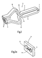
- FIG. 2 is a perspective view of a self-closing medical clip drawn on a still larger scale, for use in the device of the present invention
- FIG. 2 a is a further enlarged perspective view of only the end crosspiece of the clip of FIG. 2 , which crosspiece is provided with a predetermined breaking point;
- FIGS. 3 and 4 are schematic, side elevational views of the device of FIG. 1 illustrating the movements and forces for opening of the clip;
- FIGS. 5 to 13 are schematic, side elevational views of only the distal (front) end of the catheter tube of FIG. 1 , with the clip having emerged and with the respective sleeve-like receiving part, successive operating states being shown as the opening and closing cycle of the clip proceeds, and
- FIG. 14 is a highly enlarged perspective view of a blocking element designed as a collet for the distal end of the catheter tube of FIG. 1 .
- FIG. 1 shows the distal end section of the catheter tube 1 as a component of an exemplary embodiment of the device of the present invention.
- the catheter tube 1 extends through the associated working space of a flexible endoscope which can be of conventional design in medical technology and which contains at least one other inner working space for endoscope optics including illumination and/or for other purposes (for example, suction).
- the proximal end (not shown) of the catheter tube 1 is functionally connected to the manipulation and operator means located on that end of the endoscope.
- the outside diameter of the catheter tube 1 is 2.7 mm corresponding to the clearance of the working spaces in flexible endoscopes.
- the device of the present invention is suited for application of self-closing medical clips 3 of a design as can be seen most clearly from FIGS. 2 to 4 .
- the clip 3 is formed from a material such as high quality steel customarily used for medical purposes, and has two legs 5 which, without crossing one another, are adjacent to each other and are bent toward each other on the clip free leg end 7 .
- the legs 5 are connected to each other by an end crosspiece 9 having through two through holes 11 adjacent to each other.
- each leg 5 has a first kink 13 arched to the outside and closer to end crosspiece 9 than to the leg end 7 , and a second kink 15 arched to the inside and closer to the leg end 7 than the first kink.
- the second kinks is together form a support point for the mutual contact of the legs 5 . From the second kink 15 , the remaining sections of the legs 5 extend more or less parallel to each other to the free leg end 7 when the clip 3 is in the closed state, as is shown in FIGS. 2 and 3 , i.e., the initial state of the clip 3 .
- FIGS. 3 and 4 using the sleeve 17 and a counter bearing 19 show the forces which effect opening of the legs 5 under the action of a pulling force applied by a pull cable 21 to the clip 3 corresponding to the action arrow 23 in FIG. 4 .
- a force directed inwardly acts on each first kink 13 , the legs 5 being extended (see arrows 29 in FIG. 3 ) with the second kinks 15 for mutual support. Due to the pulling force which continues to act (arrow 23 ), the legs 5 at the support point of the second kinks 15 seesaw on each other, which results in the opening-pivoting of the legs 5 according to arrows 31 ( FIG. 4 ).
- FIG. 1 shows the catheter tube 1 with several clips 3 in succession, each forming a unit with a sleeve-like receiving part 33 .
- the receiving part 33 corresponds in the interaction of its front control surface 25 with the respective clip 3 of the sleeve 17 , as shown in FIGS. 3 and 4 to illustrate the forces acting on the clip 3 .
- two clips 3 with the respective receiving parts 33 are accommodated in the catheter tube 1 .
- the catheter tube 1 can be provided as a magazine for 2 to 10 clips, preferably for 2 to 5 clips or more.
- the units including the clip 3 and receiving part 33 can be moved in the catheter tube 1 by a sliding tube 35 with a front end edge 37 forming a plunger for contact with the adjacent receiving part 33 and with a proximal end which can be manipulated as part of the actuating means from the operator means on the outer actuating end of the endoscope.
- the pull cable 21 extends in the catheter tube 1 as the actuating element in two strands 24 through the through holes 11 (see FIG. 2 ) of each clip 3 .
- a loop 39 is formed on the end crosspiece 9 ( FIG. 1 ).
- the loop 39 is also shown in the schematics of FIGS. 3 and 4 .
- the strands 24 of the pull cable 21 are routed in the catheter tube 1 through the sliding tube 35 as the actuating element as far as the operator means on the outer end of the endoscope.
- the clips 3 are arranged in succession in the catheter tube 1 with the associated receiving parts 33 , and are advanced by the sliding tube 35 until the receiving part 33 of the frontmost clip 3 has left the catheter tube 1 , more precisely, has passed through a blocking element 41 mounted on the distal end of the catheter tube 1 . After passing through the blocking element 41 , this receiving part 33 with the respective clip 3 is in the position shown in FIG. 5 .
- FIG. 14 shows the blocking element 41 separately.
- the blocking element 41 is a tube piece 43 which lengthens the catheter tube 1 and which has longitudinal slots 44 in its end part so that jaws 45 are formed as a kind of collet and under normal conditions reduce the passage clearance of the tube piece 43 .
- the passage of the receiving part 33 in a slightly elastic way spreads the jaws 45 which assume the blocking position shown in FIGS. 5 to 13 after emergence of the receiving part 33 , so that the receiving part 33 , having emerged, is supported against moving backward.
- a central, projecting shoulder 47 of the receiving part 33 engages as a centering piece between the jaws 45 of the blocking element 41 .
- FIGS. 5 to 13 illustrate in a highly simplified schematic the progression of the opening and closing cycle of the clip 3 with the receiving part 33 , which clip is to be applied and which has been pushed out of the blocking element 41 .
- This entire cycle is effected by pulling on the pull cable 21 .
- FIG. 5 shows the clip 3 activated for application with the sleeve-like receiving part 33 having been pushed out of the blocking element 41 , the clip 3 not yet having been pulled into the receiving part 33 by the pull cable 21 to the extent that the first kinks 13 of the legs 5 would strike the beveled control surface 25 of the receiving part 33 .
- the beveled control surface 25 corresponds to the oblique surface 25 on the sleeve 17 already discussed using the operating diagrams 3 and 4 .
- FIGS. 6 to 9 show the operating states which arise in succession by pulling the pull cable 21 .
- the legs 5 of the clip are progressively opened by the first kinks 13 striking the control surface 25 until the state of complete opening is reached as shown in FIG. 9 .
- FIGS. 10 to 13 shows the closing cycle which results as the pull cable 21 continues to be pulled.
- the legs 5 close due to the inherent elasticity of the clip 3 and/or its deformation being completely released, as soon as the clip 3 has been pulled correspondingly far through the receiving part 33 such that an opening force is no longer being applied by the first kinks 13 .
- This state is reached when the clip 3 is being pulled further beyond the position shown in FIG. 13 through the receiving part 33 .
- the pull cable 21 continues to be pulled to detach the pull cable from the applied clip.
- the applied clip is supported with its end having the end crosspiece 9 ( FIG.
- the clip at least partially transversely to its opening direction has blade-like widenings (not shown) on the legs 5 between the leg end 7 and the assignable second kink 15 and oppositely adjacent to the second kink, which widenings permit an interlocking option of the clip 3 in the sleeve-like receiving part 33 so that the necessary opposing holding force is thus formed for pulling off the pull cable 21 by the predetermined breaking point 51 .
- This blade-like widening adjoins flanking on either side of the respective leg 5 of the clip 3 .
- a predetermined breaking point 51 is dimensioned such that the loop 39 of the pull cable 21 effects tearing through of the predetermined breaking point 51 when a predetermined pulling force is applied, which in practical embodiments is approximately 40 N.
- the applied clip 3 with the associated receiving part 33 thus remains at the treatment site, while after the process of tearing off, the pull cable 21 as a loop 39 automatically adjoins the end crosspiece 9 of the following clip which can be advanced by pushing forward by the sliding tube 35 for the immediately following application process.
- the predetermined breaking point 51 can be made as shown in FIG. 2 . It is also possible to make the predetermined breaking point from a different material which can be easily torn and which is different from that remaining material of the end crosspiece 9 . Furthermore, it is also possible to make the end crosspiece 9 uniform in its material to form the predetermined breaking point and the end crosspiece 9 tears if a definable maximum force is exceeded with the pull cable 21 .
- the collet shown in FIG. 14 is fixed with its tube piece 43 as shown in FIG. 1 on the inside circumference of the free end of the catheter tube 1 . It is also possible for the tube piece 43 to enclose the respective free end of the catheter tube 1 and to be held seated there by an adhesive connection and/or force fit.
- the entire application process can be carried out by pulling on the pull cable which is provided as the actuation element and which can be a fine steel cable.
- the pull cable is moved automatically into contact with the end crosspiece 9 of the following clip 3 in the catheter tube 1 .
- the device is then again immediately ready for the following application process.
- the clip can also be used for marking purposes, for example, in the field of diagnostics.
- surgical procedures can be carried out in which the clip is used as a surgical instrument, for example, for removing polyps in the gastrointestinal tract or the like.
Abstract
Description
Claims (18)
Applications Claiming Priority (4)
| Application Number | Priority Date | Filing Date | Title |
|---|---|---|---|
| DE10334083.1 | 2003-07-26 | ||
| DE10334083A DE10334083A1 (en) | 2003-07-26 | 2003-07-26 | Method and device for endoscopic application of closing medical clips |
| DE10334083 | 2003-07-26 | ||
| PCT/EP2004/007694 WO2005009254A1 (en) | 2003-07-26 | 2004-07-13 | Method and device for the endoscopic application of self-closing medical clips |
Publications (2)
| Publication Number | Publication Date |
|---|---|
| US20060271072A1 US20060271072A1 (en) | 2006-11-30 |
| US7740639B2 true US7740639B2 (en) | 2010-06-22 |
Family
ID=34088841
Family Applications (1)
| Application Number | Title | Priority Date | Filing Date |
|---|---|---|---|
| US10/565,735 Active 2025-12-23 US7740639B2 (en) | 2003-07-26 | 2004-07-13 | Method and device for the endoscopic application of self-closing medical clips |
Country Status (10)
| Country | Link |
|---|---|
| US (1) | US7740639B2 (en) |
| EP (1) | EP1648313B1 (en) |
| JP (2) | JP2007500020A (en) |
| AT (1) | ATE433715T1 (en) |
| DE (2) | DE10334083A1 (en) |
| DK (1) | DK1648313T3 (en) |
| ES (1) | ES2326888T3 (en) |
| PL (1) | PL1648313T3 (en) |
| PT (1) | PT1648313E (en) |
| WO (1) | WO2005009254A1 (en) |
Cited By (75)
| Publication number | Priority date | Publication date | Assignee | Title |
|---|---|---|---|---|
| US20070028435A1 (en) * | 2005-06-22 | 2007-02-08 | Raymond Ormachea | Device for securing trim to a seat |
| US20080140089A1 (en) * | 2004-12-24 | 2008-06-12 | Junichi Kogiso | Ligation Apparatus |
| US20090275958A1 (en) * | 2003-03-17 | 2009-11-05 | Sumitomo Bakelite Company | Clip and clipping instrument for biological tissues |
| US20110054498A1 (en) * | 2008-05-05 | 2011-03-03 | Niti Surgical Solutions Ltd. | Endoscopic compression clip and system and method for use thereof |
| US20110152887A1 (en) * | 2009-12-22 | 2011-06-23 | Wilson-Cook Medical Inc. | Medical devices with detachable pivotable jaws |
| US8545519B2 (en) | 2009-12-22 | 2013-10-01 | Cook Medical Technologies Llc | Medical devices with detachable pivotable jaws |
| US20140222028A1 (en) * | 2011-09-15 | 2014-08-07 | I.B.I. Israel Biomedical Innovations Ltd. | Surgical fastener having a snap lock and devices deploying it |
| US8858588B2 (en) | 2010-10-11 | 2014-10-14 | Cook Medical Technologies Llc | Medical devices with detachable pivotable jaws |
| US8939997B2 (en) | 2010-10-11 | 2015-01-27 | Cook Medical Technologies Llc | Medical devices with detachable pivotable jaws |
| US8979891B2 (en) | 2010-12-15 | 2015-03-17 | Cook Medical Technologies Llc | Medical devices with detachable pivotable jaws |
| US20150374392A1 (en) * | 2013-05-14 | 2015-12-31 | Mubashir H. Khan | Endoscopic snare combined with a clip applier |
| US9339270B2 (en) | 2010-10-11 | 2016-05-17 | Cook Medical Technologies Llc | Medical devices with detachable pivotable jaws |
| US10010336B2 (en) | 2009-12-22 | 2018-07-03 | Cook Medical Technologies, Inc. | Medical devices with detachable pivotable jaws |
| US20190231352A1 (en) * | 2015-10-23 | 2019-08-01 | Kaneka Corporation | Medical clip |
| US10426489B2 (en) | 2016-11-01 | 2019-10-01 | Covidien Lp | Endoscopic reposable surgical clip applier |
| US10492795B2 (en) | 2016-11-01 | 2019-12-03 | Covidien Lp | Endoscopic surgical clip applier |
| US10524786B2 (en) | 2013-05-14 | 2020-01-07 | Mubashir H. Khan | Spring-closing endoscopic clip where the spring action can also reverse the clip prior anytime before full ejection |
| US10548602B2 (en) | 2017-02-23 | 2020-02-04 | Covidien Lp | Endoscopic surgical clip applier |
| US10603038B2 (en) | 2017-02-22 | 2020-03-31 | Covidien Lp | Surgical clip applier including inserts for jaw assembly |
| US10610236B2 (en) | 2016-11-01 | 2020-04-07 | Covidien Lp | Endoscopic reposable surgical clip applier |
| US10639032B2 (en) | 2017-06-30 | 2020-05-05 | Covidien Lp | Endoscopic surgical clip applier including counter assembly |
| US10639044B2 (en) | 2016-10-31 | 2020-05-05 | Covidien Lp | Ligation clip module and clip applier |
| US10653429B2 (en) | 2017-09-13 | 2020-05-19 | Covidien Lp | Endoscopic surgical clip applier |
| US10660723B2 (en) | 2017-06-30 | 2020-05-26 | Covidien Lp | Endoscopic reposable surgical clip applier |
| US10660651B2 (en) | 2016-10-31 | 2020-05-26 | Covidien Lp | Endoscopic reposable surgical clip applier |
| US10660725B2 (en) | 2017-02-14 | 2020-05-26 | Covidien Lp | Endoscopic surgical clip applier including counter assembly |
| US10675112B2 (en) | 2017-08-07 | 2020-06-09 | Covidien Lp | Endoscopic surgical clip applier including counter assembly |
| US10675043B2 (en) | 2017-05-04 | 2020-06-09 | Covidien Lp | Reposable multi-fire surgical clip applier |
| US10702280B2 (en) | 2015-11-10 | 2020-07-07 | Covidien Lp | Endoscopic reposable surgical clip applier |
| US10702279B2 (en) | 2015-11-03 | 2020-07-07 | Covidien Lp | Endoscopic surgical clip applier |
| US10709455B2 (en) | 2017-02-02 | 2020-07-14 | Covidien Lp | Endoscopic surgical clip applier |
| US10722236B2 (en) | 2017-12-12 | 2020-07-28 | Covidien Lp | Endoscopic reposable surgical clip applier |
| US10722235B2 (en) | 2017-05-11 | 2020-07-28 | Covidien Lp | Spring-release surgical clip |
| US10743887B2 (en) | 2017-12-13 | 2020-08-18 | Covidien Lp | Reposable multi-fire surgical clip applier |
| US10758244B2 (en) | 2017-02-06 | 2020-09-01 | Covidien Lp | Endoscopic surgical clip applier |
| US10758245B2 (en) | 2017-09-13 | 2020-09-01 | Covidien Lp | Clip counting mechanism for surgical clip applier |
| US10765431B2 (en) | 2016-01-18 | 2020-09-08 | Covidien Lp | Endoscopic surgical clip applier |
| US10786273B2 (en) | 2018-07-13 | 2020-09-29 | Covidien Lp | Rotation knob assemblies for handle assemblies |
| US10786263B2 (en) | 2017-08-15 | 2020-09-29 | Covidien Lp | Endoscopic reposable surgical clip applier |
| US10786262B2 (en) | 2017-08-09 | 2020-09-29 | Covidien Lp | Endoscopic reposable surgical clip applier |
| US10806464B2 (en) | 2016-08-11 | 2020-10-20 | Covidien Lp | Endoscopic surgical clip applier and clip applying systems |
| US10806463B2 (en) | 2011-11-21 | 2020-10-20 | Covidien Lp | Surgical clip applier |
| US10828036B2 (en) | 2017-11-03 | 2020-11-10 | Covidien Lp | Endoscopic surgical clip applier and handle assemblies for use therewith |
| US10828044B2 (en) | 2015-03-10 | 2020-11-10 | Covidien Lp | Endoscopic reposable surgical clip applier |
| US10835260B2 (en) | 2017-09-13 | 2020-11-17 | Covidien Lp | Endoscopic surgical clip applier and handle assemblies for use therewith |
| US10835341B2 (en) | 2017-09-12 | 2020-11-17 | Covidien Lp | Endoscopic surgical clip applier and handle assemblies for use therewith |
| US10849630B2 (en) | 2017-12-13 | 2020-12-01 | Covidien Lp | Reposable multi-fire surgical clip applier |
| US10905425B2 (en) | 2015-11-10 | 2021-02-02 | Covidien Lp | Endoscopic reposable surgical clip applier |
| US10932793B2 (en) | 2016-01-11 | 2021-03-02 | Covidien Lp | Endoscopic reposable surgical clip applier |
| US10932791B2 (en) | 2017-11-03 | 2021-03-02 | Covidien Lp | Reposable multi-fire surgical clip applier |
| US10932790B2 (en) | 2017-08-08 | 2021-03-02 | Covidien Lp | Geared actuation mechanism and surgical clip applier including the same |
| US10945734B2 (en) | 2017-11-03 | 2021-03-16 | Covidien Lp | Rotation knob assemblies and surgical instruments including the same |
| US10959737B2 (en) | 2017-12-13 | 2021-03-30 | Covidien Lp | Reposable multi-fire surgical clip applier |
| US10993721B2 (en) | 2018-04-25 | 2021-05-04 | Covidien Lp | Surgical clip applier |
| US11026696B2 (en) | 2012-05-31 | 2021-06-08 | Covidien Lp | Endoscopic clip applier |
| US11051827B2 (en) | 2018-01-16 | 2021-07-06 | Covidien Lp | Endoscopic surgical instrument and handle assemblies for use therewith |
| US11051828B2 (en) | 2018-08-13 | 2021-07-06 | Covidien Lp | Rotation knob assemblies and surgical instruments including same |
| US11058432B2 (en) | 2015-01-15 | 2021-07-13 | Covidien Lp | Endoscopic reposable surgical clip applier |
| US11071553B2 (en) | 2016-08-25 | 2021-07-27 | Covidien Lp | Endoscopic surgical clip applier and clip applying systems |
| US11116513B2 (en) | 2017-11-03 | 2021-09-14 | Covidien Lp | Modular surgical clip cartridge |
| US11116514B2 (en) | 2017-02-06 | 2021-09-14 | Covidien Lp | Surgical clip applier with user feedback feature |
| US11147566B2 (en) | 2018-10-01 | 2021-10-19 | Covidien Lp | Endoscopic surgical clip applier |
| US11213299B2 (en) | 2010-02-25 | 2022-01-04 | Covidien Lp | Articulating endoscopic surgical clip applier |
| US11219463B2 (en) | 2018-08-13 | 2022-01-11 | Covidien Lp | Bilateral spring for surgical instruments and surgical instruments including the same |
| US11246601B2 (en) | 2018-08-13 | 2022-02-15 | Covidien Lp | Elongated assemblies for surgical clip appliers and surgical clip appliers incorporating the same |
| US11278267B2 (en) | 2018-08-13 | 2022-03-22 | Covidien Lp | Latch assemblies and surgical instruments including the same |
| US11278287B2 (en) | 2011-12-29 | 2022-03-22 | Covidien Lp | Surgical clip applier with integrated clip counter |
| US11344316B2 (en) | 2018-08-13 | 2022-05-31 | Covidien Lp | Elongated assemblies for surgical clip appliers and surgical clip appliers incorporating the same |
| US11376015B2 (en) | 2017-11-03 | 2022-07-05 | Covidien Lp | Endoscopic surgical clip applier and handle assemblies for use therewith |
| US11426176B2 (en) | 2013-05-14 | 2022-08-30 | Mubashir H. Khan | Cartridge with multi-clip dispensing provisions |
| US11510682B2 (en) | 2008-08-25 | 2022-11-29 | Covidien Lp | Surgical clip applier and method of assembly |
| US11524398B2 (en) | 2019-03-19 | 2022-12-13 | Covidien Lp | Gear drive mechanisms for surgical instruments |
| US11583291B2 (en) | 2017-02-23 | 2023-02-21 | Covidien Lp | Endoscopic surgical clip applier |
| US11723669B2 (en) | 2020-01-08 | 2023-08-15 | Covidien Lp | Clip applier with clip cartridge interface |
| US11779340B2 (en) | 2020-01-02 | 2023-10-10 | Covidien Lp | Ligation clip loading device |
Families Citing this family (59)
| Publication number | Priority date | Publication date | Assignee | Title |
|---|---|---|---|---|
| EP3443915B2 (en) | 2003-09-30 | 2024-01-31 | Boston Scientific Scimed, Inc. | Apparatus for deployment of a hemostatic clip |
| US7494461B2 (en) | 2003-09-30 | 2009-02-24 | Boston Scientific Scimed, Inc. | Through the scope tension member release clip |
| EP1684641B1 (en) | 2003-11-07 | 2012-02-15 | Scimed Life Systems, Inc. | Endoscopic hemoscopic clipping apparatus |
| CA2869759A1 (en) | 2004-10-08 | 2006-04-20 | Tyco Healthcare Group Lp | Apparatus for applying surgical clips |
| US8409222B2 (en) | 2004-10-08 | 2013-04-02 | Covidien Lp | Endoscopic surgical clip applier |
| US9763668B2 (en) | 2004-10-08 | 2017-09-19 | Covidien Lp | Endoscopic surgical clip applier |
| US7717926B2 (en) | 2004-10-08 | 2010-05-18 | Tyco Healthcare Group Lp | Endoscopic surgical clip applier |
| US7819886B2 (en) | 2004-10-08 | 2010-10-26 | Tyco Healthcare Group Lp | Endoscopic surgical clip applier |
| US8080021B2 (en) | 2005-01-11 | 2011-12-20 | Boston Scientific Scimed, Inc. | Multiple clip deployment magazine |
| EP2314232B1 (en) | 2006-10-17 | 2015-03-25 | Covidien LP | Apparatus for applying surgical clips |
| JP4716513B2 (en) * | 2006-11-09 | 2011-07-06 | Hoya株式会社 | Endoscopic clip device |
| CA2868909A1 (en) | 2007-03-26 | 2008-10-02 | Tyco Healthcare Group Lp | Endoscopic surgical clip applier |
| WO2008127968A2 (en) | 2007-04-11 | 2008-10-23 | Tyco Healthcare Group Lp | Surgical clip applier |
| US8162959B2 (en) | 2007-05-03 | 2012-04-24 | Boston Scientific Scimed, Inc. | Single stage hemostasis clipping device |
| JP4981536B2 (en) * | 2007-06-21 | 2012-07-25 | Hoya株式会社 | Endoscopic clip device |
| JP5064334B2 (en) * | 2008-08-21 | 2012-10-31 | 富士フイルム株式会社 | Clip package and clip loading method |
| US8056565B2 (en) | 2008-08-25 | 2011-11-15 | Tyco Healthcare Group Lp | Surgical clip applier and method of assembly |
| US20110208212A1 (en) | 2010-02-19 | 2011-08-25 | Zergiebel Earl M | Surgical clip applier |
| US8585717B2 (en) | 2008-08-29 | 2013-11-19 | Covidien Lp | Single stroke endoscopic surgical clip applier |
| US8267944B2 (en) | 2008-08-29 | 2012-09-18 | Tyco Healthcare Group Lp | Endoscopic surgical clip applier with lock out |
| US9358015B2 (en) | 2008-08-29 | 2016-06-07 | Covidien Lp | Endoscopic surgical clip applier with wedge plate |
| US8409223B2 (en) | 2008-08-29 | 2013-04-02 | Covidien Lp | Endoscopic surgical clip applier with clip retention |
| US8734469B2 (en) | 2009-10-13 | 2014-05-27 | Covidien Lp | Suture clip applier |
| US9186136B2 (en) | 2009-12-09 | 2015-11-17 | Covidien Lp | Surgical clip applier |
| US8545486B2 (en) | 2009-12-15 | 2013-10-01 | Covidien Lp | Surgical clip applier |
| US8403946B2 (en) | 2010-07-28 | 2013-03-26 | Covidien Lp | Articulating clip applier cartridge |
| US8968337B2 (en) | 2010-07-28 | 2015-03-03 | Covidien Lp | Articulating clip applier |
| US9011464B2 (en) | 2010-11-02 | 2015-04-21 | Covidien Lp | Self-centering clip and jaw |
| US9186153B2 (en) | 2011-01-31 | 2015-11-17 | Covidien Lp | Locking cam driver and jaw assembly for clip applier |
| US9775623B2 (en) | 2011-04-29 | 2017-10-03 | Covidien Lp | Surgical clip applier including clip relief feature |
| US9364239B2 (en) | 2011-12-19 | 2016-06-14 | Covidien Lp | Jaw closure mechanism for a surgical clip applier |
| US9408610B2 (en) | 2012-05-04 | 2016-08-09 | Covidien Lp | Surgical clip applier with dissector |
| US9968362B2 (en) | 2013-01-08 | 2018-05-15 | Covidien Lp | Surgical clip applier |
| US9113892B2 (en) | 2013-01-08 | 2015-08-25 | Covidien Lp | Surgical clip applier |
| US9750500B2 (en) | 2013-01-18 | 2017-09-05 | Covidien Lp | Surgical clip applier |
| DE102013011192A1 (en) | 2013-07-04 | 2015-01-08 | Carl Stahl Gmbh | Device for the endoscopic application of at least one closing medical clip |
| DE102013011191A1 (en) | 2013-07-04 | 2015-01-08 | Carl Stahl Gmbh | Device for endoscopic application of closing medical clips |
| DE102013011199A1 (en) | 2013-07-04 | 2015-01-08 | Carl Stahl Gmbh | Medical clip |
| DE112014003129A5 (en) | 2013-07-04 | 2016-04-21 | medwork GmbH | Medical clip |
| US9775624B2 (en) | 2013-08-27 | 2017-10-03 | Covidien Lp | Surgical clip applier |
| US10702278B2 (en) | 2014-12-02 | 2020-07-07 | Covidien Lp | Laparoscopic surgical ligation clip applier |
| US9931124B2 (en) | 2015-01-07 | 2018-04-03 | Covidien Lp | Reposable clip applier |
| US10292712B2 (en) | 2015-01-28 | 2019-05-21 | Covidien Lp | Surgical clip applier with integrated cutter |
| EP3366236B1 (en) * | 2015-10-23 | 2021-10-13 | Hangzhou Ags Medtech Co., Ltd. | Ligation device |
| WO2017066986A1 (en) * | 2015-10-23 | 2017-04-27 | 杭州安杰思医学科技有限公司 | Multi-clip ligation device |
| US10390831B2 (en) | 2015-11-10 | 2019-08-27 | Covidien Lp | Endoscopic reposable surgical clip applier |
| CA2958160A1 (en) | 2016-02-24 | 2017-08-24 | Covidien Lp | Endoscopic reposable surgical clip applier |
| CN109661202B (en) * | 2016-09-20 | 2021-08-31 | 波士顿科学国际有限公司 | Reloadable applicator for hemostatic clamps |
| US10863992B2 (en) | 2017-08-08 | 2020-12-15 | Covidien Lp | Endoscopic surgical clip applier |
| JP7330964B2 (en) * | 2017-11-15 | 2023-08-22 | ユナイテッド ステイツ エンドスコピー グループ,インコーポレイテッド | Clips and clip assemblies |
| KR101918711B1 (en) * | 2018-01-08 | 2018-11-14 | 주식회사 인코아 | Medical clip applier |
| US11259887B2 (en) | 2018-08-10 | 2022-03-01 | Covidien Lp | Feedback mechanisms for handle assemblies |
| US11253267B2 (en) | 2018-08-13 | 2022-02-22 | Covidien Lp | Friction reduction mechanisms for handle assemblies |
| US11033256B2 (en) | 2018-08-13 | 2021-06-15 | Covidien Lp | Linkage assembly for reusable surgical handle assemblies |
| CN109394291A (en) * | 2018-12-17 | 2019-03-01 | 江苏常美医疗器械有限公司 | Stop blooding clip assembly |
| US11622765B2 (en) * | 2019-01-03 | 2023-04-11 | Olympus Corporation | Clipping device for large defects, perforations and fistulas |
| CN109805977B (en) * | 2019-03-21 | 2024-03-05 | 南微医学科技股份有限公司 | Medical hemostatic clamp |
| CN110101425A (en) * | 2019-05-08 | 2019-08-09 | 江苏常美医疗器械有限公司 | Running fire hemostatic clamp |
| CN112426247B (en) * | 2020-12-04 | 2022-05-31 | 中国人民解放军陆军特色医学中心 | Head fixing device for explosive injury animal |
Citations (9)
| Publication number | Priority date | Publication date | Assignee | Title |
|---|---|---|---|---|
| US4416266A (en) | 1981-05-15 | 1983-11-22 | The United States Of America As Represented By The Administrator Of The National Aeronautics And Space Administration | Medical clip |
| US4671282A (en) | 1985-10-04 | 1987-06-09 | Tretbar Lawrence L | Clip apparatus |
| US5174276A (en) | 1988-11-18 | 1992-12-29 | Hillway Surgical Limited | Endoscope device for applying an aneurysm clip |
| US20020045909A1 (en) * | 2000-10-16 | 2002-04-18 | Olympus Optical Co., Ltd. | Physiological tissue clipping apparatus, clipping method and clip unit mounting method |
| US20020128667A1 (en) * | 2001-03-07 | 2002-09-12 | Olympus Optical Co., Ltd. | Apparatus for ligating living tissues |
| DE10203956A1 (en) | 2001-02-05 | 2002-09-26 | Olympus Optical Co | Surgical tissue clip placer tool comprises manipulating wire moving and rotating in endoscope tube to grip and release clip in response to applied manipulative release force. |
| US20020138083A1 (en) | 2001-03-26 | 2002-09-26 | Olympus Optical Co., Ltd. | Apparatus for ligating living tissues |
| DE10211049A1 (en) | 2001-03-14 | 2002-10-02 | Olympus Optical Co | Device for ligating living tissue |
| US20020177861A1 (en) * | 2001-05-23 | 2002-11-28 | Asahi Kogaku Kogyo Kabushiki Kaisha | Clip device of endoscope |
Family Cites Families (1)
| Publication number | Priority date | Publication date | Assignee | Title |
|---|---|---|---|---|
| JP4046981B2 (en) * | 2001-11-13 | 2008-02-13 | ペンタックス株式会社 | Endoscopic clip device |
-
2003
- 2003-07-26 DE DE10334083A patent/DE10334083A1/en not_active Withdrawn
-
2004
- 2004-07-13 DK DK04740942T patent/DK1648313T3/en active
- 2004-07-13 ES ES04740942T patent/ES2326888T3/en active Active
- 2004-07-13 US US10/565,735 patent/US7740639B2/en active Active
- 2004-07-13 JP JP2006521434A patent/JP2007500020A/en not_active Withdrawn
- 2004-07-13 DE DE502004009620T patent/DE502004009620D1/en active Active
- 2004-07-13 PT PT04740942T patent/PT1648313E/en unknown
- 2004-07-13 WO PCT/EP2004/007694 patent/WO2005009254A1/en active Application Filing
- 2004-07-13 AT AT04740942T patent/ATE433715T1/en active
- 2004-07-13 PL PL04740942T patent/PL1648313T3/en unknown
- 2004-07-13 EP EP04740942A patent/EP1648313B1/en not_active Not-in-force
-
2011
- 2011-03-17 JP JP2011059414A patent/JP5134102B2/en not_active Expired - Fee Related
Patent Citations (14)
| Publication number | Priority date | Publication date | Assignee | Title |
|---|---|---|---|---|
| US4416266A (en) | 1981-05-15 | 1983-11-22 | The United States Of America As Represented By The Administrator Of The National Aeronautics And Space Administration | Medical clip |
| US4671282A (en) | 1985-10-04 | 1987-06-09 | Tretbar Lawrence L | Clip apparatus |
| US5174276A (en) | 1988-11-18 | 1992-12-29 | Hillway Surgical Limited | Endoscope device for applying an aneurysm clip |
| US6814742B2 (en) * | 2000-10-16 | 2004-11-09 | Olympus Corporation | Physiological tissue clipping apparatus, clipping method and clip unit mounting method |
| US20020045909A1 (en) * | 2000-10-16 | 2002-04-18 | Olympus Optical Co., Ltd. | Physiological tissue clipping apparatus, clipping method and clip unit mounting method |
| DE10150829A1 (en) | 2000-10-16 | 2002-10-02 | Olympus Optical Co | Clip device for physiological tissue, clip method and fastening method for a clip unit |
| DE10203956A1 (en) | 2001-02-05 | 2002-09-26 | Olympus Optical Co | Surgical tissue clip placer tool comprises manipulating wire moving and rotating in endoscope tube to grip and release clip in response to applied manipulative release force. |
| US20020128667A1 (en) * | 2001-03-07 | 2002-09-12 | Olympus Optical Co., Ltd. | Apparatus for ligating living tissues |
| US7011667B2 (en) * | 2001-03-07 | 2006-03-14 | Olympus Corporation | Apparatus for ligating living tissues |
| DE10211049A1 (en) | 2001-03-14 | 2002-10-02 | Olympus Optical Co | Device for ligating living tissue |
| US20020138083A1 (en) | 2001-03-26 | 2002-09-26 | Olympus Optical Co., Ltd. | Apparatus for ligating living tissues |
| US6923818B2 (en) * | 2001-03-26 | 2005-08-02 | Olympus Corporation | Apparatus for ligating living tissues |
| DE10222857A1 (en) | 2001-05-23 | 2002-12-19 | Asahi Optical Co Ltd | Clamping device for an endoscope |
| US20020177861A1 (en) * | 2001-05-23 | 2002-11-28 | Asahi Kogaku Kogyo Kabushiki Kaisha | Clip device of endoscope |
Cited By (96)
| Publication number | Priority date | Publication date | Assignee | Title |
|---|---|---|---|---|
| US20090275958A1 (en) * | 2003-03-17 | 2009-11-05 | Sumitomo Bakelite Company | Clip and clipping instrument for biological tissues |
| US8419751B2 (en) * | 2003-03-17 | 2013-04-16 | Sumitomo Bakelite Company, Limited | Clip and clipping instrument for biological tissues |
| US20080140089A1 (en) * | 2004-12-24 | 2008-06-12 | Junichi Kogiso | Ligation Apparatus |
| US8551119B2 (en) * | 2004-12-24 | 2013-10-08 | Olympus Corporation | Ligation apparatus |
| US9038255B2 (en) | 2005-06-22 | 2015-05-26 | Automated Solutions | Device for securing trim to a seat |
| US20070028435A1 (en) * | 2005-06-22 | 2007-02-08 | Raymond Ormachea | Device for securing trim to a seat |
| US8245377B2 (en) * | 2005-06-22 | 2012-08-21 | Automated Solutions | Device for securing trim to a seat |
| US8375547B2 (en) | 2005-06-22 | 2013-02-19 | Automated Solutions | Device for securing trim to a seat |
| US8484821B2 (en) | 2005-06-22 | 2013-07-16 | Automated Solutions | Device for securing trim to a seat |
| US20110054498A1 (en) * | 2008-05-05 | 2011-03-03 | Niti Surgical Solutions Ltd. | Endoscopic compression clip and system and method for use thereof |
| US11510682B2 (en) | 2008-08-25 | 2022-11-29 | Covidien Lp | Surgical clip applier and method of assembly |
| US9987018B2 (en) | 2009-12-22 | 2018-06-05 | Cook Medical Technologies Llc | Medical devices with detachable pivotable jaws |
| US10813650B2 (en) | 2009-12-22 | 2020-10-27 | Cook Medical Technologies Llc | Medical devices with detachable pivotable jaws |
| US8545519B2 (en) | 2009-12-22 | 2013-10-01 | Cook Medical Technologies Llc | Medical devices with detachable pivotable jaws |
| US11576682B2 (en) | 2009-12-22 | 2023-02-14 | Cook Medical Technologies Llc | Medical devices with detachable pivotable jaws |
| US11129624B2 (en) | 2009-12-22 | 2021-09-28 | Cook Medical Technologies Llc | Medical devices with detachable pivotable jaws |
| US8771293B2 (en) | 2009-12-22 | 2014-07-08 | Cook Medical Technologies Llc | Medical devices with detachable pivotable jaws |
| US10792046B2 (en) | 2009-12-22 | 2020-10-06 | Cook Medical Technologies Llc | Medical devices with detachable pivotable jaws |
| US10010336B2 (en) | 2009-12-22 | 2018-07-03 | Cook Medical Technologies, Inc. | Medical devices with detachable pivotable jaws |
| US9375219B2 (en) | 2009-12-22 | 2016-06-28 | Cook Medical Technologies Llc | Medical devices with detachable pivotable jaws |
| US10548612B2 (en) | 2009-12-22 | 2020-02-04 | Cook Medical Technologies Llc | Medical devices with detachable pivotable jaws |
| US9955977B2 (en) | 2009-12-22 | 2018-05-01 | Cook Medical Technologies Llc | Medical devices with detachable pivotable jaws |
| US20110152887A1 (en) * | 2009-12-22 | 2011-06-23 | Wilson-Cook Medical Inc. | Medical devices with detachable pivotable jaws |
| US11918231B2 (en) | 2010-02-25 | 2024-03-05 | Covidien Lp | Articulating endoscopic surgical clip applier |
| US11213299B2 (en) | 2010-02-25 | 2022-01-04 | Covidien Lp | Articulating endoscopic surgical clip applier |
| US9339270B2 (en) | 2010-10-11 | 2016-05-17 | Cook Medical Technologies Llc | Medical devices with detachable pivotable jaws |
| US8939997B2 (en) | 2010-10-11 | 2015-01-27 | Cook Medical Technologies Llc | Medical devices with detachable pivotable jaws |
| US8858588B2 (en) | 2010-10-11 | 2014-10-14 | Cook Medical Technologies Llc | Medical devices with detachable pivotable jaws |
| US8979891B2 (en) | 2010-12-15 | 2015-03-17 | Cook Medical Technologies Llc | Medical devices with detachable pivotable jaws |
| US9381014B2 (en) * | 2011-09-15 | 2016-07-05 | I.B.I. Israel Biomedical Innovations Ltd. | Surgical fastener having a snap lock and devices deploying it |
| US20140222028A1 (en) * | 2011-09-15 | 2014-08-07 | I.B.I. Israel Biomedical Innovations Ltd. | Surgical fastener having a snap lock and devices deploying it |
| US10806463B2 (en) | 2011-11-21 | 2020-10-20 | Covidien Lp | Surgical clip applier |
| US11278287B2 (en) | 2011-12-29 | 2022-03-22 | Covidien Lp | Surgical clip applier with integrated clip counter |
| US11026696B2 (en) | 2012-05-31 | 2021-06-08 | Covidien Lp | Endoscopic clip applier |
| US10524786B2 (en) | 2013-05-14 | 2020-01-07 | Mubashir H. Khan | Spring-closing endoscopic clip where the spring action can also reverse the clip prior anytime before full ejection |
| US20150374392A1 (en) * | 2013-05-14 | 2015-12-31 | Mubashir H. Khan | Endoscopic snare combined with a clip applier |
| US10653428B2 (en) | 2013-05-14 | 2020-05-19 | Mubashir H. Khan | Endoscopic snare combined with a clip applier |
| US11426176B2 (en) | 2013-05-14 | 2022-08-30 | Mubashir H. Khan | Cartridge with multi-clip dispensing provisions |
| US11058432B2 (en) | 2015-01-15 | 2021-07-13 | Covidien Lp | Endoscopic reposable surgical clip applier |
| US10828044B2 (en) | 2015-03-10 | 2020-11-10 | Covidien Lp | Endoscopic reposable surgical clip applier |
| US20190231352A1 (en) * | 2015-10-23 | 2019-08-01 | Kaneka Corporation | Medical clip |
| US10702279B2 (en) | 2015-11-03 | 2020-07-07 | Covidien Lp | Endoscopic surgical clip applier |
| US10702280B2 (en) | 2015-11-10 | 2020-07-07 | Covidien Lp | Endoscopic reposable surgical clip applier |
| US10905425B2 (en) | 2015-11-10 | 2021-02-02 | Covidien Lp | Endoscopic reposable surgical clip applier |
| US10932793B2 (en) | 2016-01-11 | 2021-03-02 | Covidien Lp | Endoscopic reposable surgical clip applier |
| US10765431B2 (en) | 2016-01-18 | 2020-09-08 | Covidien Lp | Endoscopic surgical clip applier |
| US10806464B2 (en) | 2016-08-11 | 2020-10-20 | Covidien Lp | Endoscopic surgical clip applier and clip applying systems |
| US11071553B2 (en) | 2016-08-25 | 2021-07-27 | Covidien Lp | Endoscopic surgical clip applier and clip applying systems |
| US10660651B2 (en) | 2016-10-31 | 2020-05-26 | Covidien Lp | Endoscopic reposable surgical clip applier |
| US10639044B2 (en) | 2016-10-31 | 2020-05-05 | Covidien Lp | Ligation clip module and clip applier |
| US10426489B2 (en) | 2016-11-01 | 2019-10-01 | Covidien Lp | Endoscopic reposable surgical clip applier |
| US10610236B2 (en) | 2016-11-01 | 2020-04-07 | Covidien Lp | Endoscopic reposable surgical clip applier |
| US10492795B2 (en) | 2016-11-01 | 2019-12-03 | Covidien Lp | Endoscopic surgical clip applier |
| US11399846B2 (en) | 2016-11-01 | 2022-08-02 | Covidien Lp | Endoscopic surgical clip applier |
| US10709455B2 (en) | 2017-02-02 | 2020-07-14 | Covidien Lp | Endoscopic surgical clip applier |
| US10758244B2 (en) | 2017-02-06 | 2020-09-01 | Covidien Lp | Endoscopic surgical clip applier |
| US11116514B2 (en) | 2017-02-06 | 2021-09-14 | Covidien Lp | Surgical clip applier with user feedback feature |
| US10660725B2 (en) | 2017-02-14 | 2020-05-26 | Covidien Lp | Endoscopic surgical clip applier including counter assembly |
| US10603038B2 (en) | 2017-02-22 | 2020-03-31 | Covidien Lp | Surgical clip applier including inserts for jaw assembly |
| US11583291B2 (en) | 2017-02-23 | 2023-02-21 | Covidien Lp | Endoscopic surgical clip applier |
| US10548602B2 (en) | 2017-02-23 | 2020-02-04 | Covidien Lp | Endoscopic surgical clip applier |
| US11464521B2 (en) | 2017-05-04 | 2022-10-11 | Covidien Lp | Reposable multi-fire surgical clip applier |
| US10675043B2 (en) | 2017-05-04 | 2020-06-09 | Covidien Lp | Reposable multi-fire surgical clip applier |
| US10722235B2 (en) | 2017-05-11 | 2020-07-28 | Covidien Lp | Spring-release surgical clip |
| US10639032B2 (en) | 2017-06-30 | 2020-05-05 | Covidien Lp | Endoscopic surgical clip applier including counter assembly |
| US10660723B2 (en) | 2017-06-30 | 2020-05-26 | Covidien Lp | Endoscopic reposable surgical clip applier |
| US10675112B2 (en) | 2017-08-07 | 2020-06-09 | Covidien Lp | Endoscopic surgical clip applier including counter assembly |
| US10932790B2 (en) | 2017-08-08 | 2021-03-02 | Covidien Lp | Geared actuation mechanism and surgical clip applier including the same |
| US10786262B2 (en) | 2017-08-09 | 2020-09-29 | Covidien Lp | Endoscopic reposable surgical clip applier |
| US10786263B2 (en) | 2017-08-15 | 2020-09-29 | Covidien Lp | Endoscopic reposable surgical clip applier |
| US10835341B2 (en) | 2017-09-12 | 2020-11-17 | Covidien Lp | Endoscopic surgical clip applier and handle assemblies for use therewith |
| US10653429B2 (en) | 2017-09-13 | 2020-05-19 | Covidien Lp | Endoscopic surgical clip applier |
| US10835260B2 (en) | 2017-09-13 | 2020-11-17 | Covidien Lp | Endoscopic surgical clip applier and handle assemblies for use therewith |
| US10758245B2 (en) | 2017-09-13 | 2020-09-01 | Covidien Lp | Clip counting mechanism for surgical clip applier |
| US10932791B2 (en) | 2017-11-03 | 2021-03-02 | Covidien Lp | Reposable multi-fire surgical clip applier |
| US11116513B2 (en) | 2017-11-03 | 2021-09-14 | Covidien Lp | Modular surgical clip cartridge |
| US10828036B2 (en) | 2017-11-03 | 2020-11-10 | Covidien Lp | Endoscopic surgical clip applier and handle assemblies for use therewith |
| US10945734B2 (en) | 2017-11-03 | 2021-03-16 | Covidien Lp | Rotation knob assemblies and surgical instruments including the same |
| US11376015B2 (en) | 2017-11-03 | 2022-07-05 | Covidien Lp | Endoscopic surgical clip applier and handle assemblies for use therewith |
| US10722236B2 (en) | 2017-12-12 | 2020-07-28 | Covidien Lp | Endoscopic reposable surgical clip applier |
| US10959737B2 (en) | 2017-12-13 | 2021-03-30 | Covidien Lp | Reposable multi-fire surgical clip applier |
| US10849630B2 (en) | 2017-12-13 | 2020-12-01 | Covidien Lp | Reposable multi-fire surgical clip applier |
| US10743887B2 (en) | 2017-12-13 | 2020-08-18 | Covidien Lp | Reposable multi-fire surgical clip applier |
| US11051827B2 (en) | 2018-01-16 | 2021-07-06 | Covidien Lp | Endoscopic surgical instrument and handle assemblies for use therewith |
| US10993721B2 (en) | 2018-04-25 | 2021-05-04 | Covidien Lp | Surgical clip applier |
| US10786273B2 (en) | 2018-07-13 | 2020-09-29 | Covidien Lp | Rotation knob assemblies for handle assemblies |
| US11278267B2 (en) | 2018-08-13 | 2022-03-22 | Covidien Lp | Latch assemblies and surgical instruments including the same |
| US11246601B2 (en) | 2018-08-13 | 2022-02-15 | Covidien Lp | Elongated assemblies for surgical clip appliers and surgical clip appliers incorporating the same |
| US11344316B2 (en) | 2018-08-13 | 2022-05-31 | Covidien Lp | Elongated assemblies for surgical clip appliers and surgical clip appliers incorporating the same |
| US11219463B2 (en) | 2018-08-13 | 2022-01-11 | Covidien Lp | Bilateral spring for surgical instruments and surgical instruments including the same |
| US11051828B2 (en) | 2018-08-13 | 2021-07-06 | Covidien Lp | Rotation knob assemblies and surgical instruments including same |
| US11147566B2 (en) | 2018-10-01 | 2021-10-19 | Covidien Lp | Endoscopic surgical clip applier |
| US11812972B2 (en) | 2018-10-01 | 2023-11-14 | Covidien Lp | Endoscopic surgical clip applier |
| US11524398B2 (en) | 2019-03-19 | 2022-12-13 | Covidien Lp | Gear drive mechanisms for surgical instruments |
| US11779340B2 (en) | 2020-01-02 | 2023-10-10 | Covidien Lp | Ligation clip loading device |
| US11723669B2 (en) | 2020-01-08 | 2023-08-15 | Covidien Lp | Clip applier with clip cartridge interface |
Also Published As
| Publication number | Publication date |
|---|---|
| US20060271072A1 (en) | 2006-11-30 |
| EP1648313A1 (en) | 2006-04-26 |
| PT1648313E (en) | 2009-06-30 |
| JP2011143262A (en) | 2011-07-28 |
| DE10334083A1 (en) | 2005-02-24 |
| JP2007500020A (en) | 2007-01-11 |
| ES2326888T3 (en) | 2009-10-21 |
| DE502004009620D1 (en) | 2009-07-30 |
| EP1648313B1 (en) | 2009-06-17 |
| ATE433715T1 (en) | 2009-07-15 |
| JP5134102B2 (en) | 2013-01-30 |
| PL1648313T3 (en) | 2009-11-30 |
| WO2005009254A1 (en) | 2005-02-03 |
| DK1648313T3 (en) | 2009-08-24 |
Similar Documents
| Publication | Publication Date | Title |
|---|---|---|
| US7740639B2 (en) | Method and device for the endoscopic application of self-closing medical clips | |
| JP7235811B2 (en) | Device for approximating multiple tissue edges | |
| JP5198487B2 (en) | Flexible clip applier actuator and detachable connector | |
| JP4059656B2 (en) | Biological tissue clip device | |
| EP0893969B1 (en) | Malleable clip applier | |
| US11224440B2 (en) | Release device for medical tissue clips | |
| JP3776529B2 (en) | Clip device | |
| JP4116049B2 (en) | Biological tissue clip device | |
| US9211125B2 (en) | Flexible clip applier | |
| CN102727276B (en) | Tissue hemostasis clamping device | |
| EP3366236B1 (en) | Ligation device | |
| CN101087564B (en) | Ligation device | |
| JP2006198388A (en) | Ligating apparatus | |
| JP7184548B2 (en) | Suture magazine for surgical suture threader | |
| JP2008049198A (en) | Clip device of biological tissue | |
| US20160310155A1 (en) | Atrial-appendage ligation surgical tool and atrial appendage ligation system | |
| CN114080192A (en) | Non-drop attachment method and system for reloadable hemostatic clips | |
| NL2015110B1 (en) | Surgical suture apparatus, coupling unit, and method to provide a surgical suture apparatus. | |
| CN112754578A (en) | Split type soft tissue clamp capable of being repeatedly closed and repeatedly used under endoscope | |
| JP4166543B2 (en) | Biological tissue ligation device | |
| JP2017176672A (en) | Basket-type medical treatment instrument and use method thereof | |
| CN114144129A (en) | Reloadable clip with flared bladder deformation | |
| CN215018236U (en) | Split type soft tissue clamp capable of being repeatedly closed and repeatedly used under endoscope | |
| CN211723319U (en) | Soft tissue forceps holder device | |
| KR20230162693A (en) | Over-the-scope clip with compliance mechanism |
Legal Events
| Date | Code | Title | Description |
|---|---|---|---|
| AS | Assignment |
Owner name: CARL STAHL GMBH,GERMANY Free format text: ASSIGNMENT OF ASSIGNORS INTEREST;ASSIGNORS:HUMMEL, CHRISTIAN;EMBERGER, GERHARD;BAUER, RUDOLF;SIGNING DATES FROM 20060201 TO 20060202;REEL/FRAME:017991/0374 Owner name: MEDWORK MEDICAL PRODUCTS AND SERVICES GMBH,GERMANY Free format text: ASSIGNMENT OF ASSIGNORS INTEREST;ASSIGNORS:HUMMEL, CHRISTIAN;EMBERGER, GERHARD;BAUER, RUDOLF;SIGNING DATES FROM 20060201 TO 20060202;REEL/FRAME:017991/0374 Owner name: MEDWORK MEDICAL PRODUCTS AND SERVICES GMBH, GERMAN Free format text: ASSIGNMENT OF ASSIGNORS INTEREST;ASSIGNORS:HUMMEL, CHRISTIAN;EMBERGER, GERHARD;BAUER, RUDOLF;REEL/FRAME:017991/0374;SIGNING DATES FROM 20060201 TO 20060202 Owner name: CARL STAHL GMBH, GERMANY Free format text: ASSIGNMENT OF ASSIGNORS INTEREST;ASSIGNORS:HUMMEL, CHRISTIAN;EMBERGER, GERHARD;BAUER, RUDOLF;REEL/FRAME:017991/0374;SIGNING DATES FROM 20060201 TO 20060202 |
|
| STCF | Information on status: patent grant |
Free format text: PATENTED CASE |
|
| FPAY | Fee payment |
Year of fee payment: 4 |
|
| MAFP | Maintenance fee payment |
Free format text: PAYMENT OF MAINTENANCE FEE, 8TH YEAR, LARGE ENTITY (ORIGINAL EVENT CODE: M1552) Year of fee payment: 8 |
|
| AS | Assignment |
Owner name: FUJIFILM MEDWORK GMBH, GERMANY Free format text: CHANGE OF NAME;ASSIGNOR:MEDWORK MEDICAL PRODUCTS AND SERVICES GMBH;REEL/FRAME:057263/0564 Effective date: 20130128 Owner name: FUJIFILM MEDWORK GMBH, GERMANY Free format text: ASSIGNMENT OF ASSIGNORS INTEREST;ASSIGNOR:CARL STAHL GMBH;REEL/FRAME:057256/0407 Effective date: 20200720 |
|
| FEPP | Fee payment procedure |
Free format text: ENTITY STATUS SET TO SMALL (ORIGINAL EVENT CODE: SMAL); ENTITY STATUS OF PATENT OWNER: SMALL ENTITY |
|
| MAFP | Maintenance fee payment |
Free format text: PAYMENT OF MAINTENANCE FEE, 12TH YR, SMALL ENTITY (ORIGINAL EVENT CODE: M2553); ENTITY STATUS OF PATENT OWNER: SMALL ENTITY Year of fee payment: 12 |