US7742368B2 - Near field light generating device and heat assisted magnetic recording head with the same - Google Patents
Near field light generating device and heat assisted magnetic recording head with the same Download PDFInfo
- Publication number
- US7742368B2 US7742368B2 US11/492,860 US49286006A US7742368B2 US 7742368 B2 US7742368 B2 US 7742368B2 US 49286006 A US49286006 A US 49286006A US 7742368 B2 US7742368 B2 US 7742368B2
- Authority
- US
- United States
- Prior art keywords
- solid immersion
- light
- waveguide core
- immersion mirror
- refractive index
- Prior art date
- Legal status (The legal status is an assumption and is not a legal conclusion. Google has not performed a legal analysis and makes no representation as to the accuracy of the status listed.)
- Expired - Fee Related, expires
Links
Images


Classifications
-
- G—PHYSICS
- G11—INFORMATION STORAGE
- G11B—INFORMATION STORAGE BASED ON RELATIVE MOVEMENT BETWEEN RECORD CARRIER AND TRANSDUCER
- G11B11/00—Recording on or reproducing from the same record carrier wherein for these two operations the methods are covered by different main groups of groups G11B3/00 - G11B7/00 or by different subgroups of group G11B9/00; Record carriers therefor
- G11B11/24—Recording on or reproducing from the same record carrier wherein for these two operations the methods are covered by different main groups of groups G11B3/00 - G11B7/00 or by different subgroups of group G11B9/00; Record carriers therefor using recording by near-field interactions
-
- G—PHYSICS
- G11—INFORMATION STORAGE
- G11B—INFORMATION STORAGE BASED ON RELATIVE MOVEMENT BETWEEN RECORD CARRIER AND TRANSDUCER
- G11B5/00—Recording by magnetisation or demagnetisation of a record carrier; Reproducing by magnetic means; Record carriers therefor
- G11B5/127—Structure or manufacture of heads, e.g. inductive
- G11B5/1278—Structure or manufacture of heads, e.g. inductive specially adapted for magnetisations perpendicular to the surface of the record carrier
-
- G—PHYSICS
- G11—INFORMATION STORAGE
- G11B—INFORMATION STORAGE BASED ON RELATIVE MOVEMENT BETWEEN RECORD CARRIER AND TRANSDUCER
- G11B5/00—Recording by magnetisation or demagnetisation of a record carrier; Reproducing by magnetic means; Record carriers therefor
- G11B5/127—Structure or manufacture of heads, e.g. inductive
- G11B5/31—Structure or manufacture of heads, e.g. inductive using thin films
- G11B5/3109—Details
- G11B5/313—Disposition of layers
- G11B5/3133—Disposition of layers including layers not usually being a part of the electromagnetic transducer structure and providing additional features, e.g. for improving heat radiation, reduction of power dissipation, adaptations for measurement or indication of gap depth or other properties of the structure
- G11B5/314—Disposition of layers including layers not usually being a part of the electromagnetic transducer structure and providing additional features, e.g. for improving heat radiation, reduction of power dissipation, adaptations for measurement or indication of gap depth or other properties of the structure where the layers are extra layers normally not provided in the transducing structure, e.g. optical layers
-
- G—PHYSICS
- G11—INFORMATION STORAGE
- G11B—INFORMATION STORAGE BASED ON RELATIVE MOVEMENT BETWEEN RECORD CARRIER AND TRANSDUCER
- G11B7/00—Recording or reproducing by optical means, e.g. recording using a thermal beam of optical radiation by modifying optical properties or the physical structure, reproducing using an optical beam at lower power by sensing optical properties; Record carriers therefor
- G11B7/12—Heads, e.g. forming of the optical beam spot or modulation of the optical beam
- G11B7/135—Means for guiding the beam from the source to the record carrier or from the record carrier to the detector
- G11B7/1387—Means for guiding the beam from the source to the record carrier or from the record carrier to the detector using the near-field effect
-
- G—PHYSICS
- G11—INFORMATION STORAGE
- G11B—INFORMATION STORAGE BASED ON RELATIVE MOVEMENT BETWEEN RECORD CARRIER AND TRANSDUCER
- G11B9/00—Recording or reproducing using a method not covered by one of the main groups G11B3/00 - G11B7/00; Record carriers therefor
- G11B9/12—Recording or reproducing using a method not covered by one of the main groups G11B3/00 - G11B7/00; Record carriers therefor using near-field interactions; Record carriers therefor
-
- G—PHYSICS
- G11—INFORMATION STORAGE
- G11B—INFORMATION STORAGE BASED ON RELATIVE MOVEMENT BETWEEN RECORD CARRIER AND TRANSDUCER
- G11B5/00—Recording by magnetisation or demagnetisation of a record carrier; Reproducing by magnetic means; Record carriers therefor
- G11B2005/0002—Special dispositions or recording techniques
- G11B2005/0005—Arrangements, methods or circuits
- G11B2005/0021—Thermally assisted recording using an auxiliary energy source for heating the recording layer locally to assist the magnetization reversal
Definitions
- Apparatuses consistent with the present invention relate to a flat panel type near field light generating device which includes a flat panel type solid immersion mirror to generate near field light, and a heat assisted magnetic recording head with the same device.
- each spinning grain should maintain its recorded orientation without heat fluctuation.
- the ratio of magnetic anisotropy energy to heat energy (K U V/K B T) should have a sufficiently large value (about 60 or more), where, K U is the magnetic anisotropy energy density of the magnetic recording medium, V is the grain volume size, K B is the Boltzmann constant, and T is the absolute temperature.
- K U is the magnetic anisotropy energy density of the magnetic recording medium
- V is the grain volume size
- K B is the Boltzmann constant
- T is the absolute temperature.
- the magnetic anisotropy energy density of the magnetic recording medium should increase at a constant temperature.
- the magnetic anisotropy energy density is proportional to the coersive force materials, therefore a large coersive force should be used for the magnetic recording medium.
- a heat assisted magnetic recording system has been developed. According to this system, heat is locally applied to the magnetic recording medium to lower the coersive force so that the magnetic recording medium can be easily magnetized by the magnetic field applied from the magnetic recording head. Although the grain size of the recording medium decreases when the heat assisted magnetic recording head is used, the thermal stability is secured.
- a method of irradiating laser beam is generally used to apply heat locally to a magnetic recording medium.
- FIG. 1 is a schematic perspective view of a conventional heat assisted magnetic recording head 1 , which comprises a recording unit for converting information into a magnetic signal and applying the magnetic signal to a magnetic recording medium 2 , a reproducing unit including a reproduction element 9 for detecting a bit recorded on the magnetic recording medium 2 , and an optical system including a light source 6 , such as a laser diode, for heat assistance.
- the recording unit includes a recording pole 3 , for applying a magnetic field to the magnetic recording medium 2 ; a return pole 4 for forming a magnetic circuit together with the recording pole 3 ; and an induction coil 5 for inducing a magnetic field in the recording pole 3 .
- the magnetic recording medium 2 moves in direction A, a light spot 7 is formed on the magnetic recording medium 2 by the laser beam generated from the light source 6 , and when the coersive force is lowered immediately after the magnetic recording medium 2 is heated by the laser beam, the magnetic recording medium 2 is magnetized by magnetic flux leakage generated from the recording pole 3 .
- the information recorded in this manner is reproduced by the reproduction element 9 , which may be a giant magnetoresistance element.
- the light spot formed by the laser beam has to be very small.
- a light spot having a diameter of about 50 nm is required in order to obtain a recording density of 1 Tb/in 2 .
- Such research generally utilizes near field light having an aperture of the size same as or less than half the wavelength of light.
- the transmission efficiency of light is very low and it is difficult to form the aperture into the magnetic head.
- U.S. Pat. No. 6,594,430 discloses a heat assisted magnetic recording head using a SIL (solid immersion lens) in the form a mode index waveguide lens, which is a two-dimensional optical element.
- the optical element includes a number of refraction surfaces, it is difficult to control scattering and mode conversion of a progressive wave generated at the interface between the waveguide core and the lens, it is difficult to form a large number of apertures, aberration generated due to a beam misaligned with respect to an optical axis is large, and the focal length remarkably changes according to a change of the thickness of the thin film.
- Apparatuses consistent with the present invention provide a near field light generating device and a heat assisted magnetic recording head comprising the same, wherein the near field light generating device is a flat panel type which has high light transmission efficiency and a small light spot and can be easily integrated into a magnetic recording head.
- a near field light generating device comprising: a light source; a waveguide core which transmits light; and a solid immersion mirror which generates near field light using the light transmitted through the waveguide core.
- the solid immersion mirror comprises an upper transmission surface through which light from the waveguide core is transmitted into the solid immersion mirror; a lower reflection surface, opposite the upper transmission surface, which reflects light incident thereon; lateral reflection surfaces, facing each other at sides of the solid immersion mirror, which reflect light incident thereon; and a lower transmission region disposed at a center of the lower reflection surface. Light reflected from the lateral reflection surfaces forms a light spot on the lower transmission region.
- a heat assisted magnetic recording head which improves recording density by locally irradiating light onto a magnetic recording medium and which comprises a recording pole which generates magnetic flux leakage for magnetic recording; and a near field light generating device, arranged adjacent to the recording pole, which irradiates light before a magnetic field is applied to the magnetic recording medium.
- the near field light generating device comprises a light source; a waveguide core which transmits light; and a solid immersion mirror which generates near field light by using the light transmitted in the waveguide core.
- the solid immersion mirror comprises an upper transmission surface through which light from the waveguide core is transmitted into the solid immersion mirror; a lower reflection surface, opposite the upper transmission surface, which reflects light incident thereon; lateral reflection surfaces, facing each other at sides of the solid immersion mirror, which reflect light incident thereon; and a lower transmission region disposed at a center of the lower reflection surface. Light reflected from the lateral reflection surfaces forms a light spot on the lower transmission region.
- FIG. 1 is a schematic perspective view of a conventional heat assisted magnetic recording head
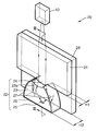
- FIG. 2A is a schematic perspective view of a near field light generating device according to an exemplary embodiment of the present invention.
- FIG. 2B is a sectional view taken along line II-II of FIG. 2A ;
- FIG. 3A illustrates a change of an effective refractive index according to the thickness of a waveguide core
- FIG. 3B illustrates a structure of a waveguide used in the simulation of FIG. 3A ;
- FIGS. 4A and 4B illustrate a lower transmission region of the near field light generating device of FIG. 2A , according to an exemplary embodiment of the present invention
- FIG. 5A is a schematic perspective view of a near field light generating device according to another exemplary embodiment of the present invention.
- FIG. 5B is a sectional view taken along line V-V of FIG. 5A ;
- FIG. 6A is a schematic perspective view of a near field light generating device according to another exemplary embodiment of the present invention.
- FIG. 6B is a sectional view taken along line VI-VI of FIG. 6A ;
- FIG. 7 is a schematic sectional view of a heat assisted magnetic recording head with the near field light generating device of FIG. 2A , according to an exemplary embodiment of the present invention.
- FIG. 2A is a schematic perspective view of a near field light generating device 20 according to an exemplary embodiment of the present invention
- FIG. 2B is a sectional view taken along line II-II of FIG. 2A .
- the near field light generating device 20 comprises a first clad layer 28 , a waveguide core 21 , a solid immersion mirror 22 formed on the first clad layer 28 , and a light source 40 . Further, a second clad layer 29 (see FIG. 7 ) may be layered on the waveguide core 21 and the solid immersion mirror 22 .
- the light source 40 is connected to one side of the waveguide core 21 and emits light to the waveguide core 21 .
- the light source 40 may be, for example, a laser diode.
- the light source 40 may abut the waveguide core 21 . That is, a light emission region of the laser diode may directly contact one side of the waveguide core 21 .
- the structure of the near field light generating device 20 may be simplified without the need for any additional optical parts between the light source 40 and the waveguide core 21 .
- the waveguide core 21 which is a transparent member of a flat panel type, transmits incident light to the solid immersion mirror 22 .
- the waveguide core 21 transmits the light via total internal reflection, and the refractive indexes of the materials of the first and second clad layers 28 and 29 should be less than the refractive index of the waveguide core 21 .
- the incident light may be near infrared light rather than visible light having a high absorption ratio.
- the second clad layer is illustrated as an air layer having a refractive index of 1.
- the solid immersion mirror 22 has a flat panel type body 23 , an upper transmission surface 24 , a lower transmission region 25 , and lateral reflection surfaces 26 and 27 , which.
- the light transmitted from the waveguide core 21 is incident on the solid immersion mirror 22 and is transmitted through the upper transmission surface 24 .
- the effective refractive index of the solid immersion mirror 22 may be greater than that of the waveguide core 21 .
- the effective refractive index is defined as a ratio of the speed of light in a free space to the speed of light progressing within the waveguide.
- the effective refractive index of the light progressing along the waveguide varies according to the mode.
- the mode acceptable in the waveguide also varies according to the shape of the waveguide.
- the effective refractive index of the flat panel type waveguide varies according to the thickness of the waveguide.
- FIG. 3A is a graph in which the effective refractive index n eff is calculated according to the thickness of a core 62 in a standard mode when a laser beam having a wavelength of 488 nm is incident on the waveguide as illustrated in FIG. 3B .
- the waveguide includes a first clad layer 61 (a flat panel type) and a core 62 (a flat panel type), and the core 61 is layered on the first clad layer 61 , with a different thickness.
- the part of the core 62 having a thin thickness H 1 corresponds to the waveguide core 21 (see FIG. 2B ) in the embodiment of FIG. 2A
- the part of the core 62 having a thickness H 2 corresponds to the solid immersion mirror 22 (see FIG. 2B ) in the embodiment of FIG. 2A .
- the first clad layer 61 can be made of SiO 2 having a refractive index of 1.413 and a thickness h of 1000 nm.
- the core 62 can be made of Si 3 N 4 having a refractive index of 2.041 and a thickness within the range of 50 nm to 450 nm.
- the effective refractive index becomes larger.
- the effective refractive index is 1.793
- the effective refractive index is 1.977.
- the near field light generating device of FIG. 2A uses the change of the effective refractive index according to the thickness of the waveguide core, as described above.
- the solid immersion mirror 22 is made of the same material as the waveguide core 21 , and is integrally formed with the waveguide core 21 so that the waveguide core 21 and the solid immersion mirror 22 are not physically separated from each other.
- the thickness H 2 of the solid immersion mirror 22 is greater that the thickness H 1 of the waveguide core 21 , so that the effective refractive index of the solid immersion mirror 22 is greater than the effective refractive index of the waveguide core 21 .
- the thickness can be changed by an etching process.
- the waveguide core 21 and the solid immersion mirror 22 are optically different from each other due to the difference between their effective refractive indexes, and the upper transmission surface 24 forms an optical boundary surface between the waveguide core 21 and the solid immersion mirror 22 .
- the upper side 23 a of the upper transmission surface is a spherical surface having negative refractive power.
- the solid immersion mirror 22 acts as a mode index lens due to the difference between the effective refractive index of the waveguide core 21 and the effective refractive index of the solid immersion mirror 22 , and the light transmitted to the upper transmission surface 24 is refracted and diverged due to the spherical surface having negative refractive power.
- the lower reflection surface 26 is disposed opposite to the upper transmission surface 24 , and is perpendicular to the first clad layer 28 where the solid immersion mirror 22 is positioned.
- the lower transmission region 25 is arranged in the center of the lower reflection surface 26 .
- the lower reflection surface 26 and the lower transmission region 25 form a part of an air bearing surface 12 (see FIG. 7 ) and face a magnetic recording medium 90 (see FIG. 7 ).
- the lower reflection surface 26 reflects the light refracted from the upper transmission surface 24 .
- the lateral reflection surfaces 27 are arranged at the sides of the solid immersion mirror 22 and have aspheric surfaces perpendicular to the first clad layer 28 where the solid immersion mirror 22 is positioned.
- the lower reflection surface 26 and the lateral reflection surfaces and 27 have a metal thin film formed thereon.
- the metal thin film may be thicker than a skin depth in order to reflect light, where a skin depth is a penetration distance of an electromagnetic wave into a medium, in this case, the metal thin film.
- a skin depth is defined by the distance at which the flux density of the electromagnetic wave decreases by a factor of 1/e (i.e. by 37%). Accordingly, the metal thin film may be thicker than a skin depth in order to prevent light leakage.
- the lateral reflection surfaces 27 re-reflect the light reflected by the lower reflection surface 26 and forms a light spot on the lower transmission region 25 .
- the size of the light spot is proportional to the wavelength of the light, which is generally concentrated, and it is inversely proportional to the number of apertures of the optical member which concentrates the light. Therefore, the solid immersion mirror 22 may have a large number of apertures. Thus, materials having large refractive indexes can be selected for the solid immersion mirror 22 . In addition, the number of apertures of the solid immersion mirror 22 can be increased by enlarging the angle between an optical axis and a beam of light having a maximum tilt angle, of the light which is re-reflected to the lower transmission region 25 and forms the light spot. Accordingly, it is possible to reduce the size of the light spot.
- the lower transmission region 25 is a through hole formed in the metal thin film on the lower reflection surface 26 .
- the diameter of the through hole can be the same as or smaller than the wavelength of the incident light.
- the lower transmission region 25 may comprise through holes 25 a and 25 a ′, and at least one or more protrusions 25 b and 25 b ′, as exemplified in FIGS. 4A and 4B , may extend thereinto.
- the protrusions 25 b and 25 b ′ are formed of a part of the metal thin film which protrudes toward the center of the through holes.
- the through holes 25 a and 25 a ′ have a substantially rectangular shape, as shown in FIGS. 4A and 4B , but may have a polygonal or round shape.
- the lower transmission region 25 has a bow-tie antenna structure in which two protrusions 25 b protrude in the longitudinal direction E from the lower reflection surface 26 , and the interval between the two protrusions 25 b is a few nm to 100 nm.
- a TE transverse electric
- the beam size of the concentrated light becomes smaller and the light intensity is strengthened, thereby making it easy to use the near field light.
- the surface plasmon excitation phenomenon by selecting a metal of high conductivity as the material of the metal thin film forming the lower reflection surface 26 . That is, as the surface plasmon excitation is generated at the metal thin film around the apertures 25 a and the metal thin film forming the protrusions 25 b by the light spot formed on the lower transmission region 25 , the intensity of the transmitted light can be strengthened more.
- the material for the metal thin film may be any one of Au, Ag, Pt, Cu, and Al.
- the near field light generating device 20 as described above can minimize optical aberration (specifically, chromatic aberration) by using a flat panel type solid immersion mirror 22 , which is a mirror optic system in which the refraction surface exists in the upper transmission surface 24 only, compared to a conventional near field light generating device using a solid immersion lens. Further, as the upper transmission surface 24 has only one refraction surface where scattering can be generated by a mode conversion within the near field light generating device 20 , there is almost no light loss except for the coupling loss from the light source 40 to the waveguide core 21 . Therefore, it is possible to increase the light efficiency of the near field light generating device 20 .
- the near field light generating device 20 does not have to include a separate collimator lens, so that it is possible to reduce the number of optical parts.
- FIG. 5A is a schematic perspective view of a near field light generating device 20 ′ according to another exemplary embodiment of the present invention
- FIG. 5B is a sectional view taken along line V-V of FIG. 5A .
- the main constitution and operation of the near field light generating device 20 ′ according to the exemplary embodiment of FIG. 5A will not be presented in detail since they are same as those of the near field light generating device according to the exemplary embodiment of FIG. 2A .
- Below will be described the differences between the near field light generating device 20 ′ of FIG. 5A and the near field light generating device of the embodiment of FIG. 2A .
- the side of the solid immersion mirror 22 and the waveguide core 21 are separated from each other, except at the upper transmission region 24 .
- the part adjacent to the outline of the solid immersion mirror 22 ′ of the waveguide core 21 is not removed.
- the lateral reflection surfaces 27 ′ are formed at the solid immersion mirror where it protrudes laterally from the waveguide core 21 .
- the lower surface of the waveguide core 21 ′ forms a part of the air bearing surface 12 (see FIG. 7 ), and the metal thin film formed on the lower reflection surface 26 ′ is extended over the lower surface of the waveguide core 21 ′.
- FIG. 6A is a schematic perspective view of a near field light generating device 30 according to another exemplary embodiment of the present invention
- FIG. 6B is a sectional view taken along line VI-VI of FIG. 6A .
- the main constitution and operation of the near field light generating device 30 according to the exemplary embodiment of FIG. 6A will not be presented in detail since they are same as those of the near field light generating devices according to the exemplary embodiments of FIGS. 2A and 5A .
- Below will be described the differences between the near field light generating device 30 of FIG. 6A and the near field light generating devices of the exemplary embodiments of FIGS. 2A and 5A .
- the near field light generating device 30 comprises a first clad layer 38 , a flat panel type waveguide core 31 and a solid immersion mirror 32 , and a light source 40 .
- the waveguide core and the solid immersion mirror are layered on the first clad layer 38 .
- the solid immersion mirror 32 is in contact with the lower side of the waveguide core 31 and includes a flat panel type body 33 having an upper transmission surface 34 , a lower transmission region 35 , a lower reflection surface 36 , and lateral reflection surfaces 37 .
- the thickness of the solid immersion mirror 32 is the same as the thickness of the waveguide core 31 , but the refractive index of the material forming the solid immersion mirror is greater than that of the material forming the waveguide core 31 .
- the upper transmission surface 34 as the boundary surface between the solid immersion mirror and the waveguide core 31 , is a curved convex surface bent convexly toward the lower reflection surface 36 ; that is, the upper transmission surface 34 has negative refractive power.
- the solid immersion mirror 32 acts as a mode index lens with respect to the waveguide.
- the light transmitted in the waveguide core 31 is incident on the solid immersion mirror via the upper transmission surface 34 .
- the light refracted from the upper transmission surface 34 is radiated toward the lower reflection surface 36 .
- FIG. 7 is a schematic sectional view of a heat assisted magnetic recording head 10 according to an exemplary embodiment of the present invention.
- the heat assisted magnetic recording head 10 comprises a substrate 11 , a near field light generating device 20 positioned at one side of the substrate 11 , and a recording unit 50 , positioned adjacently to the near field light generating device 20 .
- the recording unit 50 includes a recording pole 51 , which magnetizes a magnetic recording medium 90 ; a return pole 52 , spaced at a predetermined distance from the recording pole 51 ; a connection portion 53 , which magnetically connects the recording pole 51 and the return pole 52 ; and an induction coil 54 which induces a magnetic field around the recording pole 51 .
- the heat assisted magnetic recording head 10 may further comprise a reproduction element 55 which records and reproduces data.
- Reference numbers 56 , 57 , and 58 denote insulation layers made of non-magnetic materials, and reference number 59 denotes a shield layer which shields a stray field together with the return pole 52 .
- An end of the near field light generating device 20 , an end of the recording pole 51 , an end of the return pole 52 , and an end of the reproduction element 55 form a part of an air bearing surface 12 of the magnetic recording head 10 facing the magnetic recording medium 90 .
- the near field light generating device 20 comprises a light source 40 disposed at the substrate 11 , a first clad layer 28 , a wave guide core 21 , and a solid immersion mirror 22 , which are adjacent to the light source 40 and which are sequentially layered on the substrate 11 , and a second clad layer 29 .
- the near field light generating device 20 is described above with reference to FIGS. 2A , 5 A and 6 A.
- the heat assisted magnetic recording head 10 is spaced at a predetermined distance D from the magnetic recording medium 90 due to an air dynamic pressure generated by a relative movement with respect to the magnetic recording medium 90 .
- the heat assisted magnetic recording head 10 magnetically records data on the magnetic recording medium 90 .
- Reference number B denotes the direction of the relative movement of the magnetic recording medium 90 with respect to the magnetic recording head 10 .
- the near field light generating device 20 irradiates the near field light L having a beam size less than the diffraction limit onto the magnetic recording medium 90 . Then, as the near field light L rapidly vanishes according to the traveled distance, the distance D between the air bearing surface 12 and the magnetic recording medium 90 should be maintained within a range of about a few nm to 100 nm.
- the magnetic recording medium 90 typically comprises a base 91 , a soft magnetic material layer 92 layered on the base 91 , and a recording layer 93 layered on the soft magnetic material layer 92 and made of a hard magnetic material layer.
- the near field light L irradiated by the near field light generating device 20 locally heats the recording layer 93 to lower the coersive force thereof.
- the magnetic recording medium 90 moves in the direction B
- the locally heated region moves to the end of the recording pole 51 and is magnetized by the magnetic flux leakage generated at the end of the recording pole 51 .
- the magnetic flux leakage induced by the induction coil 54 changes the direction of the magnetic field and sequentially changes the magnetization vector of the recording layer to record information.
- the induced magnetic flux forms a closed loop which originates from the recording pole 51 , and passes the soft magnetic material layer 92 , the return pole 52 , and the connection portion 53 .
- the near field light generating device 20 and the recording unit 50 are sequentially layered on the substrate 11 .
- the order of layering of the near field light generating device 20 and the recording unit 50 may be changed.
- the magnetic recording medium moves so as to be heated by the near field light generating device before data is magnetically recorded by the recording pole.
- the heat assisted magnetic recording head 10 illustrated in FIG. 7 is a perpendicular magnetic recording system, the present invention can be applied to a horizontal magnetic recording system.
- the optical parts forming the near field light generating device can be small-sized, lightweight, and thin, and the device can be manufactured by ordinary thin film processes, together with a thin film magnetic recording head.
- the near field light generating device and the heat assisted magnetic recording head with the same of the present invention have the following exemplary effects.
- the optical parts of the near field light generating device small, lightweight and thin, and as the structure of the near field light generating is relatively simple, it is possible to simplify the process of manufacturing the near field light generating device and the heat assisted magnetic recording head with the same.
- optical aberration specifically, chromatic aberration
Abstract
Description
Claims (26)
Applications Claiming Priority (2)
| Application Number | Priority Date | Filing Date | Title |
|---|---|---|---|
| KR10-2005-0096166 | 2005-10-12 | ||
| KR1020050096166A KR100738078B1 (en) | 2005-10-12 | 2005-10-12 | Near field light generating device and heat assisted magnetic recording head employing the same |
Publications (2)
| Publication Number | Publication Date |
|---|---|
| US20070081426A1 US20070081426A1 (en) | 2007-04-12 |
| US7742368B2 true US7742368B2 (en) | 2010-06-22 |
Family
ID=37910978
Family Applications (1)
| Application Number | Title | Priority Date | Filing Date |
|---|---|---|---|
| US11/492,860 Expired - Fee Related US7742368B2 (en) | 2005-10-12 | 2006-07-26 | Near field light generating device and heat assisted magnetic recording head with the same |
Country Status (3)
| Country | Link |
|---|---|
| US (1) | US7742368B2 (en) |
| JP (1) | JP4550789B2 (en) |
| KR (1) | KR100738078B1 (en) |
Cited By (3)
| Publication number | Priority date | Publication date | Assignee | Title |
|---|---|---|---|---|
| US20080158709A1 (en) * | 2006-12-28 | 2008-07-03 | Tdk Corporation | Thermally assisted magnetic head, head gimbal assembly, and hard disk drive |
| US20100123967A1 (en) * | 2008-11-20 | 2010-05-20 | Seagate Technology Llc | Heat-assisted magnetic recording with shaped magnetic and thermal fields to minimize transition curvature |
| US8897105B1 (en) | 2013-06-04 | 2014-11-25 | Seagate Technology Llc | Solid immersion mirror with fill material between inner and outer sidewalls |
Families Citing this family (21)
| Publication number | Priority date | Publication date | Assignee | Title |
|---|---|---|---|---|
| US20030198146A1 (en) * | 2002-04-18 | 2003-10-23 | Seagate Technology Llc | Heat assisted magnetic recording head with multilayer electromagnetic radiation emission structure |
| JP2010146655A (en) * | 2008-12-19 | 2010-07-01 | Hitachi Global Storage Technologies Netherlands Bv | Optical assist magnetic recording head and manufacturing method thereof |
| US8092704B2 (en) | 2008-12-30 | 2012-01-10 | Hitachi Global Storage Technologies Netherlands B.V. | System, method and apparatus for fabricating a c-aperture or E-antenna plasmonic near field source for thermal assisted recording applications |
| US8169881B2 (en) | 2008-12-31 | 2012-05-01 | Hitachi Global Storage Technologies Netherlands B.V. | Thermally assisted recording head having recessed waveguide with near field transducer and methods of making same |
| US8325420B2 (en) * | 2009-11-24 | 2012-12-04 | Massachusetts Institute Of Technology | Annular solid immersion lenses and methods of making them |
| US8625941B1 (en) | 2010-05-20 | 2014-01-07 | Western Digital (Fremont), Llc | Broadband reflective waveguide metal gratings and their formation |
| US8456964B1 (en) | 2010-11-16 | 2013-06-04 | Western Digital (Fremont), Llc | Energy assisted magnetic recording head having a reflector for improving efficiency of the light beam |
| US8325569B1 (en) | 2011-06-27 | 2012-12-04 | Western Digital (Fremont), Llc | EAMR head having improved optical coupling efficiency |
| US8670294B1 (en) | 2012-02-17 | 2014-03-11 | Western Digital (Fremont), Llc | Systems and methods for increasing media absorption efficiency using interferometric waveguides |
| US8675455B1 (en) | 2012-02-17 | 2014-03-18 | Western Digital (Fremont), Llc | Systems and methods for controlling light phase difference in interferometric waveguides at near field transducers |
| US9286920B1 (en) | 2013-01-31 | 2016-03-15 | Western Digital (Fremont), Llc | Method for compensating for phase variations in an interferometric tapered waveguide in a heat assisted magnetic recording head |
| US9336814B1 (en) | 2013-03-12 | 2016-05-10 | Western Digital (Fremont), Llc | Inverse tapered waveguide for use in a heat assisted magnetic recording head |
| US9064527B1 (en) | 2013-04-12 | 2015-06-23 | Western Digital (Fremont), Llc | High order tapered waveguide for use in a heat assisted magnetic recording head |
| US8971159B2 (en) * | 2013-05-08 | 2015-03-03 | Seagate Technology Llc | Light delivery apparatus |
| US9064528B1 (en) | 2013-05-17 | 2015-06-23 | Western Digital Technologies, Inc. | Interferometric waveguide usable in shingled heat assisted magnetic recording in the absence of a near-field transducer |
| US8923102B1 (en) | 2013-07-16 | 2014-12-30 | Western Digital (Fremont), Llc | Optical grating coupling for interferometric waveguides in heat assisted magnetic recording heads |
| US8947985B1 (en) | 2013-07-16 | 2015-02-03 | Western Digital (Fremont), Llc | Heat assisted magnetic recording transducers having a recessed pole |
| US9142233B1 (en) | 2014-02-28 | 2015-09-22 | Western Digital (Fremont), Llc | Heat assisted magnetic recording writer having a recessed pole |
| US9190085B1 (en) | 2014-03-12 | 2015-11-17 | Western Digital (Fremont), Llc | Waveguide with reflective grating for localized energy intensity |
| US9852753B2 (en) | 2016-02-29 | 2017-12-26 | Seagate Technology Llc | Waveguide light delivery with subwavelength mirror for heat-assisted magnetic recording |
| US10748572B1 (en) * | 2018-01-09 | 2020-08-18 | Seagate Technology Llc | Waveguide having reflector for heat-assisted magnetic recording head |
Citations (22)
| Publication number | Priority date | Publication date | Assignee | Title |
|---|---|---|---|---|
| JP2000221306A (en) | 1999-02-01 | 2000-08-11 | Agency Of Ind Science & Technol | Optical coupling device |
| US6236514B1 (en) * | 1999-07-28 | 2001-05-22 | Minolta Co., Ltd. | Optical head device and near-field light emitting device |
| JP2001509938A (en) | 1997-11-22 | 2001-07-24 | サムソン エレクトロニクス カンパニー リミテッド | Focusing optical system for generating near-field, optical pickup, optical disk drive and optical disk employing the same |
| US6270696B1 (en) * | 1996-06-03 | 2001-08-07 | Terastor Corporation | Method of fabricating and integrating an optical assembly into a flying head |
| US6359850B1 (en) * | 1998-04-14 | 2002-03-19 | Samsung Electronics Co., Ltd. | Optical pickup having catadioptric objective lens |
| US6594430B1 (en) | 2000-05-11 | 2003-07-15 | Carnegie Mellon University | Solid immersion lenses for focusing collimated light in the near-field region |
| US20040001420A1 (en) * | 2002-06-28 | 2004-01-01 | Seagate Technology Llc | Heat assisted magnetic recording head with a planar waveguide |
| US6714370B2 (en) * | 2002-01-07 | 2004-03-30 | Seagate Technology Llc | Write head and method for recording information on a data storage medium |
| US20040062503A1 (en) * | 2002-09-30 | 2004-04-01 | Seagate Technology Llc | Planar waveguide for heat assisted magnetic recording |
| US20050078565A1 (en) * | 2003-10-10 | 2005-04-14 | Seagate Technology Llc | Near-field optical transducers for thermal assisted magnetic and optical data storage |
| US6885625B2 (en) * | 1998-09-18 | 2005-04-26 | Samsung Electronics Co., Ltd. | Near-field optical storage medium and optical data storage system therefor |
| US20050213884A1 (en) * | 2002-01-16 | 2005-09-29 | Ali Aldibi | Method for fabricating a tapered optical coupling into a slab waveguide |
| US20060182393A1 (en) * | 2005-02-11 | 2006-08-17 | Seagate Technology Llc | System for confined optical power delivery and enhanced optical transmission efficiency |
| US20060232869A1 (en) * | 2005-04-15 | 2006-10-19 | Amit Itagi | Apparatus for excitation, enhancement, and confinement of surface electromagnetic waves for confined optical power delivery |
| US20060256697A1 (en) * | 1998-11-27 | 2006-11-16 | Minolta Co., Ltd. | Optical head and optical head device |
| US20070070824A1 (en) * | 2005-09-28 | 2007-03-29 | Konica Minolta Holdings, Inc. | Thermal-assisted magnetic recording head and magnetic recording apparatus |
| US7227643B2 (en) * | 2002-09-26 | 2007-06-05 | Sharp Kabushiki Kaisha | Surface plasmon excitation device and microscope including the same |
| US7440383B2 (en) * | 2001-08-31 | 2008-10-21 | Sony Corporation | Optical pickup device and recording and/or reproducing apparatus |
| US7440384B2 (en) * | 2002-06-20 | 2008-10-21 | Seagate Technology Llc | Magnetic recording device for heat assisted magnetic recording |
| US20080304374A1 (en) * | 2004-07-27 | 2008-12-11 | Koninklijke Philips Electronics, N.V. | Initial Focus Optimization for an Optical Scanning Device |
| US7480214B2 (en) * | 2003-12-08 | 2009-01-20 | Seagate Technology Llc | Efficient waveguide coupler for data recording transducer |
| US20090116804A1 (en) * | 2007-11-05 | 2009-05-07 | Seagate Technology Llc | Integrated Device For Heat Assisted Magnetic Recording |
Family Cites Families (1)
| Publication number | Priority date | Publication date | Assignee | Title |
|---|---|---|---|---|
| US7106935B2 (en) | 2002-01-07 | 2006-09-12 | Seagate Technology Llc | Apparatus for focusing plasmon waves |
-
2005
- 2005-10-12 KR KR1020050096166A patent/KR100738078B1/en not_active IP Right Cessation
-
2006
- 2006-07-26 US US11/492,860 patent/US7742368B2/en not_active Expired - Fee Related
- 2006-10-04 JP JP2006273312A patent/JP4550789B2/en not_active Expired - Fee Related
Patent Citations (24)
| Publication number | Priority date | Publication date | Assignee | Title |
|---|---|---|---|---|
| US6270696B1 (en) * | 1996-06-03 | 2001-08-07 | Terastor Corporation | Method of fabricating and integrating an optical assembly into a flying head |
| JP2001509938A (en) | 1997-11-22 | 2001-07-24 | サムソン エレクトロニクス カンパニー リミテッド | Focusing optical system for generating near-field, optical pickup, optical disk drive and optical disk employing the same |
| US6359850B1 (en) * | 1998-04-14 | 2002-03-19 | Samsung Electronics Co., Ltd. | Optical pickup having catadioptric objective lens |
| US7362693B2 (en) * | 1998-09-18 | 2008-04-22 | Samsung Electronics Co., Ltd. | Near-field optical storage medium and optical data storage system therefor |
| US6885625B2 (en) * | 1998-09-18 | 2005-04-26 | Samsung Electronics Co., Ltd. | Near-field optical storage medium and optical data storage system therefor |
| US20060256697A1 (en) * | 1998-11-27 | 2006-11-16 | Minolta Co., Ltd. | Optical head and optical head device |
| JP2000221306A (en) | 1999-02-01 | 2000-08-11 | Agency Of Ind Science & Technol | Optical coupling device |
| US6236514B1 (en) * | 1999-07-28 | 2001-05-22 | Minolta Co., Ltd. | Optical head device and near-field light emitting device |
| US6594430B1 (en) | 2000-05-11 | 2003-07-15 | Carnegie Mellon University | Solid immersion lenses for focusing collimated light in the near-field region |
| US7440383B2 (en) * | 2001-08-31 | 2008-10-21 | Sony Corporation | Optical pickup device and recording and/or reproducing apparatus |
| US6714370B2 (en) * | 2002-01-07 | 2004-03-30 | Seagate Technology Llc | Write head and method for recording information on a data storage medium |
| US20050213884A1 (en) * | 2002-01-16 | 2005-09-29 | Ali Aldibi | Method for fabricating a tapered optical coupling into a slab waveguide |
| US7440384B2 (en) * | 2002-06-20 | 2008-10-21 | Seagate Technology Llc | Magnetic recording device for heat assisted magnetic recording |
| US6944112B2 (en) * | 2002-06-28 | 2005-09-13 | Seagate Technology Llc | Heat assisted magnetic recording head with a planar waveguide |
| US20040001420A1 (en) * | 2002-06-28 | 2004-01-01 | Seagate Technology Llc | Heat assisted magnetic recording head with a planar waveguide |
| US7227643B2 (en) * | 2002-09-26 | 2007-06-05 | Sharp Kabushiki Kaisha | Surface plasmon excitation device and microscope including the same |
| US20040062503A1 (en) * | 2002-09-30 | 2004-04-01 | Seagate Technology Llc | Planar waveguide for heat assisted magnetic recording |
| US20050078565A1 (en) * | 2003-10-10 | 2005-04-14 | Seagate Technology Llc | Near-field optical transducers for thermal assisted magnetic and optical data storage |
| US7480214B2 (en) * | 2003-12-08 | 2009-01-20 | Seagate Technology Llc | Efficient waveguide coupler for data recording transducer |
| US20080304374A1 (en) * | 2004-07-27 | 2008-12-11 | Koninklijke Philips Electronics, N.V. | Initial Focus Optimization for an Optical Scanning Device |
| US20060182393A1 (en) * | 2005-02-11 | 2006-08-17 | Seagate Technology Llc | System for confined optical power delivery and enhanced optical transmission efficiency |
| US20060232869A1 (en) * | 2005-04-15 | 2006-10-19 | Amit Itagi | Apparatus for excitation, enhancement, and confinement of surface electromagnetic waves for confined optical power delivery |
| US20070070824A1 (en) * | 2005-09-28 | 2007-03-29 | Konica Minolta Holdings, Inc. | Thermal-assisted magnetic recording head and magnetic recording apparatus |
| US20090116804A1 (en) * | 2007-11-05 | 2009-05-07 | Seagate Technology Llc | Integrated Device For Heat Assisted Magnetic Recording |
Non-Patent Citations (1)
| Title |
|---|
| Xiaolei Shi, "A Nano-aperture with 1000X Power Throughput Enhancement for Very Small Aperture Laser System (VSAL)", Proceedings of SPIE vol. 4342 (2002), pp. 320-327. * |
Cited By (8)
| Publication number | Priority date | Publication date | Assignee | Title |
|---|---|---|---|---|
| US20080158709A1 (en) * | 2006-12-28 | 2008-07-03 | Tdk Corporation | Thermally assisted magnetic head, head gimbal assembly, and hard disk drive |
| US7876646B2 (en) * | 2006-12-28 | 2011-01-25 | Tdk Corporation | Thermally assisted magnetic head, head gimbal assembly, and hard disk drive |
| US20100123967A1 (en) * | 2008-11-20 | 2010-05-20 | Seagate Technology Llc | Heat-assisted magnetic recording with shaped magnetic and thermal fields to minimize transition curvature |
| US7965464B2 (en) * | 2008-11-20 | 2011-06-21 | Seagate Technology Llc | Heat-assisted magnetic recording with shaped magnetic and thermal fields |
| US20110211428A1 (en) * | 2008-11-20 | 2011-09-01 | Seagate Technology Llc | Heat-assisted magnetic recording with shaped magnetic and thermal fields to minimize transition curvature |
| US8159769B2 (en) | 2008-11-20 | 2012-04-17 | Seagate Technology Llc | Heat-assisted magnetic recording with shaped magnetic and thermal fields to minimize transition curvature |
| US8897105B1 (en) | 2013-06-04 | 2014-11-25 | Seagate Technology Llc | Solid immersion mirror with fill material between inner and outer sidewalls |
| US9070385B2 (en) | 2013-06-04 | 2015-06-30 | Seagate Technology Llc | Solid immersion mirror with fill material between inner and outer sidewalls |
Also Published As
| Publication number | Publication date |
|---|---|
| JP2007109373A (en) | 2007-04-26 |
| US20070081426A1 (en) | 2007-04-12 |
| KR20070040634A (en) | 2007-04-17 |
| JP4550789B2 (en) | 2010-09-22 |
| KR100738078B1 (en) | 2007-07-12 |
Similar Documents
| Publication | Publication Date | Title |
|---|---|---|
| US7742368B2 (en) | Near field light generating device and heat assisted magnetic recording head with the same | |
| JP4800889B2 (en) | Heat-assisted magnetic recording head and method for manufacturing the same | |
| US8456964B1 (en) | Energy assisted magnetic recording head having a reflector for improving efficiency of the light beam | |
| US6795630B2 (en) | Apparatus and method for producing a small spot of optical energy | |
| US7272079B2 (en) | Transducer for heat assisted magnetic recording | |
| US7412143B2 (en) | Heat assisted magnetic recording with heat profile shaping | |
| US7027700B2 (en) | Planar waveguide for heat assisted magnetic recording | |
| KR100718146B1 (en) | Heat assisted magnetic recording head | |
| US6944112B2 (en) | Heat assisted magnetic recording head with a planar waveguide | |
| JP5777585B2 (en) | Apparatus, method, and system with waveguide | |
| US7330404B2 (en) | Near-field optical transducers for thermal assisted magnetic and optical data storage | |
| US8325569B1 (en) | EAMR head having improved optical coupling efficiency | |
| US7609591B2 (en) | Heat-assisted magnetic recording head | |
| US8456966B1 (en) | Method and system for enhancing optical efficiency for an EAMR head | |
| JP5695885B2 (en) | Method for directing light from waveguides and light sources | |
| US9251819B2 (en) | Mode converter coupling energy at a high-order transverse electric mode to a plasmonic transducer | |
| CN101097748B (en) | Near-field optical transducers having a tilted metallic pin | |
| US7688684B2 (en) | Heat-assisted magnetic recording head and recording apparatus including the same | |
| EP1821288B1 (en) | Magnetic head and information storage apparatus | |
| WO2005045815A1 (en) | Near-field optical transducers for thermal assisted magnetic and optical data storage |
Legal Events
| Date | Code | Title | Description |
|---|---|---|---|
| AS | Assignment |
Owner name: SAMSUNG ELECTRONICS CO., LTD.,KOREA, REPUBLIC OF Free format text: ASSIGNMENT OF ASSIGNORS INTEREST;ASSIGNORS:LEE, MYUNG-BOK;SOHN, JIN-SEUNG;SUH, SUNG-DONG;AND OTHERS;REEL/FRAME:018131/0978 Effective date: 20060721 Owner name: SAMSUNG ELECTRONICS CO., LTD., KOREA, REPUBLIC OF Free format text: ASSIGNMENT OF ASSIGNORS INTEREST;ASSIGNORS:LEE, MYUNG-BOK;SOHN, JIN-SEUNG;SUH, SUNG-DONG;AND OTHERS;REEL/FRAME:018131/0978 Effective date: 20060721 |
|
| STCF | Information on status: patent grant |
Free format text: PATENTED CASE |
|
| AS | Assignment |
Owner name: SEAGATE TECHNOLOGY INTERNATIONAL, CAYMAN ISLANDS Free format text: ASSIGNMENT OF ASSIGNORS INTEREST;ASSIGNOR:SAMSUNG ELECTRONICS CO., LTD.;REEL/FRAME:028153/0689 Effective date: 20111219 |
|
| FPAY | Fee payment |
Year of fee payment: 4 |
|
| AS | Assignment |
Owner name: SAMSUNG ELECTRONICS CO., LTD., KOREA, REPUBLIC OF Free format text: CORRECTIVE ASSIGNMENT TO CORRECT THE REMOVE ERRONEOUSLY FILED NO. 7255478 FROM SCHEDULE PREVIOUSLY RECORDED AT REEL: 028153 FRAME: 0689. ASSIGNOR(S) HEREBY CONFIRMS THE ASSIGNMENT;ASSIGNOR:SAMSUNG ELECTRONICS CO., LTD.;REEL/FRAME:040001/0920 Effective date: 20160720 |
|
| MAFP | Maintenance fee payment |
Free format text: PAYMENT OF MAINTENANCE FEE, 8TH YEAR, LARGE ENTITY (ORIGINAL EVENT CODE: M1552) Year of fee payment: 8 |
|
| FEPP | Fee payment procedure |
Free format text: MAINTENANCE FEE REMINDER MAILED (ORIGINAL EVENT CODE: REM.); ENTITY STATUS OF PATENT OWNER: LARGE ENTITY |
|
| LAPS | Lapse for failure to pay maintenance fees |
Free format text: PATENT EXPIRED FOR FAILURE TO PAY MAINTENANCE FEES (ORIGINAL EVENT CODE: EXP.); ENTITY STATUS OF PATENT OWNER: LARGE ENTITY |
|
| STCH | Information on status: patent discontinuation |
Free format text: PATENT EXPIRED DUE TO NONPAYMENT OF MAINTENANCE FEES UNDER 37 CFR 1.362 |
|
| FP | Lapsed due to failure to pay maintenance fee |
Effective date: 20220622 |