US7743348B2 - Using physical objects to adjust attributes of an interactive display application - Google Patents
Using physical objects to adjust attributes of an interactive display application Download PDFInfo
- Publication number
- US7743348B2 US7743348B2 US10/883,515 US88351504A US7743348B2 US 7743348 B2 US7743348 B2 US 7743348B2 US 88351504 A US88351504 A US 88351504A US 7743348 B2 US7743348 B2 US 7743348B2
- Authority
- US
- United States
- Prior art keywords
- location
- display surface
- interactive display
- primary
- image
- Prior art date
- Legal status (The legal status is an assumption and is not a legal conclusion. Google has not performed a legal analysis and makes no representation as to the accuracy of the status listed.)
- Expired - Fee Related, expires
Links
Images


Classifications
-
- G—PHYSICS
- G06—COMPUTING; CALCULATING OR COUNTING
- G06F—ELECTRIC DIGITAL DATA PROCESSING
- G06F3/00—Input arrangements for transferring data to be processed into a form capable of being handled by the computer; Output arrangements for transferring data from processing unit to output unit, e.g. interface arrangements
- G06F3/01—Input arrangements or combined input and output arrangements for interaction between user and computer
- G06F3/048—Interaction techniques based on graphical user interfaces [GUI]
- G06F3/0487—Interaction techniques based on graphical user interfaces [GUI] using specific features provided by the input device, e.g. functions controlled by the rotation of a mouse with dual sensing arrangements, or of the nature of the input device, e.g. tap gestures based on pressure sensed by a digitiser
- G06F3/0488—Interaction techniques based on graphical user interfaces [GUI] using specific features provided by the input device, e.g. functions controlled by the rotation of a mouse with dual sensing arrangements, or of the nature of the input device, e.g. tap gestures based on pressure sensed by a digitiser using a touch-screen or digitiser, e.g. input of commands through traced gestures
-
- G—PHYSICS
- G06—COMPUTING; CALCULATING OR COUNTING
- G06F—ELECTRIC DIGITAL DATA PROCESSING
- G06F3/00—Input arrangements for transferring data to be processed into a form capable of being handled by the computer; Output arrangements for transferring data from processing unit to output unit, e.g. interface arrangements
- G06F3/01—Input arrangements or combined input and output arrangements for interaction between user and computer
- G06F3/03—Arrangements for converting the position or the displacement of a member into a coded form
- G06F3/041—Digitisers, e.g. for touch screens or touch pads, characterised by the transducing means
- G06F3/042—Digitisers, e.g. for touch screens or touch pads, characterised by the transducing means by opto-electronic means
- G06F3/0421—Digitisers, e.g. for touch screens or touch pads, characterised by the transducing means by opto-electronic means by interrupting or reflecting a light beam, e.g. optical touch-screen
-
- G—PHYSICS
- G06—COMPUTING; CALCULATING OR COUNTING
- G06F—ELECTRIC DIGITAL DATA PROCESSING
- G06F3/00—Input arrangements for transferring data to be processed into a form capable of being handled by the computer; Output arrangements for transferring data from processing unit to output unit, e.g. interface arrangements
- G06F3/01—Input arrangements or combined input and output arrangements for interaction between user and computer
- G06F3/048—Interaction techniques based on graphical user interfaces [GUI]
- G06F3/0481—Interaction techniques based on graphical user interfaces [GUI] based on specific properties of the displayed interaction object or a metaphor-based environment, e.g. interaction with desktop elements like windows or icons, or assisted by a cursor's changing behaviour or appearance
- G06F3/0482—Interaction with lists of selectable items, e.g. menus
-
- G—PHYSICS
- G06—COMPUTING; CALCULATING OR COUNTING
- G06F—ELECTRIC DIGITAL DATA PROCESSING
- G06F3/00—Input arrangements for transferring data to be processed into a form capable of being handled by the computer; Output arrangements for transferring data from processing unit to output unit, e.g. interface arrangements
- G06F3/01—Input arrangements or combined input and output arrangements for interaction between user and computer
- G06F3/048—Interaction techniques based on graphical user interfaces [GUI]
- G06F3/0484—Interaction techniques based on graphical user interfaces [GUI] for the control of specific functions or operations, e.g. selecting or manipulating an object, an image or a displayed text element, setting a parameter value or selecting a range
- G06F3/04845—Interaction techniques based on graphical user interfaces [GUI] for the control of specific functions or operations, e.g. selecting or manipulating an object, an image or a displayed text element, setting a parameter value or selecting a range for image manipulation, e.g. dragging, rotation, expansion or change of colour
-
- G—PHYSICS
- G06—COMPUTING; CALCULATING OR COUNTING
- G06F—ELECTRIC DIGITAL DATA PROCESSING
- G06F2203/00—Indexing scheme relating to G06F3/00 - G06F3/048
- G06F2203/048—Indexing scheme relating to G06F3/048
- G06F2203/04806—Zoom, i.e. interaction techniques or interactors for controlling the zooming operation
Definitions
- the present invention generally pertains to a computing system having an interactive display surface operable to detect physical objects placed adjacent to the interactive display surface, and more specifically, to detect positions and movements of the physical objects to provide input to change one or more attributes of an application being executed by the computing system.
- PCs Personal computers
- PCs have become increasingly more powerful in many different respects.
- One example of the increased power of computers is in their tremendously improved graphics capabilities. While early PCs were limited to four colors and pixilated low resolution displays, contemporary computers provide colorful, high-resolution graphics that are more than suitable for viewing digital photographs or watching movies as well as enabling display of fast moving virtual images in games and other applications.
- the metaDESK includes a generally planar graphical surface that not only displays computing system text and graphic output, but also receives user input by responding to an object placed against the graphical surface.
- the combined object-responsive and display capability of the graphical surface of the metaDESK is facilitated using infrared (IR) light, an IR camera, a video camera, a video projector, and mirrors disposed beneath the surface of the metaDESK.
- the mirrors reflect the graphical image projected by the projector onto the underside of the graphical display surface to provide images that are visible to a user from above the graphical display surface.
- the IR camera can detect IR light reflected from the undersurface of an object placed on the graphical surface.
- the metaDESK can respond to the contemporaneous placement and movement of the object on the display surface to carryout a predefined function, such as displaying and moving a map of the MIT campus.
- a predefined function such as displaying and moving a map of the MIT campus.
- Such systems are generally limited to responding to a specific object in a predefined manner.
- a user should be able to engage a computer system, such as by responding to prompts, issuing commands, or changing attributes, without having to use a keyboard or make use of any specific physical objects.
- a personal computer it would clearly be desirable to interact with images or other graphical information presented by a computing system on a display screen by using ordinary objects or even one's own hands and fingers.
- One of the advantages of the present invention is that it provides a convenient, natural, and intuitive manner for a user to interact with a computer system having an interactive display surface.
- a user responds to images or other attributes of applications presented on a display by engaging a keyboard, a pointing device, or another input device that is separate and removed from the display.
- the present invention enables a user to employ physical objects, such as fingers and thumbs of the user's hand, to modify images presented on the interactive display surface.
- a user can use digits on the user's hands or other physical objects to modify attributes of an application executing on the computer system associated with the interactive display surface.
- a user can provide input to the computer system by interacting directly with the output of the computer system to provide the input.
- the present invention is particularly useful in resizing or cropping images that are rectangular, it should be understood that the user's fingers or hands or other physical objects can be applied in resizing or cropping virtual entities other than rectangular images.
- the user can interact with irregularly-shaped virtually entities or with three-dimensional entities to resize or crop them, just as discussed below in regard to resizing or cropping images.
- This application includes at least one attribute that can be changed during execution of the application.
- a primary location is determined where a primary physical object is positioned adjacent to the interactive display surface.
- An additional location is determined where an additional physical object is positioned adjacent to the interactive display surface.
- the attribute is associated with the primary location and the additional location.
- a change in position of at least one of the primary location and the additional location is determined, and the attribute is adjusted based on the change in position of at least one of the primary location and the additional location.
- the attributes of the application can thus be adjusted, for example, by touching the interactive display surface with one's fingers or other objects.
- the primary location, the additional location, and changes in the locations are determined using IR light.
- IR light is transmitted through the interactive display surface toward a face of the interactive display surface.
- the primary physical object and the secondary physical object are disposed adjacent to an opposite side of the interactive display surface.
- the primary and additional locations thus are determined by sensing IR light reflected from the primary physical object when the primary and additional physical objects, respectively, are positioned adjacent to the interactive display surface.
- Changes in the position of the primary and additional locations are determined by sensing changes in the locations of the primary physical object and the secondary physical object, respectively.
- at least one of the primary physical object and the additional physical object is a digit on one of a user's hands.
- the attribute includes a size of an image displayed on the interactive display surface.
- the size of the image displayed is changed first by determining that either the primary location or the secondary location is either disposed on a boundary of the image or within the image and that the primary and additional locations are either generally vertically aligned or horizontally aligned with each other.
- the image is resized by moving at least its opposite boundaries as defined by the primary location and the additional location.
- An aspect ratio of the image may be either preserved or changed relative to changes of the boundaries of the image.
- the invention also enables the portion of the image that is displayed to be readily changed, i.e., by cropping the image, in response to objects that are positioned on the interactive display surface.
- Cropping the image displayed begins with determining that the primary location and the additional location are neither in vertical nor horizontal alignment with each other.
- a new image boundary is then determined based upon the positions of the primary location and the additional location, so that its diagonally opposite corners correspond to the positions of the primary location and the additional location, and all but the portion of the image bounded by the new image boundary is deleted from the display surface.
- the present invention can be employed for changing an attribute relating to a property selected from a property selection range displayed adjacent to the primary location.
- the property selection range such as a menu, includes a range of property choices arrayed across positions encompassed by the property selection range.
- the additional location is associated with a property selected from the range of property choices that is closest to the additional location.
- the attribute is then adjusted in accordance with the property selected.
- the size of the property selection range may be selectively adjusted by the user.
- the size is changed by detecting a secondary location adjacent to the interactive display surface where a second physical object is placed.
- the size of the property selection range is then adjusted to generally fit the space defined by the primary location and the secondary location. For example, if the user uses a thumb and a finger of one of the user's hands as the first and second physical objects, the property selection range may be fit to the space defined by the user's thumb and finger. The user might then make a selection from the property selection range so defined by using a finger from the user's other hand.
- a property selection range may also be used to invoke subsidiary property selection ranges or sub-menus.
- the property selection range can include a range of property choices arrayed across positions encompassed by the property selection range.
- the additional location is associated with a property selected among the range of property choices.
- An additional property selection range associated with the selected property is presented, providing an additional array of choices.
- An additional property selected is determined by associating an additional property choice closest to a changed additional location of the additional physical object. The corresponding attribute is then adjusted in accordance with the selection.
- FIG. 1 is a functional block diagram of a generally conventional computing device or personal computer (PC) that is suitable for use with an interactive display surface in practicing the present invention
- FIG. 2 is a cross-sectional view illustrating internal components of an interactive display surface in the form of an interactive table that includes an integral PC;
- FIG. 3 is an isometric view of an embodiment in which the interactive table is connected to an external PC
- FIGS. 4A-4I illustrate an image being resized on the interactive display surface by a user's fingers, while preserving the aspect ratio of the image
- FIGS. 5A-5D illustrate an image being resized on the interactive display surface in one or two dimensions by a user's fingers, depending on where the user's fingers engage the image;
- FIGS. 6A-6E illustrate an image being cropped on the interactive display surface, based upon the positions where a user's fingers touch the interactive display surface
- FIGS. 7A-7C illustrate an image being resized on the interactive display surface using physical objects instead of or in addition to a user's fingers
- FIGS. 8A-8F illustrate an attribute of an application being changed by a user's fingers manipulating a property selection range presented on the interactive display surface
- FIGS. 9A-9D illustrate a property selection range being presented and resized in accordance with placement of a user's fingers on the interactive display surface
- FIGS. 10A-10D illustrate a perspective view of a user's hand engaging an interactive display surface to position, size, and engage a property selection range
- FIGS. 11A-11B illustrate a property selection range having at least one property choice associated with an additional property selection range being manipulated by a user's fingers
- FIG. 12 is a flow diagram illustrating the logical steps regarding manipulation of an image or other virtual entity using one or more physical objects
- FIG. 13A is a flow diagram illustrating the logical steps for manipulating an image to change its size according to the present invention
- FIG. 13B is a flow diagram illustrating the logical steps for cropping an image according to the present invention.
- FIG. 14 is a flow diagram illustrating the logical steps for adjusting an attribute of an application according to an embodiment of the present invention.
- the system includes a general purpose computing device in the form of a conventional PC 20 , provided with a processing unit 21 , a system memory 22 , and a system bus 23 .
- the system bus couples various system components including the system memory to processing unit 21 and may be any of several types of bus structures, including a memory bus or memory controller, a peripheral bus, and a local bus using any of a variety of bus architectures.
- the system memory includes read only memory (ROM) 24 and random access memory (RAM) 25 .
- ROM read only memory
- RAM random access memory
- PC 20 further includes a hard disk drive 27 for reading from and writing to a hard disk (not shown), a magnetic disk drive 28 for reading from or writing to a removable magnetic disk 29 , and an optical disk drive 30 for reading from or writing to a removable optical disk 31 , such as a compact disk-read only memory (CD-ROM) or other optical media.
- Hard disk drive 27 , magnetic disk drive 28 , and optical disk drive 30 are connected to system bus 23 by a hard disk drive interface 32 , a magnetic disk drive interface 33 , and an optical disk drive interface 34 , respectively.
- the drives and their associated computer readable media provide nonvolatile storage of computer readable machine instructions, data structures, program modules, and other data for PC 20 .
- a number of program modules may be stored on the hard disk, magnetic disk 29 , optical disk 31 , ROM 24 , or RAM 25 , including an operating system 35 , one or more application programs 36 , other program modules 37 , and program data 38 .
- a user may enter commands and information in PC 20 and provide control input through input devices, such as a keyboard 40 and a pointing device 42 .
- Pointing device 42 may include a mouse, stylus, wireless remote control, or other pointer, but in connection with the present invention, such conventional pointing devices may be omitted, since the user can employ the interactive display for input and control.
- the term “mouse” is intended to encompass virtually any pointing device that is useful for controlling the position of a cursor on the screen.
- I/O input/output
- Other input devices may include a microphone, joystick, haptic joystick, yoke, foot pedals, game pad, satellite dish, scanner, or the like.
- I/O interface 46 input/output devices
- the term I/O interface is intended to encompass each interface specifically used for a serial port, a parallel port, a game port, a keyboard port, and/or a universal serial bus (USB).
- System bus 23 is also connected to a camera interface 59 , which is coupled to an interactive display 60 to receive signals from a digital video camera that is included therein, as discussed below.
- the digital video camera may be instead coupled to an appropriate serial I/O port, such as to a USB version 2.0 port.
- a monitor 47 can be connected to system bus 23 via an appropriate interface, such as a video adapter 48 ; however, the interactive display table of the present invention can provide a much richer display and interact with the user for input of information and control of software applications and is therefore preferably coupled to the video adaptor.
- PCs are often coupled to other peripheral output devices (not shown), such as speakers (through a sound card or other audio interface—not shown) and printers.
- the present invention may be practiced using a single computing device, although PC 20 can also operate in a networked environment using logical connections to one or more remote computers, such as a remote computer 49 .
- Remote computer 49 may be another PC, a server (which is typically generally configured much like PC 20 ), a router, a network PC, a peer device, or a satellite or other common network node, and typically includes many or all of the elements described above in connection with PC 20 , although only an external memory storage device 50 has been illustrated in FIG. 1 .
- the logical connections depicted in FIG. 1 include a local area network (LAN) 51 and a wide area network (WAN) 52 .
- LAN local area network
- WAN wide area network
- Such networking environments are common in offices, enterprise wide computer networks, intranets, and the Internet.
- PC 20 When used in a LAN networking environment, PC 20 is connected to LAN 51 through a network interface or adapter 53 .
- PC 20 When used in a WAN networking environment, PC 20 typically includes a modem 54 , or other means such as a cable modem, Digital Subscriber Line (DSL) interface, or an Integrated Service Digital Network (ISDN) interface for establishing communications over WAN 52 , e.g., over the Internet.
- Modem 54 which may be internal or external, is connected to the system bus 23 or coupled to the bus via I/O device interface 46 , i.e., through a serial port.
- program modules, or portions thereof, used by PC 20 may be stored in the remote memory storage device. It will be appreciated that the network connections shown are exemplary, and other means of establishing a communications link between the computers may be used, such as wireless communication and wide band network links.
- an exemplary interactive display table 60 is shown that includes PC 20 within a frame 62 and which serves as both an optical input and video display device for the computer.
- rays of light used for displaying text and graphic images are generally illustrated using dotted lines, while rays of infrared (IR) light used for sensing objects on or just above a display surface 64 a of the interactive display table are illustrated using dash lines.
- Display surface 64 a is set within an upper surface 64 of the interactive display table. The perimeter of the table surface is useful for supporting a user's arms or other objects, including objects that may be used to interact with the graphic images or virtual environment being displayed on display surface 64 a.
- IR light sources 66 preferably comprise a plurality of IR light emitting diodes (LEDs) and are mounted on the interior side of frame 62 .
- the IR light that is produced by IR light sources 66 is directed upwardly toward the underside of display surface 64 a , as indicated by dash lines 78 a , 78 b , and 78 c .
- the IR light from IR light sources 66 is reflected from any objects that are atop or proximate to the display surface after passing through a translucent layer 64 b of the table, comprising a sheet of vellum or other suitable translucent material with light diffusing properties.
- IR source 66 Although only one IR source 66 is shown, it will be appreciated that a plurality of such IR sources may be mounted at spaced-apart locations around the interior sides of frame 62 to prove an even illumination of display surface 64 a .
- the infrared light produced by the IR sources may:
- Objects above display surface 64 a include a “touch” object 76 a that rests atop the display surface and a “hover” object 76 b that is close to but not in actual contact with the display surface.
- a “touch” object 76 a that rests atop the display surface
- a “hover” object 76 b that is close to but not in actual contact with the display surface.
- a digital video camera 68 is mounted to frame 62 below display surface 64 a in a position appropriate to receive IR light that is reflected from any touch object or hover object disposed above display surface 64 a .
- Digital video camera 68 is equipped with an IR pass filter 86 a that transmits only IR light and blocks ambient visible light traveling through display surface 64 a along dotted line 84 a .
- a baffle 79 is disposed between IR source 66 and the digital video camera to prevent IR light that is directly emitted from the IR source from entering the digital video camera, since it is preferable that this digital video camera should produce an output signal that is only responsive to the IR light reflected from objects that are a short distance above or in contact with display surface 64 a and corresponds to an image of IR light reflected from objects on or above the display surface. It will be apparent that digital video camera 68 will also respond to any IR light included in the ambient light that passes through display surface 64 a from above and into the interior of the interactive display (e.g., ambient IR light that also travels along the path indicated by dotted line 84 a ).
- IR light reflected from objects on or above the table surface may be:
- Translucent layer 64 b diffuses both incident and reflected IR light.
- “hover” objects that are closer to display surface 64 a will reflect more IR light back to digital video camera 68 than objects of the same reflectivity that are farther away from the display surface.
- Digital video camera 68 senses the IR light reflected from “touch” and “hover” objects within its imaging field and produces a digital signal corresponding to images of the reflected IR light that is input to PC 20 for processing to determine a location of each such object, and optionally, the size, orientation, and shape of the object.
- a portion of an object such as a user's forearm
- another portion such as the user's finger
- an object may include an IR light reflective pattern or coded identifier (e.g., a bar code) on its bottom surface that is specific to that object or to a class of related objects of which that object is a member.
- the imaging signal from digital video camera 68 can also be used for detecting each such specific object, as well as determining its orientation, based on the IR light reflected from its reflective pattern, in accord with the present invention. The logical steps implemented to carry out this function are explained below.
- PC 20 may be integral to interactive display table 60 as shown in FIG. 2 , or alternatively, may instead be external to the interactive display table, as shown in the embodiment of FIG. 3 .
- an interactive display table 60 ′ is connected through a data cable 63 to an external PC 20 (which includes optional monitor 47 , as mentioned above).
- an external PC 20 which includes optional monitor 47 , as mentioned above.
- a set of orthogonal X and Y axes are associated with display surface 64 a , as well as an origin indicated by “0.” While not specifically shown, it will be appreciated that a plurality of coordinate locations along each orthogonal axis can be employed to indicate any location on display surface 64 a.
- the interactive display table comprises an input/output device.
- Power for the interactive display table is provided through a power lead 61 , which is coupled to a conventional alternating current (AC) line source (not shown).
- Data cable 63 which connects to interactive display table 60 ′, can be coupled to a USB 2.0 port, an Institute of Electrical and Electronics Engineers (IEEE) 1394 (or Firewire) port, or an Ethernet port on PC 20 .
- IEEE Institute of Electrical and Electronics Engineers
- the interactive display table might also be connected to a computing device such as PC 20 via such a high speed wireless connection, or via some other appropriate wired or wireless data communication link.
- PC 20 executes algorithms for processing the digital images from digital video camera 68 and executes software applications that are designed to use the more intuitive user interface functionality of interactive display table 60 to good advantage, as well as executing other software applications that are not specifically designed to make use of such functionality, but can still make good use of the input and output capability of the interactive display table.
- the interactive display can be coupled to an external computing device, but include an internal computing device for doing image processing and other tasks that would then not be done by the external PC.
- An important and powerful feature of the interactive display table is its ability to display graphic images or a virtual environment for games or other software applications and to enable an interaction between the graphic image or virtual environment visible on display surface 64 a and objects that are resting atop the display surface, such as an object 76 a , or are hovering just above it, such as an object 76 b . It is the ability of the interactive display table to visually detect such objects, as well as the user's finger or other object being moved by the user that greatly facilities this rich interaction.
- interactive display table 60 includes a video projector 70 that is used to display graphic images, a virtual environment, or text information on display surface 64 a .
- the video projector is preferably of a liquid crystal display (LCD) or digital light processor (DLP) type, or a liquid crystal on silicon (LCoS) display type, with a resolution of at least 640 ⁇ 480 pixels.
- An IR cut filter 86 b is mounted in front of the projector lens of video projector 70 to prevent IR light emitted by the video projector from entering the interior of the interactive display table where the IR light might interfere with the IR light reflected from object(s) on or above display surface 64 a .
- a first mirror assembly 72 a directs projected light traveling from the projector lens along dotted path 82 a through a transparent opening 90 a in frame 62 , so that the projected light is incident on a second mirror assembly 72 b .
- Second mirror assembly 72 b reflects the projected light along a path 82 b onto translucent layer 64 b , which is at the focal point of the projector lens, so that the projected image is visible and in focus on display surface 64 a for viewing.
- Alignment devices 74 a and 74 b are provided and include threaded rods and rotatable adjustment nuts 74 c for adjusting the angles of the first and second mirror assemblies to ensure that the image projected onto the display surface is aligned with the display surface.
- the use of these two mirror assemblies provides a longer path between projector 70 and translucent layer 64 b , and more importantly, helps in achieving a desired size and shape of the interactive display table, so that the interactive display table is not too large and is sized and shaped so as to enable the user to sit comfortably next to it.
- a user resizes an image on an interactive display surface 400 by using physical objects to manipulate the image.
- the present invention is also applicable to manipulating other virtual entities, including irregularly shaped virtual entities and even three-dimensional shapes that are displayed on the interactive display surface.
- any type of physical object can be employed instead of the user's digits or hands.
- the user touches the area of interactive display surface 400 where the image is presented with the user's fingers, and, by positioning or moving the user's fingers, changes how the image is displayed.
- the user can reposition, resize, rotate, or crop the image presented on interactive display surface 400 without using a keyboard, pointing device, or any other input device other than the fingers touched to interactive display surface 400 .
- interactive display surface 400 presents an unaltered image 402 a .
- Image 402 a includes a boundary 404 a encompassing content 406 a .
- the process of altering the image begins with a user applying a physical object to interactive display surface 400 .
- the user touches a finger 412 a of user's hand 410 a either to boundary 404 a of image 402 a , at a first edge 414 a or within the boundary of the image.
- the user may initiate an editing sequence by double tapping with the finger on the interactive display surface, or the use of two physical objects touching the interactive display surface may initiate the editing sequence.
- the image will move over the interactive display surface in a corresponding direction and extent, and the relative position of the finger of object within the image will remain constant. Touching the interactive display surface with a second finger or object indicates a user's desire to resize, rotate, or crop the image, depending upon the disposition and motion of the second finger or object relative to the finger or object that first touched the interactive display surface, as described below in further detail.
- interactive display surface 400 signals that image 402 a is about to be changed by generating a highlighted outline 416 a around image 402 a .
- Feedback in response to the user's action in the form of highlighted outline 416 a or some other appropriate feedback confirms to the user that the user is initiating a function, so that the user is warned if inadvertently initiating a function the user has not intended.
- the user proceeds with resizing image 402 a by touching the interactive display surface outside the boundary of the image at a second point 418 a with a second finger 422 a of the user's other hand 420 a .
- second point 418 a is horizontally aligned with first point 414 a , thereby indicating the user desires to resize or scale image 402 a .
- first point 414 a and second point 418 a can alternatively be vertically aligned to indicate that the user wants to resize the image.
- the interactive display surface detects and confirms the proposed resizing of the image in the direction indicated by an arrow 424 by displaying an enlarged highlighted outline 416 b that shows the size of the enlarged image that will result from the user's actions.
- interactive display surface 400 could alternatively immediately resize image 402 a , rather than only show the change in size using highlighted outline 416 b .
- highlighted outline 416 b need not be enlarged, but could be left to show the original size of image 402 a as the image is changed in size in response to the user's action.
- highlighted outline 416 b indicates that as image 402 a is enlarged, its aspect ratio will be preserved in regard to the horizontal and vertical dimensions of image 402 a .
- Preserving the aspect ratio could be a default setting or a user selected setting of the software application running on the interactive display system. Changing the image without preserving its aspect ratio is described below in connection with FIGS. 5A-5C .
- second finger 422 a ( FIGS. 4C and 4D ) is removed from the interactive display surface, indicating that the user accepts the resizing of the image just achieved.
- removal of the second finger like the removal of one's fingers from a chess piece during a chess match—signals to interactive display surface 400 that the indicated change is to be made.
- resized image 402 b is enlarged to fit an area previously indicated by highlighted outline 416 b . More specifically, outline 404 b is enlarged to correspond with highlighted outline 416 b , and content 406 b is enlarged to correspond with outline 404 b .
- Highlighted outline 416 b remains as long as user's first finger 412 a engages first edge 414 a of image 404 b to indicate that the user can continue to resize image 402 b , should the user wish to reengage resized image 402 b with another finger or other physical object.
- image 402 a FIGS. 4A-4D
- resized image 402 b FIG. 4E
- the user could also move either of fingers 412 a and 422 a to resize an image; the user is not limited to resizing an image by positioning or moving only one finger or other object at one time; this point is described in more detail below.
- FIG. 4F the user removes finger 412 a and hand 410 a from interactive display surface 400 .
- highlighted outline 416 b disappears, leaving resized image 402 b .
- Resized image 402 b includes appropriately rescaled and resized outline 404 b and content 406 b .
- removing fingers 412 a and 422 b signals the completion of the resizing operation.
- interactive display surface 400 could employ undo and redo functions that are activated using virtual buttons on interactive display surface 400 , or another input device to rescind and redo one or more previous actions.
- FIGS. 4G-4I show variations on resizing of the image depicted in FIGS. 4A-4F .
- highlighted outline 416 b was changed to show how image 402 a would be resized, although image 402 a was resized later, only after the resizing operation was completed by the user.
- an image can be resized immediately in response to position and/or movement of a finger or other physical objects, to indicate the effect of a resizing operation.
- an image 402 c includes a boundary 404 c and content 406 c .
- a first finger 412 c of user's first hand 410 c is placed at a first point 414 c within image 402 c to initiate a resizing operation.
- a second finger 422 c of the user's other hand 420 c is placed on an edge 418 c of image 402 c .
- a highlighted outline 416 c is generated by the interactive display surface to confirm that a resizing operation is being initiated. However, unlike highlighted outline 416 b ( FIG. 4D ), highlighted outline 416 c is not a surrogate for monitoring the resizing operation of image 402 c.
- FIG. 4H the user has withdrawn hand 410 c , and image 406 d has been produced as a result of the resizing based upon the spacing between the two horizontally aligned points touched by the user in FIG. 4G .
- Smaller image 402 d was immediately formed to show the effect of the resizing operation.
- the present invention may be used both to reduce and enlarge the size of images.
- FIG. 4I shows one additional variation.
- both first finger 412 e of user's first hand 410 e and user's second finger 422 e of the user's other hand 420 e have been moved in the direction of arrows 432 and 434 , respectively, to resize the image.
- the image is resized so that its center remains centered between the two points at which the user has contacted the interactive display surface.
- FIGS. 4A-4I images were resized while preserving both the aspect ratio of the images and maintaining the entirety of the content of the images.
- the present invention also permits images to be otherwise manipulated to provide additional functionality.
- FIGS. 5A and 5B an image is rotated, while in FIGS. 5C-5D , images are resized in only one dimension, based on the settings selected by the user.
- an image 502 a is rotated clockwise through an angled determined by an angle subtended by the user's finger as it moves from an initial contact at a point 550 , which is in horizontal alignment with another finger, to a second point 552 that is below the initial contact location.
- Image 502 a includes a boundary 504 a and content 506 a .
- a user touches an upper left corner 540 of image 502 a .
- a highlighted outline 516 a indicates that one or more aspects of image 502 a are to be changed when the user touches first point 550 .
- the user effects the change by dragging second finger 522 a downwardly in arc 524 , causing highlighted outline 516 a to rotate about corner 540 to indicate the rotated outline of the image that will result from the user's actions.
- image 502 a appears within highlighted outline 516 a .
- the size can also be changed, depending upon where the user initially contacts the image with the two fingers. Also, the finger that is not moved in an arc determines the center of rotation of the image.
- FIGS. 5C and 5D illustrate how, if the options to resize without preserving the aspect ratio has been selected, objects can be used to resize an image, which can distort the content relative to its appearance before the resizing occurred. More particularly, in FIG. 5C , image 502 c includes a boundary 504 c and a content 506 c . With a first finger 512 c of a user's first hand 510 c , the user engages image 502 c by touch a point 560 .
- a highlighted outline 516 c indicates that one or more aspects of image 502 c has been changed. In this example, content 506 c appears distorted in the horizontal direction.
- an image 502 d having a boundary 504 d and a content 506 d , is reduced in vertical, but not horizontal size, by a user's manipulations.
- a first finger 512 d of a user's first hand 510 d the user has engaged an edge 580 of image 502 d .
- a second finger 522 d of a second hand 520 d the user has touched a second point 590 within image 502 d , causing the vertical height of the image to be reduced, as indicated by an arrow 528 , but without changing the horizontal length of the image.
- a highlighted outline 516 d indicates that one or more aspects of image 502 d have been changed. Again, the image appears to be even more distorted in the horizontal direction.
- a user can resize an image after touching the interactive display surface by moving one hand or both hands at the same time, and a user is not limited to only using a second finger to resize an image.
- the appearance and format of the highlighted outlines when preserving the aspect ratio or not can provide feedback to a user as to the type of operation that will be initiated after placement of the second physical object (or finger) on the interactive display surface. Accordingly, for example, when a user inadvertently applies a finger to interactive display surface 400 in a way that will change the aspect ratio of an image when the user intended to preserve the current aspect ratio, the user can withdraw the finger, reset the option, and start again to perform the intended operation.
- images can be altered in other ways using the present invention.
- images can be cropped using the invention as shown in FIGS. 6A-6E .
- FIG. 6A shows an image 602 a displayed on interactive display surface 400 .
- Image 602 a includes a boundary 604 a encompassing a content 606 a .
- FIG. 6B the process of altering the image begins with a user applying a physical object to interactive display surface 400 .
- the user touches a first finger 612 a of a hand 610 a inside a boundary 604 a of image 602 a , at a first point 614 a .
- touching a finger or applying another physical object in contact with the interactive display surface indicates that the user intends to manipulated the image.
- the user may need to double tap the interactive display surface with the finger or object to initiate the manipulation process.
- a second finger 612 a of a second hand 610 a is placed on interactive display surface 400 at a second point 615 a that is not vertically or horizontally aligned with first point 614 a .
- the interactive display table responds to the second finger touching the interactive display surface at two points that are not generally vertically or horizontally aligned by entering the cropping mode of virtual entity manipulation.
- a highlighted outline 616 a outlines a content 606 b of original image 602 a to be included in a new image, based on placement of second finger 612 a in FIG. 6C . More particularly, highlighted outline 616 a is now defined by first point 614 a where first finger 612 a is positioned and second point 615 a (again, generally not horizontally or vertically aligned), which corresponds to the position of second finger 612 a .
- Highlighted outline 616 b thus responds to the placement of second finger 622 a at second point 615 a (or if second finger 622 a was originally placed at another position and dragged to second point 615 a ) by indicating a cropping of the image based upon the location of these first and second points on the image.
- second finger 622 a ( FIG. 6C ) is removed from interactive display surface 400 .
- a new image boundary 604 b appears, containing a new image content 606 b , and thus, representing new image 602 b that will remain once cropping is complete.
- a new boundary 604 b is coextensive with highlighted outline 616 a .
- Highlighted outline 616 a remains in place while first finger 612 a remains on interactive display surface 400 , to indicate that the cropping operation can readily be modified by again touching the interactive display surface with the second finger or other second object (and by touching and then dragging the highlighted outline to achieve the desired cropped area.
- first finger 612 a By dragging first finger 612 a over the interactive display surface with first finger 612 a , the relative position of the highlighted outline upon image 602 a can be changed so that the cropped portion of the original image can readily be adjusted to suit the user.
- Original boundary 604 a and original content 606 a of original image 602 a remain visible on interactive display surface 400 , to illustrate the difference between original image 602 a and new image 602 b and to enable the user to make adjustments to the cropped region and the location of the cropped region.
- first finger 612 a of user's first hand 610 a ( FIGS. 6B-6D ) is removed from interactive display surface 400 , thereby completing the cropping operation.
- New image 602 b with boundary 604 b and content 606 b , remains on interactive display surface 400 .
- New image 602 a can be cropped again, rotated, or resized, as described above.
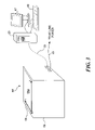
- FIGS. 7A-7C illustrate that manipulation of images may be accomplished using physical objects other than or in addition to a user's fingers.
- interactive display surface 400 displays an image 702 .
- a first hand 710 holds a first inanimate physical object 712 (such as a pencil eraser) that is touched to a first point 714 the interactive display surface to manipulate image 702 .
- a second hand 720 a the user holds a second inanimate object 722 a .
- second inanimate object 722 a is a paint brush, and the user directs the non-bristle end of second inanimate object 722 a to a second point 718 on interactive display surface 400 to manipulate image 702 .
- inanimate objects 712 and 722 a may be used.
- the user can manipulate image 702 with first inanimate object 712 , which is held in user's first hand, and using a finger 722 b of the user's second hand.
- any number or combination of physical objects may be used to manipulate an image, so as to resize, rotate, move, or crop the image or any other type of virtual entity that is presented on the interactive display surface.
- the present invention enables a user to use physical objects to adjust other attributes employed in an application executing in connection with the interactive display surface.
- a user has used a first hand 802 to direct a paint brush 804 to create an image 810 on interactive display surface 400 .
- a paint brush 804 may be used to create image 810 on interactive display surface.
- One manner by which such a physical object as the paint brush 804 may be used to create image 810 on interactive display surface is described in a co-pending patent application entitled, “Using Size And Shape Of A Physical Object To Manipulate Output In An Interactive Display Application,” Ser. No. 10/879,872, which was filed on Jun. 28, 2004.
- the user In order to begin manipulation of attributes of an image, with a first hand 802 b , the user identifies a portion 812 a of image 810 .
- the user selects a portion 812 a of image 810 by touching the portion with a finger 806 b .
- Identification of a portion of an image—or an aspect of any other application executing on interactive display surface 400 —for which an attribute is to be changed using the present invention can be performed in any manner understood by interactive display surface 400 and/or the application executing.
- an application may prompt a user for attribute changes during phases of application execution.
- a highlighted outline 814 indicates an attribute is to be changed for a selected portion 812 a of an image 810 a.
- a user places a second finger 822 from a second hand 820 on interactive display surface 400 . Because selected portion 812 a of image 810 a was selected, in response to a prompt, or because it was triggered by another event, when the user places second finger 822 on the interactive display surface, property selection range 830 is presented on interactive display surface 400 .
- Property selection range 830 may be a menu, a palette, a virtual slider control, or some other virtual control panel that includes an array of options.
- property selection range 830 includes a color or pattern palette presenting a number of attribute choices 832 from which the user may choose selected portion 812 a.
- Property selection range 830 is generated at a position where user's second finger 822 was disposed adjacent to interactive display surface 400 . Accordingly, the user can control where property selection range 830 will be presented by choosing where second finger 822 touches the interactive display surface.
- the property selection range is presented at a default size, but the present invention also enables a user to control a size of property selection range 830 , as described below in connection with FIGS. 9A-9D and FIGS. 10A-10D .
- the user employs a first hand 802 c to make a selection from property selection range 830 .
- the user places first finger 806 c adjacent to interactive display surface 400 to make a selection.
- the user can slide first finger 806 c to a desired choice or place first finger 806 c directly on the user's selection.
- the user selects attribute choice 834 .
- the user's selection is given effect once the user removes hands 820 and 802 c , and thus, fingers 822 and 806 c , from interactive display surface 400 .
- a selected portion 812 b is re-shaded in accordance with the user's selection of attribute 834 , resulting in a final image 810 b.
- property selection range 830 may be presented in a number of forms to facilitate a wide range of control types.
- property selection range 830 may include a palette, enabling a user to select among colors or patterns for filling or shading an image that the user has created. Any change made by the user can be propagated to the target object immediately to preview the effect of the change.
- the property selection range may also include line thicknesses and line patterns. In other applications, the property selection range can take a number of different forms.
- the property selection range may present virtual slider controls to change a brightness, contrast, intensity, or color temperature of an image.
- property selection range 430 may present virtual slider controls with which a user can control volume, bass, treble, loudness, or other attributes of the sound.
- a virtual slider could be presented as a jog control to provide a user with continuous forward and reverse playback control. Accordingly, it will be clear that any number of different types of attribute controls may be represented in the form of a property selection range.
- the property selection range can be invoked with almost any type of physical object.
- a user instead of a user employing fingers to call up a property selection range and to select an option from it, a user can use a pencil or paint brush, as described above in connection with FIGS. 7B and 7C , or any number of other types of physical objects.
- property selection ranges are preferably presented on the interactive display surface near where a physical object is disposed on or adjacent to the interactive display surface.
- a property selection range is invoked by successively placing two physical objects on an interactive display surface, and the property selection range is presented in the area bounded or otherwise indicated by the two physical objects. Accordingly, a user can cause the property selection range to be presented at a location and in a size that the user chooses. In this way, the user can avoid having the property selection range overlap an object of interest presented on the interactive display surface.
- the user can control the breadth of a range of control, to control the sensitivity of interactive display surface to movement of a physical object used to select and vary an attribute within the property selection range.
- a user's hand 900 a rests above interactive display surface 400 with a thumb 902 a disposed adjacent to the interactive display surface.
- No property selection range is yet generated on interactive display surface 400 , because interactive display surface 400 awaits a second physical object being disposed adjacent to the interactive display surface to mark a size of the property selection range.
- the user positions an index finger 904 b adjacent to interactive display surface 400 .
- thumb 902 b and index finger 904 b are both disposed adjacent to interactive display surface 400 .
- a property selection range 910 b is presented on the interactive display surface in the area between thumb 902 b and index finger 904 b.
- the user is not restricted to calling up a property selection range by first disposing a thumb adjacent to the interactive display surface.
- a hand 900 c rests above interactive display surface 400 with an index finger 904 c disposed adjacent to the interactive display surface.
- No property selection range is yet presented on interactive display surface 400 because interactive display surface 400 awaits a second physical object being disposed adjacent to the interactive display surface to mark an opposite end of the property selection range, to determine its size.
- the user disposes user's thumb 902 d adjacent to interactive display surface 400 .
- index finger 904 d and thumb 902 d are both disposed adjacent to interactive display surface 400 .
- property selection range 910 d is presented in the area between indicated by index finger 904 d and thumb 902 d.
- FIGS. 10A-10D further illustrate a user's control of the placement and sizing of a property selection range presented on the interactive display surface.
- FIG. 10A an image 1000 a with a portion 1010 a selected for input of an attribute change is presented on interactive display surface 400 .
- a first finger 1030 a of a first hand 1020 a is disposed adjacent to interactive display surface 400 .
- FIG. 10B a thumb 1040 b is also placed adjacent to interactive display surface 400 .
- a property selection range 1050 b is presented on the interactive display surface.
- property selection range 1050 b is sized to fit a region 1060 b determined by the distance between the first and second physical objects disposed adjacent to interactive display surface 400 .
- the first and second physical objects include first finger 1030 b and thumb 1040 b , and thus, region 1060 b , which is covered by property selection range 1050 b , spans an area determined by the distance between first finger 1030 b and thumb 1040 b.
- FIG. 10C shows a result of the user moving the fingers on interactive display surface 400 closer together.
- the user positioning of first finger 1030 c and thumb 1040 c adjacent to interactive display surface 400 results in a property selection range 1050 c being presented on interactive display surface 400 .
- a region 1060 c which is defined by the distance between first finger 1030 c and thumb 1040 c , is smaller in size. Consequently, property selection range 1050 c also is smaller.
- the present invention therefore, enables a user to control size and, as shown in FIG. 10D , placement of a property selection range 1050 d .
- Property selection range 1050 d is presented at a location and size determined by a first finger 1030 d and a thumb 1040 d of a user's hand 1020 d . Wherever property selection range 1050 d is presented on the interactive display surface, the user can engage property selection range 1050 d with a second hand 1060 d . Using a finger 1070 d on the user's second hand or another physical object, the user can select an attribute 1080 d from property selection range 1050 d , thereby changing selected portion 1010 d of image 1000 d.
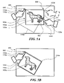
- property selection ranges are not limited to a single hierarchy or levels of attributes.
- the user disposes a first finger 1130 a and a thumb 1140 a of a first hand 1120 a adjacent to interactive display surface 400 .
- property selection range 1150 a is presented on interactive display surface 400 sized as determined by the distance between first finger 1130 a and thumb 1140 a .
- the user engages property selection range 1150 a .
- the user's selection of an attribute 1180 b results in the presentation of a second property selection range 1190 b .
- the user can navigate a hierarchy of menus 1150 b and 1190 b called up by user's placement of first finger 1130 b and thumb 1140 b of first hand 1120 b , and by a selection made with first finger 1170 b of second hand 11160 b.
- the user is not restricted to using fingers to interact with property selection ranges generated on the interactive display surface.
- the user can instead employ a wide range of physical objects to interact with interactive display surface 400 , and can use such objects to call up and work with property selection ranges having one or more hierarchical levels.
- FIGS. 12 , 13 A- 13 B, and 14 are flow diagrams illustrating the logical steps of engaging an interactive display surface with physical objects to provide input to an application executing on a computer system coupled to an interactive display surface. More particularly, FIGS. 12 , 13 A and 13 B include flow diagrams illustrating the logical steps for interacting with images generated on an interactive display surface as described above in connection with FIGS. 4A through 7C . FIG. 14 includes a flow diagram illustrating the logical steps for interacting with property selection ranges generated by an interactive display surface, as described above in connection with FIGS. 8A through 11B .
- FIG. 12 is a flow diagram 1201 illustrating the logical steps for manipulating an image presented on an interactive display surface using one or more physical objects.
- the flow diagram begins at a step 1201 , where the user initiates manipulation of an image (or other type of virtual entity) is presented on the interactive display surface.
- a decision step 1203 it is determined if a primary physical object has been disposed adjacent the interactive display surface in the area where the image is presented.
- a primary physical object signifies a first physical object to be disposed adjacent the interactive display surface after the image is presented. If it is determined at decision step 1203 that no primary physical object has been disposed adjacent the interactive display surface in the area where the image is presented, the flow diagram loops until an affirmative response occurs. Thus, no actions occur until a user engages the image presented on the interactive display surface with a primary physical object.
- a step 1205 associated a position of the primary physical object with a first point on the interactive display surface.
- a decision step 1207 it is determined if the primary physical object has been moved over the interactive display surface (but not moved away from it). In this case, the logic proceeds with a step 1209 , which updates a position of the image by moving the image relative to the interactive display surface so that the new position of the first point remains at the same relative position in the image.
- a decision step 1211 determines if the primary physical object is still adjacent to the interactive display surface, since if the user has taken the physical object away from, the user has completed the manipulation of the image by moving it to a new location with the physical object, and the logic then ends. If the primary physical object is still on the interactive display surface, the logic then loops back to step 1205 .
- a decision step 1213 provides for determining if an additional physical object has been placed adjacent to the interactive display surface. If not, the logic simply loops back to decision step 1207 . Conversely, if an additional object has been placed adjacent to the interactive display surface, a step 1215 associates the position of the additional physical object with a second point on the interactive display surface.
- the additional physical object may include another finger or another type of object disposed adjacent to the interactive display surface after the primary physical object is disposed on the interactive display surface. Again, as described above, both a primary physical object and an additional physical object are used for resizing and cropping an image on the interactive display surface.
- a decision step 1217 determines if the additional physical object has been positioned on the interactive display surface is either general horizontal or vertical alignment with the primary physical object. Clearly, some latitude is built into this test, so that if the primary and additional physical objects are not perfectly horizontally or vertically aligned, the test will still return a positive result. The allowed error in finding such alignment will likely be a few degrees. Horizontal and vertical are preferably determined in regard to the orthogonal X and Y axes of the interactive display surface, but can be predefined in regard to some other reference.
- step 1219 If the additional physical object is simply initially positioned in horizontal or vertical alignment with the primary physical object, or if it is then moved generally in the direction of the alignment, it is determined in a step 1219 that the user intends to enter the resize mode, which is illustrated in detail in FIG. 13A .
- a decision step 1221 determines if one the two physical objects is moving in an arc relative to the other, and if so, a step 1223 initiates the rotate mode, which as described above, rotates the image relative to the point that is not moving in the arc, by an extent determined by the angle subtended by the that the moving physical object. If a negative response is returned from decision step 1221 , a step 1225 places the interactive display table in the crop mode, which is discussed in greater detail in regard to FIG. 13B .
- FIG. 13A illustrates the logical steps for resizing an image presented on a surface, as indicated in an initial block 1202 . It is assumed that the logic of FIG. 12 has been employed to determine that the user intends to resize an image and that the first and second point for controlling this image manipulation have been determined based upon the positions of the primary physical object and the additional physical object.
- a decision step 1204 determines if the physical object remains adjacent to the interactive display surface. If so, a decision step 1206 determines if the user has selectively chosen an option (or the option is selected by default) so that the aspect ratio of the image will be retained during any resizing operations of the image.
- a step 1208 provides for scaling the image so that the image fits and is centered between the first point and the second point, while maintaining the aspect ratio of the original unmodified image.
- the image will be reduced in size, and the ratio of the dimension of the image between the point will be retained relative to the other dimension of the image.
- a step 1210 will scale only the dimension along the axis of the alignment between the primary and the additional physical object, so that the image is fitted and centered between the first point and the second point, but the other dimension will not be scaled (as shown in FIGS. 5C and 5D ).
- a decision step 1212 determines if the location of the primary physical object has moved. If so, a step 1214 moves the first point accordingly.
- a step 1216 applies the action of either step 1208 or 1210 , depending on the setting to maintain the aspect ratio, and resizes the image to fit between the new position of the first point and the position of the second point.
- a decision step 1218 determines if the location of the additional physical object has moved, and if so, the second point is correspondingly moved in a step 1220 .
- a step 1222 resizes the image (again either maintaining the aspect ratio or not, depending upon the result in decision step 1206 ), based upon the new position of the second point and the position of the first point.
- the logic returns to decision step 1204 . If the additional physical object has not been moved in decision step 1218 , the logic ends, it being assumed that the user has removed both of the physical objects from the interactive display surface, which will be the case for a negative response to decision step 1204 .
- FIG. 13B includes a flow diagram 1300 illustrating the logical steps for cropping an image presented on an interactive display surface. It should be noted that the logical steps illustrated in flow diagram 1300 may be executed in parallel with logical steps illustrated in flow diagram 1200 ( FIG. 13A ). As described above in connection with flow diagram 1200 , flow diagram 1300 assumes that the first and the second points have been determined and that they are not in either horizontal or vertical alignment, indicating that the user intends to crop the image presented on the interactive display surface, as noted in a block 1302 .
- Flow diagram 1300 proceeds to a decision step 1304 , which determines if both physical objects remain on the interactive display surface. If not, the logic ends, since the user may have decided not to crop (or may have completed cropping) the image. If so, the logic indicates the prospective cropped image using the first and second points to define diagonally opposite corners of the cropped image in a step 1306 .
- a decision step 1308 determines if the location of the primary physical object has moved over the interactive display surface. If so, a decision step 1310 determines if the additional object is still on the interactive display surface, and if not, a step 1312 shifts the cropped image relative to a new position of the first point corresponding to the movement of the primary physical object determined in decision step 1308 .
- this step moves the cropped image section to a different portion of the original image, while retaining its size, the user can move the cropped image area so that a desired portion of the original image is thus within the cropped image that is selected, so long as the primary physical object is not withdrawn from contact with the interactive display surface.
- the logic therefore returns to decision step 1304 .
- a step 1314 provides for revising the cropped image with the corner corresponding to the first point being moved to the new location of the first point. The logic again then returns to decision step 1304 .
- decision step 1308 determines if the location of the physical object has not moved since the position of the first point was last determined. If the determination in decision step 1308 is that the location of the physical object has not moved since the position of the first point was last determined, the logic proceeds to a decision step 1316 , which determines if the location of the additional physical object has been moved. If so, a step 1318 revised the cropped image with a corner positioned at the new location of the second point. The logic then again loops back to decision step 1304 . If the additional physical object was not moved, the logic also loops back to decision step 1304 , and the last cropped image that was determined will be used if both of the physical objects are moved away from the interactive display surface.
- the image is not actually cropped at step 1314 until the user indicates that the user has completed cropping the image by removing both physical objects from the interactive display surface.
- This approach enables the user to continue to see the original image the user is cropping, to assist the user in determining whether the user has cropped the image as desired.
- a computer system executing a program following flow diagram 1300 processes the steps very rapidly. Accordingly, even though cropping of the image according to the movements of the physical objects is handled in separate steps, cropping of the image based on the movements of both physical objects effectively occurs simultaneously.
- FIG. 14 is a flow diagram 1400 illustrating the logical steps for changing attributes of an application executing on a computer system coupled to an interactive display surface. As described above in connection with FIGS. 8A through 11B , placing a physical object on the interactive display surface presents controls on the interactive display surface that can be used to change a wide range of attributes.
- flow chart 1400 illustrates logical steps for presenting a property selection range that fits an area bounded by two physical objects, as described in connection with FIGS. 9A through 11B . Accordingly, unlike the embodiment of the invention illustrated in FIGS. 8A-8F , no property selection range is generated in response to a single physical object being disposed on the interactive display surface, although logical steps of flow chart 1400 could be modified to facilitate this alternative embodiment.
- Flow diagram 1400 begins at a step 1402 with enabling interactive display surface attribute selection.
- attribute selection may be invoked by a prompt, by user selection of an attribute on the interactive display surface, or in another appropriate manner.
- a decision step 1404 it is determined if a primary physical object has been disposed adjacent the interactive display surface. If not, the flow diagram loops awaiting an affirmative response to decision step 1404 .
- decision step 1404 determines if a primary physical object has been disposed adjacent to the interactive display surface. If not, flow diagram 1400 loops awaiting an affirmative response to decision step 1404 .
- a property selection range is presented on the interactive display surface.
- the property selection range can be a menu, a palette, a slider control, another virtual control, or any other array of attribute options, depending on the application and context enabling the attribute selection.
- the property selection range is sized to fit the area determined by the locations of the primary and secondary physical objects.
- a decision step 1412 it is determined if the primary and secondary physical objects remain disposed adjacent the interactive display surface. If either or both of the physical objects are removed from adjacent the interactive display surface, it is assumed that the user has discontinued or finished the attribute selection, and flow diagram 1400 returns to decision step 1404 to await a primary physical object once more being disposed adjacent the interactive display surface. On the other hand, if it is determined at decision step 1412 that the primary and secondary physical objects remain disposed adjacent the interactive display surface, flow diagram 1400 proceeds to a decision step 1414 , where it is determined if an additional physical object is disposed adjacent the interactive display surface in the area where the property selection range is generated. As described above in connection with FIGS.
- the primary and secondary physical objects such as a finger and thumb of a user's first hand, define the property selection range, while an additional physical object, such as a finger of the user's other hand, is used to make a selection from the property selection range. If it is determined at decision step 1414 that no additional physical object has been disposed adjacent the interactive display surface within the property selection range, flow diagram 1400 loops to decision step 1412 .
- a property included in the property selection range nearest a location where the additional physical object is disposed is identified.
- an additional range of properties such as a sub-menu described in connection with FIGS. 11A and 11B , is associated with the property identified at step 1416 . If so, the additional property selection range is presented on the interactive display surface.
- a selected property may be chosen by indicating it with the additional physical object and then removing the additional physical object from adjacent the interactive display surface. A selected property may also be chosen by tapping the selected property, or in a number of other ways.
- the selected property is effectuated by changing the attribute associated with the selected property or otherwise responding to the selected property.
- Flow diagram 1400 ends at a step 1426 .
Abstract
Description
-
- exit through the table surface without illuminating any objects, as indicated by
dash line 78 a; - illuminate objects on the table surface, as indicated by
dash line 78 b; or - illuminate objects a short distance above the table surface but not touching the table surface, as indicated by
dash line 78 c.
- exit through the table surface without illuminating any objects, as indicated by
-
- reflected back through
translucent layer 64 b, throughIR pass filter 86 a and into the lens ofdigital video camera 68, as indicated bydash lines - reflected or absorbed by other interior surfaces within the interactive display without entering the lens of
digital video camera 68, as indicated bydash line 80 c.
- reflected back through
Claims (47)
Priority Applications (1)
| Application Number | Priority Date | Filing Date | Title |
|---|---|---|---|
| US10/883,515 US7743348B2 (en) | 2004-06-30 | 2004-06-30 | Using physical objects to adjust attributes of an interactive display application |
Applications Claiming Priority (1)
| Application Number | Priority Date | Filing Date | Title |
|---|---|---|---|
| US10/883,515 US7743348B2 (en) | 2004-06-30 | 2004-06-30 | Using physical objects to adjust attributes of an interactive display application |
Publications (2)
| Publication Number | Publication Date |
|---|---|
| US20060001650A1 US20060001650A1 (en) | 2006-01-05 |
| US7743348B2 true US7743348B2 (en) | 2010-06-22 |
Family
ID=35513358
Family Applications (1)
| Application Number | Title | Priority Date | Filing Date |
|---|---|---|---|
| US10/883,515 Expired - Fee Related US7743348B2 (en) | 2004-06-30 | 2004-06-30 | Using physical objects to adjust attributes of an interactive display application |
Country Status (1)
| Country | Link |
|---|---|
| US (1) | US7743348B2 (en) |
Cited By (159)
| Publication number | Priority date | Publication date | Assignee | Title |
|---|---|---|---|---|
| US20080165142A1 (en) * | 2006-10-26 | 2008-07-10 | Kenneth Kocienda | Portable Multifunction Device, Method, and Graphical User Interface for Adjusting an Insertion Point Marker |
| US20080231611A1 (en) * | 2004-04-29 | 2008-09-25 | Microsoft Corporation | Interaction between objects and a virtual environment display |
| US20080263445A1 (en) * | 2007-04-20 | 2008-10-23 | Jun Serk Park | Editing of data using mobile communication terminal |
| US20080281851A1 (en) * | 2007-05-09 | 2008-11-13 | Microsoft Corporation | Archive for Physical and Digital Objects |
| US20090109231A1 (en) * | 2007-10-26 | 2009-04-30 | Sung Nam Kim | Imaging Device Providing Soft Buttons and Method of Changing Attributes of the Soft Buttons |
| US20090125848A1 (en) * | 2007-11-14 | 2009-05-14 | Susann Marie Keohane | Touch surface-sensitive edit system |
| US20090228792A1 (en) * | 2008-03-04 | 2009-09-10 | Van Os Marcel | Methods and Graphical User Interfaces for Editing on a Portable Multifunction Device |
| US20090228842A1 (en) * | 2008-03-04 | 2009-09-10 | Apple Inc. | Selecting of text using gestures |
| US20090254855A1 (en) * | 2008-04-08 | 2009-10-08 | Sony Ericsson Mobile Communications, Ab | Communication terminals with superimposed user interface |
| US20090327871A1 (en) * | 2008-06-26 | 2009-12-31 | Microsoft Corporation | I/o for constrained devices |
| US20100026649A1 (en) * | 2008-07-31 | 2010-02-04 | Canon Kabushiki Kaisha | Information processing apparatus and control method thereof |
| US20100039446A1 (en) * | 2004-08-06 | 2010-02-18 | Applied Minds, Inc. | Touch driven method and apparatus to integrate and display multiple image layers forming alternate depictions of same subject matter |
| US20100088653A1 (en) * | 2008-10-07 | 2010-04-08 | Research In Motion Limited | Portable electronic device and method of controlling same |
| US20100117979A1 (en) * | 2004-08-06 | 2010-05-13 | Touchtable, Inc. | Bounding box gesture recognition on a touch detecting interactive display |
| US20100125787A1 (en) * | 2008-11-20 | 2010-05-20 | Canon Kabushiki Kaisha | Information processing apparatus, processing method thereof, and computer-readable storage medium |
| US20100194781A1 (en) * | 2008-12-15 | 2010-08-05 | Christopher Tossing | System and method for cropping and annotating images on a touch sensitive display device |
| US20100235778A1 (en) * | 2009-03-16 | 2010-09-16 | Kocienda Kenneth L | Methods and Graphical User Interfaces for Editing on a Multifunction Device with a Touch Screen Display |
| US20100259500A1 (en) * | 2004-07-30 | 2010-10-14 | Peter Kennedy | Visual Expander |
| US20100299638A1 (en) * | 2009-05-25 | 2010-11-25 | Choi Jin-Won | Function execution method and apparatus thereof |
| US20110041098A1 (en) * | 2009-08-14 | 2011-02-17 | James Thomas Kajiya | Manipulation of 3-dimensional graphical objects or view in a multi-touch display |
| US20110072375A1 (en) * | 2009-09-22 | 2011-03-24 | Victor B Michael | Device, Method, and Graphical User Interface for Manipulating User Interface Objects |
| US20110115947A1 (en) * | 2009-11-19 | 2011-05-19 | Samsung Electronics Co., Ltd. | Digital photographing apparatus, method of controlling digital photographing apparatus, and recording medium for storing program to execute method of controlling digital photographing apparatus |
| US20110122458A1 (en) * | 2009-11-24 | 2011-05-26 | Internation Business Machines Corporation | Scanning and Capturing Digital Images Using Residue Detection |
| US20110141043A1 (en) * | 2009-12-11 | 2011-06-16 | Dassault Systemes | Method and sytem for duplicating an object using a touch-sensitive display |
| US20110185289A1 (en) * | 2010-01-28 | 2011-07-28 | Yang Pan | Portable tablet computing device with two display screens |
| US20110181527A1 (en) * | 2010-01-26 | 2011-07-28 | Jay Christopher Capela | Device, Method, and Graphical User Interface for Resizing Objects |
| US20110205246A1 (en) * | 2007-03-14 | 2011-08-25 | Microsoft Corporation | Virtual features of physical items |
| US20110234878A1 (en) * | 2010-03-26 | 2011-09-29 | Sony Corporation | Imaging apparatus and program |
| US20120030568A1 (en) * | 2010-07-30 | 2012-02-02 | Migos Charles J | Device, Method, and Graphical User Interface for Copying User Interface Objects Between Content Regions |
| US20120182224A1 (en) * | 2011-01-13 | 2012-07-19 | Sony Computer Entertainment America Llc | Handing control of an object from one touch input to another touch input |
| US20120210200A1 (en) * | 2011-02-10 | 2012-08-16 | Kelly Berger | System, method, and touch screen graphical user interface for managing photos and creating photo books |
| US20120307047A1 (en) * | 2011-06-01 | 2012-12-06 | Canon Kabushiki Kaisha | Imaging system and control method thereof |
| US8334867B1 (en) * | 2008-11-25 | 2012-12-18 | Perceptive Pixel Inc. | Volumetric data exploration using multi-point input controls |
| US20120327121A1 (en) * | 2011-06-22 | 2012-12-27 | Honeywell International Inc. | Methods for touch screen control of paperless recorders |
| US20130010068A1 (en) * | 2011-04-12 | 2013-01-10 | Radiation Monitoring Devices, Inc. | Augmented reality system |
| CN102902385A (en) * | 2011-07-25 | 2013-01-30 | 联咏科技股份有限公司 | Zoom gesture judgment method and touch inductive control chip |
| US8407606B1 (en) | 2009-01-02 | 2013-03-26 | Perceptive Pixel Inc. | Allocating control among inputs concurrently engaging an object displayed on a multi-touch device |
| US8456438B2 (en) | 2008-01-04 | 2013-06-04 | Tactus Technology, Inc. | User interface system |
| US8539386B2 (en) | 2010-01-26 | 2013-09-17 | Apple Inc. | Device, method, and graphical user interface for selecting and moving objects |
| US8539385B2 (en) | 2010-01-26 | 2013-09-17 | Apple Inc. | Device, method, and graphical user interface for precise positioning of objects |
| US20130252730A1 (en) * | 2008-11-14 | 2013-09-26 | Wms Gaming, Inc. | Storing and using casino content |
| US8547339B2 (en) | 2008-01-04 | 2013-10-01 | Tactus Technology, Inc. | System and methods for raised touch screens |
| US8553005B2 (en) | 2008-01-04 | 2013-10-08 | Tactus Technology, Inc. | User interface system |
| US8570295B2 (en) | 2008-01-04 | 2013-10-29 | Tactus Technology, Inc. | User interface system |
| US8587541B2 (en) | 2010-04-19 | 2013-11-19 | Tactus Technology, Inc. | Method for actuating a tactile interface layer |
| US8587548B2 (en) | 2009-07-03 | 2013-11-19 | Tactus Technology, Inc. | Method for adjusting the user interface of a device |
| US8610924B2 (en) | 2009-11-24 | 2013-12-17 | International Business Machines Corporation | Scanning and capturing digital images using layer detection |
| US8619035B2 (en) | 2010-02-10 | 2013-12-31 | Tactus Technology, Inc. | Method for assisting user input to a device |
| US8650634B2 (en) | 2009-01-14 | 2014-02-11 | International Business Machines Corporation | Enabling access to a subset of data |
| US8661339B2 (en) | 2011-05-31 | 2014-02-25 | Apple Inc. | Devices, methods, and graphical user interfaces for document manipulation |
| US8665239B2 (en) | 2004-08-06 | 2014-03-04 | Qualcomm Incorporated | Method and apparatus continuing action of user gestures performed upon a touch sensitive interactive display in simulation of inertia |
| US20140074426A1 (en) * | 2004-07-30 | 2014-03-13 | Apple Inc | Proximity detector in handheld device |
| US20140104320A1 (en) * | 2012-10-17 | 2014-04-17 | Perceptive Pixel, Inc. | Controlling Virtual Objects |
| US8704790B2 (en) | 2010-10-20 | 2014-04-22 | Tactus Technology, Inc. | User interface system |
| US20140125704A1 (en) * | 2011-07-29 | 2014-05-08 | Otto K. Sievert | System and method of visual layering |
| US20140152605A1 (en) * | 2006-10-13 | 2014-06-05 | Sony Corporation | Information display apparatus with proximity detection performance and information display method using the same |
| US8766928B2 (en) | 2009-09-25 | 2014-07-01 | Apple Inc. | Device, method, and graphical user interface for manipulating user interface objects |
| US20140184546A1 (en) * | 2012-12-31 | 2014-07-03 | Joao Aranda Brandao | Tool and Method for Emulating Flat-Tip Brush |
| US8780069B2 (en) | 2009-09-25 | 2014-07-15 | Apple Inc. | Device, method, and graphical user interface for manipulating user interface objects |
| US8799826B2 (en) | 2009-09-25 | 2014-08-05 | Apple Inc. | Device, method, and graphical user interface for moving a calendar entry in a calendar application |
| US8832585B2 (en) | 2009-09-25 | 2014-09-09 | Apple Inc. | Device, method, and graphical user interface for manipulating workspace views |
| US8845107B1 (en) | 2010-12-23 | 2014-09-30 | Rawles Llc | Characterization of a scene with structured light |
| US8845110B1 (en) | 2010-12-23 | 2014-09-30 | Rawles Llc | Powered augmented reality projection accessory display device |
| US8905551B1 (en) * | 2010-12-23 | 2014-12-09 | Rawles Llc | Unpowered augmented reality projection accessory display device |
| US8922503B2 (en) | 2008-01-04 | 2014-12-30 | Tactus Technology, Inc. | User interface system |
| US8922510B2 (en) | 2008-01-04 | 2014-12-30 | Tactus Technology, Inc. | User interface system |
| US8922502B2 (en) | 2008-01-04 | 2014-12-30 | Tactus Technology, Inc. | User interface system |
| US8928621B2 (en) | 2008-01-04 | 2015-01-06 | Tactus Technology, Inc. | User interface system and method |
| US8947383B2 (en) | 2008-01-04 | 2015-02-03 | Tactus Technology, Inc. | User interface system and method |
| US8972879B2 (en) | 2010-07-30 | 2015-03-03 | Apple Inc. | Device, method, and graphical user interface for reordering the front-to-back positions of objects |
| US9013417B2 (en) | 2008-01-04 | 2015-04-21 | Tactus Technology, Inc. | User interface system |
| US9052790B2 (en) | 2008-01-04 | 2015-06-09 | Tactus Technology, Inc. | User interface and methods |
| US9063627B2 (en) | 2008-01-04 | 2015-06-23 | Tactus Technology, Inc. | User interface and methods |
| US9075525B2 (en) | 2008-01-04 | 2015-07-07 | Tactus Technology, Inc. | User interface system |
| US9081494B2 (en) | 2010-07-30 | 2015-07-14 | Apple Inc. | Device, method, and graphical user interface for copying formatting attributes |
| US9111326B1 (en) | 2010-12-21 | 2015-08-18 | Rawles Llc | Designation of zones of interest within an augmented reality environment |
| US9118782B1 (en) | 2011-09-19 | 2015-08-25 | Amazon Technologies, Inc. | Optical interference mitigation |
| US9116617B2 (en) | 2009-07-03 | 2015-08-25 | Tactus Technology, Inc. | User interface enhancement system |
| US9132346B2 (en) | 2012-04-04 | 2015-09-15 | Kenneth J. Huebner | Connecting video objects and physical objects for handheld projectors |
| US9134593B1 (en) | 2010-12-23 | 2015-09-15 | Amazon Technologies, Inc. | Generation and modulation of non-visible structured light for augmented reality projection system |
| US20150268735A1 (en) * | 2012-10-05 | 2015-09-24 | Nec Solution Innovators, Ltd. | User interface device and user interface method |
| US20150339860A1 (en) * | 2014-05-26 | 2015-11-26 | Kyocera Document Solutions Inc. | Article information providing apparatus that provides information of article, article information providing system,and article information provision method |
| US20150363082A1 (en) * | 2014-06-17 | 2015-12-17 | Vmware, Inc. | User interface control based on pinch gestures |
| US9239623B2 (en) | 2010-01-05 | 2016-01-19 | Tactus Technology, Inc. | Dynamic tactile interface |
| US9274612B2 (en) | 2008-01-04 | 2016-03-01 | Tactus Technology, Inc. | User interface system |
| US9280224B2 (en) | 2012-09-24 | 2016-03-08 | Tactus Technology, Inc. | Dynamic tactile interface and methods |
| US9298261B2 (en) | 2008-01-04 | 2016-03-29 | Tactus Technology, Inc. | Method for actuating a tactile interface layer |
| US9348511B2 (en) | 2006-10-26 | 2016-05-24 | Apple Inc. | Method, system, and graphical user interface for positioning an insertion marker in a touch screen display |
| US9367132B2 (en) | 2008-01-04 | 2016-06-14 | Tactus Technology, Inc. | User interface system |
| US9372565B2 (en) | 2008-01-04 | 2016-06-21 | Tactus Technology, Inc. | Dynamic tactile interface |
| US9405417B2 (en) | 2012-09-24 | 2016-08-02 | Tactus Technology, Inc. | Dynamic tactile interface and methods |
| US9423875B2 (en) | 2008-01-04 | 2016-08-23 | Tactus Technology, Inc. | Dynamic tactile interface with exhibiting optical dispersion characteristics |
| US9508194B1 (en) | 2010-12-30 | 2016-11-29 | Amazon Technologies, Inc. | Utilizing content output devices in an augmented reality environment |
| US9552065B2 (en) | 2008-01-04 | 2017-01-24 | Tactus Technology, Inc. | Dynamic tactile interface |
| US9557813B2 (en) | 2013-06-28 | 2017-01-31 | Tactus Technology, Inc. | Method for reducing perceived optical distortion |
| US9557915B2 (en) | 2008-01-04 | 2017-01-31 | Tactus Technology, Inc. | Dynamic tactile interface |
| US9588683B2 (en) | 2008-01-04 | 2017-03-07 | Tactus Technology, Inc. | Dynamic tactile interface |
| US9588684B2 (en) | 2009-01-05 | 2017-03-07 | Tactus Technology, Inc. | Tactile interface for a computing device |
| US9602729B2 (en) | 2015-06-07 | 2017-03-21 | Apple Inc. | Devices and methods for capturing and interacting with enhanced digital images |
| US9607315B1 (en) | 2010-12-30 | 2017-03-28 | Amazon Technologies, Inc. | Complementing operation of display devices in an augmented reality environment |
| US9612659B2 (en) | 2008-01-04 | 2017-04-04 | Tactus Technology, Inc. | User interface system |
| US9612741B2 (en) | 2012-05-09 | 2017-04-04 | Apple Inc. | Device, method, and graphical user interface for displaying additional information in response to a user contact |
| US9619076B2 (en) | 2012-05-09 | 2017-04-11 | Apple Inc. | Device, method, and graphical user interface for transitioning between display states in response to a gesture |
| US9632664B2 (en) | 2015-03-08 | 2017-04-25 | Apple Inc. | Devices, methods, and graphical user interfaces for manipulating user interface objects with visual and/or haptic feedback |
| US9639184B2 (en) | 2015-03-19 | 2017-05-02 | Apple Inc. | Touch input cursor manipulation |
| US20170123635A1 (en) * | 2013-06-28 | 2017-05-04 | Beijing Qihoo Technology Company Limited | Method and device for webpage zooming on electronic apparatus |
| US9645732B2 (en) | 2015-03-08 | 2017-05-09 | Apple Inc. | Devices, methods, and graphical user interfaces for displaying and using menus |
| US9674426B2 (en) | 2015-06-07 | 2017-06-06 | Apple Inc. | Devices and methods for capturing and interacting with enhanced digital images |
| US9720501B2 (en) | 2008-01-04 | 2017-08-01 | Tactus Technology, Inc. | Dynamic tactile interface |
| US9721386B1 (en) | 2010-12-27 | 2017-08-01 | Amazon Technologies, Inc. | Integrated augmented reality environment |
| US9753639B2 (en) | 2012-05-09 | 2017-09-05 | Apple Inc. | Device, method, and graphical user interface for displaying content associated with a corresponding affordance |
| US9760172B2 (en) | 2008-01-04 | 2017-09-12 | Tactus Technology, Inc. | Dynamic tactile interface |
| US9778771B2 (en) | 2012-12-29 | 2017-10-03 | Apple Inc. | Device, method, and graphical user interface for transitioning between touch input to display output relationships |
| US9785305B2 (en) | 2015-03-19 | 2017-10-10 | Apple Inc. | Touch input cursor manipulation |
| US9830048B2 (en) | 2015-06-07 | 2017-11-28 | Apple Inc. | Devices and methods for processing touch inputs with instructions in a web page |
| US9875023B2 (en) | 2011-11-23 | 2018-01-23 | Microsoft Technology Licensing, Llc | Dial-based user interfaces |
| US9880735B2 (en) | 2015-08-10 | 2018-01-30 | Apple Inc. | Devices, methods, and graphical user interfaces for manipulating user interface objects with visual and/or haptic feedback |
| US9886184B2 (en) | 2012-05-09 | 2018-02-06 | Apple Inc. | Device, method, and graphical user interface for providing feedback for changing activation states of a user interface object |
| US9891811B2 (en) | 2015-06-07 | 2018-02-13 | Apple Inc. | Devices and methods for navigating between user interfaces |
| US9959025B2 (en) | 2012-12-29 | 2018-05-01 | Apple Inc. | Device, method, and graphical user interface for navigating user interface hierarchies |
| US20180120684A1 (en) * | 2016-05-24 | 2018-05-03 | Compal Electronics, Inc. | Smart lighting device and operation mode transforming method |
| US9990121B2 (en) | 2012-05-09 | 2018-06-05 | Apple Inc. | Device, method, and graphical user interface for moving a user interface object based on an intensity of a press input |
| US9990107B2 (en) | 2015-03-08 | 2018-06-05 | Apple Inc. | Devices, methods, and graphical user interfaces for displaying and using menus |
| US9996231B2 (en) | 2012-05-09 | 2018-06-12 | Apple Inc. | Device, method, and graphical user interface for manipulating framed graphical objects |
| US10037138B2 (en) | 2012-12-29 | 2018-07-31 | Apple Inc. | Device, method, and graphical user interface for switching between user interfaces |
| US10042542B2 (en) | 2012-05-09 | 2018-08-07 | Apple Inc. | Device, method, and graphical user interface for moving and dropping a user interface object |
| US10044790B2 (en) | 2005-06-24 | 2018-08-07 | Microsoft Technology Licensing, Llc | Extending digital artifacts through an interactive surface to a mobile device and creating a communication channel between a mobile device and a second mobile device via the interactive surface |
| US10048757B2 (en) | 2015-03-08 | 2018-08-14 | Apple Inc. | Devices and methods for controlling media presentation |
| US10055046B2 (en) | 2003-09-02 | 2018-08-21 | Apple Inc. | Touch-sensitive electronic apparatus for media applications, and methods therefor |
| US10067653B2 (en) | 2015-04-01 | 2018-09-04 | Apple Inc. | Devices and methods for processing touch inputs based on their intensities |
| US10073615B2 (en) | 2012-05-09 | 2018-09-11 | Apple Inc. | Device, method, and graphical user interface for displaying user interface objects corresponding to an application |
| US10078442B2 (en) | 2012-12-29 | 2018-09-18 | Apple Inc. | Device, method, and graphical user interface for determining whether to scroll or select content based on an intensity theshold |
| US10095391B2 (en) | 2012-05-09 | 2018-10-09 | Apple Inc. | Device, method, and graphical user interface for selecting user interface objects |
| US10095396B2 (en) | 2015-03-08 | 2018-10-09 | Apple Inc. | Devices, methods, and graphical user interfaces for interacting with a control object while dragging another object |
| US10126930B2 (en) | 2012-05-09 | 2018-11-13 | Apple Inc. | Device, method, and graphical user interface for scrolling nested regions |
| US10156941B2 (en) | 2013-02-14 | 2018-12-18 | Quickstep Technologies Llc | Method and device for navigating in a display screen and apparatus comprising such navigation |
| US10162452B2 (en) | 2015-08-10 | 2018-12-25 | Apple Inc. | Devices and methods for processing touch inputs based on their intensities |
| US10175864B2 (en) | 2012-05-09 | 2019-01-08 | Apple Inc. | Device, method, and graphical user interface for selecting object within a group of objects in accordance with contact intensity |
| US10175757B2 (en) | 2012-05-09 | 2019-01-08 | Apple Inc. | Device, method, and graphical user interface for providing tactile feedback for touch-based operations performed and reversed in a user interface |
| US10200598B2 (en) | 2015-06-07 | 2019-02-05 | Apple Inc. | Devices and methods for capturing and interacting with enhanced digital images |
| US10235035B2 (en) | 2015-08-10 | 2019-03-19 | Apple Inc. | Devices, methods, and graphical user interfaces for content navigation and manipulation |
| US10248308B2 (en) | 2015-08-10 | 2019-04-02 | Apple Inc. | Devices, methods, and graphical user interfaces for manipulating user interfaces with physical gestures |
| US10275087B1 (en) | 2011-08-05 | 2019-04-30 | P4tents1, LLC | Devices, methods, and graphical user interfaces for manipulating user interface objects with visual and/or haptic feedback |
| US10303266B2 (en) | 2011-01-31 | 2019-05-28 | Quickstep Technologies Llc | Three-dimensional man/machine interface |
| US20190171347A1 (en) * | 2012-11-02 | 2019-06-06 | Atheer, Inc. | Method and apparatus for a three dimensional interface |
| US10346030B2 (en) | 2015-06-07 | 2019-07-09 | Apple Inc. | Devices and methods for navigating between user interfaces |
| US10416800B2 (en) | 2015-08-10 | 2019-09-17 | Apple Inc. | Devices, methods, and graphical user interfaces for adjusting user interface objects |
| US10417801B2 (en) | 2014-11-13 | 2019-09-17 | Hewlett-Packard Development Company, L.P. | Image projection |
| US10437333B2 (en) | 2012-12-29 | 2019-10-08 | Apple Inc. | Device, method, and graphical user interface for forgoing generation of tactile output for a multi-contact gesture |
| US10496260B2 (en) | 2012-05-09 | 2019-12-03 | Apple Inc. | Device, method, and graphical user interface for pressure-based alteration of controls in a user interface |
| US10586478B2 (en) | 2018-03-01 | 2020-03-10 | International Business Machines Corporation | Dynamically reforming surfaces to deliver physicality in introductory child education |
| US10620781B2 (en) | 2012-12-29 | 2020-04-14 | Apple Inc. | Device, method, and graphical user interface for moving a cursor according to a change in an appearance of a control icon with simulated three-dimensional characteristics |
| US11080937B2 (en) * | 2014-05-20 | 2021-08-03 | Ultrahaptics IP Two Limited | Wearable augmented reality devices with object detection and tracking |
| US11221748B2 (en) * | 2014-06-04 | 2022-01-11 | Quantum Interface, Llc | Apparatuses for selection objects in Virtual or Augmented Reality environments |
| US11379113B2 (en) | 2019-06-01 | 2022-07-05 | Apple Inc. | Techniques for selecting text |
| US20220236855A1 (en) * | 2021-01-27 | 2022-07-28 | Ford Global Technologies, Llc | Systems And Methods For Interacting With A Tabletop Model Using A Mobile Device |
| US20220283647A1 (en) * | 2021-03-05 | 2022-09-08 | MediVis, Inc. | User input and virtual touch pad in augmented reality for use in surgical settings |
| US11778159B2 (en) | 2014-08-08 | 2023-10-03 | Ultrahaptics IP Two Limited | Augmented reality with motion sensing |
| US11782513B2 (en) | 2015-01-16 | 2023-10-10 | Ultrahaptics IP Two Limited | Mode switching for integrated gestural interaction and multi-user collaboration in immersive virtual reality environments |
Families Citing this family (246)
| Publication number | Priority date | Publication date | Assignee | Title |
|---|---|---|---|---|
| GB9722766D0 (en) | 1997-10-28 | 1997-12-24 | British Telecomm | Portable computers |
| US9292111B2 (en) * | 1998-01-26 | 2016-03-22 | Apple Inc. | Gesturing with a multipoint sensing device |
| US9239673B2 (en) | 1998-01-26 | 2016-01-19 | Apple Inc. | Gesturing with a multipoint sensing device |
| US7614008B2 (en) * | 2004-07-30 | 2009-11-03 | Apple Inc. | Operation of a computer with touch screen interface |
| US20060033724A1 (en) * | 2004-07-30 | 2006-02-16 | Apple Computer, Inc. | Virtual input device placement on a touch screen user interface |
| US8479122B2 (en) * | 2004-07-30 | 2013-07-02 | Apple Inc. | Gestures for touch sensitive input devices |
| US7358962B2 (en) * | 2004-06-15 | 2008-04-15 | Microsoft Corporation | Manipulating association of data with a physical object |
| US7653883B2 (en) | 2004-07-30 | 2010-01-26 | Apple Inc. | Proximity detector in handheld device |
| JP4351599B2 (en) * | 2004-09-03 | 2009-10-28 | パナソニック株式会社 | Input device |
| US20060072009A1 (en) * | 2004-10-01 | 2006-04-06 | International Business Machines Corporation | Flexible interaction-based computer interfacing using visible artifacts |
| US7925996B2 (en) * | 2004-11-18 | 2011-04-12 | Microsoft Corporation | Method and system for providing multiple input connecting user interface |
| US7489305B2 (en) * | 2004-12-01 | 2009-02-10 | Thermoteknix Systems Limited | Touch screen control |
| US7679625B1 (en) * | 2005-01-07 | 2010-03-16 | Apple, Inc. | Straightening digital images |
| US7760189B2 (en) * | 2005-01-21 | 2010-07-20 | Lenovo Singapore Pte. Ltd | Touchpad diagonal scrolling |
| US7450086B2 (en) * | 2005-03-14 | 2008-11-11 | Hewlett-Packard Development Company, L.P. | Projector |
| KR20070043332A (en) * | 2005-10-21 | 2007-04-25 | 삼성전자주식회사 | Display apparatus and control method thereof |
| US8018440B2 (en) | 2005-12-30 | 2011-09-13 | Microsoft Corporation | Unintentional touch rejection |
| US8077153B2 (en) * | 2006-04-19 | 2011-12-13 | Microsoft Corporation | Precise selection techniques for multi-touch screens |
| US8443298B2 (en) * | 2006-06-30 | 2013-05-14 | International Business Machines Corporation | Method and apparatus for repositioning a horizontally or vertically maximized display window |
| JP2008052062A (en) * | 2006-08-24 | 2008-03-06 | Ricoh Co Ltd | Display device, display method of display device, program and recording medium |
| US9304675B2 (en) | 2006-09-06 | 2016-04-05 | Apple Inc. | Portable electronic device for instant messaging |
| US7956849B2 (en) | 2006-09-06 | 2011-06-07 | Apple Inc. | Video manager for portable multifunction device |
| US8564544B2 (en) | 2006-09-06 | 2013-10-22 | Apple Inc. | Touch screen device, method, and graphical user interface for customizing display of content category icons |
| JP4789759B2 (en) * | 2006-09-15 | 2011-10-12 | キヤノン株式会社 | Display control apparatus and control method thereof |
| GB2443010B (en) * | 2006-10-10 | 2009-09-02 | Promethean Technologies Group | Interactive display system |
| TWI399670B (en) * | 2006-12-21 | 2013-06-21 | Elan Microelectronics Corp | Operation control methods and systems, and machine readable medium thereof |
| US7956847B2 (en) * | 2007-01-05 | 2011-06-07 | Apple Inc. | Gestures for controlling, manipulating, and editing of media files using touch sensitive devices |
| US8689132B2 (en) | 2007-01-07 | 2014-04-01 | Apple Inc. | Portable electronic device, method, and graphical user interface for displaying electronic documents and lists |
| US7844915B2 (en) | 2007-01-07 | 2010-11-30 | Apple Inc. | Application programming interfaces for scrolling operations |
| US8615714B2 (en) | 2007-01-22 | 2013-12-24 | Textron Innovations Inc. | System and method for performing multiple, simultaneous, independent simulations in a motion capture environment |
| WO2008091857A1 (en) * | 2007-01-22 | 2008-07-31 | Bell Helicopter Textron, Inc. | System and method for controlling a virtual reality environment by an actor in the virtual reality environment |
| EP2111606A4 (en) * | 2007-01-22 | 2013-07-31 | Bell Helicopter Textron Inc | System and method for the interactive display of data in a motion capture environment |
| KR101361691B1 (en) * | 2007-02-21 | 2014-02-13 | 삼성전자주식회사 | Method for obtaining partial image of portable terminal having touch screen |
| US7533059B2 (en) * | 2007-03-14 | 2009-05-12 | Microsoft Corporation | Purchasing using a physical object |
| US20080231926A1 (en) * | 2007-03-19 | 2008-09-25 | Klug Michael A | Systems and Methods for Updating Dynamic Three-Dimensional Displays with User Input |
| US20110035684A1 (en) * | 2007-04-17 | 2011-02-10 | Bell Helicoper Textron Inc. | Collaborative Virtual Reality System Using Multiple Motion Capture Systems and Multiple Interactive Clients |
| JP4924281B2 (en) * | 2007-08-15 | 2012-04-25 | ブラザー工業株式会社 | Image processing apparatus and program |
| JP4904223B2 (en) * | 2007-08-23 | 2012-03-28 | キヤノン株式会社 | Image processing apparatus and image processing method |
| JP4569613B2 (en) * | 2007-09-19 | 2010-10-27 | ソニー株式会社 | Image processing apparatus, image processing method, and program |
| KR101415763B1 (en) * | 2007-10-04 | 2014-07-08 | 엘지전자 주식회사 | Mobile terminal and its image display method |
| US9134904B2 (en) | 2007-10-06 | 2015-09-15 | International Business Machines Corporation | Displaying documents to a plurality of users of a surface computer |
| US8139036B2 (en) * | 2007-10-07 | 2012-03-20 | International Business Machines Corporation | Non-intrusive capture and display of objects based on contact locality |
| US20090091539A1 (en) * | 2007-10-08 | 2009-04-09 | International Business Machines Corporation | Sending A Document For Display To A User Of A Surface Computer |
| US20090091529A1 (en) * | 2007-10-09 | 2009-04-09 | International Business Machines Corporation | Rendering Display Content On A Floor Surface Of A Surface Computer |
| US8024185B2 (en) | 2007-10-10 | 2011-09-20 | International Business Machines Corporation | Vocal command directives to compose dynamic display text |
| KR100790960B1 (en) * | 2007-10-16 | 2008-01-03 | 주식회사 모비더스 | A mobile terminal and method for generating the embedded drawing data based on flash image |
| US8004498B1 (en) * | 2007-10-22 | 2011-08-23 | Adobe Systems Incorporated | Systems and methods for multipoint temporary anchoring |
| US9171454B2 (en) | 2007-11-14 | 2015-10-27 | Microsoft Technology Licensing, Llc | Magic wand |
| EP2234037B1 (en) * | 2007-12-04 | 2012-02-01 | A.T Communications Co., Ltd. | Two-dimensional code display system, two-dimensional code display method, and program |
| KR20090058073A (en) * | 2007-12-04 | 2009-06-09 | 삼성전자주식회사 | Terminal and method for performing function thereof |
| US9203833B2 (en) * | 2007-12-05 | 2015-12-01 | International Business Machines Corporation | User authorization using an automated Turing Test |
| EP2243072A2 (en) * | 2008-01-23 | 2010-10-27 | N-Trig Ltd. | Graphical object manipulation with a touch sensitive screen |
| US20090207142A1 (en) * | 2008-02-20 | 2009-08-20 | Nokia Corporation | Apparatus, method, computer program and user interface for enabling user input |
| US8315479B1 (en) * | 2008-02-26 | 2012-11-20 | Adobe Systems Incorporated | Slicing and scaling figures |
| US8233206B2 (en) * | 2008-03-18 | 2012-07-31 | Zebra Imaging, Inc. | User interaction with holographic images |
| US8723811B2 (en) * | 2008-03-21 | 2014-05-13 | Lg Electronics Inc. | Mobile terminal and screen displaying method thereof |
| US8788967B2 (en) * | 2008-04-10 | 2014-07-22 | Perceptive Pixel, Inc. | Methods of interfacing with multi-input devices and multi-input display systems employing interfacing techniques |
| US8745514B1 (en) | 2008-04-11 | 2014-06-03 | Perceptive Pixel, Inc. | Pressure-sensitive layering of displayed objects |
| US8952894B2 (en) | 2008-05-12 | 2015-02-10 | Microsoft Technology Licensing, Llc | Computer vision-based multi-touch sensing using infrared lasers |
| US8847739B2 (en) * | 2008-08-04 | 2014-09-30 | Microsoft Corporation | Fusing RFID and vision for surface object tracking |
| JP4640470B2 (en) * | 2008-08-18 | 2011-03-02 | ソニー株式会社 | Image processing apparatus, image processing method, program, and imaging apparatus |
| CA2734987A1 (en) * | 2008-08-22 | 2010-02-25 | Google Inc. | Navigation in a three dimensional environment on a mobile device |
| US8799811B2 (en) * | 2008-08-22 | 2014-08-05 | Siemens Aktiengesellschaft | Method and apparatus for displaying medical thumbnail objects in a browsing component |
| US20100060588A1 (en) * | 2008-09-09 | 2010-03-11 | Microsoft Corporation | Temporally separate touch input |
| MX2011003069A (en) * | 2008-09-24 | 2011-04-19 | Koninkl Philips Electronics Nv | A user interface for a multi-point touch sensitive device. |
| US8427424B2 (en) * | 2008-09-30 | 2013-04-23 | Microsoft Corporation | Using physical objects in conjunction with an interactive surface |
| EP2175354A1 (en) * | 2008-10-07 | 2010-04-14 | Research In Motion Limited | Portable electronic device and method of controlling same |
| US9442648B2 (en) * | 2008-10-07 | 2016-09-13 | Blackberry Limited | Portable electronic device and method of controlling same |
| SE533704C2 (en) | 2008-12-05 | 2010-12-07 | Flatfrog Lab Ab | Touch sensitive apparatus and method for operating the same |
| US20100149114A1 (en) * | 2008-12-16 | 2010-06-17 | Motorola, Inc. | Simulating a multi-touch screen on a single-touch screen |
| JP5108747B2 (en) * | 2008-12-26 | 2012-12-26 | 富士フイルム株式会社 | Information display apparatus, method and program |
| US8957865B2 (en) * | 2009-01-05 | 2015-02-17 | Apple Inc. | Device, method, and graphical user interface for manipulating a user interface object |
| JP2010176330A (en) * | 2009-01-28 | 2010-08-12 | Sony Corp | Information processing apparatus and display control method |
| KR101617645B1 (en) * | 2009-02-24 | 2016-05-04 | 삼성전자주식회사 | Method for controlling display and apparatus using the same |
| TW201032101A (en) * | 2009-02-26 | 2010-09-01 | Qisda Corp | Electronic device controlling method |
| US20100220066A1 (en) * | 2009-02-27 | 2010-09-02 | Murphy Kenneth M T | Handheld electronic device having a touchscreen and a method of using a touchscreen of a handheld electronic device |
| US9250788B2 (en) * | 2009-03-18 | 2016-02-02 | IdentifyMine, Inc. | Gesture handlers of a gesture engine |
| US20100251112A1 (en) * | 2009-03-24 | 2010-09-30 | Microsoft Corporation | Bimodal touch sensitive digital notebook |
| US8134539B2 (en) * | 2009-03-30 | 2012-03-13 | Eastman Kodak Company | Digital picture frame having near-touch and true-touch |
| US8884925B2 (en) | 2009-04-05 | 2014-11-11 | Radion Engineering Co. Ltd. | Display system and method utilizing optical sensors |
| KR101553629B1 (en) * | 2009-05-06 | 2015-09-17 | 삼성전자주식회사 | Method of Providing Interface |
| EP2254032A1 (en) | 2009-05-21 | 2010-11-24 | Research In Motion Limited | Portable electronic device and method of controlling same |
| US20100299641A1 (en) * | 2009-05-21 | 2010-11-25 | Research In Motion Limited | Portable electronic device and method of controlling same |
| US8473862B1 (en) * | 2009-05-21 | 2013-06-25 | Perceptive Pixel Inc. | Organizational tools on a multi-touch display device |
| US8836648B2 (en) * | 2009-05-27 | 2014-09-16 | Microsoft Corporation | Touch pull-in gesture |
| US20100302212A1 (en) * | 2009-06-02 | 2010-12-02 | Microsoft Corporation | Touch personalization for a display device |
| US8723988B2 (en) * | 2009-07-17 | 2014-05-13 | Sony Corporation | Using a touch sensitive display to control magnification and capture of digital images by an electronic device |
| US20110057886A1 (en) * | 2009-09-10 | 2011-03-10 | Oliver Ng | Dynamic sizing of identifier on a touch-sensitive display |
| KR101401808B1 (en) * | 2009-09-17 | 2014-05-29 | 닛본 덴끼 가부시끼가이샤 | Electronic apparatus using touch panel and setting value modification method of same |
| US9792012B2 (en) * | 2009-10-01 | 2017-10-17 | Mobile Imaging In Sweden Ab | Method relating to digital images |
| US8982070B2 (en) * | 2009-10-28 | 2015-03-17 | Nec Corporation | Portable information terminal |
| KR101635016B1 (en) * | 2009-11-19 | 2016-06-30 | 엘지전자 주식회사 | Mobile terminal and method for searching a map |
| KR20110055062A (en) * | 2009-11-19 | 2011-05-25 | 삼성전자주식회사 | Robot system and method for controlling the same |
| US20110151925A1 (en) * | 2009-12-18 | 2011-06-23 | Sony Ericsson Mobile Communications Ab | Image data generation in a portable electronic device |
| JP2011141753A (en) * | 2010-01-07 | 2011-07-21 | Sony Corp | Display control apparatus, display control method and display control program |
| US8239785B2 (en) * | 2010-01-27 | 2012-08-07 | Microsoft Corporation | Edge gestures |
| US20110185299A1 (en) * | 2010-01-28 | 2011-07-28 | Microsoft Corporation | Stamp Gestures |
| US9411504B2 (en) * | 2010-01-28 | 2016-08-09 | Microsoft Technology Licensing, Llc | Copy and staple gestures |
| US20110185320A1 (en) * | 2010-01-28 | 2011-07-28 | Microsoft Corporation | Cross-reference Gestures |
| US8261213B2 (en) | 2010-01-28 | 2012-09-04 | Microsoft Corporation | Brush, carbon-copy, and fill gestures |
| US20110191719A1 (en) * | 2010-02-04 | 2011-08-04 | Microsoft Corporation | Cut, Punch-Out, and Rip Gestures |
| US9519356B2 (en) * | 2010-02-04 | 2016-12-13 | Microsoft Technology Licensing, Llc | Link gestures |
| US20110191704A1 (en) * | 2010-02-04 | 2011-08-04 | Microsoft Corporation | Contextual multiplexing gestures |
| SE534551C2 (en) | 2010-02-15 | 2011-10-04 | Scalado Ab | Digital image manipulation including identification of a target area in a target image and seamless replacement of image information from a source image |
| US9965165B2 (en) * | 2010-02-19 | 2018-05-08 | Microsoft Technology Licensing, Llc | Multi-finger gestures |
| US8799827B2 (en) * | 2010-02-19 | 2014-08-05 | Microsoft Corporation | Page manipulations using on and off-screen gestures |
| US9310994B2 (en) | 2010-02-19 | 2016-04-12 | Microsoft Technology Licensing, Llc | Use of bezel as an input mechanism |
| US9274682B2 (en) * | 2010-02-19 | 2016-03-01 | Microsoft Technology Licensing, Llc | Off-screen gestures to create on-screen input |
| US9367205B2 (en) | 2010-02-19 | 2016-06-14 | Microsoft Technolgoy Licensing, Llc | Radial menus with bezel gestures |
| US8730309B2 (en) | 2010-02-23 | 2014-05-20 | Microsoft Corporation | Projectors and depth cameras for deviceless augmented reality and interaction |
| US20110209089A1 (en) * | 2010-02-25 | 2011-08-25 | Hinckley Kenneth P | Multi-screen object-hold and page-change gesture |
| US9075522B2 (en) * | 2010-02-25 | 2015-07-07 | Microsoft Technology Licensing, Llc | Multi-screen bookmark hold gesture |
| US8751970B2 (en) * | 2010-02-25 | 2014-06-10 | Microsoft Corporation | Multi-screen synchronous slide gesture |
| US20110209058A1 (en) * | 2010-02-25 | 2011-08-25 | Microsoft Corporation | Multi-screen hold and tap gesture |
| US8539384B2 (en) | 2010-02-25 | 2013-09-17 | Microsoft Corporation | Multi-screen pinch and expand gestures |
| US8707174B2 (en) * | 2010-02-25 | 2014-04-22 | Microsoft Corporation | Multi-screen hold and page-flip gesture |
| US9454304B2 (en) | 2010-02-25 | 2016-09-27 | Microsoft Technology Licensing, Llc | Multi-screen dual tap gesture |
| US8473870B2 (en) * | 2010-02-25 | 2013-06-25 | Microsoft Corporation | Multi-screen hold and drag gesture |
| US20110209101A1 (en) * | 2010-02-25 | 2011-08-25 | Hinckley Kenneth P | Multi-screen pinch-to-pocket gesture |
| CN102822770B (en) * | 2010-03-26 | 2016-08-17 | 惠普发展公司,有限责任合伙企业 | Associated with |
| IT1399695B1 (en) * | 2010-04-14 | 2013-04-26 | Sisvel Technology Srl | METHOD TO DISPLAY A VIDEO FLOW ACCORDING TO A CUSTOMIZED FORMAT. |
| WO2011130919A1 (en) | 2010-04-23 | 2011-10-27 | Motorola Mobility, Inc. | Electronic device and method using touch-detecting surface |
| WO2011152166A1 (en) * | 2010-05-31 | 2011-12-08 | 株式会社Pfu | Overhead scanner apparatus, image processing method, and program |
| EP2390772A1 (en) * | 2010-05-31 | 2011-11-30 | Sony Ericsson Mobile Communications AB | User interface with three dimensional user input |
| US8896621B1 (en) * | 2010-06-02 | 2014-11-25 | Pinger, Inc. | User-manipulable stencils for drawing application |
| US8749499B2 (en) * | 2010-06-08 | 2014-06-10 | Sap Ag | Touch screen for bridging multi and/or single touch points to applications |
| US20120011465A1 (en) * | 2010-07-06 | 2012-01-12 | Marcelo Amaral Rezende | Digital whiteboard system |
| US20120026100A1 (en) * | 2010-07-30 | 2012-02-02 | Migos Charles J | Device, Method, and Graphical User Interface for Aligning and Distributing Objects |
| KR101705872B1 (en) * | 2010-09-08 | 2017-02-10 | 삼성전자주식회사 | Method for selecting area on a screen in a mobile device and apparatus therefore |
| JP5263355B2 (en) * | 2010-09-22 | 2013-08-14 | 株式会社ニコン | Image display device and imaging device |
| JP5269851B2 (en) * | 2010-09-27 | 2013-08-21 | 富士フイルム株式会社 | Image editing apparatus, image editing method and program thereof |
| TW201220130A (en) * | 2010-11-15 | 2012-05-16 | Inst Information Industry | Electrical device and display method applying for electrical device and electrical device readable storage medium for storing thereof |
| CN102479007A (en) * | 2010-11-30 | 2012-05-30 | 英业达股份有限公司 | Optical keyboard |
| US20120159395A1 (en) | 2010-12-20 | 2012-06-21 | Microsoft Corporation | Application-launching interface for multiple modes |
| US8612874B2 (en) | 2010-12-23 | 2013-12-17 | Microsoft Corporation | Presenting an application change through a tile |
| US8689123B2 (en) | 2010-12-23 | 2014-04-01 | Microsoft Corporation | Application reporting in an application-selectable user interface |
| US9329469B2 (en) | 2011-02-17 | 2016-05-03 | Microsoft Technology Licensing, Llc | Providing an interactive experience using a 3D depth camera and a 3D projector |
| US9480907B2 (en) | 2011-03-02 | 2016-11-01 | Microsoft Technology Licensing, Llc | Immersive display with peripheral illusions |
| JP2012185647A (en) * | 2011-03-04 | 2012-09-27 | Sony Corp | Display controller, display control method and program |
| JP5792499B2 (en) * | 2011-04-07 | 2015-10-14 | シャープ株式会社 | Electronic device, display method, and display program |
| US8947429B2 (en) | 2011-04-12 | 2015-02-03 | Autodesk, Inc. | Gestures and tools for creating and editing solid models |
| US9182882B2 (en) | 2011-04-12 | 2015-11-10 | Autodesk, Inc. | Dynamic creation and modeling of solid models |
| US8902222B2 (en) | 2012-01-16 | 2014-12-02 | Autodesk, Inc. | Three dimensional contriver tool for modeling with multi-touch devices |
| US9158445B2 (en) | 2011-05-27 | 2015-10-13 | Microsoft Technology Licensing, Llc | Managing an immersive interface in a multi-application immersive environment |
| US9658766B2 (en) | 2011-05-27 | 2017-05-23 | Microsoft Technology Licensing, Llc | Edge gesture |
| US9104307B2 (en) | 2011-05-27 | 2015-08-11 | Microsoft Technology Licensing, Llc | Multi-application environment |
| US8893033B2 (en) | 2011-05-27 | 2014-11-18 | Microsoft Corporation | Application notifications |
| US9104440B2 (en) | 2011-05-27 | 2015-08-11 | Microsoft Technology Licensing, Llc | Multi-application environment |
| SE1150505A1 (en) | 2011-05-31 | 2012-12-01 | Mobile Imaging In Sweden Ab | Method and apparatus for taking pictures |
| US9597587B2 (en) | 2011-06-08 | 2017-03-21 | Microsoft Technology Licensing, Llc | Locational node device |
| JP5360140B2 (en) * | 2011-06-17 | 2013-12-04 | コニカミノルタ株式会社 | Information browsing apparatus, control program, and control method |
| US8860675B2 (en) * | 2011-07-12 | 2014-10-14 | Autodesk, Inc. | Drawing aid system for multi-touch devices |
| US9432583B2 (en) | 2011-07-15 | 2016-08-30 | Mobile Imaging In Sweden Ab | Method of providing an adjusted digital image representation of a view, and an apparatus |
| TWI457817B (en) * | 2011-07-26 | 2014-10-21 | Novatek Microelectronics Corp | Zoom gesture determination method and touch control chip |
| US9933935B2 (en) * | 2011-08-26 | 2018-04-03 | Apple Inc. | Device, method, and graphical user interface for editing videos |
| JP2013054470A (en) | 2011-09-01 | 2013-03-21 | Sony Corp | Information processor, information processing method, and program |
| US20130057587A1 (en) | 2011-09-01 | 2013-03-07 | Microsoft Corporation | Arranging tiles |
| US9146670B2 (en) | 2011-09-10 | 2015-09-29 | Microsoft Technology Licensing, Llc | Progressively indicating new content in an application-selectable user interface |
| US20130063369A1 (en) * | 2011-09-14 | 2013-03-14 | Verizon Patent And Licensing Inc. | Method and apparatus for media rendering services using gesture and/or voice control |
| US9851889B2 (en) * | 2011-09-16 | 2017-12-26 | Kt Corporation | Apparatus and method for rotating a displayed image by using multi-point touch inputs |
| TW201319921A (en) * | 2011-11-07 | 2013-05-16 | Benq Corp | Method for screen control and method for screen display on a touch screen |
| KR101905038B1 (en) | 2011-11-16 | 2018-10-08 | 삼성전자주식회사 | Apparatus having a touch screen under multiple applications environment and method for controlling thereof |
| KR20130082352A (en) * | 2012-01-11 | 2013-07-19 | 삼성전자주식회사 | Apparatus and method for zooming touch screen in electronic device |
| US9395901B2 (en) * | 2012-02-08 | 2016-07-19 | Blackberry Limited | Portable electronic device and method of controlling same |
| KR101932718B1 (en) * | 2012-02-24 | 2018-12-26 | 삼성전자주식회사 | Device and method for changing size of display window on screen |
| JP5978660B2 (en) * | 2012-03-06 | 2016-08-24 | ソニー株式会社 | Information processing apparatus and information processing method |
| KR20130110715A (en) * | 2012-03-30 | 2013-10-10 | 삼성전자주식회사 | Method and apparatus for providing flexible bezel |
| US20130265240A1 (en) * | 2012-04-06 | 2013-10-10 | At&T Intellectual Property I, Lp | Method and apparatus for presenting a virtual touchscreen |
| US8866771B2 (en) * | 2012-04-18 | 2014-10-21 | International Business Machines Corporation | Multi-touch multi-user gestures on a multi-touch display |
| US9293016B2 (en) | 2012-04-24 | 2016-03-22 | At&T Intellectual Property I, Lp | Method and apparatus for processing sensor data of detected objects |
| US10168835B2 (en) | 2012-05-23 | 2019-01-01 | Flatfrog Laboratories Ab | Spatial resolution in touch displays |
| US8671361B2 (en) * | 2012-05-24 | 2014-03-11 | Blackberry Limited | Presentation of image on display screen with combination crop and rotation and with auto-resizing of crop field |
| US9292243B2 (en) * | 2012-06-21 | 2016-03-22 | Sanford, L.P. | User interface for a label printer |
| SE1200428A1 (en) * | 2012-07-09 | 2012-10-22 | Electrolux Ab | Appliance for the kitchen |
| KR102028175B1 (en) * | 2012-07-30 | 2019-10-04 | 삼성전자주식회사 | Flexible device for providing bending interaction guide and control method thereof |
| TWI637312B (en) * | 2012-09-19 | 2018-10-01 | 三星電子股份有限公司 | Method for displaying information on transparent display device, display device therewith, and computer-readable recording medium therefor |
| KR102145533B1 (en) * | 2012-10-04 | 2020-08-18 | 삼성전자주식회사 | Flexible display apparatus and control method thereof |
| KR102079174B1 (en) * | 2012-10-15 | 2020-02-19 | 삼성전자 주식회사 | Apparatus and method for displaying information in portable terminal device |
| US8914751B2 (en) * | 2012-10-16 | 2014-12-16 | Google Inc. | Character deletion during keyboard gesture |
| US8949735B2 (en) | 2012-11-02 | 2015-02-03 | Google Inc. | Determining scroll direction intent |
| US9582122B2 (en) | 2012-11-12 | 2017-02-28 | Microsoft Technology Licensing, Llc | Touch-sensitive bezel techniques |
| JP2014106809A (en) * | 2012-11-28 | 2014-06-09 | Konica Minolta Inc | Data processing device, content display method, and browsing program |
| KR101990039B1 (en) * | 2012-11-30 | 2019-06-18 | 엘지전자 주식회사 | Mobile terminal and method of controlling the same |
| US10042544B2 (en) * | 2012-12-27 | 2018-08-07 | Keysight Technologies, Inc. | Method for controlling the magnification level on a display |
| KR101984592B1 (en) * | 2013-01-04 | 2019-05-31 | 엘지전자 주식회사 | Mobile terminal and method for controlling the same |
| US20150346854A1 (en) * | 2013-01-23 | 2015-12-03 | Hewlett-Packard Development Company, L.P | Determine a Touch Selection Area |
| US9195382B2 (en) * | 2013-01-29 | 2015-11-24 | Google Inc. | Intelligent window sizing and control |
| WO2014120201A1 (en) | 2013-01-31 | 2014-08-07 | Hewlett-Packard Development Company, L.P. | Electronic device with touch gesture adjustment of a graphical representation |
| US20140237422A1 (en) * | 2013-02-15 | 2014-08-21 | Flatfrog Laboratories Ab | Interpretation of pressure based gesture |
| JP5825277B2 (en) * | 2013-02-20 | 2015-12-02 | コニカミノルタ株式会社 | Data processing apparatus, content display method, and content display program |
| JP6075122B2 (en) * | 2013-03-05 | 2017-02-08 | 株式会社リコー | System, image projection apparatus, information processing apparatus, information processing method, and program |
| EP2778864A1 (en) * | 2013-03-14 | 2014-09-17 | BlackBerry Limited | Method and apparatus pertaining to the display of a stylus-based control-input area |
| US20140267181A1 (en) * | 2013-03-14 | 2014-09-18 | Research In Motion Limited | Method and Apparatus Pertaining to the Display of a Stylus-Based Control-Input Area |
| US9355487B2 (en) | 2013-03-15 | 2016-05-31 | Crayola, Llc | Coloring kit for capturing and animating two-dimensional colored creation |
| US10475226B2 (en) | 2013-03-15 | 2019-11-12 | Crayola Llc | Coloring kit for capturing and animating two-dimensional colored creation |
| US9946448B2 (en) | 2013-03-15 | 2018-04-17 | Crayola Llc | Coloring kit for capturing and animating two-dimensional colored creation |
| US20140267425A1 (en) * | 2013-03-15 | 2014-09-18 | Crayola Llc | Personalized Digital Animation Kit |
| JP6043423B2 (en) * | 2013-03-21 | 2016-12-14 | 株式会社Nttドコモ | Terminal device and object selection method |
| EP2983064B1 (en) * | 2013-04-02 | 2019-11-27 | Sony Corporation | Information processing apparatus, information processing method, and program |
| WO2014168567A1 (en) | 2013-04-11 | 2014-10-16 | Flatfrog Laboratories Ab | Tomographic processing for touch detection |
| US9104309B2 (en) * | 2013-04-25 | 2015-08-11 | Htc Corporation | Pattern swapping method and multi-touch device thereof |
| CN104252302A (en) * | 2013-06-26 | 2014-12-31 | 富泰华工业(深圳)有限公司 | Self-adaptive image adjusting system and method |
| US9874978B2 (en) | 2013-07-12 | 2018-01-23 | Flatfrog Laboratories Ab | Partial detect mode |
| KR20150017435A (en) * | 2013-08-06 | 2015-02-17 | 삼성전자주식회사 | Electronic Device And Method For Editing Object Using The Touch Input Of The Same |
| US20150135115A1 (en) * | 2013-11-11 | 2015-05-14 | Lenovo (Singapore) Pte. Ltd. | Multi-touch input for changing text and image attributes |
| US10126882B2 (en) | 2014-01-16 | 2018-11-13 | Flatfrog Laboratories Ab | TIR-based optical touch systems of projection-type |
| US10146376B2 (en) | 2014-01-16 | 2018-12-04 | Flatfrog Laboratories Ab | Light coupling in TIR-based optical touch systems |
| US9477337B2 (en) | 2014-03-14 | 2016-10-25 | Microsoft Technology Licensing, Llc | Conductive trace routing for display and bezel sensors |
| US20170131824A1 (en) * | 2014-03-20 | 2017-05-11 | Nec Corporation | Information processing apparatus, information processing method, and information processing program |
| JP6241356B2 (en) * | 2014-04-08 | 2017-12-06 | 富士通株式会社 | Electronic device and information display program |
| JP6335015B2 (en) * | 2014-05-08 | 2018-05-30 | キヤノン株式会社 | Information processing apparatus, information processing method, and program |
| WO2015199602A1 (en) | 2014-06-27 | 2015-12-30 | Flatfrog Laboratories Ab | Detection of surface contamination |
| JP6478502B2 (en) * | 2014-07-11 | 2019-03-06 | キヤノン株式会社 | Information processing apparatus, information processing method, and program |
| JP6390277B2 (en) * | 2014-09-02 | 2018-09-19 | ソニー株式会社 | Information processing apparatus, control method, and program |
| KR20160032611A (en) * | 2014-09-16 | 2016-03-24 | 삼성전자주식회사 | Method and apparatus for controlling an electronic device using a touch input |
| US10203933B2 (en) | 2014-11-06 | 2019-02-12 | Microsoft Technology Licensing, Llc | Context-based command surfacing |
| US9922098B2 (en) | 2014-11-06 | 2018-03-20 | Microsoft Technology Licensing, Llc | Context-based search and relevancy generation |
| HK1201408A2 (en) * | 2014-11-11 | 2015-08-28 | Indigo Corp Ltd | Counting method and system for inventory articles |
| KR20160057651A (en) * | 2014-11-14 | 2016-05-24 | 삼성전자주식회사 | Display apparatus and contol method thereof |
| EP3250993B1 (en) | 2015-01-28 | 2019-09-04 | FlatFrog Laboratories AB | Dynamic touch quarantine frames |
| US10318074B2 (en) | 2015-01-30 | 2019-06-11 | Flatfrog Laboratories Ab | Touch-sensing OLED display with tilted emitters |
| WO2016130074A1 (en) | 2015-02-09 | 2016-08-18 | Flatfrog Laboratories Ab | Optical touch system comprising means for projecting and detecting light beams above and inside a transmissive panel |
| JP6466736B2 (en) * | 2015-02-26 | 2019-02-06 | 株式会社コーエーテクモゲームス | Information processing apparatus, information processing method, and program |
| WO2016140612A1 (en) | 2015-03-02 | 2016-09-09 | Flatfrog Laboratories Ab | Optical component for light coupling |
| US9880721B2 (en) * | 2015-05-12 | 2018-01-30 | Konica Minolta, Inc. | Information processing device, non-transitory computer-readable recording medium storing an information processing program, and information processing method |
| CN108369470B (en) | 2015-12-09 | 2022-02-08 | 平蛙实验室股份公司 | Improved stylus recognition |
| US20180039401A1 (en) * | 2016-08-03 | 2018-02-08 | Ge Aviation Systems Llc | Formatting text on a touch screen display device |
| JP6313395B1 (en) * | 2016-10-17 | 2018-04-18 | グリー株式会社 | Drawing processing method, drawing processing program, and drawing processing apparatus |
| CN110100226A (en) | 2016-11-24 | 2019-08-06 | 平蛙实验室股份公司 | The Automatic Optimal of touch signal |
| WO2018106176A1 (en) | 2016-12-07 | 2018-06-14 | Flatfrog Laboratories Ab | An improved touch device |
| CN110300950B (en) | 2017-02-06 | 2023-06-16 | 平蛙实验室股份公司 | Optical coupling in touch sensing systems |
| WO2018174788A1 (en) | 2017-03-22 | 2018-09-27 | Flatfrog Laboratories | Object characterisation for touch displays |
| EP3602259A4 (en) | 2017-03-28 | 2021-01-20 | FlatFrog Laboratories AB | Touch sensing apparatus and method for assembly |
| WO2019045629A1 (en) | 2017-09-01 | 2019-03-07 | Flatfrog Laboratories Ab | Improved optical component |
| WO2019172826A1 (en) | 2018-03-05 | 2019-09-12 | Flatfrog Laboratories Ab | Improved touch-sensing apparatus |
| US11321857B2 (en) | 2018-09-28 | 2022-05-03 | Apple Inc. | Displaying and editing images with depth information |
| CN109616019B (en) * | 2019-01-18 | 2021-05-18 | 京东方科技集团股份有限公司 | Display panel, display device, three-dimensional display method and three-dimensional display system |
| WO2020153890A1 (en) | 2019-01-25 | 2020-07-30 | Flatfrog Laboratories Ab | A videoconferencing terminal and method of operating the same |
| US11194467B2 (en) | 2019-06-01 | 2021-12-07 | Apple Inc. | Keyboard management user interfaces |
| CN111228793B (en) * | 2020-01-21 | 2021-11-19 | 腾讯科技(深圳)有限公司 | Interactive interface display method and device, storage medium and electronic device |
| JP2023512682A (en) | 2020-02-10 | 2023-03-28 | フラットフロッグ ラボラトリーズ アーベー | Improved touch detector |
| CN111275726B (en) * | 2020-02-24 | 2021-02-05 | 北京字节跳动网络技术有限公司 | Image cropping method, device, equipment and storage medium |
| US11217020B2 (en) | 2020-03-16 | 2022-01-04 | Snap Inc. | 3D cutout image modification |
| US11455078B1 (en) | 2020-03-31 | 2022-09-27 | Snap Inc. | Spatial navigation and creation interface |
| US11797162B2 (en) * | 2020-12-22 | 2023-10-24 | Snap Inc. | 3D painting on an eyewear device |
| US11782577B2 (en) | 2020-12-22 | 2023-10-10 | Snap Inc. | Media content player on an eyewear device |
Citations (45)
| Publication number | Priority date | Publication date | Assignee | Title |
|---|---|---|---|---|
| US4346376A (en) | 1980-04-16 | 1982-08-24 | Bell Telephone Laboratories, Incorporated | Touch position sensitive surface |
| US4561017A (en) | 1983-08-19 | 1985-12-24 | Richard Greene | Graphic input apparatus |
| US4914624A (en) * | 1988-05-06 | 1990-04-03 | Dunthorn David I | Virtual button for touch screen |
| US4992650A (en) | 1990-03-29 | 1991-02-12 | International Business Machines Corporation | Method and apparatus for barcode recognition in a digital image |
| US5155813A (en) | 1990-01-08 | 1992-10-13 | Wang Laboratories, Inc. | Computer apparatus for brush styled writing |
| US5319747A (en) * | 1990-04-02 | 1994-06-07 | U.S. Philips Corporation | Data processing system using gesture-based input data |
| US5347620A (en) | 1991-09-05 | 1994-09-13 | Zimmer Mark A | System and method for digital rendering of images and printed articulation |
| US5483261A (en) * | 1992-02-14 | 1996-01-09 | Itu Research, Inc. | Graphical input controller and method with rear screen image detection |
| US5488204A (en) | 1992-06-08 | 1996-01-30 | Synaptics, Incorporated | Paintbrush stylus for capacitive touch sensor pad |
| US5570281A (en) | 1995-01-31 | 1996-10-29 | International Business Machine Corporation | Method and system for facilitating visual connections between objects using handles |
| US5638093A (en) | 1993-12-07 | 1997-06-10 | Seiko Epson Corporation | Touch panel input device and control method thereof |
| US5646650A (en) | 1992-09-02 | 1997-07-08 | Miller; Robert F. | Electronic paintbrush and color palette |
| US5748184A (en) * | 1996-05-28 | 1998-05-05 | International Business Machines Corporation | Virtual pointing device for touchscreens |
| US5764222A (en) * | 1996-05-28 | 1998-06-09 | International Business Machines Corporation | Virtual pointing device for touchscreens |
| US5841078A (en) | 1992-06-08 | 1998-11-24 | Synaptics, Inc. | Object position detector |
| US5845122A (en) | 1995-12-21 | 1998-12-01 | Sun Microsystems, Inc. | Method and apparatus for allowing a user to select from a set of mutually exclusive options |
| US5872559A (en) * | 1996-10-04 | 1999-02-16 | International Business Machines Corporation | Breakaway and re-grow touchscreen pointing device |
| US5914708A (en) | 1996-04-04 | 1999-06-22 | Cirque Corporation | Computer input stylus method and apparatus |
| US5920313A (en) | 1995-06-01 | 1999-07-06 | International Business Machines Corporation | Method and system for associating related user interface objects |
| US5963671A (en) | 1991-11-27 | 1999-10-05 | International Business Machines Corporation | Enhancement of soft keyboard operations using trigram prediction |
| US6201528B1 (en) | 1994-11-16 | 2001-03-13 | International Business Machines Corporation | Anti-aliased inking for pen computers |
| US6266061B1 (en) * | 1997-01-22 | 2001-07-24 | Kabushiki Kaisha Toshiba | User interface apparatus and operation range presenting method |
| US20010012001A1 (en) * | 1997-07-07 | 2001-08-09 | Junichi Rekimoto | Information input apparatus |
| US20020130839A1 (en) * | 2001-03-16 | 2002-09-19 | Hugh Wallace | Optical screen pointing device with inertial properties |
| US20030043189A1 (en) | 2001-08-31 | 2003-03-06 | Fuji Xerox Co., Ltd. | Systems and methods for generating and controlling temporary digital ink |
| US6590568B1 (en) | 2000-11-20 | 2003-07-08 | Nokia Corporation | Touch screen drag and drop input technique |
| US6598978B2 (en) | 2000-07-27 | 2003-07-29 | Canon Kabushiki Kaisha | Image display system, image display method, storage medium, and computer program |
| US6603463B1 (en) | 2000-11-06 | 2003-08-05 | Sony Corporation | Method and an apparatus for electronically creating art |
| US6606086B1 (en) | 1996-09-06 | 2003-08-12 | Quantel Limited | Electronic graphic system |
| US20040135818A1 (en) | 2003-01-14 | 2004-07-15 | Thomson Michael J. | Animating images to reflect user selection |
| US20040168107A1 (en) | 2003-02-25 | 2004-08-26 | Sheet Dynamics, Ltd. | Graphical feedback of disparities in target designs in graphical development environment |
| US6803905B1 (en) | 1997-05-30 | 2004-10-12 | International Business Machines Corporation | Touch sensitive apparatus and method for improved visual feedback |
| US20050039145A1 (en) | 2003-08-14 | 2005-02-17 | Diering Stephen M. | Methods, systems and computer program products for visually tethering related graphical objects |
| US20050050024A1 (en) | 2003-04-30 | 2005-03-03 | Kevin Ellis | System and method for providing an improved graphical user interface for search |
| US20050086610A1 (en) | 2003-10-17 | 2005-04-21 | Mackinlay Jock D. | Systems and methods for effective attention shifting |
| US20050116929A1 (en) | 2003-12-02 | 2005-06-02 | International Business Machines Corporation | Guides and indicators for eye tracking systems |
| US6910132B1 (en) * | 2000-09-15 | 2005-06-21 | Matsushita Electric Industrial Co., Ltd. | Secure system and method for accessing files in computers using fingerprints |
| US20050162402A1 (en) | 2004-01-27 | 2005-07-28 | Watanachote Susornpol J. | Methods of interacting with a computer using a finger(s) touch sensing input device with visual feedback |
| US20060062094A1 (en) | 2002-09-16 | 2006-03-23 | Guy Nathan | Digital downloading jukebox system with user-tailored music management, communications, and other tools |
| US20060097991A1 (en) | 2004-05-06 | 2006-05-11 | Apple Computer, Inc. | Multipoint touchscreen |
| US7084859B1 (en) * | 1992-09-18 | 2006-08-01 | Pryor Timothy R | Programmable tactile touch screen displays and man-machine interfaces for improved vehicle instrumentation and telematics |
| US7126609B1 (en) | 1999-12-22 | 2006-10-24 | Adobe Systems Incorporated | Method and apparatus for painting groups of objects |
| US7307622B2 (en) * | 2000-02-17 | 2007-12-11 | Fujitsu Takamisawa Component Limited | Coordinate detection device with improved operability and method of detecting coordinates |
| US7307623B2 (en) * | 2002-02-28 | 2007-12-11 | Sony Computer Entertainment Inc. | Information processing device having detector capable of detecting coordinate values, as well as changes thereof, of a plurality of points on display screen |
| US7554530B2 (en) | 2002-12-23 | 2009-06-30 | Nokia Corporation | Touch screen user interface featuring stroke-based object selection and functional object activation |
-
2004
- 2004-06-30 US US10/883,515 patent/US7743348B2/en not_active Expired - Fee Related
Patent Citations (46)
| Publication number | Priority date | Publication date | Assignee | Title |
|---|---|---|---|---|
| US4346376B1 (en) | 1980-04-16 | 1988-12-13 | ||
| US4346376A (en) | 1980-04-16 | 1982-08-24 | Bell Telephone Laboratories, Incorporated | Touch position sensitive surface |
| US4561017A (en) | 1983-08-19 | 1985-12-24 | Richard Greene | Graphic input apparatus |
| US4914624A (en) * | 1988-05-06 | 1990-04-03 | Dunthorn David I | Virtual button for touch screen |
| US5155813A (en) | 1990-01-08 | 1992-10-13 | Wang Laboratories, Inc. | Computer apparatus for brush styled writing |
| US4992650A (en) | 1990-03-29 | 1991-02-12 | International Business Machines Corporation | Method and apparatus for barcode recognition in a digital image |
| US5319747A (en) * | 1990-04-02 | 1994-06-07 | U.S. Philips Corporation | Data processing system using gesture-based input data |
| US5347620A (en) | 1991-09-05 | 1994-09-13 | Zimmer Mark A | System and method for digital rendering of images and printed articulation |
| US5963671A (en) | 1991-11-27 | 1999-10-05 | International Business Machines Corporation | Enhancement of soft keyboard operations using trigram prediction |
| US5483261A (en) * | 1992-02-14 | 1996-01-09 | Itu Research, Inc. | Graphical input controller and method with rear screen image detection |
| US5841078A (en) | 1992-06-08 | 1998-11-24 | Synaptics, Inc. | Object position detector |
| US5488204A (en) | 1992-06-08 | 1996-01-30 | Synaptics, Incorporated | Paintbrush stylus for capacitive touch sensor pad |
| US5646650A (en) | 1992-09-02 | 1997-07-08 | Miller; Robert F. | Electronic paintbrush and color palette |
| US7084859B1 (en) * | 1992-09-18 | 2006-08-01 | Pryor Timothy R | Programmable tactile touch screen displays and man-machine interfaces for improved vehicle instrumentation and telematics |
| US5638093A (en) | 1993-12-07 | 1997-06-10 | Seiko Epson Corporation | Touch panel input device and control method thereof |
| US6201528B1 (en) | 1994-11-16 | 2001-03-13 | International Business Machines Corporation | Anti-aliased inking for pen computers |
| US5570281A (en) | 1995-01-31 | 1996-10-29 | International Business Machine Corporation | Method and system for facilitating visual connections between objects using handles |
| US5920313A (en) | 1995-06-01 | 1999-07-06 | International Business Machines Corporation | Method and system for associating related user interface objects |
| US5845122A (en) | 1995-12-21 | 1998-12-01 | Sun Microsystems, Inc. | Method and apparatus for allowing a user to select from a set of mutually exclusive options |
| US5914708A (en) | 1996-04-04 | 1999-06-22 | Cirque Corporation | Computer input stylus method and apparatus |
| US5748184A (en) * | 1996-05-28 | 1998-05-05 | International Business Machines Corporation | Virtual pointing device for touchscreens |
| US5764222A (en) * | 1996-05-28 | 1998-06-09 | International Business Machines Corporation | Virtual pointing device for touchscreens |
| US6606086B1 (en) | 1996-09-06 | 2003-08-12 | Quantel Limited | Electronic graphic system |
| US5872559A (en) * | 1996-10-04 | 1999-02-16 | International Business Machines Corporation | Breakaway and re-grow touchscreen pointing device |
| US6266061B1 (en) * | 1997-01-22 | 2001-07-24 | Kabushiki Kaisha Toshiba | User interface apparatus and operation range presenting method |
| US6803905B1 (en) | 1997-05-30 | 2004-10-12 | International Business Machines Corporation | Touch sensitive apparatus and method for improved visual feedback |
| US20010012001A1 (en) * | 1997-07-07 | 2001-08-09 | Junichi Rekimoto | Information input apparatus |
| US7126609B1 (en) | 1999-12-22 | 2006-10-24 | Adobe Systems Incorporated | Method and apparatus for painting groups of objects |
| US7307622B2 (en) * | 2000-02-17 | 2007-12-11 | Fujitsu Takamisawa Component Limited | Coordinate detection device with improved operability and method of detecting coordinates |
| US6598978B2 (en) | 2000-07-27 | 2003-07-29 | Canon Kabushiki Kaisha | Image display system, image display method, storage medium, and computer program |
| US6910132B1 (en) * | 2000-09-15 | 2005-06-21 | Matsushita Electric Industrial Co., Ltd. | Secure system and method for accessing files in computers using fingerprints |
| US6603463B1 (en) | 2000-11-06 | 2003-08-05 | Sony Corporation | Method and an apparatus for electronically creating art |
| US6590568B1 (en) | 2000-11-20 | 2003-07-08 | Nokia Corporation | Touch screen drag and drop input technique |
| US20020130839A1 (en) * | 2001-03-16 | 2002-09-19 | Hugh Wallace | Optical screen pointing device with inertial properties |
| US20030043189A1 (en) | 2001-08-31 | 2003-03-06 | Fuji Xerox Co., Ltd. | Systems and methods for generating and controlling temporary digital ink |
| US7307623B2 (en) * | 2002-02-28 | 2007-12-11 | Sony Computer Entertainment Inc. | Information processing device having detector capable of detecting coordinate values, as well as changes thereof, of a plurality of points on display screen |
| US20060062094A1 (en) | 2002-09-16 | 2006-03-23 | Guy Nathan | Digital downloading jukebox system with user-tailored music management, communications, and other tools |
| US7554530B2 (en) | 2002-12-23 | 2009-06-30 | Nokia Corporation | Touch screen user interface featuring stroke-based object selection and functional object activation |
| US20040135818A1 (en) | 2003-01-14 | 2004-07-15 | Thomson Michael J. | Animating images to reflect user selection |
| US20040168107A1 (en) | 2003-02-25 | 2004-08-26 | Sheet Dynamics, Ltd. | Graphical feedback of disparities in target designs in graphical development environment |
| US20050050024A1 (en) | 2003-04-30 | 2005-03-03 | Kevin Ellis | System and method for providing an improved graphical user interface for search |
| US20050039145A1 (en) | 2003-08-14 | 2005-02-17 | Diering Stephen M. | Methods, systems and computer program products for visually tethering related graphical objects |
| US20050086610A1 (en) | 2003-10-17 | 2005-04-21 | Mackinlay Jock D. | Systems and methods for effective attention shifting |
| US20050116929A1 (en) | 2003-12-02 | 2005-06-02 | International Business Machines Corporation | Guides and indicators for eye tracking systems |
| US20050162402A1 (en) | 2004-01-27 | 2005-07-28 | Watanachote Susornpol J. | Methods of interacting with a computer using a finger(s) touch sensing input device with visual feedback |
| US20060097991A1 (en) | 2004-05-06 | 2006-05-11 | Apple Computer, Inc. | Multipoint touchscreen |
Non-Patent Citations (92)
| Title |
|---|
| "3.6 Interpolation in Two or More Dimensions." Numerical Recipes in C: The Art of Scientific Computing. Chapter 3. Interpolation and Extrapolation. © 1988-1992, Cambridge University Press. Numerical Recipes Software. pp. 123-128. |
| "Bar Code 1,2-Dimensional Bar Code Page." Available http://www.adams1.com/pub/russadam/stack.html. Printed Jan. 20, 2004. 14pp. |
| "DiamondSpin-Begs for Direct Manipulation Technology Is it the Pen? Sony Leaps Out-of-the-Box Again with Gummi." Mitsubishi/DiamondSpin. CHI 2004 #3. Printed Apr. 30, 2004. 5pp. |
| "IR Distance Sensor." Available http://www.diyelectronics.com/Accessories/IRDS.html (2pp) and http://www.diyelectronics.com/Accessories/GP2D05.html (1pg). Printed Dec. 30, 2003. 3pp. |
| "The Tablet PC A detailed look at Microsoft's proposed Tablet PC." Pen Computing Magazine: Tablet PC. Available http://www.pencomputing.com/frames/textblock-tablet-pc.html. Printed Dec. 30, 2003. pp. 1. |
| "VIRTUALBOARD." Available http://visilab.unime.it/visilab/virtualboard.htm. Printed Dec. 16, 2003. 6pp. |
| Ambiente article. "InteracTable®." Dated Jul. 7, 2000. Available http://www.darmstadt.gmd.de/ambiente/activities/interactable.html. Printed Nov. 21, 2003. 3pp. |
| Bier, Stone, Pier, Buston, and DeRose. "Toolglass and Magic Lenses: The See-Through Interface." Proceedings of Siggraph '93 (Anaheim, August). Computer Graphics Annual Conference Series, ACM, 1993, pp. 73-80. 8pp. |
| Blickenstorfer, Conrad H. "First Look: Acer TravelMate TM100 with Windows XP Tablet PC Edition." Pen Computing Magazine. Jul. 2002. pp. 44-47. |
| Dietz and Leigh. "DiamondTouch: A Multi-User Touch Technology." UIST '01 Orlando FLA. © ACM 2001 1-58113-438-x/01/11. CHI Letters 3 (2). Nov. 11-14, 2001. pp. 219-226. |
| Electronic Check Alliance Processing, Inc. "Gift Cards, How Stored Value Card Systems Work." Available. http://www.electron-cap.com/GiftCards.htm. Printed Jan. 20, 2004 and May 16, 2004. © 2003. 2pp. total (3pp printed). |
| Fukuchi and Rekimoto. "Interaction Techniques for SmartSkin." ACM UIST2002 demonstration, 2002. 2pp. |
| Gerd Waloszek "Interaction Design Guide for Touchscreen Applications" Jan. 22, 2003. |
| Grabowski, Robert. "A Miniature Video Laser Range Finder for Small Robots." Available http://www.andrew.cmu.edu/~rig/research/research-hardware/laser-rangefinder.html. Printed May 16, 2004. 8pp. |
| Grabowski, Robert. "A Miniature Video Laser Range Finder for Small Robots." Available http://www.andrew.cmu.edu/˜rig/research/research—hardware/laser—rangefinder.html. Printed May 16, 2004. 8pp. |
| Grant and Winograd. "Flexible, Collaborative Organization on a Tabletop." ACM CSCW 2002: Workshop on Co-located Tabletop Collaboration: Technologies and Directions. New Orleans, LA. Nov. 2002. pp. 1-4. |
| Horn, Berthold K. P. "Robot Vision." The MIT Press. Available http://mitpress.mit.edu/catalog/item/default.asp?ttype=2&tid=8388. Printed Dec. 17, 2003. 6pp. total. |
| Horn, Berthold Klaus Paul. "Robot Vision." Binary Images: Topological Properties. The MIT Electrical Engineering and Computer Science Series. 1986. pp. 66-71 and cover page(s). |
| Hunter, Andrew. "Connected Components Analysis (Computer Vision)." www.google.com search results http://www.google.com/search?sourceid=navclient&q=connected+component+ellipse. Printed Mar. 7, 2004. Article dated Sep. 24, 2002. 2pp search results, 21pp article. |
| Ishii and Ullmer. "Tangible Bits: Towards Seamless Interfaces between People, Bits and Atoms." Proceedings of CHI '97, Mar. 22-27, 1997, Atlanta, Georgia. © 1997 ACM 0-89791-802-9/97/03. pp. 1-8. |
| Ishii, Wisneski, Orbanes, Chun, and Paradiso. "PingPongPlus: Design of an Athletic-Tangible Interface for Computer-Supported Cooperative Play." Proceeding of CHI '99, May 15-20, 1999, © 1999 ACM. pp. 1-8. |
| Johanson, Kolodny, and Russell. "A Hand pose and Position Tracker for the Interactive Table." CS223B Final Project. Available http://graphics.stanford.edu/~drussel/vision/tracker-report.html. Printed Dec. 16, 2003, 6pp. |
| Johanson, Kolodny, and Russell. "A Hand pose and Position Tracker for the Interactive Table." CS223B Final Project. Available http://graphics.stanford.edu/˜drussel/vision/tracker-report.html. Printed Dec. 16, 2003, 6pp. |
| Ju, Hurwitz, Judd, and Lee. "CounterActive: An Interactive Cookbook for the Kitchen Counter." Extended Abstracts of CHI 2001, Seattle. Apr. 2001. pp. 269-270. |
| Kang, Sing Bing. "Radial Distortion Snakes." IAPR Workshop on Machine Vision Applications (MVA2000), Tokyo, Japan. Nov. 2000. pp. 603-606. |
| Kato, Billinghurst, Poupyrev, Imamoto, and Tachibana. "Virtual Object Manipulation on a Table-Top AR Environment." IEEE and ACM Int'l Symposium on Augmented Reality 2000, ISAR '2000, Oct. 5-6, 2000, Munich. 9pp. |
| Kenton O'Hara, Matthew Lipson, Marcel Jansen, Axel Unger, Huw Jeffries, Peter Macer "Jukola: Democratic Music Choice in a Public Space", DIS2004, Aug. 1-4, 2004 pp. 145-154. |
| Klemmer, Newman, and Sapien. "The Designer's Outpost: A Task-Centered Tangible Interface for Web Site Information Design." Proceedings of Human Factors in Computing Systems: CHI 2000 Extended Abstracts. The Hague, The Netherlands. Apr. 1-6, 2000. pp. 333-334. |
| Klemmer, Newman, Farrell, Bilezikjian, and Landay. "The Designers' Outpost: A Tangible Interface for Collaborative Web Site Design." CHI Letters, The 14th Annual ACM Symposium on User Interface Soft Technology: UIST 2001. 3(2). pp. 1-10. |
| Kobayashi, Hirano, Narita, and Ishii. "A Tangible Interface for IP Network Simulation." CHI 2003, Apr. 5-10, 2003, Ft. Lauderdale, FL ACM 1-58113-630-7/03/0004. 2pp. |
| Koike, Sato, and Kobayashi. "Integrating Paper and Digital Information on EnhancedDesk: A Method for Realtime Finger Tracking on an Augmented Desk System." ACM Transaction on Computer-Human Interaction, vol. 8 No. 4, Dec. 2001. © 2001 ACM 1073-0516/01/1200-0307. pp. 307-322. |
| Leibe, Starner, Ribarsky, Wartell, Krum, Singletary, and Hodges. "The Perceptive workbench: Toward Spontaneous and Natural Interaction in Semi-Immersive Virtual Environments." Proceedings of the IEEE Virtual Reality 2000 Conference, Mar. 18-22, 2000. New Brunswick, New Jersey: IEEE Computer Society, 2000. 8pp. |
| Leigh and Dietz. "DiamondTouch Characteristics and Capabilities." Mitsubishi Electric Research Laboratories, Cambridge, Massachusetts, USA. Undated. 2pp. |
| Magerkurth, Stenzel, and Prante. "STARS-A Ubiquitous Computing Platform for Computer Augmented Tabletop Games." 5th International Conference on Ubiquitous Computing (Ubicomp '03), Oct. 12-15, 2003, Seattle, Washington. 2pp. |
| Malandain, Grégoire. "Connected Components Extraction." Available http://www-sop.inria.fr/epidaure/personnel/malandain/segment/connexe.html. Printed Dec. 18, 2003. 3pp. |
| Matsushita and Rekimoto. "HoloWall: Designing a Finger, Hand, Body, and Object Sensitive Wall." UIST '97 Banff, Alberta, Canada. © 1997 ACM 0-89791-881-9/97/10. pp. 209-210. |
| Microsoft "Final Release of Windows Media 9 Series Starts Next Wave of Digital Media", Jan. 7, 2003. |
| Missouri Department Of Revenue. "2D Barcode Technology." Undated. 3pp. |
| Moran, Saund, van Melle, Gujar, Fishkin, and Harrison. "Design and Technology for Collaborage; Collaborative Collages of Information on Physical Walls." UIST '99. Asheville, NC. © 1999 ACM 1-58113-075-9/99/11, CHI Letters vol. 1, 1. pp. 197-206. |
| Notice of Allowance dated Dec. 31, 2008 cited in U.S. Appl. No. 10/879,872. |
| Office Action dated Apr. 10, 2008 cited in U.S. Appl. No. 10/879,872. |
| Office Action dated Aug. 1, 2008 cited in U.S. Appl. No. 10/991,813. |
| Office Action dated Aug. 19, 2009 cited in U.S. Appl. No. 10/991,813. |
| Office Action dated Aug. 22, 2007 cited in U.S. Appl. No. 10/879,872. |
| Office Action dated Feb. 23, 2009 cited in U.S. Appl. No. 10/991,813. |
| Pangaro, Maynes-Aminzade, and Ishii. "The Actuated Workbench: Computer-Controlled Actuation in Tabletop Tangible Interfaces." Proceedings of UIST 2002, Oct. 27-30, 2002. © 2002 ACM. 10pp. |
| Paradiso, Hsiao, Strickon, Lifton, and Adler. "Sensor systems for interactive surfaces." IBM Systems Journal, vol. 39, Nos. 3&4, 2000. pp. 892-914. |
| Patten, Ishii, Hines, and Pangaro. "Sensetable: A Wireless Object Tracking Platform for Tangible User Interfaces." Proceedings of CHI 2001, Mar. 31-Apr. 5, 2001, ACM Press, © 2001 ACM. 8pp. |
| Patten, Recht, and Ishii. "Audiopad: A Tag-based Interface for Musical Performance." Proceedings of Corference on New Interface for Musical Expression (NIME '02). Dublin, Ireland, May 24-26, 2002. 6pp. |
| Ramos and Balakrishnan. "Fluid Interaction Techniques for the Control and Annotation of Digital Video." UIST '03 Vancouver, B.C., Canada. © 2003 ACM 1-58113-636-06/03/0010. pp. 105-114. |
| Rekimoto and Ayatsuka. "CyberCode: Designing Augmented Reality Environments with Visual Tags." Proc. of UIST 2000, 2000. 10pp. |
| Rekimoto and Matsushita "Perceptual Surfaces: Towards a Human and Object Sensitive Interactive Display." Proceedings of Workshop on Perceptural User Interactes (PUI'97), 1997. 3pp. |
| Rekimoto and Nagao. "The World through the Computer: Computer Augmented Interaction with Real World Environments." Proceedings of UIST'95, 1995. pp. 29-36. |
| Rekimoto and Saitoh. "Augmented Surfaces: A Spatially Continuous Work Space for Hybrid Computing Environments." CHI '99, May 15-20, 1999. Pittsburgh, Pennsylvania. © ACM 1999 0-201-48559-1/99/05. pp. 378-385. |
| Rekimoto, Jun. "Matrix: A Realtime Object Identification and Registration Method for Augmented Reality." Proc. of Asia Pacific Computer Human Interaction (APCHI '98), 1998. 6pp. |
| Rekimoto, Jun. "Multiple-Computer User Interfaces: 'Beyond the Desktop' Direct Manipulation Environments." ACI CHI2000 Video Proceedings, 2000. 2pp. |
| Rekimoto, Jun. "Pick-and-Drop: A Direct Manipulation Technique for Multiple Computer Environments." Proceedings of UIST'97, 1997. pp. 31-39. |
| Rekimoto, Jun. "SmartSkin: An Infrastructure for Freehand Manipulation on Interactive Surfaces." CHI 2002, Apr. 20-25, 2002, Minneapolis, Minnesota. © 2001 ACM 1-58113-453-3/02/0004. 8pp. |
| Rekimoto, Ullmer, and Oba "DataTiles: A Modular Platform for Mixed Physical and Graphical Interactions." SIGCHI'01, Mar. 31-Apr. 4, 2001, Seattle, WA. © 2001 ACM 1-58113-327-8/01/0003. 8pp. |
| Reznik, Canny, and Alldrin. "Leaving on a Plane Jet." 2001 Int. Conf. on Intell. Robots & Systems (IROS), Maui, Hawaii, Oct. 2001. 6pp. |
| Ringel, Gerh, Jin, and Winograd. "Barehands: Implement-Free Interaction with a Wall-Mounted Display." Short Talks. CHI 2001 Mar. 31-Apr. 5. pp. 367-368. |
| Rosenfeld, Zawadzki, Sudol, and Perlin. "Planar Manipulator Display." New York University mrl. NYU Media Research Lab. Available http://cat.nyu.edu/PMD. Printeid May 16, 2004. 3pp. |
| Rovani, David (Posted by). "My Second Month with the Compaq Tablet." Home>Reviews, TablePCHome.com-Table PC user community. Posted Apr. 10, 2003. Available http://www.tabletpchome.com/Messages.aspx?ThreadID=140. Printed Dec. 30, 2003. pp. 1-2 of 5. |
| Schmalstieg, Encarmação, and Szalavári. "Using Transparent Props for Interaction With the Virtual Table." Presented at 1999 ACM Symposium on Interactive 3D Graphics (I3DG '99). Apr. 26-28, 1999, Atlanta, GA. 7pp. |
| Scott, Grant, and Mandryk. "System Guidelines for Co-located collaborative Work on a Tabletop Display." Proceedings of ECSCW'03, European Conference Computer-Supported Cooperative Work 2003, Helsinki, Finland, Sep. 14-18, 2003. 20pp. |
| Shen, Everitt, and Ryall. "UbiTable: Impromptu Face-to-Face Collaboration on Horizontal Interactive Surfaces." © Mitsubishi Electric Research Laboratories, Inc., 2003. Cambridge, Massachusetts. TR-2003-49. Sep. 2003. 10pp. |
| Shen, Lesh, and Vernier. "Personal Digital Historian: Story Sharing Around the Table." Interactions. Mar. + Apr. 2003. pp. 15-22. |
| Shen, Lesh, Bernier, Forlines, and Frost. "Sharing and Building Digital Group Histories." CSCW'02, Nov. 16-20, 2002, New Orleans, Louisiana. © 2002 ACM 1-58113-560-2/02/0011. 10pp. |
| Shen, Lesh, Moghaddam, Beardsley, and Bartley. "Personal Digital Historian: User Interface Design." © Mitsubishi Electric Research Laboratories, Inc. 2001. Cambridge, Massachusetts. 5pp. |
| Shen, Vernier, Forline, and Ringel. "DiamondSpin: An Extensible Toolkit for Around-the-Table Interaction." CHI 2004, Apr. 24-29, 2004, Vienna, Austria. © 2004 ACM 1-58113-702-8/04/0004. 8pp. |
| Smart Technologies Inc. White Paper. "DViT Digital Vision Touch Technology." Feb. 2003. 10pp. |
| Smart Technologies, Inc. "Rear Projection SMART Board(TM) Interactive Whiteboard" "SMART Board Software". Available http://www.smarttech.com/Products/rearprojection/index.asp and http://www.smarttech.com/Products/sbsoftware/index.asp. Printed Dec. 16, 2003. 5pp. total. |
| Smart Technologies, Inc. "Rear Projection SMART Board™ Interactive Whiteboard" "SMART Board Software". Available http://www.smarttech.com/Products/rearprojection/index.asp and http://www.smarttech.com/Products/sbsoftware/index.asp. Printed Dec. 16, 2003. 5pp. total. |
| Stamer, Leibe, Singletary, Lyons, Gandy, and Pair. "Towards Augmented Reality Gaming." Available http://www.gvu.gatech.edu/ccg/publications/imagina2000/. Printed Dec. 30, 2003. 27pp. |
| Streitz, Geibetaler, Holmer, Konomi, Müller-Tomfelde, Reischl, Rexrogh, Seitz, and Steinmetz. "i-LAND: An interactive Landscape for Creativity and Innovation." Proceedings of the ACM Conference on Human Factors in Computing Systems (CHI'99), Pittsburgh, Pennsylvania, May 15-20, 1999. ACM Press, New York. pp. 120-127. |
| Streitz, Geiβler, Holmer, Konomi, Müller-Tomfelde, Reischl, Rexrogh, Seitz, and Steinmetz. "i-LAND: An interactive Landscape for Creativity and Innovation." Proceedings of the ACM Conference on Human Factors in Computing Systems (CHI'99), Pittsburgh, Pennsylvania, May 15-20, 1999. ACM Press, New York. pp. 120-127. |
| Symanzik, Jürgen. "Three-Dimensional Statistical Graphics Based on Interactively Animated Anaglyphs." Published 1993. Available http://citeseer.mj.nec.com/95667.html. Printed Feb. 25, 2004. 7pp. total. |
| Tandler, Prante, Müller-Tornfelde, Streitz, and Steinmetz. "ConnecTables: Dynamic Coupling of Displays for the Flexible Creation of Shared Workspaces." Proceedings of the 14. Annual ACM Symposium on User Interface Software and Technoic (USIT'01), ACM Press (CHI Letters 3 (2)), 2001, pp. 11-20 (10pp). |
| Touch-N-Go Software, www.touch-n-go.com/software.htm Wayback Machine for Oct. 19, 2004. |
| Ullmer and Ishii. "The metaDESK: Models and Prototypes for Tangible User Interfaces." Proceedings of UIST'97, Oct. 14-17, 1997. © 1997 ACM-ACM 0-89791-881-9/97/10. 10pp. |
| Ullmer, Ishii, and Glas. "mediaBlocks: Physical Containers, Transports, and Controls for Online Media." Computer Graphics Proceedings (SIGGRAPH'98), Jul. 19-24, 1998, © 1998 ACM. ACM-0-89791-999-8-8/98/007. 8pp. |
| Ullmer, Ishii, and Jacob. "Tangible query Interfaces: Physically Constrained Tokens for Manipulating Database Queries." Proc. INTERACT 2003 Conference, 2003. 11pp. |
| Underkoffler and Ishii. "Illuminating Light: An Optical Design Tool with a Luminous-Tangible Interface." Proceeding of CHI '98, Apr. 18-23, 1998, © 1998 ACM. pp. 1-8. |
| Underkoffler and Ishii. "Urp: A Luminous-Tangible Workbench for Urban Planning and Design." Proceedings of CHI '99. May 15-20, 1999. © 1998 ACM. pp. 1-8. |
| Underkoffler, Ullmer, and Ishii. "Emancipated Pixels: Real-World Graphics in the Luminous Room." Proceedings of SIGGRAPH '99, Aug. 8-13, 1999, © 1999 ACM. 8pp. |
| Vernier, Lesh, and Shen. "Visualization Techniques for Circular Tabletop Interfaces." To appear in Advanced Visual Interfaces, May 2002, Trento, Italy. © 2002 Mitsubishi Electric Research Laboratories, Inc. MERL-TR2002-01. Authored Mar. 2002. 10pp. |
| Viola and Jones. "Robust Real-time Object Detection." Cambridge Research Laboratory, Technical Report Series. Compaq. CRL 2001/01, Feb. 2001. 30pp. |
| Von Hardenberg and Bérard. Bare-Hand Human-Computer Interaction. PUI 2001 Orlando, FL, © 2001 ACM 1-58113-448-7-11/14/01. 8pp. |
| Wellner, Pierre. "Interacting with Paper on the DigitalDesk." Communications of the ACM. Jul. 1993. EuroPARC tech report EPC-93-195. 17pp. |
| Whalen, Tara. "Playing well with Others: Applying Board Game Design to Tabletop Display Interfaces." UIST 2003. Vancouver, Nov. 2-5, 2003, 3pp. |
| Wu and Balakrishnan. "Multi-Finger and Whole Hand Gestural Interaction Techniques for Multi-User Tabletop Displays." UIST '03, Vancouver, B.C., Canada. © 2003 ACM 1-58113-636-6/03/0010. pp. 193-202. |
| Wu et al; Multi-Finger and Whole Hand Gesture Interaction Techniques for Multi-User Table Displays; p. 197. * |
Cited By (345)
| Publication number | Priority date | Publication date | Assignee | Title |
|---|---|---|---|---|
| US10055046B2 (en) | 2003-09-02 | 2018-08-21 | Apple Inc. | Touch-sensitive electronic apparatus for media applications, and methods therefor |
| US20080231611A1 (en) * | 2004-04-29 | 2008-09-25 | Microsoft Corporation | Interaction between objects and a virtual environment display |
| US7907128B2 (en) * | 2004-04-29 | 2011-03-15 | Microsoft Corporation | Interaction between objects and a virtual environment display |
| US8427445B2 (en) | 2004-07-30 | 2013-04-23 | Apple Inc. | Visual expander |
| US20100259500A1 (en) * | 2004-07-30 | 2010-10-14 | Peter Kennedy | Visual Expander |
| US20140074426A1 (en) * | 2004-07-30 | 2014-03-13 | Apple Inc | Proximity detector in handheld device |
| US10042418B2 (en) * | 2004-07-30 | 2018-08-07 | Apple Inc. | Proximity detector in handheld device |
| US11036282B2 (en) | 2004-07-30 | 2021-06-15 | Apple Inc. | Proximity detector in handheld device |
| US8669958B2 (en) | 2004-08-06 | 2014-03-11 | Qualcomm Incorporated | Method and apparatus continuing action of user gestures performed upon a touch sensitive interactive display in simulation of inertia |
| US8269739B2 (en) | 2004-08-06 | 2012-09-18 | Touchtable, Inc. | Touch driven method and apparatus to integrate and display multiple image layers forming alternate depictions of same subject matter |
| US8139043B2 (en) * | 2004-08-06 | 2012-03-20 | Touchtable, Inc. | Bounding box gesture recognition on a touch detecting interactive display |
| US20100039446A1 (en) * | 2004-08-06 | 2010-02-18 | Applied Minds, Inc. | Touch driven method and apparatus to integrate and display multiple image layers forming alternate depictions of same subject matter |
| US10073610B2 (en) | 2004-08-06 | 2018-09-11 | Qualcomm Incorporated | Bounding box gesture recognition on a touch detecting interactive display |
| US20100117979A1 (en) * | 2004-08-06 | 2010-05-13 | Touchtable, Inc. | Bounding box gesture recognition on a touch detecting interactive display |
| US8624863B2 (en) | 2004-08-06 | 2014-01-07 | Qualcomm Incorporated | Touch driven method and apparatus to integrate and display multiple image layers forming alternate depictions of same subject matter |
| US8665239B2 (en) | 2004-08-06 | 2014-03-04 | Qualcomm Incorporated | Method and apparatus continuing action of user gestures performed upon a touch sensitive interactive display in simulation of inertia |
| US8692792B2 (en) | 2004-08-06 | 2014-04-08 | Qualcomm Incorporated | Bounding box gesture recognition on a touch detecting interactive display |
| US10044790B2 (en) | 2005-06-24 | 2018-08-07 | Microsoft Technology Licensing, Llc | Extending digital artifacts through an interactive surface to a mobile device and creating a communication channel between a mobile device and a second mobile device via the interactive surface |
| US9110513B2 (en) * | 2006-10-13 | 2015-08-18 | Sony Corporation | Information display apparatus with proximity detection performance and information display method using the same |
| US9870065B2 (en) | 2006-10-13 | 2018-01-16 | Sony Corporation | Information display apparatus with proximity detection performance and information display method using the same |
| US20140152605A1 (en) * | 2006-10-13 | 2014-06-05 | Sony Corporation | Information display apparatus with proximity detection performance and information display method using the same |
| US9588592B2 (en) | 2006-10-13 | 2017-03-07 | Sony Corporation | Information display apparatus with proximity detection performance and information display method using the same |
| US9207855B2 (en) | 2006-10-26 | 2015-12-08 | Apple Inc. | Portable multifunction device, method, and graphical user interface for adjusting an insertion point marker |
| US9632695B2 (en) | 2006-10-26 | 2017-04-25 | Apple Inc. | Portable multifunction device, method, and graphical user interface for adjusting an insertion point marker |
| US9348511B2 (en) | 2006-10-26 | 2016-05-24 | Apple Inc. | Method, system, and graphical user interface for positioning an insertion marker in a touch screen display |
| US8570278B2 (en) | 2006-10-26 | 2013-10-29 | Apple Inc. | Portable multifunction device, method, and graphical user interface for adjusting an insertion point marker |
| US20080165142A1 (en) * | 2006-10-26 | 2008-07-10 | Kenneth Kocienda | Portable Multifunction Device, Method, and Graphical User Interface for Adjusting an Insertion Point Marker |
| US8412584B2 (en) * | 2007-03-14 | 2013-04-02 | Microsoft Corporation | Virtual features of physical items |
| US20110205246A1 (en) * | 2007-03-14 | 2011-08-25 | Microsoft Corporation | Virtual features of physical items |
| US8856689B2 (en) * | 2007-04-20 | 2014-10-07 | Lg Electronics Inc. | Editing of data using mobile communication terminal |
| US20080263445A1 (en) * | 2007-04-20 | 2008-10-23 | Jun Serk Park | Editing of data using mobile communication terminal |
| US8199117B2 (en) * | 2007-05-09 | 2012-06-12 | Microsoft Corporation | Archive for physical and digital objects |
| US20080281851A1 (en) * | 2007-05-09 | 2008-11-13 | Microsoft Corporation | Archive for Physical and Digital Objects |
| US20090109231A1 (en) * | 2007-10-26 | 2009-04-30 | Sung Nam Kim | Imaging Device Providing Soft Buttons and Method of Changing Attributes of the Soft Buttons |
| US20090125848A1 (en) * | 2007-11-14 | 2009-05-14 | Susann Marie Keohane | Touch surface-sensitive edit system |
| US8456438B2 (en) | 2008-01-04 | 2013-06-04 | Tactus Technology, Inc. | User interface system |
| US9372539B2 (en) | 2008-01-04 | 2016-06-21 | Tactus Technology, Inc. | Method for actuating a tactile interface layer |
| US8922503B2 (en) | 2008-01-04 | 2014-12-30 | Tactus Technology, Inc. | User interface system |
| US9552065B2 (en) | 2008-01-04 | 2017-01-24 | Tactus Technology, Inc. | Dynamic tactile interface |
| US9760172B2 (en) | 2008-01-04 | 2017-09-12 | Tactus Technology, Inc. | Dynamic tactile interface |
| US9524025B2 (en) | 2008-01-04 | 2016-12-20 | Tactus Technology, Inc. | User interface system and method |
| US8922510B2 (en) | 2008-01-04 | 2014-12-30 | Tactus Technology, Inc. | User interface system |
| US9495055B2 (en) | 2008-01-04 | 2016-11-15 | Tactus Technology, Inc. | User interface and methods |
| US8922502B2 (en) | 2008-01-04 | 2014-12-30 | Tactus Technology, Inc. | User interface system |
| US9477308B2 (en) | 2008-01-04 | 2016-10-25 | Tactus Technology, Inc. | User interface system |
| US9448630B2 (en) | 2008-01-04 | 2016-09-20 | Tactus Technology, Inc. | Method for actuating a tactile interface layer |
| US9430074B2 (en) | 2008-01-04 | 2016-08-30 | Tactus Technology, Inc. | Dynamic tactile interface |
| US9423875B2 (en) | 2008-01-04 | 2016-08-23 | Tactus Technology, Inc. | Dynamic tactile interface with exhibiting optical dispersion characteristics |
| US8928621B2 (en) | 2008-01-04 | 2015-01-06 | Tactus Technology, Inc. | User interface system and method |
| US8717326B2 (en) | 2008-01-04 | 2014-05-06 | Tactus Technology, Inc. | System and methods for raised touch screens |
| US8947383B2 (en) | 2008-01-04 | 2015-02-03 | Tactus Technology, Inc. | User interface system and method |
| US9557915B2 (en) | 2008-01-04 | 2017-01-31 | Tactus Technology, Inc. | Dynamic tactile interface |
| US8970403B2 (en) | 2008-01-04 | 2015-03-03 | Tactus Technology, Inc. | Method for actuating a tactile interface layer |
| US9013417B2 (en) | 2008-01-04 | 2015-04-21 | Tactus Technology, Inc. | User interface system |
| US9098141B2 (en) | 2008-01-04 | 2015-08-04 | Tactus Technology, Inc. | User interface system |
| US9019228B2 (en) | 2008-01-04 | 2015-04-28 | Tactus Technology, Inc. | User interface system |
| US9626059B2 (en) | 2008-01-04 | 2017-04-18 | Tactus Technology, Inc. | User interface system |
| US9035898B2 (en) | 2008-01-04 | 2015-05-19 | Tactus Technology, Inc. | System and methods for raised touch screens |
| US9372565B2 (en) | 2008-01-04 | 2016-06-21 | Tactus Technology, Inc. | Dynamic tactile interface |
| US9720501B2 (en) | 2008-01-04 | 2017-08-01 | Tactus Technology, Inc. | Dynamic tactile interface |
| US9367132B2 (en) | 2008-01-04 | 2016-06-14 | Tactus Technology, Inc. | User interface system |
| US9588683B2 (en) | 2008-01-04 | 2017-03-07 | Tactus Technology, Inc. | Dynamic tactile interface |
| US9298261B2 (en) | 2008-01-04 | 2016-03-29 | Tactus Technology, Inc. | Method for actuating a tactile interface layer |
| US9274612B2 (en) | 2008-01-04 | 2016-03-01 | Tactus Technology, Inc. | User interface system |
| US9229571B2 (en) | 2008-01-04 | 2016-01-05 | Tactus Technology, Inc. | Method for adjusting the user interface of a device |
| US9052790B2 (en) | 2008-01-04 | 2015-06-09 | Tactus Technology, Inc. | User interface and methods |
| US8547339B2 (en) | 2008-01-04 | 2013-10-01 | Tactus Technology, Inc. | System and methods for raised touch screens |
| US8553005B2 (en) | 2008-01-04 | 2013-10-08 | Tactus Technology, Inc. | User interface system |
| US9063627B2 (en) | 2008-01-04 | 2015-06-23 | Tactus Technology, Inc. | User interface and methods |
| US8570295B2 (en) | 2008-01-04 | 2013-10-29 | Tactus Technology, Inc. | User interface system |
| US9207795B2 (en) | 2008-01-04 | 2015-12-08 | Tactus Technology, Inc. | User interface system |
| US9612659B2 (en) | 2008-01-04 | 2017-04-04 | Tactus Technology, Inc. | User interface system |
| US9075525B2 (en) | 2008-01-04 | 2015-07-07 | Tactus Technology, Inc. | User interface system |
| US9619030B2 (en) | 2008-01-04 | 2017-04-11 | Tactus Technology, Inc. | User interface system and method |
| US8650507B2 (en) | 2008-03-04 | 2014-02-11 | Apple Inc. | Selecting of text using gestures |
| US20090228792A1 (en) * | 2008-03-04 | 2009-09-10 | Van Os Marcel | Methods and Graphical User Interfaces for Editing on a Portable Multifunction Device |
| US9529524B2 (en) | 2008-03-04 | 2016-12-27 | Apple Inc. | Methods and graphical user interfaces for editing on a portable multifunction device |
| US8201109B2 (en) * | 2008-03-04 | 2012-06-12 | Apple Inc. | Methods and graphical user interfaces for editing on a portable multifunction device |
| US20090228842A1 (en) * | 2008-03-04 | 2009-09-10 | Apple Inc. | Selecting of text using gestures |
| US20090254855A1 (en) * | 2008-04-08 | 2009-10-08 | Sony Ericsson Mobile Communications, Ab | Communication terminals with superimposed user interface |
| US20090327871A1 (en) * | 2008-06-26 | 2009-12-31 | Microsoft Corporation | I/o for constrained devices |
| US20100026649A1 (en) * | 2008-07-31 | 2010-02-04 | Canon Kabushiki Kaisha | Information processing apparatus and control method thereof |
| US20100088653A1 (en) * | 2008-10-07 | 2010-04-08 | Research In Motion Limited | Portable electronic device and method of controlling same |
| US20130252730A1 (en) * | 2008-11-14 | 2013-09-26 | Wms Gaming, Inc. | Storing and using casino content |
| US20100125787A1 (en) * | 2008-11-20 | 2010-05-20 | Canon Kabushiki Kaisha | Information processing apparatus, processing method thereof, and computer-readable storage medium |
| US8423916B2 (en) * | 2008-11-20 | 2013-04-16 | Canon Kabushiki Kaisha | Information processing apparatus, processing method thereof, and computer-readable storage medium |
| US20130127833A1 (en) * | 2008-11-25 | 2013-05-23 | Perceptive Pixel Inc. | Volumetric Data Exploration Using Multi-Point Input Controls |
| US20130135291A1 (en) * | 2008-11-25 | 2013-05-30 | Perceptive Pixel Inc. | Volumetric Data Exploration Using Multi-Point Input Controls |
| US20130135290A1 (en) * | 2008-11-25 | 2013-05-30 | Perceptive Pixel Inc. | Volumetric Data Exploration Using Multi-Point Input Controls |
| US8405653B1 (en) * | 2008-11-25 | 2013-03-26 | Perceptive Pixel Inc. | Volumetric data exploration using multi-point input controls |
| US8400449B1 (en) * | 2008-11-25 | 2013-03-19 | Perceptive Pixel, Inc. | Volumetric data exploration using multi-point input controls |
| US8334867B1 (en) * | 2008-11-25 | 2012-12-18 | Perceptive Pixel Inc. | Volumetric data exploration using multi-point input controls |
| US8633924B2 (en) * | 2008-11-25 | 2014-01-21 | Perceptive Pixel Inc. | Volumetric data exploration using multi-point input controls |
| US8629869B2 (en) * | 2008-11-25 | 2014-01-14 | Perceptive Pixel Inc. | Volumetric data exploration using multi-point input controls |
| US8619075B2 (en) * | 2008-11-25 | 2013-12-31 | Perceptive Pixel Inc. | Volumetric data exploration using multi-point input controls |
| US20100194781A1 (en) * | 2008-12-15 | 2010-08-05 | Christopher Tossing | System and method for cropping and annotating images on a touch sensitive display device |
| US8407606B1 (en) | 2009-01-02 | 2013-03-26 | Perceptive Pixel Inc. | Allocating control among inputs concurrently engaging an object displayed on a multi-touch device |
| US9588684B2 (en) | 2009-01-05 | 2017-03-07 | Tactus Technology, Inc. | Tactile interface for a computing device |
| US8650634B2 (en) | 2009-01-14 | 2014-02-11 | International Business Machines Corporation | Enabling access to a subset of data |
| US8756534B2 (en) | 2009-03-16 | 2014-06-17 | Apple Inc. | Methods and graphical user interfaces for editing on a multifunction device with a touch screen display |
| US8584050B2 (en) | 2009-03-16 | 2013-11-12 | Apple Inc. | Methods and graphical user interfaces for editing on a multifunction device with a touch screen display |
| US8510665B2 (en) | 2009-03-16 | 2013-08-13 | Apple Inc. | Methods and graphical user interfaces for editing on a multifunction device with a touch screen display |
| US10761716B2 (en) | 2009-03-16 | 2020-09-01 | Apple, Inc. | Methods and graphical user interfaces for editing on a multifunction device with a touch screen display |
| US8370736B2 (en) | 2009-03-16 | 2013-02-05 | Apple Inc. | Methods and graphical user interfaces for editing on a multifunction device with a touch screen display |
| US20100235778A1 (en) * | 2009-03-16 | 2010-09-16 | Kocienda Kenneth L | Methods and Graphical User Interfaces for Editing on a Multifunction Device with a Touch Screen Display |
| US20100235784A1 (en) * | 2009-03-16 | 2010-09-16 | Bas Ording | Methods and Graphical User Interfaces for Editing on a Multifunction Device with a Touch Screen Display |
| US8255830B2 (en) | 2009-03-16 | 2012-08-28 | Apple Inc. | Methods and graphical user interfaces for editing on a multifunction device with a touch screen display |
| US8661362B2 (en) | 2009-03-16 | 2014-02-25 | Apple Inc. | Methods and graphical user interfaces for editing on a multifunction device with a touch screen display |
| US20100235793A1 (en) * | 2009-03-16 | 2010-09-16 | Bas Ording | Methods and Graphical User Interfaces for Editing on a Multifunction Device with a Touch Screen Display |
| US9875013B2 (en) | 2009-03-16 | 2018-01-23 | Apple Inc. | Methods and graphical user interfaces for editing on a multifunction device with a touch screen display |
| US20100235770A1 (en) * | 2009-03-16 | 2010-09-16 | Bas Ording | Methods and Graphical User Interfaces for Editing on a Multifunction Device with a Touch Screen Display |
| US9846533B2 (en) | 2009-03-16 | 2017-12-19 | Apple Inc. | Methods and graphical user interfaces for editing on a multifunction device with a touch screen display |
| US20100299638A1 (en) * | 2009-05-25 | 2010-11-25 | Choi Jin-Won | Function execution method and apparatus thereof |
| US9292199B2 (en) * | 2009-05-25 | 2016-03-22 | Lg Electronics Inc. | Function execution method and apparatus thereof |
| US8587548B2 (en) | 2009-07-03 | 2013-11-19 | Tactus Technology, Inc. | Method for adjusting the user interface of a device |
| US9116617B2 (en) | 2009-07-03 | 2015-08-25 | Tactus Technology, Inc. | User interface enhancement system |
| US10198854B2 (en) * | 2009-08-14 | 2019-02-05 | Microsoft Technology Licensing, Llc | Manipulation of 3-dimensional graphical objects for view in a multi-touch display |
| US20110041098A1 (en) * | 2009-08-14 | 2011-02-17 | James Thomas Kajiya | Manipulation of 3-dimensional graphical objects or view in a multi-touch display |
| US11334229B2 (en) | 2009-09-22 | 2022-05-17 | Apple Inc. | Device, method, and graphical user interface for manipulating user interface objects |
| US20110069017A1 (en) * | 2009-09-22 | 2011-03-24 | Victor B Michael | Device, Method, and Graphical User Interface for Manipulating User Interface Objects |
| US8863016B2 (en) | 2009-09-22 | 2014-10-14 | Apple Inc. | Device, method, and graphical user interface for manipulating user interface objects |
| US20110072394A1 (en) * | 2009-09-22 | 2011-03-24 | Victor B Michael | Device, Method, and Graphical User Interface for Manipulating User Interface Objects |
| US8456431B2 (en) | 2009-09-22 | 2013-06-04 | Apple Inc. | Device, method, and graphical user interface for manipulating user interface objects |
| US20110072375A1 (en) * | 2009-09-22 | 2011-03-24 | Victor B Michael | Device, Method, and Graphical User Interface for Manipulating User Interface Objects |
| US8458617B2 (en) | 2009-09-22 | 2013-06-04 | Apple Inc. | Device, method, and graphical user interface for manipulating user interface objects |
| US10788965B2 (en) | 2009-09-22 | 2020-09-29 | Apple Inc. | Device, method, and graphical user interface for manipulating user interface objects |
| US8464173B2 (en) | 2009-09-22 | 2013-06-11 | Apple Inc. | Device, method, and graphical user interface for manipulating user interface objects |
| US10282070B2 (en) | 2009-09-22 | 2019-05-07 | Apple Inc. | Device, method, and graphical user interface for manipulating user interface objects |
| US10564826B2 (en) | 2009-09-22 | 2020-02-18 | Apple Inc. | Device, method, and graphical user interface for manipulating user interface objects |
| US10254927B2 (en) | 2009-09-25 | 2019-04-09 | Apple Inc. | Device, method, and graphical user interface for manipulating workspace views |
| US9310907B2 (en) | 2009-09-25 | 2016-04-12 | Apple Inc. | Device, method, and graphical user interface for manipulating user interface objects |
| US11947782B2 (en) | 2009-09-25 | 2024-04-02 | Apple Inc. | Device, method, and graphical user interface for manipulating workspace views |
| US8780069B2 (en) | 2009-09-25 | 2014-07-15 | Apple Inc. | Device, method, and graphical user interface for manipulating user interface objects |
| US11366576B2 (en) | 2009-09-25 | 2022-06-21 | Apple Inc. | Device, method, and graphical user interface for manipulating workspace views |
| US8766928B2 (en) | 2009-09-25 | 2014-07-01 | Apple Inc. | Device, method, and graphical user interface for manipulating user interface objects |
| US8832585B2 (en) | 2009-09-25 | 2014-09-09 | Apple Inc. | Device, method, and graphical user interface for manipulating workspace views |
| US10928993B2 (en) | 2009-09-25 | 2021-02-23 | Apple Inc. | Device, method, and graphical user interface for manipulating workspace views |
| US8799826B2 (en) | 2009-09-25 | 2014-08-05 | Apple Inc. | Device, method, and graphical user interface for moving a calendar entry in a calendar application |
| US20110115947A1 (en) * | 2009-11-19 | 2011-05-19 | Samsung Electronics Co., Ltd. | Digital photographing apparatus, method of controlling digital photographing apparatus, and recording medium for storing program to execute method of controlling digital photographing apparatus |
| US8441702B2 (en) * | 2009-11-24 | 2013-05-14 | International Business Machines Corporation | Scanning and capturing digital images using residue detection |
| US8610924B2 (en) | 2009-11-24 | 2013-12-17 | International Business Machines Corporation | Scanning and capturing digital images using layer detection |
| US20110122458A1 (en) * | 2009-11-24 | 2011-05-26 | Internation Business Machines Corporation | Scanning and Capturing Digital Images Using Residue Detection |
| US20110141043A1 (en) * | 2009-12-11 | 2011-06-16 | Dassault Systemes | Method and sytem for duplicating an object using a touch-sensitive display |
| US8896549B2 (en) * | 2009-12-11 | 2014-11-25 | Dassault Systemes | Method and system for duplicating an object using a touch-sensitive display |
| US9239623B2 (en) | 2010-01-05 | 2016-01-19 | Tactus Technology, Inc. | Dynamic tactile interface |
| US9298262B2 (en) | 2010-01-05 | 2016-03-29 | Tactus Technology, Inc. | Dynamic tactile interface |
| US8539386B2 (en) | 2010-01-26 | 2013-09-17 | Apple Inc. | Device, method, and graphical user interface for selecting and moving objects |
| US8612884B2 (en) | 2010-01-26 | 2013-12-17 | Apple Inc. | Device, method, and graphical user interface for resizing objects |
| US8539385B2 (en) | 2010-01-26 | 2013-09-17 | Apple Inc. | Device, method, and graphical user interface for precise positioning of objects |
| US8677268B2 (en) | 2010-01-26 | 2014-03-18 | Apple Inc. | Device, method, and graphical user interface for resizing objects |
| US20110181527A1 (en) * | 2010-01-26 | 2011-07-28 | Jay Christopher Capela | Device, Method, and Graphical User Interface for Resizing Objects |
| US20110185289A1 (en) * | 2010-01-28 | 2011-07-28 | Yang Pan | Portable tablet computing device with two display screens |
| US8619035B2 (en) | 2010-02-10 | 2013-12-31 | Tactus Technology, Inc. | Method for assisting user input to a device |
| US8634013B2 (en) * | 2010-03-26 | 2014-01-21 | Sony Corporation | Imaging apparatus and program |
| US20110234878A1 (en) * | 2010-03-26 | 2011-09-29 | Sony Corporation | Imaging apparatus and program |
| US8723832B2 (en) | 2010-04-19 | 2014-05-13 | Tactus Technology, Inc. | Method for actuating a tactile interface layer |
| US8587541B2 (en) | 2010-04-19 | 2013-11-19 | Tactus Technology, Inc. | Method for actuating a tactile interface layer |
| US20120030568A1 (en) * | 2010-07-30 | 2012-02-02 | Migos Charles J | Device, Method, and Graphical User Interface for Copying User Interface Objects Between Content Regions |
| US9098182B2 (en) * | 2010-07-30 | 2015-08-04 | Apple Inc. | Device, method, and graphical user interface for copying user interface objects between content regions |
| US9081494B2 (en) | 2010-07-30 | 2015-07-14 | Apple Inc. | Device, method, and graphical user interface for copying formatting attributes |
| US8972879B2 (en) | 2010-07-30 | 2015-03-03 | Apple Inc. | Device, method, and graphical user interface for reordering the front-to-back positions of objects |
| US9626098B2 (en) | 2010-07-30 | 2017-04-18 | Apple Inc. | Device, method, and graphical user interface for copying formatting attributes |
| US8704790B2 (en) | 2010-10-20 | 2014-04-22 | Tactus Technology, Inc. | User interface system |
| US9111326B1 (en) | 2010-12-21 | 2015-08-18 | Rawles Llc | Designation of zones of interest within an augmented reality environment |
| US8845110B1 (en) | 2010-12-23 | 2014-09-30 | Rawles Llc | Powered augmented reality projection accessory display device |
| US8905551B1 (en) * | 2010-12-23 | 2014-12-09 | Rawles Llc | Unpowered augmented reality projection accessory display device |
| US10031335B1 (en) | 2010-12-23 | 2018-07-24 | Amazon Technologies, Inc. | Unpowered augmented reality projection accessory display device |
| US9383831B1 (en) | 2010-12-23 | 2016-07-05 | Amazon Technologies, Inc. | Powered augmented reality projection accessory display device |
| US9134593B1 (en) | 2010-12-23 | 2015-09-15 | Amazon Technologies, Inc. | Generation and modulation of non-visible structured light for augmented reality projection system |
| US9236000B1 (en) | 2010-12-23 | 2016-01-12 | Amazon Technologies, Inc. | Unpowered augmented reality projection accessory display device |
| US8845107B1 (en) | 2010-12-23 | 2014-09-30 | Rawles Llc | Characterization of a scene with structured light |
| US9766057B1 (en) | 2010-12-23 | 2017-09-19 | Amazon Technologies, Inc. | Characterization of a scene with structured light |
| US9721386B1 (en) | 2010-12-27 | 2017-08-01 | Amazon Technologies, Inc. | Integrated augmented reality environment |
| US9607315B1 (en) | 2010-12-30 | 2017-03-28 | Amazon Technologies, Inc. | Complementing operation of display devices in an augmented reality environment |
| US9508194B1 (en) | 2010-12-30 | 2016-11-29 | Amazon Technologies, Inc. | Utilizing content output devices in an augmented reality environment |
| US8907903B2 (en) * | 2011-01-13 | 2014-12-09 | Sony Computer Entertainment America Llc | Handing control of an object from one touch input to another touch input |
| US20120182224A1 (en) * | 2011-01-13 | 2012-07-19 | Sony Computer Entertainment America Llc | Handing control of an object from one touch input to another touch input |
| US11175749B2 (en) | 2011-01-31 | 2021-11-16 | Quickstep Technologies Llc | Three-dimensional man/machine interface |
| US10303266B2 (en) | 2011-01-31 | 2019-05-28 | Quickstep Technologies Llc | Three-dimensional man/machine interface |
| US20120210200A1 (en) * | 2011-02-10 | 2012-08-16 | Kelly Berger | System, method, and touch screen graphical user interface for managing photos and creating photo books |
| US20130010068A1 (en) * | 2011-04-12 | 2013-01-10 | Radiation Monitoring Devices, Inc. | Augmented reality system |
| US9092130B2 (en) | 2011-05-31 | 2015-07-28 | Apple Inc. | Devices, methods, and graphical user interfaces for document manipulation |
| US8661339B2 (en) | 2011-05-31 | 2014-02-25 | Apple Inc. | Devices, methods, and graphical user interfaces for document manipulation |
| US11256401B2 (en) | 2011-05-31 | 2022-02-22 | Apple Inc. | Devices, methods, and graphical user interfaces for document manipulation |
| US8719695B2 (en) | 2011-05-31 | 2014-05-06 | Apple Inc. | Devices, methods, and graphical user interfaces for document manipulation |
| US9244605B2 (en) | 2011-05-31 | 2016-01-26 | Apple Inc. | Devices, methods, and graphical user interfaces for document manipulation |
| US8677232B2 (en) | 2011-05-31 | 2014-03-18 | Apple Inc. | Devices, methods, and graphical user interfaces for document manipulation |
| US10664144B2 (en) | 2011-05-31 | 2020-05-26 | Apple Inc. | Devices, methods, and graphical user interfaces for document manipulation |
| US9292925B2 (en) * | 2011-06-01 | 2016-03-22 | Canon Kabushiki Kaisha | Imaging system and control method thereof |
| US20120307047A1 (en) * | 2011-06-01 | 2012-12-06 | Canon Kabushiki Kaisha | Imaging system and control method thereof |
| US20120327121A1 (en) * | 2011-06-22 | 2012-12-27 | Honeywell International Inc. | Methods for touch screen control of paperless recorders |
| US9891758B2 (en) | 2011-07-25 | 2018-02-13 | Novatek Microelectronics Corp. | Zoom gesture determination method and touch control chip |
| CN102902385A (en) * | 2011-07-25 | 2013-01-30 | 联咏科技股份有限公司 | Zoom gesture judgment method and touch inductive control chip |
| CN102902385B (en) * | 2011-07-25 | 2016-03-09 | 联咏科技股份有限公司 | Convergent-divergent gesture judging method and touch-control sensing control chip |
| US10229538B2 (en) * | 2011-07-29 | 2019-03-12 | Hewlett-Packard Development Company, L.P. | System and method of visual layering |
| US20140125704A1 (en) * | 2011-07-29 | 2014-05-08 | Otto K. Sievert | System and method of visual layering |
| US10275087B1 (en) | 2011-08-05 | 2019-04-30 | P4tents1, LLC | Devices, methods, and graphical user interfaces for manipulating user interface objects with visual and/or haptic feedback |
| US10338736B1 (en) | 2011-08-05 | 2019-07-02 | P4tents1, LLC | Devices, methods, and graphical user interfaces for manipulating user interface objects with visual and/or haptic feedback |
| US10345961B1 (en) | 2011-08-05 | 2019-07-09 | P4tents1, LLC | Devices and methods for navigating between user interfaces |
| US10365758B1 (en) | 2011-08-05 | 2019-07-30 | P4tents1, LLC | Devices, methods, and graphical user interfaces for manipulating user interface objects with visual and/or haptic feedback |
| US10386960B1 (en) | 2011-08-05 | 2019-08-20 | P4tents1, LLC | Devices, methods, and graphical user interfaces for manipulating user interface objects with visual and/or haptic feedback |
| US10540039B1 (en) | 2011-08-05 | 2020-01-21 | P4tents1, LLC | Devices and methods for navigating between user interface |
| US10649571B1 (en) | 2011-08-05 | 2020-05-12 | P4tents1, LLC | Devices, methods, and graphical user interfaces for manipulating user interface objects with visual and/or haptic feedback |
| US10656752B1 (en) | 2011-08-05 | 2020-05-19 | P4tents1, LLC | Gesture-equipped touch screen system, method, and computer program product |
| US10664097B1 (en) | 2011-08-05 | 2020-05-26 | P4tents1, LLC | Devices, methods, and graphical user interfaces for manipulating user interface objects with visual and/or haptic feedback |
| US9118782B1 (en) | 2011-09-19 | 2015-08-25 | Amazon Technologies, Inc. | Optical interference mitigation |
| US9875023B2 (en) | 2011-11-23 | 2018-01-23 | Microsoft Technology Licensing, Llc | Dial-based user interfaces |
| US9132346B2 (en) | 2012-04-04 | 2015-09-15 | Kenneth J. Huebner | Connecting video objects and physical objects for handheld projectors |
| US10782871B2 (en) | 2012-05-09 | 2020-09-22 | Apple Inc. | Device, method, and graphical user interface for providing feedback for changing activation states of a user interface object |
| US9886184B2 (en) | 2012-05-09 | 2018-02-06 | Apple Inc. | Device, method, and graphical user interface for providing feedback for changing activation states of a user interface object |
| US11221675B2 (en) | 2012-05-09 | 2022-01-11 | Apple Inc. | Device, method, and graphical user interface for providing tactile feedback for operations performed in a user interface |
| US9612741B2 (en) | 2012-05-09 | 2017-04-04 | Apple Inc. | Device, method, and graphical user interface for displaying additional information in response to a user contact |
| US11068153B2 (en) | 2012-05-09 | 2021-07-20 | Apple Inc. | Device, method, and graphical user interface for displaying user interface objects corresponding to an application |
| US11023116B2 (en) | 2012-05-09 | 2021-06-01 | Apple Inc. | Device, method, and graphical user interface for moving a user interface object based on an intensity of a press input |
| US9990121B2 (en) | 2012-05-09 | 2018-06-05 | Apple Inc. | Device, method, and graphical user interface for moving a user interface object based on an intensity of a press input |
| US11010027B2 (en) | 2012-05-09 | 2021-05-18 | Apple Inc. | Device, method, and graphical user interface for manipulating framed graphical objects |
| US10996788B2 (en) | 2012-05-09 | 2021-05-04 | Apple Inc. | Device, method, and graphical user interface for transitioning between display states in response to a gesture |
| US9996231B2 (en) | 2012-05-09 | 2018-06-12 | Apple Inc. | Device, method, and graphical user interface for manipulating framed graphical objects |
| US10969945B2 (en) | 2012-05-09 | 2021-04-06 | Apple Inc. | Device, method, and graphical user interface for selecting user interface objects |
| US10942570B2 (en) | 2012-05-09 | 2021-03-09 | Apple Inc. | Device, method, and graphical user interface for providing tactile feedback for operations performed in a user interface |
| US10908808B2 (en) | 2012-05-09 | 2021-02-02 | Apple Inc. | Device, method, and graphical user interface for displaying additional information in response to a user contact |
| US10042542B2 (en) | 2012-05-09 | 2018-08-07 | Apple Inc. | Device, method, and graphical user interface for moving and dropping a user interface object |
| US10884591B2 (en) | 2012-05-09 | 2021-01-05 | Apple Inc. | Device, method, and graphical user interface for selecting object within a group of objects |
| US9823839B2 (en) | 2012-05-09 | 2017-11-21 | Apple Inc. | Device, method, and graphical user interface for displaying additional information in response to a user contact |
| US9619076B2 (en) | 2012-05-09 | 2017-04-11 | Apple Inc. | Device, method, and graphical user interface for transitioning between display states in response to a gesture |
| US10191627B2 (en) | 2012-05-09 | 2019-01-29 | Apple Inc. | Device, method, and graphical user interface for manipulating framed graphical objects |
| US10775994B2 (en) | 2012-05-09 | 2020-09-15 | Apple Inc. | Device, method, and graphical user interface for moving and dropping a user interface object |
| US10775999B2 (en) | 2012-05-09 | 2020-09-15 | Apple Inc. | Device, method, and graphical user interface for displaying user interface objects corresponding to an application |
| US11947724B2 (en) | 2012-05-09 | 2024-04-02 | Apple Inc. | Device, method, and graphical user interface for providing tactile feedback for operations performed in a user interface |
| US11314407B2 (en) | 2012-05-09 | 2022-04-26 | Apple Inc. | Device, method, and graphical user interface for providing feedback for changing activation states of a user interface object |
| US10073615B2 (en) | 2012-05-09 | 2018-09-11 | Apple Inc. | Device, method, and graphical user interface for displaying user interface objects corresponding to an application |
| US9753639B2 (en) | 2012-05-09 | 2017-09-05 | Apple Inc. | Device, method, and graphical user interface for displaying content associated with a corresponding affordance |
| US10095391B2 (en) | 2012-05-09 | 2018-10-09 | Apple Inc. | Device, method, and graphical user interface for selecting user interface objects |
| US10175757B2 (en) | 2012-05-09 | 2019-01-08 | Apple Inc. | Device, method, and graphical user interface for providing tactile feedback for touch-based operations performed and reversed in a user interface |
| US10592041B2 (en) | 2012-05-09 | 2020-03-17 | Apple Inc. | Device, method, and graphical user interface for transitioning between display states in response to a gesture |
| US10114546B2 (en) | 2012-05-09 | 2018-10-30 | Apple Inc. | Device, method, and graphical user interface for displaying user interface objects corresponding to an application |
| US10126930B2 (en) | 2012-05-09 | 2018-11-13 | Apple Inc. | Device, method, and graphical user interface for scrolling nested regions |
| US11354033B2 (en) | 2012-05-09 | 2022-06-07 | Apple Inc. | Device, method, and graphical user interface for managing icons in a user interface region |
| US10496260B2 (en) | 2012-05-09 | 2019-12-03 | Apple Inc. | Device, method, and graphical user interface for pressure-based alteration of controls in a user interface |
| US10481690B2 (en) | 2012-05-09 | 2019-11-19 | Apple Inc. | Device, method, and graphical user interface for providing tactile feedback for media adjustment operations performed in a user interface |
| US10168826B2 (en) | 2012-05-09 | 2019-01-01 | Apple Inc. | Device, method, and graphical user interface for transitioning between display states in response to a gesture |
| US10175864B2 (en) | 2012-05-09 | 2019-01-08 | Apple Inc. | Device, method, and graphical user interface for selecting object within a group of objects in accordance with contact intensity |
| US9405417B2 (en) | 2012-09-24 | 2016-08-02 | Tactus Technology, Inc. | Dynamic tactile interface and methods |
| US9280224B2 (en) | 2012-09-24 | 2016-03-08 | Tactus Technology, Inc. | Dynamic tactile interface and methods |
| US9760180B2 (en) * | 2012-10-05 | 2017-09-12 | Nec Solution Innovators, Ltd. | User interface device and user interface method |
| US20150268735A1 (en) * | 2012-10-05 | 2015-09-24 | Nec Solution Innovators, Ltd. | User interface device and user interface method |
| US20140104320A1 (en) * | 2012-10-17 | 2014-04-17 | Perceptive Pixel, Inc. | Controlling Virtual Objects |
| US9589538B2 (en) * | 2012-10-17 | 2017-03-07 | Perceptive Pixel, Inc. | Controlling virtual objects |
| US11789583B2 (en) | 2012-11-02 | 2023-10-17 | West Texas Technology Partners, Llc | Method and apparatus for a three dimensional interface |
| US10782848B2 (en) * | 2012-11-02 | 2020-09-22 | Atheer, Inc. | Method and apparatus for a three dimensional interface |
| US20190171347A1 (en) * | 2012-11-02 | 2019-06-06 | Atheer, Inc. | Method and apparatus for a three dimensional interface |
| US10101887B2 (en) | 2012-12-29 | 2018-10-16 | Apple Inc. | Device, method, and graphical user interface for navigating user interface hierarchies |
| US10620781B2 (en) | 2012-12-29 | 2020-04-14 | Apple Inc. | Device, method, and graphical user interface for moving a cursor according to a change in an appearance of a control icon with simulated three-dimensional characteristics |
| US9778771B2 (en) | 2012-12-29 | 2017-10-03 | Apple Inc. | Device, method, and graphical user interface for transitioning between touch input to display output relationships |
| US10175879B2 (en) | 2012-12-29 | 2019-01-08 | Apple Inc. | Device, method, and graphical user interface for zooming a user interface while performing a drag operation |
| US10037138B2 (en) | 2012-12-29 | 2018-07-31 | Apple Inc. | Device, method, and graphical user interface for switching between user interfaces |
| US10915243B2 (en) | 2012-12-29 | 2021-02-09 | Apple Inc. | Device, method, and graphical user interface for adjusting content selection |
| US9965074B2 (en) | 2012-12-29 | 2018-05-08 | Apple Inc. | Device, method, and graphical user interface for transitioning between touch input to display output relationships |
| US10437333B2 (en) | 2012-12-29 | 2019-10-08 | Apple Inc. | Device, method, and graphical user interface for forgoing generation of tactile output for a multi-contact gesture |
| US10078442B2 (en) | 2012-12-29 | 2018-09-18 | Apple Inc. | Device, method, and graphical user interface for determining whether to scroll or select content based on an intensity theshold |
| US9857897B2 (en) | 2012-12-29 | 2018-01-02 | Apple Inc. | Device and method for assigning respective portions of an aggregate intensity to a plurality of contacts |
| US10185491B2 (en) | 2012-12-29 | 2019-01-22 | Apple Inc. | Device, method, and graphical user interface for determining whether to scroll or enlarge content |
| US9959025B2 (en) | 2012-12-29 | 2018-05-01 | Apple Inc. | Device, method, and graphical user interface for navigating user interface hierarchies |
| US9996233B2 (en) | 2012-12-29 | 2018-06-12 | Apple Inc. | Device, method, and graphical user interface for navigating user interface hierarchies |
| US20140184546A1 (en) * | 2012-12-31 | 2014-07-03 | Joao Aranda Brandao | Tool and Method for Emulating Flat-Tip Brush |
| US9460529B2 (en) * | 2012-12-31 | 2016-10-04 | Joao Aranda Brandao | Tool and method for emulating flat-tip brush |
| US10156941B2 (en) | 2013-02-14 | 2018-12-18 | Quickstep Technologies Llc | Method and device for navigating in a display screen and apparatus comprising such navigation |
| US11550411B2 (en) | 2013-02-14 | 2023-01-10 | Quickstep Technologies Llc | Method and device for navigating in a display screen and apparatus comprising such navigation |
| US11836308B2 (en) | 2013-02-14 | 2023-12-05 | Quickstep Technologies Llc | Method and device for navigating in a user interface and apparatus comprising such navigation |
| US9557813B2 (en) | 2013-06-28 | 2017-01-31 | Tactus Technology, Inc. | Method for reducing perceived optical distortion |
| US20170123635A1 (en) * | 2013-06-28 | 2017-05-04 | Beijing Qihoo Technology Company Limited | Method and device for webpage zooming on electronic apparatus |
| US10061494B2 (en) * | 2013-06-28 | 2018-08-28 | Beijing Qihoo Technology Company Limited | Method and device for webpage zooming on electronic apparatus |
| US11676349B2 (en) | 2014-05-20 | 2023-06-13 | Ultrahaptics IP Two Limited | Wearable augmented reality devices with object detection and tracking |
| US11080937B2 (en) * | 2014-05-20 | 2021-08-03 | Ultrahaptics IP Two Limited | Wearable augmented reality devices with object detection and tracking |
| US9626804B2 (en) * | 2014-05-26 | 2017-04-18 | Kyocera Document Solutions Inc. | Article information providing apparatus that provides information of article, article information providing system,and article information provision method |
| US20150339860A1 (en) * | 2014-05-26 | 2015-11-26 | Kyocera Document Solutions Inc. | Article information providing apparatus that provides information of article, article information providing system,and article information provision method |
| US11221748B2 (en) * | 2014-06-04 | 2022-01-11 | Quantum Interface, Llc | Apparatuses for selection objects in Virtual or Augmented Reality environments |
| US20150363082A1 (en) * | 2014-06-17 | 2015-12-17 | Vmware, Inc. | User interface control based on pinch gestures |
| US10042547B2 (en) * | 2014-06-17 | 2018-08-07 | Vmware, Inc. | User interface control based on pinch gestures |
| US11778159B2 (en) | 2014-08-08 | 2023-10-03 | Ultrahaptics IP Two Limited | Augmented reality with motion sensing |
| US10417801B2 (en) | 2014-11-13 | 2019-09-17 | Hewlett-Packard Development Company, L.P. | Image projection |
| US11782513B2 (en) | 2015-01-16 | 2023-10-10 | Ultrahaptics IP Two Limited | Mode switching for integrated gestural interaction and multi-user collaboration in immersive virtual reality environments |
| US9632664B2 (en) | 2015-03-08 | 2017-04-25 | Apple Inc. | Devices, methods, and graphical user interfaces for manipulating user interface objects with visual and/or haptic feedback |
| US10067645B2 (en) | 2015-03-08 | 2018-09-04 | Apple Inc. | Devices, methods, and graphical user interfaces for manipulating user interface objects with visual and/or haptic feedback |
| US10095396B2 (en) | 2015-03-08 | 2018-10-09 | Apple Inc. | Devices, methods, and graphical user interfaces for interacting with a control object while dragging another object |
| US10387029B2 (en) | 2015-03-08 | 2019-08-20 | Apple Inc. | Devices, methods, and graphical user interfaces for displaying and using menus |
| US10268341B2 (en) | 2015-03-08 | 2019-04-23 | Apple Inc. | Devices, methods, and graphical user interfaces for manipulating user interface objects with visual and/or haptic feedback |
| US9645732B2 (en) | 2015-03-08 | 2017-05-09 | Apple Inc. | Devices, methods, and graphical user interfaces for displaying and using menus |
| US11112957B2 (en) | 2015-03-08 | 2021-09-07 | Apple Inc. | Devices, methods, and graphical user interfaces for interacting with a control object while dragging another object |
| US10402073B2 (en) | 2015-03-08 | 2019-09-03 | Apple Inc. | Devices, methods, and graphical user interfaces for interacting with a control object while dragging another object |
| US9645709B2 (en) | 2015-03-08 | 2017-05-09 | Apple Inc. | Devices, methods, and graphical user interfaces for manipulating user interface objects with visual and/or haptic feedback |
| US9990107B2 (en) | 2015-03-08 | 2018-06-05 | Apple Inc. | Devices, methods, and graphical user interfaces for displaying and using menus |
| US10860177B2 (en) | 2015-03-08 | 2020-12-08 | Apple Inc. | Devices, methods, and graphical user interfaces for manipulating user interface objects with visual and/or haptic feedback |
| US10613634B2 (en) | 2015-03-08 | 2020-04-07 | Apple Inc. | Devices and methods for controlling media presentation |
| US10268342B2 (en) | 2015-03-08 | 2019-04-23 | Apple Inc. | Devices, methods, and graphical user interfaces for manipulating user interface objects with visual and/or haptic feedback |
| US10338772B2 (en) | 2015-03-08 | 2019-07-02 | Apple Inc. | Devices, methods, and graphical user interfaces for manipulating user interface objects with visual and/or haptic feedback |
| US10048757B2 (en) | 2015-03-08 | 2018-08-14 | Apple Inc. | Devices and methods for controlling media presentation |
| US10180772B2 (en) | 2015-03-08 | 2019-01-15 | Apple Inc. | Devices, methods, and graphical user interfaces for manipulating user interface objects with visual and/or haptic feedback |
| US11550471B2 (en) | 2015-03-19 | 2023-01-10 | Apple Inc. | Touch input cursor manipulation |
| US11054990B2 (en) | 2015-03-19 | 2021-07-06 | Apple Inc. | Touch input cursor manipulation |
| US9639184B2 (en) | 2015-03-19 | 2017-05-02 | Apple Inc. | Touch input cursor manipulation |
| US9785305B2 (en) | 2015-03-19 | 2017-10-10 | Apple Inc. | Touch input cursor manipulation |
| US10599331B2 (en) | 2015-03-19 | 2020-03-24 | Apple Inc. | Touch input cursor manipulation |
| US10222980B2 (en) | 2015-03-19 | 2019-03-05 | Apple Inc. | Touch input cursor manipulation |
| US10152208B2 (en) | 2015-04-01 | 2018-12-11 | Apple Inc. | Devices and methods for processing touch inputs based on their intensities |
| US10067653B2 (en) | 2015-04-01 | 2018-09-04 | Apple Inc. | Devices and methods for processing touch inputs based on their intensities |
| US10455146B2 (en) | 2015-06-07 | 2019-10-22 | Apple Inc. | Devices and methods for capturing and interacting with enhanced digital images |
| US11835985B2 (en) | 2015-06-07 | 2023-12-05 | Apple Inc. | Devices and methods for capturing and interacting with enhanced digital images |
| US9602729B2 (en) | 2015-06-07 | 2017-03-21 | Apple Inc. | Devices and methods for capturing and interacting with enhanced digital images |
| US11681429B2 (en) | 2015-06-07 | 2023-06-20 | Apple Inc. | Devices and methods for capturing and interacting with enhanced digital images |
| US10841484B2 (en) | 2015-06-07 | 2020-11-17 | Apple Inc. | Devices and methods for capturing and interacting with enhanced digital images |
| US9860451B2 (en) | 2015-06-07 | 2018-01-02 | Apple Inc. | Devices and methods for capturing and interacting with enhanced digital images |
| US10303354B2 (en) | 2015-06-07 | 2019-05-28 | Apple Inc. | Devices and methods for navigating between user interfaces |
| US10200598B2 (en) | 2015-06-07 | 2019-02-05 | Apple Inc. | Devices and methods for capturing and interacting with enhanced digital images |
| US10705718B2 (en) | 2015-06-07 | 2020-07-07 | Apple Inc. | Devices and methods for navigating between user interfaces |
| US9891811B2 (en) | 2015-06-07 | 2018-02-13 | Apple Inc. | Devices and methods for navigating between user interfaces |
| US9674426B2 (en) | 2015-06-07 | 2017-06-06 | Apple Inc. | Devices and methods for capturing and interacting with enhanced digital images |
| US9830048B2 (en) | 2015-06-07 | 2017-11-28 | Apple Inc. | Devices and methods for processing touch inputs with instructions in a web page |
| US10346030B2 (en) | 2015-06-07 | 2019-07-09 | Apple Inc. | Devices and methods for navigating between user interfaces |
| US9916080B2 (en) | 2015-06-07 | 2018-03-13 | Apple Inc. | Devices and methods for navigating between user interfaces |
| US11231831B2 (en) | 2015-06-07 | 2022-01-25 | Apple Inc. | Devices and methods for content preview based on touch input intensity |
| US11240424B2 (en) | 2015-06-07 | 2022-02-01 | Apple Inc. | Devices and methods for capturing and interacting with enhanced digital images |
| US9706127B2 (en) | 2015-06-07 | 2017-07-11 | Apple Inc. | Devices and methods for capturing and interacting with enhanced digital images |
| US10698598B2 (en) | 2015-08-10 | 2020-06-30 | Apple Inc. | Devices, methods, and graphical user interfaces for manipulating user interface objects with visual and/or haptic feedback |
| US10209884B2 (en) | 2015-08-10 | 2019-02-19 | Apple Inc. | Devices, Methods, and Graphical User Interfaces for Manipulating User Interface Objects with Visual and/or Haptic Feedback |
| US9880735B2 (en) | 2015-08-10 | 2018-01-30 | Apple Inc. | Devices, methods, and graphical user interfaces for manipulating user interface objects with visual and/or haptic feedback |
| US10416800B2 (en) | 2015-08-10 | 2019-09-17 | Apple Inc. | Devices, methods, and graphical user interfaces for adjusting user interface objects |
| US10162452B2 (en) | 2015-08-10 | 2018-12-25 | Apple Inc. | Devices and methods for processing touch inputs based on their intensities |
| US11182017B2 (en) | 2015-08-10 | 2021-11-23 | Apple Inc. | Devices and methods for processing touch inputs based on their intensities |
| US10235035B2 (en) | 2015-08-10 | 2019-03-19 | Apple Inc. | Devices, methods, and graphical user interfaces for content navigation and manipulation |
| US11327648B2 (en) | 2015-08-10 | 2022-05-10 | Apple Inc. | Devices, methods, and graphical user interfaces for manipulating user interface objects with visual and/or haptic feedback |
| US10248308B2 (en) | 2015-08-10 | 2019-04-02 | Apple Inc. | Devices, methods, and graphical user interfaces for manipulating user interfaces with physical gestures |
| US10963158B2 (en) | 2015-08-10 | 2021-03-30 | Apple Inc. | Devices, methods, and graphical user interfaces for manipulating user interface objects with visual and/or haptic feedback |
| US11740785B2 (en) | 2015-08-10 | 2023-08-29 | Apple Inc. | Devices, methods, and graphical user interfaces for manipulating user interface objects with visual and/or haptic feedback |
| US10754542B2 (en) | 2015-08-10 | 2020-08-25 | Apple Inc. | Devices, methods, and graphical user interfaces for manipulating user interface objects with visual and/or haptic feedback |
| US10203868B2 (en) | 2015-08-10 | 2019-02-12 | Apple Inc. | Devices, methods, and graphical user interfaces for manipulating user interface objects with visual and/or haptic feedback |
| US10884608B2 (en) | 2015-08-10 | 2021-01-05 | Apple Inc. | Devices, methods, and graphical user interfaces for content navigation and manipulation |
| US10750144B2 (en) * | 2016-05-24 | 2020-08-18 | Compal Electronics, Inc. | Smart lighting device and operation mode transforming method of a smart lighting device for switching between a first operation mode and second operation mode |
| US20180120684A1 (en) * | 2016-05-24 | 2018-05-03 | Compal Electronics, Inc. | Smart lighting device and operation mode transforming method |
| US10586478B2 (en) | 2018-03-01 | 2020-03-10 | International Business Machines Corporation | Dynamically reforming surfaces to deliver physicality in introductory child education |
| US11379113B2 (en) | 2019-06-01 | 2022-07-05 | Apple Inc. | Techniques for selecting text |
| US11543931B2 (en) * | 2021-01-27 | 2023-01-03 | Ford Global Technologies, Llc | Systems and methods for interacting with a tabletop model using a mobile device |
| US20220236855A1 (en) * | 2021-01-27 | 2022-07-28 | Ford Global Technologies, Llc | Systems And Methods For Interacting With A Tabletop Model Using A Mobile Device |
| US11656690B2 (en) * | 2021-03-05 | 2023-05-23 | MediVis, Inc. | User input and virtual touch pad in augmented reality for use in surgical settings |
| US20220283647A1 (en) * | 2021-03-05 | 2022-09-08 | MediVis, Inc. | User input and virtual touch pad in augmented reality for use in surgical settings |
Also Published As
| Publication number | Publication date |
|---|---|
| US20060001650A1 (en) | 2006-01-05 |
Similar Documents
| Publication | Publication Date | Title |
|---|---|---|
| US7743348B2 (en) | Using physical objects to adjust attributes of an interactive display application | |
| US7676767B2 (en) | Peel back user interface to show hidden functions | |
| US7358962B2 (en) | Manipulating association of data with a physical object | |
| US8930834B2 (en) | Variable orientation user interface | |
| US7379047B2 (en) | Using a physical object to control an attribute of an interactive display application | |
| US7552402B2 (en) | Interface orientation using shadows | |
| US8060840B2 (en) | Orientation free user interface | |
| US7925996B2 (en) | Method and system for providing multiple input connecting user interface | |
| US7535463B2 (en) | Optical flow-based manipulation of graphical objects | |
| US8884926B1 (en) | Light-based finger gesture user interface | |
| CA2738185C (en) | Touch-input with crossing-based widget manipulation | |
| US9465437B2 (en) | Method and apparatus for controlling screen by tracking head of user through camera module, and computer-readable recording medium therefor | |
| US5757361A (en) | Method and apparatus in computer systems to selectively map tablet input devices using a virtual boundary | |
| US20080040692A1 (en) | Gesture input | |
| US20130169579A1 (en) | User interactions | |
| US8775958B2 (en) | Assigning Z-order to user interface elements | |
| KR20070006477A (en) | Method for arranging contents menu variably and display device using the same | |
| US20050275635A1 (en) | Manipulating association of data with a physical object | |
| Andrews et al. | MTVis: tree exploration using a multitouch interface | |
| JPH07141108A (en) | Touch panel device |
Legal Events
| Date | Code | Title | Description |
|---|---|---|---|
| AS | Assignment |
Owner name: MICROSOFT CORPORATION, WASHINGTON Free format text: ASSIGNMENT OF ASSIGNORS INTEREST;ASSIGNORS:ROBBINS, DANIEL C.;DRUCKER, STEVEN M.;WILSON, ANDREW D.;AND OTHERS;REEL/FRAME:015544/0510;SIGNING DATES FROM 20040616 TO 20040630 Owner name: MICROSOFT CORPORATION,WASHINGTON Free format text: ASSIGNMENT OF ASSIGNORS INTEREST;ASSIGNORS:ROBBINS, DANIEL C.;DRUCKER, STEVEN M.;WILSON, ANDREW D.;AND OTHERS;SIGNING DATES FROM 20040616 TO 20040630;REEL/FRAME:015544/0510 |
|
| FEPP | Fee payment procedure |
Free format text: PAYOR NUMBER ASSIGNED (ORIGINAL EVENT CODE: ASPN); ENTITY STATUS OF PATENT OWNER: LARGE ENTITY |
|
| STCF | Information on status: patent grant |
Free format text: PATENTED CASE |
|
| FPAY | Fee payment |
Year of fee payment: 4 |
|
| AS | Assignment |
Owner name: MICROSOFT TECHNOLOGY LICENSING, LLC, WASHINGTON Free format text: ASSIGNMENT OF ASSIGNORS INTEREST;ASSIGNOR:MICROSOFT CORPORATION;REEL/FRAME:034541/0477 Effective date: 20141014 |
|
| MAFP | Maintenance fee payment |
Free format text: PAYMENT OF MAINTENANCE FEE, 8TH YEAR, LARGE ENTITY (ORIGINAL EVENT CODE: M1552) Year of fee payment: 8 |
|
| FEPP | Fee payment procedure |
Free format text: MAINTENANCE FEE REMINDER MAILED (ORIGINAL EVENT CODE: REM.); ENTITY STATUS OF PATENT OWNER: LARGE ENTITY |
|
| LAPS | Lapse for failure to pay maintenance fees |
Free format text: PATENT EXPIRED FOR FAILURE TO PAY MAINTENANCE FEES (ORIGINAL EVENT CODE: EXP.); ENTITY STATUS OF PATENT OWNER: LARGE ENTITY |
|
| STCH | Information on status: patent discontinuation |
Free format text: PATENT EXPIRED DUE TO NONPAYMENT OF MAINTENANCE FEES UNDER 37 CFR 1.362 |
|
| FP | Lapsed due to failure to pay maintenance fee |
Effective date: 20220622 |