US7748655B2 - Crusher block assembly for particulate size reduction system - Google Patents
Crusher block assembly for particulate size reduction system Download PDFInfo
- Publication number
- US7748655B2 US7748655B2 US11/818,574 US81857407A US7748655B2 US 7748655 B2 US7748655 B2 US 7748655B2 US 81857407 A US81857407 A US 81857407A US 7748655 B2 US7748655 B2 US 7748655B2
- Authority
- US
- United States
- Prior art keywords
- crusher
- crusher block
- block
- assembly
- adjustment mechanism
- Prior art date
- Legal status (The legal status is an assumption and is not a legal conclusion. Google has not performed a legal analysis and makes no representation as to the accuracy of the status listed.)
- Expired - Fee Related, expires
Links
Images


Classifications
-
- B—PERFORMING OPERATIONS; TRANSPORTING
- B02—CRUSHING, PULVERISING, OR DISINTEGRATING; PREPARATORY TREATMENT OF GRAIN FOR MILLING
- B02C—CRUSHING, PULVERISING, OR DISINTEGRATING IN GENERAL; MILLING GRAIN
- B02C13/00—Disintegrating by mills having rotary beater elements ; Hammer mills
- B02C13/02—Disintegrating by mills having rotary beater elements ; Hammer mills with horizontal rotor shaft
- B02C13/04—Disintegrating by mills having rotary beater elements ; Hammer mills with horizontal rotor shaft with beaters hinged to the rotor; Hammer mills
-
- B—PERFORMING OPERATIONS; TRANSPORTING
- B02—CRUSHING, PULVERISING, OR DISINTEGRATING; PREPARATORY TREATMENT OF GRAIN FOR MILLING
- B02C—CRUSHING, PULVERISING, OR DISINTEGRATING IN GENERAL; MILLING GRAIN
- B02C13/00—Disintegrating by mills having rotary beater elements ; Hammer mills
- B02C13/26—Details
- B02C13/282—Shape or inner surface of mill-housings
-
- B—PERFORMING OPERATIONS; TRANSPORTING
- B02—CRUSHING, PULVERISING, OR DISINTEGRATING; PREPARATORY TREATMENT OF GRAIN FOR MILLING
- B02C—CRUSHING, PULVERISING, OR DISINTEGRATING IN GENERAL; MILLING GRAIN
- B02C2210/00—Codes relating to different types of disintegrating devices
- B02C2210/02—Features for generally used wear parts on beaters, knives, rollers, anvils, linings and the like
Definitions
- the present invention relates to methods and systems for material treatment, such as particulate size reduction. Particularly, the present invention is directed to methods and systems for material size reduction that are useful in coal technology.
- coal fines are required for efficient operation, yielding higher combustion efficiency than stoker firing, as well as rapid response to load changes.
- Using coal fines for combustion has the potential for less nitrous oxide (NO X ) emissions and keeps oversized loss-on-ignition (LOI) unburned coal particles from contaminating the marketable ash byproduct of the combustion chamber.
- NO X nitrous oxide
- LOI loss-on-ignition
- pulverizers employ systems and methods including one or more crushing and grinding stages for breaking up the raw coal. Coal particles are reduced by the repeated crushing action of rolling or flailing elements to dust fine enough to become airborne in an air stream swept through the pulverizer. The dust particles are entrained in the air stream and carried out for combustion.
- the invention includes a crusher block assembly for a particulate size reduction system.
- the crusher block assembly includes a crusher block having an inboard face configured and adapted to cooperate with a swing hammer in a crusher chamber of a particulate size reduction system to crush particulate.
- the crusher block also has an outboard face for receiving an adjustment mechanism.
- An adjustment mechanism is joined to the outboard face of the crusher block. The adjustment mechanism is configured and adapted to adjust the position of the crusher block along a direction between an inboard location and an outboard location within the crusher chamber.
- the crusher block assembly further includes a yoke assembly joining the outboard face of the crusher block to the adjustment mechanism.
- the crusher block can define at least one attachment bore configured and adapted to receive a fastener for attaching the yoke to the crusher block.
- the at least one attachment bore can be defined in a flange extending from the outboard face of the crusher block.
- Two adjustable fasteners can attach the yoke to the crusher block.
- the crusher block assembly can further include first and second side supports, each side support being attached to a lateral side of the crusher block.
- the crusher block can include a material chosen from the group including cast iron, cast manganese steel, cast stainless steel, combinations thereof, and any other suitable material.
- the invention also includes a particulate size reduction system including a crushing chamber and a center shaft.
- the center shaft defines an axis of rotation and is configured for rotational motion within the crushing chamber.
- a wheel assembly is mounted on the center shaft within the crushing chamber.
- At least one swing hammer is mounted on the wheel assembly.
- the swing hammer includes a first crushing face.
- the system further includes a crusher block assembly having a crusher block.
- the crusher block includes an inboard face configured and adapted to cooperate with the swing hammer in the crusher chamber to crush particulate.
- the crusher block also includes an outboard face for receiving an adjustment mechanism.
- An adjustment mechanism is joined to the outboard face of the crusher block.
- the adjustment mechanism is configured and adapted to adjust the position of the crusher block along a direction between an inboard location and an outboard location within the crusher chamber.
- the adjustment mechanism is configured and adapted to be adjusted from outside the crusher chamber to adjust the position of the crusher block relative to the at least one swing hammer.
- a yoke assembly can join the outboard face of the crusher block to the adjustment mechanism.
- the crusher block can define at least one attachment bore configured and adapted to receive a fastener for attaching the yoke to the crusher block. If desired, two adjustable fasteners can attach the yoke to the crusher block.
- the crusher block assembly can further include first and second side supports, each side support being attached to a lateral side of the crusher block.
- the invention also includes a method of adjusting clearance between a swing hammer and a crusher block in a particulate size reduction system.
- the method includes the step of operating a particulate size reduction system by rotating at least one swing hammer mounted on a wheel assembly about a center shaft mounted in a crushing chamber.
- the at least one swing hammer includes a first crushing face.
- the method further includes disposing an inboard face of a crusher block proximate the at least one swing hammer and advancing the crusher block assembly toward the at least one swing hammer by adjusting an adjustment mechanism joined to the outboard face of the crusher block until the crusher block begins to contact the at least one rotating swing hammer.
- the method also includes retracting the crusher block away from the at least one swing hammer using the adjustment mechanism to a predetermined distance.
- the predetermined distance may be between about one eighth of an inch and about three eighths of an inch.
- the predetermined distance is preferably about one quarter of an inch.
- the adjustment mechanism can include two laterally displaced adjustable fasteners connected to the outboard face of the crusher block, wherein the relative adjustment of one of the laterally displaced fasteners moves a first edge of the crusher block closer to the swing hammer than a second edge of the crusher block.
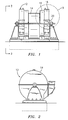
- FIG. 1 is a front view of an exemplary rotary coal pulverizer (duplex model) which can employ a crusher block assembly constructed in accordance with the present invention therein mounted on the center shaft at two locations;
- FIG. 2 is a side view of the rotary coal pulverizer of FIG. 1 , illustrating the output from the fan section of the pulverizer;
- FIG. 3 is an enlarged localized partial cross-sectional view of a portion of the exemplary rotary coal pulverizer of FIG. 1 , illustrating the grid cooperating with the swing hammers in the grinding section;
- FIG. 4 is a side cross-sectional view of a portion of the crushing chamber of FIG. 1 , showing the relationship between an exemplary prior art crusher block assembly and a plurality of swing hammers rotatable about the center shaft;
- FIG. 5 a is a top view of an exemplary prior art crusher block assembly, showing the adjustment mechanism attached to a yoke assembly, which is connected to the side supports, which in turn connect the crusher block to the assembly;
- FIG. 5 b is a side elevation view of the exemplary prior art crusher block assembly of FIG. 5 a , showing the adjustment mechanism attached to a yoke assembly, which is connected to the side supports, which in turn connect the crusher block to the assembly;
- FIG. 6 a is a top view of a first representative embodiment of a crusher block assembly in accordance with the present invention, showing an adjustment mechanism connected to a yoke assembly, which is joined directly to a crusher block;
- FIG. 6 b is a side elevation view of the crusher block assembly of FIG. 6 a in accordance with the present invention, showing an adjustment mechanism connected to a yoke assembly, which is joined directly to a crusher block, and also showing the grid;
- FIG. 7 a is a top view of a crusher block of the crusher block assembly of FIG. 6 a in accordance with the present invention, showing the flange with a pair of bores for attachment with the yoke assembly, as well as the pair of tabs on the lateral sides for attachment to the side supports;
- FIG. 7 b is a side elevation view of the crusher block of FIG. 7 a in accordance with the present invention, showing the elevation of the flange and bore, as well as the inboard face for cooperating with the swing hammers;
- FIG. 8 is a perspective view of a the crusher block assembly of FIG. 6 a in accordance with the present invention, showing the direction of motion during adjustment of the crusher block assembly;
- FIG. 9 a is a top view of another exemplary embodiment of a crusher block constructed in accordance with the present invention, showing slots on its sides in hidden lines;
- FIG. 9 b is a front elevation view of the crusher block of FIG. 9 b , showing the inboard face with the slots on the sides of the crusher block in hidden lines;
- FIG. 9 c is a side elevation view of the crusher block of FIG. 9 a of the present invention showing one of the slots;
- FIG. 10 a is a top view of the crusher block of FIG. 9 a , showing the slots in the crusher block accommodating the respective tabs of the side supports;
- FIG. 10 b is a cross-sectional side elevation view of the crusher block of FIG. 9 a , showing one of the slots in the crusher block accommodating a tab of the respective side support.
- FIGS. 1 and 2 illustrate the general location of a presently preferred embodiment of a crusher block assembly constructed in accordance with the present invention employed in an exemplary rotary coal pulverizer 12 .
- Pulverizer 12 is known as a horizontal type high speed coal mill and is closely based on a duplex model ATRITA® pulverizer sold commercially by Babcock Power Inc. However, this should not be interpreted as limiting the present invention in any way, as many types of particulate size reduction systems employ similar elements and are suitable for use with the present invention.
- the duplex model is essentially two single models side by side. It should be readily apparent that a crusher block assembly constructed in accordance with the present invention may also be disposed in a single model. For purposes of ease and convenience in describing the features of the present invention, only a single side of the duplex model is discussed herein.
- pulverizer 12 consists essentially of a crusher-dryer section 14 , a grinding section 16 and a fan section 18 .
- a center shaft 20 extends through the pulverizer 12 and defines an axis of rotation.
- axially inner and “axially outer” refer to the distance along or parallel to the axis defined by center shaft 20
- the “axially innermost” section in pulverizer 12 is crusher-dryer section 14 .
- raw coal and primary air enter the crusher-dryer section 14 .
- Swing hammers 22 mounted on a wheel assembly that is driven by center shaft 20 , along with impact liners (not shown), operate to crush the coal against a grid 32 .
- High temperature primary air is used to flash dry any surface moisture on the coal, which helps minimize the effect of moisture on coal capacity, coal fineness, and power consumption, among other things. As the high-temperature primary air evaporates moisture from the coal, the temperature of the coal-air mixture is reduced, which significantly reduces the risk of fires within the pulverizer.
- the major grinding components in grinding section 16 include stationary pegs 24 and grinding clips 26 disposed on a rotating wheel assembly 28 mounted on center shaft 20 .
- Pegs 24 are arranged on interior grinding section wall 30 in spaced apart relationships with respect to each other. Furthermore, pegs 24 are perpendicular with respect to wall 30 , and opposed to clips 26 , but are spaced so that clips 26 and pegs 24 do not contact each other during rotation of wheel assembly 28 .
- Wheel 28 is driven by center shaft 20 , preferably at a relatively high rate of speed.
- the turbulent flow and impact momentum on particles, caused by the movement of clips 26 and pegs 24 create a particle-to-particle attrition, which further reduces the size of the coal particles received from crusher-dryer section 14 .
- Coal particles ground to an acceptably small size then pass from grinding section 16 and into fan section 18 , where the coal fines are entrained into a flow out of pulverizer 12 for use in other processes, such as combustion.
- FIG. 4 shows a portion of crusher-drier section 14 in detail. Relatively large coal particles enter pulverizer 12 through the top portion of crusher-drier section 14 . Large particles are crushed between rotating swing hammers 22 and stationary breaker plate 48 . Coal particles that have been broken down to a size typically around 1 ⁇ 4 inch (6.35 mm) pass through grid 32 into an area between grid 32 and the outer housing of crusher-drier section 14 . From there, coal particles are conveyed into grinding section 16 , as described above.
- prior art crusher block assembly 34 is disposed between breaker plate 48 and grid 32 .
- the grinding surfaces of breaker plate 48 , swing hammers 22 , and crusher block assembly 34 wear down.
- the wear increases the gaps between the grinding faces of swing hammers 22 and the grinding surfaces of breaker plate 48 and crusher block assembly 34 , making it more difficult to reduce coal particles down to the desired size for passage through grid 32 . Therefore, crusher block assembly 34 is connected to an adjustment mechanism 42 which can be used to move crusher block assembly 34 closer and closer to rotating swing hammers 22 to maintain the desired clearance as the grinding face 36 of crusher block assembly 34 wears down.
- adjustment mechanism 42 includes two pins or bolts extending through the outer housing of crusher-drier section 14 , and attaching to prior art yoke assembly 38 .
- prior art yoke assembly 38 can be shifted back and forth parallel to the bolts/pins by rotating the bolts/pins of adjustment mechanism 42 .
- Yoke assembly 38 holds rod 46 , which extends into a side support 40 on either lateral end of crusher block assembly 34 .
- Recesses 41 defined in each side support receives a tab 51 of crusher block 50 .
- the adjustment mechanism 42 is advanced to move the crusher block 50 in an inboard direction toward the operating swing hammers until contact is established between the two components.
- the operator hears a “ticking” sound at this point.
- the operator attempts to “back off” the crusher block to an acceptable distance from the moving swing hammers, leaving, for example a quarter inch gap, and, to stop the “ticking.”
- To stop the ticking it is possible that the operator backs out the crusher block a greater distance than desired due to the manufacturing tolerances between the recesses in the side supports and the crusher block being too great, tending to cause some “lag” in the crusher block 50 following the side supports 40 in the outboard direction.
- a larger gap results in decreased pulverizer output, and may also result in the crusher block being “cockeyed” so that an uneven gap is defined between the swing hammer and crusher block, causing uneven wear of the swing hammer, as well as the crusher block.
- the operator fails to carefully advance the crusher block toward the operating swing hammers, the operator runs the risk of interfering with the hammers' forward motion which can then result in hammer breakage, and possibly further damage.
- FIGS. 6 a - 8 illustrate a crusher block assembly 134 , or aspects thereof, constructed in accordance with the present invention, which reduces or eliminates the adjustment problems described above resulting from tolerancing problems.
- Crusher block 50 has an inboard face 136 for cooperating with swing hammers 22 , and an outboard face opposite inboard face 136 for attaching to adjustment mechanism 142 .
- FIG. 7 a - 7 b show crusher block 150 in isolation.
- Flange 152 extends from crusher block 150 opposite inboard face 136 .
- Two bores 154 extend through flange 152 and are dimensioned to accommodate a fastener, such as a typical bolt.
- Recess 158 (See FIG. 7 a ) accommodates tools used to install a fastener.
- Tabs 156 allow for connection to corresponding slots in side supports 140 .
- adjustment mechanism 142 connects to yoke assembly 138 .
- Yoke assembly 138 is joined directly to crusher block 150 by a pair of bolts extending through bores 154 in flange 152 .
- Side supports 140 are attached to crusher block 150 by tabs 156 .
- Side supports 140 serve as a mechanical stop and as a guide for adjusting the crusher block assembly 134 .
- the side supports 140 rest on the grid and are further guided by the upper housing side wear plates (not depicted).
- FIGS. 9 a - 9 c show crusher block 250 with slots 257 on its sides. Also shown are inboard face 236 , bores 254 , and recess 258 . Slots 257 accommodate tabs 256 of side supports 240 , as depicted in FIGS. 10 a and 10 b . Slots 257 and tabs 256 are configured to tolerate slight degrees of misalignment between the housing walls (e.g. 14 ) that can be present particularly in pulverizers that have been in service for several years. The configuration shown in FIGS. 9 a - 10 b thus allows for installation of new crusher block assemblies in older machines as well as newer machines.
- Crusher block 150 can be made from a variety of materials including cast iron, cast manganese steel, cast stainless steel, combinations of the foregoing materials, or any other suitable material. Cast stainless steel is a particularly advantageous material for use with coal having high sulfur content. Those skilled in the art will readily appreciate that the invention can be practiced with two bolts in two bores 154 , or with more or less bolts/bores without departing from the spirit and scope of the invention. Moreover, while crusher block 150 has a single flange 152 with bores 154 , it is possible to use a separate flange for each bore. Similarly, while crusher block assembly 134 has been described above using bolts in bores 154 to connect yoke assembly 138 to crusher block 150 , any suitable fasteners or joining method can be used without departing from the spirit and scope of the invention.
- a method for adjusting clearance between a swing hammer and a crusher block in a particulate size reduction system.
- the method includes the steps of operating a particulate size reduction system by rotating at least one swing hammer mounted on a wheel assembly about a center shaft mounted in a crushing chamber.
- the at least one swing hammer includes a first crushing face.
- the method further includes disposing an inboard face of a crusher block proximate the at least one swing hammer and advancing the crusher block assembly toward the at least one swing hammer by adjusting an adjustment mechanism joined to the outboard face of the crusher block until the crusher block begins to contact the at least one rotating swing hammer.
- the method also includes retracting the crusher block assembly away from the at least one swing hammer using the adjustment mechanism to a predetermined distance.
- a particulate size reduction system (e.g. pulverizer 12 ) is operated by rotating at least one swing hammer (e.g. 22 ) mounted on a wheel assembly about a center shaft (e.g. 20 ) mounted in a crushing chamber (e.g. 14 ).
- An inboard face of (e.g. 136 ) of a crusher block (e.g. 150 ) is disposed proximate the swing hammer.
- the at least one swing hammer has a first crushing face for cooperating with the inboard face of the crusher block to crush particles such as coal particles.
- the crusher block assembly is advanced toward the at least one swing hammer by adjusting an adjustment mechanism (e.g. 142 ) joined to the outboard face of the crusher block until the crusher block begins to contact the at least one rotating swing hammer.
- an adjustment mechanism e.g. 142
- the crusher block assembly is retracted away from the at least one swing hammer to a predetermined distance using the adjustment mechanism.
- the large arrow in FIG. 8 shows the general direction of motion in the crusher block assembly as it is advanced and retracted during adjustment.
- the predetermined distance can be between about one eighth of an inch to about three eights of an inch. Preferably, the predetermined distance is about one quarter of an inch, however those skilled in the art will readily appreciate that the predetermined distance can be any distance suitable to produce the desired amount of particle size reduction.
- the adjustment mechanism can include two laterally displaced adjustable fasteners connected to the outboard face of the crusher block so that relative adjustment of one of the laterally displaced fasteners moves a first edge of the crusher block closer to the swing hammer than a second edge of the crusher block.
Abstract
Description
Claims (11)
Priority Applications (4)
| Application Number | Priority Date | Filing Date | Title |
|---|---|---|---|
| US11/818,574 US7748655B2 (en) | 2007-06-15 | 2007-06-15 | Crusher block assembly for particulate size reduction system |
| US12/545,550 US7913941B2 (en) | 2007-06-15 | 2009-08-21 | Crusher block assembly for particulate size reduction system |
| US29/388,211 USD660887S1 (en) | 2007-06-15 | 2011-03-25 | Crusher block for particulate size reduction system |
| US29/410,102 USD673984S1 (en) | 2007-06-15 | 2012-01-04 | Crusher block assembly for particulate size reduction system |
Applications Claiming Priority (1)
| Application Number | Priority Date | Filing Date | Title |
|---|---|---|---|
| US11/818,574 US7748655B2 (en) | 2007-06-15 | 2007-06-15 | Crusher block assembly for particulate size reduction system |
Related Child Applications (1)
| Application Number | Title | Priority Date | Filing Date |
|---|---|---|---|
| US12/545,550 Division US7913941B2 (en) | 2007-06-15 | 2009-08-21 | Crusher block assembly for particulate size reduction system |
Publications (2)
| Publication Number | Publication Date |
|---|---|
| US20080308660A1 US20080308660A1 (en) | 2008-12-18 |
| US7748655B2 true US7748655B2 (en) | 2010-07-06 |
Family
ID=40131405
Family Applications (4)
| Application Number | Title | Priority Date | Filing Date |
|---|---|---|---|
| US11/818,574 Expired - Fee Related US7748655B2 (en) | 2007-06-15 | 2007-06-15 | Crusher block assembly for particulate size reduction system |
| US12/545,550 Expired - Fee Related US7913941B2 (en) | 2007-06-15 | 2009-08-21 | Crusher block assembly for particulate size reduction system |
| US29/388,211 Active USD660887S1 (en) | 2007-06-15 | 2011-03-25 | Crusher block for particulate size reduction system |
| US29/410,102 Active USD673984S1 (en) | 2007-06-15 | 2012-01-04 | Crusher block assembly for particulate size reduction system |
Family Applications After (3)
| Application Number | Title | Priority Date | Filing Date |
|---|---|---|---|
| US12/545,550 Expired - Fee Related US7913941B2 (en) | 2007-06-15 | 2009-08-21 | Crusher block assembly for particulate size reduction system |
| US29/388,211 Active USD660887S1 (en) | 2007-06-15 | 2011-03-25 | Crusher block for particulate size reduction system |
| US29/410,102 Active USD673984S1 (en) | 2007-06-15 | 2012-01-04 | Crusher block assembly for particulate size reduction system |
Country Status (1)
| Country | Link |
|---|---|
| US (4) | US7748655B2 (en) |
Cited By (3)
| Publication number | Priority date | Publication date | Assignee | Title |
|---|---|---|---|---|
| US20110186664A1 (en) * | 2010-01-29 | 2011-08-04 | Scott Equipment Company | Dryer/Grinder |
| US20120174400A1 (en) * | 2005-09-23 | 2012-07-12 | Riley Power Inc. | Split fan wheel and split shroud assemblies and methods of manufacturing and assemblying the same |
| US20210260595A1 (en) * | 2018-07-10 | 2021-08-26 | Schenck Process Llc | High efficiency impact mill |
Families Citing this family (2)
| Publication number | Priority date | Publication date | Assignee | Title |
|---|---|---|---|---|
| CN112547273B (en) * | 2021-01-15 | 2021-09-07 | 郎溪县振达矿业有限责任公司 | Equipment for grinding and crushing ores |
| USD1004643S1 (en) | 2022-04-04 | 2023-11-14 | Xiaojian Ma | Can crusher |
Citations (11)
| Publication number | Priority date | Publication date | Assignee | Title |
|---|---|---|---|---|
| US850988A (en) * | 1905-11-24 | 1907-04-23 | Williams Patent Crusher & Pulv | Coal-crusher. |
| US2185331A (en) * | 1937-04-26 | 1940-01-02 | Universal Crusher Company | Pulverizer |
| US4326674A (en) | 1979-02-08 | 1982-04-27 | Halbach & Braun | Device for the homogenization of material to be crushed |
| US4848682A (en) * | 1988-05-31 | 1989-07-18 | Morris Scheler | Double bladed rock crusher |
| US4903904A (en) * | 1983-12-13 | 1990-02-27 | Richard Steimel | Comminuting device for turnings |
| US5257743A (en) | 1992-02-20 | 1993-11-02 | Brown Jr Charles K | Quarry pulverizer |
| WO1997039828A1 (en) | 1996-04-22 | 1997-10-30 | Taylor Woolhouse Limited | Improvement to a mineral crusher |
| WO1999047263A1 (en) | 1998-03-13 | 1999-09-23 | Cvr Holdings Pty. Ltd. | Improvements in roll crushers |
| US6237865B1 (en) | 1998-06-20 | 2001-05-29 | Neuenhauser Maschinenbau Gmbh & Co. Kg | Apparatus for screening and/or crushing screen materials |
| US6575303B1 (en) | 1998-10-08 | 2003-06-10 | Ai Enterprises, Inc. | Processing a product including aggregate materials and a volatile component |
| US7028931B2 (en) | 2003-11-03 | 2006-04-18 | Riley Power, Inc. | Dynamic ring classifier for a coal pulverizer |
Family Cites Families (2)
| Publication number | Priority date | Publication date | Assignee | Title |
|---|---|---|---|---|
| US2734686A (en) * | 1956-02-14 | oberhellmann | ||
| US2962233A (en) * | 1959-04-14 | 1960-11-29 | Poor & Co | Adjustable hammermill breakerplate |
-
2007
- 2007-06-15 US US11/818,574 patent/US7748655B2/en not_active Expired - Fee Related
-
2009
- 2009-08-21 US US12/545,550 patent/US7913941B2/en not_active Expired - Fee Related
-
2011
- 2011-03-25 US US29/388,211 patent/USD660887S1/en active Active
-
2012
- 2012-01-04 US US29/410,102 patent/USD673984S1/en active Active
Patent Citations (13)
| Publication number | Priority date | Publication date | Assignee | Title |
|---|---|---|---|---|
| US850988A (en) * | 1905-11-24 | 1907-04-23 | Williams Patent Crusher & Pulv | Coal-crusher. |
| US2185331A (en) * | 1937-04-26 | 1940-01-02 | Universal Crusher Company | Pulverizer |
| US4326674A (en) | 1979-02-08 | 1982-04-27 | Halbach & Braun | Device for the homogenization of material to be crushed |
| US4903904A (en) * | 1983-12-13 | 1990-02-27 | Richard Steimel | Comminuting device for turnings |
| US4848682A (en) * | 1988-05-31 | 1989-07-18 | Morris Scheler | Double bladed rock crusher |
| US5257743A (en) | 1992-02-20 | 1993-11-02 | Brown Jr Charles K | Quarry pulverizer |
| WO1997039828A1 (en) | 1996-04-22 | 1997-10-30 | Taylor Woolhouse Limited | Improvement to a mineral crusher |
| EP0912247B1 (en) | 1996-04-22 | 2000-11-08 | Taylor Woolhouse Holdings Limited | Improvement to a mineral crusher |
| WO1999047263A1 (en) | 1998-03-13 | 1999-09-23 | Cvr Holdings Pty. Ltd. | Improvements in roll crushers |
| US6237865B1 (en) | 1998-06-20 | 2001-05-29 | Neuenhauser Maschinenbau Gmbh & Co. Kg | Apparatus for screening and/or crushing screen materials |
| US6575303B1 (en) | 1998-10-08 | 2003-06-10 | Ai Enterprises, Inc. | Processing a product including aggregate materials and a volatile component |
| US7028931B2 (en) | 2003-11-03 | 2006-04-18 | Riley Power, Inc. | Dynamic ring classifier for a coal pulverizer |
| US7240868B2 (en) | 2003-11-03 | 2007-07-10 | Riley Power, Inc. | Dynamic ring classifier for a coal pulverizer |
Cited By (4)
| Publication number | Priority date | Publication date | Assignee | Title |
|---|---|---|---|---|
| US20120174400A1 (en) * | 2005-09-23 | 2012-07-12 | Riley Power Inc. | Split fan wheel and split shroud assemblies and methods of manufacturing and assemblying the same |
| US8615874B2 (en) * | 2005-09-23 | 2013-12-31 | Riley Power Inc. | Split fan wheel and split shroud assemblies and methods of manufacturing and assemblying the same |
| US20110186664A1 (en) * | 2010-01-29 | 2011-08-04 | Scott Equipment Company | Dryer/Grinder |
| US20210260595A1 (en) * | 2018-07-10 | 2021-08-26 | Schenck Process Llc | High efficiency impact mill |
Also Published As
| Publication number | Publication date |
|---|---|
| US7913941B2 (en) | 2011-03-29 |
| US20090308959A1 (en) | 2009-12-17 |
| USD673984S1 (en) | 2013-01-08 |
| US20080308660A1 (en) | 2008-12-18 |
| USD660887S1 (en) | 2012-05-29 |
Similar Documents
| Publication | Publication Date | Title |
|---|---|---|
| US7240868B2 (en) | Dynamic ring classifier for a coal pulverizer | |
| US7913941B2 (en) | Crusher block assembly for particulate size reduction system | |
| US7584918B1 (en) | Wear plate assembly for vertical rotor of a pulverizer | |
| US20080185466A1 (en) | Solids reduction processor | |
| CN112619788A (en) | Hammering type crusher | |
| US20090250538A1 (en) | Swing hammer for particulate size reduction system | |
| US5845856A (en) | Pin mill type crusher | |
| US7311281B2 (en) | Grinding and impeller clip for a coal pulverizer | |
| CN108339655B (en) | Rotary nozzle structure of medium-speed coal mill | |
| US7306178B2 (en) | Grinding chamber side liner for a coal pulverizer | |
| JP2685820B2 (en) | Roller type crusher | |
| US7309037B2 (en) | Stationary peg for a coal pulverizer | |
| CN209576876U (en) | A kind of hammer mill of self-cleaning | |
| CA2342105A1 (en) | Mill with quick change, unitized, dynamic elements | |
| US8425116B2 (en) | Split guide bushing for vertical pulverizers | |
| JP2690753B2 (en) | Vertical roller mill | |
| KR100854753B1 (en) | Air curtain cap for preventing inflow pulverized coal | |
| JP2003117415A (en) | Vertical crusher | |
| KR101858245B1 (en) | Apparatus for sealing air of bowl mill | |
| US20130146695A1 (en) | Journal brush seal assemblies | |
| JPH11276919A (en) | Roller mill | |
| JP3112566B2 (en) | Roller mill | |
| CN106111275A (en) | A kind of turn atomizer for the poorest of chemical industry | |
| JP3072894B2 (en) | Crushing pin | |
| JP2740536B2 (en) | Hard roller mill |
Legal Events
| Date | Code | Title | Description |
|---|---|---|---|
| AS | Assignment |
Owner name: RILEY POWER, INC., MASSACHUSETTS Free format text: ASSIGNMENT OF ASSIGNORS INTEREST;ASSIGNORS:SCHMITZ, WILLIAM;VERGER, RICHARD N. DU;SMITH, DANIEL P.;AND OTHERS;REEL/FRAME:019693/0550;SIGNING DATES FROM 20070607 TO 20070620 Owner name: RILEY POWER, INC., MASSACHUSETTS Free format text: ASSIGNMENT OF ASSIGNORS INTEREST;ASSIGNORS:SCHMITZ, WILLIAM;VERGER, RICHARD N. DU;SMITH, DANIEL P.;AND OTHERS;SIGNING DATES FROM 20070607 TO 20070620;REEL/FRAME:019693/0550 |
|
| AS | Assignment |
Owner name: RILEY POWER INC., MASSACHUSETTS Free format text: RE-RECORD TO CORRECT THE NAME OF THE SECOND ASSIGNOR, PREVIOUSLY RECORDED ON REEL 019693 FRAME 0550.;ASSIGNORS:SCHMITZ, WILLIAM;DUVERGER, RICHARD N.;SMITH, DANIEL P.;AND OTHERS;REEL/FRAME:019729/0392;SIGNING DATES FROM 20070607 TO 20070620 Owner name: RILEY POWER INC., MASSACHUSETTS Free format text: RE-RECORD TO CORRECT THE NAME OF THE SECOND ASSIGNOR, PREVIOUSLY RECORDED ON REEL 019693 FRAME 0550;ASSIGNORS:SCHMITZ, WILLIAM;DUVERGER, RICHARD N.;SMITH, DANIEL P.;AND OTHERS;SIGNING DATES FROM 20070607 TO 20070620;REEL/FRAME:019729/0392 |
|
| AS | Assignment |
Owner name: BANK OF AMERICA, N.A., AS ADMINISTRATIVE AGENT,TEX Free format text: NOTICE OF GRANT OF SECURITY INTEREST IN PATENTS;ASSIGNOR:RILEY POWER INC.;REEL/FRAME:024505/0181 Effective date: 20100527 Owner name: BANK OF AMERICA, N.A., AS ADMINISTRATIVE AGENT, TE Free format text: NOTICE OF GRANT OF SECURITY INTEREST IN PATENTS;ASSIGNOR:RILEY POWER INC.;REEL/FRAME:024505/0181 Effective date: 20100527 |
|
| STCF | Information on status: patent grant |
Free format text: PATENTED CASE |
|
| FPAY | Fee payment |
Year of fee payment: 4 |
|
| FEPP | Fee payment procedure |
Free format text: 7.5 YR SURCHARGE - LATE PMT W/IN 6 MO, LARGE ENTITY (ORIGINAL EVENT CODE: M1555) |
|
| MAFP | Maintenance fee payment |
Free format text: PAYMENT OF MAINTENANCE FEE, 8TH YEAR, LARGE ENTITY (ORIGINAL EVENT CODE: M1552) Year of fee payment: 8 |
|
| FEPP | Fee payment procedure |
Free format text: MAINTENANCE FEE REMINDER MAILED (ORIGINAL EVENT CODE: REM.); ENTITY STATUS OF PATENT OWNER: LARGE ENTITY |
|
| LAPS | Lapse for failure to pay maintenance fees |
Free format text: PATENT EXPIRED FOR FAILURE TO PAY MAINTENANCE FEES (ORIGINAL EVENT CODE: EXP.); ENTITY STATUS OF PATENT OWNER: LARGE ENTITY |
|
| STCH | Information on status: patent discontinuation |
Free format text: PATENT EXPIRED DUE TO NONPAYMENT OF MAINTENANCE FEES UNDER 37 CFR 1.362 |
|
| FP | Lapsed due to failure to pay maintenance fee |
Effective date: 20220706 |