US7751441B2 - Method for exchanging data packets between two service providers of a radiotelephony transmission system - Google Patents
Method for exchanging data packets between two service providers of a radiotelephony transmission system Download PDFInfo
- Publication number
- US7751441B2 US7751441B2 US10/415,866 US41586603A US7751441B2 US 7751441 B2 US7751441 B2 US 7751441B2 US 41586603 A US41586603 A US 41586603A US 7751441 B2 US7751441 B2 US 7751441B2
- Authority
- US
- United States
- Prior art keywords
- data
- packet
- pdu
- pus
- field
- Prior art date
- Legal status (The legal status is an assumption and is not a legal conclusion. Google has not performed a legal analysis and makes no representation as to the accuracy of the status listed.)
- Expired - Fee Related, expires
Links
Images


Classifications
-
- H—ELECTRICITY
- H04—ELECTRIC COMMUNICATION TECHNIQUE
- H04L—TRANSMISSION OF DIGITAL INFORMATION, e.g. TELEGRAPHIC COMMUNICATION
- H04L1/00—Arrangements for detecting or preventing errors in the information received
- H04L1/12—Arrangements for detecting or preventing errors in the information received by using return channel
- H04L1/16—Arrangements for detecting or preventing errors in the information received by using return channel in which the return channel carries supervisory signals, e.g. repetition request signals
- H04L1/1607—Details of the supervisory signal
- H04L1/1614—Details of the supervisory signal using bitmaps
-
- H—ELECTRICITY
- H04—ELECTRIC COMMUNICATION TECHNIQUE
- H04W—WIRELESS COMMUNICATION NETWORKS
- H04W28/00—Network traffic management; Network resource management
- H04W28/02—Traffic management, e.g. flow control or congestion control
- H04W28/06—Optimizing the usage of the radio link, e.g. header compression, information sizing, discarding information
-
- H—ELECTRICITY
- H04—ELECTRIC COMMUNICATION TECHNIQUE
- H04W—WIRELESS COMMUNICATION NETWORKS
- H04W80/00—Wireless network protocols or protocol adaptations to wireless operation
-
- H—ELECTRICITY
- H04—ELECTRIC COMMUNICATION TECHNIQUE
- H04W—WIRELESS COMMUNICATION NETWORKS
- H04W92/00—Interfaces specially adapted for wireless communication networks
- H04W92/02—Inter-networking arrangements
Definitions
- data are transmitted from a base station to a mobile radiotelephone station in packet form via the air interface or are transmitted in the opposite direction.
- a connection control protocol is situated in the base station and the mobile radiotelephone station, whereby one purpose of the connection control protocol is to determine, on the basis of control data, whether and which data packets have been lost during the transmission. These control data must be added to each packet sent by the connection control protocol.
- a number of packets can be transmitted within what is referred to as a transmission interval. The number of packets to be transmitted can vary from interval to interval. This allows different data transmission rates.
- the present invention proposes a method which makes is possible to reduce the number of packets that are transmitted via the air interface, by transmitting larger, rather than more, packets within a transmission interval. This does not affect the possibility of varying the data transmission rates.
- UMTS Universal Mobile Telecommunication System
- UMTS UE User Equipment
- UMTS Node B a base station
- RNC radio network controller
- GSN GPRS Support Node
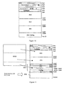
- FIG. 2 shows the structure of the UE, the node B and the RNC, whereby only the layers 1 and 2 , which are referred to as physical layer and link layer (here composed of MAC and RLC) in the OSI model, can be seen.
- the radio resource control RRC (not shown in FIG. 2 ) is situated above the layer referred to as RLC.
- RLC Radio Resource Control
- user data to be transmitted are either directly given to the RLC layer from higher layers or from the packet data convergence protocol layer which is not shown in FIG. 2 and which is not relevant for the present invention.
- the respective layer processes the data in the transmitter and forwards the data to the next layer therebelow.
- the RLC layer forwards the packets to the medium access control MAC which, in turn, processes the packets and subsequently forwards them to the layer 1 .
- the packets that have been received by a higher layer are referred to as SDUs (Service Data Units) and the packets that are forwarded to layers that are situated below it are referred to as PDUs (Packet Data Unit).
- SDUs Service Data Units
- PDUs Packet Data Unit
- Layer 1 transmits the data via the air interface to the base station node B in which the layer 1 is also contained. Layer 1 transmits the received packets via the fixed network connection to the MAC in the RNC which, after the packets have been processed, forwards the packets to the RLC which finally forwards the packets to the higher layers.
- FIG. 3 shows the connection layer RLC and the medium access control MAC.
- RLC connection layer
- the RLC is composed of a number of units which can run in different modes, whereby a number of units can run in the same mode.
- TR mode transparent mode
- control data are not added to the packets that have been received from higher layers. Therefore, this mode is not relevant for the present invention.
- an unacknowledged mode the packets (SDUs) received from higher layers are segmented and combined into larger packets.
- a sequence number is added to the packets (PDUs) that are subsequently forwarded to the MAC.
- PDUs packets
- the size of the PDUs, in which the SDUs are segmented or, respectively, combined, varies and is not prescribed by the MAC layer.
- the application of the present invention with respect to this mode is conceivable in order to facilitate the realization in the software since the packets could be presegmented and cannot be segmented at the moment anymore when the size of the PDU is prescribed by MAC.
- the SDUs are segmented or, respectively, combined into packets of equal size, named payload units (PUs).
- PUs payload units
- the PUs In order to make it possible for the received RLC unit to correctly assemble the original SDUs which are forwarded from higher layers to the RLC unit, the PUs have indicators which inform the received RLC unit as to where an SDU ends within a segment. These indicators are referred to as length indicators.
- a bit of information indicating whether a data packet or a control packet is concerned, a sequence number, what is referred to as control data extension information (HE) indicating whether the next octet contains an aforementioned length indicator or already contains user data, and what is referred to as an polling bit that can be used for the reception acknowledgement mechanism, is additionally added to each segment.
- the D/C and the P field are not relevant for the present invention.
- FIGS. 4 a and 4 b show the two PDUs according to the current prior art. In PDU 4 b , an SDU ends in the PU, so that the third octet of the PDU is a length indicator.
- the RLC is informed by MAC about the number of the PDUs to be transmitted via air in the next transmission interval.
- the size of the PDUs is static.
- RLC can determine the PU size on the basis of the size of the PDU since the size of the PDU precisely corresponds to the PU size+2 bytes. If an SDU ends within a PDU or, respectively, PU and if the remaining space of this PDU or, respectively, PU is filled with padding, a further length indicator, whose fixed value indicates that the PU has been filled with padding, is added to the PDU or, respectively, PU.
- FIG. 4 b shows a PU in which an SDU ends, the remainder of the PDU, however, is filled with a first segment of a second SDU.
- the first bit from the right is an extension bit (E) indicating whether the LI is followed by a further LI or user data. Therefore, only one LI is necessary.
- FIG. 4 c shows a PDU in whose PU an SDU ends and the remainder of the PU must be filled with padding. Two LIs are necessary as a result. One LI that indicates that an SDU ends within the PU and a second one that indicates that the PU has been filled with padding.
- the PDUs are forwarded to the MAC via logical connections and are subsequently transmitted via the air interface.
- the MAC forwards the packets to the RLC via the logical connections.
- the reception of a packet is acknowledged in the acknowledged mode by the receiving RLC unit.
- an RLC unit can send an acknowledgement for all packets received since the last acknowledgement has been sent after a timer has expired.
- the transmitting RLC unit in a packet via an additional bit of information (polling bit), can request from the receiving RLC unit to return an acknowledgment.
- Packets that have not been acknowledged by the receiving side are transmitted again by the transmitting RLC unit. For this purpose, all transmitted PDUs must be stored in the RLC unit until a positive reception acknowledgement is received. Since the packet size of all stored packets is equal and since the MAC always requests a number of packets of this size, the packets that have to be sent again can be forwarded to the MAC at any time without problems. As a result, it can occur that a PDU having the sequence number 5 is sent after a PDU having the sequence number 10 and the PDU having the sequence number 11 follows thereafter.
- the smallest possible transmission rate for a logical channel is determined via the PU size. This transmission rate can be higher depending on the number of the PDUs indicated by MAC.
- ANNEX A describes the concept as has been proposed for the 99 version and as it was contained in the specification of the RLC TS 25.322 v3.0.0. This has the advantage that it is still possible to vary the data transmission rates in that the number of PUs is determined per PDU, and the control data (sequence number, D/C field, HE field and P field) have to be transmitted only once for the one, larger PDU via the air interface. Then, the sequence number should only indicate the sequence number of the first PU. The sequence numbers of the following PUs can be calculated therefrom.
- the space taken by the control data extensions had to be subtracted from the size of the PU. Therefore, it was not possible, without further ado, to transmit once again the already transmitted PUs since they possibly did not require a control data extension given the repeated transmission. Therefore, the size of the PU was no longer equal to the size of the PU that was transmitted for the first time.
- the basic condition for the present invention was that SDUs received from higher layers were to be presegmented in PUs and these PUs were to be stored in the transmitting RLC unit and no longer varied until the reception acknowledgement by the receiving RLC unit even when they had to be transmitted again.
- the length indicators indicating the end of a SDU within a PU are purposefully part of the PU since they do not change either.
- the present invention differentiates between two different types of padding, the padding within a PU, referred to as PU padding in the following, and the padding within a PDU, referred to as PDU padding in the following.
- PDU padding refers to the padding within a PDU and is necessary, for example, since the PDU holds a number n of PUs and the corresponding control data (D/C, HE, P field and sequence number), and space that is smaller than a PU size is still remaining in the PDU, so that PDU padding must be added. Whether a PDU contains such a PDU padding can be determined with the aid of the knowledge of the PDU size and the size of the control data. As a result, additional signaling is not necessary.
- PU padding refers to the padding within a PU and is necessary, for example, since anSDU ends in a PU and does not completely fill the SDU and since a segment of a further SDU is not inserted.
- the special length indicator which indicates in the currently valid version that the PDU contains padding, is added to the PU. Therefore, it indicates that the remainder of the PU is padding and not the remainder of the PDU.
- the essence of the present invention is a length indicator bitmap (LI bitmap) contained in a PDU when more than one PU is contained in the PDU.
- the LI bitmap can be 8 or 16 bits long.
- the number of the PUs per PDU is limited to 8 or, respectively, 16 when an 8 bit long or, respectively, 16 bit long LI bitmap is selected.
- An LI bitmap as shown in FIG. 5 would be particularly advantageous in that the last bit, an extension bit (E-bit; extension bit), indicates whether a further LI bitmap follows in the next octet.
- the LI bitmaps vary with respect to the number of the PUs to be transported. Every bit of the LI bitmap indicates whether a PU allocated to the bit starts with an LI or with user data.
- Another important part of the present invention is the following definition: If PUs that have to be repeatedly transmitted and PUs that are transmitted for the first time are to be transmitted in a PDU, it is defined where the PUs to be repeatedly transmitted and where the PUs to be transmitted for the first time are contained in the PDU. For example, one possibility would be that the PUs that have to be repeatedly transmitted must be inserted first into the PDU.
- a control data extension is additionally inserted for each of the PUs that have to be repeatedly transmitted. It contains a sequence number, extension information, (e.g., one bit), which indicates whether another control data extension follows and contains a field that can be used for purposes that have not yet been specified.
- the present invention includes a regulation that defines which sequence numbers are allocated to which PUs. For example, a possible regulation would be to always transport the sequence numbers, which are allocated to the PUs to be repeatedly transmitted, in the control data extension and to transport the sequence number of the first PU, which is to be transmitted in the correct order, in the first sequence number field.
- the sequence number entered in the first sequence number field is the one designating the next PU to be transmitted for the first time.
- the sequence numbers of the PUs to be repeatedly transmitted are transported in the control data extensions.
- the first PU to be transmitted for the first time is inserted into the PDU after the PUs to be repeatedly transmitted. This PU in the PDU is followed by further PUs that are to be transmitted for the first time.
- a sequence number must not be inserted for them since the sequence number of these
- PUs is always increased only by one. If an entire PDU is filled with PUs that are repeatedly transmitted and these PUs are in an order, the PDU is set up as if a PDU is concerned that is exclusively filled with PUs that have not yet been sent.
- the number of PUs to be transmitted for the first time and the number of the PUs to be repeatedly transmitted are requested by the MAC at the RLC, so that the MAC can select an ideal combination of the number and size of the PDUs.
- the RLC generates PUs that only contain PU padding if the MAC demands a PDU from the RLC that is larger than the PUs available for the transmission and the space to be filled in the PDU is larger than a PU.
- a sequence number is not allocated to such a PU generated by the RLC and the PU is ignored or, respectively, deleted on the receiver side.
- FIG. 1 shows a block diagram schematic of a third generation (UMTS) mobile radio telephone system.
- UMTS third generation
- FIG. 2 shows a block diagram of the physical and link layers of the user equipment, base station and radio network controller of the mobile radio telephone system from FIG. 1 .
- FIG. 3 shows details of the connection layer and medium access control of the components from FIG. 2 .
- FIGS. 4A through 4C show different packet data units as is known in the prior art.
- FIG. 5 is a simple representation of a length indicator bitmap contained in a packet data unit.
- FIG. 6 is a schematic representation of the multiple payload units segmented from a service data unit.
- FIG. 7 shows an exemplary embodiment of the present invention wherein a service data unit has been segmented into four payload units.
- FIG. 8 shows an alternative embodiment of the present invention.
- FIG. 9 shows a simple block diagram representation of a control data extension which may be added to a packet data unit.
- FIG. 10 shows a block diagram representation of a packet data unit that is ready for forwarding to a respective medium access control.
- FIG. 11 shows another alternative embodiment of the present invention.
- the exemplary embodiments are based on a connection as shown in FIG. 2 . It is assumed that the AM RLC unit has received a packet of the size of 100 bytes from the appertaining radio bearer 3 . Given the setup of the radio bearer 3 , it has been determined for the corresponding AM RLC unit of the transmitter and of the receiver that the PUs should have a size of 30 bytes.
- the transmitter and receiver can be either RNC or UE.
- the RRC which are situated above the RLC layers, exchange bits of information on the basis of which the respective RRC layer configures the other layers below it.
- the PU size is not calculated from the PDU size, which is prescribed by MAC, but is determined by the RRC layer.
- the SDU 1 now is segmented into four PUs, PU 1 to PU 4 .
- the four PUs receive the sequence numbers 10 to 13.
- the first three PUs are completely filled with data.
- the fourth PU only contains 10 bytes of the SDU 1 .
- the first LI indicates that the SDU 1 ends after 10 bytes after the LI fields, the following extension bit E 1 indicates that another LI field follows. In this example, a bit set to one indicates that a further LI follows.
- the second LI indicates that the remainder of the PU contains padding (PU padding) since no further data is contained therein.
- the following extension bit E 2 is set to 0 since another LI field does not follow.
- the four PUs are stored in the AM RLC entity.
- the MAC For each logical channel, (the logical channels 1 to 3 in this example), the MAC now informs the RLC about the desired size regarding the RLC PDUs and about the desired number of PDUs of this size that the MAC wishes to receive from the corresponding RLC unit. On the basis of these parameters, the MAC adjusts the data rate for each logical channel at the time of the request with respect to the PDUs.
- the selection of the number and size of the PDUs is based on the MAC requesting the number of the PUs or, respectively, the memory occupied by them, which are to be transmitted for the first time from the AM RLC unit, and also on requesting the number of the PUs or, respectively, memories occupied by them, which are to be repeatedly transmitted from the AM RLC unit.
- the MAC Given the setup of the radio bearer, the MAC has also been informed about possible combinations of RLC sizes and the number which it can use for transmitting the data. It is assumed for all examples that the following combinations are available to the MAC:
- the AM RLC unit communicated to the MAC that four PUs are to be transmitted for the first time and that PUs are not to be repeatedly transmitted. It is also assumed that the MAC decides to simultaneously get rid of the four PUs. If the MAC wishes to transmit four PUs of 30 bytes each, it can select between the combination 4 and the combination 5. Combination 4 corresponds to a combination as it can also be used in the 99 version.
- Each PDU has exactly one PU. Ideally, the PDU size is selected such that the PDU can contain the PU and the sequence number, as well as the header extension HE and the polling bit P and D/C field (see FIG. 4 a ). The PU size is 30 bytes; sequence number, HE, P and D/C field require 2 bytes in total, so that the PDU size is ideally 32 bytes. Therefore, 128 bytes must be transmitted in order to transmit all four PUs.
- the RLC AM unit forms four PUs, PDU 1 to PDU 4 , from the four PUs (see FIG. 7 ).
- the D/C field is set to one since the data represent user data.
- the P field can be set to one when the receiving AM RLC unit is to acknowledge the reception of the already transmitted PUs.
- the HE field is set to zero since useful data follow after the HE field.
- the PDU 4 the HE field is followed by length indicators, so that the HE field is set to one.
- the layer 1 forwards the data to the MAC which forwards the four PDUs again to the AM RLC unit.
- the order of the PUs can be recognized on the basis of the sequence number.
- the AM RLC unit recognizes whether the HE field is followed by user data or length indicators. In the RLC PDUs 1 to 3 , the HE field indicates that a LI bitmap or LI field does not follow.
- the receiving AM RLC unit additionally recognizes that an LI bitmap is not contained, so that only 1 PU fits into the PDU.
- the AM RLC unit knows the PU size and removes a correspondingly sized segment after the first two bytes of the PDU, whereby the bytes correspond to the PUs.
- the HE field is set to one in the RLC PDU 4 .
- the AM RLC unit analyzes LI 1 and thus receives the information that the SDU 1 ends after the first 10 bytes after the LIs.
- the first extension bit is set to one, so that the AM RLC unit recognizes that a further LI follows.
- This second LI informs the AM RLC unit that the remainder of the PU can be ignored since it is filled with PU padding.
- the following extension bit E 2 is set to zero, so that the AM RLC unit knows that the user data now follow.
- the AM RLC unit subsequently adds the missing 10 bytes of user data to the other three PUs, so that the original SDU 1 results again and is forwarded via the radio bearer 3 to the higher layers.
- the AM RLC unit forms one single PDU of the size of 123 bytes (see FIG. 8 ).
- the last bit of the third byte contains the extension bit which indicates whether a further LI bitmap or the first PU follows which, in this case is set to zero, for example, in order to indicate that a further LI bitmap does not follow.
- Each bit of the seven bit long LI bitmap indicates whether the corresponding PU starts with an LI or only contains user data.
- the bit all the way to the right is allocated to the first PU that is inserted into the PDU and the bit all the way to the left is allocated to the PU inserted at the seventh location.
- the four PUs 1 to 4 are inserted into the PDU, so that the first four bits from the right of the LI bitmap are used.
- PU 4 is the only one of the four PUs starting with an LI. Therefore, the fourth bit of the LI bitmap from the right is set to 1.
- RLC forwards the PDU to the MAC and the PDU is finally transmitted via the air interface.
- the layer 1 forwards the data to the MAC which subsequently forwards the PDU to said AM RLC unit and also informs said AM RLC unit about the size of the PDU.
- the AM RLC unit knows which sequence number must be allocated to the first PU. All further PUs receive sequence numbers in the order they are contained in the PDU, whereby the sequence numbers respectively increase by one.
- the AM RLC unit recognizes that the third byte contains an LI bitmap.
- the AM RLC unit recognizes that no further LI bitmap follows but the first PU.
- the AM RLC unit determines which of the PUs start with an LI.
- the fourth bit from the right is set to one.
- the AM RLC unit removes the PUs from the PDU and combines the first three PUs since these contain only user data.
- the first byte of the fourth PU communicates to the AM RLC unit that the SDU 1 ends after the first ten bytes after the LIs.
- the extension bit E 1 communicates to the AM RLC unit that another LI follows. This LI 2 indicates that the remainder of the PU is to be ignored.
- the corresponding extension bit E 2 indicates that user data follow.
- the AM RLC unit takes the following ten bytes, adds them to the PUs 1 to 3 , so that the original SDU 1 results.
- the AM RLC unit subsequently forwards the SDU 1 to the higher layers.
- the first transmission of a PDU failed.
- a sequence number having the value five is allocated to the PU.
- the PUs remain stored in the AM RLC unit until a positive reception acknowledgment is received. It is also assumed that the repeated transmission of this PDU has been requested by the receiving AM RLC unit.
- the SDU 1 has been segmented into the PUs 1 to 4 , whereby the sequence numbers 10 to 13 have been allocated to them.
- the MAC received the information from the AM RLC unit that four PUs must be transmitted for the first time and that one PU must be transmitted again. It is also assumed that the MAC wishes to transmit four PUs.
- the MAC now ideally selects a combination for the data transmission which makes it possible to transmit the PUs, which are to be repeatedly transmitted, alone in a PDU. This is expedient since the PUs to be repeatedly transmitted normally are not in the same order with the other PUs to be transmitted. If these PUs are transmitted in a PDU, additional control data extensions must be added to the PDU.
- the MAC would receive the information from the AM RLC unit that a PU is to be transmitted again. Subsequently, the MAC would ideally select the fourth combination since it wishes to transmit four PUs, whereby one of them must be repeatedly transmitted. Therefore, the PUs 0 to 3 are packed into four PUs 1 to 4 . PDU 1 carries PU 0 and the value of the sequence number is set to 5. The PDUs 2 to 4 contain the PUs 1 to 3 and the sequence numbers are set to the values 10 to 12. Given the next request, the MAC transmits the PU 4 . The PDUs are forwarded to the MAC and are finally transmitted via the air interface.
- the AM RLC unit evaluates the control data and recognizes on the basis of the control data that the PUs are not in the correct order.
- the control data are evaluated as described in the first example. If it is assumed that the PU 0 was the last missing segment of an SDU 0 , this SDU 0 is assembled and forwarded to the higher layers. The SDU 1 is not assembled and forwarded to the higher layers until the PU 4 has been transmitted. In total, 128 bytes are required for the transmission of the PUs 0 to 3 .
- the MAC received the information from the AM RLC unit that four 4 PUs must be transmitted for the first time and that one PU is to be repeatedly transmitted. It is assumed that the MAC wishes to transmit four PUs and selects a combination for this purpose wherein a number of PUs, which are not in the correct order, are transmitted in a PDU. This means for this example that the MAC selects the combination 5.
- FIG. 10 shows the PDU that is forwarded to the MAC.
- the sequence number 1 of the PDU contains the value 10 since the first PU is in the correct order PU 1 which has the sequence number 10 allocated.
- D/C and P field are set as described above.
- a value is allocated to the HE field which indicates that a control data extension containing the sequence number 2 of the PU 0 follows. In this example, this value is 2.
- the control data extension (see FIG.
- the value 5 is allocated to the sequence number 2; namely, the sequence number of the PU 0 .
- the SN-E bit indicates that the control data extension is followed by the LI bitmap.
- the value 0, for example is allocated to the SN-E bit. Therefore, five bytes are occupied of the PDU having the original size of 123 bytes. As a result, only three PUs of the size of 30 bytes fit into the PDU.
- the receiver side can allocate the sequence numbers of the control data extension to the PUs to be repeatedly transmitted.
- the PUs to be repeatedly transmitted here the PU 0
- the PUs 1 and 2 follow.
- the remainder of the PDU is occupied with padding.
- the PDU is forwarded to the MAC and is finally transmitted via the air interface.
- the PDU is handed to the top through the layers where it finally arrives at the AM RLC unit.
- the AM RLC unit receives the information from the first sequence number that the number 10 must be allocated to the first PU in the correct order.
- the AM RLC unit recognizes that a control data extension follows. On the basis of the control data extension, it receives the information from the sequence number 2 that the sequence number 5 is allocated to the first PU to be repeatedly transmitted. Due to the rule which determines where the PU can be found within the PDU, the AM RLC unit knows which PU needs the sequence number allocated. In this example, the PUs to be repeatedly transmitted are inserted first into the PDU. Therefore, the sequence number 2 is allocated to the PDU. Besides, the AM RLC unit receives the information from the E-SN field that the control data extension is followed by the LI bitmap.
- the AM RLC unit derives from the LI bitmap which of the PUs, namely all PUs contained in the PDU, starts with the LI field.
- the MAC informs the AM RLC unit about the PDU size given the transfer of the PDU.
- the AM RLC unit can determine the size of these control data due to the above-described evaluation of the control data. In this case, the size of the control data is five bytes.
- the AM RLC unit thus knows that three PUs are contained at a maximum and that the remainder of the PDU has been filled with PUD padding. Therefore, the AM RLC unit can correctly unpack the PDU.
- an SDU 2 has the size of 80 bytes. Therefore, the SDU is segmented into three PUs, PU 5 to PU 7 , whereby PU 5 and PU 7 only contain user data, so that LI fields are not inserted.
- PU 7 starts with a first LI 1 which indicates that 20 bytes of user data follow after the LIs and that the SDU then ends.
- the extension bit E 1 indicates that a further LI follows.
- This second LI 2 indicates that the remainder of the PU has been filled with padding.
- sequence numbers 20 to 22 are allocated to the PUs.
- the MAC has decided to transmit four PUs in the fifth combination although only the three PUs PU 5 to PU 7 are available in the AM RLC unit for the transmission.
- the AM RLC unit generates a PU 8 which starts with an LI that indicates that the remainder of the PU has been filled with PU padding.
- the extension bit indicates that the LI is not followed by another LI.
- the AM RLC does not allocate a sequence number to the PU 8 .
- the value 20 is allocated to the sequence number of the PDU.
- the HE field indicates that the LI bitmap follows in the next byte in that the value 2, for example, is allocated to it.
- the bits of the LI bitmap are set such that they indicate that the PUs 7 and 8 start with a LI field. It is assumed for this example that the PU, which is inserted first into the PDU, is associated with the right bit of the LI bitmap and that the PU, which is inserted at the seventh location, is associated with the left outer bit. It is also assumed for this example that a bit, which is set to one, indicates that the corresponding PU starts with an LI field.
- the third and fourth bit of the LI bitmap from the right therefore, must be set to one and all other bits to zero.
- the extension bit E following the LI bitmap indicates that a further LI bitmap does not follow.
- the PUs 5 to 8 are inserted into the PDU and the PDU is forwarded to MAC and is finally transmitted via the air interface.
- the PDU is handed to the top through the layers until MAC, together with the information about the size of the PDU, forwards the PDU to the AM RLC unit.
- the AM RLC unit derives from the sequence number that the first PU is allocated to the sequence number 20 in the correct order.
- the AM RLC unit recognizes from the HE field that the LI bitmap follows in the next byte.
- the E-bit following the LI bitmap indicates that a further LI bitmap does not follow. In total, three bytes are occupied by control data.
- the AM RLC unit received the information from MAC that the PDU has a size of 123 bytes. Therefore, 120 bytes remain for the PUs. Since the AM RLC unit also knows the size of the PUs, 30 bytes in this example, it knows that four PUs at a maximum are contained in the PDU.
- the AM RLC unit subsequently examines the LI bitmap and derives therefrom which PUs start with a LI field. In this case, the AM RLC unit recognizes that the PUs PU 7 and PU 8 start with a LI field since the third and fourth bit of the LI bitmap from the right were set to the value 1.
- the AM RLC unit removes the PUs PU 5 and PU 6 from the PDU and allocates the sequence numbers 20 and 21 to them.
- the AM RLC unit allocates the sequence number 22 to the PU 7 .
- the AM RLC unit derives from the first LI of the PU 7 that the first ten bytes after the LIs represent the last ten bytes of a SDU. On the basis of the E-bit E 1 , the AM RLC unit knows that another LI follows. This second LI 2 indicates that the remainder of the PU has been filled with PU padding.
- the AM RLC unit removes the last ten bytes of the SDU 2 from the PU and adds these to the PUs 5 and 6 , so that the original SDU 2 results again and can be forwarded to the higher layers.
- the RLC unit derives from the LI of the PU 8 that the remainder of the PU has been filled with padding, so that user data are not contained. As a result, this PU is ignored or deleted and a sequence number is not allocated to it.
Abstract
Description
Number of PUs=(PDU size−control data)/PU size
Number of PUs=(PDU size−control data size)/PU size
Claims (10)
Applications Claiming Priority (4)
| Application Number | Priority Date | Filing Date | Title |
|---|---|---|---|
| DE10054473 | 2000-11-03 | ||
| DE10054473A DE10054473A1 (en) | 2000-11-03 | 2000-11-03 | Method for exchanging data packets between two service providers of a radio transmission system |
| DE10054473.8 | 2000-11-03 | ||
| PCT/DE2001/004122 WO2002037789A2 (en) | 2000-11-03 | 2001-10-31 | Method for exchanging data packets between two service providers of a radiotelephony transmission system |
Publications (2)
| Publication Number | Publication Date |
|---|---|
| US20040057423A1 US20040057423A1 (en) | 2004-03-25 |
| US7751441B2 true US7751441B2 (en) | 2010-07-06 |
Family
ID=7662004
Family Applications (1)
| Application Number | Title | Priority Date | Filing Date |
|---|---|---|---|
| US10/415,866 Expired - Fee Related US7751441B2 (en) | 2000-11-03 | 2001-10-31 | Method for exchanging data packets between two service providers of a radiotelephony transmission system |
Country Status (5)
| Country | Link |
|---|---|
| US (1) | US7751441B2 (en) |
| EP (1) | EP1332601B1 (en) |
| CN (2) | CN100559787C (en) |
| DE (2) | DE10054473A1 (en) |
| WO (1) | WO2002037789A2 (en) |
Cited By (4)
| Publication number | Priority date | Publication date | Assignee | Title |
|---|---|---|---|---|
| US20080261583A1 (en) * | 2002-04-08 | 2008-10-23 | Lg Electronics Inc. | Mobile communication method and system |
| US20100046448A1 (en) * | 2006-12-15 | 2010-02-25 | Telefonak Tiebolaget Lm Ericsson ( | Single Bit Segmentation Indicator |
| US8982870B2 (en) | 2007-02-01 | 2015-03-17 | Telefonaktiebolaget Lm Ericsson (Publ) | Method and a device for improved status reports |
| US10873419B2 (en) | 2007-10-30 | 2020-12-22 | Telefonaktiebolaget Lm Ericsson (Publ) | Method and a device for improved status reports |
Families Citing this family (18)
| Publication number | Priority date | Publication date | Assignee | Title |
|---|---|---|---|---|
| DE10151691A1 (en) * | 2001-10-19 | 2003-04-30 | Siemens Ag | Packet communication system has block control information in padding block |
| US20030091064A1 (en) * | 2001-11-15 | 2003-05-15 | Craig Partridge | Systems and methods for creating covert channels using packet frequencies |
| US20040252719A1 (en) * | 2003-06-10 | 2004-12-16 | Iqbal Jami | Radio telecommunications network, a station, and a method of sending packets of data |
| US20060285091A1 (en) * | 2003-07-21 | 2006-12-21 | Parekh Bipin S | Lithographic projection apparatus, gas purging method, device manufacturing method and purge gas supply system related application |
| CN100431291C (en) * | 2005-07-14 | 2008-11-05 | 中兴通讯股份有限公司 | Intersection-protocol data unit method for wireless link control layer transmitting determination mode |
| ATE410874T1 (en) * | 2005-09-20 | 2008-10-15 | Matsushita Electric Ind Co Ltd | METHOD AND DEVICE FOR PACKET SEGMENTATION AND LINK SIGNALING IN A COMMUNICATIONS SYSTEM |
| CN100571107C (en) * | 2005-10-10 | 2009-12-16 | 华为技术有限公司 | A kind of detection method of data-bag lost and checkout gear |
| ES2561713T3 (en) * | 2006-01-05 | 2016-02-29 | Nokia Technologies Oy | A flexible segmentation scheme for communications systems |
| GB2436912B (en) * | 2006-04-04 | 2008-03-12 | Nec Technologies | ARQ and HARQ protocol data units and method of formation |
| TWI470987B (en) * | 2006-12-12 | 2015-01-21 | Interdigital Tech Corp | Method and apparatus for transmitting and receiving a packet via high speed downlink packet access |
| US8031689B2 (en) * | 2007-05-18 | 2011-10-04 | Innovative Sonic Limited | Method and related apparatus for handling re-establishment of radio link control entity in a wireless communications system |
| JP4826559B2 (en) * | 2007-08-08 | 2011-11-30 | 富士通株式会社 | Wireless communication apparatus, transmission method, reception method |
| KR100907978B1 (en) | 2007-09-11 | 2009-07-15 | 엘지전자 주식회사 | A status reporting transmission method and receiving apparatus of a PDCP layer in a mobile communication system |
| CN101981962B (en) * | 2008-03-31 | 2013-07-24 | 日本电气株式会社 | Concealment processing device, concealment processing method, and concealment processing program |
| JP5438115B2 (en) * | 2008-09-23 | 2014-03-12 | テレフオンアクチーボラゲット エル エム エリクソン(パブル) | RLC segmentation for carrier aggregation |
| WO2012141648A2 (en) * | 2011-04-12 | 2012-10-18 | Telefonaktiebolaget L M Ericsson (Publ) | A method and system for transmitting data from a radio network controller to a user equipment |
| US9054949B2 (en) * | 2012-04-17 | 2015-06-09 | International Business Machines Corporation | Updating zone information in a distributed switch of data forwarders |
| KR20150081603A (en) * | 2014-01-06 | 2015-07-15 | 삼성전자주식회사 | Apparatus and method for data transfer using padding in the mobile communication system |
Citations (10)
| Publication number | Priority date | Publication date | Assignee | Title |
|---|---|---|---|---|
| WO2000021253A1 (en) | 1998-10-06 | 2000-04-13 | Nokia Networks Oy | A data segmentation method in a telecommunications system |
| US6091709A (en) * | 1997-11-25 | 2000-07-18 | International Business Machines Corporation | Quality of service management for packet switched networks |
| US6301249B1 (en) * | 1998-08-04 | 2001-10-09 | Opuswave Networks, Inc | Efficient error control for wireless packet transmissions |
| US6301479B1 (en) * | 1999-07-08 | 2001-10-09 | Telefonaktiebolaget Lm Ericsson | Technique for providing a secure link in a mobile communication system |
| US6643813B1 (en) * | 1999-02-17 | 2003-11-04 | Telefonaktiebolaget Lm Ericsson (Publ) | Method and apparatus for reliable and efficient data communications |
| US6671287B1 (en) * | 1997-09-12 | 2003-12-30 | Nokia Corporation | Data transmission method in GPRS |
| US6697604B1 (en) * | 1999-02-23 | 2004-02-24 | Nokia Mobile Phones Ltd. | Method for testing the functioning of a radio apparatus, and a mobile station |
| US6714597B1 (en) * | 1996-04-29 | 2004-03-30 | Qualcomm Incorporated | System and method for reducing interference generated by a CDMA communications device |
| US6772215B1 (en) * | 1999-04-09 | 2004-08-03 | Telefonaktiebolaget Lm Ericsson (Publ) | Method for minimizing feedback responses in ARQ protocols |
| US7269184B2 (en) * | 2001-08-17 | 2007-09-11 | Sony Corporation | Data transmission method and apparatus and data receiving method and apparatus |
-
2000
- 2000-11-03 DE DE10054473A patent/DE10054473A1/en not_active Withdrawn
-
2001
- 2001-10-31 DE DE50115332T patent/DE50115332D1/en not_active Expired - Lifetime
- 2001-10-31 EP EP01993098A patent/EP1332601B1/en not_active Expired - Lifetime
- 2001-10-31 US US10/415,866 patent/US7751441B2/en not_active Expired - Fee Related
- 2001-10-31 CN CNB018215890A patent/CN100559787C/en not_active Expired - Fee Related
- 2001-10-31 WO PCT/DE2001/004122 patent/WO2002037789A2/en active Application Filing
- 2001-10-31 CN CN2009101390193A patent/CN101600223B/en not_active Expired - Fee Related
Patent Citations (10)
| Publication number | Priority date | Publication date | Assignee | Title |
|---|---|---|---|---|
| US6714597B1 (en) * | 1996-04-29 | 2004-03-30 | Qualcomm Incorporated | System and method for reducing interference generated by a CDMA communications device |
| US6671287B1 (en) * | 1997-09-12 | 2003-12-30 | Nokia Corporation | Data transmission method in GPRS |
| US6091709A (en) * | 1997-11-25 | 2000-07-18 | International Business Machines Corporation | Quality of service management for packet switched networks |
| US6301249B1 (en) * | 1998-08-04 | 2001-10-09 | Opuswave Networks, Inc | Efficient error control for wireless packet transmissions |
| WO2000021253A1 (en) | 1998-10-06 | 2000-04-13 | Nokia Networks Oy | A data segmentation method in a telecommunications system |
| US6643813B1 (en) * | 1999-02-17 | 2003-11-04 | Telefonaktiebolaget Lm Ericsson (Publ) | Method and apparatus for reliable and efficient data communications |
| US6697604B1 (en) * | 1999-02-23 | 2004-02-24 | Nokia Mobile Phones Ltd. | Method for testing the functioning of a radio apparatus, and a mobile station |
| US6772215B1 (en) * | 1999-04-09 | 2004-08-03 | Telefonaktiebolaget Lm Ericsson (Publ) | Method for minimizing feedback responses in ARQ protocols |
| US6301479B1 (en) * | 1999-07-08 | 2001-10-09 | Telefonaktiebolaget Lm Ericsson | Technique for providing a secure link in a mobile communication system |
| US7269184B2 (en) * | 2001-08-17 | 2007-09-11 | Sony Corporation | Data transmission method and apparatus and data receiving method and apparatus |
Non-Patent Citations (2)
| Title |
|---|
| XP-002204734-3rd Generation Partnership Project: "ARIB STD-T63-25.301 V3.3.0 Radio Interface Protocol Architecture" pp. 1-48 Dec. 1999. |
| XP-002204734—3rd Generation Partnership Project: "ARIB STD-T63-25.301 V3.3.0 Radio Interface Protocol Architecture" pp. 1-48 Dec. 1999. |
Cited By (9)
| Publication number | Priority date | Publication date | Assignee | Title |
|---|---|---|---|---|
| US20080261583A1 (en) * | 2002-04-08 | 2008-10-23 | Lg Electronics Inc. | Mobile communication method and system |
| US20090104924A1 (en) * | 2002-04-08 | 2009-04-23 | Seung June Yi | Mobile communication method and system |
| US8744433B2 (en) * | 2002-04-08 | 2014-06-03 | Thomson Licensing | Mobile communication method and system |
| US9072006B2 (en) | 2002-04-08 | 2015-06-30 | Thomson Licensing | Mobile communication method and system |
| US20100046448A1 (en) * | 2006-12-15 | 2010-02-25 | Telefonak Tiebolaget Lm Ericsson ( | Single Bit Segmentation Indicator |
| US8982870B2 (en) | 2007-02-01 | 2015-03-17 | Telefonaktiebolaget Lm Ericsson (Publ) | Method and a device for improved status reports |
| US9729278B2 (en) | 2007-02-01 | 2017-08-08 | Telefonaktiebolaget Lm Ericsson (Publ) | Method and a device for improved status reports |
| US10873419B2 (en) | 2007-10-30 | 2020-12-22 | Telefonaktiebolaget Lm Ericsson (Publ) | Method and a device for improved status reports |
| US11611410B2 (en) | 2007-10-30 | 2023-03-21 | Telefonaktiebolaget Lm Ericsson (Publ) | Method and a device for improved status reports |
Also Published As
| Publication number | Publication date |
|---|---|
| CN101600223B (en) | 2011-10-05 |
| EP1332601B1 (en) | 2010-01-27 |
| WO2002037789A3 (en) | 2002-11-28 |
| EP1332601A2 (en) | 2003-08-06 |
| CN100559787C (en) | 2009-11-11 |
| WO2002037789A2 (en) | 2002-05-10 |
| DE50115332D1 (en) | 2010-03-18 |
| US20040057423A1 (en) | 2004-03-25 |
| CN1518822A (en) | 2004-08-04 |
| DE10054473A1 (en) | 2002-05-08 |
| CN101600223A (en) | 2009-12-09 |
Similar Documents
| Publication | Publication Date | Title |
|---|---|---|
| US7751441B2 (en) | Method for exchanging data packets between two service providers of a radiotelephony transmission system | |
| US7894443B2 (en) | Radio link control unacknowledged mode header optimization | |
| KR100397962B1 (en) | Data transmission over a communications link with variable transmission rates | |
| US7400649B2 (en) | Method of generating protocol data units in split mode | |
| US8750333B2 (en) | Backwards-compatible approach to fields of a protocol layer | |
| JP3889569B2 (en) | Apparatus and method for transmitting / receiving variable length data by radio link protocol in mobile communication system | |
| EP1314328B1 (en) | Method and apparatus for supporting radio acknowledgement information for a uni-directional user data channel | |
| US8050293B2 (en) | Apparatus and method for constructing a data unit that includes a buffer status report | |
| AU2006229508B2 (en) | Method of generating lower layer data block in wireless mobile communication system | |
| US7415046B2 (en) | Method, apparatus and computer programs for multiplexing and/or demultiplexing | |
| EP2056543B1 (en) | Wireless bandwidth allocating method and wireless base station | |
| EP2315484A2 (en) | Method of transmitting/receving control information | |
| US20090207831A1 (en) | Method of transmitting feedback information using an extended subheader | |
| US7197024B2 (en) | Telecommunications system having layered protocol with delimiter of payload | |
| JP5179589B2 (en) | Method and apparatus for adjusting reverse data rate in mobile communication system | |
| EP2814283B1 (en) | Method and device for transmitting/receiving data | |
| US7145896B1 (en) | Method for transmitting data on a packet data channel | |
| EP1285512A2 (en) | Transmission of fixed size protocol data units through the transparent radio link control | |
| WO2005122441A1 (en) | Transmitting and receiving control protocol data unit having processing time information | |
| TWI401985B (en) | Method of constructing and transmitting packets with mimo configuration in a wireless communication system | |
| US20050054347A1 (en) | Uplink resource allocation | |
| US20090257377A1 (en) | Reducing buffer size for repeat transmission protocols | |
| US20070258413A1 (en) | Method and a Device for Transferring Signalling Information in a Tdma Based System | |
| CN116506971A (en) | MAC PDU transmitting method, receiving method and communication equipment |
Legal Events
| Date | Code | Title | Description |
|---|---|---|---|
| AS | Assignment |
Owner name: SIEMENS AKTIENGESELLSCHAFT, GERMANY Free format text: ASSIGNMENT OF ASSIGNORS INTEREST;ASSIGNORS:BECKMANN, MARK;ECKERT, MICHAEL;HANS, MARTIN;AND OTHERS;REEL/FRAME:014611/0373;SIGNING DATES FROM 20030505 TO 20030514 Owner name: SIEMENS AKTIENGESELLSCHAFT, GERMANY Free format text: ASSIGNMENT OF ASSIGNORS INTEREST;ASSIGNORS:BECKMANN, MARK;ECKERT, MICHAEL;HANS, MARTIN;AND OTHERS;SIGNING DATES FROM 20030505 TO 20030514;REEL/FRAME:014611/0373 |
|
| STCF | Information on status: patent grant |
Free format text: PATENTED CASE |
|
| FPAY | Fee payment |
Year of fee payment: 4 |
|
| MAFP | Maintenance fee payment |
Free format text: PAYMENT OF MAINTENANCE FEE, 8TH YEAR, LARGE ENTITY (ORIGINAL EVENT CODE: M1552) Year of fee payment: 8 |
|
| FEPP | Fee payment procedure |
Free format text: MAINTENANCE FEE REMINDER MAILED (ORIGINAL EVENT CODE: REM.); ENTITY STATUS OF PATENT OWNER: LARGE ENTITY |
|
| LAPS | Lapse for failure to pay maintenance fees |
Free format text: PATENT EXPIRED FOR FAILURE TO PAY MAINTENANCE FEES (ORIGINAL EVENT CODE: EXP.); ENTITY STATUS OF PATENT OWNER: LARGE ENTITY |
|
| STCH | Information on status: patent discontinuation |
Free format text: PATENT EXPIRED DUE TO NONPAYMENT OF MAINTENANCE FEES UNDER 37 CFR 1.362 |
|
| FP | Lapsed due to failure to pay maintenance fee |
Effective date: 20220706 |