US7752089B2 - Adaptive inventory management system - Google Patents
Adaptive inventory management system Download PDFInfo
- Publication number
- US7752089B2 US7752089B2 US12/037,799 US3779908A US7752089B2 US 7752089 B2 US7752089 B2 US 7752089B2 US 3779908 A US3779908 A US 3779908A US 7752089 B2 US7752089 B2 US 7752089B2
- Authority
- US
- United States
- Prior art keywords
- vehicle
- readers
- inventory
- tag
- route
- Prior art date
- Legal status (The legal status is an assumption and is not a legal conclusion. Google has not performed a legal analysis and makes no representation as to the accuracy of the status listed.)
- Expired - Fee Related, expires
Links
Images


Classifications
-
- G—PHYSICS
- G06—COMPUTING; CALCULATING OR COUNTING
- G06Q—INFORMATION AND COMMUNICATION TECHNOLOGY [ICT] SPECIALLY ADAPTED FOR ADMINISTRATIVE, COMMERCIAL, FINANCIAL, MANAGERIAL OR SUPERVISORY PURPOSES; SYSTEMS OR METHODS SPECIALLY ADAPTED FOR ADMINISTRATIVE, COMMERCIAL, FINANCIAL, MANAGERIAL OR SUPERVISORY PURPOSES, NOT OTHERWISE PROVIDED FOR
- G06Q10/00—Administration; Management
- G06Q10/08—Logistics, e.g. warehousing, loading or distribution; Inventory or stock management
- G06Q10/087—Inventory or stock management, e.g. order filling, procurement or balancing against orders
Definitions
- the present document relates to a radio frequency identification inventory management system, and more particularly to an adaptive radio frequency identification inventory management system.
- Radio frequency identification (RFID) technology has experienced increased application in the manufacturing process and industry in recent years. From supply chain logistics to enhanced shop floor control, this technology presents opportunities for process improvement or re-engineering.
- RFID Radio frequency identification
- the underlying principle of RFID technology is to obtain information from an RFID tag (“tag”) by using a RFID reader (“reader”) through radio frequency (RF) communication.
- the tag can be incorporated into or attached to a product, material, equipment, or person.
- the tag does not include an internal power source and is activated by harvesting energy from a carrier signal received from the reader. Once activated, the tag responds to the reader through backscatter communication. This backscatter communication may include information that identifies the passive tag, and/or information about the item associated with the tag.
- a network of distributed readers can be used to monitor the flow of tags and provide visibility in a manufacturing environment.
- each RFID reader may be operatively associated with a central computer that may track and determine the location of one or more tagged products or materials based on the particular RFID reader that detected the passive tag's backscatter communication. Because readers have a maximum effective distance, or read range, at which they can communicate with a tag, it may be necessary to form a dense reader network by arranging readers relatively close to one another to obtain a desired read range within a particular process flow.
- Reader Collision when multiple readers are deployed in such a dense reader network, a carrier signal from one reader may reach another reader in the same channel at a certain distance and interfere with that reader's ability to read any tags that fall within a certain range.
- This RFID interference problem is referred to as Reader Collision, and can be classified as either frequency interferences or tag interference.
- Frequency interference occurs when readers operating in the same frequency channel introduce high noise levels at each other, thereby interfering or jamming the on-going communication with tags.
- Tag interference occurs when multiple readers are attempting to read a tag at the same time regardless of the differences in frequency. Consequently, Reader Collision causes tags to be unreadable and disturbs the normal operation of the readers by lowering the overall read rates.
- an adaptive inventory management system may include a first sensor located at a first point along a route of travel of a vehicle for determining a position of the vehicle relative to the first point with the vehicle transporting one or more items of inventory.
- a second sensor located at a second point along the route of travel of the vehicle for determining the position of the vehicle relative to the second point.
- a plurality of readers with each of the plurality of readers being positioned at predetermined locations along the route of travel, and wherein each of the one or more items of inventory include at least one tag in operative communication with the one or more of the plurality of readers such that the at least one tag is detected by at least one of the plurality of readers for retrieving inventory data from the at least one tag.
- a server in operative association with the first and second sensors and in operative association with the plurality of readers for activating and deactivating one or more of the plurality of readers as a function of the determined position of the vehicle relative to the first and second points.
- a method of adaptive inventory management may include: generating a first position signal at a first sensor located at a first point along a route of travel of a vehicle, wherein the first position signal indicates a position of the vehicle relative to the first point, and wherein the vehicle transports one or more items of inventory; generating a second position signal at a second sensor located at a second point along the route of travel of the vehicle, wherein the second position signal indicates a position of the vehicle relative to the second point; determining a position of the vehicle along the route of travel as a function of the first and second position signals; and controlling the operation of each of a plurality of readers positioned at predetermined locations along the route of travel as a function of the determined position of the vehicle.
- the adaptive inventory management system may include a first sensor located at a first point along a route of travel of a vehicle for generating a first position signal with the first position signal indicating a position of the vehicle relative to the first point, and the vehicle transporting one or more items of inventory.
- a second sensor may be located at a second point along the route of travel of the vehicle for generating a second position signal with the second position signal indicating a position of the vehicle relative to the second point.
- a processor including a decision component to control the operation of the each of the plurality of readers and a sensor front-end component to provide a communication interface between the decision component and the first and second sensors, wherein the decision component is responsive to the first position signal and the second position signal to determine a position of the vehicle; and wherein the decision component controls the operation of each of the plurality of readers as a function of the determined position of the vehicle.
- FIG. 1 is a simplified block diagram illustrating a working environment in which embodiments of an inventory management system may be implemented
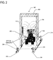
- FIG. 2 is a perspective view of a dock door and vehicle shown in the working environment
- FIG. 3A is simplified block diagram illustrating operational components of a middleware server according to an aspect of the inventory management system
- FIG. 3B illustrates a facility having a multiple dock door environment according to one aspect of the inventory management system
- FIG. 3C is a chart of an event-triggered timeslot allocation scheme according to the multiple dock door environment shown in FIG. 3B ;
- FIG. 4A is a flow chart illustrating various states of a dock door as the vehicle travels from outside of the facility to inside the facility;
- FIGS. 4B-4F are simplified block diagrams illustrating the position of the vehicle relative to the dock door for various states
- FIG. 5A is a flow chart illustrating various states of a dock door as the vehicle travels from inside of the facility to outside the facility;
- FIGS. 5B-5F are simplified block diagrams illustrating the position of the vehicle relative to the dock door for various states
- FIG. 6 a simplified block diagram illustrates a sub system for implementing a multi-client and multi-server operation over a communication network
- FIG. 7 is a flow chart illustrating a method for determining a state of the dock door and managing items of inventory.
- FIG. 1 a simplified block diagram illustrates a vehicle 102 transporting one or more items 104 of inventory 106 through a facility 108 .
- the facility 108 can be a manufacturing facility, a storage facility, or any other facility in which vehicles or any other type of mobile transportation can be used to transport items 104 to and from a staging area 109 where a plurality of items 104 (e.g., items 1 -N) are stored as inventory 106 .
- the facility 108 may include a network of RFID readers 110 that are strategically positioned at different locations throughout the facility 108 to track the location of items 104 being transported through the facility 108 .
- a first reader 112 is located at a first location, L 1 , in the facility 108 , as indicated by reference character 114
- a second reader 116 is located at a second location, L 2 , in the facility 108 , as indicated by reference character 118 .
- a RFID tag 120 can be physically affixed to or incorporated into each of the one or more items 104 of inventory 106 being transported through the facility 108 .
- the tag 120 may be affixed to items in retail inventory, warehouse inventory, manufacturing inventory, or any other type of inventory 106 .
- the first and second readers 112 , 116 may transmit first and second carrier signals 122 , 124 , respectively, which can be received by the tag 120 of an item 104 located within the transmission range of one or both of the first and second readers 112 , 116 .
- the tag 120 may be a data-carrying device that does not include an internal voltage source, and is totally passive when it is not within the transmission range of a reader. In other words, the tag 120 is only activated when it is within the transmission or read range of the first reader 112 or the second reader 116 .
- the power required to activate the tag 120 is harvested from a received carrier signal.
- the first and second carrier signals 122 , 124 may be low-voltage oscillating RF energy signals that have an initial power level P 1 .
- the tag 120 includes an energy harvesting circuit (not shown) that uses the low-voltage oscillating RF energy carrier signal to generate a voltage to power internal communication circuitry of the tag 120 .
- the tag 120 transmits data via a backscatter signal 126 having a power level P 2 , back to the first reader 112 .
- the tag 120 when the tag 120 is within the transmission range of the second reader 116 such that it receives the carrier signal 124 , the tag 120 transmits data via the backscatter signal 128 having a power level P 2 , back to the second reader 116 .
- the transmitted data contained on the backscatter signal 128 may identify the tag 120 , and/or information about the item 104 associated with the tag 120 .
- the transmission of carrier and backscatter signals between a reader and tag is known as interrogation.
- the first and second readers 112 , 116 can each be configured with communication interfaces 129 , 130 , respectively, that enable wired or wireless communication with a RFID middleware server (“middleware server”) 132 .
- the middleware server 132 can communicate with each of the first and second readers 112 , 116 for the purpose of tracking the location of items 104 being transported through the facility 108 .
- the middleware server 132 may be responsive to the type of items 104 being carried on the vehicle 102 to generate commands that can be used to control the direction the vehicle 102 may travel within the facility 108 .
- the middleware server 132 can activate and deactivate adjacent RFID readers based on the position of the vehicle 102 transporting the items 104 through the facility 108 such that frequency interference between adjacent RFID readers is avoided.
- a first sensor 134 e.g., front sensor
- second sensor 136 e.g., back sensor
- output signals 138 , 140 respectively, based on a detected position of the vehicle 102 relative to a gate 142 or access point of the facility 108 .
- a first side (e.g., front) 141 of the gate 142 leads to the outside of the facility 108 and a second side 143 (e.g., back) of the gate 142 leads to the inside of the facility 108 (e.g., shop floor).
- the middleware server 132 can be communicatively connected to the sensors 134 , 136 to receive the output signal 138 , 140 .
- the middleware server 132 is responsive to the received output signals 138 , 140 to control the operation of the first and second readers 112 , 116 such that frequency interference can be avoided.
- the middleware server 132 may activate (i.e., turn-on) the first reader 112 to collect information from the tags 120 of items 104 being transported on the vehicle 102 and may deactivate (i.e., turn-off) the second RFID reader 116 which otherwise could potentially interfere with the first reader's 112 interrogation of the tag 120 .
- the first RFID reader 112 provides information collected from the tags 120 back to the middleware server 132 .
- the middleware server 132 queries a database 144 storing inventory data 145 to identify inventory data 145 that matches the collected item information.
- the middleware 132 generates a command signal, as indicated by reference character 146 , based on the query results and transmits the generated command signal 146 to the vehicle 102 .
- the command signal 146 may include route instructions that define a particular travel route for the vehicle 102 within the facility 108 .
- the inventory management system 100 may eliminate or minimize frequency interference issues in a facility 108 having a dense network of readers 109 while still maintaining effective inventory management.
- the purpose of the middleware sever 132 is not only to gather information from the RFID readers but also from other communication devices such as infrared sensors. Additionally, the middleware server 132 may be utilized to multiplex the various communications devices and maintain a reliable wireless communication medium in this multi-sensor environment, which is prone to RF interferences and tag collisions.
- the gate 142 may be a dock door 202 and the vehicle 102 can be an automated guided vehicle (AGV), which has a mobile base that includes a microcontroller board (not show) and 900 Mhz Maxstream radio communication device (not shown).
- AGV automated guided vehicle
- two infrared sensors 206 , 208 are mounted to a leg 210 of the dock door 202
- two infrared light sources 214 , 216 are mounted to an opposite leg 218 of the dock door 202 .
- the infrared sensors 206 , 208 detect light being emitted from the infrared light sources 214 , 216 , respectively, and generate output signals (i.e., output signals 138 , 140 , respectively) that indicate the location of the vehicle 102 relative to the dock door 202 . More specifically, the magnitude of the generated output signals 138 , 140 can be used to determine whether a vehicle 102 is present at the dock door 202 and/or the state of the dock door 202 . For example, when sensors 206 , 208 detect infrared light emitted from the corresponding light sources 214 , 216 , the generated output signals 138 , 140 may each be a high voltage signal (i.e., 5 volts).
- the generated output signals may each be a low voltage signal (i.e., 0 volts).
- the magnitude of the output signals 138 , 140 of sensors 206 , 208 are described herein as being normally high, it is contemplated that in other aspects of the adaptive inventory management system the magnitude of the output signals 138 , 140 of sensors 206 , 208 can be normally low.
- the magnitude of the generated output signals 138 , 140 are described as being measured in terms of voltage, it is contemplated that the magnitude of generated output signals 138 , 140 may also be measured in terms of frequency.
- the sensors 206 , 208 may be communicatively coupled to the middleware server 132 such that the middleware server 132 can receive the generated output signals 138 , 220 .
- the middleware server 132 is responsive to the received output signal 138 , 140 to determine the state of the dock door 202 as function of the magnitude of the received output signals 138 , 140 .
- the dock door 202 can be in any one of at least six possible states: FRNT IN, FRNT OUT, BACK IN, BACK OUT, NOTHING and HOLD.
- the middleware server 132 may include decision component 302 communicatively coupled to a RFID front-end component 304 , a database front-end component 306 , a sensor front-end component 308 , and a scheduling component 310 and can issue commands to control the operation of the vehicle 102 for inventory balancing purposes as well as issue commands to control the operation of the network of RFID readers 110 within the facility 108 .
- the RFID reader front-end component 304 may be operatively coupled to the decision component 302 and provide an interface between the decision component 302 and each individual RFID reader from the network of RFID readers 110 within the facility 108 .
- the RFID reader front-end component 304 may include software, hardware, networking, and communication protocols required for communicating RFID information to the decision component 302 in a suitable format for decision-making. As described above in connection with FIG. 1 , when the tag 120 of an item being carried on a vehicle is within the reading range of a particular reader, that particular reader can interrogate the tag 120 to receive information about the item.
- the decision component 302 is responsive to tag information received from a RFID reader (e.g., readers 112 , 116 ) to issue a query request, as indicated by 312 , to the database front-end component 306 .
- a RFID reader e.g., readers 112 , 116
- the database front-end component 306 may be operatively coupled to an inventory database (e.g., database 144 ) that stores inventory data and/or vehicle data and is responsive to the query request 312 from the decision component 302 to query the database 144 to identify and retrieve inventory data that corresponds to the received tag information.
- the query results may include the location of an inventory staging area 109 for the type of item identified by the tag information.
- the decision component 302 can use the retrieved inventory staging area information to generate a command 146 to direct the vehicle 102 carrying the item 104 to that particular location within the facility 108 .
- the sensor front-end component 308 may be operatively coupled to the decision component 302 and provide an interface between the decision component 302 and sensing devices such as IR sensors 134 , 136 .
- the decision component 302 may be responsive to output information from sensors 134 , 136 to determine a position of the vehicle 102 . For example, as described above based on the magnitude of the output signals 138 , 140 , the decision component 302 can determine the position of the vehicle relative to the gate 142 .
- the decision component 302 may issue RFID commands to deactivate or activate readers based on the determined location of the vehicle 102 .
- the decision component 302 may issue a command to activate (i.e., turn-on) the first reader 112 in order to collect information from the tags 120 of items 104 being transported on the vehicle 102 and may issue a command to deactivate (i.e., turn-off) the second RFID reader 116 which otherwise could potentially interfere with the first reader's 112 interrogation of the tag 120 .
- a command to activate i.e., turn-on
- deactivate i.e., turn-off
- the timeslot scheduling component 310 employs an event-triggered timeslot allocation scheme to determine the precise timing for operating RFID readers 112 , 116 .
- the scheduling component 310 may optimally schedule operations based on certain criteria. For example, the scheduling component 310 may schedule operation of RFID readers based on the applications for which readers are being deployed. Some may be short and frequent reads (dock door) and some may be long reads but not frequent (warehouse).
- an event-triggered timeslot allocation scheme is illustrated in a multiple dock door environment (see FIG. 3B ).
- material flow can be characterized as a “jumbled” flow.
- Such flow characteristics do not allow for pre-planning and scheduling of such activities (i.e., no cyclic patterns) but rather rely on real-time events occurring in the system.
- an effective protocol for medium access is an event-triggered scheduling scheme.
- sensor 360 and sensor 362 may be used at dock doors 364 and 366 , respectively, and may be used to detect the presence of material handling equipment and then antenna 368 and antenna 370 , respectively, are powered.
- a staging area antenna 372 may operate on a time-based manner. However, if any of the dock door antennas (i.e., antenna 368 or antenna 370 ) are “powered on” then the staging area antenna will “power off” or remain “off” to avoid frequency interference.
- a data logger component 316 may be coupled to the decision component 302 and maintain a log of dock door states and all issued commands.
- An AGV commander component 318 may be coupled to the decision component 302 and can control operation of the vehicle 102 as well as monitor the position of the vehicle 102 .
- a GUI interface component 320 is coupled to the decision component 302 such that a system administrator can interact with the decision component 302 to define or view system settings, enter inventory data, and/or override the decision component 302 to control operation of the vehicle 102 .
- FIG. 4A a flow chart illustrates the various states of the dock door 202 as the vehicle 102 travels from outside of the facility 108 to inside the facility 108 .
- the first sensor 134 e.g., front sensor in FIG. 4B
- the middleware server 132 defines the state of the dock door 202 as NOTHING at step 402 .
- the middleware server 132 defines the state of the dock door 202 as NOTHING at step 402 .
- the first sensor 134 detects the vehicle 102 and produces an output signal 138 having a low magnitude (e.g., 0 volts) to indicate the vehicle 102 is present at a first side (e.g., side 141 ) of the dock door 202 .
- the second sensor 136 does not detect the vehicle 102 and is not triggered, the second sensor 136 produces an output signal 140 having a high magnitude (e.g., 5 volts) indicating the vehicle 102 is not present at the second side (e.g., side 143 ) of the dock door.
- the middleware server 132 is responsive to received output signals 138 , 140 to define the state of the dock door 202 as “FRONT IN.” After a predetermined time period expires (e.g., 3 seconds), the middleware server 132 defines the state of the dock door 202 as “HOLD” at step 406 .
- the HOLD state (see FIG. 4D ) is necessary to ensure that the vehicle 102 is located inside the dock door for a sufficient period of time to allow any RFID readers that may be located at the dock door 202 to read tags of items 104 being carried on the vehicle 102 .
- the vehicle 102 moves to a second side of the dock door 202 (see FIG.
- the vehicle 102 triggers the second sensor 136 to produce an output signal 140 having a low magnitude (e.g., 0 volts) that indicates the vehicle is present at the second side of the dock door 202 .
- the middleware server 132 is responsive to received output signals 138 , 140 to define the state of the dock door 202 as “BACK OUT.” After a specified time period (e.g., 3 seconds), the middleware server 132 defines the state of the dock door 202 as “NOTHING” at step 410 . (See FIG. 4F ).
- a flow chart illustrates the various states of the dock door 202 as the vehicle 102 travels from inside the facility 108 to outside of the facility 108 .
- the dock door 202 is idle and middleware server 132 defines the state of the dock door 202 as NOTHING at step 502 .
- the vehicle 102 triggers the second sensor 136 to produce an output signal 220 having a low magnitude (e.g., 0 volts) that indicates the vehicle 102 is present at the second side of the dock door 202 .
- the middleware server 132 may be responsive to received output signals 218 , 220 to define the state of the dock door 202 as “BACK IN.” After a specified time period (e.g., 3 seconds), the middleware server 132 can define the state of the dock door 202 as “HOLD” at step 506 . (See FIG. 5D ).
- the vehicle 102 When the vehicle 102 moves to the first side 141 of the dock door 202 (see FIG. 5E ), the vehicle 102 triggers the first sensor 134 to produce an output signal 218 having a low magnitude (e.g., 0 volts), that indicates the vehicle is present at the first side 141 of the dock door 202 .
- the middleware server 132 is responsive to received output signals 218 , 220 to define the state of the dock door 202 as “FRONT OUT.” After a specified time period (e.g., 3 seconds), the middleware server 132 defines the state of the dock door 202 as “NOTHING” at step 510 . (See FIG. 5F ).
- a simplified block diagram illustrates a sub system 600 for implementing a multi-client and multi-server operation over a communication network to allow communication between middleware server 132 and a wireless sensor device 602 .
- Each wireless sensor device 602 or vehicle 102 constitutes a node, and information from all nodes is sent to the middleware 132 through the data servers 604 .
- a router 606 can be operatively coupled to multiple middleware servers 132 and allows communication among the multiple middleware servers 132 via a communication network such as the Internet.
- the sensor front-end 308 of the middleware server 132 acts as a client that connects to the data servers for polling sensor information.
- this architecture eliminates the restrictions imposed by short-range wireless links by expanding the hierarchical networking topology to access remotely located sensors.
- the middleware 132 defines the state of the dock door as “NOTHING” at step 702 .
- the middleware server 132 queries a data log(e.g., data logger 316 ) to determine the state of the dock door 202 . If the first sensor 134 has been triggered since the last query at decision point 704 , the middleware 132 determines that the dock door 202 is in a FRONT-IN state and waits to enter the dock door 202 into a HOLD state at step 706 .
- a data log e.g., data logger 316
- the middleware server 132 waits for the first sensor 134 to indicate that the vehicle has passed the first sensor 134 (i.e., the first sensor 134 is no longer triggered) to enter the HOLD state.
- the middleware server 132 issues a command to stop the vehicle 102 , turn on the first RFID reader 112 , reads tags 120 related to items 104 being carried on the vehicle 102 , and updates an inventory database 144 based on the information retrieved from the tags 120 .
- the middleware server 132 compares information retrieved from the tags 120 with records in the inventory database 144 to determine if corresponding inventory is scheduled for receipt into inventory 106 at step 710 .
- the middleware server 132 queries a database 144 to determine if the facility 108 is scheduled to receive type X widgets into inventory 106 .
- the middleware server 132 issues a command to the vehicle 102 to proceed to a location or staging area 109 , as identified from the inventory database, for the identified items. If a match is not found, it is decided that the truck is unauthorized to deliver the order. An alert is generated and a human is asked to intervene via suitable means (e.g. via instructions on a PDA).
- the middleware 132 After a predetermined time period, the middleware 132 also verifies that the vehicle 102 exits the dock door 202 , by verifying that a BACK OUT state and NOTHING state have occurred. If the middleware cannot verify that the vehicle exited the dock door, the middleware may generate an alert message for display to a user at step 714 .
- the middleware 132 determines that the dock door 202 is in a BACK-IN state and waits to enter the dock door 202 into a HOLD state at step 716 . In other words, the middleware server 132 waits for the second sensor 136 to indicate that the vehicle has passed the second sensor 136 (i.e., the second sensor 136 is no longer triggered) to enter the HOLD state.
- the middleware server 132 issues a command to stop the vehicle 102 , turns on the first RFID reader 112 , reads tags 120 related to items 104 being carried on the vehicle 102 , and updates an inventory database 144 based on the information retrieved from the tags 120 .
- the middleware server 132 compares information retrieved from the tags 120 with records in the inventory database 144 and determines if corresponding inventory is scheduled for shipment out of inventory 106 at step 720 . For example, if a tag 120 of an item identifies the item 104 as a type Y widget, the middleware server 132 queries a database 144 to determine if type Y widgets are scheduled for shipment out of inventory 106 .
- the middleware server 132 issues a command to the vehicle 102 to proceed to a shipping location, as identified from the inventory database, for the identified items 104 . If a match is not found, it is decided that the truck is unauthorized to deliver the order. An alert is generated and a human is asked to intervene via suitable means (e.g. via instructions on a PDA). After a predetermined time period, the middleware 132 also verifies that the vehicle 102 exits the dock door 202 , by verifying that a FRONT OUT state and NOTHING state have occurred. If the middleware 132 cannot verify that the vehicle 102 exited the dock door 202 , the middleware 132 generates an alert message for display to a user at step 724 .
- suitable means e.g. via instructions on a PDA
- Embodiments of the adaptive inventory management system 100 may be implemented with computer-executable instructions.
- the computer-executable instructions may be organized into one or more computer-executable components or modules. Aspects of the invention may be implemented with any number and organization of such components or modules.
- aspects of the adaptive inventory management system 100 are not limited to the specific computer-executable instructions or the specific components or modules illustrated in the figures and described herein.
- Other embodiments of the RFID system 100 may include different computer-executable instructions or components having more or less functionality than illustrated and described herein.
Abstract
Description
Claims (23)
Priority Applications (1)
| Application Number | Priority Date | Filing Date | Title |
|---|---|---|---|
| US12/037,799 US7752089B2 (en) | 2007-03-02 | 2008-02-26 | Adaptive inventory management system |
Applications Claiming Priority (2)
| Application Number | Priority Date | Filing Date | Title |
|---|---|---|---|
| US89271107P | 2007-03-02 | 2007-03-02 | |
| US12/037,799 US7752089B2 (en) | 2007-03-02 | 2008-02-26 | Adaptive inventory management system |
Publications (2)
| Publication Number | Publication Date |
|---|---|
| US20090012882A1 US20090012882A1 (en) | 2009-01-08 |
| US7752089B2 true US7752089B2 (en) | 2010-07-06 |
Family
ID=40222210
Family Applications (1)
| Application Number | Title | Priority Date | Filing Date |
|---|---|---|---|
| US12/037,799 Expired - Fee Related US7752089B2 (en) | 2007-03-02 | 2008-02-26 | Adaptive inventory management system |
Country Status (1)
| Country | Link |
|---|---|
| US (1) | US7752089B2 (en) |
Families Citing this family (20)
| Publication number | Priority date | Publication date | Assignee | Title |
|---|---|---|---|---|
| US10262166B2 (en) | 2007-07-27 | 2019-04-16 | Lucomm Technologies, Inc. | Systems and methods for object localization and path identification based on RFID sensing |
| US9514340B2 (en) | 2007-07-27 | 2016-12-06 | Lucomm Technologies, Inc. | Systems and methods for object localization and path identification based on RFID sensing |
| US8665067B2 (en) * | 2007-07-27 | 2014-03-04 | Lucomm Technologies, Inc. | Systems and methods for object localization and path identification based on RFID sensing |
| US9720081B2 (en) | 2007-07-27 | 2017-08-01 | Lucomm Technologies, Inc. | Systems and methods for object localization and path identification based on RFID sensing |
| US20140375429A1 (en) * | 2007-07-27 | 2014-12-25 | Lucomm Technologies, Inc. | Systems and methods for object localization and path identification based on rfid sensing |
| US9513370B2 (en) | 2007-07-27 | 2016-12-06 | Lucomm Technologies, Inc. | Systems and methods for object localization and path identification based on RFID sensing |
| US7898419B2 (en) | 2007-07-27 | 2011-03-01 | Lucomm Technologies, Inc. | Systems and methods for object localization and path identification based on RFID sensing |
| US8390451B2 (en) * | 2007-10-18 | 2013-03-05 | Ianywhere Solutions, Inc. | Centralized RFID reader control and coordination |
| JP5121405B2 (en) * | 2007-11-13 | 2013-01-16 | 株式会社小松製作所 | Engine control device for construction machinery |
| DE102008046714A1 (en) * | 2008-09-11 | 2010-03-25 | Continental Automotive Gmbh | System for use in a motor vehicle and method for checking goods |
| US8326707B2 (en) * | 2009-10-08 | 2012-12-04 | At&T Intellectual Property I, Lp | Methods and systems for providing wireless enabled inventory peering |
| US9097528B2 (en) * | 2010-03-05 | 2015-08-04 | Vmware, Inc. | Managing a datacenter using mobile devices |
| GB2484458A (en) * | 2010-10-04 | 2012-04-18 | Thorn Security | Commissioning detector units of an alarm system by means of a remote infrared based communication tool |
| US20140159856A1 (en) * | 2012-12-12 | 2014-06-12 | Thorsten Meyer | Sensor hierarchy |
| TWI536311B (en) * | 2015-05-29 | 2016-06-01 | 鴻海精密工業股份有限公司 | Logistics system and logistics method |
| EP3373093B1 (en) * | 2017-03-08 | 2019-05-08 | Sick Ag | Driverless transport system |
| EP3906538A4 (en) | 2019-01-03 | 2022-10-19 | Lucomm Technologies, Inc. | Robotic devices |
| US11023695B2 (en) * | 2019-05-28 | 2021-06-01 | Airbus Canada Limited Partnership | System and method for determining a skew level |
| US10990769B1 (en) * | 2020-03-27 | 2021-04-27 | Hand Held Products, Inc. | Methods and systems for improved tag identification |
| US11752522B2 (en) * | 2020-10-23 | 2023-09-12 | United Parcel Service Of America, Inc. | Real-time tracking of parcels in a facility |
Citations (26)
| Publication number | Priority date | Publication date | Assignee | Title |
|---|---|---|---|---|
| US5525992A (en) | 1994-11-14 | 1996-06-11 | Texas Instruments Deutschland Gmbh | Method and system for conserving power in a recognition system |
| US6148291A (en) * | 1998-01-26 | 2000-11-14 | K & T Of Lorain, Ltd. | Container and inventory monitoring methods and systems |
| WO2001065481A1 (en) | 2000-03-01 | 2001-09-07 | Axcess Inc. | Radio tag system and method with tag interference avoidance |
| US6483427B1 (en) | 1996-10-17 | 2002-11-19 | Rf Technologies, Inc. | Article tracking system |
| US6600418B2 (en) * | 2000-12-12 | 2003-07-29 | 3M Innovative Properties Company | Object tracking and management system and method using radio-frequency identification tags |
| US20030174099A1 (en) | 2002-01-09 | 2003-09-18 | Westvaco Corporation | Intelligent station using multiple RF antennae and inventory control system and method incorporating same |
| US6639509B1 (en) | 1998-03-16 | 2003-10-28 | Intermec Ip Corp. | System and method for communicating with an RFID transponder with reduced noise and interference |
| US20040192247A1 (en) | 2002-07-19 | 2004-09-30 | Rotta Phillip R. | RF power control system including watchdog circuit |
| US20050080680A1 (en) | 2003-01-31 | 2005-04-14 | Kelson Elam | RFID process control system for use in automation and inventory tracking applications |
| US20050083181A1 (en) | 2003-10-16 | 2005-04-21 | Janne Jalkanen | Method, terminal and computer program product for adjusting power consumption of a RFID reader associated with a mobile terminal |
| US20050084003A1 (en) | 2003-10-21 | 2005-04-21 | Mark Duron | Full-duplex radio frequency echo cancellation |
| US20050093679A1 (en) | 2003-10-31 | 2005-05-05 | Zai Li-Cheng R. | Method and system of using active RFID tags to provide a reliable and secure RFID system |
| WO2005085899A1 (en) | 2004-03-01 | 2005-09-15 | Symbol Technologies, Inc. | Object location system and method using rfid |
| US20050280508A1 (en) | 2004-02-24 | 2005-12-22 | Jim Mravca | System and method for controlling range of successful interrogation by RFID interrogation device |
| US20060006986A1 (en) | 2004-07-09 | 2006-01-12 | Kelly Gravelle | Multi-protocol or multi-command RFID system |
| US20060012465A1 (en) | 2003-10-23 | 2006-01-19 | Nesslab Co., Ltd. | Collision prevention method for RFID system and RFID system |
| US20060022800A1 (en) | 2004-07-30 | 2006-02-02 | Reva Systems Corporation | Scheduling in an RFID system having a coordinated RFID tag reader array |
| US20060049249A1 (en) | 2004-09-09 | 2006-03-09 | Sullivan Michael S | RFID sensor array |
| US20060049946A1 (en) | 2004-09-09 | 2006-03-09 | Sullivan Michael S | RFID tag sensitivity |
| US20060054708A1 (en) | 2004-09-13 | 2006-03-16 | Samsung Electro-Mechanics Co., Ltd. | Method and apparatus for controlling power of RFID module of handheld terminal |
| US20060103535A1 (en) | 2004-11-15 | 2006-05-18 | Kourosh Pahlaven | Radio frequency tag and reader with asymmetric communication bandwidth |
| US20060176152A1 (en) | 2005-02-10 | 2006-08-10 | Psc Scanning, Inc. | RFID power ramping for tag singulation |
| US20060186999A1 (en) | 2005-02-18 | 2006-08-24 | Ctm Integration, Inc. | Apparatus and method for reading/writing to RFID tags |
| US20060197653A1 (en) | 2005-03-07 | 2006-09-07 | Compal Electronics, Inc. | Radio frequency identification monitoring system and method |
| US20060197652A1 (en) | 2005-03-04 | 2006-09-07 | International Business Machines Corporation | Method and system for proximity tracking-based adaptive power control of radio frequency identification (RFID) interrogators |
| US20060202800A1 (en) | 2003-11-25 | 2006-09-14 | Brother Kogyo Kabushiki Kaisha | RFID Tag Information Communicating Device |
-
2008
- 2008-02-26 US US12/037,799 patent/US7752089B2/en not_active Expired - Fee Related
Patent Citations (27)
| Publication number | Priority date | Publication date | Assignee | Title |
|---|---|---|---|---|
| US5525992A (en) | 1994-11-14 | 1996-06-11 | Texas Instruments Deutschland Gmbh | Method and system for conserving power in a recognition system |
| US6483427B1 (en) | 1996-10-17 | 2002-11-19 | Rf Technologies, Inc. | Article tracking system |
| US6148291A (en) * | 1998-01-26 | 2000-11-14 | K & T Of Lorain, Ltd. | Container and inventory monitoring methods and systems |
| US6639509B1 (en) | 1998-03-16 | 2003-10-28 | Intermec Ip Corp. | System and method for communicating with an RFID transponder with reduced noise and interference |
| WO2001065481A1 (en) | 2000-03-01 | 2001-09-07 | Axcess Inc. | Radio tag system and method with tag interference avoidance |
| US6600418B2 (en) * | 2000-12-12 | 2003-07-29 | 3M Innovative Properties Company | Object tracking and management system and method using radio-frequency identification tags |
| US20030174099A1 (en) | 2002-01-09 | 2003-09-18 | Westvaco Corporation | Intelligent station using multiple RF antennae and inventory control system and method incorporating same |
| US20040192247A1 (en) | 2002-07-19 | 2004-09-30 | Rotta Phillip R. | RF power control system including watchdog circuit |
| US20050080680A1 (en) | 2003-01-31 | 2005-04-14 | Kelson Elam | RFID process control system for use in automation and inventory tracking applications |
| US20050083181A1 (en) | 2003-10-16 | 2005-04-21 | Janne Jalkanen | Method, terminal and computer program product for adjusting power consumption of a RFID reader associated with a mobile terminal |
| US20050084003A1 (en) | 2003-10-21 | 2005-04-21 | Mark Duron | Full-duplex radio frequency echo cancellation |
| US20060012465A1 (en) | 2003-10-23 | 2006-01-19 | Nesslab Co., Ltd. | Collision prevention method for RFID system and RFID system |
| US20050093679A1 (en) | 2003-10-31 | 2005-05-05 | Zai Li-Cheng R. | Method and system of using active RFID tags to provide a reliable and secure RFID system |
| US20060202800A1 (en) | 2003-11-25 | 2006-09-14 | Brother Kogyo Kabushiki Kaisha | RFID Tag Information Communicating Device |
| US20050280508A1 (en) | 2004-02-24 | 2005-12-22 | Jim Mravca | System and method for controlling range of successful interrogation by RFID interrogation device |
| WO2005085899A1 (en) | 2004-03-01 | 2005-09-15 | Symbol Technologies, Inc. | Object location system and method using rfid |
| US20060006986A1 (en) | 2004-07-09 | 2006-01-12 | Kelly Gravelle | Multi-protocol or multi-command RFID system |
| US20060022800A1 (en) | 2004-07-30 | 2006-02-02 | Reva Systems Corporation | Scheduling in an RFID system having a coordinated RFID tag reader array |
| US20060022815A1 (en) | 2004-07-30 | 2006-02-02 | Fischer Jeffrey H | Interference monitoring in an RFID system |
| US20060049249A1 (en) | 2004-09-09 | 2006-03-09 | Sullivan Michael S | RFID sensor array |
| US20060049946A1 (en) | 2004-09-09 | 2006-03-09 | Sullivan Michael S | RFID tag sensitivity |
| US20060054708A1 (en) | 2004-09-13 | 2006-03-16 | Samsung Electro-Mechanics Co., Ltd. | Method and apparatus for controlling power of RFID module of handheld terminal |
| US20060103535A1 (en) | 2004-11-15 | 2006-05-18 | Kourosh Pahlaven | Radio frequency tag and reader with asymmetric communication bandwidth |
| US20060176152A1 (en) | 2005-02-10 | 2006-08-10 | Psc Scanning, Inc. | RFID power ramping for tag singulation |
| US20060186999A1 (en) | 2005-02-18 | 2006-08-24 | Ctm Integration, Inc. | Apparatus and method for reading/writing to RFID tags |
| US20060197652A1 (en) | 2005-03-04 | 2006-09-07 | International Business Machines Corporation | Method and system for proximity tracking-based adaptive power control of radio frequency identification (RFID) interrogators |
| US20060197653A1 (en) | 2005-03-07 | 2006-09-07 | Compal Electronics, Inc. | Radio frequency identification monitoring system and method |
Non-Patent Citations (5)
| Title |
|---|
| Dobkin et al., "A Radio-Oriented Introduction to RFID-Protocols, Tags and Applications," High Frequency Electronics, RFID Tutorial, Aug. 2005, pp. 32-46. |
| Dobkin et al., "The RF in RFID: A Radio-oriented Introduction to Radio Frequency Identification," Enigmatics, Jun. 7, 2005, Part II, v. 0.1, pp. 1-20. |
| IBM Corporation, "Using RFID technology to enhance output solutions," IMB Printing Systems, Mar. 2006, pp. 1-14 (16 pages). |
| Intelleflex Corporation, Passive, Battery-assisted Passive and Active Tags: A Technical Comparison, 2005, pp. 1-6. |
| Unknown, "Medium Access Mechanism to Prevent RFID Reader Collision," Inside Edge, submitted Sep. 10, 2005, pp. 1-21. |
Also Published As
| Publication number | Publication date |
|---|---|
| US20090012882A1 (en) | 2009-01-08 |
Similar Documents
| Publication | Publication Date | Title |
|---|---|---|
| US7752089B2 (en) | Adaptive inventory management system | |
| US6917291B2 (en) | Interrogation, monitoring and data exchange using RFID tags | |
| US6563417B1 (en) | Interrogation, monitoring and data exchange using RFID tags | |
| JP6957496B2 (en) | Radio node-based methods for auto-tuning the broadcast settings of nodes in a radio node network, non-temporary computer-readable media containing instructions to perform that method, and auto-tuning broadcast node equipment in a radio node network. | |
| US6662068B1 (en) | Real time total asset visibility system | |
| US7002451B2 (en) | Package location system | |
| CN1223967C (en) | Signalling system and transponder for use in system | |
| US20050246248A1 (en) | Mobile portal for radio frequency identification of objects | |
| US20060197652A1 (en) | Method and system for proximity tracking-based adaptive power control of radio frequency identification (RFID) interrogators | |
| US20070159298A1 (en) | System and method for interrogating and updating electronic shelf labels | |
| KR20060009854A (en) | Multimode wireless local area network/radio frequency identification asset tag | |
| CN103384889A (en) | RFID-based inventory monitoring systems and methods with self-adjusting operational parameters | |
| US20070159331A1 (en) | System and method for saving battery power prior to deploying an asset tag | |
| US11748706B2 (en) | Adaptive RFID inventory system | |
| WO2006107536A2 (en) | Method and system for rf activation of rf interrogators | |
| US8094022B2 (en) | Active ID tags for increased range and functionality | |
| JP2010123086A (en) | Method and device for determining propriety of ic tag reading, and computer program | |
| GB2277850A (en) | Intelligent radio frequency transponder system | |
| NL2001894C2 (en) | Locking bar for closing transport containers and system for securing and tracing transport containers with such a locking bar. | |
| CA2500112A1 (en) | Real time total asset visibility system | |
| KR101567133B1 (en) | Delivery system confirming the delay data and lose data | |
| US20230297952A1 (en) | Adaptive rfid inventory system | |
| JP2024510088A (en) | Adaptive RFID inventory system | |
| WO2023141148A1 (en) | Adaptive rfid inventory system |
Legal Events
| Date | Code | Title | Description |
|---|---|---|---|
| AS | Assignment |
Owner name: THE CURATORS OF THE UNIVERSITY OF MISSOURI, MISSOU Free format text: ASSIGNMENT OF ASSIGNORS INTEREST;ASSIGNORS:SARANGAPANI, JAGANNATHAN;RAMACHANDRAN, ANIL;SAYGIN, CAN;AND OTHERS;REEL/FRAME:020668/0193;SIGNING DATES FROM 20071210 TO 20080109 Owner name: THE CURATORS OF THE UNIVERSITY OF MISSOURI, MISSOU Free format text: ASSIGNMENT OF ASSIGNORS INTEREST;ASSIGNORS:SARANGAPANI, JAGANNATHAN;RAMACHANDRAN, ANIL;SAYGIN, CAN;AND OTHERS;SIGNING DATES FROM 20071210 TO 20080109;REEL/FRAME:020668/0193 |
|
| FEPP | Fee payment procedure |
Free format text: PATENT HOLDER CLAIMS MICRO ENTITY STATUS, ENTITY STATUS SET TO MICRO (ORIGINAL EVENT CODE: STOM); ENTITY STATUS OF PATENT OWNER: MICROENTITY |
|
| FPAY | Fee payment |
Year of fee payment: 4 |
|
| AS | Assignment |
Owner name: GOVERNMENT OF THE UNITED STATES AS REPRESENTED BY Free format text: CONFIRMATORY LICENSE;ASSIGNOR:MISSOURI UNIVERSITY OF SCIENCE AND TECHNOLOGY;REEL/FRAME:039943/0478 Effective date: 20080508 |
|
| FEPP | Fee payment procedure |
Free format text: MAINTENANCE FEE REMINDER MAILED (ORIGINAL EVENT CODE: REM.) |
|
| LAPS | Lapse for failure to pay maintenance fees |
Free format text: PATENT EXPIRED FOR FAILURE TO PAY MAINTENANCE FEES (ORIGINAL EVENT CODE: EXP.) |
|
| STCH | Information on status: patent discontinuation |
Free format text: PATENT EXPIRED DUE TO NONPAYMENT OF MAINTENANCE FEES UNDER 37 CFR 1.362 |
|
| FP | Lapsed due to failure to pay maintenance fee |
Effective date: 20180706 |