US7755026B2 - Generating signals representative of sensed light that is associated with writing being done by a user - Google Patents
Generating signals representative of sensed light that is associated with writing being done by a user Download PDFInfo
- Publication number
- US7755026B2 US7755026B2 US11/418,987 US41898706A US7755026B2 US 7755026 B2 US7755026 B2 US 7755026B2 US 41898706 A US41898706 A US 41898706A US 7755026 B2 US7755026 B2 US 7755026B2
- Authority
- US
- United States
- Prior art keywords
- array
- light
- lens
- light source
- pixel elements
- Prior art date
- Legal status (The legal status is an assumption and is not a legal conclusion. Google has not performed a legal analysis and makes no representation as to the accuracy of the status listed.)
- Expired - Fee Related
Links
Images


Classifications
-
- G—PHYSICS
- G06—COMPUTING; CALCULATING OR COUNTING
- G06F—ELECTRIC DIGITAL DATA PROCESSING
- G06F3/00—Input arrangements for transferring data to be processed into a form capable of being handled by the computer; Output arrangements for transferring data from processing unit to output unit, e.g. interface arrangements
- G06F3/01—Input arrangements or combined input and output arrangements for interaction between user and computer
- G06F3/03—Arrangements for converting the position or the displacement of a member into a coded form
- G06F3/041—Digitisers, e.g. for touch screens or touch pads, characterised by the transducing means
- G06F3/042—Digitisers, e.g. for touch screens or touch pads, characterised by the transducing means by opto-electronic means
- G06F3/0428—Digitisers, e.g. for touch screens or touch pads, characterised by the transducing means by opto-electronic means by sensing at the edges of the touch surface the interruption of optical paths, e.g. an illumination plane, parallel to the touch surface which may be virtual
-
- B—PERFORMING OPERATIONS; TRANSPORTING
- B23—MACHINE TOOLS; METAL-WORKING NOT OTHERWISE PROVIDED FOR
- B23K—SOLDERING OR UNSOLDERING; WELDING; CLADDING OR PLATING BY SOLDERING OR WELDING; CUTTING BY APPLYING HEAT LOCALLY, e.g. FLAME CUTTING; WORKING BY LASER BEAM
- B23K26/00—Working by laser beam, e.g. welding, cutting or boring
- B23K26/02—Positioning or observing the workpiece, e.g. with respect to the point of impact; Aligning, aiming or focusing the laser beam
- B23K26/04—Automatically aligning, aiming or focusing the laser beam, e.g. using the back-scattered light
- B23K26/042—Automatically aligning the laser beam
-
- B—PERFORMING OPERATIONS; TRANSPORTING
- B23—MACHINE TOOLS; METAL-WORKING NOT OTHERWISE PROVIDED FOR
- B23K—SOLDERING OR UNSOLDERING; WELDING; CLADDING OR PLATING BY SOLDERING OR WELDING; CUTTING BY APPLYING HEAT LOCALLY, e.g. FLAME CUTTING; WORKING BY LASER BEAM
- B23K26/00—Working by laser beam, e.g. welding, cutting or boring
- B23K26/70—Auxiliary operations or equipment
- B23K26/702—Auxiliary equipment
- B23K26/705—Beam measuring device
Definitions
- This disclosure relates to efficiently focusing light.
- the surface on which the pen is moving may have an array of pixels or other sensing locations, such as touch sensors, each of which responds when the pen is at such a location.
- triangulation algorithms are used to track the motion.
- the pen may emit light that is detected by sensors mounted on the writing surface, and its position may be determined based on the readings of those sensors.
- an array of sensitive pixel elements is configured to generate signals representative of sensed light that is associated with writing being done by a user, and an optical system concentrates light from a light source across a section of the array of sensitive pixel elements, the signals being useful to compute a subpixel measurement of a position of the light source.
- the array includes a row of pixels along a length of the array.
- the sensitive pixel elements are sensitive to infrared light.
- the array of sensitive pixel elements includes a lateral position measurement detector.
- the lateral position measurement detector is a CMOS linear array
- the lateral position measurement detector is a CMOS 2D array
- the lateral position measurement detector is a CCD linear array
- the lateral position measurement detector is a CCD 2D array
- the lateral position measurement detector is a position sensing detector (PSD).
- PSD position sensing detector
- the light includes infrared light.
- the optical system includes a lens.
- the lens includes a single spherical lens.
- the lens has a cross-section that is constant along a length of the lens.
- the lens includes a single cylindrical lens.
- the lens includes a single aspheric lens.
- the optical system is configured to concentrate the light into an elongated shape on the array.
- the shape is a line. Concentrating includes focusing the light onto the array.
- the optical system includes an opening in an optically opaque material.
- the optical system includes a combination of a transparent refractive lens and an opening in an optically opaque material.
- the optical system includes a series of two or more lenses
- the optical system includes a pinhole aperture
- the optical system includes a slit aperture
- the optical system includes a single Fresnel lens
- the optical system includes a series of two or more Fresnel lenses
- the optical system includes a single binary lens
- the optical system includes a series of two or more binary lenses
- the optical system includes a reflective surface positioned to reflect light from the light source onto a lens.
- the optical system includes a material to transmit infrared light and not transmit other light.
- the computed position of the light source is a vertical projection of a position of the light source onto a plane defined by the writing surface.
- a second array of sensitive pixel elements is configured to generate signals representative of the sensed light, and a second lens concentrates light from the light source across a section of the second array of sensitive pixel elements, the signals from the first and second arrays being useful to compute a subpixel measurement in two dimensions of the position of the light source.
- the first and second lens each include an opening in an optically opaque material.
- the first and second lens each include a combination of a transparent refractive lens and an opening in an optically opaque material.
- the first array and first lens together include a first sensor, and the second array and second lens together include a second sensor, in which the first and second sensors are each rotated such that the first and second arrays are not in a common plane.
- the first and second sensors are positioned such that the sensors can detect the light source as it is moved over a writing surface.
- the writing surface includes an area corresponding to a standard size of paper.
- the writing surface includes a white board.
- the writing surface includes a drawing pad.
- the first and second sensors are located about 120 mm apart and are each rotated about twelve degrees towards each other, as measured from parallel lines through the two sensors.
- the first and second sensors are located at adjacent corners of a writing surface, and each rotated forty-five degrees relative to an adjacent edge of the writing surface.
- a third and forth sensor are located at four corners of a writing surface and are each rotated forty-five degrees relative to an adjacent edge of the writing surface.
- a third and forth sensor are located along four sides of a writing surface.
- a structure is configured to hold the arrays and lenses in positions where they can detect the position of the light source as it is moved over a writing surface.
- the structure includes a pen holder.
- the structure includes a pen cap.
- the light source is associated with a writing instrument, and the pen holder is configured to accommodate the writing instrument.
- the pen holder is configured to be attached to an edge of the writing surface.
- the structure includes a body of a computer, and the writing surface includes a screen of the computer.
- an array of sensitive pixel elements is configured to generate signals representative of sensed light that is associated with writing being done by a user, the array being characterized by a plane defined by the sensitive pixel elements, an axis through the sensitive pixel elements, and a center point between equal sets of the sensitive pixel elements, and a lens concentrates light from a light source onto the array of sensitive pixel elements, the lens being characterized by an axis through its center and positioned with its axis offset from the center point of the array, the signals being useful to compute a subpixel measurement of a position of the light source.
- Implementations may include the lens being characterized by a curved surface and a flat surface, and positioned such that the flat surface is not parallel to the plane of the array.
- an array of sensitive pixel elements is configured to generate signals representative of sensed light that is associated with writing being done by a user, the array being characterized by a plane defined by the sensitive pixel elements, an axis through the sensitive pixel elements, and a center point between equal sets of the sensitive pixel elements, and a lens concentrates light from a light source onto the array of sensitive pixel elements, the lens having a curved surface and a flat surface, and positioned such that the flat surface is not parallel to the plane of the array, the signals being useful to compute a subpixel measurement of a position of the light source.
- the lens is cylindrical.
- An axis through the cylindrical shape of the lens is in a plane perpendicular to the axis of the sensitive pixel elements.
- An opening in an optically opaque material controls an amount of light reaching the lens.
- a second array of sensitive pixel elements is configured to generate signals representative of the sensed light, the second array being characterized by a plane defined by the sensitive pixel elements, an axis through the sensitive pixel elements, and a center point between equal sets of the sensitive pixel elements, and a second lens concentrates light from the light source onto the second array of sensitive pixel elements, the second lens having a curved surface and a flat surface, and positioned such that the flat surface is not parallel to the plane of the second array, the signals from the first and second arrays being useful to compute a subpixel measurement in two dimensions of the position of the light source.
- an array of sensitive pixel elements is configured to generate signals representative of sensed light that is associated with writing being done by a user
- a lens concentrates light from a light source in a shape other than a spot onto the array of sensitive pixel elements
- a reflective surface is positioned to reflect light from the light source onto the lens, when the light source is near the writing surface, the signals being useful to compute a subpixel measurement of a position of the light source.
- An optically opaque barrier may be positioned between the writing surface and the reflective surface, a portion of the barrier defining an opening positioned to admit light from the light source when the light source is near the writing surface.
- two optical sensors separated by a lateral distance are used to generate a set of signals representing subpixel values and usable to reconstruct a position of a light source that is associated with a writing instrument being used by a user, and the signals are used to compute a measurement of a position in two dimensions of the light source near a writing surface
- using the optical sensors includes using an optical system to concentrate light from the light source in a shape other than a spot onto an array of sensitive pixel elements.
- Implementations may include one or more of the following features.
- Computing the measurement includes using a quasi-triangulation algorithm.
- Computing the measurement includes using calibrated parameters.
- Computing the measurement includes using a lookup table.
- Computing the measurement includes using a polynomial approximation.
- the two optical sensors are used to generate a second set of signals representing subpixel values and usable to reconstruct a position of a second light source that is associated with a second position along a length of the writing instrument, and the first and second sets of signals are used to compute a measurement of an angle between the writing instrument and the writing surface.
- the first and second sets of signals are used to compute a position in two dimensions of a tip of the writing instrument on the writing surface.
- a device holds paper in a location, and at least two sensor assemblies are located near the location to generate signals representative of sensed light that is associated with writing being done on the paper.
- the sensor assemblies each include an array of sensitive pixel elements and a lens to concentrate light from a light source in a shape other than a spot onto the array of sensitive pixel elements.
- At least two sensor assemblies generate signals representative of sensed light that is associated with writing being done on the display.
- the sensor assemblies each include an aperture in the housing, an array of sensitive pixel elements, a lens to concentrate light from a light source in a shape other than a spot onto the array of sensitive pixel elements, and a reflective surface to direct light entering through the aperture onto the lens.
- the computer display is a monitor of a tablet computer.
- the computer display is a monitor of a laptop computer.
- the computer display is a screen of a portable communications device.
- Advantages include an improved vertical field of view to detect light reaching the sensors at an angle.
- Two light sources can be detected, allowing computation of the angle between the pen and the writing surface.
- the sensors can be positioned above or below the level of the writing surface, and at a variety of angles relative to the writing surface. Sensors can be positioned to sense writing over the entirety of a writing surface. The position of the pen can be determined with subpixel accuracy.
- a single lens can be used with each sensor to produce accurate measurements. Calibration can be performed during manufacturing.
- the sensors and/or lenses can be independently positioned to adjust the field of view and reduce blind spots.
- FIG. 1A is a perspective view of a writing instrument and sensor assembly in use.
- FIG. 1B is a schematic view of a writing instrument and sensor assembly.
- FIG. 1C is a schematic perspective view of a writing instrument.
- FIG. 1D is a geometric diagram representing a calculation of a writing instrument's position.
- FIG. 1E is a series of formulas.
- FIGS. 2 and 12A are schematic plan views of light passing through a sensor-lens assembly.
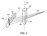
- FIG. 3 is a schematic perspective view of light passing through a sensor-lens assembly.
- FIGS. 4A-4C are schematic plan views of sensor-lens assemblies and writing surfaces.
- FIG. 4D is a schematic plan view of sensor-lens assemblies and a device screen.
- FIG. 4E is a schematic plan view of sensor-lens assemblies and a portable device with a display screen.
- FIGS. 5-7 are a schematic plan views of sensor-lens assemblies.
- FIGS. 8A-8B are perspective sectional views of sensor-lens assemblies.
- FIGS. 8C-8D are perspective views of sensor-lens assemblies.
- FIGS. 9-11 are schematic perspective views of light passing through sensor-lens assemblies.
- FIG. 12B is a perspective exploded view of a sensor-lens assembly.
- the above-referenced application describes an electronic wireless pen that emits light that is collected by external sensors to measure the pen's position with respect to the sensors.
- the pen may also be equipped with traditional writing components to leave a visible mark as it is drawn across a page.
- the sensors are CMOS or CCD linear or 2D arrays, Position Sensitive Detectors (PSD), or other light sensitive detectors.
- PSD Position Sensitive Detectors
- the sensors can be clipped to the edge of writing surface allowing reconstruction of writing on that surface.
- the position of the pen is determined by mapping the sensor readings to the actual XY position of the pen on paper.
- infrared (IR) light is used and the sensors are configured to detect IR light.
- Other light sources including ultraviolet and visible light, may be used.
- the electronic input device looks like a regular pen with a holder that contains the sensors.
- the user writes with it just as with any ordinary pen on paper, notebook or other flat surface.
- the input device is used to capture handwriting text or drawings.
- the pen's movements are detected by the sensors and communicated to the processor of the input device, which stores all of the pen's movements during its use by recording the sensor measurements into its memory.
- the input device then downloads its movements to a computer, personal digital assistant, handheld computer, cellular phone, or other device.
- the handwriting, as it appears on a page, is then automatically reconstructed from sensor information.
- the sensors' readings may be recorded by a processor positioned in the pen itself rather than directly connected to the sensors.
- the handwriting is reconstructed on the pen or pen cap/holder directly.
- a pen or other writing instrument 10 that leaves a visible trace 12 of writing or drawing in the usual way on a sheet of paper or other writing surface 14 may also have a source 16 that emits infrared (IR) light 18 for use in automatically tracking the motion of the pen.
- the light is detected by IR sensors 20 , 22 that are mounted in a pen cap 70 and held stationary relative to the pen at a nearby location, for example, near the edge 23 of the paper.
- the sensors 20 , 22 capture and deliver sequences of signals that can be interpreted by a processor (not shown) to represent the position (e.g., angle 24 between a line connecting the light source 16 and a normal vector 27 from the center of the sensor 22 ) of the pen on the writing surface 14 at which the light is received from the pen for each of a succession of measurement times.
- a processor not shown
- To calculate the actual position of the pen 10 on the writing surface 14 two angles, one from each sensor 20 , 22 , can be used in a triangulation calculation.
- Circuitry associated with the processor uses an algorithm to process the signals from the sensors 20 , 22 (and the known distance 26 between the sensors) to determine a succession of positions of the pen 10 as it is moved across the writing surface 14 .
- the algorithm can use a mathematical model that translates pixel signals of the sensors 20 , 22 into positions on the writing surface 14 .
- the algorithm could be, for example, a quasi-triangulation algorithm using calibrated parameters (e.g., distance from lens to sensor, horizontal offset between them, and others) or it could be a polynomial approximation or a lookup table, or any combination of such techniques.
- the sensors are fixed in the writing surface, for example, in a tablet PC using optical sensors rather than a digitizing surface. More than two sensors may be used, for example, four sensors, one near each corner. This may be advantageous in applications where the writing surface is large enough that there is a risk of the user inadvertently placing a hand or other object between the pen and one of the sensors.
- the particular configuration of writing surface and sensor position in a given application dictates, to at least some extent, the necessary field of view of each sensor. This in turn can be used to determine the design of the sensor, including the relationship between any lenses used and the optically sensitive elements of the sensor.
- a spherical half-ball lens is used. As shown in FIG. 2 , a spherical lens 202 focuses a ray of incident light 204 (illustrated as a slightly divergent beam) into a spot 206 on an imaginary focal plane 208 (which is actually a sphere). The position at which a sensor array 210 intercepts the refracted light is used to calculate the angle of the incident light, at the lens, in the horizontal plane of the paper.
- the refracted light actually forms a cone, tapering to a point on the focal plane, the light forms a slightly altered spot 206 a at the point it intersects the linear sensor array 210 . If this spot 206 a is larger than the height of the sensor array, or not vertically centered on it, some of the light energy in the refracted light may miss the light-sensitive elements of the sensor array 210 . In some examples, positioning the sensor array 210 and lens 202 assembly such that the vertical center of the sensor array 210 is at the same height above the writing surface 14 as the light-emitting portion 16 of the pen 10 helps assure that the spot 206 a is vertically centered on the sensor array 210 .
- This positioning also decreases errors resulting from the tilt of the pen 10 , which can cause the incident light 204 to reach the lens 202 at an angle relative to the writing surface 14 , in which case the spot 206 a is shifted vertically.
- Algorithms can be used to calculate the position of the center of the spot 206 a from whatever light is captured.
- a combination of a spherical lens with a horizontally-aligned sensor array had a vertical field of view as low as 1.5° around a horizontal line through the center of the lens 202 . This requires precise positioning of the lens relative to both the sensor array and to the writing surface.
- a cylindrical lens 302 is positioned with its curved side facing the linear sensor array 210 .
- the axis 310 of the cylinder of the lens 302 is perpendicular to the plane of the writing surface 14
- the horizontal axis 312 through the elements 314 of the linear sensor array 210 is parallel to the writing surface 14 .
- the plane of the light-sensitive elements 314 is perpendicular to that the plane of the writing surface 14 or can be slightly tilted towards it.
- Cylindrical lens 302 is a section of a cylinder having a curved face 304 and a flat face 305 .
- the cylindrical lens 302 focuses the incident light 204 into a vertical line or elongated spot 306 rather than a circular spot as with a spherical lens. Because of the orientation of the cylindrical lens 302 relative to the sensor array 210 , the vertical line 306 covers the full height of the sensor array 210 , assuring that a substantial amount of the line of light 306 reaches and effectively illuminates the light-sensitive elements 314 . Replacing a spherical lens with a cylindrical lens provides a vertical field of view of as much as 45° and allows the sensor assembly to be built with more flexible manufacturing tolerances. It also allows the sensors to detect the position of the light source 16 when it is farther away from the writing surface 14 than can be detected with a cylindrical lens.
- the cylindrical lens 302 does not enlarge the vertical dimension of the incident light 204 , and does not interfere with the ongoing divergence of the light in the vertical dimension. Rather, it focuses the horizontal spread of the incident light into a narrow range in the horizontal dimension, resulting in the line 306 that covers at least a single pixel but preferably more than one pixel, to efficiently run algorithms for finding the center of energy of the light spot with a sub-pixel resolution, that is, a resolution higher than the physical resolution of the sensor array 210 . Viewed from above, FIG. 3 would appear the same as FIG. 2 .
- One trade-off in using such a lens is a decreased overall brightness of the projected line 306 , as compared to the bright spot of a spherical lens, if such a spot could be accurately focused on the pixel elements 314 .
- the enlarged vertical field of view of a cylindrical lens also allows the use of two or more light sources, located at different positions along the length of the writing instrument, as shown in FIG. 1B .
- Two light sources 16 a and 16 b on the pen 10 project two lines 306 a , 306 b onto each of the sensor arrays 210 . This allows calculation of the angle of the pen 10 , which can be used to generate a more precise calculation of the position of its tip. The calculation can be performed using standard trigonometric calculations as shown in FIGS. 1C-1E .
- the two light sources 16 a and 16 b form line segments OA and OB, which project onto the writing surfaces as segments OA′ and OB′.
- the first light source 16 a is located a known distance a from the tip of the pen 10
- the second light source 16 b is located an additional known distance b from the first light source.
- Segments OA′ and A′B′ have corresponding lengths a′ and b′.
- the pen 10 forms an angle a with the writing surface.
- points A′ and B′ have x,y, coordinates (x 1 ,y 1 ) and (x 2 ,y 2 ), respectively, on the writing surface, as determined by processing measurements from the sensors 210 and using calibration parameters and/or lookup tables or other reconstruction techniques.
- the distances ⁇ x 12 , etc., between these points, together with the known distances a and b can be used to calculate the angle ⁇ and the coordinates (x 0 ,y 0 ) of the pen tip (point ⁇ ) using the equations in FIG. 1E .
- the distance a′ from the tip of the pen to the point A′ is given by Eq. (1).
- Cos( ⁇ ) is found from the ratio of sides OB and OB′ (Eq. (2)).
- Length b′ is found from the measured locations of points A′ and B′, from which cos 2 ( ⁇ ) is found in terms of known values (Eq. (3)).
- the distances ⁇ x 01 , ⁇ y 01 can be found based on the similarity of the triangles formed by the projected line segments and their corresponding coordinate components. That is, the ratio between distances ⁇ x 01 and ⁇ x 12 is the same as the ratio between ⁇ y 01 and ⁇ y 12 , giving the relationship in Eq. (5).
- ⁇ y 01 is found (Eq. (7a)). Again using Eq. (5), ⁇ x 01 is likewise found in terms of known quantities (Eq. (7b)).
- Tilt information may also be used for additional features, for example, allowing a user to vary the thickness of a line by varying the tilt of the pen.
- they could be configured to illuminate in an alternating pattern, with the processor synchronized to identify which is which.
- Other methods of differentiating the light sources could also be used, such as illuminating at different frequencies or flashing at different rates.
- the ability of two light sources to allow calculation of the tip position and angle may also allow the light sources to be separate from the pen itself, for example, in an attachment that can be used with any pen provided by a user.
- a “dead zone” exists outside the two sensors' respective fields of view, for example, regions 400 a, b , and c in FIG. 4A .
- the combinations 402 of sensor 210 and lens 302 are rotated slightly toward the space between the sensors. Rotating the sensor-lens combinations 402 towards the center of the page allows their fields of view to overlap to cover the page most efficiently and minimize the dead zones and optimize page coverage. This will allow also more efficient illumination of lens 302 and consequently stronger signals than if the sensors 210 were aligned with the edge 23 of the writing surface 14 . This also produces an enlarged total field of view 406 .
- the dead zone is also affected by the tilt of the pen—if the pen is close to the sensor and tilted to too great an angle, depending on the design of the light source, the light may miss the sensor assembly completely. This may be addressed by positioning the sensor farther, vertically, from the writing surface, or changing the tilt of the sensor towards or away from the writing surface.
- the larger vertical field of view of a cylindrical lens also helps address this problem.
- a single printed circuit board is used for all of the electronics including the sensors.
- the lens 302 may be rotated some amount ⁇ about its own axis 310 (measured by the original ( 502 ) and new ( 504 ) position of a normal to the flat plane of the lens 302 ), with the sensors 210 remaining parallel to the edge 23 of the writing surface 14 (see FIG. 1 ).
- the center of the lens 302 (shown by line 602 ) may be offset some distance X from the horizontal center 604 of the sensor array 210 , as shown in FIG. 6 .
- a pair of sensor-lens assemblies 402 may have their lenses 302 rotated and/or shifted by different amounts ⁇ a, ⁇ b or Xa, Xb, or in different directions, for example to allow the sensors 210 to be offset from the center of the writing surface 14 .
- lenses 302 located a distance of 4 mm away from the corresponding sensor arrays 210 (dimension Y in FIG. 7 , as measured from the axis 310 of the cylinder of the lens 302 and the sensing surface of the sensor array 210 ), with the sensor-lens assemblies 402 each rotated 12° towards the center of the writing surface and separated by 120 mm, produce a good field of view 406 covering 87% of an 8.5 ⁇ 11 inch writing surface 14 with minimal blind spots 400 a - c (extending a distance G of around 37.5 mm from the edge 23 ).
- the sensor-lens assemblies 402 in this example each have a field of view ⁇ of 131°.
- a separation distance H of only 120 mm allows the sensor-lens assemblies 402 to be conveniently located, for example, in a container for the pen, including a pen cap. It is expected that leaving the sensors 210 parallel while shifting and rotating the lenses 310 will produce the same results.
- sensors-lens assemblies 402 having only a 90° field of view ⁇ are located at two corners on one side of the writing surface 14 , a distance H of 300 mm apart. With each assembly 402 rotated 45° relative to the side of the writing surface 14 , they cover 100% of an 8.5 ⁇ 11 inch sheet with no blind spot.
- sensor-lens assemblies 402 with a 90° field of view located at all four corners of a 15 inch tablet PC monitor 410 , and rotated 45° relative to the edge of the screen, cover 100% of the screen with no blind spot.
- This may allow, for example, an optical system to be used to detect stylus input on the tablet PC rather than a digitizer or touch-screen hardware.
- a cellular telephone 412 has a screen 414 measuring 40 mm ⁇ 50 mm.
- Sensor-lens assemblies 402 with a 90° field of view ⁇ can be located at two corners of the screen 414 , separated by a distance H of 40 mm and rotated 45°, and cover 100% of the screen 414 with no blind spot.
- FIGS. 8A and 8B Two example sensor-lens assemblies 402 are shown in FIGS. 8A and 8B .
- the lens 302 is positioned near a sensor array 210 .
- the linear sensor arrays 210 are typically discreet electronic components that may be soldered or wire-bonded to a printed circuit board or to a daughter board, or they may be free-standing devices connected to other elements by wires.
- the sensor array 210 is seated in a socket 802 , which is in turn soldered to a circuit board 804 .
- the lens 302 is held in the proper position by a frame 806 .
- FIG. 806 In the example of FIG.
- the socket 802 is absent and the sensor array 210 is held in place by the same frame 806 that holds the lens 302 and connected to the circuit board 804 by wires 808 .
- the frame 806 could be attached to the circuit board 804 or could be attached to some other part, such as a housing for the entire sensor assembly (not shown).
- a spherical lens 202 as in FIG.
- details of which components can be rotated and to what extent depend on the construction of the sensor assemblies. If both sensor assemblies 402 are directly attached to a single circuit board 804 , as shown in FIG. 8C , it may be difficult to precisely position the sensors, or to position them at the desired angle. In such cases, rotating the lenses 302 within the assemblies 402 , as described with reference to FIG. 5 , may be the most practical way to assure the required field of view. If the sensor assemblies 402 include or are attached to individual circuit boards, such as daughter boards, as shown in FIG. 8D , it may be more practical to position the lenses 302 parallel to the sensors 210 within the assemblies 402 and position the individual assemblies 402 at the required angles.
- manufacturing tolerances of the frame 806 need to be such that the lens 302 and sensor array 210 can be reliably positioned within whatever tolerance is required by their sensitivity, focus, and other parameters.
- Using the frame 806 to position the sensor array 210 as shown in FIG. 8B , rather than using the circuit board 804 to position the sensor array 210 may be useful in assuring proper alignment of the lens 302 and sensor array 210 , especially in cases where the circuit board 804 is difficult to accurately position. It may also be beneficial to mount the frame 806 directly to an opening in the device where the sensors are to be used, rather than mounting the frame 806 to the printed circuit board 804 or other component part.
- tolerances in the frame of 0.025 mm have been found suitable to assure proper positioning of a linear sensor array and a spherical lens. Tolerances of 0.1 mm may be too great to allow accurate positioning of a spherical lens, but may be sufficient for a cylindrical lens.
- the sensors may be placed in-plane with the writing surface, as shown in FIG. 9 .
- mirrors 902 or other reflective surfaces may be positioned between the writing instrument and the sensor arrays 210 to direct incident light 204 onto the lens 302 and sensor array 210 .
- a barrier 904 with an opening 906 for each sensor may be used as an optical slit to position the light onto the sensor array 210 instead of or in addition to a lens.
- Infrared filters can be installed in the opening 906 to reduce the amount of ambient light reaching the sensor arrays 210 . Rather than using separate filters, in some examples, it is possible to make the lens itself from a material that will filter out ambient visible light and transmit primarily infrared light without compromising the ability of the lens to focus the light. Such materials are well known in the art.
- the angle of the mirrors 902 may be varied, allowing for the sensor arrays 210 to not be in a direct line-of-sight from the light source and through the opening 906 .
- the opening 906 could be positioned at the corner of the writing surface 14 , with the sensor array 210 positioned perpendicular to the edge 23 , and the mirror 902 positioned to direct light from the opening 906 to the lens 302 and sensor array 210 .
- This allows a 90° field of view to completely cover the entire writing surface, eliminating the blind spot 400 b in FIG. 4A .
- the mirror 902 maybe positioned to divert light 204 through opening 906 to sensor 210 positioned parallel to edge 23 of the writing surface 14 as shown in FIG. 11 .
- Various other divergences of light in three dimensions are feasible.
- adjustment screws 1202 are used to finely position the lens 302 and sensor array 210 within each assembly 402 .
- Bushings 1204 maintain tension against the force of the screws 1202 , and together with the screws hold the components in position.
- Alignment may be performed using a light source and a display (not shown) connected to the output of the sensor array 210 within the assembly 402 , for example, by placing the light source in known locations 1208 , 1210 at a distance M from the front plane of the sensor assembly 402 and a distance N to either side of the center of the sensor assembly 402 , and adjusting the screws 1202 until the appropriate signal is detected.
- the light may be provided by fixed sources integrated into an alignment tool.
- the adjustment screws 1202 may allow the sensor to be positioned both right-to-left (relative to its own center) and up and down, to assure that the sensor array is parallel to the edge of the paper (or at whatever angle is appropriate for the design).
- the specific values of M and N and the amount of adjustment necessary will depend on such factors as the tolerances of the individual assemblies and of the installation of the assemblies into the device. Screws 1212 and spacers 1214 secure the sensor assembly into a device 1206 .
- a similar process can be used to compute calibration parameters after the parts are assembled. As the pen is placed in each of a series of pre-determined locations, the response of the sensor arrays 210 is measured. These measurements are used to compute calibration parameters that can then be stored in a memory, for example, a ROM, of the device and used to adjust the measurements of the sensor arrays when the device is in use.
- a memory for example, a ROM
- the focused spot or line could have characteristics (such as being slightly out of focus or having a useful profile of intensity from one side to the other) that would be useful in connection with sensing light at the sensor array.
- a cylindrical lens need not have a constant cross-sectional shape and size along its length.
- Aspherical lenses could also be used, for example, to flatten the focal plane of the lens so that more of the sensor array is in the region where the light is tightly focused.
- Fresnel lenses may be used in place of other types of lenses, for example, to decrease the space required for the lens.
- pin holes or slits may be used in place of having any lenses at all or in addition to lenses.
- the array could be more complex and could include pixels of different sizes and shapes, multiple rows or pixels, or other patterns of pixels arranged along the length of the sensor.
- the writing surface could be a whiteboard used with markers or a drawing pad sensitive to pressure or to a magnetic stylus.
Abstract
Description
Claims (65)
Priority Applications (3)
| Application Number | Priority Date | Filing Date | Title |
|---|---|---|---|
| US11/418,987 US7755026B2 (en) | 2006-05-04 | 2006-05-04 | Generating signals representative of sensed light that is associated with writing being done by a user |
| PCT/US2007/068104 WO2007131087A2 (en) | 2006-05-04 | 2007-05-03 | Efficiently focusing light |
| EP07761792A EP2013692A2 (en) | 2006-05-04 | 2007-05-03 | Efficiently focusing light |
Applications Claiming Priority (1)
| Application Number | Priority Date | Filing Date | Title |
|---|---|---|---|
| US11/418,987 US7755026B2 (en) | 2006-05-04 | 2006-05-04 | Generating signals representative of sensed light that is associated with writing being done by a user |
Publications (2)
| Publication Number | Publication Date |
|---|---|
| US20070262246A1 US20070262246A1 (en) | 2007-11-15 |
| US7755026B2 true US7755026B2 (en) | 2010-07-13 |
Family
ID=38668544
Family Applications (1)
| Application Number | Title | Priority Date | Filing Date |
|---|---|---|---|
| US11/418,987 Expired - Fee Related US7755026B2 (en) | 2006-05-04 | 2006-05-04 | Generating signals representative of sensed light that is associated with writing being done by a user |
Country Status (3)
| Country | Link |
|---|---|
| US (1) | US7755026B2 (en) |
| EP (1) | EP2013692A2 (en) |
| WO (1) | WO2007131087A2 (en) |
Cited By (11)
| Publication number | Priority date | Publication date | Assignee | Title |
|---|---|---|---|---|
| US20100090987A1 (en) * | 2008-10-10 | 2010-04-15 | Pixart Imaging Inc. | Sensing System |
| US20100094584A1 (en) * | 2008-10-10 | 2010-04-15 | Su Tzung-Min | Sensing System and Method for Obtaining Location of Pointer thereof |
| US20100090983A1 (en) * | 2008-10-15 | 2010-04-15 | Challener David C | Techniques for Creating A Virtual Touchscreen |
| US20100094586A1 (en) * | 2008-10-10 | 2010-04-15 | Cho-Yi Lin | Sensing System |
| US20100103141A1 (en) * | 2008-10-27 | 2010-04-29 | Challener David C | Techniques for Controlling Operation of a Device with a Virtual Touchscreen |
| US20100141963A1 (en) * | 2008-10-10 | 2010-06-10 | Pixart Imaging Inc. | Sensing System and Locating Method thereof |
| US8872526B1 (en) | 2013-09-10 | 2014-10-28 | Cypress Semiconductor Corporation | Interleaving sense elements of a capacitive-sense array |
| US8903679B2 (en) | 2011-09-23 | 2014-12-02 | Cypress Semiconductor Corporation | Accuracy in a capacitive sense array |
| US20150346857A1 (en) * | 2010-02-03 | 2015-12-03 | Microsoft Technology Licensing, Llc | Combined Surface User Interface |
| US9495050B1 (en) | 2013-09-10 | 2016-11-15 | Monterey Research, Llc | Sensor pattern with signal-spreading electrodes |
| US9612265B1 (en) | 2011-09-23 | 2017-04-04 | Cypress Semiconductor Corporation | Methods and apparatus to detect a conductive object |
Families Citing this family (8)
| Publication number | Priority date | Publication date | Assignee | Title |
|---|---|---|---|---|
| US7268774B2 (en) * | 1998-08-18 | 2007-09-11 | Candledragon, Inc. | Tracking motion of a writing instrument |
| US20080018591A1 (en) * | 2006-07-20 | 2008-01-24 | Arkady Pittel | User Interfacing |
| US10180746B1 (en) | 2009-02-26 | 2019-01-15 | Amazon Technologies, Inc. | Hardware enabled interpolating sensor and display |
| US9740341B1 (en) | 2009-02-26 | 2017-08-22 | Amazon Technologies, Inc. | Capacitive sensing with interpolating force-sensitive resistor array |
| US9244562B1 (en) | 2009-07-31 | 2016-01-26 | Amazon Technologies, Inc. | Gestures and touches on force-sensitive input devices |
| JP6355081B2 (en) * | 2014-03-10 | 2018-07-11 | 任天堂株式会社 | Information processing device |
| US9578219B2 (en) * | 2014-05-14 | 2017-02-21 | Transcend Information, Inc. | Image-capturing device having infrared filtering switchover functions |
| WO2024010152A1 (en) * | 2022-07-07 | 2024-01-11 | 엘지전자 주식회사 | Display device for vehicle |
Citations (119)
| Publication number | Priority date | Publication date | Assignee | Title |
|---|---|---|---|---|
| US3376551A (en) | 1964-05-21 | 1968-04-02 | Ibm | Magnetic writing devices |
| US3559307A (en) | 1969-05-26 | 1971-02-02 | Ibm | Stylus actuated gas discharge system |
| US3581099A (en) | 1967-03-10 | 1971-05-25 | Leitz Ernst Gmbh | Toric imaging lens for slot censors for satellites |
| US3761170A (en) | 1971-02-19 | 1973-09-25 | Eastman Kodak Co | Projection lamp mounting apparatus |
| US3801741A (en) | 1971-04-30 | 1974-04-02 | Image Analysing Computers Ltd | Feature selection in image analysis |
| US3915015A (en) | 1974-03-18 | 1975-10-28 | Stanford Research Inst | Strain gauge transducer system |
| US4124838A (en) | 1976-12-29 | 1978-11-07 | Science Accessories Corporation | Apparatus for position determination |
| US4131880A (en) | 1977-10-26 | 1978-12-26 | Burroughs Corporation | Signature verification pen |
| US4550250A (en) | 1983-11-14 | 1985-10-29 | Hei, Inc. | Cordless digital graphics input device |
| US4650335A (en) | 1982-11-30 | 1987-03-17 | Asahi Kogaku Kogyo Kabushiki Kaisha | Comparison type dimension measuring method and apparatus using a laser beam in a microscope system |
| US4682016A (en) | 1984-07-20 | 1987-07-21 | Nisshin Kohki Co., Ltd. | Pen-type bar code reader |
| US4688933A (en) * | 1985-05-10 | 1987-08-25 | The Laitram Corporation | Electro-optical position determining system |
| US4705942A (en) | 1985-12-26 | 1987-11-10 | American Telephone And Telegraph Company, At&T Bell Laboratories | Pressure-sensitive light pen |
| US4710760A (en) | 1985-03-07 | 1987-12-01 | American Telephone And Telegraph Company, At&T Information Systems Inc. | Photoelastic touch-sensitive screen |
| US4751741A (en) | 1984-07-19 | 1988-06-14 | Casio Computer Co., Ltd. | Pen-type character recognition apparatus |
| US4782328A (en) | 1986-10-02 | 1988-11-01 | Product Development Services, Incorporated | Ambient-light-responsive touch screen data input method and system |
| US4806707A (en) | 1988-02-12 | 1989-02-21 | Calcomp Inc. | 3-Dimensional digitizer pen |
| US4874937A (en) | 1986-03-12 | 1989-10-17 | Kabushiki Kaisha Toshiba | Digital sun sensor |
| US4883926A (en) | 1988-04-21 | 1989-11-28 | Hewlett-Packard Company | Stylus switch |
| US4891474A (en) | 1989-02-23 | 1990-01-02 | Science Accessories Corp. | Sparking stylus for acoustic digitizer |
| US4896965A (en) | 1988-09-14 | 1990-01-30 | The United States Of America As Represented By The United States Department Of Energy | Real-time alkali monitoring system |
| US4936683A (en) | 1989-06-22 | 1990-06-26 | Summagraphics Corporation | Optical tablet construction |
| FR2650904A1 (en) | 1989-08-11 | 1991-02-15 | Aschheim Raymond | Instantaneous, automatic reader |
| US5026153A (en) | 1989-03-01 | 1991-06-25 | Mitsubishi Denki K.K. | Vehicle tracking control for continuously detecting the distance and direction to a preceding vehicle irrespective of background dark/light distribution |
| US5053757A (en) | 1987-06-04 | 1991-10-01 | Tektronix, Inc. | Touch panel with adaptive noise reduction |
| US5121441A (en) | 1990-09-21 | 1992-06-09 | International Business Machines Corporation | Robust prototype establishment in an on-line handwriting recognition system |
| US5166668A (en) | 1991-04-10 | 1992-11-24 | Data Stream Corporation | Wireless pen-type input device for use with a computer |
| US5185638A (en) | 1991-04-26 | 1993-02-09 | International Business Machines Corporation | Computer controlled, multiple angle illumination system |
| US5198877A (en) | 1990-10-15 | 1993-03-30 | Pixsys, Inc. | Method and apparatus for three-dimensional non-contact shape sensing |
| US5210405A (en) | 1990-09-05 | 1993-05-11 | Matsushita Electric Industrial Co., Ltd. | Pen-type input device for computers having ball with rotational sensors |
| US5215397A (en) | 1991-04-01 | 1993-06-01 | Yashima Electric Co., Ltd. | Writing device for storing handwriting |
| US5227622A (en) | 1992-02-06 | 1993-07-13 | Digital Stream Corp. | Wireless input system for computer using pen position detection |
| US5227732A (en) | 1991-04-30 | 1993-07-13 | Samsung Electronics Co., Ltd. | Noise reduction circuit |
| US5239139A (en) | 1990-10-12 | 1993-08-24 | Marc Zuta | Ultrasonic digitizer pen having integrated ultrasonic transmitter and receiver |
| US5247137A (en) | 1991-10-25 | 1993-09-21 | Mark Epperson | Autonomous computer input device and marking instrument |
| US5296838A (en) | 1991-04-22 | 1994-03-22 | Digital Stream Corp. | Wireless input system for computer |
| US5298737A (en) * | 1991-09-12 | 1994-03-29 | Proper R J | Measuring apparatus for determining the position of a movable element with respect to a reference |
| US5301222A (en) | 1990-01-24 | 1994-04-05 | Nec Corporation | Portable radio telephone set for generating pattern signals representative of alphanumeric letters indicative of a telephone number |
| US5308936A (en) | 1992-08-26 | 1994-05-03 | Mark S. Knighton | Ultrasonic pen-type data input device |
| US5313542A (en) | 1992-11-30 | 1994-05-17 | Breault Research Organization, Inc. | Apparatus and method of rapidly measuring hemispherical scattered or radiated light |
| US5317140A (en) | 1992-11-24 | 1994-05-31 | Dunthorn David I | Diffusion-assisted position location particularly for visual pen detection |
| US5347477A (en) | 1992-01-28 | 1994-09-13 | Jack Lee | Pen-based form computer |
| US5371516A (en) | 1989-08-18 | 1994-12-06 | Matsushita Electric Industrial Co., Ltd. | Pen-type computer input device |
| US5434371A (en) | 1994-02-01 | 1995-07-18 | A.T. Cross Company | Hand-held electronic writing tool |
| US5453762A (en) | 1993-01-20 | 1995-09-26 | Hitachi, Ltd. | Systems for processing information and identifying individual |
| US5483261A (en) | 1992-02-14 | 1996-01-09 | Itu Research, Inc. | Graphical input controller and method with rear screen image detection |
| US5517579A (en) | 1994-02-04 | 1996-05-14 | Baron R & D Ltd. | Handwritting input apparatus for handwritting recognition using more than one sensing technique |
| US5525764A (en) | 1994-06-09 | 1996-06-11 | Junkins; John L. | Laser scanning graphic input system |
| US5546538A (en) | 1993-12-14 | 1996-08-13 | Intel Corporation | System for processing handwriting written by user of portable computer by server or processing by the computer when the computer no longer communicate with server |
| US5548092A (en) | 1992-07-08 | 1996-08-20 | Shriver; Stephen A. | Apparatus and method of imaging written information |
| US5572607A (en) | 1992-09-30 | 1996-11-05 | Linotype-Hell Ag | Method and circuit arrangement for electronic retouching of images |
| US5587558A (en) | 1992-01-24 | 1996-12-24 | Seiko Instruments Inc. | Coordinate detecting apparatus having acceleration detectors |
| US5629499A (en) | 1993-11-30 | 1997-05-13 | Hewlett-Packard Company | Electronic board to store and transfer information |
| US5652412A (en) | 1994-07-11 | 1997-07-29 | Sia Technology Corp. | Pen and paper information recording system |
| US5661761A (en) | 1992-07-09 | 1997-08-26 | Fujitsu Limited | Quasi-synchronous detection and demodulation circuit and frequency discriminator used for the same |
| US5793361A (en) | 1994-06-09 | 1998-08-11 | Corporation For National Research Initiatives | Unconstrained pointing interface for natural human interaction with a display-based computer system |
| US5805719A (en) | 1994-11-28 | 1998-09-08 | Smarttouch | Tokenless identification of individuals |
| US5818424A (en) | 1995-10-19 | 1998-10-06 | International Business Machines Corporation | Rod shaped device and data acquisition apparatus for determining the position and orientation of an object in space |
| US5825921A (en) | 1993-03-19 | 1998-10-20 | Intel Corporation | Memory transfer apparatus and method useful within a pattern recognition system |
| US5831601A (en) | 1995-06-07 | 1998-11-03 | Nview Corporation | Stylus position sensing and digital camera with a digital micromirror device |
| US5874947A (en) | 1997-04-28 | 1999-02-23 | Lin; Alexis | Portable information recording/retrieving system for self service travelers |
| US5900943A (en) | 1997-08-29 | 1999-05-04 | Hewlett-Packard Company | Page identification by detection of optical characteristics |
| US5902968A (en) | 1996-02-20 | 1999-05-11 | Ricoh Company, Ltd. | Pen-shaped handwriting input apparatus using accelerometers and gyroscopes and an associated operational device for determining pen movement |
| US5945981A (en) | 1993-11-17 | 1999-08-31 | Microsoft Corporation | Wireless input device, for use with a computer, employing a movable light-emitting element and a stationary light-receiving element |
| US5963194A (en) | 1993-11-25 | 1999-10-05 | Alps Electric Co. Ltd. | Apparatus for inclination detection and input apparatus using this apparatus |
| US5996956A (en) | 1997-06-17 | 1999-12-07 | Shawver; Michael | Mounting platform for an electronic device |
| US6038333A (en) | 1998-03-16 | 2000-03-14 | Hewlett-Packard Company | Person identifier and management system |
| US6055552A (en) | 1997-10-31 | 2000-04-25 | Hewlett Packard Company | Data recording apparatus featuring spatial coordinate data merged with sequentially significant command data |
| JP2000196326A (en) | 1998-12-22 | 2000-07-14 | Nokia Mobile Phones Ltd | Manufacture of antenna body in telephone set |
| US6100538A (en) | 1997-06-13 | 2000-08-08 | Kabushikikaisha Wacom | Optical digitizer and display means for providing display of indicated position |
| US6124848A (en) | 1997-08-01 | 2000-09-26 | Lsi Logic Corporation | Method and apparatus for reducing flat panel display horizontal scan signal interference in the electrostatic pen operated digitizer |
| US6137908A (en) | 1994-06-29 | 2000-10-24 | Microsoft Corporation | Handwriting recognition system simultaneously considering shape and context information |
| US6181329B1 (en) | 1997-12-23 | 2001-01-30 | Ricoh Company, Ltd. | Method and apparatus for tracking a hand-held writing instrument with multiple sensors that are calibrated by placing the writing instrument in predetermined positions with respect to the writing surface |
| US6191778B1 (en) | 1998-05-14 | 2001-02-20 | Virtual Ink Corp. | Transcription system kit for forming composite images |
| US6236753B1 (en) | 1997-10-21 | 2001-05-22 | Sharp Kabushiki Kaisha | Apparatus and method for displaying contour lines and contour line display apparatus control program stored medium |
| US6243165B1 (en) | 1993-12-20 | 2001-06-05 | Minolta Co., Ltd. | Measuring system with improved method of reading image data of an object |
| EP0717368B1 (en) | 1994-12-16 | 2001-10-04 | Hyundai Electronics America | Digitizer stylus and method of operation |
| US20010030668A1 (en) | 2000-01-10 | 2001-10-18 | Gamze Erten | Method and system for interacting with a display |
| US6326956B1 (en) | 1998-08-24 | 2001-12-04 | Intertactile Technologies Corporation | Circuit control devices utilizing electronic display screen light |
| US6335727B1 (en) | 1993-03-12 | 2002-01-01 | Kabushiki Kaisha Toshiba | Information input device, position information holding device, and position recognizing system including them |
| US6344848B1 (en) | 1999-02-19 | 2002-02-05 | Palm, Inc. | Stylus assembly |
| US6348914B1 (en) | 1999-10-05 | 2002-02-19 | Raja S. Tuli | Writing device for storing handwriting |
| US20020031243A1 (en) | 1998-08-18 | 2002-03-14 | Ilya Schiller | Using handwritten information |
| US6377238B1 (en) | 1993-04-28 | 2002-04-23 | Mcpheters Robert Douglas | Holographic control arrangement |
| US6392821B1 (en) | 2000-09-28 | 2002-05-21 | William R. Benner, Jr. | Light display projector with wide angle capability and associated method |
| US6414673B1 (en) | 1998-11-10 | 2002-07-02 | Tidenet, Inc. | Transmitter pen location system |
| US20020118181A1 (en) | 2000-11-29 | 2002-08-29 | Oral Sekendur | Absolute optical position determination |
| US20020163511A1 (en) | 2000-11-29 | 2002-11-07 | Sekendur Oral Faith | Optical position determination on any surface |
| US6490563B2 (en) | 1998-08-17 | 2002-12-03 | Microsoft Corporation | Proofreading with text to speech feedback |
| US6501061B1 (en) | 1999-04-27 | 2002-12-31 | Gsi Lumonics Inc. | Laser calibration apparatus and method |
| US6526351B2 (en) | 2001-07-09 | 2003-02-25 | Charles Lamont Whitham | Interactive multimedia tour guide |
| US6525715B2 (en) | 1997-03-24 | 2003-02-25 | Seiko Epson Corporation | Portable information acquisition device |
| US6567078B2 (en) | 2000-01-25 | 2003-05-20 | Xiroku Inc. | Handwriting communication system and handwriting input device used therein |
| US20030095708A1 (en) | 2001-11-21 | 2003-05-22 | Arkady Pittel | Capturing hand motion |
| US6577299B1 (en) | 1998-08-18 | 2003-06-10 | Digital Ink, Inc. | Electronic portable pen apparatus and method |
| US20030122804A1 (en) | 2000-02-08 | 2003-07-03 | Osamu Yamazaki | Portable terminal |
| US20030132918A1 (en) | 2002-01-11 | 2003-07-17 | Fitch Timothy R. | Ergonomically designed multifunctional transaction terminal |
| US6614422B1 (en) | 1999-11-04 | 2003-09-02 | Canesta, Inc. | Method and apparatus for entering data using a virtual input device |
| US20030184529A1 (en) | 2002-03-29 | 2003-10-02 | Compal Electronics, Inc. | Input device for an electronic appliance |
| US6633671B2 (en) | 1998-01-28 | 2003-10-14 | California Institute Of Technology | Camera-based handwriting tracking |
| US6647145B1 (en) | 1997-01-29 | 2003-11-11 | Co-Operwrite Limited | Means for inputting characters or commands into a computer |
| EP0865192B1 (en) | 1997-03-11 | 2004-01-14 | Casio Computer Co., Ltd. | Portable terminal device for transmitting image data via network and image processing device for performing an image processing based on recognition result of received image data |
| US6760009B2 (en) * | 1998-06-09 | 2004-07-06 | Ricoh Company, Ltd. | Coordinate position inputting/detecting device, a method for inputting/detecting the coordinate position, and a display board system |
| US6811264B2 (en) | 2003-03-21 | 2004-11-02 | Mitsubishi Electric Research Laboratories, Inc. | Geometrically aware projector |
| US6856349B1 (en) | 1996-09-30 | 2005-02-15 | Intel Corporation | Method and apparatus for controlling exposure of a CMOS sensor array |
| US20050073508A1 (en) | 1998-08-18 | 2005-04-07 | Digital Ink, Inc., A Massachusetts Corporation | Tracking motion of a writing instrument |
| US6897854B2 (en) | 2001-04-12 | 2005-05-24 | Samsung Electronics Co., Ltd. | Electronic pen input device and coordinate detecting method therefor |
| US20050128184A1 (en) | 2003-12-12 | 2005-06-16 | Mcgreevy Francis T. | Virtual operating room integration |
| US20050128183A1 (en) | 2003-12-12 | 2005-06-16 | Mcgreevy Francis T. | Virtual control of electrosurgical generator functions |
| WO2005058177A1 (en) | 2003-12-12 | 2005-06-30 | Conmed Corporation | Virtual control of electrosurgical generator functions |
| US7006134B1 (en) | 1998-08-31 | 2006-02-28 | Hitachi, Ltd. | Pen type input device with camera |
| US20060077188A1 (en) | 2004-09-25 | 2006-04-13 | Samsung Electronics Co., Ltd. | Device and method for inputting characters or drawings in a mobile terminal using a virtual screen |
| US7054045B2 (en) | 2003-07-03 | 2006-05-30 | Holotouch, Inc. | Holographic human-machine interfaces |
| US7091959B1 (en) | 1999-03-31 | 2006-08-15 | Advanced Digital Systems, Inc. | System, computer program product, computing device, and associated methods for form identification and information manipulation |
| US20060290686A1 (en) | 2005-05-09 | 2006-12-28 | Sony Corporation | Input pen |
| EP0869690B1 (en) | 1997-04-03 | 2007-02-21 | Lucent Technologies Inc. | E-mail access from wireless telephones using user agents |
| US20070159453A1 (en) | 2004-01-15 | 2007-07-12 | Mikio Inoue | Mobile communication terminal |
| US20080018591A1 (en) | 2006-07-20 | 2008-01-24 | Arkady Pittel | User Interfacing |
| US20080166175A1 (en) | 2007-01-05 | 2008-07-10 | Candledragon, Inc. | Holding and Using an Electronic Pen and Paper |
-
2006
- 2006-05-04 US US11/418,987 patent/US7755026B2/en not_active Expired - Fee Related
-
2007
- 2007-05-03 WO PCT/US2007/068104 patent/WO2007131087A2/en active Application Filing
- 2007-05-03 EP EP07761792A patent/EP2013692A2/en not_active Withdrawn
Patent Citations (129)
| Publication number | Priority date | Publication date | Assignee | Title |
|---|---|---|---|---|
| US3376551A (en) | 1964-05-21 | 1968-04-02 | Ibm | Magnetic writing devices |
| US3581099A (en) | 1967-03-10 | 1971-05-25 | Leitz Ernst Gmbh | Toric imaging lens for slot censors for satellites |
| US3559307A (en) | 1969-05-26 | 1971-02-02 | Ibm | Stylus actuated gas discharge system |
| US3761170A (en) | 1971-02-19 | 1973-09-25 | Eastman Kodak Co | Projection lamp mounting apparatus |
| US3801741A (en) | 1971-04-30 | 1974-04-02 | Image Analysing Computers Ltd | Feature selection in image analysis |
| US3915015A (en) | 1974-03-18 | 1975-10-28 | Stanford Research Inst | Strain gauge transducer system |
| US4124838A (en) | 1976-12-29 | 1978-11-07 | Science Accessories Corporation | Apparatus for position determination |
| US4131880A (en) | 1977-10-26 | 1978-12-26 | Burroughs Corporation | Signature verification pen |
| US4650335A (en) | 1982-11-30 | 1987-03-17 | Asahi Kogaku Kogyo Kabushiki Kaisha | Comparison type dimension measuring method and apparatus using a laser beam in a microscope system |
| US4550250A (en) | 1983-11-14 | 1985-10-29 | Hei, Inc. | Cordless digital graphics input device |
| US4751741A (en) | 1984-07-19 | 1988-06-14 | Casio Computer Co., Ltd. | Pen-type character recognition apparatus |
| US4682016A (en) | 1984-07-20 | 1987-07-21 | Nisshin Kohki Co., Ltd. | Pen-type bar code reader |
| US4710760A (en) | 1985-03-07 | 1987-12-01 | American Telephone And Telegraph Company, At&T Information Systems Inc. | Photoelastic touch-sensitive screen |
| US4688933A (en) * | 1985-05-10 | 1987-08-25 | The Laitram Corporation | Electro-optical position determining system |
| EP0202468B1 (en) | 1985-05-10 | 1992-04-08 | The Laitram Corporation | Electro-optical position determining system |
| US4705942A (en) | 1985-12-26 | 1987-11-10 | American Telephone And Telegraph Company, At&T Bell Laboratories | Pressure-sensitive light pen |
| US4874937A (en) | 1986-03-12 | 1989-10-17 | Kabushiki Kaisha Toshiba | Digital sun sensor |
| US4782328A (en) | 1986-10-02 | 1988-11-01 | Product Development Services, Incorporated | Ambient-light-responsive touch screen data input method and system |
| US5053757A (en) | 1987-06-04 | 1991-10-01 | Tektronix, Inc. | Touch panel with adaptive noise reduction |
| US4806707A (en) | 1988-02-12 | 1989-02-21 | Calcomp Inc. | 3-Dimensional digitizer pen |
| US4883926A (en) | 1988-04-21 | 1989-11-28 | Hewlett-Packard Company | Stylus switch |
| US4896965A (en) | 1988-09-14 | 1990-01-30 | The United States Of America As Represented By The United States Department Of Energy | Real-time alkali monitoring system |
| US4891474A (en) | 1989-02-23 | 1990-01-02 | Science Accessories Corp. | Sparking stylus for acoustic digitizer |
| US5026153A (en) | 1989-03-01 | 1991-06-25 | Mitsubishi Denki K.K. | Vehicle tracking control for continuously detecting the distance and direction to a preceding vehicle irrespective of background dark/light distribution |
| US4936683A (en) | 1989-06-22 | 1990-06-26 | Summagraphics Corporation | Optical tablet construction |
| FR2650904A1 (en) | 1989-08-11 | 1991-02-15 | Aschheim Raymond | Instantaneous, automatic reader |
| US5371516A (en) | 1989-08-18 | 1994-12-06 | Matsushita Electric Industrial Co., Ltd. | Pen-type computer input device |
| US5301222A (en) | 1990-01-24 | 1994-04-05 | Nec Corporation | Portable radio telephone set for generating pattern signals representative of alphanumeric letters indicative of a telephone number |
| US5210405A (en) | 1990-09-05 | 1993-05-11 | Matsushita Electric Industrial Co., Ltd. | Pen-type input device for computers having ball with rotational sensors |
| US5121441A (en) | 1990-09-21 | 1992-06-09 | International Business Machines Corporation | Robust prototype establishment in an on-line handwriting recognition system |
| US5239139A (en) | 1990-10-12 | 1993-08-24 | Marc Zuta | Ultrasonic digitizer pen having integrated ultrasonic transmitter and receiver |
| US5198877A (en) | 1990-10-15 | 1993-03-30 | Pixsys, Inc. | Method and apparatus for three-dimensional non-contact shape sensing |
| US5215397A (en) | 1991-04-01 | 1993-06-01 | Yashima Electric Co., Ltd. | Writing device for storing handwriting |
| US5166668A (en) | 1991-04-10 | 1992-11-24 | Data Stream Corporation | Wireless pen-type input device for use with a computer |
| US5296838A (en) | 1991-04-22 | 1994-03-22 | Digital Stream Corp. | Wireless input system for computer |
| US5185638A (en) | 1991-04-26 | 1993-02-09 | International Business Machines Corporation | Computer controlled, multiple angle illumination system |
| US5227732A (en) | 1991-04-30 | 1993-07-13 | Samsung Electronics Co., Ltd. | Noise reduction circuit |
| US5298737A (en) * | 1991-09-12 | 1994-03-29 | Proper R J | Measuring apparatus for determining the position of a movable element with respect to a reference |
| US5247137A (en) | 1991-10-25 | 1993-09-21 | Mark Epperson | Autonomous computer input device and marking instrument |
| US5587558A (en) | 1992-01-24 | 1996-12-24 | Seiko Instruments Inc. | Coordinate detecting apparatus having acceleration detectors |
| US5347477A (en) | 1992-01-28 | 1994-09-13 | Jack Lee | Pen-based form computer |
| US5227622A (en) | 1992-02-06 | 1993-07-13 | Digital Stream Corp. | Wireless input system for computer using pen position detection |
| US5483261A (en) | 1992-02-14 | 1996-01-09 | Itu Research, Inc. | Graphical input controller and method with rear screen image detection |
| US5548092A (en) | 1992-07-08 | 1996-08-20 | Shriver; Stephen A. | Apparatus and method of imaging written information |
| US5661761A (en) | 1992-07-09 | 1997-08-26 | Fujitsu Limited | Quasi-synchronous detection and demodulation circuit and frequency discriminator used for the same |
| US5308936A (en) | 1992-08-26 | 1994-05-03 | Mark S. Knighton | Ultrasonic pen-type data input device |
| US5572607A (en) | 1992-09-30 | 1996-11-05 | Linotype-Hell Ag | Method and circuit arrangement for electronic retouching of images |
| US5317140A (en) | 1992-11-24 | 1994-05-31 | Dunthorn David I | Diffusion-assisted position location particularly for visual pen detection |
| US5313542A (en) | 1992-11-30 | 1994-05-17 | Breault Research Organization, Inc. | Apparatus and method of rapidly measuring hemispherical scattered or radiated light |
| US5612720A (en) | 1993-01-20 | 1997-03-18 | Hitachi Ltd. | Systems for processing information and identifying individual |
| US5453762A (en) | 1993-01-20 | 1995-09-26 | Hitachi, Ltd. | Systems for processing information and identifying individual |
| US6335727B1 (en) | 1993-03-12 | 2002-01-01 | Kabushiki Kaisha Toshiba | Information input device, position information holding device, and position recognizing system including them |
| US5825921A (en) | 1993-03-19 | 1998-10-20 | Intel Corporation | Memory transfer apparatus and method useful within a pattern recognition system |
| US6377238B1 (en) | 1993-04-28 | 2002-04-23 | Mcpheters Robert Douglas | Holographic control arrangement |
| US5945981A (en) | 1993-11-17 | 1999-08-31 | Microsoft Corporation | Wireless input device, for use with a computer, employing a movable light-emitting element and a stationary light-receiving element |
| US5963194A (en) | 1993-11-25 | 1999-10-05 | Alps Electric Co. Ltd. | Apparatus for inclination detection and input apparatus using this apparatus |
| US6014129A (en) | 1993-11-25 | 2000-01-11 | Alps Electric Co., Ltd. | Coordinate position of moving light source by using separated groups of detectors each group having an iris |
| US5629499A (en) | 1993-11-30 | 1997-05-13 | Hewlett-Packard Company | Electronic board to store and transfer information |
| US5546538A (en) | 1993-12-14 | 1996-08-13 | Intel Corporation | System for processing handwriting written by user of portable computer by server or processing by the computer when the computer no longer communicate with server |
| US6243165B1 (en) | 1993-12-20 | 2001-06-05 | Minolta Co., Ltd. | Measuring system with improved method of reading image data of an object |
| US5434371A (en) | 1994-02-01 | 1995-07-18 | A.T. Cross Company | Hand-held electronic writing tool |
| US5517579A (en) | 1994-02-04 | 1996-05-14 | Baron R & D Ltd. | Handwritting input apparatus for handwritting recognition using more than one sensing technique |
| US5793361A (en) | 1994-06-09 | 1998-08-11 | Corporation For National Research Initiatives | Unconstrained pointing interface for natural human interaction with a display-based computer system |
| US5525764A (en) | 1994-06-09 | 1996-06-11 | Junkins; John L. | Laser scanning graphic input system |
| US6137908A (en) | 1994-06-29 | 2000-10-24 | Microsoft Corporation | Handwriting recognition system simultaneously considering shape and context information |
| US5652412A (en) | 1994-07-11 | 1997-07-29 | Sia Technology Corp. | Pen and paper information recording system |
| US5805719A (en) | 1994-11-28 | 1998-09-08 | Smarttouch | Tokenless identification of individuals |
| EP0717368B1 (en) | 1994-12-16 | 2001-10-04 | Hyundai Electronics America | Digitizer stylus and method of operation |
| US5831601A (en) | 1995-06-07 | 1998-11-03 | Nview Corporation | Stylus position sensing and digital camera with a digital micromirror device |
| US5818424A (en) | 1995-10-19 | 1998-10-06 | International Business Machines Corporation | Rod shaped device and data acquisition apparatus for determining the position and orientation of an object in space |
| US5902968A (en) | 1996-02-20 | 1999-05-11 | Ricoh Company, Ltd. | Pen-shaped handwriting input apparatus using accelerometers and gyroscopes and an associated operational device for determining pen movement |
| US6856349B1 (en) | 1996-09-30 | 2005-02-15 | Intel Corporation | Method and apparatus for controlling exposure of a CMOS sensor array |
| US6647145B1 (en) | 1997-01-29 | 2003-11-11 | Co-Operwrite Limited | Means for inputting characters or commands into a computer |
| EP0865192B1 (en) | 1997-03-11 | 2004-01-14 | Casio Computer Co., Ltd. | Portable terminal device for transmitting image data via network and image processing device for performing an image processing based on recognition result of received image data |
| US6525715B2 (en) | 1997-03-24 | 2003-02-25 | Seiko Epson Corporation | Portable information acquisition device |
| EP0869690B1 (en) | 1997-04-03 | 2007-02-21 | Lucent Technologies Inc. | E-mail access from wireless telephones using user agents |
| US5874947A (en) | 1997-04-28 | 1999-02-23 | Lin; Alexis | Portable information recording/retrieving system for self service travelers |
| US6100538A (en) | 1997-06-13 | 2000-08-08 | Kabushikikaisha Wacom | Optical digitizer and display means for providing display of indicated position |
| US6441362B1 (en) | 1997-06-13 | 2002-08-27 | Kabushikikaisha Wacom | Stylus for optical digitizer |
| US5996956A (en) | 1997-06-17 | 1999-12-07 | Shawver; Michael | Mounting platform for an electronic device |
| US6124848A (en) | 1997-08-01 | 2000-09-26 | Lsi Logic Corporation | Method and apparatus for reducing flat panel display horizontal scan signal interference in the electrostatic pen operated digitizer |
| US5900943A (en) | 1997-08-29 | 1999-05-04 | Hewlett-Packard Company | Page identification by detection of optical characteristics |
| US6236753B1 (en) | 1997-10-21 | 2001-05-22 | Sharp Kabushiki Kaisha | Apparatus and method for displaying contour lines and contour line display apparatus control program stored medium |
| US6055552A (en) | 1997-10-31 | 2000-04-25 | Hewlett Packard Company | Data recording apparatus featuring spatial coordinate data merged with sequentially significant command data |
| US6181329B1 (en) | 1997-12-23 | 2001-01-30 | Ricoh Company, Ltd. | Method and apparatus for tracking a hand-held writing instrument with multiple sensors that are calibrated by placing the writing instrument in predetermined positions with respect to the writing surface |
| US6633671B2 (en) | 1998-01-28 | 2003-10-14 | California Institute Of Technology | Camera-based handwriting tracking |
| US6038333A (en) | 1998-03-16 | 2000-03-14 | Hewlett-Packard Company | Person identifier and management system |
| US6191778B1 (en) | 1998-05-14 | 2001-02-20 | Virtual Ink Corp. | Transcription system kit for forming composite images |
| US6760009B2 (en) * | 1998-06-09 | 2004-07-06 | Ricoh Company, Ltd. | Coordinate position inputting/detecting device, a method for inputting/detecting the coordinate position, and a display board system |
| US6490563B2 (en) | 1998-08-17 | 2002-12-03 | Microsoft Corporation | Proofreading with text to speech feedback |
| US20020031243A1 (en) | 1998-08-18 | 2002-03-14 | Ilya Schiller | Using handwritten information |
| US20080001078A1 (en) | 1998-08-18 | 2008-01-03 | Candledragon, Inc. | Tracking motion of a writing instrument |
| US20050073508A1 (en) | 1998-08-18 | 2005-04-07 | Digital Ink, Inc., A Massachusetts Corporation | Tracking motion of a writing instrument |
| US20070030258A1 (en) | 1998-08-18 | 2007-02-08 | Arkady Pittel | Capturing handwriting |
| US6577299B1 (en) | 1998-08-18 | 2003-06-10 | Digital Ink, Inc. | Electronic portable pen apparatus and method |
| US20060176287A1 (en) | 1998-08-18 | 2006-08-10 | Arkady Pittel | Light sources for digital pen |
| US20060176288A1 (en) | 1998-08-18 | 2006-08-10 | Arkady Pittel | Electronic pen holding |
| US6326956B1 (en) | 1998-08-24 | 2001-12-04 | Intertactile Technologies Corporation | Circuit control devices utilizing electronic display screen light |
| US7006134B1 (en) | 1998-08-31 | 2006-02-28 | Hitachi, Ltd. | Pen type input device with camera |
| US6414673B1 (en) | 1998-11-10 | 2002-07-02 | Tidenet, Inc. | Transmitter pen location system |
| JP2000196326A (en) | 1998-12-22 | 2000-07-14 | Nokia Mobile Phones Ltd | Manufacture of antenna body in telephone set |
| US6333716B1 (en) | 1998-12-22 | 2001-12-25 | Nokia Mobile Limited | Method for manufacturing an antenna body for a phone |
| US6344848B1 (en) | 1999-02-19 | 2002-02-05 | Palm, Inc. | Stylus assembly |
| US7091959B1 (en) | 1999-03-31 | 2006-08-15 | Advanced Digital Systems, Inc. | System, computer program product, computing device, and associated methods for form identification and information manipulation |
| US6501061B1 (en) | 1999-04-27 | 2002-12-31 | Gsi Lumonics Inc. | Laser calibration apparatus and method |
| US6348914B1 (en) | 1999-10-05 | 2002-02-19 | Raja S. Tuli | Writing device for storing handwriting |
| US6614422B1 (en) | 1999-11-04 | 2003-09-02 | Canesta, Inc. | Method and apparatus for entering data using a virtual input device |
| US20010030668A1 (en) | 2000-01-10 | 2001-10-18 | Gamze Erten | Method and system for interacting with a display |
| US6567078B2 (en) | 2000-01-25 | 2003-05-20 | Xiroku Inc. | Handwriting communication system and handwriting input device used therein |
| US20030122804A1 (en) | 2000-02-08 | 2003-07-03 | Osamu Yamazaki | Portable terminal |
| US6392821B1 (en) | 2000-09-28 | 2002-05-21 | William R. Benner, Jr. | Light display projector with wide angle capability and associated method |
| US20020118181A1 (en) | 2000-11-29 | 2002-08-29 | Oral Sekendur | Absolute optical position determination |
| US20020163511A1 (en) | 2000-11-29 | 2002-11-07 | Sekendur Oral Faith | Optical position determination on any surface |
| US6897854B2 (en) | 2001-04-12 | 2005-05-24 | Samsung Electronics Co., Ltd. | Electronic pen input device and coordinate detecting method therefor |
| US6526351B2 (en) | 2001-07-09 | 2003-02-25 | Charles Lamont Whitham | Interactive multimedia tour guide |
| US20030095708A1 (en) | 2001-11-21 | 2003-05-22 | Arkady Pittel | Capturing hand motion |
| US20070182725A1 (en) | 2001-11-21 | 2007-08-09 | Arkady Pittel | Capturing Hand Motion |
| US20030132918A1 (en) | 2002-01-11 | 2003-07-17 | Fitch Timothy R. | Ergonomically designed multifunctional transaction terminal |
| US20030184529A1 (en) | 2002-03-29 | 2003-10-02 | Compal Electronics, Inc. | Input device for an electronic appliance |
| US6811264B2 (en) | 2003-03-21 | 2004-11-02 | Mitsubishi Electric Research Laboratories, Inc. | Geometrically aware projector |
| US7054045B2 (en) | 2003-07-03 | 2006-05-30 | Holotouch, Inc. | Holographic human-machine interfaces |
| WO2005058177A1 (en) | 2003-12-12 | 2005-06-30 | Conmed Corporation | Virtual control of electrosurgical generator functions |
| US20050128183A1 (en) | 2003-12-12 | 2005-06-16 | Mcgreevy Francis T. | Virtual control of electrosurgical generator functions |
| US20050128184A1 (en) | 2003-12-12 | 2005-06-16 | Mcgreevy Francis T. | Virtual operating room integration |
| US20070159453A1 (en) | 2004-01-15 | 2007-07-12 | Mikio Inoue | Mobile communication terminal |
| US20060077188A1 (en) | 2004-09-25 | 2006-04-13 | Samsung Electronics Co., Ltd. | Device and method for inputting characters or drawings in a mobile terminal using a virtual screen |
| US20060290686A1 (en) | 2005-05-09 | 2006-12-28 | Sony Corporation | Input pen |
| US20080018591A1 (en) | 2006-07-20 | 2008-01-24 | Arkady Pittel | User Interfacing |
| US20080166175A1 (en) | 2007-01-05 | 2008-07-10 | Candledragon, Inc. | Holding and Using an Electronic Pen and Paper |
Non-Patent Citations (36)
| Title |
|---|
| Conant, R., et al., "A Raster-Scanning Full-Motion Video Display Using Polysilicon Micromachined Mirrors", Sensors and Actuators A: Physical, 83(1):291-296, May 2000. |
| Craft, D.J., et al., "Accelerometer Pen", IBM Technical Disclosure Bulletin, 16(12):4070, May 1974. |
| Du, H., et al., "A Virtual Keyboard Based on True-3D Optical Ranging", Proceedings of the British Machine Vision Conference, Oxford, U.K., vol. 1, pp. 220-229, Sep. 2005. |
| Hhtp://www.wowpen.us/, "Wireless Digital Pen & Mouse", printed Mar. 3, 2008. |
| International Preliminary Examination Report mailed Feb. 18, 2002 in corresponding PCT application No. PCT/US00/29758 , Publication No. WO2007/131087, published on Nov. 15, 2007 (7 pages). |
| International Preliminary Report on Patentability mailed Jan. 20, 2009 in corresponding PCT application No. PCT/US07/73576, Publication No. WO 2008/011361, published on Jan. 24, 2008 (5 pages). |
| International Preliminary Report on Patentability mailed Nov. 13, 2008 in corresponding PCT application No. PCT/US2007/068104 (10 pages). |
| International Search Report and Written Opinion mailed Aug. 1, 2008 in corresponding PCT application No. PCT/US2008/50066, Publication No. W02008/086067, published Jul. 17, 2008 (14 pages). |
| International Search Report and Written Opinion mailed Jul. 15, 2008 in corresponding PCT application No. PCT/US07/73576 (11 pages). |
| International Search Report and Written Opinion mailed Jul. 15, 2008 in corresponding PCT application No. PCT/US07/73576, Publication No. WO 2008/011361, published on Jan. 24, 2008. (11 pages). |
| International Search Report and Written Opinion mailed Oct. 1, 2008 in corresponding PCT application No. PCT/US07/68104 (13 pages). |
| International Search Report mailed Jun. 9, 2001 in corresponding PCT application No. PCT/US00/29758 (8 pages). |
| International Search Report mailed Nov. 3, 1999, in corresponding PCT application No. PCT/US99/18910, Publication No. WO 2000/11596, published on Mar. 2, 2001(2 pages). |
| International Search Report mailed Oct. 10, 2002 in corresponding PCT application No. PCT/US01/11486 (9 pages). |
| Kasabach et al., "Digital Ink: A Familiar Idea with Technological Might!", Conference on Human Factors in Computing Systems, CHI 98 conference summary on Human factors in computing systems, Los Angeles, California, United States, pp. 175-176 , Year of Publication: 1998, ISBN:1-58113-028-7. |
| Narayanaswamy, S., et al., "Using data on digital cellular and PCS voice networks", Bell Labs Technical Journal, 3(2):58-75, Apr. 1998. |
| Office action dated Aug. 15, 2008, for Chinese application No. 200710085262.2, filed on Oct. 27, 2000. |
| Office action dated Aug. 4, 2006, for Chinese application No. 00814981.X, filed on Oct. 27, 2000. |
| Office action dated Feb. 10, 2006, for Chinese application No. 00814981.X, filed on Oct. 27, 2000. |
| Office action dated Feb. 29, 2008, for Japanese application No. 2001-534078, filed on Oct. 27, 2000. |
| Office action dated Mar. 24, 2009, for Japanese application No. 566780/2000, filed on Aug. 18, 1999. |
| Office Action from Japanese Patent Office. |
| Patent 6,577,299 (U.S. Appl. No. 09/376,837), filed Aug. 18, 1999, including transaction history from PAIR (PTO website). |
| Patent 7, 257,255 (U.S. Appl. No. 09/991,539), filed Nov. 21, 2001, including transaction history from PAIR (PTO website). |
| Patent 7,268,774 (U.S. Appl. No. 10/623,284), filed Jul. 17, 2003, including transaction history from PAIR (PTO website). |
| Romano, B., "Microsoft's latest is flat-out impressive", The Seattle Times, 3 pages, Jul. 19, 2006. |
| U.S. Appl. No. 09/698,471, filed Oct. 27, 2000, including application as filed, transaction history from PAIR (PTO website). |
| U.S. Appl. No. 09/832,340, filed Apr. 10, 2001, including application as filed, transaction history from PAIR (PTO website), and pending claims. |
| U.S. Appl. No. 11/071,543, filed Apr. 2006, Byun. |
| U.S. Appl. No. 11/327,292, filed Jan. 6, 2006, including application as filed, transaction history from PAIR (PTO website), and pending claims. |
| U.S. Appl. No. 11/327,302, filed Jan. 6, 2006, including application as filed, transaction history from PAIR (PTO website), and pending claims. |
| U.S. Appl. No. 11/327,303, filed Jan. 6, 2006, including application as filed, transaction history from PAIR (PTO website), and pending claims. |
| U.S. Appl. No. 11/490,736, filed Jul. 20, 2006, including application as filed, transaction history from PAIR (PTO website), and pending claims. |
| U.S. Appl. No. 11/620,201, filed Jan. 5, 2007, including application as filed, transaction history from PAIR (PTO website), and pending claims. |
| U.S. Appl. No. 11/733,411, filed Apr. 10, 2007, including application as filed, transaction history from PAIR (PTO website), and pending claims. |
| U.S. Appl. No. 11/853,330, filed Sep. 11, 2007, including application as filed, transaction history from PAIR (PTO website), and pending claims. |
Cited By (19)
| Publication number | Priority date | Publication date | Assignee | Title |
|---|---|---|---|---|
| US8305363B2 (en) | 2008-10-10 | 2012-11-06 | Pixart Imaging | Sensing system and locating method thereof |
| US20100094584A1 (en) * | 2008-10-10 | 2010-04-15 | Su Tzung-Min | Sensing System and Method for Obtaining Location of Pointer thereof |
| US20100094586A1 (en) * | 2008-10-10 | 2010-04-15 | Cho-Yi Lin | Sensing System |
| US20100090987A1 (en) * | 2008-10-10 | 2010-04-15 | Pixart Imaging Inc. | Sensing System |
| US20100141963A1 (en) * | 2008-10-10 | 2010-06-10 | Pixart Imaging Inc. | Sensing System and Locating Method thereof |
| US8131502B2 (en) | 2008-10-10 | 2012-03-06 | Pixart Imaging Inc. | Sensing system and method for obtaining location of pointer thereof |
| US8135561B2 (en) | 2008-10-10 | 2012-03-13 | Pixart Imaging Inc. | Sensing system |
| US8232511B2 (en) * | 2008-10-10 | 2012-07-31 | Pixart Imaging Inc. | Sensing system adapted to sense a pointer and calculate a location of the pointer |
| US20100090983A1 (en) * | 2008-10-15 | 2010-04-15 | Challener David C | Techniques for Creating A Virtual Touchscreen |
| US20100103141A1 (en) * | 2008-10-27 | 2010-04-29 | Challener David C | Techniques for Controlling Operation of a Device with a Virtual Touchscreen |
| US8525776B2 (en) * | 2008-10-27 | 2013-09-03 | Lenovo (Singapore) Pte. Ltd | Techniques for controlling operation of a device with a virtual touchscreen |
| US20150346857A1 (en) * | 2010-02-03 | 2015-12-03 | Microsoft Technology Licensing, Llc | Combined Surface User Interface |
| US10452203B2 (en) * | 2010-02-03 | 2019-10-22 | Microsoft Technology Licensing, Llc | Combined surface user interface |
| US8903679B2 (en) | 2011-09-23 | 2014-12-02 | Cypress Semiconductor Corporation | Accuracy in a capacitive sense array |
| US9612265B1 (en) | 2011-09-23 | 2017-04-04 | Cypress Semiconductor Corporation | Methods and apparatus to detect a conductive object |
| US9785294B2 (en) | 2011-09-23 | 2017-10-10 | Parade Technologies, Ltd. | Accuracy in a capacitive sense array |
| US8872526B1 (en) | 2013-09-10 | 2014-10-28 | Cypress Semiconductor Corporation | Interleaving sense elements of a capacitive-sense array |
| US9495050B1 (en) | 2013-09-10 | 2016-11-15 | Monterey Research, Llc | Sensor pattern with signal-spreading electrodes |
| US9563318B2 (en) | 2013-09-10 | 2017-02-07 | Monterey Research, Llc | Interleaving conductive elements of a capacitive-sense array |
Also Published As
| Publication number | Publication date |
|---|---|
| EP2013692A2 (en) | 2009-01-14 |
| WO2007131087A3 (en) | 2008-11-27 |
| US20070262246A1 (en) | 2007-11-15 |
| WO2007131087A2 (en) | 2007-11-15 |
Similar Documents
| Publication | Publication Date | Title |
|---|---|---|
| US7755026B2 (en) | Generating signals representative of sensed light that is associated with writing being done by a user | |
| US7670006B2 (en) | System and method for projection | |
| JP3975892B2 (en) | Position measurement system | |
| US8638451B2 (en) | System for determining a location on a 2D surface or in a 3D volume | |
| US8791923B2 (en) | Touching device, laser source module, and laser source structure thereof | |
| KR101070864B1 (en) | optical touch screen | |
| JP2010257089A (en) | Optical position detection apparatus | |
| US20100110005A1 (en) | Interactive input system with multi-angle reflector | |
| TW200532571A (en) | Light emitting stylus and user input device using same | |
| US20100207909A1 (en) | Detection module and an optical detection device comprising the same | |
| JP2010277122A (en) | Optical position detection apparatus | |
| KR102328240B1 (en) | Projection of structured light for a mirror surface | |
| US7941913B2 (en) | Component placement unit as well as a component placement device comprising such a component placement unit | |
| EP1100040A2 (en) | Optical digitizer using curved mirror | |
| US8405639B1 (en) | Scanning mirror touch screen with minimum bezel height | |
| CN102591532B (en) | Dual-reflector cross-positioning electronic whiteboard device | |
| US20070241262A1 (en) | Optical sensing unit for an optical input device | |
| JP2004038528A (en) | Optical coordinate detecting device | |
| TW201627839A (en) | An optical touch device and touch detecting method using the same | |
| TW201101153A (en) | Optical detecting device, method and touch panel comprising the same | |
| JP6233941B1 (en) | Non-contact type three-dimensional touch panel, non-contact type three-dimensional touch panel system, non-contact type three-dimensional touch panel control method, program, and recording medium | |
| CN109073371B (en) | Apparatus and method for tilt detection | |
| WO2018214691A1 (en) | Optical touch sensing for displays and other applications | |
| KR20120063423A (en) | Optical touch screen | |
| US8259069B1 (en) | Speckle-based optical navigation on curved tracking surface |
Legal Events
| Date | Code | Title | Description |
|---|---|---|---|
| AS | Assignment |
Owner name: CANDLEDRAGON, INC., MASSACHUSETTS Free format text: ASSIGNMENT OF ASSIGNORS INTEREST;ASSIGNORS:PITTEL, ARKADY;GOLDMAN, ANDREW M.;ELEKTROV, STANISLAV V.;AND OTHERS;REEL/FRAME:017878/0636;SIGNING DATES FROM 20060427 TO 20060501 Owner name: CANDLEDRAGON, INC., MASSACHUSETTS Free format text: ASSIGNMENT OF ASSIGNORS INTEREST;ASSIGNORS:PITTEL, ARKADY;GOLDMAN, ANDREW M.;ELEKTROV, STANISLAV V.;AND OTHERS;SIGNING DATES FROM 20060427 TO 20060501;REEL/FRAME:017878/0636 |
|
| REMI | Maintenance fee reminder mailed | ||
| LAPS | Lapse for failure to pay maintenance fees | ||
| STCH | Information on status: patent discontinuation |
Free format text: PATENT EXPIRED DUE TO NONPAYMENT OF MAINTENANCE FEES UNDER 37 CFR 1.362 |
|
| FP | Lapsed due to failure to pay maintenance fee |
Effective date: 20140713 |