US7810322B2 - Turbo-transmission - Google Patents
Turbo-transmission Download PDFInfo
- Publication number
- US7810322B2 US7810322B2 US12/145,469 US14546908A US7810322B2 US 7810322 B2 US7810322 B2 US 7810322B2 US 14546908 A US14546908 A US 14546908A US 7810322 B2 US7810322 B2 US 7810322B2
- Authority
- US
- United States
- Prior art keywords
- turbine
- transmission
- transmission apparatus
- turbines
- gear
- Prior art date
- Legal status (The legal status is an assumption and is not a legal conclusion. Google has not performed a legal analysis and makes no representation as to the accuracy of the status listed.)
- Expired - Fee Related, expires
Links
Images


Classifications
-
- F—MECHANICAL ENGINEERING; LIGHTING; HEATING; WEAPONS; BLASTING
- F16—ENGINEERING ELEMENTS AND UNITS; GENERAL MEASURES FOR PRODUCING AND MAINTAINING EFFECTIVE FUNCTIONING OF MACHINES OR INSTALLATIONS; THERMAL INSULATION IN GENERAL
- F16H—GEARING
- F16H41/00—Rotary fluid gearing of the hydrokinetic type
- F16H41/02—Rotary fluid gearing of the hydrokinetic type with pump and turbine connected by conduits or ducts
-
- F—MECHANICAL ENGINEERING; LIGHTING; HEATING; WEAPONS; BLASTING
- F16—ENGINEERING ELEMENTS AND UNITS; GENERAL MEASURES FOR PRODUCING AND MAINTAINING EFFECTIVE FUNCTIONING OF MACHINES OR INSTALLATIONS; THERMAL INSULATION IN GENERAL
- F16D—COUPLINGS FOR TRANSMITTING ROTATION; CLUTCHES; BRAKES
- F16D33/00—Rotary fluid couplings or clutches of the hydrokinetic type
-
- F—MECHANICAL ENGINEERING; LIGHTING; HEATING; WEAPONS; BLASTING
- F16—ENGINEERING ELEMENTS AND UNITS; GENERAL MEASURES FOR PRODUCING AND MAINTAINING EFFECTIVE FUNCTIONING OF MACHINES OR INSTALLATIONS; THERMAL INSULATION IN GENERAL
- F16D—COUPLINGS FOR TRANSMITTING ROTATION; CLUTCHES; BRAKES
- F16D47/00—Systems of clutches, or clutches and couplings, comprising devices of types grouped under at least two of the preceding guide headings
- F16D47/04—Systems of clutches, or clutches and couplings, comprising devices of types grouped under at least two of the preceding guide headings of which at least one is a freewheel
-
- F—MECHANICAL ENGINEERING; LIGHTING; HEATING; WEAPONS; BLASTING
- F16—ENGINEERING ELEMENTS AND UNITS; GENERAL MEASURES FOR PRODUCING AND MAINTAINING EFFECTIVE FUNCTIONING OF MACHINES OR INSTALLATIONS; THERMAL INSULATION IN GENERAL
- F16D—COUPLINGS FOR TRANSMITTING ROTATION; CLUTCHES; BRAKES
- F16D47/00—Systems of clutches, or clutches and couplings, comprising devices of types grouped under at least two of the preceding guide headings
- F16D47/06—Systems of clutches, or clutches and couplings, comprising devices of types grouped under at least two of the preceding guide headings of which at least one is a clutch with a fluid or a semifluid as power-transmitting means
Definitions
- the present turbo transmission includes an input shaft coupled to a power source and to a pump that is configured to rotate with the input shaft.
- the hydraulic pump transfers energy received from the power source into a fluid or gas.
- the transmission includes an output shaft and a multi-stage turbine in line with each other.
- the first turbine is fixed to output shaft, the rest of the turbines are fixed on either one-way overrunning clutches or multi-disc clutches and these clutches are fixed to an output shaft and after each turbine that has multi-valves to discharge the fluid or gas.
- a planetary gear set to redirect the operation of the vehicle from forward drive (D) or to neutral (N) or to reverse drive (R).
- Turbo-transmission is hydraulic transmission and is continuously variable transmissions therefore the speed and torque will match the speed and torque is required by the vehicle therefore less energy loss.
- Modern automatic transmissions use four or more multiple-disc clutches where the clutch plate has rough frictional material on their faces. When the multiple-disc clutches are not applied the disc will run with engine or with transmission output therefore each disc acts as disc pump and will consume energy and produce heat in the transmission.
- Modern automatic transmission and manual transmissions use more than eight gears when the gears run with and without engagement with the output shaft or input shaft will act as a pump because of the teeth of the gear therefore they consume energy and produce heat in the transmission. Exemplary examples or turbo transmission units are provided herein.
- U.S. Pat. No. 2,671,543 issued Mar. 9, 1964 to J. Bosch discloses a fluid transmission system.
- the fluid transmission system uses two opposing turbines separated by a gap. Both the engine speed and the gap distance are variable to provide some additional speed variation between the motor and the driven wheels. While this patent discloses a more variable speed system the transmission has only one gear and is therefore limited in the range of speed control.
- U.S. Pat. No. 4,100,823 issued Jul. 18, 1978 discloses an automatic transmission having a hydrodynamic torque converter between the input shaft and the gear system.
- the torque converter can be disengaged from the gear system to allow for changing of the gear ratio before re-engaging the torque converter. While this patent uses a hydrodynamic torque converter, gears are still used to change the ratio turning ration of the input to output shaft.
- U.S. Pat. No. 4,624,110 issued Nov. 25, 1986 to Harry H. Levites discloses a fluid powered turbine using multiple turbines.
- the multiple turbines are configured in a tapers housing where the velocity of the fluid within the housing is increased as the fluid passes though a smaller cross sectional area thereby increasing the rotating speed of each turbine placed further down the tapered housing. While this patent describes the use of multiple turbine blades it operates as a steam turbine to generate power from steam entering the system. The generation of the pressure to turn the turbines is created external to the system as opposed to between turbines
- turbo-transmission It is an object of the turbo-transmission to create a turbo-transmission that is simpler and has fewer components than a modern automatic transmission. Only one controller is used with a few solenoid valves where the solenoids control by the transmission module (TCM) and that the transmission acts as an automatic transmission. Manual shifting can be done by operating the solenoid valves manually to act as a manual transmission or by (TCM). It is simpler in operation and less expensive than modern automatic or manual transmissions.
- turbo-transmission It is another object of the turbo-transmission to eliminate a torque converter.
- the torque converter is not required in the turbo-transmission and therefore more energy is saved from efficiency loss and weight reductions.
- turbo-transmission it is another object of the turbo-transmission to be used in all vehicles from small vehicles to large vehicles by changing the surface are of the turbine blades and or the angle of the turbine blades and or by using two or more pumps inline for heavy equipment such as trucks, tractors or bulldozers
- turbo-transmission it is still another object of the turbo-transmission to be used in other application such as pump drivers by using the motor as a power source where the turbo-transmission acts as a variable torque drive or variable speed drive for the pump and other applications.
- FIG. 1 shows a block diagram of the Turbo-Transmission connected between an engine and a vehicle.
- FIG. 2 shows a block diagram of the Turbo-Transmission connected between a motor and a pump.
- FIG. 3 Shows a system curve for a three speed Turbo-Transmission.
- FIG. 4A-4D shows a three speed Turbo-Transmission and the fluid flow through each of the three speeds.
- FIG. 5 shows a side cross sectional view of a three speed Turbo-Transmission.
- FIG. 6 shows a side cross sectional view of a five speed Turbo-Transmission.
- FIG. 7 Shows a system curve for a five speed Turbo-Transmission.
- FIG. 8 shows a front cross sectional view of one turbine of a Turbo-Transmission with the valves closed.
- FIG. 9 shows a front cross sectional view of one turbine of a Turbo-Transmission with the valves open.
- FIG. 10 shows a partial isometric view of one-way overrunning clutches or roller clutches that connect the speed turbines to the driven shaft.
- FIG. 11 shows a partial isometric view of a multiple disc clutch that connects the speed turbines to the driven shaft.
- FIG. 12 shows a side cross sectionals view of a multiple-disk clutch used in the Turbo-Transmission.
- FIG. 1 shows a block diagram of the Turbo-Transmission connected between an engine and a vehicle. From this block diagram a power source 20 such as an engine or motor is connected to the Turbo-Transmission 30 . Within the transmission is a pump 40 , fluid coupled to turbines 50 and then coupled to a gear set 60 . The Turbo-Transmission 30 is then connected to a work unit 21 such as a vehicle.
- a power source 20 such as an engine or motor
- a pump 40 Within the transmission is a pump 40 , fluid coupled to turbines 50 and then coupled to a gear set 60 .
- the Turbo-Transmission 30 is then connected to a work unit 21 such as a vehicle.
- FIG. 2 shows a block diagram of the Turbo-Transmission connected between a motor and a pump. From this block diagram a power source 20 such as an engine or motor is connected to the Turbo-Transmission 30 . Within the transmission is a pump 40 fluid coupled to turbines 50 . The Turbo-Transmission 30 is then connected to a work unit 22 such as a pump or other uses.
- a power source 20 such as an engine or motor is connected to the Turbo-Transmission 30 .
- a pump 40 fluid coupled to turbines 50 .
- the Turbo-Transmission 30 is then connected to a work unit 22 such as a pump or other uses.
- FIG. 3 Shows a system power curve for the Turbo-Transmission.
- the left vertical axis 71 is head in ft for a pump.
- the right vertical axis 73 is Torque in lb-ft for turbines on an output shaft.
- the upper horizontal axis 70 is N for the speed for a turbine in Revolutions per Minute (RPM).
- the bottom horizontal axis 72 is Q for Gallons per Minute (GPM) for a pump or turbine.
- Solid curved lines 74 represent system curves for a pump at different N, RPM(s).
- Dashed curved lines 75 represent system curves for turbines.
- the 1 st Gear curve 76 shows the first gear, Turbine 1 (T 1 )+Turbine 2 (T 2 )+Turbine 3 (T 3 ) in operation.
- the curve of 2 nd Gear 77 shows the second gear, Turbine 1 +Turbine 2 in operation.
- the curve of 3 rd Gear 78 shows the third gear, Turbine 1 in operation. The turbines and gears are described in more detail with FIGS. 4 a - 4 d.
- FIG. 4A-4D shows a three speed Turbo-Transmission and the fluid flow through turbines.
- the chart shown in FIG. 4D identifies the activation of the three solenoids to allow flow through the three turbines.
- the solenoids are designated as ON
- FIG. 4A represents a third gear where solenoid 1 is OFF and 2 and 3 are ON.
- Input shaft 26 turns pump 40 that supplies output flow 25 through turbine (T 1 ) 51 .
- solenoids 2 and 3 are ON no flow is made through turbines (T 2 ) 52 or (T 3 ) 53 .
- Roller clutches in these turbines allow the turbine to free spin on the output shaft 90 .
- FIG. 4D represents second gear where solenoid 2 is OFF and solenoids 1 and 3 are ON.
- Input shaft 26 turns pump 40 that supplies output flow 25 through turbine (T 1 ) 51 and turbine (T) 2 52 . Because solenoid 2 is OFF no flow is made through turbine or (T 3 ) 53 . Roller clutch in this turbine allow the turbine to free spin on the output shaft 90 .
- FIG. 4C represents first gear where solenoid 3 is OFF and solenoids 1 and 2 are ON.
- Input shaft 26 turns pump 40 that supplies output flow 25 through turbines (T 1 ) 51 , (T 2 ) 52 and (T 3 ) 53 that turn the output shaft 90 . Return flow 24 goes from the turbines back to the pump 40 .
- FIG. 5 shows a side cross sectional view of a three speed Turbo-Transmission.
- the turbo-transmission is essentially round and components shown on the top of this figure are also shown on the bottom of this figure.
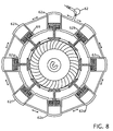
- FIGS. 8 and 9 show a cross section view of a set of three valves around the turbo-transmission and each of the three sets has eight valves it is contemplated that more or less than eight valves can be used.
- Rotational bearings 27 , 28 and 29 support the various input 26 and output 90 shafts as the power is transmitted to the input shaft 26 through the pump turbo-transmission to the output shafts 90 and 91 .
- One or more trust bearings 33 maintain the turbines in position from the thrust being exerted on them.
- input shaft 26 is turned by a motor or the like. When input shaft 26 is turned it will turn pump 40 . A portion of the flow 37 will be used to operate solenoids 81 - 83 that control valves 61 - 63 that allow one or more of the turbines 51 - 53 to turn. Valves 61 - 63 are maintained in the open position with spring(s) 69 .
- the output flow 25 from pump 40 will push against first turbine 51 and will turn the turbine on. Output flow from turbine 51 will push through the nozzle 112 to redirect flow to turbine 52 and will turn the turbine on. The flow then goes through nozzle 113 to redirect the flow to another turbine 53 and turn the turbine on and then the flow 24 will return back to the pump through nozzle 111 .
- the pressure after the pump 40 will be larger than the pressure at the nozzle 112 .
- the pressure through each successive turbine will drop gradually as the fluid flows though each turbine. Specifically the pressure at nozzle 112 will be greater than the pressure at nozzle 113 and the pressure at nozzle 113 will be larger than the pressure after turbine 53 .
- flow 37 is shown passing through only valves 82 and 83 because valve 81 is closed. Flow through the solenoids 82 and 83 then flows into valves 61 and 62 that block flow from returning 24 back to the pump. The output flow will push through nozzles 112 and 113 to turn their respective turbines.
- Turbines 52 and 53 are connected to the shaft with one-way clutches 101 and 102 the turn the shaft and also allow the turbines 52 and 53 to free spin on the shaft when flow, or insufficient flow, is not running though the turbines.
- a planetary gear set is located after the turbo-transmission on the output shaft that is connected to ring gear 31 , carrier 32 and sun gear or output shaft 91 and will be located forward of clutch 35 and reverse brake 34 and parking gear and the speed sensor.
- FIG. 6 shows a side cross sectional view of a five speed Turbo-Transmission.
- the transmission shown in this figure is similar to the transmission shown in FIG. 5 .
- the major differences are that this turbo transmission has five turbines to simulate a five speed transmission and a permanent planetary gear set overdrive 36 exists between the input shaft 26 and the pump 40 turbines.
- Output flow 25 from the pump 40 is fed to the solenoids 81 - 85 and the turbines.
- solenoid 83 is off therefore the valve 63 is open. When this valve 63 is open return flow 24 will flow back to the pump 40 .
- the remaining valves 61 , 62 , 64 and 65 will be closed and no flow will go through the opening to pump 40 .
- FIG. 7 Shows a system curve for a five speed turbo-transmission.
- the transmission shown in this figure is similar to the three speed transmission in shown and described in FIG. 3 except the speed of the pump 74 will be higher than the speed of the engine because of a permanent planetary overdrive that is located between the engine and the pump.
- FIG. 8 shows a front cross sectional view of one turbine of a Turbo-Transmission with the valves closed.
- FIG. 9 shows a front cross sectional view of one turbine of a Turbo-Transmission with the valves open. While it is shown with eight valves 62 a - 62 h existing around the turbo-transmission it is contemplated that more or less than eight valves can be used.
- the solenoid, 82 is open and flow enters all the valves 62 a - 62 h, whereby pushing the valves closed. In this orientation flow will be blocked from exiting the opening after turbine 52 (not shown).
- FIG. 8 shows a front cross sectional view of one turbine of a Turbo-Transmission with the valves closed.
- FIG. 9 shows a front cross sectional view of one turbine of a Turbo-Transmission with the valves open. While it is shown with eight valves 62 a - 62 h existing around the turbo-transmission it is contemplated that more or less than eight valves can be used
- FIG. 10 shows a partial isometric view of one-way overrunning clutches or roller clutches that connect the speed turbines to the driven shaft.
- This figure shows one contemplated embodiment of a one way clutch using a plurality or dogs or sprags 130 connected around a shaft 90 .
- the dogs or sprags 130 grip onto the shaft 90 to turn the shaft.
- the dogs or sprags release the shaft and allows the turbine to free spin on the shaft 90 .
- dogs or sprags are shown and described a number of other one-way clutches or bearing are contemplated that perform equivalently.
- FIG. 11 shows a partial isometric view of a multiple disc clutch that connects the speed turbines to the driven shaft.
- FIG. 12 shows a side cross-sectionals view of a multiple-disk clutch used in the Turbo-Transmission.
- FIG. 11 shows a shaft 90 connected to a multi-disc clutch plate 32 through bearing 131 .
- the multi-disc clutch pack 32 is shown with more detail in FIG. 12 .
- This configuration uses the pressure of the output flow 25 , which comes from the pump, to go through opening 138 to push piston 139 and lock the disk clutch 141 .
- the moving clutch plate has the turbine blades 132 that provides the rotational motion 133 on the output shaft 90 . In addition to the output flow 25 entering the opening 138 flow will also move through the nozzle(s) 140 .
- FIG. 12 shows a partial cross-sectional view of the turbine with a multiple-disc clutch connected to output shaft 90 with bearing 131 .
Abstract
Improvements in a turbo transmission are provided for transferring power from a power source to a work unit. The transmission includes an input shaft coupled to a power source and to a pump that is configured to rotate with the input shaft. The pump transfers energy received from the power source into a fluid or gas. The transmission includes an output shaft and a multi-stage turbine in line. The first turbine is fixed to output shaft, and a plurality of additional turbines are fixed on either one-way overrunning clutches or multi-disc clutches and these clutches are fixed to the output shaft and after each turbine is a multi-valves that discharges the fluid or gas. After all of the multi-stage turbines a planetary gear set connects the turbo transmission to the vehicle or work unit.
Description
Not Applicable
Not Applicable
Not Applicable
Not Applicable
1. Field of the Invention
This invention relates to improvements power transmission between a motor to a vehicle. More particularly, the present turbo transmission includes an input shaft coupled to a power source and to a pump that is configured to rotate with the input shaft. The hydraulic pump transfers energy received from the power source into a fluid or gas. The transmission includes an output shaft and a multi-stage turbine in line with each other. The first turbine is fixed to output shaft, the rest of the turbines are fixed on either one-way overrunning clutches or multi-disc clutches and these clutches are fixed to an output shaft and after each turbine that has multi-valves to discharge the fluid or gas. After the multi-stage turbines a planetary gear set to redirect the operation of the vehicle from forward drive (D) or to neutral (N) or to reverse drive (R).
2. Background of the Invention
Most automatic transmissions being used today normally have high fuel consumption because of the weight of the transmission, complicated system and does not meet economical driving conditions. Most manual transmission and automatic transmission are mechanical in nature and a portion of the time the speed and torque of the transmission does not match the speed and torque that is required by a vehicle or by other means. The transmission must match the speed of the vehicle but produces more or less torque that is required by the vehicle therefore there are some energy loss.
Turbo-transmission is hydraulic transmission and is continuously variable transmissions therefore the speed and torque will match the speed and torque is required by the vehicle therefore less energy loss.
Modern automatic transmissions use four or more multiple-disc clutches where the clutch plate has rough frictional material on their faces. When the multiple-disc clutches are not applied the disc will run with engine or with transmission output therefore each disc acts as disc pump and will consume energy and produce heat in the transmission. Modern automatic transmission and manual transmissions use more than eight gears when the gears run with and without engagement with the output shaft or input shaft will act as a pump because of the teeth of the gear therefore they consume energy and produce heat in the transmission. Exemplary examples or turbo transmission units are provided herein.
U.S. Pat. No. 2,890,600 issued Jun. 16, 1959 to R. L. Smirl et al., and U.S. Pat. No. 2,812,670 issued Nov. 12, 1957 to M. P. Winther both disclose a single stage hydraulic transmission where a viscous fluid transfers power between two vanes. These two patents disclose the early stages of a torque converter where rotational speed of the motor created connected the engine to the drive wheels. While these transmissions disclose power transmission they are limited to only a single turbo transmission speed with a multi-speed gearbox.
U.S. Pat. No. 2,671,543 issued Mar. 9, 1964 to J. Bosch discloses a fluid transmission system. The fluid transmission system uses two opposing turbines separated by a gap. Both the engine speed and the gap distance are variable to provide some additional speed variation between the motor and the driven wheels. While this patent discloses a more variable speed system the transmission has only one gear and is therefore limited in the range of speed control.
U.S. Pat. No. 4,100,823 issued Jul. 18, 1978 discloses an automatic transmission having a hydrodynamic torque converter between the input shaft and the gear system. The torque converter can be disengaged from the gear system to allow for changing of the gear ratio before re-engaging the torque converter. While this patent uses a hydrodynamic torque converter, gears are still used to change the ratio turning ration of the input to output shaft.
U.S. Pat. No. 4,624,110 issued Nov. 25, 1986 to Harry H. Levites discloses a fluid powered turbine using multiple turbines. The multiple turbines are configured in a tapers housing where the velocity of the fluid within the housing is increased as the fluid passes though a smaller cross sectional area thereby increasing the rotating speed of each turbine placed further down the tapered housing. While this patent describes the use of multiple turbine blades it operates as a steam turbine to generate power from steam entering the system. The generation of the pressure to turn the turbines is created external to the system as opposed to between turbines
What is needed is a multiple turbines that are individually controlled and connected with one-way clutches to the output shaft. The proposed application provides this solution in a simple single unit.
It is an object of the turbo-transmission to operate without frictional disc clutched or gears that create heat that results in a loss of energy.
It is an object of the turbo-transmission to create a turbo-transmission that is simpler and has fewer components than a modern automatic transmission. Only one controller is used with a few solenoid valves where the solenoids control by the transmission module (TCM) and that the transmission acts as an automatic transmission. Manual shifting can be done by operating the solenoid valves manually to act as a manual transmission or by (TCM). It is simpler in operation and less expensive than modern automatic or manual transmissions.
It is another object of the turbo-transmission to eliminate a torque converter. The torque converter is not required in the turbo-transmission and therefore more energy is saved from efficiency loss and weight reductions.
It is another object of the turbo-transmission to be used in all vehicles from small vehicles to large vehicles by changing the surface are of the turbine blades and or the angle of the turbine blades and or by using two or more pumps inline for heavy equipment such as trucks, tractors or bulldozers
It is still another object of the turbo-transmission to be used in other application such as pump drivers by using the motor as a power source where the turbo-transmission acts as a variable torque drive or variable speed drive for the pump and other applications.
Various objects, features, aspects, and advantages of the present invention will become more apparent from the following detailed description of preferred embodiments of the invention, along with the accompanying drawings in which like numerals represent like components.
or OFF and their activation or de-activation allows or prevents flow from the pump 40 through the turbines 51-53. When any solenoid valve is on (closed) no flow will exist to the solenoid valve and the valve is OFF (open) flow will be allowed to pass though the valve. FIG. 4A represents a third gear where solenoid 1 is OFF and 2 and 3 are ON. Input shaft 26 turns pump 40 that supplies output flow 25 through turbine (T1) 51. Because solenoids 2 and 3 are ON no flow is made through turbines (T2) 52 or (T3) 53. Roller clutches in these turbines allow the turbine to free spin on the output shaft 90. FIG. 4D represents second gear where solenoid 2 is OFF and solenoids 1 and 3 are ON. Input shaft 26 turns pump 40 that supplies output flow 25 through turbine (T1) 51 and turbine (T)2 52. Because solenoid 2 is OFF no flow is made through turbine or (T3) 53. Roller clutch in this turbine allow the turbine to free spin on the output shaft 90. FIG. 4C represents first gear where solenoid 3 is OFF and solenoids 1 and 2 are ON. Input shaft 26 turns pump 40 that supplies output flow 25 through turbines (T1) 51, (T2) 52 and (T3) 53 that turn the output shaft 90. Return flow 24 goes from the turbines back to the pump 40.
The output flow 25 from pump 40 will push against first turbine 51 and will turn the turbine on. Output flow from turbine 51 will push through the nozzle 112 to redirect flow to turbine 52 and will turn the turbine on. The flow then goes through nozzle 113 to redirect the flow to another turbine 53 and turn the turbine on and then the flow 24 will return back to the pump through nozzle 111. The pressure after the pump 40 will be larger than the pressure at the nozzle 112. The pressure through each successive turbine will drop gradually as the fluid flows though each turbine. Specifically the pressure at nozzle 112 will be greater than the pressure at nozzle 113 and the pressure at nozzle 113 will be larger than the pressure after turbine 53.
In this figure flow 37 is shown passing through only valves 82 and 83 because valve 81 is closed. Flow through the solenoids 82 and 83 then flows into valves 61 and 62 that block flow from returning 24 back to the pump. The output flow will push through nozzles 112 and 113 to turn their respective turbines. Turbines 52 and 53 are connected to the shaft with one- way clutches 101 and 102 the turn the shaft and also allow the turbines 52 and 53 to free spin on the shaft when flow, or insufficient flow, is not running though the turbines. A planetary gear set is located after the turbo-transmission on the output shaft that is connected to ring gear 31, carrier 32 and sun gear or output shaft 91 and will be located forward of clutch 35 and reverse brake 34 and parking gear and the speed sensor.
Thus, specific embodiments of a hydrodynamic turbo-transmission have been disclosed. It should be apparent, however, to those skilled in the art that many more modifications besides those described are possible without departing from the inventive concepts herein. The inventive subject matter, therefore, is not to be restricted except in the spirit of the appended claims.
Claims (18)
1. A transmission apparatus configured to transmit energy from a power source to work unite the transmission apparatus comprising:
an outer housing defining an interior region containing a fluid;
an input shaft being coupled to a power source to receive energy there from;
said input shaft being couple to a pump to transfer energy from said power source into the fluid and then to a multi-stage turbine;
a first turbine positioned in front of said pump and is fixed to an output shaft;
at least a second turbine located in series after said first turbine rotationally secured to said output shaft with a one-way overrunning clutch or multiple-disc clutch;
a plurality of valves located after each turbine that are opened to discharge fluid or gas after each turbine or closed to allow flow to said second or subsequent turbine(s) wherein;
said one-way overrunning clutch or said multiple-disc clutch will be locked in the same direction of said first turbine and will be free to rotate in an opposing direction without appreciable drag on said output shaft, and
said turbines will transfer power when the differential pressure before and after said turbines is sufficient to turn said turbines and lock said one-way overrunning clutch or multi-disc clutch and to transfer power to said output shaft.
2. The transmission apparatus according to claim 1 wherein said plurality of valves are opened or closed under control of corresponding solenoids to change a drive ratio between the input and output shaft.
3. The transmission apparatus according to claim 2 wherein a nozzle is located between said first and second turbines to redirect the fluid or gas to said second turbine or to any open valves.
4. The transmission apparatus according to claim 2 wherein all said turbines before said open valves will be in driven rotation and any turbine after the last open set of said valves will be in free rotation on said output shaft because no fluid is flowing through any remaining turbine.
5. The transmission apparatus according to claim 2 wherein all of said solenoids are operable manually to act as a manual transmission or by a transmission control module that acts as an automatic transmission.
6. The transmission apparatus according to claim 2 wherein all said valves operate by pressurized fluid that is created by said pump through said solenoid.
7. The transmission apparatus according to claim 1 wherein each said turbine has a different blade size and or angle to create a different gear ratio.
8. The transmission apparatus according to claim 1 that further includes a planetary gear set, sun gear, carrier, ring gear that provides reverse, neutral, and forward operations.
9. The transmission apparatus according to claim 1 wherein said transmission uses two separate controllers where one controller controls the turbine operation and a second controller controls the vehicle operation for reverse, neutral and forward.
10. The transmission apparatus according to claim 1 wherein the number of turbines in said transmission will correspond to the number of gears in the transmission.
11. The transmission apparatus according to claim 10 wherein the number of turbines is five and there are five of said valves, each having a solenoid.
12. The transmission apparatus according to claim 11 wherein operation of said first turbine corresponds to a fifth gear or overdrive gear.
13. The transmission apparatus according to claim 11 wherein operation of said first and second turbine corresponds to a fourth gear.
14. The transmission apparatus according to claim 11 wherein operation of said first and second turbines, and a third turbine corresponds to a third gear.
15. The transmission apparatus according to claim 11 wherein operation of said first and second turbines, and a third and fourth turbine corresponds to a second gear.
16. The transmission apparatus according to claim 11 wherein operation of said first and second turbines, and a third, fourth and fifth turbine corresponds to a first gear.
17. The transmission apparatus according to claim 1 wherein said one-way clutch or said multiple disc clutch is said one-way overrunning clutch whereby said second turbine transfers power when differential pressure before and after said second turbine is sufficient to run said one-way overrunning clutch into engagement with said output shaft.
18. The transmission apparatus according to claim 1 wherein said one-way clutch or said multiple disc clutch is said multi-disc clutch whereby said second turbine transfers power when differential pressure before and after said second turbine is sufficient to run said multi-disc clutch into engagement with said output shaft.
Priority Applications (13)
| Application Number | Priority Date | Filing Date | Title |
|---|---|---|---|
| US12/145,469 US7810322B2 (en) | 2008-06-24 | 2008-06-24 | Turbo-transmission |
| PCT/US2008/008139 WO2009157909A1 (en) | 2008-06-24 | 2008-06-30 | Turbo-transmission |
| PCT/US2009/040060 WO2009158059A1 (en) | 2008-06-24 | 2009-04-09 | Hydraulic hybrid turbo-transmission |
| EP09770594A EP2288799A1 (en) | 2008-06-24 | 2009-04-09 | Hydraulic hybrid turbo-transmission |
| US12/421,286 US20090313984A1 (en) | 2008-06-24 | 2009-04-09 | Hydraulic hybrid turbo transmission |
| CA2727050A CA2727050A1 (en) | 2008-06-24 | 2009-04-09 | Hydraulic hybrid turbo-transmission |
| JP2011514641A JP2011525598A (en) | 2008-06-24 | 2009-04-09 | Hydraulic hybrid turbo transmission |
| EP09770718A EP2288824A1 (en) | 2008-06-24 | 2009-06-09 | Pneumatic hybrid turbo-transmission |
| US12/481,159 US8235150B2 (en) | 2008-06-24 | 2009-06-09 | Pneumatic hybrid turbo transmission |
| JP2011514700A JP2011525580A (en) | 2008-06-24 | 2009-06-09 | Pneumatic hybrid turbo transmission |
| CA2727060A CA2727060A1 (en) | 2008-06-24 | 2009-06-09 | Pneumatic hybrid turbo transmission |
| PCT/US2009/046745 WO2009158184A1 (en) | 2008-06-24 | 2009-06-09 | Pneumatic hybrid turbo-transmission |
| US12/623,879 US8336304B2 (en) | 2008-06-24 | 2009-11-23 | Hydraulic hybrid turbo-transmission |
Applications Claiming Priority (1)
| Application Number | Priority Date | Filing Date | Title |
|---|---|---|---|
| US12/145,469 US7810322B2 (en) | 2008-06-24 | 2008-06-24 | Turbo-transmission |
Related Parent Applications (1)
| Application Number | Title | Priority Date | Filing Date |
|---|---|---|---|
| US12/269,261 Continuation-In-Part US8087487B2 (en) | 2008-06-24 | 2008-11-12 | Hybrid turbo transmission |
Related Child Applications (3)
| Application Number | Title | Priority Date | Filing Date |
|---|---|---|---|
| US12/421,286 Continuation-In-Part US20090313984A1 (en) | 2008-06-24 | 2009-04-09 | Hydraulic hybrid turbo transmission |
| US12/481,159 Continuation-In-Part US8235150B2 (en) | 2008-06-24 | 2009-06-09 | Pneumatic hybrid turbo transmission |
| US12/623,879 Continuation-In-Part US8336304B2 (en) | 2008-06-24 | 2009-11-23 | Hydraulic hybrid turbo-transmission |
Publications (2)
| Publication Number | Publication Date |
|---|---|
| US20090313983A1 US20090313983A1 (en) | 2009-12-24 |
| US7810322B2 true US7810322B2 (en) | 2010-10-12 |
Family
ID=41429846
Family Applications (1)
| Application Number | Title | Priority Date | Filing Date |
|---|---|---|---|
| US12/145,469 Expired - Fee Related US7810322B2 (en) | 2008-06-24 | 2008-06-24 | Turbo-transmission |
Country Status (5)
| Country | Link |
|---|---|
| US (1) | US7810322B2 (en) |
| EP (1) | EP2288799A1 (en) |
| JP (1) | JP2011525598A (en) |
| CA (1) | CA2727050A1 (en) |
| WO (2) | WO2009157909A1 (en) |
Cited By (5)
| Publication number | Priority date | Publication date | Assignee | Title |
|---|---|---|---|---|
| US20090263236A1 (en) * | 2008-04-17 | 2009-10-22 | Armin Goll | Electromechanical drive for actuating valves |
| US20090313984A1 (en) * | 2008-06-24 | 2009-12-24 | Rez Mustafa | Hydraulic hybrid turbo transmission |
| US20100064675A1 (en) * | 2008-06-24 | 2010-03-18 | Rez Mustafa | Hydraulic hybrid turbo-transmission |
| US8109357B1 (en) * | 2009-03-06 | 2012-02-07 | Glover Richard P | Method and apparatus for liquid driven turbine engine for vehicles |
| US9784351B1 (en) * | 2015-05-14 | 2017-10-10 | Freddie L. Barnes | Gearless fluidic automatic transmission |
Families Citing this family (2)
| Publication number | Priority date | Publication date | Assignee | Title |
|---|---|---|---|---|
| WO2010144753A1 (en) | 2009-06-10 | 2010-12-16 | Czero, Inc. | Systems and methods for hybridization of a motor vehicle using hydraulic components |
| CN113357337B (en) * | 2021-06-03 | 2022-07-29 | 谭建文 | Impeller type stepless speed changer |
Citations (19)
| Publication number | Priority date | Publication date | Assignee | Title |
|---|---|---|---|---|
| US1688968A (en) * | 1926-10-25 | 1928-10-23 | Huwiler Anton | Hydraulic power-transmission gear |
| US2168862A (en) | 1935-12-17 | 1939-08-08 | Lavaud Dimitri Sensaud De | Hydraulic device for the transmission of power |
| US2374588A (en) * | 1942-08-22 | 1945-04-24 | Gen Electric | Hydraulic torque transmission arrangement |
| US2380734A (en) | 1941-12-16 | 1945-07-31 | John W Hurley | Hydraulic transmission |
| US2469085A (en) | 1944-03-20 | 1949-05-03 | Richard H Sheppard | Hydraulic power transmission |
| US2671543A (en) | 1950-05-29 | 1954-03-09 | Bosch Jack | Fluid transmission system |
| US2812670A (en) | 1954-09-27 | 1957-11-12 | Eaton Mfg Co | Hydromechanical transmission |
| US2890600A (en) | 1956-06-11 | 1959-06-16 | Borg Warner | Transmission |
| US3250149A (en) | 1963-07-18 | 1966-05-10 | Ford Motor Co | Multiple turbine power transmission mechanism |
| US3528321A (en) | 1969-02-25 | 1970-09-15 | Gen Motors Corp | Multiple turbine converter and planetary gear arrangement |
| US3557635A (en) | 1968-11-06 | 1971-01-26 | Gen Motors Corp | Transmission with phasing clutch for torque converter rotor |
| US4100823A (en) | 1976-04-05 | 1978-07-18 | John Krist | Automatic transmission |
| US4391096A (en) | 1980-03-20 | 1983-07-05 | Voith Getriebe Kg | Hydrodynamic reversing transmission |
| US4624110A (en) | 1985-05-17 | 1986-11-25 | Levites Harry H | Fluid powered turbine |
| US4969332A (en) | 1989-01-27 | 1990-11-13 | Allied-Signal, Inc. | Controller for a three-wheel turbocharger |
| US5088357A (en) | 1990-01-25 | 1992-02-18 | Mazda Motor Corporation | Automatic transmission control system |
| US6378287B2 (en) | 2000-03-17 | 2002-04-30 | Kenneth F. Griffiths | Multi-stage turbomachine and design method |
| US6711896B1 (en) | 1999-05-21 | 2004-03-30 | Kenneth O. Johnson | Non-grounded hydraulic transmission apparatus |
| US6877593B2 (en) | 2000-10-03 | 2005-04-12 | Kenneth O. Johnson | Automatic transmission friction clutch |
Family Cites Families (11)
| Publication number | Priority date | Publication date | Assignee | Title |
|---|---|---|---|---|
| US1175605A (en) * | 1914-07-16 | 1916-03-14 | Rosa Cloos | Variable-speed fluid transmission for motor-vehicles. |
| US2727601A (en) * | 1950-10-17 | 1955-12-20 | Twin Disc Clutch Co | Vehicle power transmission |
| US4216683A (en) * | 1977-01-19 | 1980-08-12 | Sackschewsky William A | Automatic transmission |
| JPH0621619B2 (en) * | 1986-04-30 | 1994-03-23 | 株式会社大金製作所 | Planetary gear train for automatic transmission |
| US5415603A (en) * | 1992-04-01 | 1995-05-16 | Kabushikikaisha Equos Research | Hydraulic control system for hybrid vehicle |
| US5789823A (en) * | 1996-11-20 | 1998-08-04 | General Motors Corporation | Electric hybrid transmission with a torque converter |
| US7337869B2 (en) * | 2000-01-10 | 2008-03-04 | The United States Of America As Represented By The Administrator Of The United States Environmental Protection Agency | Hydraulic hybrid vehicle with integrated hydraulic drive module and four-wheel-drive, and method of operation thereof |
| JP2003027884A (en) * | 2001-07-13 | 2003-01-29 | Komatsu Ltd | Shield machine for lithologic layer and method for correcting rolling thereof |
| US7290389B2 (en) * | 2003-07-22 | 2007-11-06 | Eaton Corporation | Hydraulic drive system and improved filter sub-system therefor |
| CA2573111C (en) * | 2004-07-07 | 2012-06-05 | Eaton Corporation | Shift point strategy for hybrid electric vehicle transmission |
| JP4454563B2 (en) * | 2005-10-31 | 2010-04-21 | Necフィールディング株式会社 | Hydraulic automatic transmission and motorcycle transmission |
-
2008
- 2008-06-24 US US12/145,469 patent/US7810322B2/en not_active Expired - Fee Related
- 2008-06-30 WO PCT/US2008/008139 patent/WO2009157909A1/en active Application Filing
-
2009
- 2009-04-09 WO PCT/US2009/040060 patent/WO2009158059A1/en active Application Filing
- 2009-04-09 JP JP2011514641A patent/JP2011525598A/en active Pending
- 2009-04-09 CA CA2727050A patent/CA2727050A1/en not_active Abandoned
- 2009-04-09 EP EP09770594A patent/EP2288799A1/en not_active Withdrawn
Patent Citations (19)
| Publication number | Priority date | Publication date | Assignee | Title |
|---|---|---|---|---|
| US1688968A (en) * | 1926-10-25 | 1928-10-23 | Huwiler Anton | Hydraulic power-transmission gear |
| US2168862A (en) | 1935-12-17 | 1939-08-08 | Lavaud Dimitri Sensaud De | Hydraulic device for the transmission of power |
| US2380734A (en) | 1941-12-16 | 1945-07-31 | John W Hurley | Hydraulic transmission |
| US2374588A (en) * | 1942-08-22 | 1945-04-24 | Gen Electric | Hydraulic torque transmission arrangement |
| US2469085A (en) | 1944-03-20 | 1949-05-03 | Richard H Sheppard | Hydraulic power transmission |
| US2671543A (en) | 1950-05-29 | 1954-03-09 | Bosch Jack | Fluid transmission system |
| US2812670A (en) | 1954-09-27 | 1957-11-12 | Eaton Mfg Co | Hydromechanical transmission |
| US2890600A (en) | 1956-06-11 | 1959-06-16 | Borg Warner | Transmission |
| US3250149A (en) | 1963-07-18 | 1966-05-10 | Ford Motor Co | Multiple turbine power transmission mechanism |
| US3557635A (en) | 1968-11-06 | 1971-01-26 | Gen Motors Corp | Transmission with phasing clutch for torque converter rotor |
| US3528321A (en) | 1969-02-25 | 1970-09-15 | Gen Motors Corp | Multiple turbine converter and planetary gear arrangement |
| US4100823A (en) | 1976-04-05 | 1978-07-18 | John Krist | Automatic transmission |
| US4391096A (en) | 1980-03-20 | 1983-07-05 | Voith Getriebe Kg | Hydrodynamic reversing transmission |
| US4624110A (en) | 1985-05-17 | 1986-11-25 | Levites Harry H | Fluid powered turbine |
| US4969332A (en) | 1989-01-27 | 1990-11-13 | Allied-Signal, Inc. | Controller for a three-wheel turbocharger |
| US5088357A (en) | 1990-01-25 | 1992-02-18 | Mazda Motor Corporation | Automatic transmission control system |
| US6711896B1 (en) | 1999-05-21 | 2004-03-30 | Kenneth O. Johnson | Non-grounded hydraulic transmission apparatus |
| US6378287B2 (en) | 2000-03-17 | 2002-04-30 | Kenneth F. Griffiths | Multi-stage turbomachine and design method |
| US6877593B2 (en) | 2000-10-03 | 2005-04-12 | Kenneth O. Johnson | Automatic transmission friction clutch |
Cited By (7)
| Publication number | Priority date | Publication date | Assignee | Title |
|---|---|---|---|---|
| US20090263236A1 (en) * | 2008-04-17 | 2009-10-22 | Armin Goll | Electromechanical drive for actuating valves |
| US8047766B2 (en) * | 2008-04-17 | 2011-11-01 | Voith Turbo Gmbh & Co., Kg | Electromechanical drive for actuating valves |
| US20090313984A1 (en) * | 2008-06-24 | 2009-12-24 | Rez Mustafa | Hydraulic hybrid turbo transmission |
| US20100064675A1 (en) * | 2008-06-24 | 2010-03-18 | Rez Mustafa | Hydraulic hybrid turbo-transmission |
| US8336304B2 (en) * | 2008-06-24 | 2012-12-25 | Rez Mustafa | Hydraulic hybrid turbo-transmission |
| US8109357B1 (en) * | 2009-03-06 | 2012-02-07 | Glover Richard P | Method and apparatus for liquid driven turbine engine for vehicles |
| US9784351B1 (en) * | 2015-05-14 | 2017-10-10 | Freddie L. Barnes | Gearless fluidic automatic transmission |
Also Published As
| Publication number | Publication date |
|---|---|
| WO2009158059A1 (en) | 2009-12-30 |
| US20090313983A1 (en) | 2009-12-24 |
| JP2011525598A (en) | 2011-09-22 |
| CA2727050A1 (en) | 2009-12-30 |
| EP2288799A1 (en) | 2011-03-02 |
| WO2009157909A1 (en) | 2009-12-30 |
Similar Documents
| Publication | Publication Date | Title |
|---|---|---|
| US7810322B2 (en) | Turbo-transmission | |
| US5823051A (en) | Multi-speed power transmission | |
| US8696509B2 (en) | Power split transmission | |
| CN101178113B (en) | Multiple speed automatic transmission | |
| EP0828094B1 (en) | A continually variable transmission | |
| US4896563A (en) | Hydraulic mechanical power drive for heavy vehicles | |
| EP2064463B1 (en) | Six-speed automatic transmission with three planetary gearsets | |
| US8336304B2 (en) | Hydraulic hybrid turbo-transmission | |
| SE467169B (en) | TRANSMISSION OF A VEHICLE AND PROCEDURE FOR REGULATION OF ITS | |
| US5531652A (en) | Power transmission | |
| US20090313984A1 (en) | Hydraulic hybrid turbo transmission | |
| US6045476A (en) | Transfer gearing apparatus for an all wheel drive | |
| KR930000497B1 (en) | Auto transmission | |
| KR0173992B1 (en) | Transmission | |
| KR100256575B1 (en) | Power train of 4 speed automatic transmission for vehicle | |
| US7223194B2 (en) | Clutch mechanism with dual clutch devices and a planetary gearset | |
| KR0136084B1 (en) | 5-step transmission | |
| KR970000856B1 (en) | Automatic transmission with oil pressure supplier at a pulling car | |
| KR100199172B1 (en) | Power train for automatic transmission of a vehicle | |
| KR930000495B1 (en) | Auto transmission | |
| KR100244941B1 (en) | 4 speed automatic transmission | |
| KR0131294B1 (en) | Auto-transmission | |
| KR100244754B1 (en) | 4 speed automatic transmission | |
| JPH02271157A (en) | Automatic transmission | |
| KR19980047924A (en) | Power train for automatic transmission |
Legal Events
| Date | Code | Title | Description |
|---|---|---|---|
| FPAY | Fee payment |
Year of fee payment: 4 |
|
| FEPP | Fee payment procedure |
Free format text: MAINTENANCE FEE REMINDER MAILED (ORIGINAL EVENT CODE: REM.) |
|
| LAPS | Lapse for failure to pay maintenance fees |
Free format text: PATENT EXPIRED FOR FAILURE TO PAY MAINTENANCE FEES (ORIGINAL EVENT CODE: EXP.); ENTITY STATUS OF PATENT OWNER: SMALL ENTITY |
|
| STCH | Information on status: patent discontinuation |
Free format text: PATENT EXPIRED DUE TO NONPAYMENT OF MAINTENANCE FEES UNDER 37 CFR 1.362 |
|
| FP | Lapsed due to failure to pay maintenance fee |
Effective date: 20181012 |