US7815357B2 - Light guide for surface light source device and surface light source device - Google Patents
Light guide for surface light source device and surface light source device Download PDFInfo
- Publication number
- US7815357B2 US7815357B2 US11/663,767 US66376705A US7815357B2 US 7815357 B2 US7815357 B2 US 7815357B2 US 66376705 A US66376705 A US 66376705A US 7815357 B2 US7815357 B2 US 7815357B2
- Authority
- US
- United States
- Prior art keywords
- light
- light guide
- region
- elongated
- face
- Prior art date
- Legal status (The legal status is an assumption and is not a legal conclusion. Google has not performed a legal analysis and makes no representation as to the accuracy of the status listed.)
- Expired - Fee Related, expires
Links
Images


Classifications
-
- G—PHYSICS
- G02—OPTICS
- G02B—OPTICAL ELEMENTS, SYSTEMS OR APPARATUS
- G02B6/00—Light guides; Structural details of arrangements comprising light guides and other optical elements, e.g. couplings
- G02B6/0001—Light guides; Structural details of arrangements comprising light guides and other optical elements, e.g. couplings specially adapted for lighting devices or systems
- G02B6/0011—Light guides; Structural details of arrangements comprising light guides and other optical elements, e.g. couplings specially adapted for lighting devices or systems the light guides being planar or of plate-like form
- G02B6/0013—Means for improving the coupling-in of light from the light source into the light guide
- G02B6/0015—Means for improving the coupling-in of light from the light source into the light guide provided on the surface of the light guide or in the bulk of it
- G02B6/0016—Grooves, prisms, gratings, scattering particles or rough surfaces
-
- G—PHYSICS
- G02—OPTICS
- G02B—OPTICAL ELEMENTS, SYSTEMS OR APPARATUS
- G02B6/00—Light guides; Structural details of arrangements comprising light guides and other optical elements, e.g. couplings
-
- G—PHYSICS
- G02—OPTICS
- G02B—OPTICAL ELEMENTS, SYSTEMS OR APPARATUS
- G02B6/00—Light guides; Structural details of arrangements comprising light guides and other optical elements, e.g. couplings
- G02B6/0001—Light guides; Structural details of arrangements comprising light guides and other optical elements, e.g. couplings specially adapted for lighting devices or systems
- G02B6/0011—Light guides; Structural details of arrangements comprising light guides and other optical elements, e.g. couplings specially adapted for lighting devices or systems the light guides being planar or of plate-like form
- G02B6/0033—Means for improving the coupling-out of light from the light guide
- G02B6/0035—Means for improving the coupling-out of light from the light guide provided on the surface of the light guide or in the bulk of it
- G02B6/0038—Linear indentations or grooves, e.g. arc-shaped grooves or meandering grooves, extending over the full length or width of the light guide
-
- G—PHYSICS
- G02—OPTICS
- G02B—OPTICAL ELEMENTS, SYSTEMS OR APPARATUS
- G02B6/00—Light guides; Structural details of arrangements comprising light guides and other optical elements, e.g. couplings
- G02B6/0001—Light guides; Structural details of arrangements comprising light guides and other optical elements, e.g. couplings specially adapted for lighting devices or systems
- G02B6/0011—Light guides; Structural details of arrangements comprising light guides and other optical elements, e.g. couplings specially adapted for lighting devices or systems the light guides being planar or of plate-like form
- G02B6/0066—Light guides; Structural details of arrangements comprising light guides and other optical elements, e.g. couplings specially adapted for lighting devices or systems the light guides being planar or of plate-like form characterised by the light source being coupled to the light guide
- G02B6/0068—Arrangements of plural sources, e.g. multi-colour light sources
-
- G—PHYSICS
- G02—OPTICS
- G02F—OPTICAL DEVICES OR ARRANGEMENTS FOR THE CONTROL OF LIGHT BY MODIFICATION OF THE OPTICAL PROPERTIES OF THE MEDIA OF THE ELEMENTS INVOLVED THEREIN; NON-LINEAR OPTICS; FREQUENCY-CHANGING OF LIGHT; OPTICAL LOGIC ELEMENTS; OPTICAL ANALOGUE/DIGITAL CONVERTERS
- G02F1/00—Devices or arrangements for the control of the intensity, colour, phase, polarisation or direction of light arriving from an independent light source, e.g. switching, gating or modulating; Non-linear optics
- G02F1/01—Devices or arrangements for the control of the intensity, colour, phase, polarisation or direction of light arriving from an independent light source, e.g. switching, gating or modulating; Non-linear optics for the control of the intensity, phase, polarisation or colour
- G02F1/13—Devices or arrangements for the control of the intensity, colour, phase, polarisation or direction of light arriving from an independent light source, e.g. switching, gating or modulating; Non-linear optics for the control of the intensity, phase, polarisation or colour based on liquid crystals, e.g. single liquid crystal display cells
- G02F1/133—Constructional arrangements; Operation of liquid crystal cells; Circuit arrangements
- G02F1/1333—Constructional arrangements; Manufacturing methods
- G02F1/1335—Structural association of cells with optical devices, e.g. polarisers or reflectors
-
- Y—GENERAL TAGGING OF NEW TECHNOLOGICAL DEVELOPMENTS; GENERAL TAGGING OF CROSS-SECTIONAL TECHNOLOGIES SPANNING OVER SEVERAL SECTIONS OF THE IPC; TECHNICAL SUBJECTS COVERED BY FORMER USPC CROSS-REFERENCE ART COLLECTIONS [XRACs] AND DIGESTS
- Y10—TECHNICAL SUBJECTS COVERED BY FORMER USPC
- Y10S—TECHNICAL SUBJECTS COVERED BY FORMER USPC CROSS-REFERENCE ART COLLECTIONS [XRACs] AND DIGESTS
- Y10S362/00—Illumination
- Y10S362/80—Light emitting diode
Definitions
- the present invention relates to a surface light source device of an edge-light type and a light guide for use in the surface light source device. More particularly, the invention relates to a surface light source device designed to be small and to consume little power.
- the surface light source device according to the present invention is fit for use as a surface light source device in a relatively small liquid crystal display device that is used as a display panel for portable electronic apparatuses such as cellular telephones and portable game apparatuses and as an indicator for various apparatuses.
- a liquid crystal display device is basically constituted by a backlight unit and a liquid crystal display unit.
- the backlight unit is of edge-light type. This is because the edge-light type helps to make the display device compact.
- the conventional backlight unit includes a light guide shaped like a rectangular plate and a linear or rod-shaped primary light source. At least one end face of the light guide functions as light-incoming face.
- the primary light source is, for example, a linear fluorescent lamp and extends along the light-incoming face of the light guide.
- the primary light source emits light, which is incident on the light-incoming face of the light guide, introduced into the light guide and emitted from one of the two major surfaces of the light guide, i.e., the light-outgoing face.
- liquid crystal display devices having a relatively small screen e.g. portable electronic apparatuses such as cellular telephones and portable game apparatuses or indicators on various electric and electronic apparatuses
- portable electronic apparatuses such as cellular telephones and portable game apparatuses or indicators on various electric and electronic apparatuses
- primary light source e.g. spot light sources
- a backlight using LEDs as primary light source has a plurality of LEDs that are arranged in one-dimensional array along the light-incoming face of a light guide so that the backlight may perform the same function as a backlight having a linear light source. If such a backlight including a plurality of LEDs arranged in one-dimensional array is used, a desired amount of light and luminance uniformity over the screen can be attained.
- the LEDs used must be decreased in number. If less LEDs are used, however, the distance between the light-emitting points of the primary light source will become longer. The region of the light guide adjacent to the region between the light-emitting points will expand, inevitably decreasing the intensity of the light emitted from such a region of the light guide in a desired direction. This results in non-uniformity (i.e., luminance non-uniformity) of distribution in luminance in a viewing direction with respect to the light-emitting surface of the surface light source device.
- non-uniformity i.e., luminance non-uniformity
- Patent Document 2 proposes a method in which a light guide having a rough light-outgoing face is used, and a prism sheet having an array of prisms is laid on the light-outgoing face of the light guide, with the prism face opposing the light guide, thereby to reduce the power consumption of the backlight and limit the distribution of output light not to sacrifice the luminance so much.
- This backlight can indeed provide high luminance at low power consumption.
- luminance non-uniformity may be conspicuous, visually seen through the prism sheet.
- the most problematical is such a shadow (dark region) as shown in FIG. 27 , which develops in the light-guide at regions thereof corresponding to areas lying outside the LEDs 2 at the ends of an LED array or to areas between the adjacent LEDs 2 .
- the dark region may be so large that it can be seen even in the effective light-emission region of the backlight, which corresponds to the screen of the liquid crystal display device. In this case, the backlight is greatly degraded in quality.
- the dark region will be more likely seen in the effective light-emission region if the number of LEDs used is decreased in numbers in order to reduce the power consumption, or if the distance between the LEDs and the effective light-emission region is shortened in order to make the display small.
- the dark region in the vicinity of the light-incoming face may be illuminated by such a method as disclosed in, for example, JP-9-160035-A (Patent Document 3).
- the light-incoming face of the light guide is roughened. This method cannot sufficiently reduce the dark region in the backlight that uses spot light sources, such as LEDs, as primary light source.
- JP-5-6401-U Patent Document 4
- JP-8-179322-A Patent Document 5
- a linear light source such as a cold cathode-ray tube.
- many prisms extending in a direction perpendicular to the light-incoming face are arranged in an array on the light-outgoing face or on the opposite face, for the purpose of converging the light coming from a light guide with respect to a direction parallel to the light-incoming face.
- the introduced light is internally reflected by the prism so as to increase or decrease an angle between a direction of the reflected light and direction of incident light on the light guide.
- the light introduced into the light guide converges in an extending direction of the prism.
- the luminance can therefore increase.
- the light introduced into the light guide will diverge as it is, reflected by the prism array provided on the light guide.
- the light which diverges is emitted from the light guide substantially in a direction Perpendicular to the prism provided on the prism sheet. The light therefore looks as if distributed widely, as viewed through the prism sheet.
- Prisms each having a cross section having straight sides, may be formed on a light guide.
- the light introduced into the light guide will diverge with anisotropy toward a particular direction. Consequently, luminance non-uniformity will develop, in the form of such slant bright lines as shown in FIG. 28 .
- the light beams emitted from the spot light sources overlap one another, increasing the luminance at a part where two adjacent beams overlap. This also results in luminance non-uniformity.
- the light-incoming end face may be roughened as described above. In this case, the dark regions indeed become small. However, more prominent luminance non-uniformity develops in the form of such slant bright lines as shown in FIG. 30 .
- the surface of prisms formed on the light guide be roughened or the linear shape of the prisms be changed, as disclosed in JP-2004-6326-A (Patent Document 6).
- Patent Document 6 Even in any surface light source device using such a light guide, however, dark regions may develop in front of the spot light sources based on that the luminance increases at the positions where the light beams emitted from the spot light sources overlap one another as shown in FIG. 29 . This depends on the size of the device, the number of spot light sources (e.g., LEDs) arranged, or the distance between the spot light sources.
- Patent Document 1 JP-7-270624-A
- Patent Document 2 JP-7-27137-B
- Patent Document 3 JP-9-160035-A
- Patent Document 4 JP-5-6401-U
- Patent Document 5 JP-8-179322-A
- Patent Document 6 JP-2004-6326-A
- An object of the present invention is to provide a high-quality surface light source device that can eliminate various types of luminance non-uniformity that may develop if a small number of spot light sources are used in order to reduce power consumption, and a light guide for use in the surface light source device.
- a light guide according to this invention is designed for use in surface light source devices.
- the light guide is shaped like a plate, designed to guide light emitted from a plurality of spot-like primary light sources and has a light-incoming end face for receiving the light from the primary light sources and a light-outgoing face for emitting the light guided in the light guide.
- the light guide is characterized in that a high light diffusion region is formed on at least one of the light-outgoing face and a rear surface opposite to the light-outgoing face, disposed in the vicinity of the light-incoming end face so as to extend substantially in a direction of the directivity of the light introduced into the light guide within a plane extending along the light-outgoing face, and has a larger average inclination angle than that of all adjacent region thereof.
- a surface light source device includes the above-mentioned light guide; the above-mentioned plurality of spot-like primary light sources arranged near the light-incoming end face of the light guide; and an optical deflection element arranged adjacent to the light-outgoing face of the light guide, which has a light-incidence surface opposed to the light-outgoing face of the light guide, a light-emitting surface opposed to the light-incidence surface, and a plurality of elongated lenses formed on the light-incidence surface so as to extend substantially in parallel to the light-incoming end face of the light guide and in parallel to one another.
- the present invention can provide a high-quality surface light source device that can eliminate various types of luminance non-uniformity that may develop if a small number of spot-like primary light sources are used in order to reduce power consumption.
- the present invention can provide a surface light source device that is fit for use in relatively small liquid crystal display devices fit for use as display panels in portable electronic apparatuses such as cellular telephones and portable game apparatuses, or as indicators in various apparatuses.
- FIG. 1 is an exploded perspective view showing a surface light source device according to the present invention
- FIG. 2 is a bottom view showing the light guide according to the present invention, together with primary light sources;
- FIG. 3 is a diagram illustrating how an optical deflection element deflects light
- FIG. 4 is a perspective view showing the light guide according to the present invention, together with primary light sources;
- FIGS. 5A and 5B are bottom views each showing the light guide according to the present invention, together with primary light sources;
- FIGS. 6A and 6B are diagrams each explaining a method of calculating a distribution of inclination angles, which is used to determine the sectional shape of the elongated lens provided on a light guide according to the present invention
- FIG. 7 is a graph showing an example of the distribution of inclination angles
- FIG. 8 is a diagram explaining a method of calculating a distribution of inclination angles, which is used to determine the sectional shape of the asymmetrical elongated lens provided on a light guide according to the present invention
- FIG. 9 is a diagram explaining a method of calculating a distribution of inclination angles, which is used to determine an irregular sectional shape of elongated uneven structures provided on a light guide according to the present invention.
- FIGS. 10A and 10B are bottom views each showing a light guide according to the present invention, together with primary light sources;
- FIG. 11 is a schematic plan view explaining a method of measuring the normal-luminance distribution in a surface light source device according to the present invention.
- FIGS. 12A and 12B are diagrams each illustrating example of normal-luminance distribution
- FIGS. 13A and 13B are diagrams each illustrating example of luminance distribution, which is observed when a plurality of primary light sources are used;
- FIG. 14 is a bottom view showing a light guide according to the present invention, together with primary light sources;
- FIG. 15 is a diagram showing an example of sectional shape of the elongated lens of a light guide according to the present invention.
- FIG. 16 is a diagram showing another example of sectional shape of the elongated lens of a light guide according to the present invention.
- FIG. 17 is a diagram showing still another example of sectional shape of the elongated lens of a light guide according to the present invention.
- FIG. 18 is a diagram showing a further example of sectional shape of the elongated lens of a light guide according to the present invention.
- FIG. 19 is a diagram showing another example of sectional shape of the elongated lens of a light guide according to the present invention.
- FIG. 20 is a plan view showing a light guide according to the present invention, together with primary light sources;
- FIG. 21 is a plan view showing another light guide according to the present invention, together with primary light sources;
- FIG. 22 is an exploded perspective view showing a part of a light guide according to the present invention, together with primary light source;
- FIG. 23 is a diagram explaining a method of producing a mold for forming the light-outgoing face of a light guide according to the present invention.
- FIG. 24 is a diagram explaining a method of producing the mold for forming the light-outgoing face of the light guide according to the present invention.
- FIG. 25 is a diagram explaining a method of producing the mold for forming the light-outgoing face of the light guide according to the present invention.
- FIG. 26 is a diagram explaining a method of producing the mold for forming the light-outgoing face of the light guide according to the present invention.
- FIG. 27 is a schematic diagram explaining how luminance non-uniformity develops in a surface light source device
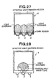
- FIG. 28 is a schematic diagram explaining how luminance non-uniformity develops in another surface light source device
- FIG. 29 is a schematic diagram explaining how luminance non-uniformity develops in a further surface light source device.
- FIG. 30 is a schematic diagram explaining how luminance non-uniformity develops in still another surface light source device.
- FIG. 1 is an exploded perspective view showing an embodiment of a surface light source device according to the present invention.
- the surface light source device includes a plurality of LEDs 2 , a light guide 4 , a light deflection element 6 , and a light reflection element 8 .
- the LEDs 2 are used as spot-like primary light sources.
- the light guide 4 is shaped like a rectangular plate, lies in an XY plane, receives the light from the LEDs 2 at a light-incoming end face, and emits the light from the light-outgoing face.
- the light deflection element 6 and the light reflection element 8 are arranged adjacent to the light guide.
- the light guide 4 has two major surfaces and four sides that connect the edges of one major surface to those of the other major surface.
- the LEDs 2 are juxtaposed on one of two opposing, substantially parallel sides of the light guide 4 (i.e., light incident side, or the left side in FIG. 1 ), and are spaced apart in the Y-axis direction by an appropriate distance.
- One of the LEDs lies between the two others.
- the spot-like light sources i.e., LEDs, which are the primary light sources, should better be used in as small a number as possible in order to reduce the power consumption. Nevertheless, many spot-like light sources may be arranged at regular intervals or adjacent to one another, depending on the size of the light guide 4 .
- the light guide 4 has light-incoming end faces 41 at its light-incident side.
- the light-incoming end faces 41 of the light guide 4 may be, for example, concave surf aces which have been formed by cutting the light-incident side.
- the light-emitting surface of each LED is convex so that it may well fit in a light-incoming end face of the light guide.
- the light-emitting surface of each LED and the corresponding light-incoming end face of the light guide may be flat.
- the faces 41 may be roughened by various methods, including cutting by use of a milling cutter, polishing using a grinding stone, sandpaper, buff or the like, blast process, electric discharge machining, electropolishing, chemical polishing, and the like.
- Blast particles used in the blast process may be spherical ones such as glass beads or polyhedral ones such as alumina beads. Polyhedral particles are preferred because they can serve to form rough surfaces that make light diverge greatly.
- the direction of processing, such as cutting or polishing may be adjusted, thereby to form anisotropic rough surfaces.
- the process of forming rough surfaces may be performed directly on the light-incoming end faces of the light guide.
- a mold having rough surfaces processed complementarily to the rough light-incoming end faces may be used to form the light-incoming end faces on the side of the light guide.
- the light-outgoing face 43 has a directional light-emitting mechanism that emits light from the light guide 4 in a direction inclined relative to the light-outgoing face 43 (that is, to the XY plane).
- the directional light-emitting mechanism comprises a rough surface (e.g., mat surface) or uneven structure formed surface (projections/depressions formed surface).
- the directional light-emitting mechanism emits light that propagates in a certain direction in the XZ plane defined by a normal to the light-outgoing face 43 (the Z-axis direction) and the X-axis direction perpendicular to the light-incoming end side.
- the direction of peak emission in the distribution inclines at angle of, for example, 10° to 40° relative to the light-outgoing face 43 .
- the distribution of light emitted therefore has a half-width value of, for example, 10° to 40°.
- the directional light-emitting mechanism will be later described in detail.
- the other major surface of the light guide 4 (i.e., rear surface: lower surface in FIG. 1 ) is an elongated lens formed surface 44 , which is an elongated structure formed surface.
- the elongated lens formed surface 44 has a plurality of elongated lenses as the elongated structure.
- the elongated lenses are arranged in parallel to one another, extending almost in the direction of the directivity of the light (i.e., the direction in which the light has a peak in the light-intensity distribution), in the plane (i.e., XY plane) that is parallel to the light-outgoing face 43 , emitted from the LEDs 2 and introduced into the light guide 4 .
- the term “directivity of the light introduced into the light guide 4 ” means a direction in the plane parallel to the light-outgoing face 43 (i.e. the XY plane), unless otherwise specifier.
- the directivity of the light introduced into the light guide 4 may be substantially the X-axis direction.
- the direction in which the elongated lenses 44 a extend can be the X-axis direction as shown in FIG. 2 . ( FIG. 2 shows the edges of the elongated lenses 44 a .)
- the direction in which the elongated lenses 44 a extend may deviate from the directivity of the light introduced into the light guide 4 unless it impairs the diversion of light.
- Such a direction is regarded as almost identical to the directivity of the light introduced into the light guide 4 .
- the elongated lenses 44 a should extend at an angle of 20° or less, preferably 10° or less, relative to the direction of the directivity of the light introduced into the light guide 4 . Since the elongated lenses extend so, the light introduced into the light guide diverges in the XY plane. Thus, dark regions will scarcely develop.
- the light deflection element 6 is arranged on the light-outgoing face 43 of the light guide 4 .
- Each of the two major surfaces of the light deflection element 6 is, as a whole, parallel to the XY plane.
- One major surface i.e., the major surface facing the light-outgoing face 43 of the light guide 4
- the other major surface is a light-emitting surface 62 .
- the light-emitting surface 62 is flat, extending in parallel to the light-outgoing face 43 of the light guide 4 .
- the light-incidence surface 61 is an elongated lens formed surface, on which a number of elongated lenses 61 a are arranged in parallel to one another.
- the elongated lenses 61 a on the light-incidence surface 61 extend in parallel to one another and almost at right angles to the direction of the directivity of the light introduced from the LEDs 2 into the light guide 4 .
- the elongated lenses 61 a extend in the Y-axis direction in the present embodiment.
- FIG. 3 shows how the an light deflection element 6 deflects light.
- This figure shows the direction in which the peak-emission light (i.e., the light at a peak in the distribution of light emitted) propagates in the XZ plane from the light guide 4 .
- the light emitted slantwise from the light-outgoing face 43 of the light guide 4 is incident on the first surface of each elongated lens 61 a and then totally reflected at the second surface of the elongated lens.
- the light so reflected is emitted in a direction that is substantially normal to the light-emitting surface 62 .
- the luminance in the direction normal to the light-emitting surface 62 can be sufficiently enhanced over a broad region, thanks to the action of the elongated lenses 44 a.
- FIG. 4 is a perspective view showing the light guide 4 , together with the LEDs 2 .
- This figure particularly illustrates the configuration of the light-outgoing face 43 of the light guide 4 .
- the directional light-emitting mechanism will be described hereunder in detail.
- the LEDs 2 (four LEDs in this embodiment) opposed to the flat light-incoming end faces 41 are arranged at substantially regular intervals.
- the direction of directivity, in the light guide 4 of the light beam emitted from each LED 2 and incident on the light-incoming end faces 41 is almost perpendicular to the light-incoming end faces 41 .
- the direction of directivity is identical with the X-axis direction shown in FIG. 1 in most cases.
- the light-emitting mechanism that the light-outgoing face 43 has may be a rough surface or a surface having uneven structures such as projections and depressions, as described above.
- the surface may have a number of dots or conical projections.
- the surface may be an elongated lens formed surface that have a number of elongated lenses such as elongated prisms, elongated lenticular lenses or V-grooves that extend substantially in perpendicular (Y-axis direction shown in FIG. 1 ) or substantially in parallel (X-axis direction shown in FIG. 1 ) to the direction of directivity of the light introduced into the light guide 4 .
- the elongated lenses are not limited to straight ones. They may be curved, surrounding the LEDs 2 (for example, arcuate ones concentrically surrounding LED 2 ).
- the rough surface or the surface having uneven structures, which constitute the light-emitting mechanism should have an average inclination angle ⁇ a falling within the range of 0.2 to 20° as measured by the method prescribed in ISO4287/1-1934 along the direction of directivity of the light introduced into the light guide, in order to render the luminance uniform in the light-outgoing face 43 .
- the average inclination angle ⁇ a should range from 0.3 to 10°. More preferably, it should range from 0.5 to 5°.
- the elongated lens formed surface having elongated lenses extending in the Y-axis direction is used as light-emitting mechanism, the elongated lenses should be arranged at pitch of 10 to 100 ⁇ m, preferably 10 to 80 ⁇ m, and more preferably 20 to 60 ⁇ m.
- the apex angle of the elongated lens should range from 140° to 179.6°, preferably from 156° to 179.4°, and more preferably from 164° to 179°.
- the average inclination angle ⁇ a of the rough surface or the surface having uneven structures such as an elongated lens formed surface, which constitute the light-emitting mechanism in the light guide 4 can be measured by determining the shape of the rough surface, etc. with a contact-stylus, surface-roughness meter as prescribed in ISO4287/1-1984 and then applying the inclination function f(x) (x: position in the measuring direction) to the following equations (1) and (2).
- ⁇ a (1 /L ) ⁇ o L
- ⁇ a tan ⁇ 1 ( ⁇ a ) (2)
- L is the length over which the measuring is performed, and ⁇ a is the tangent of the average inclination angle ⁇ a.
- the light-emitting mechanism in the light guide may have substance having a refractive index different from that of the main component of the light guide.
- the substance having such a refractive index may be dispersed in the light guide, in the form of fine particles.
- a layer having a different refractive index may be provided on a surface of the light guide or in the light guide.
- This substance should have a refractive index that differs by 0.002 to 0.3 from that of the main component of the light guide, preferably by 0.005 to 0.2, and more preferably by 0.01 to 0.1.
- the substance different in refractive index should better be fine particles, which can readily dispersed and can therefore facilitate the manufacture of the light guide.
- Silicon particles, styrene particles, particles of copolymer thereof, acryl particles, particles of copolymer thereof, inorganic particles, and the like can be exemplified as the fine particles.
- the concentration at which the fine particles are used should be 0.01 wt % to 10 wt %, preferably 0.1 wt % to 5 wt %, and more preferably 0.2 wt % to 3 wt %.
- the light-emitting mechanism should not be provided on the region 435 of the light-outgoing face 43 , which lies adjacent to the light-incoming end face 41 and which extends along the light-incoming end face 41 .
- the smooth region 435 on which the light-emitting mechanism is not provided and has an average inclination angle of substantially 0°, should better have a width of 7 mm or less, preferably 5 mm or less, and more preferably 4 mm or less.
- the light-emitting mechanism can suppress luminance non-uniformity and optimize the luminance distribution in the light-outgoing face 43 if it is so arranged that the light is not uniformly diffused in the light-outgoing face 43 of the light guide 4 .
- the average inclination angle of the light-emitting mechanism of the light guide may be increased or decreased for a region where the normal luminance decreases or increases, respectively, when measured after the light deflection element, light reflection element and the primary light sources have been arranged if the light-emitting mechanism assumes a uniform state in the entire effective light-emission region. Then, the luminance non-uniformity can be reduced.
- the luminance on the light-emitting surface be high at the center, gradually decreasing toward the edges.
- the center of the light-outgoing face 43 has a large average inclination angle and the other areas each have a region having smaller average inclination angle.
- a circular region 432 having a large average inclination angle is formed at the center of the light-outgoing face 43 , a region 433 having a relatively large average inclination angle is formed, surrounding the region 432 , a region 434 having a small average inclination angle is formed, closer to the light-incoming end faces 41 than the region 433 is, and the above-mentioned smooth region 435 is formed between the region 434 and the light-incoming end faces 41 .
- the regions 432 , 433 and 434 constitute the light-emitting mechanism.
- the region 434 of a small average inclination angle has an average inclination angle ⁇ a of 0.2 to 2°, preferably 0.5 to 1.5°.
- the region 433 of a relatively large average inclination angle has an average inclination angle ⁇ a of 1 to 10°, preferably 1.5 to 5°.
- the region 432 of a large average inclination angle has an average inclination angle ⁇ a of 1.5 to 20°, preferably 2 to 10°.
- high light diffusion regions 431 are formed on the light-outgoing face 43 of the light guide 4 . These regions 431 lie near the light-incoming end faces 41 and in front of the LEDs 2 , respectively. They extend straight in the direction of the directivity of the light introduced from the LEDs 2 into the light guide 4 (in most cases, extending in the X-axis direction shown in FIG. 1 ).
- the high light diffusion regions 431 are provided in the region 434 having a small average inclination angle. They have a larger average inclination angle than the region surrounding them, i.e., the region 434 . Therefore, the high light diffusion regions 431 have a higher light diffusion than that of the region 434 .
- the high light diffusion regions 431 constitute a light-emitting mechanism, too.
- the high light diffusion regions 431 are formed to prevent relatively dark regions from developing in front of the LEDs 2 due to the fact that the luminance becomes high at the positions where the light beams emitted from the LEDs 2 overlap one another.
- the difference in average inclination angle ⁇ a between each high light diffusion region 431 and the region 434 should be 0.1 to 1°. If the difference is less than 0.1°, it may not be possible to prevent dark regions from developing in front of the LEDs 2 . If the difference exceeds 1°, the high light diffusion region 431 may be too bright, inevitably causing luminance non-uniformity.
- the difference in average inclination angle ⁇ a between each high light diffusion region 431 and the region 434 is 0.3 to 0.7°, and more preferably 0.2 to 0.4°. It is desired that the high light diffusion regions 431 be so formed that the average inclination angle ⁇ a gradually changes at the boundaries with the surrounding region, in order to avoid the quality degradation such as great luminance changes resulting from sharp changes in light diffusion with respect to the region 434 .
- the high light diffusion regions 431 are elongated, either rectangular or triangular, extending substantially in the direction of the directivity of the light introduced into the light guide 4 . They should preferably have rounded corners or be shaped like an elongated circle, in order to avoid the quality degradation such as great luminance changes resulting from sharp changes in light diffusion with respect to the surrounding region. Thus, as shown in FIG. 4 , the high light diffusion regions 431 are shaped like a rectangle with rounded corners or like an elongated circle.
- the high light diffusion regions 431 may have a width and a length, which accord with dark regions to develop.
- the regions 431 preferably have a width of 0.5 to 5 mm and a length of 0.55 to 35 mm so that they may not be too bright and may have an aspect ratio of 1.1 to 7.
- the aspect ratio is a ratio of the minor axis (extending substantially at right angles to the direction of the directivity of the light introduced into the light guide 4 ) to the major axis (extending in the direction of the directivity of the light introduced into the light guide 4 ).
- the aspect ratio ranges from 3 to 5, the width ranges from 1.5 to 4.5 mm, and the length ranges from 5 to 15 mm.
- the positions where the high light diffusion regions 431 are formed can be selected in accordance with the dark regions to develop. In order not to become too bright and to prevent dark regions from developing in front of the LEDs 2 , the high light diffusion regions 431 should be positioned, with one end located at a distance of 0.5 to 7 mm from the corresponding light-incoming end face 41 and outside the effective light-emitting region.
- art uneven structure or projection-depression structure such as the elongated lenses 44 a formed on the light guide 4 should have an appropriate sectional shape.
- the appropriate shape is determined on the basis of an inclination angle (minute inclination angle) and a ratio (distribution) of angle components.
- the inclination angle pertains to a minute region or segment that is required, as described below, to define the cross section of the elongated uneven structure such as elongated lens.
- the ratio of angle components is based on the number of the segments having certain inclination angle or certain range of the inclination angle.
- a cross section that is substantially perpendicular to the direction in which the elongated uneven structure, e.g., elongated lens 44 a , extends is used as the basis of calculating the minute inclination angle and the distribution of angle components.
- the elongated uneven structures such as elongated lens 44 a , may not be completely parallel to one another.
- a curved cross section that intersects at right angles with the direction in which the individual elongated uneven structure (e.g., elongated lens) extends is employed (see FIG. 5B ).
- each repeated unit is divided into 100 segment.
- the number of repeated units of the cross section, which are to be extracted is not limited to five.
- the number of segments, into which the repeated units are divided is not limited to 500. They can be changed so long as the minute inclination angle and the distribution of angle components, both selected, are appropriate for the entire cross section.
- the absolute value of the angle (inclination angle) defined by the tangent of each segment and the plane in which the elongated uneven structure formed surface such as the elongated lens formed surface 44 lies is obtained first.
- the tangent is, for example, one at the center of the segment and can approximately a line that connects the ends of the segment as shown in FIG. 6B , and the above plane is level one independent of the actual elongated uneven structures such as elongated lenses.
- FIG. 7 shows an example of the frequency distribution of angle components.
- the ratio of the number of segments having angles falling within a specific range relative to the number of all the segments is obtained. This ratio is used as ratio of the angle components falling within that specific range. From the ratio of the angle components, the shape of the elongated uneven structures such as elongated lenses is determined. Assume that the ratio of the number of segments falling within 20 to 50° of the angle range relative to the number of all the segments is 35% in the case shown in FIG. 7 . Then, the ratio of the angle components falling within 20 to 50° of the angle range is regarded as being 35%.
- the left and right halves of every repeated unit of the cross section may be asymmetrical to each other.
- five repeated units are extracted.
- the left half of each unit is divided into 50 segments along the line, of the cross section, thus obtaining 250 segments in total.
- the right halt of each unit is divided into 50 segments along the line of the cross section, thus obtaining 250 segments in total.
- the absolute value of the angle (inclination angle) defined by the tangent of the segment and the plane in which the elongated uneven structure formed surface such as elongated lens formed surface 44 lies is then obtained.
- a frequency distribution of the absolute values of inclination angles for all the segments of any left half of the unit is determined for every 1°.
- a frequency distribution of the absolute values of inclination angles for all the segments of any right half of the unit is determined for every 1°.
- the number of repeated units, which are to extract, is not limited to five.
- the number of segments into which each unit is divided is not limited to the value specified above. They can be changed so long as the minute inclination angle and the frequency distribution, both selected, are appropriate for the entire cross section.
- the cross section of the elongated uneven structures may not be a simple one that consists of repeated identical units. Rather, it may be such an irregular one as illustrated in FIG. 9 . If this is the case, a part of the cross section, which is 500 ⁇ m long along the line of the cross section, is extracted and divided along the line of the cross section into 500 segments, each 1 ⁇ m long. Then, a frequency distribution for all the segments thus obtained is calculated in the same way as described above.
- the length of the part of the cross section, which is extracted is not limited to 500 ⁇ m.
- the number of segments, into which this part of the cross section is divided is not limited to 500. They can be changed so long as the minute inclination angle and the distribution frequency, both selected, are appropriate for the entire cross section.
- the shape of the valleys (the lowest parts and the vicinity thereof in the cross section) at the boundaries of the repeated units influences the optical performance of the device most if the cross section has a regular shape that consists of identical repeated units (that is, if the elongated uneven structures are elongated lenses).
- the inclination angle of the valleys of the elongated lenses is used to evaluate the optical performance of the device.
- the inclination angle is measured as follows. As mentioned above, five repeated units, for example, are extracted from the cross section of the elongated lens formed surface. The five repeated units are divided into 500 segments along the line of the cross section. Thus, each repeated unit is divided into 100 segments.
- each repeated unit five valleys at the boundaries between the repeated units are examined, obtaining a first average values of the inclination angles for six segments on the left side of each boundary and for six segments on the right side of the boundary. If the left and right halves of each repeated unit are symmetrical to each other, a second average value of the inclination angles of the above ten first average values is regarded as the inclination angle of the valley of the elongated lenses.
- the left and right halves of each repeated unit may be asymmetrical to each other.
- a third average value of the inclination angles of the above five first average values regarding the left halves is regarded as the inclination angle of the left side of the valley of the elongated lenses
- a fourth average value of the inclination angles of the above five first average values regarding the right halves is regarded as the inclination angle of the right side of the valley of the elongated lenses.
- Luminance non-uniformity that results in such dark regions as shown in FIG. 27 may be observed in the effective light-emitting region if the primary light sources are spiced at long intervals from one another and the effective light-emitting region is close to the light-incoming end face.
- the light introduced into the light guide must be sufficiently diverged in the XY plane near the primary light sources, that is, in the vicinity of the light-incoming end face, so that the light can be observed in a broad region through thus light deflection element 6 .
- each elongated lens 44 a which is located near the primary light sources, that is, in the vicinity of the light-incoming end face, is so shaped to make the light diverge well.
- the light introduced into the light guide is reflected by the elongated lenses 44 a and travels in the XY plane, propagating slantwise to the direction of the directivity of the light introduced into the light guide.
- the elongated lenses 44 a reflect this light, guiding the same again in the direction of the directivity of the light.
- the light introduced into the light guide diverges in the XY plane and yet travels in a direction almost perpendicular to the elongated lenses 61 a of the light deflection element 6 .
- the light therefore is observed diverging as viewed through the light deflection element 6 along a normal to the light-outgoing face.
- the angle components of 20 to 50° should exist in a ratio equal to or greater than a specific value.
- angle components of 25 to 50° should exist in a ratio equal to or greater than a specific value.
- angle components of 30 to 50° should exist in a ratio equal to or greater than a specific value.
- angle components of 35 to 50° should exist in a ratio equal to or greater than a specific value.
- angle components of 40 to 50° should exist in a ratio equal to or greater than a specific value. The higher the ratio is, the better to enhance this function.
- angle components of 20 to 50° should exist in a ratio of at least 10%.
- the angle components should exist in a ratio of at least 20%, and more preferably at least 30%.
- angle components of 25 to 50° should exist in a ratio of at least 10%.
- the angle components should exist in a ratio of at least 20%, and more preferably at least 30%.
- angle components of 25 to 50° should exist in a ratio of at least 20%.
- the angle components should exist in a ratio of at least 30%, and more preferably at least 40%.
- angle components of 30 to 50° should exist in a ratio of at least 5%, preferably at least 10%, and more preferably at least 15%.
- angle components of 30 to 50° should exist in a ratio of at least 10%.
- the angle components should exist in a ratio of at least 20%, and more preferably at least 30%.
- angle components of 35 to 50° should exist in a ratio of at least 9%, preferably at least 10%, and more preferably at least 20%.
- angle components of 40 to 50° should exist in it ratio of at least 2%, preferably at least 3%, and more preferably at least 5%.
- the light propagating slantwise to the direction of the directivity of the light introduced into the light guide in a plane parallel to the light-outgoing face should be directed, as much as possible, to the direction of the above directivity.
- the elongated lenses 44 a should have a curved cross section. More specifically, when, at least near the primary light sources, the ratio of the angle components of ⁇ ° to ⁇ °+10° ( ⁇ ° being a specific angle) in the sectional shape of each elongated lens 44 a is obtained for all the angles ⁇ ° of 0 to 80°, a maximum value of the ratio of the angle components should preferably be 60% or less, preferably 50% or less, more preferably 40% or less.
- the elongated lenses 44 a will have a more linear cross section. In this case, the light will more likely diverge in the particular direction, or undergo anisotropic diversion. Consequently, luminance non-uniformity will develop in the form of such slant bright lines as illustrated in FIG. 28 .
- the cross section of each elongated lens must have many angle components.
- more light beams will travel in the direction of the directivity of the light introduced into the light guide if the angle components of 35° or more increases in numbers.
- the luminance will increase in front of the primary light sources.
- any angle component of 50° or more has a small light-diverging action.
- it is desired that most segments of the cross section of the elongated lenses should have angle components of 60° or less, preferably 50° or less.
- the maximum value of the ratio of angle components ranging from ⁇ ° to ⁇ °+10° should preferably 15% or more, and more preferably 20% or more.
- the ratio of angle components of 40 to 50° should be 60% or less, preferably 50% or less, and more preferably 40% or less.
- the ratio of angle components of 35 to 50°, mentioned above, should be 90% or less, preferably 75% or less, and more preferably 60% or less.
- the ratio of angle components of 30 to 50°, mentioned above, should be 80% or less.
- the light-incoming end face 41 will be explained. If the light-incoming end face 41 is roughened, there is obtained a greater amount of light propagating slantwise to the direction of the directivity of the light introduced into the light guide in a plane parallel to the light-outgoing face 43 . The light therefore diverges more in the XY plane. Such dark regions as shown in FIG. 27 will become small. If the light much diverges, the light propagating slantwise will be reflected by the elongated lenses 44 a and will likely be emitted. Consequently, such bright lines as shown in FIG. 30 may develop at the largest angles of diversion.
- the valleys may have a large inclination angle near the primary light sources, and a small inclination angle in the effective light-emission region.
- the light diverges slantwise to the direction of the directivity of the light introduced into the light guide as it is reflected by the elongated lenses 44 a , and travels while being guided back toward the direction of the directivity of the light into the light guide.
- the light introduced into the light guide 4 spreads in the XY plane.
- more light is emitted in perpendicular to elongated prisms of a prism sheet, i.e. lens sheet used as the light deflection element 6 .
- the light looks as if spreading, as viewed through the prism sheet.
- the light greatly diverging, which causes luminance non-uniformity as shown in FIG.
- the region A should be switched to the region B when the region A expands to a position at least 0.1 mm, preferably at least 0.3 mm, more preferably at least 0.5 mm, before the effective light-emission region.
- the entire effective light-emission region may be changed to a region B as shown in FIG. 10A , or a part of the effective light-emission region may be changed to a region B as shown in FIG. 10B .
- the ratio of angle components of 30 to 50° be lower than that in the region A by at least 5%, or preferably by at least 8%.
- the valleys have an inclination angle smaller than that in the region A by at least 5°, preferably by at least 10°, or more preferably by at least 15°. If the difference in cross section between the regions A and B is too small, such luminance non-uniformity as shown in FIG. 30 may be less prevented than otherwise.
- the ratio of angle components of 30 to 50° be at most 40%, preferably at most 30%, and at least 5%, preferably at least 10%, more preferably at least 15%.
- the ratio of angle zorpronents of 35 to 50° be at most 30%, preferably at most 20%, and at least 2%, preferably at least 8%, more preferably at least 13%.
- the valleys have an inclination angle of at most 30°, preferably at most 25°, more Preferably at most 20°, and at least 5°, preferably at least 8°, more preferably at least 10°. If the difference between the regions A and B, in the ratio of angle components or the inclination angle of the valleys, is too large, such luminance non-uniformity as shown in FIG. 30 may be less prevented than otherwise. If this difference is too small, the light diverging in a region near the primary light sources cannot be reflected to the direction perpendicular to the elongated prisms of the prism sheet. In this case, the component of light which travels along the normal to the light-outgoing face decreases in magnitude. Consequently, the luminance as measured along the normal will decrease.
- the elongated lenses 44 a gradually change in shape at the boundary between the regions A and B. If the elongated lenses 44 a so change in shape, the projection of the structure of the boundary into the effective light-emission region can be avoided even if the region A is switched to the region B at the edge of the effective light-emission region (i.e., the boundary between the effective light-emission region and the region corresponding to the non-display region of the liquid crystal display device).
- One of the methods of changing a part of the elongated lens formed surface in shape is to roughen that part. If the elongated lens formed surface is roughened in part, the shape of the elongated lenses can be changed at least in part. The degree of this change Cay be continuously varied, thereby to change the shape of the elongated lenses gradually. Such luminance non-uniformity as shown in FIG. 29 can be eliminated by roughening the surfaces of the elongated lenses 44 a.
- the relation between the luminance distribution of the light emitted from each primary light source and the distance between the primary light sources should be made appropriate. More precisely, as shown in FIG. 11 , the normal luminance is measured over a region S which is 0.5 mm wide and spaced apart by 3 to 3.5 mm from the light-incoming edge of the effective light-emission region, at intervals of 1 mm in the lengthwise direction (Y-axis direction) of the region S. Then, the normal luminance thus measured is plotted with respect to the positions y [mm] where it has been measured.
- FIGS. 12A and 12B are graphs, each representing a relation between the luminance-measuring position y [mm] and the luminance.
- FIG. 12A shows the relation observed when the ratio is greater than 1.2.
- FIG. 12B shows the relation observed when the ratio is smaller than 0.8. If the ratio is too large, the light beams from any two adjacent primary light sources 2 much overlap each other and may form a bright line, ultimately forming a bright-dark pattern as shown in FIG. 13A .
- the light beams from any two adjacent primary light sources 2 scarcely overlap each other and may form bright lines in front of the primary light sources and a dark line at regions corresponding to areas between the primary light sources, ultimately forming a bright-dark pattern as shown in FIG. 13 B.
- the cross-sectional shape of the elongated lenses 44 a should preferably satisfy the following conditions in the vicinity of the primary light sources. That is, in the cross section, the ratio of the angle components of 35 to 60° or the ratio of the angle components of at most 15° is large in order to reduce the full width (distance) at half-maximum of the normal luminance. Conversely, in order to increase the full width (distance) at half-maximum of the normal luminance, the ratio of the angle components of 35 to 60° or the ratio of the angle components of at most 15° is small.
- the light propagating slantwise to the direction of the directivity of the light introduced into the light guide is reflected by the elongated lenses 44 a and emitted at a position very close to the primary light sources. In this case, more light will travel in the direction of the directivity of the light. If many angle components of 15° or less exist, the light hardly diverges due to the elongated lenses 44 a . In this case, too, more light rill travel in the direction of the directivity of the light.
- the distance between the primary light sources is 5 to 15 mm in most cases. Therefore, it is desired that, in a cross section of the elongated lenses, which satisfy the above-mentioned conditions, the ratio of the angle components of 35 to 60° should be 4 to 55%, or the ratio of the angle components of 15° or less should be 25 to 85%.
- the ratio of the angle components of 35 to 60° should be preferably 10 to 45%, more preferably 20 to 40%.
- the ratio of the angle components of 15° or less should be preferably 30 to 70%.
- the region A can be arranged near the primary light sources 2 , and the region B can be arranged partly in the entire effective light-emission region and partly in a zone that lies between the effective light-emission region and the region A.
- the region A can be arranged near the primary light sources 2 , and the region B can be arranged near the region A on a belt-like zone that extends so as to include the edge of the effective light-emission region on the side near the primary light sources 2 .
- the part of the effective light-emission region other than the region B may have the same structure as the region A.
- such a part of the effective light-emission region may have a structure different from that of the region A.
- the elongated lenses 44 a change in shape in the effective light-emission region.
- the shape should better be switched gradually so that the luminance non-uniformity resulting from the change in shape (i.e., switching of shale) may not conspicuous.
- island-shaped regions B as shown in FIG. 14 , contacting the region A and overlapping the effective light-emission region so as to include a part of the edge of the effective light-emission region on the side near the primary light sources 2 .
- the part of the effective light-emission region other than the regions B may have the same structure as the region A.
- such a part of the effective light-emission region may have a structure different from that of the region A.
- the elongated lenses 44 a change in shape in the effective light-emission region. Therefore, the shape should better be switched gradually so that the luminance non-uniformity resulting from the change in shape (i.e., switching of shape) may not conspicuous.
- a preferred cross section for the elongated lenses 44 a is defined by a convex curve as shown in FIG. 15 .
- Another preferred cross section for the elongated lenses 44 a is defined by concave curves as shown in FIG. 16 .
- Still another preferred cross section for the elongated lenses 44 a is defined by convex curves and concave curves alternately connected, as shown in FIG. 17 .
- a further preferred cross section for the elongated lenses 44 a is defined by a part of a polygon, i.e. a plurality of straight lines, as illustrated in FIG. 18 .
- Still another preferred cross section for the elongated lenses 44 a is defined by a combination of straight lines and a convex curve, as shown in FIG. 19 .
- the cross section is partly defined by a part of a polygon or straight lines, it should have an appropriate shape, in order not to cause such luminance non-uniformity as shown in FIG. 28 .
- the maximum value of the ratios of the angle components should preferably be 60% or less, preferably 50% or less and more preferably 40% or less.
- the cross section of the elongated lenses includes some straight lines, the surfaces corresponding to the straight lines reflect the light at greatly different angles, thus diverging the light very much. In this case, the light propagates in various directions, and such luminance non-uniformity as shown in FIG.
- a preferred shape is such a part of a polygon as shown in FIG. 18 , consisting of straight lines inclined to the elongated lens formed surface at about 40°, about 30° and about 20° or straight lines inclined to the elongated lens formed surface at about 40°, about 30°, about 20° and about 0°.
- Another preferred shape is the one shown in FIG. 19 , which satisfies this condition, too.
- the number of lines (sides) existing in the cross sections of FIGS. 18 and 19 is preferably 2 to 20, more preferably 3 to 15, more preferably 4 to 10. If the number of sides is too small, the light will not diverge in various directions, more possibly causing such luminance non-uniformity as shown in FIG. 28 . On the other hand, if the number of sides is too large, it will be difficult to manufacture a light guide having elongated lenses 44 a.
- a light guide is preferably used if it has a cross section of a curved line shape in a first region near the primary light sources and a cross section of a substantially polygonal shape such as a substantially triangular shape in a second region adjacent to the first region. More specifically, a light guide is preferably used if the ratio of angle components of ⁇ ° to ⁇ °+10° for all the angle components ⁇ ° of 0 to 80°, measured for the left and right inclined surfaces of the elongated lenses 44 a , is larger, at maximum, in the second region adjacent to the first region than in the first region near the primary light sources.
- the elongated lenses 44 a having the curved line cross section diverges the light without causing luminance non-uniformity in the first region near the primary light sources, and the elongated lenses 14 a having a substantially polygonal cross section (e.g., triangular one) converge the light in the second region adjacent to the first region.
- a substantially polygonal cross section e.g., triangular one
- the pitch at which the elongated lenses 44 a are arranged is preferably 10 to 100 ⁇ m, more preferably 10 to 80 ⁇ m, still more preferably 20 to 70 ⁇ m.
- the pitch of the elongated lenses 44 a may be the same, may differ or may gradually change, over all the elongated lenses 44 a , so long as it falls within the range specified above.
- the necessary spread angle is 110° or more, elongated lenses extending substantially in the direction of the directivity of the light introduced into the light guide may fail to make the light diverge sufficiently. If this is the case, it is recommendable to arrange, on the light-outgoing face or rear surface of the light guide 4 , elongated lenses 50 that extend slantwise to the direction of the directivity of the light introduced into the light guide (i.e., X-axis direction) as is illustrated in FIG. 20 . It is particularly desired that the elongated lenses should extend in almost the direction corresponding to the above necessary spread angle. Extending slantwise, the elongated lenses 50 can well reflect the light introduced into the light guide with so large angles that the elongated lenses 44 a cannot reflect it.
- the light can therefore be appropriately reflected by the elongated lenses 44 a .
- These elongated lenses 50 are formed, preferably in regions corresponding to those parts of the non-display region, which lies between the primary light sources. If the slant elongated lenses are not formed, these regions may be dark regions observed through the light deflection element 6 , i.e., prism sheet. In these regions, there is light that does not travel perpendicular to the elongated prisms of the prism sheet. Hence, the dark regions shown in FIG. 27 can be diminished if the light is deflected in these regions.
- the ratio of the angle components of 20 to 50°, measured in the same way as in case of the elongated lenses 44 a is preferably 10 to 80%. If the ratio is too small, the slant elongated lens will change the propagation direction of the light but a little. If the ratio is too large, new bright lines will develop, possibly causing new luminance non-uniformity.
- such a dot pattern 52 as shown in FIG. 21 may be formed on the light-outgoing face or rear surface of the light guide 4 .
- the dot pattern 52 can be formed by etching or laser process.
- the dot pattern 52 reflects the light components at so large an angle relative to the directivity of the light, that the elongated lenses 44 a cannot appropriately reflect.
- the elongated lenses 44 a can therefore appropriately reflect the light.
- the dots are formed, preferably in regions corresponding to those parts of the non-display region, which lie between the primary light sources. If the dot pattern is not formed, these regions may be dark regions observed through the prism sheet. In these regions, there is light that does not travel perpendicular to the elongated prisms of the prism sheet.
- each dot has such a cross section perpendicular to a line connecting the dot and a primary light source, in which the ratio of the angle components of 20 to 80°, measured in the same way as in case of the elongated lenses 44 a , is preferably 10 to 80%. If the ratio is too small, the dot pattern will change the propagation direction of the light but a little. If the ratio is too large, new bright lines will develop, possibly causing new luminance non-uniformity.
- a light-emitting mechanism is preferably provided on the light-outgoing face 43 of the light guide 4 as described above.
- the major surface (i.e., rear surface) opposed to the light-outgoing face 43 is preferably the elongated lens formed surface, on which elongated lenses 44 a are formed.
- the light-outgoing face 43 may be used as an elongated lens formed surface, and a light-emitting mechanism having high light diffusion regions may be provided on the opposite major surface.
- FIG. 22 is an exploded perspective view showing a part of a light guide according to this invention, together with the primary light source.
- the light-incoming end face 41 is an anisotropic rough surface.
- the anisotropic rough surface has an average inclination angle ⁇ a with respect to the Y-axis direction parallel to the light-outgoing face 43 .
- This average inclination angle ⁇ a is greater than the average inclination angle ⁇ a with respect to the Z direction perpendicular to the light-outgoing face 43 . Since the light-incoming end face 41 is rough, the light emitted from an LED 2 and introduced into the light guide 4 at the light-incoming end face 41 can diverge in the XY plane.
- the light does neither diverge excessively in the XZ plane and accordingly, nor is excessively emitted from the light guide 4 in the vicinity of the light-incoming end face 41 .
- the necessary intense light can be efficiently guided to a broad region on the light-outgoing face 43 . This helps to enhance the luminance uniformity.
- the anisotropic rough light-incoming end face 41 has an average inclination angle of preferably 3 to 30°, more preferably 4 to 25°, and still preferably 5 to 20°. If the average inclination angle is less than 3°, the above-mentioned effect may decrease. If the average inclination angle exceeds 30°, the light will not diverge more in the XY plane, inevitably reducing the luminance. To enhance the effect, it is desired that the average inclination angle should be 5° or less, preferably 3° or less, with respect to the Z direction that intersects at right angles to the light-outgoing face 43 .
- the anisotropic rough light-incoming end face 41 should have a region inclined at 8° or more with respect to the Y-axis direction parallel to the light-outgoing face 43 , a length of which is 5% or less of the measurement length of the face 41 . If this region inclined at 8° or more has a length greater than 5% of the measurement length of the face 41 , the light will excessively diverge in the XY plane and is excessively emitted from the light guide 4 in the vicinity of the light-incoming end face 41 , inevitably reducing the luminance.
- the anisotropic rough surface should preferably have a regular or irregular uneven structure composed of projections and depressions, extending in parallel to one another substantially in the Z direction. More precisely, the surface may be defined by elongated lenses that extend in parallel to one another substantially in the Z direction. The elongated lenses may be roughened at surface.
- the light guide 4 according to the present invention may be made of synthetic resin that has high transmittance.
- examples of such resin are methacrylic resin, acrylic resin, polycarbonate resin, polyester resin, vinyl chloride resin, and cyclic polyolefin resin.
- Methacrylic resin is most recommendable, because it excels in transmittance, thermal resistance, mechanical properties and process readiness.
- Methacrylic resin that contains at least 80 wt % of methyl methacrylate as main component is preferred.
- a plate of transparent synthetic resin may be formed by hot press by using a mold that has a desired surface structure.
- the surface structure may be formed and shaped by means of screen printing, extrusion molding or injection molding.
- the surface structure may be formed by using heat- or ultraviolet-curable resin.
- the high light diffusion regions 431 and other regions 432 , 433 and 434 which constitute the light-emitting mechanism of the light guide 4 according to the present invention, are formed by transferring the shape of the shape-transfer surface formed in a mold.
- a shield having an opening or openings corresponding to the region or regions to be formed on the surface of mold is arranged, if the light-emitting mechanism is formed by a rough surface.
- the mold is thereby covered, except a part or parts corresponding to the above region or regions, and is then subjected to blast process or etching.
- FIGS. 23 to 26 show specific examples of shields that are used in blast process to form a mold that has a shape-transfer surface for forming the light-outgoing face on the light guide.
- FIG. 23 shows a shield that has a circular opening having a radius (R) of 45 mm and corresponding to the regions 432 and 433 shown in FIG. 4 .
- FIG. 24 shows a shield that has a circular opening having a radius (R) of 17 mm and corresponding to the region 432 shown in FIG. 4 .
- FIG. 25 shows a shield that has four elongated openings each having a major axis 13.5 mm long and a minor axis 3 mm long and corresponding to the high light diffusion regions 431 shown in FIG. 4 .
- FIG. 26 shows a shield that has two openings each shaped like an isosceles right triangle having 4 mm-long sides and corresponding to those two corner areas (not shown) of the light-outgoing face, which are near the light-incoming end face.
- a mold for forming an uneven or projection-depression structure composes of dots or conical projections may have, in its shape-transfer surface, recesses that are complementary to the dots or projections.
- the shape of the elongated lenses 44 a formed on the light guide according to the present invention may be changed in part, by various methods.
- One method is to perform a blast process, on a mold having an elongated lens shape-transfer surface made by cutting or etching, either in part or as a whole.
- Another method is to polish, in part or as a whole, a mold having an elongated lens shape-transfer surface and to transfer the shape of the polished mold.
- Still another method is to perform a blast process on a molding product produced by using a first mold having an elongated lens shape-transfer surface, either in part or as a whole, and to transfer the shape of the molding product, thereby obtaining a second mold having an elongated lens shape-transfer surface.
- the distribution of ratio of angle components of the elongated lenses 44 a or the inclination angle of the valleys can be changed.
- the lenses provided on the light deflection element 6 may have various shapes, in accordance with the use of the surface light source device. They may be shaped like a prism, a lenticular lens, a fly-eye lens, a waving lens, or the like.
- the light deflection element 6 can be made of synthetic resin slaving high transmittance.
- examples of such resin are methacrylic resin, acrylic resin, polycarbonate resin, polyester resin, vinyl chloride resin, and cyclic polyolefin resin.
- Methacrylic resin is most recommendable, because it excels in transmittance, thermal resistance, mechanical properties and process readiness.
- Methacrylic resin that contains at least 80 wt % of methyl methacrylate as main component is preferred.
- a plate of transparent synthetic resin may be formed by hot press by using a mold that has a desired surface structure.
- the surface structure may be formed and shaped by means of screen printing, extrusion molding or injection molding, at the same time the element 6 is formed.
- the surface structure may be formed by using heat-curable or light-curable resin.
- the mold used may be produced by cutting or etching a work piece.
- a rough-surface structure or elongated lens formed structure, made of active energy-beam-curable resin may be formed on a transparent base such as transparent film or sheet made of polyester resin, acrylic resin, polycarbonate resin, vinyl chloride resin, polymethacrylimide resin or the like. Such a sheet may be bonded to a transparent base by means of adhesion, fusion or the like.
- the active energy-beam-curable resin may be multifunctional (meth)acrylic compound, vinyl compound, (meth)acrylic esters, allyl compound, metal salt of (meth)acrylic acid, or the like.
- the light reflection element 8 may be a plastic sheet that has, for example, a metal reflecting layer vapor-deposited on the surface.
- the light reflection element a may not be a reflecting sheet, but a light-reflecting layer formed on the major surface 44 of the light guide 4 , which faces away from the light-outgoing face.
- a reflecting member may be formed on the four end faces of the light guide 4 (but not on the light-incoming end face 41 ).
- the inclination angles of the cross-section segments of the light guide were measured as follows. A replica of the elongated lenses of the light guide was produced first. The replica was cut at a plane perpendicular to the direction in which the elongated lenses extended. The cut face was photographed with an optical microscope, an atomic microscope or the like, providing a magnified image of the cut face. The inclination angles of the cross-section segments were measured on the magnified image of the cut face. The frequency distribution of the absolute values of inclination angles for all segments and the inclination angles of the valleys were calculated by the method explained with reference to FIG. 6 . If the cross section is divided into segments having equal length as described above, however, a complex process must be performed to measure the positions in coordinates that represent the shape of the cross section. In this case, the method described below may be used to measure the positions in coordinates.
- the shape of cross section of the cut face is divided into segments having equal length in Y-axis direction.
- the frequency distribution of the absolute values of inclination angles for all the segments is calculated in the same manner as described in the above. Then, on the basis of the frequency distribution thus calculated, a value of [the frequency]/[cosine of inclination angle] is obtained for each inclination angle. The sum of the values thus calculated is calculated for all the segments. Next, a value of [the frequency]/[cosine of inclination angle]/[the sum of the values calculated in the above] is obtained for each inclination angle. This value is the frequency distribution that is valid when the shape of cross section is divided into segments having equal length.
- the average inclination angle was measured with a contact-stylus, surface-roughness meter (Surfcom 570A, Tokyo Seiki K.K.), using a 55° conical diamond needle (010-2528) having a diameter R of 1 ⁇ m, at a feed speed of 0.03 mm/sec, over a distance of 2 mm.
- the inclination of the referenced average line for the curve extracted was corrected.
- the center-line average values of curves obtained by differentiating the above curves were calculated in accordance with the equations (1) and (2) specified above.
- the surface of the plate was then subjected to a first blast process under the following conditions and was thereby roughened.
- the plate was blasted with glass beads (J220, Potters-Ballotini Co., Ltd.) applied through a nozzle spaced by 32 cm from the stainless steel plate, at pressure of 0.09 MPa, while moving the nozzle at 8.0 cm/s and moving the stainless steel plate in the Y-axis direction by 10 mm every time the nozzle moves across the plate.
- X-axis direction and “Y-axis direction,” both pertaining to the mold and the blank thereof, mean directions corresponding to the X-axis direction and Y-axis direction, respectively, pertaining to the light guide made by using the mold and shown in FIG. 1 , et seq.
- a shield of the type shown in FIG. 23 was positioned, in a relationship to the effective light-emission region as shown in the figure, at 7 cm above the stainless steel plate subjected to the first blast process. Then, the second blast process was performed in the same way as the first blast process, except that the nozzle was moved at 6.0 cm/s. The part of the stainless steel plate, which had been subjected to the second blast process and thereby roughened, had an average inclination angle ⁇ a of 1.8°. Thereafter, a shield of the type shown in FIG. 24 was positioned, in a relationship to the effective light-emission region as shown in the figure, at 7 cm above the stainless steel plate subjected to the second blast process.
- the third blast process was performed in the same way as the second blast process.
- a shield of the type shown in FIG. 25 was positioned, in a relationship to the effective light-emission region as shown in the figure, at 5 cm above the stainless steel plate subjected to the third blast process.
- the fourth blast process was then performed in the same way as the second blast process, except that the nozzle was roved at 3.5 cm/s.
- a shield of the type shown in FIG. 26 was positioned, in a relationship to the effective light-emission region as shown in the figure, at 2 cm above the stainless steel plate subjected to the fourth blast process.
- the fifth blast process was then performed in the same way as the second blast process, except that alumina particles having an average diameter of 30 ⁇ m (A400, Fujimi Incorporated) were applied through a nozzle at pressure of 0.6 MPa and the nozzle was moved at 1.5 cm/s.
- the first mold was produced.
- a quenched steel plate 34 mm thick, mirror-polished, having an effective light-emission region of 51 mm ⁇ 71 mm, was nickel-plated to have a nickel layer having thickness of 0.2 mm.
- the steel plate was then mirror-polished.
- On a surface of the steel plate a symmetrical lens pattern consisting of elongated lenses arranged at pitch of 50 ⁇ m and extending parallel to the 71-mm long sides, was formed by cutting.
- the steel plate was masked with an adhesive tape over a region that extends from one short side (51 mm long, corresponding to the light-incoming end face) by 3.5 mm.
- This plate was then subjected to a blast process, which was performed in the same way as the second blast process, except that glass beads having a particle diameter of 63 ⁇ m or less (J400, Potters-Ballotini Co., Ltd.) were applied at pressure of 0.2 MPa, while moving the nozzle at 3.8 cm/s.
- the second mold was thus formed, whose elongated lens-pattern transfer surface had been roughened in part.
- a quenched steel member 34 mm thick, mirror-polished, having an effective light-emission region having a size of 0.85 mm ⁇ 51 mm, was subjected to a blast process, which was performed in the same way as the second blast process, except that alumina particles having an average diameter of 30 ⁇ m (A400, Fujimi Incorporated) were applied at pressure of 0.008 MPa, while moving the nozzle at 5.0 cm/s and positioning the same 16 cm above the steel member.
- alumina particles having an average diameter of 30 ⁇ m A400, Fujimi Incorporated
- Injection molding was carried out, using the first mold, the second mold and the third mold for, respectively, transferring the light-outgoing face of a light guide, transferring the rear surface of the light guide and forming the light-incoming end face of the light guide.
- a transparent light guide was produced, which was made of transparent acrylic resin, shaped like a wedge, having 51-mm short sides and 71-mm long sides and thickness gradually decreasing from 0.85 mm (at the light-incoming end face) to 0.6 mm (at the opposite end face).
- One major surface of the light guide was a light-outgoing face having a high light diffusion region near the light-incoming end face.
- the other major surface of the light guide was an elongated lens formed surface.
- the planar light source device car be combined with a liquid crystal display device to provide a liquid crystal display which has an effective display region having a size of 46 mm ⁇ 61 mm and in which the light-incoming end face of the light guide is spaced by 6.25 mm from the effective display region.
- the light guide produced had an elongated lens formed surface having the following cross-sectional share.
- Region A Extending 3.5 mm from the light-incoming end face
- Region B Region other than region A
- a surface light source device was manufactured in the same way as in Example 1, except that the nozzle was moved at 5.0 cm/s in the fourth blast process.
- the high light diffusion region of the light guide produced had an average inclination angle ⁇ a of 1.5°. All LEDs were turned on, making the surface light source device emits light.
- the effective light-emission region of the device was examined for luminance non-uniformity. Such dark regions as shown in FIG. 27 , such bright lines as shown in FIG. 28 , such luminance non-uniformity as shown in FIG. 29 , resulting from the overlapping light beams from the light sources, such bright lines as shown in FIG. 30 , or dark regions in front of the LEDs were not observed at all.
- a surface light source device wan manufactured in the same way as in Example 1, except that particles were applied at pressure of 0.15 MPa in the fourth blast process.
- the high light diffusion region of the light guide produced had an average inclination angle ⁇ a of 1.7°. All LEDs were turned on, making the surface light source device emits light.
- the effective light-emission region of the device examined for luminance non-uniformity. Such dark regions as shown in FIG. 27 , such bright lines as shown in FIG. 28 , such luminance non-uniformity as shown in FIG. 29 , resulting from the overlapping light beams from the light sources, such bright lines as shown in FIG. 30 , or dark regions in front of the LEDs were not observed at all.
- a surface light source device was manufactured in the same way as in Example 1, except that the fourth blast process was not performed. All LEDs were turned on, making the surface light source device emits light. The effective light-emission region of the device was examined for luminance non-uniformity. Dark regions were observed in front of the respective LEDs.
Abstract
Description
-
- 2 LED
- 4 Light guide
- 41 Light-incoming end face
- 43 light-outgoing face
- 431 High light diffusion region
- 432 First region
- 433 Second region
- 434 Third region
- 435 Smooth region
- 44 Elongated lens formed surface
- 44 a Elongated lens
- 6 Light deflection element
- 61 Light-incidence surface
- 61 a Elongated lens
- 62 Light-emitting surface
- 8 Light reflection element
- 50 Slant elongated lens
- 52 Dot pattern
Δa=(1/L)∫o L|(d/dx)ƒ(x)|dx (1)
θa=tan−1(Δa) (2)
where L is the length over which the measuring is performed, and Δa is the tangent of the average inclination angle θa.
-
- 20° to 50°: 67%
- 25° to 50°: 51%
- 30° to 50°: 39%
- 35° to 50°: 26%
- 40° to 50°: 8%
- 15° or less: 33%
- 35° to 60°: 26%
- 40° to 60°: 8%
-
- 30° to 50°: 26%
Claims (9)
Applications Claiming Priority (3)
| Application Number | Priority Date | Filing Date | Title |
|---|---|---|---|
| JP2004282151 | 2004-09-28 | ||
| JP2004-282151 | 2004-09-28 | ||
| PCT/JP2005/017691 WO2006035743A1 (en) | 2004-09-28 | 2005-09-27 | Light guide for surface light source and surface light guide |
Publications (2)
| Publication Number | Publication Date |
|---|---|
| US20080031011A1 US20080031011A1 (en) | 2008-02-07 |
| US7815357B2 true US7815357B2 (en) | 2010-10-19 |
Family
ID=36118888
Family Applications (1)
| Application Number | Title | Priority Date | Filing Date |
|---|---|---|---|
| US11/663,767 Expired - Fee Related US7815357B2 (en) | 2004-09-28 | 2005-09-27 | Light guide for surface light source device and surface light source device |
Country Status (6)
| Country | Link |
|---|---|
| US (1) | US7815357B2 (en) |
| JP (1) | JP2006128093A (en) |
| KR (2) | KR20090015997A (en) |
| CN (1) | CN100510515C (en) |
| TW (1) | TWI344053B (en) |
| WO (1) | WO2006035743A1 (en) |
Cited By (5)
| Publication number | Priority date | Publication date | Assignee | Title |
|---|---|---|---|---|
| US20100283942A1 (en) * | 2007-12-28 | 2010-11-11 | Takehiro Murao | Illuminating device and liquid crystal display device |
| US20130265803A1 (en) * | 2012-04-06 | 2013-10-10 | Shenzhen China Star Optpelectronics Technology Co., Ltd. | Light Guide Plate and Backlight Module |
| US20140036531A1 (en) * | 2012-08-03 | 2014-02-06 | Samsung Display Co., Ltd. | Backlight Unit and Display Apparatus Having the same |
| US9293741B1 (en) | 2010-12-29 | 2016-03-22 | Greatbatch Ltd. | Mechanical conditioning by bead blasting lithium iodine cell case |
| US20200115263A1 (en) * | 2017-07-06 | 2020-04-16 | Hohai University | Nanometer photocatalyst-microbe composite multilayer light transmission combination carrier |
Families Citing this family (17)
| Publication number | Priority date | Publication date | Assignee | Title |
|---|---|---|---|---|
| US8107155B2 (en) * | 2006-10-06 | 2012-01-31 | Qualcomm Mems Technologies, Inc. | System and method for reducing visual artifacts in displays |
| WO2008045311A2 (en) | 2006-10-06 | 2008-04-17 | Qualcomm Mems Technologies, Inc. | Illumination device with built-in light coupler |
| TWI350360B (en) * | 2007-06-12 | 2011-10-11 | Omron Tateisi Electronics Co | Surface light source device |
| US20110032728A1 (en) * | 2008-04-04 | 2011-02-10 | Kyocera Corporation | Light Source Device, and Display Apparatus Provided with Such Light Source Device |
| US8118468B2 (en) * | 2008-05-16 | 2012-02-21 | Qualcomm Mems Technologies, Inc. | Illumination apparatus and methods |
| CN101498810B (en) * | 2009-03-25 | 2011-12-21 | 友达光电股份有限公司 | Light conducting plate and backlight module employing the same |
| JP5439051B2 (en) * | 2009-06-23 | 2014-03-12 | 三菱レイヨン株式会社 | Surface light source device and light guide used therefor |
| US8783890B2 (en) * | 2010-07-01 | 2014-07-22 | Sharp Kabushiki Kaisha | Illumination device, display device, television receiving device, and LED light source utilizing square shaped emission distributions |
| TWI420166B (en) | 2010-07-27 | 2013-12-21 | Young Lighting Technology Corp | Light guide unit and light source module |
| TWI443382B (en) * | 2010-08-31 | 2014-07-01 | Wintek Corp | Illumination device and lens thereof |
| TWI418897B (en) * | 2010-10-08 | 2013-12-11 | Asustek Comp Inc | Backlight module and display device and electronic device using the same |
| TW201523044A (en) * | 2013-12-02 | 2015-06-16 | Hon Hai Prec Ind Co Ltd | Light guide plate and backlight module having same |
| TWI582501B (en) * | 2016-01-04 | 2017-05-11 | 揚昇照明股份有限公司 | Light source module and display device |
| JP2019125519A (en) * | 2018-01-18 | 2019-07-25 | シャープ株式会社 | Luminaire and display device |
| USD1015279S1 (en) | 2018-07-09 | 2024-02-20 | Hoffman Enclosures Inc. | Rooftop junction box |
| US10594121B2 (en) | 2018-07-09 | 2020-03-17 | Vynckier Enclosure Systems, Inc. | Weatherproof multipurpose enclosure with integrated flashing |
| CN109212818A (en) * | 2018-09-30 | 2019-01-15 | 联想(北京)有限公司 | Liquid crystal display and its manufacturing method |
Citations (15)
| Publication number | Priority date | Publication date | Assignee | Title |
|---|---|---|---|---|
| JPH056401U (en) | 1991-07-09 | 1993-01-29 | オーツタイヤ株式会社 | Light guide device |
| JPH0727137B2 (en) | 1988-06-02 | 1995-03-29 | 三菱レイヨン株式会社 | Surface light source element |
| JPH07270624A (en) | 1994-03-30 | 1995-10-20 | Eeshitsuku Kk | Light transmission plate for surface light emission |
| JPH08179322A (en) | 1994-12-27 | 1996-07-12 | Fujitsu Kasei Kk | Backlight unit for liquid crystal display device |
| JPH09160035A (en) | 1995-12-14 | 1997-06-20 | Enplas Corp | Side light type surface light source device |
| US5718497A (en) * | 1991-11-28 | 1998-02-17 | Enplas Corporation | Surface light source device |
| US5854872A (en) * | 1996-10-08 | 1998-12-29 | Clio Technologies, Inc. | Divergent angle rotator system and method for collimating light beams |
| JP2002055675A (en) | 1999-09-17 | 2002-02-20 | Matsushita Electric Ind Co Ltd | Image display device |
| WO2002048608A1 (en) | 2000-12-14 | 2002-06-20 | Mitsubishi Rayon Co., Ltd. | Surface light source system and optical deflection element |
| US20030076669A1 (en) * | 2001-10-22 | 2003-04-24 | Kabushiki Kaisha Advanced Display | Surface light source device and liquid crystal display device using it |
| JP2004006326A (en) | 2002-04-22 | 2004-01-08 | Mitsubishi Rayon Co Ltd | Surface light source and photo conductive member therefor |
| US20040136173A1 (en) * | 2002-12-20 | 2004-07-15 | Kun-Jung Tsai | Surface light source device for liquid crystal display |
| US6791566B1 (en) | 1999-09-17 | 2004-09-14 | Matsushita Electric Industrial Co., Ltd. | Image display device |
| US20040228603A1 (en) * | 2003-03-06 | 2004-11-18 | Taiwan Nano Electro-Optical Technology Co., Ltd. | Backlighting device |
| US20050174803A1 (en) | 2002-04-22 | 2005-08-11 | Yasuko Hayashi | Surface light source device and light guide used therefor |
-
2005
- 2005-09-27 US US11/663,767 patent/US7815357B2/en not_active Expired - Fee Related
- 2005-09-27 WO PCT/JP2005/017691 patent/WO2006035743A1/en active Application Filing
- 2005-09-27 CN CNB2005800325318A patent/CN100510515C/en not_active Expired - Fee Related
- 2005-09-27 KR KR1020087031732A patent/KR20090015997A/en not_active Application Discontinuation
- 2005-09-27 KR KR1020077009520A patent/KR100889431B1/en not_active IP Right Cessation
- 2005-09-27 JP JP2005280736A patent/JP2006128093A/en active Pending
- 2005-09-28 TW TW094133680A patent/TWI344053B/en not_active IP Right Cessation
Patent Citations (16)
| Publication number | Priority date | Publication date | Assignee | Title |
|---|---|---|---|---|
| JPH0727137B2 (en) | 1988-06-02 | 1995-03-29 | 三菱レイヨン株式会社 | Surface light source element |
| JPH056401U (en) | 1991-07-09 | 1993-01-29 | オーツタイヤ株式会社 | Light guide device |
| US5718497A (en) * | 1991-11-28 | 1998-02-17 | Enplas Corporation | Surface light source device |
| JPH07270624A (en) | 1994-03-30 | 1995-10-20 | Eeshitsuku Kk | Light transmission plate for surface light emission |
| JPH08179322A (en) | 1994-12-27 | 1996-07-12 | Fujitsu Kasei Kk | Backlight unit for liquid crystal display device |
| JPH09160035A (en) | 1995-12-14 | 1997-06-20 | Enplas Corp | Side light type surface light source device |
| US5854872A (en) * | 1996-10-08 | 1998-12-29 | Clio Technologies, Inc. | Divergent angle rotator system and method for collimating light beams |
| US6791566B1 (en) | 1999-09-17 | 2004-09-14 | Matsushita Electric Industrial Co., Ltd. | Image display device |
| JP2002055675A (en) | 1999-09-17 | 2002-02-20 | Matsushita Electric Ind Co Ltd | Image display device |
| WO2002048608A1 (en) | 2000-12-14 | 2002-06-20 | Mitsubishi Rayon Co., Ltd. | Surface light source system and optical deflection element |
| US20020163790A1 (en) | 2000-12-14 | 2002-11-07 | Mitsubishi Rayon Co., Ltd. | Planar light source system and light deflecting device therefor |
| US20030076669A1 (en) * | 2001-10-22 | 2003-04-24 | Kabushiki Kaisha Advanced Display | Surface light source device and liquid crystal display device using it |
| JP2004006326A (en) | 2002-04-22 | 2004-01-08 | Mitsubishi Rayon Co Ltd | Surface light source and photo conductive member therefor |
| US20050174803A1 (en) | 2002-04-22 | 2005-08-11 | Yasuko Hayashi | Surface light source device and light guide used therefor |
| US20040136173A1 (en) * | 2002-12-20 | 2004-07-15 | Kun-Jung Tsai | Surface light source device for liquid crystal display |
| US20040228603A1 (en) * | 2003-03-06 | 2004-11-18 | Taiwan Nano Electro-Optical Technology Co., Ltd. | Backlighting device |
Cited By (8)
| Publication number | Priority date | Publication date | Assignee | Title |
|---|---|---|---|---|
| US20100283942A1 (en) * | 2007-12-28 | 2010-11-11 | Takehiro Murao | Illuminating device and liquid crystal display device |
| US9293741B1 (en) | 2010-12-29 | 2016-03-22 | Greatbatch Ltd. | Mechanical conditioning by bead blasting lithium iodine cell case |
| US10141545B2 (en) | 2010-12-29 | 2018-11-27 | Greatbatch Ltd. | Mechanical conditioning by bead blasting lithium iodine cell case |
| US20130265803A1 (en) * | 2012-04-06 | 2013-10-10 | Shenzhen China Star Optpelectronics Technology Co., Ltd. | Light Guide Plate and Backlight Module |
| US20140036531A1 (en) * | 2012-08-03 | 2014-02-06 | Samsung Display Co., Ltd. | Backlight Unit and Display Apparatus Having the same |
| US9291765B2 (en) * | 2012-08-03 | 2016-03-22 | Samsung Display Co., Ltd. | Backlight unit and display apparatus having the same |
| US20200115263A1 (en) * | 2017-07-06 | 2020-04-16 | Hohai University | Nanometer photocatalyst-microbe composite multilayer light transmission combination carrier |
| US10889517B2 (en) * | 2017-07-06 | 2021-01-12 | Hohai University | Nanometer photocatalyst-microbe composite multilayer light transmission combination carrier |
Also Published As
| Publication number | Publication date |
|---|---|
| TW200617559A (en) | 2006-06-01 |
| CN101027521A (en) | 2007-08-29 |
| KR100889431B1 (en) | 2009-03-23 |
| TWI344053B (en) | 2011-06-21 |
| JP2006128093A (en) | 2006-05-18 |
| WO2006035743A1 (en) | 2006-04-06 |
| US20080031011A1 (en) | 2008-02-07 |
| CN100510515C (en) | 2009-07-08 |
| KR20090015997A (en) | 2009-02-12 |
| KR20070068425A (en) | 2007-06-29 |
Similar Documents
| Publication | Publication Date | Title |
|---|---|---|
| US7815357B2 (en) | Light guide for surface light source device and surface light source device | |
| KR100967755B1 (en) | Surface light source device and light guide used therefor | |
| US7736045B2 (en) | Area light source and lightguide used therefore | |
| US6799859B1 (en) | Surface illuminant device and prism sheet used therefor | |
| EP1348994B1 (en) | Light source device | |
| JP2004006326A (en) | Surface light source and photo conductive member therefor | |
| JP2006294256A (en) | Surface light source device and light guide body therefor | |
| KR100977941B1 (en) | Light deflector and light source device | |
| JP4778279B2 (en) | Optical mixing element and surface light source device using the same | |
| KR100927513B1 (en) | Surface light source unit-use light guide and production method therefor and surface light source unit | |
| JP2006108032A (en) | Light guide body for surface light source, its manufacturing method as well as surface light source device | |
| JP2004233938A (en) | Optical deflection element and light source device | |
| JP4761422B2 (en) | Surface light source device and light guide used therefor | |
| JP2003132720A (en) | Surface lightsource device | |
| KR100776863B1 (en) | Surface light source unit and light guide using it | |
| JP2009266643A (en) | Light guide body, and surface light source device using the same | |
| JP2010192198A (en) | Light guide body for surface light source device, and surface light source device | |
| JP2002258059A (en) | Light guide for surface light source unit and surface light source unit |
Legal Events
| Date | Code | Title | Description |
|---|---|---|---|
| AS | Assignment |
Owner name: MITSUBISHI RAYON CO., LTD., JAPAN Free format text: ASSIGNMENT OF ASSIGNORS INTEREST;ASSIGNORS:HAYASHI, KENTARO;YAMASHITA, TOMOYOSHI;REEL/FRAME:019120/0765 Effective date: 20070322 |
|
| STCF | Information on status: patent grant |
Free format text: PATENTED CASE |
|
| FEPP | Fee payment procedure |
Free format text: PAYOR NUMBER ASSIGNED (ORIGINAL EVENT CODE: ASPN); ENTITY STATUS OF PATENT OWNER: LARGE ENTITY |
|
| FPAY | Fee payment |
Year of fee payment: 4 |
|
| AS | Assignment |
Owner name: MITSUBISHI CHEMICAL CORPORATION, JAPAN Free format text: CHANGE OF NAME;ASSIGNOR:MITSUBISHI RAYON CO., LTD.;REEL/FRAME:043750/0834 Effective date: 20170401 |
|
| MAFP | Maintenance fee payment |
Free format text: PAYMENT OF MAINTENANCE FEE, 8TH YEAR, LARGE ENTITY (ORIGINAL EVENT CODE: M1552) Year of fee payment: 8 |
|
| FEPP | Fee payment procedure |
Free format text: MAINTENANCE FEE REMINDER MAILED (ORIGINAL EVENT CODE: REM.); ENTITY STATUS OF PATENT OWNER: LARGE ENTITY |
|
| LAPS | Lapse for failure to pay maintenance fees |
Free format text: PATENT EXPIRED FOR FAILURE TO PAY MAINTENANCE FEES (ORIGINAL EVENT CODE: EXP.); ENTITY STATUS OF PATENT OWNER: LARGE ENTITY |
|
| STCH | Information on status: patent discontinuation |
Free format text: PATENT EXPIRED DUE TO NONPAYMENT OF MAINTENANCE FEES UNDER 37 CFR 1.362 |
|
| FP | Lapsed due to failure to pay maintenance fee |
Effective date: 20221019 |