US7819185B2 - Expandable tubular - Google Patents
Expandable tubular Download PDFInfo
- Publication number
- US7819185B2 US7819185B2 US11/573,589 US57358905A US7819185B2 US 7819185 B2 US7819185 B2 US 7819185B2 US 57358905 A US57358905 A US 57358905A US 7819185 B2 US7819185 B2 US 7819185B2
- Authority
- US
- United States
- Prior art keywords
- tubular member
- expansion
- expandable tubular
- expandable
- filed
- Prior art date
- Legal status (The legal status is an assumption and is not a legal conclusion. Google has not performed a legal analysis and makes no representation as to the accuracy of the status listed.)
- Expired - Fee Related, expires
Links
Images


Classifications
-
- E—FIXED CONSTRUCTIONS
- E21—EARTH DRILLING; MINING
- E21B—EARTH DRILLING, e.g. DEEP DRILLING; OBTAINING OIL, GAS, WATER, SOLUBLE OR MELTABLE MATERIALS OR A SLURRY OF MINERALS FROM WELLS
- E21B43/00—Methods or apparatus for obtaining oil, gas, water, soluble or meltable materials or a slurry of minerals from wells
- E21B43/02—Subsoil filtering
- E21B43/10—Setting of casings, screens, liners or the like in wells
- E21B43/103—Setting of casings, screens, liners or the like in wells of expandable casings, screens, liners, or the like
-
- E—FIXED CONSTRUCTIONS
- E21—EARTH DRILLING; MINING
- E21B—EARTH DRILLING, e.g. DEEP DRILLING; OBTAINING OIL, GAS, WATER, SOLUBLE OR MELTABLE MATERIALS OR A SLURRY OF MINERALS FROM WELLS
- E21B17/00—Drilling rods or pipes; Flexible drill strings; Kellies; Drill collars; Sucker rods; Cables; Casings; Tubings
- E21B17/02—Couplings; joints
- E21B17/04—Couplings; joints between rod or the like and bit or between rod and rod or the like
- E21B17/042—Threaded
-
- E—FIXED CONSTRUCTIONS
- E21—EARTH DRILLING; MINING
- E21B—EARTH DRILLING, e.g. DEEP DRILLING; OBTAINING OIL, GAS, WATER, SOLUBLE OR MELTABLE MATERIALS OR A SLURRY OF MINERALS FROM WELLS
- E21B17/00—Drilling rods or pipes; Flexible drill strings; Kellies; Drill collars; Sucker rods; Cables; Casings; Tubings
- E21B17/02—Couplings; joints
- E21B17/08—Casing joints
-
- E—FIXED CONSTRUCTIONS
- E21—EARTH DRILLING; MINING
- E21B—EARTH DRILLING, e.g. DEEP DRILLING; OBTAINING OIL, GAS, WATER, SOLUBLE OR MELTABLE MATERIALS OR A SLURRY OF MINERALS FROM WELLS
- E21B29/00—Cutting or destroying pipes, packers, plugs, or wire lines, located in boreholes or wells, e.g. cutting of damaged pipes, of windows; Deforming of pipes in boreholes or wells; Reconditioning of well casings while in the ground
-
- E—FIXED CONSTRUCTIONS
- E21—EARTH DRILLING; MINING
- E21B—EARTH DRILLING, e.g. DEEP DRILLING; OBTAINING OIL, GAS, WATER, SOLUBLE OR MELTABLE MATERIALS OR A SLURRY OF MINERALS FROM WELLS
- E21B43/00—Methods or apparatus for obtaining oil, gas, water, soluble or meltable materials or a slurry of minerals from wells
- E21B43/02—Subsoil filtering
- E21B43/10—Setting of casings, screens, liners or the like in wells
- E21B43/103—Setting of casings, screens, liners or the like in wells of expandable casings, screens, liners, or the like
- E21B43/105—Expanding tools specially adapted therefor
-
- E—FIXED CONSTRUCTIONS
- E21—EARTH DRILLING; MINING
- E21B—EARTH DRILLING, e.g. DEEP DRILLING; OBTAINING OIL, GAS, WATER, SOLUBLE OR MELTABLE MATERIALS OR A SLURRY OF MINERALS FROM WELLS
- E21B43/00—Methods or apparatus for obtaining oil, gas, water, soluble or meltable materials or a slurry of minerals from wells
- E21B43/02—Subsoil filtering
- E21B43/10—Setting of casings, screens, liners or the like in wells
- E21B43/103—Setting of casings, screens, liners or the like in wells of expandable casings, screens, liners, or the like
- E21B43/106—Couplings or joints therefor
-
- F—MECHANICAL ENGINEERING; LIGHTING; HEATING; WEAPONS; BLASTING
- F16—ENGINEERING ELEMENTS AND UNITS; GENERAL MEASURES FOR PRODUCING AND MAINTAINING EFFECTIVE FUNCTIONING OF MACHINES OR INSTALLATIONS; THERMAL INSULATION IN GENERAL
- F16L—PIPES; JOINTS OR FITTINGS FOR PIPES; SUPPORTS FOR PIPES, CABLES OR PROTECTIVE TUBING; MEANS FOR THERMAL INSULATION IN GENERAL
- F16L55/00—Devices or appurtenances for use in, or in connection with, pipes or pipe systems
- F16L55/16—Devices for covering leaks in pipes or hoses, e.g. hose-menders
- F16L55/162—Devices for covering leaks in pipes or hoses, e.g. hose-menders from inside the pipe
- F16L55/165—Devices for covering leaks in pipes or hoses, e.g. hose-menders from inside the pipe a pipe or flexible liner being inserted in the damaged section
- F16L55/1652—Devices for covering leaks in pipes or hoses, e.g. hose-menders from inside the pipe a pipe or flexible liner being inserted in the damaged section the flexible liner being pulled into the damaged section
- F16L55/1653—Devices for covering leaks in pipes or hoses, e.g. hose-menders from inside the pipe a pipe or flexible liner being inserted in the damaged section the flexible liner being pulled into the damaged section and being pressed into contact with the pipe by a tool which moves inside along the pipe
-
- F—MECHANICAL ENGINEERING; LIGHTING; HEATING; WEAPONS; BLASTING
- F16—ENGINEERING ELEMENTS AND UNITS; GENERAL MEASURES FOR PRODUCING AND MAINTAINING EFFECTIVE FUNCTIONING OF MACHINES OR INSTALLATIONS; THERMAL INSULATION IN GENERAL
- F16L—PIPES; JOINTS OR FITTINGS FOR PIPES; SUPPORTS FOR PIPES, CABLES OR PROTECTIVE TUBING; MEANS FOR THERMAL INSULATION IN GENERAL
- F16L55/00—Devices or appurtenances for use in, or in connection with, pipes or pipe systems
- F16L55/16—Devices for covering leaks in pipes or hoses, e.g. hose-menders
- F16L55/162—Devices for covering leaks in pipes or hoses, e.g. hose-menders from inside the pipe
- F16L55/165—Devices for covering leaks in pipes or hoses, e.g. hose-menders from inside the pipe a pipe or flexible liner being inserted in the damaged section
- F16L55/1657—Devices for covering leaks in pipes or hoses, e.g. hose-menders from inside the pipe a pipe or flexible liner being inserted in the damaged section lengths of rigid pipe being inserted
Definitions
- This disclosure relates generally to oil and gas exploration, and in particular to forming and repairing wellbore casings to facilitate oil and gas exploration.
- a method of forming a tubular liner within a preexisting structure includes positioning a tubular assembly within the preexisting structure; and radially expanding and plastically deforming the tubular assembly within the preexisting structure, wherein, prior to the radial expansion and plastic deformation of the tubular assembly, a predetermined portion of the tubular assembly has a lower yield point than another portion of the tubular assembly.
- an expandable tubular member that includes a steel alloy including: 0.065% C, 1.44% Mn, 0.01% P, 0.002% S, 0.24% Si, 0.01% Cu, 0.01% Ni, and 0.02% Cr.
- an expandable tubular member that includes a steel alloy including: 0.18% C, 1.28% Mn, 0.017% P, 0.004% S, 0.29% Si, 0.01% Cu, 0.01% Ni, and 0.03% Cr.
- an expandable tubular member that includes a steel alloy including: 0.08% C, 0.82% Mn, 0.006% P, 0.003% S, 0.30% Si, 0.16% Cu, 0.05% Ni, and 0.05% Cr.
- an expandable tubular member that includes a steel alloy including: 0.02% C, 1.31% Mn, 0.02% P, 0.001% S, 0.45% Si, 9.1% Ni, and 18.7% Cr.
- an expandable tubular member wherein the yield point of the expandable tubular member is at most about 46.9 ksi prior to a radial expansion and plastic deformation; and wherein the yield point of the expandable tubular member is at least about 65.9 ksi after the radial expansion and plastic deformation.
- an expandable tubular member wherein a yield point of the expandable tubular member after a radial expansion and plastic deformation is at least about 40% greater than the yield point of the expandable tubular member prior to the radial expansion and plastic deformation.
- an expandable tubular member wherein the anisotropy of the expandable tubular member, prior to the radial expansion and plastic deformation, is at least about 1.48.
- an expandable tubular member wherein the yield point of the expandable tubular member is at most about 57.8 ksi prior to the radial expansion and plastic deformation; and wherein the yield point of the expandable tubular member is at least about 74.4 ksi after the radial expansion and plastic deformation.
- an expandable tubular member wherein the yield point of the expandable tubular member after a radial expansion and plastic deformation is at least about 28% greater than the yield point of the expandable tubular member prior to the radial expansion and plastic deformation.
- an expandable tubular member wherein the anisotropy of the expandable tubular member, prior to the radial expansion and plastic deformation, is at least about 1.04.
- an expandable tubular member wherein the anisotropy of the expandable tubular member, prior to the radial expansion and plastic deformation, is at least about 1.92.
- an expandable tubular member wherein the anisotropy of the expandable tubular member, prior to the radial expansion and plastic deformation, is at least about 1.34.
- an expandable tubular member wherein the anisotropy of the expandable tubular member, prior to the radial expansion and plastic deformation, ranges from about 1.04 to about 1.92.
- an expandable tubular member wherein the yield point of the expandable tubular member, prior to the radial expansion and plastic deformation, ranges from about 47.6 ksi to about 61.7 ksi.
- an expandable tubular member wherein the expandability coefficient of the expandable tubular member, prior to the radial expansion and plastic deformation, is greater than 0.12.
- an expandable tubular member is provided, wherein the expandability coefficient of the expandable tubular member is greater than the expandability coefficient of another portion of the expandable tubular member.
- an expandable tubular member wherein the tubular member has a higher ductility and a lower yield point prior to a radial expansion and plastic deformation than after the radial expansion and plastic deformation.
- a method of radially expanding and plastically deforming a tubular assembly including a first tubular member coupled to a second tubular member includes radially expanding and plastically deforming the tubular assembly within a preexisting structure, and using less power to radially expand each unit length of the first tubular member than to radially expand each unit length of the second tubular member.
- a system for radially expanding and plastically deforming a tubular assembly including a first tubular member coupled to a second tubular member includes means for radially expanding the tubular assembly within a preexisting structure, and means for using less power to radially expand each unit length of the first tubular member than required to radially expand each unit length of the second tubular member.
- a method of manufacturing a tubular member includes processing a tubular member until the tubular member is characterized by one or more intermediate characteristics; positioning the tubular member within a preexisting structure, and processing the tubular member within the preexisting structure until the tubular member is characterized one or more final characteristics.
- an apparatus that includes an expandable tubular assembly; and an expansion device coupled to the expandable tubular assembly; wherein a predetermined portion of the expandable tubular assembly has a lower yield point than another portion of the expandable tubular assembly.
- an expandable tubular member wherein a yield point of the expandable tubular member after a radial expansion and plastic deformation is at least about 5.8% greater than the yield point of the expandable tubular member prior to the radial expansion and plastic deformation.
- a method of determining the expandability of a selected tubular member includes determining an anisotropy value for the selected tubular member, determining a strain hardening value for the selected tubular member; and multiplying the anisotropy value times the strain hardening value to generate an expandability value for the selected tubular member.
- a method of radially expanding and plastically deforming tubular members includes selecting a tubular member; determining an anisotropy value for the selected tubular member; determining a strain hardening value for the selected tubular member; multiplying the anisotropy value times the strain hardening value to generate an expandability value for the selected tubular member; and if the anisotropy value is greater than 0.12, then radially expanding and plastically deforming the selected tubular member.
- a radially expandable tubular member apparatus includes a first tubular member; a second tubular member engaged with the first tubular member forming a joint; and a sleeve overlapping and coupling the first and second tubular members at the joint; wherein, prior to a radial expansion and plastic deformation of the apparatus, a predetermined portion of the apparatus has a lower yield point than another portion of the apparatus.
- a radially expandable tubular member apparatus includes: a first tubular member; a second tubular member engaged with the first tubular member forming a joint; a sleeve overlapping and coupling the first and second tubular members at the joint; the sleeve having opposite tapered ends and a flange engaged in a recess formed in an adjacent tubular member; and one of the tapered ends being a surface formed on the flange; wherein, prior to a radial expansion and plastic deformation of the apparatus, a predetermined portion of the apparatus has a lower yield point than another portion of the apparatus.
- a method of joining radially expandable tubular members includes: providing a first tubular member; engaging a second tubular member with the first tubular member to form a joint; providing a sleeve; mounting the sleeve for overlapping and coupling the first and second tubular members at the joint; wherein the first tubular member, the second tubular member, and the sleeve define a tubular assembly; and radially expanding and plastically deforming the tubular assembly; wherein, prior to the radial expansion and plastic deformation, a predetermined portion of the tubular assembly has a lower yield point than another portion of the tubular assembly.
- a method of joining radially expandable tubular members includes providing a first tubular member; engaging a second tubular member with the first tubular member to form a joint; providing a sleeve having opposite tapered ends and a flange, one of the tapered ends being a surface formed on the flange; mounting the sleeve for overlapping and coupling the first and second tubular members at the joint, wherein the flange is engaged in a recess formed in an adjacent one of the tubular members; wherein the first tubular member, the second tubular member, and the sleeve define a tubular assembly; and radially expanding and plastically deforming the tubular assembly; wherein, prior to the radial expansion and plastic deformation, a predetermined portion of the tubular assembly has a lower yield point than another portion of the tubular assembly.
- an expandable tubular assembly includes a first tubular member; a second tubular member coupled to the first tubular member; a first threaded connection for coupling a portion of the first and second tubular members; a second threaded connection spaced apart from the first threaded connection for coupling another portion of the first and second tubular members; a tubular sleeve coupled to and receiving end portions of the first and second tubular members; and a sealing element positioned between the first and second spaced apart threaded connections for sealing an interface between the first and second tubular member; wherein the sealing element is positioned within an annulus defined between the first and second tubular members; and wherein, prior to a radial expansion and plastic deformation of the assembly, a predetermined portion of the assembly has a lower yield point than another portion of the apparatus.
- a method of joining radially expandable tubular members includes: providing a first tubular member; providing a second tubular member; providing a sleeve; mounting the sleeve for overlapping and coupling the first and second tubular members; threadably coupling the first and second tubular members at a first location; threadably coupling the first and second tubular members at a second location spaced apart from the first location; sealing an interface between the first and second tubular members between the first and second locations using a compressible sealing element, wherein the first tubular member, second tubular member, sleeve, and the sealing element define a tubular assembly; and radially expanding and plastically deforming the tubular assembly; wherein, prior to the radial expansion and plastic deformation, a predetermined portion of the tubular assembly has a lower yield point than another portion of the tubular assembly.
- an expandable tubular member wherein the carbon content of the tubular member is less than or equal to 0.12 percent; and wherein the carbon equivalent value for the tubular member is less than 0.21.
- an expandable tubular member wherein the carbon content of the tubular member is greater than 0.12 percent; and wherein the carbon equivalent value for the tubular member is less than 0.36.
- a method of selecting tubular members for radial expansion and plastic deformation includes selecting a tubular member from a collection of tubular member; determining a carbon content of the selected tubular member; determining a carbon equivalent value for the selected tubular member; and if the carbon content of the selected tubular member is less than or equal to 0.12 percent and the carbon equivalent value for the selected tubular member is less than 0.21, then determining that the selected tubular member is suitable for radial expansion and plastic deformation.
- a method of selecting tubular members for radial expansion and plastic deformation includes selecting a tubular member from a collection of tubular member; determining a carbon content of the selected tubular member; determining a carbon equivalent value for the selected tubular member; and if the carbon content of the selected tubular member is greater than 0.12 percent and the carbon equivalent value for the selected tubular member is less than 0.36, then determining that the selected tubular member is suitable for radial expansion and plastic deformation.
- an expandable tubular member that includes a tubular body; wherein a yield point of an inner tubular portion of the tubular body is less than a yield point of an outer tubular portion of the tubular body.
- a method of manufacturing an expandable tubular member includes: providing a tubular member; heat treating the tubular member; and quenching the tubular member; wherein following the quenching, the tubular member comprises a microstructure comprising a hard phase structure and a soft phase structure.
- an expandable tubular member includes a steel alloy comprising: 0.07% Carbon, 1.64% Manganese, 0.011% Phosphor, 0.001% Sulfur, 0.23% Silicon, 0.5% Nickel, 0.51% Chrome, 0.31% Molybdenum, 0.15% Copper, 0.021% Aluminum, 0.04% Vanadium, 0.03% Niobium, and 0.007% Titanium.
- an expandable tubular member includes a collapse strength of approximately 70 ksi comprising: 0.07% Carbon, 1.64% Manganese, 0.011% Phosphor, 0.001% Sulfur, 0.23% Silicon, 0.5% Nickel, 0.51% Chrome, 0.31% Molybdenum, 0.15% Copper, 0.021% Aluminum, 0.04% Vanadium, 0.03% Niobium, and 0.007% Titanium, wherein, upon radial expansion and plastic deformation, the collapse strength increases to approximately 110 ksi.
- an expandable tubular member that includes an outer surface and means for increasing the collapse strength of a tubular assembly when the expandable tubular member is radially expanded and plastically deformed against a preexisting structure, the means coupled to the outer surface.
- a preexisting structure for accepting an expandable tubular member includes a passage defined by the structure, an inner surface on the passage and means for increasing the collapse strength of a tubular assembly when an expandable tubular member is radially expanded and plastically deformed against the preexisting structure, the means coupled to the inner surface.
- an expandable tubular assembly includes a structure defining a passage therein, an expandable tubular member positioned in the passage and means for increasing the collapse strength of the assembly when the expandable tubular member is radially expanded and plastically deformed against the structure, the means positioned between the expandable tubular member and the structure.
- a tubular assembly includes a structure defining a passage therein, an expandable tubular member positioned in the passage and an interstitial layer positioned between the structure and expandable tubular member, wherein the collapse strength of the assembly with the interstitial layer is at least 20% greater than the collapse strength without the interstitial layer.
- a tubular assembly includes a structure defining a passage therein, an expandable tubular member positioned in the passage and an interstitial layer positioned between the structure and expandable tubular member, wherein the collapse strength of the assembly with the interstitial layer is at least 30% greater than the collapse strength without the interstitial layer.
- a tubular assembly includes a structure defining a passage therein, an expandable tubular member positioned in the passage and an interstitial layer positioned between the structure and expandable tubular member, wherein the collapse strength of the assembly with the interstitial layer is at least 40% greater than the collapse strength without the interstitial layer.
- a tubular assembly includes a structure defining a passage therein, an expandable tubular member positioned in the passage and an interstitial layer positioned between the structure and expandable tubular member, wherein the collapse strength of the assembly with the interstitial layer is at least 50% greater than the collapse strength without the interstitial layer.
- an expandable tubular assembly includes an outer tubular member comprising a steel alloy and defining a passage, an inner tubular member comprising a steel alloy and positioned in the passage and an interstitial layer between the inner tubular member and the outer tubular member, the interstitial layer comprising an aluminum material lining an inner surface of the outer tubular member, whereby the collapse strength of the assembly with the interstitial layer is greater than the collapse strength of the assembly without the interstitial layer.
- a method for increasing the collapse strength of a tubular assembly includes providing a preexisting structure defining a passage therein, providing an expandable tubular member, coating the expandable tubular member with an interstitial material, positioning the expandable tubular member in the passage defined by the preexisting structure and expanding the expandable tubular member such that the interstitial material engages the preexisting structure, whereby the collapse strength of the preexisting structure and expandable tubular member with the interstitial material is greater than the collapse strength of the preexisting structure and expandable tubular member without the interstitial material.
- a method for increasing the collapse strength of a tubular assembly includes providing a preexisting structure defining a passage therein, providing an expandable tubular member, coating the preexisting structure with an interstitial material, positioning the expandable tubular member in the passage defined by the preexisting structure and expanding the expandable tubular member such that the interstitial material engages the expandable tubular member, whereby the collapse strength of the preexisting structure and expandable tubular member with the interstitial material is greater than the collapse strength of the preexisting structure and expandable tubular member without the interstitial material.
- an expandable tubular member that includes an outer surface and an interstitial layer on the outer surface, wherein the interstitial layer comprises an aluminum material resulting in a required expansion operating pressure of approximately 3900 psi for the tubular member.
- an expandable tubular assembly includes an outer surface and an interstitial layer on the outer surface, wherein the interstitial layer comprises an aluminum/zinc material resulting in a required expansion operating pressure of approximately 3700 psi for the tubular member.
- an expandable tubular assembly includes an outer surface and an interstitial layer on the outer surface, wherein the interstitial layer comprises an plastic material resulting in a required expansion operating pressure of approximately 3600 psi for the tubular member.
- an expandable tubular assembly includes a structure defining a passage therein, an expandable tubular member positioned in the passage and an interstitial layer positioned between the expandable tubular member and the structure, wherein the interstitial layer has a thickness of approximately 0.05 inches to 0.15 inches.
- an expandable tubular assembly includes a structure defining a passage therein, an expandable tubular member positioned in the passage and an interstitial layer positioned between the expandable tubular member and the structure, wherein the interstitial layer has a thickness of approximately 0.07 inches to 0.13 inches.
- an expandable tubular assembly includes a structure defining a passage therein, an expandable tubular member positioned in the passage and an interstitial layer positioned between the expandable tubular member and the structure, wherein the interstitial layer has a thickness of approximately 0.06 inches to 0.14 inches.
- an expandable tubular assembly includes a structure defining a passage therein, an expandable tubular member positioned in the passage and an interstitial layer positioned between the expandable tubular member and the structure, wherein the interstitial layer has a thickness of approximately 1.6 mm to 2.5 mm between the structure and the expandable tubular member.
- an expandable tubular assembly includes a structure defining a passage therein, an expandable tubular member positioned in the passage and an interstitial layer positioned between the expandable tubular member and the structure, wherein the interstitial layer has a thickness of approximately 2.6 mm to 3.1 mm between the structure and the expandable tubular member.
- an expandable tubular assembly includes a structure defining a passage therein, an expandable tubular member positioned in the passage and an interstitial layer positioned between the expandable tubular member and the structure, wherein the interstitial layer has a thickness of approximately 1.9 mm to 2.5 mm between the structure and the expandable tubular member.
- an expandable tubular assembly includes a structure defining a passage therein, an expandable tubular member positioned in the passage, an interstitial layer positioned between the expandable tubular member and the structure and a collapse strength greater than approximately 20000 psi.
- an expandable tubular assembly includes a structure defining a passage therein, an expandable tubular member positioned in the passage, an interstitial layer positioned between the expandable tubular member and the structure and a collapse strength greater than approximately 14000 psi.
- a method for determining the collapse resistance of a tubular assembly includes measuring the collapse resistance of a first tubular member, measuring the collapse resistance of a second tubular member, determining the value of a reinforcement factor for a reinforcement of the first and second tubular members and multiplying the reinforcement factor by the sum of the collapse resistance of the first tubular member and the collapse resistance of the second tubular member.
- an expandable tubular assembly includes a structure defining a passage therein, an expandable tubular member positioned in the passage and means for modifying the residual stresses in at least one of the structure and the expandable tubular member when the expandable tubular member is radially expanded and plastically deformed against the structure, the means positioned between the expandable tubular member and the structure.
- an expandable tubular assembly includes a structure defining a passage therein, an expandable tubular member positioned in the passage, and means for providing a substantially uniform distance between the expandable tubular member and the structure after radial expansion and plastic deformation of the expandable tubular member in the passage.
- an expandable tubular assembly includes a structure defining a passage therein, an expandable tubular member positioned in the passage, and means for creating a circumferential tensile force in the structure upon radial expansion and plastic deformation of the expandable tubular member in the passage, whereby the circumferential tensile force increases the collapse strength of the combined structure and expandable tubular member.
- an expandable tubular assembly includes a first tubular member comprising a first tubular member wall thickness and defining a passage, a second tubular member comprising a second tubular member wall thickness and positioned in the passage, and means for increasing the collapse strength of the combined first tubular member and the second tubular member upon radial expansion and plastic deformation of the first tubular member in the passage, whereby the increased collapse strength exceeds the theoretically calculated collapse strength of a tubular member having a thickness approximately equal to the sum of the first tubular wall thickness and the second tubular wall thickness.
- an expandable tubular assembly includes a structure defining a passage therein, an expandable tubular member positioned in the passage, and means for increasing the collapse strength of the expandable tubular member upon radial expansion and plastic deformation of the expandable tubular member in the passage, the means positioned between the expandable tubular member and the structure.
- a method for increasing the collapse strength of a tubular assembly includes providing an expandable tubular member, selecting a soft metal having a yield strength which is less than the yield strength of the expandable tubular member, applying the soft metal to an outer surface of the expandable tubular member, positioning the expandable tubular member in a preexisting structure, and radially expanding and plastically deforming the expandable tubular member such that the soft metal forms an interstitial layer between the preexisting structure and the expandable tubular member, whereby the selecting comprises selecting a soft metal such that, upon radial expansion and plastic deformation, the interstitial layer results in an increased collapse strength of the combined expandable tubular member and the preexisting structure.
- a method for increasing the collapse strength of a tubular assembly includes providing an expandable tubular member, selecting a soft metal having a yield strength which is less than the yield strength of the expandable tubular member, applying the soft metal to an outer surface of the expandable tubular member, positioning the expandable tubular member in a preexisting structure, radially expanding and plastically deforming the expandable tubular member such that the soft metal forms an interstitial layer between the preexisting structure and the expandable tubular member, and creating a circumferential tensile force in the preexisting structure resulting in an increased collapse strength of the combined expandable tubular member and the preexisting structure.
- a method for increasing the collapse strength of a tubular assembly includes providing an expandable tubular member, applying a layer of material to the outer surface of the expandable tubular member, positioning the expandable tubular member in a preexisting structure, radially expanding and plastically deforming the expandable tubular member, and providing a substantially uniform distance between the expandable tubular member and the preexisting structure with the interstitial layer after radial expansion and plastic deformation.
- a method for increasing the collapse strength of a tubular assembly includes providing an expandable tubular member, applying a soft metal having a yield strength which is less than the yield strength of the expandable tubular member to the outer surface of the expandable tubular member, positioning the expandable tubular member in a preexisting structure, and creating a circumferential tensile force in the preexisting structure by radially expanding and plastically deforming the expandable tubular member such that the soft metal engages the preexisting structure
- a method for increasing the collapse strength of a tubular assembly includes providing an expandable tubular member, applying a soft metal having a yield strength which is less than the yield strength of the expandable tubular member to the outer surface of the expandable tubular member, positioning the expandable tubular member in a preexisting structure, and creating a tubular assembly by expanding the expandable tubular member such that the soft metal engages the preexisting structure, whereby the tubular assembly has a collapse strength which exceeds a theoretical collapse strength of a tubular member having a thickness equal to the sum of a thickness of the expandable tubular member and a thickness of the preexisting structure.
- a tubular member expansion apparatus includes an expansion member, and an expansion monitoring device coupled to the expansion member and operable to monitor the radial expansion and plastic deformation of an expandable tubular member by the expansion member.
- a tubular member expansion apparatus includes means for radially expanding and plastically deforming an expandable tubular member, and means for monitoring the radial expansion and plastic deformation of an expandable tubular member coupled to the means for radially expanding and plastically deforming an expandable tubular member.
- a tubular member expansion apparatus includes a first anchor, an elongated threaded member rotatably coupled to the first anchor; and an expansion device mounted to the elongated threaded member and operable to translate along the length of the elongated threaded member when the expansion device is positioned in an expandable tubular member and the elongated threaded member is rotated.
- a tubular member expansion apparatus includes means for anchoring to an inner surface of a preexisting structure, an elongated threaded member rotatably coupled to the means for anchoring to an inner surface of a preexisting structure, and means for radially expanding and plastically deforming an expandable tubular member coupled to the elongated threaded member and operable to translate along the length of the elongated threaded member when the elongated threaded member is rotated.
- an expandable tubular member that includes a formation defining a passageway having a formation wall, an expandable tubular member comprising an elastomer coating on an outer surface of the expandable tubular member, whereby the expandable tubular member is positioned in the passageway and radially expanded and plastically deformed such that the elastomer coating directly engages the formation wall.
- a method for radially expanding and plastically deforming an expandable tubular member includes providing an expandable tubular member, positioning an expansion device comprising an expansion monitoring device in the expandable tubular member, radially expanding and plastically deforming the expandable tubular member with the expansion device, and monitoring the radial expansion and plastic deformation of the expandable tubular member with the expansion monitoring device.
- a method for radially expanding and plastically deforming an expandable tubular member includes providing an expandable tubular member positioned in a preexisting structure, positioning an elongated threaded member in the expandable tubular member, the elongated threaded member comprising an expansion device, and radially expanding and plastically deforming the expandable tubular member by rotating the elongated threaded member such that the expansion device translates along the length of the elongated threaded member.
- a method for radially expanding and plastically deforming an expandable tubular member includes providing an expandable tubular member, coating the expandable tubular member with an elastomer, positioning the expandable tubular member in a passageway defined by a formation and including an inner wall, and radially expanding and plastically deforming the expandable tubular member into engagement with the inner wall.
- a tubular member expansion apparatus includes an expansion cone, an elongated member extending from the expansion cone, a centralizing member located along the length of the elongated member, and an expansion monitoring device coupled to the elongated member and operable to allow a user to monitor the acoustical signals during the radial expansion and plastic deformation of an expandable tubular member by the expansion cone.
- a tubular member expansion apparatus includes an expansion cone, a drill string coupled to the expansion cone, and an expansion monitoring device comprising a spring-mass assembly coupled to the expansion cone by the drill string and operable to allow a user to monitor the vibration signals during the radial expansion and plastic deformation of an expandable tubular member by the expansion cone.
- tubular member expansion apparatus includes an expansion cone, an elongated member extending from the expansion cone, a centralizing member located along the length of the elongated member, an expansion monitoring device coupled to the elongated member and operable to allow a user to monitor the acoustical signals during the radial expansion and plastic deformation of an expandable tubular member by the expansion cone, and a controller coupled to the expansion monitoring device and operable to adjust the operation of the expansion cone in response to the acoustical signals received from the expansion monitoring device.
- a tubular member expansion apparatus includes an expansion cone, a drill string coupled to the expansion cone, and an expansion monitoring device comprising a spring-mass assembly coupled to the expansion cone by the drill string and operable to allow a user to monitor the vibration signals during the radial expansion and plastic deformation of an expandable tubular member by the expansion cone, and a controller coupled to the expansion monitoring device and operable to adjust the operation of the expansion cone in response to the vibration signals received from the expansion monitoring device.
- a tubular member expansion apparatus includes a first anchor comprising an engagement member operable to engage an inner surface of a preexisting structure and a mounting device operable to mount the first anchor to an expandable tubular member, a bearing mounted to the first anchor, an elongated threaded member rotatably coupled to the bearing, a driveshaft coupled to the elongated threaded member through the bearing and operable to rotate the elongated threaded member relative to the first anchor, and an expansion cone mounted to the elongated threaded member and operable to translate along the length of the elongated threaded member when the expansion cone is positioned in an expandable tubular member and the elongated threaded member is rotated.
- a tubular member expansion apparatus includes a first anchor comprising an engagement member operable to engage an inner surface of an expandable tubular member, a bearing mounted to the first anchor, an elongated threaded member rotatably coupled to the bearing, a driveshaft coupled to the elongated threaded member through the bearing and operable to rotate the elongated threaded member relative to the first anchor, a second anchor coupled to the drive shaft, whereby the second anchor comprises a second anchor engagement member operable to engage an inner surface of a preexisting structure and a mounting device operable to mount the second anchor to an expandable tubular member, and an expansion cone mounted to the elongated threaded member and operable to translate along the length of the elongated threaded member when the expansion cone is positioned in an expandable tubular member and the elongated threaded member is rotated.
- a method for radially expanding and plastically deforming an expandable tubular member includes providing an expandable tubular member, positioning an expansion device comprising an expansion monitoring device in the expandable tubular member, radially expanding and plastically deforming the expandable tubular member with the expansion device, and monitoring the acoustical signals produced during radial expansion and plastic deformation of the expandable tubular member with the expansion monitoring device.
- a method for radially expanding and plastically deforming an expandable tubular member includes providing an expandable tubular member, positioning an expansion device comprising an expansion monitoring device in the expandable tubular member, radially expanding and plastically deforming the expandable tubular member with the expansion device, and monitoring the vibration signals produced during radial expansion and plastic deformation of the expandable tubular member with the expansion monitoring device.
- a method for radially expanding and plastically deforming an expandable tubular member includes providing an expandable tubular member positioned in a preexisting structure, positioning an elongated threaded member in the expandable tubular member, the elongated threaded member comprising an expansion device, anchoring an anchor to an inner wall of a preexisting structure, whereby the elongated threaded member is rotatably coupled to the anchor, mounting the anchor to the expandable tubular member, and radially expanding and plastically deforming the expandable tubular member by rotating the elongated threaded member such that the expansion device translates along the length of the elongated threaded member.
- a method for radially expanding and plastically deforming an expandable tubular includes providing an expandable tubular member positioned in a preexisting structure, positioning an elongated threaded member in the expandable tubular member, the elongated threaded member comprising an expansion device, anchoring a first anchor to an inner wall of a preexisting structure, whereby the elongated threaded member is rotatably coupled to the anchor, mounting the first anchor to the expandable tubular member, anchoring a second anchor to an inner wall of the expandable tubular member, whereby the elongated threaded member is rotatably coupled to the second anchor and radially expanding and plastically deforming the expandable tubular member by rotating the elongated threaded member such that the expansion device translates along the length of the elongated threaded member.
- a method for radially expanding and plastically deforming an expandable tubular member includes providing an expandable tubular member, coating the expandable tubular member with an elastomer, positioning the expandable tubular member in a passageway defined by a formation and including an inner wall, determining a formation rebound, radially expanding and plastically deforming the expandable tubular member into engagement with the inner wall, such that the expandable tubular member comprises a preliminary inside diameter and, upon the formation rebound, the expandable tubular member comprises a desired inside diameter.
- a method of testing a tubular member for suitability for expansion is provided using an expandability coefficient determined pursuant to a stress-strain test of a tubular member using axial loading.
- a tubular member is selected for suitability for expansion on a basis comprising use of an expandability coefficient determined pursuant to a stress-strain test of a tubular member using axial loading.
- a method of testing a tubular member for suitability for expansion is provided using an expandability coefficient determined pursuant to a stress-strain test using axial loading comprising calculation of plastic strain ratio for obtaining the expansion coefficient pursuant to test results and using the formula:
- a tubular member is selected for suitability for expansion on a basis comprising use of an expandability coefficient determined pursuant to a stress-strain test using axial loading comprising calculation of plastic strain ratio for obtaining the expansion coefficient pursuant to test results and using the formula:
- a tubular member is selected for suitability for expansion on a basis comprising use of an expandability coefficient determined pursuant to a stress-strain test using axial loading and one or more physical properties of the tubular member selected from stress-strain properties in one or more directional orientations of the material, Charpy V-notch impact value in one or more directional orientations of the material, stress rupture burst strength, stress rupture collapse strength, strain-hardening exponent (n-value), hardness and yield strength.
- a method for manufacturing an expandable member used to complete a structure by radially expanding and plastically deforming the expandable member includes forming the expandable member from a steel alloy comprising a charpy energy of at least about 90 ft-lbs.
- an expandable member for use in completing a structure by radially expanding and plastically deforming the expandable member includes a steel alloy comprising a charpy energy of at least about 90 ft-lbs.
- a structural completion positioned within a structure includes one or more radially expanded and plastically deformed expandable members positioned within the structure; wherein one or more of the radially expanded and plastically deformed expandable members are fabricated from a steel alloy comprising a charpy energy of at least about 90 ft-lbs.
- a method for manufacturing an expandable member used to complete a structure by radially expanding and plastically deforming the expandable member includes forming the expandable member from a steel alloy comprising a weight percentage of carbon of less than about 0.08%.
- an expandable member for use in completing a wellbore by radially expanding and plastically deforming the expandable member at a downhole location in the wellbore includes a steel alloy comprising a weight percentage of carbon of less than about 0.08%.
- a structural completion includes one or more radially expanded and plastically deformed expandable members positioned within the wellbore; wherein one or more of the radially expanded and plastically deformed expandable members are fabricated from a steel alloy comprising a weight percentage of carbon of less than about 0.08%.
- a method for manufacturing an expandable member used to complete a structure by radially expanding and plastically deforming the expandable member includes forming the expandable member from a steel alloy comprising a weight percentage of carbon of less than about 0.20% and a charpy V-notch impact toughness of at least about 6 joules.
- an expandable member for use in completing a structure by radially expanding and plastically deforming the expandable member includes a steel alloy comprising a weight percentage of carbon of less than about 0.20% and a charpy V-notch impact toughness of at least about 6 joules.
- a structural completion includes one or more radially expanded and plastically deformed expandable members; wherein one or more of the radially expanded and plastically deformed expandable members are fabricated from a steel alloy comprising a weight percentage of carbon of less than about 0.20% and a charpy V-notch impact toughness of at least about 6 joules.
- a method for manufacturing an expandable member used to complete a structure by radially expanding and plastically deforming the expandable member includes forming the expandable member from a steel alloy comprising the following ranges of weight percentages: C, from about 0.002 to about 0.08; Si, from about 0.009 to about 0.30; Mn, from about 0.10 to about 1.92; P, from about 0.004 to about 0.07; S, from about 0.0008 to about 0.006; Al, up to about 0.04; N, up to about 0.01; Cu, up to about 0.3; Cr, up to about 0.5; Ni, up to about 18; Nb, up to about 0.12; Ti, up to about 0.6; Co, up to about 9; and Mo, up to about 5.
- an expandable member for use in completing a structure by radially expanding and plastically deforming the expandable member includes a steel alloy comprising the following ranges of weight percentages: C, from about 0.002 to about 0.08; Si, from about 0.009 to about 0.30; Mn, from about 0.10 to about 1.92; P, from about 0.004 to about 0.07; S, from about 0.0008 to about 0.006; Al, up to about 0.04; N, up to about 0.01; Cu, up to about 0.3; Cr, up to about 0.5; Ni, up to about 18; Nb, up to about 0.12; Ti, up to about 0.6; Co, up to about 9; and Mo, up to about 5.
- C from about 0.002 to about 0.08
- Si from about 0.009 to about 0.30
- Mn from about 0.10 to about 1.92
- P from about 0.004 to about 0.07
- S from about 0.0008 to about 0.006
- Al up to about 0.04
- N up to about 0.01
- Cu up
- a structural completion includes one or more radially expanded and plastically deformed expandable members; wherein one or more of the radially expanded and plastically deformed expandable members are fabricated from a steel alloy comprising the following ranges of weight percentages: C, from about 0.002 to about 0.08; Si, from about 0.009 to about 0.30; Mn, from about 0.10 to about 1.92; P, from about 0.004 to about 0.07; S, from about 0.0008 to about 0.006; Al, up to about 0.04; N, up to about 0.01; Cu, up to about 0.3; Cr, up to about 0.5; Ni, up to about 18; Nb, up to about 0.12; Ti, up to about 0.6; Co, up to about 9; and Mo, up to about 5.
- C from about 0.002 to about 0.08
- Si from about 0.009 to about 0.30
- Mn from about 0.10 to about 1.92
- P from about 0.004 to about 0.07
- S from about 0.0008 to about 0.006
- Al
- a method for manufacturing an expandable tubular member used to complete a structure by radially expanding and plastically deforming the expandable member includes forming the expandable tubular member with a ratio of the of an outside diameter of the expandable tubular member to a wall thickness of the expandable tubular member ranging from about 12 to 22.
- an expandable member for use in completing a structure by radially expanding and plastically deforming the expandable member includes an expandable tubular member with a ratio of the of an outside diameter of the expandable tubular member to a wall thickness of the expandable tubular member ranging from about 12 to 22.
- a structural completion includes one or more radially expanded and plastically deformed expandable members positioned within the structure; wherein one or more of the radially expanded and plastically deformed expandable members are fabricated from an expandable tubular member with a ratio of the of an outside diameter of the expandable tubular member to a wall thickness of the expandable tubular member ranging from about 12 to 22.
- a method of constructing a structure includes radially expanding and plastically deforming an expandable member; wherein an outer portion of the wall thickness of the radially expanded and plastically deformed expandable member comprises tensile residual stresses.
- a structural completion includes one or more radially expanded and plastically deformed expandable members; wherein an outer portion of the wall thickness of one or more of the radially expanded and plastically deformed expandable members comprises tensile residual stresses.
- a method of constructing a structure using an expandable tubular member includes strain aging the expandable member; and then radially expanding and plastically deforming the expandable member.
- a method for manufacturing a tubular member used to complete a wellbore by radially expanding the tubular member at a downhole location in the wellbore comprising: forming a steel alloy comprising a concentration of carbon between approximately 0.002% and 0.08% by weight of the steel alloy.
- FIG. 1 is a fragmentary cross sectional view of an exemplary embodiment of an expandable tubular member positioned within a preexisting structure.
- FIG. 2 is a fragmentary cross sectional view of the expandable tubular member of FIG. 1 after positioning an expansion device within the expandable tubular member.
- FIG. 3 is a fragmentary cross sectional view of the expandable tubular member of FIG. 2 after operating the expansion device within the expandable tubular member to radially expand and plastically deform a portion of the expandable tubular member.
- FIG. 4 is a fragmentary cross sectional view of the expandable tubular member of FIG. 3 after operating the expansion device within the expandable tubular member to radially expand and plastically deform another portion of the expandable tubular member.
- FIG. 5 is a graphical illustration of exemplary embodiments of the stress/strain curves for several portions of the expandable tubular member of FIGS. 1-4 .
- FIG. 6 is a graphical illustration of the an exemplary embodiment of the yield strength vs. ductility curve for at least a portion of the expandable tubular member of FIGS. 1-4 .
- FIG. 7 is a fragmentary cross sectional illustration of an embodiment of a series of overlapping expandable tubular members.
- FIG. 8 is a fragmentary cross sectional view of an exemplary embodiment of an expandable tubular member positioned within a preexisting structure.
- FIG. 9 is a fragmentary cross sectional view of the expandable tubular member of FIG. 8 after positioning an expansion device within the expandable tubular member.
- FIG. 10 is a fragmentary cross sectional view of the expandable tubular member of FIG. 9 after operating the expansion device within the expandable tubular member to radially expand and plastically deform a portion of the expandable tubular member.
- FIG. 11 is a fragmentary cross sectional view of the expandable tubular member of FIG. 10 after operating the expansion device within the expandable tubular member to radially expand and plastically deform another portion of the expandable tubular member.
- FIG. 12 is a graphical illustration of exemplary embodiments of the stress/strain curves for several portions of the expandable tubular member of FIGS. 8-11 .
- FIG. 13 is a graphical illustration of an exemplary embodiment of the yield strength vs. ductility curve for at least a portion of the expandable tubular member of FIGS. 8-11 .
- FIG. 14 is a fragmentary cross sectional view of an exemplary embodiment of an expandable tubular member positioned within a preexisting structure.
- FIG. 15 is a fragmentary cross sectional view of the expandable tubular member of FIG. 14 after positioning an expansion device within the expandable tubular member.
- FIG. 16 is a fragmentary cross sectional view of the expandable tubular member of FIG. 15 after operating the expansion device within the expandable tubular member to radially expand and plastically deform a portion of the expandable tubular member.
- FIG. 17 is a fragmentary cross sectional view of the expandable tubular member of FIG. 16 after operating the expansion device within the expandable tubular member to radially expand and plastically deform another portion of the expandable tubular member.
- FIG. 18 is a flow chart illustration of an exemplary embodiment of a method of processing an expandable tubular member.
- FIG. 19 is a graphical illustration of the an exemplary embodiment of the yield strength vs. ductility curve for at least a portion of the expandable tubular member during the operation of the method of FIG. 18 .
- FIG. 20 is a graphical illustration of stress/strain curves for an exemplary embodiment of an expandable tubular member.
- FIG. 21 is a graphical illustration of stress/strain curves for an exemplary embodiment of an expandable tubular member.
- FIG. 22 is a fragmentary cross-sectional view illustrating an embodiment of the radial expansion and plastic deformation of a portion of a first tubular member having an internally threaded connection at an end portion, an embodiment of a tubular sleeve supported by the end portion of the first tubular member, and a second tubular member having an externally threaded portion coupled to the internally threaded portion of the first tubular member and engaged by a flange of the sleeve.
- the sleeve includes the flange at one end for increasing axial compression loading.
- FIG. 23 is a fragmentary cross-sectional view illustrating an embodiment of the radial expansion and plastic deformation of a portion of a first tubular member having an internally threaded connection at an end portion, a second tubular member having an externally threaded portion coupled to the internally threaded portion of the first tubular member, and an embodiment of a tubular sleeve supported by the end portion of both tubular members.
- the sleeve includes flanges at opposite ends for increasing axial tension loading.
- FIG. 24 is a fragmentary cross-sectional illustration of the radial expansion and plastic deformation of a portion of a first tubular member having an internally threaded connection at an end portion, a second tubular member having an externally threaded portion coupled to the internally threaded portion of the first tubular member, and an embodiment of a tubular sleeve supported by the end portion of both tubular members.
- the sleeve includes flanges at opposite ends for increasing axial compression/tension loading.
- FIG. 25 is a fragmentary cross-sectional illustration of the radial expansion and plastic deformation of a portion of a first tubular member having an internally threaded connection at an end portion, a second tubular member having an externally threaded portion coupled to the internally threaded portion of the first tubular member, and an embodiment of a tubular sleeve supported by the end portion of both tubular members.
- the sleeve includes flanges at opposite ends having sacrificial material thereon.
- FIG. 26 is a fragmentary cross-sectional illustration of the radial expansion and plastic deformation of a portion of a first tubular member having an internally threaded connection at an end portion, a second tubular member having an externally threaded portion coupled to the internally threaded portion of the first tubular member, and an embodiment of a tubular sleeve supported by the end portion of both tubular members.
- the sleeve includes a thin walled cylinder of sacrificial material.
- FIG. 27 is a fragmentary cross-sectional illustration of the radial expansion and plastic deformation of a portion of a first tubular member having an internally threaded connection at an end portion, a second tubular member having an externally threaded portion coupled to the internally threaded portion of the first tubular member, and an embodiment of a tubular sleeve supported by the end portion of both tubular members.
- the sleeve includes a variable thickness along the length thereof.
- FIG. 28 is a fragmentary cross-sectional illustration of the radial expansion and plastic deformation of a portion of a first tubular member having an internally threaded connection at an end portion, a second tubular member having an externally threaded portion coupled to the internally threaded portion of the first tubular member, and an embodiment of a tubular sleeve supported by the end portion of both tubular members.
- the sleeve includes a member coiled onto grooves formed in the sleeve for varying the sleeve thickness.
- FIG. 29 is a fragmentary cross-sectional illustration of an exemplary embodiment of an expandable connection.
- FIGS. 30 a - 30 c are fragmentary cross-sectional illustrations of exemplary embodiments of expandable connections.
- FIG. 31 is a fragmentary cross-sectional illustration of an exemplary embodiment of an expandable connection.
- FIGS. 32 a and 32 b are fragmentary cross-sectional illustrations of the formation of an exemplary embodiment of an expandable connection.
- FIG. 33 is a fragmentary cross-sectional illustration of an exemplary embodiment of an expandable connection.
- FIGS. 34 a , 34 b and 34 c are fragmentary cross-sectional illustrations of an exemplary embodiment of an expandable connection.
- FIG. 35 a is a fragmentary cross-sectional illustration of an exemplary embodiment of an expandable tubular member.
- FIG. 35 b is a graphical illustration of an exemplary embodiment of the variation in the yield point for the expandable tubular member of FIG. 35 a.
- FIG. 36 a is a flow chart illustration of an exemplary embodiment of a method for processing a tubular member.
- FIG. 36 b is an illustration of the microstructure of an exemplary embodiment of a tubular member prior to thermal processing.
- FIG. 36 c is an illustration of the microstructure of an exemplary embodiment of a tubular member after thermal processing.
- FIG. 37 a is a flow chart illustration of an exemplary embodiment of a method for processing a tubular member.
- FIG. 37 b is an illustration of the microstructure of an exemplary embodiment of a tubular member prior to thermal processing.
- FIG. 37 c is an illustration of the microstructure of an exemplary embodiment of a tubular member after thermal processing.
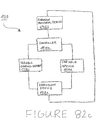
- FIG. 38 a is a flow chart illustration of an exemplary embodiment of a method for processing a tubular member.
- FIG. 38 b is an illustration of the microstructure of an exemplary embodiment of a tubular member prior to thermal processing.
- FIG. 38 c is an illustration of the microstructure of an exemplary embodiment of a tubular member after thermal processing.
- FIG. 39 is a schematic view illustrating an exemplary embodiment of a method for increasing the collapse strength of a tubular assembly.
- FIG. 40 is a perspective view illustrating an exemplary embodiment of an expandable tubular member used in the method of FIG. 39 .
- FIG. 41 a is a perspective view illustrating an exemplary embodiment of the expandable tubular member of FIG. 40 coated with a layer of material according to the method of FIG. 39 .
- FIG. 41 b is a cross sectional view taken along line 41 b in FIG. 41 a illustrating an exemplary embodiment of the expandable tubular member of FIG. 40 coated with a layer of material according to the method of FIG. 39 .
- FIG. 41 c is a perspective view illustrating an exemplary embodiment of the expandable tubular member and layer of FIG. 41 a where the coating layer is plastic according to the method of FIG. 39 .
- FIG. 41 d is a perspective view illustrating an exemplary embodiment of the expandable tubular member and layer of FIG. 41 a where the coating layer is aluminum according to the method of FIG. 39 .
- FIG. 42 is a perspective view illustrating an exemplary embodiment of the expandable tubular member and layer of FIG. 41 a positioned within a preexisting structure according to the method of FIG. 39 .
- FIG. 43 is a perspective view illustrating an exemplary embodiment of the expandable tubular member and layer within the preexisting structure of FIG. 42 with the expandable tubular member being expanded according to the method of FIG. 39 .
- FIG. 44 is a perspective view illustrating an exemplary embodiment of the expandable tubular member and layer within the preexisting structure of FIG. 42 with the expandable tubular member expanded according to the method of FIG. 39 .
- FIG. 45 is a schematic view illustrating an exemplary embodiment of a method for increasing the collapse strength of a tubular assembly.
- FIG. 46 is a perspective view illustrating an exemplary embodiment of a preexisting structure used in the method of FIG. 45 .
- FIG. 47 a is a perspective view illustrating an exemplary embodiment of the preexisting structure of FIG. 46 being coated with a layer of material according to the method of FIG. 45 .
- FIG. 47 b is a cross sectional view taken along line 47 b in FIG. 47 a illustrating an exemplary embodiment of the preexisting structure of FIG. 46 coated with a layer of material according to the method of FIG. 45 .
- FIG. 48 is a perspective view illustrating an exemplary embodiment of an expandable tubular member positioned within the preexisting structure and layer of material of FIG. 47 a according to the method of FIG. 45 .
- FIG. 49 is a perspective view illustrating an exemplary embodiment of the expandable tubular member within the preexisting structure and layer of FIG. 48 with the expandable tubular member being expanded according to the method of FIG. 45 .
- FIG. 50 is a perspective view illustrating an exemplary embodiment of the expandable tubular member within the preexisting structure and layer of FIG. 48 with the expandable tubular member expanded according to the method of FIG. 45 .
- FIG. 51 a is a perspective view illustrating an exemplary embodiment of the expandable tubular member of FIG. 40 coated with multiple layers of material according to the method of FIG. 39 .
- FIG. 51 b is a perspective view illustrating an exemplary embodiment of the preexisting structure of FIG. 46 coated with multiple layers of material according to the method of FIG. 39 .
- FIG. 52 a is a perspective view illustrating an exemplary embodiment of the expandable tubular member of FIG. 40 coated by winding a wire around its circumference according to the method of FIG. 39 .
- FIG. 52 b is a perspective view illustrating an exemplary embodiment of the expandable tubular member of FIG. 40 coated by winding wire around its circumference according to the method of FIG. 39 .
- FIG. 52 c is a cross sectional view taken along line 52 c of FIG. 52 b illustrating an exemplary embodiment of the expandable tubular member of FIG. 40 coated by winding wire around its circumference according to the method of FIG. 39 .
- FIG. 52 d is a cross sectional view illustrating an exemplary embodiment of the expandable tubular member of FIG. 40 coated by winding wire around its circumference according to the method of FIG. 39 after expansion in the preexisting structure of FIG. 42 .
- FIG. 53 is a chart view illustrating an exemplary experimental embodiment of the energy required to expand a plurality of tubular assemblies produced by the methods of FIG. 39 and FIG. 45 .
- FIG. 54 a is a cross sectional view illustrating an exemplary experimental embodiment of a tubular assembly produced by the method of FIG. 39 .
- FIG. 54 b is a cross sectional view illustrating an exemplary experimental embodiment of a tubular assembly produced by the method of FIG. 39 .
- FIG. 54 c is a chart view illustrating an exemplary experimental embodiment of the thickness of the interstitial layer for a plurality of tubular assemblies produced by the method of FIG. 39 .
- FIG. 55 a is a chart view illustrating an exemplary experimental embodiment of the thickness of the interstitial layer for a plurality of tubular assemblies produced by the method of FIG. 39 .
- FIG. 55 b is a chart view illustrating an exemplary experimental embodiment of the thickness of the interstitial layer for a plurality of tubular assemblies produced by the method of FIG. 39 .
- FIG. 56 is a cross sectional view illustrating an exemplary experimental embodiment of a tubular assembly produced by the method of FIG. 39 but omitting the coating with a layer of material.
- FIG. 56 a is a close up cross sectional view illustrating an exemplary experimental embodiment of a tubular assembly produced by the method of FIG. 39 but omitting the coating with a layer of material.
- FIG. 57 a is a graphical view illustrating an exemplary experimental embodiment of the collapse strength for a tubular assembly produced by the method of FIG. 39 but omitting the coating with a layer of material.
- FIG. 57 b is a graphical view illustrating an exemplary experimental embodiment of the thickness of the air gap for a tubular assembly produced by the method of FIG. 39 but omitting the coating with a layer of material.
- FIG. 58 is a graphical view illustrating an exemplary experimental embodiment of the thickness of the air gap and the collapse strength for a tubular assembly produced by the method of FIG. 39 but omitting the coating with a layer of material.
- FIG. 59 is a graphical view illustrating an exemplary experimental embodiment of the thickness of the interstitial layer and the collapse strength for a tubular assembly produced by the method of FIG. 39 .
- FIG. 60 a is a graphical view illustrating an exemplary experimental embodiment of the thickness of the air gap for a tubular assembly produced by the method of FIG. 39 but omitting the coating with a layer of material.
- FIG. 60 b is a graphical view illustrating an exemplary experimental embodiment of the thickness of the interstitial layer for a tubular assembly produced by the method of FIG. 39 .
- FIG. 60 c is a graphical view illustrating an exemplary experimental embodiment of the thickness of the interstitial layer for a tubular assembly produced by the method of FIG. 39 .
- FIG. 61 a is a graphical view illustrating an exemplary experimental embodiment of the wall thickness of an expandable tubular member for a tubular assembly produced by the method of FIG. 39 but omitting the coating with a layer of material.
- FIG. 61 b is a graphical view illustrating an exemplary experimental embodiment of the wall thickness of an expandable tubular member for a tubular assembly produced by the method of FIG. 39 .
- FIG. 61 c is a graphical view illustrating an exemplary experimental embodiment of the wall thickness of an expandable tubular member for a tubular assembly produced by the method of FIG. 39 .
- FIG. 62 a is a graphical view illustrating an exemplary experimental embodiment of the wall thickness of a preexisting structure for a tubular assembly produced by the method of FIG. 39 but omitting the coating with a layer of material.
- FIG. 62 b is a graphical view illustrating an exemplary experimental embodiment of the wall thickness of a preexisting structure for a tubular assembly produced by the method of FIG. 39 .
- FIG. 62 c is a graphical view illustrating an exemplary experimental embodiment of the wall thickness of a preexisting structure for a tubular assembly produced by the method of FIG. 39 .
- FIG. 63 is a graphical view illustrating an exemplary experimental embodiment of the collapse strength for a tubular assembly produced by the method of FIG. 39 .
- FIG. 64 is a flow chart illustrating an exemplary embodiment of a method for increasing the collapse strength of a tubular assembly.
- FIG. 65 is a perspective view illustrating an exemplary embodiment of an expandable tubular member used in the method of FIG. 64 .
- FIG. 66 a is a perspective view illustrating an exemplary embodiment of the expandable tubular member of FIG. 65 coated with a layer of material according to the method of FIG. 64 .
- FIG. 66 b is a cross sectional view taken along line 66 b in FIG. 66 a illustrating an exemplary embodiment of the expandable tubular member of FIG. 65 coated with a layer of material according to the method of FIG. 64 .
- FIG. 67 is a perspective view illustrating an exemplary embodiment of the expandable tubular member and layer of FIG. 66 a positioned within a preexisting structure according to the method of FIG. 64 .
- FIG. 68 is a perspective view illustrating an exemplary embodiment of the expandable tubular member and layer within the preexisting structure of FIG. 67 with the expandable tubular member being expanded according to the method of FIG. 64 .
- FIG. 69 a is a perspective view illustrating an exemplary embodiment of the expandable tubular member and layer within the preexisting structure of FIG. 67 with the expandable tubular member expanded according to the method of FIG. 64 .
- FIG. 69 b is a schematic view illustrating an exemplary embodiment of the expandable tubular member and layer expanded within the preexisting structure of FIG. 69 a with a circumferential tensile force in the preexisting structure.
- FIG. 70 is a cross sectional view illustrating an exemplary embodiment of the expandable tubular member and layer expanded within the preexisting structure of FIG. 69 a with a testing aperture formed in the preexisting structure in order to collapse test the expandable tubular member.
- FIG. 71 is a graph illustrating an exemplary experimental embodiment of a collapse test conducted on the expandable tubular member and the preexisting structure of FIG. 69 a but with an air gap rather than the layer between them.
- FIG. 72 is a graph illustrating an exemplary experimental embodiment of a collapse test conducted on the expandable tubular member and the preexisting structure of FIG. 69 a with a plastic used as the layer between them.
- FIG. 73 is a graph illustrating an exemplary experimental embodiment of a collapse test conducted on the expandable tubular member and the preexisting structure of FIG. 69 a with an aluminum material used as the layer between them.
- FIG. 74 is a graph illustrating an exemplary experimental embodiment of a collapse test conducted on the expandable tubular member and the preexisting structure of FIG. 69 a with an aluminum and zinc material used as the layer between them.
- FIG. 75 is a partial cross sectional view illustrating an exemplary embodiment of an expandable tubular member positioned in a preexisting structure.
- FIG. 76 a is a perspective view illustrating an exemplary embodiment of a tubular member expansion apparatus used with the expandable tubular member of FIG. 75 .
- FIG. 76 b is a side view illustrating an exemplary embodiment of the tubular member expansion apparatus of FIG. 76 a.
- FIG. 76 c is a schematic and perspective view illustrating an exemplary alternative embodiment of the tubular member expansion apparatus of FIGS. 76 a and 76 b.
- FIG. 77 a is a flow chart illustrating an exemplary embodiment of a method for radially expanding and plastically deforming an expandable tubular member.
- FIG. 77 b is a partial cross sectional view illustrating an exemplary embodiment of the tubular member expansion apparatus of FIG. 76 a radially expanding and plastically deforming the expandable tubular member of FIG. 75 .
- FIG. 78 a is a graph illustrating an exemplary experimental embodiment of the tubular member expansion apparatus of FIG. 76 a exhibiting normal expansion characteristics during the radial expansion and plastic deformation of the expandable tubular member of FIG. 75 .
- FIG. 78 b is a graph illustrating an exemplary experimental embodiment of the tubular member expansion apparatus of FIG. 76 a exhibiting normal expansion characteristics during the radial expansion and plastic deformation of the expandable tubular member of FIG. 75 .
- FIG. 79 a is a graph illustrating an exemplary experimental embodiment of the tubular member expansion apparatus of FIG. 76 a exhibiting slip-stick expansion characteristics during the radial expansion and plastic deformation of the expandable tubular member of FIG. 75 .
- FIG. 79 b is a graph illustrating an exemplary experimental embodiment of the tubular member expansion apparatus of FIG. 76 a exhibiting slip-stick expansion characteristics during the radial expansion and plastic deformation of the expandable tubular member of FIG. 75 .
- FIG. 80 a is a graph illustrating an exemplary experimental embodiment of the tubular member expansion apparatus of FIG. 76 a exhibiting jetting expansion characteristics during the radial expansion and plastic deformation of the expandable tubular member of FIG. 75 .
- FIG. 80 b is a graph illustrating an exemplary experimental embodiment of the tubular member expansion apparatus of FIG. 76 a exhibiting jetting expansion characteristics during the radial expansion and plastic deformation of the expandable tubular member of FIG. 75 .
- FIG. 81 is a partial cross sectional view illustrating an exemplary embodiment of an expandable tubular member positioned in a preexisting structure.
- FIG. 82 a is a side view illustrating an exemplary embodiment of a tubular member expansion apparatus used with the expandable tubular member of FIG. 81 .
- FIG. 82 b is a side view illustrating an exemplary alternative embodiment of the tubular member expansion apparatus of FIG. 82 a.
- FIG. 82 c is a schematic view illustrating an exemplary alternative embodiment of the tubular member expansion apparatus of FIG. 82 a.
- FIG. 83 a is a flow chart illustrating an exemplary embodiment of a method for radially expanding and plastically deforming an expandable tubular member.
- FIG. 83 b is a partial cross sectional view illustrating an exemplary embodiment of the tubular member expansion apparatus of FIG. 82 radially expanding and plastically deforming the expandable tubular member of FIG. 81 .
- FIG. 84 is a partial cross sectional view illustrating an exemplary embodiment of an expandable tubular member positioned in a preexisting structure.
- FIG. 85 a is a side view illustrating an exemplary embodiment of a tubular member expansion apparatus used with the expandable tubular member of FIG. 84 .
- FIG. 85 b is a partial cross sectional view illustrating an exemplary embodiment of the tubular member expansion apparatus of FIG. 85 a.
- FIG. 86 a is a flow chart illustrating an exemplary embodiment of a method for radially expanding and plastically deforming an expandable tubular member.
- FIG. 86 b is a partial cross sectional view illustrating an exemplary embodiment of the tubular member expansion apparatus of FIG. 85 a radially expanding and plastically deforming the expandable tubular member of FIG. 84 .
- FIG. 87 is a partial cross sectional view illustrating an exemplary embodiment of an expandable tubular member positioned in a preexisting structure.
- FIG. 88 a is a side view illustrating an exemplary embodiment of a tubular member expansion apparatus used with the expandable tubular member of FIG. 87 .
- FIG. 88 b is a partial cross sectional view illustrating an exemplary embodiment of the tubular member expansion apparatus of FIG. 88 a.
- FIG. 89 a is a flow chart illustrating an exemplary embodiment of a method for radially expanding and plastically deforming an expandable tubular member.
- FIG. 89 b is a partial cross sectional view illustrating an exemplary embodiment of the tubular member expansion apparatus of FIG. 88 a radially expanding and plastically deforming the expandable tubular member of FIG. 87 .
- FIG. 90 is a perspective view illustrating an exemplary embodiment of an expandable tubular member.
- FIG. 91 is a partial cross sectional view illustrating an exemplary embodiment of a formation used with the expandable tubular member of FIG. 90 .
- FIG. 92 a is a flow chart illustrating an exemplary embodiment of a method for radially expanding and plastically deforming an expandable tubular member.
- FIG. 92 b is a perspective view illustrating an exemplary embodiment of the expandable tubular member of FIG. 90 coated with an elastomer layer.
- FIG. 92 c is a partial cross sectional view illustrating an exemplary embodiment of the expandable tubular member of FIG. 92 b positioned in the formation of FIG. 91 .
- FIG. 92 d is a partial cross sectional view illustrating the expandable tubular member of FIG. 92 b expanded in the formation of FIG. 91 prior to formation rebound.
- FIG. 92 e is a partial cross sectional view illustrating the expandable tubular member of FIG. 92 b expanded in the formation of FIG. 91 after formation rebound.
- FIG. 92 f is a partial cross sectional view illustrating an exemplary embodiment of the expandable tubular member of FIG. 92 b being expanded in the formation of FIG. 91 .
- FIG. 93 is a schematic fragmentary cross-sectional view illustrating an exemplary embodiment along a plane along and through the central axis of a tubular member that is tested to failure with axial opposed forces.
- FIG. 94 is a stress-strain curve illustrating an exemplary embodiment representing values for stress and strain that may be plotted for solid specimen sample.
- FIG. 95 is a schematically view illustrating an exemplary embodiment of a stress strain curve representing values from a test on a tubular member according to an illustrative example of one aspect of the invention.
- an exemplary embodiment of an expandable tubular assembly 10 includes a first expandable tubular member 12 coupled to a second expandable tubular member 14 .
- the ends of the first and second expandable tubular members, 12 and 14 are coupled using, for example, a conventional mechanical coupling, a welded connection, a brazed connection, a threaded connection, and/or an interference fit connection.
- the first expandable tubular member 12 has a plastic yield point YP 1
- the second expandable tubular member 14 has a plastic yield point YP 2 .
- the expandable tubular assembly 10 is positioned within a preexisting structure such as, for example, a wellbore 16 that traverses a subterranean formation 18 .
- an expansion device 20 may then be positioned within the second expandable tubular member 14 .
- the expansion device 20 may include, for example, one or more of the following conventional expansion devices: a) an expansion cone; b) a rotary expansion device; c) a hydroforming expansion device; d) an impulsive force expansion device; d) any one of the expansion devices commercially available from, or disclosed in any of the published patent applications or issued patents, of Weatherford International, Baker Hughes, Halliburton Energy Services, Shell Oil Co., Schlumberger, and/or Enventure Global Technology L.L.C.
- the expansion device 20 is positioned within the second expandable tubular member 14 before, during, or after the placement of the expandable tubular assembly 10 within the preexisting structure 16 .
- the expansion device 20 may then be operated to radially expand and plastically deform at least a portion of the second expandable tubular member 14 to form a bell-shaped section.
- the expansion device 20 may then be operated to radially expand and plastically deform the remaining portion of the second expandable tubular member 14 and at least a portion of the first expandable tubular member 12 .
- At least a portion of at least a portion of at least one of the first and second expandable tubular members, 12 and 14 are radially expanded into intimate contact with the interior surface of the preexisting structure 16 .
- the plastic yield point YP 1 is greater than the plastic yield point YP 2 .
- the amount of power and/or energy required to radially expand the second expandable tubular member 14 is less than the amount of power and/or energy required to radially expand the first expandable tubular member 12 .
- the first expandable tubular member 12 and/or the second expandable tubular member 14 have a ductility D PE and a yield strength YS PE prior to radial expansion and plastic deformation, and a ductility D AE and a yield strength YS AE after radial expansion and plastic deformation.
- D PE is greater than D AE
- YS AE is greater than YS PE .
- the amount of power and/or energy required to radially expand each unit length of the first and/or second expandable tubular members, 12 and 14 is reduced. Furthermore, because the YS AE is greater than YS PE , the collapse strength of the first expandable tubular member 12 and/or the second expandable tubular member 14 is increased after the radial expansion and plastic deformation process.
- At least a portion of the second expandable tubular member 14 has an inside diameter that is greater than at least the inside diameter of the first expandable tubular member 12 .
- a bell-shaped section is formed using at least a portion of the second expandable tubular member 14 .
- Another expandable tubular assembly 22 that includes a first expandable tubular member 24 and a second expandable tubular member 26 may then be positioned in overlapping relation to the first expandable tubular assembly 10 and radially expanded and plastically deformed using the methods described above with reference to FIGS. 1-4 .
- At least a portion of the second expandable tubular member 26 has an inside diameter that is greater than at least the inside diameter of the first expandable tubular member 24 .
- a bell-shaped section is formed using at least a portion of the second expandable tubular member 26 .
- a mono-diameter tubular assembly is formed that defines an internal passage 28 having a substantially constant cross-sectional area and/or inside diameter.
- an exemplary embodiment of an expandable tubular assembly 100 includes a first expandable tubular member 102 coupled to a tubular coupling 104 .
- the tubular coupling 104 is coupled to a tubular coupling 106 .
- the tubular coupling 106 is coupled to a second expandable tubular member 108 .
- the tubular couplings, 104 and 106 provide a tubular coupling assembly for coupling the first and second expandable tubular members, 102 and 108 , together that may include, for example, a conventional mechanical coupling, a welded connection, a brazed connection, a threaded connection, and/or an interference fit connection.
- the first and second expandable tubular members 12 have a plastic yield point YP 1
- the tubular couplings, 104 and 106 have a plastic yield point YP 2
- the expandable tubular assembly 100 is positioned within a preexisting structure such as, for example, a wellbore 110 that traverses a subterranean formation 112 .
- an expansion device 114 may then be positioned within the second expandable tubular member 108 .
- the expansion device 114 may include, for example, one or more of the following conventional expansion devices: a) an expansion cone; b) a rotary expansion device; c) a hydroforming expansion device; d) an impulsive force expansion device; d) any one of the expansion devices commercially available from, or disclosed in any of the published patent applications or issued patents, of Weatherford International, Baker Hughes, Halliburton Energy Services, Shell Oil Co., Schlumberger, and/or Enventure Global Technology L.L.C.
- the expansion device 114 is positioned within the second expandable tubular member 108 before, during, or after the placement of the expandable tubular assembly 100 within the preexisting structure 110 .
- the expansion device 114 may then be operated to radially expand and plastically deform at least a portion of the second expandable tubular member 108 to form a bell-shaped section.
- the expansion device 114 may then be operated to radially expand and plastically deform the remaining portion of the second expandable tubular member 108 , the tubular couplings, 104 and 106 , and at least a portion of the first expandable tubular member 102 .
- At least a portion of at least a portion of at least one of the first and second expandable tubular members, 102 and 108 are radially expanded into intimate contact with the interior surface of the preexisting structure 110 .
- the plastic yield point YP 1 is less than the plastic yield point YP 2 .
- the amount of power and/or energy required to radially expand each unit length of the first and second expandable tubular members, 102 and 108 is less than the amount of power and/or energy required to radially expand each unit length of the tubular couplings, 104 and 106 .
- the first expandable tubular member 12 and/or the second expandable tubular member 14 have a ductility D PE and a yield strength YS PE prior to radial expansion and plastic deformation, and a ductility D AE and a yield strength YS AE after radial expansion and plastic deformation.
- D PE is greater than D AE
- YS AE is greater than YS PE .
- the amount of power and/or energy required to radially expand each unit length of the first and/or second expandable tubular members, 12 and 14 is reduced. Furthermore, because the YS AE is greater than YS PE , the collapse strength of the first expandable tubular member 12 and/or the second expandable tubular member 14 is increased after the radial expansion and plastic deformation process.
- an exemplary embodiment of an expandable tubular assembly 200 includes a first expandable tubular member 202 coupled to a second expandable tubular member 204 that defines radial openings 204 a , 204 b , 204 c , and 204 d .
- the ends of the first and second expandable tubular members, 202 and 204 are coupled using, for example, a conventional mechanical coupling, a welded connection, a brazed connection, a threaded connection, and/or an interference fit connection.
- one or more of the radial openings, 204 a , 204 b , 204 c , and 204 d have circular, oval, square, and/or irregular cross sections and/or include portions that extend to and interrupt either end of the second expandable tubular member 204 .
- the expandable tubular assembly 200 is positioned within a preexisting structure such as, for example, a wellbore 206 that traverses a subterranean formation 208 .
- an expansion device 210 may then be positioned within the second expandable tubular member 204 .
- the expansion device 210 may include, for example, one or more of the following conventional expansion devices: a) an expansion cone; b) a rotary expansion device; c) a hydroforming expansion device; d) an impulsive force expansion device; d) any one of the expansion devices commercially available from, or disclosed in any of the published patent applications or issued patents, of Weatherford International, Baker Hughes, Halliburton Energy Services, Shell Oil Co., Schlumberger, and/or Enventure Global Technology L.L.C.
- the expansion device 210 is positioned within the second expandable tubular member 204 before, during, or after the placement of the expandable tubular assembly 200 within the preexisting structure 206 .
- the expansion device 210 may then be operated to radially expand and plastically deform at least a portion of the second expandable tubular member 204 to form a bell-shaped section.
- the expansion device 20 may then be operated to radially expand and plastically deform the remaining portion of the second expandable tubular member 204 and at least a portion of the first expandable tubular member 202 .
- WT f final wall thickness of the expandable tubular member following the radial expansion and plastic deformation of the expandable tubular member
- WT i initial wall thickness of the expandable tubular member prior to the radial expansion and plastic deformation of the expandable tubular member
- D f final inside diameter of the expandable tubular member following the radial expansion and plastic deformation of the expandable tubular member
- D i initial inside diameter of the expandable tubular member prior to the radial expansion and plastic deformation of the expandable tubular member.
- the anisotropy ratio AR for the first and/or second expandable tubular members, 204 and 204 is greater than 1.
- the second expandable tubular member 204 had an anisotropy ratio AR greater than 1, and the radial expansion and plastic deformation of the second expandable tubular member did not result in any of the openings, 204 a , 204 b , 204 c , and 204 d , splitting or otherwise fracturing the remaining portions of the second expandable tubular member. This was an unexpected result.
- one or more of the expandable tubular members, 12 , 14 , 24 , 26 , 102 , 104 , 106 , 108 , 202 and/or 204 are processed using a method 300 in which a tubular member in an initial state is thermo-mechanically processed in step 302 .
- the thermo-mechanical processing 302 includes one or more heat treating and/or mechanical forming processes.
- the tubular member is transformed to an intermediate state.
- the tubular member is then further thermo-mechanically processed in step 304 .
- the thermo-mechanical processing 304 includes one or more heat treating and/or mechanical forming processes.
- the tubular member is transformed to a final state.
- the tubular member has a ductility D PE and a yield strength YS PE prior to the final thermo-mechanical processing in step 304 , and a ductility D AE and a yield strength YS AE after final thermo-mechanical processing.
- D PE is greater than D AE
- YS AE is greater than YS PE .
- the amount of energy and/or power required to transform the tubular member, using mechanical forming processes, during the final thermo-mechanical processing in step 304 is reduced.
- the YS AE is greater than YS PE , the collapse strength of the tubular member is increased after the final thermo-mechanical processing in step 304 .
- one or more of the expandable tubular members, 12 , 14 , 24 , 26 , 102 , 104 , 106 , 108 , 202 and/or 204 have the following characteristics:
- one or more of the line expandable tubular members, 12 , 14 , 24 , 26 , 102 , 104 , 106 , 108 , 202 and/or 204 are characterized by an expandability coefficient f:
- the anisotropy coefficient for one or more of the expandable tubular members, 12 , 14 , 24 , 26 , 102 , 104 , 106 , 108 , 202 and/or 204 is greater than 1.
- the strain hardening exponent for one or more of the expandable tubular members, 12 , 14 , 24 , 26 , 102 , 104 , 106 , 108 , 202 and/or 204 is greater than 0.12.
- the expandability coefficient for one or more of the expandable tubular members, 12 , 14 , 24 , 26 , 102 , 104 , 106 , 108 , 202 and/or 204 is greater than 0.12.
- a tubular member having a higher expandability coefficient requires less power and/or energy to radially expand and plastically deform each unit length than a tubular member having a lower expandability coefficient. In an exemplary embodiment, a tubular member having a higher expandability coefficient requires less power and/or energy per unit length to radially expand and plastically deform than a tubular member having a lower expandability coefficient.
- one or more of the expandable tubular members, 12 , 14 , 24 , 26 , 102 , 104 , 106 , 108 , 202 and/or 204 are steel alloys having one of the following compositions:
- a sample of an expandable tubular member composed of Alloy A exhibited a yield point before radial expansion and plastic deformation YP BE , a yield point after radial expansion and plastic deformation of about 16% YP AE16% , and a yield point after radial expansion and plastic deformation of about 24% YP AE24% .
- YP AE24% >YP AE16% >YP BE .
- the ductility of the sample of the expandable tubular member composed of Alloy A also exhibited a higher ductility prior to radial expansion and plastic deformation than after radial expansion and plastic deformation.
- a sample of an expandable tubular member composed of Alloy A exhibited the following tensile characteristics before and after radial expansion and plastic deformation:
- a sample of an expandable tubular member composed of Alloy B exhibited a yield point before radial expansion and plastic deformation YP BE , a yield point after radial expansion and plastic deformation of about 16% YP AE16% , and a yield point after radial expansion and plastic deformation of about 24% YP AE24% .
- YP AE24% >YP AE16% >YP BE .
- the ductility of the sample of the expandable tubular member composed of Alloy B also exhibited a higher ductility prior to radial expansion and plastic deformation than after radial expansion and plastic deformation.
- a sample of an expandable tubular member composed of Alloy B exhibited the following tensile characteristics before and after radial expansion and plastic deformation:
- samples of expandable tubulars composed of Alloys A, B, C, and D exhibited the following tensile characteristics prior to radial expansion and plastic deformation:
- one or more of the expandable tubular members, 12 , 14 , 24 , 26 , 102 , 104 , 106 , 108 , 202 and/or 204 have a strain hardening exponent greater than 0.12, and a yield ratio is less than 0.85.
- Mn manganese percentage by weight
- V vanadium percentage by weight
- g. Nb niobium percentage by weight
- Ni nickel percentage by weight
- the carbon equivalent value C e for tubular members having a carbon content less than or equal to 0.12% (by weight), for one or more of the expandable tubular members, 12 , 14 , 24 , 26 , 102 , 104 , 106 , 108 , 202 and/or 204 is less than 0.21.
- Si silicon percentage by weight
- Ni nickel percentage by weight
- V vanadium percentage by weight
- the carbon equivalent value C e for tubular members having greater than 0.12% carbon content (by weight), for one or more of the expandable tubular members, 12 , 14 , 24 , 26 , 102 , 104 , 106 , 108 , 202 and/or 204 is less than 0.36.
- a first tubular member 2210 includes an internally threaded connection 2212 at an end portion 2214 .
- a first end of a tubular sleeve 2216 that includes an internal flange 2218 having a tapered portion 2220 , and a second end that includes a tapered portion 2222 is then mounted upon and receives the end portion 2214 of the first tubular member 2210 .
- the end portion 2214 of the first tubular member 2210 abuts one side of the internal flange 2218 of the tubular sleeve 2216 , and the internal diameter of the internal flange 2218 of the tubular sleeve 2216 is substantially equal to or greater than the maximum internal diameter of the internally threaded connection 2212 of the end portion 2214 of the first tubular member 2210 .
- An externally threaded connection 2224 of an end portion 2226 of a second tubular member 2228 having an annular recess 2230 is then positioned within the tubular sleeve 2216 and threadably coupled to the internally threaded connection 2212 of the end portion 2214 of the first tubular member 2210 .
- the internal flange 2218 of the tubular sleeve 2216 mates with and is received within the annular recess 2230 of the end portion 2226 of the second tubular member 2228 .
- the tubular sleeve 2216 is coupled to and surrounds the external surfaces of the first and second tubular members, 2210 and 2228 .
- the internally threaded connection 2212 of the end portion 2214 of the first tubular member 2210 is a box connection
- the externally threaded connection 2224 of the end portion 2226 of the second tubular member 2228 is a pin connection.
- the internal diameter of the tubular sleeve 2216 is at least approximately 0.020′′ greater than the outside diameters of the first and second tubular members, 2210 and 2228 . In this manner, during the threaded coupling of the first and second tubular members, 2210 and 2228 , fluidic materials within the first and second tubular members may be vented from the tubular members.
- first and second tubular members, 2210 and 2228 , and the tubular sleeve 2216 may be positioned within another structure 2232 such as, for example, a cased or uncased wellbore, and radially expanded and plastically deformed, for example, by displacing and/or rotating a conventional expansion device 2234 within and/or through the interiors of the first and second tubular members.
- the tapered portions, 2220 and 2222 , of the tubular sleeve 2216 facilitate the insertion and movement of the first and second tubular members within and through the structure 2232 , and the movement of the expansion device 2234 through the interiors of the first and second tubular members, 2210 and 2228 , may be, for example, from top to bottom or from bottom to top.
- the tubular sleeve 2216 is also radially expanded and plastically deformed. As a result, the tubular sleeve 2216 may be maintained in circumferential tension and the end portions, 2214 and 2226 , of the first and second tubular members, 2210 and 2228 , may be maintained in circumferential compression.
- Sleeve 2216 increases the axial compression loading of the connection between tubular members 2210 and 2228 before and after expansion by the expansion device 2234 .
- Sleeve 2216 may, for example, be secured to tubular members 2210 and 2228 by a heat shrink fit.
- first and second tubular members, 2210 and 2228 are radially expanded and plastically deformed using other conventional methods for radially expanding and plastically deforming tubular members such as, for example, internal pressurization, hydroforming, and/or roller expansion devices and/or any one or combination of the conventional commercially available expansion products and services available from Baker Hughes, Weatherford International, and/or Enventure Global Technology L.L.C.
- tubular sleeve 2216 during (a) the coupling of the first tubular member 2210 to the second tubular member 2228 , (b) the placement of the first and second tubular members in the structure 2232 , and (c) the radial expansion and plastic deformation of the first and second tubular members provides a number of significant benefits.
- the tubular sleeve 2216 protects the exterior surfaces of the end portions, 2214 and 2226 , of the first and second tubular members, 2210 and 2228 , during handling and insertion of the tubular members within the structure 2232 .
- tubular sleeve 2216 provides an alignment guide that facilitates the insertion and threaded coupling of the second tubular member 2228 to the first tubular member 2210 . In this manner, misalignment that could result in damage to the threaded connections, 2212 and 2224 , of the first and second tubular members, 2210 and 2228 , may be avoided.
- the tubular sleeve 2216 provides an indication of to what degree the first and second tubular members are threadably coupled. For example, if the tubular sleeve 2216 can be easily rotated, that would indicate that the first and second tubular members, 2210 and 2228 , are not fully threadably coupled and in intimate contact with the internal flange 2218 of the tubular sleeve. Furthermore, the tubular sleeve 2216 may prevent crack propagation during the radial expansion and plastic deformation of the first and second tubular members, 2210 and 2228 .
- the tubular sleeve 2216 may provide a fluid tight metal-to-metal seal between interior surface of the tubular sleeve 2216 and the exterior surfaces of the end portions, 2214 and 2226 , of the first and second tubular members.
- tubular sleeve 2216 may be maintained in circumferential tension and the end portions, 2214 and 2226 , of the first and second tubular members, 2210 and 2228 , may be maintained in circumferential compression, axial loads and/or torque loads may be transmitted through the tubular sleeve.
- one or more portions of the first and second tubular members, 2210 and 2228 , and the tubular sleeve 2216 have one or more of the material properties of one or more of the tubular members 12 , 14 , 24 , 26 , 102 , 104 , 106 , 108 , 202 and/or 204 .
- a first tubular member 210 includes an internally threaded connection 2312 at an end portion 2314 .
- a first end of a tubular sleeve 2316 includes an internal flange 2318 and a tapered portion 2320 .
- a second end of the sleeve 2316 includes an internal flange 2321 and a tapered portion 2322 .
- An externally threaded connection 2324 of an end portion 2326 of a second tubular member 2328 having an annular recess 2330 is then positioned within the tubular sleeve 2316 and threadably coupled to the internally threaded connection 2312 of the end portion 2314 of the first tubular member 2310 .
- the internal flange 2318 of the sleeve 2316 mates with and is received within the annular recess 2330 .
- the first tubular member 2310 includes a recess 2331 .
- the internal flange 2321 mates with and is received within the annular recess 2331 .
- the sleeve 2316 is coupled to and surrounds the external surfaces of the first and second tubular members 2310 and 2328 .
- the internally threaded connection 2312 of the end portion 2314 of the first tubular member 2310 is a box connection
- the externally threaded connection 2324 of the end portion 2326 of the second tubular member 2328 is a pin connection.
- the internal diameter of the tubular sleeve 2316 is at least approximately 0.020′′ greater than the outside diameters of the first and second tubular members 2310 and 2328 . In this manner, during the threaded coupling of the first and second tubular members 2310 and 2328 , fluidic materials within the first and second tubular members may be vented from the tubular members.
- the first and second tubular members 2310 and 2328 , and the tubular sleeve 2316 may then be positioned within another structure 2332 such as, for example, a wellbore, and radially expanded and plastically deformed, for example, by displacing and/or rotating an expansion device 2334 through and/or within the interiors of the first and second tubular members.
- the tapered portions 2320 and 2322 , of the tubular sleeve 2316 facilitates the insertion and movement of the first and second tubular members within and through the structure 2332 , and the displacement of the expansion device 2334 through the interiors of the first and second tubular members 2310 and 2328 , may be from top to bottom or from bottom to top.
- the tubular sleeve 2316 is also radially expanded and plastically deformed.
- the tubular sleeve 2316 may be maintained in circumferential tension and the end portions 2314 and 2326 , of the first and second tubular members 2310 and 2328 , may be maintained in circumferential compression.
- Sleeve 2316 increases the axial tension loading of the connection between tubular members 2310 and 2328 before and after expansion by the expansion device 2334 .
- Sleeve 2316 may be secured to tubular members 2310 and 2328 by a heat shrink fit.
- one or more portions of the first and second tubular members, 2310 and 2328 , and the tubular sleeve 2316 have one or more of the material properties of one or more of the tubular members 12 , 14 , 24 , 26 , 102 , 104 , 106 , 108 , 202 and/or 204 .
- a first tubular member 2410 includes an internally threaded connection 2412 at an end portion 2414 .
- a first end of a tubular sleeve 2416 includes an internal flange 2418 and a tapered portion 2420 .
- a second end of the sleeve 2416 includes an internal flange 2421 and a tapered portion 2422 .
- An externally threaded connection 2424 of an end portion 2426 of a second tubular member 2428 having an annular recess 2430 is then positioned within the tubular sleeve 2416 and threadably coupled to the internally threaded connection 2412 of the end portion 2414 of the first tubular member 2410 .
- the internal flange 2418 of the sleeve 2416 mates with and is received within the annular recess 2430 .
- the first tubular member 2410 includes a recess 2431 .
- the internal flange 2421 mates with and is received within the annular recess 2431 .
- the sleeve 2416 is coupled to and surrounds the external surfaces of the first and second tubular members 2410 and 2428 .
- the internally threaded connection 2412 of the end portion 2414 of the first tubular member 2410 is a box connection
- the externally threaded connection 2424 of the end portion 2426 of the second tubular member 2428 is a pin connection.
- the internal diameter of the tubular sleeve 2416 is at least approximately 0.020′′ greater than the outside diameters of the first and second tubular members 2410 and 2428 . In this manner, during the threaded coupling of the first and second tubular members 2410 and 2428 , fluidic materials within the first and second tubular members may be vented from the tubular members.
- first and second tubular members 2410 and 2428 , and the tubular sleeve 2416 may then be positioned within another structure 2432 such as, for example, a wellbore, and radially expanded and plastically deformed, for example, by displacing and/or rotating an expansion device 2434 through and/or within the interiors of the first and second tubular members.
- the tapered portions 2420 and 2422 , of the tubular sleeve 2416 facilitate the insertion and movement of the first and second tubular members within and through the structure 2432 , and the displacement of the expansion device 2434 through the interiors of the first and second tubular members, 2410 and 2428 , may be from top to bottom or from bottom to top.
- the tubular sleeve 2416 is also radially expanded and plastically deformed.
- the tubular sleeve 2416 may be maintained in circumferential tension and the end portions, 2414 and 2426 , of the first and second tubular members, 2410 and 2428 , may be maintained in circumferential compression.
- the sleeve 2416 increases the axial compression and tension loading of the connection between tubular members 2410 and 2428 before and after expansion by expansion device 2424 .
- Sleeve 2416 may be secured to tubular members 2410 and 2428 by a heat shrink fit.
- one or more portions of the first and second tubular members, 2410 and 2428 , and the tubular sleeve 2416 have one or more of the material properties of one or more of the tubular members 12 , 14 , 24 , 26 , 102 , 104 , 106 , 108 , 202 and/or 204 .
- a first tubular member 2510 includes an internally threaded connection 2512 at an end portion 2514 .
- a first end of a tubular sleeve 2516 includes an internal flange 2518 and a relief 2520 .
- a second end of the sleeve 2516 includes an internal flange 2521 and a relief 2522 .
- An externally threaded connection 2524 of an end portion 2526 of a second tubular member 2528 having an annular recess 2530 is then positioned within the tubular sleeve 2516 and threadably coupled to the internally threaded connection 2512 of the end portion 2514 of the first tubular member 2510 .
- the internal flange 2518 of the sleeve 2516 mates with and is received within the annular recess 2530 .
- the first tubular member 2510 includes a recess 2531 .
- the internal flange 2521 mates with and is received within the annular recess 2531 .
- the sleeve 2516 is coupled to and surrounds the external surfaces of the first and second tubular members 2510 and 2528 .
- the internally threaded connection 2512 of the end portion 2514 of the first tubular member 2510 is a box connection
- the externally threaded connection 2524 of the end portion 2526 of the second tubular member 2528 is a pin connection.
- the internal diameter of the tubular sleeve 2516 is at least approximately 0.020′′ greater than the outside diameters of the first and second tubular members 2510 and 2528 . In this manner, during the threaded coupling of the first and second tubular members 2510 and 2528 , fluidic materials within the first and second tubular members may be vented from the tubular members.
- the first and second tubular members 2510 and 2528 , and the tubular sleeve 2516 may then be positioned within another structure 2532 such as, for example, a wellbore, and radially expanded and plastically deformed, for example, by displacing and/or rotating an expansion device 2534 through and/or within the interiors of the first and second tubular members.
- the reliefs 2520 and 2522 are each filled with a sacrificial material 2540 including a tapered surface 2542 and 2544 , respectively.
- the material 2540 may be a metal or a synthetic, and is provided to facilitate the insertion and movement of the first and second tubular members 2510 and 2528 , through the structure 2532 .
- the displacement of the expansion device 2534 through the interiors of the first and second tubular members 2510 and 2528 may, for example, be from top to bottom or from bottom to top.
- the tubular sleeve 2516 is also radially expanded and plastically deformed.
- the tubular sleeve 2516 may be maintained in circumferential tension and the end portions 2514 and 2526 , of the first and second tubular members, 2510 and 2528 , may be maintained in circumferential compression.
- sacrificial material 2540 provided on sleeve 2516 , avoids stress risers on the sleeve 2516 and the tubular member 2510 .
- the tapered surfaces 2542 and 2544 are intended to wear or even become damaged, thus incurring such wear or damage which would otherwise be borne by sleeve 2516 .
- Sleeve 2516 may be secured to tubular members 2510 and 2528 by a heat shrink fit.
- one or more portions of the first and second tubular members, 2510 and 2528 , and the tubular sleeve 2516 have one or more of the material properties of one or more of the tubular members 12 , 14 , 24 , 26 , 102 , 104 , 106 , 108 , 202 and/or 204 .
- a first tubular member 2610 includes an internally threaded connection 2612 at an end portion 2614 .
- a first end of a tubular sleeve 2616 includes an internal flange 2618 and a tapered portion 2620 .
- a second end of the sleeve 2616 includes an internal flange 2621 and a tapered portion 2622 .
- An externally threaded connection 2624 of an end portion 2626 of a second tubular member 2628 having an annular recess 2630 is then positioned within the tubular sleeve 2616 and threadably coupled to the internally threaded connection 2612 of the end portion 2614 of the first tubular member 2610 .
- the internal flange 2618 of the sleeve 2616 mates with and is received within the annular recess 2630 .
- the first tubular member 2610 includes a recess 2631 .
- the internal flange 2621 mates with and is received within the annular recess 2631 .
- the sleeve 2616 is coupled to and surrounds the external surfaces of the first and second tubular members 2610 and 2628 .
- the internally threaded connection 2612 of the end portion 2614 of the first tubular member 2610 is a box connection
- the externally threaded connection 2624 of the end portion 2626 of the second tubular member 2628 is a pin connection.
- the internal diameter of the tubular sleeve 2616 is at least approximately 0.020′′ greater than the outside diameters of the first and second tubular members 2610 and 2628 . In this manner, during the threaded coupling of the first and second tubular members 2610 and 2628 , fluidic materials within the first and second tubular members may be vented from the tubular members.
- first and second tubular members 2610 and 2628 , and the tubular sleeve 2616 may then be positioned within another structure 2632 such as, for example, a wellbore, and radially expanded and plastically deformed, for example, by displacing and/or rotating an expansion device 2634 through and/or within the interiors of the first and second tubular members.
- the tapered portions 2620 and 2622 , of the tubular sleeve 2616 facilitates the insertion and movement of the first and second tubular members within and through the structure 2632 , and the displacement of the expansion device 2634 through the interiors of the first and second tubular members 2610 and 2628 , may, for example, be from top to bottom or from bottom to top.
- the tubular sleeve 2616 is also radially expanded and plastically deformed.
- the tubular sleeve 2616 may be maintained in circumferential tension and the end portions 2614 and 2626 , of the first and second tubular members 2610 and 2628 , may be maintained in circumferential compression.
- Sleeve 2616 is covered by a thin walled cylinder of sacrificial material 2640 . Spaces 2623 and 2624 , adjacent tapered portions 2620 and 2622 , respectively, are also filled with an excess of the sacrificial material 2640 .
- the material may be a metal or a synthetic, and is provided to facilitate the insertion and movement of the first and second tubular members 2610 and 2628 , through the structure 2632 .
- sacrificial material 2640 provided on sleeve 2616 , avoids stress risers on the sleeve 2616 and the tubular member 2610 .
- the excess of the sacrificial material 2640 adjacent tapered portions 2620 and 2622 are intended to wear or even become damaged, thus incurring such wear or damage which would otherwise be borne by sleeve 2616 .
- Sleeve 2616 may be secured to tubular members 2610 and 2628 by a heat shrink fit.
- one or more portions of the first and second tubular members, 2610 and 2628 , and the tubular sleeve 2616 have one or more of the material properties of one or more of the tubular members 12 , 14 , 24 , 26 , 102 , 104 , 106 , 108 , 202 and/or 204 .
- a first tubular member 2710 includes an internally threaded connection 2712 at an end portion 2714 .
- a first end of a tubular sleeve 2716 includes an internal flange 2718 and a tapered portion 2720 .
- a second end of the sleeve 2716 includes an internal flange 2721 and a tapered portion 2722 .
- An externally threaded connection 2724 of an end portion 2726 of a second tubular member 2728 having an annular recess 2730 is then positioned within the tubular sleeve 2716 and threadably coupled to the internally threaded connection 2712 of the end portion 2714 of the first tubular member 2710 .
- the internal flange 2718 of the sleeve 2716 mates with and is received within the annular recess 2730 .
- the first tubular member 2710 includes a recess 2731 .
- the internal flange 2721 mates with and is received within the annular recess 2731 .
- the sleeve 2716 is coupled to and surrounds the external surfaces of the first and second tubular members 2710 and 2728 .
- the internally threaded connection 2712 of the end portion 2714 of the first tubular member 2710 is a box connection
- the externally threaded connection 2724 of the end portion 2726 of the second tubular member 2728 is a pin connection.
- the internal diameter of the tubular sleeve 2716 is at least approximately 0.020′′ greater than the outside diameters of the first and second tubular members 2710 and 2728 . In this manner, during the threaded coupling of the first and second tubular members 2710 and 2728 , fluidic materials within the first and second tubular members may be vented from the tubular members.
- first and second tubular members 2710 and 2728 , and the tubular sleeve 2716 may then be positioned within another structure 2732 such as, for example, a wellbore, and radially expanded and plastically deformed, for example, by displacing and/or rotating an expansion device 2734 through and/or within the interiors of the first and second tubular members.
- the tapered portions 2720 and 2722 , of the tubular sleeve 2716 facilitates the insertion and movement of the first and second tubular members within and through the structure 2732 , and the displacement of the expansion device 2734 through the interiors of the first and second tubular members 2710 and 2728 , may be from top to bottom or from bottom to top.
- the tubular sleeve 2716 is also radially expanded and plastically deformed.
- the tubular sleeve 2716 may be maintained in circumferential tension and the end portions 2714 and 2726 , of the first and second tubular members 2710 and 2728 , may be maintained in circumferential compression.
- Sleeve 2716 has a variable thickness due to one or more reduced thickness portions 2790 and/or increased thickness portions 2792 .
- Varying the thickness of sleeve 2716 provides the ability to control or induce stresses at selected positions along the length of sleeve 2716 and the end portions 2724 and 2726 .
- Sleeve 2716 may be secured to tubular members 2710 and 2728 by a heat shrink fit.
- one or more portions of the first and second tubular members, 2710 and 2728 , and the tubular sleeve 2716 have one or more of the material properties of one or more of the tubular members 12 , 14 , 24 , 26 , 102 , 104 , 106 , 108 , 202 and/or 204 .
- the same result described above with reference to FIG. 27 may be achieved by adding a member 2740 which may be coiled onto the grooves 2739 formed in sleeve 2716 , thus varying the thickness along the length of sleeve 2716 .
- a first tubular member 2910 includes an internally threaded connection 2912 and an internal annular recess 2914 at an end portion 2916 .
- a first end of a tubular sleeve 2918 includes an internal flange 2920 , and a second end of the sleeve 2916 mates with and receives the end portion 2916 of the first tubular member 2910 .
- An externally threaded connection 2922 of an end portion 2924 of a second tubular member 2926 having an annular recess 2928 is then positioned within the tubular sleeve 2918 and threadably coupled to the internally threaded connection 2912 of the end portion 2916 of the first tubular member 2910 .
- the internal flange 2920 of the sleeve 2918 mates with and is received within the annular recess 2928 .
- a sealing element 2930 is received within the internal annular recess 2914 of the end portion 2916 of the first tubular member 2910 .
- the internally threaded connection 2912 of the end portion 2916 of the first tubular member 2910 is a box connection
- the externally threaded connection 2922 of the end portion 2924 of the second tubular member 2926 is a pin connection.
- the internal diameter of the tubular sleeve 2918 is at least approximately 0.020′′ greater than the outside diameters of the first tubular member 2910 . In this manner, during the threaded coupling of the first and second tubular members 2910 and 2926 , fluidic materials within the first and second tubular members may be vented from the tubular members.
- the first and second tubular members 2910 and 2926 , and the tubular sleeve 2918 may be positioned within another structure such as, for example, a wellbore, and radially expanded and plastically deformed, for example, by displacing and/or rotating an expansion device through and/or within the interiors of the first and second tubular members.
- the tubular sleeve 2918 is also radially expanded and plastically deformed.
- the tubular sleeve 2918 may be maintained in circumferential tension and the end portions 2916 and 2924 , of the first and second tubular members 2910 and 2926 , respectively, may be maintained in circumferential compression.
- the sealing element 2930 seals the interface between the first and second tubular members.
- a metal to metal seal is formed between at least one of: the first and second tubular members 2910 and 2926 , the first tubular member and the tubular sleeve 2918 , and/or the second tubular member and the tubular sleeve.
- the metal to metal seal is both fluid tight and gas tight.
- one or more portions of the first and second tubular members, 2910 and 2926 , the tubular sleeve 2918 , and the sealing element 2930 have one or more of the material properties of one or more of the tubular members 12 , 14 , 24 , 26 , 102 , 104 , 106 , 108 , 202 and/or 204 .
- a first tubular member 3010 includes internally threaded connections 3012 a and 3012 b , spaced apart by a cylindrical internal surface 3014 , at an end portion 3016 .
- Externally threaded connections 3018 a and 3018 b spaced apart by a cylindrical external surface 3020 , of an end portion 3022 of a second tubular member 3024 are threadably coupled to the internally threaded connections, 3012 a and 3012 b , respectively, of the end portion 3016 of the first tubular member 3010 .
- a sealing element 3026 is received within an annulus defined between the internal cylindrical surface 3014 of the first tubular member 3010 and the external cylindrical surface 3020 of the second tubular member 3024 .
- the internally threaded connections, 3012 a and 3012 b , of the end portion 3016 of the first tubular member 3010 are box connections, and the externally threaded connections, 3018 a and 3018 b , of the end portion 3022 of the second tubular member 3024 are pin connections.
- the sealing element 3026 is an elastomeric and/or metallic sealing element.
- the first and second tubular members 3010 and 3024 may be positioned within another structure such as, for example, a wellbore, and radially expanded and plastically deformed, for example, by displacing and/or rotating an expansion device through and/or within the interiors of the first and second tubular members.
- the sealing element 3026 seals the interface between the first and second tubular members.
- a metal to metal seal is formed between at least one of: the first and second tubular members 3010 and 3024 , the first tubular member and the sealing element 3026 , and/or the second tubular member and the sealing element.
- the metal to metal seal is both fluid tight and gas tight.
- the sealing element 3026 is omitted, and during and/or after the radial expansion and plastic deformation of the first and second tubular members 3010 and 3024 , a metal to metal seal is formed between the first and second tubular members.
- one or more portions of the first and second tubular members, 3010 and 3024 , the sealing element 3026 have one or more of the material properties of one or more of the tubular members 12 , 14 , 24 , 26 , 102 , 104 , 106 , 108 , 202 and/or 204 .
- a first tubular member 3030 includes internally threaded connections 3032 a and 3032 b , spaced apart by an undulating approximately cylindrical internal surface 3034 , at an end portion 3036 .
- Externally threaded connections 3038 a and 3038 b spaced apart by a cylindrical external surface 3040 , of an end portion 3042 of a second tubular member 3044 are threadably coupled to the internally threaded connections, 3032 a and 3032 b , respectively, of the end portion 3036 of the first tubular member 3030 .
- a sealing element 3046 is received within an annulus defined between the undulating approximately cylindrical internal surface 3034 of the first tubular member 3030 and the external cylindrical surface 3040 of the second tubular member 3044 .
- the internally threaded connections, 3032 a and 3032 b , of the end portion 3036 of the first tubular member 3030 are box connections, and the externally threaded connections, 3038 a and 3038 b , of the end portion 3042 of the second tubular member 3044 are pin connections.
- the sealing element 3046 is an elastomeric and/or metallic sealing element.
- the first and second tubular members 3030 and 3044 may be positioned within another structure such as, for example, a wellbore, and radially expanded and plastically deformed, for example, by displacing and/or rotating an expansion device through and/or within the interiors of the first and second tubular members.
- the sealing element 3046 seals the interface between the first and second tubular members.
- a metal to metal seal is formed between at least one of: the first and second tubular members 3030 and 3044 , the first tubular member and the sealing element 3046 , and/or the second tubular member and the sealing element.
- the metal to metal seal is both fluid tight and gas tight.
- the sealing element 3046 is omitted, and during and/or after the radial expansion and plastic deformation of the first and second tubular members 3030 and 3044 , a metal to metal seal is formed between the first and second tubular members.
- one or more portions of the first and second tubular members, 3030 and 3044 , the sealing element 3046 have one or more of the material properties of one or more of the tubular members 12 , 14 , 24 , 26 , 102 , 104 , 106 , 108 , 202 and/or 204 .
- a first tubular member 3050 includes internally threaded connections 3052 a and 3052 b , spaced apart by a cylindrical internal surface 3054 including one or more square grooves 3056 , at an end portion 3058 .
- Externally threaded connections 3060 a and 3060 b spaced apart by a cylindrical external surface 3062 including one or more square grooves 3064 , of an end portion 3066 of a second tubular member 3068 are threadably coupled to the internally threaded connections, 3052 a and 3052 b , respectively, of the end portion 3058 of the first tubular member 3050 .
- a sealing element 3070 is received within an annulus defined between the cylindrical internal surface 3054 of the first tubular member 3050 and the external cylindrical surface 3062 of the second tubular member 3068 .
- the internally threaded connections, 3052 a and 3052 b , of the end portion 3058 of the first tubular member 3050 are box connections, and the externally threaded connections, 3060 a and 3060 b , of the end portion 3066 of the second tubular member 3068 are pin connections.
- the sealing element 3070 is an elastomeric and/or metallic sealing element.
- the first and second tubular members 3050 and 3068 may be positioned within another structure such as, for example, a wellbore, and radially expanded and plastically deformed, for example, by displacing and/or rotating an expansion device through and/or within the interiors of the first and second tubular members.
- the sealing element 3070 seals the interface between the first and second tubular members.
- a metal to metal seal is formed between at least one of: the first and second tubular members, the first tubular member and the sealing element 3070 , and/or the second tubular member and the sealing element.
- the metal to metal seal is both fluid tight and gas tight.
- the sealing element 3070 is omitted, and during and/or after the radial expansion and plastic deformation of the first and second tubular members 950 and 968 , a metal to metal seal is formed between the first and second tubular members.
- one or more portions of the first and second tubular members, 3050 and 3068 , the sealing element 3070 have one or more of the material properties of one or more of the tubular members 12 , 14 , 24 , 26 , 102 , 104 , 106 , 108 , 202 and/or 204 .
- a first tubular member 3110 includes internally threaded connections, 3112 a and 3112 b , spaced apart by a non-threaded internal surface 3114 , at an end portion 3116 .
- Externally threaded connections, 3118 a and 3118 b , spaced apart by a non-threaded external surface 3120 , of an end portion 3122 of a second tubular member 3124 are threadably coupled to the internally threaded connections, 3112 a and 3112 b , respectively, of the end portion 3122 of the first tubular member 3124 .
- First, second, and/or third tubular sleeves, 3126 , 3128 , and 3130 are coupled the external surface of the first tubular member 3110 in opposing relation to the threaded connection formed by the internal and external threads, 3112 a and 3118 a , the interface between the non-threaded surfaces, 3114 and 3120 , and the threaded connection formed by the internal and external threads, 3112 b and 3118 b , respectively.
- the internally threaded connections, 3112 a and 3112 b , of the end portion 3116 of the first tubular member 3110 are box connections, and the externally threaded connections, 3118 a and 3118 b , of the end portion 3122 of the second tubular member 3124 are pin connections.
- the first and second tubular members 3110 and 3124 , and the tubular sleeves 3126 , 3128 , and/or 3130 may then be positioned within another structure 3132 such as, for example, a wellbore, and radially expanded and plastically deformed, for example, by displacing and/or rotating an expansion device 3134 through and/or within the interiors of the first and second tubular members.
- the tubular sleeves 3126 , 3128 and/or 3130 are also radially expanded and plastically deformed.
- the tubular sleeves 3126 , 3128 , and/or 3130 are maintained in circumferential tension and the end portions 3116 and 3122 , of the first and second tubular members 3110 and 3124 , may be maintained in circumferential compression.
- the sleeves 3126 , 3128 , and/or 3130 may, for example, be secured to the first tubular member 3110 by a heat shrink fit.
- one or more portions of the first and second tubular members, 3110 and 3124 , and the sleeves, 3126 , 3128 , and 3130 have one or more of the material properties of one or more of the tubular members 12 , 14 , 24 , 26 , 102 , 104 , 106 , 108 , 202 and/or 204 .
- a first tubular member 3210 includes an internally threaded connection 3212 at an end portion 3214 .
- An externally threaded connection 3216 of an end portion 3218 of a second tubular member 3220 are threadably coupled to the internally threaded connection 3212 of the end portion 3214 of the first tubular member 3210 .
- the internally threaded connection 3212 of the end portion 3214 of the first tubular member 3210 is a box connection
- the externally threaded connection 3216 of the end portion 3218 of the second tubular member 3220 is a pin connection.
- a tubular sleeve 3222 including internal flanges 3224 and 3226 is positioned proximate and surrounding the end portion 3214 of the first tubular member 3210 . As illustrated in FIG. 32 b , the tubular sleeve 3222 is then forced into engagement with the external surface of the end portion 3214 of the first tubular member 3210 in a conventional manner. As a result, the end portions, 3214 and 3218 , of the first and second tubular members, 3210 and 3220 , are upset in an undulating fashion.
- the first and second tubular members 3210 and 3220 , and the tubular sleeve 3222 may then be positioned within another structure such as, for example, a wellbore, and radially expanded and plastically deformed, for example, by displacing and/or rotating an expansion device through and/or within the interiors of the first and second tubular members.
- the tubular sleeve 3222 is also radially expanded and plastically deformed.
- the tubular sleeve 3222 is maintained in circumferential tension and the end portions 3214 and 3218 , of the first and second tubular members 3210 and 3220 , may be maintained in circumferential compression.
- one or more portions of the first and second tubular members, 3210 and 3220 , and the sleeve 3222 have one or more of the material properties of one or more of the tubular members 12 , 14 , 24 , 26 , 102 , 104 , 106 , 108 , 202 and/or 204 .
- a first tubular member 3310 includes an internally threaded connection 3312 and an annular projection 3314 at an end portion 3316 .
- the end portion 3316 of the first tubular member 3310 abuts one side of the internal flange 3320 of the tubular sleeve 3318 and the annular projection 3314 of the end portion of the first tubular member mates with and is received within the annular recess 3324 of the internal flange of the tubular sleeve, and the internal diameter of the internal flange 3320 of the tubular sleeve 3318 is substantially equal to or greater than the maximum internal diameter of the internally threaded connection 3312 of the end portion 3316 of the first tubular member 3310 .
- An externally threaded connection 3326 of an end portion 3328 of a second tubular member 3330 having an annular recess 3332 is then positioned within the tubular sleeve 3318 and threadably coupled to the internally threaded connection 3312 of the end portion 3316 of the first tubular member 3310 .
- the internal flange 3332 of the tubular sleeve 3318 mates with and is received within the annular recess 3332 of the end portion 3328 of the second tubular member 3330 .
- the tubular sleeve 3318 is coupled to and surrounds the external surfaces of the first and second tubular members, 3310 and 3328 .
- the internally threaded connection 3312 of the end portion 3316 of the first tubular member 3310 is a box connection
- the externally threaded connection 3326 of the end portion 3328 of the second tubular member 3330 is a pin connection.
- the internal diameter of the tubular sleeve 3318 is at least approximately 0.020′′ greater than the outside diameters of the first and second tubular members, 3310 and 3330 . In this manner, during the threaded coupling of the first and second tubular members, 3310 and 3330 , fluidic materials within the first and second tubular members may be vented from the tubular members.
- first and second tubular members, 3310 and 3330 , and the tubular sleeve 3318 may be positioned within another structure 3334 such as, for example, a cased or uncased wellbore, and radially expanded and plastically deformed, for example, by displacing and/or rotating a conventional expansion device 3336 within and/or through the interiors of the first and second tubular members.
- another structure 3334 such as, for example, a cased or uncased wellbore, and radially expanded and plastically deformed, for example, by displacing and/or rotating a conventional expansion device 3336 within and/or through the interiors of the first and second tubular members.
- the tapered portions, 3322 and 3326 , of the tubular sleeve 3318 facilitate the insertion and movement of the first and second tubular members within and through the structure 3334 , and the movement of the expansion device 3336 through the interiors of the first and second tubular members, 3310 and 3330 , may, for example, be from top to bottom or from bottom to top.
- the tubular sleeve 3318 is also radially expanded and plastically deformed. As a result, the tubular sleeve 3318 may be maintained in circumferential tension and the end portions, 3316 and 3328 , of the first and second tubular members, 3310 and 3330 , may be maintained in circumferential compression.
- Sleeve 3316 increases the axial compression loading of the connection between tubular members 3310 and 3330 before and after expansion by the expansion device 3336 .
- Sleeve 3316 may be secured to tubular members 3310 and 3330 , for example, by a heat shrink fit.
- first and second tubular members, 3310 and 3330 are radially expanded and plastically deformed using other conventional methods for radially expanding and plastically deforming tubular members such as, for example, internal pressurization, hydroforming, and/or roller expansion devices and/or any one or combination of the conventional commercially available expansion products and services available from Baker Hughes, Weatherford International, and/or Enventure Global Technology L.L.C.
- tubular sleeve 3318 during (a) the coupling of the first tubular member 3310 to the second tubular member 3330 , (b) the placement of the first and second tubular members in the structure 3334 , and (c) the radial expansion and plastic deformation of the first and second tubular members provides a number of significant benefits.
- the tubular sleeve 3318 protects the exterior surfaces of the end portions, 3316 and 3328 , of the first and second tubular members, 3310 and 3330 , during handling and insertion of the tubular members within the structure 3334 .
- tubular sleeve 3318 provides an alignment guide that facilitates the insertion and threaded coupling of the second tubular member 3330 to the first tubular member 3310 . In this manner, misalignment that could result in damage to the threaded connections, 3312 and 3326 , of the first and second tubular members, 3310 and 3330 , may be avoided.
- the tubular sleeve 3318 provides an indication of to what degree the first and second tubular members are threadably coupled. For example, if the tubular sleeve 3318 can be easily rotated, that would indicate that the first and second tubular members, 3310 and 3330 , are not fully threadably coupled and in intimate contact with the internal flange 3320 of the tubular sleeve. Furthermore, the tubular sleeve 3318 may prevent crack propagation during the radial expansion and plastic deformation of the first and second tubular members, 3310 and 3330 .
- the tubular sleeve 3318 may provide a fluid tight metal-to-metal seal between interior surface of the tubular sleeve 3318 and the exterior surfaces of the end portions, 3316 and 3328 , of the first and second tubular members.
- tubular sleeve 3318 may be maintained in circumferential tension and the end portions, 3316 and 3328 , of the first and second tubular members, 3310 and 3330 , may be maintained in circumferential compression, axial loads and/or torque loads may be transmitted through the tubular sleeve.
- one or more portions of the first and second tubular members, 3310 and 3330 , and the sleeve 3318 have one or more of the material properties of one or more of the tubular members 12 , 14 , 24 , 26 , 102 , 104 , 106 , 108 , 202 and/or 204 .
- a first tubular member 3410 includes an internally threaded connection 1312 and one or more external grooves 3414 at an end portion 3416 .
- the end portion 3416 of the first tubular member 3410 abuts one side of the internal flange 3420 of the tubular sleeve 3418 , and the internal diameter of the internal flange 3420 of the tubular sleeve 3416 is substantially equal to or greater than the maximum internal diameter of the internally threaded connection 3412 of the end portion 3416 of the first tubular member 3410 .
- An externally threaded connection 3428 of an end portion 3430 of a second tubular member 3432 that includes one or more internal grooves 3434 is then positioned within the tubular sleeve 3418 and threadably coupled to the internally threaded connection 3412 of the end portion 3416 of the first tubular member 3410 .
- the internal flange 3420 of the tubular sleeve 3418 mates with and is received within an annular recess 3436 defined in the end portion 3430 of the second tubular member 3432 .
- the tubular sleeve 3418 is coupled to and surrounds the external surfaces of the first and second tubular members, 3410 and 3432 .
- the first and second tubular members, 3410 and 3432 , and the tubular sleeve 3418 may be positioned within another structure such as, for example, a cased or uncased wellbore, and radially expanded and plastically deformed, for example, by displacing and/or rotating a conventional expansion device within and/or through the interiors of the first and second tubular members.
- the tapered portions, 3422 and 3424 , of the tubular sleeve 3418 facilitate the insertion and movement of the first and second tubular members within and through the structure, and the movement of the expansion device through the interiors of the first and second tubular members, 3410 and 3432 , may be from top to bottom or from bottom to top.
- the tubular sleeve 3418 is also radially expanded and plastically deformed. As a result, the tubular sleeve 3418 may be maintained in circumferential tension and the end portions, 3416 and 3430 , of the first and second tubular members, 3410 and 3432 , may be maintained in circumferential compression.
- Sleeve 3416 increases the axial compression loading of the connection between tubular members 3410 and 3432 before and after expansion by the expansion device.
- the sleeve 3418 may be secured to tubular members 3410 and 3432 , for example, by a heat shrink fit.
- the grooves 3414 and/or 3434 and/or the openings 3426 provide stress concentrations that in turn apply added stress forces to the mating threads of the threaded connections, 3412 and 3428 .
- the mating threads of the threaded connections, 3412 and 3428 are maintained in metal to metal contact thereby providing a fluid and gas tight connection.
- the orientations of the grooves 3414 and/or 3434 and the openings 3426 are orthogonal to one another.
- the grooves 3414 and/or 3434 are helical grooves.
- first and second tubular members, 3410 and 3432 are radially expanded and plastically deformed using other conventional methods for radially expanding and plastically deforming tubular members such as, for example, internal pressurization, hydroforming, and/or roller expansion devices and/or any one or combination of the conventional commercially available expansion products and services available from Baker Hughes, Weatherford International, and/or Enventure Global Technology L.L.C.
- tubular sleeve 3418 during (a) the coupling of the first tubular member 3410 to the second tubular member 3432 , (b) the placement of the first and second tubular members in the structure, and (c) the radial expansion and plastic deformation of the first and second tubular members provides a number of significant benefits.
- the tubular sleeve 3418 protects the exterior surfaces of the end portions, 3416 and 3430 , of the first and second tubular members, 3410 and 3432 , during handling and insertion of the tubular members within the structure.
- tubular sleeve 3418 provides an alignment guide that facilitates the insertion and threaded coupling of the second tubular member 3432 to the first tubular member 3410 . In this manner, misalignment that could result in damage to the threaded connections, 3412 and 3428 , of the first and second tubular members, 3410 and 3432 , may be avoided.
- the tubular sleeve 3416 provides an indication of to what degree the first and second tubular members are threadably coupled. For example, if the tubular sleeve 3418 can be easily rotated, that would indicate that the first and second tubular members, 3410 and 3432 , are not fully threadably coupled and in intimate contact with the internal flange 3420 of the tubular sleeve. Furthermore, the tubular sleeve 3418 may prevent crack propagation during the radial expansion and plastic deformation of the first and second tubular members, 3410 and 3432 .
- the tubular sleeve 3418 may provide a fluid and gas tight metal-to-metal seal between interior surface of the tubular sleeve 3418 and the exterior surfaces of the end portions, 3416 and 3430 , of the first and second tubular members.
- tubular sleeve 3418 may be maintained in circumferential tension and the end portions, 3416 and 3430 , of the first and second tubular members, 3410 and 3432 , may be maintained in circumferential compression, axial loads and/or torque loads may be transmitted through the tubular sleeve.
- the first and second tubular members described above with reference to FIGS. 1 to 34 c are radially expanded and plastically deformed using the expansion device in a conventional manner and/or using one or more of the methods and apparatus disclosed in one or more of the following:
- the present application is related to the following: (1) U.S. patent application Ser. No. 09/454,139, filed on Dec. 3, 1999, (2) U.S. patent application Ser. No. 09/510,913, filed on Feb. 23, 2000, (3) U.S. patent application Ser. No. 09/502,350, filed on Feb. 10, 2000, (4) U.S. patent application Ser. No. 09/440,338, filed on Nov. 15, 1999, (5) U.S. patent application Ser. No.
- an exemplary embodiment of an expandable tubular member 3500 includes a first tubular region 3502 and a second tubular portion 3504 .
- the material properties of the first and second tubular regions, 3502 and 3504 are different.
- the yield points of the first and second tubular regions, 3502 and 3504 are different.
- the yield point of the first tubular region 3502 is less than the yield point of the second tubular region 3504 .
- one or more of the expandable tubular members, 12 , 14 , 24 , 26 , 102 , 104 , 106 , 108 , 202 and/or 204 incorporate the tubular member 3500 .
- the yield point within the first and second tubular regions, 3502 a and 3502 b , of the expandable tubular member 3502 vary as a function of the radial position within the expandable tubular member.
- the yield point increases as a function of the radial position within the expandable tubular member 3502 .
- the relationship between the yield point and the radial position within the expandable tubular member 3502 is a linear relationship.
- the relationship between the yield point and the radial position within the expandable tubular member 3502 is a non-linear relationship.
- the yield point increases at different rates within the first and second tubular regions, 3502 a and 3502 b , as a function of the radial position within the expandable tubular member 3502 .
- the functional relationship, and value, of the yield points within the first and second tubular regions, 3502 a and 3502 b , of the expandable tubular member 3502 are modified by the radial expansion and plastic deformation of the expandable tubular member.
- one or more of the expandable tubular members, 12 , 14 , 24 , 26 , 102 , 104 , 106 , 108 , 202 , 204 and/or 3502 prior to a radial expansion and plastic deformation, include a microstructure that is a combination of a hard phase, such as martensite, a soft phase, such as ferrite, and a transitionary phase, such as retained austentite.
- the hard phase provides high strength
- the soft phase provides ductility
- the transitionary phase transitions to a hard phase, such as martensite, during a radial expansion and plastic deformation.
- the yield point of the tubular member increases as a result of the radial expansion and plastic deformation. Further, in this manner, the tubular member is ductile, prior to the radial expansion and plastic deformation, thereby facilitating the radial expansion and plastic deformation.
- the composition of a dual-phase expandable tubular member includes (weight percentages): about 0.1% C, 1.2% Mn, and 0.3% Si.
- one or more of the expandable tubular members, 12 , 14 , 24 , 26 , 102 , 104 , 106 , 108 , 202 , 204 and/or 3502 are processed in accordance with a method 3600 , in which, in step 3602 , an expandable tubular member 3602 a is provided that is a steel alloy having following material composition (by weight percentage): 0.065% C, 1.44% Mn, 0.01% P, 0.002% S, 0.24% Si, 0.01% Cu, 0.01% Ni, 0.02% Cr, 0.05% V, 0.01% Mo, 0.01% Nb, and 0.01% Ti.
- the expandable tubular member 3602 a provided in step 3602 has a yield strength of 45 ksi, and a tensile strength of 69 ksi.
- the expandable tubular member 3602 a includes a microstructure that includes martensite, pearlite, and V, Ni, and/or Ti carbides.
- the expandable tubular member 3602 a is then heated at a temperature of 790° C. for about 10 minutes in step 3604 .
- the expandable tubular member 3602 a is then quenched in water in step 3606 .
- the expandable tubular member 3602 a includes a microstructure that includes new ferrite, grain pearlite, martensite, and ferrite.
- the expandable tubular member 3602 a has a yield strength of 67 ksi, and a tensile strength of 95 ksi.
- the expandable tubular member 3602 a is then radially expanded and plastically deformed using one or more of the methods and apparatus described above.
- the yield strength of the expandable tubular member is about 95 ksi.
- one or more of the expandable tubular members, 12 , 14 , 24 , 26 , 102 , 104 , 106 , 108 , 202 , 204 and/or 3502 are processed in accordance with a method 3700 , in which, in step 3702 , an expandable tubular member 3702 a is provided that is a steel alloy having following material composition (by weight percentage): 0.18% C, 1.28% Mn, 0.017% P, 0.004% S, 0.29% Si, 0.01% Cu, 0.01% Ni, 0.03% Cr, 0.04% V, 0.01% Mo, 0.03% Nb, and 0.01% Ti.
- the expandable tubular member 3702 a provided in step 3702 has a yield strength of 60 ksi, and a tensile strength of 80 ksi.
- the expandable tubular member 3702 a includes a microstructure that includes pearlite and pearlite striation.
- the expandable tubular member 3702 a is then heated at a temperature of 790° C. for about 10 minutes in step 3704 .
- the expandable tubular member 3702 a is then quenched in water in step 3706 .
- the expandable tubular member 3702 a includes a microstructure that includes ferrite, martensite, and bainite.
- the expandable tubular member 3702 a has a yield strength of 82 ksi, and a tensile strength of 130 ksi.
- the expandable tubular member 3702 a is then radially expanded and plastically deformed using one or more of the methods and apparatus described above.
- the yield strength of the expandable tubular member is about 130 ksi.
- one or more of the expandable tubular members, 12 , 14 , 24 , 26 , 102 , 104 , 106 , 108 , 202 , 204 and/or 3502 are processed in accordance with a method 3800 , in which, in step 3802 , an expandable tubular member 3802 a is provided that is a steel alloy having following material composition (by weight percentage): 0.08% C, 0.82% Mn, 0.006% P, 0.003% S, 0.30% Si, 0.06% Cu, 0.05% Ni, 0.05% Cr, 0.03% V, 0.03% Mo, 0.01% Nb, and 0.01% Ti.
- the expandable tubular member 3802 a provided in step 3802 has a yield strength of 56 ksi, and a tensile strength of 75 ksi.
- the expandable tubular member 3802 a includes a microstructure that includes grain pearlite, widmanstatten martensite and carbides of V, Ni, and/or Ti.
- the expandable tubular member 3802 a is then heated at a temperature of 790° C. for about 10 minutes in step 3804 .
- the expandable tubular member 3802 a is then quenched in water in step 3806 .
- the expandable tubular member 3802 a includes a microstructure that includes bainite, pearlite, and new ferrite. In an exemplary experimental embodiment, following the completion of step 3806 , the expandable tubular member 3802 a has a yield strength of 60 ksi, and a tensile strength of 97 ksi.
- the expandable tubular member 3802 a is then radially expanded and plastically deformed using one or more of the methods and apparatus described above.
- the yield strength of the expandable tubular member is about 97 ksi.
- a method 3900 for increasing the collapse strength of a tubular assembly begins with step 3902 in which an expandable tubular member 3902 a is provided.
- the expandable tubular member 3902 a includes an inner surface 3902 b having an inner diameter D 1 , an outer surface 3902 c having an outer diameter D 2 , and a wall thickness 3902 d .
- expandable tubular member 3902 a may be, for example, the tubular member 12 , 14 , 24 , 26 , 102 , 108 , 202 , 204 , 2210 , 2228 , 2310 , 2328 , 2410 , 2428 , 2510 , 2528 , 2610 , 2628 , 2710 , 2728 , 2910 , 2926 , 3010 , 3024 , 3030 , 3044 , 3050 , 3068 , 3110 , 3124 , 3210 , 3220 , 3310 , 3330 , 3410 , 3432 , or 3500 .
- the expandable tubular member 3902 a may be, for example, the tubular assembly 10 , 22 , 100 , or 200 .
- the method 3900 continues at step 3904 in which the expandable tubular member 3902 a is coated with a layer 3904 a of material.
- the layer 3904 a of material includes a plastic such as, for example, a PVC plastic 3904 aa as illustrated in FIG. 41 c , and/or a soft metal such as, for example, aluminum 3904 ab as illustrated in FIG. 41 d , an aluminum/zinc combination, or equivalent metals known in the art, and/or a composite material such as, for example, a carbon fiber material, and substantially covers the outer surface 3902 c of expandable tubular member 3902 a .
- the layer 3904 a of material is applied using conventional methods such as, for example, spray coating, vapor deposition, adhering layers of material to the surface, or a variety of other coating methods known in the art.
- soft metals include metals having a lower yield strength than the expandable tubular member 3902 a.
- the method 3900 continues at step 3906 in which the expandable tubular member 3902 a is positioned within a passage 3906 a defined by a preexisting structure 3906 b which includes an inner surface 3906 c , an outer surface 3906 d , and a wall thickness 3906 e .
- the preexisting structure 3906 b may be, for example, the wellbores 16 , 110 , or 206 .
- the preexisting structure 3906 b may be, for example, the tubular member 12 , 14 , 24 , 26 , 102 , 108 , 202 , 204 , 2210 , 2228 , 2310 , 2328 , 2410 , 2428 , 2510 , 2528 , 2610 , 2628 , 2710 , 2728 , 2910 , 2926 , 3010 , 3024 , 3030 , 3044 , 3050 , 3068 , 3110 , 3124 , 3210 , 3220 , 3310 , 3330 , 3410 , 3432 , or 3500 .
- preexisting structure 3906 b may be, for example, the tubular assembly 10 , 22 , 100 , or 200 .
- the cross sections of expandable tubular member 3902 a and preexisting structure 3906 b are substantially concentric when the expandable tubular member 3902 a is positioned in the passage 3906 a defined by preexisting structure 3906 b.
- step 3908 the method continues at step 3908 in which the expandable tubular member 3902 a is radially expanded and plastically deformed.
- a force F is applied radially towards the inner surface 3902 b of expandable tubular member 3902 a , the force F being sufficient to radially expand and plastically deform the expandable tubular member 3902 a and the accompanying layer 3904 a on its outer surface 3902 c .
- the force F increases the inner diameter D 1 and the outer diameter D 2 of expandable tubular member 3902 a until the layer 3904 a engages the inner surface 3906 c of preexisting structure 3906 b and forms an interstitial layer between the expandable tubular member 3902 a and the preexisting structure 3906 b .
- the expandable tubular member 3902 a is radially expanded and plastically deformed using one or more conventional commercially available devices and/or using one or more of the methods disclosed in the present application.
- the layer 3904 a forms an interstitial layer filling some or all of the annulus between the expandable tubular member 3902 a and the preexisting structure 3906 b .
- the interstitial layer formed from the layer 3904 a between the expandable tubular member 3902 a and the preexisting structure 3906 b results in the combination of expandable tubular member 3902 a , the layer 3904 a , and the preexisting structure 3906 b exhibiting a higher collapse strength than would be exhibited without the interstitial layer.
- the radial expansion and plastic deformation of expandable tubular member 3902 a with layer 3904 a into engagement with preexisting structure 3906 b results in a modification of the residual stresses in one or both of the expandable tubular member 3902 a and the preexisting structure 3906 b .
- the radial expansion and plastic deformation of expandable tubular member 3902 a with layer 3904 a into engagement with preexisting structure 3906 b places at least a portion of the wall thickness of preexisting structure 3906 b in circumferential tension.
- a method 4000 for increasing the collapse strength of a tubular assembly begins with step 4002 in which a preexisting structure 4002 a is provided.
- the preexisting structure 4002 a defines a substantially cylindrical passage 4002 b and includes an inner surface 4002 c .
- the preexisting structure 4002 a may be, for example, the wellbores 16 , 110 , or 206 .
- the preexisting structure 4002 a may be, for example, the tubular member 12 , 14 , 24 , 26 , 102 , 108 , 202 , 204 , 2210 , 2228 , 2310 , 2328 , 2410 , 2428 , 2510 , 2528 , 2610 , 2628 , 2710 , 2728 , 2910 , 2926 , 3010 , 3024 , 3030 , 3044 , 3050 , 3068 , 3110 , 3124 , 3210 , 3220 , 3310 , 3330 , 3410 , 3432 , or 3500 .
- the preexisting structure 4002 a may be, for example, the tubular assembly 10 , 22 , 100 , or 200 .
- the method 4000 continues at step 4004 in which the inner surface 4002 c in passage 4002 b of preexisting structure 4002 a is coated with a layer 4004 a of material.
- the layer 3904 a of material includes a plastic, and/or a soft metal such as, for example, aluminum, aluminum and zinc, or equivalent metals known in the art, and/or a composite material such as, for example, carbon fiber, and substantially covers the inner surface 4002 c of preexisting structure 4002 a .
- the layer 3904 a of material is applied using conventional methods such as, for example, spray coating, vapor deposition, adhering layers of material to the surface, or a variety of other coating methods known in the art.
- soft metals include metals having a lower yield strength than the preexisting structure 4002 a.
- step 4006 in which expandable tubular member 3902 a including inner surface 3902 b , outer surface 3902 c , and wall thickness 3902 d , is positioned within passage 4002 b defined by preexisting structure 4002 a .
- the cross sections of expandable tubular member 3902 a and preexisting structure 4002 a are substantially concentric when the expandable tubular member 3902 a is positioned in the passage 4002 b defined by preexisting structure 4002 a.
- the method 4000 continues at step 4008 in which the expandable tubular member 3902 a is radially expanded and plastically deformed.
- a force F is applied radially towards the inner surface 3902 b of expandable tubular member 3902 a , the force F being sufficient to radially expand and plastically deform the expandable tubular member 3902 a .
- the force F increases the inner diameter D 1 and the outer diameter D 2 of expandable tubular member 3902 a until the outer surface 3902 c of expandable tubular member 3902 a engages layer 4004 a on preexisting structure 4002 a and forms an interstitial layer between the expandable tubular member 3902 a and the preexisting structure 4002 a .
- the expandable tubular member 3902 a is radially expanded and plastically deformed using one or more conventional commercially available devices and/or using one or more of the methods disclosed in the present application.
- the layer 4004 a forms an interstitial layer filling some or all of the annulus between the expandable tubular member 3902 a and the preexisting structure 4002 a .
- the interstitial layer formed from the layer 4004 a between the expandable tubular member 3902 a and the preexisting structure 4002 a results in the combination of the expandable tubular member 3902 a , the layer 3904 a , and the preexisting structure 4002 a exhibiting a higher collapse strength than would be exhibited without the interstitial layer.
- the radial expansion and plastic deformation of expandable tubular member 3902 a into engagement with preexisting structure 4002 a with layer 4004 a results in a modification of the residual stresses in one or both of the expandable tubular member 3902 a and the preexisting structure 4002 a .
- the radial expansion and plastic deformation of expandable tubular member 3902 a with layer 4004 a into engagement with preexisting structure 4002 a places at least a portion of the wall thickness of the preexisting structure 4002 a in circumferential tension.
- step 3904 of method 3900 may include coating multiple layers of material such as, for example, layers 3904 a and 4100 , on tubular member 3902 a , illustrated in FIG. 40 .
- the layers 3904 a and/or 4100 may be applied using conventional methods such as, for example, spray coating, vapor deposition, adhering layers of material to the surface, or a variety of other coating methods known in the art.
- step 4004 of method 4000 may include coating multiple layers of material such as, for example, layers 4002 c and 4200 , on tubular member 4002 a .
- the layers 4002 c and 4200 may be applied using conventional methods such as, for example, spray coating, vapor deposition, adhering layers of material to the surface, or a variety of other coating methods known in the art.
- steps 3904 of method 3900 and step 4004 of method 4000 may include coating the expandable tubular member 3902 a with a layer 3904 a of varying thickness.
- step 3904 of method 3900 may include coating the expandable tubular member 3902 a with a non uniform layer 3904 a which, for example, may include exposing portions of the outer surface 3902 c of expandable tubular member 3902 a .
- step 4004 of method 4000 may include coating the preexisting structure 4002 a with a non uniform layer 4004 a which, for example, may include exposing portions of the inner surface 4002 c of preexisting structure 4002 a.
- step 3904 of method 3900 may be accomplished by laying a material 4300 around an expandable tubular member 4302 , which may be the expandable tubular member 3902 a in FIG. 40 .
- the material 4300 may be positioned about the outer surface of the expandable tubular member 4302 , as illustrated in FIGS. 52 a , 52 b , and 52 c , such that after expansion of the tubular member 4302 , the material 4300 forms an interstitial layer between the tubular member 4302 and the preexisting structure 4002 a , illustrated in FIG.
- step 4004 of method 4000 may be accomplished by using the material 4300 to line the inner surface of the preexisting structure such as, for example, the inner surface 4002 c of preexisting structure 4002 a .
- the material 4300 may be a plastic, and/or a metal such as, for example, aluminum, aluminum/zinc, or other equivalent metals known in the art, and/or a composite material such as, for example, carbon fiber.
- the material 4300 may include a wire that is wound around the expandable tubular member 4302 or lined on the inner surface 4002 c of preexisting structure 4002 a .
- the material 4300 may include a plurality of rings place around the expandable tubular member 4302 or lined on the inner surface 4002 c of preexisting structure 4002 a .
- the material 4300 may be a plurality of discrete components placed on the expandable tubular member 4302 or lined on the inner surface 4002 c or preexisting structure 4002 a.
- EXP 1 of method 3900 a plurality of tubular members 3902 a were provided, as per step 3902 of method 3900 , which had a 75 ⁇ 8 inch diameter.
- Each tubular member 3902 a was coated, as per step 3904 of method 3900 , with a layer 3904 a .
- the tubular member 3902 a was then radially expanded and plastically deformed and the energy necessary to radially expand and plastically deform it such as, for example, the operating pressure required to radially expand and plastically deform the tubular member 3902 a , was recorded.
- the layer 3904 a was aluminum, requiring a maximum operating pressure of approximately 3900 psi to radially expand and plastically deform the tubular member 3902 a .
- the layer 3904 a was aluminum/zinc, requiring a maximum operating pressure of approximately 3700 psi to radially expand and plastically deform the tubular member 3902 a .
- the layer 3904 a was PVC plastic, requiring a maximum operating pressure of approximately 3600 psi to radially expand and plastically deform the tubular member 3902 a .
- the layer 3904 a was omitted resulting in an air gap, and requiring a maximum operating pressure of approximately 3400 psi to radially expand and plastically deform the tubular member 3902 a.
- a plurality of expandable tubular members 3902 a were provided, as per step 3902 of method 3900 .
- Each tubular member 3902 a was coated, as per step 3904 of method 3900 , with a layer 3904 a .
- Each tubular member 3902 a was then positioned within a preexisting structure 3906 b as per step 3906 of method 3900 .
- Each tubular member 3902 a was then radially expanded and plastically deformed 13.3% and the thickness of layer 3904 a between the tubular member 3902 a and the preexisting structure 3906 b was measured.
- the layer 3904 a was aluminum and had a thickness between approximately 0.05 inches and 0.15 inches.
- the layer 3904 a was aluminum/zinc and had a thickness between approximately 0.07 inches and 0.13 inches.
- the layer 3904 a was PVC plastic and had a thickness between approximately 0.06 inches and 0.14 inches.
- the layer 3904 a was omitted which resulted in an air gap between the tubular member 3902 a and the preexisting structure 3906 b between approximately 0.02 and 0.04 inches.
- a plurality of expandable tubular members 3902 a were provided, as per step 3902 of method 3900 .
- Each tubular member 3902 a was coated, as per step 3904 of method 3900 , with a layer 3904 a .
- Each tubular member 3902 a was then positioned within a preexisting structure 3906 b as per step 3906 of method 3900 .
- Each tubular member 3902 a was then radially expanded and plastically deformed in a preexisting structure 3906 b and the thickness of layer 3904 a between the tubular member 3902 a and the preexisting structure 3906 b was measured.
- the layer 3904 a was plastic with a thickness between approximately 1.6 mm and 2.5 mm.
- the layer 3904 a was aluminum with a thickness between approximately 2.6 mm and 3.1 mm.
- the layer 3904 a was aluminum/zinc with a thickness between approximately 1.9 mm and 2.5 mm.
- the layer 3904 a was omitted, resulting in an air gap between the tubular member 3902 a and the preexisting structure 3906 b between approximately 1.1 mm and 1.7 mm.
- 55 b illustrates the distribution of the gap thickness between the tubular member and the preexisting structure for EXP 3A , EXP 3B , EXP 3C , and EXP 3D , illustrating that combinations with an layer between the tubular member 3902 a and the preexisting structure 3906 b exhibit a more uniform gap distribution.
- a plurality of expandable tubular members 3902 a were provided, as per step 3902 of method 3900 .
- Each tubular member 3902 a was coated, as per step 3904 of method 3900 , with a layer 3904 a .
- Each tubular member 3902 a was then positioned within a preexisting structure 3906 b as per step 3906 of method 3900 .
- Each tubular member 3902 a was then radially expanded and plastically deformed in a preexisting structure 3906 b , and conventional collapse testing was performed on the tubular assembly comprised of the tubular member 3902 a , layer 3904 a and preexisting structure 3906 b combination.
- the preexisting structure 3906 b was composed of a P-110 Grade pipe with an inner diameter of approximately 95 ⁇ 8 inches.
- the expandable tubular member 3902 a was composed of an LSX-80 Grade pipe, commercially available from Lone Star Steel, with an inner diameter of approximately 75 ⁇ 8 inches.
- the tubular member assemblies exhibited the following collapse strengths:
- EXP 4A , EXP 4B , EXP 4C , and EXP 4D illustrate that using a soft metal such as, for example aluminum and or aluminum/zinc, as layer 3904 a in method 3900 increases the collapse strength of the tubular assembly comprising the expandable tubular member 3902 a , layer 3904 a , and preexisting structure 3906 b by approximately 50% when compared to using a layer 3904 a of plastic or omitting the layer 3904 a . This was an unexpected result.
- a soft metal such as, for example aluminum and or aluminum/zinc
- an expandable tubular member 3902 a was provided, as per step 3902 of method 3900 .
- the coating of step 3904 with a layer 3904 a was omitted.
- the tubular member 3902 a was then positioned within a preexisting structure 3906 b as per step 3906 of method 3900 .
- the tubular member 3902 a was then radially expanded and plastically deformed in a preexisting structure 3906 b , resulting in an air gap between the tubular member 3902 a and the preexisting structure.
- P co is the collapse resistance of an outer casing such as, for example, the preexisting structure 3906 b or 4002 a , or the wellbores 16 , 110 , or 206 .
- P ci is the collapse resistance of an inner casing such as, for example, the tubular member 12 , 14 , 24 , 26 , 102 , 108 , 202 , 204 , 2210 , 2228 , 2310 , 2328 , 2410 , 2428 , 2510 , 2528 , 2610 , 2628 , 2710 , 2728 , 2910 , 2926 , 3010 , 3024 , 3030 , 3044 , 3050 , 3068 , 3110 , 3124 , 3210 , 3220 , 3310 , 3330 , 3410 , 3432 , 3500 , or 3902 a , or the tubular assembly 10 , 22 , 100 , or 200 .
- K is a reinforcement factor provided by a coating such as, for example, the coating 3904 a or 4004 a . In an exemplary embodiment, the reinforcement factor K increases as the strength of the material used for the coating increases.
- EXP 6 of method 3900 as illustrated in FIGS. 57 a , 57 b , a computer simulation was run for an expandable tubular member 3902 a provided, as per step 3902 of method 3900 , positioned within a preexisting structure 3906 b , as per step 3906 of method 3900 , and radially expanded and plastically deformed in the preexisting structure 3906 b .
- the coating of step 3904 with a layer 3904 a was omitted.
- the radial expansion and plastic deformation of expandable tubular member 3902 a resulted in an air gap distribution between the expanded tubular member 3902 a and the preexisting structure 3906 b , illustrated in FIG. 58 b .
- the tubular member 3902 a was a LSX-80 Grade pipe, commercially available from Lone Star Steel, with a 75 ⁇ 8 inch inner diameter and the preexisting structure 3906 b was a P110 Grade pipe with a 95 ⁇ 8 inch inner diameter.
- the tubular member 3902 a was radially expanded and plastically deformed 13.3% from its original diameter. After expansion, the maximum air gap was approximately 2 mm.
- the expandable tubular member 3902 a and preexisting structure 3906 b combination exhibited a collapse strength of approximately 13200 psi. This was an unexpected result.
- EXP 7 of method 3900 as illustrated in FIG. 58 , a computer simulation was run for an expandable tubular members 3902 a provided, as per step 3902 of method 3900 , positioned within a preexisting structure 3906 b , as per step 3906 of method 3900 , and radially expanded and plastically deformed in the preexisting structure 3906 b .
- the coating of step 3904 with a layer 3904 a was omitted.
- the radial expansion and plastic deformation of expandable tubular member 3902 a resulted in an air gap distribution between the expanded tubular member 3902 a and the preexisting structure 3906 b , illustrated.
- the tubular member 3902 a was a LSX-80 Grade pipe, commercially available from Lone Star Steel, with a 75 ⁇ 8 inch inner diameter and the preexisting structure 3906 b was a P110 Grade pipe with a 95 ⁇ 8 inch inner diameter.
- the tubular member 3902 a was radially expanded and plastically deformed 14.9% from its original diameter. After expansion, the maximum air gap was approximately 1.55 mm.
- the expandable tubular member 3902 a and preexisting structure 3906 b combination exhibited a collapse strength of approximately 13050 psi. This was an unexpected result.
- EXP 8 of method 3900 as illustrated in FIG. 59 , a computer simulation was run for an expandable tubular member 3902 a provided, as per step 3902 of method 3900 , coated with a layer 3904 a of soft metal, as per step 3904 of method 3900 , positioned within a preexisting structure 3906 b as per step 3906 of method 3900 , and radially expanded and plastically deformed in a preexisting structure 3906 b .
- the tubular member 3902 a was a LSX-80 Grade pipe, commercially available from Lone Star Steel, with a 75 ⁇ 8 inch inner diameter and the preexisting structure 3906 b was a P110 Grade pipe with a 95 ⁇ 8 inch inner diameter.
- the soft metal distribution between the tubular member 3902 a and the preexisting structure 3906 b included aluminum. In an exemplary embodiment, the soft metal distribution between the tubular member 3902 a and the preexisting structure 3906 b included aluminum and zinc.
- the tubular member 3906 was radially expanded and plastically deformed 13.3% from its original diameter. After expansion, the soft metal layer 3904 a included a maximum thickness of approximately 2 mm.
- the expandable tubular member 3902 a , preexisting structure 3906 b , and soft metal layer 3904 a combination exhibited a collapse strength of greater than 20000 psi. This was an unexpected result.
- an expandable tubular member 3902 a was provided, as per step 3902 of method 3900 .
- the expandable tubular member 3902 a was then positioned within a preexisting structure 3906 b , as per step 3906 of method 3900 .
- the coating of step 3904 with a layer 3904 a was omitted.
- the expandable tubular member 3902 a was then radially expanded and plastically deformed in the preexisting structure 3906 b , resulting in an air gap distribution between the expandable tubular member 3902 a and the preexisting structure 3906 b , which was then measured.
- a minimum air gap of approximately 1.2 mm and a maximum air gap of approximately 3.7 mm were exhibited.
- the existence and non-uniformity of the air gap between the expandable tubular member 3902 a and the preexisting structure 3906 b results in portions of the preexisting structure 3906 b which are not supported by the expanded expandable tubular member 3902 a , lowering the collapse strength of the tubular assembly which includes the expanded expandable tubular member 3902 a and the preexisting structure 3906 b.
- an expandable tubular member 3902 a was provided, as per step 3902 of method 3900 .
- the expandable tubular member 3902 a was then coated with a layer 3904 a of soft metal, as per step 3904 of method 3900 .
- the expandable tubular member 3902 a was then positioned within a preexisting structure 3906 b , as per step 3906 of method 3900 .
- the expandable tubular member 3902 a was then radially expanded and plastically deformed in the preexisting structure 3906 b and the soft metal layer 3904 a between the expandable tubular member 3902 a and the preexisting structure 3906 b was measured.
- a minimum soft metal layer 3904 a thickness of approximately 3.2 mm and a maximum soft metal layer 3904 a thickness 5202 b of approximately 3.7 mm were exhibited.
- the existence and uniformity of the soft metal layer 3904 a between the expandable tubular member 3902 a and the preexisting structure 3906 b results in a more uniform support of the preexisting structure 3906 b by the expanded expandable tubular member 3902 a , increasing the collapse strength of the tubular assembly which includes the expanded expandable tubular member 3902 a and the preexisting structure 3906 b with the soft metal layer 3904 a between them.
- an expandable tubular member 3902 a was provided, as per step 3902 of method 3900 .
- the expandable tubular member 3902 a was then coated with a layer 3904 a of plastic, as per step 3904 of method 3900 .
- the expandable tubular member 3902 a was then positioned within a preexisting structure 3906 b , as per step 3906 of method 3900 .
- the expandable tubular member 3902 a was then radially expanded and plastically deformed in the preexisting structure 3906 b and the plastic layer 3904 a between the expandable tubular member 3902 a and the preexisting structure 3906 b was measured.
- a minimum plastic layer 3904 a thickness 5204 a of approximately 1.7 mm and a maximum plastic layer 3904 a thickness 5204 b of approximately 2.5 mm were exhibited.
- the uniformity of the plastic layer 3904 a between the expandable tubular member 3902 a and the preexisting structure 3906 b results in a more uniform support of the preexisting structure 3906 b by the expanded expandable tubular member 3902 a.
- an expandable tubular member 3902 a was provided, as per step 3902 of method 3900 .
- the expandable tubular member 3902 a was then positioned within a preexisting structure 3906 b , as per step 3906 of method 3900 .
- the coating of step 3904 with a layer 3904 a was omitted.
- the expandable tubular member 3902 a was then radially expanded and plastically deformed in the preexisting structure, resulting in an air gap between the expandable tubular member 3902 a and the preexisting structure 3906 b .
- the wall thickness of the expandable tubular member 3902 a was then measured. A minimum wall thickness for the expandable tubular member 3902 a of approximately 8.6 mm and a maximum wall for the expandable tubular member 3902 a of approximately 9.5 mm were exhibited.
- an expandable tubular member 3902 a was provided, as per step 3902 of method 3900 .
- the expandable tubular member 3902 a was then coated with a layer 3904 a of plastic, as per step 3904 of method 3900 .
- the expandable tubular member 3902 a was then positioned within a preexisting structure 3906 b , as per step 3906 of method 3900 .
- the expandable tubular member 3902 a was then radially expanded and plastically deformed in the preexisting structure 3906 b .
- the wall thickness of the expandable tubular member 3902 a was then measured. A minimum wall thickness for the expandable tubular member 3902 a of approximately 9.1 mm and a maximum wall thickness for the expandable tubular member 3902 a of approximately 9.6 mm were exhibited.
- an expandable tubular member 3902 a was provided, as per step 3902 of method 3900 .
- the expandable tubular member 3902 a was then coated with a layer 3904 a of soft metal, as per step 3904 of method 3900 .
- the expandable tubular member 3902 a was then positioned within a preexisting structure 3906 b , as per step 3906 of method 3900 .
- the expandable tubular member 3902 a was then radially expanded and plastically deformed in the preexisting structure 3906 b .
- the wall thickness of the expandable tubular member 3902 a was then measured. A minimum wall thickness for the expandable tubular member 3902 a of approximately 9.3 mm and a maximum wall thickness for the expandable tubular member 3902 a of approximately 9.6 mm were exhibited.
- an expandable tubular member 3902 a was provided, as per step 3902 of method 3900 .
- the expandable tubular member 3902 a was then positioned within a preexisting structure 3906 b , as per step 3906 of method 3900 .
- the coating of step 3904 with a layer 3904 a was omitted.
- the expandable tubular member 3902 a was then radially expanded and plastically deformed in the preexisting structure, resulting in an air gap between the expandable tubular member 3902 a and the preexisting structure 3906 b .
- the wall thickness of the preexisting structure 3906 b was then measured. A minimum wall thickness for the preexisting structure 3906 b of approximately 13.5 mm and a maximum wall thickness for the preexisting structure 3906 b of approximately 14.6 mm were exhibited.
- an expandable tubular member 3902 a was provided, as per step 3902 of method 3900 .
- the expandable tubular member 3902 a was then coated with a layer 3904 a of soft metal, as per step 3904 of method 3900 .
- the expandable tubular member 3902 a was then positioned within a preexisting structure 3906 b , as per step 3906 of method 3900 .
- the expandable tubular member 3902 a was then radially expanded and plastically deformed in the preexisting structure 3906 b .
- the wall thickness of the preexisting structure 3906 b was then measured. A minimum wall thickness for the preexisting structure 3906 b of approximately 13.5 mm and a maximum wall thickness for the preexisting structure 3906 b of approximately 14.3 mm were exhibited.
- an expandable tubular member 3902 a was provided, as per step 3902 of method 3900 .
- the expandable tubular member 3902 a was then coated with a layer 3904 a of plastic, as per step 3904 of method 3900 .
- the expandable tubular member 3902 a was then positioned within a preexisting structure 3906 b , as per step 3906 of method 3900 .
- the expandable tubular member 3902 a was then radially expanded and plastically deformed in the preexisting structure 3906 b .
- the wall thickness of the preexisting structure 3906 b was then measured. A minimum wall thickness for the preexisting structure 3906 b of approximately 13.5 mm and a maximum wall thickness for the preexisting structure 3906 b of approximately 14.6 mm were exhibited.
- an expandable tubular member 3902 a was provided, as per step 3902 of method 3900 .
- the expandable tubular member 3902 a was then coated with a layer 3904 a , as per step 3904 of method 3900 .
- the expandable tubular member 3902 a was then positioned within a preexisting structure 3906 b , as per step 3906 of method 3900 .
- the expandable tubular member 3902 a was then radially expanded and plastically deformed in the preexisting structure 3906 b .
- the expandable tubular member 3902 a was radially expanded and plastically deformed 13.3% from its original inner diameter against the preexisting structure 3906 b .
- the expandable tubular member 3902 a was an LSX-80 Grade pipe, commercially available from Lone Star Steel, with a 75 ⁇ 8 inch inner diameter and the preexisting structure 3906 b was a P110 Grade pipe with a 95 ⁇ 8 inch inner diameter.
- the collapse strength of the expandable tubular member 3902 a with layer 3904 a and preexisting structure 3906 b was measured at approximately 6300 psi. This was an unexpected result.
- an expandable tubular member 3902 a was provided, as per step 3902 of method 3900 .
- the expandable tubular member 3902 a was then coated with a layer 3904 a , as per step 3904 of method 3900 .
- the expandable tubular member 3902 a was then positioned within a preexisting structure 3906 b , as per step 3906 of method 3900 .
- the expandable tubular member 3902 a was then radially expanded and plastically deformed in the preexisting structure 3906 b .
- an expandable tubular member 3902 a was provided, as per step 3902 of method 3900 .
- the expandable tubular member 3902 a was then coated with a layer 3904 a , as per step 3904 of method 3900 .
- the expandable tubular member 3902 a was then positioned within a preexisting structure 3906 b , as per step 3906 of method 3900 .
- the expandable tubular member 3902 a was then radially expanded and plastically deformed in the preexisting structure 3906 b , expanding the preexisting structure 3096 b by approximately 1 mm.
- the measurements and grades for the expandable tubular member 3902 a and preexisting structure 3906 b where:
- an expandable tubular member which had a collapse strength of approximately 70 ksi and included, by weight percent, 0.07% Carbon, 1.64% Manganese, 0.011% Phosphor, 0.001% Sulfur, 0.23% Silicon, 0.5% Nickel, 0.51% Chrome, 0.31% Molybdenum, 0.15% Copper, 0.021% Aluminum, 0.04% Vanadium, 0.03% Niobium, and 0.007% Titanium.
- the collapse strength of the expandable tubular member increased to approximately 110 ksi.
- a method 4400 for increasing the collapse strength of a tubular assembly begins with step 4402 in which an expandable tubular member 4402 a is provided.
- the expandable tubular member 4402 a includes an inner surface 4402 b having an inner diameter D 1 , an outer surface 4402 c having an outer diameter D 2 , and a wall thickness 4402 d .
- expandable tubular member 4402 a may be, for example, the tubular member 12 , 14 , 24 , 26 , 102 , 108 , 202 , 204 , 2210 , 2228 , 2310 , 2328 , 2410 , 2428 , 2510 , 2528 , 2610 , 2628 , 2710 , 2728 , 2910 , 2926 , 3010 , 3024 , 3030 , 3044 , 3050 , 3068 , 3110 , 3124 , 3210 , 3220 , 3310 , 3330 , 3410 , 3432 , or 3500 .
- the expandable tubular member 4402 a may be, for example, the tubular assembly 10 , 22 , 100 , or 200 .
- the method 4400 continues at step 4404 in which the expandable tubular member 4402 a is coated with a layer 4404 a of material.
- the layer 4404 a of material includes a plastic such as, for example, a PVC plastic, and/or a soft metal such as, for example, aluminum, an aluminum/zinc combination, or equivalent metals known in the art, and/or a composite material such as, for example, a carbon fiber material, and substantially covers the outer surface 4402 c of expandable tubular member 4402 a .
- the layer 4404 a of material is applied using conventional methods such as, for example, spray coating, vapor deposition, adhering layers of material to the surface, or a variety of other coating methods known in the art.
- soft metals include metals having a lower yield strength than the expandable tubular member 4402 a.
- the method 4400 continues at step 4406 in which the expandable tubular member 4402 a is positioned within a passage 4406 a defined by a preexisting structure 4406 b which includes an inner surface 4406 c , an outer surface 4406 d , and a wall thickness 4406 e .
- the preexisting structure 4406 b may be, for example, the wellbores 16 , 110 , or 206 .
- the preexisting structure 4406 b may be, for example, the tubular member 12 , 14 , 24 , 26 , 102 , 108 , 202 , 204 , 2210 , 2228 , 2310 , 2328 , 2410 , 2428 , 2510 , 2528 , 2610 , 2628 , 2710 , 2728 , 2910 , 2926 , 3010 , 3024 , 3030 , 3044 , 3050 , 3068 , 3110 , 3124 , 3210 , 3220 , 3310 , 3330 , 3410 , 3432 , or 3500 .
- preexisting structure 4406 b may be, for example, the tubular assembly 10 , 22 , 100 , or 200 .
- the cross sections of expandable tubular member 4402 a and preexisting structure 4406 b are substantially concentric when the expandable tubular member 4402 a is positioned in the passage 4406 a defined by preexisting structure 4406 b.
- the method 4400 continues at step 4408 in which the expandable tubular member 4402 a is radially expanded and plastically deformed.
- a force F is applied radially towards the inner surface 4402 b of expandable tubular member 4402 a , the force F being sufficient to radially expand and plastically deform the expandable tubular member 4402 a and the accompanying layer 4404 a on its outer surface 4402 c .
- the force F increases the inner diameter D 1 and the outer diameter D 2 of expandable tubular member 4402 a until the layer 4404 a engages the inner surface 4406 c of preexisting structure 4406 b and forms an interstitial layer between the expandable tubular member 4402 a and the preexisting structure 4406 b .
- the expandable tubular member 4402 a is radially expanded and plastically deformed using one or more conventional commercially available devices and/or using one or more of the methods disclosed in the present application.
- the layer 4404 a forms an interstitial layer filling some or all of the annulus between the expandable tubular member 4402 a and the preexisting structure 4406 b .
- the interstitial layer formed from the layer 4404 a between the expandable tubular member 4402 a and the preexisting structure 4406 b results in the combination of expandable tubular member 4402 a , the layer 4404 a , and the preexisting structure 4406 b exhibiting a higher collapse strength than would be exhibited without the interstitial layer.
- the radial expansion and plastic deformation of expandable tubular member 4402 a with layer 4404 a into engagement with preexisting structure 4406 b results in a modification of the residual stresses in one or both of the expandable tubular member 4402 a and the preexisting structure 4406 b .
- the radial expansion and plastic deformation of expandable tubular member 4402 a with layer 4404 a into engagement with preexisting structure 4406 b places at least a portion of the wall thickness of preexisting structure 4406 b in circumferential tension.
- the radial expansion and plastic deformation of expandable tubular member 4402 a with layer 4404 a into engagement with preexisting structure 4406 b provides a circumferential tensile force 4408 a in the preexisting structure 4406 b which exists about the circumference of the preexisting structure 4406 b and is directed radially outward on the preexisting structure 4406 b , as illustrated in FIG. 69 b .
- the circumferential tensile force 4408 a results in a tubular assembly 4408 b which includes the tubular member 4402 a , the layer 4404 a , and the preexisting structure 4406 b and which exhibits a higher collapse strength than is theoretically calculated using API Collapse modeling for a tubular member having a wall thickness equal to the sum of the wall thickness 4402 d of the tubular member 4402 a and the wall thickness 4406 e of the preexisting structure 4406 b .
- the circumferential tensile force 4408 a increases the collapse strength of the tubular assembly 4408 b by providing a force which is opposite to a collapse inducing force, such that the collapse inducing force must be sufficient to collapse the tubular member 4402 a and the preexisting structure 4406 b , while also overcoming the circumferential tensile force 4408 a.
- the method 4400 was carried out to provide a tubular assembly 4408 b with which to conduct collapse testing.
- the tubular member 4402 a was provided having a 75 ⁇ 8 inch outside diameter D 2 and a 0.375 inch wall thickness 4402 d .
- the theoretical collapse strength of the tubular member 4402 a was calculated to be approximately 2600 psi using API Collapse modeling.
- the preexisting structure 4406 b was provided having a 95 ⁇ 8 inch outside diameter and a 0.535 inch wall thickness 4406 e .
- the theoretical collapse strength of the preexisting structure 4406 b was calculated to be approximately 7587 psi using API Collapse modeling.
- the tubular member 4402 a was then expanded 13.3% inside the preexisting structure 4406 b such that the tubular member 4402 a had an 8.505 inch outside diameter D 2 , a 7.790 inch inside diameter D 1 , and a 0.357 inch wall thickness 4402 d .
- the expansion of the tubular member 4402 a was conducted similar to method 4400 , but without adding the layer 4404 a to the outside surface of the tubular member 4402 a , resulting in an air gap between the tubular member 4402 a and the preexisting structure 4406 b .
- tubular tubular member preexisting tubular assembly 4402a structure 4406b assembly 4408b 4408b theoretical theoretical theoretical measured collapse collapse collapse collapse strength (psi) strength (psi) strength (psi) strength (psi) remarks 2600 7587 16850 13197 None.
- the method 4400 was carried out to provide a tubular assembly 4408 b with which to conduct collapse testing.
- the tubular member 4402 a was provided having a 75 ⁇ 8 inch outside diameter D 2 and a 0.375 inch wall thickness 4402 d .
- the theoretical collapse strength of the tubular member 4402 a was calculated to be approximately 2600 psi using API Collapse modeling.
- the preexisting structure 4406 b was provided having a 95 ⁇ 8 inch outside diameter and a 0.535 inch wall thickness 4406 e .
- the theoretical collapse strength of the preexisting structure 4406 b was calculated to be approximately 7587 psi using API Collapse modeling.
- the tubular member 4402 a was then expanded 13.3% inside the preexisting structure 4406 b such that the tubular member 4402 a had an 8.505 inch outside diameter D 2 , a 7.790 inch inside diameter D 1 , and a 0.357 inch wall thickness 4402 d .
- the expansion of the tubular member 4402 a was conducted as per the method 4400 , using a plastic material for the layer 4404 a added to the outside surface of the tubular member 4402 a .
- the theoretical collapse strength of a tubular member having a 95 ⁇ 8 inch outside diameter and an approximately 0.9 inch wall thickness, which is the combined thickness of the tubular member 4402 a and the preexisting structure 4406 b was calculated to be approximately 16850 psi using API Collapse modeling.
- Collapse testing was then performed on the tubular assembly including the tubular member 4402 a with the plastic material layer 4404 a and the preexisting structure 4406 b , and a collapse pressure of 15063 psi was recorded.
- the 15063 psi collapse strength was a 14.14% collapse strength improvement over a tubular assembly including the tubular member 4402 a and the preexisting structure 4406 b but without the layer 4404 a . This was an unexpected result.
- the following table summarizes the results of the collapse testing conducted on the tubular assembly 4408 b including the tubular member 4402 a and the preexisting structure 4406 b with the plastic material layer 4404 a :
- tubular tubular tubular tubular member preexisting assembly assembly 4402a structure 4406b 4408b 4408b theoretical theoretical theoretical measured collapse collapse collapse collapse strength (psi) strength (psi) strength (psi) strength (psi) strength (psi) remarks 2600 7587 16850 15063 This was an unexpected result.
- the method 4400 was carried out to provide a tubular assembly 4408 b with which to conduct collapse testing.
- the tubular member 4402 a was provided having a 75 ⁇ 8 inch outside diameter D 2 and a 0.375 inch wall thickness 4402 d .
- the theoretical collapse strength of the tubular member 4402 a was calculated to be approximately 2600 psi using API Collapse modeling.
- the preexisting structure 4406 b was provided having a 95 ⁇ 8 inch outside diameter and a 0.535 inch wall thickness 4406 e .
- the theoretical collapse strength of the preexisting structure 4406 b was calculated to be approximately 7587 psi using API Collapse modeling.
- the tubular member 4402 a was then expanded 13.3% inside the preexisting structure 4406 b such that the tubular member 4402 a had an 8.505 inch outside diameter D 2 , a 7.790 inch inside diameter D 1 , and a 0.357 inch wall thickness 4402 d .
- the expansion of the tubular member 4402 a was conducted as per the method 4400 , using a aluminum material for the layer 4404 a added to the outside surface of the tubular member 4402 a .
- the theoretical collapse strength of a tubular member having a 95 ⁇ 8 inch outside diameter and an approximately 0.9 inch wall thickness, which is the combined thickness of the tubular member 4402 a and the preexisting structure 4406 b was calculated to be approximately 16850 psi using API Collapse modeling.
- Collapse testing was then performed on the tubular assembly including the tubular member 4402 a with the aluminum material layer 4404 a and the preexisting structure 4406 b , and a collapse pressure of at least 20000 psi was recorded.
- the at least 20000 psi collapse strength was at least a 51.15% collapse strength improvement over a tubular assembly including the tubular member 4402 a and the preexisting structure 4406 b but without the layer 4404 a . This was an unexpected result.
- the at least 20000 psi collapse strength also exceeded the 16850 psi theoretical collapse strength calculated using API Collapse modeling. This was an unexpected result.
- the following table summarizes the results of the collapse testing conducted on the tubular assembly 4408 b including the tubular member 4402 a and the preexisting structure 4406 b with the aluminum material layer 4404 a :
- tubular tubular tubular tubular member preexisting assembly assembly 4402a structure 4406b 4408b 4408b theoretical theoretical theoretical measured collapse collapse collapse collapse strength (psi) strength (psi) strength (psi) strength (psi) strength (psi) remarks 2600 7587 16850 at least This was an 20000 unexpected result.
- the method 4400 was carried out to provide a tubular assembly 4408 b with which to conduct collapse testing.
- the tubular member 4402 a was provided having a 75 ⁇ 8 inch outside diameter D 2 and a 0.375 inch wall thickness 4402 d .
- the theoretical collapse strength of the tubular member 4402 a was calculated to be approximately 2600 psi using API Collapse modeling.
- the preexisting structure 4406 b was provided having a 95 ⁇ 8 inch outside diameter and a 0.535 inch wall thickness 4406 e .
- the theoretical collapse strength of the preexisting structure 4406 b was calculated to be approximately 7587 psi using API Collapse modeling.
- the tubular member 4402 a was then expanded 13.3% inside the preexisting structure 4406 b such that the tubular member 4402 a had an 8.505 inch outside diameter D 2 , a 7.790 inch inside diameter D 1 , and a 0.357 inch wall thickness 4402 d .
- the expansion of the tubular member 4402 a was conducted as per the method 4400 , using an aluminum/zinc material for the layer 4404 a added to the outside surface of the tubular member 4402 a .
- a test aperture 4500 was formed in the preexisting structure 4406 b which extended from the outside surface 4406 d , through the wall thickness 4406 e , and to the inside surface 4406 c of the preexisting structure 4406 b .
- tubular tubular tubular tubular member preexisting assembly member 4402a structure 4406b 4408b 4402a theoretical theoretical theoretical measured collapse collapse collapse collapse strength (psi) strength (psi) strength (psi) strength (psi) remarks 2600 7587 16850 6246 This was an unexpected result.
- the method 4400 was carried out to provide a tubular assembly 4408 b with which to conduct collapse testing.
- the tubular member 4402 a was provided which was fabricated from a LSX-80 Grade material, commercially available from Lone Star Steel, and included a 75 ⁇ 8 inch outside diameter D 2 .
- the theoretical collapse strength of the tubular member 4402 a was calculated to be approximately 2600 psi using API Collapse modeling.
- the preexisting structure 4406 b was provided which was fabricated from a P-110 Grade material and included a 95 ⁇ 8 inch outside diameter.
- the theoretical collapse strength of the preexisting structure 4406 b was calculated to be approximately 7587 psi using API Collapse modeling.
- the tubular member 4402 a was then expanded inside the preexisting structure 4406 b .
- the expansion of the tubular member 4402 a was conducted similar to method 4400 , but without adding the layer 4404 a to the outside surface of the tubular member 4402 a , resulting in an air gap between the tubular member 4402 a and the preexisting structure 4406 b .
- the theoretical collapse strength of a tubular assembly including the tubular member 4402 a and the preexisting structure 4406 b was calculated to be approximately 16850 psi using API Collapse modeling. Collapse testing was then performed on the tubular assembly including the tubular member 4402 a and the preexisting structure 4406 b but without the layer 4404 a , as illustrated in FIG. 71 .
- the graph of FIG. 71 shows pressure plotted on the X axis and time plotted on the Y axis.
- the pressure was increased to a data point EXP 13A where the tubular assembly 4408 a collapsed.
- the pressure recorded at data point EXP 13A was 14190 psi.
- the following table summarizes the results of the collapse testing conducted on the tubular assembly 4408 b including the tubular member 4402 a and the preexisting structure 4406 b but without the layer 4404 a :
- tubular tubular member preexisting assembly tubular 4402a structure 4406b 4408b assembly 4408b theoretical theoretical theoretical measured collapse collapse collapse collapse strength (psi) strength (psi) strength (psi) strength (psi) remarks 2600 7587 16850 14190 None.
- the method 4400 was carried out to provide a tubular assembly 4408 b with which to conduct collapse testing.
- the tubular member 4402 a was provided which was fabricated from a LSX-80 Grade material, commercially available from Lone Star Steel, and included a 75 ⁇ 8 inch outside diameter D 2 .
- the theoretical collapse strength of the tubular member 4402 a was calculated to be approximately 2600 psi using API Collapse modeling.
- the preexisting structure 4406 b was provided which was fabricated from a P-110 Grade material and included a 95 ⁇ 8 inch outside diameter.
- the theoretical collapse strength of the preexisting structure 4406 b was calculated to be approximately 7587 psi using API Collapse modeling.
- the tubular member 4402 a was then expanded inside the preexisting structure 4406 b .
- the expansion of the tubular member 4402 a was conducted as per the method 4400 , using a plastic material for the layer 4404 a added to the outside surface of the tubular member 4402 a .
- the theoretical collapse strength of a tubular assembly including the tubular member 4402 a and the preexisting structure 4406 b was calculated to be approximately 16850 psi using API Collapse modeling. Collapse testing was then performed on the tubular assembly including the tubular member 4402 a with the plastic material layer 4404 a and the preexisting structure 4406 b , as illustrated in FIG. 72 .
- Plastic material layer 4404 a results:
- tubular tubular tubular tubular member preexisting assembly assembly 4402a structure 4406b 4408b 4408b theoretical theoretical theoretical measured collapse collapse collapse collapse strength (psi) strength (psi) strength (psi) strength (psi) remarks 2600 7587 16850 14238 This was an unexpected result.
- the method 4400 was carried out to provide a tubular assembly 4408 b with which to conduct collapse testing.
- the tubular member 4402 a was provided which was fabricated from a LSX-80 Grade material, commercially available from Lone Star Steel, and included a 75 ⁇ 8 inch outside diameter D 2 .
- the theoretical collapse strength of the tubular member 4402 a was calculated to be approximately 2600 psi using API Collapse modeling.
- the preexisting structure 4406 b was provided which was fabricated from a P-110 Grade material and included a 95 ⁇ 8 inch outside diameter.
- the theoretical collapse strength of the preexisting structure 4406 b was calculated to be approximately 7587 psi using API Collapse modeling.
- the tubular member 4402 a was then expanded inside the preexisting structure 4406 b .
- the expansion of the tubular member 4402 a was conducted as per the method 4400 , using an aluminum material for the layer 4404 a added to the outside surface of the tubular member 4402 a .
- the theoretical collapse strength of a tubular assembly including the tubular member 4402 a and the preexisting structure 4406 b was calculated to be approximately 16850 psi using API Collapse modeling. Collapse testing was then performed on the tubular assembly including the tubular member 4402 a with the aluminum material layer 4404 a and the preexisting structure 4406 b , as illustrated in FIG. 73 .
- the 73 shows pressure plotted on the X axis and time plotted on the Y axis.
- the pressure was increased to a data point EXP 15A where the tubular assembly 4408 a collapsed.
- the pressure recorded at data point EXP 15A was 20730 psi.
- the 20730 psi collapse strength was a 46.09% collapse strength improvement over a tubular assembly including the tubular member 4402 a and the preexisting structure 4406 b but without the layer 4404 a . This was an unexpected result.
- the 20730 psi collapse strength also exceeded the 16850 psi theoretical collapse strength calculated using API Collapse modeling. This was an unexpected result.
- the following table summarizes the results of the collapse testing conducted on the tubular assembly 4408 b including the tubular member 4402 a and the preexisting structure 4406 b with the aluminum material layer 4404 a :
- tubular tubular tubular tubular member preexisting assembly assembly 4402a structure 4406b 4408b 4408b theoretical theoretical theoretical measured collapse collapse collapse collapse strength (psi) strength (psi) strength (psi) strength (psi) remarks 2600 7587 16850 20730 This was an unexpected result.
- the method 4400 was carried out to provide a tubular assembly 4408 b with which to conduct collapse testing.
- the tubular member 4402 a was provided which was fabricated from a LSX-80 Grade material, commercially available from Lone Star Steel, and included a 75 ⁇ 8 inch outside diameter D 2 .
- the theoretical collapse strength of the tubular member 4402 a was calculated to be approximately 2600 psi using API Collapse modeling.
- the preexisting structure 4406 b was provided which was fabricated from a P-110 Grade material and included a 95 ⁇ 8 inch outside diameter.
- the theoretical collapse strength of the preexisting structure 4406 b was calculated to be approximately 7587 psi using API Collapse modeling.
- the tubular member 4402 a was then expanded inside the preexisting structure 4406 b .
- the expansion of the tubular member 4402 a was conducted as per the method 4400 , using an aluminum-zinc material for the layer 4404 a added to the outside surface of the tubular member 4402 a .
- the theoretical collapse strength of a tubular assembly including the tubular member 4402 a and the preexisting structure 4406 b was calculated to be approximately 16850 psi using API Collapse modeling. Collapse testing was then performed on the tubular assembly including the tubular member 4402 a with the aluminum-zinc material layer 4404 a and the preexisting structure 4406 b , as illustrated in FIG. 74 .
- the pressure 74 shows pressure plotted on the X axis and time plotted on the Y axis.
- the pressure was increased to a data point EXP 16A where the tubular assembly 4408 a collapsed.
- the pressure recorded at data point EXP 16A was 20200 psi.
- the 20200 psi collapse strength was a 42.35% collapse strength improvement over a tubular assembly including the tubular member 4402 a and the preexisting structure 4406 b but without the layer 4404 a . This was an unexpected result.
- the 20200 psi collapse strength also exceeded the 16850 psi theoretical collapse strength calculated using API Collapse modeling. This was an unexpected result.
- the following table summarizes the results of the collapse testing conducted on the tubular assembly 4408 b including the tubular member 4402 a and the preexisting structure 4406 b with the aluminum material layer 4404 a :
- tubular tubular tubular tubular member preexisting assembly assembly 4402a structure 4406b 4408b 4408b theoretical theoretical theoretical measured collapse collapse collapse collapse strength (psi) strength (psi) strength (psi) strength (psi) strength (psi) remarks 2600 7587 16850 20200 This was an unexpected result.
- the expandable tubular member 4500 may be, for example, the tubular member 12 , 14 , 24 , 26 , 102 , 108 , 202 , 204 , 2210 , 2228 , 2310 , 2328 , 2410 , 2428 , 2510 , 2528 , 2610 , 2628 , 2710 , 2728 , 2910 , 2926 , 3010 , 3024 , 3030 , 3044 , 3050 , 3068 , 3110 , 3124 , 3210 , 3220 , 3310 , 3330 , 3410 , 3432 , or 3500 .
- the expandable tubular member 4500 may be, for example, the tubular assembly 10 , 22 , 100 , or 200 .
- the expandable tubular member 4500 includes an elongated member 4502 having an inner surface 4502 a , an outer surface 4502 b located opposite the inner surface 4502 a , and defines a passageway 4502 c along its length.
- the expandable tubular member 4500 is positioned in a passageway 4504 which is defined by a preexisting structure 4506 .
- the preexisting structure 4506 may be an earth formation and the passageway 4504 may be a wellbore.
- the preexisting structure 4506 may be a tubular member such as, for example, the tubular member 12 , 14 , 24 , 26 , 102 , 108 , 202 , 204 , 2210 , 2228 , 2310 , 2328 , 2410 , 2428 , 2510 , 2528 , 2610 , 2628 , 2710 , 2728 , 2910 , 2926 , 3010 , 3024 , 3030 , 3044 , 3050 , 3068 , 3110 , 3124 , 3210 , 3220 , 3310 , 3330 , 3410 , 3432 , or 3500 or the tubular assembly 10 , 22 , 100 , or 200 .
- a tubular member such as, for example, the tubular member 12 , 14 , 24 , 26 , 102 , 108 , 202 , 204 , 2210 , 2228 , 2310 , 2328 , 2410 , 2428 ,
- the tubular member expansion apparatus 4600 includes an elongated cylindrical member 4602 having a pair of opposing distal ends 4602 a and 4602 b .
- An expansion member 4604 is located on the elongated cylindrical member 4602 adjacent the distal end 4602 b and, in an exemplary embodiment, includes a substantially conical surface 4604 a along its length.
- a centralizing flange member 4606 extends from the elongated cylindrical member 4602 adjacent the expansion member 4604 and includes an expansion monitoring device 4608 coupled to its surface.
- a centralizing flange member 4610 extends from the elongated cylindrical member 4602 adjacent the distal end 4602 a and includes an expansion monitoring device 4612 coupled to its surface.
- a drill string coupler 4614 extends from the distal end 4602 a of the elongated cylindrical member 4602 .
- the expansion monitoring devices 4608 and 4612 includes accelerometers used for measuring acoustical signals.
- the expansion monitoring devices 4608 and 4612 may measure operational signals such as, for example, vibration, acoustical, pressure, temperature, acceleration, and a variety of other operating signals known in the art.
- the signals from the expansion monitoring devices 4608 and 4612 may further be processed to adaptively modify the operation of the tubular member expansion apparatus 4600 .
- the expansion member 4604 may include a variety of expansion devices such as, for example, a rotary expansion device, an expansion cone, a hydroforming device, combinations thereof, and/or a variety of expansion devices known in the art.
- a tubular member expansion apparatus 4616 is substantially similar in design and operation to the tubular member expansion apparatus 4600 , described above with reference to FIGS. 76 a and 76 b , with the provision of a controller 4616 a .
- the controller 4616 a is coupled to the expansion monitoring devices 4608 and 4612 and is operable to monitor and control tubular member expansion apparatus 4616 , for example, as a function of the signals generated by the expansion monitoring devices 4608 and 4612 .
- the method 4700 begins at step 4702 where the expandable tubular member 4500 , described above with reference to FIG. 75 , is provided. The method 4700 then proceeds to step 4704 where the tubular member expansion apparatus 4600 is positioned in the expandable tubular member 4500 .
- a drill string 4704 a is coupled to the drill string coupler 4614 , and the tubular member expansion apparatus 4600 is positioned in the passageway 4502 c of the expandable tubular member 4500 such that the centralizing member 4610 engages the inner surface 4502 a of the expandable tubular member 4500 , the centralizing member 4606 engages the inner surface 4502 a of the expandable tubular member 4500 , and the conical surface 4604 a of the expansion member 4604 engages the inner surface 4502 a of the expandable tubular member 4500 , as illustrated in FIG. 77 b .
- the method 4700 then proceeds to step 4706 where the expandable tubular member 4500 is radially expanded and plastically deformed.
- the tubular member expansion apparatus 4600 is moved in a direction 4706 a through the passageway 4502 c of the expandable tubular member 4500 , which radially expands and plastically deforms the expandable tubular member 4500 along its length such that the outer surface 4502 b of the expandable tubular member 4500 engages the preexisting structure 4506 along its length.
- the tubular member expansion apparatus 4600 may radially expand and plastically deform the expandable tubular member 4500 using a variety of methods such as, for example, pulling the tubular member expansion apparatus 4600 through the passageway 4502 c with the drill string 4704 a , pumping a pressurized fluid adjacent the distal end 4602 b of the tubular member expansion apparatus 4600 to push the tubular member expansion apparatus 4600 through the passageway 4502 c , a variety of other methods known in the art and/or one or more of the methods disclosed in one or more of the following: (1) U.S. Pat. No. 6,497,289, which was filed as U.S. patent application Ser. No. 09/454,139, filed on Dec.
- the method 4700 then proceeds to step 4708 where the radial expansion and plastic deformation of the expandable tubular member 4500 is monitored.
- the expansion monitoring devices 4608 and 4612 measure the signals produced during the radial expansion and plastic deformation of the expandable tubular member 4500 by the tubular member expansion apparatus 4600 such as, for example, vibration signals, acoustical signals, pressure signals, temperature signals, acceleration signals, and a variety of other operating signals known in the art.
- the signals produced may then be analyzed to determine characteristics of the radial expansion and plastic deformation of the expandable tubular member 4500 during the radial expansion and plastic deformation.
- the controller 4616 a illustrated in FIG.
- a graph 4708 aa of acceleration versus time was produced from data provided by the expansion monitoring devices 4608 and 4612 , illustrated in FIG. 78 a .
- the graph 4708 aa shows periods of relatively high acceleration activity between periods of relatively low acceleration activity, which was indicative of normal expansion characteristics.
- the graphical signature for normal expansion characteristics, illustrated in FIG. 78 a was an unexpected result.
- a graph 4708 ab of spectral density versus frequency was also produced from data provided by the expansion monitoring devices 4608 and 4612 , as illustrated in FIG. 78 b .
- the graph 4708 ab shows a peak in spectral density at a frequency of approximately 500 Hz, which was indicative of normal expansion characteristics.
- the graphical signature for normal expansion characteristics, illustrated in FIG. 78 b was an unexpected result.
- a method and apparatus is provided which allow the monitoring of normal expansion characteristics during the radial expansion and plastic deformation of the expandable tubular member 4500 by the tubular member expansion apparatus 4600 .
- a graph 4708 ba of acceleration versus time was produced from data provided by the expansion monitoring devices 4608 and 4612 , illustrated in FIG. 79 a .
- the graph 4708 ba shows peaks of very high acceleration relative to peak accelerations expected during normal expansion, illustrated in FIG. 78 a , with periods of no acceleration between the peaks, which was indicative of slip-stick expansion characteristics, where the tubular member expansion apparatus 4600 intermittedly catches and releases from the expandable tubular member 4500 creating an inefficient expansion which can wear away or weaken the expandable tubular member 4500 .
- the graphical signature for slip-stick expansion characteristics illustrated in FIG.
- a graph 4708 bb of spectral density versus frequency was also produced from data provided by the expansion monitoring devices 4608 and 4612 , as illustrated in FIG. 79 b .
- the graph 4708 bb shows a peak in spectral density at a frequency of approximately 100 Hz, which was indicative of slip-stick expansion characteristics.
- the graphical signature for slip-stick expansion characteristics, illustrated in FIG. 79 b was an unexpected result.
- a method and apparatus is provided which allow the monitoring of slip-stick expansion characteristics during the radial expansion and plastic deformation of the expandable tubular member 4500 by the tubular member expansion apparatus 4600 .
- a graph 4708 ca of acceleration versus time was produced from data provided by the expansion monitoring devices 4608 and 4612 , illustrated in FIG. 80 a .
- the graph 4708 ca shows continuous peaks of acceleration approximately equal to peak accelerations expected during normal expansion, illustrated in FIG. 78 a , which was indicative of jetting expansion characteristics, where the tubular member expansion apparatus 4600 releases from the expandable tubular member 4500 and allows pressurized fluid to flow between the tubular member expansion apparatus 4600 and the expandable tubular member 4500 , which can cause erosion of the expandable tubular member 4500 .
- the graphical signature for jetting expansion characteristics illustrated in FIG.
- a graph 4708 cb of spectral density versus frequency was also produced from data provided by the expansion monitoring devices 4608 and 4612 , as illustrated in FIG. 80 b .
- the graph 4708 cb shows peaks in spectral density at frequencies of approximately 1000 Hz, 1600 Hz, and 3000 Hz, which was indicative of jetting expansion characteristics.
- the graphical signature for jetting expansion characteristics, illustrated in FIG. 80 b was an unexpected result.
- a method and apparatus is provided which allow the monitoring of jetting expansion characteristics during the radial expansion and plastic deformation of the expandable tubular member 4500 by the tubular member expansion apparatus 4600 .
- the expandable tubular member 4800 may be, for example, the tubular member 12 , 14 , 24 , 26 , 102 , 108 , 202 , 204 , 2210 , 2228 , 2310 , 2328 , 2410 , 2428 , 2510 , 2528 , 2610 , 2628 , 2710 , 2728 , 2910 , 2926 , 3010 , 3024 , 3030 , 3044 , 3050 , 3068 , 3110 , 3124 , 3210 , 3220 , 3310 , 3330 , 3410 , 3432 , or 3500 .
- the expandable tubular member 4800 may be, for example, the tubular assembly 10 , 22 , 100 , or 200 .
- the expandable tubular member 4800 includes an elongated member 4802 having an inner surface 4802 a , an outer surface 4802 b located opposite the inner surface 4802 a , a distal end 4802 c , and defines a passageway 4802 d along its length.
- the expandable tubular member 4800 is positioned in a passageway 4804 having an entrance 4804 a , both which are defined by a preexisting structure 4806 having a top surface 4806 a .
- the preexisting structure 4806 may be an earth formation and the passageway 4804 may be a wellbore.
- the preexisting structure 4806 may be a tubular member such as, for example, the tubular member 12 , 14 , 24 , 26 , 102 , 108 , 202 , 204 , 2210 , 2228 , 2310 , 2328 , 2410 , 2428 , 2510 , 2528 , 2610 , 2628 , 2710 , 2728 , 2910 , 2926 , 3010 , 3024 , 3030 , 3044 , 3050 , 3068 , 3110 , 3124 , 3210 , 3220 , 3310 , 3330 , 3410 , 3432 , or 3500 or the tubular assembly 10 , 22 , 100 , or 200 .
- a tubular member such as, for example, the tubular member 12 , 14 , 24 , 26 , 102 , 108 , 202 , 204 , 2210 , 2228 , 2310 , 2328 , 2410 , 2428 ,
- the tubular member expansion apparatus 4900 includes a base 4902 having a plurality of support legs 4902 a and 4902 b .
- a vibration detection device 4904 is centrally located on the base 4902 between the support legs 4902 a and 4902 b .
- a conventional spring 4906 is mounted to the vibration detection device 4904 and a conventional drill string spool 4908 is mounted to the spring 4906 and opposite the vibration detection device 4904 .
- the spring 4906 is a variable spring as illustrated and the spring rate of the spring 4906 may be adjusted manually or automatically.
- a conventional drill string 4910 extends from the drill string spool 4908 and includes a conventional expansion device 4912 coupled to its distal end.
- a plurality of expansion monitoring devices 4912 a and 4912 b are coupled to the expansion device 4912 and are operable to measure operating parameters such as, for example, acoustic signals, vibration signals, temperature, pressure, acceleration, and a variety of other operating parameters known in the art.
- the vibration detection device 4904 , the spring 4906 , and the drill string spool 4908 provide an expansion monitoring device 4914 with the spring 4906 , the drill string spool 4908 , the drill string 4910 , and the expansion device 4912 acting as a spring-mass system 4914 a and the vibration detection device 4904 detecting the changes in vibration of the spring-mass system.
- a controller 4913 is coupled to the vibration detection device 4904 , the spring 4906 , and the expansion monitoring devices 4912 a and 4912 b and is operable to receive signals from the vibration detection device 4904 and the expansion monitoring devices 4912 a and 4912 b and adjust the spring rate of the spring 4906 in response to those signals.
- a tubular member expansion apparatus 4916 is substantially similar in design and operation to the tubular member expansion apparatus 4900 described above with reference to FIG. 82 a , with the provision of a damping member 4916 a .
- the damping member 4916 a is mounted to the vibration detection device 4904 and the conventional drill sting spool 4908 is mounted to the damping member 4916 a and opposite the vibration detection device 4904 .
- the damping member 4916 a is a variable damping member as illustrated, and the damping rate may be adjusted to a desired damping rate.
- the spring 4906 , damping member 4916 a , drill string spool 4908 , drill string 4910 , and expansion device 4912 act as a spring/mass/damping system 4916 b which may be adjusted to adjust the frequency response characteristics of the system 4916 c .
- the system 4916 b may include additional springs and/or damping members in series and/or in parallel.
- the tubular member expansion apparatus 4916 also includes a controller 4916 c which is coupled to the vibration detection device 4904 , the spring 4906 , the damping member 4916 a , and the expansion monitoring devices 4912 a and 4912 b .
- the controller 4916 c is operable to receive signals from the vibration detection device 4904 and the expansion monitoring devices 4912 a and 4912 b and then adjust the damping coefficient of the damping rate of the damping member 4916 a and the spring rate of the spring 4906 in order to adjust the system 4916 b frequency response to a desired frequency response.
- the tubular member expansion apparatus 4918 includes an expansion device 4918 a .
- the expansion device 4918 a may be an expansion cone, a rotary expansion device, a hydroforming device, combinations thereof, and/or a variety of other expansion devices known in the art.
- the expansion device 4918 a is coupled to a plurality of expansion monitoring devices 4918 b which may be located at different locations on the expansion device 4918 a and/or the tubular member to be expanded, and which are operable to measure operating parameters of the expansion device 4918 a such as, for example, acoustical signals, vibration signals, temperature, pressure, acceleration, and a variety of other operating parameters known in the art.
- the expansion device 4918 a is coupled to a variable damping member 4918 c the damping rate of which may be adjusted to a desired damping rate.
- the expansion device 4918 a is coupled to a variable spring 4918 d the spring rate of which may be adjusted to a desired spring rate.
- a controller 4918 e is coupled to the expansion monitoring devices 4918 b , the variable damping member 4918 c , and the variable spring 4918 d and is operable to receive signals from the expansion monitoring devices 4918 a and then adjust the damping coefficient of the damping rate of the damping member 4918 c and the spring rate of the spring 4918 d in order to adjust the frequency response of the expansion device 4918 a to a desired frequency response.
- the method 5000 begins at step 5002 where the expandable tubular member 4800 , described above with reference to FIG. 81 , is provided.
- the expandable tubular member 4800 may be anchored to the preexisting structure 4806 such that the expandable tubular member 4800 does not move relative to the preexisting structure 4806 .
- the method 5000 then proceeds to step 5004 where the tubular member expansion apparatus 4900 is positioned in the expandable tubular member 4800 .
- the support legs 4902 a and 4902 b of the base 4902 are positioned on opposite sides of the entrance 4804 a of the passageway 4804 such that the vibration detection device 4904 is positioned over the entrance 4804 a of the passageway 4804 .
- the spring 4906 and the drill string spool 4908 are positioned above the entrance 4804 a of the passageway 4804 such that the drill string 4910 is positioned in the passageway 4802 d of the expandable tubular member 4800 .
- the expansion device 4912 is then positioned in the expandable tubular member 4800 by pulling it by the drill string 4910 into the passageway, resulting in the engagement of the expansion device 4912 and the inner surface 4802 b of the expandable tubular member 4800 .
- the method 5000 then proceeds to step 5006 where the expandable tubular member 4800 is radially expanded and plastically deformed.
- the tubular member expansion apparatus 4900 is moved in a direction 5006 a through the passageway 4802 d of the expandable tubular member 4800 using the drill string 4910 , which radially expands and plastically deforms the expandable tubular member 4800 such that the outer surface 4802 b engages the preexisting structure 4806 .
- the expandable tubular member 4800 is anchored to the preexisting structure 4806 such that the expandable tubular member 4800 does not move relative to the preexisting structure 4806 during step 5006 of the method 5000 .
- the expansion monitoring device 4914 monitors the signals received by the vibration detection device 4904 from the spring/mass system 4914 a as it radially expands and plastically deforms the expandable tubular member 4800 .
- the signals produced may then be analyzed to determine characteristics of the radial expansion and plastic deformation such as, for example, normal expansion, slip-stick characteristics, or jetting characteristics, during the radial expansion and plastic deformation.
- the expansion monitoring device 4914 may measure operational signals such as, for example, vibration, acoustical, pressure, temperature, acceleration, and a variety of other operating signals known in the art.
- the signals from the expansion monitoring device 4914 may further be processed to adaptively modify the operation of the tubular member expansion apparatus 4900 or 4916 .
- the expansion device 4912 may include a variety of expansion devices such as, for example, a rotary expansion device, an expansion cone, a hydroforming device, combinations thereof, and/or a variety of expansion devices known in the art.
- the expandable tubular member 5100 may be, for example, the tubular member 12 , 14 , 24 , 26 , 102 , 108 , 202 , 204 , 2210 , 2228 , 2310 , 2328 , 2410 , 2428 , 2510 , 2528 , 2610 , 2628 , 2710 , 2728 , 2910 , 2926 , 3010 , 3024 , 3030 , 3044 , 3050 , 3068 , 3110 , 3124 , 3210 , 3220 , 3310 , 3330 , 3410 , 3432 , or 3500 .
- the expandable tubular member 5100 may be, for example, the tubular assembly 10 , 22 , 100 , or 200 .
- the expandable tubular member 5100 includes an elongated member 5102 having an inner surface 5102 a , an outer surface 5102 b located opposite the inner surface 5102 a , a distal end 5102 c , and defines a passageway 5102 d along its length.
- the expandable tubular member 5100 is positioned in a passageway 5104 which is defined by a preexisting structure 5106 .
- the preexisting structure 5106 may be an earth formation and the passageway 5104 may be a wellbore.
- the preexisting structure 5106 may be a tubular member such as, for example, the tubular member 12 , 14 , 24 , 26 , 102 , 108 , 202 , 204 , 2210 , 2228 , 2310 , 2328 , 2410 , 2428 , 2510 , 2528 , 2610 , 2628 , 2710 , 2728 , 2910 , 2926 , 3010 , 3024 , 3030 , 3044 , 3050 , 3068 , 3110 , 3124 , 3210 , 3220 , 3310 , 3330 , 3410 , 3432 , or 3500 or the tubular assembly 10 , 22 , 100 , or 200 .
- a tubular member such as, for example, the tubular member 12 , 14 , 24 , 26 , 102 , 108 , 202 , 204 , 2210 , 2228 , 2310 , 2328 , 2410 , 2428 ,
- the tubular member expansion apparatus 5200 includes an anchor 5202 defining a annular cavity 5202 a within the anchor 5202 and having a pair of engagement members 5202 b and 5202 c extending from opposite sides of the anchor 5202 and into the annular cavity 5202 a .
- An annular mounting entrance 5202 d which provide access to the cavity 5202 a is included on a surface of the anchor 5202 and a annular mounting device 5202 e including a pair of grips 5202 ea and 5202 eb are included on either side of the annular mounting entrance 5202 d .
- a bearing 5204 is centrally located on the anchor 5202 and extends through the cavity 5202 a .
- a driveshaft 5206 is rotatably coupled to the bearing 5204 .
- An elongated threaded member 5208 is rotatably coupled to the bearing 5204 and the driveshaft 5206 and includes a plurality of threads 5208 a located along its length.
- An expansion device 5210 includes a plurality of thread channels 5210 a which couple the expansion device 5210 to the elongated threaded member 5208 by positioning the threads 5208 a in the thread channels 5210 a.
- the method 5300 begins at step 5302 where the expandable tubular member 5100 is provided positioned in the preexisting structure 5106 , described above with reference to FIG. 84 .
- the method 5300 then proceeds to step 5304 where the tubular member expansion apparatus 5200 is positioned in the expandable tubular member 5100 .
- the elongated threaded member 5208 is positioned in the passageway 5102 d of the expandable tubular member 5100 and the anchor 5202 is positioned in the passageway 5104 of the preexisting structure 5100 and adjacent the distal end 5102 c of the expandable tubular member 5100 .
- the distal end 5102 c of the expandable tubular member 5100 is then moved through the annular mounting entrance 5202 d and positioned in the annual mounting device 5202 e such that the grips 5202 ea and 5202 eb engage the outer surface 5102 b and the inner surface 5102 a , respectively, mounting the anchor 5202 to the expandable tubular member 5100 .
- the pair of engagement members 5202 b and 5202 c are engaged with the preexisting structure 5106 to secure the anchor 5202 to the preexisting structure 5106 such that the expandable tubular member 5100 does not move relative to the elongated threaded member 5208 .
- the expansion device 5210 engages the inner surface 5102 a of the expandable tubular member 5100 and radially expands and plastically deforms the expandable tubular member 5100 such that the outer surface 5102 b of the expandable tubular member 5100 engages the preexisting structure 5106 .
- the method 5300 then proceeds to step 5306 where the expandable tubular member 5100 is radially expanded and plastically deformed.
- the driveshaft 5206 is rotated using conventional methods known in the art. The rotating of the driveshaft 5206 results in the rotation of the elongated threaded member 5208 in a direction 5306 a , which causes the expansion device 5210 to move in a direction 5306 b and along the length of the elongated threaded member 5208 due to the threaded coupling of the expansion device 5210 to the elongated threaded member 5208 .
- the expansion device 5210 moves in direction 5306 b , the expandable tubular member 5100 is radially expanded and plastically deformed such that its outer surface 5102 b engages the preexisting structure 5106 along its length, as illustrated in FIG. 86 b .
- the expansion device 5210 includes conventional features known in the art for allowing its movement in direction 5306 a upon rotation of the elongated threaded member 5208 .
- the expandable tubular member 5400 may be, for example, the tubular member 12 , 14 , 24 , 26 , 102 , 108 , 202 , 204 , 2210 , 2228 , 2310 , 2328 , 2410 , 2428 , 2510 , 2528 , 2610 , 2628 , 2710 , 2728 , 2910 , 2926 , 3010 , 3024 , 3030 , 3044 , 3050 , 3068 , 3110 , 3124 , 3210 , 3220 , 3310 , 3330 , 3410 , 3432 , or 3500 .
- the expandable tubular member 5400 may be, for example, the tubular assembly 10 , 22 , 100 , or 200 .
- the expandable tubular member 5400 includes an elongated member 5402 having an inner surface 5402 a , an outer surface 5402 b located opposite the inner surface 5402 a , a distal end 5402 c , and defines a passageway 5402 d along its length.
- the expandable tubular member 5400 is positioned in a passageway 5404 which is defined by a preexisting structure 5406 .
- the preexisting structure 5406 may be an earth formation and the passageway 5404 may be a wellbore.
- the preexisting structure 5406 may be a tubular member such as, for example, the tubular member 12 , 14 , 24 , 26 , 102 , 108 , 202 , 204 , 2210 , 2228 , 2310 , 2328 , 2410 , 2428 , 2510 , 2528 , 2610 , 2628 , 2710 , 2728 , 2910 , 2926 , 3010 , 3024 , 3030 , 3044 , 3050 , 3068 , 3110 , 3124 , 3210 , 3220 , 3310 , 3330 , 3410 , 3432 , or 3500 or the tubular assembly 10 , 22 , 100 , or 200 .
- a tubular member such as, for example, the tubular member 12 , 14 , 24 , 26 , 102 , 108 , 202 , 204 , 2210 , 2228 , 2310 , 2328 , 2410 , 2428 ,
- the tubular member expansion apparatus 5500 includes an anchor 5502 defining an annular cavity 5502 a within the anchor 5502 and having a pair of engagement members 5502 b and 5502 c extending from opposite sides of the anchor 5502 and into the annular cavity 5202 a .
- An annular mounting entrance 5502 d which provide access to the cavity 5502 a is included on a surface of the anchor 5502 and a annular mounting device 5502 e including a pair of grips 5502 ea and 5502 eb are included on either side of the annular mounting entrance 5502 d .
- a driveshaft 5204 is rotatably coupled to the anchor 5502 and extends through the cavity 5502 a and from opposing sides of the anchor 5502 .
- An centralizing anchor 5506 is coupled to a distal end of the drive shaft 5504 and includes a pair of engagement members 5506 a and 5506 b extending from opposing sides of the centralizing anchor 5506 .
- a bearing 5506 c is centrally located on the centralizing anchor 5506 and couples the driveshaft 5504 to the anchor 5506 .
- An elongated threaded member 5208 is rotatably coupled to the bearing 5506 c and the driveshaft 5504 and includes a plurality of threads 5508 a located along its length.
- An expansion device 5510 includes a plurality of thread channels 5510 a which couple the expansion device 5510 to the elongated threaded member 5508 by positioning the threads 5508 a in the thread channels 5510 a.
- the method 5600 begins at step 5602 where the expandable tubular member 5400 is provided positioned in the preexisting structure 5406 , described above with reference to FIG. 87 .
- the method 5600 then proceeds to step 5604 where the tubular member expansion apparatus 5500 is positioned in the expandable tubular member 5400 .
- the elongated threaded member 5508 is positioned in the passageway 5402 d of the expandable tubular member 5400 and the anchor 5502 is positioned adjacent the distal end 5402 c of the expandable tubular member 5400 .
- the distal end 5402 c of the expandable tubular member 5400 is then moved through the annular mounting entrance 5502 d and positioned in the annual mounting device 5502 e such that the grips 5502 ea and 5502 eb engage the outer surface 5402 b and the inner surface 5402 a , respectively, mounting the anchor 5502 to the expandable tubular member 5400 .
- the pair of engagement members 5502 b and 5502 c are engaged with the preexisting structure 5406 to secure the anchor 5502 to the preexisting structure 5406 such that the expandable tubular member 5400 does not move relative to the elongated threaded member 5508 .
- the anchor 5506 With the elongated threaded member 5208 positioned in the passageway 5102 d , the anchor 5506 is positioned in the passageway 5402 d of the expandable tubular member 5400 .
- the pair of engagement members 5506 a and 5506 b are engaged with the inner surface 5402 a to secure the centralizing anchor 5506 in an centralized position in the passageway 5402 d of the expandable tubular member 5400 and to ensure that the expandable tubular member 5400 does not move relative to the elongated threaded member 5508 .
- the expansion device 5510 engages the inner surface 5402 a of the expandable tubular member 5400 and radially expands and plastically deforms the expandable tubular member 5400 such that the outer surface 5402 b of the expandable tubular member 5400 engages the preexisting structure 5406 .
- the method 5600 then proceeds to step 5606 where the expandable tubular member 5400 is radially expanded and plastically deformed.
- the driveshaft 5506 is rotated using convention methods known in the art. The rotating of the driveshaft 5506 results in the rotation of the elongated threaded member 5508 in a direction 5606 a , which causes the expansion device 5510 to move in a direction 5606 b and along the length of the elongated threaded member 5508 due to the threaded coupling of the expansion device 5510 to the elongated threaded member 5508 .
- the expansion device 5510 moves in direction 5606 b , the expandable tubular member 5400 is radially expanded and plastically deformed into engagement with the preexisting structure 5406 along its length, as illustrated in FIG. 88 b .
- the expansion device 5510 includes conventional features known in the art for allowing its movement in direction 5606 a upon rotation of the elongated threaded member 5508 .
- the expandable tubular member 5400 may be, for example, the tubular member 12 , 14 , 24 , 26 , 102 , 108 , 202 , 204 , 2210 , 2228 , 2310 , 2328 , 2410 , 2428 , 2510 , 2528 , 2610 , 2628 , 2710 , 2728 , 2910 , 2926 , 3010 , 3024 , 3030 , 3044 , 3050 , 3068 , 3110 , 3124 , 3210 , 3220 , 3310 , 3330 , 3410 , 3432 , or 3500 .
- the expandable tubular member 5400 may be, for example, the tubular assembly 10 , 22 , 100 , or 200 .
- the expandable tubular member 5700 include an elongated body 5702 having an inner surface 5702 a , an outer surface 5702 b located opposite the inner surface 5702 a , a distal end 5702 c , and defining a passageway 5702 d along its length.
- the expandable tubular member 5700 includes an inside diameter 5702 e along its length.
- Formation 5800 includes a volume of earth 5802 which defines a passageway 5802 a having an inner diameter 5802 b .
- the volume of earth 5802 may include, for example, unconsolidated sand, carbonates, shale, hard rock, combinations thereof, or a variety of other volumes of earth known in the art.
- the method 5900 begins at step 5902 where the expandable tubular member 5700 , described above with reference to FIG. 90 , is provided.
- the method 5900 then proceeds to step 5904 where the expandable tubular member 5700 is coated.
- An elastomer layer 5904 a is applied to the outer surface 5702 b of the expandable tubular member 5700 using methods known in the art.
- the elastomer layer 5904 a is applied continuously over the outer surface 5702 b .
- the elastomer layer 5904 a is applied to discrete sections of the outer surface 5702 b . In an exemplary embodiment, the elastomer layer 5904 a varies in thickness over the outer surface 5702 b.
- the method 5900 proceeds to step 5906 where the expandable tubular member 5700 is positioned in the formation 5800 .
- the expandable tubular member 5700 is positioned in the passageway 5802 a defined by the volume of earth 5802 such that the elastomer layer 5904 is adjacent the volume of earth 5802 , illustrated in FIG. 92 c .
- the method 5900 then proceeds to step 5908 where the formation rebound is determined.
- the expandable tubular member 5700 will be expanded into engagement with the formation 5800 such that the inner diameter 5702 e of the expandable tubular member 5700 increases to an initial expanded diameter 5908 a and the inner diameter 5802 b of the formation 5800 increases to an initial expanded diameter 5908 b , as illustrated in FIG. 92 d .
- the formation 5800 will exert a force 5908 c back against the expandable tubular member 5700 , illustrated in FIG. 92 d , which causes the initial expanded diameters 5908 a and 5908 b to shrink to final expanded diameters 5908 d and 5908 e , respectively, as illustrated in FIG. 92 e .
- OD rebound is the desired final outside diameter of the expandable tubular member 5700
- HD is the hole diameter before expansion
- t is the thickness of the expandable tubular member 5700
- D is the initial diameter of the expandable tubular member 5700
- v f is the Poisson's ratio of the formation 5800
- E f is the Young's modulus of the formation 5800
- E t is the Young's modulus of the expandable tubular member 5700
- ⁇ y is the yield strength of the expandable tubular member 5700 .
- step 5910 the expandable tubular member 5700 is radially expanded and plastically deformed.
- An expansion device 5910 a is positioned in the passageway 5702 d of the expandable tubular member 5700 and coupled to a drill string 5910 b .
- the expansion device 5910 a is then moved through the passageway 5702 d in a direction 5910 c , which radially expands and plastically deforms the expandable tubular member 5700 such that the elastomer layer 5904 a engages the formation 5800 .
- the expansion device 5910 a is chosen based on the formation rebound determination in step 5908 of the method 5900 such that the expandable tubular member 5700 and the formation 5800 will be expanded from inner diameters 5702 e and 5802 b , illustrated in FIG. 92 c , to initial expanded diameters 5908 a and 5908 b , respectively, illustrated in FIGS. 92 d and 92 f , and then shrink back to the desired final expanded diameters 5908 d and 5908 e , respectively, illustrated in FIG. 92 e.
- a Lankford value (or r-value) which is the ratio of the strains occurring in the width and thickness directions measured in a single tension test.
- the plastic strain ratio (r or Lankford-value) with a value of greater than 1.0 is found to be more resistant to thinning and better suited to tubular expansion.
- a Lankford value is found to be a measure of plastic anisotropy.
- the Lankford value (r) may be calculate by the Equation 7 below:
- the tubular members will have anisotropic characteristics due to crystallographic or “grain” orientation and mechanically induced differences such as impurities, inclusions, and voids, requiring multiple samples for reliably complete information. Moreover, with individual samples, only local characteristics are determined and the complete anisotropy of the tubular member may not be determinable. Further some of the tubular members have small diameters so that cutting samples oriented in a circumferential direction is not always possible. Information regarding the characteristics in the circumferential direction has been found to be important because the plastic deformation during expansion of the tubular members occurs to a very large extent in the circumferential direction.
- one aspect of the present disclosure comprises the development of a solution for anisotropy evaluation, including a kind of plastic strain ratio similar to the Lankford parameter that is measured using real tubular members subjected to axial loading.
- FIG. 93 depicts in a schematic fragmentary cross-sectional view along a plane along and through the axis 6012 of a tubular member 6010 that is tested with axial opposed forces 6014 and 6015 .
- the tubular member 6010 is axially stretched beyond the elastic limit, through yielding and to ultimate yield or fracture.
- Measurements of the force and the OD and ID during the process produce test data that can be used in the formula below to produce an expandability coefficient “f” as set forth in Equation 7 above.
- a coefficient called a formability anisotropy coefficient F(r) that is function of the normal anisotropy Lankford coefficient r may be determined as in Equation 8 below:
- F ⁇ ( r ) ln ⁇ ⁇ b o b k ln ⁇ ⁇ L k ⁇ b k l o ⁇ b o Equation ⁇ ⁇ 8
- F(r) formability anisotropy coefficient
- bo & bk initial and final tube area (inch ⁇ 2)
- Lo & Lk initial and final tube length (inch)
- b (D ⁇ 2 ⁇ d ⁇ 2)/4—cross section tube area.
- the values for stress and strain may be plotted for solid specimen samples, as schematically depicted in FIG. 94
- the values for conducting a test on the tubular member may also be plotted, as depicted in FIG. 95 .
- the expansion coefficient f or the formability coefficient F(r)
- F(r) may be determined. It will be the best to measure distribution (Tensile-elongation) in longitudinal and circumferential directions simultaneously.
- the foregoing expandability coefficient (or formability coefficient) is found to be useful in predicting good expansion results and may be further useful when used in combination with one or more other properties of a tubular member selected from stress-strain properties in one or more directional orientations of the material, strength & elongation, Charpy V-notch impact value in one or more directional orientations of the material, stress burst rupture, stress collapse rupture, yield strength, ductility, toughness, and strain-hardening exponent (n-value), and hardness.
- a tribological system is used to reduce friction and thereby minimize the expansion forces required during the radial expansion and plastic deformation of the tubular members that includes one or more of the following: (1) a tubular tribology system; (2) a drilling mud tribology system; (3) a lubrication tribology system; and (4) an expansion device tribology system.
- the tubular tribology system includes the application of coatings of lubricant to the interior surface of the tubular members.
- the drilling mud tribology system includes the addition of lubricating additives to the drilling mud.
- the lubrication tribology system includes the use of lubricating greases, self-lubricating expansion devices, automated injection/delivery of lubricating greases into the interface between an expansion device and the tubular members, surfaces within the interface between the expansion device and the expandable tubular member that are self-lubricating, surfaces within the interface between the expansion device and the expandable tubular member that are textured, self-lubricating surfaces within the interface between the expansion device and the expandable tubular member that include diamond and/or ceramic inserts, thermosprayed coatings, fluoropolymer coatings, PVD films, and/or CVD films.
- the tubular members include one or more of the following characteristics: high burst and collapse, the ability to be radially expanded more than about 40%, high fracture toughness, defect tolerance, strain recovery @ 150 F, good bending fatigue, optimal residual stresses, and corrosion resistance to H 2 S in order to provide optimal characteristics during and after radial expansion and plastic deformation.
- the tubular members are fabricated from a steel alloy having a charpy energy of at least about 90 ft-lbs in order to provided enhanced characteristics during and after radial expansion and plastic deformation of the expandable tubular member.
- the tubular members are fabricated from a steel alloy having a weight percentage of carbon of less than about 0.08% in order to provide enhanced characteristics during and after radial expansion and plastic deformation of the tubular members.
- the tubular members are fabricated from a steel alloy having reduced sulfur content in order to minimize hydrogen induced cracking.
- the tubular members are fabricated from a steel alloy having a weight percentage of carbon of less than about 0.20% and a charpy-V-notch impact toughness of at least about 6 joules in order to provide enhanced characteristics during and after radial expansion and plastic deformation of the tubular members.
- the tubular members are fabricated from a steel alloy having a low weight percentage of carbon in order to enhance toughness, ductility, weldability, shelf energy, and hydrogen induced cracking resistance.
- the tubular members are fabricated from a steel alloy having the following percentage compositions in order to provide enhanced characteristics during and after radial expansion and plastic deformation of the tubular members:
- the ratio of the outside diameter D of the tubular members to the wall thickness t of the tubular members range from about 12 to 22 in order to enhance the collapse strength of the radially expanded and plastically deformed tubular members.
- the outer portion of the wall thickness of the radially expanded and plastically deformed tubular members includes tensile residual stresses in order to enhance the collapse strength following radial expansion and plastic deformation.
- reducing residual stresses in samples of the tubular members prior to radial expansion and plastic deformation increased the collapse strength of the radially expanded and plastically deformed tubular members.
- the collapse strength of radially expanded and plastically deformed samples of the tubulars were determined on an as-received basis, after strain aging at 250 F for 5 hours to reduce residual stresses, and after strain aging at 350 F for 14 days to reduce residual stresses as follows:
- teachings of the present disclosure are combined with one or more of the teachings disclosed in FR 2 841 626, filed on Jun. 28, 2002, and published on Jan. 2, 2004, the disclosure of which is incorporated herein by reference.
- a method of forming a tubular liner within a preexisting structure includes positioning a tubular assembly within the preexisting structure; and radially expanding and plastically deforming the tubular assembly within the preexisting structure, wherein, prior to the radial expansion and plastic deformation of the tubular assembly, a predetermined portion of the tubular assembly has a lower yield point than another portion of the tubular assembly.
- the predetermined portion of the tubular assembly has a higher ductility and a lower yield point prior to the radial expansion and plastic deformation than after the radial expansion and plastic deformation.
- the predetermined portion of the tubular assembly has a higher ductility prior to the radial expansion and plastic deformation than after the radial expansion and plastic deformation. In an exemplary embodiment, the predetermined portion of the tubular assembly has a lower yield point prior to the radial expansion and plastic deformation than after the radial expansion and plastic deformation. In an exemplary embodiment, the predetermined portion of the tubular assembly has a larger inside diameter after the radial expansion and plastic deformation than other portions of the tubular assembly.
- the method further includes positioning another tubular assembly within the preexisting structure in overlapping relation to the tubular assembly; and radially expanding and plastically deforming the other tubular assembly within the preexisting structure, wherein, prior to the radial expansion and plastic deformation of the tubular assembly, a predetermined portion of the other tubular assembly has a lower yield point than another portion of the other tubular assembly.
- the inside diameter of the radially expanded and plastically deformed other portion of the tubular assembly is equal to the inside diameter of the radially expanded and plastically deformed other portion of the other tubular assembly.
- the predetermined portion of the tubular assembly includes an end portion of the tubular assembly.
- the predetermined portion of the tubular assembly includes a plurality of predetermined portions of the tubular assembly. In an exemplary embodiment, the predetermined portion of the tubular assembly includes a plurality of spaced apart predetermined portions of the tubular assembly. In an exemplary embodiment, the other portion of the tubular assembly includes an end portion of the tubular assembly. In an exemplary embodiment, the other portion of the tubular assembly includes a plurality of other portions of the tubular assembly. In an exemplary embodiment, the other portion of the tubular assembly includes a plurality of spaced apart other portions of the tubular assembly. In an exemplary embodiment, the tubular assembly includes a plurality of tubular members coupled to one another by corresponding tubular couplings.
- the tubular couplings include the predetermined portions of the tubular assembly; and wherein the tubular members comprise the other portion of the tubular assembly.
- one or more of the tubular couplings include the predetermined portions of the tubular assembly.
- one or more of the tubular members include the predetermined portions of the tubular assembly.
- the predetermined portion of the tubular assembly defines one or more openings.
- one or more of the openings include slots.
- the anisotropy for the predetermined portion of the tubular assembly is greater than 1. In an exemplary embodiment, the anisotropy for the predetermined portion of the tubular assembly is greater than 1.
- the strain hardening exponent for the predetermined portion of the tubular assembly is greater than 0.12. In an exemplary embodiment, the anisotropy for the predetermined portion of the tubular assembly is greater than 1; and the strain hardening exponent for the predetermined portion of the tubular assembly is greater than 0.12. In an exemplary embodiment, the predetermined portion of the tubular assembly is a first steel alloy including: 0.065% C, 1.44% Mn, 0.01% P, 0.002% S, 0.24% Si, 0.01% Cu, 0.01% Ni, and 0.02% Cr.
- the yield point of the predetermined portion of the tubular assembly is at most about 46.9 ksi prior to the radial expansion and plastic deformation; and the yield point of the predetermined portion of the tubular assembly is at least about 65.9 ksi after the radial expansion and plastic deformation.
- the yield point of the predetermined portion of the tubular assembly after the radial expansion and plastic deformation is at least about 40% greater than the yield point of the predetermined portion of the tubular assembly prior to the radial expansion and plastic deformation.
- the anisotropy of the predetermined portion of the tubular assembly, prior to the radial expansion and plastic deformation is about 1.48.
- the predetermined portion of the tubular assembly includes a second steel alloy including: 0.18% C, 1.28% Mn, 0.017% P, 0.004% S, 0.29% Si, 0.01% Cu, 0.01% Ni, and 0.03% Cr.
- the yield point of the predetermined portion of the tubular assembly is at most about 57.8 ksi prior to the radial expansion and plastic deformation; and the yield point of the predetermined portion of the tubular assembly is at least about 74.4 ksi after the radial expansion and plastic deformation.
- the yield point of the predetermined portion of the tubular assembly after the radial expansion and plastic deformation is at least about 28% greater than the yield point of the predetermined portion of the tubular assembly prior to the radial expansion and plastic deformation.
- the anisotropy of the predetermined portion of the tubular assembly, prior to the radial expansion and plastic deformation is about 1.04.
- the predetermined portion of the tubular assembly includes a third steel alloy including: 0.08% C, 0.82% Mn, 0.006% P, 0.003% S, 0.30% Si, 0.16% Cu, 0.05% Ni, and 0.05% Cr.
- the anisotropy of the predetermined portion of the tubular assembly, prior to the radial expansion and plastic deformation is about 1.92.
- the predetermined portion of the tubular assembly includes a fourth steel alloy including: 0.02% C, 1.31% Mn, 0.02% P, 0.001% S, 0.45% Si, 9.1% Ni, and 18.7% Cr.
- the anisotropy of the predetermined portion of the tubular assembly, prior to the radial expansion and plastic deformation is about 1.34.
- the yield point of the predetermined portion of the tubular assembly is at most about 46.9 ksi prior to the radial expansion and plastic deformation; and wherein the yield point of the predetermined portion of the tubular assembly is at least about 65.9 ksi after the radial expansion and plastic deformation.
- the yield point of the predetermined portion of the tubular assembly after the radial expansion and plastic deformation is at least about 40% greater than the yield point of the predetermined portion of the tubular assembly prior to the radial expansion and plastic deformation.
- the anisotropy of the predetermined portion of the tubular assembly, prior to the radial expansion and plastic deformation is at least about 1.48.
- the yield point of the predetermined portion of the tubular assembly is at most about 57.8 ksi prior to the radial expansion and plastic deformation; and the yield point of the predetermined portion of the tubular assembly is at least about 74.4 ksi after the radial expansion and plastic deformation.
- the yield point of the predetermined portion of the tubular assembly after the radial expansion and plastic deformation is at least about 28% greater than the yield point of the predetermined portion of the tubular assembly prior to the radial expansion and plastic deformation.
- the anisotropy of the predetermined portion of the tubular assembly, prior to the radial expansion and plastic deformation is at least about 1.04.
- the anisotropy of the predetermined portion of the tubular assembly, prior to the radial expansion and plastic deformation is at least about 1.92. In an exemplary embodiment, the anisotropy of the predetermined portion of the tubular assembly, prior to the radial expansion and plastic deformation, is at least about 1.34. In an exemplary embodiment, the anisotropy of the predetermined portion of the tubular assembly, prior to the radial expansion and plastic deformation, ranges from about 1.04 to about 1.92. In an exemplary embodiment, the yield point of the predetermined portion of the tubular assembly, prior to the radial expansion and plastic deformation, ranges from about 47.6 ksi to about 61.7 ksi.
- the expandability coefficient of the predetermined portion of the tubular assembly, prior to the radial expansion and plastic deformation, is greater than 0.12. In an exemplary embodiment, the expandability coefficient of the predetermined portion of the tubular assembly is greater than the expandability coefficient of the other portion of the tubular assembly.
- the tubular assembly includes a wellbore casing, a pipeline, or a structural support.
- the carbon content of the predetermined portion of the tubular assembly is less than or equal to 0.12 percent; and wherein the carbon equivalent value for the predetermined portion of the tubular assembly is less than 0.21.
- the carbon content of the predetermined portion of the tubular assembly is greater than 0.12 percent; and wherein the carbon equivalent value for the predetermined portion of the tubular assembly is less than 0.36.
- a yield point of an inner tubular portion of at least a portion of the tubular assembly is less than a yield point of an outer tubular portion of the portion of the tubular assembly.
- yield point of the inner tubular portion of the tubular body varies as a function of the radial position within the tubular body.
- the yield point of the inner tubular portion of the tubular body varies in an linear fashion as a function of the radial position within the tubular body.
- the yield point of the inner tubular portion of the tubular body varies in an non-linear fashion as a function of the radial position within the tubular body. In an exemplary embodiment, the yield point of the outer tubular portion of the tubular body varies as a function of the radial position within the tubular body. In an exemplary embodiment, the yield point of the outer tubular portion of the tubular body varies in an linear fashion as a function of the radial position within the tubular body. In an exemplary embodiment, the yield point of the outer tubular portion of the tubular body varies in an non-linear fashion as a function of the radial position within the tubular body.
- the yield point of the inner tubular portion of the tubular body varies as a function of the radial position within the tubular body; and wherein the yield point of the outer tubular portion of the tubular body varies as a function of the radial position within the tubular body.
- the yield point of the inner tubular portion of the tubular body varies in a linear fashion as a function of the radial position within the tubular body; and wherein the yield point of the outer tubular portion of the tubular body varies in a linear fashion as a function of the radial position within the tubular body.
- the yield point of the inner tubular portion of the tubular body varies in a linear fashion as a function of the radial position within the tubular body; and wherein the yield point of the outer tubular portion of the tubular body varies in a non-linear fashion as a function of the radial position within the tubular body.
- the yield point of the inner tubular portion of the tubular body varies in a non-linear fashion as a function of the radial position within the tubular body; and wherein the yield point of the outer tubular portion of the tubular body varies in a linear fashion as a function of the radial position within the tubular body.
- the yield point of the inner tubular portion of the tubular body varies in a non-linear fashion as a function of the radial position within the tubular body; and wherein the yield point of the outer tubular portion of the tubular body varies in a non-linear fashion as a function of the radial position within the tubular body.
- the rate of change of the yield point of the inner tubular portion of the tubular body is different than the rate of change of the yield point of the outer tubular portion of the tubular body.
- the rate of change of the yield point of the inner tubular portion of the tubular body is different than the rate of change of the yield point of the outer tubular portion of the tubular body.
- the tubular assembly prior to the radial expansion and plastic deformation, at least a portion of the tubular assembly comprises a microstructure comprising a hard phase structure and a soft phase structure. In an exemplary embodiment, prior to the radial expansion and plastic deformation, at least a portion of the tubular assembly comprises a microstructure comprising a transitional phase structure.
- the hard phase structure comprises martensite.
- the soft phase structure comprises ferrite.
- the transitional phase structure comprises retained austentite.
- the hard phase structure comprises martensite; wherein the soft phase structure comprises ferrite; and wherein the transitional phase structure comprises retained austentite.
- the portion of the tubular assembly comprising a microstructure comprising a hard phase structure and a soft phase structure comprises, by weight percentage, about 0.1% C, about 1.2% Mn, and about 0.3% Si.
- An expandable tubular member has been described that includes a steel alloy including: 0.065% C, 1.44% Mn, 0.01% P, 0.002% S, 0.24% Si, 0.01% Cu, 0.01% Ni, and 0.02% Cr.
- a yield point of the tubular member is at most about 46.9 ksi prior to a radial expansion and plastic deformation; and a yield point of the tubular member is at least about 65.9 ksi after the radial expansion and plastic deformation.
- the yield point of the tubular member after the radial expansion and plastic deformation is at least about 40% greater than the yield point of the tubular member prior to the radial expansion and plastic deformation.
- the anisotropy of the tubular member, prior to a radial expansion and plastic deformation is about 1.48.
- the tubular member includes a wellbore casing, a pipeline, or a structural support.
- An expandable tubular member has been described that includes a steel alloy including: 0.18% C, 1.28% Mn, 0.017% P, 0.004% S, 0.29% Si, 0.01% Cu, 0.01% Ni, and 0.03% Cr.
- a yield point of the tubular member is at most about 57.8 ksi prior to a radial expansion and plastic deformation; and the yield point of the tubular member is at least about 74.4 ksi after the radial expansion and plastic deformation.
- a yield point of the of the tubular member after a radial expansion and plastic deformation is at least about 28% greater than the yield point of the tubular member prior to the radial expansion and plastic deformation.
- the anisotropy of the tubular member, prior to a radial expansion and plastic deformation is about 1.04.
- the tubular member includes a wellbore casing, a pipeline, or a structural support.
- An expandable tubular member has been described that includes a steel alloy including: 0.08% C, 0.82% Mn, 0.006% P, 0.003% S, 0.30% Si, 0.16% Cu, 0.05% Ni, and 0.05% Cr.
- the anisotropy of the tubular member, prior to a radial expansion and plastic deformation is about 1.92.
- the tubular member includes a wellbore casing, a pipeline, or a structural support.
- An expandable tubular member has been described that includes a steel alloy including: 0.02% C, 1.31% Mn, 0.02% P, 0.001% S, 0.45% Si, 9.1% Ni, and 18.7% Cr.
- the anisotropy of the tubular member, prior to a radial expansion and plastic deformation is about 1.34.
- the tubular member includes a wellbore casing, a pipeline, or a structural support.
- the tubular member includes a wellbore casing, a pipeline, or a structural support.
- the tubular member includes a wellbore casing, a pipeline, or a structural support.
- the tubular member includes a wellbore casing, a pipeline, or a structural support.
- the tubular member includes a wellbore casing, a pipeline, or a structural support.
- the tubular member includes a wellbore casing, a pipeline, or a structural support.
- the tubular member includes a wellbore casing, a pipeline, or a structural support.
- the tubular member includes a wellbore casing, a pipeline, or a structural support.
- the tubular member includes a wellbore casing, a pipeline, or a structural support.
- the tubular member includes a wellbore casing, a pipeline, or a structural support.
- the tubular member includes a wellbore casing, a pipeline, or a structural support.
- the tubular member includes a wellbore casing, a pipeline, or a structural support.
- the tubular member includes a wellbore casing, a pipeline, or a structural support.
- the tubular member has a higher ductility and a lower yield point prior to a radial expansion and plastic deformation than after the radial expansion and plastic deformation.
- the tubular member includes a wellbore casing, a pipeline, or a structural support.
- a method of radially expanding and plastically deforming a tubular assembly including a first tubular member coupled to a second tubular member has been described that includes radially expanding and plastically deforming the tubular assembly within a preexisting structure; and using less power to radially expand each unit length of the first tubular member than to radially expand each unit length of the second tubular member.
- the tubular member includes a wellbore casing, a pipeline, or a structural support.
- a system for radially expanding and plastically deforming a tubular assembly including a first tubular member coupled to a second tubular member includes means for radially expanding the tubular assembly within a preexisting structure; and means for using less power to radially expand each unit length of the first tubular member than required to radially expand each unit length of the second tubular member.
- the tubular member includes a wellbore casing, a pipeline, or a structural support.
- a method of manufacturing a tubular member includes processing a tubular member until the tubular member is characterized by one or more intermediate characteristics; positioning the tubular member within a preexisting structure; and processing the tubular member within the preexisting structure until the tubular member is characterized one or more final characteristics.
- the tubular member includes a wellbore casing, a pipeline, or a structural support.
- the preexisting structure includes a wellbore that traverses a subterranean formation.
- the characteristics are selected from a group consisting of yield point and ductility.
- processing the tubular member within the preexisting structure until the tubular member is characterized one or more final characteristics includes: radially expanding and plastically deforming the tubular member within the preexisting structure.
- An apparatus has been described that includes an expandable tubular assembly; and an expansion device coupled to the expandable tubular assembly; wherein a predetermined portion of the expandable tubular assembly has a lower yield point than another portion of the expandable tubular assembly.
- the expansion device includes a rotary expansion device, an axially displaceable expansion device, a reciprocating expansion device, a hydroforming expansion device, and/or an impulsive force expansion device.
- the predetermined portion of the tubular assembly has a higher ductility and a lower yield point than another portion of the expandable tubular assembly.
- the predetermined portion of the tubular assembly has a higher ductility than another portion of the expandable tubular assembly.
- the predetermined portion of the tubular assembly has a lower yield point than another portion of the expandable tubular assembly.
- the predetermined portion of the tubular assembly includes an end portion of the tubular assembly.
- the predetermined portion of the tubular assembly includes a plurality of predetermined portions of the tubular assembly.
- the predetermined portion of the tubular assembly includes a plurality of spaced apart predetermined portions of the tubular assembly.
- the other portion of the tubular assembly includes an end portion of the tubular assembly.
- the other portion of the tubular assembly includes a plurality of other portions of the tubular assembly.
- the other portion of the tubular assembly includes a plurality of spaced apart other portions of the tubular assembly.
- the tubular assembly includes a plurality of tubular members coupled to one another by corresponding tubular couplings.
- the tubular couplings comprise the predetermined portions of the tubular assembly; and wherein the tubular members comprise the other portion of the tubular assembly.
- one or more of the tubular couplings comprise the predetermined portions of the tubular assembly.
- one or more of the tubular members comprise the predetermined portions of the tubular assembly.
- the predetermined portion of the tubular assembly defines one or more openings.
- one or more of the openings comprise slots.
- the anisotropy for the predetermined portion of the tubular assembly is greater than 1 In an exemplary embodiment, the anisotropy for the predetermined portion of the tubular assembly is greater than 1. In an exemplary embodiment, the strain hardening exponent for the predetermined portion of the tubular assembly is greater than 0.12. In an exemplary embodiment, the anisotropy for the predetermined portion of the tubular assembly is greater than 1; and wherein the strain hardening exponent for the predetermined portion of the tubular assembly is greater than 0.12.
- the predetermined portion of the tubular assembly includes a first steel alloy including: 0.065% C, 1.44% Mn, 0.01% P, 0.002% S, 0.24% Si, 0.01% Cu, 0.01% Ni, and 0.02% Cr.
- the yield point of the predetermined portion of the tubular assembly is at most about 46.9 ksi.
- the anisotropy of the predetermined portion of the tubular assembly is about 1.48.
- the predetermined portion of the tubular assembly includes a second steel alloy including: 0.18% C, 1.28% Mn, 0.017% P, 0.004% S, 0.29% Si, 0.01% Cu, 0.01% Ni, and 0.03% Cr.
- the yield point of the predetermined portion of the tubular assembly is at most about 57.8 ksi.
- the anisotropy of the predetermined portion of the tubular assembly is about 1.04.
- the predetermined portion of the tubular assembly includes a third steel alloy including: 0.08% C, 0.82% Mn, 0.006% P, 0.003% S, 0.30% Si, 0.16% Cu, 0.05% Ni, and 0.05% Cr.
- the anisotropy of the predetermined portion of the tubular assembly is about 1.92.
- the predetermined portion of the tubular assembly includes a fourth steel alloy including: 0.02% C, 1.31% Mn, 0.02% P, 0.001% S, 0.45% Si, 9.1% Ni, and 18.7% Cr.
- the anisotropy of the predetermined portion of the tubular assembly is at least about 1.34.
- the yield point of the predetermined portion of the tubular assembly is at most about 46.9 ksi.
- the anisotropy of the predetermined portion of the tubular assembly is at least about 1.48.
- the yield point of the predetermined portion of the tubular assembly is at most about 57.8 ksi.
- the anisotropy of the predetermined portion of the tubular assembly is at least about 1.04. In an exemplary embodiment, the anisotropy of the predetermined portion of the tubular assembly is at least about 1.92. In an exemplary embodiment, the anisotropy of the predetermined portion of the tubular assembly is at least about 1.34. In an exemplary embodiment, the anisotropy of the predetermined portion of the tubular assembly ranges from about 1.04 to about 1.92. In an exemplary embodiment, the yield point of the predetermined portion of the tubular assembly ranges from about 47.6 ksi to about 61.7 ksi. In an exemplary embodiment, the expandability coefficient of the predetermined portion of the tubular assembly is greater than 0.12.
- the expandability coefficient of the predetermined portion of the tubular assembly is greater than the expandability coefficient of the other portion of the tubular assembly.
- the tubular assembly includes a wellbore casing, a pipeline, or a structural support.
- the carbon content of the predetermined portion of the tubular assembly is less than or equal to 0.12 percent; and wherein the carbon equivalent value for the predetermined portion of the tubular assembly is less than 0.21.
- the carbon content of the predetermined portion of the tubular assembly is greater than 0.12 percent; and wherein the carbon equivalent value for the predetermined portion of the tubular assembly is less than 0.36.
- a yield point of an inner tubular portion of at least a portion of the tubular assembly is less than a yield point of an outer tubular portion of the portion of the tubular assembly.
- the yield point of the inner tubular portion of the tubular body varies as a function of the radial position within the tubular body.
- the yield point of the inner tubular portion of the tubular body varies in an linear fashion as a function of the radial position within the tubular body.
- the yield point of the inner tubular portion of the tubular body varies in an non-linear fashion as a function of the radial position within the tubular body.
- the yield point of the outer tubular portion of the tubular body varies as a function of the radial position within the tubular body. In an exemplary embodiment, the yield point of the outer tubular portion of the tubular body varies in an linear fashion as a function of the radial position within the tubular body. In an exemplary embodiment, the yield point of the outer tubular portion of the tubular body varies in an non-linear fashion as a function of the radial position within the tubular body.
- the yield point of the inner tubular portion of the tubular body varies as a function of the radial position within the tubular body; and wherein the yield point of the outer tubular portion of the tubular body varies as a function of the radial position within the tubular body.
- the yield point of the inner tubular portion of the tubular body varies in a linear fashion as a function of the radial position within the tubular body; and wherein the yield point of the outer tubular portion of the tubular body varies in a linear fashion as a function of the radial position within the tubular body.
- the yield point of the inner tubular portion of the tubular body varies in a linear fashion as a function of the radial position within the tubular body; and wherein the yield point of the outer tubular portion of the tubular body varies in a non-linear fashion as a function of the radial position within the tubular body.
- the yield point of the inner tubular portion of the tubular body varies in a non-linear fashion as a function of the radial position within the tubular body; and wherein the yield point of the outer tubular portion of the tubular body varies in a linear fashion as a function of the radial position within the tubular body.
- the yield point of the inner tubular portion of the tubular body varies in a non-linear fashion as a function of the radial position within the tubular body; and wherein the yield point of the outer tubular portion of the tubular body varies in a non-linear fashion as a function of the radial position within the tubular body.
- the rate of change of the yield point of the inner tubular portion of the tubular body is different than the rate of change of the yield point of the outer tubular portion of the tubular body.
- the rate of change of the yield point of the inner tubular portion of the tubular body is different than the rate of change of the yield point of the outer tubular portion of the tubular body.
- At least a portion of the tubular assembly comprises a microstructure comprising a hard phase structure and a soft phase structure.
- at least a portion of the tubular assembly prior to the radial expansion and plastic deformation, at least a portion of the tubular assembly comprises a microstructure comprising a transitional phase structure.
- the hard phase structure comprises martensite.
- the soft phase structure comprises ferrite.
- the transitional phase structure comprises retained austentite.
- the hard phase structure comprises martensite; wherein the soft phase structure comprises ferrite; and wherein the transitional phase structure comprises retained austentite.
- the portion of the tubular assembly comprising a microstructure comprising a hard phase structure and a soft phase structure comprises, by weight percentage, about 0.1% C, about 1.2% Mn, and about 0.3% Si.
- at least a portion of the tubular assembly comprises a microstructure comprising a hard phase structure and a soft phase structure.
- the portion of the tubular assembly comprises, by weight percentage, 0.065% C, 1.44% Mn, 0.01% P, 0.002% S, 0.24% Si, 0.01% Cu, 0.01% Ni, 0.02% Cr, 0.05% V, 0.01% Mo, 0.01% Nb, and 0.01% Ti.
- the portion of the tubular assembly comprises, by weight percentage, 0.18% C, 1.28% Mn, 0.017% P, 0.004% S, 0.29% Si, 0.01% Cu, 0.01% Ni, 0.03% Cr, 0.04% V, 0.01% Mo, 0.03% Nb, and 0.01% Ti.
- the portion of the tubular assembly comprises, by weight percentage, 0.08% C, 0.82% Mn, 0.006% P, 0.003% S, 0.30% Si, 0.06% Cu, 0.05% Ni, 0.05% Cr, 0.03% V, 0.03% Mo, 0.01% Nb, and 0.01% Ti.
- the portion of the tubular assembly comprises a microstructure comprising one or more of the following: martensite, pearlite, vanadium carbide, nickel carbide, or titanium carbide.
- the portion of the tubular assembly comprises a microstructure comprising one or more of the following: pearlite or pearlite striation.
- the portion of the tubular assembly comprises a microstructure comprising one or more of the following: grain pearlite, widmanstatten martensite, vanadium carbide, nickel carbide, or titanium carbide.
- the portion of the tubular assembly comprises a microstructure comprising one or more of the following: ferrite, grain pearlite, or martensite.
- the portion of the tubular assembly comprises a microstructure comprising one or more of the following: ferrite, martensite, or bainite. In an exemplary embodiment, the portion of the tubular assembly comprises a microstructure comprising one or more of the following: bainite, pearlite, or ferrite. In an exemplary embodiment, the portion of the tubular assembly comprises a yield strength of about 67 ksi and a tensile strength of about 95 ksi. In an exemplary embodiment, the portion of the tubular assembly comprises a yield strength of about 82 ksi and a tensile strength of about 130 ksi. In an exemplary embodiment, the portion of the tubular assembly comprises a yield strength of about 60 ksi and a tensile strength of about 97 ksi.
- the tubular member includes a wellbore casing, a pipeline, or a structural support.
- a method of determining the expandability of a selected tubular member includes determining an anisotropy value for the selected tubular member, determining a strain hardening value for the selected tubular member; and multiplying the anisotropy value times the strain hardening value to generate an expandability value for the selected tubular member.
- an anisotropy value greater than 0.12 indicates that the tubular member is suitable for radial expansion and plastic deformation.
- the tubular member includes a wellbore casing, a pipeline, or a structural support.
- a method of radially expanding and plastically deforming tubular members includes selecting a tubular member; determining an anisotropy value for the selected tubular member; determining a strain hardening value for the selected tubular member; multiplying the anisotropy value times the strain hardening value to generate an expandability value for the selected tubular member; and if the anisotropy value is greater than 0.12, then radially expanding and plastically deforming the selected tubular member.
- the tubular member includes a wellbore casing, a pipeline, or a structural support.
- radially expanding and plastically deforming the selected tubular member includes: inserting the selected tubular member into a preexisting structure; and then radially expanding and plastically deforming the selected tubular member.
- the preexisting structure includes a wellbore that traverses a subterranean formation.
- a radially expandable multiple tubular member apparatus includes a first tubular member; a second tubular member engaged with the first tubular member forming a joint; a sleeve overlapping and coupling the first and second tubular members at the joint; the sleeve having opposite tapered ends and a flange engaged in a recess formed in an adjacent tubular member; and one of the tapered ends being a surface formed on the flange.
- the recess includes a tapered wall in mating engagement with the tapered end formed on the flange.
- the sleeve includes a flange at each tapered end and each tapered end is formed on a respective flange.
- each tubular member includes a recess.
- each flange is engaged in a respective one of the recesses.
- each recess includes a tapered wall in mating engagement with the tapered end formed on a respective one of the flanges.
- a method of joining radially expandable multiple tubular members includes providing a first tubular member; engaging a second tubular member with the first tubular member to form a joint; providing a sleeve having opposite tapered ends and a flange, one of the tapered ends being a surface formed on the flange; and mounting the sleeve for overlapping and coupling the first and second tubular members at the joint, wherein the flange is engaged in a recess formed in an adjacent one of the tubular members.
- the method further includes providing a tapered wall in the recess for mating engagement with the tapered end formed on the flange.
- the method further includes providing a flange at each tapered end wherein each tapered end is formed on a respective flange. In an exemplary embodiment, the method further includes providing a recess in each tubular member. In an exemplary embodiment, the method further includes engaging each flange in a respective one of the recesses. In an exemplary embodiment, the method further includes providing a tapered wall in each recess for mating engagement with the tapered end formed on a respective one of the flanges.
- a radially expandable multiple tubular member apparatus includes a first tubular member; a second tubular member engaged with the first tubular member forming a joint; and a sleeve overlapping and coupling the first and second tubular members at the joint; wherein at least a portion of the sleeve is comprised of a frangible material.
- a radially expandable multiple tubular member apparatus includes a first tubular member; a second tubular member engaged with the first tubular member forming a joint; and a sleeve overlapping and coupling the first and second tubular members at the joint; wherein the wall thickness of the sleeve is variable.
- a method of joining radially expandable multiple tubular members includes providing a first tubular member; engaging a second tubular member with the first tubular member to form a joint; providing a sleeve comprising a frangible material; and mounting the sleeve for overlapping and coupling the first and second tubular members at the joint.
- a method of joining radially expandable multiple tubular members includes providing a first tubular member; engaging a second tubular member with the first tubular member to form a joint; providing a sleeve comprising a variable wall thickness; and mounting the sleeve for overlapping and coupling the first and second tubular members at the joint.
- An expandable tubular assembly has been described that includes a first tubular member; a second tubular member coupled to the first tubular member; and means for increasing the axial compression loading capacity of the coupling between the first and second tubular members before and after a radial expansion and plastic deformation of the first and second tubular members.
- An expandable tubular assembly has been described that includes a first tubular member; a second tubular member coupled to the first tubular member; and means for increasing the axial tension loading capacity of the coupling between the first and second tubular members before and after a radial expansion and plastic deformation of the first and second tubular members.
- An expandable tubular assembly has been described that includes a first tubular member; a second tubular member coupled to the first tubular member; and means for increasing the axial compression and tension loading capacity of the coupling between the first and second tubular members before and after a radial expansion and plastic deformation of the first and second tubular members.
- An expandable tubular assembly has been described that includes a first tubular member; a second tubular member coupled to the first tubular member; and means for avoiding stress risers in the coupling between the first and second tubular members before and after a radial expansion and plastic deformation of the first and second tubular members.
- An expandable tubular assembly has been described that includes a first tubular member; a second tubular member coupled to the first tubular member; and means for inducing stresses at selected portions of the coupling between the first and second tubular members before and after a radial expansion and plastic deformation of the first and second tubular members.
- the sleeve is circumferentially tensioned; and wherein the first and second tubular members are circumferentially compressed.
- the method further includes maintaining the sleeve in circumferential tension; and maintaining the first and second tubular members in circumferential compression before, during, and/or after the radial expansion and plastic deformation of the first and second tubular members.
- An expandable tubular assembly has been described that includes a first tubular member, a second tubular member coupled to the first tubular member, a first threaded connection for coupling a portion of the first and second tubular members, a second threaded connection spaced apart from the first threaded connection for coupling another portion of the first and second tubular members, a tubular sleeve coupled to and receiving end portions of the first and second tubular members, and a sealing element positioned between the first and second spaced apart threaded connections for sealing an interface between the first and second tubular member, wherein the sealing element is positioned within an annulus defined between the first and second tubular members.
- the annulus is at least partially defined by an irregular surface.
- the annulus is at least partially defined by a toothed surface.
- the sealing element comprises an elastomeric material.
- the sealing element comprises a metallic material.
- the sealing element comprises an elastomeric and a metallic material.
- a method of joining radially expandable multiple tubular members includes providing a first tubular member, providing a second tubular member, providing a sleeve, mounting the sleeve for overlapping and coupling the first and second tubular members, threadably coupling the first and second tubular members at a first location, threadably coupling the first and second tubular members at a second location spaced apart from the first location, and sealing an interface between the first and second tubular members between the first and second locations using a compressible sealing element.
- the sealing element includes an irregular surface.
- the sealing element includes a toothed surface.
- the sealing element comprises an elastomeric material.
- the sealing element comprises a metallic material.
- the sealing element comprises an elastomeric and a metallic material.
- An expandable tubular assembly has been described that includes a first tubular member, a second tubular member coupled to the first tubular member, a first threaded connection for coupling a portion of the first and second tubular members, a second threaded connection spaced apart from the first threaded connection for coupling another portion of the first and second tubular members, and a plurality of spaced apart tubular sleeves coupled to and receiving end portions of the first and second tubular members.
- at least one of the tubular sleeves is positioned in opposing relation to the first threaded connection; and wherein at least one of the tubular sleeves is positioned in opposing relation to the second threaded connection.
- at least one of the tubular sleeves is not positioned in opposing relation to the first and second threaded connections.
- a method of joining radially expandable multiple tubular members includes providing a first tubular member, providing a second tubular member, threadably coupling the first and second tubular members at a first location, threadably coupling the first and second tubular members at a second location spaced apart from the first location, providing a plurality of sleeves, and mounting the sleeves at spaced apart locations for overlapping and coupling the first and second tubular members.
- at least one of the tubular sleeves is positioned in opposing relation to the first threaded coupling; and wherein at least one of the tubular sleeves is positioned in opposing relation to the second threaded coupling.
- at least one of the tubular sleeves is not positioned in opposing relation to the first and second threaded couplings.
- An expandable tubular assembly has been described that includes a first tubular member, a second tubular member coupled to the first tubular member, and a plurality of spaced apart tubular sleeves coupled to and receiving end portions of the first and second tubular members.
- a method of joining radially expandable multiple tubular members includes providing a first tubular member, providing a second tubular member, providing a plurality of sleeves, coupling the first and second tubular members, and mounting the sleeves at spaced apart locations for overlapping and coupling the first and second tubular members.
- An expandable tubular assembly has been described that includes a first tubular member, a second tubular member coupled to the first tubular member, a threaded connection for coupling a portion of the first and second tubular members, and a tubular sleeves coupled to and receiving end portions of the first and second tubular members, wherein at least a portion of the threaded connection is upset.
- at least a portion of tubular sleeve penetrates the first tubular member.
- a method of joining radially expandable multiple tubular members includes providing a first tubular member, providing a second tubular member, threadably coupling the first and second tubular members, and upsetting the threaded coupling.
- the first tubular member further comprises an annular extension extending therefrom, and the flange of the sleeve defines an annular recess for receiving and mating with the annular extension of the first tubular member.
- the first tubular member further comprises an annular extension extending therefrom; and the flange of the sleeve defines an annular recess for receiving and mating with the annular extension of the first tubular member.
- a radially expandable multiple tubular member apparatus includes a first tubular member, a second tubular member engaged with the first tubular member forming a joint, a sleeve overlapping and coupling the first and second tubular members at the joint, and one or more stress concentrators for concentrating stresses in the joint.
- one or more of the stress concentrators comprises one or more external grooves defined in the first tubular member.
- one or more of the stress concentrators comprises one or more internal grooves defined in the second tubular member.
- one or more of the stress concentrators comprises one or more openings defined in the sleeve.
- one or more of the stress concentrators comprises one or more external grooves defined in the first tubular member; and one or more of the stress concentrators comprises one or more internal grooves defined in the second tubular member. In an exemplary embodiment, one or more of the stress concentrators comprises one or more external grooves defined in the first tubular member; and one or more of the stress concentrators comprises one or more openings defined in the sleeve. In an exemplary embodiment, one or more of the stress concentrators comprises one or more internal grooves defined in the second tubular member; and one or more of the stress concentrators comprises one or more openings defined in the sleeve.
- one or more of the stress concentrators comprises one or more external grooves defined in the first tubular member; wherein one or more of the stress concentrators comprises one or more internal grooves defined in the second tubular member; and wherein one or more of the stress concentrators comprises one or more openings defined in the sleeve.
- a method of joining radially expandable multiple tubular members includes providing a first tubular member, engaging a second tubular member with the first tubular member to form a joint, providing a sleeve having opposite tapered ends and a flange, one of the tapered ends being a surface formed on the flange, and concentrating stresses within the joint.
- concentrating stresses within the joint comprises using the first tubular member to concentrate stresses within the joint.
- concentrating stresses within the joint comprises using the second tubular member to concentrate stresses within the joint.
- concentrating stresses within the joint comprises using the sleeve to concentrate stresses within the joint.
- concentrating stresses within the joint comprises using the first tubular member and the second tubular member to concentrate stresses within the joint. In an exemplary embodiment, concentrating stresses within the joint comprises using the first tubular member and the sleeve to concentrate stresses within the joint. In an exemplary embodiment, concentrating stresses within the joint comprises using the second tubular member and the sleeve to concentrate stresses within the joint. In an exemplary embodiment, concentrating stresses within the joint comprises using the first tubular member, the second tubular member, and the sleeve to concentrate stresses within the joint.
- a system for radially expanding and plastically deforming a first tubular member coupled to a second tubular member by a mechanical connection includes means for radially expanding the first and second tubular members, and means for maintaining portions of the first and second tubular member in circumferential compression following the radial expansion and plastic deformation of the first and second tubular members.
- a system for radially expanding and plastically deforming a first tubular member coupled to a second tubular member by a mechanical connection includes means for radially expanding the first and second tubular members; and means for concentrating stresses within the mechanical connection during the radial expansion and plastic deformation of the first and second tubular members.
- a system for radially expanding and plastically deforming a first tubular member coupled to a second tubular member by a mechanical connection includes means for radially expanding the first and second tubular members; means for maintaining portions of the first and second tubular member in circumferential compression following the radial expansion and plastic deformation of the first and second tubular members; and means for concentrating stresses within the mechanical connection during the radial expansion and plastic deformation of the first and second tubular members.
- a radially expandable tubular member apparatus has been described that includes a first tubular member; a second tubular member engaged with the first tubular member forming a joint; and a sleeve overlapping and coupling the first and second tubular members at the joint; wherein, prior to a radial expansion and plastic deformation of the apparatus, a predetermined portion of the apparatus has a lower yield point than another portion of the apparatus.
- the carbon content of the predetermined portion of the apparatus is less than or equal to 0.12 percent; and wherein the carbon equivalent value for the predetermined portion of the apparatus is less than 0.21.
- the carbon content of the predetermined portion of the apparatus is greater than 0.12 percent; and wherein the carbon equivalent value for the predetermined portion of the apparatus is less than 0.36.
- the apparatus further includes means for maintaining portions of the first and second tubular member in circumferential compression following the radial expansion and plastic deformation of the first and second tubular members.
- the apparatus further includes means for concentrating stresses within the mechanical connection during the radial expansion and plastic deformation of the first and second tubular members.
- the apparatus further includes means for maintaining portions of the first and second tubular member in circumferential compression following the radial expansion and plastic deformation of the first and second tubular members; and means for concentrating stresses within the mechanical connection during the radial expansion and plastic deformation of the first and second tubular members.
- the apparatus further includes one or more stress concentrators for concentrating stresses in the joint.
- one or more of the stress concentrators comprises one or more external grooves defined in the first tubular member.
- one or more of the stress concentrators comprises one or more internal grooves defined in the second tubular member.
- one or more of the stress concentrators comprises one or more openings defined in the sleeve.
- one or more of the stress concentrators comprises one or more external grooves defined in the first tubular member; and wherein one or more of the stress concentrators comprises one or more internal grooves defined in the second tubular member. In an exemplary embodiment, one or more of the stress concentrators comprises one or more external grooves defined in the first tubular member; and wherein one or more of the stress concentrators comprises one or more openings defined in the sleeve. In an exemplary embodiment, one or more of the stress concentrators comprises one or more internal grooves defined in the second tubular member; and wherein one or more of the stress concentrators comprises one or more openings defined in the sleeve.
- one or more of the stress concentrators comprises one or more external grooves defined in the first tubular member; wherein one or more of the stress concentrators comprises one or more internal grooves defined in the second tubular member; and wherein one or more of the stress concentrators comprises one or more openings defined in the sleeve.
- the first tubular member further comprises an annular extension extending therefrom; and wherein the flange of the sleeve defines an annular recess for receiving and mating with the annular extension of the first tubular member.
- the apparatus further includes a threaded connection for coupling a portion of the first and second tubular members; wherein at least a portion of the threaded connection is upset.
- the apparatus further includes means for increasing the axial compression loading capacity of the joint between the first and second tubular members before and after a radial expansion and plastic deformation of the first and second tubular members. In an exemplary embodiment, the apparatus further includes means for increasing the axial tension loading capacity of the joint between the first and second tubular members before and after a radial expansion and plastic deformation of the first and second tubular members. In an exemplary embodiment, the apparatus further includes means for increasing the axial compression and tension loading capacity of the joint between the first and second tubular members before and after a radial expansion and plastic deformation of the first and second tubular members.
- the apparatus further includes means for avoiding stress risers in the joint between the first and second tubular members before and after a radial expansion and plastic deformation of the first and second tubular members. In an exemplary embodiment, the apparatus further includes means for inducing stresses at selected portions of the coupling between the first and second tubular members before and after a radial expansion and plastic deformation of the first and second tubular members. In an exemplary embodiment, the sleeve is circumferentially tensioned; and wherein the first and second tubular members are circumferentially compressed.
- the means for increasing the axial compression loading capacity of the coupling between the first and second tubular members before and after a radial expansion and plastic deformation of the first and second tubular members is circumferentially tensioned; and wherein the first and second tubular members are circumferentially compressed.
- the means for increasing the axial tension loading capacity of the coupling between the first and second tubular members before and after a radial expansion and plastic deformation of the first and second tubular members is circumferentially tensioned; and wherein the first and second tubular members are circumferentially compressed.
- the means for increasing the axial compression and tension loading capacity of the coupling between the first and second tubular members before and after a radial expansion and plastic deformation of the first and second tubular members is circumferentially tensioned; and wherein the first and second tubular members are circumferentially compressed.
- the means for avoiding stress risers in the coupling between the first and second tubular members before and after a radial expansion and plastic deformation of the first and second tubular members is circumferentially tensioned; and wherein the first and second tubular members are circumferentially compressed.
- the means for inducing stresses at selected portions of the coupling between the first and second tubular members before and after a radial expansion and plastic deformation of the first and second tubular members is circumferentially tensioned; and wherein the first and second tubular members are circumferentially compressed.
- at least a portion of the sleeve is comprised of a frangible material.
- the wall thickness of the sleeve is variable.
- the predetermined portion of the apparatus has a higher ductility and a lower yield point prior to the radial expansion and plastic deformation than after the radial expansion and plastic deformation.
- the predetermined portion of the apparatus has a higher ductility prior to the radial expansion and plastic deformation than after the radial expansion and plastic deformation. In an exemplary embodiment, the predetermined portion of the apparatus has a lower yield point prior to the radial expansion and plastic deformation than after the radial expansion and plastic deformation. In an exemplary embodiment, the predetermined portion of the apparatus has a larger inside diameter after the radial expansion and plastic deformation than other portions of the tubular assembly. In an exemplary embodiment, the sleeve is circumferentially tensioned; and wherein the first and second tubular members are circumferentially compressed.
- the sleeve is circumferentially tensioned; and wherein the first and second tubular members are circumferentially compressed.
- the apparatus further includes positioning another apparatus within the preexisting structure in overlapping relation to the apparatus; and radially expanding and plastically deforming the other apparatus within the preexisting structure; wherein, prior to the radial expansion and plastic deformation of the apparatus, a predetermined portion of the other apparatus has a lower yield point than another portion of the other apparatus.
- the inside diameter of the radially expanded and plastically deformed other portion of the apparatus is equal to the inside diameter of the radially expanded and plastically deformed other portion of the other apparatus.
- the predetermined portion of the apparatus comprises an end portion of the apparatus. In an exemplary embodiment, the predetermined portion of the apparatus comprises a plurality of predetermined portions of the apparatus. In an exemplary embodiment, the predetermined portion of the apparatus comprises a plurality of spaced apart predetermined portions of the apparatus. In an exemplary embodiment, the other portion of the apparatus comprises an end portion of the apparatus. In an exemplary embodiment, the other portion of the apparatus comprises a plurality of other portions of the apparatus. In an exemplary embodiment, the other portion of the apparatus comprises a plurality of spaced apart other portions of the apparatus. In an exemplary embodiment, the apparatus comprises a plurality of tubular members coupled to one another by corresponding tubular couplings.
- the tubular couplings comprise the predetermined portions of the apparatus; and wherein the tubular members comprise the other portion of the apparatus.
- one or more of the tubular couplings comprise the predetermined portions of the apparatus.
- one or more of the tubular members comprise the predetermined portions of the apparatus.
- the predetermined portion of the apparatus defines one or more openings.
- one or more of the openings comprise slots.
- the anisotropy for the predetermined portion of the apparatus is greater than 1. In an exemplary embodiment, the anisotropy for the predetermined portion of the apparatus is greater than 1.
- the strain hardening exponent for the predetermined portion of the apparatus is greater than 0.12. In an exemplary embodiment, the anisotropy for the predetermined portion of the apparatus is greater than 1; and wherein the strain hardening exponent for the predetermined portion of the apparatus is greater than 0.12. In an exemplary embodiment, the predetermined portion of the apparatus comprises a first steel alloy comprising: 0.065% C, 1.44% Mn, 0.01% P, 0.002% S, 0.24% Si, 0.01% Cu, 0.01% Ni, and 0.02% Cr.
- the yield point of the predetermined portion of the apparatus is at most about 46.9 ksi prior to the radial expansion and plastic deformation; and wherein the yield point of the predetermined portion of the apparatus is at least about 65.9 ksi after the radial expansion and plastic deformation.
- the yield point of the predetermined portion of the apparatus after the radial expansion and plastic deformation is at least about 40% greater than the yield point of the predetermined portion of the apparatus prior to the radial expansion and plastic deformation.
- the anisotropy of the predetermined portion of the apparatus, prior to the radial expansion and plastic deformation is about 1.48.
- the predetermined portion of the apparatus comprises a second steel alloy comprising: 0.18% C, 1.28% Mn, 0.017% P, 0.004% S, 0.29% Si, 0.01% Cu, 0.01% Ni, and 0.03% Cr.
- the yield point of the predetermined portion of the apparatus is at most about 57.8 ksi prior to the radial expansion and plastic deformation; and wherein the yield point of the predetermined portion of the apparatus is at least about 74.4 ksi after the radial expansion and plastic deformation.
- the yield point of the predetermined portion of the apparatus after the radial expansion and plastic deformation is at least about 28% greater than the yield point of the predetermined portion of the apparatus prior to the radial expansion and plastic deformation.
- the anisotropy of the predetermined portion of the apparatus, prior to the radial expansion and plastic deformation is about 1.04.
- the predetermined portion of the apparatus comprises a third steel alloy comprising: 0.08% C, 0.82% Mn, 0.006% P, 0.003% S, 0.30% Si, 0.16% Cu, 0.05% Ni, and 0.05% Cr.
- the anisotropy of the predetermined portion of the apparatus, prior to the radial expansion and plastic deformation is about 1.92.
- the predetermined portion of the apparatus comprises a fourth steel alloy comprising: 0.02% C, 1.31% Mn, 0.02% P, 0.001% S, 0.45% Si, 9.1% Ni, and 18.7% Cr.
- the anisotropy of the predetermined portion of the apparatus, prior to the radial expansion and plastic deformation is about 1.34.
- the yield point of the predetermined portion of the apparatus is at most about 46.9 ksi prior to the radial expansion and plastic deformation; and wherein the yield point of the predetermined portion of the apparatus is at least about 65.9 ksi after the radial expansion and plastic deformation.
- the yield point of the predetermined portion of the apparatus after the radial expansion and plastic deformation is at least about 40% greater than the yield point of the predetermined portion of the apparatus prior to the radial expansion and plastic deformation.
- the anisotropy of the predetermined portion of the apparatus, prior to the radial expansion and plastic deformation is at least about 1.48.
- the yield point of the predetermined portion of the apparatus is at most about 57.8 ksi prior to the radial expansion and plastic deformation; and wherein the yield point of the predetermined portion of the apparatus is at least about 74.4 ksi after the radial expansion and plastic deformation.
- the yield point of the predetermined portion of the apparatus after the radial expansion and plastic deformation is at least about 28% greater than the yield point of the predetermined portion of the apparatus prior to the radial expansion and plastic deformation.
- the anisotropy of the predetermined portion of the apparatus, prior to the radial expansion and plastic deformation is at least about 1.04.
- the anisotropy of the predetermined portion of the apparatus, prior to the radial expansion and plastic deformation is at least about 1.92. In an exemplary embodiment, the anisotropy of the predetermined portion of the apparatus, prior to the radial expansion and plastic deformation, is at least about 1.34. In an exemplary embodiment, the anisotropy of the predetermined portion of the apparatus, prior to the radial expansion and plastic deformation, ranges from about 1.04 to about 1.92. In an exemplary embodiment, the yield point of the predetermined portion of the apparatus, prior to the radial expansion and plastic deformation, ranges from about 47.6 ksi to about 61.7 ksi.
- the expandability coefficient of the predetermined portion of the apparatus prior to the radial expansion and plastic deformation, is greater than 0.12. In an exemplary embodiment, the expandability coefficient of the predetermined portion of the apparatus is greater than the expandability coefficient of the other portion of the apparatus.
- the apparatus comprises a wellbore casing. In an exemplary embodiment, the apparatus comprises a pipeline. In an exemplary embodiment, the apparatus comprises a structural support.
- a radially expandable tubular member apparatus includes a first tubular member; a second tubular member engaged with the first tubular member forming a joint; a sleeve overlapping and coupling the first and second tubular members at the joint; the sleeve having opposite tapered ends and a flange engaged in a recess formed in an adjacent tubular member; and one of the tapered ends being a surface formed on the flange; wherein, prior to a radial expansion and plastic deformation of the apparatus, a predetermined portion of the apparatus has a lower yield point than another portion of the apparatus.
- the recess includes a tapered wall in mating engagement with the tapered end formed on the flange.
- the sleeve includes a flange at each tapered end and each tapered end is formed on a respective flange.
- each tubular member includes a recess.
- each flange is engaged in a respective one of the recesses.
- each recess includes a tapered wall in mating engagement with the tapered end formed on a respective one of the flanges.
- the predetermined portion of the apparatus has a higher ductility and a lower yield point prior to the radial expansion and plastic deformation than after the radial expansion and plastic deformation.
- the predetermined portion of the apparatus has a higher ductility prior to the radial expansion and plastic deformation than after the radial expansion and plastic deformation. In an exemplary embodiment, the predetermined portion of the apparatus has a lower yield point prior to the radial expansion and plastic deformation than after the radial expansion and plastic deformation. In an exemplary embodiment, the predetermined portion of the apparatus has a larger inside diameter after the radial expansion and plastic deformation than other portions of the tubular assembly.
- the apparatus further includes positioning another apparatus within the preexisting structure in overlapping relation to the apparatus; and radially expanding and plastically deforming the other apparatus within the preexisting structure; wherein, prior to the radial expansion and plastic deformation of the apparatus, a predetermined portion of the other apparatus has a lower yield point than another portion of the other apparatus.
- the inside diameter of the radially expanded and plastically deformed other portion of the apparatus is equal to the inside diameter of the radially expanded and plastically deformed other portion of the other apparatus.
- the predetermined portion of the apparatus comprises an end portion of the apparatus.
- the predetermined portion of the apparatus comprises a plurality of predetermined portions of the apparatus.
- the predetermined portion of the apparatus comprises a plurality of spaced apart predetermined portions of the apparatus.
- the other portion of the apparatus comprises an end portion of the apparatus.
- the other portion of the apparatus comprises a plurality of other portions of the apparatus.
- the other portion of the apparatus comprises a plurality of spaced apart other portions of the apparatus.
- the apparatus comprises a plurality of tubular members coupled to one another by corresponding tubular couplings.
- the tubular couplings comprise the predetermined portions of the apparatus; and wherein the tubular members comprise the other portion of the apparatus.
- one or more of the tubular couplings comprise the predetermined portions of the apparatus.
- one or more of the tubular members comprise the predetermined portions of the apparatus.
- the predetermined portion of the apparatus defines one or more openings.
- one or more of the openings comprise slots.
- the anisotropy for the predetermined portion of the apparatus is greater than 1.
- the anisotropy for the predetermined portion of the apparatus is greater than 1.
- the strain hardening exponent for the predetermined portion of the apparatus is greater than 0.12.
- the anisotropy for the predetermined portion of the apparatus is greater than 1; and wherein the strain hardening exponent for the predetermined portion of the apparatus is greater than 0.12.
- the predetermined portion of the apparatus comprises a first steel alloy comprising: 0.065% C, 1.44% Mn, 0.01% P, 0.002% S, 0.24% Si, 0.01% Cu, 0.01% Ni, and 0.02% Cr.
- the yield point of the predetermined portion of the apparatus is at most about 46.9 ksi prior to the radial expansion and plastic deformation; and wherein the yield point of the predetermined portion of the apparatus is at least about 65.9 ksi after the radial expansion and plastic deformation.
- the yield point of the predetermined portion of the apparatus after the radial expansion and plastic deformation is at least about 40% greater than the yield point of the predetermined portion of the apparatus prior to the radial expansion and plastic deformation.
- the anisotropy of the predetermined portion of the apparatus, prior to the radial expansion and plastic deformation is about 1.48.
- the predetermined portion of the apparatus comprises a second steel alloy comprising: 0.18% C, 1.28% Mn, 0.017% P, 0.004% S, 0.29% Si, 0.01% Cu, 0.01% Ni, and 0.03% Cr.
- the yield point of the predetermined portion of the apparatus is at most about 57.8 ksi prior to the radial expansion and plastic deformation; and wherein the yield point of the predetermined portion of the apparatus is at least about 74.4 ksi after the radial expansion and plastic deformation.
- the yield point of the predetermined portion of the apparatus after the radial expansion and plastic deformation is at least about 28% greater than the yield point of the predetermined portion of the apparatus prior to the radial expansion and plastic deformation.
- the anisotropy of the predetermined portion of the apparatus, prior to the radial expansion and plastic deformation is about 1.04.
- the predetermined portion of the apparatus comprises a third steel alloy comprising: 0.08% C, 0.82% Mn, 0.006% P, 0.003% S, 0.30% Si, 0.16% Cu, 0.05% Ni, and 0.05% Cr.
- the anisotropy of the predetermined portion of the apparatus, prior to the radial expansion and plastic deformation, is about 1.92.
- the predetermined portion of the apparatus comprises a fourth steel alloy comprising: 0.02% C, 1.31% Mn, 0.02% P, 0.001% S, 0.45% Si, 9.1% Ni, and 18.7% Cr.
- the anisotropy of the predetermined portion of the apparatus, prior to the radial expansion and plastic deformation is about 1.34.
- the yield point of the predetermined portion of the apparatus is at most about 46.9 ksi prior to the radial expansion and plastic deformation; and wherein the yield point of the predetermined portion of the apparatus is at least about 65.9 ksi after the radial expansion and plastic deformation.
- the yield point of the predetermined portion of the apparatus after the radial expansion and plastic deformation is at least about 40% greater than the yield point of the predetermined portion of the apparatus prior to the radial expansion and plastic deformation.
- the anisotropy of the predetermined portion of the apparatus, prior to the radial expansion and plastic deformation is at least about 1.48.
- the yield point of the predetermined portion of the apparatus is at most about 57.8 ksi prior to the radial expansion and plastic deformation; and wherein the yield point of the predetermined portion of the apparatus is at least about 74.4 ksi after the radial expansion and plastic deformation.
- the yield point of the predetermined portion of the apparatus after the radial expansion and plastic deformation is at least about 28% greater than the yield point of the predetermined portion of the apparatus prior to the radial expansion and plastic deformation.
- the anisotropy of the predetermined portion of the apparatus, prior to the radial expansion and plastic deformation is at least about 1.04. In an exemplary embodiment, the anisotropy of the predetermined portion of the apparatus, prior to the radial expansion and plastic deformation, is at least about 1.92. In an exemplary embodiment, the anisotropy of the predetermined portion of the apparatus, prior to the radial expansion and plastic deformation, is at least about 1.34. In an exemplary embodiment, the anisotropy of the predetermined portion of the apparatus, prior to the radial expansion and plastic deformation, ranges from about 1.04 to about 1.92.
- the yield point of the predetermined portion of the apparatus, prior to the radial expansion and plastic deformation ranges from about 47.6 ksi to about 61.7 ksi.
- the expandability coefficient of the predetermined portion of the apparatus, prior to the radial expansion and plastic deformation is greater than 0.12. In an exemplary embodiment, the expandability coefficient of the predetermined portion of the apparatus is greater than the expandability coefficient of the other portion of the apparatus.
- the apparatus comprises a wellbore casing.
- the apparatus comprises a pipeline.
- the apparatus comprises a structural support.
- a method of joining radially expandable tubular members includes: providing a first tubular member; engaging a second tubular member with the first tubular member to form a joint; providing a sleeve; mounting the sleeve for overlapping and coupling the first and second tubular members at the joint; wherein the first tubular member, the second tubular member, and the sleeve define a tubular assembly; and radially expanding and plastically deforming the tubular assembly; wherein, prior to the radial expansion and plastic deformation, a predetermined portion of the tubular assembly has a lower yield point than another portion of the tubular assembly.
- the carbon content of the predetermined portion of the tubular assembly is less than or equal to 0.12 percent; and wherein the carbon equivalent value for the predetermined portion of the tubular assembly is less than 0.21. In an exemplary embodiment, the carbon content of the predetermined portion of the tubular assembly is greater than 0.12 percent; and wherein the carbon equivalent value for the predetermined portion of the tubular assembly is less than 0.36.
- the method further includes: maintaining portions of the first and second tubular member in circumferential compression following a radial expansion and plastic deformation of the first and second tubular members. In an exemplary embodiment, the method further includes: concentrating stresses within the joint during a radial expansion and plastic deformation of the first and second tubular members.
- the method further includes: maintaining portions of the first and second tubular member in circumferential compression following a radial expansion and plastic deformation of the first and second tubular members; and concentrating stresses within the joint during a radial expansion and plastic deformation of the first and second tubular members.
- the method further includes: concentrating stresses within the joint.
- concentrating stresses within the joint comprises using the first tubular member to concentrate stresses within the joint.
- concentrating stresses within the joint comprises using the second tubular member to concentrate stresses within the joint.
- concentrating stresses within the joint comprises using the sleeve to concentrate stresses within the joint.
- concentrating stresses within the joint comprises using the first tubular member and the second tubular member to concentrate stresses within the joint. In an exemplary embodiment, concentrating stresses within the joint comprises using the first tubular member and the sleeve to concentrate stresses within the joint. In an exemplary embodiment, concentrating stresses within the joint comprises using the second tubular member and the sleeve to concentrate stresses within the joint. In an exemplary embodiment, concentrating stresses within the joint comprises using the first tubular member, the second tubular member, and the sleeve to concentrate stresses within the joint. In an exemplary embodiment, at least a portion of the sleeve is comprised of a frangible material. In an exemplary embodiment, the sleeve comprises a variable wall thickness.
- the method further includes maintaining the sleeve in circumferential tension; and maintaining the first and second tubular members in circumferential compression. In an exemplary embodiment, the method further includes maintaining the sleeve in circumferential tension; and maintaining the first and second tubular members in circumferential compression. In an exemplary embodiment, the method further includes: maintaining the sleeve in circumferential tension; and maintaining the first and second tubular members in circumferential compression.
- the method further includes: threadably coupling the first and second tubular members at a first location; threadably coupling the first and second tubular members at a second location spaced apart from the first location; providing a plurality of sleeves; and mounting the sleeves at spaced apart locations for overlapping and coupling the first and second tubular members.
- at least one of the tubular sleeves is positioned in opposing relation to the first threaded coupling; and wherein at least one of the tubular sleeves is positioned in opposing relation to the second threaded coupling.
- at least one of the tubular sleeves is not positioned in opposing relation to the first and second threaded couplings.
- the method further includes: threadably coupling the first and second tubular members; and upsetting the threaded coupling.
- the first tubular member further comprises an annular extension extending therefrom; and wherein the flange of the sleeve defines an annular recess for receiving and mating with the annular extension of the first tubular member.
- the predetermined portion of the tubular assembly has a higher ductility and a lower yield point prior to the radial expansion and plastic deformation than after the radial expansion and plastic deformation.
- the predetermined portion of the tubular assembly has a higher ductility prior to the radial expansion and plastic deformation than after the radial expansion and plastic deformation.
- the predetermined portion of the tubular assembly has a lower yield point prior to the radial expansion and plastic deformation than after the radial expansion and plastic deformation. In an exemplary embodiment, the predetermined portion of the tubular assembly has a larger inside diameter after the radial expansion and plastic deformation than the other portion of the tubular assembly. In an exemplary embodiment, the method further includes: positioning another tubular assembly within the preexisting structure in overlapping relation to the tubular assembly; and radially expanding and plastically deforming the other tubular assembly within the preexisting structure; wherein, prior to the radial expansion and plastic deformation of the tubular assembly, a predetermined portion of the other tubular assembly has a lower yield point than another portion of the other tubular assembly.
- the inside diameter of the radially expanded and plastically deformed other portion of the tubular assembly is equal to the inside diameter of the radially expanded and plastically deformed other portion of the other tubular assembly.
- the predetermined portion of the tubular assembly comprises an end portion of the tubular assembly.
- the predetermined portion of the tubular assembly comprises a plurality of predetermined portions of the tubular assembly.
- the predetermined portion of the tubular assembly comprises a plurality of spaced apart predetermined portions of the tubular assembly.
- the other portion of the tubular assembly comprises an end portion of the tubular assembly.
- the other portion of the tubular assembly comprises a plurality of other portions of the tubular assembly. In an exemplary embodiment, the other portion of the tubular assembly comprises a plurality of spaced apart other portions of the tubular assembly. In an exemplary embodiment, the tubular assembly comprises a plurality of tubular members coupled to one another by corresponding tubular couplings. In an exemplary embodiment, the tubular couplings comprise the predetermined portions of the tubular assembly; and wherein the tubular members comprise the other portion of the tubular assembly. In an exemplary embodiment, one or more of the tubular couplings comprise the predetermined portions of the tubular assembly. In an exemplary embodiment, one or more of the tubular members comprise the predetermined portions of the tubular assembly.
- the predetermined portion of the tubular assembly defines one or more openings. In an exemplary embodiment, one or more of the openings comprise slots. In an exemplary embodiment, the anisotropy for the predetermined portion of the tubular assembly is greater than 1. In an exemplary embodiment, the anisotropy for the predetermined portion of the tubular assembly is greater than 1. In an exemplary embodiment, the strain hardening exponent for the predetermined portion of the tubular assembly is greater than 0.12. In an exemplary embodiment, the anisotropy for the predetermined portion of the tubular assembly is greater than 1; and wherein the strain hardening exponent for the predetermined portion of the tubular assembly is greater than 0.12.
- the predetermined portion of the tubular assembly comprises a first steel alloy comprising: 0.065% C, 1.44% Mn, 0.01% P, 0.002% S, 0.24% Si, 0.01% Cu, 0.01% Ni, and 0.02% Cr.
- the yield point of the predetermined portion of the tubular assembly is at most about 46.9 ksi prior to the radial expansion and plastic deformation; and wherein the yield point of the predetermined portion of the tubular assembly is at least about 65.9 ksi after the radial expansion and plastic deformation.
- the yield point of the predetermined portion of the tubular assembly after the radial expansion and plastic deformation is at least about 40% greater than the yield point of the predetermined portion of the tubular assembly prior to the radial expansion and plastic deformation.
- the anisotropy of the predetermined portion of the tubular assembly, prior to the radial expansion and plastic deformation is about 1.48.
- the predetermined portion of the tubular assembly comprises a second steel alloy comprising: 0.18% C, 1.28% Mn, 0.017% P, 0.004% S, 0.29% Si, 0.01% Cu, 0.01% Ni, and 0.03% Cr.
- the yield point of the predetermined portion of the tubular assembly is at most about 57.8 ksi prior to the radial expansion and plastic deformation; and wherein the yield point of the predetermined portion of the tubular assembly is at least about 74.4 ksi after the radial expansion and plastic deformation.
- the yield point of the predetermined portion of the tubular assembly after the radial expansion and plastic deformation is at least about 28% greater than the yield point of the predetermined portion of the tubular assembly prior to the radial expansion and plastic deformation.
- the anisotropy of the predetermined portion of the tubular assembly, prior to the radial expansion and plastic deformation is about 1.04.
- the predetermined portion of the tubular assembly comprises a third steel alloy comprising: 0.08% C, 0.82% Mn, 0.006% P, 0.003% S, 0.30% Si, 0.16% Cu, 0.05% Ni, and 0.05% Cr.
- the anisotropy of the predetermined portion of the tubular assembly, prior to the radial expansion and plastic deformation, is about 1.92.
- the predetermined portion of the tubular assembly comprises a fourth steel alloy comprising: 0.02% C, 1.31% Mn, 0.02% P, 0.001% S, 0.45% Si, 9.1% Ni, and 18.7% Cr.
- the anisotropy of the predetermined portion of the tubular assembly, prior to the radial expansion and plastic deformation is about 1.34.
- the yield point of the predetermined portion of the tubular assembly is at most about 46.9 ksi prior to the radial expansion and plastic deformation; and wherein the yield point of the predetermined portion of the tubular assembly is at least about 65.9 ksi after the radial expansion and plastic deformation.
- the yield point of the predetermined portion of the tubular assembly after the radial expansion and plastic deformation is at least about 40% greater than the yield point of the predetermined portion of the tubular assembly prior to the radial expansion and plastic deformation.
- the anisotropy of the predetermined portion of the tubular assembly, prior to the radial expansion and plastic deformation is at least about 1.48.
- the yield point of the predetermined portion of the tubular assembly is at most about 57.8 ksi prior to the radial expansion and plastic deformation; and wherein the yield point of the predetermined portion of the tubular assembly is at least about 74.4 ksi after the radial expansion and plastic deformation.
- the yield point of the predetermined portion of the tubular assembly after the radial expansion and plastic deformation is at least about 28% greater than the yield point of the predetermined portion of the tubular assembly prior to the radial expansion and plastic deformation.
- the anisotropy of the predetermined portion of the tubular assembly, prior to the radial expansion and plastic deformation is at least about 1.04. In an exemplary embodiment, the anisotropy of the predetermined portion of the tubular assembly, prior to the radial expansion and plastic deformation, is at least about 1.92. In an exemplary embodiment, the anisotropy of the predetermined portion of the tubular assembly, prior to the radial expansion and plastic deformation, is at least about 1.34. In an exemplary embodiment, the anisotropy of the predetermined portion of the tubular assembly, prior to the radial expansion and plastic deformation, ranges from about 1.04 to about 1.92.
- the yield point of the predetermined portion of the tubular assembly, prior to the radial expansion and plastic deformation ranges from about 47.6 ksi to about 61.7 ksi.
- the expandability coefficient of the predetermined portion of the tubular assembly, prior to the radial expansion and plastic deformation is greater than 0.12.
- the expandability coefficient of the predetermined portion of the tubular assembly is greater than the expandability coefficient of the other portion of the tubular assembly.
- the tubular assembly comprises a wellbore casing.
- the tubular assembly comprises a pipeline.
- the tubular assembly comprises a structural support.
- a method of joining radially expandable tubular members includes: providing a first tubular member; engaging a second tubular member with the first tubular member to form a joint; providing a sleeve having opposite tapered ends and a flange, one of the tapered ends being a surface formed on the flange; mounting the sleeve for overlapping and coupling the first and second tubular members at the joint, wherein the flange is engaged in a recess formed in an adjacent one of the tubular members; wherein the first tubular member, the second tubular member, and the sleeve define a tubular assembly; and radially expanding and plastically deforming the tubular assembly; wherein, prior to the radial expansion and plastic deformation, a predetermined portion of the tubular assembly has a lower yield point than another portion of the tubular assembly.
- the method further includes: providing a tapered wall in the recess for mating engagement with the tapered end formed on the flange. In an exemplary embodiment, the method further includes: providing a flange at each tapered end wherein each tapered end is formed on a respective flange. In an exemplary embodiment, the method further includes: providing a recess in each tubular member. In an exemplary embodiment, the method further includes: engaging each flange in a respective one of the recesses. In an exemplary embodiment, the method further includes: providing a tapered wall in each recess for mating engagement with the tapered end formed on a respective one of the flanges.
- the predetermined portion of the tubular assembly has a higher ductility and a lower yield point prior to the radial expansion and plastic deformation than after the radial expansion and plastic deformation. In an exemplary embodiment, the predetermined portion of the tubular assembly has a higher ductility prior to the radial expansion and plastic deformation than after the radial expansion and plastic deformation. In an exemplary embodiment, the predetermined portion of the tubular assembly has a lower yield point prior to the radial expansion and plastic deformation than after the radial expansion and plastic deformation. In an exemplary embodiment, the predetermined portion of the tubular assembly has a larger inside diameter after the radial expansion and plastic deformation than the other portion of the tubular assembly.
- the method further includes: positioning another tubular assembly within the preexisting structure in overlapping relation to the tubular assembly; and radially expanding and plastically deforming the other tubular assembly within the preexisting structure; wherein, prior to the radial expansion and plastic deformation of the tubular assembly, a predetermined portion of the other tubular assembly has a lower yield point than another portion of the other tubular assembly.
- the inside diameter of the radially expanded and plastically deformed other portion of the tubular assembly is equal to the inside diameter of the radially expanded and plastically deformed other portion of the other tubular assembly.
- the predetermined portion of the tubular assembly comprises an end portion of the tubular assembly.
- the predetermined portion of the tubular assembly comprises a plurality of predetermined portions of the tubular assembly. In an exemplary embodiment, the predetermined portion of the tubular assembly comprises a plurality of spaced apart predetermined portions of the tubular assembly. In an exemplary embodiment, the other portion of the tubular assembly comprises an end portion of the tubular assembly. In an exemplary embodiment, the other portion of the tubular assembly comprises a plurality of other portions of the tubular assembly. In an exemplary embodiment, the other portion of the tubular assembly comprises a plurality of spaced apart other portions of the tubular assembly. In an exemplary embodiment, the tubular assembly comprises a plurality of tubular members coupled to one another by corresponding tubular couplings.
- the tubular couplings comprise the predetermined portions of the tubular assembly; and wherein the tubular members comprise the other portion of the tubular assembly.
- one or more of the tubular couplings comprise the predetermined portions of the tubular assembly.
- one or more of the tubular members comprise the predetermined portions of the tubular assembly.
- the predetermined portion of the tubular assembly defines one or more openings.
- one or more of the openings comprise slots.
- the anisotropy for the predetermined portion of the tubular assembly is greater than 1. In an exemplary embodiment, the anisotropy for the predetermined portion of the tubular assembly is greater than 1.
- the strain hardening exponent for the predetermined portion of the tubular assembly is greater than 0.12. In an exemplary embodiment, the anisotropy for the predetermined portion of the tubular assembly is greater than 1; and wherein the strain hardening exponent for the predetermined portion of the tubular assembly is greater than 0.12. In an exemplary embodiment, the predetermined portion of the tubular assembly comprises a first steel alloy comprising: 0.065% C, 1.44% Mn, 0.01% P, 0.002% S, 0.24% Si, 0.01% Cu, 0.01% Ni, and 0.02% Cr.
- the yield point of the predetermined portion of the tubular assembly is at most about 46.9 ksi prior to the radial expansion and plastic deformation; and wherein the yield point of the predetermined portion of the tubular assembly is at least about 65.9 ksi after the radial expansion and plastic deformation.
- the yield point of the predetermined portion of the tubular assembly after the radial expansion and plastic deformation is at least about 40% greater than the yield point of the predetermined portion of the tubular assembly prior to the radial expansion and plastic deformation.
- the anisotropy of the predetermined portion of the tubular assembly, prior to the radial expansion and plastic deformation is about 1.48.
- the predetermined portion of the tubular assembly comprises a second steel alloy comprising: 0.18% C, 1.28% Mn, 0.017% P, 0.004% S, 0.29% Si, 0.01% Cu, 0.01% Ni, and 0.03% Cr.
- the yield point of the predetermined portion of the tubular assembly is at most about 57.8 ksi prior to the radial expansion and plastic deformation; and wherein the yield point of the predetermined portion of the tubular assembly is at least about 74.4 ksi after the radial expansion and plastic deformation.
- the yield point of the predetermined portion of the tubular assembly after the radial expansion and plastic deformation is at least about 28% greater than the yield point of the predetermined portion of the tubular assembly prior to the radial expansion and plastic deformation.
- the anisotropy of the predetermined portion of the tubular assembly, prior to the radial expansion and plastic deformation is about 1.04.
- the predetermined portion of the tubular assembly comprises a third steel alloy comprising: 0.08% C, 0.82% Mn, 0.006% P, 0.003% S, 0.30% Si, 0.16% Cu, 0.05% Ni, and 0.05% Cr.
- the anisotropy of the predetermined portion of the tubular assembly, prior to the radial expansion and plastic deformation is about 1.92.
- the predetermined portion of the tubular assembly comprises a fourth steel alloy comprising: 0.02% C, 1.31% Mn, 0.02% P, 0.001% S, 0.45% Si, 9.1% Ni, and 18.7% Cr.
- the anisotropy of the predetermined portion of the tubular assembly, prior to the radial expansion and plastic deformation is about 1.34.
- the yield point of the predetermined portion of the tubular assembly is at most about 46.9 ksi prior to the radial expansion and plastic deformation; and wherein the yield point of the predetermined portion of the tubular assembly is at least about 65.9 ksi after the radial expansion and plastic deformation.
- the yield point of the predetermined portion of the tubular assembly after the radial expansion and plastic deformation is at least about 40% greater than the yield point of the predetermined portion of the tubular assembly prior to the radial expansion and plastic deformation.
- the anisotropy of the predetermined portion of the tubular assembly, prior to the radial expansion and plastic deformation is at least about 1.48.
- the yield point of the predetermined portion of the tubular assembly is at most about 57.8 ksi prior to the radial expansion and plastic deformation; and wherein the yield point of the predetermined portion of the tubular assembly is at least about 74.4 ksi after the radial expansion and plastic deformation.
- the yield point of the predetermined portion of the tubular assembly after the radial expansion and plastic deformation is at least about 28% greater than the yield point of the predetermined portion of the tubular assembly prior to the radial expansion and plastic deformation.
- the anisotropy of the predetermined portion of the tubular assembly, prior to the radial expansion and plastic deformation is at least about 1.04.
- the anisotropy of the predetermined portion of the tubular assembly, prior to the radial expansion and plastic deformation is at least about 1.92. In an exemplary embodiment, the anisotropy of the predetermined portion of the tubular assembly, prior to the radial expansion and plastic deformation, is at least about 1.34. In an exemplary embodiment, the anisotropy of the predetermined portion of the tubular assembly, prior to the radial expansion and plastic deformation, ranges from about 1.04 to about 1.92. In an exemplary embodiment, the yield point of the predetermined portion of the tubular assembly, prior to the radial expansion and plastic deformation, ranges from about 47.6 ksi to about 61.7 ksi.
- the expandability coefficient of the predetermined portion of the tubular assembly, prior to the radial expansion and plastic deformation, is greater than 0.12. In an exemplary embodiment, the expandability coefficient of the predetermined portion of the tubular assembly is greater than the expandability coefficient of the other portion of the tubular assembly.
- the tubular assembly comprises a wellbore casing. In an exemplary embodiment, the tubular assembly comprises a pipeline. In an exemplary embodiment, the tubular assembly comprises a structural support.
- An expandable tubular assembly has been described that includes a first tubular member; a second tubular member coupled to the first tubular member; a first threaded connection for coupling a portion of the first and second tubular members; a second threaded connection spaced apart from the first threaded connection for coupling another portion of the first and second tubular members; a tubular sleeve coupled to and receiving end portions of the first and second tubular members; and a sealing element positioned between the first and second spaced apart threaded connections for sealing an interface between the first and second tubular member; wherein the sealing element is positioned within an annulus defined between the first and second tubular members; and wherein, prior to a radial expansion and plastic deformation of the assembly, a predetermined portion of the assembly has a lower yield point than another portion of the apparatus.
- the predetermined portion of the assembly has a higher ductility and a lower yield point prior to the radial expansion and plastic deformation than after the radial expansion and plastic deformation. In an exemplary embodiment, the predetermined portion of the assembly has a higher ductility prior to the radial expansion and plastic deformation than after the radial expansion and plastic deformation. In an exemplary embodiment, the predetermined portion of the assembly has a lower yield point prior to the radial expansion and plastic deformation than after the radial expansion and plastic deformation. In an exemplary embodiment, the predetermined portion of the assembly has a larger inside diameter after the radial expansion and plastic deformation than other portions of the tubular assembly.
- the assembly further includes: positioning another assembly within the preexisting structure in overlapping relation to the assembly; and radially expanding and plastically deforming the other assembly within the preexisting structure; wherein, prior to the radial expansion and plastic deformation of the assembly, a predetermined portion of the other assembly has a lower yield point than another portion of the other assembly.
- the inside diameter of the radially expanded and plastically deformed other portion of the assembly is equal to the inside diameter of the radially expanded and plastically deformed other portion of the other assembly.
- the predetermined portion of the assembly comprises an end portion of the assembly.
- the predetermined portion of the assembly comprises a plurality of predetermined portions of the assembly.
- the predetermined portion of the assembly comprises a plurality of spaced apart predetermined portions of the assembly.
- the other portion of the assembly comprises an end portion of the assembly.
- the other portion of the assembly comprises a plurality of other portions of the assembly.
- the other portion of the assembly comprises a plurality of spaced apart other portions of the assembly.
- the assembly comprises a plurality of tubular members coupled to one another by corresponding tubular couplings.
- the tubular couplings comprise the predetermined portions of the assembly; and wherein the tubular members comprise the other portion of the assembly.
- one or more of the tubular couplings comprise the predetermined portions of the assembly.
- one or more of the tubular members comprise the predetermined portions of the assembly.
- the predetermined portion of the assembly defines one or more openings.
- one or more of the openings comprise slots.
- the anisotropy for the predetermined portion of the assembly is greater than 1.
- the anisotropy for the predetermined portion of the assembly is greater than 1.
- the strain hardening exponent for the predetermined portion of the assembly is greater than 0.12.
- the anisotropy for the predetermined portion of the assembly is greater than 1; and wherein the strain hardening exponent for the predetermined portion of the assembly is greater than 0.12.
- the predetermined portion of the assembly comprises a first steel alloy comprising: 0.065% C, 1.44% Mn, 0.01% P, 0.002% S, 0.24% Si, 0.01% Cu, 0.01% Ni, and 0.02% Cr.
- the yield point of the predetermined portion of the assembly is at most about 46.9 ksi prior to the radial expansion and plastic deformation; and wherein the yield point of the predetermined portion of the assembly is at least about 65.9 ksi after the radial expansion and plastic deformation.
- the yield point of the predetermined portion of the assembly after the radial expansion and plastic deformation is at least about 40% greater than the yield point of the predetermined portion of the assembly prior to the radial expansion and plastic deformation.
- the anisotropy of the predetermined portion of the assembly, prior to the radial expansion and plastic deformation is about 1.48.
- the predetermined portion of the assembly comprises a second steel alloy comprising: 0.18% C, 1.28% Mn, 0.017% P, 0.004% S, 0.29% Si, 0.01% Cu, 0.01% Ni, and 0.03% Cr.
- the yield point of the predetermined portion of the assembly is at most about 57.8 ksi prior to the radial expansion and plastic deformation; and wherein the yield point of the predetermined portion of the assembly is at least about 74.4 ksi after the radial expansion and plastic deformation.
- the yield point of the predetermined portion of the assembly after the radial expansion and plastic deformation is at least about 28% greater than the yield point of the predetermined portion of the assembly prior to the radial expansion and plastic deformation.
- the anisotropy of the predetermined portion of the assembly, prior to the radial expansion and plastic deformation is about 1.04.
- the predetermined portion of the assembly comprises a third steel alloy comprising: 0.08% C, 0.82% Mn, 0.006% P, 0.003% S, 0.30% Si, 0.16% Cu, 0.05% Ni, and 0.05% Cr.
- the anisotropy of the predetermined portion of the assembly, prior to the radial expansion and plastic deformation, is about 1.92.
- the predetermined portion of the assembly comprises a fourth steel alloy comprising: 0.02% C, 1.31% Mn, 0.02% P, 0.001% S, 0.45% Si, 9.1% Ni, and 18.7% Cr.
- the anisotropy of the predetermined portion of the assembly, prior to the radial expansion and plastic deformation is about 1.34.
- the yield point of the predetermined portion of the assembly is at most about 46.9 ksi prior to the radial expansion and plastic deformation; and wherein the yield point of the predetermined portion of the assembly is at least about 65.9 ksi after the radial expansion and plastic deformation.
- the yield point of the predetermined portion of the assembly after the radial expansion and plastic deformation is at least about 40% greater than the yield point of the predetermined portion of the assembly prior to the radial expansion and plastic deformation.
- the anisotropy of the predetermined portion of the assembly, prior to the radial expansion and plastic deformation is at least about 1.48.
- the yield point of the predetermined portion of the assembly is at most about 57.8 ksi prior to the radial expansion and plastic deformation; and wherein the yield point of the predetermined portion of the assembly is at least about 74.4 ksi after the radial expansion and plastic deformation.
- the yield point of the predetermined portion of the assembly after the radial expansion and plastic deformation is at least about 28% greater than the yield point of the predetermined portion of the assembly prior to the radial expansion and plastic deformation.
- the anisotropy of the predetermined portion of the assembly, prior to the radial expansion and plastic deformation is at least about 1.04. In an exemplary embodiment, the anisotropy of the predetermined portion of the assembly, prior to the radial expansion and plastic deformation, is at least about 1.92. In an exemplary embodiment, the anisotropy of the predetermined portion of the assembly, prior to the radial expansion and plastic deformation, is at least about 1.34. In an exemplary embodiment, the anisotropy of the predetermined portion of the assembly, prior to the radial expansion and plastic deformation, ranges from about 1.04 to about 1.92.
- the yield point of the predetermined portion of the assembly, prior to the radial expansion and plastic deformation ranges from about 47.6 ksi to about 61.7 ksi.
- the expandability coefficient of the predetermined portion of the assembly, prior to the radial expansion and plastic deformation is greater than 0.12.
- the expandability coefficient of the predetermined portion of the assembly is greater than the expandability coefficient of the other portion of the assembly.
- the assembly comprises a wellbore casing.
- the assembly comprises a pipeline.
- the assembly comprises a structural support.
- the annulus is at least partially defined by an irregular surface.
- the annulus is at least partially defined by a toothed surface.
- the sealing element comprises an elastomeric material.
- the sealing element comprises a metallic material.
- the sealing element comprises an elastomeric and a metallic material.
- a method of joining radially expandable tubular members includes providing a first tubular member; providing a second tubular member; providing a sleeve; mounting the sleeve for overlapping and coupling the first and second tubular members; threadably coupling the first and second tubular members at a first location; threadably coupling the first and second tubular members at a second location spaced apart from the first location; sealing an interface between the first and second tubular members between the first and second locations using a compressible sealing element, wherein the first tubular member, second tubular member, sleeve, and the sealing element define a tubular assembly; and radially expanding and plastically deforming the tubular assembly; wherein, prior to the radial expansion and plastic deformation, a predetermined portion of the tubular assembly has a lower yield point than another portion of the tubular assembly.
- the sealing element includes an irregular surface. In an exemplary embodiment, the sealing element includes a toothed surface. In an exemplary embodiment, the sealing element comprises an elastomeric material. In an exemplary embodiment, the sealing element comprises a metallic material. In an exemplary embodiment, the sealing element comprises an elastomeric and a metallic material. In an exemplary embodiment, the predetermined portion of the tubular assembly has a higher ductility and a lower yield point prior to the radial expansion and plastic deformation than after the radial expansion and plastic deformation. In an exemplary embodiment, the predetermined portion of the tubular assembly has a higher ductility prior to the radial expansion and plastic deformation than after the radial expansion and plastic deformation.
- the predetermined portion of the tubular assembly has a lower yield point prior to the radial expansion and plastic deformation than after the radial expansion and plastic deformation. In an exemplary embodiment, the predetermined portion of the tubular assembly has a larger inside diameter after the radial expansion and plastic deformation than the other portion of the tubular assembly. In an exemplary embodiment, the method further includes: positioning another tubular assembly within the preexisting structure in overlapping relation to the tubular assembly; and radially expanding and plastically deforming the other tubular assembly within the preexisting structure; wherein, prior to the radial expansion and plastic deformation of the tubular assembly, a predetermined portion of the other tubular assembly has a lower yield point than another portion of the other tubular assembly.
- the inside diameter of the radially expanded and plastically deformed other portion of the tubular assembly is equal to the inside diameter of the radially expanded and plastically deformed other portion of the other tubular assembly.
- the predetermined portion of the tubular assembly comprises an end portion of the tubular assembly.
- the predetermined portion of the tubular assembly comprises a plurality of predetermined portions of the tubular assembly.
- the predetermined portion of the tubular assembly comprises a plurality of spaced apart predetermined portions of the tubular assembly.
- the other portion of the tubular assembly comprises an end portion of the tubular assembly.
- the other portion of the tubular assembly comprises a plurality of other portions of the tubular assembly. In an exemplary embodiment, the other portion of the tubular assembly comprises a plurality of spaced apart other portions of the tubular assembly. In an exemplary embodiment, the tubular assembly comprises a plurality of tubular members coupled to one another by corresponding tubular couplings. In an exemplary embodiment, the tubular couplings comprise the predetermined portions of the tubular assembly; and wherein the tubular members comprise the other portion of the tubular assembly. In an exemplary embodiment, one or more of the tubular couplings comprise the predetermined portions of the tubular assembly. In an exemplary embodiment, one or more of the tubular members comprise the predetermined portions of the tubular assembly.
- the predetermined portion of the tubular assembly defines one or more openings. In an exemplary embodiment, one or more of the openings comprise slots. In an exemplary embodiment, the anisotropy for the predetermined portion of the tubular assembly is greater than 1. In an exemplary embodiment, the anisotropy for the predetermined portion of the tubular assembly is greater than 1. In an exemplary embodiment, the strain hardening exponent for the predetermined portion of the tubular assembly is greater than 0.12. In an exemplary embodiment, the anisotropy for the predetermined portion of the tubular assembly is greater than 1; and wherein the strain hardening exponent for the predetermined portion of the tubular assembly is greater than 0.12.
- the predetermined portion of the tubular assembly comprises a first steel alloy comprising: 0.065% C, 1.44% Mn, 0.01% P, 0.002% S, 0.24% Si, 0.01% Cu, 0.01% Ni, and 0.02% Cr.
- the yield point of the predetermined portion of the tubular assembly is at most about 46.9 ksi prior to the radial expansion and plastic deformation; and wherein the yield point of the predetermined portion of the tubular assembly is at least about 65.9 ksi after the radial expansion and plastic deformation.
- the yield point of the predetermined portion of the tubular assembly after the radial expansion and plastic deformation is at least about 40% greater than the yield point of the predetermined portion of the tubular assembly prior to the radial expansion and plastic deformation.
- the anisotropy of the predetermined portion of the tubular assembly, prior to the radial expansion and plastic deformation is about 1.48.
- the predetermined portion of the tubular assembly comprises a second steel alloy comprising: 0.18% C, 1.28% Mn, 0.017% P, 0.004% S, 0.29% Si, 0.01% Cu, 0.01% Ni, and 0.03% Cr.
- the yield point of the predetermined portion of the tubular assembly is at most about 57.8 ksi prior to the radial expansion and plastic deformation; and wherein the yield point of the predetermined portion of the tubular assembly is at least about 74.4 ksi after the radial expansion and plastic deformation.
- the yield point of the predetermined portion of the tubular assembly after the radial expansion and plastic deformation is at least about 28% greater than the yield point of the predetermined portion of the tubular assembly prior to the radial expansion and plastic deformation.
- the anisotropy of the predetermined portion of the tubular assembly, prior to the radial expansion and plastic deformation is about 1.04.
- the predetermined portion of the tubular assembly comprises a third steel alloy comprising: 0.08% C, 0.82% Mn, 0.006% P, 0.003% S, 0.30% Si, 0.16% Cu, 0.05% Ni, and 0.05% Cr.
- the anisotropy of the predetermined portion of the tubular assembly, prior to the radial expansion and plastic deformation, is about 1.92.
- the predetermined portion of the tubular assembly comprises a fourth steel alloy comprising: 0.02% C, 1.31% Mn, 0.02% P, 0.001% S, 0.45% Si, 9.1% Ni, and 18.7% Cr.
- the anisotropy of the predetermined portion of the tubular assembly, prior to the radial expansion and plastic deformation is about 1.34.
- the yield point of the predetermined portion of the tubular assembly is at most about 46.9 ksi prior to the radial expansion and plastic deformation; and wherein the yield point of the predetermined portion of the tubular assembly is at least about 65.9 ksi after the radial expansion and plastic deformation.
- the yield point of the predetermined portion of the tubular assembly after the radial expansion and plastic deformation is at least about 40% greater than the yield point of the predetermined portion of the tubular assembly prior to the radial expansion and plastic deformation.
- the anisotropy of the predetermined portion of the tubular assembly, prior to the radial expansion and plastic deformation is at least about 1.48.
- the yield point of the predetermined portion of the tubular assembly is at most about 57.8 ksi prior to the radial expansion and plastic deformation; and wherein the yield point of the predetermined portion of the tubular assembly is at least about 74.4 ksi after the radial expansion and plastic deformation.
- the yield point of the predetermined portion of the tubular assembly after the radial expansion and plastic deformation is at least about 28% greater than the yield point of the predetermined portion of the tubular assembly prior to the radial expansion and plastic deformation.
- the anisotropy of the predetermined portion of the tubular assembly, prior to the radial expansion and plastic deformation is at least about 1.04. In an exemplary embodiment, the anisotropy of the predetermined portion of the tubular assembly, prior to the radial expansion and plastic deformation, is at least about 1.92. In an exemplary embodiment, the anisotropy of the predetermined portion of the tubular assembly, prior to the radial expansion and plastic deformation, is at least about 1.34. In an exemplary embodiment, the anisotropy of the predetermined portion of the tubular assembly, prior to the radial expansion and plastic deformation, ranges from about 1.04 to about 1.92.
- the yield point of the predetermined portion of the tubular assembly, prior to the radial expansion and plastic deformation ranges from about 47.6 ksi to about 61.7 ksi.
- the expandability coefficient of the predetermined portion of the tubular assembly, prior to the radial expansion and plastic deformation is greater than 0.12.
- the expandability coefficient of the predetermined portion of the tubular assembly is greater than the expandability coefficient of the other portion of the tubular assembly.
- the tubular assembly comprises a wellbore casing.
- the tubular assembly comprises a pipeline.
- the tubular assembly comprises a structural support.
- the sleeve comprises: a plurality of spaced apart tubular sleeves coupled to and receiving end portions of the first and second tubular members.
- the first tubular member comprises a first threaded connection; wherein the second tubular member comprises a second threaded connection; wherein the first and second threaded connections are coupled to one another; wherein at least one of the tubular sleeves is positioned in opposing relation to the first threaded connection; and wherein at least one of the tubular sleeves is positioned in opposing relation to the second threaded connection.
- the first tubular member comprises a first threaded connection; wherein the second tubular member comprises a second threaded connection; wherein the first and second threaded connections are coupled to one another; and wherein at least one of the tubular sleeves is not positioned in opposing relation to the first and second threaded connections.
- the carbon content of the tubular member is less than or equal to 0.12 percent; and wherein the carbon equivalent value for the tubular member is less than 0.21.
- the tubular member comprises a wellbore casing.
- the tubular member comprises a wellbore casing.
- a method of selecting tubular members for radial expansion and plastic deformation includes: selecting a tubular member from a collection of tubular member; determining a carbon content of the selected tubular member; determining a carbon equivalent value for the selected tubular member; and if the carbon content of the selected tubular member is less than or equal to 0.12 percent and the carbon equivalent value for the selected tubular member is less than 0.21, then determining that the selected tubular member is suitable for radial expansion and plastic deformation.
- a method of selecting tubular members for radial expansion and plastic deformation includes: selecting a tubular member from a collection of tubular member; determining a carbon content of the selected tubular member; determining a carbon equivalent value for the selected tubular member; and if the carbon content of the selected tubular member is greater than 0.12 percent and the carbon equivalent value for the selected tubular member is less than 0.36, then determining that the selected tubular member is suitable for radial expansion and plastic deformation.
- An expandable tubular member has been described that includes: a tubular body; wherein a yield point of an inner tubular portion of the tubular body is less than a yield point of an outer tubular portion of the tubular body.
- the yield point of the inner tubular portion of the tubular body varies as a function of the radial position within the tubular body.
- the yield point of the inner tubular portion of the tubular body varies in an linear fashion as a function of the radial position within the tubular body.
- the yield point of the inner tubular portion of the tubular body varies in an non-linear fashion as a function of the radial position within the tubular body.
- the yield point of the outer tubular portion of the tubular body varies as a function of the radial position within the tubular body. In an exemplary embodiment, the yield point of the outer tubular portion of the tubular body varies in an linear fashion as a function of the radial position within the tubular body. In an exemplary embodiment, the yield point of the outer tubular portion of the tubular body varies in an non-linear fashion as a function of the radial position within the tubular body.
- the yield point of the inner tubular portion of the tubular body varies as a function of the radial position within the tubular body; and wherein the yield point of the outer tubular portion of the tubular body varies as a function of the radial position within the tubular body.
- the yield point of the inner tubular portion of the tubular body varies in a linear fashion as a function of the radial position within the tubular body; and wherein the yield point of the outer tubular portion of the tubular body varies in a linear fashion as a function of the radial position within the tubular body.
- the yield point of the inner tubular portion of the tubular body varies in a linear fashion as a function of the radial position within the tubular body; and wherein the yield point of the outer tubular portion of the tubular body varies in a non-linear fashion as a function of the radial position within the tubular body.
- the yield point of the inner tubular portion of the tubular body varies in a non-linear fashion as a function of the radial position within the tubular body; and wherein the yield point of the outer tubular portion of the tubular body varies in a linear fashion as a function of the radial position within the tubular body.
- the yield point of the inner tubular portion of the tubular body varies in a non-linear fashion as a function of the radial position within the tubular body; and wherein the yield point of the outer tubular portion of the tubular body varies in a non-linear fashion as a function of the radial position within the tubular body.
- the rate of change of the yield point of the inner tubular portion of the tubular body is different than the rate of change of the yield point of the outer tubular portion of the tubular body.
- the rate of change of the yield point of the inner tubular portion of the tubular body is different than the rate of change of the yield point of the outer tubular portion of the tubular body.
- a method of manufacturing an expandable tubular member includes: providing a tubular member; heat treating the tubular member; and quenching the tubular member; wherein following the quenching, the tubular member comprises a microstructure comprising a hard phase structure and a soft phase structure.
- the provided tubular member comprises, by weight percentage, 0.065% C, 1.44% Mn, 0.01% P, 0.002% S, 0.24% Si, 0.01% Cu, 0.01% Ni, 0.02% Cr, 0.05% V, 0.01% Mo, 0.01% Nb, and 0.01% Ti.
- the provided tubular member comprises, by weight percentage, 0.18% C, 1.28% Mn, 0.017% P, 0.004% S, 0.29% Si, 0.01% Cu, 0.01% Ni, 0.03% Cr, 0.04% V, 0.01% Mo, 0.03% Nb, and 0.01% Ti.
- the provided tubular member comprises, by weight percentage, 0.08% C, 0.82% Mn, 0.006% P, 0.003% S, 0.30% Si, 0.06% Cu, 0.05% Ni, 0.05% Cr, 0.03% V, 0.03% Mo, 0.01% Nb, and 0.01% Ti.
- the provided tubular member comprises a microstructure comprising one or more of the following: martensite, pearlite, vanadium carbide, nickel carbide, or titanium carbide.
- the provided tubular member comprises a microstructure comprising one or more of the following: pearlite or pearlite striation.
- the provided tubular member comprises a microstructure comprising one or more of the following: grain pearlite, widmanstatten martensite, vanadium carbide, nickel carbide, or titanium carbide.
- the heat treating comprises heating the provided tubular member for about 10 minutes at 790° C.
- the quenching comprises quenching the heat treated tubular member in water.
- the tubular member comprises a microstructure comprising one or more of the following: ferrite, grain pearlite, or martensite. In an exemplary embodiment, following the quenching, the tubular member comprises a microstructure comprising one or more of the following: ferrite, martensite, or bainite. In an exemplary embodiment, following the quenching, the tubular member comprises a microstructure comprising one or more of the following: bainite, pearlite, or ferrite. In an exemplary embodiment, following the quenching, the tubular member comprises a yield strength of about 67 ksi and a tensile strength of about 95 ksi.
- the tubular member comprises a yield strength of about 82 ksi and a tensile strength of about 130 ksi. In an exemplary embodiment, following the quenching, the tubular member comprises a yield strength of about 60 ksi and a tensile strength of about 97 ksi. In an exemplary embodiment, the method further includes: positioning the quenched tubular member within a preexisting structure; and radially expanding and plastically deforming the tubular member within the preexisting structure.
- An expandable tubular member has been described that includes: a steel alloy comprising: 0.07% Carbon, 1.64% Manganese, 0.011% Phosphor, 0.001% Sulfur, 0.23% Silicon, 0.5% Nickel, 0.51% Chrome, 0.31% Molybdenum, 0.15% Copper, 0.021% Aluminum, 0.04% Vanadium, 0.03% Niobium, and 0.007% Titanium.
- An expandable tubular member has been described that includes: a collapse strength of approximately 70 ksi and comprising: 0.07% Carbon, 1.64% Manganese, 0.011% Phosphor, 0.001% Sulfur, 0.23% Silicon, 0.5% Nickel, 0.51% Chrome, 0.31% Molybdenum, 0.15% Copper, 0.021% Aluminum, 0.04% Vanadium, 0.03% Niobium, and 0.007% Titanium, wherein, upon radial expansion and plastic deformation, the collapse strength increases to approximately 110 ksi.
- An expandable tubular member has been described that includes: an outer surface and means for increasing the collapse strength of a tubular assembly when the expandable tubular member is radially expanded and plastically deformed against a preexisting structure, the means coupled to the outer surface.
- the means comprises a coating comprising a soft metal.
- the means comprises a coating comprising aluminum.
- the means comprises a coating comprising aluminum and zinc.
- the means comprises a coating comprising plastic.
- the means comprises a material wrapped around the outer surface of the tubular member.
- the material comprises a soft metal.
- the material comprises aluminum.
- the means comprises a coating of varying thickness. In an exemplary embodiment, the means comprises a non uniform coating. In an exemplary embodiment, the means comprises a coating having multiple layers. In an exemplary embodiment, the multiple layers are selected from the group consisting of a soft metal, a plastic, a composite material, and combinations thereof.
- a preexisting structure for accepting an expandable tubular member includes: a passage defined by the structure, an inner surface on the passage and means for increasing the collapse strength of a tubular assembly when an expandable tubular member is radially expanded and plastically deformed against the preexisting structure, the means coupled to the inner surface.
- the means comprises a coating comprising a soft metal.
- the means comprises a coating comprising aluminum.
- the coating comprises aluminum and zinc.
- the means comprises a coating comprising a plastic.
- the means comprises a coating comprising a material lining the inner surface of the tubular member.
- the material comprises a soft metal.
- the material comprises aluminum.
- the means comprises a coating of varying thickness.
- the means comprises a non uniform coating.
- the means comprises a coating having multiple layers.
- the multiple layers are selected from the group consisting of a soft metal, a plastic, a composite material, and combinations thereof.
- An expandable tubular assembly has been described that includes: a structure defining a passage therein, an expandable tubular member positioned in the passage and means for increasing the collapse strength of the assembly when the expandable tubular member is radially expanded and plastically deformed against the structure, the means positioned between the expandable tubular member and the structure.
- the structure comprises a wellbore casing.
- the structure comprises a tubular member.
- the means comprises an interstitial layer comprising a soft metal.
- the means comprises an interstitial layer comprising aluminum.
- the means comprises an interstitial layer comprising aluminum and zinc.
- the means comprises an interstitial layer comprising a plastic.
- the means comprises an interstitial layer comprising a material wrapped around an outer surface of the expandable tubular member.
- the material comprises a soft metal.
- the material comprises aluminum.
- the means comprises an interstitial layer comprising a material lining an inner surface of the structure.
- the material comprises a soft metal.
- the material comprises aluminum.
- the means comprises an interstitial layer of varying thickness.
- the means comprises a non uniform interstitial layer.
- the means comprises an interstitial layer having multiple layers. In an exemplary embodiment, the multiple layers are selected from the group consisting of a soft metal, a plastic, a composite material, and combinations thereof.
- the structure is in circumferential tension.
- a tubular assembly has been described that includes: a structure defining a passage therein, an expandable tubular member positioned in the passage and an interstitial layer positioned between the structure and expandable tubular member, wherein the collapse strength of the assembly with the interstitial layer is at least 20% greater than the collapse strength without the interstitial layer.
- the structure comprises a wellbore casing.
- the structure comprises a tubular member.
- the interstitial layer comprises aluminum.
- the interstitial layer comprises aluminum and zinc.
- the interstitial layer comprises plastic.
- the interstitial layer has a varying thickness. In an exemplary embodiment, the interstitial layer is non uniform.
- the interstitial layer comprises multiple layers.
- the multiple layers are selected from the group consisting of a soft metal, a plastic, a composite material, and combinations thereof.
- the structure is in circumferential tension.
- a tubular assembly has been described that includes: a structure defining a passage therein, an expandable tubular member positioned in the passage and an interstitial layer positioned between the structure and expandable tubular member, wherein the collapse strength of the assembly with the interstitial layer is at least 30% greater than the collapse strength without the interstitial layer.
- the structure comprises a wellbore casing.
- the structure comprises a tubular member.
- the interstitial layer comprises aluminum.
- the interstitial layer comprises aluminum and zinc.
- the interstitial layer comprises plastic.
- the interstitial layer has a varying thickness. In an exemplary embodiment, the interstitial layer is non uniform.
- the interstitial layer comprises multiple layers.
- the multiple layers are selected from the group consisting of a soft metal, a plastic, a composite material, and combinations thereof.
- the structure is in circumferential tension.
- a tubular assembly has been described that includes: a structure defining a passage therein, an expandable tubular member positioned in the passage and an interstitial layer positioned between the structure and expandable tubular member, wherein the collapse strength of the assembly with the interstitial layer is at least 40% greater than the collapse strength without the interstitial layer.
- the structure comprises a wellbore casing.
- the structure comprises a tubular member.
- the interstitial layer comprises aluminum.
- the interstitial layer comprises aluminum and zinc.
- the interstitial layer comprises plastic.
- the interstitial layer has a varying thickness. In an exemplary embodiment, the interstitial layer is non uniform.
- the interstitial layer comprises multiple layers.
- the multiple layers are selected from the group consisting of a soft metal, a plastic, a composite material, and combinations thereof.
- the structure is in circumferential tension.
- a tubular assembly has been described that includes: a structure defining a passage therein, an expandable tubular member positioned in the passage and an interstitial layer positioned between the structure and expandable tubular member, wherein the collapse strength of the assembly with the interstitial layer is at least 50% greater than the collapse strength without the interstitial layer.
- the structure comprises a wellbore casing.
- the structure comprises a tubular member.
- the interstitial layer comprises aluminum.
- the interstitial layer comprises aluminum and zinc.
- the interstitial layer comprises plastic.
- the interstitial layer has a varying thickness. In an exemplary embodiment, the interstitial layer is non uniform.
- the interstitial layer comprises multiple layers.
- the multiple layers are selected from the group consisting of a soft metal, a plastic, a composite material, and combinations thereof.
- the structure is in circumferential tension.
- An expandable tubular assembly has been described that includes: an outer tubular member comprising a steel alloy and defining a passage, an inner tubular member comprising a steel alloy and positioned in the passage and an interstitial layer between the inner tubular member and the outer tubular member, the interstitial layer comprising an aluminum material lining an inner surface of the outer tubular member, whereby the collapse strength of the assembly with the interstitial layer is greater than the collapse strength of the assembly without the interstitial layer.
- a method for increasing the collapse strength of a tubular assembly includes: providing a preexisting structure defining a passage therein, providing an expandable tubular member, coating the expandable tubular member with an interstitial material, positioning the expandable tubular member in the passage defined by the preexisting structure and expanding the expandable tubular member such that the interstitial material engages the preexisting structure, whereby the collapse strength of the preexisting structure and expandable tubular member with the interstitial material is greater than the collapse strength of the preexisting structure and expandable tubular member without the interstitial material.
- the preexisting structure comprises a wellbore casing.
- the preexisting structure comprises a tubular member.
- the coating comprises applying a soft metal layer on an outer surface of the expandable tubular member.
- the coating comprises applying an aluminum layer on an outer surface of the expandable tubular member.
- the coating comprises applying an aluminum/zinc layer on an outer surface of the expandable tubular member.
- the coating comprises applying a plastic layer on an outer surface of the expandable tubular member.
- the coating comprises wrapping a material around an outer surface of the expandable tubular member.
- the material comprises a soft metal.
- the material comprises aluminum.
- the expanding results in the expansion of the preexisting structure.
- the expansion places the preexisting structure in circumferential tension.
- a method for increasing the collapse strength of a tubular assembly includes: providing a preexisting structure defining a passage therein, providing an expandable tubular member, coating the preexisting structure with an interstitial material, positioning the expandable tubular member in the passage defined by the preexisting structure and expanding the expandable tubular member such that the interstitial material engages the expandable tubular member, whereby the collapse strength of the preexisting structure and expandable tubular member with the interstitial material is greater than the collapse strength of the preexisting structure and expandable tubular member without the interstitial material.
- the preexisting structure is a wellbore casing.
- the preexisting structure is a tubular member.
- the coating comprises applying a soft metal layer on a surface of the passage in the preexisting structure.
- the coating comprises applying an aluminum layer on a surface of the passage in the preexisting structure.
- the coating comprises applying an aluminum/zinc layer on a surface of the passage in the preexisting structure.
- the coating comprises applying a plastic layer on a surface of the passage in the preexisting structure.
- the coating comprises lining a material around a surface of the passage in the preexisting structure.
- the material comprises a soft metal.
- the material comprises aluminum.
- the expanding results in the expansion of the preexisting structure.
- the expanding places the preexisting structure in circumferential tension.
- An expandable tubular member has been described that includes: an outer surface and an interstitial layer on the outer surface, wherein the interstitial layer comprises an aluminum material resulting in a required expansion operating pressure of approximately 3900 psi for the tubular member.
- the expandable tubular member comprises an expanded 75 ⁇ 8 inch diameter tubular member.
- An expandable tubular assembly has been described that includes: an outer surface and an interstitial layer on the outer surface, wherein the interstitial layer comprises an aluminum/zinc material resulting in a required expansion operating pressure of approximately 3700 psi for the tubular member.
- the expandable tubular member comprises an expanded 75 ⁇ 8 inch diameter tubular member.
- An expandable tubular assembly has been described that includes: an outer surface and an interstitial layer on the outer surface, wherein the interstitial layer comprises an plastic material resulting in a required expansion operating pressure of approximately 3600 psi for the tubular member.
- the expandable tubular member comprises an expanded 75 ⁇ 8 inch diameter tubular member.
- An expandable tubular assembly has been described that includes: a structure defining a passage therein, an expandable tubular member positioned in the passage and an interstitial layer positioned between the expandable tubular member and the structure, wherein the interstitial layer has a thickness of approximately 0.05 inches to 0.15 inches.
- the interstitial layer comprises aluminum.
- An expandable tubular assembly has been described that includes: a structure defining a passage therein, an expandable tubular member positioned in the passage and an interstitial layer positioned between the expandable tubular member and the structure, wherein the interstitial layer has a thickness of approximately 0.07 inches to 0.13 inches.
- the interstitial layer comprises aluminum and zinc.
- An expandable tubular assembly has been described that includes: a structure defining a passage therein, an expandable tubular member positioned in the passage and an interstitial layer positioned between the expandable tubular member and the structure, wherein the interstitial layer has a thickness of approximately 0.06 inches to 0.14 inches.
- the interstitial layer comprises plastic.
- An expandable tubular assembly has been described that includes: a structure defining a passage therein, an expandable tubular member positioned in the passage and an interstitial layer positioned between the expandable tubular member and the structure, wherein the interstitial layer has a thickness of approximately 1.6 mm to 2.5 mm between the structure and the expandable tubular member.
- the interstitial layer comprises plastic.
- An expandable tubular assembly has been described that includes: a structure defining a passage therein, an expandable tubular member positioned in the passage and an interstitial layer positioned between the expandable tubular member and the structure, wherein the interstitial layer has a thickness of approximately 2.6 mm to 3.1 mm between the structure and the expandable tubular member.
- the interstitial layer comprises aluminum.
- An expandable tubular assembly has been described that includes: a structure defining a passage therein, an expandable tubular member positioned in the passage and an interstitial layer positioned between the expandable tubular member and the structure, wherein the interstitial layer has a thickness of approximately 1.9 mm to 2.5 mm between the structure and the expandable tubular member.
- the interstitial layer comprises aluminum and zinc.
- An expandable tubular assembly has been described that includes: a structure defining a passage therein, an expandable tubular member positioned in the passage, an interstitial layer positioned between the expandable tubular member and the structure and a collapse strength greater than approximately 20000 psi.
- the structure comprises a tubular member comprising a diameter of approximately 95 ⁇ 8 inches.
- the expandable tubular member comprises diameter of approximately 75 ⁇ 8 inches.
- the expandable tubular member has been expanded by at least 13%.
- the interstitial layer comprises a soft metal.
- the interstitial layer comprises aluminum.
- the interstitial layer comprises aluminum and zinc.
- An expandable tubular assembly has been described that includes: a structure defining a passage therein, an expandable tubular member positioned in the passage, an interstitial layer positioned between the expandable tubular member and the structure and a collapse strength greater than approximately 14000 psi.
- the structure comprises a tubular member comprising a diameter of approximately 95 ⁇ 8 inches.
- the expandable tubular member comprises diameter of approximately 75 ⁇ 8 inches.
- the expandable tubular member has been expanded by at least 13%.
- the interstitial layer comprises a plastic.
- a method for determining the collapse resistance of a tubular assembly includes: measuring the collapse resistance of a first tubular member, measuring the collapse resistance of a second tubular member, determining the value of a reinforcement factor for a reinforcement of the first and second tubular members and multiplying the reinforcement factor by the sum of the collapse resistance of the first tubular member and the collapse resistance of the second tubular member.
- An expandable tubular assembly has been described that includes: a structure defining a passage therein, an expandable tubular member positioned in the passage and means for modifying the residual stresses in at least one of the structure and the expandable tubular member when the expandable tubular member is radially expanded and plastically deformed against the structure, the means positioned between the expandable tubular member and the structure.
- the structure comprises a wellbore casing.
- the structure comprises a tubular member.
- the means comprises an interstitial layer comprising a soft metal.
- the means comprises an interstitial layer comprising aluminum.
- the means comprises an interstitial layer comprising aluminum and zinc.
- the means comprises an interstitial layer comprising a plastic. In an exemplary embodiment, the means comprises an interstitial layer comprising a material wrapped around an outer surface of the expandable tubular member. In an exemplary embodiment, the material comprises a soft metal. In an exemplary embodiment, the material comprises aluminum. In an exemplary embodiment, the means comprises an interstitial layer comprising a material lining an inner surface of the structure. In an exemplary embodiment, the material comprises a soft metal. In an exemplary embodiment, the material comprises aluminum. In an exemplary embodiment, the means comprises an interstitial layer of varying thickness. In an exemplary embodiment, the means comprises a non uniform interstitial layer. In an exemplary embodiment, the means comprises an interstitial layer having multiple layers. In an exemplary embodiment, the multiple layers are selected from the group consisting of a soft metal, a plastic, a composite material, and combinations thereof. In an exemplary embodiment, the structure is in circumferential tension.
- An expandable tubular assembly has been described that includes a structure defining a passage therein, an expandable tubular member positioned in the passage, and means for providing a substantially uniform distance between the expandable tubular member and the structure after radial expansion and plastic deformation of the expandable tubular member in the passage.
- the structure comprises a wellbore casing.
- the structure comprises a tubular member.
- the means comprises an interstitial layer comprising a soft metal having a yield strength which is less than the yield strength of the expandable tubular member.
- the means comprises an interstitial layer comprising aluminum.
- the means comprises an interstitial layer comprising aluminum and zinc.
- the means comprises an interstitial layer comprising a plastic. In an exemplary embodiment, the means comprises an interstitial layer comprising a material wrapped around an outer surface of the expandable tubular member. In an exemplary embodiment, the material comprises a soft metal having a yield strength which is less than the yield strength of the expandable tubular member. In an exemplary embodiment, the material comprises aluminum. In an exemplary embodiment, the means comprises an interstitial layer comprising a material lining an inner surface of the structure. In an exemplary embodiment, the material comprises a soft metal having a yield strength which is less than the yield strength of the expandable tubular member. In an exemplary embodiment, the material comprises aluminum. In an exemplary embodiment, the means comprises an interstitial layer having multiple layers. In an exemplary embodiment, the multiple layers are selected from the group consisting of a soft metal having a yield strength which is less than the yield strength of the expandable tubular member, a plastic, a composite material, and combinations thereof.
- An expandable tubular assembly has been described that includes a structure defining a passage therein, an expandable tubular member positioned in the passage, and means for creating a circumferential tensile force in the structure upon radial expansion and plastic deformation of the expandable tubular member in the passage, whereby the circumferential tensile force increases the collapse strength of the combined structure and expandable tubular member.
- the structure comprises a wellbore casing.
- the structure comprises a tubular member.
- the means comprises an interstitial layer comprising a soft metal having a yield strength which is less than the yield strength of the expandable tubular member.
- the means comprises an interstitial layer comprising aluminum.
- the means comprises an interstitial layer comprising aluminum and zinc. In an exemplary embodiment, the means comprises an interstitial layer comprising a plastic. In an exemplary embodiment, the means comprises an interstitial layer comprising a material wrapped around an outer surface of the expandable tubular member. In an exemplary embodiment, the material comprises a soft metal having a yield strength which is less than the yield strength of the expandable tubular member. In an exemplary embodiment, the material comprises aluminum. In an exemplary embodiment, the means comprises an interstitial layer comprising a material lining an inner surface of the structure. In an exemplary embodiment, the material comprises a soft metal having a yield strength which is less than the yield strength of the expandable tubular member. In an exemplary embodiment, the material comprises aluminum.
- the means comprises an interstitial layer of varying thickness. In an exemplary embodiment, the means comprises a non uniform interstitial layer. In an exemplary embodiment, the means comprises an interstitial layer having multiple layers. In an exemplary embodiment, the multiple layers are selected from the group consisting of a soft metal having a yield strength which is less than the yield strength of the expandable tubular member, a plastic, a composite material, and combinations thereof.
- An expandable tubular assembly has been described that includes a first tubular member comprising a first tubular member wall thickness and defining a passage, a second tubular member comprising a second tubular member wall thickness and positioned in the passage, and means for increasing the collapse strength of the combined first tubular member and the second tubular member upon radial expansion and plastic deformation of the first tubular member in the passage, whereby the increased collapse strength exceeds the theoretically calculated collapse strength of a tubular member having a thickness approximately equal to the sum of the first tubular wall thickness and the second tubular wall thickness.
- the first tubular member comprises a wellbore casing.
- the means comprises an interstitial layer comprising a soft metal having a yield strength which is less than the yield strength of the expandable tubular member.
- the means comprises an interstitial layer comprising aluminum.
- the means comprises an interstitial layer comprising aluminum and zinc.
- the means comprises an interstitial layer comprising a material wrapped around an outer surface of the expandable tubular member.
- the material comprises a soft metal having a yield strength which is less than the yield strength of the expandable tubular member.
- the material comprises aluminum.
- the means comprises an interstitial layer comprising a material lining an inner surface of the structure.
- the material comprises a soft metal having a yield strength which is less than the yield strength of the expandable tubular member.
- the material comprises aluminum.
- the means comprises an interstitial layer of varying thickness.
- the means comprises a non uniform interstitial layer.
- the means comprises an interstitial layer having multiple layers.
- the multiple layers are selected from the group consisting of a soft metal having a yield strength which is less than the yield strength of the expandable tubular member, a plastic, a composite material, and combinations thereof.
- the theoretically calculated collapse strength of a tubular member having a thickness approximately equal to the sum of the first tubular wall thickness and the second tubular wall thickness is calculated using API collapse modeling.
- An expandable tubular assembly has been described that includes a structure defining a passage therein, an expandable tubular member positioned in the passage, and means for increasing the collapse strength of the expandable tubular member upon radial expansion and plastic deformation of the expandable tubular member in the passage, the means positioned between the expandable tubular member and the structure.
- the structure comprises a wellbore casing.
- the structure comprises a tubular member.
- the means comprises an interstitial layer comprising a soft metal having a yield strength which is less than the yield strength of the expandable tubular member.
- the means comprises an interstitial layer comprising aluminum.
- the means comprises an interstitial layer comprising aluminum and zinc. In an exemplary embodiment, the means comprises an interstitial layer comprising a plastic. In an exemplary embodiment, the means comprises an interstitial layer comprising a material wrapped around an outer surface of the expandable tubular member. In an exemplary embodiment, the material comprises a soft metal having a yield strength which is less than the yield strength of the expandable tubular member. In an exemplary embodiment, the material comprises aluminum. In an exemplary embodiment, the means comprises an interstitial layer comprising a material lining an inner surface of the structure. In an exemplary embodiment, the material comprises a soft metal having a yield strength which is less than the yield strength of the expandable tubular member. In an exemplary embodiment, the material comprises aluminum.
- the means comprises an interstitial layer of varying thickness. In an exemplary embodiment, the means comprises a non uniform interstitial layer. In an exemplary embodiment, the means comprises an interstitial layer having multiple layers. In an exemplary embodiment, the multiple layers are selected from the group consisting of a soft metal having a yield strength which is less than the yield strength of the expandable tubular member, a plastic, a composite material, and combinations thereof. In an exemplary embodiment, the structure is in circumferential tension.
- a method for increasing the collapse strength of a tubular assembly includes providing an expandable tubular member, selecting a soft metal having a yield strength which is less than the yield strength of the expandable tubular member, applying the soft metal to an outer surface of the expandable tubular member, positioning the expandable tubular member in a preexisting structure, and radially expanding and plastically deforming the expandable tubular member such that the soft metal forms an interstitial layer between the preexisting structure and the expandable tubular member, whereby the selecting comprises selecting a soft metal such that, upon radial expansion and plastic deformation, the interstitial layer results in an increased collapse strength of the combined expandable tubular member and the preexisting structure.
Abstract
An expandable tubular member.
Description
This application is a United States national phase application of co-pending international patent application number PCT/US2005/028936, filed Aug. 12, 2005, which claims priority to U.S. Provisional Patent application No. 60/601,502, filed Aug. 13, 2004, the disclosures of which are incorporated herein by reference.
This application is a continuation-in-part of PCT Application US05/27318, filed on Jul. 29, 2005, which was a continuation-in-part of PCT Application PCT/US2004/028887, filed on Sep. 7, 2004.
This application is related to the following co-pending applications: (1) U.S. Pat. No. 6,497,289, which was filed as U.S. patent application Ser. No. 09/454,139, filed on Dec. 3, 1999, which claims priority from provisional application 60/111,293, filed on Dec. 7, 1998, (2) U.S. patent application Ser. No. 09/510,913, filed on Feb. 23, 2000, which claims priority from provisional application 60/121,702, filed on Feb. 25, 1999, (3) U.S. patent application Ser. No. 09/502,350, filed on Feb. 10, 2000, which claims priority from provisional application 60/119,611, filed on Feb. 11, 1999, (4) U.S. Pat. No. 6,328,113, which was filed as U.S. patent application Ser. No. 09/440,338, filed on Nov. 15, 1999, which claims priority from provisional application 60/108,558, filed on Nov. 16, 1998, (5) U.S. patent application Ser. No. 10/169,434, filed on Jul. 1, 2002, which claims priority from provisional application 60/183,546, filed on Feb. 18, 2000, (6) U.S. patent application Ser. No. 09/523,468, filed on Mar. 10, 2000, which claims priority from provisional application 60/124,042, filed on Mar. 11, 1999, (7) U.S. Pat. No. 6,568,471, which was filed as patent application Ser. No. 09/512,895, filed on Feb. 24, 2000, which claims priority from provisional application 60/121,841, filed on Feb. 26, 1999, (8) U.S. Pat. No. 6,575,240, which was filed as patent application Ser. No. 09/511,941, filed on Feb. 24, 2000, which claims priority from provisional application 60/121,907, filed on Feb. 26, 1999, (9) U.S. Pat. No. 6,557,640, which was filed as patent application Ser. No. 09/588,946, filed on Jun. 7, 2000, which claims priority from provisional application 60/137,998, filed on Jun. 7, 1999, (10) U.S. patent application Ser. No. 09/981,916, filed on Oct. 18, 2001 as a continuation-in-part application of U.S. Pat. No. 6,328,113, which was filed as U.S. patent application Ser. No. 09/440,338, filed on Nov. 15, 1999, which claims priority from provisional application 60/108,558, filed on Nov. 16, 1998, (11) U.S. Pat. No. 6,604,763, which was filed as application Ser. No. 09/559,122, filed on Apr. 26, 2000, which claims priority from provisional application 60/131,106, filed on Apr. 26, 1999, (12) U.S. patent application Ser. No. 10/030,593, filed on Jan. 8, 2002, which claims priority from provisional application 60/146,203, filed on Jul. 29, 1999, (13) U.S. provisional patent application Ser. No. 60/143,039, filed on Jul. 9, 1999, (14) U.S. patent application Ser. No. 10/111,982, filed on Apr. 30, 2002, which claims priority from provisional patent application Ser. No. 60/162,671, filed on Nov. 1, 1999, (15) U.S. provisional patent application Ser. No. 60/154,047, filed on Sep. 16, 1999, (16) U.S. provisional patent application Ser. No. 60/438,828, filed on Jan. 9, 2003, (17) U.S. Pat. No. 6,564,875, which was filed as application Ser. No. 09/679,907, on Oct. 5, 2000, which claims priority from provisional patent application Ser. No. 60/159,082, filed on Oct. 12, 1999, (18) U.S. patent application Ser. No. 10/089,419, filed on Mar. 27, 2002, which claims priority from provisional patent application Ser. No. 60/159,039, filed on Oct. 12, 1999, (19) U.S. patent application Ser. No. 09/679,906, filed on Oct. 5, 2000, which claims priority from provisional patent application Ser. No. 60/159,033, filed on Oct. 12, 1999, (20) U.S. patent application Ser. No. 10/303,992, filed on Nov. 22, 2002, which claims priority from provisional patent application Ser. No. 60/212,359, filed on Jun. 19, 2000, (21) U.S. provisional patent application Ser. No. 60/165,228, filed on Nov. 12, 1999, (22) U.S. provisional patent application Ser. No. 60/455,051, filed on Mar. 14, 2003, (23) PCT application US02/2477, filed on Jun. 26, 2002, which claims priority from U.S. provisional patent application Ser. No. 60/303,711, filed on Jul. 6, 2001, (24) U.S. patent application Ser. No. 10/311,412, filed on Dec. 12, 2002, which claims priority from provisional patent application Ser. No. 60/221,443, filed on Jul. 28, 2000, (25) U.S. patent application Ser. No. 10/322,947, filed on Dec. 18, 2002, which claims priority from provisional patent application Ser. No. 60/221,645, filed on Jul. 28, 2000, (26) U.S. patent application Ser. No. 10/322,947, filed on Jan. 22, 2003, which claims priority from provisional patent application Ser. No. 60/233,638, filed on Sep. 18, 2000, (27) U.S. patent application Ser. No. 10/406,648, filed on Mar. 31, 2003, which claims priority from provisional patent application Ser. No. 60/237,334, filed on Oct. 2, 2000, (28) PCT application US02/04353, filed on Feb. 14, 2002, which claims priority from U.S. provisional patent application Ser. No. 60/270,007, filed on Feb. 20, 2001, (29) U.S. patent application Ser. No. 10/465,835, filed on Jun. 13, 2003, which claims priority from provisional patent application Ser. No. 60/262,434, filed on Jan. 17, 2001, (30) U.S. patent application Ser. No. 10/465,831, filed on Jun. 13, 2003, which claims priority from U.S. provisional patent application Ser. No. 60/259,486, filed on Jan. 3, 2001, (31) U.S. provisional patent application Ser. No. 60/452,303, filed on Mar. 5, 2003, (32) U.S. Pat. No. 6,470,966, which was filed as patent application Ser. No. 09/850,093, filed on May 7, 2001, as a divisional application of U.S. Pat. No. 6,497,289, which was filed as U.S. patent application Ser. No. 09/454,139, filed on Dec. 3, 1999, which claims priority from provisional application 60/111,293, filed on Dec. 7, 1998, (33) U.S. Pat. No. 6,561,227, which was filed as patent application Ser. No. 09/852,026, filed on May 9, 2001, as a divisional application of U.S. Pat. No. 6,497,289, which was filed as U.S. patent application Ser. No. 09/454,139, filed on Dec. 3, 1999, which claims priority from provisional application 60/111,293, filed on Dec. 7, 1998, (34) U.S. patent application Ser. No. 09/852,027, filed on May 9, 2001, as a divisional application of U.S. Pat. No. 6,497,289, which was filed as U.S. patent application Ser. No. 09/454,139, filed on Dec. 3, 1999, which claims priority from provisional application 60/111,293, filed on Dec. 7, 1998, (35) PCT Application US02/25608, filed on Aug. 13, 2002, which claims priority from provisional application 60/318,021, filed on Sep. 7, 2001, (36) PCT Application US02/24399, filed on Aug. 1, 2002, which claims priority from U.S. provisional patent application Ser. No. 60/313,453, filed on Aug. 20, 2001, (37) PCT Application US02/29856, filed on Sep. 19, 2002, which claims priority from U.S. provisional patent application Ser. No. 60/326,886, filed on Oct. 3, 2001, (38) PCT Application US02/20256, filed on Jun. 26, 2002, which claims priority from U.S. provisional patent application Ser. No. 60/303,740, filed on Jul. 6, 2001, (39) U.S. patent application Ser. No. 09/962,469, filed on Sep. 25, 2001, which is a divisional of U.S. patent application Ser. No. 09/523,468, filed on Mar. 10, 2000, which claims priority from provisional application 60/124,042, filed on Mar. 11, 1999, (40) U.S. patent application Ser. No. 09/962,470, filed on Sep. 25, 2001, which is a divisional of U.S. patent application Ser. No. 09/523,468, filed on Mar. 10, 2000, which claims priority from provisional application 60/124,042, filed on Mar. 11, 1999, (41) U.S. patent application Ser. No. 09/962,471, filed on Sep. 25, 2001, which is a divisional of U.S. patent application Ser. No. 09/523,468, filed on Mar. 10, 2000, which claims priority from provisional application 60/124,042, filed on Mar. 11, 1999, (42) U.S. patent application Ser. No. 09/962,467, filed on Sep. 25, 2001, which is a divisional of U.S. patent application Ser. No. 09/523,468, filed on Mar. 10, 2000, which claims priority from provisional application 60/124,042, filed on Mar. 11, 1999, (43) U.S. patent application Ser. No. 09/962,468, filed on Sep. 25, 2001, which is a divisional of U.S. patent application Ser. No. 09/523,468, filed on Mar. 10, 2000, which claims priority from provisional application 60/124,042, filed on Mar. 11, 1999, (44) PCT application US 02/25727, filed on Aug. 14, 2002, which claims priority from U.S. provisional patent application Ser. No. 60/317,985, filed on Sep. 6, 2001, and U.S. provisional patent application Ser. No. 60/318,386, filed on Sep. 10, 2001, (45) PCT application US 02/39425, filed on Dec. 10, 2002, which claims priority from U.S. provisional patent application Ser. No. 60/343,674, filed on Dec. 27, 2001, (46) U.S. utility patent application Ser. No. 09/969,922, filed on Oct. 3, 2001, which is a continuation-in-part application of U.S. Pat. No. 6,328,113, which was filed as U.S. patent application Ser. No. 09/440,338, filed on Nov. 15, 1999, which claims priority from provisional application 60/108,558, filed on Nov. 16, 1998, (47) U.S. utility patent application Ser. No. 10/516,467, filed on Dec. 10, 2001, which is a continuation application of U.S. utility patent application Ser. No. 09/969,922, filed on Oct. 3, 2001, which is a continuation-in-part application of U.S. Pat. No. 6,328,113, which was filed as U.S. patent application Ser. No. 09/440,338, filed on Nov. 15, 1999, which claims priority from provisional application 60/108,558, filed on Nov. 16, 1998, (48) PCT application US 03/00609, filed on Jan. 9, 2003, which claims priority from U.S. provisional patent application Ser. No. 60/357,372, filed on Feb. 15, 2002, (49) U.S. patent application Ser. No. 10/074,703, filed on Feb. 12, 2002, which is a divisional of U.S. Pat. No. 6,568,471, which was filed as patent application Ser. No. 09/512,895, filed on Feb. 24, 2000, which claims priority from provisional application 60/121,841, filed on Feb. 26, 1999, (50) U.S. patent application Ser. No. 10/074,244, filed on Feb. 12, 2002, which is a divisional of U.S. Pat. No. 6,568,471, which was filed as patent application Ser. No. 09/512,895, filed on Feb. 24, 2000, which claims priority from provisional application 60/121,841, filed on Feb. 26, 1999, (51) U.S. patent application Ser. No. 10/076,660, filed on Feb. 15, 2002, which is a divisional of U.S. Pat. No. 6,568,471, which was filed as patent application Ser. No. 09/512,895, filed on Feb. 24, 2000, which claims priority from provisional application 60/121,841, filed on Feb. 26, 1999, (52) U.S. patent application Ser. No. 10/076,661, filed on Feb. 15, 2002, which is a divisional of U.S. Pat. No. 6,568,471, which was filed as patent application Ser. No. 09/512,895, filed on Feb. 24, 2000, which claims priority from provisional application 60/121,841, filed on Feb. 26, 1999, (53) U.S. patent application Ser. No. 10/076,659, filed on Feb. 15, 2002, which is a divisional of U.S. Pat. No. 6,568,471, which was filed as patent application Ser. No. 09/512,895, filed on Feb. 24, 2000, which claims priority from provisional application 60/121,841, filed on Feb. 26, 1999, (54) U.S. patent application Ser. No. 10/078,928, filed on Feb. 20, 2002, which is a divisional of U.S. Pat. No. 6,568,471, which was filed as patent application Ser. No. 09/512,895, filed on Feb. 24, 2000, which claims priority from provisional application 60/121,841, filed on Feb. 26, 1999, (55) U.S. patent application Ser. No. 10/078,922, filed on Feb. 20, 2002, which is a divisional of U.S. Pat. No. 6,568,471, which was filed as patent application Ser. No. 09/512,895, filed on Feb. 24, 2000, which claims priority from provisional application 60/121,841, filed on Feb. 26, 1999, (56) U.S. patent application Ser. No. 10/078,921, filed on Feb. 20, 2002, which is a divisional of U.S. Pat. No. 6,568,471, which was filed as patent application Ser. No. 09/512,895, filed on Feb. 24, 2000, which claims priority from provisional application 60/121,841, filed on Feb. 26, 1999, (57) U.S. patent application Ser. No. 10/261,928, filed on Oct. 1, 2002, which is a divisional of U.S. Pat. No. 6,557,640, which was filed as patent application Ser. No. 09/588,946, filed on Jun. 7, 2000, which claims priority from provisional application 60/137,998, filed on Jun. 7, 1999, (58) U.S. patent application Ser. No. 10/079,276, filed on Feb. 20, 2002, which is a divisional of U.S. Pat. No. 6,568,471, which was filed as patent application Ser. No. 09/512,895, filed on Feb. 24, 2000, which claims priority from provisional application 60/121,841, filed on Feb. 26, 1999, (59) U.S. patent application Ser. No. 10/262,009, filed on Oct. 1, 2002, which is a divisional of U.S. Pat. No. 6,557,640, which was filed as patent application Ser. No. 09/588,946, filed on Jun. 7, 2000, which claims priority from provisional application 60/137,998, filed on Jun. 7, 1999, (60) U.S. patent application Ser. No. 10/092,481, filed on Mar. 7, 2002, which is a divisional of U.S. Pat. No. 6,568,471, which was filed as patent application Ser. No. 09/512,895, filed on Feb. 24, 2000, which claims priority from provisional application 60/121,841, filed on Feb. 26, 1999, (61) U.S. patent application Ser. No. 10/261,926, filed on Oct. 1, 2002, which is a divisional of U.S. Pat. No. 6,557,640, which was filed as patent application Ser. No. 09/588,946, filed on Jun. 7, 2000, which claims priority from provisional application 60/137,998, filed on Jun. 7, 1999, (62) PCT application US 02/36157, filed on Nov. 12, 2002, which claims priority from U.S. provisional patent application Ser. No. 60/338,996, filed on Nov. 12, 2001, (63) PCT application US 02/36267, filed on Nov. 12, 2002, which claims priority from U.S. provisional patent application Ser. No. 60/339,013, filed on Nov. 12, 2001, (64) PCT application US 03/11765, filed on Apr. 16, 2003, which claims priority from U.S. provisional patent application Ser. No. 60/383,917, filed on May 29, 2002, (65) PCT application US 03/15020, filed on May 12, 2003, which claims priority from U.S. provisional patent application Ser. No. 60/391,703, filed on Jun. 26, 2002, (66) PCT application US 02/39418, filed on Dec. 10, 2002, which claims priority from U.S. provisional patent application Ser. No. 60/346,309, filed on Jan. 7, 2002, (67) PCT application US 03/06544, filed on Mar. 4, 2003, which claims priority from U.S. provisional patent application Ser. No. 60/372,048, filed on Apr. 12, 2002, (68) U.S. patent application Ser. No. 10/331,718, filed on Dec. 30, 2002, which is a divisional U.S. patent application Ser. No. 09/679,906, filed on Oct. 5, 2000, which claims priority from provisional patent application Ser. No. 60/159,033, filed on Oct. 12, 1999, (69) PCT application US 03/04837, filed on Feb. 29, 2003, which claims priority from U.S. provisional patent application Ser. No. 60/363,829, filed on Mar. 13, 2002, (70) U.S. patent application Ser. No. 10/261,927, filed on Oct. 1, 2002, which is a divisional of U.S. Pat. No. 6,557,640, which was filed as patent application Ser. No. 09/588,946, filed on Jun. 7, 2000, which claims priority from provisional application 60/137,998, filed on Jun. 7, 1999, (71) U.S. patent application Ser. No. 10/262,008, filed on Oct. 1, 2002, which is a divisional of U.S. Pat. No. 6,557,640, which was filed as patent application Ser. No. 09/588,946, filed on Jun. 7, 2000, which claims priority from provisional application 60/137,998, filed on Jun. 7, 1999, (72) U.S. patent application Ser. No. 10/261,925, filed on Oct. 1, 2002, which is a divisional of U.S. Pat. No. 6,557,640, which was filed as patent application Ser. No. 09/588,946, filed on Jun. 7, 2000, which claims priority from provisional application 60/137,998, filed on Jun. 7, 1999, (73) U.S. patent application Ser. No. 10/199,524, filed on Jul. 19, 2002, which is a continuation of U.S. Pat. No. 6,497,289, which was filed as U.S. patent application Ser. No. 09/454,139, filed on Dec. 3, 1999, which claims priority from provisional application 60/111,293, filed on Dec. 7, 1998, (74) PCT application US 03/10144, filed on Mar. 28, 2003, which claims priority from U.S. provisional patent application Ser. No. 60/372,632, filed on Apr. 15, 2002, (75) U.S. provisional patent application Ser. No. 60/412,542, filed on Sep. 20, 2002, (76) PCT application US 03/14153, filed on May 6, 2003, which claims priority from U.S. provisional patent application Ser. No. 60/380,147, filed on May 6, 2002, (77) PCT application US 03/19993, filed on Jun. 24, 2003, which claims priority from U.S. provisional patent application Ser. No. 60/397,284, filed on Jul. 19, 2002, (78) PCT application US 03/13787, filed on May 5, 2003, which claims priority from U.S. provisional patent application Ser. No. 60/387,486, filed on Jun. 10, 2002, (79) PCT application US 03/18530, filed on Jun. 11, 2003, which claims priority from U.S. provisional patent application Ser. No. 60/387,961, filed on Jun. 12, 2002, (80) PCT application US 03/20694, filed on Jul. 1, 2003, which claims priority from U.S. provisional patent application Ser. No. 60/398,061, filed on Jul. 24, 2002, (81) PCT application US 03/20870, filed on Jul. 2, 2003, which claims priority from U.S. provisional patent application Ser. No. 60/399,240, filed on Jul. 29, 2002, (82) U.S. provisional patent application Ser. No. 60/412,487, filed on Sep. 20, 2002, (83) U.S. provisional patent application Ser. No. 60/412,488, filed on Sep. 20, 2002, (84) U.S. patent application Ser. No. 10/280,356, filed on Oct. 25, 2002, which is a continuation of U.S. Pat. No. 6,470,966, which was filed as patent application Ser. No. 09/850,093, filed on May 7, 2001, as a divisional application of U.S. Pat. No. 6,497,289, which was filed as U.S. patent application Ser. No. 09/454,139, filed on Dec. 3, 1999, which claims priority from provisional application 60/111,293, filed on Dec. 7, 1998, (85) U.S. provisional patent application Ser. No. 60/412,177, filed on Sep. 20, 2002, (86) U.S. provisional patent application Ser. No. 60/412,653, filed on Sep. 20, 2002, (87) U.S. provisional patent application Ser. No. 60/405,610, filed on Aug. 23, 2002, (88) U.S. provisional patent application Ser. No. 60/405,394, filed on Aug. 23, 2002, (89) U.S. provisional patent application Ser. No. 60/412,544, filed on Sep. 20, 2002, (90) PCT application US 03/24779, filed on Aug. 8, 2003, which claims priority from U.S. provisional patent application Ser. No. 60/407,442, filed on Aug. 30, 2002, (91) U.S. provisional patent application Ser. No. 60/423,363, filed on Dec. 10, 2002, (92) U.S. provisional patent application Ser. No. 60/412,196, filed on Sep. 20, 2002, (93) U.S. provisional patent application Ser. No. 60/412,187, filed on Sep. 20, 2002, (94) U.S. provisional patent application Ser. No. 60/412,371, filed on Sep. 20, 2002, (95) U.S. patent application Ser. No. 10/382,325, filed on Mar. 5, 2003, which is a continuation of U.S. Pat. No. 6,557,640, which was filed as patent application Ser. No. 09/588,946, filed on Jun. 7, 2000, which claims priority from provisional application 60/137,998, filed on Jun. 7, 1999, (96) U.S. patent application Ser. No. 10/624,842, filed on Jul. 22, 2003, which is a divisional of U.S. patent application Ser. No. 09/502,350, filed on Feb. 10, 2000, which claims priority from provisional application 60/119,611, filed on Feb. 11, 1999, (97) U.S. provisional patent application Ser. No. 60/431,184, filed on Dec. 5, 2002, (98) U.S. provisional patent application Ser. No. 60/448,526, filed on Feb. 18, 2003, (99) U.S. provisional patent application Ser. No. 60/461,539, filed on Apr. 9, 2003, (100) U.S. provisional patent application Ser. No. 60/462,750, filed on Apr. 14, 2003, (101) U.S. provisional patent application Ser. No. 60/436,106, filed on Dec. 23, 2002, (102) U.S. provisional patent application Ser. No. 60/442,942, filed on Jan. 27, 2003, (103) U.S. provisional patent application Ser. No. 60/442,938, filed on Jan. 27, 2003, (104) U.S. provisional patent application Ser. No. 60/418,687, filed on Apr. 18, 2003, (105) U.S. provisional patent application Ser. No. 60/454,896, filed on Mar. 14, 2003, (106) U.S. provisional patent application Ser. No. 60/450,504, filed on Feb. 26, 2003, (107) U.S. provisional patent application Ser. No. 60/451,152, filed on Mar. 9, 2003, (108) U.S. provisional patent application Ser. No. 60/455,124, filed on Mar. 17, 2003, (109) U.S. provisional patent application Ser. No. 60/453,678, filed on Mar. 11, 2003, (110) U.S. patent application Ser. No. 10/421,682, filed on Apr. 23, 2003, which is a continuation of U.S. patent application Ser. No. 09/523,468, filed on Mar. 10, 2000, which claims priority from provisional application 60/124,042, filed on Mar. 11, 1999, (111) U.S. provisional patent application Ser. No. 60/457,965, filed on Mar. 27, 2003, (112) U.S. provisional patent application Ser. No. 60/455,718, filed on Mar. 18, 2003, (113) U.S. Pat. No. 6,550,821, which was filed as patent application Ser. No. 09/811,734, filed on Mar. 19, 2001, (114) U.S. patent application Ser. No. 10/436,467, filed on May 12, 2003, which is a continuation of U.S. Pat. No. 6,604,763, which was filed as application Ser. No. 09/559,122, filed on Apr. 26, 2000, which claims priority from provisional application 60/131,106, filed on Apr. 26, 1999, (115) U.S. provisional patent application Ser. No. 60/459,776, filed on Apr. 2, 2003, (116) U.S. provisional patent application Ser. No. 60/461,094, filed on Apr. 8, 2003, (117) U.S. provisional patent application Ser. No. 60/461,038, filed on Apr. 7, 2003, (118) U.S. provisional patent application Ser. No. 60/463,586, filed on Apr. 17, 2003, (119) U.S. provisional patent application Ser. No. 60/472,240, filed on May 20, 2003, (120) U.S. patent application Ser. No. 10/619,285, filed on Jul. 14, 2003, which is a continuation-in-part of U.S. utility patent application Ser. No. 09/969,922, filed on Oct. 3, 2001, which is a continuation-in-part application of U.S. Pat. No. 6,328,113, which was filed as U.S. patent application Ser. No. 09/440,338, filed on Nov. 15, 1999, which claims priority from provisional application 60/108,558, filed on Nov. 16, 1998, (121) U.S. utility patent application Ser. No. 10/418,688, which was filed on Apr. 18, 2003, as a division of U.S. utility patent application Ser. No. 09/523,468, filed on Mar. 10, 2000, which claims priority from provisional application 60/124,042, filed on Mar. 11, 1999, (122) PCT patent application serial no. PCT/US2004/06246, filed on Feb. 26, 2004, (123) PCT patent application serial number PCT/US2004/08170, filed on Mar. 15, 2004, (124) PCT patent application serial number PCT/US2004/08171, filed on Mar. 15, 2004, (125) PCT patent application serial number PCT/US2004/08073, filed on Mar. 18, 2004, (126) PCT patent application serial number PCT/US2004/07711, filed on Mar. 11, 2004, (127) PCT patent application serial number PCT/US2004/029025, filed on Mar. 26, 2004, (128) PCT patent application serial number PCT/US2004/010317, filed on Apr. 2, 2004, (129) PCT patent application serial number PCT/US2004/010712, filed on Apr. 6, 2004, (130) PCT patent application serial number PCT/US2004/010762, filed on Apr. 6, 2004, (131) PCT patent application serial number PCT/US2004/011973, filed on Apr. 15, 2004, (132) U.S. provisional patent application Ser. No. 60/495,056, filed on Aug. 14, 2003, (133) U.S. provisional patent application Ser. No. 60/600,679, filed on Aug. 11, 2004, (134) PCT patent application serial number PCT/US05/27318, filed on Jul. 29, 2004, the disclosures of which are incorporated herein by reference.
This disclosure relates generally to oil and gas exploration, and in particular to forming and repairing wellbore casings to facilitate oil and gas exploration.
According to one aspect of the present disclosure, a method of forming a tubular liner within a preexisting structure is provided that includes positioning a tubular assembly within the preexisting structure; and radially expanding and plastically deforming the tubular assembly within the preexisting structure, wherein, prior to the radial expansion and plastic deformation of the tubular assembly, a predetermined portion of the tubular assembly has a lower yield point than another portion of the tubular assembly.
According to another aspect of the present disclosure, an expandable tubular member is provided that includes a steel alloy including: 0.065% C, 1.44% Mn, 0.01% P, 0.002% S, 0.24% Si, 0.01% Cu, 0.01% Ni, and 0.02% Cr.
According to another aspect of the present disclosure, an expandable tubular member is provided that includes a steel alloy including: 0.18% C, 1.28% Mn, 0.017% P, 0.004% S, 0.29% Si, 0.01% Cu, 0.01% Ni, and 0.03% Cr.
According to another aspect of the present disclosure, an expandable tubular member is provided that includes a steel alloy including: 0.08% C, 0.82% Mn, 0.006% P, 0.003% S, 0.30% Si, 0.16% Cu, 0.05% Ni, and 0.05% Cr.
According to another aspect of the present disclosure, an expandable tubular member is provided that includes a steel alloy including: 0.02% C, 1.31% Mn, 0.02% P, 0.001% S, 0.45% Si, 9.1% Ni, and 18.7% Cr.
According to another aspect of the present disclosure, an expandable tubular member is provided, wherein the yield point of the expandable tubular member is at most about 46.9 ksi prior to a radial expansion and plastic deformation; and wherein the yield point of the expandable tubular member is at least about 65.9 ksi after the radial expansion and plastic deformation.
According to another aspect of the present disclosure, an expandable tubular member is provided, wherein a yield point of the expandable tubular member after a radial expansion and plastic deformation is at least about 40% greater than the yield point of the expandable tubular member prior to the radial expansion and plastic deformation.
According to another aspect of the present disclosure, an expandable tubular member is provided, wherein the anisotropy of the expandable tubular member, prior to the radial expansion and plastic deformation, is at least about 1.48.
According to another aspect of the present disclosure, an expandable tubular member is provided, wherein the yield point of the expandable tubular member is at most about 57.8 ksi prior to the radial expansion and plastic deformation; and wherein the yield point of the expandable tubular member is at least about 74.4 ksi after the radial expansion and plastic deformation.
According to another aspect of the present disclosure, an expandable tubular member is provided, wherein the yield point of the expandable tubular member after a radial expansion and plastic deformation is at least about 28% greater than the yield point of the expandable tubular member prior to the radial expansion and plastic deformation.
According to another aspect of the present disclosure, an expandable tubular member is provided, wherein the anisotropy of the expandable tubular member, prior to the radial expansion and plastic deformation, is at least about 1.04.
According to another aspect of the present disclosure, an expandable tubular member is provided, wherein the anisotropy of the expandable tubular member, prior to the radial expansion and plastic deformation, is at least about 1.92.
According to another aspect of the present disclosure, an expandable tubular member is provided, wherein the anisotropy of the expandable tubular member, prior to the radial expansion and plastic deformation, is at least about 1.34.
According to another aspect of the present disclosure, an expandable tubular member is provided, wherein the anisotropy of the expandable tubular member, prior to the radial expansion and plastic deformation, ranges from about 1.04 to about 1.92.
According to another aspect of the present disclosure, an expandable tubular member is provided, wherein the yield point of the expandable tubular member, prior to the radial expansion and plastic deformation, ranges from about 47.6 ksi to about 61.7 ksi.
According to another aspect of the present disclosure, an expandable tubular member is provided, wherein the expandability coefficient of the expandable tubular member, prior to the radial expansion and plastic deformation, is greater than 0.12.
According to another aspect of the present disclosure, an expandable tubular member is provided, wherein the expandability coefficient of the expandable tubular member is greater than the expandability coefficient of another portion of the expandable tubular member.
According to another aspect of the present disclosure, an expandable tubular member is provided, wherein the tubular member has a higher ductility and a lower yield point prior to a radial expansion and plastic deformation than after the radial expansion and plastic deformation.
According to another aspect of the present disclosure, a method of radially expanding and plastically deforming a tubular assembly including a first tubular member coupled to a second tubular member is provided that includes radially expanding and plastically deforming the tubular assembly within a preexisting structure, and using less power to radially expand each unit length of the first tubular member than to radially expand each unit length of the second tubular member.
According to another aspect of the present disclosure, a system for radially expanding and plastically deforming a tubular assembly including a first tubular member coupled to a second tubular member is provided that includes means for radially expanding the tubular assembly within a preexisting structure, and means for using less power to radially expand each unit length of the first tubular member than required to radially expand each unit length of the second tubular member.
According to another aspect of the present disclosure, a method of manufacturing a tubular member is provided that includes processing a tubular member until the tubular member is characterized by one or more intermediate characteristics; positioning the tubular member within a preexisting structure, and processing the tubular member within the preexisting structure until the tubular member is characterized one or more final characteristics.
According to another aspect of the present disclosure, an apparatus is provided that includes an expandable tubular assembly; and an expansion device coupled to the expandable tubular assembly; wherein a predetermined portion of the expandable tubular assembly has a lower yield point than another portion of the expandable tubular assembly.
According to another aspect of the present disclosure, an expandable tubular member is provided, wherein a yield point of the expandable tubular member after a radial expansion and plastic deformation is at least about 5.8% greater than the yield point of the expandable tubular member prior to the radial expansion and plastic deformation.
According to another aspect of the present disclosure, a method of determining the expandability of a selected tubular member is provided that includes determining an anisotropy value for the selected tubular member, determining a strain hardening value for the selected tubular member; and multiplying the anisotropy value times the strain hardening value to generate an expandability value for the selected tubular member.
According to another aspect of the present disclosure, a method of radially expanding and plastically deforming tubular members is provided that includes selecting a tubular member; determining an anisotropy value for the selected tubular member; determining a strain hardening value for the selected tubular member; multiplying the anisotropy value times the strain hardening value to generate an expandability value for the selected tubular member; and if the anisotropy value is greater than 0.12, then radially expanding and plastically deforming the selected tubular member.
According to another aspect of the present disclosure, a radially expandable tubular member apparatus is provided that includes a first tubular member; a second tubular member engaged with the first tubular member forming a joint; and a sleeve overlapping and coupling the first and second tubular members at the joint; wherein, prior to a radial expansion and plastic deformation of the apparatus, a predetermined portion of the apparatus has a lower yield point than another portion of the apparatus.
According to another aspect of the present disclosure, a radially expandable tubular member apparatus is provided that includes: a first tubular member; a second tubular member engaged with the first tubular member forming a joint; a sleeve overlapping and coupling the first and second tubular members at the joint; the sleeve having opposite tapered ends and a flange engaged in a recess formed in an adjacent tubular member; and one of the tapered ends being a surface formed on the flange; wherein, prior to a radial expansion and plastic deformation of the apparatus, a predetermined portion of the apparatus has a lower yield point than another portion of the apparatus.
According to another aspect of the present disclosure, a method of joining radially expandable tubular members is provided that includes: providing a first tubular member; engaging a second tubular member with the first tubular member to form a joint; providing a sleeve; mounting the sleeve for overlapping and coupling the first and second tubular members at the joint; wherein the first tubular member, the second tubular member, and the sleeve define a tubular assembly; and radially expanding and plastically deforming the tubular assembly; wherein, prior to the radial expansion and plastic deformation, a predetermined portion of the tubular assembly has a lower yield point than another portion of the tubular assembly.
According to another aspect of the present disclosure, a method of joining radially expandable tubular members is provided that includes providing a first tubular member; engaging a second tubular member with the first tubular member to form a joint; providing a sleeve having opposite tapered ends and a flange, one of the tapered ends being a surface formed on the flange; mounting the sleeve for overlapping and coupling the first and second tubular members at the joint, wherein the flange is engaged in a recess formed in an adjacent one of the tubular members; wherein the first tubular member, the second tubular member, and the sleeve define a tubular assembly; and radially expanding and plastically deforming the tubular assembly; wherein, prior to the radial expansion and plastic deformation, a predetermined portion of the tubular assembly has a lower yield point than another portion of the tubular assembly.
According to another aspect of the present disclosure, an expandable tubular assembly is provided that includes a first tubular member; a second tubular member coupled to the first tubular member; a first threaded connection for coupling a portion of the first and second tubular members; a second threaded connection spaced apart from the first threaded connection for coupling another portion of the first and second tubular members; a tubular sleeve coupled to and receiving end portions of the first and second tubular members; and a sealing element positioned between the first and second spaced apart threaded connections for sealing an interface between the first and second tubular member; wherein the sealing element is positioned within an annulus defined between the first and second tubular members; and wherein, prior to a radial expansion and plastic deformation of the assembly, a predetermined portion of the assembly has a lower yield point than another portion of the apparatus.
According to another aspect of the present disclosure, a method of joining radially expandable tubular members is provided that includes: providing a first tubular member; providing a second tubular member; providing a sleeve; mounting the sleeve for overlapping and coupling the first and second tubular members; threadably coupling the first and second tubular members at a first location; threadably coupling the first and second tubular members at a second location spaced apart from the first location; sealing an interface between the first and second tubular members between the first and second locations using a compressible sealing element, wherein the first tubular member, second tubular member, sleeve, and the sealing element define a tubular assembly; and radially expanding and plastically deforming the tubular assembly; wherein, prior to the radial expansion and plastic deformation, a predetermined portion of the tubular assembly has a lower yield point than another portion of the tubular assembly.
According to another aspect of the present disclosure, an expandable tubular member is provided, wherein the carbon content of the tubular member is less than or equal to 0.12 percent; and wherein the carbon equivalent value for the tubular member is less than 0.21.
According to another aspect of the present disclosure, an expandable tubular member is provided, wherein the carbon content of the tubular member is greater than 0.12 percent; and wherein the carbon equivalent value for the tubular member is less than 0.36.
According to another aspect of the present disclosure, a method of selecting tubular members for radial expansion and plastic deformation is provided that includes selecting a tubular member from a collection of tubular member; determining a carbon content of the selected tubular member; determining a carbon equivalent value for the selected tubular member; and if the carbon content of the selected tubular member is less than or equal to 0.12 percent and the carbon equivalent value for the selected tubular member is less than 0.21, then determining that the selected tubular member is suitable for radial expansion and plastic deformation.
According to another aspect of the present disclosure, a method of selecting tubular members for radial expansion and plastic deformation is provided that includes selecting a tubular member from a collection of tubular member; determining a carbon content of the selected tubular member; determining a carbon equivalent value for the selected tubular member; and if the carbon content of the selected tubular member is greater than 0.12 percent and the carbon equivalent value for the selected tubular member is less than 0.36, then determining that the selected tubular member is suitable for radial expansion and plastic deformation.
According to another aspect of the present disclosure, an expandable tubular member is provided that includes a tubular body; wherein a yield point of an inner tubular portion of the tubular body is less than a yield point of an outer tubular portion of the tubular body.
According to another aspect of the present disclosure, a method of manufacturing an expandable tubular member has been provided that includes: providing a tubular member; heat treating the tubular member; and quenching the tubular member; wherein following the quenching, the tubular member comprises a microstructure comprising a hard phase structure and a soft phase structure.
According to another aspect of the present disclosure, an expandable tubular member has been provided that includes a steel alloy comprising: 0.07% Carbon, 1.64% Manganese, 0.011% Phosphor, 0.001% Sulfur, 0.23% Silicon, 0.5% Nickel, 0.51% Chrome, 0.31% Molybdenum, 0.15% Copper, 0.021% Aluminum, 0.04% Vanadium, 0.03% Niobium, and 0.007% Titanium.
According to another aspect of the present disclosure, an expandable tubular member has been provided that includes a collapse strength of approximately 70 ksi comprising: 0.07% Carbon, 1.64% Manganese, 0.011% Phosphor, 0.001% Sulfur, 0.23% Silicon, 0.5% Nickel, 0.51% Chrome, 0.31% Molybdenum, 0.15% Copper, 0.021% Aluminum, 0.04% Vanadium, 0.03% Niobium, and 0.007% Titanium, wherein, upon radial expansion and plastic deformation, the collapse strength increases to approximately 110 ksi.
According to another aspect of the present disclosure, an expandable tubular member has been provided that includes an outer surface and means for increasing the collapse strength of a tubular assembly when the expandable tubular member is radially expanded and plastically deformed against a preexisting structure, the means coupled to the outer surface.
According to another aspect of the present disclosure, a preexisting structure for accepting an expandable tubular member has been provided that includes a passage defined by the structure, an inner surface on the passage and means for increasing the collapse strength of a tubular assembly when an expandable tubular member is radially expanded and plastically deformed against the preexisting structure, the means coupled to the inner surface.
According to another aspect of the present disclosure, an expandable tubular assembly has been provided that includes a structure defining a passage therein, an expandable tubular member positioned in the passage and means for increasing the collapse strength of the assembly when the expandable tubular member is radially expanded and plastically deformed against the structure, the means positioned between the expandable tubular member and the structure.
According to another aspect of the present disclosure, a tubular assembly has been provided that includes a structure defining a passage therein, an expandable tubular member positioned in the passage and an interstitial layer positioned between the structure and expandable tubular member, wherein the collapse strength of the assembly with the interstitial layer is at least 20% greater than the collapse strength without the interstitial layer.
According to another aspect of the present disclosure, a tubular assembly has been provided that includes a structure defining a passage therein, an expandable tubular member positioned in the passage and an interstitial layer positioned between the structure and expandable tubular member, wherein the collapse strength of the assembly with the interstitial layer is at least 30% greater than the collapse strength without the interstitial layer.
According to another aspect of the present disclosure, a tubular assembly has been provided that includes a structure defining a passage therein, an expandable tubular member positioned in the passage and an interstitial layer positioned between the structure and expandable tubular member, wherein the collapse strength of the assembly with the interstitial layer is at least 40% greater than the collapse strength without the interstitial layer.
According to another aspect of the present disclosure, a tubular assembly has been provided that includes a structure defining a passage therein, an expandable tubular member positioned in the passage and an interstitial layer positioned between the structure and expandable tubular member, wherein the collapse strength of the assembly with the interstitial layer is at least 50% greater than the collapse strength without the interstitial layer.
According to another aspect of the present disclosure, an expandable tubular assembly has been provided that includes an outer tubular member comprising a steel alloy and defining a passage, an inner tubular member comprising a steel alloy and positioned in the passage and an interstitial layer between the inner tubular member and the outer tubular member, the interstitial layer comprising an aluminum material lining an inner surface of the outer tubular member, whereby the collapse strength of the assembly with the interstitial layer is greater than the collapse strength of the assembly without the interstitial layer.
According to another aspect of the present disclosure, a method for increasing the collapse strength of a tubular assembly has been provided that includes providing a preexisting structure defining a passage therein, providing an expandable tubular member, coating the expandable tubular member with an interstitial material, positioning the expandable tubular member in the passage defined by the preexisting structure and expanding the expandable tubular member such that the interstitial material engages the preexisting structure, whereby the collapse strength of the preexisting structure and expandable tubular member with the interstitial material is greater than the collapse strength of the preexisting structure and expandable tubular member without the interstitial material.
According to another aspect of the present disclosure, a method for increasing the collapse strength of a tubular assembly has been provided that includes providing a preexisting structure defining a passage therein, providing an expandable tubular member, coating the preexisting structure with an interstitial material, positioning the expandable tubular member in the passage defined by the preexisting structure and expanding the expandable tubular member such that the interstitial material engages the expandable tubular member, whereby the collapse strength of the preexisting structure and expandable tubular member with the interstitial material is greater than the collapse strength of the preexisting structure and expandable tubular member without the interstitial material.
According to another aspect of the present disclosure, an expandable tubular member has been provided that includes an outer surface and an interstitial layer on the outer surface, wherein the interstitial layer comprises an aluminum material resulting in a required expansion operating pressure of approximately 3900 psi for the tubular member.
According to another aspect of the present disclosure, an expandable tubular assembly has been provided that includes an outer surface and an interstitial layer on the outer surface, wherein the interstitial layer comprises an aluminum/zinc material resulting in a required expansion operating pressure of approximately 3700 psi for the tubular member.
According to another aspect of the present disclosure, an expandable tubular assembly has been provided that includes an outer surface and an interstitial layer on the outer surface, wherein the interstitial layer comprises an plastic material resulting in a required expansion operating pressure of approximately 3600 psi for the tubular member.
According to another aspect of the present disclosure, an expandable tubular assembly has been provided that includes a structure defining a passage therein, an expandable tubular member positioned in the passage and an interstitial layer positioned between the expandable tubular member and the structure, wherein the interstitial layer has a thickness of approximately 0.05 inches to 0.15 inches.
According to another aspect of the present disclosure, an expandable tubular assembly has been provided that includes a structure defining a passage therein, an expandable tubular member positioned in the passage and an interstitial layer positioned between the expandable tubular member and the structure, wherein the interstitial layer has a thickness of approximately 0.07 inches to 0.13 inches.
According to another aspect of the present disclosure, an expandable tubular assembly has been provided that includes a structure defining a passage therein, an expandable tubular member positioned in the passage and an interstitial layer positioned between the expandable tubular member and the structure, wherein the interstitial layer has a thickness of approximately 0.06 inches to 0.14 inches.
According to another aspect of the present disclosure, an expandable tubular assembly has been provided that includes a structure defining a passage therein, an expandable tubular member positioned in the passage and an interstitial layer positioned between the expandable tubular member and the structure, wherein the interstitial layer has a thickness of approximately 1.6 mm to 2.5 mm between the structure and the expandable tubular member.
According to another aspect of the present disclosure, an expandable tubular assembly has been provided that includes a structure defining a passage therein, an expandable tubular member positioned in the passage and an interstitial layer positioned between the expandable tubular member and the structure, wherein the interstitial layer has a thickness of approximately 2.6 mm to 3.1 mm between the structure and the expandable tubular member.
According to another aspect of the present disclosure, an expandable tubular assembly has been provided that includes a structure defining a passage therein, an expandable tubular member positioned in the passage and an interstitial layer positioned between the expandable tubular member and the structure, wherein the interstitial layer has a thickness of approximately 1.9 mm to 2.5 mm between the structure and the expandable tubular member.
According to another aspect of the present disclosure, an expandable tubular assembly has been provided that includes a structure defining a passage therein, an expandable tubular member positioned in the passage, an interstitial layer positioned between the expandable tubular member and the structure and a collapse strength greater than approximately 20000 psi.
According to another aspect of the present disclosure, an expandable tubular assembly has been provided that includes a structure defining a passage therein, an expandable tubular member positioned in the passage, an interstitial layer positioned between the expandable tubular member and the structure and a collapse strength greater than approximately 14000 psi.
According to another aspect of the present disclosure, a method for determining the collapse resistance of a tubular assembly has been provided that includes measuring the collapse resistance of a first tubular member, measuring the collapse resistance of a second tubular member, determining the value of a reinforcement factor for a reinforcement of the first and second tubular members and multiplying the reinforcement factor by the sum of the collapse resistance of the first tubular member and the collapse resistance of the second tubular member.
According to another aspect of the present disclosure, an expandable tubular assembly has been provided that includes a structure defining a passage therein, an expandable tubular member positioned in the passage and means for modifying the residual stresses in at least one of the structure and the expandable tubular member when the expandable tubular member is radially expanded and plastically deformed against the structure, the means positioned between the expandable tubular member and the structure.
According to another aspect of the present disclosure, an expandable tubular assembly is provided that includes a structure defining a passage therein, an expandable tubular member positioned in the passage, and means for providing a substantially uniform distance between the expandable tubular member and the structure after radial expansion and plastic deformation of the expandable tubular member in the passage.
According to another aspect of the present disclosure, an expandable tubular assembly is provided that includes a structure defining a passage therein, an expandable tubular member positioned in the passage, and means for creating a circumferential tensile force in the structure upon radial expansion and plastic deformation of the expandable tubular member in the passage, whereby the circumferential tensile force increases the collapse strength of the combined structure and expandable tubular member.
According to another aspect of the present disclosure, an expandable tubular assembly is provided that includes a first tubular member comprising a first tubular member wall thickness and defining a passage, a second tubular member comprising a second tubular member wall thickness and positioned in the passage, and means for increasing the collapse strength of the combined first tubular member and the second tubular member upon radial expansion and plastic deformation of the first tubular member in the passage, whereby the increased collapse strength exceeds the theoretically calculated collapse strength of a tubular member having a thickness approximately equal to the sum of the first tubular wall thickness and the second tubular wall thickness.
According to another aspect of the present disclosure, an expandable tubular assembly is provided that includes a structure defining a passage therein, an expandable tubular member positioned in the passage, and means for increasing the collapse strength of the expandable tubular member upon radial expansion and plastic deformation of the expandable tubular member in the passage, the means positioned between the expandable tubular member and the structure.
According to another aspect of the present disclosure, a method for increasing the collapse strength of a tubular assembly is provided that includes providing an expandable tubular member, selecting a soft metal having a yield strength which is less than the yield strength of the expandable tubular member, applying the soft metal to an outer surface of the expandable tubular member, positioning the expandable tubular member in a preexisting structure, and radially expanding and plastically deforming the expandable tubular member such that the soft metal forms an interstitial layer between the preexisting structure and the expandable tubular member, whereby the selecting comprises selecting a soft metal such that, upon radial expansion and plastic deformation, the interstitial layer results in an increased collapse strength of the combined expandable tubular member and the preexisting structure.
According to another aspect of the present disclosure, a method for increasing the collapse strength of a tubular assembly is provided that includes providing an expandable tubular member, selecting a soft metal having a yield strength which is less than the yield strength of the expandable tubular member, applying the soft metal to an outer surface of the expandable tubular member, positioning the expandable tubular member in a preexisting structure, radially expanding and plastically deforming the expandable tubular member such that the soft metal forms an interstitial layer between the preexisting structure and the expandable tubular member, and creating a circumferential tensile force in the preexisting structure resulting in an increased collapse strength of the combined expandable tubular member and the preexisting structure.
According to another aspect of the present disclosure, a method for increasing the collapse strength of a tubular assembly is provided that includes providing an expandable tubular member, applying a layer of material to the outer surface of the expandable tubular member, positioning the expandable tubular member in a preexisting structure, radially expanding and plastically deforming the expandable tubular member, and providing a substantially uniform distance between the expandable tubular member and the preexisting structure with the interstitial layer after radial expansion and plastic deformation.
According to another aspect of the present disclosure, a method for increasing the collapse strength of a tubular assembly is provided that includes providing an expandable tubular member, applying a soft metal having a yield strength which is less than the yield strength of the expandable tubular member to the outer surface of the expandable tubular member, positioning the expandable tubular member in a preexisting structure, and creating a circumferential tensile force in the preexisting structure by radially expanding and plastically deforming the expandable tubular member such that the soft metal engages the preexisting structure
According to another aspect of the present disclosure, a method for increasing the collapse strength of a tubular assembly is provided that includes providing an expandable tubular member, applying a soft metal having a yield strength which is less than the yield strength of the expandable tubular member to the outer surface of the expandable tubular member, positioning the expandable tubular member in a preexisting structure, and creating a tubular assembly by expanding the expandable tubular member such that the soft metal engages the preexisting structure, whereby the tubular assembly has a collapse strength which exceeds a theoretical collapse strength of a tubular member having a thickness equal to the sum of a thickness of the expandable tubular member and a thickness of the preexisting structure. According to another aspect of the present disclosure, a tubular member expansion apparatus is provided that includes an expansion member, and an expansion monitoring device coupled to the expansion member and operable to monitor the radial expansion and plastic deformation of an expandable tubular member by the expansion member.
According to another aspect of the present disclosure, a tubular member expansion apparatus is provided that includes means for radially expanding and plastically deforming an expandable tubular member, and means for monitoring the radial expansion and plastic deformation of an expandable tubular member coupled to the means for radially expanding and plastically deforming an expandable tubular member.
According to another aspect of the present disclosure, a tubular member expansion apparatus is provided that includes a first anchor, an elongated threaded member rotatably coupled to the first anchor; and an expansion device mounted to the elongated threaded member and operable to translate along the length of the elongated threaded member when the expansion device is positioned in an expandable tubular member and the elongated threaded member is rotated.
According to another aspect of the present disclosure, a tubular member expansion apparatus is provided that includes means for anchoring to an inner surface of a preexisting structure, an elongated threaded member rotatably coupled to the means for anchoring to an inner surface of a preexisting structure, and means for radially expanding and plastically deforming an expandable tubular member coupled to the elongated threaded member and operable to translate along the length of the elongated threaded member when the elongated threaded member is rotated.
According to another aspect of the present disclosure, an expandable tubular member is provided that includes a formation defining a passageway having a formation wall, an expandable tubular member comprising an elastomer coating on an outer surface of the expandable tubular member, whereby the expandable tubular member is positioned in the passageway and radially expanded and plastically deformed such that the elastomer coating directly engages the formation wall.
According to another aspect of the present disclosure, a method for radially expanding and plastically deforming an expandable tubular member is provided that includes providing an expandable tubular member, positioning an expansion device comprising an expansion monitoring device in the expandable tubular member, radially expanding and plastically deforming the expandable tubular member with the expansion device, and monitoring the radial expansion and plastic deformation of the expandable tubular member with the expansion monitoring device.
According to another aspect of the present disclosure, a method for radially expanding and plastically deforming an expandable tubular member is provided that includes providing an expandable tubular member positioned in a preexisting structure, positioning an elongated threaded member in the expandable tubular member, the elongated threaded member comprising an expansion device, and radially expanding and plastically deforming the expandable tubular member by rotating the elongated threaded member such that the expansion device translates along the length of the elongated threaded member.
According to another aspect of the present disclosure, a method for radially expanding and plastically deforming an expandable tubular member is provided that includes providing an expandable tubular member, coating the expandable tubular member with an elastomer, positioning the expandable tubular member in a passageway defined by a formation and including an inner wall, and radially expanding and plastically deforming the expandable tubular member into engagement with the inner wall.
According to another aspect of the present disclosure, a tubular member expansion apparatus is provided that includes an expansion cone, an elongated member extending from the expansion cone, a centralizing member located along the length of the elongated member, and an expansion monitoring device coupled to the elongated member and operable to allow a user to monitor the acoustical signals during the radial expansion and plastic deformation of an expandable tubular member by the expansion cone.
According to another aspect of the present disclosure, a tubular member expansion apparatus is provided that includes an expansion cone, a drill string coupled to the expansion cone, and an expansion monitoring device comprising a spring-mass assembly coupled to the expansion cone by the drill string and operable to allow a user to monitor the vibration signals during the radial expansion and plastic deformation of an expandable tubular member by the expansion cone.
According to another aspect of the present disclosure, tubular member expansion apparatus is provided that includes an expansion cone, an elongated member extending from the expansion cone, a centralizing member located along the length of the elongated member, an expansion monitoring device coupled to the elongated member and operable to allow a user to monitor the acoustical signals during the radial expansion and plastic deformation of an expandable tubular member by the expansion cone, and a controller coupled to the expansion monitoring device and operable to adjust the operation of the expansion cone in response to the acoustical signals received from the expansion monitoring device.
According to another aspect of the present disclosure, a tubular member expansion apparatus is provided that includes an expansion cone, a drill string coupled to the expansion cone, and an expansion monitoring device comprising a spring-mass assembly coupled to the expansion cone by the drill string and operable to allow a user to monitor the vibration signals during the radial expansion and plastic deformation of an expandable tubular member by the expansion cone, and a controller coupled to the expansion monitoring device and operable to adjust the operation of the expansion cone in response to the vibration signals received from the expansion monitoring device.
According to another aspect of the present disclosure, a tubular member expansion apparatus is provided that includes a first anchor comprising an engagement member operable to engage an inner surface of a preexisting structure and a mounting device operable to mount the first anchor to an expandable tubular member, a bearing mounted to the first anchor, an elongated threaded member rotatably coupled to the bearing, a driveshaft coupled to the elongated threaded member through the bearing and operable to rotate the elongated threaded member relative to the first anchor, and an expansion cone mounted to the elongated threaded member and operable to translate along the length of the elongated threaded member when the expansion cone is positioned in an expandable tubular member and the elongated threaded member is rotated.
According to another aspect of the present disclosure, a tubular member expansion apparatus is provided that includes a first anchor comprising an engagement member operable to engage an inner surface of an expandable tubular member, a bearing mounted to the first anchor, an elongated threaded member rotatably coupled to the bearing, a driveshaft coupled to the elongated threaded member through the bearing and operable to rotate the elongated threaded member relative to the first anchor, a second anchor coupled to the drive shaft, whereby the second anchor comprises a second anchor engagement member operable to engage an inner surface of a preexisting structure and a mounting device operable to mount the second anchor to an expandable tubular member, and an expansion cone mounted to the elongated threaded member and operable to translate along the length of the elongated threaded member when the expansion cone is positioned in an expandable tubular member and the elongated threaded member is rotated.
According to another aspect of the present disclosure, a method for radially expanding and plastically deforming an expandable tubular member is provided that includes providing an expandable tubular member, positioning an expansion device comprising an expansion monitoring device in the expandable tubular member, radially expanding and plastically deforming the expandable tubular member with the expansion device, and monitoring the acoustical signals produced during radial expansion and plastic deformation of the expandable tubular member with the expansion monitoring device.
According to another aspect of the present disclosure, a method for radially expanding and plastically deforming an expandable tubular member is provided that includes providing an expandable tubular member, positioning an expansion device comprising an expansion monitoring device in the expandable tubular member, radially expanding and plastically deforming the expandable tubular member with the expansion device, and monitoring the vibration signals produced during radial expansion and plastic deformation of the expandable tubular member with the expansion monitoring device.
According to another aspect of the present disclosure, a method for radially expanding and plastically deforming an expandable tubular member is provided that includes providing an expandable tubular member positioned in a preexisting structure, positioning an elongated threaded member in the expandable tubular member, the elongated threaded member comprising an expansion device, anchoring an anchor to an inner wall of a preexisting structure, whereby the elongated threaded member is rotatably coupled to the anchor, mounting the anchor to the expandable tubular member, and radially expanding and plastically deforming the expandable tubular member by rotating the elongated threaded member such that the expansion device translates along the length of the elongated threaded member.
According to another aspect of the present disclosure, a method for radially expanding and plastically deforming an expandable tubular is provided that includes providing an expandable tubular member positioned in a preexisting structure, positioning an elongated threaded member in the expandable tubular member, the elongated threaded member comprising an expansion device, anchoring a first anchor to an inner wall of a preexisting structure, whereby the elongated threaded member is rotatably coupled to the anchor, mounting the first anchor to the expandable tubular member, anchoring a second anchor to an inner wall of the expandable tubular member, whereby the elongated threaded member is rotatably coupled to the second anchor and radially expanding and plastically deforming the expandable tubular member by rotating the elongated threaded member such that the expansion device translates along the length of the elongated threaded member.
According to another aspect of the present disclosure, a method for radially expanding and plastically deforming an expandable tubular member is provided that includes providing an expandable tubular member, coating the expandable tubular member with an elastomer, positioning the expandable tubular member in a passageway defined by a formation and including an inner wall, determining a formation rebound, radially expanding and plastically deforming the expandable tubular member into engagement with the inner wall, such that the expandable tubular member comprises a preliminary inside diameter and, upon the formation rebound, the expandable tubular member comprises a desired inside diameter.
According to one aspect of the present disclosure, a method of testing a tubular member for suitability for expansion is provided using an expandability coefficient determined pursuant to a stress-strain test of a tubular member using axial loading.
According to another aspect of the present disclosure, a tubular member is selected for suitability for expansion on a basis comprising use of an expandability coefficient determined pursuant to a stress-strain test of a tubular member using axial loading.
According to another aspect of the present disclosure, a method of testing a tubular member for suitability for expansion is provided using an expandability coefficient determined pursuant to a stress-strain test using axial loading comprising calculation of plastic strain ratio for obtaining the expansion coefficient pursuant to test results and using the formula:
where,
f—expandability coefficient
bo & bk—initial and final tube area (inch^2)
Lo & Lk—initial and final tube length (inch)
b=(D^2−d^2)/4—cross section tube area.
According to another aspect of the present disclosure, a tubular member is selected for suitability for expansion on a basis comprising use of an expandability coefficient determined pursuant to a stress-strain test using axial loading comprising calculation of plastic strain ratio for obtaining the expansion coefficient pursuant to test results and using the formula:
where,
f—expandability coefficient
bo & bk—initial and final tube area (inch^2)
Lo & Lk—initial and final tube length (inch)
b=(D^2−d^2)/4—cross section tube area.
According to another aspect of the present disclosure, a tubular member is selected for suitability for expansion on a basis comprising use of an expandability coefficient determined pursuant to a stress-strain test using axial loading and one or more physical properties of the tubular member selected from stress-strain properties in one or more directional orientations of the material, Charpy V-notch impact value in one or more directional orientations of the material, stress rupture burst strength, stress rupture collapse strength, strain-hardening exponent (n-value), hardness and yield strength.
According to another aspect of the present disclosure, a method for manufacturing an expandable member used to complete a structure by radially expanding and plastically deforming the expandable member is provided that includes forming the expandable member from a steel alloy comprising a charpy energy of at least about 90 ft-lbs.
According to another aspect of the present disclosure, an expandable member for use in completing a structure by radially expanding and plastically deforming the expandable member is provided that includes a steel alloy comprising a charpy energy of at least about 90 ft-lbs.
According to another aspect of the present disclosure, a structural completion positioned within a structure is provided that includes one or more radially expanded and plastically deformed expandable members positioned within the structure; wherein one or more of the radially expanded and plastically deformed expandable members are fabricated from a steel alloy comprising a charpy energy of at least about 90 ft-lbs.
According to another aspect of the present disclosure, a method for manufacturing an expandable member used to complete a structure by radially expanding and plastically deforming the expandable member is provided that includes forming the expandable member from a steel alloy comprising a weight percentage of carbon of less than about 0.08%.
According to another aspect of the present disclosure, an expandable member for use in completing a wellbore by radially expanding and plastically deforming the expandable member at a downhole location in the wellbore is provided that includes a steel alloy comprising a weight percentage of carbon of less than about 0.08%.
According to another aspect of the present disclosure, a structural completion is provided that includes one or more radially expanded and plastically deformed expandable members positioned within the wellbore; wherein one or more of the radially expanded and plastically deformed expandable members are fabricated from a steel alloy comprising a weight percentage of carbon of less than about 0.08%.
According to another aspect of the present disclosure, a method for manufacturing an expandable member used to complete a structure by radially expanding and plastically deforming the expandable member is provided that includes forming the expandable member from a steel alloy comprising a weight percentage of carbon of less than about 0.20% and a charpy V-notch impact toughness of at least about 6 joules.
According to another aspect of the present disclosure, an expandable member for use in completing a structure by radially expanding and plastically deforming the expandable member is provided that includes a steel alloy comprising a weight percentage of carbon of less than about 0.20% and a charpy V-notch impact toughness of at least about 6 joules.
According to another aspect of the present disclosure, a structural completion is provided that includes one or more radially expanded and plastically deformed expandable members; wherein one or more of the radially expanded and plastically deformed expandable members are fabricated from a steel alloy comprising a weight percentage of carbon of less than about 0.20% and a charpy V-notch impact toughness of at least about 6 joules.
According to another aspect of the present disclosure, a method for manufacturing an expandable member used to complete a structure by radially expanding and plastically deforming the expandable member is provided that includes forming the expandable member from a steel alloy comprising the following ranges of weight percentages: C, from about 0.002 to about 0.08; Si, from about 0.009 to about 0.30; Mn, from about 0.10 to about 1.92; P, from about 0.004 to about 0.07; S, from about 0.0008 to about 0.006; Al, up to about 0.04; N, up to about 0.01; Cu, up to about 0.3; Cr, up to about 0.5; Ni, up to about 18; Nb, up to about 0.12; Ti, up to about 0.6; Co, up to about 9; and Mo, up to about 5.
According to another aspect of the present disclosure, an expandable member for use in completing a structure by radially expanding and plastically deforming the expandable member is provided that includes a steel alloy comprising the following ranges of weight percentages: C, from about 0.002 to about 0.08; Si, from about 0.009 to about 0.30; Mn, from about 0.10 to about 1.92; P, from about 0.004 to about 0.07; S, from about 0.0008 to about 0.006; Al, up to about 0.04; N, up to about 0.01; Cu, up to about 0.3; Cr, up to about 0.5; Ni, up to about 18; Nb, up to about 0.12; Ti, up to about 0.6; Co, up to about 9; and Mo, up to about 5.
According to another aspect of the present disclosure, a structural completion is provided that includes one or more radially expanded and plastically deformed expandable members; wherein one or more of the radially expanded and plastically deformed expandable members are fabricated from a steel alloy comprising the following ranges of weight percentages: C, from about 0.002 to about 0.08; Si, from about 0.009 to about 0.30; Mn, from about 0.10 to about 1.92; P, from about 0.004 to about 0.07; S, from about 0.0008 to about 0.006; Al, up to about 0.04; N, up to about 0.01; Cu, up to about 0.3; Cr, up to about 0.5; Ni, up to about 18; Nb, up to about 0.12; Ti, up to about 0.6; Co, up to about 9; and Mo, up to about 5.
According to another aspect of the present disclosure, a method for manufacturing an expandable tubular member used to complete a structure by radially expanding and plastically deforming the expandable member is provided that includes forming the expandable tubular member with a ratio of the of an outside diameter of the expandable tubular member to a wall thickness of the expandable tubular member ranging from about 12 to 22.
According to another aspect of the present disclosure, an expandable member for use in completing a structure by radially expanding and plastically deforming the expandable member is provided that includes an expandable tubular member with a ratio of the of an outside diameter of the expandable tubular member to a wall thickness of the expandable tubular member ranging from about 12 to 22.
According to another aspect of the present disclosure, a structural completion is provided that includes one or more radially expanded and plastically deformed expandable members positioned within the structure; wherein one or more of the radially expanded and plastically deformed expandable members are fabricated from an expandable tubular member with a ratio of the of an outside diameter of the expandable tubular member to a wall thickness of the expandable tubular member ranging from about 12 to 22.
According to another aspect of the present disclosure, a method of constructing a structure is provided that includes radially expanding and plastically deforming an expandable member; wherein an outer portion of the wall thickness of the radially expanded and plastically deformed expandable member comprises tensile residual stresses.
According to another aspect of the present disclosure, a structural completion is provided that includes one or more radially expanded and plastically deformed expandable members; wherein an outer portion of the wall thickness of one or more of the radially expanded and plastically deformed expandable members comprises tensile residual stresses.
According to another aspect of the present disclosure, a method of constructing a structure using an expandable tubular member is provided that includes strain aging the expandable member; and then radially expanding and plastically deforming the expandable member.
According to another aspect of the present disclosure, a method for manufacturing a tubular member used to complete a wellbore by radially expanding the tubular member at a downhole location in the wellbore comprising: forming a steel alloy comprising a concentration of carbon between approximately 0.002% and 0.08% by weight of the steel alloy.
Referring initially to FIG. 1 , an exemplary embodiment of an expandable tubular assembly 10 includes a first expandable tubular member 12 coupled to a second expandable tubular member 14. In several exemplary embodiments, the ends of the first and second expandable tubular members, 12 and 14, are coupled using, for example, a conventional mechanical coupling, a welded connection, a brazed connection, a threaded connection, and/or an interference fit connection. In an exemplary embodiment, the first expandable tubular member 12 has a plastic yield point YP1, and the second expandable tubular member 14 has a plastic yield point YP2. In an exemplary embodiment, the expandable tubular assembly 10 is positioned within a preexisting structure such as, for example, a wellbore 16 that traverses a subterranean formation 18.
As illustrated in FIG. 2 , an expansion device 20 may then be positioned within the second expandable tubular member 14. In several exemplary embodiments, the expansion device 20 may include, for example, one or more of the following conventional expansion devices: a) an expansion cone; b) a rotary expansion device; c) a hydroforming expansion device; d) an impulsive force expansion device; d) any one of the expansion devices commercially available from, or disclosed in any of the published patent applications or issued patents, of Weatherford International, Baker Hughes, Halliburton Energy Services, Shell Oil Co., Schlumberger, and/or Enventure Global Technology L.L.C. In several exemplary embodiments, the expansion device 20 is positioned within the second expandable tubular member 14 before, during, or after the placement of the expandable tubular assembly 10 within the preexisting structure 16.
As illustrated in FIG. 3 , the expansion device 20 may then be operated to radially expand and plastically deform at least a portion of the second expandable tubular member 14 to form a bell-shaped section.
As illustrated in FIG. 4 , the expansion device 20 may then be operated to radially expand and plastically deform the remaining portion of the second expandable tubular member 14 and at least a portion of the first expandable tubular member 12.
In an exemplary embodiment, at least a portion of at least a portion of at least one of the first and second expandable tubular members, 12 and 14, are radially expanded into intimate contact with the interior surface of the preexisting structure 16.
In an exemplary embodiment, as illustrated in FIG. 5 , the plastic yield point YP1 is greater than the plastic yield point YP2. In this manner, in an exemplary embodiment, the amount of power and/or energy required to radially expand the second expandable tubular member 14 is less than the amount of power and/or energy required to radially expand the first expandable tubular member 12.
In an exemplary embodiment, as illustrated in FIG. 6 , the first expandable tubular member 12 and/or the second expandable tubular member 14 have a ductility DPE and a yield strength YSPE prior to radial expansion and plastic deformation, and a ductility DAE and a yield strength YSAE after radial expansion and plastic deformation. In an exemplary embodiment, DPE is greater than DAE, and YSAE is greater than YSPE. In this manner, the first expandable tubular member 12 and/or the second expandable tubular member 14 are transformed during the radial expansion and plastic deformation process. Furthermore, in this manner, in an exemplary embodiment, the amount of power and/or energy required to radially expand each unit length of the first and/or second expandable tubular members, 12 and 14, is reduced. Furthermore, because the YSAE is greater than YSPE, the collapse strength of the first expandable tubular member 12 and/or the second expandable tubular member 14 is increased after the radial expansion and plastic deformation process.
In an exemplary embodiment, as illustrated in FIG. 7 , following the completion of the radial expansion and plastic deformation of the expandable tubular assembly 10 described above with reference to FIGS. 1-4 , at least a portion of the second expandable tubular member 14 has an inside diameter that is greater than at least the inside diameter of the first expandable tubular member 12. In this manner a bell-shaped section is formed using at least a portion of the second expandable tubular member 14. Another expandable tubular assembly 22 that includes a first expandable tubular member 24 and a second expandable tubular member 26 may then be positioned in overlapping relation to the first expandable tubular assembly 10 and radially expanded and plastically deformed using the methods described above with reference to FIGS. 1-4 . Furthermore, following the completion of the radial expansion and plastic deformation of the expandable tubular assembly 20, in an exemplary embodiment, at least a portion of the second expandable tubular member 26 has an inside diameter that is greater than at least the inside diameter of the first expandable tubular member 24. In this manner a bell-shaped section is formed using at least a portion of the second expandable tubular member 26. Furthermore, in this manner, a mono-diameter tubular assembly is formed that defines an internal passage 28 having a substantially constant cross-sectional area and/or inside diameter.
Referring to FIG. 8 , an exemplary embodiment of an expandable tubular assembly 100 includes a first expandable tubular member 102 coupled to a tubular coupling 104. The tubular coupling 104 is coupled to a tubular coupling 106. The tubular coupling 106 is coupled to a second expandable tubular member 108. In several exemplary embodiments, the tubular couplings, 104 and 106, provide a tubular coupling assembly for coupling the first and second expandable tubular members, 102 and 108, together that may include, for example, a conventional mechanical coupling, a welded connection, a brazed connection, a threaded connection, and/or an interference fit connection. In an exemplary embodiment, the first and second expandable tubular members 12 have a plastic yield point YP1, and the tubular couplings, 104 and 106, have a plastic yield point YP2. In an exemplary embodiment, the expandable tubular assembly 100 is positioned within a preexisting structure such as, for example, a wellbore 110 that traverses a subterranean formation 112.
As illustrated in FIG. 9 , an expansion device 114 may then be positioned within the second expandable tubular member 108. In several exemplary embodiments, the expansion device 114 may include, for example, one or more of the following conventional expansion devices: a) an expansion cone; b) a rotary expansion device; c) a hydroforming expansion device; d) an impulsive force expansion device; d) any one of the expansion devices commercially available from, or disclosed in any of the published patent applications or issued patents, of Weatherford International, Baker Hughes, Halliburton Energy Services, Shell Oil Co., Schlumberger, and/or Enventure Global Technology L.L.C. In several exemplary embodiments, the expansion device 114 is positioned within the second expandable tubular member 108 before, during, or after the placement of the expandable tubular assembly 100 within the preexisting structure 110.
As illustrated in FIG. 10 , the expansion device 114 may then be operated to radially expand and plastically deform at least a portion of the second expandable tubular member 108 to form a bell-shaped section.
As illustrated in FIG. 11 , the expansion device 114 may then be operated to radially expand and plastically deform the remaining portion of the second expandable tubular member 108, the tubular couplings, 104 and 106, and at least a portion of the first expandable tubular member 102.
In an exemplary embodiment, at least a portion of at least a portion of at least one of the first and second expandable tubular members, 102 and 108, are radially expanded into intimate contact with the interior surface of the preexisting structure 110.
In an exemplary embodiment, as illustrated in FIG. 12 , the plastic yield point YP1 is less than the plastic yield point YP2. In this manner, in an exemplary embodiment, the amount of power and/or energy required to radially expand each unit length of the first and second expandable tubular members, 102 and 108, is less than the amount of power and/or energy required to radially expand each unit length of the tubular couplings, 104 and 106.
In an exemplary embodiment, as illustrated in FIG. 13 , the first expandable tubular member 12 and/or the second expandable tubular member 14 have a ductility DPE and a yield strength YSPE prior to radial expansion and plastic deformation, and a ductility DAE and a yield strength YSAE after radial expansion and plastic deformation. In an exemplary embodiment, DPE is greater than DAE, and YSAE is greater than YSPE. In this manner, the first expandable tubular member 12 and/or the second expandable tubular member 14 are transformed during the radial expansion and plastic deformation process. Furthermore, in this manner, in an exemplary embodiment, the amount of power and/or energy required to radially expand each unit length of the first and/or second expandable tubular members, 12 and 14, is reduced. Furthermore, because the YSAE is greater than YSPE, the collapse strength of the first expandable tubular member 12 and/or the second expandable tubular member 14 is increased after the radial expansion and plastic deformation process.
Referring to FIG. 14 , an exemplary embodiment of an expandable tubular assembly 200 includes a first expandable tubular member 202 coupled to a second expandable tubular member 204 that defines radial openings 204 a, 204 b, 204 c, and 204 d. In several exemplary embodiments, the ends of the first and second expandable tubular members, 202 and 204, are coupled using, for example, a conventional mechanical coupling, a welded connection, a brazed connection, a threaded connection, and/or an interference fit connection. In an exemplary embodiment, one or more of the radial openings, 204 a, 204 b, 204 c, and 204 d, have circular, oval, square, and/or irregular cross sections and/or include portions that extend to and interrupt either end of the second expandable tubular member 204. In an exemplary embodiment, the expandable tubular assembly 200 is positioned within a preexisting structure such as, for example, a wellbore 206 that traverses a subterranean formation 208.
As illustrated in FIG. 15 , an expansion device 210 may then be positioned within the second expandable tubular member 204. In several exemplary embodiments, the expansion device 210 may include, for example, one or more of the following conventional expansion devices: a) an expansion cone; b) a rotary expansion device; c) a hydroforming expansion device; d) an impulsive force expansion device; d) any one of the expansion devices commercially available from, or disclosed in any of the published patent applications or issued patents, of Weatherford International, Baker Hughes, Halliburton Energy Services, Shell Oil Co., Schlumberger, and/or Enventure Global Technology L.L.C. In several exemplary embodiments, the expansion device 210 is positioned within the second expandable tubular member 204 before, during, or after the placement of the expandable tubular assembly 200 within the preexisting structure 206.
As illustrated in FIG. 16 , the expansion device 210 may then be operated to radially expand and plastically deform at least a portion of the second expandable tubular member 204 to form a bell-shaped section.
As illustrated in FIG. 16 , the expansion device 20 may then be operated to radially expand and plastically deform the remaining portion of the second expandable tubular member 204 and at least a portion of the first expandable tubular member 202.
In an exemplary embodiment, the anisotropy ratio AR for the first and second expandable tubular members is defined by the following equation:
AR=In(WT f /WT o)/In(D f /D o); (Equation 2)
AR=In(WT f /WT o)/In(D f /D o); (Equation 2)
where AR=anisotropy ratio;
where WTf=final wall thickness of the expandable tubular member following the radial expansion and plastic deformation of the expandable tubular member;
where WTi=initial wall thickness of the expandable tubular member prior to the radial expansion and plastic deformation of the expandable tubular member;
where Df=final inside diameter of the expandable tubular member following the radial expansion and plastic deformation of the expandable tubular member; and
where Di=initial inside diameter of the expandable tubular member prior to the radial expansion and plastic deformation of the expandable tubular member.
In an exemplary embodiment, the anisotropy ratio AR for the first and/or second expandable tubular members, 204 and 204, is greater than 1.
In an exemplary experimental embodiment, the second expandable tubular member 204 had an anisotropy ratio AR greater than 1, and the radial expansion and plastic deformation of the second expandable tubular member did not result in any of the openings, 204 a, 204 b, 204 c, and 204 d, splitting or otherwise fracturing the remaining portions of the second expandable tubular member. This was an unexpected result.
Referring to FIG. 18 , in an exemplary embodiment, one or more of the expandable tubular members, 12, 14, 24, 26, 102, 104, 106, 108, 202 and/or 204 are processed using a method 300 in which a tubular member in an initial state is thermo-mechanically processed in step 302. In an exemplary embodiment, the thermo-mechanical processing 302 includes one or more heat treating and/or mechanical forming processes. As a result, of the thermo-mechanical processing 302, the tubular member is transformed to an intermediate state. The tubular member is then further thermo-mechanically processed in step 304. In an exemplary embodiment, the thermo-mechanical processing 304 includes one or more heat treating and/or mechanical forming processes. As a result, of the thermo-mechanical processing 304, the tubular member is transformed to a final state.
In an exemplary embodiment, as illustrated in FIG. 19 , during the operation of the method 300, the tubular member has a ductility DPE and a yield strength YSPE prior to the final thermo-mechanical processing in step 304, and a ductility DAE and a yield strength YSAE after final thermo-mechanical processing. In an exemplary embodiment, DPE is greater than DAE, and YSAE is greater than YSPE. In this manner, the amount of energy and/or power required to transform the tubular member, using mechanical forming processes, during the final thermo-mechanical processing in step 304 is reduced. Furthermore, in this manner, because the YSAE is greater than YSPE, the collapse strength of the tubular member is increased after the final thermo-mechanical processing in step 304.
In an exemplary embodiment, one or more of the expandable tubular members, 12, 14, 24, 26, 102, 104, 106, 108, 202 and/or 204, have the following characteristics:
| Characteristic | Value |
| Tensile Strength | 60 to 120 |
| Yield Strength | |
| 50 to 100 ksi | |
| Y/T Ratio | Maximum of 50/85% |
| Elongation During Radial Expansion and | Minimum of 35% |
| Plastic Deformation | |
| Width Reduction During Radial Expansion | Minimum of 40% |
| and Plastic Deformation | |
| Wall Thickness Reduction During Radial | Minimum of 30% |
| Expansion and Plastic Deformation | |
| Anisotropy | Minimum of 1.5 |
| Minimum Absorbed Energy at −4 F. (−20 C.) | 80 ft-lb |
| in the Longitudinal Direction | |
| Minimum Absorbed Energy at −4 F. (−20 C.) | 60 ft-lb |
| in the Transverse Direction | |
| Minimum Absorbed Energy at −4 F. (−20 C.) | 60 ft-lb |
| Transverse To A Weld Area | |
| Flare Expansion Testing | Minimum of 75% |
| Without A Failure | |
| Increase in Yield Strength Due To Radial | Greater than 5.4% |
| Expansion and Plastic Deformation | |
In an exemplary embodiment, one or more of the line expandable tubular members, 12, 14, 24, 26, 102, 104, 106, 108, 202 and/or 204, are characterized by an expandability coefficient f:
-
- i. f=r×n
- ii. where f=expandability coefficient;
- 1. r=anisotropy coefficient; and
- 2. n=strain hardening exponent.
In an exemplary embodiment, the anisotropy coefficient for one or more of the expandable tubular members, 12, 14, 24, 26, 102, 104, 106, 108, 202 and/or 204 is greater than 1. In an exemplary embodiment, the strain hardening exponent for one or more of the expandable tubular members, 12, 14, 24, 26, 102, 104, 106, 108, 202 and/or 204 is greater than 0.12. In an exemplary embodiment, the expandability coefficient for one or more of the expandable tubular members, 12, 14, 24, 26, 102, 104, 106, 108, 202 and/or 204 is greater than 0.12.
In an exemplary embodiment, a tubular member having a higher expandability coefficient requires less power and/or energy to radially expand and plastically deform each unit length than a tubular member having a lower expandability coefficient. In an exemplary embodiment, a tubular member having a higher expandability coefficient requires less power and/or energy per unit length to radially expand and plastically deform than a tubular member having a lower expandability coefficient.
In several exemplary experimental embodiments, one or more of the expandable tubular members, 12, 14, 24, 26, 102, 104, 106, 108, 202 and/or 204, are steel alloys having one of the following compositions:
| Element and Percentage By Weight | ||
| Steel Alloy | C | Mn | P | S | Si | Cu | Ni | Cr |
| Steel Alloy | C | Mn | P | S | Si | Cu | Ni | Cr |
| A | 0.065 | 1.44 | 0.01 | 0.002 | 0.24 | 0.01 | 0.01 | 0.02 |
| B | 0.18 | 1.28 | 0.017 | 0.004 | 0.29 | 0.01 | 0.01 | 0.03 |
| C | 0.08 | 0.82 | 0.006 | 0.003 | 0.30 | 0.16 | 0.05 | 0.05 |
| D | 0.02 | 1.31 | 0.02 | 0.001 | 0.45 | — | 9.1 | 18.7 |
In exemplary experimental embodiment, as illustrated in FIG. 20 , a sample of an expandable tubular member composed of Alloy A exhibited a yield point before radial expansion and plastic deformation YPBE, a yield point after radial expansion and plastic deformation of about 16% YPAE16%, and a yield point after radial expansion and plastic deformation of about 24% YPAE24%. In an exemplary experimental embodiment, YPAE24%>YPAE16%>YPBE. Furthermore, in an exemplary experimental embodiment, the ductility of the sample of the expandable tubular member composed of Alloy A also exhibited a higher ductility prior to radial expansion and plastic deformation than after radial expansion and plastic deformation. These were unexpected results.
In an exemplary experimental embodiment, a sample of an expandable tubular member composed of Alloy A exhibited the following tensile characteristics before and after radial expansion and plastic deformation:
| Width | Wall | ||||||
| Yield | Elonga- | Reduc- | Thickness | ||||
| Point | Yield | tion | tion | Reduction | Aniso- | ||
| ksi | Ratio | % | % | % | tropy | ||
| Before | 46.9 | 0.69 | 53 | −52 | 55 | 0.93 |
| Radial | ||||||
| Expansion | ||||||
| and Plastic | ||||||
| Deformation | ||||||
| After 16% | 65.9 | 0.83 | 17 | 42 | 51 | 0.78 |
| Radial | ||||||
| Expansion | ||||||
| After 24% | 68.5 | 0.83 | 5 | 44 | 54 | 0.76 |
| Radial | ||||||
| Expansion |
| % Increase | 40% for | |
| 16% | ||
| radial | ||
| expansion | ||
| 46% for | ||
| 24% | ||
| radial | ||
| expansion | ||
In exemplary experimental embodiment, as illustrated in FIG. 21 , a sample of an expandable tubular member composed of Alloy B exhibited a yield point before radial expansion and plastic deformation YPBE, a yield point after radial expansion and plastic deformation of about 16% YPAE16%, and a yield point after radial expansion and plastic deformation of about 24% YPAE24%. In an exemplary embodiment, YPAE24%>YPAE16%>YPBE. Furthermore, in an exemplary experimental embodiment, the ductility of the sample of the expandable tubular member composed of Alloy B also exhibited a higher ductility prior to radial expansion and plastic deformation than after radial expansion and plastic deformation. These were unexpected results.
In an exemplary experimental embodiment, a sample of an expandable tubular member composed of Alloy B exhibited the following tensile characteristics before and after radial expansion and plastic deformation:
| Width | Wall | ||||||
| Yield | Elonga- | Reduc- | Thickness | ||||
| Point | Yield | tion | tion | Reduction | Aniso- | ||
| ksi | Ratio | % | % | % | tropy | ||
| Before | 57.8 | 0.71 | 44 | 43 | 46 | 0.93 |
| Radial | ||||||
| Expansion | ||||||
| and Plastic | ||||||
| Deformation | ||||||
| After 16% | 74.4 | 0.84 | 16 | 38 | 42 | 0.87 |
| Radial | ||||||
| Expansion | ||||||
| After 24% | 79.8 | 0.86 | 20 | 36 | 42 | 0.81 |
| Radial | ||||||
| Expansion | ||||||
| % Increase | 28.7% | |||||
| increase | ||||||
| for 16% | ||||||
| radial | ||||||
| expansion | ||||||
| 38% | ||||||
| increase | ||||||
| for 24% | ||||||
| radial | ||||||
| expansion | ||||||
In an exemplary experimental embodiment, samples of expandable tubulars composed of Alloys A, B, C, and D exhibited the following tensile characteristics prior to radial expansion and plastic deformation:
| Absorbed | ||||||
| Steel | Yield | Yield | Elongation | Aniso- | Energy | Expandability |
| Alloy | ksi | Ratio | % | tropy | ft-lb | Coefficient |
| A | 47.6 | 0.71 | 44 | 1.48 | 145 | |
| B | 57.8 | 0.71 | 44 | 1.04 | 62.2 | |
| C | 61.7 | 0.80 | 39 | 1.92 | 268 | |
| D | 48 | 0.55 | 56 | 1.34 | — | |
In an exemplary embodiment, one or more of the expandable tubular members, 12, 14, 24, 26, 102, 104, 106, 108, 202 and/or 204 have a strain hardening exponent greater than 0.12, and a yield ratio is less than 0.85.
In an exemplary embodiment, the carbon equivalent Ce, for tubular members having a carbon content (by weight percentage) less than or equal to 0.12%, is given by the following expression:
Ce=C+Mn/6+(Cr+Mo+V+Ti+Nb)/5+(Ni+Cu)/15 (Equation 3)
Ce=C+Mn/6+(Cr+Mo+V+Ti+Nb)/5+(Ni+Cu)/15 (Equation 3)
where Ce=carbon equivalent value;
a. C=carbon percentage by weight;
b. Mn=manganese percentage by weight;
c. Cr=chromium percentage by weight;
d. Mo=molybdenum percentage by weight;
e. V=vanadium percentage by weight;
f. Ti=titanium percentage by weight;
g. Nb=niobium percentage by weight;
h. Ni=nickel percentage by weight; and
i. Cu=copper percentage by weight.
In an exemplary embodiment, the carbon equivalent value Ce, for tubular members having a carbon content less than or equal to 0.12% (by weight), for one or more of the expandable tubular members, 12, 14, 24, 26, 102, 104, 106, 108, 202 and/or 204 is less than 0.21.
In an exemplary embodiment, the carbon equivalent Ce, for tubular members having more than 0.12% carbon content (by weight), is given by the following expression:
Ce=C+Si/30+(Mn+Cu+Cr)/20+Ni/60+Mo/15+V/10+5*B (Equation 4)
Ce=C+Si/30+(Mn+Cu+Cr)/20+Ni/60+Mo/15+V/10+5*B (Equation 4)
where
Ce=carbon equivalent value;
a. C=carbon percentage by weight;
b. Si=silicon percentage by weight;
c. Mn=manganese percentage by weight;
d. Cu=copper percentage by weight;
e. Cr=chromium percentage by weight;
f. Ni=nickel percentage by weight;
g. Mo=molybdenum percentage by weight;
h. V=vanadium percentage by weight; and
i. B=boron percentage by weight.
In an exemplary embodiment, the carbon equivalent value Ce, for tubular members having greater than 0.12% carbon content (by weight), for one or more of the expandable tubular members, 12, 14, 24, 26, 102, 104, 106, 108, 202 and/or 204 is less than 0.36.
Referring to FIG. 22 in an exemplary embodiment, a first tubular member 2210 includes an internally threaded connection 2212 at an end portion 2214. A first end of a tubular sleeve 2216 that includes an internal flange 2218 having a tapered portion 2220, and a second end that includes a tapered portion 2222, is then mounted upon and receives the end portion 2214 of the first tubular member 2210. In an exemplary embodiment, the end portion 2214 of the first tubular member 2210 abuts one side of the internal flange 2218 of the tubular sleeve 2216, and the internal diameter of the internal flange 2218 of the tubular sleeve 2216 is substantially equal to or greater than the maximum internal diameter of the internally threaded connection 2212 of the end portion 2214 of the first tubular member 2210. An externally threaded connection 2224 of an end portion 2226 of a second tubular member 2228 having an annular recess 2230 is then positioned within the tubular sleeve 2216 and threadably coupled to the internally threaded connection 2212 of the end portion 2214 of the first tubular member 2210. In an exemplary embodiment, the internal flange 2218 of the tubular sleeve 2216 mates with and is received within the annular recess 2230 of the end portion 2226 of the second tubular member 2228. Thus, the tubular sleeve 2216 is coupled to and surrounds the external surfaces of the first and second tubular members, 2210 and 2228.
The internally threaded connection 2212 of the end portion 2214 of the first tubular member 2210 is a box connection, and the externally threaded connection 2224 of the end portion 2226 of the second tubular member 2228 is a pin connection. In an exemplary embodiment, the internal diameter of the tubular sleeve 2216 is at least approximately 0.020″ greater than the outside diameters of the first and second tubular members, 2210 and 2228. In this manner, during the threaded coupling of the first and second tubular members, 2210 and 2228, fluidic materials within the first and second tubular members may be vented from the tubular members.
As illustrated in FIG. 22 , the first and second tubular members, 2210 and 2228, and the tubular sleeve 2216 may be positioned within another structure 2232 such as, for example, a cased or uncased wellbore, and radially expanded and plastically deformed, for example, by displacing and/or rotating a conventional expansion device 2234 within and/or through the interiors of the first and second tubular members. The tapered portions, 2220 and 2222, of the tubular sleeve 2216 facilitate the insertion and movement of the first and second tubular members within and through the structure 2232, and the movement of the expansion device 2234 through the interiors of the first and second tubular members, 2210 and 2228, may be, for example, from top to bottom or from bottom to top.
During the radial expansion and plastic deformation of the first and second tubular members, 2210 and 2228, the tubular sleeve 2216 is also radially expanded and plastically deformed. As a result, the tubular sleeve 2216 may be maintained in circumferential tension and the end portions, 2214 and 2226, of the first and second tubular members, 2210 and 2228, may be maintained in circumferential compression.
In several alternative embodiments, the first and second tubular members, 2210 and 2228, are radially expanded and plastically deformed using other conventional methods for radially expanding and plastically deforming tubular members such as, for example, internal pressurization, hydroforming, and/or roller expansion devices and/or any one or combination of the conventional commercially available expansion products and services available from Baker Hughes, Weatherford International, and/or Enventure Global Technology L.L.C.
The use of the tubular sleeve 2216 during (a) the coupling of the first tubular member 2210 to the second tubular member 2228, (b) the placement of the first and second tubular members in the structure 2232, and (c) the radial expansion and plastic deformation of the first and second tubular members provides a number of significant benefits. For example, the tubular sleeve 2216 protects the exterior surfaces of the end portions, 2214 and 2226, of the first and second tubular members, 2210 and 2228, during handling and insertion of the tubular members within the structure 2232. In this manner, damage to the exterior surfaces of the end portions, 2214 and 2226, of the first and second tubular members, 2210 and 2228, is avoided that could otherwise result in stress concentrations that could cause a catastrophic failure during subsequent radial expansion operations. Furthermore, the tubular sleeve 2216 provides an alignment guide that facilitates the insertion and threaded coupling of the second tubular member 2228 to the first tubular member 2210. In this manner, misalignment that could result in damage to the threaded connections, 2212 and 2224, of the first and second tubular members, 2210 and 2228, may be avoided. In addition, during the relative rotation of the second tubular member with respect to the first tubular member, required during the threaded coupling of the first and second tubular members, the tubular sleeve 2216 provides an indication of to what degree the first and second tubular members are threadably coupled. For example, if the tubular sleeve 2216 can be easily rotated, that would indicate that the first and second tubular members, 2210 and 2228, are not fully threadably coupled and in intimate contact with the internal flange 2218 of the tubular sleeve. Furthermore, the tubular sleeve 2216 may prevent crack propagation during the radial expansion and plastic deformation of the first and second tubular members, 2210 and 2228. In this manner, failure modes such as, for example, longitudinal cracks in the end portions, 2214 and 2226, of the first and second tubular members may be limited in severity or eliminated all together. In addition, after completing the radial expansion and plastic deformation of the first and second tubular members, 2210 and 2228, the tubular sleeve 2216 may provide a fluid tight metal-to-metal seal between interior surface of the tubular sleeve 2216 and the exterior surfaces of the end portions, 2214 and 2226, of the first and second tubular members. In this manner, fluidic materials are prevented from passing through the threaded connections, 2212 and 2224, of the first and second tubular members, 2210 and 2228, into the annulus between the first and second tubular members and the structure 2232. Furthermore, because, following the radial expansion and plastic deformation of the first and second tubular members, 2210 and 2228, the tubular sleeve 2216 may be maintained in circumferential tension and the end portions, 2214 and 2226, of the first and second tubular members, 2210 and 2228, may be maintained in circumferential compression, axial loads and/or torque loads may be transmitted through the tubular sleeve.
In several exemplary embodiments, one or more portions of the first and second tubular members, 2210 and 2228, and the tubular sleeve 2216 have one or more of the material properties of one or more of the tubular members 12, 14, 24, 26, 102, 104, 106, 108, 202 and/or 204.
Referring to FIG. 23 , in an exemplary embodiment, a first tubular member 210 includes an internally threaded connection 2312 at an end portion 2314. A first end of a tubular sleeve 2316 includes an internal flange 2318 and a tapered portion 2320. A second end of the sleeve 2316 includes an internal flange 2321 and a tapered portion 2322. An externally threaded connection 2324 of an end portion 2326 of a second tubular member 2328 having an annular recess 2330, is then positioned within the tubular sleeve 2316 and threadably coupled to the internally threaded connection 2312 of the end portion 2314 of the first tubular member 2310. The internal flange 2318 of the sleeve 2316 mates with and is received within the annular recess 2330.
The first tubular member 2310 includes a recess 2331. The internal flange 2321 mates with and is received within the annular recess 2331. Thus, the sleeve 2316 is coupled to and surrounds the external surfaces of the first and second tubular members 2310 and 2328.
The internally threaded connection 2312 of the end portion 2314 of the first tubular member 2310 is a box connection, and the externally threaded connection 2324 of the end portion 2326 of the second tubular member 2328 is a pin connection. In an exemplary embodiment, the internal diameter of the tubular sleeve 2316 is at least approximately 0.020″ greater than the outside diameters of the first and second tubular members 2310 and 2328. In this manner, during the threaded coupling of the first and second tubular members 2310 and 2328, fluidic materials within the first and second tubular members may be vented from the tubular members.
As illustrated in FIG. 23 , the first and second tubular members 2310 and 2328, and the tubular sleeve 2316 may then be positioned within another structure 2332 such as, for example, a wellbore, and radially expanded and plastically deformed, for example, by displacing and/or rotating an expansion device 2334 through and/or within the interiors of the first and second tubular members. The tapered portions 2320 and 2322, of the tubular sleeve 2316 facilitates the insertion and movement of the first and second tubular members within and through the structure 2332, and the displacement of the expansion device 2334 through the interiors of the first and second tubular members 2310 and 2328, may be from top to bottom or from bottom to top.
During the radial expansion and plastic deformation of the first and second tubular members 2310 and 2328, the tubular sleeve 2316 is also radially expanded and plastically deformed. In an exemplary embodiment, as a result, the tubular sleeve 2316 may be maintained in circumferential tension and the end portions 2314 and 2326, of the first and second tubular members 2310 and 2328, may be maintained in circumferential compression.
In several exemplary embodiments, one or more portions of the first and second tubular members, 2310 and 2328, and the tubular sleeve 2316 have one or more of the material properties of one or more of the tubular members 12, 14, 24, 26, 102, 104, 106, 108, 202 and/or 204.
Referring to FIG. 24 , in an exemplary embodiment, a first tubular member 2410 includes an internally threaded connection 2412 at an end portion 2414. A first end of a tubular sleeve 2416 includes an internal flange 2418 and a tapered portion 2420. A second end of the sleeve 2416 includes an internal flange 2421 and a tapered portion 2422. An externally threaded connection 2424 of an end portion 2426 of a second tubular member 2428 having an annular recess 2430, is then positioned within the tubular sleeve 2416 and threadably coupled to the internally threaded connection 2412 of the end portion 2414 of the first tubular member 2410. The internal flange 2418 of the sleeve 2416 mates with and is received within the annular recess 2430. The first tubular member 2410 includes a recess 2431. The internal flange 2421 mates with and is received within the annular recess 2431. Thus, the sleeve 2416 is coupled to and surrounds the external surfaces of the first and second tubular members 2410 and 2428.
The internally threaded connection 2412 of the end portion 2414 of the first tubular member 2410 is a box connection, and the externally threaded connection 2424 of the end portion 2426 of the second tubular member 2428 is a pin connection. In an exemplary embodiment, the internal diameter of the tubular sleeve 2416 is at least approximately 0.020″ greater than the outside diameters of the first and second tubular members 2410 and 2428. In this manner, during the threaded coupling of the first and second tubular members 2410 and 2428, fluidic materials within the first and second tubular members may be vented from the tubular members.
As illustrated in FIG. 24 , the first and second tubular members 2410 and 2428, and the tubular sleeve 2416 may then be positioned within another structure 2432 such as, for example, a wellbore, and radially expanded and plastically deformed, for example, by displacing and/or rotating an expansion device 2434 through and/or within the interiors of the first and second tubular members. The tapered portions 2420 and 2422, of the tubular sleeve 2416 facilitate the insertion and movement of the first and second tubular members within and through the structure 2432, and the displacement of the expansion device 2434 through the interiors of the first and second tubular members, 2410 and 2428, may be from top to bottom or from bottom to top.
During the radial expansion and plastic deformation of the first and second tubular members, 2410 and 2428, the tubular sleeve 2416 is also radially expanded and plastically deformed. In an exemplary embodiment, as a result, the tubular sleeve 2416 may be maintained in circumferential tension and the end portions, 2414 and 2426, of the first and second tubular members, 2410 and 2428, may be maintained in circumferential compression.
The sleeve 2416 increases the axial compression and tension loading of the connection between tubular members 2410 and 2428 before and after expansion by expansion device 2424. Sleeve 2416 may be secured to tubular members 2410 and 2428 by a heat shrink fit.
In several exemplary embodiments, one or more portions of the first and second tubular members, 2410 and 2428, and the tubular sleeve 2416 have one or more of the material properties of one or more of the tubular members 12, 14, 24, 26, 102, 104, 106, 108, 202 and/or 204.
Referring to FIG. 25 , in an exemplary embodiment, a first tubular member 2510 includes an internally threaded connection 2512 at an end portion 2514. A first end of a tubular sleeve 2516 includes an internal flange 2518 and a relief 2520. A second end of the sleeve 2516 includes an internal flange 2521 and a relief 2522. An externally threaded connection 2524 of an end portion 2526 of a second tubular member 2528 having an annular recess 2530, is then positioned within the tubular sleeve 2516 and threadably coupled to the internally threaded connection 2512 of the end portion 2514 of the first tubular member 2510. The internal flange 2518 of the sleeve 2516 mates with and is received within the annular recess 2530. The first tubular member 2510 includes a recess 2531. The internal flange 2521 mates with and is received within the annular recess 2531. Thus, the sleeve 2516 is coupled to and surrounds the external surfaces of the first and second tubular members 2510 and 2528.
The internally threaded connection 2512 of the end portion 2514 of the first tubular member 2510 is a box connection, and the externally threaded connection 2524 of the end portion 2526 of the second tubular member 2528 is a pin connection. In an exemplary embodiment, the internal diameter of the tubular sleeve 2516 is at least approximately 0.020″ greater than the outside diameters of the first and second tubular members 2510 and 2528. In this manner, during the threaded coupling of the first and second tubular members 2510 and 2528, fluidic materials within the first and second tubular members may be vented from the tubular members.
As illustrated in FIG. 25 , the first and second tubular members 2510 and 2528, and the tubular sleeve 2516 may then be positioned within another structure 2532 such as, for example, a wellbore, and radially expanded and plastically deformed, for example, by displacing and/or rotating an expansion device 2534 through and/or within the interiors of the first and second tubular members. The reliefs 2520 and 2522 are each filled with a sacrificial material 2540 including a tapered surface 2542 and 2544, respectively. The material 2540 may be a metal or a synthetic, and is provided to facilitate the insertion and movement of the first and second tubular members 2510 and 2528, through the structure 2532. The displacement of the expansion device 2534 through the interiors of the first and second tubular members 2510 and 2528, may, for example, be from top to bottom or from bottom to top.
During the radial expansion and plastic deformation of the first and second tubular members 2510 and 2528, the tubular sleeve 2516 is also radially expanded and plastically deformed. In an exemplary embodiment, as a result, the tubular sleeve 2516 may be maintained in circumferential tension and the end portions 2514 and 2526, of the first and second tubular members, 2510 and 2528, may be maintained in circumferential compression.
The addition of the sacrificial material 2540, provided on sleeve 2516, avoids stress risers on the sleeve 2516 and the tubular member 2510. The tapered surfaces 2542 and 2544 are intended to wear or even become damaged, thus incurring such wear or damage which would otherwise be borne by sleeve 2516. Sleeve 2516 may be secured to tubular members 2510 and 2528 by a heat shrink fit.
In several exemplary embodiments, one or more portions of the first and second tubular members, 2510 and 2528, and the tubular sleeve 2516 have one or more of the material properties of one or more of the tubular members 12, 14, 24, 26, 102, 104, 106, 108, 202 and/or 204.
Referring to FIG. 26 , in an exemplary embodiment, a first tubular member 2610 includes an internally threaded connection 2612 at an end portion 2614. A first end of a tubular sleeve 2616 includes an internal flange 2618 and a tapered portion 2620. A second end of the sleeve 2616 includes an internal flange 2621 and a tapered portion 2622. An externally threaded connection 2624 of an end portion 2626 of a second tubular member 2628 having an annular recess 2630, is then positioned within the tubular sleeve 2616 and threadably coupled to the internally threaded connection 2612 of the end portion 2614 of the first tubular member 2610. The internal flange 2618 of the sleeve 2616 mates with and is received within the annular recess 2630.
The first tubular member 2610 includes a recess 2631. The internal flange 2621 mates with and is received within the annular recess 2631. Thus, the sleeve 2616 is coupled to and surrounds the external surfaces of the first and second tubular members 2610 and 2628.
The internally threaded connection 2612 of the end portion 2614 of the first tubular member 2610 is a box connection, and the externally threaded connection 2624 of the end portion 2626 of the second tubular member 2628 is a pin connection. In an exemplary embodiment, the internal diameter of the tubular sleeve 2616 is at least approximately 0.020″ greater than the outside diameters of the first and second tubular members 2610 and 2628. In this manner, during the threaded coupling of the first and second tubular members 2610 and 2628, fluidic materials within the first and second tubular members may be vented from the tubular members.
As illustrated in FIG. 26 , the first and second tubular members 2610 and 2628, and the tubular sleeve 2616 may then be positioned within another structure 2632 such as, for example, a wellbore, and radially expanded and plastically deformed, for example, by displacing and/or rotating an expansion device 2634 through and/or within the interiors of the first and second tubular members. The tapered portions 2620 and 2622, of the tubular sleeve 2616 facilitates the insertion and movement of the first and second tubular members within and through the structure 2632, and the displacement of the expansion device 2634 through the interiors of the first and second tubular members 2610 and 2628, may, for example, be from top to bottom or from bottom to top.
During the radial expansion and plastic deformation of the first and second tubular members 2610 and 2628, the tubular sleeve 2616 is also radially expanded and plastically deformed. In an exemplary embodiment, as a result, the tubular sleeve 2616 may be maintained in circumferential tension and the end portions 2614 and 2626, of the first and second tubular members 2610 and 2628, may be maintained in circumferential compression.
The addition of the sacrificial material 2640, provided on sleeve 2616, avoids stress risers on the sleeve 2616 and the tubular member 2610. The excess of the sacrificial material 2640 adjacent tapered portions 2620 and 2622 are intended to wear or even become damaged, thus incurring such wear or damage which would otherwise be borne by sleeve 2616. Sleeve 2616 may be secured to tubular members 2610 and 2628 by a heat shrink fit.
In several exemplary embodiments, one or more portions of the first and second tubular members, 2610 and 2628, and the tubular sleeve 2616 have one or more of the material properties of one or more of the tubular members 12, 14, 24, 26, 102, 104, 106, 108, 202 and/or 204.
Referring to FIG. 27 , in an exemplary embodiment, a first tubular member 2710 includes an internally threaded connection 2712 at an end portion 2714. A first end of a tubular sleeve 2716 includes an internal flange 2718 and a tapered portion 2720. A second end of the sleeve 2716 includes an internal flange 2721 and a tapered portion 2722. An externally threaded connection 2724 of an end portion 2726 of a second tubular member 2728 having an annular recess 2730, is then positioned within the tubular sleeve 2716 and threadably coupled to the internally threaded connection 2712 of the end portion 2714 of the first tubular member 2710. The internal flange 2718 of the sleeve 2716 mates with and is received within the annular recess 2730.
The first tubular member 2710 includes a recess 2731. The internal flange 2721 mates with and is received within the annular recess 2731. Thus, the sleeve 2716 is coupled to and surrounds the external surfaces of the first and second tubular members 2710 and 2728.
The internally threaded connection 2712 of the end portion 2714 of the first tubular member 2710 is a box connection, and the externally threaded connection 2724 of the end portion 2726 of the second tubular member 2728 is a pin connection. In an exemplary embodiment, the internal diameter of the tubular sleeve 2716 is at least approximately 0.020″ greater than the outside diameters of the first and second tubular members 2710 and 2728. In this manner, during the threaded coupling of the first and second tubular members 2710 and 2728, fluidic materials within the first and second tubular members may be vented from the tubular members.
As illustrated in FIG. 27 , the first and second tubular members 2710 and 2728, and the tubular sleeve 2716 may then be positioned within another structure 2732 such as, for example, a wellbore, and radially expanded and plastically deformed, for example, by displacing and/or rotating an expansion device 2734 through and/or within the interiors of the first and second tubular members. The tapered portions 2720 and 2722, of the tubular sleeve 2716 facilitates the insertion and movement of the first and second tubular members within and through the structure 2732, and the displacement of the expansion device 2734 through the interiors of the first and second tubular members 2710 and 2728, may be from top to bottom or from bottom to top.
During the radial expansion and plastic deformation of the first and second tubular members 2710 and 2728, the tubular sleeve 2716 is also radially expanded and plastically deformed. In an exemplary embodiment, as a result, the tubular sleeve 2716 may be maintained in circumferential tension and the end portions 2714 and 2726, of the first and second tubular members 2710 and 2728, may be maintained in circumferential compression.
Varying the thickness of sleeve 2716 provides the ability to control or induce stresses at selected positions along the length of sleeve 2716 and the end portions 2724 and 2726. Sleeve 2716 may be secured to tubular members 2710 and 2728 by a heat shrink fit.
In several exemplary embodiments, one or more portions of the first and second tubular members, 2710 and 2728, and the tubular sleeve 2716 have one or more of the material properties of one or more of the tubular members 12, 14, 24, 26, 102, 104, 106, 108, 202 and/or 204.
Referring to FIG. 28 , in an alternative embodiment, instead of varying the thickness of sleeve 2716, the same result described above with reference to FIG. 27 , may be achieved by adding a member 2740 which may be coiled onto the grooves 2739 formed in sleeve 2716, thus varying the thickness along the length of sleeve 2716.
Referring to FIG. 29 , in an exemplary embodiment, a first tubular member 2910 includes an internally threaded connection 2912 and an internal annular recess 2914 at an end portion 2916. A first end of a tubular sleeve 2918 includes an internal flange 2920, and a second end of the sleeve 2916 mates with and receives the end portion 2916 of the first tubular member 2910. An externally threaded connection 2922 of an end portion 2924 of a second tubular member 2926 having an annular recess 2928, is then positioned within the tubular sleeve 2918 and threadably coupled to the internally threaded connection 2912 of the end portion 2916 of the first tubular member 2910. The internal flange 2920 of the sleeve 2918 mates with and is received within the annular recess 2928. A sealing element 2930 is received within the internal annular recess 2914 of the end portion 2916 of the first tubular member 2910.
The internally threaded connection 2912 of the end portion 2916 of the first tubular member 2910 is a box connection, and the externally threaded connection 2922 of the end portion 2924 of the second tubular member 2926 is a pin connection. In an exemplary embodiment, the internal diameter of the tubular sleeve 2918 is at least approximately 0.020″ greater than the outside diameters of the first tubular member 2910. In this manner, during the threaded coupling of the first and second tubular members 2910 and 2926, fluidic materials within the first and second tubular members may be vented from the tubular members.
The first and second tubular members 2910 and 2926, and the tubular sleeve 2918 may be positioned within another structure such as, for example, a wellbore, and radially expanded and plastically deformed, for example, by displacing and/or rotating an expansion device through and/or within the interiors of the first and second tubular members.
During the radial expansion and plastic deformation of the first and second tubular members 2910 and 2926, the tubular sleeve 2918 is also radially expanded and plastically deformed. In an exemplary embodiment, as a result, the tubular sleeve 2918 may be maintained in circumferential tension and the end portions 2916 and 2924, of the first and second tubular members 2910 and 2926, respectively, may be maintained in circumferential compression.
In an exemplary embodiment, before, during, and after the radial expansion and plastic deformation of the first and second tubular members 2910 and 2926, and the tubular sleeve 2918, the sealing element 2930 seals the interface between the first and second tubular members. In an exemplary embodiment, during and after the radial expansion and plastic deformation of the first and second tubular members 2910 and 2926, and the tubular sleeve 2918, a metal to metal seal is formed between at least one of: the first and second tubular members 2910 and 2926, the first tubular member and the tubular sleeve 2918, and/or the second tubular member and the tubular sleeve. In an exemplary embodiment, the metal to metal seal is both fluid tight and gas tight.
In several exemplary embodiments, one or more portions of the first and second tubular members, 2910 and 2926, the tubular sleeve 2918, and the sealing element 2930 have one or more of the material properties of one or more of the tubular members 12, 14, 24, 26, 102, 104, 106, 108, 202 and/or 204.
Referring to FIG. 30 a, in an exemplary embodiment, a first tubular member 3010 includes internally threaded connections 3012 a and 3012 b, spaced apart by a cylindrical internal surface 3014, at an end portion 3016. Externally threaded connections 3018 a and 3018 b, spaced apart by a cylindrical external surface 3020, of an end portion 3022 of a second tubular member 3024 are threadably coupled to the internally threaded connections, 3012 a and 3012 b, respectively, of the end portion 3016 of the first tubular member 3010. A sealing element 3026 is received within an annulus defined between the internal cylindrical surface 3014 of the first tubular member 3010 and the external cylindrical surface 3020 of the second tubular member 3024.
The internally threaded connections, 3012 a and 3012 b, of the end portion 3016 of the first tubular member 3010 are box connections, and the externally threaded connections, 3018 a and 3018 b, of the end portion 3022 of the second tubular member 3024 are pin connections. In an exemplary embodiment, the sealing element 3026 is an elastomeric and/or metallic sealing element.
The first and second tubular members 3010 and 3024 may be positioned within another structure such as, for example, a wellbore, and radially expanded and plastically deformed, for example, by displacing and/or rotating an expansion device through and/or within the interiors of the first and second tubular members.
In an exemplary embodiment, before, during, and after the radial expansion and plastic deformation of the first and second tubular members 3010 and 3024, the sealing element 3026 seals the interface between the first and second tubular members. In an exemplary embodiment, before, during and/or after the radial expansion and plastic deformation of the first and second tubular members 3010 and 3024, a metal to metal seal is formed between at least one of: the first and second tubular members 3010 and 3024, the first tubular member and the sealing element 3026, and/or the second tubular member and the sealing element. In an exemplary embodiment, the metal to metal seal is both fluid tight and gas tight.
In an alternative embodiment, the sealing element 3026 is omitted, and during and/or after the radial expansion and plastic deformation of the first and second tubular members 3010 and 3024, a metal to metal seal is formed between the first and second tubular members.
In several exemplary embodiments, one or more portions of the first and second tubular members, 3010 and 3024, the sealing element 3026 have one or more of the material properties of one or more of the tubular members 12, 14, 24, 26, 102, 104, 106, 108, 202 and/or 204.
Referring to FIG. 30 b, in an exemplary embodiment, a first tubular member 3030 includes internally threaded connections 3032 a and 3032 b, spaced apart by an undulating approximately cylindrical internal surface 3034, at an end portion 3036. Externally threaded connections 3038 a and 3038 b, spaced apart by a cylindrical external surface 3040, of an end portion 3042 of a second tubular member 3044 are threadably coupled to the internally threaded connections, 3032 a and 3032 b, respectively, of the end portion 3036 of the first tubular member 3030. A sealing element 3046 is received within an annulus defined between the undulating approximately cylindrical internal surface 3034 of the first tubular member 3030 and the external cylindrical surface 3040 of the second tubular member 3044.
The internally threaded connections, 3032 a and 3032 b, of the end portion 3036 of the first tubular member 3030 are box connections, and the externally threaded connections, 3038 a and 3038 b, of the end portion 3042 of the second tubular member 3044 are pin connections. In an exemplary embodiment, the sealing element 3046 is an elastomeric and/or metallic sealing element.
The first and second tubular members 3030 and 3044 may be positioned within another structure such as, for example, a wellbore, and radially expanded and plastically deformed, for example, by displacing and/or rotating an expansion device through and/or within the interiors of the first and second tubular members.
In an exemplary embodiment, before, during, and after the radial expansion and plastic deformation of the first and second tubular members 3030 and 3044, the sealing element 3046 seals the interface between the first and second tubular members. In an exemplary embodiment, before, during and/or after the radial expansion and plastic deformation of the first and second tubular members 3030 and 3044, a metal to metal seal is formed between at least one of: the first and second tubular members 3030 and 3044, the first tubular member and the sealing element 3046, and/or the second tubular member and the sealing element. In an exemplary embodiment, the metal to metal seal is both fluid tight and gas tight.
In an alternative embodiment, the sealing element 3046 is omitted, and during and/or after the radial expansion and plastic deformation of the first and second tubular members 3030 and 3044, a metal to metal seal is formed between the first and second tubular members.
In several exemplary embodiments, one or more portions of the first and second tubular members, 3030 and 3044, the sealing element 3046 have one or more of the material properties of one or more of the tubular members 12, 14, 24, 26, 102, 104, 106, 108, 202 and/or 204.
Referring to FIG. 30 c, in an exemplary embodiment, a first tubular member 3050 includes internally threaded connections 3052 a and 3052 b, spaced apart by a cylindrical internal surface 3054 including one or more square grooves 3056, at an end portion 3058. Externally threaded connections 3060 a and 3060 b, spaced apart by a cylindrical external surface 3062 including one or more square grooves 3064, of an end portion 3066 of a second tubular member 3068 are threadably coupled to the internally threaded connections, 3052 a and 3052 b, respectively, of the end portion 3058 of the first tubular member 3050. A sealing element 3070 is received within an annulus defined between the cylindrical internal surface 3054 of the first tubular member 3050 and the external cylindrical surface 3062 of the second tubular member 3068.
The internally threaded connections, 3052 a and 3052 b, of the end portion 3058 of the first tubular member 3050 are box connections, and the externally threaded connections, 3060 a and 3060 b, of the end portion 3066 of the second tubular member 3068 are pin connections. In an exemplary embodiment, the sealing element 3070 is an elastomeric and/or metallic sealing element.
The first and second tubular members 3050 and 3068 may be positioned within another structure such as, for example, a wellbore, and radially expanded and plastically deformed, for example, by displacing and/or rotating an expansion device through and/or within the interiors of the first and second tubular members.
In an exemplary embodiment, before, during, and after the radial expansion and plastic deformation of the first and second tubular members 3050 and 3068, the sealing element 3070 seals the interface between the first and second tubular members. In an exemplary embodiment, before, during and/or after the radial expansion and plastic deformation of the first and second tubular members, 3050 and 3068, a metal to metal seal is formed between at least one of: the first and second tubular members, the first tubular member and the sealing element 3070, and/or the second tubular member and the sealing element. In an exemplary embodiment, the metal to metal seal is both fluid tight and gas tight.
In an alternative embodiment, the sealing element 3070 is omitted, and during and/or after the radial expansion and plastic deformation of the first and second tubular members 950 and 968, a metal to metal seal is formed between the first and second tubular members.
In several exemplary embodiments, one or more portions of the first and second tubular members, 3050 and 3068, the sealing element 3070 have one or more of the material properties of one or more of the tubular members 12, 14, 24, 26, 102, 104, 106, 108, 202 and/or 204.
Referring to FIG. 31 , in an exemplary embodiment, a first tubular member 3110 includes internally threaded connections, 3112 a and 3112 b, spaced apart by a non-threaded internal surface 3114, at an end portion 3116. Externally threaded connections, 3118 a and 3118 b, spaced apart by a non-threaded external surface 3120, of an end portion 3122 of a second tubular member 3124 are threadably coupled to the internally threaded connections, 3112 a and 3112 b, respectively, of the end portion 3122 of the first tubular member 3124.
First, second, and/or third tubular sleeves, 3126, 3128, and 3130, are coupled the external surface of the first tubular member 3110 in opposing relation to the threaded connection formed by the internal and external threads, 3112 a and 3118 a, the interface between the non-threaded surfaces, 3114 and 3120, and the threaded connection formed by the internal and external threads, 3112 b and 3118 b, respectively.
The internally threaded connections, 3112 a and 3112 b, of the end portion 3116 of the first tubular member 3110 are box connections, and the externally threaded connections, 3118 a and 3118 b, of the end portion 3122 of the second tubular member 3124 are pin connections.
The first and second tubular members 3110 and 3124, and the tubular sleeves 3126, 3128, and/or 3130, may then be positioned within another structure 3132 such as, for example, a wellbore, and radially expanded and plastically deformed, for example, by displacing and/or rotating an expansion device 3134 through and/or within the interiors of the first and second tubular members.
During the radial expansion and plastic deformation of the first and second tubular members 3110 and 3124, the tubular sleeves 3126, 3128 and/or 3130 are also radially expanded and plastically deformed. In an exemplary embodiment, as a result, the tubular sleeves 3126, 3128, and/or 3130 are maintained in circumferential tension and the end portions 3116 and 3122, of the first and second tubular members 3110 and 3124, may be maintained in circumferential compression.
The sleeves 3126, 3128, and/or 3130 may, for example, be secured to the first tubular member 3110 by a heat shrink fit.
In several exemplary embodiments, one or more portions of the first and second tubular members, 3110 and 3124, and the sleeves, 3126, 3128, and 3130, have one or more of the material properties of one or more of the tubular members 12, 14, 24, 26, 102, 104, 106, 108, 202 and/or 204.
Referring to FIG. 32 a, in an exemplary embodiment, a first tubular member 3210 includes an internally threaded connection 3212 at an end portion 3214. An externally threaded connection 3216 of an end portion 3218 of a second tubular member 3220 are threadably coupled to the internally threaded connection 3212 of the end portion 3214 of the first tubular member 3210.
The internally threaded connection 3212 of the end portion 3214 of the first tubular member 3210 is a box connection, and the externally threaded connection 3216 of the end portion 3218 of the second tubular member 3220 is a pin connection.
A tubular sleeve 3222 including internal flanges 3224 and 3226 is positioned proximate and surrounding the end portion 3214 of the first tubular member 3210. As illustrated in FIG. 32 b, the tubular sleeve 3222 is then forced into engagement with the external surface of the end portion 3214 of the first tubular member 3210 in a conventional manner. As a result, the end portions, 3214 and 3218, of the first and second tubular members, 3210 and 3220, are upset in an undulating fashion.
The first and second tubular members 3210 and 3220, and the tubular sleeve 3222, may then be positioned within another structure such as, for example, a wellbore, and radially expanded and plastically deformed, for example, by displacing and/or rotating an expansion device through and/or within the interiors of the first and second tubular members.
During the radial expansion and plastic deformation of the first and second tubular members 3210 and 3220, the tubular sleeve 3222 is also radially expanded and plastically deformed. In an exemplary embodiment, as a result, the tubular sleeve 3222 is maintained in circumferential tension and the end portions 3214 and 3218, of the first and second tubular members 3210 and 3220, may be maintained in circumferential compression.
In several exemplary embodiments, one or more portions of the first and second tubular members, 3210 and 3220, and the sleeve 3222 have one or more of the material properties of one or more of the tubular members 12, 14, 24, 26, 102, 104, 106, 108, 202 and/or 204.
Referring to FIG. 33 , in an exemplary embodiment, a first tubular member 3310 includes an internally threaded connection 3312 and an annular projection 3314 at an end portion 3316.
A first end of a tubular sleeve 3318 that includes an internal flange 3320 having a tapered portion 3322 and an annular recess 3324 for receiving the annular projection 3314 of the first tubular member 3310, and a second end that includes a tapered portion 3326, is then mounted upon and receives the end portion 3316 of the first tubular member 3310.
In an exemplary embodiment, the end portion 3316 of the first tubular member 3310 abuts one side of the internal flange 3320 of the tubular sleeve 3318 and the annular projection 3314 of the end portion of the first tubular member mates with and is received within the annular recess 3324 of the internal flange of the tubular sleeve, and the internal diameter of the internal flange 3320 of the tubular sleeve 3318 is substantially equal to or greater than the maximum internal diameter of the internally threaded connection 3312 of the end portion 3316 of the first tubular member 3310. An externally threaded connection 3326 of an end portion 3328 of a second tubular member 3330 having an annular recess 3332 is then positioned within the tubular sleeve 3318 and threadably coupled to the internally threaded connection 3312 of the end portion 3316 of the first tubular member 3310. In an exemplary embodiment, the internal flange 3332 of the tubular sleeve 3318 mates with and is received within the annular recess 3332 of the end portion 3328 of the second tubular member 3330. Thus, the tubular sleeve 3318 is coupled to and surrounds the external surfaces of the first and second tubular members, 3310 and 3328.
The internally threaded connection 3312 of the end portion 3316 of the first tubular member 3310 is a box connection, and the externally threaded connection 3326 of the end portion 3328 of the second tubular member 3330 is a pin connection. In an exemplary embodiment, the internal diameter of the tubular sleeve 3318 is at least approximately 0.020″ greater than the outside diameters of the first and second tubular members, 3310 and 3330. In this manner, during the threaded coupling of the first and second tubular members, 3310 and 3330, fluidic materials within the first and second tubular members may be vented from the tubular members.
As illustrated in FIG. 33 , the first and second tubular members, 3310 and 3330, and the tubular sleeve 3318 may be positioned within another structure 3334 such as, for example, a cased or uncased wellbore, and radially expanded and plastically deformed, for example, by displacing and/or rotating a conventional expansion device 3336 within and/or through the interiors of the first and second tubular members. The tapered portions, 3322 and 3326, of the tubular sleeve 3318 facilitate the insertion and movement of the first and second tubular members within and through the structure 3334, and the movement of the expansion device 3336 through the interiors of the first and second tubular members, 3310 and 3330, may, for example, be from top to bottom or from bottom to top.
During the radial expansion and plastic deformation of the first and second tubular members, 3310 and 3330, the tubular sleeve 3318 is also radially expanded and plastically deformed. As a result, the tubular sleeve 3318 may be maintained in circumferential tension and the end portions, 3316 and 3328, of the first and second tubular members, 3310 and 3330, may be maintained in circumferential compression.
In several alternative embodiments, the first and second tubular members, 3310 and 3330, are radially expanded and plastically deformed using other conventional methods for radially expanding and plastically deforming tubular members such as, for example, internal pressurization, hydroforming, and/or roller expansion devices and/or any one or combination of the conventional commercially available expansion products and services available from Baker Hughes, Weatherford International, and/or Enventure Global Technology L.L.C.
The use of the tubular sleeve 3318 during (a) the coupling of the first tubular member 3310 to the second tubular member 3330, (b) the placement of the first and second tubular members in the structure 3334, and (c) the radial expansion and plastic deformation of the first and second tubular members provides a number of significant benefits. For example, the tubular sleeve 3318 protects the exterior surfaces of the end portions, 3316 and 3328, of the first and second tubular members, 3310 and 3330, during handling and insertion of the tubular members within the structure 3334. In this manner, damage to the exterior surfaces of the end portions, 3316 and 3328, of the first and second tubular members, 3310 and 3330, is avoided that could otherwise result in stress concentrations that could cause a catastrophic failure during subsequent radial expansion operations. Furthermore, the tubular sleeve 3318 provides an alignment guide that facilitates the insertion and threaded coupling of the second tubular member 3330 to the first tubular member 3310. In this manner, misalignment that could result in damage to the threaded connections, 3312 and 3326, of the first and second tubular members, 3310 and 3330, may be avoided. In addition, during the relative rotation of the second tubular member with respect to the first tubular member, required during the threaded coupling of the first and second tubular members, the tubular sleeve 3318 provides an indication of to what degree the first and second tubular members are threadably coupled. For example, if the tubular sleeve 3318 can be easily rotated, that would indicate that the first and second tubular members, 3310 and 3330, are not fully threadably coupled and in intimate contact with the internal flange 3320 of the tubular sleeve. Furthermore, the tubular sleeve 3318 may prevent crack propagation during the radial expansion and plastic deformation of the first and second tubular members, 3310 and 3330. In this manner, failure modes such as, for example, longitudinal cracks in the end portions, 3316 and 3328, of the first and second tubular members may be limited in severity or eliminated all together. In addition, after completing the radial expansion and plastic deformation of the first and second tubular members, 3310 and 3330, the tubular sleeve 3318 may provide a fluid tight metal-to-metal seal between interior surface of the tubular sleeve 3318 and the exterior surfaces of the end portions, 3316 and 3328, of the first and second tubular members. In this manner, fluidic materials are prevented from passing through the threaded connections, 3312 and 3326, of the first and second tubular members, 3310 and 3330, into the annulus between the first and second tubular members and the structure 3334. Furthermore, because, following the radial expansion and plastic deformation of the first and second tubular members, 3310 and 3330, the tubular sleeve 3318 may be maintained in circumferential tension and the end portions, 3316 and 3328, of the first and second tubular members, 3310 and 3330, may be maintained in circumferential compression, axial loads and/or torque loads may be transmitted through the tubular sleeve.
In several exemplary embodiments, one or more portions of the first and second tubular members, 3310 and 3330, and the sleeve 3318 have one or more of the material properties of one or more of the tubular members 12, 14, 24, 26, 102, 104, 106, 108, 202 and/or 204.
Referring to FIGS. 34 a, 34 b, and 34 c, in an exemplary embodiment, a first tubular member 3410 includes an internally threaded connection 1312 and one or more external grooves 3414 at an end portion 3416.
A first end of a tubular sleeve 3418 that includes an internal flange 3420 and a tapered portion 3422, a second end that includes a tapered portion 3424, and an intermediate portion that includes one or more longitudinally aligned openings 3426, is then mounted upon and receives the end portion 3416 of the first tubular member 3410.
In an exemplary embodiment, the end portion 3416 of the first tubular member 3410 abuts one side of the internal flange 3420 of the tubular sleeve 3418, and the internal diameter of the internal flange 3420 of the tubular sleeve 3416 is substantially equal to or greater than the maximum internal diameter of the internally threaded connection 3412 of the end portion 3416 of the first tubular member 3410. An externally threaded connection 3428 of an end portion 3430 of a second tubular member 3432 that includes one or more internal grooves 3434 is then positioned within the tubular sleeve 3418 and threadably coupled to the internally threaded connection 3412 of the end portion 3416 of the first tubular member 3410. In an exemplary embodiment, the internal flange 3420 of the tubular sleeve 3418 mates with and is received within an annular recess 3436 defined in the end portion 3430 of the second tubular member 3432. Thus, the tubular sleeve 3418 is coupled to and surrounds the external surfaces of the first and second tubular members, 3410 and 3432.
The first and second tubular members, 3410 and 3432, and the tubular sleeve 3418 may be positioned within another structure such as, for example, a cased or uncased wellbore, and radially expanded and plastically deformed, for example, by displacing and/or rotating a conventional expansion device within and/or through the interiors of the first and second tubular members. The tapered portions, 3422 and 3424, of the tubular sleeve 3418 facilitate the insertion and movement of the first and second tubular members within and through the structure, and the movement of the expansion device through the interiors of the first and second tubular members, 3410 and 3432, may be from top to bottom or from bottom to top.
During the radial expansion and plastic deformation of the first and second tubular members, 3410 and 3432, the tubular sleeve 3418 is also radially expanded and plastically deformed. As a result, the tubular sleeve 3418 may be maintained in circumferential tension and the end portions, 3416 and 3430, of the first and second tubular members, 3410 and 3432, may be maintained in circumferential compression.
During the radial expansion and plastic deformation of the first and second tubular members, 3410 and 3432, the grooves 3414 and/or 3434 and/or the openings 3426 provide stress concentrations that in turn apply added stress forces to the mating threads of the threaded connections, 3412 and 3428. As a result, during and after the radial expansion and plastic deformation of the first and second tubular members, 3410 and 3432, the mating threads of the threaded connections, 3412 and 3428, are maintained in metal to metal contact thereby providing a fluid and gas tight connection. In an exemplary embodiment, the orientations of the grooves 3414 and/or 3434 and the openings 3426 are orthogonal to one another. In an exemplary embodiment, the grooves 3414 and/or 3434 are helical grooves.
In several alternative embodiments, the first and second tubular members, 3410 and 3432, are radially expanded and plastically deformed using other conventional methods for radially expanding and plastically deforming tubular members such as, for example, internal pressurization, hydroforming, and/or roller expansion devices and/or any one or combination of the conventional commercially available expansion products and services available from Baker Hughes, Weatherford International, and/or Enventure Global Technology L.L.C.
The use of the tubular sleeve 3418 during (a) the coupling of the first tubular member 3410 to the second tubular member 3432, (b) the placement of the first and second tubular members in the structure, and (c) the radial expansion and plastic deformation of the first and second tubular members provides a number of significant benefits. For example, the tubular sleeve 3418 protects the exterior surfaces of the end portions, 3416 and 3430, of the first and second tubular members, 3410 and 3432, during handling and insertion of the tubular members within the structure. In this manner, damage to the exterior surfaces of the end portions, 3416 and 3430, of the first and second tubular members, 3410 and 3432, is avoided that could otherwise result in stress concentrations that could cause a catastrophic failure during subsequent radial expansion operations. Furthermore, the tubular sleeve 3418 provides an alignment guide that facilitates the insertion and threaded coupling of the second tubular member 3432 to the first tubular member 3410. In this manner, misalignment that could result in damage to the threaded connections, 3412 and 3428, of the first and second tubular members, 3410 and 3432, may be avoided. In addition, during the relative rotation of the second tubular member with respect to the first tubular member, required during the threaded coupling of the first and second tubular members, the tubular sleeve 3416 provides an indication of to what degree the first and second tubular members are threadably coupled. For example, if the tubular sleeve 3418 can be easily rotated, that would indicate that the first and second tubular members, 3410 and 3432, are not fully threadably coupled and in intimate contact with the internal flange 3420 of the tubular sleeve. Furthermore, the tubular sleeve 3418 may prevent crack propagation during the radial expansion and plastic deformation of the first and second tubular members, 3410 and 3432. In this manner, failure modes such as, for example, longitudinal cracks in the end portions, 3416 and 3430, of the first and second tubular members may be limited in severity or eliminated all together. In addition, after completing the radial expansion and plastic deformation of the first and second tubular members, 3410 and 3432, the tubular sleeve 3418 may provide a fluid and gas tight metal-to-metal seal between interior surface of the tubular sleeve 3418 and the exterior surfaces of the end portions, 3416 and 3430, of the first and second tubular members. In this manner, fluidic materials are prevented from passing through the threaded connections, 3412 and 3430, of the first and second tubular members, 3410 and 3432, into the annulus between the first and second tubular members and the structure. Furthermore, because, following the radial expansion and plastic deformation of the first and second tubular members, 3410 and 3432, the tubular sleeve 3418 may be maintained in circumferential tension and the end portions, 3416 and 3430, of the first and second tubular members, 3410 and 3432, may be maintained in circumferential compression, axial loads and/or torque loads may be transmitted through the tubular sleeve.
In several exemplary embodiments, the first and second tubular members described above with reference to FIGS. 1 to 34 c are radially expanded and plastically deformed using the expansion device in a conventional manner and/or using one or more of the methods and apparatus disclosed in one or more of the following: The present application is related to the following: (1) U.S. patent application Ser. No. 09/454,139, filed on Dec. 3, 1999, (2) U.S. patent application Ser. No. 09/510,913, filed on Feb. 23, 2000, (3) U.S. patent application Ser. No. 09/502,350, filed on Feb. 10, 2000, (4) U.S. patent application Ser. No. 09/440,338, filed on Nov. 15, 1999, (5) U.S. patent application Ser. No. 09/523,460, filed on Mar. 10, 2000, (6) U.S. patent application Ser. No. 09/512,895, filed on Feb. 24, 2000, (7) U.S. patent application Ser. No. 09/511,941, filed on Feb. 24, 2000, (8) U.S. patent application Ser. No. 09/588,946, filed on Jun. 7, 2000, (9) U.S. patent application Ser. No. 09/559,122, filed on Apr. 26, 2000, (10) PCT patent application serial no. PCT/US00/18635, filed on Jul. 9, 2000, (11) U.S. provisional patent application Ser. No. 60/162,671, filed on Nov. 1, 1999, (12) U.S. provisional patent application Ser. No. 60/154,047, filed on Sep. 16, 1999, (13) U.S. provisional patent application Ser. No. 60/159,082, filed on Oct. 12, 1999, (14) U.S. provisional patent application Ser. No. 60/159,039, filed on Oct. 12, 1999, (15) U.S. provisional patent application Ser. No. 60/159,033, filed on Oct. 12, 1999, (16) U.S. provisional patent application Ser. No. 60/212,359, filed on Jun. 19, 2000, (17) U.S. provisional patent application Ser. No. 60/165,228, filed on Nov. 12, 1999, (18) U.S. provisional patent application Ser. No. 60/221,443, filed on Jul. 28, 2000, (19) U.S. provisional patent application Ser. No. 60/221,645, filed on Jul. 28, 2000, (20) U.S. provisional patent application Ser. No. 60/233,638, filed on Sep. 18, 2000, (21) U.S. provisional patent application Ser. No. 60/237,334, filed on Oct. 2, 2000, (22) U.S. provisional patent application Ser. No. 60/270,007, filed on Feb. 20, 2001, (23) U.S. provisional patent application Ser. No. 60/262,434, filed on Jan. 17, 2001, (24) U.S. provisional patent application Ser. No. 60/259,486, filed on Jan. 3, 2001, (25) U.S. provisional patent application Ser. No. 60/303,740, filed on Jul. 6, 2001, (26) U.S. provisional patent application Ser. No. 60/313,453, filed on Aug. 20, 2001, (27) U.S. provisional patent application Ser. No. 60/317,985, filed on Sep. 6, 2001, (28) U.S. provisional patent application Ser. No. 60/3318,386, filed on Sep. 10, 2001, (29) U.S. utility patent application Ser. No. 09/969,922, filed on Oct. 3, 2001, (30) U.S. utility patent application Ser. No. 10/016,467, filed on Dec. 10, 2001, (31) U.S. provisional patent application Ser. No. 60/343,674, filed on Dec. 27, 2001; and (32) U.S. provisional patent application Ser. No. 60/346,309, filed on Jan. 7, 2002, the disclosures of which are incorporated herein by reference.
Referring to FIG. 35 a an exemplary embodiment of an expandable tubular member 3500 includes a first tubular region 3502 and a second tubular portion 3504. In an exemplary embodiment, the material properties of the first and second tubular regions, 3502 and 3504, are different. In an exemplary embodiment, the yield points of the first and second tubular regions, 3502 and 3504, are different. In an exemplary embodiment, the yield point of the first tubular region 3502 is less than the yield point of the second tubular region 3504. In several exemplary embodiments, one or more of the expandable tubular members, 12, 14, 24, 26, 102, 104, 106, 108, 202 and/or 204 incorporate the tubular member 3500.
Referring to FIG. 35 b, in an exemplary embodiment, the yield point within the first and second tubular regions, 3502 a and 3502 b, of the expandable tubular member 3502 vary as a function of the radial position within the expandable tubular member. In an exemplary embodiment, the yield point increases as a function of the radial position within the expandable tubular member 3502. In an exemplary embodiment, the relationship between the yield point and the radial position within the expandable tubular member 3502 is a linear relationship. In an exemplary embodiment, the relationship between the yield point and the radial position within the expandable tubular member 3502 is a non-linear relationship. In an exemplary embodiment, the yield point increases at different rates within the first and second tubular regions, 3502 a and 3502 b, as a function of the radial position within the expandable tubular member 3502. In an exemplary embodiment, the functional relationship, and value, of the yield points within the first and second tubular regions, 3502 a and 3502 b, of the expandable tubular member 3502 are modified by the radial expansion and plastic deformation of the expandable tubular member.
In several exemplary embodiments, one or more of the expandable tubular members, 12, 14, 24, 26, 102, 104, 106, 108, 202, 204 and/or 3502, prior to a radial expansion and plastic deformation, include a microstructure that is a combination of a hard phase, such as martensite, a soft phase, such as ferrite, and a transitionary phase, such as retained austentite. In this manner, the hard phase provides high strength, the soft phase provides ductility, and the transitionary phase transitions to a hard phase, such as martensite, during a radial expansion and plastic deformation. Furthermore, in this manner, the yield point of the tubular member increases as a result of the radial expansion and plastic deformation. Further, in this manner, the tubular member is ductile, prior to the radial expansion and plastic deformation, thereby facilitating the radial expansion and plastic deformation. In an exemplary embodiment, the composition of a dual-phase expandable tubular member includes (weight percentages): about 0.1% C, 1.2% Mn, and 0.3% Si.
In an exemplary experimental embodiment, as illustrated in FIGS. 36 a-36 c, one or more of the expandable tubular members, 12, 14, 24, 26, 102, 104, 106, 108, 202, 204 and/or 3502 are processed in accordance with a method 3600, in which, in step 3602, an expandable tubular member 3602 a is provided that is a steel alloy having following material composition (by weight percentage): 0.065% C, 1.44% Mn, 0.01% P, 0.002% S, 0.24% Si, 0.01% Cu, 0.01% Ni, 0.02% Cr, 0.05% V, 0.01% Mo, 0.01% Nb, and 0.01% Ti. In an exemplary experimental embodiment, the expandable tubular member 3602 a provided in step 3602 has a yield strength of 45 ksi, and a tensile strength of 69 ksi.
In an exemplary experimental embodiment, as illustrated in FIG. 36 b, in step 3602, the expandable tubular member 3602 a includes a microstructure that includes martensite, pearlite, and V, Ni, and/or Ti carbides.
In an exemplary embodiment, the expandable tubular member 3602 a is then heated at a temperature of 790° C. for about 10 minutes in step 3604.
In an exemplary embodiment, the expandable tubular member 3602 a is then quenched in water in step 3606.
In an exemplary experimental embodiment, as illustrated in FIG. 36 c, following the completion of step 3606, the expandable tubular member 3602 a includes a microstructure that includes new ferrite, grain pearlite, martensite, and ferrite. In an exemplary experimental embodiment, following the completion of step 3606, the expandable tubular member 3602 a has a yield strength of 67 ksi, and a tensile strength of 95 ksi.
In an exemplary embodiment, the expandable tubular member 3602 a is then radially expanded and plastically deformed using one or more of the methods and apparatus described above. In an exemplary embodiment, following the radial expansion and plastic deformation of the expandable tubular member 3602 a, the yield strength of the expandable tubular member is about 95 ksi.
In an exemplary experimental embodiment, as illustrated in FIGS. 37 a-37 c, one or more of the expandable tubular members, 12, 14, 24, 26, 102, 104, 106, 108, 202, 204 and/or 3502 are processed in accordance with a method 3700, in which, in step 3702, an expandable tubular member 3702 a is provided that is a steel alloy having following material composition (by weight percentage): 0.18% C, 1.28% Mn, 0.017% P, 0.004% S, 0.29% Si, 0.01% Cu, 0.01% Ni, 0.03% Cr, 0.04% V, 0.01% Mo, 0.03% Nb, and 0.01% Ti. In an exemplary experimental embodiment, the expandable tubular member 3702 a provided in step 3702 has a yield strength of 60 ksi, and a tensile strength of 80 ksi.
In an exemplary experimental embodiment, as illustrated in FIG. 37 b, in step 3702, the expandable tubular member 3702 a includes a microstructure that includes pearlite and pearlite striation.
In an exemplary embodiment, the expandable tubular member 3702 a is then heated at a temperature of 790° C. for about 10 minutes in step 3704.
In an exemplary embodiment, the expandable tubular member 3702 a is then quenched in water in step 3706.
In an exemplary experimental embodiment, as illustrated in FIG. 37 c, following the completion of step 3706, the expandable tubular member 3702 a includes a microstructure that includes ferrite, martensite, and bainite. In an exemplary experimental embodiment, following the completion of step 3706, the expandable tubular member 3702 a has a yield strength of 82 ksi, and a tensile strength of 130 ksi.
In an exemplary embodiment, the expandable tubular member 3702 a is then radially expanded and plastically deformed using one or more of the methods and apparatus described above. In an exemplary embodiment, following the radial expansion and plastic deformation of the expandable tubular member 3702 a, the yield strength of the expandable tubular member is about 130 ksi.
In an exemplary experimental embodiment, as illustrated in FIGS. 38 a-38 c, one or more of the expandable tubular members, 12, 14, 24, 26, 102, 104, 106, 108, 202, 204 and/or 3502 are processed in accordance with a method 3800, in which, in step 3802, an expandable tubular member 3802 a is provided that is a steel alloy having following material composition (by weight percentage): 0.08% C, 0.82% Mn, 0.006% P, 0.003% S, 0.30% Si, 0.06% Cu, 0.05% Ni, 0.05% Cr, 0.03% V, 0.03% Mo, 0.01% Nb, and 0.01% Ti. In an exemplary experimental embodiment, the expandable tubular member 3802 a provided in step 3802 has a yield strength of 56 ksi, and a tensile strength of 75 ksi.
In an exemplary experimental embodiment, as illustrated in FIG. 38 b, in step 3802, the expandable tubular member 3802 a includes a microstructure that includes grain pearlite, widmanstatten martensite and carbides of V, Ni, and/or Ti.
In an exemplary embodiment, the expandable tubular member 3802 a is then heated at a temperature of 790° C. for about 10 minutes in step 3804.
In an exemplary embodiment, the expandable tubular member 3802 a is then quenched in water in step 3806.
In an exemplary experimental embodiment, as illustrated in FIG. 38 c, following the completion of step 3806, the expandable tubular member 3802 a includes a microstructure that includes bainite, pearlite, and new ferrite. In an exemplary experimental embodiment, following the completion of step 3806, the expandable tubular member 3802 a has a yield strength of 60 ksi, and a tensile strength of 97 ksi.
In an exemplary embodiment, the expandable tubular member 3802 a is then radially expanded and plastically deformed using one or more of the methods and apparatus described above. In an exemplary embodiment, following the radial expansion and plastic deformation of the expandable tubular member 3802 a, the yield strength of the expandable tubular member is about 97 ksi.
In an exemplary embodiment, as illustrated in FIGS. 39 and 40 , a method 3900 for increasing the collapse strength of a tubular assembly begins with step 3902 in which an expandable tubular member 3902 a is provided. The expandable tubular member 3902 a includes an inner surface 3902 b having an inner diameter D1, an outer surface 3902 c having an outer diameter D2, and a wall thickness 3902 d. In an exemplary embodiment, expandable tubular member 3902 a may be, for example, the tubular member 12, 14, 24, 26, 102, 108, 202, 204, 2210, 2228, 2310, 2328, 2410, 2428, 2510, 2528, 2610, 2628, 2710, 2728, 2910, 2926, 3010, 3024, 3030, 3044, 3050, 3068, 3110, 3124, 3210, 3220, 3310, 3330, 3410, 3432, or 3500. In an exemplary embodiment, the expandable tubular member 3902 a may be, for example, the tubular assembly 10, 22, 100, or 200.
Referring now to FIGS. 39 , 41 a, 41 b, 41 c and 41 d, the method 3900 continues at step 3904 in which the expandable tubular member 3902 a is coated with a layer 3904 a of material. In an exemplary embodiment, the layer 3904 a of material includes a plastic such as, for example, a PVC plastic 3904 aa as illustrated in FIG. 41 c, and/or a soft metal such as, for example, aluminum 3904 ab as illustrated in FIG. 41 d, an aluminum/zinc combination, or equivalent metals known in the art, and/or a composite material such as, for example, a carbon fiber material, and substantially covers the outer surface 3902 c of expandable tubular member 3902 a. In an exemplary embodiment, the layer 3904 a of material is applied using conventional methods such as, for example, spray coating, vapor deposition, adhering layers of material to the surface, or a variety of other coating methods known in the art. In an exemplary embodiment, soft metals include metals having a lower yield strength than the expandable tubular member 3902 a.
Referring now to FIGS. 39 , 40 and 42, the method 3900 continues at step 3906 in which the expandable tubular member 3902 a is positioned within a passage 3906 a defined by a preexisting structure 3906 b which includes an inner surface 3906 c, an outer surface 3906 d, and a wall thickness 3906 e. In an exemplary embodiment, the preexisting structure 3906 b may be, for example, the wellbores 16, 110, or 206. In an exemplary embodiment, the preexisting structure 3906 b may be, for example, the tubular member 12, 14, 24, 26, 102, 108, 202, 204, 2210, 2228, 2310, 2328, 2410, 2428, 2510, 2528, 2610, 2628, 2710, 2728, 2910, 2926, 3010, 3024, 3030, 3044, 3050, 3068, 3110, 3124, 3210, 3220, 3310, 3330, 3410, 3432, or 3500. In an exemplary embodiment, preexisting structure 3906 b may be, for example, the tubular assembly 10, 22, 100, or 200. In an exemplary embodiment, the cross sections of expandable tubular member 3902 a and preexisting structure 3906 b are substantially concentric when the expandable tubular member 3902 a is positioned in the passage 3906 a defined by preexisting structure 3906 b.
Referring now to FIGS. 39 , 43, and 44 a, the method continues at step 3908 in which the expandable tubular member 3902 a is radially expanded and plastically deformed. In an exemplary embodiment, a force F is applied radially towards the inner surface 3902 b of expandable tubular member 3902 a, the force F being sufficient to radially expand and plastically deform the expandable tubular member 3902 a and the accompanying layer 3904 a on its outer surface 3902 c. The force F increases the inner diameter D1 and the outer diameter D2 of expandable tubular member 3902 a until the layer 3904 a engages the inner surface 3906 c of preexisting structure 3906 b and forms an interstitial layer between the expandable tubular member 3902 a and the preexisting structure 3906 b. In several exemplary embodiments, the expandable tubular member 3902 a is radially expanded and plastically deformed using one or more conventional commercially available devices and/or using one or more of the methods disclosed in the present application.
In an exemplary embodiment, following step 3908 of method 3900, the layer 3904 a forms an interstitial layer filling some or all of the annulus between the expandable tubular member 3902 a and the preexisting structure 3906 b. In an exemplary embodiment, the interstitial layer formed from the layer 3904 a between the expandable tubular member 3902 a and the preexisting structure 3906 b results in the combination of expandable tubular member 3902 a, the layer 3904 a, and the preexisting structure 3906 b exhibiting a higher collapse strength than would be exhibited without the interstitial layer. In an exemplary embodiment, the radial expansion and plastic deformation of expandable tubular member 3902 a with layer 3904 a into engagement with preexisting structure 3906 b results in a modification of the residual stresses in one or both of the expandable tubular member 3902 a and the preexisting structure 3906 b. In an exemplary embodiment, the radial expansion and plastic deformation of expandable tubular member 3902 a with layer 3904 a into engagement with preexisting structure 3906 b places at least a portion of the wall thickness of preexisting structure 3906 b in circumferential tension.
In an alternative embodiment, as illustrated in FIGS. 45 and 46 , a method 4000 for increasing the collapse strength of a tubular assembly begins with step 4002 in which a preexisting structure 4002 a is provided. The preexisting structure 4002 a defines a substantially cylindrical passage 4002 b and includes an inner surface 4002 c. In an exemplary embodiment, the preexisting structure 4002 a may be, for example, the wellbores 16, 110, or 206. In an exemplary embodiment, the preexisting structure 4002 a may be, for example, the tubular member 12, 14, 24, 26, 102, 108, 202, 204, 2210, 2228, 2310, 2328, 2410, 2428, 2510, 2528, 2610, 2628, 2710, 2728, 2910, 2926, 3010, 3024, 3030, 3044, 3050, 3068, 3110, 3124, 3210, 3220, 3310, 3330, 3410, 3432, or 3500. In an exemplary embodiment, the preexisting structure 4002 a may be, for example, the tubular assembly 10, 22, 100, or 200.
Referring now to FIGS. 45 , 47 a and 47 b, the method 4000 continues at step 4004 in which the inner surface 4002 c in passage 4002 b of preexisting structure 4002 a is coated with a layer 4004 a of material. In an exemplary embodiment, the layer 3904 a of material includes a plastic, and/or a soft metal such as, for example, aluminum, aluminum and zinc, or equivalent metals known in the art, and/or a composite material such as, for example, carbon fiber, and substantially covers the inner surface 4002 c of preexisting structure 4002 a. In an exemplary embodiment, the layer 3904 a of material is applied using conventional methods such as, for example, spray coating, vapor deposition, adhering layers of material to the surface, or a variety of other coating methods known in the art. In an exemplary embodiment, soft metals include metals having a lower yield strength than the preexisting structure 4002 a.
Referring now to FIGS. 40 , 45 and 48, the method 4000 continues at step 4006 in which expandable tubular member 3902 a including inner surface 3902 b, outer surface 3902 c, and wall thickness 3902 d, is positioned within passage 4002 b defined by preexisting structure 4002 a. In an exemplary embodiment, the cross sections of expandable tubular member 3902 a and preexisting structure 4002 a are substantially concentric when the expandable tubular member 3902 a is positioned in the passage 4002 b defined by preexisting structure 4002 a.
Referring now to FIGS. 45 , 49, and 50, the method 4000 continues at step 4008 in which the expandable tubular member 3902 a is radially expanded and plastically deformed. In an exemplary embodiment, a force F is applied radially towards the inner surface 3902 b of expandable tubular member 3902 a, the force F being sufficient to radially expand and plastically deform the expandable tubular member 3902 a. The force F increases the inner diameter D1 and the outer diameter D2 of expandable tubular member 3902 a until the outer surface 3902 c of expandable tubular member 3902 a engages layer 4004 a on preexisting structure 4002 a and forms an interstitial layer between the expandable tubular member 3902 a and the preexisting structure 4002 a. In several exemplary embodiments, the expandable tubular member 3902 a is radially expanded and plastically deformed using one or more conventional commercially available devices and/or using one or more of the methods disclosed in the present application.
In an exemplary embodiment, following step 4008 of method 4000, the layer 4004 a forms an interstitial layer filling some or all of the annulus between the expandable tubular member 3902 a and the preexisting structure 4002 a. In an exemplary embodiment, the interstitial layer formed from the layer 4004 a between the expandable tubular member 3902 a and the preexisting structure 4002 a results in the combination of the expandable tubular member 3902 a, the layer 3904 a, and the preexisting structure 4002 a exhibiting a higher collapse strength than would be exhibited without the interstitial layer. In an exemplary embodiment, the radial expansion and plastic deformation of expandable tubular member 3902 a into engagement with preexisting structure 4002 a with layer 4004 a results in a modification of the residual stresses in one or both of the expandable tubular member 3902 a and the preexisting structure 4002 a. In an exemplary embodiment, the radial expansion and plastic deformation of expandable tubular member 3902 a with layer 4004 a into engagement with preexisting structure 4002 a places at least a portion of the wall thickness of the preexisting structure 4002 a in circumferential tension.
In an alternative embodiment, as illustrated in FIG. 51 a, step 3904 of method 3900 may include coating multiple layers of material such as, for example, layers 3904 a and 4100, on tubular member 3902 a, illustrated in FIG. 40 . In an exemplary embodiment, the layers 3904 a and/or 4100 may be applied using conventional methods such as, for example, spray coating, vapor deposition, adhering layers of material to the surface, or a variety of other coating methods known in the art.
In an alternative embodiment, as illustrated in FIG. 51 b, step 4004 of method 4000 may include coating multiple layers of material such as, for example, layers 4002 c and 4200, on tubular member 4002 a. In an exemplary embodiment, the layers 4002 c and 4200 may be applied using conventional methods such as, for example, spray coating, vapor deposition, adhering layers of material to the surface, or a variety of other coating methods known in the art.
In an exemplary embodiment, steps 3904 of method 3900 and step 4004 of method 4000 may include coating the expandable tubular member 3902 a with a layer 3904 a of varying thickness. In an exemplary embodiment, step 3904 of method 3900 may include coating the expandable tubular member 3902 a with a non uniform layer 3904 a which, for example, may include exposing portions of the outer surface 3902 c of expandable tubular member 3902 a. In an exemplary embodiment, step 4004 of method 4000 may include coating the preexisting structure 4002 a with a non uniform layer 4004 a which, for example, may include exposing portions of the inner surface 4002 c of preexisting structure 4002 a.
In an alternative embodiment, as illustrated in FIGS. 52 a, 52 b, 52 c and 52 d, step 3904 of method 3900 may be accomplished by laying a material 4300 around an expandable tubular member 4302, which may be the expandable tubular member 3902 a in FIG. 40 . The material 4300 may be positioned about the outer surface of the expandable tubular member 4302, as illustrated in FIGS. 52 a, 52 b, and 52 c, such that after expansion of the tubular member 4302, the material 4300 forms an interstitial layer between the tubular member 4302 and the preexisting structure 4002 a, illustrated in FIG. 52 d, that increases the collapse strength of the tubular assembly which includes the tubular member 4302 and the preexisting structure 4002 a. In an alternative embodiment, step 4004 of method 4000 may be accomplished by using the material 4300 to line the inner surface of the preexisting structure such as, for example, the inner surface 4002 c of preexisting structure 4002 a. In an exemplary embodiment, the material 4300 may be a plastic, and/or a metal such as, for example, aluminum, aluminum/zinc, or other equivalent metals known in the art, and/or a composite material such as, for example, carbon fiber. In an exemplary embodiment, the material 4300 may include a wire that is wound around the expandable tubular member 4302 or lined on the inner surface 4002 c of preexisting structure 4002 a. In an exemplary embodiment, the material 4300 may include a plurality of rings place around the expandable tubular member 4302 or lined on the inner surface 4002 c of preexisting structure 4002 a. In an exemplary embodiment, the material 4300 may be a plurality of discrete components placed on the expandable tubular member 4302 or lined on the inner surface 4002 c or preexisting structure 4002 a.
In an exemplary experimental embodiment EXP1 of method 3900, as illustrated in FIG. 53 , a plurality of tubular members 3902 a were provided, as per step 3902 of method 3900, which had a 7⅝ inch diameter. Each tubular member 3902 a was coated, as per step 3904 of method 3900, with a layer 3904 a. The tubular member 3902 a was then radially expanded and plastically deformed and the energy necessary to radially expand and plastically deform it such as, for example, the operating pressure required to radially expand and plastically deform the tubular member 3902 a, was recorded. In EXP1A, the layer 3904 a was aluminum, requiring a maximum operating pressure of approximately 3900 psi to radially expand and plastically deform the tubular member 3902 a. In EXP1B, the layer 3904 a was aluminum/zinc, requiring a maximum operating pressure of approximately 3700 psi to radially expand and plastically deform the tubular member 3902 a. In EXP1C, the layer 3904 a was PVC plastic, requiring a maximum operating pressure of approximately 3600 psi to radially expand and plastically deform the tubular member 3902 a. In EXP1D, the layer 3904 a was omitted resulting in an air gap, and requiring a maximum operating pressure of approximately 3400 psi to radially expand and plastically deform the tubular member 3902 a.
In an exemplary experimental embodiment EXP2 of method 3900, as illustrated in FIGS. 54 a, 54 b, and 54 c, a plurality of expandable tubular members 3902 a were provided, as per step 3902 of method 3900. Each tubular member 3902 a was coated, as per step 3904 of method 3900, with a layer 3904 a. Each tubular member 3902 a was then positioned within a preexisting structure 3906 b as per step 3906 of method 3900. Each tubular member 3902 a was then radially expanded and plastically deformed 13.3% and the thickness of layer 3904 a between the tubular member 3902 a and the preexisting structure 3906 b was measured. In EXP2A, the layer 3904 a was aluminum and had a thickness between approximately 0.05 inches and 0.15 inches. In EXP2B, the layer 3904 a was aluminum/zinc and had a thickness between approximately 0.07 inches and 0.13 inches. In EXP2C, the layer 3904 a was PVC plastic and had a thickness between approximately 0.06 inches and 0.14 inches. In EXP2D, the layer 3904 a was omitted which resulted in an air gap between the tubular member 3902 a and the preexisting structure 3906 b between approximately 0.02 and 0.04 inches.
In an exemplary experimental embodiment EXP3 of method 3900, illustrated in FIGS. 55 a and 55 b, a plurality of expandable tubular members 3902 a were provided, as per step 3902 of method 3900. Each tubular member 3902 a was coated, as per step 3904 of method 3900, with a layer 3904 a. Each tubular member 3902 a was then positioned within a preexisting structure 3906 b as per step 3906 of method 3900. Each tubular member 3902 a was then radially expanded and plastically deformed in a preexisting structure 3906 b and the thickness of layer 3904 a between the tubular member 3902 a and the preexisting structure 3906 b was measured. In EXP3A, the layer 3904 a was plastic with a thickness between approximately 1.6 mm and 2.5 mm. In EXP3B, the layer 3904 a was aluminum with a thickness between approximately 2.6 mm and 3.1 mm. In EXP3C, the layer 3904 a was aluminum/zinc with a thickness between approximately 1.9 mm and 2.5 mm. In EXP3D, the layer 3904 a was omitted, resulting in an air gap between the tubular member 3902 a and the preexisting structure 3906 b between approximately 1.1 mm and 1.7 mm. FIG. 55 b illustrates the distribution of the gap thickness between the tubular member and the preexisting structure for EXP3A, EXP3B, EXP3C, and EXP3D, illustrating that combinations with an layer between the tubular member 3902 a and the preexisting structure 3906 b exhibit a more uniform gap distribution.
In an exemplary experimental embodiment EXP4 of method 3900, a plurality of expandable tubular members 3902 a were provided, as per step 3902 of method 3900. Each tubular member 3902 a was coated, as per step 3904 of method 3900, with a layer 3904 a. Each tubular member 3902 a was then positioned within a preexisting structure 3906 b as per step 3906 of method 3900. Each tubular member 3902 a was then radially expanded and plastically deformed in a preexisting structure 3906 b, and conventional collapse testing was performed on the tubular assembly comprised of the tubular member 3902 a, layer 3904 a and preexisting structure 3906 b combination. For the testing, the preexisting structure 3906 b was composed of a P-110 Grade pipe with an inner diameter of approximately 9⅝ inches. The expandable tubular member 3902 a was composed of an LSX-80 Grade pipe, commercially available from Lone Star Steel, with an inner diameter of approximately 7⅝ inches. The tubular member assemblies exhibited the following collapse strengths:
| Collapse | |||
| | Strength | ||
| EXP | |||
| 4 | 3904a | (psi) | Remarks |
| EXP4A | plastic | 14230 | This was an unexpected result. |
| EXP4B | aluminum/zinc | 20500 | This was an unexpected result. |
| EXP4C | air | 14190 | This was an unexpected result. |
| EXP4D | aluminum | 20730 | This was an unexpected result. |
EXP4A, EXP4B, EXP4C, and EXP4D illustrate that using a soft metal such as, for example aluminum and or aluminum/zinc, as
In an exemplary experimental embodiment EXP5 of method 3900, as illustrated in FIGS. 56 and 56 a, an expandable tubular member 3902 a was provided, as per step 3902 of method 3900. The coating of step 3904 with a layer 3904 a was omitted. The tubular member 3902 a was then positioned within a preexisting structure 3906 b as per step 3906 of method 3900. The tubular member 3902 a was then radially expanded and plastically deformed in a preexisting structure 3906 b, resulting in an air gap between the tubular member 3902 a and the preexisting structure.
In an exemplary embodiment, the collapse resistance of a tubular assembly that includes a pair of overlapping tubular members coupled to each other may be determined using the following equation:
P ct =K(P co +P ci) (Equation 5)
Pco is the collapse resistance of an outer casing such as, for example, the preexisting structure 3906 b or 4002 a, or the wellbores 16, 110, or 206. Pci is the collapse resistance of an inner casing such as, for example, the tubular member 12, 14, 24, 26, 102, 108, 202, 204, 2210, 2228, 2310, 2328, 2410, 2428, 2510, 2528, 2610, 2628, 2710, 2728, 2910, 2926, 3010, 3024, 3030, 3044, 3050, 3068, 3110, 3124, 3210, 3220, 3310, 3330, 3410, 3432, 3500, or 3902 a, or the tubular assembly 10, 22, 100, or 200. K is a reinforcement factor provided by a coating such as, for example, the coating 3904 a or 4004 a. In an exemplary embodiment, the reinforcement factor K increases as the strength of the material used for the coating increases.
P ct =K(P co +P ci) (Equation 5)
Pco is the collapse resistance of an outer casing such as, for example, the preexisting
In an exemplary experimental embodiment EXP6 of method 3900, as illustrated in FIGS. 57 a, 57 b, a computer simulation was run for an expandable tubular member 3902 a provided, as per step 3902 of method 3900, positioned within a preexisting structure 3906 b, as per step 3906 of method 3900, and radially expanded and plastically deformed in the preexisting structure 3906 b. The coating of step 3904 with a layer 3904 a was omitted. The radial expansion and plastic deformation of expandable tubular member 3902 a resulted in an air gap distribution between the expanded tubular member 3902 a and the preexisting structure 3906 b, illustrated in FIG. 58 b. The tubular member 3902 a was a LSX-80 Grade pipe, commercially available from Lone Star Steel, with a 7⅝ inch inner diameter and the preexisting structure 3906 b was a P110 Grade pipe with a 9⅝ inch inner diameter. The tubular member 3902 a was radially expanded and plastically deformed 13.3% from its original diameter. After expansion, the maximum air gap was approximately 2 mm. The expandable tubular member 3902 a and preexisting structure 3906 b combination exhibited a collapse strength of approximately 13200 psi. This was an unexpected result.
In an exemplary experimental embodiment EXP7 of method 3900, as illustrated in FIG. 58 , a computer simulation was run for an expandable tubular members 3902 a provided, as per step 3902 of method 3900, positioned within a preexisting structure 3906 b, as per step 3906 of method 3900, and radially expanded and plastically deformed in the preexisting structure 3906 b. The coating of step 3904 with a layer 3904 a was omitted. The radial expansion and plastic deformation of expandable tubular member 3902 a resulted in an air gap distribution between the expanded tubular member 3902 a and the preexisting structure 3906 b, illustrated. The tubular member 3902 a was a LSX-80 Grade pipe, commercially available from Lone Star Steel, with a 7⅝ inch inner diameter and the preexisting structure 3906 b was a P110 Grade pipe with a 9⅝ inch inner diameter. The tubular member 3902 a was radially expanded and plastically deformed 14.9% from its original diameter. After expansion, the maximum air gap was approximately 1.55 mm. The expandable tubular member 3902 a and preexisting structure 3906 b combination exhibited a collapse strength of approximately 13050 psi. This was an unexpected result.
In an exemplary experimental embodiment EXP8 of method 3900, as illustrated in FIG. 59 , a computer simulation was run for an expandable tubular member 3902 a provided, as per step 3902 of method 3900, coated with a layer 3904 a of soft metal, as per step 3904 of method 3900, positioned within a preexisting structure 3906 b as per step 3906 of method 3900, and radially expanded and plastically deformed in a preexisting structure 3906 b. The tubular member 3902 a was a LSX-80 Grade pipe, commercially available from Lone Star Steel, with a 7⅝ inch inner diameter and the preexisting structure 3906 b was a P110 Grade pipe with a 9⅝ inch inner diameter. In an exemplary embodiment, the soft metal distribution between the tubular member 3902 a and the preexisting structure 3906 b included aluminum. In an exemplary embodiment, the soft metal distribution between the tubular member 3902 a and the preexisting structure 3906 b included aluminum and zinc. The tubular member 3906 was radially expanded and plastically deformed 13.3% from its original diameter. After expansion, the soft metal layer 3904 a included a maximum thickness of approximately 2 mm. The expandable tubular member 3902 a, preexisting structure 3906 b, and soft metal layer 3904 a combination exhibited a collapse strength of greater than 20000 psi. This was an unexpected result.
In an exemplary experimental embodiment EXP9A of method 3900, as illustrated in FIG. 60 a, an expandable tubular member 3902 a was provided, as per step 3902 of method 3900. The expandable tubular member 3902 a was then positioned within a preexisting structure 3906 b, as per step 3906 of method 3900. The coating of step 3904 with a layer 3904 a was omitted. The expandable tubular member 3902 a was then radially expanded and plastically deformed in the preexisting structure 3906 b, resulting in an air gap distribution between the expandable tubular member 3902 a and the preexisting structure 3906 b, which was then measured. A minimum air gap of approximately 1.2 mm and a maximum air gap of approximately 3.7 mm were exhibited. In an exemplary embodiment, the existence and non-uniformity of the air gap between the expandable tubular member 3902 a and the preexisting structure 3906 b results in portions of the preexisting structure 3906 b which are not supported by the expanded expandable tubular member 3902 a, lowering the collapse strength of the tubular assembly which includes the expanded expandable tubular member 3902 a and the preexisting structure 3906 b.
In an exemplary experimental embodiment EXP9B of method 3900, as illustrated in FIG. 60 b, an expandable tubular member 3902 a was provided, as per step 3902 of method 3900. The expandable tubular member 3902 a was then coated with a layer 3904 a of soft metal, as per step 3904 of method 3900. The expandable tubular member 3902 a was then positioned within a preexisting structure 3906 b, as per step 3906 of method 3900. The expandable tubular member 3902 a was then radially expanded and plastically deformed in the preexisting structure 3906 b and the soft metal layer 3904 a between the expandable tubular member 3902 a and the preexisting structure 3906 b was measured. A minimum soft metal layer 3904 a thickness of approximately 3.2 mm and a maximum soft metal layer 3904 a thickness 5202 b of approximately 3.7 mm were exhibited. In an exemplary embodiment, the existence and uniformity of the soft metal layer 3904 a between the expandable tubular member 3902 a and the preexisting structure 3906 b results in a more uniform support of the preexisting structure 3906 b by the expanded expandable tubular member 3902 a, increasing the collapse strength of the tubular assembly which includes the expanded expandable tubular member 3902 a and the preexisting structure 3906 b with the soft metal layer 3904 a between them.
In an exemplary experimental embodiment EXP9C of method 3900, as illustrated in FIG. 60 c, an expandable tubular member 3902 a was provided, as per step 3902 of method 3900. The expandable tubular member 3902 a was then coated with a layer 3904 a of plastic, as per step 3904 of method 3900. The expandable tubular member 3902 a was then positioned within a preexisting structure 3906 b, as per step 3906 of method 3900. The expandable tubular member 3902 a was then radially expanded and plastically deformed in the preexisting structure 3906 b and the plastic layer 3904 a between the expandable tubular member 3902 a and the preexisting structure 3906 b was measured. A minimum plastic layer 3904 a thickness 5204 a of approximately 1.7 mm and a maximum plastic layer 3904 a thickness 5204 b of approximately 2.5 mm were exhibited. In an exemplary embodiment, the uniformity of the plastic layer 3904 a between the expandable tubular member 3902 a and the preexisting structure 3906 b results in a more uniform support of the preexisting structure 3906 b by the expanded expandable tubular member 3902 a.
In an exemplary experimental embodiment EXP10A of method 3900, as illustrated in FIG. 61 a, an expandable tubular member 3902 a was provided, as per step 3902 of method 3900. The expandable tubular member 3902 a was then positioned within a preexisting structure 3906 b, as per step 3906 of method 3900. The coating of step 3904 with a layer 3904 a was omitted. The expandable tubular member 3902 a was then radially expanded and plastically deformed in the preexisting structure, resulting in an air gap between the expandable tubular member 3902 a and the preexisting structure 3906 b. The wall thickness of the expandable tubular member 3902 a was then measured. A minimum wall thickness for the expandable tubular member 3902 a of approximately 8.6 mm and a maximum wall for the expandable tubular member 3902 a of approximately 9.5 mm were exhibited.
In an exemplary experimental embodiment EXP10B of method 3900, as illustrated in FIG. 61 b, an expandable tubular member 3902 a was provided, as per step 3902 of method 3900. The expandable tubular member 3902 a was then coated with a layer 3904 a of plastic, as per step 3904 of method 3900. The expandable tubular member 3902 a was then positioned within a preexisting structure 3906 b, as per step 3906 of method 3900. The expandable tubular member 3902 a was then radially expanded and plastically deformed in the preexisting structure 3906 b. The wall thickness of the expandable tubular member 3902 a was then measured. A minimum wall thickness for the expandable tubular member 3902 a of approximately 9.1 mm and a maximum wall thickness for the expandable tubular member 3902 a of approximately 9.6 mm were exhibited.
In an exemplary experimental embodiment EXP10C of method 3900, as illustrated in FIG. 61 c, an expandable tubular member 3902 a was provided, as per step 3902 of method 3900. The expandable tubular member 3902 a was then coated with a layer 3904 a of soft metal, as per step 3904 of method 3900. The expandable tubular member 3902 a was then positioned within a preexisting structure 3906 b, as per step 3906 of method 3900. The expandable tubular member 3902 a was then radially expanded and plastically deformed in the preexisting structure 3906 b. The wall thickness of the expandable tubular member 3902 a was then measured. A minimum wall thickness for the expandable tubular member 3902 a of approximately 9.3 mm and a maximum wall thickness for the expandable tubular member 3902 a of approximately 9.6 mm were exhibited.
In an exemplary experimental embodiment EXP11A of method 3900, as illustrated in FIG. 62 a, an expandable tubular member 3902 a was provided, as per step 3902 of method 3900. The expandable tubular member 3902 a was then positioned within a preexisting structure 3906 b, as per step 3906 of method 3900. The coating of step 3904 with a layer 3904 a was omitted. The expandable tubular member 3902 a was then radially expanded and plastically deformed in the preexisting structure, resulting in an air gap between the expandable tubular member 3902 a and the preexisting structure 3906 b. The wall thickness of the preexisting structure 3906 b was then measured. A minimum wall thickness for the preexisting structure 3906 b of approximately 13.5 mm and a maximum wall thickness for the preexisting structure 3906 b of approximately 14.6 mm were exhibited.
In an exemplary experimental embodiment EXP11B of method 3900, as illustrated in FIG. 62 b, an expandable tubular member 3902 a was provided, as per step 3902 of method 3900. The expandable tubular member 3902 a was then coated with a layer 3904 a of soft metal, as per step 3904 of method 3900. The expandable tubular member 3902 a was then positioned within a preexisting structure 3906 b, as per step 3906 of method 3900. The expandable tubular member 3902 a was then radially expanded and plastically deformed in the preexisting structure 3906 b. The wall thickness of the preexisting structure 3906 b was then measured. A minimum wall thickness for the preexisting structure 3906 b of approximately 13.5 mm and a maximum wall thickness for the preexisting structure 3906 b of approximately 14.3 mm were exhibited.
In an exemplary experimental embodiment EXP11C of method 3900, as illustrated in FIG. 62 c, an expandable tubular member 3902 a was provided, as per step 3902 of method 3900. The expandable tubular member 3902 a was then coated with a layer 3904 a of plastic, as per step 3904 of method 3900. The expandable tubular member 3902 a was then positioned within a preexisting structure 3906 b, as per step 3906 of method 3900. The expandable tubular member 3902 a was then radially expanded and plastically deformed in the preexisting structure 3906 b. The wall thickness of the preexisting structure 3906 b was then measured. A minimum wall thickness for the preexisting structure 3906 b of approximately 13.5 mm and a maximum wall thickness for the preexisting structure 3906 b of approximately 14.6 mm were exhibited.
In an exemplary experimental embodiment EXP12 of method 3900, as illustrated in FIG. 63 , an expandable tubular member 3902 a was provided, as per step 3902 of method 3900. The expandable tubular member 3902 a was then coated with a layer 3904 a, as per step 3904 of method 3900. The expandable tubular member 3902 a was then positioned within a preexisting structure 3906 b, as per step 3906 of method 3900. The expandable tubular member 3902 a was then radially expanded and plastically deformed in the preexisting structure 3906 b. The expandable tubular member 3902 a was radially expanded and plastically deformed 13.3% from its original inner diameter against the preexisting structure 3906 b. The expandable tubular member 3902 a was an LSX-80 Grade pipe, commercially available from Lone Star Steel, with a 7⅝ inch inner diameter and the preexisting structure 3906 b was a P110 Grade pipe with a 9⅝ inch inner diameter. The collapse strength of the expandable tubular member 3902 a with layer 3904 a and preexisting structure 3906 b was measured at approximately 6300 psi. This was an unexpected result.
In an exemplary experimental embodiment of method 3900, an expandable tubular member 3902 a was provided, as per step 3902 of method 3900. The expandable tubular member 3902 a was then coated with a layer 3904 a, as per step 3904 of method 3900. The expandable tubular member 3902 a was then positioned within a preexisting structure 3906 b, as per step 3906 of method 3900. The expandable tubular member 3902 a was then radially expanded and plastically deformed in the preexisting structure 3906 b. an expandable tubular member 3902 a was provided, as per step 3902 of method 3900. The expandable tubular member 3902 a was then coated with a layer 3904 a, as per step 3904 of method 3900. The expandable tubular member 3902 a was then positioned within a preexisting structure 3906 b, as per step 3906 of method 3900. The expandable tubular member 3902 a was then radially expanded and plastically deformed in the preexisting structure 3906 b, expanding the preexisting structure 3096 b by approximately 1 mm. The measurements and grades for the expandable tubular member 3902 a and preexisting structure 3906 b where:
| Outside diameter | Wall thickness | |||
| (mm) | (mm) | Grade | ||
| Preexisting structure | 219.1 | 13.58 | X65 |
| Expandable tubular | 178.9 | 2.5 | 316L |
| member | |||
The collapse strength of the
In an exemplary experimental embodiment, an expandable tubular member was provided which had a collapse strength of approximately 70 ksi and included, by weight percent, 0.07% Carbon, 1.64% Manganese, 0.011% Phosphor, 0.001% Sulfur, 0.23% Silicon, 0.5% Nickel, 0.51% Chrome, 0.31% Molybdenum, 0.15% Copper, 0.021% Aluminum, 0.04% Vanadium, 0.03% Niobium, and 0.007% Titanium. Upon radial expansion and plastic deformation of the expandable tubular member, the collapse strength of the expandable tubular member increased to approximately 110 ksi.
In an exemplary embodiment, as illustrated in FIGS. 64 and 65 , a method 4400 for increasing the collapse strength of a tubular assembly begins with step 4402 in which an expandable tubular member 4402 a is provided. The expandable tubular member 4402 a includes an inner surface 4402 b having an inner diameter D1, an outer surface 4402 c having an outer diameter D2, and a wall thickness 4402 d. In an exemplary embodiment, expandable tubular member 4402 a may be, for example, the tubular member 12, 14, 24, 26, 102, 108, 202, 204, 2210, 2228, 2310, 2328, 2410, 2428, 2510, 2528, 2610, 2628, 2710, 2728, 2910, 2926, 3010, 3024, 3030, 3044, 3050, 3068, 3110, 3124, 3210, 3220, 3310, 3330, 3410, 3432, or 3500. In an exemplary embodiment, the expandable tubular member 4402 a may be, for example, the tubular assembly 10, 22, 100, or 200.
Referring now to FIGS. 64 , 66 a and 66 b, the method 4400 continues at step 4404 in which the expandable tubular member 4402 a is coated with a layer 4404 a of material. In an exemplary embodiment, the layer 4404 a of material includes a plastic such as, for example, a PVC plastic, and/or a soft metal such as, for example, aluminum, an aluminum/zinc combination, or equivalent metals known in the art, and/or a composite material such as, for example, a carbon fiber material, and substantially covers the outer surface 4402 c of expandable tubular member 4402 a. In an exemplary embodiment, the layer 4404 a of material is applied using conventional methods such as, for example, spray coating, vapor deposition, adhering layers of material to the surface, or a variety of other coating methods known in the art. In an exemplary embodiment, soft metals include metals having a lower yield strength than the expandable tubular member 4402 a.
Referring now to FIGS. 64 , 65 and 67, the method 4400 continues at step 4406 in which the expandable tubular member 4402 a is positioned within a passage 4406 a defined by a preexisting structure 4406 b which includes an inner surface 4406 c, an outer surface 4406 d, and a wall thickness 4406 e. In an exemplary embodiment, the preexisting structure 4406 b may be, for example, the wellbores 16, 110, or 206. In an exemplary embodiment, the preexisting structure 4406 b may be, for example, the tubular member 12, 14, 24, 26, 102, 108, 202, 204, 2210, 2228, 2310, 2328, 2410, 2428, 2510, 2528, 2610, 2628, 2710, 2728, 2910, 2926, 3010, 3024, 3030, 3044, 3050, 3068, 3110, 3124, 3210, 3220, 3310, 3330, 3410, 3432, or 3500. In an exemplary embodiment, preexisting structure 4406 b may be, for example, the tubular assembly 10, 22, 100, or 200. In an exemplary embodiment, the cross sections of expandable tubular member 4402 a and preexisting structure 4406 b are substantially concentric when the expandable tubular member 4402 a is positioned in the passage 4406 a defined by preexisting structure 4406 b.
Referring now to FIGS. 64 , 68, 69 a, and 69 b, the method 4400 continues at step 4408 in which the expandable tubular member 4402 a is radially expanded and plastically deformed. In an exemplary embodiment, a force F is applied radially towards the inner surface 4402 b of expandable tubular member 4402 a, the force F being sufficient to radially expand and plastically deform the expandable tubular member 4402 a and the accompanying layer 4404 a on its outer surface 4402 c. The force F increases the inner diameter D1 and the outer diameter D2 of expandable tubular member 4402 a until the layer 4404 a engages the inner surface 4406 c of preexisting structure 4406 b and forms an interstitial layer between the expandable tubular member 4402 a and the preexisting structure 4406 b. In several exemplary embodiments, the expandable tubular member 4402 a is radially expanded and plastically deformed using one or more conventional commercially available devices and/or using one or more of the methods disclosed in the present application.
In an exemplary embodiment, following step 4408 of method 4400, the layer 4404 a forms an interstitial layer filling some or all of the annulus between the expandable tubular member 4402 a and the preexisting structure 4406 b. In an exemplary embodiment, the interstitial layer formed from the layer 4404 a between the expandable tubular member 4402 a and the preexisting structure 4406 b results in the combination of expandable tubular member 4402 a, the layer 4404 a, and the preexisting structure 4406 b exhibiting a higher collapse strength than would be exhibited without the interstitial layer. In an exemplary embodiment, the radial expansion and plastic deformation of expandable tubular member 4402 a with layer 4404 a into engagement with preexisting structure 4406 b results in a modification of the residual stresses in one or both of the expandable tubular member 4402 a and the preexisting structure 4406 b. In an exemplary embodiment, the radial expansion and plastic deformation of expandable tubular member 4402 a with layer 4404 a into engagement with preexisting structure 4406 b places at least a portion of the wall thickness of preexisting structure 4406 b in circumferential tension.
In an exemplary embodiment, the radial expansion and plastic deformation of expandable tubular member 4402 a with layer 4404 a into engagement with preexisting structure 4406 b provides a circumferential tensile force 4408 a in the preexisting structure 4406 b which exists about the circumference of the preexisting structure 4406 b and is directed radially outward on the preexisting structure 4406 b, as illustrated in FIG. 69 b. The circumferential tensile force 4408 a results in a tubular assembly 4408 b which includes the tubular member 4402 a, the layer 4404 a, and the preexisting structure 4406 b and which exhibits a higher collapse strength than is theoretically calculated using API Collapse modeling for a tubular member having a wall thickness equal to the sum of the wall thickness 4402 d of the tubular member 4402 a and the wall thickness 4406 e of the preexisting structure 4406 b. In an exemplary embodiment, the circumferential tensile force 4408 a increases the collapse strength of the tubular assembly 4408 b by providing a force which is opposite to a collapse inducing force, such that the collapse inducing force must be sufficient to collapse the tubular member 4402 a and the preexisting structure 4406 b, while also overcoming the circumferential tensile force 4408 a.
In an exemplary experimental embodiment, the method 4400 was carried out to provide a tubular assembly 4408 b with which to conduct collapse testing. The tubular member 4402 a was provided having a 7⅝ inch outside diameter D2 and a 0.375 inch wall thickness 4402 d. The theoretical collapse strength of the tubular member 4402 a was calculated to be approximately 2600 psi using API Collapse modeling. The preexisting structure 4406 b was provided having a 9⅝ inch outside diameter and a 0.535 inch wall thickness 4406 e. The theoretical collapse strength of the preexisting structure 4406 b was calculated to be approximately 7587 psi using API Collapse modeling. The tubular member 4402 a was then expanded 13.3% inside the preexisting structure 4406 b such that the tubular member 4402 a had an 8.505 inch outside diameter D2, a 7.790 inch inside diameter D1, and a 0.357 inch wall thickness 4402 d. The expansion of the tubular member 4402 a was conducted similar to method 4400, but without adding the layer 4404 a to the outside surface of the tubular member 4402 a, resulting in an air gap between the tubular member 4402 a and the preexisting structure 4406 b. The theoretical collapse strength of a tubular member having a 9⅝ inch outside diameter and an approximately 0.9 inch wall thickness, which is the combined thickness of the tubular member 4402 a and the preexisting structure 4406 b, was calculated to be approximately 16850 psi using API Collapse modeling. Collapse testing was then performed on the tubular assembly including the tubular member 4402 a and the preexisting structure 4406 b but without the layer 4404 a, and a collapse pressure of 13197 psi was recorded. The following table summarizes the results of the collapse testing conducted on the tubular assembly 4408 b including the tubular member 4402 a and the preexisting structure 4406 b but without the layer 4404 a:
| tubular | tubular | ||||
| member | preexisting | | assembly | ||
| 4402a | |
assembly 4408b | 4408b | ||
| theoretical | theoretical | theoretical | measured | ||
| collapse | collapse | collapse | collapse | ||
| strength (psi) | strength (psi) | strength (psi) | strength (psi) | remarks | |
| 2600 | 7587 | 16850 | 13197 | None. | |
In an exemplary experimental embodiment, the method 4400 was carried out to provide a tubular assembly 4408 b with which to conduct collapse testing. The tubular member 4402 a was provided having a 7⅝ inch outside diameter D2 and a 0.375 inch wall thickness 4402 d. The theoretical collapse strength of the tubular member 4402 a was calculated to be approximately 2600 psi using API Collapse modeling. The preexisting structure 4406 b was provided having a 9⅝ inch outside diameter and a 0.535 inch wall thickness 4406 e. The theoretical collapse strength of the preexisting structure 4406 b was calculated to be approximately 7587 psi using API Collapse modeling. The tubular member 4402 a was then expanded 13.3% inside the preexisting structure 4406 b such that the tubular member 4402 a had an 8.505 inch outside diameter D2, a 7.790 inch inside diameter D1, and a 0.357 inch wall thickness 4402 d. The expansion of the tubular member 4402 a was conducted as per the method 4400, using a plastic material for the layer 4404 a added to the outside surface of the tubular member 4402 a. The theoretical collapse strength of a tubular member having a 9⅝ inch outside diameter and an approximately 0.9 inch wall thickness, which is the combined thickness of the tubular member 4402 a and the preexisting structure 4406 b, was calculated to be approximately 16850 psi using API Collapse modeling. Collapse testing was then performed on the tubular assembly including the tubular member 4402 a with the plastic material layer 4404 a and the preexisting structure 4406 b, and a collapse pressure of 15063 psi was recorded. The 15063 psi collapse strength was a 14.14% collapse strength improvement over a tubular assembly including the tubular member 4402 a and the preexisting structure 4406 b but without the layer 4404 a. This was an unexpected result. The following table summarizes the results of the collapse testing conducted on the tubular assembly 4408 b including the tubular member 4402 a and the preexisting structure 4406 b with the plastic material layer 4404 a:
| tubular | tubular | tubular | |||
| member | preexisting | | assembly | ||
| 4402a | |
4408b | 4408b | ||
| theoretical | theoretical | theoretical | measured | ||
| collapse | collapse | collapse | collapse | ||
| strength (psi) | strength (psi) | strength (psi) | strength (psi) | remarks | |
| 2600 | 7587 | 16850 | 15063 | This was an | |
| unexpected | |||||
| result. | |||||
In an exemplary experimental embodiment, the method 4400 was carried out to provide a tubular assembly 4408 b with which to conduct collapse testing. The tubular member 4402 a was provided having a 7⅝ inch outside diameter D2 and a 0.375 inch wall thickness 4402 d. The theoretical collapse strength of the tubular member 4402 a was calculated to be approximately 2600 psi using API Collapse modeling. The preexisting structure 4406 b was provided having a 9⅝ inch outside diameter and a 0.535 inch wall thickness 4406 e. The theoretical collapse strength of the preexisting structure 4406 b was calculated to be approximately 7587 psi using API Collapse modeling. The tubular member 4402 a was then expanded 13.3% inside the preexisting structure 4406 b such that the tubular member 4402 a had an 8.505 inch outside diameter D2, a 7.790 inch inside diameter D1, and a 0.357 inch wall thickness 4402 d. The expansion of the tubular member 4402 a was conducted as per the method 4400, using a aluminum material for the layer 4404 a added to the outside surface of the tubular member 4402 a. The theoretical collapse strength of a tubular member having a 9⅝ inch outside diameter and an approximately 0.9 inch wall thickness, which is the combined thickness of the tubular member 4402 a and the preexisting structure 4406 b, was calculated to be approximately 16850 psi using API Collapse modeling. Collapse testing was then performed on the tubular assembly including the tubular member 4402 a with the aluminum material layer 4404 a and the preexisting structure 4406 b, and a collapse pressure of at least 20000 psi was recorded. The tubular assembly including the tubular member 4402 a with the aluminum material layer 4404 a and the preexisting structure 4406 b withstood the maximum 20000 psi pressure that the test chamber was capable of producing. The at least 20000 psi collapse strength was at least a 51.15% collapse strength improvement over a tubular assembly including the tubular member 4402 a and the preexisting structure 4406 b but without the layer 4404 a. This was an unexpected result. The at least 20000 psi collapse strength also exceeded the 16850 psi theoretical collapse strength calculated using API Collapse modeling. This was an unexpected result. The following table summarizes the results of the collapse testing conducted on the tubular assembly 4408 b including the tubular member 4402 a and the preexisting structure 4406 b with the aluminum material layer 4404 a:
| tubular | tubular | tubular | |||
| member | preexisting | | assembly | ||
| 4402a | |
4408b | 4408b | ||
| theoretical | theoretical | theoretical | measured | ||
| collapse | collapse | collapse | collapse | ||
| strength (psi) | strength (psi) | strength (psi) | strength (psi) | remarks | |
| 2600 | 7587 | 16850 | at least | This was an | |
| 20000 | unexpected | ||||
| result. | |||||
Referring now to FIG. 70 , in an exemplary experimental embodiment, the method 4400 was carried out to provide a tubular assembly 4408 b with which to conduct collapse testing. The tubular member 4402 a was provided having a 7⅝ inch outside diameter D2 and a 0.375 inch wall thickness 4402 d. The theoretical collapse strength of the tubular member 4402 a was calculated to be approximately 2600 psi using API Collapse modeling. The preexisting structure 4406 b was provided having a 9⅝ inch outside diameter and a 0.535 inch wall thickness 4406 e. The theoretical collapse strength of the preexisting structure 4406 b was calculated to be approximately 7587 psi using API Collapse modeling. The tubular member 4402 a was then expanded 13.3% inside the preexisting structure 4406 b such that the tubular member 4402 a had an 8.505 inch outside diameter D2, a 7.790 inch inside diameter D1, and a 0.357 inch wall thickness 4402 d. The expansion of the tubular member 4402 a was conducted as per the method 4400, using an aluminum/zinc material for the layer 4404 a added to the outside surface of the tubular member 4402 a. A test aperture 4500 was formed in the preexisting structure 4406 b which extended from the outside surface 4406 d, through the wall thickness 4406 e, and to the inside surface 4406 c of the preexisting structure 4406 b. Pressure was applied to the tubular member 4402 a through the testing aperture 4500, and a collapse pressure of 6246 psi was recorded. The 6246 psi collapse strength exceeded the 2600 psi theoretical collapse strength calculated using API Collapse modeling. This was an unexpected result. The following table summarizes the results of the collapse testing conducted on the tubular member 4402 a after expanding the tubular member 4402 a in the preexisting structure 4406 b with the aluminum/zinc material layer 4404 a:
| tubular | tubular | tubular | |||
| member | preexisting | | member | ||
| 4402a | | 4408b | 4402a | ||
| theoretical | theoretical | theoretical | measured | ||
| collapse | collapse | collapse | collapse | ||
| strength (psi) | strength (psi) | strength (psi) | strength (psi) | remarks | |
| 2600 | 7587 | 16850 | 6246 | This was an | |
| unexpected | |||||
| result. | |||||
Referring now to FIG. 71 , in an exemplary experimental embodiment EXP13, the method 4400 was carried out to provide a tubular assembly 4408 b with which to conduct collapse testing. The tubular member 4402 a was provided which was fabricated from a LSX-80 Grade material, commercially available from Lone Star Steel, and included a 7⅝ inch outside diameter D2. The theoretical collapse strength of the tubular member 4402 a was calculated to be approximately 2600 psi using API Collapse modeling. The preexisting structure 4406 b was provided which was fabricated from a P-110 Grade material and included a 9⅝ inch outside diameter. The theoretical collapse strength of the preexisting structure 4406 b was calculated to be approximately 7587 psi using API Collapse modeling. The tubular member 4402 a was then expanded inside the preexisting structure 4406 b. The expansion of the tubular member 4402 a was conducted similar to method 4400, but without adding the layer 4404 a to the outside surface of the tubular member 4402 a, resulting in an air gap between the tubular member 4402 a and the preexisting structure 4406 b. The theoretical collapse strength of a tubular assembly including the tubular member 4402 a and the preexisting structure 4406 b was calculated to be approximately 16850 psi using API Collapse modeling. Collapse testing was then performed on the tubular assembly including the tubular member 4402 a and the preexisting structure 4406 b but without the layer 4404 a, as illustrated in FIG. 71 . The graph of FIG. 71 shows pressure plotted on the X axis and time plotted on the Y axis. The pressure was increased to a data point EXP13A where the tubular assembly 4408 a collapsed. The pressure recorded at data point EXP13A was 14190 psi. The following table summarizes the results of the collapse testing conducted on the tubular assembly 4408 b including the tubular member 4402 a and the preexisting structure 4406 b but without the layer 4404 a:
| tubular | tubular | ||||
| member | preexisting | | tubular | ||
| 4402a | |
4408b | assembly 4408b | ||
| theoretical | theoretical | theoretical | measured | ||
| collapse | collapse | collapse | collapse | ||
| strength (psi) | strength (psi) | strength (psi) | strength (psi) | remarks | |
| 2600 | 7587 | 16850 | 14190 | None. | |
Referring now to FIG. 72 , in an exemplary experimental embodiment EXP14, the method 4400 was carried out to provide a tubular assembly 4408 b with which to conduct collapse testing. The tubular member 4402 a was provided which was fabricated from a LSX-80 Grade material, commercially available from Lone Star Steel, and included a 7⅝ inch outside diameter D2. The theoretical collapse strength of the tubular member 4402 a was calculated to be approximately 2600 psi using API Collapse modeling. The preexisting structure 4406 b was provided which was fabricated from a P-110 Grade material and included a 9⅝ inch outside diameter. The theoretical collapse strength of the preexisting structure 4406 b was calculated to be approximately 7587 psi using API Collapse modeling. The tubular member 4402 a was then expanded inside the preexisting structure 4406 b. The expansion of the tubular member 4402 a was conducted as per the method 4400, using a plastic material for the layer 4404 a added to the outside surface of the tubular member 4402 a. The theoretical collapse strength of a tubular assembly including the tubular member 4402 a and the preexisting structure 4406 b was calculated to be approximately 16850 psi using API Collapse modeling. Collapse testing was then performed on the tubular assembly including the tubular member 4402 a with the plastic material layer 4404 a and the preexisting structure 4406 b, as illustrated in FIG. 72 . The graph of FIG. 72 shows pressure plotted on the X axis and time plotted on the Y axis. The pressure was increased to a data point EXP14A where the tubular assembly 4408 a collapsed. The pressure recorded at data point EXP14A was 14238 psi. The following table summarizes the results of the collapse testing conducted on the tubular assembly 4408 b including the tubular member 4402 a and the preexisting structure 4406 b with the plastic material layer 4404 a:
| tubular | tubular | tubular | |||
| member | preexisting | | assembly | ||
| 4402a | |
4408b | 4408b | ||
| theoretical | theoretical | theoretical | measured | ||
| collapse | collapse | collapse | collapse | ||
| strength (psi) | strength (psi) | strength (psi) | strength (psi) | remarks | |
| 2600 | 7587 | 16850 | 14238 | This was an | |
| unexpected | |||||
| result. | |||||
Referring now to FIG. 73 , in an exemplary experimental embodiment EXP15, the method 4400 was carried out to provide a tubular assembly 4408 b with which to conduct collapse testing. The tubular member 4402 a was provided which was fabricated from a LSX-80 Grade material, commercially available from Lone Star Steel, and included a 7⅝ inch outside diameter D2. The theoretical collapse strength of the tubular member 4402 a was calculated to be approximately 2600 psi using API Collapse modeling. The preexisting structure 4406 b was provided which was fabricated from a P-110 Grade material and included a 9⅝ inch outside diameter. The theoretical collapse strength of the preexisting structure 4406 b was calculated to be approximately 7587 psi using API Collapse modeling. The tubular member 4402 a was then expanded inside the preexisting structure 4406 b. The expansion of the tubular member 4402 a was conducted as per the method 4400, using an aluminum material for the layer 4404 a added to the outside surface of the tubular member 4402 a. The theoretical collapse strength of a tubular assembly including the tubular member 4402 a and the preexisting structure 4406 b was calculated to be approximately 16850 psi using API Collapse modeling. Collapse testing was then performed on the tubular assembly including the tubular member 4402 a with the aluminum material layer 4404 a and the preexisting structure 4406 b, as illustrated in FIG. 73 . The graph of FIG. 73 shows pressure plotted on the X axis and time plotted on the Y axis. The pressure was increased to a data point EXP15A where the tubular assembly 4408 a collapsed. The pressure recorded at data point EXP15A was 20730 psi. The 20730 psi collapse strength was a 46.09% collapse strength improvement over a tubular assembly including the tubular member 4402 a and the preexisting structure 4406 b but without the layer 4404 a. This was an unexpected result. The 20730 psi collapse strength also exceeded the 16850 psi theoretical collapse strength calculated using API Collapse modeling. This was an unexpected result. The following table summarizes the results of the collapse testing conducted on the tubular assembly 4408 b including the tubular member 4402 a and the preexisting structure 4406 b with the aluminum material layer 4404 a:
| tubular | tubular | tubular | |||
| member | preexisting | | assembly | ||
| 4402a | |
4408b | 4408b | ||
| theoretical | theoretical | theoretical | measured | ||
| collapse | collapse | collapse | collapse | ||
| strength (psi) | strength (psi) | strength (psi) | strength (psi) | remarks | |
| 2600 | 7587 | 16850 | 20730 | This was an | |
| unexpected | |||||
| result. | |||||
Referring now to FIG. 74 , in an exemplary experimental embodiment EXP16, the method 4400 was carried out to provide a tubular assembly 4408 b with which to conduct collapse testing. The tubular member 4402 a was provided which was fabricated from a LSX-80 Grade material, commercially available from Lone Star Steel, and included a 7⅝ inch outside diameter D2. The theoretical collapse strength of the tubular member 4402 a was calculated to be approximately 2600 psi using API Collapse modeling. The preexisting structure 4406 b was provided which was fabricated from a P-110 Grade material and included a 9⅝ inch outside diameter. The theoretical collapse strength of the preexisting structure 4406 b was calculated to be approximately 7587 psi using API Collapse modeling. The tubular member 4402 a was then expanded inside the preexisting structure 4406 b. The expansion of the tubular member 4402 a was conducted as per the method 4400, using an aluminum-zinc material for the layer 4404 a added to the outside surface of the tubular member 4402 a. The theoretical collapse strength of a tubular assembly including the tubular member 4402 a and the preexisting structure 4406 b was calculated to be approximately 16850 psi using API Collapse modeling. Collapse testing was then performed on the tubular assembly including the tubular member 4402 a with the aluminum-zinc material layer 4404 a and the preexisting structure 4406 b, as illustrated in FIG. 74 . The graph of FIG. 74 shows pressure plotted on the X axis and time plotted on the Y axis. The pressure was increased to a data point EXP16A where the tubular assembly 4408 a collapsed. The pressure recorded at data point EXP16A was 20200 psi. The 20200 psi collapse strength was a 42.35% collapse strength improvement over a tubular assembly including the tubular member 4402 a and the preexisting structure 4406 b but without the layer 4404 a. This was an unexpected result. The 20200 psi collapse strength also exceeded the 16850 psi theoretical collapse strength calculated using API Collapse modeling. This was an unexpected result. The following table summarizes the results of the collapse testing conducted on the tubular assembly 4408 b including the tubular member 4402 a and the preexisting structure 4406 b with the aluminum material layer 4404 a:
| tubular | tubular | tubular | ||
| member | preexisting | | assembly | |
| 4402a | |
4408b | 4408b | |
| theoretical | theoretical | theoretical | measured | |
| collapse | collapse | collapse | collapse | |
| strength (psi) | strength (psi) | strength (psi) | strength (psi) | remarks |
| 2600 | 7587 | 16850 | 20200 | This was an |
| unexpected | ||||
| result. | ||||
Referring now to FIG. 75 , an expandable tubular member 4500 is illustrated. The expandable tubular member 4500 may be, for example, the tubular member 12, 14, 24, 26, 102, 108, 202, 204, 2210, 2228, 2310, 2328, 2410, 2428, 2510, 2528, 2610, 2628, 2710, 2728, 2910, 2926, 3010, 3024, 3030, 3044, 3050, 3068, 3110, 3124, 3210, 3220, 3310, 3330, 3410, 3432, or 3500. In an exemplary embodiment, the expandable tubular member 4500 may be, for example, the tubular assembly 10, 22, 100, or 200. The expandable tubular member 4500 includes an elongated member 4502 having an inner surface 4502 a, an outer surface 4502 b located opposite the inner surface 4502 a, and defines a passageway 4502 c along its length. The expandable tubular member 4500 is positioned in a passageway 4504 which is defined by a preexisting structure 4506. In an exemplary embodiment, the preexisting structure 4506 may be an earth formation and the passageway 4504 may be a wellbore. In an exemplary embodiment, the preexisting structure 4506 may be a tubular member such as, for example, the tubular member 12, 14, 24, 26, 102, 108, 202, 204, 2210, 2228, 2310, 2328, 2410, 2428, 2510, 2528, 2610, 2628, 2710, 2728, 2910, 2926, 3010, 3024, 3030, 3044, 3050, 3068, 3110, 3124, 3210, 3220, 3310, 3330, 3410, 3432, or 3500 or the tubular assembly 10, 22, 100, or 200.
Referring now to FIGS. 76 a and 76 b, a tubular member expansion apparatus 4600 is illustrated. The tubular member expansion apparatus 4600 includes an elongated cylindrical member 4602 having a pair of opposing distal ends 4602 a and 4602 b. An expansion member 4604 is located on the elongated cylindrical member 4602 adjacent the distal end 4602 b and, in an exemplary embodiment, includes a substantially conical surface 4604 a along its length. A centralizing flange member 4606 extends from the elongated cylindrical member 4602 adjacent the expansion member 4604 and includes an expansion monitoring device 4608 coupled to its surface. A centralizing flange member 4610 extends from the elongated cylindrical member 4602 adjacent the distal end 4602 a and includes an expansion monitoring device 4612 coupled to its surface. A drill string coupler 4614 extends from the distal end 4602 a of the elongated cylindrical member 4602. In an exemplary embodiment, the expansion monitoring devices 4608 and 4612 includes accelerometers used for measuring acoustical signals. In an exemplary embodiment, the expansion monitoring devices 4608 and 4612 may measure operational signals such as, for example, vibration, acoustical, pressure, temperature, acceleration, and a variety of other operating signals known in the art. Furthermore, the signals from the expansion monitoring devices 4608 and 4612 may further be processed to adaptively modify the operation of the tubular member expansion apparatus 4600. In an exemplary embodiment, the expansion member 4604 may include a variety of expansion devices such as, for example, a rotary expansion device, an expansion cone, a hydroforming device, combinations thereof, and/or a variety of expansion devices known in the art.
Referring now to FIG. 76 c, in an alternative embodiment, a tubular member expansion apparatus 4616 is substantially similar in design and operation to the tubular member expansion apparatus 4600, described above with reference to FIGS. 76 a and 76 b, with the provision of a controller 4616 a. The controller 4616 a is coupled to the expansion monitoring devices 4608 and 4612 and is operable to monitor and control tubular member expansion apparatus 4616, for example, as a function of the signals generated by the expansion monitoring devices 4608 and 4612.
Referring now to FIGS. 77 a and 77 b, a method 4700 for radially expanding and plastically deforming an expandable tubular member is illustrated. The method 4700 begins at step 4702 where the expandable tubular member 4500, described above with reference to FIG. 75 , is provided. The method 4700 then proceeds to step 4704 where the tubular member expansion apparatus 4600 is positioned in the expandable tubular member 4500. A drill string 4704 a is coupled to the drill string coupler 4614, and the tubular member expansion apparatus 4600 is positioned in the passageway 4502 c of the expandable tubular member 4500 such that the centralizing member 4610 engages the inner surface 4502 a of the expandable tubular member 4500, the centralizing member 4606 engages the inner surface 4502 a of the expandable tubular member 4500, and the conical surface 4604 a of the expansion member 4604 engages the inner surface 4502 a of the expandable tubular member 4500, as illustrated in FIG. 77 b. Engagement of the conical surface 4604 a with the inner surface 4502 a of the expandable tubular member 4500 radially expands and plastically deforms the expandable tubular member 4500 such that the outer surface 4502 b of the expandable tubular member 4500 engages the preexisting structure 4506.
The method 4700 then proceeds to step 4706 where the expandable tubular member 4500 is radially expanded and plastically deformed. The tubular member expansion apparatus 4600 is moved in a direction 4706 a through the passageway 4502 c of the expandable tubular member 4500, which radially expands and plastically deforms the expandable tubular member 4500 along its length such that the outer surface 4502 b of the expandable tubular member 4500 engages the preexisting structure 4506 along its length. In an exemplary embodiment, the tubular member expansion apparatus 4600 may radially expand and plastically deform the expandable tubular member 4500 using a variety of methods such as, for example, pulling the tubular member expansion apparatus 4600 through the passageway 4502 c with the drill string 4704 a, pumping a pressurized fluid adjacent the distal end 4602 b of the tubular member expansion apparatus 4600 to push the tubular member expansion apparatus 4600 through the passageway 4502 c, a variety of other methods known in the art and/or one or more of the methods disclosed in one or more of the following: (1) U.S. Pat. No. 6,497,289, which was filed as U.S. patent application Ser. No. 09/454,139, filed on Dec. 3, 1999, which claims priority from provisional application 60/111,293, filed on Dec. 7, 1998, (2) U.S. patent application Ser. No. 09/510,913, filed on Feb. 23, 2000, which claims priority from provisional application 60/121,702, filed on Feb. 25, 1999, (3) U.S. patent application Ser. No. 09/502,350, filed on Feb. 10, 2000, which claims priority from provisional application 60/119,611, filed on Feb. 11, 1999, (4) U.S. Pat. No. 6,328,113, which was filed as U.S. patent application Ser. No. 09/440,338, filed on Nov. 15, 1999, which claims priority from provisional application 60/108,558, filed on Nov. 16, 1998, (5) U.S. patent application Ser. No. 10/169,434, filed on Jul. 1, 2002, which claims priority from provisional application 60/183,546, filed on Feb. 18, 2000, (6) U.S. patent application Ser. No. 09/523,468, filed on Mar. 10, 2000, which claims priority from provisional application 60/124,042, filed on Mar. 11, 1999, (7) U.S. Pat. No. 6,568,471, which was filed as patent application Ser. No. 09/512,895, filed on Feb. 24, 2000, which claims priority from provisional application 60/121,841, filed on Feb. 26, 1999, (8) U.S. Pat. No. 6,575,240, which was filed as patent application Ser. No. 09/511,941, filed on Feb. 24, 2000, which claims priority from provisional application 60/121,907, filed on Feb. 26, 1999, (9) U.S. Pat. No. 6,557,640, which was filed as patent application Ser. No. 09/588,946, filed on Jun. 7, 2000, which claims priority from provisional application 60/137,998, filed on Jun. 7, 1999, (10) U.S. patent application Ser. No. 09/981,916, filed on Oct. 18, 2001 as a continuation-in-part application of U.S. Pat. No. 6,328,113, which was filed as U.S. patent application Ser. No. 09/440,338, filed on Nov. 15, 1999, which claims priority from provisional application 60/108,558, filed on Nov. 16, 1998, (11) U.S. Pat. No. 6,604,763, which was filed as application Ser. No. 09/559,122, filed on Apr. 26, 2000, which claims priority from provisional application 60/131,106, filed on Apr. 26, 1999, (12) U.S. patent application Ser. No. 10/030,593, filed on Jan. 8, 2002, which claims priority from provisional application 60/146,203, filed on Jul. 29, 1999, (13) U.S. provisional patent application Ser. No. 60/143,039, filed on Jul. 9, 1999, (14) U.S. patent application Ser. No. 10/111,982, filed on Apr. 30, 2002, which claims priority from provisional patent application Ser. No. 60/162,671, filed on Nov. 1, 1999, (15) U.S. provisional patent application Ser. No. 60/154,047, filed on Sep. 16, 1999, (16) U.S. provisional patent application Ser. No. 60/438,828, filed on Jan. 9, 2003, (17) U.S. Pat. No. 6,564,875, which was filed as application Ser. No. 09/679,907, on Oct. 5, 2000, which claims priority from provisional patent application Ser. No. 60/159,082, filed on Oct. 12, 1999, (18) U.S. patent application Ser. No. 10/089,419, filed on Mar. 27, 2002, which claims priority from provisional patent application Ser. No. 60/159,039, filed on Oct. 12, 1999, (19) U.S. patent application Ser. No. 09/679,906, filed on Oct. 5, 2000, which claims priority from provisional patent application Ser. No. 60/159,033, filed on Oct. 12, 1999, (20) U.S. patent application Ser. No. 10/303,992, filed on Nov. 22, 2002, which claims priority from provisional patent application Ser. No. 60/212,359, filed on Jun. 19, 2000, (21) U.S. provisional patent application Ser. No. 60/165,228, filed on Nov. 12, 1999, (22) U.S. provisional patent application Ser. No. 60/455,051, filed on Mar. 14, 2003, (23) PCT application US02/2477, filed on Jun. 26, 2002, which claims priority from U.S. provisional patent application Ser. No. 60/303,711, filed on Jul. 6, 2001, (24) U.S. patent application Ser. No. 10/311,412, filed on Dec. 12, 2002, which claims priority from provisional patent application Ser. No. 60/221,443, filed on Jul. 28, 2000, (25) U.S. patent application Ser. No. 10/322,947, filed on Dec. 18, 2002, which claims priority from provisional patent application Ser. No. 60/221,645, filed on Jul. 28, 2000, (26) U.S. patent application Ser. No. 10/322,947, filed on Jan. 22, 2003, which claims priority from provisional patent application Ser. No. 60/233,638, filed on Sep. 18, 2000, (27) U.S. patent application Ser. No. 10/406,648, filed on Mar. 31, 2003, which claims priority from provisional patent application Ser. No. 60/237,334, filed on Oct. 2, 2000, (28) PCT application US02/04353, filed on Feb. 14, 2002, which claims priority from U.S. provisional patent application Ser. No. 60/270,007, filed on Feb. 20, 2001, (29) U.S. patent application Ser. No. 10/465,835, filed on Jun. 13, 2003, which claims priority from provisional patent application Ser. No. 60/262,434, filed on Jan. 17, 2001, (30) U.S. patent application Ser. No. 10/465,831, filed on Jun. 13, 2003, which claims priority from U.S. provisional patent application Ser. No. 60/259,486, filed on Jan. 3, 2001, (31) U.S. provisional patent application Ser. No. 60/452,303, filed on Mar. 5, 2003, (32) U.S. Pat. No. 6,470,966, which was filed as patent application Ser. No. 09/850,093, filed on May 7, 2001, as a divisional application of U.S. Pat. No. 6,497,289, which was filed as U.S. patent application Ser. No. 09/454,139, filed on Dec. 3, 1999, which claims priority from provisional application 60/111,293, filed on Dec. 7, 1998, (33) U.S. Pat. No. 6,561,227, which was filed as patent application Ser. No. 09/852,026, filed on May 9, 2001, as a divisional application of U.S. Pat. No. 6,497,289, which was filed as U.S. patent application Ser. No. 09/454,139, filed on Dec. 3, 1999, which claims priority from provisional application 60/111,293, filed on Dec. 7, 1998, (34) U.S. patent application Ser. No. 09/852,027, filed on May 9, 2001, as a divisional application of U.S. Pat. No. 6,497,289, which was filed as U.S. patent application Ser. No. 09/454,139, filed on Dec. 3, 1999, which claims priority from provisional application 60/111,293, filed on Dec. 7, 1998, (35) PCT Application US02/25608, filed on Aug. 13, 2002, which claims priority from provisional application 60/318,021, filed on Sep. 7, 2001, (36) PCT Application US02/24399, filed on Aug. 1, 2002, which claims priority from U.S. provisional patent application Ser. No. 60/313,453, filed on Aug. 20, 2001, (37) PCT Application US02/29856, filed on Sep. 19, 2002, which claims priority from U.S. provisional patent application Ser. No. 60/326,886, filed on Oct. 3, 2001, (38) PCT Application US02/20256, filed on Jun. 26, 2002, which claims priority from U.S. provisional patent application Ser. No. 60/303,740, filed on Jul. 6, 2001, (39) U.S. patent application Ser. No. 09/962,469, filed on Sep. 25, 2001, which is a divisional of U.S. patent application Ser. No. 09/523,468, filed on Mar. 10, 2000, which claims priority from provisional application 60/124,042, filed on Mar. 11, 1999, (40) U.S. patent application Ser. No. 09/962,470, filed on Sep. 25, 2001, which is a divisional of U.S. patent application Ser. No. 09/523,468, filed on Mar. 10, 2000, which claims priority from provisional application 60/124,042, filed on Mar. 11, 1999, (41) U.S. patent application Ser. No. 09/962,471, filed on Sep. 25, 2001, which is a divisional of U.S. patent application Ser. No. 09/523,468, filed on Mar. 10, 2000, which claims priority from provisional application 60/124,042, filed on Mar. 11, 1999, (42) U.S. patent application Ser. No. 09/962,467, filed on Sep. 25, 2001, which is a divisional of U.S. patent application Ser. No. 09/523,468, filed on Mar. 10, 2000, which claims priority from provisional application 60/124,042, filed on Mar. 11, 1999, (43) U.S. patent application Ser. No. 09/962,468, filed on Sep. 25, 2001, which is a divisional of U.S. patent application Ser. No. 09/523,468, filed on Mar. 10, 2000, which claims priority from provisional application 60/124,042, filed on Mar. 11, 1999, (44) PCT application US 02/25727, filed on Aug. 14, 2002, which claims priority from U.S. provisional patent application Ser. No. 60/317,985, filed on Sep. 6, 2001, and U.S. provisional patent application Ser. No. 60/318,386, filed on Sep. 10, 2001, (45) PCT application US 02/39425, filed on Dec. 10, 2002, which claims priority from U.S. provisional patent application Ser. No. 60/343,674, filed on Dec. 27, 2001, (46) U.S. utility patent application Ser. No. 09/969,922, filed on Oct. 3, 2001, which is a continuation-in-part application of U.S. Pat. No. 6,328,113, which was filed as U.S. patent application Ser. No. 09/440,338, filed on Nov. 15, 1999, which claims priority from provisional application 60/108,558, filed on Nov. 16, 1998, (47) U.S. utility patent application Ser. No. 10/516,467, filed on Dec. 10, 2001, which is a continuation application of U.S. utility patent application Ser. No. 09/969,922, filed on Oct. 3, 2001, which is a continuation-in-part application of U.S. Pat. No. 6,328,113, which was filed as U.S. patent application Ser. No. 09/440,338, filed on Nov. 15, 1999, which claims priority from provisional application 60/108,558, filed on Nov. 16, 1998, (48) PCT application US 03/00609, filed on Jan. 9, 2003, which claims priority from U.S. provisional patent application Ser. No. 60/357,372, filed on Feb. 15, 2002, (49) U.S. patent application Ser. No. 10/074,703, filed on Feb. 12, 2002, which is a divisional of U.S. Pat. No. 6,568,471, which was filed as patent application Ser. No. 09/512,895, filed on Feb. 24, 2000, which claims priority from provisional application 60/121,841, filed on Feb. 26, 1999, (50) U.S. patent application Ser. No. 10/074,244, filed on Feb. 12, 2002, which is a divisional of U.S. Pat. No. 6,568,471, which was filed as patent application Ser. No. 09/512,895, filed on Feb. 24, 2000, which claims priority from provisional application 60/121,841, filed on Feb. 26, 1999, (51) U.S. patent application Ser. No. 10/076,660, filed on Feb. 15, 2002, which is a divisional of U.S. Pat. No. 6,568,471, which was filed as patent application Ser. No. 09/512,895, filed on Feb. 24, 2000, which claims priority from provisional application 60/121,841, filed on Feb. 26, 1999, (52) U.S. patent application Ser. No. 10/076,661, filed on Feb. 15, 2002, which is a divisional of U.S. Pat. No. 6,568,471, which was filed as patent application Ser. No. 09/512,895, filed on Feb. 24, 2000, which claims priority from provisional application 60/121,841, filed on Feb. 26, 1999, (53) U.S. patent application Ser. No. 10/076,659, filed on Feb. 15, 2002, which is a divisional of U.S. Pat. No. 6,568,471, which was filed as patent application Ser. No. 09/512,895, filed on Feb. 24, 2000, which claims priority from provisional application 60/121,841, filed on Feb. 26, 1999, (54) U.S. patent application Ser. No. 10/078,928, filed on Feb. 20, 2002, which is a divisional of U.S. Pat. No. 6,568,471, which was filed as patent application Ser. No. 09/512,895, filed on Feb. 24, 2000, which claims priority from provisional application 60/121,841, filed on Feb. 26, 1999, (55) U.S. patent application Ser. No. 10/078,922, filed on Feb. 20, 2002, which is a divisional of U.S. Pat. No. 6,568,471, which was filed as patent application Ser. No. 09/512,895, filed on Feb. 24, 2000, which claims priority from provisional application 60/121,841, filed on Feb. 26, 1999, (56) U.S. patent application Ser. No. 10/078,921, filed on Feb. 20, 2002, which is a divisional of U.S. Pat. No. 6,568,471, which was filed as patent application Ser. No. 09/512,895, filed on Feb. 24, 2000, which claims priority from provisional application 60/121,841, filed on Feb. 26, 1999, (57) U.S. patent application Ser. No. 10/261,928, filed on Oct. 1, 2002, which is a divisional of U.S. Pat. No. 6,557,640, which was filed as patent application Ser. No. 09/588,946, filed on Jun. 7, 2000, which claims priority from provisional application 60/137,998, filed on Jun. 7, 1999, (58) U.S. patent application Ser. No. 10/079,276, filed on Feb. 20, 2002, which is a divisional of U.S. Pat. No. 6,568,471, which was filed as patent application Ser. No. 09/512,895, filed on Feb. 24, 2000, which claims priority from provisional application 60/121,841, filed on Feb. 26, 1999, (59) U.S. patent application Ser. No. 10/262,009, filed on Oct. 1, 2002, which is a divisional of U.S. Pat. No. 6,557,640, which was filed as patent application Ser. No. 09/588,946, filed on Jun. 7, 2000, which claims priority from provisional application 60/137,998, filed on Jun. 7, 1999, (60) U.S. patent application Ser. No. 10/092,481, filed on Mar. 7, 2002, which is a divisional of U.S. Pat. No. 6,568,471, which was filed as patent application Ser. No. 09/512,895, filed on Feb. 24, 2000, which claims priority from provisional application 60/121,841, filed on Feb. 26, 1999, (61) U.S. patent application Ser. No. 10/261,926, filed on Oct. 1, 2002, which is a divisional of U.S. Pat. No. 6,557,640, which was filed as patent application Ser. No. 09/588,946, filed on Jun. 7, 2000, which claims priority from provisional application 60/137,998, filed on Jun. 7, 1999, (62) PCT application US 02/36157, filed on Nov. 12, 2002, which claims priority from U.S. provisional patent application Ser. No. 60/338,996, filed on Nov. 12, 2001, (63) PCT application US 02/36267, filed on Nov. 12, 2002, which claims priority from U.S. provisional patent application Ser. No. 60/339,013, filed on Nov. 12, 2001, (64) PCT application US 03/11765, filed on Apr. 16, 2003, which claims priority from U.S. provisional patent application Ser. No. 60/383,917, filed on May 29, 2002, (65) PCT application US 03/15020, filed on May 12, 2003, which claims priority from U.S. provisional patent application Ser. No. 60/391,703, filed on Jun. 26, 2002, (66) PCT application US 02/39418, filed on Dec. 10, 2002, which claims priority from U.S. provisional patent application Ser. No. 60/346,309, filed on Jan. 7, 2002, (67) PCT application US 03/06544, filed on Mar. 4, 2003, which claims priority from U.S. provisional patent application Ser. No. 60/372,048, filed on Apr. 12, 2002, (68) U.S. patent application Ser. No. 10/331,718, filed on Dec. 30, 2002, which is a divisional U.S. patent application Ser. No. 09/679,906, filed on Oct. 5, 2000, which claims priority from provisional patent application Ser. No. 60/159,033, filed on Oct. 12, 1999, (69) PCT application US 03/04837, filed on Feb. 29, 2003, which claims priority from U.S. provisional patent application Ser. No. 60/363,829, filed on Mar. 13, 2002, (70) U.S. patent application Ser. No. 10/261,927, filed on Oct. 1, 2002, which is a divisional of U.S. Pat. No. 6,557,640, which was filed as patent application Ser. No. 09/588,946, filed on Jun. 7, 2000, which claims priority from provisional application 60/137,998, filed on Jun. 7, 1999, (71) U.S. patent application Ser. No. 10/262,008, filed on Oct. 1, 2002, which is a divisional of U.S. Pat. No. 6,557,640, which was filed as patent application Ser. No. 09/588,946, filed on Jun. 7, 2000, which claims priority from provisional application 60/137,998, filed on Jun. 7, 1999, (72) U.S. patent application Ser. No. 10/261,925, filed on Oct. 1, 2002, which is a divisional of U.S. Pat. No. 6,557,640, which was filed as patent application Ser. No. 09/588,946, filed on Jun. 7, 2000, which claims priority from provisional application 60/137,998, filed on Jun. 7, 1999, (73) U.S. patent application Ser. No. 10/199,524, filed on Jul. 19, 2002, which is a continuation of U.S. Pat. No. 6,497,289, which was filed as U.S. patent application Ser. No. 09/454,139, filed on Dec. 3, 1999, which claims priority from provisional application 60/111,293, filed on Dec. 7, 1998, (74) PCT application US 03/10144, filed on Mar. 28, 2003, which claims priority from U.S. provisional patent application Ser. No. 60/372,632, filed on Apr. 15, 2002, (75) U.S. provisional patent application Ser. No. 60/412,542, filed on Sep. 20, 2002, (76) PCT application US 03/14153, filed on May 6, 2003, which claims priority from U.S. provisional patent application Ser. No. 60/380,147, filed on May 6, 2002, (77) PCT application US 03/19993, filed on Jun. 24, 2003, which claims priority from U.S. provisional patent application Ser. No. 60/397,284, filed on Jul. 19, 2002, (78) PCT application US 03/13787, filed on May 5, 2003, which claims priority from U.S. provisional patent application Ser. No. 60/387,486, filed on Jun. 10, 2002, (79) PCT application US 03/18530, filed on Jun. 11, 2003, which claims priority from U.S. provisional patent application Ser. No. 60/387,961, filed on Jun. 12, 2002, (80) PCT application US 03/20694, filed on Jul. 1, 2003, which claims priority from U.S. provisional patent application Ser. No. 60/398,061, filed on Jul. 24, 2002, (81) PCT application US 03/20870, filed on Jul. 2, 2003, which claims priority from U.S. provisional patent application Ser. No. 60/399,240, filed on Jul. 29, 2002, (82) U.S. provisional patent application Ser. No. 60/412,487, filed on Sep. 20, 2002, (83) U.S. provisional patent application Ser. No. 60/412,488, filed on Sep. 20, 2002, (84) U.S. patent application Ser. No. 10/280,356, filed on Oct. 25, 2002, which is a continuation of U.S. Pat. No. 6,470,966, which was filed as patent application Ser. No. 09/850,093, filed on May 7, 2001, as a divisional application of U.S. Pat. No. 6,497,289, which was filed as U.S. patent application Ser. No. 09/454,139, filed on Dec. 3, 1999, which claims priority from provisional application 60/111,293, filed on Dec. 7, 1998, (85) U.S. provisional patent application Ser. No. 60/412,177, filed on Sep. 20, 2002, (86) U.S. provisional patent application Ser. No. 60/412,653, filed on Sep. 20, 2002, (87) U.S. provisional patent application Ser. No. 60/405,610, filed on Aug. 23, 2002, (88) U.S. provisional patent application Ser. No. 60/405,394, filed on Aug. 23, 2002, (89) U.S. provisional patent application Ser. No. 60/412,544, filed on Sep. 20, 2002, (90) PCT application US 03/24779, filed on Aug. 8, 2003, which claims priority from U.S. provisional patent application Ser. No. 60/407,442, filed on Aug. 30, 2002, (91) U.S. provisional patent application Ser. No. 60/423,363, filed on Dec. 10, 2002, (92) U.S. provisional patent application Ser. No. 60/412,196, filed on Sep. 20, 2002, (93) U.S. provisional patent application Ser. No. 60/412,187, filed on Sep. 20, 2002, (94) U.S. provisional patent application Ser. No. 60/412,371, filed on Sep. 20, 2002, (95) U.S. patent application Ser. No. 10/382,325, filed on Mar. 5, 2003, which is a continuation of U.S. Pat. No. 6,557,640, which was filed as patent application Ser. No. 09/588,946, filed on Jun. 7, 2000, which claims priority from provisional application 60/137,998, filed on Jun. 7, 1999, (96) U.S. patent application Ser. No. 10/624,842, filed on Jul. 22, 2003, which is a divisional of U.S. patent application Ser. No. 09/502,350, filed on Feb. 10, 2000, which claims priority from provisional application 60/119,611, filed on Feb. 11, 1999, (97) U.S. provisional patent application Ser. No. 60/431,184, filed on Dec. 5, 2002, (98) U.S. provisional patent application Ser. No. 60/448,526, filed on Feb. 18, 2003, (99) U.S. provisional patent application Ser. No. 60/461,539, filed on Apr. 9, 2003, (100) U.S. provisional patent application Ser. No. 60/462,750, filed on Apr. 14, 2003, (101) U.S. provisional patent application Ser. No. 60/436,106, filed on Dec. 23, 2002, (102) U.S. provisional patent application Ser. No. 60/442,942, filed on Jan. 27, 2003, (103) U.S. provisional patent application Ser. No. 60/442,938, filed on Jan. 27, 2003, (104) U.S. provisional patent application Ser. No. 60/418,687, filed on Apr. 18, 2003, (105) U.S. provisional patent application Ser. No. 60/454,896, filed on Mar. 14, 2003, (106) U.S. provisional patent application Ser. No. 60/450,504, filed on Feb. 26, 2003, (107) U.S. provisional patent application Ser. No. 60/451,152, filed on Mar. 9, 2003, (108) U.S. provisional patent application Ser. No. 60/455,124, filed on Mar. 17, 2003, (109) U.S. provisional patent application Ser. No. 60/453,678, filed on Mar. 11, 2003, (110) U.S. patent application Ser. No. 10/421,682, filed on Apr. 23, 2003, which is a continuation of U.S. patent application Ser. No. 09/523,468, filed on Mar. 10, 2000, which claims priority from provisional application 60/124,042, filed on Mar. 11, 1999, (111) U.S. provisional patent application Ser. No. 60/457,965, filed on Mar. 27, 2003, (112) U.S. provisional patent application Ser. No. 60/455,718, filed on Mar. 18, 2003, (113) U.S. Pat. No. 6,550,821, which was filed as patent application Ser. No. 09/811,734, filed on Mar. 19, 2001, (114) U.S. patent application Ser. No. 10/436,467, filed on May 12, 2003, which is a continuation of U.S. Pat. No. 6,604,763, which was filed as application Ser. No. 09/559,122, filed on Apr. 26, 2000, which claims priority from provisional application 60/131,106, filed on Apr. 26, 1999, (115) U.S. provisional patent application Ser. No. 60/459,776, filed on Apr. 2, 2003, (116) U.S. provisional patent application Ser. No. 60/461,094, filed on Apr. 8, 2003, (117) U.S. provisional patent application Ser. No. 60/461,038, filed on Apr. 7, 2003, (118) U.S. provisional patent application Ser. No. 60/463,586, filed on Apr. 17, 2003, (119) U.S. provisional patent application Ser. No. 60/472,240, filed on May 20, 2003, (120) U.S. patent application Ser. No. 10/619,285, filed on Jul. 14, 2003, which is a continuation-in-part of U.S. utility patent application Ser. No. 09/969,922, filed on Oct. 3, 2001, which is a continuation-in-part application of U.S. Pat. No. 6,328,113, which was filed as U.S. patent application Ser. No. 09/440,338, filed on Nov. 15, 1999, which claims priority from provisional application 60/108,558, filed on Nov. 16, 1998, (121) U.S. utility patent application Ser. No. 10/418,688, which was filed on Apr. 18, 2003, as a division of U.S. utility patent application Ser. No. 09/523,468, filed on Mar. 10, 2000, which claims priority from provisional application 60/124,042, filed on Mar. 11, 1999, (122) PCT patent application serial no. PCT/US2004/06246, filed on Feb. 26, 2004, (123) PCT patent application serial number PCT/US2004/08170, filed on Mar. 15, 2004, (124) PCT patent application serial number PCT/US2004/08171, filed on Mar. 15, 2004, (125) PCT patent application serial number PCT/US2004/08073, filed on Mar. 18, 2004, (126) PCT patent application serial number PCT/US2004/07711, filed on Mar. 11, 2004, (127) PCT patent application serial number PCT/US2004/029025, filed on Mar. 26, 2004, (128) PCT patent application serial number PCT/US2004/010317, filed on Apr. 2, 2004, (129) PCT patent application serial number PCT/US2004/010712, filed on Apr. 6, 2004, (130) PCT patent application serial number PCT/US2004/010762, filed on Apr. 6, 2004, (131) PCT patent application serial number PCT/US2004/011973, filed on Apr. 15, 2004, (132) U.S. provisional patent application Ser. No. 60/495,056, filed on Aug. 14, 2003, (133) U.S. provisional patent application Ser. No. 60/600,679, filed on Aug. 11, 2004, (134) PCT patent application serial number PCT/US05/27318, filed on Jul. 29, 2005, the disclosures of which are incorporated herein by reference.
The method 4700 then proceeds to step 4708 where the radial expansion and plastic deformation of the expandable tubular member 4500 is monitored. In an exemplary embodiment, the expansion monitoring devices 4608 and 4612 measure the signals produced during the radial expansion and plastic deformation of the expandable tubular member 4500 by the tubular member expansion apparatus 4600 such as, for example, vibration signals, acoustical signals, pressure signals, temperature signals, acceleration signals, and a variety of other operating signals known in the art. The signals produced may then be analyzed to determine characteristics of the radial expansion and plastic deformation of the expandable tubular member 4500 during the radial expansion and plastic deformation. In an exemplary embodiment, the controller 4616 a, illustrated in FIG. 76 c, receives the acoustical signals from the expansion monitoring devices 4608 and 4612 and adjusts the movement of the tubular member expansion apparatus 4616 through the expandable tubular member 4500 to increase the efficiency of the radial expansion and plastic deformation.
Referring now to FIGS. 78 a and 78 b, in an exemplary experimental embodiment 4708 a, during step 4708 of method 4700, a graph 4708 aa of acceleration versus time was produced from data provided by the expansion monitoring devices 4608 and 4612, illustrated in FIG. 78 a. The graph 4708 aa shows periods of relatively high acceleration activity between periods of relatively low acceleration activity, which was indicative of normal expansion characteristics. The graphical signature for normal expansion characteristics, illustrated in FIG. 78 a, was an unexpected result. A graph 4708 ab of spectral density versus frequency was also produced from data provided by the expansion monitoring devices 4608 and 4612, as illustrated in FIG. 78 b. The graph 4708 ab shows a peak in spectral density at a frequency of approximately 500 Hz, which was indicative of normal expansion characteristics. The graphical signature for normal expansion characteristics, illustrated in FIG. 78 b, was an unexpected result. Thus, a method and apparatus is provided which allow the monitoring of normal expansion characteristics during the radial expansion and plastic deformation of the expandable tubular member 4500 by the tubular member expansion apparatus 4600.
Referring now to FIGS. 79 a and 79 b, in an exemplary experimental embodiment 4708 b, during step 4708 of method 4700, a graph 4708 ba of acceleration versus time was produced from data provided by the expansion monitoring devices 4608 and 4612, illustrated in FIG. 79 a. The graph 4708 ba shows peaks of very high acceleration relative to peak accelerations expected during normal expansion, illustrated in FIG. 78 a, with periods of no acceleration between the peaks, which was indicative of slip-stick expansion characteristics, where the tubular member expansion apparatus 4600 intermittedly catches and releases from the expandable tubular member 4500 creating an inefficient expansion which can wear away or weaken the expandable tubular member 4500. The graphical signature for slip-stick expansion characteristics, illustrated in FIG. 79 a, was an unexpected result. A graph 4708 bb of spectral density versus frequency was also produced from data provided by the expansion monitoring devices 4608 and 4612, as illustrated in FIG. 79 b. The graph 4708 bb shows a peak in spectral density at a frequency of approximately 100 Hz, which was indicative of slip-stick expansion characteristics. The graphical signature for slip-stick expansion characteristics, illustrated in FIG. 79 b, was an unexpected result. Thus, a method and apparatus is provided which allow the monitoring of slip-stick expansion characteristics during the radial expansion and plastic deformation of the expandable tubular member 4500 by the tubular member expansion apparatus 4600.
Referring now to FIGS. 80 a and 80 b, in an exemplary experimental embodiment 4708 c, during step 4708 of method 4700, a graph 4708 ca of acceleration versus time was produced from data provided by the expansion monitoring devices 4608 and 4612, illustrated in FIG. 80 a. The graph 4708 ca shows continuous peaks of acceleration approximately equal to peak accelerations expected during normal expansion, illustrated in FIG. 78 a, which was indicative of jetting expansion characteristics, where the tubular member expansion apparatus 4600 releases from the expandable tubular member 4500 and allows pressurized fluid to flow between the tubular member expansion apparatus 4600 and the expandable tubular member 4500, which can cause erosion of the expandable tubular member 4500. The graphical signature for jetting expansion characteristics, illustrated in FIG. 80 a, was an unexpected result. A graph 4708 cb of spectral density versus frequency was also produced from data provided by the expansion monitoring devices 4608 and 4612, as illustrated in FIG. 80 b. The graph 4708 cb shows peaks in spectral density at frequencies of approximately 1000 Hz, 1600 Hz, and 3000 Hz, which was indicative of jetting expansion characteristics. The graphical signature for jetting expansion characteristics, illustrated in FIG. 80 b, was an unexpected result. Thus, a method and apparatus is provided which allow the monitoring of jetting expansion characteristics during the radial expansion and plastic deformation of the expandable tubular member 4500 by the tubular member expansion apparatus 4600.
Referring now to FIG. 81 , an expandable tubular member 4800 is illustrated. The expandable tubular member 4800 may be, for example, the tubular member 12, 14, 24, 26, 102, 108, 202, 204, 2210, 2228, 2310, 2328, 2410, 2428, 2510, 2528, 2610, 2628, 2710, 2728, 2910, 2926, 3010, 3024, 3030, 3044, 3050, 3068, 3110, 3124, 3210, 3220, 3310, 3330, 3410, 3432, or 3500. In an exemplary embodiment, the expandable tubular member 4800 may be, for example, the tubular assembly 10, 22, 100, or 200. The expandable tubular member 4800 includes an elongated member 4802 having an inner surface 4802 a, an outer surface 4802 b located opposite the inner surface 4802 a, a distal end 4802 c, and defines a passageway 4802 d along its length. The expandable tubular member 4800 is positioned in a passageway 4804 having an entrance 4804 a, both which are defined by a preexisting structure 4806 having a top surface 4806 a. In an exemplary embodiment, the preexisting structure 4806 may be an earth formation and the passageway 4804 may be a wellbore. In an exemplary embodiment, the preexisting structure 4806 may be a tubular member such as, for example, the tubular member 12, 14, 24, 26, 102, 108, 202, 204, 2210, 2228, 2310, 2328, 2410, 2428, 2510, 2528, 2610, 2628, 2710, 2728, 2910, 2926, 3010, 3024, 3030, 3044, 3050, 3068, 3110, 3124, 3210, 3220, 3310, 3330, 3410, 3432, or 3500 or the tubular assembly 10, 22, 100, or 200.
Referring now to FIG. 82 a, a tubular member expansion apparatus 4900 is illustrated. The tubular member expansion apparatus 4900 includes a base 4902 having a plurality of support legs 4902 a and 4902 b. A vibration detection device 4904 is centrally located on the base 4902 between the support legs 4902 a and 4902 b. A conventional spring 4906 is mounted to the vibration detection device 4904 and a conventional drill string spool 4908 is mounted to the spring 4906 and opposite the vibration detection device 4904. In an exemplary embodiment, the spring 4906 is a variable spring as illustrated and the spring rate of the spring 4906 may be adjusted manually or automatically. A conventional drill string 4910 extends from the drill string spool 4908 and includes a conventional expansion device 4912 coupled to its distal end. A plurality of expansion monitoring devices 4912 a and 4912 b are coupled to the expansion device 4912 and are operable to measure operating parameters such as, for example, acoustic signals, vibration signals, temperature, pressure, acceleration, and a variety of other operating parameters known in the art. In an exemplary embodiment, the vibration detection device 4904, the spring 4906, and the drill string spool 4908 provide an expansion monitoring device 4914 with the spring 4906, the drill string spool 4908, the drill string 4910, and the expansion device 4912 acting as a spring-mass system 4914 a and the vibration detection device 4904 detecting the changes in vibration of the spring-mass system. A controller 4913 is coupled to the vibration detection device 4904, the spring 4906, and the expansion monitoring devices 4912 a and 4912 b and is operable to receive signals from the vibration detection device 4904 and the expansion monitoring devices 4912 a and 4912 b and adjust the spring rate of the spring 4906 in response to those signals.
Referring now to FIG. 82 b, in an alternative embodiment, a tubular member expansion apparatus 4916 is substantially similar in design and operation to the tubular member expansion apparatus 4900 described above with reference to FIG. 82 a, with the provision of a damping member 4916 a. The damping member 4916 a is mounted to the vibration detection device 4904 and the conventional drill sting spool 4908 is mounted to the damping member 4916 a and opposite the vibration detection device 4904. In an exemplary embodiment, the damping member 4916 a is a variable damping member as illustrated, and the damping rate may be adjusted to a desired damping rate. The spring 4906, damping member 4916 a, drill string spool 4908, drill string 4910, and expansion device 4912 act as a spring/mass/damping system 4916 b which may be adjusted to adjust the frequency response characteristics of the system 4916 c. In an exemplary embodiment, the system 4916 b may include additional springs and/or damping members in series and/or in parallel. The tubular member expansion apparatus 4916 also includes a controller 4916 c which is coupled to the vibration detection device 4904, the spring 4906, the damping member 4916 a, and the expansion monitoring devices 4912 a and 4912 b. The controller 4916 c is operable to receive signals from the vibration detection device 4904 and the expansion monitoring devices 4912 a and 4912 b and then adjust the damping coefficient of the damping rate of the damping member 4916 a and the spring rate of the spring 4906 in order to adjust the system 4916 b frequency response to a desired frequency response.
Referring now to FIG. 82 c, in an alternative embodiment, a tubular member expansion apparatus 4918 is illustrated. The tubular member expansion apparatus 4918 includes an expansion device 4918 a. The expansion device 4918 a may be an expansion cone, a rotary expansion device, a hydroforming device, combinations thereof, and/or a variety of other expansion devices known in the art. The expansion device 4918 a is coupled to a plurality of expansion monitoring devices 4918 b which may be located at different locations on the expansion device 4918 a and/or the tubular member to be expanded, and which are operable to measure operating parameters of the expansion device 4918 a such as, for example, acoustical signals, vibration signals, temperature, pressure, acceleration, and a variety of other operating parameters known in the art. The expansion device 4918 a is coupled to a variable damping member 4918 c the damping rate of which may be adjusted to a desired damping rate. The expansion device 4918 a is coupled to a variable spring 4918 d the spring rate of which may be adjusted to a desired spring rate. A controller 4918 e is coupled to the expansion monitoring devices 4918 b, the variable damping member 4918 c, and the variable spring 4918 d and is operable to receive signals from the expansion monitoring devices 4918 a and then adjust the damping coefficient of the damping rate of the damping member 4918 c and the spring rate of the spring 4918 d in order to adjust the frequency response of the expansion device 4918 a to a desired frequency response.
Referring now to FIGS. 83 a and 83 b, a method 5000 for radially expanding and plastically deforming an expandable tubular member is illustrated. The method 5000 begins at step 5002 where the expandable tubular member 4800, described above with reference to FIG. 81 , is provided. In an exemplary embodiment, the expandable tubular member 4800 may be anchored to the preexisting structure 4806 such that the expandable tubular member 4800 does not move relative to the preexisting structure 4806. The method 5000 then proceeds to step 5004 where the tubular member expansion apparatus 4900 is positioned in the expandable tubular member 4800. The support legs 4902 a and 4902 b of the base 4902 are positioned on opposite sides of the entrance 4804 a of the passageway 4804 such that the vibration detection device 4904 is positioned over the entrance 4804 a of the passageway 4804. The spring 4906 and the drill string spool 4908 are positioned above the entrance 4804 a of the passageway 4804 such that the drill string 4910 is positioned in the passageway 4802 d of the expandable tubular member 4800. The expansion device 4912 is then positioned in the expandable tubular member 4800 by pulling it by the drill string 4910 into the passageway, resulting in the engagement of the expansion device 4912 and the inner surface 4802 b of the expandable tubular member 4800. Engagement of the expansion device 4912 and the inner surface 4802 b radially expands and plastically deforms the expandable tubular member 4800 such that the outer surface 4802 b engages the preexisting structure 4806, as illustrated in FIG. 83 b.
The method 5000 then proceeds to step 5006 where the expandable tubular member 4800 is radially expanded and plastically deformed. The tubular member expansion apparatus 4900 is moved in a direction 5006 a through the passageway 4802 d of the expandable tubular member 4800 using the drill string 4910, which radially expands and plastically deforms the expandable tubular member 4800 such that the outer surface 4802 b engages the preexisting structure 4806. In an exemplary embodiment, the expandable tubular member 4800 is anchored to the preexisting structure 4806 such that the expandable tubular member 4800 does not move relative to the preexisting structure 4806 during step 5006 of the method 5000. The method 5000 then proceeds to step 5008 where the radial expansion and plastic deformation of the expandable tubular member 4500 is monitored. In an exemplary embodiment, the expansion monitoring device 4914 monitors the signals received by the vibration detection device 4904 from the spring/mass system 4914 a as it radially expands and plastically deforms the expandable tubular member 4800. The signals produced may then be analyzed to determine characteristics of the radial expansion and plastic deformation such as, for example, normal expansion, slip-stick characteristics, or jetting characteristics, during the radial expansion and plastic deformation. In an exemplary embodiment, the expansion monitoring device 4914 may measure operational signals such as, for example, vibration, acoustical, pressure, temperature, acceleration, and a variety of other operating signals known in the art. Furthermore, the signals from the expansion monitoring device 4914 may further be processed to adaptively modify the operation of the tubular member expansion apparatus 4900 or 4916. In an exemplary embodiment, the expansion device 4912 may include a variety of expansion devices such as, for example, a rotary expansion device, an expansion cone, a hydroforming device, combinations thereof, and/or a variety of expansion devices known in the art.
Referring now to FIG. 84 , an expandable tubular member 5100 is illustrated. The expandable tubular member 5100 may be, for example, the tubular member 12, 14, 24, 26, 102, 108, 202, 204, 2210, 2228, 2310, 2328, 2410, 2428, 2510, 2528, 2610, 2628, 2710, 2728, 2910, 2926, 3010, 3024, 3030, 3044, 3050, 3068, 3110, 3124, 3210, 3220, 3310, 3330, 3410, 3432, or 3500. In an exemplary embodiment, the expandable tubular member 5100 may be, for example, the tubular assembly 10, 22, 100, or 200. The expandable tubular member 5100 includes an elongated member 5102 having an inner surface 5102 a, an outer surface 5102 b located opposite the inner surface 5102 a, a distal end 5102 c, and defines a passageway 5102 d along its length. The expandable tubular member 5100 is positioned in a passageway 5104 which is defined by a preexisting structure 5106. In an exemplary embodiment, the preexisting structure 5106 may be an earth formation and the passageway 5104 may be a wellbore. In an exemplary embodiment, the preexisting structure 5106 may be a tubular member such as, for example, the tubular member 12, 14, 24, 26, 102, 108, 202, 204, 2210, 2228, 2310, 2328, 2410, 2428, 2510, 2528, 2610, 2628, 2710, 2728, 2910, 2926, 3010, 3024, 3030, 3044, 3050, 3068, 3110, 3124, 3210, 3220, 3310, 3330, 3410, 3432, or 3500 or the tubular assembly 10, 22, 100, or 200.
Referring now to FIGS. 85 a and 85 b, a tubular member expansion apparatus 5200 is illustrated. The tubular member expansion apparatus 5200 includes an anchor 5202 defining a annular cavity 5202 a within the anchor 5202 and having a pair of engagement members 5202 b and 5202 c extending from opposite sides of the anchor 5202 and into the annular cavity 5202 a. An annular mounting entrance 5202 d which provide access to the cavity 5202 a is included on a surface of the anchor 5202 and a annular mounting device 5202 e including a pair of grips 5202 ea and 5202 eb are included on either side of the annular mounting entrance 5202 d. A bearing 5204 is centrally located on the anchor 5202 and extends through the cavity 5202 a. A driveshaft 5206 is rotatably coupled to the bearing 5204. An elongated threaded member 5208 is rotatably coupled to the bearing 5204 and the driveshaft 5206 and includes a plurality of threads 5208 a located along its length. An expansion device 5210 includes a plurality of thread channels 5210 a which couple the expansion device 5210 to the elongated threaded member 5208 by positioning the threads 5208 a in the thread channels 5210 a.
Referring now to FIGS. 86 a and 86 b, a method 5300 for radially expanding and plastically deforming an expandable tubular member is illustrated. The method 5300 begins at step 5302 where the expandable tubular member 5100 is provided positioned in the preexisting structure 5106, described above with reference to FIG. 84 . The method 5300 then proceeds to step 5304 where the tubular member expansion apparatus 5200 is positioned in the expandable tubular member 5100. The elongated threaded member 5208 is positioned in the passageway 5102 d of the expandable tubular member 5100 and the anchor 5202 is positioned in the passageway 5104 of the preexisting structure 5100 and adjacent the distal end 5102 c of the expandable tubular member 5100. The distal end 5102 c of the expandable tubular member 5100 is then moved through the annular mounting entrance 5202 d and positioned in the annual mounting device 5202 e such that the grips 5202 ea and 5202 eb engage the outer surface 5102 b and the inner surface 5102 a, respectively, mounting the anchor 5202 to the expandable tubular member 5100. The pair of engagement members 5202 b and 5202 c are engaged with the preexisting structure 5106 to secure the anchor 5202 to the preexisting structure 5106 such that the expandable tubular member 5100 does not move relative to the elongated threaded member 5208. With the elongated threaded member 5208 positioned in the passageway 5102 d, the expansion device 5210 engages the inner surface 5102 a of the expandable tubular member 5100 and radially expands and plastically deforms the expandable tubular member 5100 such that the outer surface 5102 b of the expandable tubular member 5100 engages the preexisting structure 5106.
The method 5300 then proceeds to step 5306 where the expandable tubular member 5100 is radially expanded and plastically deformed. The driveshaft 5206 is rotated using conventional methods known in the art. The rotating of the driveshaft 5206 results in the rotation of the elongated threaded member 5208 in a direction 5306 a, which causes the expansion device 5210 to move in a direction 5306 b and along the length of the elongated threaded member 5208 due to the threaded coupling of the expansion device 5210 to the elongated threaded member 5208. As the expansion device 5210 moves in direction 5306 b, the expandable tubular member 5100 is radially expanded and plastically deformed such that its outer surface 5102 b engages the preexisting structure 5106 along its length, as illustrated in FIG. 86 b. In an exemplary embodiment, the expansion device 5210 includes conventional features known in the art for allowing its movement in direction 5306 a upon rotation of the elongated threaded member 5208.
Referring now to FIG. 87 , an expandable tubular member 5400 is illustrated. The expandable tubular member 5400 may be, for example, the tubular member 12, 14, 24, 26, 102, 108, 202, 204, 2210, 2228, 2310, 2328, 2410, 2428, 2510, 2528, 2610, 2628, 2710, 2728, 2910, 2926, 3010, 3024, 3030, 3044, 3050, 3068, 3110, 3124, 3210, 3220, 3310, 3330, 3410, 3432, or 3500. In an exemplary embodiment, the expandable tubular member 5400 may be, for example, the tubular assembly 10, 22, 100, or 200. The expandable tubular member 5400 includes an elongated member 5402 having an inner surface 5402 a, an outer surface 5402 b located opposite the inner surface 5402 a, a distal end 5402 c, and defines a passageway 5402 d along its length. The expandable tubular member 5400 is positioned in a passageway 5404 which is defined by a preexisting structure 5406. In an exemplary embodiment, the preexisting structure 5406 may be an earth formation and the passageway 5404 may be a wellbore. In an exemplary embodiment, the preexisting structure 5406 may be a tubular member such as, for example, the tubular member 12, 14, 24, 26, 102, 108, 202, 204, 2210, 2228, 2310, 2328, 2410, 2428, 2510, 2528, 2610, 2628, 2710, 2728, 2910, 2926, 3010, 3024, 3030, 3044, 3050, 3068, 3110, 3124, 3210, 3220, 3310, 3330, 3410, 3432, or 3500 or the tubular assembly 10, 22, 100, or 200.
Referring now to FIGS. 88 a and 88 b, a tubular member expansion apparatus 5500 is illustrated. The tubular member expansion apparatus 5500 includes an anchor 5502 defining an annular cavity 5502 a within the anchor 5502 and having a pair of engagement members 5502 b and 5502 c extending from opposite sides of the anchor 5502 and into the annular cavity 5202 a. An annular mounting entrance 5502 d which provide access to the cavity 5502 a is included on a surface of the anchor 5502 and a annular mounting device 5502 e including a pair of grips 5502 ea and 5502 eb are included on either side of the annular mounting entrance 5502 d. A driveshaft 5204 is rotatably coupled to the anchor 5502 and extends through the cavity 5502 a and from opposing sides of the anchor 5502. An centralizing anchor 5506 is coupled to a distal end of the drive shaft 5504 and includes a pair of engagement members 5506 a and 5506 b extending from opposing sides of the centralizing anchor 5506. A bearing 5506 c is centrally located on the centralizing anchor 5506 and couples the driveshaft 5504 to the anchor 5506. An elongated threaded member 5208 is rotatably coupled to the bearing 5506 c and the driveshaft 5504 and includes a plurality of threads 5508 a located along its length. An expansion device 5510 includes a plurality of thread channels 5510 a which couple the expansion device 5510 to the elongated threaded member 5508 by positioning the threads 5508 a in the thread channels 5510 a.
Referring now to FIGS. 89 a and 89 b, a method 5600 for radially expanding and plastically deforming an expandable tubular member is illustrated. The method 5600 begins at step 5602 where the expandable tubular member 5400 is provided positioned in the preexisting structure 5406, described above with reference to FIG. 87 . The method 5600 then proceeds to step 5604 where the tubular member expansion apparatus 5500 is positioned in the expandable tubular member 5400. The elongated threaded member 5508 is positioned in the passageway 5402 d of the expandable tubular member 5400 and the anchor 5502 is positioned adjacent the distal end 5402 c of the expandable tubular member 5400. The distal end 5402 c of the expandable tubular member 5400 is then moved through the annular mounting entrance 5502 d and positioned in the annual mounting device 5502 e such that the grips 5502 ea and 5502 eb engage the outer surface 5402 b and the inner surface 5402 a, respectively, mounting the anchor 5502 to the expandable tubular member 5400. The pair of engagement members 5502 b and 5502 c are engaged with the preexisting structure 5406 to secure the anchor 5502 to the preexisting structure 5406 such that the expandable tubular member 5400 does not move relative to the elongated threaded member 5508. With the elongated threaded member 5208 positioned in the passageway 5102 d, the anchor 5506 is positioned in the passageway 5402 d of the expandable tubular member 5400. The pair of engagement members 5506 a and 5506 b are engaged with the inner surface 5402 a to secure the centralizing anchor 5506 in an centralized position in the passageway 5402 d of the expandable tubular member 5400 and to ensure that the expandable tubular member 5400 does not move relative to the elongated threaded member 5508. With the elongated threaded member 5508 positioned in the passageway 5402 d, the expansion device 5510 engages the inner surface 5402 a of the expandable tubular member 5400 and radially expands and plastically deforms the expandable tubular member 5400 such that the outer surface 5402 b of the expandable tubular member 5400 engages the preexisting structure 5406.
The method 5600 then proceeds to step 5606 where the expandable tubular member 5400 is radially expanded and plastically deformed. The driveshaft 5506 is rotated using convention methods known in the art. The rotating of the driveshaft 5506 results in the rotation of the elongated threaded member 5508 in a direction 5606 a, which causes the expansion device 5510 to move in a direction 5606 b and along the length of the elongated threaded member 5508 due to the threaded coupling of the expansion device 5510 to the elongated threaded member 5508. As the expansion device 5510 moves in direction 5606 b, the expandable tubular member 5400 is radially expanded and plastically deformed into engagement with the preexisting structure 5406 along its length, as illustrated in FIG. 88 b. In an exemplary embodiment, the expansion device 5510 includes conventional features known in the art for allowing its movement in direction 5606 a upon rotation of the elongated threaded member 5508.
Referring now to FIG. 90 , an expandable tubular member 5700 is illustrated. The expandable tubular member 5400 may be, for example, the tubular member 12, 14, 24, 26, 102, 108, 202, 204, 2210, 2228, 2310, 2328, 2410, 2428, 2510, 2528, 2610, 2628, 2710, 2728, 2910, 2926, 3010, 3024, 3030, 3044, 3050, 3068, 3110, 3124, 3210, 3220, 3310, 3330, 3410, 3432, or 3500. In an exemplary embodiment, the expandable tubular member 5400 may be, for example, the tubular assembly 10, 22, 100, or 200. The expandable tubular member 5700 include an elongated body 5702 having an inner surface 5702 a, an outer surface 5702 b located opposite the inner surface 5702 a, a distal end 5702 c, and defining a passageway 5702 d along its length. The expandable tubular member 5700 includes an inside diameter 5702 e along its length.
Referring now to FIG. 91 , a formation 5800 is illustrated. Formation 5800 includes a volume of earth 5802 which defines a passageway 5802 a having an inner diameter 5802 b. In an exemplary embodiment, the volume of earth 5802 may include, for example, unconsolidated sand, carbonates, shale, hard rock, combinations thereof, or a variety of other volumes of earth known in the art.
Referring now to FIGS. 92 a and 92 b, a method 5900 for radially expanding and plastically deforming an expandable tubular member is illustrated. The method 5900 begins at step 5902 where the expandable tubular member 5700, described above with reference to FIG. 90 , is provided. The method 5900 then proceeds to step 5904 where the expandable tubular member 5700 is coated. An elastomer layer 5904 a is applied to the outer surface 5702 b of the expandable tubular member 5700 using methods known in the art. In an exemplary embodiment, the elastomer layer 5904 a is applied continuously over the outer surface 5702 b. In an exemplary embodiment, the elastomer layer 5904 a is applied to discrete sections of the outer surface 5702 b. In an exemplary embodiment, the elastomer layer 5904 a varies in thickness over the outer surface 5702 b.
Referring now to FIGS. 92 a, 92 c, 92 d, and 92 e, the method 5900 proceeds to step 5906 where the expandable tubular member 5700 is positioned in the formation 5800. The expandable tubular member 5700 is positioned in the passageway 5802 a defined by the volume of earth 5802 such that the elastomer layer 5904 is adjacent the volume of earth 5802, illustrated in FIG. 92 c. The method 5900 then proceeds to step 5908 where the formation rebound is determined. The expandable tubular member 5700 will be expanded into engagement with the formation 5800 such that the inner diameter 5702 e of the expandable tubular member 5700 increases to an initial expanded diameter 5908 a and the inner diameter 5802 b of the formation 5800 increases to an initial expanded diameter 5908 b, as illustrated in FIG. 92 d. However, the formation 5800 will exert a force 5908 c back against the expandable tubular member 5700, illustrated in FIG. 92 d, which causes the initial expanded diameters 5908 a and 5908 b to shrink to final expanded diameters 5908 d and 5908 e, respectively, as illustrated in FIG. 92 e. In an exemplary embodiment, the final expanded diameter of the expandable tubular member 5700 may be calculated using the following equation:
(OD rebound /HD)−1=[(2t/D)((1+v f)/(E f))+(1/E t)]σy (Equation 6)
Where ODrebound is the desired final outside diameter of the expandable tubular member 5700, HD is the hole diameter before expansion, t is the thickness of the expandable tubular member 5700, D is the initial diameter of the expandable tubular member 5700, vf is the Poisson's ratio of theformation 5800, Ef is the Young's modulus of the formation 5800, Et is the Young's modulus of the expandable tubular member 5700, and σy is the yield strength of the expandable tubular member 5700.
(OD rebound /HD)−1=[(2t/D)((1+v f)/(E f))+(1/E t)]σy (Equation 6)
Where ODrebound is the desired final outside diameter of the expandable tubular member 5700, HD is the hole diameter before expansion, t is the thickness of the expandable tubular member 5700, D is the initial diameter of the expandable tubular member 5700, vf is the Poisson's ratio of the
Referring now to FIGS. 92 a, 92 d, 92 e, and 92 f, the method 5900 then proceeds to step 5910 where the expandable tubular member 5700 is radially expanded and plastically deformed. An expansion device 5910 a is positioned in the passageway 5702 d of the expandable tubular member 5700 and coupled to a drill string 5910 b. The expansion device 5910 a is then moved through the passageway 5702 d in a direction 5910 c, which radially expands and plastically deforms the expandable tubular member 5700 such that the elastomer layer 5904 a engages the formation 5800. The expansion device 5910 a is chosen based on the formation rebound determination in step 5908 of the method 5900 such that the expandable tubular member 5700 and the formation 5800 will be expanded from inner diameters 5702 e and 5802 b, illustrated in FIG. 92 c, to initial expanded diameters 5908 a and 5908 b, respectively, illustrated in FIGS. 92 d and 92 f, and then shrink back to the desired final expanded diameters 5908 d and 5908 e, respectively, illustrated in FIG. 92 e.
One of the problems of the pipe material selection for expandable tubular application is an apparent contradiction or inconsistency between strength and elongation. To increase burst and collapse strength, material with higher yield strength is used. The higher yield strength generally corresponds to a decrease in the fracture toughness and correspondingly limits the extent of achievable expansion.
It is desirable to select the steel material for the tubing by balancing steel strength with amount absorbed energy measure by Charpy testing. Generally these tests are done on samples cut from tubular members. It has been found to be beneficial to cut directional samples both longitudinally oriented (aligned with the axis) and circumferentially oriented (generally perpendicular to the axis). This method of selecting samples is beneficial when both directional orientations are used yet does not completely evaluate possible and characteristic anisotropy throughout a tubular member. Moreover, for small diameter tubing samples representative of the circumferential direction may be difficult and sometimes impossible to obtain because of the significant curvature of the tubing.
To further facilitate evaluation of a tubular member for suitability for expansion it has been found beneficial according to one aspect of the invention to consider the plastic strain ratio. One such ratio is called a Lankford value (or r-value) which is the ratio of the strains occurring in the width and thickness directions measured in a single tension test. The plastic strain ratio (r or Lankford-value) with a value of greater than 1.0 is found to be more resistant to thinning and better suited to tubular expansion. Such a Lankford value is found to be a measure of plastic anisotropy. The Lankford value (r) may be calculate by the Equation 7 below:
where,
r—normal anisotropy coefficient
bo & bk—initial and final width
Lo & Lk—initial and final length
However, it is time consuming and labor intensive for this parameter to be measured using samples cut from real parts such as from the tubular members. The tubular members will have anisotropic characteristics due to crystallographic or “grain” orientation and mechanically induced differences such as impurities, inclusions, and voids, requiring multiple samples for reliably complete information. Moreover, with individual samples, only local characteristics are determined and the complete anisotropy of the tubular member may not be determinable. Further some of the tubular members have small diameters so that cutting samples oriented in a circumferential direction is not always possible. Information regarding the characteristics in the circumferential direction has been found to be important because the plastic deformation during expansion of the tubular members occurs to a very large extent in the circumferential direction.
In an exemplary embodiment, one aspect of the present disclosure comprises the development of a solution for anisotropy evaluation, including a kind of plastic strain ratio similar to the Lankford parameter that is measured using real tubular members subjected to axial loading.
F(r)—formability anisotropy coefficient
bo & bk—initial and final tube area (inch^2)
Lo & Lk—initial and final tube length (inch)
b=(D^2−d^2)/4—cross section tube area.
In either circumstance f or F(r) the use of this testing method for an entire tubular member provides useful information including anisotropic characteristics or anisotropy of the tubular member for selecting or producing beneficial tubular members for down hole expansion, similar to the use of the Lankford value for a sheet material.
Just as values for stress and strain may be plotted for solid specimen samples, as schematically depicted in FIG. 94 , the values for conducting a test on the tubular member may also be plotted, as depicted in FIG. 95 . On this basis the expansion coefficient f (or the formability coefficient F(r)) may be determined. It will be the best to measure distribution (Tensile-elongation) in longitudinal and circumferential directions simultaneously.
The foregoing expandability coefficient (or formability coefficient) is found to be useful in predicting good expansion results and may be further useful when used in combination with one or more other properties of a tubular member selected from stress-strain properties in one or more directional orientations of the material, strength & elongation, Charpy V-notch impact value in one or more directional orientations of the material, stress burst rupture, stress collapse rupture, yield strength, ductility, toughness, and strain-hardening exponent (n-value), and hardness.
In an exemplary embodiment, a tribological system is used to reduce friction and thereby minimize the expansion forces required during the radial expansion and plastic deformation of the tubular members that includes one or more of the following: (1) a tubular tribology system; (2) a drilling mud tribology system; (3) a lubrication tribology system; and (4) an expansion device tribology system.
In an exemplary embodiment, the tubular tribology system includes the application of coatings of lubricant to the interior surface of the tubular members.
In an exemplary embodiment, the drilling mud tribology system includes the addition of lubricating additives to the drilling mud.
In an exemplary embodiment, the lubrication tribology system includes the use of lubricating greases, self-lubricating expansion devices, automated injection/delivery of lubricating greases into the interface between an expansion device and the tubular members, surfaces within the interface between the expansion device and the expandable tubular member that are self-lubricating, surfaces within the interface between the expansion device and the expandable tubular member that are textured, self-lubricating surfaces within the interface between the expansion device and the expandable tubular member that include diamond and/or ceramic inserts, thermosprayed coatings, fluoropolymer coatings, PVD films, and/or CVD films.
In an exemplary embodiment, the tubular members include one or more of the following characteristics: high burst and collapse, the ability to be radially expanded more than about 40%, high fracture toughness, defect tolerance, strain recovery @ 150 F, good bending fatigue, optimal residual stresses, and corrosion resistance to H2S in order to provide optimal characteristics during and after radial expansion and plastic deformation.
In an exemplary embodiment, the tubular members are fabricated from a steel alloy having a charpy energy of at least about 90 ft-lbs in order to provided enhanced characteristics during and after radial expansion and plastic deformation of the expandable tubular member.
In an exemplary embodiment, the tubular members are fabricated from a steel alloy having a weight percentage of carbon of less than about 0.08% in order to provide enhanced characteristics during and after radial expansion and plastic deformation of the tubular members.
In an exemplary embodiment, the tubular members are fabricated from a steel alloy having reduced sulfur content in order to minimize hydrogen induced cracking.
In an exemplary embodiment, the tubular members are fabricated from a steel alloy having a weight percentage of carbon of less than about 0.20% and a charpy-V-notch impact toughness of at least about 6 joules in order to provide enhanced characteristics during and after radial expansion and plastic deformation of the tubular members.
In an exemplary embodiment, the tubular members are fabricated from a steel alloy having a low weight percentage of carbon in order to enhance toughness, ductility, weldability, shelf energy, and hydrogen induced cracking resistance.
In several exemplary embodiments, the tubular members are fabricated from a steel alloy having the following percentage compositions in order to provide enhanced characteristics during and after radial expansion and plastic deformation of the tubular members:
| C | Si | Mn | P | S | Al | N | Cu | Cr | Ni | Nb | Ti | Co | Mo | ||
| EXAMPLE A | 0.030 | 0.22 | 1.74 | 0.005 | 0.0005 | 0.028 | 0.0037 | 0.30 | 0.26 | 0.15 | 0.095 | 0.014 | 0.0034 | |
| EXAMPLE B MIN | 0.020 | 0.23 | 1.70 | 0.004 | 0.0005 | 0.026 | 0.0030 | 0.27 | 0.26 | 0.16 | 0.096 | 0.012 | 0.0021 | |
| EXAMPLE B MAX | 0.032 | 0.26 | 1.92 | 0.009 | 0.0010 | 0.035 | 0.0047 | 0.32 | 0.29 | 0.18 | 0.120 | 0.016 | 0.0050 | |
| EXAMPLE C | 0.028 | 0.24 | 1.77 | 0.007 | 0.0008 | 0.030 | 0.0035 | 0.29 | 0.27 | 0.17 | 0.101 | 0.014 | 0.0028 | 0.0020 |
| EXAMPLE D | 0.08 | 0.30 | 0.5 | 0.07 | 0.005 | 0.010 | 0.10 | 0.50 | 0.10 | |||||
| EXAMPLE E | 0.0028 | 0.009 | 0.17 | 0.011 | 0.006 | 0.027 | 0.0029 | 0.029 | 0.014 | 0.035 | 0.007 | |||
| EXAMPLE F | 0.03 | 0.1 | 0.1 | 0.015 | 0.005 | 18.0 | 0.6 | 9 | 5 | |||||
| EXAMPLE G | 0.002 | 0.01 | 0.15 | 0.07 | 0.005 | 0.04 | 0.0025 | 0.015 | 0.010 | |||||
In an exemplary embodiment, the ratio of the outside diameter D of the tubular members to the wall thickness t of the tubular members range from about 12 to 22 in order to enhance the collapse strength of the radially expanded and plastically deformed tubular members.
In an exemplary embodiment, the outer portion of the wall thickness of the radially expanded and plastically deformed tubular members includes tensile residual stresses in order to enhance the collapse strength following radial expansion and plastic deformation.
In several exemplary experimental embodiments, reducing residual stresses in samples of the tubular members prior to radial expansion and plastic deformation increased the collapse strength of the radially expanded and plastically deformed tubular members.
In several exemplary experimental embodiments, the collapse strength of radially expanded and plastically deformed samples of the tubulars were determined on an as-received basis, after strain aging at 250 F for 5 hours to reduce residual stresses, and after strain aging at 350 F for 14 days to reduce residual stresses as follows:
| Collapse Strength After | |
| | 10% Radial Expansion |
| Tubular Sample 1 - as received from | 4000 psi |
| manufacturer | |
| Tubular Sample 1 - strain aged at 250 F. for | 4800 |
| 5 hours to reduce residual stresses | |
| Tubular Sample 1 - strain aged at 350 F. for | 5000 |
| 14 days to reduce residual stresses | |
As indicated by the above table, reducing residual stresses in the tubular members, prior to radial expansion and plastic deformation, significantly increased the resulting collapse strength-post expansion.
In several exemplary embodiments, the teachings of the present disclosure are combined with one or more of the teachings disclosed in FR 2 841 626, filed on Jun. 28, 2002, and published on Jan. 2, 2004, the disclosure of which is incorporated herein by reference.
A method of forming a tubular liner within a preexisting structure has been described that includes positioning a tubular assembly within the preexisting structure; and radially expanding and plastically deforming the tubular assembly within the preexisting structure, wherein, prior to the radial expansion and plastic deformation of the tubular assembly, a predetermined portion of the tubular assembly has a lower yield point than another portion of the tubular assembly. In an exemplary embodiment, the predetermined portion of the tubular assembly has a higher ductility and a lower yield point prior to the radial expansion and plastic deformation than after the radial expansion and plastic deformation. In an exemplary embodiment, the predetermined portion of the tubular assembly has a higher ductility prior to the radial expansion and plastic deformation than after the radial expansion and plastic deformation. In an exemplary embodiment, the predetermined portion of the tubular assembly has a lower yield point prior to the radial expansion and plastic deformation than after the radial expansion and plastic deformation. In an exemplary embodiment, the predetermined portion of the tubular assembly has a larger inside diameter after the radial expansion and plastic deformation than other portions of the tubular assembly. In an exemplary embodiment, the method further includes positioning another tubular assembly within the preexisting structure in overlapping relation to the tubular assembly; and radially expanding and plastically deforming the other tubular assembly within the preexisting structure, wherein, prior to the radial expansion and plastic deformation of the tubular assembly, a predetermined portion of the other tubular assembly has a lower yield point than another portion of the other tubular assembly. In an exemplary embodiment, the inside diameter of the radially expanded and plastically deformed other portion of the tubular assembly is equal to the inside diameter of the radially expanded and plastically deformed other portion of the other tubular assembly. In an exemplary embodiment, the predetermined portion of the tubular assembly includes an end portion of the tubular assembly. In an exemplary embodiment, the predetermined portion of the tubular assembly includes a plurality of predetermined portions of the tubular assembly. In an exemplary embodiment, the predetermined portion of the tubular assembly includes a plurality of spaced apart predetermined portions of the tubular assembly. In an exemplary embodiment, the other portion of the tubular assembly includes an end portion of the tubular assembly. In an exemplary embodiment, the other portion of the tubular assembly includes a plurality of other portions of the tubular assembly. In an exemplary embodiment, the other portion of the tubular assembly includes a plurality of spaced apart other portions of the tubular assembly. In an exemplary embodiment, the tubular assembly includes a plurality of tubular members coupled to one another by corresponding tubular couplings. In an exemplary embodiment, the tubular couplings include the predetermined portions of the tubular assembly; and wherein the tubular members comprise the other portion of the tubular assembly. In an exemplary embodiment, one or more of the tubular couplings include the predetermined portions of the tubular assembly. In an exemplary embodiment, one or more of the tubular members include the predetermined portions of the tubular assembly. In an exemplary embodiment, the predetermined portion of the tubular assembly defines one or more openings. In an exemplary embodiment, one or more of the openings include slots. In an exemplary embodiment, the anisotropy for the predetermined portion of the tubular assembly is greater than 1. In an exemplary embodiment, the anisotropy for the predetermined portion of the tubular assembly is greater than 1. In an exemplary embodiment, the strain hardening exponent for the predetermined portion of the tubular assembly is greater than 0.12. In an exemplary embodiment, the anisotropy for the predetermined portion of the tubular assembly is greater than 1; and the strain hardening exponent for the predetermined portion of the tubular assembly is greater than 0.12. In an exemplary embodiment, the predetermined portion of the tubular assembly is a first steel alloy including: 0.065% C, 1.44% Mn, 0.01% P, 0.002% S, 0.24% Si, 0.01% Cu, 0.01% Ni, and 0.02% Cr. In an exemplary embodiment, the yield point of the predetermined portion of the tubular assembly is at most about 46.9 ksi prior to the radial expansion and plastic deformation; and the yield point of the predetermined portion of the tubular assembly is at least about 65.9 ksi after the radial expansion and plastic deformation. In an exemplary embodiment, the yield point of the predetermined portion of the tubular assembly after the radial expansion and plastic deformation is at least about 40% greater than the yield point of the predetermined portion of the tubular assembly prior to the radial expansion and plastic deformation. In an exemplary embodiment, the anisotropy of the predetermined portion of the tubular assembly, prior to the radial expansion and plastic deformation, is about 1.48. In an exemplary embodiment, the predetermined portion of the tubular assembly includes a second steel alloy including: 0.18% C, 1.28% Mn, 0.017% P, 0.004% S, 0.29% Si, 0.01% Cu, 0.01% Ni, and 0.03% Cr. In an exemplary embodiment, the yield point of the predetermined portion of the tubular assembly is at most about 57.8 ksi prior to the radial expansion and plastic deformation; and the yield point of the predetermined portion of the tubular assembly is at least about 74.4 ksi after the radial expansion and plastic deformation. In an exemplary embodiment, the yield point of the predetermined portion of the tubular assembly after the radial expansion and plastic deformation is at least about 28% greater than the yield point of the predetermined portion of the tubular assembly prior to the radial expansion and plastic deformation. In an exemplary embodiment, the anisotropy of the predetermined portion of the tubular assembly, prior to the radial expansion and plastic deformation, is about 1.04. In an exemplary embodiment, the predetermined portion of the tubular assembly includes a third steel alloy including: 0.08% C, 0.82% Mn, 0.006% P, 0.003% S, 0.30% Si, 0.16% Cu, 0.05% Ni, and 0.05% Cr. In an exemplary embodiment, the anisotropy of the predetermined portion of the tubular assembly, prior to the radial expansion and plastic deformation, is about 1.92. In an exemplary embodiment, the predetermined portion of the tubular assembly includes a fourth steel alloy including: 0.02% C, 1.31% Mn, 0.02% P, 0.001% S, 0.45% Si, 9.1% Ni, and 18.7% Cr. In an exemplary embodiment, the anisotropy of the predetermined portion of the tubular assembly, prior to the radial expansion and plastic deformation, is about 1.34. In an exemplary embodiment, the yield point of the predetermined portion of the tubular assembly is at most about 46.9 ksi prior to the radial expansion and plastic deformation; and wherein the yield point of the predetermined portion of the tubular assembly is at least about 65.9 ksi after the radial expansion and plastic deformation. In an exemplary embodiment, the yield point of the predetermined portion of the tubular assembly after the radial expansion and plastic deformation is at least about 40% greater than the yield point of the predetermined portion of the tubular assembly prior to the radial expansion and plastic deformation. In an exemplary embodiment, the anisotropy of the predetermined portion of the tubular assembly, prior to the radial expansion and plastic deformation, is at least about 1.48. In an exemplary embodiment, the yield point of the predetermined portion of the tubular assembly is at most about 57.8 ksi prior to the radial expansion and plastic deformation; and the yield point of the predetermined portion of the tubular assembly is at least about 74.4 ksi after the radial expansion and plastic deformation. In an exemplary embodiment, the yield point of the predetermined portion of the tubular assembly after the radial expansion and plastic deformation is at least about 28% greater than the yield point of the predetermined portion of the tubular assembly prior to the radial expansion and plastic deformation. In an exemplary embodiment, the anisotropy of the predetermined portion of the tubular assembly, prior to the radial expansion and plastic deformation, is at least about 1.04. In an exemplary embodiment, the anisotropy of the predetermined portion of the tubular assembly, prior to the radial expansion and plastic deformation, is at least about 1.92. In an exemplary embodiment, the anisotropy of the predetermined portion of the tubular assembly, prior to the radial expansion and plastic deformation, is at least about 1.34. In an exemplary embodiment, the anisotropy of the predetermined portion of the tubular assembly, prior to the radial expansion and plastic deformation, ranges from about 1.04 to about 1.92. In an exemplary embodiment, the yield point of the predetermined portion of the tubular assembly, prior to the radial expansion and plastic deformation, ranges from about 47.6 ksi to about 61.7 ksi. In an exemplary embodiment, the expandability coefficient of the predetermined portion of the tubular assembly, prior to the radial expansion and plastic deformation, is greater than 0.12. In an exemplary embodiment, the expandability coefficient of the predetermined portion of the tubular assembly is greater than the expandability coefficient of the other portion of the tubular assembly. In an exemplary embodiment, the tubular assembly includes a wellbore casing, a pipeline, or a structural support. In an exemplary embodiment, the carbon content of the predetermined portion of the tubular assembly is less than or equal to 0.12 percent; and wherein the carbon equivalent value for the predetermined portion of the tubular assembly is less than 0.21. In an exemplary embodiment, the carbon content of the predetermined portion of the tubular assembly is greater than 0.12 percent; and wherein the carbon equivalent value for the predetermined portion of the tubular assembly is less than 0.36. In an exemplary embodiment, a yield point of an inner tubular portion of at least a portion of the tubular assembly is less than a yield point of an outer tubular portion of the portion of the tubular assembly. In an exemplary embodiment, yield point of the inner tubular portion of the tubular body varies as a function of the radial position within the tubular body. In an exemplary embodiment, the yield point of the inner tubular portion of the tubular body varies in an linear fashion as a function of the radial position within the tubular body. In an exemplary embodiment, the yield point of the inner tubular portion of the tubular body varies in an non-linear fashion as a function of the radial position within the tubular body. In an exemplary embodiment, the yield point of the outer tubular portion of the tubular body varies as a function of the radial position within the tubular body. In an exemplary embodiment, the yield point of the outer tubular portion of the tubular body varies in an linear fashion as a function of the radial position within the tubular body. In an exemplary embodiment, the yield point of the outer tubular portion of the tubular body varies in an non-linear fashion as a function of the radial position within the tubular body. In an exemplary embodiment, the yield point of the inner tubular portion of the tubular body varies as a function of the radial position within the tubular body; and wherein the yield point of the outer tubular portion of the tubular body varies as a function of the radial position within the tubular body. In an exemplary embodiment, the yield point of the inner tubular portion of the tubular body varies in a linear fashion as a function of the radial position within the tubular body; and wherein the yield point of the outer tubular portion of the tubular body varies in a linear fashion as a function of the radial position within the tubular body. In an exemplary embodiment, the yield point of the inner tubular portion of the tubular body varies in a linear fashion as a function of the radial position within the tubular body; and wherein the yield point of the outer tubular portion of the tubular body varies in a non-linear fashion as a function of the radial position within the tubular body. In an exemplary embodiment, the yield point of the inner tubular portion of the tubular body varies in a non-linear fashion as a function of the radial position within the tubular body; and wherein the yield point of the outer tubular portion of the tubular body varies in a linear fashion as a function of the radial position within the tubular body. In an exemplary embodiment, the yield point of the inner tubular portion of the tubular body varies in a non-linear fashion as a function of the radial position within the tubular body; and wherein the yield point of the outer tubular portion of the tubular body varies in a non-linear fashion as a function of the radial position within the tubular body. In an exemplary embodiment, the rate of change of the yield point of the inner tubular portion of the tubular body is different than the rate of change of the yield point of the outer tubular portion of the tubular body. In an exemplary embodiment, the rate of change of the yield point of the inner tubular portion of the tubular body is different than the rate of change of the yield point of the outer tubular portion of the tubular body. In an exemplary embodiment, prior to the radial expansion and plastic deformation, at least a portion of the tubular assembly comprises a microstructure comprising a hard phase structure and a soft phase structure. In an exemplary embodiment, prior to the radial expansion and plastic deformation, at least a portion of the tubular assembly comprises a microstructure comprising a transitional phase structure. In an exemplary embodiment, the hard phase structure comprises martensite. In an exemplary embodiment, the soft phase structure comprises ferrite. In an exemplary embodiment, the transitional phase structure comprises retained austentite. In an exemplary embodiment, the hard phase structure comprises martensite; wherein the soft phase structure comprises ferrite; and wherein the transitional phase structure comprises retained austentite. In an exemplary embodiment, the portion of the tubular assembly comprising a microstructure comprising a hard phase structure and a soft phase structure comprises, by weight percentage, about 0.1% C, about 1.2% Mn, and about 0.3% Si.
An expandable tubular member has been described that includes a steel alloy including: 0.065% C, 1.44% Mn, 0.01% P, 0.002% S, 0.24% Si, 0.01% Cu, 0.01% Ni, and 0.02% Cr. In an exemplary embodiment, a yield point of the tubular member is at most about 46.9 ksi prior to a radial expansion and plastic deformation; and a yield point of the tubular member is at least about 65.9 ksi after the radial expansion and plastic deformation. In an exemplary embodiment, the yield point of the tubular member after the radial expansion and plastic deformation is at least about 40% greater than the yield point of the tubular member prior to the radial expansion and plastic deformation. In an exemplary embodiment, the anisotropy of the tubular member, prior to a radial expansion and plastic deformation, is about 1.48. In an exemplary embodiment, the tubular member includes a wellbore casing, a pipeline, or a structural support.
An expandable tubular member has been described that includes a steel alloy including: 0.18% C, 1.28% Mn, 0.017% P, 0.004% S, 0.29% Si, 0.01% Cu, 0.01% Ni, and 0.03% Cr. In an exemplary embodiment, a yield point of the tubular member is at most about 57.8 ksi prior to a radial expansion and plastic deformation; and the yield point of the tubular member is at least about 74.4 ksi after the radial expansion and plastic deformation. In an exemplary embodiment, a yield point of the of the tubular member after a radial expansion and plastic deformation is at least about 28% greater than the yield point of the tubular member prior to the radial expansion and plastic deformation. In an exemplary embodiment, the anisotropy of the tubular member, prior to a radial expansion and plastic deformation, is about 1.04. In an exemplary embodiment, the tubular member includes a wellbore casing, a pipeline, or a structural support.
An expandable tubular member has been described that includes a steel alloy including: 0.08% C, 0.82% Mn, 0.006% P, 0.003% S, 0.30% Si, 0.16% Cu, 0.05% Ni, and 0.05% Cr. In an exemplary embodiment, the anisotropy of the tubular member, prior to a radial expansion and plastic deformation, is about 1.92. In an exemplary embodiment, the tubular member includes a wellbore casing, a pipeline, or a structural support.
An expandable tubular member has been described that includes a steel alloy including: 0.02% C, 1.31% Mn, 0.02% P, 0.001% S, 0.45% Si, 9.1% Ni, and 18.7% Cr. In an exemplary embodiment, the anisotropy of the tubular member, prior to a radial expansion and plastic deformation, is about 1.34. In an exemplary embodiment, the tubular member includes a wellbore casing, a pipeline, or a structural support.
An expandable tubular member has been described, wherein the yield point of the expandable tubular member is at most about 46.9 ksi prior to a radial expansion and plastic deformation; and wherein the yield point of the expandable tubular member is at least about 65.9 ksi after the radial expansion and plastic deformation. In an exemplary embodiment, the tubular member includes a wellbore casing, a pipeline, or a structural support.
An expandable tubular member has been described, wherein a yield point of the expandable tubular member after a radial expansion and plastic deformation is at least about 40% greater than the yield point of the expandable tubular member prior to the radial expansion and plastic deformation. In an exemplary embodiment, the tubular member includes a wellbore casing, a pipeline, or a structural support.
An expandable tubular member has been described, wherein the anisotropy of the expandable tubular member, prior to the radial expansion and plastic deformation, is at least about 1.48. In an exemplary embodiment, the tubular member includes a wellbore casing, a pipeline, or a structural support.
An expandable tubular member has been described, wherein the yield point of the expandable tubular member is at most about 57.8 ksi prior to the radial expansion and plastic deformation; and wherein the yield point of the expandable tubular member is at least about 74.4 ksi after the radial expansion and plastic deformation. In an exemplary embodiment, the tubular member includes a wellbore casing, a pipeline, or a structural support.
An expandable tubular member has been described, wherein the yield point of the expandable tubular member after a radial expansion and plastic deformation is at least about 28% greater than the yield point of the expandable tubular member prior to the radial expansion and plastic deformation. In an exemplary embodiment, the tubular member includes a wellbore casing, a pipeline, or a structural support.
An expandable tubular member has been described, wherein the anisotropy of the expandable tubular member, prior to the radial expansion and plastic deformation, is at least about 1.04. In an exemplary embodiment, the tubular member includes a wellbore casing, a pipeline, or a structural support.
An expandable tubular member has been described, wherein the anisotropy of the expandable tubular member, prior to the radial expansion and plastic deformation, is at least about 1.92. In an exemplary embodiment, the tubular member includes a wellbore casing, a pipeline, or a structural support.
An expandable tubular member has been described, wherein the anisotropy of the expandable tubular member, prior to the radial expansion and plastic deformation, is at least about 1.34. In an exemplary embodiment, the tubular member includes a wellbore casing, a pipeline, or a structural support.
An expandable tubular member has been described, wherein the anisotropy of the expandable tubular member, prior to the radial expansion and plastic deformation, ranges from about 1.04 to about 1.92. In an exemplary embodiment, the tubular member includes a wellbore casing, a pipeline, or a structural support.
An expandable tubular member has been described, wherein the yield point of the expandable tubular member, prior to the radial expansion and plastic deformation, ranges from about 47.6 ksi to about 61.7 ksi. In an exemplary embodiment, the tubular member includes a wellbore casing, a pipeline, or a structural support.
An expandable tubular member has been described, wherein the expandability coefficient of the expandable tubular member, prior to the radial expansion and plastic deformation, is greater than 0.12. In an exemplary embodiment, the tubular member includes a wellbore casing, a pipeline, or a structural support.
An expandable tubular member has been described, wherein the expandability coefficient of the expandable tubular member is greater than the expandability coefficient of another portion of the expandable tubular member. In an exemplary embodiment, the tubular member includes a wellbore casing, a pipeline, or a structural support.
An expandable tubular member has been described, wherein the tubular member has a higher ductility and a lower yield point prior to a radial expansion and plastic deformation than after the radial expansion and plastic deformation. In an exemplary embodiment, the tubular member includes a wellbore casing, a pipeline, or a structural support.
A method of radially expanding and plastically deforming a tubular assembly including a first tubular member coupled to a second tubular member has been described that includes radially expanding and plastically deforming the tubular assembly within a preexisting structure; and using less power to radially expand each unit length of the first tubular member than to radially expand each unit length of the second tubular member. In an exemplary embodiment, the tubular member includes a wellbore casing, a pipeline, or a structural support.
A system for radially expanding and plastically deforming a tubular assembly including a first tubular member coupled to a second tubular member has been described that includes means for radially expanding the tubular assembly within a preexisting structure; and means for using less power to radially expand each unit length of the first tubular member than required to radially expand each unit length of the second tubular member. In an exemplary embodiment, the tubular member includes a wellbore casing, a pipeline, or a structural support.
A method of manufacturing a tubular member has been described that includes processing a tubular member until the tubular member is characterized by one or more intermediate characteristics; positioning the tubular member within a preexisting structure; and processing the tubular member within the preexisting structure until the tubular member is characterized one or more final characteristics. In an exemplary embodiment, the tubular member includes a wellbore casing, a pipeline, or a structural support. In an exemplary embodiment, the preexisting structure includes a wellbore that traverses a subterranean formation. In an exemplary embodiment, the characteristics are selected from a group consisting of yield point and ductility. In an exemplary embodiment, processing the tubular member within the preexisting structure until the tubular member is characterized one or more final characteristics includes: radially expanding and plastically deforming the tubular member within the preexisting structure.
An apparatus has been described that includes an expandable tubular assembly; and an expansion device coupled to the expandable tubular assembly; wherein a predetermined portion of the expandable tubular assembly has a lower yield point than another portion of the expandable tubular assembly. In an exemplary embodiment, the expansion device includes a rotary expansion device, an axially displaceable expansion device, a reciprocating expansion device, a hydroforming expansion device, and/or an impulsive force expansion device. In an exemplary embodiment, the predetermined portion of the tubular assembly has a higher ductility and a lower yield point than another portion of the expandable tubular assembly. In an exemplary embodiment, the predetermined portion of the tubular assembly has a higher ductility than another portion of the expandable tubular assembly. In an exemplary embodiment, the predetermined portion of the tubular assembly has a lower yield point than another portion of the expandable tubular assembly. In an exemplary embodiment, the predetermined portion of the tubular assembly includes an end portion of the tubular assembly. In an exemplary embodiment, the predetermined portion of the tubular assembly includes a plurality of predetermined portions of the tubular assembly. In an exemplary embodiment, the predetermined portion of the tubular assembly includes a plurality of spaced apart predetermined portions of the tubular assembly. In an exemplary embodiment, the other portion of the tubular assembly includes an end portion of the tubular assembly. In an exemplary embodiment, the other portion of the tubular assembly includes a plurality of other portions of the tubular assembly. In an exemplary embodiment, the other portion of the tubular assembly includes a plurality of spaced apart other portions of the tubular assembly. In an exemplary embodiment, the tubular assembly includes a plurality of tubular members coupled to one another by corresponding tubular couplings. In an exemplary embodiment, the tubular couplings comprise the predetermined portions of the tubular assembly; and wherein the tubular members comprise the other portion of the tubular assembly. In an exemplary embodiment, one or more of the tubular couplings comprise the predetermined portions of the tubular assembly. In an exemplary embodiment, one or more of the tubular members comprise the predetermined portions of the tubular assembly. In an exemplary embodiment, the predetermined portion of the tubular assembly defines one or more openings. In an exemplary embodiment, one or more of the openings comprise slots. In an exemplary embodiment, the anisotropy for the predetermined portion of the tubular assembly is greater than 1 In an exemplary embodiment, the anisotropy for the predetermined portion of the tubular assembly is greater than 1. In an exemplary embodiment, the strain hardening exponent for the predetermined portion of the tubular assembly is greater than 0.12. In an exemplary embodiment, the anisotropy for the predetermined portion of the tubular assembly is greater than 1; and wherein the strain hardening exponent for the predetermined portion of the tubular assembly is greater than 0.12. In an exemplary embodiment, the predetermined portion of the tubular assembly includes a first steel alloy including: 0.065% C, 1.44% Mn, 0.01% P, 0.002% S, 0.24% Si, 0.01% Cu, 0.01% Ni, and 0.02% Cr. In an exemplary embodiment, the yield point of the predetermined portion of the tubular assembly is at most about 46.9 ksi. In an exemplary embodiment, the anisotropy of the predetermined portion of the tubular assembly is about 1.48. In an exemplary embodiment, the predetermined portion of the tubular assembly includes a second steel alloy including: 0.18% C, 1.28% Mn, 0.017% P, 0.004% S, 0.29% Si, 0.01% Cu, 0.01% Ni, and 0.03% Cr. In an exemplary embodiment, the yield point of the predetermined portion of the tubular assembly is at most about 57.8 ksi. In an exemplary embodiment, the anisotropy of the predetermined portion of the tubular assembly is about 1.04. In an exemplary embodiment, the predetermined portion of the tubular assembly includes a third steel alloy including: 0.08% C, 0.82% Mn, 0.006% P, 0.003% S, 0.30% Si, 0.16% Cu, 0.05% Ni, and 0.05% Cr. In an exemplary embodiment, the anisotropy of the predetermined portion of the tubular assembly is about 1.92. In an exemplary embodiment, the predetermined portion of the tubular assembly includes a fourth steel alloy including: 0.02% C, 1.31% Mn, 0.02% P, 0.001% S, 0.45% Si, 9.1% Ni, and 18.7% Cr. In an exemplary embodiment, the anisotropy of the predetermined portion of the tubular assembly is at least about 1.34. In an exemplary embodiment, the yield point of the predetermined portion of the tubular assembly is at most about 46.9 ksi. In an exemplary embodiment, the anisotropy of the predetermined portion of the tubular assembly is at least about 1.48. In an exemplary embodiment, the yield point of the predetermined portion of the tubular assembly is at most about 57.8 ksi. In an exemplary embodiment, the anisotropy of the predetermined portion of the tubular assembly is at least about 1.04. In an exemplary embodiment, the anisotropy of the predetermined portion of the tubular assembly is at least about 1.92. In an exemplary embodiment, the anisotropy of the predetermined portion of the tubular assembly is at least about 1.34. In an exemplary embodiment, the anisotropy of the predetermined portion of the tubular assembly ranges from about 1.04 to about 1.92. In an exemplary embodiment, the yield point of the predetermined portion of the tubular assembly ranges from about 47.6 ksi to about 61.7 ksi. In an exemplary embodiment, the expandability coefficient of the predetermined portion of the tubular assembly is greater than 0.12. In an exemplary embodiment, the expandability coefficient of the predetermined portion of the tubular assembly is greater than the expandability coefficient of the other portion of the tubular assembly. In an exemplary embodiment, the tubular assembly includes a wellbore casing, a pipeline, or a structural support. In an exemplary embodiment, the carbon content of the predetermined portion of the tubular assembly is less than or equal to 0.12 percent; and wherein the carbon equivalent value for the predetermined portion of the tubular assembly is less than 0.21. In an exemplary embodiment, the carbon content of the predetermined portion of the tubular assembly is greater than 0.12 percent; and wherein the carbon equivalent value for the predetermined portion of the tubular assembly is less than 0.36. In an exemplary embodiment, a yield point of an inner tubular portion of at least a portion of the tubular assembly is less than a yield point of an outer tubular portion of the portion of the tubular assembly. In an exemplary embodiment, the yield point of the inner tubular portion of the tubular body varies as a function of the radial position within the tubular body. In an exemplary embodiment, the yield point of the inner tubular portion of the tubular body varies in an linear fashion as a function of the radial position within the tubular body. In an exemplary embodiment, the yield point of the inner tubular portion of the tubular body varies in an non-linear fashion as a function of the radial position within the tubular body. In an exemplary embodiment, the yield point of the outer tubular portion of the tubular body varies as a function of the radial position within the tubular body. In an exemplary embodiment, the yield point of the outer tubular portion of the tubular body varies in an linear fashion as a function of the radial position within the tubular body. In an exemplary embodiment, the yield point of the outer tubular portion of the tubular body varies in an non-linear fashion as a function of the radial position within the tubular body. In an exemplary embodiment, the yield point of the inner tubular portion of the tubular body varies as a function of the radial position within the tubular body; and wherein the yield point of the outer tubular portion of the tubular body varies as a function of the radial position within the tubular body. In an exemplary embodiment, the yield point of the inner tubular portion of the tubular body varies in a linear fashion as a function of the radial position within the tubular body; and wherein the yield point of the outer tubular portion of the tubular body varies in a linear fashion as a function of the radial position within the tubular body. In an exemplary embodiment, the yield point of the inner tubular portion of the tubular body varies in a linear fashion as a function of the radial position within the tubular body; and wherein the yield point of the outer tubular portion of the tubular body varies in a non-linear fashion as a function of the radial position within the tubular body. In an exemplary embodiment, the yield point of the inner tubular portion of the tubular body varies in a non-linear fashion as a function of the radial position within the tubular body; and wherein the yield point of the outer tubular portion of the tubular body varies in a linear fashion as a function of the radial position within the tubular body. In an exemplary embodiment, the yield point of the inner tubular portion of the tubular body varies in a non-linear fashion as a function of the radial position within the tubular body; and wherein the yield point of the outer tubular portion of the tubular body varies in a non-linear fashion as a function of the radial position within the tubular body. In an exemplary embodiment, the rate of change of the yield point of the inner tubular portion of the tubular body is different than the rate of change of the yield point of the outer tubular portion of the tubular body. In an exemplary embodiment, the rate of change of the yield point of the inner tubular portion of the tubular body is different than the rate of change of the yield point of the outer tubular portion of the tubular body. In an exemplary embodiment, at least a portion of the tubular assembly comprises a microstructure comprising a hard phase structure and a soft phase structure. In an exemplary embodiment, prior to the radial expansion and plastic deformation, at least a portion of the tubular assembly comprises a microstructure comprising a transitional phase structure. In an exemplary embodiment, wherein the hard phase structure comprises martensite. In an exemplary embodiment, wherein the soft phase structure comprises ferrite. In an exemplary embodiment, wherein the transitional phase structure comprises retained austentite. In an exemplary embodiment, the hard phase structure comprises martensite; wherein the soft phase structure comprises ferrite; and wherein the transitional phase structure comprises retained austentite. In an exemplary embodiment, the portion of the tubular assembly comprising a microstructure comprising a hard phase structure and a soft phase structure comprises, by weight percentage, about 0.1% C, about 1.2% Mn, and about 0.3% Si. In an exemplary embodiment, at least a portion of the tubular assembly comprises a microstructure comprising a hard phase structure and a soft phase structure. In an exemplary embodiment, the portion of the tubular assembly comprises, by weight percentage, 0.065% C, 1.44% Mn, 0.01% P, 0.002% S, 0.24% Si, 0.01% Cu, 0.01% Ni, 0.02% Cr, 0.05% V, 0.01% Mo, 0.01% Nb, and 0.01% Ti. In an exemplary embodiment, the portion of the tubular assembly comprises, by weight percentage, 0.18% C, 1.28% Mn, 0.017% P, 0.004% S, 0.29% Si, 0.01% Cu, 0.01% Ni, 0.03% Cr, 0.04% V, 0.01% Mo, 0.03% Nb, and 0.01% Ti. In an exemplary embodiment, the portion of the tubular assembly comprises, by weight percentage, 0.08% C, 0.82% Mn, 0.006% P, 0.003% S, 0.30% Si, 0.06% Cu, 0.05% Ni, 0.05% Cr, 0.03% V, 0.03% Mo, 0.01% Nb, and 0.01% Ti. In an exemplary embodiment, the portion of the tubular assembly comprises a microstructure comprising one or more of the following: martensite, pearlite, vanadium carbide, nickel carbide, or titanium carbide. In an exemplary embodiment, the portion of the tubular assembly comprises a microstructure comprising one or more of the following: pearlite or pearlite striation. In an exemplary embodiment, the portion of the tubular assembly comprises a microstructure comprising one or more of the following: grain pearlite, widmanstatten martensite, vanadium carbide, nickel carbide, or titanium carbide. In an exemplary embodiment, the portion of the tubular assembly comprises a microstructure comprising one or more of the following: ferrite, grain pearlite, or martensite. In an exemplary embodiment, the portion of the tubular assembly comprises a microstructure comprising one or more of the following: ferrite, martensite, or bainite. In an exemplary embodiment, the portion of the tubular assembly comprises a microstructure comprising one or more of the following: bainite, pearlite, or ferrite. In an exemplary embodiment, the portion of the tubular assembly comprises a yield strength of about 67 ksi and a tensile strength of about 95 ksi. In an exemplary embodiment, the portion of the tubular assembly comprises a yield strength of about 82 ksi and a tensile strength of about 130 ksi. In an exemplary embodiment, the portion of the tubular assembly comprises a yield strength of about 60 ksi and a tensile strength of about 97 ksi.
An expandable tubular member has been described, wherein a yield point of the expandable tubular member after a radial expansion and plastic deformation is at least about 5.8% greater than the yield point of the expandable tubular member prior to the radial expansion and plastic deformation. In an exemplary embodiment, the tubular member includes a wellbore casing, a pipeline, or a structural support.
A method of determining the expandability of a selected tubular member has been described that includes determining an anisotropy value for the selected tubular member, determining a strain hardening value for the selected tubular member; and multiplying the anisotropy value times the strain hardening value to generate an expandability value for the selected tubular member. In an exemplary embodiment, an anisotropy value greater than 0.12 indicates that the tubular member is suitable for radial expansion and plastic deformation. In an exemplary embodiment, the tubular member includes a wellbore casing, a pipeline, or a structural support.
A method of radially expanding and plastically deforming tubular members has been described that includes selecting a tubular member; determining an anisotropy value for the selected tubular member; determining a strain hardening value for the selected tubular member; multiplying the anisotropy value times the strain hardening value to generate an expandability value for the selected tubular member; and if the anisotropy value is greater than 0.12, then radially expanding and plastically deforming the selected tubular member. In an exemplary embodiment, the tubular member includes a wellbore casing, a pipeline, or a structural support. In an exemplary embodiment, radially expanding and plastically deforming the selected tubular member includes: inserting the selected tubular member into a preexisting structure; and then radially expanding and plastically deforming the selected tubular member. In an exemplary embodiment, the preexisting structure includes a wellbore that traverses a subterranean formation.
A radially expandable multiple tubular member apparatus has been described that includes a first tubular member; a second tubular member engaged with the first tubular member forming a joint; a sleeve overlapping and coupling the first and second tubular members at the joint; the sleeve having opposite tapered ends and a flange engaged in a recess formed in an adjacent tubular member; and one of the tapered ends being a surface formed on the flange. In an exemplary embodiment, the recess includes a tapered wall in mating engagement with the tapered end formed on the flange. In an exemplary embodiment, the sleeve includes a flange at each tapered end and each tapered end is formed on a respective flange. In an exemplary embodiment, each tubular member includes a recess. In an exemplary embodiment, each flange is engaged in a respective one of the recesses. In an exemplary embodiment, each recess includes a tapered wall in mating engagement with the tapered end formed on a respective one of the flanges.
A method of joining radially expandable multiple tubular members has also been described that includes providing a first tubular member; engaging a second tubular member with the first tubular member to form a joint; providing a sleeve having opposite tapered ends and a flange, one of the tapered ends being a surface formed on the flange; and mounting the sleeve for overlapping and coupling the first and second tubular members at the joint, wherein the flange is engaged in a recess formed in an adjacent one of the tubular members. In an exemplary embodiment, the method further includes providing a tapered wall in the recess for mating engagement with the tapered end formed on the flange. In an exemplary embodiment, the method further includes providing a flange at each tapered end wherein each tapered end is formed on a respective flange. In an exemplary embodiment, the method further includes providing a recess in each tubular member. In an exemplary embodiment, the method further includes engaging each flange in a respective one of the recesses. In an exemplary embodiment, the method further includes providing a tapered wall in each recess for mating engagement with the tapered end formed on a respective one of the flanges.
A radially expandable multiple tubular member apparatus has been described that includes a first tubular member; a second tubular member engaged with the first tubular member forming a joint; and a sleeve overlapping and coupling the first and second tubular members at the joint; wherein at least a portion of the sleeve is comprised of a frangible material.
A radially expandable multiple tubular member apparatus has been described that includes a first tubular member; a second tubular member engaged with the first tubular member forming a joint; and a sleeve overlapping and coupling the first and second tubular members at the joint; wherein the wall thickness of the sleeve is variable.
A method of joining radially expandable multiple tubular members has been described that includes providing a first tubular member; engaging a second tubular member with the first tubular member to form a joint; providing a sleeve comprising a frangible material; and mounting the sleeve for overlapping and coupling the first and second tubular members at the joint.
A method of joining radially expandable multiple tubular members has been described that includes providing a first tubular member; engaging a second tubular member with the first tubular member to form a joint; providing a sleeve comprising a variable wall thickness; and mounting the sleeve for overlapping and coupling the first and second tubular members at the joint.
An expandable tubular assembly has been described that includes a first tubular member; a second tubular member coupled to the first tubular member; and means for increasing the axial compression loading capacity of the coupling between the first and second tubular members before and after a radial expansion and plastic deformation of the first and second tubular members.
An expandable tubular assembly has been described that includes a first tubular member; a second tubular member coupled to the first tubular member; and means for increasing the axial tension loading capacity of the coupling between the first and second tubular members before and after a radial expansion and plastic deformation of the first and second tubular members.
An expandable tubular assembly has been described that includes a first tubular member; a second tubular member coupled to the first tubular member; and means for increasing the axial compression and tension loading capacity of the coupling between the first and second tubular members before and after a radial expansion and plastic deformation of the first and second tubular members.
An expandable tubular assembly has been described that includes a first tubular member; a second tubular member coupled to the first tubular member; and means for avoiding stress risers in the coupling between the first and second tubular members before and after a radial expansion and plastic deformation of the first and second tubular members.
An expandable tubular assembly has been described that includes a first tubular member; a second tubular member coupled to the first tubular member; and means for inducing stresses at selected portions of the coupling between the first and second tubular members before and after a radial expansion and plastic deformation of the first and second tubular members.
In several exemplary embodiments of the apparatus described above, the sleeve is circumferentially tensioned; and wherein the first and second tubular members are circumferentially compressed.
In several exemplary embodiments of the method described above, the method further includes maintaining the sleeve in circumferential tension; and maintaining the first and second tubular members in circumferential compression before, during, and/or after the radial expansion and plastic deformation of the first and second tubular members.
An expandable tubular assembly has been described that includes a first tubular member, a second tubular member coupled to the first tubular member, a first threaded connection for coupling a portion of the first and second tubular members, a second threaded connection spaced apart from the first threaded connection for coupling another portion of the first and second tubular members, a tubular sleeve coupled to and receiving end portions of the first and second tubular members, and a sealing element positioned between the first and second spaced apart threaded connections for sealing an interface between the first and second tubular member, wherein the sealing element is positioned within an annulus defined between the first and second tubular members. In an exemplary embodiment, the annulus is at least partially defined by an irregular surface. In an exemplary embodiment, the annulus is at least partially defined by a toothed surface. In an exemplary embodiment, the sealing element comprises an elastomeric material. In an exemplary embodiment, the sealing element comprises a metallic material. In an exemplary embodiment, the sealing element comprises an elastomeric and a metallic material.
A method of joining radially expandable multiple tubular members has been described that includes providing a first tubular member, providing a second tubular member, providing a sleeve, mounting the sleeve for overlapping and coupling the first and second tubular members, threadably coupling the first and second tubular members at a first location, threadably coupling the first and second tubular members at a second location spaced apart from the first location, and sealing an interface between the first and second tubular members between the first and second locations using a compressible sealing element. In an exemplary embodiment, the sealing element includes an irregular surface. In an exemplary embodiment, the sealing element includes a toothed surface. In an exemplary embodiment, the sealing element comprises an elastomeric material. In an exemplary embodiment, the sealing element comprises a metallic material. In an exemplary embodiment, the sealing element comprises an elastomeric and a metallic material.
An expandable tubular assembly has been described that includes a first tubular member, a second tubular member coupled to the first tubular member, a first threaded connection for coupling a portion of the first and second tubular members, a second threaded connection spaced apart from the first threaded connection for coupling another portion of the first and second tubular members, and a plurality of spaced apart tubular sleeves coupled to and receiving end portions of the first and second tubular members. In an exemplary embodiment, at least one of the tubular sleeves is positioned in opposing relation to the first threaded connection; and wherein at least one of the tubular sleeves is positioned in opposing relation to the second threaded connection. In an exemplary embodiment, at least one of the tubular sleeves is not positioned in opposing relation to the first and second threaded connections.
A method of joining radially expandable multiple tubular members has been described that includes providing a first tubular member, providing a second tubular member, threadably coupling the first and second tubular members at a first location, threadably coupling the first and second tubular members at a second location spaced apart from the first location, providing a plurality of sleeves, and mounting the sleeves at spaced apart locations for overlapping and coupling the first and second tubular members. In an exemplary embodiment, at least one of the tubular sleeves is positioned in opposing relation to the first threaded coupling; and wherein at least one of the tubular sleeves is positioned in opposing relation to the second threaded coupling. In an exemplary embodiment, at least one of the tubular sleeves is not positioned in opposing relation to the first and second threaded couplings.
An expandable tubular assembly has been described that includes a first tubular member, a second tubular member coupled to the first tubular member, and a plurality of spaced apart tubular sleeves coupled to and receiving end portions of the first and second tubular members.
A method of joining radially expandable multiple tubular members has been described that includes providing a first tubular member, providing a second tubular member, providing a plurality of sleeves, coupling the first and second tubular members, and mounting the sleeves at spaced apart locations for overlapping and coupling the first and second tubular members.
An expandable tubular assembly has been described that includes a first tubular member, a second tubular member coupled to the first tubular member, a threaded connection for coupling a portion of the first and second tubular members, and a tubular sleeves coupled to and receiving end portions of the first and second tubular members, wherein at least a portion of the threaded connection is upset. In an exemplary embodiment, at least a portion of tubular sleeve penetrates the first tubular member.
A method of joining radially expandable multiple tubular members has been described that includes providing a first tubular member, providing a second tubular member, threadably coupling the first and second tubular members, and upsetting the threaded coupling. In an exemplary embodiment, the first tubular member further comprises an annular extension extending therefrom, and the flange of the sleeve defines an annular recess for receiving and mating with the annular extension of the first tubular member. In an exemplary embodiment, the first tubular member further comprises an annular extension extending therefrom; and the flange of the sleeve defines an annular recess for receiving and mating with the annular extension of the first tubular member.
A radially expandable multiple tubular member apparatus has been described that includes a first tubular member, a second tubular member engaged with the first tubular member forming a joint, a sleeve overlapping and coupling the first and second tubular members at the joint, and one or more stress concentrators for concentrating stresses in the joint. In an exemplary embodiment, one or more of the stress concentrators comprises one or more external grooves defined in the first tubular member. In an exemplary embodiment, one or more of the stress concentrators comprises one or more internal grooves defined in the second tubular member. In an exemplary embodiment, one or more of the stress concentrators comprises one or more openings defined in the sleeve. In an exemplary embodiment, one or more of the stress concentrators comprises one or more external grooves defined in the first tubular member; and one or more of the stress concentrators comprises one or more internal grooves defined in the second tubular member. In an exemplary embodiment, one or more of the stress concentrators comprises one or more external grooves defined in the first tubular member; and one or more of the stress concentrators comprises one or more openings defined in the sleeve. In an exemplary embodiment, one or more of the stress concentrators comprises one or more internal grooves defined in the second tubular member; and one or more of the stress concentrators comprises one or more openings defined in the sleeve. In an exemplary embodiment, one or more of the stress concentrators comprises one or more external grooves defined in the first tubular member; wherein one or more of the stress concentrators comprises one or more internal grooves defined in the second tubular member; and wherein one or more of the stress concentrators comprises one or more openings defined in the sleeve.
A method of joining radially expandable multiple tubular members has been described that includes providing a first tubular member, engaging a second tubular member with the first tubular member to form a joint, providing a sleeve having opposite tapered ends and a flange, one of the tapered ends being a surface formed on the flange, and concentrating stresses within the joint. In an exemplary embodiment, concentrating stresses within the joint comprises using the first tubular member to concentrate stresses within the joint. In an exemplary embodiment, concentrating stresses within the joint comprises using the second tubular member to concentrate stresses within the joint. In an exemplary embodiment, concentrating stresses within the joint comprises using the sleeve to concentrate stresses within the joint. In an exemplary embodiment, concentrating stresses within the joint comprises using the first tubular member and the second tubular member to concentrate stresses within the joint. In an exemplary embodiment, concentrating stresses within the joint comprises using the first tubular member and the sleeve to concentrate stresses within the joint. In an exemplary embodiment, concentrating stresses within the joint comprises using the second tubular member and the sleeve to concentrate stresses within the joint. In an exemplary embodiment, concentrating stresses within the joint comprises using the first tubular member, the second tubular member, and the sleeve to concentrate stresses within the joint.
A system for radially expanding and plastically deforming a first tubular member coupled to a second tubular member by a mechanical connection has been described that includes means for radially expanding the first and second tubular members, and means for maintaining portions of the first and second tubular member in circumferential compression following the radial expansion and plastic deformation of the first and second tubular members.
A system for radially expanding and plastically deforming a first tubular member coupled to a second tubular member by a mechanical connection has been described that includes means for radially expanding the first and second tubular members; and means for concentrating stresses within the mechanical connection during the radial expansion and plastic deformation of the first and second tubular members.
A system for radially expanding and plastically deforming a first tubular member coupled to a second tubular member by a mechanical connection has been described that includes means for radially expanding the first and second tubular members; means for maintaining portions of the first and second tubular member in circumferential compression following the radial expansion and plastic deformation of the first and second tubular members; and means for concentrating stresses within the mechanical connection during the radial expansion and plastic deformation of the first and second tubular members.
A radially expandable tubular member apparatus has been described that includes a first tubular member; a second tubular member engaged with the first tubular member forming a joint; and a sleeve overlapping and coupling the first and second tubular members at the joint; wherein, prior to a radial expansion and plastic deformation of the apparatus, a predetermined portion of the apparatus has a lower yield point than another portion of the apparatus. In an exemplary embodiment, the carbon content of the predetermined portion of the apparatus is less than or equal to 0.12 percent; and wherein the carbon equivalent value for the predetermined portion of the apparatus is less than 0.21. In an exemplary embodiment, the carbon content of the predetermined portion of the apparatus is greater than 0.12 percent; and wherein the carbon equivalent value for the predetermined portion of the apparatus is less than 0.36. In an exemplary embodiment, the apparatus further includes means for maintaining portions of the first and second tubular member in circumferential compression following the radial expansion and plastic deformation of the first and second tubular members. In an exemplary embodiment, the apparatus further includes means for concentrating stresses within the mechanical connection during the radial expansion and plastic deformation of the first and second tubular members. In an exemplary embodiment, the apparatus further includes means for maintaining portions of the first and second tubular member in circumferential compression following the radial expansion and plastic deformation of the first and second tubular members; and means for concentrating stresses within the mechanical connection during the radial expansion and plastic deformation of the first and second tubular members. In an exemplary embodiment, the apparatus further includes one or more stress concentrators for concentrating stresses in the joint. In an exemplary embodiment, one or more of the stress concentrators comprises one or more external grooves defined in the first tubular member. In an exemplary embodiment, one or more of the stress concentrators comprises one or more internal grooves defined in the second tubular member. In an exemplary embodiment, one or more of the stress concentrators comprises one or more openings defined in the sleeve. In an exemplary embodiment, one or more of the stress concentrators comprises one or more external grooves defined in the first tubular member; and wherein one or more of the stress concentrators comprises one or more internal grooves defined in the second tubular member. In an exemplary embodiment, one or more of the stress concentrators comprises one or more external grooves defined in the first tubular member; and wherein one or more of the stress concentrators comprises one or more openings defined in the sleeve. In an exemplary embodiment, one or more of the stress concentrators comprises one or more internal grooves defined in the second tubular member; and wherein one or more of the stress concentrators comprises one or more openings defined in the sleeve. In an exemplary embodiment, one or more of the stress concentrators comprises one or more external grooves defined in the first tubular member; wherein one or more of the stress concentrators comprises one or more internal grooves defined in the second tubular member; and wherein one or more of the stress concentrators comprises one or more openings defined in the sleeve. In an exemplary embodiment, the first tubular member further comprises an annular extension extending therefrom; and wherein the flange of the sleeve defines an annular recess for receiving and mating with the annular extension of the first tubular member. In an exemplary embodiment, the apparatus further includes a threaded connection for coupling a portion of the first and second tubular members; wherein at least a portion of the threaded connection is upset. In an exemplary embodiment, at least a portion of tubular sleeve penetrates the first tubular member. In an exemplary embodiment, the apparatus further includes means for increasing the axial compression loading capacity of the joint between the first and second tubular members before and after a radial expansion and plastic deformation of the first and second tubular members. In an exemplary embodiment, the apparatus further includes means for increasing the axial tension loading capacity of the joint between the first and second tubular members before and after a radial expansion and plastic deformation of the first and second tubular members. In an exemplary embodiment, the apparatus further includes means for increasing the axial compression and tension loading capacity of the joint between the first and second tubular members before and after a radial expansion and plastic deformation of the first and second tubular members. In an exemplary embodiment, the apparatus further includes means for avoiding stress risers in the joint between the first and second tubular members before and after a radial expansion and plastic deformation of the first and second tubular members. In an exemplary embodiment, the apparatus further includes means for inducing stresses at selected portions of the coupling between the first and second tubular members before and after a radial expansion and plastic deformation of the first and second tubular members. In an exemplary embodiment, the sleeve is circumferentially tensioned; and wherein the first and second tubular members are circumferentially compressed. In an exemplary embodiment, the means for increasing the axial compression loading capacity of the coupling between the first and second tubular members before and after a radial expansion and plastic deformation of the first and second tubular members is circumferentially tensioned; and wherein the first and second tubular members are circumferentially compressed. In an exemplary embodiment, the means for increasing the axial tension loading capacity of the coupling between the first and second tubular members before and after a radial expansion and plastic deformation of the first and second tubular members is circumferentially tensioned; and wherein the first and second tubular members are circumferentially compressed. In an exemplary embodiment, the means for increasing the axial compression and tension loading capacity of the coupling between the first and second tubular members before and after a radial expansion and plastic deformation of the first and second tubular members is circumferentially tensioned; and wherein the first and second tubular members are circumferentially compressed. In an exemplary embodiment, the means for avoiding stress risers in the coupling between the first and second tubular members before and after a radial expansion and plastic deformation of the first and second tubular members is circumferentially tensioned; and wherein the first and second tubular members are circumferentially compressed. In an exemplary embodiment, the means for inducing stresses at selected portions of the coupling between the first and second tubular members before and after a radial expansion and plastic deformation of the first and second tubular members is circumferentially tensioned; and wherein the first and second tubular members are circumferentially compressed. In an exemplary embodiment, at least a portion of the sleeve is comprised of a frangible material. In an exemplary embodiment, the wall thickness of the sleeve is variable. In an exemplary embodiment, the predetermined portion of the apparatus has a higher ductility and a lower yield point prior to the radial expansion and plastic deformation than after the radial expansion and plastic deformation. In an exemplary embodiment, the predetermined portion of the apparatus has a higher ductility prior to the radial expansion and plastic deformation than after the radial expansion and plastic deformation. In an exemplary embodiment, the predetermined portion of the apparatus has a lower yield point prior to the radial expansion and plastic deformation than after the radial expansion and plastic deformation. In an exemplary embodiment, the predetermined portion of the apparatus has a larger inside diameter after the radial expansion and plastic deformation than other portions of the tubular assembly. In an exemplary embodiment, the sleeve is circumferentially tensioned; and wherein the first and second tubular members are circumferentially compressed. In an exemplary embodiment, the sleeve is circumferentially tensioned; and wherein the first and second tubular members are circumferentially compressed. In an exemplary embodiment, the apparatus further includes positioning another apparatus within the preexisting structure in overlapping relation to the apparatus; and radially expanding and plastically deforming the other apparatus within the preexisting structure; wherein, prior to the radial expansion and plastic deformation of the apparatus, a predetermined portion of the other apparatus has a lower yield point than another portion of the other apparatus. In an exemplary embodiment, the inside diameter of the radially expanded and plastically deformed other portion of the apparatus is equal to the inside diameter of the radially expanded and plastically deformed other portion of the other apparatus. In an exemplary embodiment, the predetermined portion of the apparatus comprises an end portion of the apparatus. In an exemplary embodiment, the predetermined portion of the apparatus comprises a plurality of predetermined portions of the apparatus. In an exemplary embodiment, the predetermined portion of the apparatus comprises a plurality of spaced apart predetermined portions of the apparatus. In an exemplary embodiment, the other portion of the apparatus comprises an end portion of the apparatus. In an exemplary embodiment, the other portion of the apparatus comprises a plurality of other portions of the apparatus. In an exemplary embodiment, the other portion of the apparatus comprises a plurality of spaced apart other portions of the apparatus. In an exemplary embodiment, the apparatus comprises a plurality of tubular members coupled to one another by corresponding tubular couplings. In an exemplary embodiment, the tubular couplings comprise the predetermined portions of the apparatus; and wherein the tubular members comprise the other portion of the apparatus. In an exemplary embodiment, one or more of the tubular couplings comprise the predetermined portions of the apparatus. In an exemplary embodiment, one or more of the tubular members comprise the predetermined portions of the apparatus. In an exemplary embodiment, the predetermined portion of the apparatus defines one or more openings. In an exemplary embodiment, one or more of the openings comprise slots. In an exemplary embodiment, the anisotropy for the predetermined portion of the apparatus is greater than 1. In an exemplary embodiment, the anisotropy for the predetermined portion of the apparatus is greater than 1. In an exemplary embodiment, the strain hardening exponent for the predetermined portion of the apparatus is greater than 0.12. In an exemplary embodiment, the anisotropy for the predetermined portion of the apparatus is greater than 1; and wherein the strain hardening exponent for the predetermined portion of the apparatus is greater than 0.12. In an exemplary embodiment, the predetermined portion of the apparatus comprises a first steel alloy comprising: 0.065% C, 1.44% Mn, 0.01% P, 0.002% S, 0.24% Si, 0.01% Cu, 0.01% Ni, and 0.02% Cr. In an exemplary embodiment, the yield point of the predetermined portion of the apparatus is at most about 46.9 ksi prior to the radial expansion and plastic deformation; and wherein the yield point of the predetermined portion of the apparatus is at least about 65.9 ksi after the radial expansion and plastic deformation. In an exemplary embodiment, the yield point of the predetermined portion of the apparatus after the radial expansion and plastic deformation is at least about 40% greater than the yield point of the predetermined portion of the apparatus prior to the radial expansion and plastic deformation. In an exemplary embodiment, the anisotropy of the predetermined portion of the apparatus, prior to the radial expansion and plastic deformation, is about 1.48. In an exemplary embodiment, the predetermined portion of the apparatus comprises a second steel alloy comprising: 0.18% C, 1.28% Mn, 0.017% P, 0.004% S, 0.29% Si, 0.01% Cu, 0.01% Ni, and 0.03% Cr. In an exemplary embodiment, the yield point of the predetermined portion of the apparatus is at most about 57.8 ksi prior to the radial expansion and plastic deformation; and wherein the yield point of the predetermined portion of the apparatus is at least about 74.4 ksi after the radial expansion and plastic deformation. In an exemplary embodiment, the yield point of the predetermined portion of the apparatus after the radial expansion and plastic deformation is at least about 28% greater than the yield point of the predetermined portion of the apparatus prior to the radial expansion and plastic deformation. In an exemplary embodiment, the anisotropy of the predetermined portion of the apparatus, prior to the radial expansion and plastic deformation, is about 1.04. In an exemplary embodiment, the predetermined portion of the apparatus comprises a third steel alloy comprising: 0.08% C, 0.82% Mn, 0.006% P, 0.003% S, 0.30% Si, 0.16% Cu, 0.05% Ni, and 0.05% Cr. In an exemplary embodiment, the anisotropy of the predetermined portion of the apparatus, prior to the radial expansion and plastic deformation, is about 1.92. In an exemplary embodiment, the predetermined portion of the apparatus comprises a fourth steel alloy comprising: 0.02% C, 1.31% Mn, 0.02% P, 0.001% S, 0.45% Si, 9.1% Ni, and 18.7% Cr. In an exemplary embodiment, the anisotropy of the predetermined portion of the apparatus, prior to the radial expansion and plastic deformation, is about 1.34. In an exemplary embodiment, the yield point of the predetermined portion of the apparatus is at most about 46.9 ksi prior to the radial expansion and plastic deformation; and wherein the yield point of the predetermined portion of the apparatus is at least about 65.9 ksi after the radial expansion and plastic deformation. In an exemplary embodiment, the yield point of the predetermined portion of the apparatus after the radial expansion and plastic deformation is at least about 40% greater than the yield point of the predetermined portion of the apparatus prior to the radial expansion and plastic deformation. In an exemplary embodiment, the anisotropy of the predetermined portion of the apparatus, prior to the radial expansion and plastic deformation, is at least about 1.48. In an exemplary embodiment, the yield point of the predetermined portion of the apparatus is at most about 57.8 ksi prior to the radial expansion and plastic deformation; and wherein the yield point of the predetermined portion of the apparatus is at least about 74.4 ksi after the radial expansion and plastic deformation. In an exemplary embodiment, the yield point of the predetermined portion of the apparatus after the radial expansion and plastic deformation is at least about 28% greater than the yield point of the predetermined portion of the apparatus prior to the radial expansion and plastic deformation. In an exemplary embodiment, the anisotropy of the predetermined portion of the apparatus, prior to the radial expansion and plastic deformation, is at least about 1.04. In an exemplary embodiment, the anisotropy of the predetermined portion of the apparatus, prior to the radial expansion and plastic deformation, is at least about 1.92. In an exemplary embodiment, the anisotropy of the predetermined portion of the apparatus, prior to the radial expansion and plastic deformation, is at least about 1.34. In an exemplary embodiment, the anisotropy of the predetermined portion of the apparatus, prior to the radial expansion and plastic deformation, ranges from about 1.04 to about 1.92. In an exemplary embodiment, the yield point of the predetermined portion of the apparatus, prior to the radial expansion and plastic deformation, ranges from about 47.6 ksi to about 61.7 ksi. In an exemplary embodiment, the expandability coefficient of the predetermined portion of the apparatus, prior to the radial expansion and plastic deformation, is greater than 0.12. In an exemplary embodiment, the expandability coefficient of the predetermined portion of the apparatus is greater than the expandability coefficient of the other portion of the apparatus. In an exemplary embodiment, the apparatus comprises a wellbore casing. In an exemplary embodiment, the apparatus comprises a pipeline. In an exemplary embodiment, the apparatus comprises a structural support.
A radially expandable tubular member apparatus has been described that includes a first tubular member; a second tubular member engaged with the first tubular member forming a joint; a sleeve overlapping and coupling the first and second tubular members at the joint; the sleeve having opposite tapered ends and a flange engaged in a recess formed in an adjacent tubular member; and one of the tapered ends being a surface formed on the flange; wherein, prior to a radial expansion and plastic deformation of the apparatus, a predetermined portion of the apparatus has a lower yield point than another portion of the apparatus. In an exemplary embodiment, the recess includes a tapered wall in mating engagement with the tapered end formed on the flange. In an exemplary embodiment, the sleeve includes a flange at each tapered end and each tapered end is formed on a respective flange. In an exemplary embodiment, each tubular member includes a recess. In an exemplary embodiment, each flange is engaged in a respective one of the recesses. In an exemplary embodiment, each recess includes a tapered wall in mating engagement with the tapered end formed on a respective one of the flanges. In an exemplary embodiment, the predetermined portion of the apparatus has a higher ductility and a lower yield point prior to the radial expansion and plastic deformation than after the radial expansion and plastic deformation. In an exemplary embodiment, the predetermined portion of the apparatus has a higher ductility prior to the radial expansion and plastic deformation than after the radial expansion and plastic deformation. In an exemplary embodiment, the predetermined portion of the apparatus has a lower yield point prior to the radial expansion and plastic deformation than after the radial expansion and plastic deformation. In an exemplary embodiment, the predetermined portion of the apparatus has a larger inside diameter after the radial expansion and plastic deformation than other portions of the tubular assembly. In an exemplary embodiment, the apparatus further includes positioning another apparatus within the preexisting structure in overlapping relation to the apparatus; and radially expanding and plastically deforming the other apparatus within the preexisting structure; wherein, prior to the radial expansion and plastic deformation of the apparatus, a predetermined portion of the other apparatus has a lower yield point than another portion of the other apparatus. In an exemplary embodiment, the inside diameter of the radially expanded and plastically deformed other portion of the apparatus is equal to the inside diameter of the radially expanded and plastically deformed other portion of the other apparatus. In an exemplary embodiment, the predetermined portion of the apparatus comprises an end portion of the apparatus. In an exemplary embodiment, the predetermined portion of the apparatus comprises a plurality of predetermined portions of the apparatus. In an exemplary embodiment, the predetermined portion of the apparatus comprises a plurality of spaced apart predetermined portions of the apparatus. In an exemplary embodiment, the other portion of the apparatus comprises an end portion of the apparatus. In an exemplary embodiment, the other portion of the apparatus comprises a plurality of other portions of the apparatus. In an exemplary embodiment, the other portion of the apparatus comprises a plurality of spaced apart other portions of the apparatus. In an exemplary embodiment, the apparatus comprises a plurality of tubular members coupled to one another by corresponding tubular couplings. In an exemplary embodiment, the tubular couplings comprise the predetermined portions of the apparatus; and wherein the tubular members comprise the other portion of the apparatus. In an exemplary embodiment, one or more of the tubular couplings comprise the predetermined portions of the apparatus. In an exemplary embodiment, one or more of the tubular members comprise the predetermined portions of the apparatus. In an exemplary embodiment, the predetermined portion of the apparatus defines one or more openings. In an exemplary embodiment, one or more of the openings comprise slots. In an exemplary embodiment, the anisotropy for the predetermined portion of the apparatus is greater than 1. In an exemplary embodiment, the anisotropy for the predetermined portion of the apparatus is greater than 1. In an exemplary embodiment, the strain hardening exponent for the predetermined portion of the apparatus is greater than 0.12. In an exemplary embodiment, the anisotropy for the predetermined portion of the apparatus is greater than 1; and wherein the strain hardening exponent for the predetermined portion of the apparatus is greater than 0.12. In an exemplary embodiment, the predetermined portion of the apparatus comprises a first steel alloy comprising: 0.065% C, 1.44% Mn, 0.01% P, 0.002% S, 0.24% Si, 0.01% Cu, 0.01% Ni, and 0.02% Cr. In an exemplary embodiment, the yield point of the predetermined portion of the apparatus is at most about 46.9 ksi prior to the radial expansion and plastic deformation; and wherein the yield point of the predetermined portion of the apparatus is at least about 65.9 ksi after the radial expansion and plastic deformation. In an exemplary embodiment, the yield point of the predetermined portion of the apparatus after the radial expansion and plastic deformation is at least about 40% greater than the yield point of the predetermined portion of the apparatus prior to the radial expansion and plastic deformation. In an exemplary embodiment, the anisotropy of the predetermined portion of the apparatus, prior to the radial expansion and plastic deformation, is about 1.48. In an exemplary embodiment, the predetermined portion of the apparatus comprises a second steel alloy comprising: 0.18% C, 1.28% Mn, 0.017% P, 0.004% S, 0.29% Si, 0.01% Cu, 0.01% Ni, and 0.03% Cr. In an exemplary embodiment, the yield point of the predetermined portion of the apparatus is at most about 57.8 ksi prior to the radial expansion and plastic deformation; and wherein the yield point of the predetermined portion of the apparatus is at least about 74.4 ksi after the radial expansion and plastic deformation. In an exemplary embodiment, the yield point of the predetermined portion of the apparatus after the radial expansion and plastic deformation is at least about 28% greater than the yield point of the predetermined portion of the apparatus prior to the radial expansion and plastic deformation. In an exemplary embodiment, the anisotropy of the predetermined portion of the apparatus, prior to the radial expansion and plastic deformation, is about 1.04. In an exemplary embodiment, the predetermined portion of the apparatus comprises a third steel alloy comprising: 0.08% C, 0.82% Mn, 0.006% P, 0.003% S, 0.30% Si, 0.16% Cu, 0.05% Ni, and 0.05% Cr. In an exemplary embodiment, the anisotropy of the predetermined portion of the apparatus, prior to the radial expansion and plastic deformation, is about 1.92. In an exemplary embodiment, the predetermined portion of the apparatus comprises a fourth steel alloy comprising: 0.02% C, 1.31% Mn, 0.02% P, 0.001% S, 0.45% Si, 9.1% Ni, and 18.7% Cr. In an exemplary embodiment, the anisotropy of the predetermined portion of the apparatus, prior to the radial expansion and plastic deformation, is about 1.34. In an exemplary embodiment, the yield point of the predetermined portion of the apparatus is at most about 46.9 ksi prior to the radial expansion and plastic deformation; and wherein the yield point of the predetermined portion of the apparatus is at least about 65.9 ksi after the radial expansion and plastic deformation. In an exemplary embodiment, the yield point of the predetermined portion of the apparatus after the radial expansion and plastic deformation is at least about 40% greater than the yield point of the predetermined portion of the apparatus prior to the radial expansion and plastic deformation. In an exemplary embodiment, the anisotropy of the predetermined portion of the apparatus, prior to the radial expansion and plastic deformation, is at least about 1.48. In an exemplary embodiment, the yield point of the predetermined portion of the apparatus is at most about 57.8 ksi prior to the radial expansion and plastic deformation; and wherein the yield point of the predetermined portion of the apparatus is at least about 74.4 ksi after the radial expansion and plastic deformation. In an exemplary embodiment, the yield point of the predetermined portion of the apparatus after the radial expansion and plastic deformation is at least about 28% greater than the yield point of the predetermined portion of the apparatus prior to the radial expansion and plastic deformation. In an exemplary embodiment, the anisotropy of the predetermined portion of the apparatus, prior to the radial expansion and plastic deformation, is at least about 1.04. In an exemplary embodiment, the anisotropy of the predetermined portion of the apparatus, prior to the radial expansion and plastic deformation, is at least about 1.92. In an exemplary embodiment, the anisotropy of the predetermined portion of the apparatus, prior to the radial expansion and plastic deformation, is at least about 1.34. In an exemplary embodiment, the anisotropy of the predetermined portion of the apparatus, prior to the radial expansion and plastic deformation, ranges from about 1.04 to about 1.92. In an exemplary embodiment, the yield point of the predetermined portion of the apparatus, prior to the radial expansion and plastic deformation, ranges from about 47.6 ksi to about 61.7 ksi. In an exemplary embodiment, the expandability coefficient of the predetermined portion of the apparatus, prior to the radial expansion and plastic deformation, is greater than 0.12. In an exemplary embodiment, the expandability coefficient of the predetermined portion of the apparatus is greater than the expandability coefficient of the other portion of the apparatus. In an exemplary embodiment, the apparatus comprises a wellbore casing. In an exemplary embodiment, the apparatus comprises a pipeline. In an exemplary embodiment, the apparatus comprises a structural support.
A method of joining radially expandable tubular members has been provided that includes: providing a first tubular member; engaging a second tubular member with the first tubular member to form a joint; providing a sleeve; mounting the sleeve for overlapping and coupling the first and second tubular members at the joint; wherein the first tubular member, the second tubular member, and the sleeve define a tubular assembly; and radially expanding and plastically deforming the tubular assembly; wherein, prior to the radial expansion and plastic deformation, a predetermined portion of the tubular assembly has a lower yield point than another portion of the tubular assembly. In an exemplary embodiment, the carbon content of the predetermined portion of the tubular assembly is less than or equal to 0.12 percent; and wherein the carbon equivalent value for the predetermined portion of the tubular assembly is less than 0.21. In an exemplary embodiment, the carbon content of the predetermined portion of the tubular assembly is greater than 0.12 percent; and wherein the carbon equivalent value for the predetermined portion of the tubular assembly is less than 0.36. In an exemplary embodiment, the method further includes: maintaining portions of the first and second tubular member in circumferential compression following a radial expansion and plastic deformation of the first and second tubular members. In an exemplary embodiment, the method further includes: concentrating stresses within the joint during a radial expansion and plastic deformation of the first and second tubular members. In an exemplary embodiment, the method further includes: maintaining portions of the first and second tubular member in circumferential compression following a radial expansion and plastic deformation of the first and second tubular members; and concentrating stresses within the joint during a radial expansion and plastic deformation of the first and second tubular members. In an exemplary embodiment, the method further includes: concentrating stresses within the joint. In an exemplary embodiment, concentrating stresses within the joint comprises using the first tubular member to concentrate stresses within the joint. In an exemplary embodiment, concentrating stresses within the joint comprises using the second tubular member to concentrate stresses within the joint. In an exemplary embodiment, concentrating stresses within the joint comprises using the sleeve to concentrate stresses within the joint. In an exemplary embodiment, concentrating stresses within the joint comprises using the first tubular member and the second tubular member to concentrate stresses within the joint. In an exemplary embodiment, concentrating stresses within the joint comprises using the first tubular member and the sleeve to concentrate stresses within the joint. In an exemplary embodiment, concentrating stresses within the joint comprises using the second tubular member and the sleeve to concentrate stresses within the joint. In an exemplary embodiment, concentrating stresses within the joint comprises using the first tubular member, the second tubular member, and the sleeve to concentrate stresses within the joint. In an exemplary embodiment, at least a portion of the sleeve is comprised of a frangible material. In an exemplary embodiment, the sleeve comprises a variable wall thickness. In an exemplary embodiment, the method further includes maintaining the sleeve in circumferential tension; and maintaining the first and second tubular members in circumferential compression. In an exemplary embodiment, the method further includes maintaining the sleeve in circumferential tension; and maintaining the first and second tubular members in circumferential compression. In an exemplary embodiment, the method further includes: maintaining the sleeve in circumferential tension; and maintaining the first and second tubular members in circumferential compression. In an exemplary embodiment, the method further includes: threadably coupling the first and second tubular members at a first location; threadably coupling the first and second tubular members at a second location spaced apart from the first location; providing a plurality of sleeves; and mounting the sleeves at spaced apart locations for overlapping and coupling the first and second tubular members. In an exemplary embodiment, at least one of the tubular sleeves is positioned in opposing relation to the first threaded coupling; and wherein at least one of the tubular sleeves is positioned in opposing relation to the second threaded coupling. In an exemplary embodiment, at least one of the tubular sleeves is not positioned in opposing relation to the first and second threaded couplings. In an exemplary embodiment, the method further includes: threadably coupling the first and second tubular members; and upsetting the threaded coupling. In an exemplary embodiment, the first tubular member further comprises an annular extension extending therefrom; and wherein the flange of the sleeve defines an annular recess for receiving and mating with the annular extension of the first tubular member. In an exemplary embodiment, the predetermined portion of the tubular assembly has a higher ductility and a lower yield point prior to the radial expansion and plastic deformation than after the radial expansion and plastic deformation. In an exemplary embodiment, the predetermined portion of the tubular assembly has a higher ductility prior to the radial expansion and plastic deformation than after the radial expansion and plastic deformation. In an exemplary embodiment, the predetermined portion of the tubular assembly has a lower yield point prior to the radial expansion and plastic deformation than after the radial expansion and plastic deformation. In an exemplary embodiment, the predetermined portion of the tubular assembly has a larger inside diameter after the radial expansion and plastic deformation than the other portion of the tubular assembly. In an exemplary embodiment, the method further includes: positioning another tubular assembly within the preexisting structure in overlapping relation to the tubular assembly; and radially expanding and plastically deforming the other tubular assembly within the preexisting structure; wherein, prior to the radial expansion and plastic deformation of the tubular assembly, a predetermined portion of the other tubular assembly has a lower yield point than another portion of the other tubular assembly. In an exemplary embodiment, the inside diameter of the radially expanded and plastically deformed other portion of the tubular assembly is equal to the inside diameter of the radially expanded and plastically deformed other portion of the other tubular assembly. In an exemplary embodiment, the predetermined portion of the tubular assembly comprises an end portion of the tubular assembly. In an exemplary embodiment, the predetermined portion of the tubular assembly comprises a plurality of predetermined portions of the tubular assembly. In an exemplary embodiment, the predetermined portion of the tubular assembly comprises a plurality of spaced apart predetermined portions of the tubular assembly. In an exemplary embodiment, the other portion of the tubular assembly comprises an end portion of the tubular assembly. In an exemplary embodiment, the other portion of the tubular assembly comprises a plurality of other portions of the tubular assembly. In an exemplary embodiment, the other portion of the tubular assembly comprises a plurality of spaced apart other portions of the tubular assembly. In an exemplary embodiment, the tubular assembly comprises a plurality of tubular members coupled to one another by corresponding tubular couplings. In an exemplary embodiment, the tubular couplings comprise the predetermined portions of the tubular assembly; and wherein the tubular members comprise the other portion of the tubular assembly. In an exemplary embodiment, one or more of the tubular couplings comprise the predetermined portions of the tubular assembly. In an exemplary embodiment, one or more of the tubular members comprise the predetermined portions of the tubular assembly. In an exemplary embodiment, the predetermined portion of the tubular assembly defines one or more openings. In an exemplary embodiment, one or more of the openings comprise slots. In an exemplary embodiment, the anisotropy for the predetermined portion of the tubular assembly is greater than 1. In an exemplary embodiment, the anisotropy for the predetermined portion of the tubular assembly is greater than 1. In an exemplary embodiment, the strain hardening exponent for the predetermined portion of the tubular assembly is greater than 0.12. In an exemplary embodiment, the anisotropy for the predetermined portion of the tubular assembly is greater than 1; and wherein the strain hardening exponent for the predetermined portion of the tubular assembly is greater than 0.12. In an exemplary embodiment, the predetermined portion of the tubular assembly comprises a first steel alloy comprising: 0.065% C, 1.44% Mn, 0.01% P, 0.002% S, 0.24% Si, 0.01% Cu, 0.01% Ni, and 0.02% Cr. In an exemplary embodiment, the yield point of the predetermined portion of the tubular assembly is at most about 46.9 ksi prior to the radial expansion and plastic deformation; and wherein the yield point of the predetermined portion of the tubular assembly is at least about 65.9 ksi after the radial expansion and plastic deformation. In an exemplary embodiment, the yield point of the predetermined portion of the tubular assembly after the radial expansion and plastic deformation is at least about 40% greater than the yield point of the predetermined portion of the tubular assembly prior to the radial expansion and plastic deformation. In an exemplary embodiment, the anisotropy of the predetermined portion of the tubular assembly, prior to the radial expansion and plastic deformation, is about 1.48. In an exemplary embodiment, the predetermined portion of the tubular assembly comprises a second steel alloy comprising: 0.18% C, 1.28% Mn, 0.017% P, 0.004% S, 0.29% Si, 0.01% Cu, 0.01% Ni, and 0.03% Cr. In an exemplary embodiment, the yield point of the predetermined portion of the tubular assembly is at most about 57.8 ksi prior to the radial expansion and plastic deformation; and wherein the yield point of the predetermined portion of the tubular assembly is at least about 74.4 ksi after the radial expansion and plastic deformation. In an exemplary embodiment, the yield point of the predetermined portion of the tubular assembly after the radial expansion and plastic deformation is at least about 28% greater than the yield point of the predetermined portion of the tubular assembly prior to the radial expansion and plastic deformation. In an exemplary embodiment, the anisotropy of the predetermined portion of the tubular assembly, prior to the radial expansion and plastic deformation, is about 1.04. In an exemplary embodiment, the predetermined portion of the tubular assembly comprises a third steel alloy comprising: 0.08% C, 0.82% Mn, 0.006% P, 0.003% S, 0.30% Si, 0.16% Cu, 0.05% Ni, and 0.05% Cr. In an exemplary embodiment, the anisotropy of the predetermined portion of the tubular assembly, prior to the radial expansion and plastic deformation, is about 1.92. In an exemplary embodiment, the predetermined portion of the tubular assembly comprises a fourth steel alloy comprising: 0.02% C, 1.31% Mn, 0.02% P, 0.001% S, 0.45% Si, 9.1% Ni, and 18.7% Cr. In an exemplary embodiment, the anisotropy of the predetermined portion of the tubular assembly, prior to the radial expansion and plastic deformation, is about 1.34. In an exemplary embodiment, the yield point of the predetermined portion of the tubular assembly is at most about 46.9 ksi prior to the radial expansion and plastic deformation; and wherein the yield point of the predetermined portion of the tubular assembly is at least about 65.9 ksi after the radial expansion and plastic deformation. In an exemplary embodiment, the yield point of the predetermined portion of the tubular assembly after the radial expansion and plastic deformation is at least about 40% greater than the yield point of the predetermined portion of the tubular assembly prior to the radial expansion and plastic deformation. In an exemplary embodiment, the anisotropy of the predetermined portion of the tubular assembly, prior to the radial expansion and plastic deformation, is at least about 1.48. In an exemplary embodiment, the yield point of the predetermined portion of the tubular assembly is at most about 57.8 ksi prior to the radial expansion and plastic deformation; and wherein the yield point of the predetermined portion of the tubular assembly is at least about 74.4 ksi after the radial expansion and plastic deformation. In an exemplary embodiment, the yield point of the predetermined portion of the tubular assembly after the radial expansion and plastic deformation is at least about 28% greater than the yield point of the predetermined portion of the tubular assembly prior to the radial expansion and plastic deformation. In an exemplary embodiment, the anisotropy of the predetermined portion of the tubular assembly, prior to the radial expansion and plastic deformation, is at least about 1.04. In an exemplary embodiment, the anisotropy of the predetermined portion of the tubular assembly, prior to the radial expansion and plastic deformation, is at least about 1.92. In an exemplary embodiment, the anisotropy of the predetermined portion of the tubular assembly, prior to the radial expansion and plastic deformation, is at least about 1.34. In an exemplary embodiment, the anisotropy of the predetermined portion of the tubular assembly, prior to the radial expansion and plastic deformation, ranges from about 1.04 to about 1.92. In an exemplary embodiment, the yield point of the predetermined portion of the tubular assembly, prior to the radial expansion and plastic deformation, ranges from about 47.6 ksi to about 61.7 ksi. In an exemplary embodiment, the expandability coefficient of the predetermined portion of the tubular assembly, prior to the radial expansion and plastic deformation, is greater than 0.12. In an exemplary embodiment, the expandability coefficient of the predetermined portion of the tubular assembly is greater than the expandability coefficient of the other portion of the tubular assembly. In an exemplary embodiment, the tubular assembly comprises a wellbore casing. In an exemplary embodiment, the tubular assembly comprises a pipeline. In an exemplary embodiment, the tubular assembly comprises a structural support.
A method of joining radially expandable tubular members has been described that includes: providing a first tubular member; engaging a second tubular member with the first tubular member to form a joint; providing a sleeve having opposite tapered ends and a flange, one of the tapered ends being a surface formed on the flange; mounting the sleeve for overlapping and coupling the first and second tubular members at the joint, wherein the flange is engaged in a recess formed in an adjacent one of the tubular members; wherein the first tubular member, the second tubular member, and the sleeve define a tubular assembly; and radially expanding and plastically deforming the tubular assembly; wherein, prior to the radial expansion and plastic deformation, a predetermined portion of the tubular assembly has a lower yield point than another portion of the tubular assembly. In an exemplary embodiment, the method further includes: providing a tapered wall in the recess for mating engagement with the tapered end formed on the flange. In an exemplary embodiment, the method further includes: providing a flange at each tapered end wherein each tapered end is formed on a respective flange. In an exemplary embodiment, the method further includes: providing a recess in each tubular member. In an exemplary embodiment, the method further includes: engaging each flange in a respective one of the recesses. In an exemplary embodiment, the method further includes: providing a tapered wall in each recess for mating engagement with the tapered end formed on a respective one of the flanges. In an exemplary embodiment, the predetermined portion of the tubular assembly has a higher ductility and a lower yield point prior to the radial expansion and plastic deformation than after the radial expansion and plastic deformation. In an exemplary embodiment, the predetermined portion of the tubular assembly has a higher ductility prior to the radial expansion and plastic deformation than after the radial expansion and plastic deformation. In an exemplary embodiment, the predetermined portion of the tubular assembly has a lower yield point prior to the radial expansion and plastic deformation than after the radial expansion and plastic deformation. In an exemplary embodiment, the predetermined portion of the tubular assembly has a larger inside diameter after the radial expansion and plastic deformation than the other portion of the tubular assembly. In an exemplary embodiment, the method further includes: positioning another tubular assembly within the preexisting structure in overlapping relation to the tubular assembly; and radially expanding and plastically deforming the other tubular assembly within the preexisting structure; wherein, prior to the radial expansion and plastic deformation of the tubular assembly, a predetermined portion of the other tubular assembly has a lower yield point than another portion of the other tubular assembly. In an exemplary embodiment, the inside diameter of the radially expanded and plastically deformed other portion of the tubular assembly is equal to the inside diameter of the radially expanded and plastically deformed other portion of the other tubular assembly. In an exemplary embodiment, the predetermined portion of the tubular assembly comprises an end portion of the tubular assembly. In an exemplary embodiment, the predetermined portion of the tubular assembly comprises a plurality of predetermined portions of the tubular assembly. In an exemplary embodiment, the predetermined portion of the tubular assembly comprises a plurality of spaced apart predetermined portions of the tubular assembly. In an exemplary embodiment, the other portion of the tubular assembly comprises an end portion of the tubular assembly. In an exemplary embodiment, the other portion of the tubular assembly comprises a plurality of other portions of the tubular assembly. In an exemplary embodiment, the other portion of the tubular assembly comprises a plurality of spaced apart other portions of the tubular assembly. In an exemplary embodiment, the tubular assembly comprises a plurality of tubular members coupled to one another by corresponding tubular couplings. In an exemplary embodiment, the tubular couplings comprise the predetermined portions of the tubular assembly; and wherein the tubular members comprise the other portion of the tubular assembly. In an exemplary embodiment, one or more of the tubular couplings comprise the predetermined portions of the tubular assembly. In an exemplary embodiment, one or more of the tubular members comprise the predetermined portions of the tubular assembly. In an exemplary embodiment, the predetermined portion of the tubular assembly defines one or more openings. In an exemplary embodiment, one or more of the openings comprise slots. In an exemplary embodiment, the anisotropy for the predetermined portion of the tubular assembly is greater than 1. In an exemplary embodiment, the anisotropy for the predetermined portion of the tubular assembly is greater than 1. In an exemplary embodiment, the strain hardening exponent for the predetermined portion of the tubular assembly is greater than 0.12. In an exemplary embodiment, the anisotropy for the predetermined portion of the tubular assembly is greater than 1; and wherein the strain hardening exponent for the predetermined portion of the tubular assembly is greater than 0.12. In an exemplary embodiment, the predetermined portion of the tubular assembly comprises a first steel alloy comprising: 0.065% C, 1.44% Mn, 0.01% P, 0.002% S, 0.24% Si, 0.01% Cu, 0.01% Ni, and 0.02% Cr. In an exemplary embodiment, the yield point of the predetermined portion of the tubular assembly is at most about 46.9 ksi prior to the radial expansion and plastic deformation; and wherein the yield point of the predetermined portion of the tubular assembly is at least about 65.9 ksi after the radial expansion and plastic deformation. In an exemplary embodiment, the yield point of the predetermined portion of the tubular assembly after the radial expansion and plastic deformation is at least about 40% greater than the yield point of the predetermined portion of the tubular assembly prior to the radial expansion and plastic deformation. In an exemplary embodiment, the anisotropy of the predetermined portion of the tubular assembly, prior to the radial expansion and plastic deformation, is about 1.48. In an exemplary embodiment, the predetermined portion of the tubular assembly comprises a second steel alloy comprising: 0.18% C, 1.28% Mn, 0.017% P, 0.004% S, 0.29% Si, 0.01% Cu, 0.01% Ni, and 0.03% Cr. In an exemplary embodiment, the yield point of the predetermined portion of the tubular assembly is at most about 57.8 ksi prior to the radial expansion and plastic deformation; and wherein the yield point of the predetermined portion of the tubular assembly is at least about 74.4 ksi after the radial expansion and plastic deformation. In an exemplary embodiment, the yield point of the predetermined portion of the tubular assembly after the radial expansion and plastic deformation is at least about 28% greater than the yield point of the predetermined portion of the tubular assembly prior to the radial expansion and plastic deformation. In an exemplary embodiment, the anisotropy of the predetermined portion of the tubular assembly, prior to the radial expansion and plastic deformation, is about 1.04. In an exemplary embodiment, the predetermined portion of the tubular assembly comprises a third steel alloy comprising: 0.08% C, 0.82% Mn, 0.006% P, 0.003% S, 0.30% Si, 0.16% Cu, 0.05% Ni, and 0.05% Cr. In an exemplary embodiment, the anisotropy of the predetermined portion of the tubular assembly, prior to the radial expansion and plastic deformation, is about 1.92. In an exemplary embodiment, the predetermined portion of the tubular assembly comprises a fourth steel alloy comprising: 0.02% C, 1.31% Mn, 0.02% P, 0.001% S, 0.45% Si, 9.1% Ni, and 18.7% Cr. In an exemplary embodiment, the anisotropy of the predetermined portion of the tubular assembly, prior to the radial expansion and plastic deformation, is about 1.34. In an exemplary embodiment, the yield point of the predetermined portion of the tubular assembly is at most about 46.9 ksi prior to the radial expansion and plastic deformation; and wherein the yield point of the predetermined portion of the tubular assembly is at least about 65.9 ksi after the radial expansion and plastic deformation. In an exemplary embodiment, the yield point of the predetermined portion of the tubular assembly after the radial expansion and plastic deformation is at least about 40% greater than the yield point of the predetermined portion of the tubular assembly prior to the radial expansion and plastic deformation. In an exemplary embodiment, the anisotropy of the predetermined portion of the tubular assembly, prior to the radial expansion and plastic deformation, is at least about 1.48. In an exemplary embodiment, the yield point of the predetermined portion of the tubular assembly is at most about 57.8 ksi prior to the radial expansion and plastic deformation; and wherein the yield point of the predetermined portion of the tubular assembly is at least about 74.4 ksi after the radial expansion and plastic deformation. In an exemplary embodiment, the yield point of the predetermined portion of the tubular assembly after the radial expansion and plastic deformation is at least about 28% greater than the yield point of the predetermined portion of the tubular assembly prior to the radial expansion and plastic deformation. In an exemplary embodiment, the anisotropy of the predetermined portion of the tubular assembly, prior to the radial expansion and plastic deformation, is at least about 1.04. In an exemplary embodiment, the anisotropy of the predetermined portion of the tubular assembly, prior to the radial expansion and plastic deformation, is at least about 1.92. In an exemplary embodiment, the anisotropy of the predetermined portion of the tubular assembly, prior to the radial expansion and plastic deformation, is at least about 1.34. In an exemplary embodiment, the anisotropy of the predetermined portion of the tubular assembly, prior to the radial expansion and plastic deformation, ranges from about 1.04 to about 1.92. In an exemplary embodiment, the yield point of the predetermined portion of the tubular assembly, prior to the radial expansion and plastic deformation, ranges from about 47.6 ksi to about 61.7 ksi. In an exemplary embodiment, the expandability coefficient of the predetermined portion of the tubular assembly, prior to the radial expansion and plastic deformation, is greater than 0.12. In an exemplary embodiment, the expandability coefficient of the predetermined portion of the tubular assembly is greater than the expandability coefficient of the other portion of the tubular assembly. In an exemplary embodiment, the tubular assembly comprises a wellbore casing. In an exemplary embodiment, the tubular assembly comprises a pipeline. In an exemplary embodiment, the tubular assembly comprises a structural support.
An expandable tubular assembly has been described that includes a first tubular member; a second tubular member coupled to the first tubular member; a first threaded connection for coupling a portion of the first and second tubular members; a second threaded connection spaced apart from the first threaded connection for coupling another portion of the first and second tubular members; a tubular sleeve coupled to and receiving end portions of the first and second tubular members; and a sealing element positioned between the first and second spaced apart threaded connections for sealing an interface between the first and second tubular member; wherein the sealing element is positioned within an annulus defined between the first and second tubular members; and wherein, prior to a radial expansion and plastic deformation of the assembly, a predetermined portion of the assembly has a lower yield point than another portion of the apparatus. In an exemplary embodiment, the predetermined portion of the assembly has a higher ductility and a lower yield point prior to the radial expansion and plastic deformation than after the radial expansion and plastic deformation. In an exemplary embodiment, the predetermined portion of the assembly has a higher ductility prior to the radial expansion and plastic deformation than after the radial expansion and plastic deformation. In an exemplary embodiment, the predetermined portion of the assembly has a lower yield point prior to the radial expansion and plastic deformation than after the radial expansion and plastic deformation. In an exemplary embodiment, the predetermined portion of the assembly has a larger inside diameter after the radial expansion and plastic deformation than other portions of the tubular assembly. In an exemplary embodiment, the assembly further includes: positioning another assembly within the preexisting structure in overlapping relation to the assembly; and radially expanding and plastically deforming the other assembly within the preexisting structure; wherein, prior to the radial expansion and plastic deformation of the assembly, a predetermined portion of the other assembly has a lower yield point than another portion of the other assembly. In an exemplary embodiment, the inside diameter of the radially expanded and plastically deformed other portion of the assembly is equal to the inside diameter of the radially expanded and plastically deformed other portion of the other assembly. In an exemplary embodiment, the predetermined portion of the assembly comprises an end portion of the assembly. In an exemplary embodiment, the predetermined portion of the assembly comprises a plurality of predetermined portions of the assembly. In an exemplary embodiment, the predetermined portion of the assembly comprises a plurality of spaced apart predetermined portions of the assembly. In an exemplary embodiment, the other portion of the assembly comprises an end portion of the assembly. In an exemplary embodiment, the other portion of the assembly comprises a plurality of other portions of the assembly. In an exemplary embodiment, the other portion of the assembly comprises a plurality of spaced apart other portions of the assembly. In an exemplary embodiment, the assembly comprises a plurality of tubular members coupled to one another by corresponding tubular couplings. In an exemplary embodiment, the tubular couplings comprise the predetermined portions of the assembly; and wherein the tubular members comprise the other portion of the assembly. In an exemplary embodiment, one or more of the tubular couplings comprise the predetermined portions of the assembly. In an exemplary embodiment, one or more of the tubular members comprise the predetermined portions of the assembly. In an exemplary embodiment, the predetermined portion of the assembly defines one or more openings. In an exemplary embodiment, one or more of the openings comprise slots. In an exemplary embodiment, the anisotropy for the predetermined portion of the assembly is greater than 1. In an exemplary embodiment, the anisotropy for the predetermined portion of the assembly is greater than 1. In an exemplary embodiment, the strain hardening exponent for the predetermined portion of the assembly is greater than 0.12. In an exemplary embodiment, the anisotropy for the predetermined portion of the assembly is greater than 1; and wherein the strain hardening exponent for the predetermined portion of the assembly is greater than 0.12. In an exemplary embodiment, the predetermined portion of the assembly comprises a first steel alloy comprising: 0.065% C, 1.44% Mn, 0.01% P, 0.002% S, 0.24% Si, 0.01% Cu, 0.01% Ni, and 0.02% Cr. In an exemplary embodiment, the yield point of the predetermined portion of the assembly is at most about 46.9 ksi prior to the radial expansion and plastic deformation; and wherein the yield point of the predetermined portion of the assembly is at least about 65.9 ksi after the radial expansion and plastic deformation. In an exemplary embodiment, the yield point of the predetermined portion of the assembly after the radial expansion and plastic deformation is at least about 40% greater than the yield point of the predetermined portion of the assembly prior to the radial expansion and plastic deformation. In an exemplary embodiment, the anisotropy of the predetermined portion of the assembly, prior to the radial expansion and plastic deformation, is about 1.48. In an exemplary embodiment, the predetermined portion of the assembly comprises a second steel alloy comprising: 0.18% C, 1.28% Mn, 0.017% P, 0.004% S, 0.29% Si, 0.01% Cu, 0.01% Ni, and 0.03% Cr. In an exemplary embodiment, the yield point of the predetermined portion of the assembly is at most about 57.8 ksi prior to the radial expansion and plastic deformation; and wherein the yield point of the predetermined portion of the assembly is at least about 74.4 ksi after the radial expansion and plastic deformation. In an exemplary embodiment, the yield point of the predetermined portion of the assembly after the radial expansion and plastic deformation is at least about 28% greater than the yield point of the predetermined portion of the assembly prior to the radial expansion and plastic deformation. In an exemplary embodiment, the anisotropy of the predetermined portion of the assembly, prior to the radial expansion and plastic deformation, is about 1.04. In an exemplary embodiment, the predetermined portion of the assembly comprises a third steel alloy comprising: 0.08% C, 0.82% Mn, 0.006% P, 0.003% S, 0.30% Si, 0.16% Cu, 0.05% Ni, and 0.05% Cr. In an exemplary embodiment, the anisotropy of the predetermined portion of the assembly, prior to the radial expansion and plastic deformation, is about 1.92. In an exemplary embodiment, the predetermined portion of the assembly comprises a fourth steel alloy comprising: 0.02% C, 1.31% Mn, 0.02% P, 0.001% S, 0.45% Si, 9.1% Ni, and 18.7% Cr. In an exemplary embodiment, the anisotropy of the predetermined portion of the assembly, prior to the radial expansion and plastic deformation, is about 1.34. In an exemplary embodiment, the yield point of the predetermined portion of the assembly is at most about 46.9 ksi prior to the radial expansion and plastic deformation; and wherein the yield point of the predetermined portion of the assembly is at least about 65.9 ksi after the radial expansion and plastic deformation. In an exemplary embodiment, the yield point of the predetermined portion of the assembly after the radial expansion and plastic deformation is at least about 40% greater than the yield point of the predetermined portion of the assembly prior to the radial expansion and plastic deformation. In an exemplary embodiment, the anisotropy of the predetermined portion of the assembly, prior to the radial expansion and plastic deformation, is at least about 1.48. In an exemplary embodiment, the yield point of the predetermined portion of the assembly is at most about 57.8 ksi prior to the radial expansion and plastic deformation; and wherein the yield point of the predetermined portion of the assembly is at least about 74.4 ksi after the radial expansion and plastic deformation. In an exemplary embodiment, the yield point of the predetermined portion of the assembly after the radial expansion and plastic deformation is at least about 28% greater than the yield point of the predetermined portion of the assembly prior to the radial expansion and plastic deformation. In an exemplary embodiment, the anisotropy of the predetermined portion of the assembly, prior to the radial expansion and plastic deformation, is at least about 1.04. In an exemplary embodiment, the anisotropy of the predetermined portion of the assembly, prior to the radial expansion and plastic deformation, is at least about 1.92. In an exemplary embodiment, the anisotropy of the predetermined portion of the assembly, prior to the radial expansion and plastic deformation, is at least about 1.34. In an exemplary embodiment, the anisotropy of the predetermined portion of the assembly, prior to the radial expansion and plastic deformation, ranges from about 1.04 to about 1.92. In an exemplary embodiment, the yield point of the predetermined portion of the assembly, prior to the radial expansion and plastic deformation, ranges from about 47.6 ksi to about 61.7 ksi. In an exemplary embodiment, the expandability coefficient of the predetermined portion of the assembly, prior to the radial expansion and plastic deformation, is greater than 0.12. In an exemplary embodiment, the expandability coefficient of the predetermined portion of the assembly is greater than the expandability coefficient of the other portion of the assembly. In an exemplary embodiment, the assembly comprises a wellbore casing. In an exemplary embodiment, the assembly comprises a pipeline. In an exemplary embodiment, the assembly comprises a structural support. In an exemplary embodiment, the annulus is at least partially defined by an irregular surface. In an exemplary embodiment, the annulus is at least partially defined by a toothed surface. In an exemplary embodiment, the sealing element comprises an elastomeric material. In an exemplary embodiment, the sealing element comprises a metallic material. In an exemplary embodiment, the sealing element comprises an elastomeric and a metallic material.
A method of joining radially expandable tubular members is provided that includes providing a first tubular member; providing a second tubular member; providing a sleeve; mounting the sleeve for overlapping and coupling the first and second tubular members; threadably coupling the first and second tubular members at a first location; threadably coupling the first and second tubular members at a second location spaced apart from the first location; sealing an interface between the first and second tubular members between the first and second locations using a compressible sealing element, wherein the first tubular member, second tubular member, sleeve, and the sealing element define a tubular assembly; and radially expanding and plastically deforming the tubular assembly; wherein, prior to the radial expansion and plastic deformation, a predetermined portion of the tubular assembly has a lower yield point than another portion of the tubular assembly. In an exemplary embodiment, the sealing element includes an irregular surface. In an exemplary embodiment, the sealing element includes a toothed surface. In an exemplary embodiment, the sealing element comprises an elastomeric material. In an exemplary embodiment, the sealing element comprises a metallic material. In an exemplary embodiment, the sealing element comprises an elastomeric and a metallic material. In an exemplary embodiment, the predetermined portion of the tubular assembly has a higher ductility and a lower yield point prior to the radial expansion and plastic deformation than after the radial expansion and plastic deformation. In an exemplary embodiment, the predetermined portion of the tubular assembly has a higher ductility prior to the radial expansion and plastic deformation than after the radial expansion and plastic deformation. In an exemplary embodiment, the predetermined portion of the tubular assembly has a lower yield point prior to the radial expansion and plastic deformation than after the radial expansion and plastic deformation. In an exemplary embodiment, the predetermined portion of the tubular assembly has a larger inside diameter after the radial expansion and plastic deformation than the other portion of the tubular assembly. In an exemplary embodiment, the method further includes: positioning another tubular assembly within the preexisting structure in overlapping relation to the tubular assembly; and radially expanding and plastically deforming the other tubular assembly within the preexisting structure; wherein, prior to the radial expansion and plastic deformation of the tubular assembly, a predetermined portion of the other tubular assembly has a lower yield point than another portion of the other tubular assembly. In an exemplary embodiment, the inside diameter of the radially expanded and plastically deformed other portion of the tubular assembly is equal to the inside diameter of the radially expanded and plastically deformed other portion of the other tubular assembly. In an exemplary embodiment, the predetermined portion of the tubular assembly comprises an end portion of the tubular assembly. In an exemplary embodiment, the predetermined portion of the tubular assembly comprises a plurality of predetermined portions of the tubular assembly. In an exemplary embodiment, the predetermined portion of the tubular assembly comprises a plurality of spaced apart predetermined portions of the tubular assembly. In an exemplary embodiment, the other portion of the tubular assembly comprises an end portion of the tubular assembly. In an exemplary embodiment, the other portion of the tubular assembly comprises a plurality of other portions of the tubular assembly. In an exemplary embodiment, the other portion of the tubular assembly comprises a plurality of spaced apart other portions of the tubular assembly. In an exemplary embodiment, the tubular assembly comprises a plurality of tubular members coupled to one another by corresponding tubular couplings. In an exemplary embodiment, the tubular couplings comprise the predetermined portions of the tubular assembly; and wherein the tubular members comprise the other portion of the tubular assembly. In an exemplary embodiment, one or more of the tubular couplings comprise the predetermined portions of the tubular assembly. In an exemplary embodiment, one or more of the tubular members comprise the predetermined portions of the tubular assembly. In an exemplary embodiment, the predetermined portion of the tubular assembly defines one or more openings. In an exemplary embodiment, one or more of the openings comprise slots. In an exemplary embodiment, the anisotropy for the predetermined portion of the tubular assembly is greater than 1. In an exemplary embodiment, the anisotropy for the predetermined portion of the tubular assembly is greater than 1. In an exemplary embodiment, the strain hardening exponent for the predetermined portion of the tubular assembly is greater than 0.12. In an exemplary embodiment, the anisotropy for the predetermined portion of the tubular assembly is greater than 1; and wherein the strain hardening exponent for the predetermined portion of the tubular assembly is greater than 0.12. In an exemplary embodiment, the predetermined portion of the tubular assembly comprises a first steel alloy comprising: 0.065% C, 1.44% Mn, 0.01% P, 0.002% S, 0.24% Si, 0.01% Cu, 0.01% Ni, and 0.02% Cr. In an exemplary embodiment, the yield point of the predetermined portion of the tubular assembly is at most about 46.9 ksi prior to the radial expansion and plastic deformation; and wherein the yield point of the predetermined portion of the tubular assembly is at least about 65.9 ksi after the radial expansion and plastic deformation. In an exemplary embodiment, the yield point of the predetermined portion of the tubular assembly after the radial expansion and plastic deformation is at least about 40% greater than the yield point of the predetermined portion of the tubular assembly prior to the radial expansion and plastic deformation. In an exemplary embodiment, the anisotropy of the predetermined portion of the tubular assembly, prior to the radial expansion and plastic deformation, is about 1.48. In an exemplary embodiment, the predetermined portion of the tubular assembly comprises a second steel alloy comprising: 0.18% C, 1.28% Mn, 0.017% P, 0.004% S, 0.29% Si, 0.01% Cu, 0.01% Ni, and 0.03% Cr. In an exemplary embodiment, the yield point of the predetermined portion of the tubular assembly is at most about 57.8 ksi prior to the radial expansion and plastic deformation; and wherein the yield point of the predetermined portion of the tubular assembly is at least about 74.4 ksi after the radial expansion and plastic deformation. In an exemplary embodiment, the yield point of the predetermined portion of the tubular assembly after the radial expansion and plastic deformation is at least about 28% greater than the yield point of the predetermined portion of the tubular assembly prior to the radial expansion and plastic deformation. In an exemplary embodiment, the anisotropy of the predetermined portion of the tubular assembly, prior to the radial expansion and plastic deformation, is about 1.04. In an exemplary embodiment, the predetermined portion of the tubular assembly comprises a third steel alloy comprising: 0.08% C, 0.82% Mn, 0.006% P, 0.003% S, 0.30% Si, 0.16% Cu, 0.05% Ni, and 0.05% Cr. In an exemplary embodiment, the anisotropy of the predetermined portion of the tubular assembly, prior to the radial expansion and plastic deformation, is about 1.92. In an exemplary embodiment, the predetermined portion of the tubular assembly comprises a fourth steel alloy comprising: 0.02% C, 1.31% Mn, 0.02% P, 0.001% S, 0.45% Si, 9.1% Ni, and 18.7% Cr. In an exemplary embodiment, the anisotropy of the predetermined portion of the tubular assembly, prior to the radial expansion and plastic deformation, is about 1.34. In an exemplary embodiment, the yield point of the predetermined portion of the tubular assembly is at most about 46.9 ksi prior to the radial expansion and plastic deformation; and wherein the yield point of the predetermined portion of the tubular assembly is at least about 65.9 ksi after the radial expansion and plastic deformation. In an exemplary embodiment, the yield point of the predetermined portion of the tubular assembly after the radial expansion and plastic deformation is at least about 40% greater than the yield point of the predetermined portion of the tubular assembly prior to the radial expansion and plastic deformation. In an exemplary embodiment, the anisotropy of the predetermined portion of the tubular assembly, prior to the radial expansion and plastic deformation, is at least about 1.48. In an exemplary embodiment, the yield point of the predetermined portion of the tubular assembly is at most about 57.8 ksi prior to the radial expansion and plastic deformation; and wherein the yield point of the predetermined portion of the tubular assembly is at least about 74.4 ksi after the radial expansion and plastic deformation. In an exemplary embodiment, the yield point of the predetermined portion of the tubular assembly after the radial expansion and plastic deformation is at least about 28% greater than the yield point of the predetermined portion of the tubular assembly prior to the radial expansion and plastic deformation. In an exemplary embodiment, the anisotropy of the predetermined portion of the tubular assembly, prior to the radial expansion and plastic deformation, is at least about 1.04. In an exemplary embodiment, the anisotropy of the predetermined portion of the tubular assembly, prior to the radial expansion and plastic deformation, is at least about 1.92. In an exemplary embodiment, the anisotropy of the predetermined portion of the tubular assembly, prior to the radial expansion and plastic deformation, is at least about 1.34. In an exemplary embodiment, the anisotropy of the predetermined portion of the tubular assembly, prior to the radial expansion and plastic deformation, ranges from about 1.04 to about 1.92. In an exemplary embodiment, the yield point of the predetermined portion of the tubular assembly, prior to the radial expansion and plastic deformation, ranges from about 47.6 ksi to about 61.7 ksi. In an exemplary embodiment, the expandability coefficient of the predetermined portion of the tubular assembly, prior to the radial expansion and plastic deformation, is greater than 0.12. In an exemplary embodiment, the expandability coefficient of the predetermined portion of the tubular assembly is greater than the expandability coefficient of the other portion of the tubular assembly. In an exemplary embodiment, the tubular assembly comprises a wellbore casing. In an exemplary embodiment, the tubular assembly comprises a pipeline. In an exemplary embodiment, the tubular assembly comprises a structural support. In an exemplary embodiment, the sleeve comprises: a plurality of spaced apart tubular sleeves coupled to and receiving end portions of the first and second tubular members. In an exemplary embodiment, the first tubular member comprises a first threaded connection; wherein the second tubular member comprises a second threaded connection; wherein the first and second threaded connections are coupled to one another; wherein at least one of the tubular sleeves is positioned in opposing relation to the first threaded connection; and wherein at least one of the tubular sleeves is positioned in opposing relation to the second threaded connection. In an exemplary embodiment, the first tubular member comprises a first threaded connection; wherein the second tubular member comprises a second threaded connection; wherein the first and second threaded connections are coupled to one another; and wherein at least one of the tubular sleeves is not positioned in opposing relation to the first and second threaded connections. In an exemplary embodiment, the carbon content of the tubular member is less than or equal to 0.12 percent; and wherein the carbon equivalent value for the tubular member is less than 0.21. In an exemplary embodiment, the tubular member comprises a wellbore casing.
An expandable tubular member has been described, wherein the carbon content of the tubular member is greater than 0.12 percent; and wherein the carbon equivalent value for the tubular member is less than 0.36. In an exemplary embodiment, the tubular member comprises a wellbore casing.
A method of selecting tubular members for radial expansion and plastic deformation has been described that includes: selecting a tubular member from a collection of tubular member; determining a carbon content of the selected tubular member; determining a carbon equivalent value for the selected tubular member; and if the carbon content of the selected tubular member is less than or equal to 0.12 percent and the carbon equivalent value for the selected tubular member is less than 0.21, then determining that the selected tubular member is suitable for radial expansion and plastic deformation.
A method of selecting tubular members for radial expansion and plastic deformation has been described that includes: selecting a tubular member from a collection of tubular member; determining a carbon content of the selected tubular member; determining a carbon equivalent value for the selected tubular member; and if the carbon content of the selected tubular member is greater than 0.12 percent and the carbon equivalent value for the selected tubular member is less than 0.36, then determining that the selected tubular member is suitable for radial expansion and plastic deformation.
An expandable tubular member has been described that includes: a tubular body; wherein a yield point of an inner tubular portion of the tubular body is less than a yield point of an outer tubular portion of the tubular body. In an exemplary embodiment, the yield point of the inner tubular portion of the tubular body varies as a function of the radial position within the tubular body. In an exemplary embodiment, the yield point of the inner tubular portion of the tubular body varies in an linear fashion as a function of the radial position within the tubular body. In an exemplary embodiment, the yield point of the inner tubular portion of the tubular body varies in an non-linear fashion as a function of the radial position within the tubular body. In an exemplary embodiment, the yield point of the outer tubular portion of the tubular body varies as a function of the radial position within the tubular body. In an exemplary embodiment, the yield point of the outer tubular portion of the tubular body varies in an linear fashion as a function of the radial position within the tubular body. In an exemplary embodiment, the yield point of the outer tubular portion of the tubular body varies in an non-linear fashion as a function of the radial position within the tubular body. In an exemplary embodiment, the yield point of the inner tubular portion of the tubular body varies as a function of the radial position within the tubular body; and wherein the yield point of the outer tubular portion of the tubular body varies as a function of the radial position within the tubular body. In an exemplary embodiment, the yield point of the inner tubular portion of the tubular body varies in a linear fashion as a function of the radial position within the tubular body; and wherein the yield point of the outer tubular portion of the tubular body varies in a linear fashion as a function of the radial position within the tubular body. In an exemplary embodiment, the yield point of the inner tubular portion of the tubular body varies in a linear fashion as a function of the radial position within the tubular body; and wherein the yield point of the outer tubular portion of the tubular body varies in a non-linear fashion as a function of the radial position within the tubular body. In an exemplary embodiment, the yield point of the inner tubular portion of the tubular body varies in a non-linear fashion as a function of the radial position within the tubular body; and wherein the yield point of the outer tubular portion of the tubular body varies in a linear fashion as a function of the radial position within the tubular body. In an exemplary embodiment, the yield point of the inner tubular portion of the tubular body varies in a non-linear fashion as a function of the radial position within the tubular body; and wherein the yield point of the outer tubular portion of the tubular body varies in a non-linear fashion as a function of the radial position within the tubular body. In an exemplary embodiment, the rate of change of the yield point of the inner tubular portion of the tubular body is different than the rate of change of the yield point of the outer tubular portion of the tubular body. In an exemplary embodiment, the rate of change of the yield point of the inner tubular portion of the tubular body is different than the rate of change of the yield point of the outer tubular portion of the tubular body.
A method of manufacturing an expandable tubular member has been described that includes: providing a tubular member; heat treating the tubular member; and quenching the tubular member; wherein following the quenching, the tubular member comprises a microstructure comprising a hard phase structure and a soft phase structure. In an exemplary embodiment, the provided tubular member comprises, by weight percentage, 0.065% C, 1.44% Mn, 0.01% P, 0.002% S, 0.24% Si, 0.01% Cu, 0.01% Ni, 0.02% Cr, 0.05% V, 0.01% Mo, 0.01% Nb, and 0.01% Ti. In an exemplary embodiment, the provided tubular member comprises, by weight percentage, 0.18% C, 1.28% Mn, 0.017% P, 0.004% S, 0.29% Si, 0.01% Cu, 0.01% Ni, 0.03% Cr, 0.04% V, 0.01% Mo, 0.03% Nb, and 0.01% Ti. In an exemplary embodiment, the provided tubular member comprises, by weight percentage, 0.08% C, 0.82% Mn, 0.006% P, 0.003% S, 0.30% Si, 0.06% Cu, 0.05% Ni, 0.05% Cr, 0.03% V, 0.03% Mo, 0.01% Nb, and 0.01% Ti. In an exemplary embodiment, the provided tubular member comprises a microstructure comprising one or more of the following: martensite, pearlite, vanadium carbide, nickel carbide, or titanium carbide. In an exemplary embodiment, the provided tubular member comprises a microstructure comprising one or more of the following: pearlite or pearlite striation. In an exemplary embodiment, the provided tubular member comprises a microstructure comprising one or more of the following: grain pearlite, widmanstatten martensite, vanadium carbide, nickel carbide, or titanium carbide. In an exemplary embodiment, the heat treating comprises heating the provided tubular member for about 10 minutes at 790° C. In an exemplary embodiment, the quenching comprises quenching the heat treated tubular member in water. In an exemplary embodiment, following the quenching, the tubular member comprises a microstructure comprising one or more of the following: ferrite, grain pearlite, or martensite. In an exemplary embodiment, following the quenching, the tubular member comprises a microstructure comprising one or more of the following: ferrite, martensite, or bainite. In an exemplary embodiment, following the quenching, the tubular member comprises a microstructure comprising one or more of the following: bainite, pearlite, or ferrite. In an exemplary embodiment, following the quenching, the tubular member comprises a yield strength of about 67 ksi and a tensile strength of about 95 ksi. In an exemplary embodiment, following the quenching, the tubular member comprises a yield strength of about 82 ksi and a tensile strength of about 130 ksi. In an exemplary embodiment, following the quenching, the tubular member comprises a yield strength of about 60 ksi and a tensile strength of about 97 ksi. In an exemplary embodiment, the method further includes: positioning the quenched tubular member within a preexisting structure; and radially expanding and plastically deforming the tubular member within the preexisting structure.
An expandable tubular member has been described that includes: a steel alloy comprising: 0.07% Carbon, 1.64% Manganese, 0.011% Phosphor, 0.001% Sulfur, 0.23% Silicon, 0.5% Nickel, 0.51% Chrome, 0.31% Molybdenum, 0.15% Copper, 0.021% Aluminum, 0.04% Vanadium, 0.03% Niobium, and 0.007% Titanium.
An expandable tubular member has been described that includes: a collapse strength of approximately 70 ksi and comprising: 0.07% Carbon, 1.64% Manganese, 0.011% Phosphor, 0.001% Sulfur, 0.23% Silicon, 0.5% Nickel, 0.51% Chrome, 0.31% Molybdenum, 0.15% Copper, 0.021% Aluminum, 0.04% Vanadium, 0.03% Niobium, and 0.007% Titanium, wherein, upon radial expansion and plastic deformation, the collapse strength increases to approximately 110 ksi.
An expandable tubular member has been described that includes: an outer surface and means for increasing the collapse strength of a tubular assembly when the expandable tubular member is radially expanded and plastically deformed against a preexisting structure, the means coupled to the outer surface. In an exemplary embodiment, the means comprises a coating comprising a soft metal. In an exemplary embodiment, the means comprises a coating comprising aluminum. In an exemplary embodiment, the means comprises a coating comprising aluminum and zinc. In an exemplary embodiment, the means comprises a coating comprising plastic. In an exemplary embodiment, the means comprises a material wrapped around the outer surface of the tubular member. In an exemplary embodiment, the material comprises a soft metal. In an exemplary embodiment, the material comprises aluminum. In an exemplary embodiment, the means comprises a coating of varying thickness. In an exemplary embodiment, the means comprises a non uniform coating. In an exemplary embodiment, the means comprises a coating having multiple layers. In an exemplary embodiment, the multiple layers are selected from the group consisting of a soft metal, a plastic, a composite material, and combinations thereof.
A preexisting structure for accepting an expandable tubular member has been described that includes: a passage defined by the structure, an inner surface on the passage and means for increasing the collapse strength of a tubular assembly when an expandable tubular member is radially expanded and plastically deformed against the preexisting structure, the means coupled to the inner surface. In an exemplary embodiment, the means comprises a coating comprising a soft metal. In an exemplary embodiment, the means comprises a coating comprising aluminum. In an exemplary embodiment, the coating comprises aluminum and zinc. In an exemplary embodiment, the means comprises a coating comprising a plastic. In an exemplary embodiment, the means comprises a coating comprising a material lining the inner surface of the tubular member. In an exemplary embodiment, the material comprises a soft metal. In an exemplary embodiment, the material comprises aluminum. In an exemplary embodiment, the means comprises a coating of varying thickness. In an exemplary embodiment, the means comprises a non uniform coating. In an exemplary embodiment, the means comprises a coating having multiple layers. In an exemplary embodiment, the multiple layers are selected from the group consisting of a soft metal, a plastic, a composite material, and combinations thereof.
An expandable tubular assembly has been described that includes: a structure defining a passage therein, an expandable tubular member positioned in the passage and means for increasing the collapse strength of the assembly when the expandable tubular member is radially expanded and plastically deformed against the structure, the means positioned between the expandable tubular member and the structure. In an exemplary embodiment, the structure comprises a wellbore casing. In an exemplary embodiment, the structure comprises a tubular member. In an exemplary embodiment, the means comprises an interstitial layer comprising a soft metal. In an exemplary embodiment, the means comprises an interstitial layer comprising aluminum. In an exemplary embodiment, the means comprises an interstitial layer comprising aluminum and zinc. In an exemplary embodiment, the means comprises an interstitial layer comprising a plastic. In an exemplary embodiment, the means comprises an interstitial layer comprising a material wrapped around an outer surface of the expandable tubular member. In an exemplary embodiment, the material comprises a soft metal. In an exemplary embodiment, the material comprises aluminum. In an exemplary embodiment, the means comprises an interstitial layer comprising a material lining an inner surface of the structure. In an exemplary embodiment, the material comprises a soft metal. In an exemplary embodiment, the material comprises aluminum. In an exemplary embodiment, the means comprises an interstitial layer of varying thickness. In an exemplary embodiment, the means comprises a non uniform interstitial layer. In an exemplary embodiment, the means comprises an interstitial layer having multiple layers. In an exemplary embodiment, the multiple layers are selected from the group consisting of a soft metal, a plastic, a composite material, and combinations thereof. In an exemplary embodiment, the structure is in circumferential tension.
A tubular assembly has been described that includes: a structure defining a passage therein, an expandable tubular member positioned in the passage and an interstitial layer positioned between the structure and expandable tubular member, wherein the collapse strength of the assembly with the interstitial layer is at least 20% greater than the collapse strength without the interstitial layer. In an exemplary embodiment, the structure comprises a wellbore casing. In an exemplary embodiment, the structure comprises a tubular member. In an exemplary embodiment, the interstitial layer comprises aluminum. In an exemplary embodiment, the interstitial layer comprises aluminum and zinc. In an exemplary embodiment, the interstitial layer comprises plastic. In an exemplary embodiment, the interstitial layer has a varying thickness. In an exemplary embodiment, the interstitial layer is non uniform. In an exemplary embodiment, the interstitial layer comprises multiple layers. In an exemplary embodiment, the multiple layers are selected from the group consisting of a soft metal, a plastic, a composite material, and combinations thereof. In an exemplary embodiment, the structure is in circumferential tension.
A tubular assembly has been described that includes: a structure defining a passage therein, an expandable tubular member positioned in the passage and an interstitial layer positioned between the structure and expandable tubular member, wherein the collapse strength of the assembly with the interstitial layer is at least 30% greater than the collapse strength without the interstitial layer. In an exemplary embodiment, the structure comprises a wellbore casing. In an exemplary embodiment, the structure comprises a tubular member. In an exemplary embodiment, the interstitial layer comprises aluminum. In an exemplary embodiment, the interstitial layer comprises aluminum and zinc. In an exemplary embodiment, the interstitial layer comprises plastic. In an exemplary embodiment, the interstitial layer has a varying thickness. In an exemplary embodiment, the interstitial layer is non uniform. In an exemplary embodiment, the interstitial layer comprises multiple layers. In an exemplary embodiment, the multiple layers are selected from the group consisting of a soft metal, a plastic, a composite material, and combinations thereof. In an exemplary embodiment, the structure is in circumferential tension.
A tubular assembly has been described that includes: a structure defining a passage therein, an expandable tubular member positioned in the passage and an interstitial layer positioned between the structure and expandable tubular member, wherein the collapse strength of the assembly with the interstitial layer is at least 40% greater than the collapse strength without the interstitial layer. In an exemplary embodiment, the structure comprises a wellbore casing. In an exemplary embodiment, the structure comprises a tubular member. In an exemplary embodiment, the interstitial layer comprises aluminum. In an exemplary embodiment, the interstitial layer comprises aluminum and zinc. In an exemplary embodiment, the interstitial layer comprises plastic. In an exemplary embodiment, the interstitial layer has a varying thickness. In an exemplary embodiment, the interstitial layer is non uniform. In an exemplary embodiment, the interstitial layer comprises multiple layers. In an exemplary embodiment, the multiple layers are selected from the group consisting of a soft metal, a plastic, a composite material, and combinations thereof. In an exemplary embodiment, the structure is in circumferential tension.
A tubular assembly has been described that includes: a structure defining a passage therein, an expandable tubular member positioned in the passage and an interstitial layer positioned between the structure and expandable tubular member, wherein the collapse strength of the assembly with the interstitial layer is at least 50% greater than the collapse strength without the interstitial layer. In an exemplary embodiment, the structure comprises a wellbore casing. In an exemplary embodiment, the structure comprises a tubular member. In an exemplary embodiment, the interstitial layer comprises aluminum. In an exemplary embodiment, the interstitial layer comprises aluminum and zinc. In an exemplary embodiment, the interstitial layer comprises plastic. In an exemplary embodiment, the interstitial layer has a varying thickness. In an exemplary embodiment, the interstitial layer is non uniform. In an exemplary embodiment, the interstitial layer comprises multiple layers. In an exemplary embodiment, the multiple layers are selected from the group consisting of a soft metal, a plastic, a composite material, and combinations thereof. In an exemplary embodiment, the structure is in circumferential tension.
An expandable tubular assembly has been described that includes: an outer tubular member comprising a steel alloy and defining a passage, an inner tubular member comprising a steel alloy and positioned in the passage and an interstitial layer between the inner tubular member and the outer tubular member, the interstitial layer comprising an aluminum material lining an inner surface of the outer tubular member, whereby the collapse strength of the assembly with the interstitial layer is greater than the collapse strength of the assembly without the interstitial layer.
A method for increasing the collapse strength of a tubular assembly has been described that includes: providing a preexisting structure defining a passage therein, providing an expandable tubular member, coating the expandable tubular member with an interstitial material, positioning the expandable tubular member in the passage defined by the preexisting structure and expanding the expandable tubular member such that the interstitial material engages the preexisting structure, whereby the collapse strength of the preexisting structure and expandable tubular member with the interstitial material is greater than the collapse strength of the preexisting structure and expandable tubular member without the interstitial material. In an exemplary embodiment, the preexisting structure comprises a wellbore casing. In an exemplary embodiment, the preexisting structure comprises a tubular member. In an exemplary embodiment, the coating comprises applying a soft metal layer on an outer surface of the expandable tubular member. In an exemplary embodiment, the coating comprises applying an aluminum layer on an outer surface of the expandable tubular member. In an exemplary embodiment, the coating comprises applying an aluminum/zinc layer on an outer surface of the expandable tubular member. In an exemplary embodiment, the coating comprises applying a plastic layer on an outer surface of the expandable tubular member. In an exemplary embodiment, the coating comprises wrapping a material around an outer surface of the expandable tubular member. In an exemplary embodiment, the material comprises a soft metal. In an exemplary embodiment, the material comprises aluminum. In an exemplary embodiment, the expanding results in the expansion of the preexisting structure. In an exemplary embodiment, the expansion places the preexisting structure in circumferential tension.
A method for increasing the collapse strength of a tubular assembly has been described that includes: providing a preexisting structure defining a passage therein, providing an expandable tubular member, coating the preexisting structure with an interstitial material, positioning the expandable tubular member in the passage defined by the preexisting structure and expanding the expandable tubular member such that the interstitial material engages the expandable tubular member, whereby the collapse strength of the preexisting structure and expandable tubular member with the interstitial material is greater than the collapse strength of the preexisting structure and expandable tubular member without the interstitial material. In an exemplary embodiment, the preexisting structure is a wellbore casing. In an exemplary embodiment, the preexisting structure is a tubular member. In an exemplary embodiment, the coating comprises applying a soft metal layer on a surface of the passage in the preexisting structure. In an exemplary embodiment, the coating comprises applying an aluminum layer on a surface of the passage in the preexisting structure. In an exemplary embodiment, the coating comprises applying an aluminum/zinc layer on a surface of the passage in the preexisting structure. In an exemplary embodiment, the coating comprises applying a plastic layer on a surface of the passage in the preexisting structure. In an exemplary embodiment, the coating comprises lining a material around a surface of the passage in the preexisting structure. In an exemplary embodiment, the material comprises a soft metal. In an exemplary embodiment, the material comprises aluminum. In an exemplary embodiment, the expanding results in the expansion of the preexisting structure. In an exemplary embodiment, the expanding places the preexisting structure in circumferential tension.
An expandable tubular member has been described that includes: an outer surface and an interstitial layer on the outer surface, wherein the interstitial layer comprises an aluminum material resulting in a required expansion operating pressure of approximately 3900 psi for the tubular member. In an exemplary embodiment, the expandable tubular member comprises an expanded 7⅝ inch diameter tubular member.
An expandable tubular assembly has been described that includes: an outer surface and an interstitial layer on the outer surface, wherein the interstitial layer comprises an aluminum/zinc material resulting in a required expansion operating pressure of approximately 3700 psi for the tubular member. In an exemplary embodiment, the expandable tubular member comprises an expanded 7⅝ inch diameter tubular member.
An expandable tubular assembly has been described that includes: an outer surface and an interstitial layer on the outer surface, wherein the interstitial layer comprises an plastic material resulting in a required expansion operating pressure of approximately 3600 psi for the tubular member. In an exemplary embodiment, the expandable tubular member comprises an expanded 7⅝ inch diameter tubular member.
An expandable tubular assembly has been described that includes: a structure defining a passage therein, an expandable tubular member positioned in the passage and an interstitial layer positioned between the expandable tubular member and the structure, wherein the interstitial layer has a thickness of approximately 0.05 inches to 0.15 inches. In an exemplary embodiment, the interstitial layer comprises aluminum.
An expandable tubular assembly has been described that includes: a structure defining a passage therein, an expandable tubular member positioned in the passage and an interstitial layer positioned between the expandable tubular member and the structure, wherein the interstitial layer has a thickness of approximately 0.07 inches to 0.13 inches. In an exemplary embodiment, the interstitial layer comprises aluminum and zinc.
An expandable tubular assembly has been described that includes: a structure defining a passage therein, an expandable tubular member positioned in the passage and an interstitial layer positioned between the expandable tubular member and the structure, wherein the interstitial layer has a thickness of approximately 0.06 inches to 0.14 inches. In an exemplary embodiment, the interstitial layer comprises plastic.
An expandable tubular assembly has been described that includes: a structure defining a passage therein, an expandable tubular member positioned in the passage and an interstitial layer positioned between the expandable tubular member and the structure, wherein the interstitial layer has a thickness of approximately 1.6 mm to 2.5 mm between the structure and the expandable tubular member. In an exemplary embodiment, the interstitial layer comprises plastic.
An expandable tubular assembly has been described that includes: a structure defining a passage therein, an expandable tubular member positioned in the passage and an interstitial layer positioned between the expandable tubular member and the structure, wherein the interstitial layer has a thickness of approximately 2.6 mm to 3.1 mm between the structure and the expandable tubular member. In an exemplary embodiment, the interstitial layer comprises aluminum.
An expandable tubular assembly has been described that includes: a structure defining a passage therein, an expandable tubular member positioned in the passage and an interstitial layer positioned between the expandable tubular member and the structure, wherein the interstitial layer has a thickness of approximately 1.9 mm to 2.5 mm between the structure and the expandable tubular member. In an exemplary embodiment, the interstitial layer comprises aluminum and zinc.
An expandable tubular assembly has been described that includes: a structure defining a passage therein, an expandable tubular member positioned in the passage, an interstitial layer positioned between the expandable tubular member and the structure and a collapse strength greater than approximately 20000 psi. In an exemplary embodiment, the structure comprises a tubular member comprising a diameter of approximately 9⅝ inches. In an exemplary embodiment, the expandable tubular member comprises diameter of approximately 7⅝ inches. In an exemplary embodiment, the expandable tubular member has been expanded by at least 13%. In an exemplary embodiment, the interstitial layer comprises a soft metal. In an exemplary embodiment, the interstitial layer comprises aluminum. In an exemplary embodiment, the interstitial layer comprises aluminum and zinc.
An expandable tubular assembly has been described that includes: a structure defining a passage therein, an expandable tubular member positioned in the passage, an interstitial layer positioned between the expandable tubular member and the structure and a collapse strength greater than approximately 14000 psi. In an exemplary embodiment, the structure comprises a tubular member comprising a diameter of approximately 9⅝ inches. In an exemplary embodiment, the expandable tubular member comprises diameter of approximately 7⅝ inches. In an exemplary embodiment, the expandable tubular member has been expanded by at least 13%. In an exemplary embodiment, the interstitial layer comprises a plastic.
A method for determining the collapse resistance of a tubular assembly has been described that includes: measuring the collapse resistance of a first tubular member, measuring the collapse resistance of a second tubular member, determining the value of a reinforcement factor for a reinforcement of the first and second tubular members and multiplying the reinforcement factor by the sum of the collapse resistance of the first tubular member and the collapse resistance of the second tubular member.
An expandable tubular assembly has been described that includes: a structure defining a passage therein, an expandable tubular member positioned in the passage and means for modifying the residual stresses in at least one of the structure and the expandable tubular member when the expandable tubular member is radially expanded and plastically deformed against the structure, the means positioned between the expandable tubular member and the structure. In an exemplary embodiment, the structure comprises a wellbore casing. In an exemplary embodiment, the structure comprises a tubular member. In an exemplary embodiment, the means comprises an interstitial layer comprising a soft metal. In an exemplary embodiment, the means comprises an interstitial layer comprising aluminum. In an exemplary embodiment, the means comprises an interstitial layer comprising aluminum and zinc. In an exemplary embodiment, the means comprises an interstitial layer comprising a plastic. In an exemplary embodiment, the means comprises an interstitial layer comprising a material wrapped around an outer surface of the expandable tubular member. In an exemplary embodiment, the material comprises a soft metal. In an exemplary embodiment, the material comprises aluminum. In an exemplary embodiment, the means comprises an interstitial layer comprising a material lining an inner surface of the structure. In an exemplary embodiment, the material comprises a soft metal. In an exemplary embodiment, the material comprises aluminum. In an exemplary embodiment, the means comprises an interstitial layer of varying thickness. In an exemplary embodiment, the means comprises a non uniform interstitial layer. In an exemplary embodiment, the means comprises an interstitial layer having multiple layers. In an exemplary embodiment, the multiple layers are selected from the group consisting of a soft metal, a plastic, a composite material, and combinations thereof. In an exemplary embodiment, the structure is in circumferential tension.
An expandable tubular assembly has been described that includes a structure defining a passage therein, an expandable tubular member positioned in the passage, and means for providing a substantially uniform distance between the expandable tubular member and the structure after radial expansion and plastic deformation of the expandable tubular member in the passage. In an exemplary embodiment, the structure comprises a wellbore casing. In an exemplary embodiment, the structure comprises a tubular member. In an exemplary embodiment, the means comprises an interstitial layer comprising a soft metal having a yield strength which is less than the yield strength of the expandable tubular member. In an exemplary embodiment, the means comprises an interstitial layer comprising aluminum. In an exemplary embodiment, the means comprises an interstitial layer comprising aluminum and zinc. In an exemplary embodiment, the means comprises an interstitial layer comprising a plastic. In an exemplary embodiment, the means comprises an interstitial layer comprising a material wrapped around an outer surface of the expandable tubular member. In an exemplary embodiment, the material comprises a soft metal having a yield strength which is less than the yield strength of the expandable tubular member. In an exemplary embodiment, the material comprises aluminum. In an exemplary embodiment, the means comprises an interstitial layer comprising a material lining an inner surface of the structure. In an exemplary embodiment, the material comprises a soft metal having a yield strength which is less than the yield strength of the expandable tubular member. In an exemplary embodiment, the material comprises aluminum. In an exemplary embodiment, the means comprises an interstitial layer having multiple layers. In an exemplary embodiment, the multiple layers are selected from the group consisting of a soft metal having a yield strength which is less than the yield strength of the expandable tubular member, a plastic, a composite material, and combinations thereof.
An expandable tubular assembly has been described that includes a structure defining a passage therein, an expandable tubular member positioned in the passage, and means for creating a circumferential tensile force in the structure upon radial expansion and plastic deformation of the expandable tubular member in the passage, whereby the circumferential tensile force increases the collapse strength of the combined structure and expandable tubular member. In an exemplary embodiment, the structure comprises a wellbore casing. In an exemplary embodiment, the structure comprises a tubular member. In an exemplary embodiment, the means comprises an interstitial layer comprising a soft metal having a yield strength which is less than the yield strength of the expandable tubular member. In an exemplary embodiment, the means comprises an interstitial layer comprising aluminum. In an exemplary embodiment, the means comprises an interstitial layer comprising aluminum and zinc. In an exemplary embodiment, the means comprises an interstitial layer comprising a plastic. In an exemplary embodiment, the means comprises an interstitial layer comprising a material wrapped around an outer surface of the expandable tubular member. In an exemplary embodiment, the material comprises a soft metal having a yield strength which is less than the yield strength of the expandable tubular member. In an exemplary embodiment, the material comprises aluminum. In an exemplary embodiment, the means comprises an interstitial layer comprising a material lining an inner surface of the structure. In an exemplary embodiment, the material comprises a soft metal having a yield strength which is less than the yield strength of the expandable tubular member. In an exemplary embodiment, the material comprises aluminum. In an exemplary embodiment, the means comprises an interstitial layer of varying thickness. In an exemplary embodiment, the means comprises a non uniform interstitial layer. In an exemplary embodiment, the means comprises an interstitial layer having multiple layers. In an exemplary embodiment, the multiple layers are selected from the group consisting of a soft metal having a yield strength which is less than the yield strength of the expandable tubular member, a plastic, a composite material, and combinations thereof.
An expandable tubular assembly has been described that includes a first tubular member comprising a first tubular member wall thickness and defining a passage, a second tubular member comprising a second tubular member wall thickness and positioned in the passage, and means for increasing the collapse strength of the combined first tubular member and the second tubular member upon radial expansion and plastic deformation of the first tubular member in the passage, whereby the increased collapse strength exceeds the theoretically calculated collapse strength of a tubular member having a thickness approximately equal to the sum of the first tubular wall thickness and the second tubular wall thickness. In an exemplary embodiment, the first tubular member comprises a wellbore casing. In an exemplary embodiment, the means comprises an interstitial layer comprising a soft metal having a yield strength which is less than the yield strength of the expandable tubular member. In an exemplary embodiment, the means comprises an interstitial layer comprising aluminum. In an exemplary embodiment, the means comprises an interstitial layer comprising aluminum and zinc. In an exemplary embodiment, the means comprises an interstitial layer comprising a material wrapped around an outer surface of the expandable tubular member. In an exemplary embodiment, the material comprises a soft metal having a yield strength which is less than the yield strength of the expandable tubular member. In an exemplary embodiment, the material comprises aluminum. In an exemplary embodiment, the means comprises an interstitial layer comprising a material lining an inner surface of the structure. In an exemplary embodiment, the material comprises a soft metal having a yield strength which is less than the yield strength of the expandable tubular member. In an exemplary embodiment, the material comprises aluminum. In an exemplary embodiment, the means comprises an interstitial layer of varying thickness. In an exemplary embodiment, the means comprises a non uniform interstitial layer. In an exemplary embodiment, the means comprises an interstitial layer having multiple layers. In an exemplary embodiment, the multiple layers are selected from the group consisting of a soft metal having a yield strength which is less than the yield strength of the expandable tubular member, a plastic, a composite material, and combinations thereof. In an exemplary embodiment, the theoretically calculated collapse strength of a tubular member having a thickness approximately equal to the sum of the first tubular wall thickness and the second tubular wall thickness is calculated using API collapse modeling.
An expandable tubular assembly has been described that includes a structure defining a passage therein, an expandable tubular member positioned in the passage, and means for increasing the collapse strength of the expandable tubular member upon radial expansion and plastic deformation of the expandable tubular member in the passage, the means positioned between the expandable tubular member and the structure. In an exemplary embodiment, the structure comprises a wellbore casing. In an exemplary embodiment, the structure comprises a tubular member. In an exemplary embodiment, the means comprises an interstitial layer comprising a soft metal having a yield strength which is less than the yield strength of the expandable tubular member. In an exemplary embodiment, the means comprises an interstitial layer comprising aluminum. In an exemplary embodiment, the means comprises an interstitial layer comprising aluminum and zinc. In an exemplary embodiment, the means comprises an interstitial layer comprising a plastic. In an exemplary embodiment, the means comprises an interstitial layer comprising a material wrapped around an outer surface of the expandable tubular member. In an exemplary embodiment, the material comprises a soft metal having a yield strength which is less than the yield strength of the expandable tubular member. In an exemplary embodiment, the material comprises aluminum. In an exemplary embodiment, the means comprises an interstitial layer comprising a material lining an inner surface of the structure. In an exemplary embodiment, the material comprises a soft metal having a yield strength which is less than the yield strength of the expandable tubular member. In an exemplary embodiment, the material comprises aluminum. In an exemplary embodiment, the means comprises an interstitial layer of varying thickness. In an exemplary embodiment, the means comprises a non uniform interstitial layer. In an exemplary embodiment, the means comprises an interstitial layer having multiple layers. In an exemplary embodiment, the multiple layers are selected from the group consisting of a soft metal having a yield strength which is less than the yield strength of the expandable tubular member, a plastic, a composite material, and combinations thereof. In an exemplary embodiment, the structure is in circumferential tension.
A method for increasing the collapse strength of a tubular assembly has been described that includes providing an expandable tubular member, selecting a soft metal having a yield strength which is less than the yield strength of the expandable tubular member, applying the soft metal to an outer surface of the expandable tubular member, positioning the expandable tubular member in a preexisting structure, and radially expanding and plastically deforming the expandable tubular member such that the soft metal forms an interstitial layer between the preexisting structure and the expandable tubular member, whereby the selecting comprises selecting a soft metal such that, upon radial expansion and plastic deformation, the interstitial layer results in an increased collapse strength of the combined expandable tubular member and the preexisting structure.
A method for increasing the collapse strength of a tubular assembly has been described that includes providing an expandable tubular member, selecting a soft metal having a yield strength which is less than the yield strength of the expandable tubular member, applying the soft metal to an outer surface of the expandable tubular member, positioning the expandable tubular member in a preexisting structure, radially expanding and plastically deforming the expandable tubular member such that the soft metal forms an interstitial layer between the preexisting structure and the expandable tubular member, and creating a circumferential tensile force in the preexisting structure resulting in an increased collapse strength of the combined expandable tubular member and the preexisting structure.
A method for increasing the collapse strength of a tubular assembly has been described that includes providing an expandable tubular member, applying a layer of material to the outer surface of the expandable tubular member, positioning the expandable tubular member in a preexisting structure, radially expanding and plastically deforming the expandable tubular member, and providing a substantially uniform distance between the expandable tubular member and the preexisting structure with the interstitial layer after radial expansion and plastic deformation.
A method for increasing the collapse strength of a tubular assembly has been described that includes providing an expandable tubular member, applying a soft metal having a yield strength which is less than the yield strength of the expandable tubular member to the outer surface of the expandable tubular member, positioning the expandable tubular member in a preexisting structure, and creating a circumferential tensile force in the preexisting structure by radially expanding and plastically deforming the expandable tubular member such that the soft metal engages the preexisting structure.
A method for increasing the collapse strength of a tubular assembly has been described that includes providing an expandable tubular member, applying a soft metal having a yield strength which is less than the yield strength of the expandable tubular member to the outer surface of the expandable tubular member, positioning the expandable tubular member in a preexisting structure; and creating a tubular assembly by expanding the expandable tubular member such that the soft metal engages the preexisting structure, whereby the tubular assembly has a collapse strength which exceeds a theoretical collapse strength of a tubular member having a thickness equal to the sum of a thickness of the expandable tubular member and a thickness of the preexisting structure. A tubular member expansion apparatus has been described that includes an expansion member, and an expansion monitoring device coupled to the expansion member and operable to monitor the radial expansion and plastic deformation of an expandable tubular member by the expansion member. In an exemplary embodiment, the expansion member comprises an expansion cone. In an exemplary embodiment, the expansion member comprises a rotary expansion device. In an exemplary embodiment, the expansion monitoring device comprises an acoustical monitoring device. In an exemplary embodiment, the expansion monitoring device comprises a vibration monitoring device. In an exemplary embodiment, the expansion monitoring device is operable to allow a user to monitor the radial expansion and plastic deformation of an expandable tubular member during the radial expansion and plastic deformation. In an exemplary embodiment, the expansion monitoring device is operable to allow a user to detect normal expansion characteristics. In an exemplary embodiment, the expansion monitoring device is operable to allow a user to detect slip-stick expansion characteristics. In an exemplary embodiment, the expansion monitoring device is operable to allow a user to detect jetting expansion characteristics. In an exemplary embodiment, an elongated member extends from the expansion member, wherein the expansion monitoring device is located along the length of the elongated member. In an exemplary embodiment, a centralizing member is located along the length of the elongated member. In an exemplary embodiment, a plurality of expansion monitoring devices are located along the length of the elongated member. In an exemplary embodiment, a drill string is coupled to the expansion member, whereby the expansion monitoring device is coupled to the expansion member by the drill string. In an exemplary embodiment, the expansion monitoring device comprises a spring-mass assembly. In an exemplary embodiment, the expansion monitoring device comprises a spring-mass-damping system. In an exemplary embodiment, the expansion device is positioned in an expandable tubular member. In an exemplary embodiment, a controller is coupled to the expansion monitoring device, whereby the controller is operable to adjust the operation of the expansion member in response to signals received from the expansion monitoring device. In an exemplary embodiment, the controller is operable to adjust one of a spring rate and a damping ratio for the expansion member.
A tubular member expansion apparatus has been described that includes means for radially expanding and plastically deforming an expandable tubular member, and means for monitoring the radial expansion and plastic deformation of an expandable tubular member coupled to the means for radially expanding and plastically deforming an expandable tubular member. In an exemplary embodiment, the means for monitoring the radial expansion and plastic deformation of an expandable tubular member comprises means for monitoring acoustical signals produced during the radial expansion and plastic deformation of an expandable tubular member by the means for radially expanding and plastically deforming an expandable tubular member. In an exemplary embodiment, the means for monitoring the radial expansion and plastic deformation of an expandable tubular member comprises means for monitoring vibration signals produced during the radial expansion and plastic deformation of an expandable tubular member by the means for radially expanding and plastically deforming an expandable tubular member. In an exemplary embodiment, the apparatus further includes means for receiving signals from the means for monitoring the radial expansion and plastic deformation of an expandable tubular member and adjusting the operation of the means for radially expanding and plastically deforming an expandable tubular member in response to the signals received.
A tubular member expansion apparatus has been described that includes a first anchor, an elongated threaded member rotatably coupled to the first anchor, and an expansion device mounted to the elongated threaded member and operable to translate along the length of the elongated threaded member when the expansion device is positioned in an expandable tubular member and the elongated threaded member is rotated. In an exemplary embodiment, the first anchor comprises an engagement member operable to engage an inner surface of a preexisting structure. In an exemplary embodiment, the first anchor comprises mounting device operable to mount the first anchor to an expandable tubular member. In an exemplary embodiment, the first anchor comprises a bearing for rotatably coupling the elongated threaded member to the first anchor. In an exemplary embodiment, a driveshaft is coupled to the elongated threaded member through the bearing and operable to rotate the elongated threaded member relative to the first anchor. In an exemplary embodiment, the expansion device comprises an expansion cone. In an exemplary embodiment, a driveshaft is coupled to the elongated threaded member through a bearing on the first anchor and operable to rotate the elongated threaded member relative to the first anchor. In an exemplary embodiment, a second anchor is coupled to the drive shaft, whereby the first anchor comprises a first anchor engagement member operable to engage an inner surface of an expandable tubular member, and the second anchor comprises a second anchor engagement member operable to engage an inner surface of a preexisting structure. In an exemplary embodiment, the second anchor comprises mounting device operable to mount the second anchor to an expandable tubular member.
A tubular member expansion apparatus ahs been described that includes means for anchoring to an inner surface of a preexisting structure, an elongated threaded member rotatably coupled to the means for anchoring to an inner surface of a preexisting structure, and means for radially expanding and plastically deforming an expandable tubular member coupled to the elongated threaded member and operable to translate along the length of the elongated threaded member when the elongated threaded member is rotated. In an exemplary embodiment, the means for anchoring to an inner surface of a preexisting structure comprises means for engaging an inner surface of a preexisting structure. In an exemplary embodiment, the means for anchoring to an inner surface of a preexisting structure comprises means for mounting the means for anchoring to an inner surface of a preexisting structure to an expandable tubular member. In an exemplary embodiment, the means for anchoring to an inner surface of a preexisting structure comprises means for rotatably coupling the elongated threaded member to the means for anchoring to an inner surface of a preexisting structure. In an exemplary embodiment, means for rotating the elongated threaded member is coupled to the elongated threaded member through the means for rotatably coupling the elongated threaded member to the means for anchoring to an inner surface of a preexisting structure. In an exemplary embodiment, the apparatus includes means for rotating the elongated threaded member relative to the means for anchoring to an inner surface of a preexisting structure. In an exemplary embodiment, the apparatus includes means for anchoring to an inner surface of a preexisting structure coupled to the means for rotating the elongated threaded member, whereby the means for anchoring to an inner surface of a preexisting structure comprises a means for engaging an inner surface of an expandable tubular member, and the means for anchoring to an inner surface of a preexisting structure comprises a means for engaging an inner surface of a preexisting structure. In an exemplary embodiment, the means for anchoring to an inner surface of a preexisting structure comprises means for mounting the means for anchoring to an inner surface of a preexisting structure to a distal end of an expandable tubular member.
An expandable tubular member has been described that includes a formation defining a passageway having a formation wall, and an expandable tubular member comprising an elastomer coating on an outer surface of the expandable tubular member, whereby the expandable tubular member is positioned in the passageway and radially expanded and plastically deformed such that the elastomer coating directly engages the formation wall. In an exemplary embodiment, the formation comprises unconsolidated sand. In an exemplary embodiment, the formation comprises carbonates. In an exemplary embodiment, the formation comprises shale. In an exemplary embodiment, the formation comprises hard rock.
A method for radially expanding and plastically deforming an expandable tubular member has been described that includes providing an expandable tubular member, positioning an expansion device comprising an expansion monitoring device in the expandable tubular member, radially expanding and plastically deforming the expandable tubular member with the expansion device, and monitoring the radial expansion and plastic deformation of the expandable tubular member with the expansion monitoring device. In an exemplary embodiment, the monitoring comprises monitoring the acoustical signals produced during the radial expansion and plastic deformation of the expandable tubular member. In an exemplary embodiment, the monitoring comprises monitoring the vibration signals produced during the radial expansion and plastic deformation of the expandable tubular member. In an exemplary embodiment, the monitoring comprises determining the radial expansion and plastic deformation is normal. In an exemplary embodiment, the monitoring comprises determining the radial expansion and plastic deformation is exhibiting stick-slip characteristics. In an exemplary embodiment, the monitoring comprises determining the radial expansion and plastic deformation is exhibiting jetting characteristics. In an exemplary embodiment, the method further includes adjusting the radial expansion and plastic deformation in response to the monitoring.
A method for radially expanding and plastically deforming an expandable tubular member has been described that includes providing an expandable tubular member positioned in a preexisting structure, positioning an elongated threaded member in the expandable tubular member, the elongated threaded member comprising an expansion device, and radially expanding and plastically deforming the expandable tubular member by rotating the elongated threaded member such that the expansion device translates along the length of the elongated threaded member. In an exemplary embodiment, the positioning comprises anchoring an anchor to an inner wall of a preexisting structure, whereby the elongated threaded member is rotatably coupled to the anchor. In an exemplary embodiment, the positioning comprises mounting the anchor to the expandable tubular member. In an exemplary embodiment, the positioning comprises anchoring an anchor to an inner wall of the expandable tubular member, whereby the elongated threaded member is rotatably coupled to the anchor.
A method for radially expanding and plastically deforming an expandable tubular member has been described that includes providing an expandable tubular member, coating the expandable tubular member with an elastomer, positioning the expandable tubular member in a passageway defined by a formation and including an inner wall, and radially expanding and plastically deforming the expandable tubular member into engagement with the inner wall. In an exemplary embodiment, the method further includes determining a formation rebound, whereby the radially expanding and plastically deforming comprises radially expanding and plastically deforming the expandable tubular member to a preliminary inside diameter such that, upon the formation rebound, the expandable tubular member comprises a desired inside diameter. In an exemplary embodiment, the determining a formation rebound comprises calculating a rebound diameter of the expandable tubular member using the following equation:
(OD rebound /HD)−1=[(2t/D)((1+v f)/(E f))+(1/E t)]σy
(OD rebound /HD)−1=[(2t/D)((1+v f)/(E f))+(1/E t)]σy
A tubular member expansion apparatus has been described that includes an expansion cone, an elongated member extending from the expansion cone, a centralizing member located along the length of the elongated member; and an expansion monitoring device coupled to the elongated member and operable to allow a user to monitor the acoustical signals during the radial expansion and plastic deformation of an expandable tubular member by the expansion cone.
A tubular member expansion apparatus has been described that includes an expansion cone, a drill string coupled to the expansion cone, and an expansion monitoring device comprising a spring-mass assembly coupled to the expansion cone by the drill string and operable to allow a user to monitor the vibration signals during the radial expansion and plastic deformation of an expandable tubular member by the expansion cone.
A tubular member expansion apparatus has been described that includes an expansion cone, an elongated member extending from the expansion cone, a centralizing member located along the length of the elongated member, an expansion monitoring device coupled to the elongated member and operable to allow a user to monitor the acoustical signals during the radial expansion and plastic deformation of an expandable tubular member by the expansion cone, and a controller coupled to the expansion monitoring device and operable to adjust the operation of the expansion cone in response to the acoustical signals received from the expansion monitoring device.
A tubular member expansion apparatus has been described that includes an expansion cone, a drill string coupled to the expansion cone, an expansion monitoring device comprising a spring-mass assembly coupled to the expansion cone by the drill string and operable to allow a user to monitor the vibration signals during the radial expansion and plastic deformation of an expandable tubular member by the expansion cone, and a controller coupled to the expansion monitoring device and operable to adjust the operation of the expansion cone in response to the vibration signals received from the expansion monitoring device.
A tubular member expansion apparatus has been described that includes a first anchor comprising an engagement member operable to engage an inner surface of a preexisting structure and a mounting device operable to mount the first anchor to an expandable tubular member, a bearing mounted to the first anchor, an elongated threaded member rotatably coupled to the bearing, a driveshaft coupled to the elongated threaded member through the bearing and operable to rotate the elongated threaded member relative to the first anchor, and an expansion cone mounted to the elongated threaded member and operable to translate along the length of the elongated threaded member when the expansion cone is positioned in an expandable tubular member and the elongated threaded member is rotated.
A tubular member expansion apparatus has been described that includes a first anchor comprising an engagement member operable to engage an inner surface of an expandable tubular member, a bearing mounted to the first anchor, an elongated threaded member rotatably coupled to the bearing, a driveshaft coupled to the elongated threaded member through the bearing and operable to rotate the elongated threaded member relative to the first anchor, a second anchor coupled to the drive shaft, whereby the second anchor comprises a second anchor engagement member operable to engage an inner surface of a preexisting structure and a mounting device operable to mount the second anchor to an expandable tubular member, and an expansion cone mounted to the elongated threaded member and operable to translate along the length of the elongated threaded member when the expansion cone is positioned in an expandable tubular member and the elongated threaded member is rotated.
A method for radially expanding and plastically deforming an expandable tubular member has been described that includes providing an expandable tubular member, positioning an expansion device comprising an expansion monitoring device in the expandable tubular member, radially expanding and plastically deforming the expandable tubular member with the expansion device, and monitoring the acoustical signals produced during radial expansion and plastic deformation of the expandable tubular member with the expansion monitoring device.
A method for radially expanding and plastically deforming an expandable tubular member has been described that includes providing an expandable tubular member, positioning an expansion device comprising an expansion monitoring device in the expandable tubular member, radially expanding and plastically deforming the expandable tubular member with the expansion device, and monitoring the vibration signals produced during radial expansion and plastic deformation of the expandable tubular member with the expansion monitoring device.
A method for radially expanding and plastically deforming an expandable tubular member has been described that includes providing an expandable tubular member positioned in a preexisting structure, positioning an elongated threaded member in the expandable tubular member, the elongated threaded member comprising an expansion device, anchoring an anchor to an inner wall of a preexisting structure, whereby the elongated threaded member is rotatably coupled to the anchor, mounting the anchor to the expandable tubular member, and radially expanding and plastically deforming the expandable tubular member by rotating the elongated threaded member such that the expansion device translates along the length of the elongated threaded member.
A method for radially expanding and plastically deforming an expandable tubular member has been described that includes providing an expandable tubular member positioned in a preexisting structure, positioning an elongated threaded member in the expandable tubular member, the elongated threaded member comprising an expansion device, anchoring a first anchor to an inner wall of a preexisting structure, whereby the elongated threaded member is rotatably coupled to the anchor, mounting the first anchor to the expandable tubular member, anchoring a second anchor to an inner wall of the expandable tubular member, whereby the elongated threaded member is rotatably coupled to the second anchor, and radially expanding and plastically deforming the expandable tubular member by rotating the elongated threaded member such that the expansion device translates along the length of the elongated threaded member.
A method for radially expanding and plastically deforming an expandable tubular member has been described that includes providing an expandable tubular member, coating the expandable tubular member with an elastomer, positioning the expandable tubular member in a passageway defined by a formation and including an inner wall, determining a formation rebound, and radially expanding and plastically deforming the expandable tubular member into engagement with the inner wall, such that the expandable tubular member comprises a preliminary inside diameter and, upon the formation rebound, the expandable tubular member comprises a desired inside diameter.
A method for manufacturing an expandable member used to complete a structure by radially expanding and plastically deforming the expandable member has been described that includes forming the expandable member from a steel alloy comprising a charpy energy of at least about 90 ft-lbs.
An expandable member for use in completing a structure by radially expanding and plastically deforming the expandable member has been described that includes a steel alloy comprising a charpy energy of at least about 90 ft-lbs.
A structural completion positioned within a structure has been described that includes one or more radially expanded and plastically deformed expandable members positioned within the structure; wherein one or more of the radially expanded and plastically deformed expandable members are fabricated from a steel alloy comprising a charpy energy of at least about 90 ft-lbs.
A method for manufacturing an expandable member used to complete a structure by radially expanding and plastically deforming the expandable member has been described that includes forming the expandable member from a steel alloy comprising a weight percentage of carbon of less than about 0.08%.
An expandable member for use in completing a wellbore by radially expanding and plastically deforming the expandable member at a downhole location in the wellbore has been described that includes a steel alloy comprising a weight percentage of carbon of less than about 0.08%.
A structural completion has been described that includes one or more radially expanded and plastically deformed expandable members positioned within the wellbore; wherein one or more of the radially expanded and plastically deformed expandable members are fabricated from a steel alloy comprising a weight percentage of carbon of less than about 0.08%.
A method for manufacturing an expandable member used to complete a structure by radially expanding and plastically deforming the expandable member has been described that includes forming the expandable member from a steel alloy comprising a weight percentage of carbon of less than about 0.20% and a charpy V-notch impact toughness of at least about 6 joules.
An expandable member for use in completing a structure by radially expanding and plastically deforming the expandable member has been described that includes a steel alloy comprising a weight percentage of carbon of less than about 0.20% and a charpy V-notch impact toughness of at least about 6 joules.
A structural completion has been described that includes one or more radially expanded and plastically deformed expandable members; wherein one or more of the radially expanded and plastically deformed expandable members are fabricated from a steel alloy comprising a weight percentage of carbon of less than about 0.20% and a charpy V-notch impact toughness of at least about 6 joules.
A method for manufacturing an expandable member used to complete a structure by radially expanding and plastically deforming the expandable member has been described that includes forming the expandable member from a steel alloy comprising the following ranges of weight percentages: C, from about 0.002 to about 0.08; Si, from about 0.009 to about 0.30; Mn, from about 0.10 to about 1.92; P, from about 0.004 to about 0.07; S, from about 0.0008 to about 0.006; Al, up to about 0.04; N, up to about 0.01; Cu, up to about 0.3; Cr, up to about 0.5; Ni, up to about 18; Nb, up to about 0.12; Ti, up to about 0.6; Co, up to about 9; and Mo, up to about 5.
An expandable member for use in completing a structure by radially expanding and plastically deforming the expandable member has been described that includes a steel alloy comprising the following ranges of weight percentages: C, from about 0.002 to about 0.08; Si, from about 0.009 to about 0.30; Mn, from about 0.10 to about 1.92; P, from about 0.004 to about 0.07; S, from about 0.0008 to about 0.006; Al, up to about 0.04; N, up to about 0.01; Cu, up to about 0.3; Cr, up to about 0.5; Ni, up to about 18; Nb, up to about 0.12; Ti, up to about 0.6; Co, up to about 9; and Mo, up to about 5.
A structural completion has been described that includes one or more radially expanded and plastically deformed expandable members; wherein one or more of the radially expanded and plastically deformed expandable members are fabricated from a steel alloy comprising the following ranges of weight percentages: C, from about 0.002 to about 0.08; Si, from about 0.009 to about 0.30; Mn, from about 0.10 to about 1.92; P, from about 0.004 to about 0.07; S, from about 0.0008 to about 0.006; Al, up to about 0.04; N, up to about 0.01; Cu, up to about 0.3; Cr, up to about 0.5; Ni, up to about 18; Nb, up to about 0.12; Ti, up to about 0.6; Co, up to about 9; and Mo, up to about 5.
A method for manufacturing an expandable tubular member used to complete a structure by radially expanding and plastically deforming the expandable member has been described that includes forming the expandable tubular member with a ratio of the of an outside diameter of the expandable tubular member to a wall thickness of the expandable tubular member ranging from about 12 to 22.
An expandable member for use in completing a structure by radially expanding and plastically deforming the expandable member has been described that includes an expandable tubular member with a ratio of the of an outside diameter of the expandable tubular member to a wall thickness of the expandable tubular member ranging from about 12 to 22.
A structural completion has been described that includes one or more radially expanded and plastically deformed expandable members positioned within the structure; wherein one or more of the radially expanded and plastically deformed expandable members are fabricated from an expandable tubular member with a ratio of the of an outside diameter of the expandable tubular member to a wall thickness of the expandable tubular member ranging from about 12 to 22.
A method of constructing a structure has been described that includes radially expanding and plastically deforming an expandable member; wherein an outer portion of the wall thickness of the radially expanded and plastically deformed expandable member comprises tensile residual stresses.
A structural completion has been described that includes one or more radially expanded and plastically deformed expandable members; wherein an outer portion of the wall thickness of one or more of the radially expanded and plastically deformed expandable members comprises tensile residual stresses.
A method of constructing a structure using an expandable tubular member has been described that includes strain aging the expandable member; and then radially expanding and plastically deforming the expandable member.
A method for manufacturing a tubular member used to complete a wellbore by radially expanding the tubular member at a downhole location in the wellbore has been described that includes forming a steel alloy comprising a concentration of carbon between approximately 0.002% and 0.08% by weight of the steel alloy.
It is understood that variations may be made in the foregoing without departing from the scope of the disclosure. For example, the teachings of the present illustrative embodiments may be used to provide a wellbore casing, a pipeline, or a structural support. Furthermore, the elements and teachings of the various illustrative embodiments may be combined in whole or in part in some or all of the illustrative embodiments. In addition, one or more of the elements and teachings of the various illustrative embodiments may be omitted, at least in part, and/or combined, at least in part, with one or more of the other elements and teachings of the various illustrative embodiments.
Although illustrative embodiments of the disclosure have been shown and described, a wide range of modification, changes and substitution is contemplated in the foregoing disclosure. In some instances, some features of the present disclosure may be employed without a corresponding use of the other features. Accordingly, it is appropriate that the appended claims be construed broadly and in a manner consistent with the scope of the disclosure.
Claims (7)
1. A tubular member expansion apparatus, comprising:
an expansion member;
an expansion monitoring device coupled to the expansion member and operable to monitor operational signals produced during the radial expansion and plastic deformation of an expandable tubular member by the expansion member; and
a drill string coupled to the expansion member, whereby the expansion monitoring device is coupled to the expansion member by the drill string,
wherein the expansion monitoring device comprises one or more of the following:
a spring-mass assembly; and
a spring-mass-damping system.
2. The apparatus of claim 1 , wherein the expansion member comprises one or more of the following:
an expansion cone; and
a rotary expansion device.
3. The apparatus of claim 1 , wherein the expansion monitoring device is operable to allow a user to do one or more of the following:
detect normal expansion characteristics;
detect slip-stick expansion characteristics; and
detect jetting expansion characteristics.
4. The apparatus of claim 1 , wherein the expansion device is positioned in an expandable tubular member.
5. A tubular member expansion apparatus, comprising:
an expansion member;
an expansion monitoring device coupled to the expansion member and operable to monitor operational signals produced during the radial expansion and plastic deformation of an expandable tubular member by the expansion member; and
a controller coupled to the expansion monitoring device, whereby the controller is operable to adjust the operation of the expansion member in response to signals received from the expansion monitoring device; wherein the controller is operable to adjust one of a spring rate and a damping ratio for the expansion member.
6. A tubular member expansion apparatus, comprising:
an expansion member including an expansion cone;
an expansion monitoring device coupled to the expansion member and operable to monitor operational signals produced during the radial expansion and plastic deformation of an expandable tubular member by the expansion member; and
a drill string coupled to the expansion cone; and
wherein the expansion monitoring device comprises a spring-mass assembly coupled to the expansion cone by the drill string and operable to allow a user to monitor the vibration signals produced during the radial expansion and plastic deformation of the expandable tubular member by the expansion cone.
7. A tubular member expansion apparatus, comprising:
an expansion member including an expansion cone;
an expansion monitoring device coupled to the expansion member and operable to monitor operational signals produced during the radial expansion and plastic deformation of an expandable tubular member by the expansion member; and
a drill string coupled to the expansion cone;
wherein the expansion monitoring device comprises a spring-mass assembly coupled to the expansion cone by the drill string and operable to allow a user to monitor the vibration signals produced during the radial expansion and plastic deformation of the expandable tubular member by the expansion cone; and
wherein the apparatus further comprises a controller coupled to the expansion monitoring device and operable to adjust the operation of the expansion cone in response to the vibration signals received from the expansion monitoring device.
Priority Applications (1)
| Application Number | Priority Date | Filing Date | Title |
|---|---|---|---|
| US11/573,589 US7819185B2 (en) | 2004-08-13 | 2005-08-12 | Expandable tubular |
Applications Claiming Priority (3)
| Application Number | Priority Date | Filing Date | Title |
|---|---|---|---|
| US60150204P | 2004-08-13 | 2004-08-13 | |
| US11/573,589 US7819185B2 (en) | 2004-08-13 | 2005-08-12 | Expandable tubular |
| PCT/US2005/028936 WO2006020960A2 (en) | 2004-08-13 | 2005-08-12 | Expandable tubular |
Publications (2)
| Publication Number | Publication Date |
|---|---|
| US20080115931A1 US20080115931A1 (en) | 2008-05-22 |
| US7819185B2 true US7819185B2 (en) | 2010-10-26 |
Family
ID=35908224
Family Applications (1)
| Application Number | Title | Priority Date | Filing Date |
|---|---|---|---|
| US11/573,589 Expired - Fee Related US7819185B2 (en) | 2004-08-13 | 2005-08-12 | Expandable tubular |
Country Status (4)
| Country | Link |
|---|---|
| US (1) | US7819185B2 (en) |
| CA (1) | CA2577083A1 (en) |
| GB (1) | GB2432866A (en) |
| WO (1) | WO2006020960A2 (en) |
Cited By (4)
| Publication number | Priority date | Publication date | Assignee | Title |
|---|---|---|---|---|
| US8763347B2 (en) | 2010-02-01 | 2014-07-01 | Jeffrey A. Anderson | Apparatus for manufacturing a metal framing member |
| US9453393B2 (en) | 2014-01-22 | 2016-09-27 | Seminole Services, LLC | Apparatus and method for setting a liner |
| US10584564B2 (en) | 2014-11-17 | 2020-03-10 | Terves, Llc | In situ expandable tubulars |
| US11585188B2 (en) | 2014-11-17 | 2023-02-21 | Terves, Llc | In situ expandable tubulars |
Families Citing this family (14)
| Publication number | Priority date | Publication date | Assignee | Title |
|---|---|---|---|---|
| US7357188B1 (en) | 1998-12-07 | 2008-04-15 | Shell Oil Company | Mono-diameter wellbore casing |
| WO2004081346A2 (en) | 2003-03-11 | 2004-09-23 | Enventure Global Technology | Apparatus for radially expanding and plastically deforming a tubular member |
| CA2482743C (en) | 2002-04-12 | 2011-05-24 | Enventure Global Technology | Protective sleeve for threaded connections for expandable liner hanger |
| US7739917B2 (en) | 2002-09-20 | 2010-06-22 | Enventure Global Technology, Llc | Pipe formability evaluation for expandable tubulars |
| US7886831B2 (en) | 2003-01-22 | 2011-02-15 | Enventure Global Technology, L.L.C. | Apparatus for radially expanding and plastically deforming a tubular member |
| CA2523862C (en) | 2003-04-17 | 2009-06-23 | Enventure Global Technology | Apparatus for radially expanding and plastically deforming a tubular member |
| US7712522B2 (en) | 2003-09-05 | 2010-05-11 | Enventure Global Technology, Llc | Expansion cone and system |
| CA2575811A1 (en) * | 2004-08-02 | 2006-02-16 | Enventure Global Technology, Llc | Expandable tubular |
| CA2577083A1 (en) | 2004-08-13 | 2006-02-23 | Mark Shuster | Tubular member expansion apparatus |
| US20080035328A1 (en) * | 2006-08-09 | 2008-02-14 | Tejas Associates, Inc. | Laminate pressure containing body for a well tool |
| US8230926B2 (en) * | 2010-03-11 | 2012-07-31 | Halliburton Energy Services Inc. | Multiple stage cementing tool with expandable sealing element |
| WO2018102196A1 (en) * | 2016-11-29 | 2018-06-07 | Terves Inc. | In situ expandable tubulars |
| IT202100032564A1 (en) * | 2021-12-23 | 2023-06-23 | Vammi S R L | A METHOD OF RESTORATION OF A TUBULAR ASSEMBLY |
| CN115927953A (en) * | 2022-10-31 | 2023-04-07 | 南阳汉冶特钢有限公司 | Steel 07MnMoVR for petroleum storage tank and production method thereof |
Citations (1050)
| Publication number | Priority date | Publication date | Assignee | Title |
|---|---|---|---|---|
| US46818A (en) | 1865-03-14 | Improvement in tubes for caves in oil or other wells | ||
| US332184A (en) | 1885-12-08 | William a | ||
| US331940A (en) | 1885-12-08 | Half to ralph bagaley | ||
| US341237A (en) | 1886-05-04 | Bicycle | ||
| US519805A (en) | 1894-05-15 | Charles s | ||
| US802880A (en) | 1905-03-15 | 1905-10-24 | Thomas W Phillips Jr | Oil-well packer. |
| US806156A (en) | 1905-03-28 | 1905-12-05 | Dale Marshall | Lock for nuts and bolts and the like. |
| US958517A (en) | 1909-09-01 | 1910-05-17 | John Charles Mettler | Well-casing-repairing tool. |
| US984449A (en) | 1909-08-10 | 1911-02-14 | John S Stewart | Casing mechanism. |
| US1166040A (en) | 1915-03-28 | 1915-12-28 | William Burlingham | Apparatus for lining tubes. |
| US1233888A (en) | 1916-09-01 | 1917-07-17 | Frank W A Finley | Art of well-producing or earth-boring. |
| US1358818A (en) | 1920-04-07 | 1920-11-16 | Bering Robert Ellis | Casing-cutter |
| US1494128A (en) | 1921-06-11 | 1924-05-13 | Power Specialty Co | Method and apparatus for expanding tubes |
| US1589781A (en) | 1925-11-09 | 1926-06-22 | Joseph M Anderson | Rotary tool joint |
| US1590357A (en) | 1925-01-14 | 1926-06-29 | John F Penrose | Pipe joint |
| US1597212A (en) | 1924-10-13 | 1926-08-24 | Arthur F Spengler | Casing roller |
| US1613461A (en) | 1926-06-01 | 1927-01-04 | Edwin A Johnson | Connection between well-pipe sections of different materials |
| US1739932A (en) | 1925-05-18 | 1929-12-17 | Ventresca Ercole | Inside casing cutter |
| US1756531A (en) | 1928-05-12 | 1930-04-29 | Fyrac Mfg Co | Post light |
| US1880218A (en) | 1930-10-01 | 1932-10-04 | Richard P Simmons | Method of lining oil wells and means therefor |
| US1952652A (en) | 1932-11-05 | 1934-03-27 | Robert D Brannon | Well pipe cutter |
| US1981525A (en) | 1933-12-05 | 1934-11-20 | Bailey E Price | Method of and apparatus for drilling oil wells |
| US2046870A (en) | 1934-05-08 | 1936-07-07 | Clasen Anthony | Method of repairing wells having corroded sand points |
| US2087185A (en) | 1936-08-24 | 1937-07-13 | Stephen V Dillon | Well string |
| US2110913A (en) | 1936-08-22 | 1938-03-15 | Hall And Lowrey Inc | Pipe cutting apparatus |
| US2122757A (en) | 1935-07-05 | 1938-07-05 | Hughes Tool Co | Drill stem coupling |
| US2145168A (en) | 1935-10-21 | 1939-01-24 | Flagg Ray | Method of making pipe joint connections |
| US2160263A (en) | 1937-03-18 | 1939-05-30 | Hughes Tool Co | Pipe joint and method of making same |
| US2187275A (en) | 1937-01-12 | 1940-01-16 | Amos N Mclennan | Means for locating and cementing off leaks in well casings |
| US2204586A (en) | 1938-06-15 | 1940-06-18 | Byron Jackson Co | Safety tool joint |
| US2211173A (en) | 1938-06-06 | 1940-08-13 | Ernest J Shaffer | Pipe coupling |
| US2214226A (en) | 1939-03-29 | 1940-09-10 | English Aaron | Method and apparatus useful in drilling and producing wells |
| US2226804A (en) | 1937-02-05 | 1940-12-31 | Johns Manville | Liner for wells |
| US2273017A (en) | 1939-06-30 | 1942-02-17 | Boynton Alexander | Right and left drill pipe |
| US2301495A (en) | 1939-04-08 | 1942-11-10 | Abegg & Reinhold Co | Method and means of renewing the shoulders of tool joints |
| US2305282A (en) | 1941-03-22 | 1942-12-15 | Guiberson Corp | Swab cup construction and method of making same |
| US2371840A (en) | 1940-12-03 | 1945-03-20 | Herbert C Otis | Well device |
| US2383214A (en) | 1943-05-18 | 1945-08-21 | Bessie Pugsley | Well casing expander |
| US2407552A (en) | 1944-07-01 | 1946-09-10 | Anthony F Hoesel | Pipe thread gasket |
| US2447629A (en) | 1944-05-23 | 1948-08-24 | Richfield Oil Corp | Apparatus for forming a section of casing below casing already in position in a well hole |
| US2481637A (en) | 1945-02-23 | 1949-09-13 | A 1 Bit & Tool Company | Combined milling tool and pipe puller |
| US2500276A (en) | 1945-12-22 | 1950-03-14 | Walter L Church | Safety joint |
| US2546295A (en) | 1946-02-08 | 1951-03-27 | Reed Roller Bit Co | Tool joint wear collar |
| US2583316A (en) | 1947-12-09 | 1952-01-22 | Clyde E Bannister | Method and apparatus for setting a casing structure in a well hole or the like |
| US2609258A (en) | 1947-02-06 | 1952-09-02 | Guiberson Corp | Well fluid holding device |
| US2627891A (en) | 1950-11-28 | 1953-02-10 | Paul B Clark | Well pipe expander |
| US2647847A (en) | 1950-02-28 | 1953-08-04 | Fluid Packed Pump Company | Method for interfitting machined parts |
| US2664952A (en) | 1948-03-15 | 1954-01-05 | Guiberson Corp | Casing packer cup |
| US2691418A (en) | 1951-06-23 | 1954-10-12 | John A Connolly | Combination packing cup and slips |
| US2695449A (en) | 1952-10-28 | 1954-11-30 | Willie L Chauvin | Subsurface pipe cutter for drill pipes |
| US2723721A (en) | 1952-07-14 | 1955-11-15 | Seanay Inc | Packer construction |
| US2734580A (en) | 1956-02-14 | layne | ||
| US2735485A (en) | 1956-02-21 | metcalf | ||
| US2796134A (en) | 1954-07-19 | 1957-06-18 | Exxon Research Engineering Co | Apparatus for preventing lost circulation in well drilling operations |
| US2812025A (en) | 1955-01-24 | 1957-11-05 | James U Teague | Expansible liner |
| GB788150A (en) | 1956-08-23 | 1957-12-23 | Babcock & Wilcox Dampfkesselwe | Process of and tool for expanding tube ends |
| US2877822A (en) | 1953-08-24 | 1959-03-17 | Phillips Petroleum Co | Hydraulically operable reciprocating motor driven swage for restoring collapsed pipe |
| US2907589A (en) | 1956-11-05 | 1959-10-06 | Hydril Co | Sealed joint for tubing |
| US2919741A (en) | 1955-09-22 | 1960-01-05 | Blaw Knox Co | Cold pipe expanding apparatus |
| US2929741A (en) | 1957-11-04 | 1960-03-22 | Morris A Steinberg | Method for coating graphite with metallic carbides |
| GB851096A (en) | 1958-06-13 | 1960-10-12 | Sun Oil Co | Improvements in or relating to production of fluids from a plurality of well formations |
| US3015500A (en) | 1959-01-08 | 1962-01-02 | Dresser Ind | Drill string joint |
| US3015362A (en) | 1958-12-15 | 1962-01-02 | Johnston Testers Inc | Well apparatus |
| US3018547A (en) | 1952-07-30 | 1962-01-30 | Babcock & Wilcox Co | Method of making a pressure-tight mechanical joint for operation at elevated temperatures |
| US3039530A (en) | 1959-08-26 | 1962-06-19 | Elmo L Condra | Combination scraper and tube reforming device and method of using same |
| US3067801A (en) | 1958-11-13 | 1962-12-11 | Fmc Corp | Method and apparatus for installing a well liner |
| US3067819A (en) | 1958-06-02 | 1962-12-11 | George L Gore | Casing interliner |
| US3068563A (en) | 1958-11-05 | 1962-12-18 | Westinghouse Electric Corp | Metal joining method |
| FR1325596A (en) | 1961-07-19 | 1963-04-26 | Schoeller Bleckmann Stahlwerke | Tubular junction device for drill rods |
| US3104703A (en) | 1960-08-31 | 1963-09-24 | Jersey Prod Res Co | Borehole lining or casing |
| US3111991A (en) | 1961-05-12 | 1963-11-26 | Pan American Petroleum Corp | Apparatus for repairing well casing |
| GB961750A (en) | 1962-06-12 | 1964-06-24 | David Horace Young | Improvements relating to pumps |
| US3162245A (en) | 1963-04-01 | 1964-12-22 | Pan American Petroleum Corp | Apparatus for lining casing |
| US3167122A (en) | 1962-05-04 | 1965-01-26 | Pan American Petroleum Corp | Method and apparatus for repairing casing |
| US3175618A (en) | 1961-11-06 | 1965-03-30 | Pan American Petroleum Corp | Apparatus for placing a liner in a vessel |
| US3179168A (en) | 1962-08-09 | 1965-04-20 | Pan American Petroleum Corp | Metallic casing liner |
| US3188816A (en) | 1962-09-17 | 1965-06-15 | Koch & Sons Inc H | Pile forming method |
| US3191680A (en) | 1962-03-14 | 1965-06-29 | Pan American Petroleum Corp | Method of setting metallic liners in wells |
| US3191677A (en) | 1963-04-29 | 1965-06-29 | Myron M Kinley | Method and apparatus for setting liners in tubing |
| GB1000383A (en) | 1962-10-16 | 1965-08-04 | Heberlein And Co A G | Improvements in or relating to the treatment of cellulosic textile fabrics |
| US3203451A (en) | 1962-08-09 | 1965-08-31 | Pan American Petroleum Corp | Corrugated tube for lining wells |
| US3203483A (en) | 1962-08-09 | 1965-08-31 | Pan American Petroleum Corp | Apparatus for forming metallic casing liner |
| US3209546A (en) | 1960-09-21 | 1965-10-05 | Lawton Lawrence | Method and apparatus for forming concrete piles |
| US3210102A (en) | 1964-07-22 | 1965-10-05 | Joslin Alvin Earl | Pipe coupling having a deformed inner lock |
| GB1008383A (en) | 1961-10-04 | 1965-10-27 | Sun Oil Co | Improvements in or relating to well-flow control devices |
| US3233315A (en) | 1962-12-04 | 1966-02-08 | Plastic Materials Inc | Pipe aligning and joining apparatus |
| US3245471A (en) | 1963-04-15 | 1966-04-12 | Pan American Petroleum Corp | Setting casing in wells |
| CA736288A (en) | 1966-06-14 | C. Stall Joe | Liner expander | |
| US3270817A (en) | 1964-03-26 | 1966-09-06 | Gulf Research Development Co | Method and apparatus for installing a permeable well liner |
| US3297092A (en) | 1964-07-15 | 1967-01-10 | Pan American Petroleum Corp | Casing patch |
| GB1062610A (en) | 1964-11-19 | 1967-03-22 | Stone Manganese Marine Ltd | Improvements relating to the attachment of components to shafts |
| US3326293A (en) | 1964-06-26 | 1967-06-20 | Wilson Supply Company | Well casing repair |
| US3343252A (en) | 1964-03-03 | 1967-09-26 | Reynolds Metals Co | Conduit system and method for making the same or the like |
| CA771462A (en) | 1967-11-14 | Pan American Petroleum Corporation | Metallic casing patch | |
| US3353599A (en) | 1964-08-04 | 1967-11-21 | Gulf Oil Corp | Method and apparatus for stabilizing formations |
| US3354955A (en) | 1964-04-24 | 1967-11-28 | William B Berry | Method and apparatus for closing and sealing openings in a well casing |
| US3358760A (en) | 1965-10-14 | 1967-12-19 | Schlumberger Technology Corp | Method and apparatus for lining wells |
| US3358769A (en) | 1965-05-28 | 1967-12-19 | William B Berry | Transporter for well casing interliner or boot |
| US3364993A (en) | 1964-06-26 | 1968-01-23 | Wilson Supply Company | Method of well casing repair |
| US3371717A (en) | 1965-09-21 | 1968-03-05 | Baker Oil Tools Inc | Multiple zone well production apparatus |
| GB1111536A (en) | 1965-11-12 | 1968-05-01 | Stal Refrigeration Ab | Means for distributing flowing media |
| US3397745A (en) | 1966-03-08 | 1968-08-20 | Carl Owens | Vacuum-insulated steam-injection system for oil wells |
| US3412565A (en) | 1966-10-03 | 1968-11-26 | Continental Oil Co | Method of strengthening foundation piling |
| US3419080A (en) | 1965-10-23 | 1968-12-31 | Schlumberger Technology Corp | Zone protection apparatus |
| US3422902A (en) | 1966-02-21 | 1969-01-21 | Herschede Hall Clock Co The | Well pack-off unit |
| US3424244A (en) | 1967-09-14 | 1969-01-28 | Kinley Co J C | Collapsible support and assembly for casing or tubing liner or patch |
| US3427707A (en) | 1965-12-16 | 1969-02-18 | Connecticut Research & Mfg Cor | Method of joining a pipe and fitting |
| US3463228A (en) | 1967-12-29 | 1969-08-26 | Halliburton Co | Torque resistant coupling for well tool |
| US3477506A (en) | 1968-07-22 | 1969-11-11 | Lynes Inc | Apparatus relating to fabrication and installation of expanded members |
| US3489220A (en) | 1968-08-02 | 1970-01-13 | J C Kinley | Method and apparatus for repairing pipe in wells |
| US3489437A (en) | 1965-11-05 | 1970-01-13 | Vallourec | Joint connection for pipes |
| US3498376A (en) | 1966-12-29 | 1970-03-03 | Phillip S Sizer | Well apparatus and setting tool |
| US3504515A (en) | 1967-09-25 | 1970-04-07 | Daniel R Reardon | Pipe swedging tool |
| US3508771A (en) | 1964-09-04 | 1970-04-28 | Vallourec | Joints,particularly for interconnecting pipe sections employed in oil well operations |
| US3520049A (en) | 1965-10-14 | 1970-07-14 | Dmitry Nikolaevich Lysenko | Method of pressure welding |
| US3528498A (en) | 1969-04-01 | 1970-09-15 | Wilson Ind Inc | Rotary cam casing swage |
| US3532174A (en) | 1969-05-15 | 1970-10-06 | Nick D Diamantides | Vibratory drill apparatus |
| US3568773A (en) | 1969-11-17 | 1971-03-09 | Robert O Chancellor | Apparatus and method for setting liners in well casings |
| US3572777A (en) | 1969-05-05 | 1971-03-30 | Armco Steel Corp | Multiple seal, double shoulder joint for tubular products |
| US3574357A (en) | 1969-02-27 | 1971-04-13 | Grupul Ind Pentru Foray Si Ext | Thermal insulating tubing |
| US3578081A (en) | 1969-05-16 | 1971-05-11 | Albert G Bodine | Sonic method and apparatus for augmenting the flow of oil from oil bearing strata |
| US3579805A (en) | 1968-07-05 | 1971-05-25 | Gen Electric | Method of forming interference fits by heat treatment |
| US3581817A (en) | 1969-03-13 | 1971-06-01 | Baker Oil Tools Inc | Tensioned well bore liner and tool |
| US3605887A (en) | 1970-05-21 | 1971-09-20 | Shell Oil Co | Apparatus for selectively producing and testing fluids from a multiple zone well |
| US3631926A (en) | 1969-12-31 | 1972-01-04 | Schlumberger Technology Corp | Well packer |
| US3665591A (en) | 1970-01-02 | 1972-05-30 | Imp Eastman Corp | Method of making up an expandable insert fitting |
| US3667547A (en) | 1970-08-26 | 1972-06-06 | Vetco Offshore Ind Inc | Method of cementing a casing string in a well bore and hanging it in a subsea wellhead |
| US3669190A (en) | 1970-12-21 | 1972-06-13 | Otis Eng Corp | Methods of completing a well |
| US3678727A (en) | 1970-08-27 | 1972-07-25 | Robert G Jackson | Stretch-draw tubing process |
| US3682256A (en) | 1970-05-15 | 1972-08-08 | Charles A Stuart | Method for eliminating wear failures of well casing |
| US3687196A (en) | 1969-12-12 | 1972-08-29 | Schlumberger Technology Corp | Drillable slip |
| US3691624A (en) | 1970-01-16 | 1972-09-19 | John C Kinley | Method of expanding a liner |
| US3693717A (en) | 1970-10-22 | 1972-09-26 | Gulf Research Development Co | Reproducible shot hole |
| US3704730A (en) | 1969-06-23 | 1972-12-05 | Sunoco Products Co | Convolute tube and method for making same |
| US3709306A (en) | 1971-02-16 | 1973-01-09 | Baker Oil Tools Inc | Threaded connector for impact devices |
| US3711123A (en) | 1971-01-15 | 1973-01-16 | Hydro Tech Services Inc | Apparatus for pressure testing annular seals in an oversliding connector |
| US3712376A (en) | 1971-07-26 | 1973-01-23 | Gearhart Owen Industries | Conduit liner for wellbore and method and apparatus for setting same |
| US3746092A (en) | 1971-06-18 | 1973-07-17 | Cities Service Oil Co | Means for stabilizing wellbores |
| US3746091A (en) | 1971-07-26 | 1973-07-17 | H Owen | Conduit liner for wellbore |
| US3746068A (en) | 1971-08-27 | 1973-07-17 | Minnesota Mining & Mfg | Fasteners and sealants useful therefor |
| US3764168A (en) | 1971-10-12 | 1973-10-09 | Schlumberger Technology Corp | Drilling expansion joint apparatus |
| US3776307A (en) | 1972-08-24 | 1973-12-04 | Gearhart Owen Industries | Apparatus for setting a large bore packer in a well |
| US3779025A (en) | 1971-10-07 | 1973-12-18 | Raymond Int Inc | Pile installation |
| US3780562A (en) | 1970-01-16 | 1973-12-25 | J Kinley | Device for expanding a tubing liner |
| US3781966A (en) | 1972-12-04 | 1974-01-01 | Whittaker Corp | Method of explosively expanding sleeves in eroded tubes |
| US3785193A (en) | 1971-04-10 | 1974-01-15 | Kinley J | Liner expanding apparatus |
| US3797259A (en) | 1971-12-13 | 1974-03-19 | Baker Oil Tools Inc | Method for insitu anchoring piling |
| US3805567A (en) | 1971-09-07 | 1974-04-23 | Raychem Corp | Method for cryogenic mandrel expansion |
| US3812912A (en) | 1970-10-22 | 1974-05-28 | Gulf Research Development Co | Reproducible shot hole apparatus |
| US3818734A (en) | 1973-05-23 | 1974-06-25 | J Bateman | Casing expanding mandrel |
| US3826124A (en) | 1972-10-25 | 1974-07-30 | Zirconium Technology Corp | Manufacture of tubes with improved metallic yield strength and elongation properties |
| US3830294A (en) | 1972-10-24 | 1974-08-20 | Baker Oil Tools Inc | Pulsing gravel pack tool |
| US3830295A (en) | 1972-04-13 | 1974-08-20 | Baker Oil Tools Inc | Tubing hanger apparatus |
| US3834742A (en) | 1971-02-05 | 1974-09-10 | Parker Hannifin Corp | Tube coupling |
| US3848668A (en) | 1971-12-22 | 1974-11-19 | Otis Eng Corp | Apparatus for treating wells |
| US3866954A (en) | 1973-06-18 | 1975-02-18 | Bowen Tools Inc | Joint locking device |
| US3874446A (en) | 1972-07-28 | 1975-04-01 | Baker Oil Tools Inc | Tubing hanger releasing and retrieving tool |
| US3885298A (en) | 1972-04-26 | 1975-05-27 | Texaco Inc | Method of sealing two telescopic pipes together |
| US3887006A (en) | 1974-04-24 | 1975-06-03 | Dow Chemical Co | Fluid retainer setting tool |
| US3893718A (en) | 1973-11-23 | 1975-07-08 | Jonathan S Powell | Constricted collar insulated pipe coupling |
| US3898163A (en) | 1974-02-11 | 1975-08-05 | Lambert H Mott | Tube seal joint and method therefor |
| US3915478A (en) | 1974-12-11 | 1975-10-28 | Dresser Ind | Corrosion resistant pipe joint |
| US3915763A (en) | 1971-09-08 | 1975-10-28 | Ajax Magnethermic Corp | Method for heat-treating large diameter steel pipe |
| US3935910A (en) | 1973-06-25 | 1976-02-03 | Compagnie Francaise Des Petroles | Method and apparatus for moulding protective tubing simultaneously with bore hole drilling |
| US3942824A (en) | 1973-11-12 | 1976-03-09 | Sable Donald E | Well tool protector |
| US3945444A (en) | 1975-04-01 | 1976-03-23 | The Anaconda Company | Split bit casing drill |
| US3948321A (en) | 1974-08-29 | 1976-04-06 | Gearhart-Owen Industries, Inc. | Liner and reinforcing swage for conduit in a wellbore and method and apparatus for setting same |
| SU511468A1 (en) | 1973-11-29 | 1976-04-25 | Предприятие П/Я Р-6476 | One-piece flared joint |
| US3963076A (en) | 1975-03-07 | 1976-06-15 | Baker Oil Tools, Inc. | Method and apparatus for gravel packing well bores |
| US3970336A (en) | 1974-11-25 | 1976-07-20 | Parker-Hannifin Corporation | Tube coupling joint |
| US3977076A (en) | 1975-10-23 | 1976-08-31 | One Michigan Avenue Corporation | Internal pipe cutting tool |
| US3977473A (en) | 1975-07-14 | 1976-08-31 | Page John S Jr | Well tubing anchor with automatic delay and method of installation in a well |
| US3989280A (en) | 1972-09-18 | 1976-11-02 | Schwarz Walter | Pipe joint |
| US3997193A (en) | 1973-12-10 | 1976-12-14 | Kubota Ltd. | Connector for the use of pipes |
| US3999605A (en) | 1976-02-18 | 1976-12-28 | Texas Iron Works, Inc. | Well tool for setting and supporting liners |
| GB1460864A (en) | 1974-03-14 | 1977-01-06 | Sperryn Co Ltd | Pipe unions |
| US4011652A (en) | 1976-04-29 | 1977-03-15 | Psi Products, Inc. | Method for making a pipe coupling |
| US4018634A (en) | 1975-12-22 | 1977-04-19 | Grotnes Machine Works, Inc. | Method of producing high strength steel pipe |
| US4019579A (en) | 1975-05-02 | 1977-04-26 | Fmc Corporation | Apparatus for running, setting and testing a compression-type well packoff |
| US4026583A (en) | 1975-04-28 | 1977-05-31 | Hydril Company | Stainless steel liner in oil well pipe |
| US4047568A (en) | 1976-04-26 | 1977-09-13 | International Enterprises, Inc. | Method and apparatus for cutting and retrieving casing from a well bore |
| US4053247A (en) | 1975-07-24 | 1977-10-11 | Marsh Jr Richard O | Double sleeve pipe coupler |
| US4069573A (en) | 1976-03-26 | 1978-01-24 | Combustion Engineering, Inc. | Method of securing a sleeve within a tube |
| US4076287A (en) | 1975-05-01 | 1978-02-28 | Caterpillar Tractor Co. | Prepared joint for a tube fitting |
| SU607950A1 (en) | 1976-04-21 | 1978-05-25 | Татарский Государственный Научно-Исследовательский И Проектный Институт Нефтяной Промышленности | Device for mounting corrugated plug in borehole |
| SU612004A1 (en) | 1976-01-04 | 1978-06-25 | Всесоюзный научно-исследовательский институт по креплению скважин и буровым растворам | Device for fitting metal plug inside pipe |
| US4096913A (en) | 1977-01-10 | 1978-06-27 | Baker International Corporation | Hydraulically set liner hanger and running tool with backup mechanical setting means |
| US4098334A (en) | 1977-02-24 | 1978-07-04 | Baker International Corp. | Dual string tubing hanger |
| US4099563A (en) | 1977-03-31 | 1978-07-11 | Chevron Research Company | Steam injection system for use in a well |
| GB1520552A (en) | 1976-05-28 | 1978-08-09 | Nippon Kokan Kk | Method of manufacturing thick high-strength steel pipe for low temperature service |
| SU620582A1 (en) | 1976-01-04 | 1978-08-25 | Всесоюзный научно-исследовательский институт по креплению скважин и буровым растворам | Device for placing metal patch inside pipe |
| US4118954A (en) | 1976-08-24 | 1978-10-10 | Otis Engineering Corporation | Motion compensator |
| US4125937A (en) | 1977-06-28 | 1978-11-21 | Westinghouse Electric Corp. | Apparatus for hydraulically expanding a tube |
| SU641070A1 (en) | 1977-08-29 | 1979-01-05 | Всесоюзный научно-исследовательский институт по креплению скважин и буровым растворам | Hydraulic core head |
| GB1542847A (en) | 1976-04-26 | 1979-03-28 | Curran T | Pipe couplings |
| US4152821A (en) | 1976-03-01 | 1979-05-08 | Scott William J | Pipe joining connection process |
| US4168747A (en) | 1977-09-02 | 1979-09-25 | Dresser Industries, Inc. | Method and apparatus using flexible hose in logging highly deviated or very hot earth boreholes |
| US4190108A (en) | 1978-07-19 | 1980-02-26 | Webber Jack C | Swab |
| GB1563740A (en) | 1978-05-05 | 1980-03-26 | No 1 Offshore Services Ltd | Securing of structures to tubular metal piles underwater |
| US4204312A (en) | 1977-02-11 | 1980-05-27 | Serck Industries Limited | Method and apparatus for joining a tubular element to a support |
| US4205422A (en) | 1977-06-15 | 1980-06-03 | Yorkshire Imperial Metals Limited | Tube repairs |
| GB2040402A (en) | 1979-01-15 | 1980-08-28 | Abex Corp | Counterbalance valve |
| US4226449A (en) | 1979-05-29 | 1980-10-07 | American Machine & Hydraulics | Pipe clamp |
| GB1582767A (en) | 1976-08-27 | 1981-01-14 | Nippon Steel Corp | Production methods for steel sheet |
| WO1981000132A1 (en) | 1979-07-06 | 1981-01-22 | E Iball | Methods and arrangements for casing a borehole |
| US4253687A (en) | 1979-06-11 | 1981-03-03 | Whiting Oilfield Rental, Inc. | Pipe connection |
| US4257155A (en) | 1976-07-26 | 1981-03-24 | Hunter John J | Method of making pipe coupling joint |
| SU832049A1 (en) | 1978-05-03 | 1981-05-23 | Всесоюзный Научно-Исследовательскийинститут По Креплению Скважини Буровым Pactbopam | Expander for setting expandale shanks in well |
| US4274665A (en) | 1979-04-02 | 1981-06-23 | Marsh Jr Richard O | Wedge-tight pipe coupling |
| SU853089A1 (en) | 1979-11-29 | 1981-08-07 | Всесоюзный Научно-Исследовательс-Кий Институт По Креплению Скважини Буровым Pactbopam | Blank for patch for repairing casings |
| SU874952A1 (en) | 1979-06-29 | 1981-10-23 | Татарский Государственный Научно-Исследовательский И Проектный Институт Нефтяной Промышленности Министерства Нефтяной Промышленности | Expander |
| USRE30802E (en) | 1976-03-26 | 1981-11-24 | Combustion Engineering, Inc. | Method of securing a sleeve within a tube |
| US4304428A (en) | 1976-05-03 | 1981-12-08 | Grigorian Samvel S | Tapered screw joint and device for emergency recovery of boring tool from borehole with the use of said joint |
| SU894169A1 (en) | 1979-12-25 | 1981-12-30 | Всесоюзный научно-исследовательский институт по креплению скважин и буровым растворам | Borehole expander |
| SU899850A1 (en) | 1979-08-17 | 1982-01-23 | Всесоюзный научно-исследовательский институт по креплению скважин и буровым растворам | Apparatus for setting expandable tail piece in well |
| SU907220A1 (en) | 1980-05-21 | 1982-02-23 | Татарский Научно-Исследовательский И Проектныий Институт Нефтяной Промышленности | Method of setting a profiled closure in well |
| US4328983A (en) | 1979-06-15 | 1982-05-11 | Gibson Jack Edward | Positive seal steel coupling apparatus and method therefor |
| SU953172A1 (en) | 1967-03-29 | 1982-08-23 | ха вители | Method of consolidpating borehole walls |
| SU959878A1 (en) | 1981-03-05 | 1982-09-23 | Предприятие П/Я М-5057 | Tool for cold expansion of tubes |
| US4355664A (en) | 1980-07-31 | 1982-10-26 | Raychem Corporation | Apparatus for internal pipe protection |
| US4358511A (en) | 1980-10-31 | 1982-11-09 | Huntington Alloys, Inc. | Tube material for sour wells of intermediate depths |
| SU976019A1 (en) | 1981-05-13 | 1982-11-23 | Всесоюзный научно-исследовательский институт по креплению скважин и буровым растворам | Method of setting a patch of corrugated pipe length |
| SU976020A1 (en) | 1981-05-27 | 1982-11-23 | Татарский научно-исследовательский и проектный институт нефтяной промышленности | Apparatus for repairing casings within a well |
| US4359889A (en) | 1980-03-24 | 1982-11-23 | Haskel Engineering & Supply Company | Self-centering seal for use in hydraulically expanding tubes |
| US4363358A (en) | 1980-02-01 | 1982-12-14 | Dresser Industries, Inc. | Subsurface tubing hanger and stinger assembly |
| US4366971A (en) | 1980-09-17 | 1983-01-04 | Allegheny Ludlum Steel Corporation | Corrosion resistant tube assembly |
| SU989038A1 (en) | 1981-08-11 | 1983-01-15 | Всесоюзный научно-исследовательский институт по креплению скважин и буровым растворам | Apparatus for repairing casings |
| US4368571A (en) | 1980-09-09 | 1983-01-18 | Westinghouse Electric Corp. | Sleeving method |
| SU1002514A1 (en) | 1981-11-09 | 1983-03-07 | Всесоюзный Ордена Трудового Красного Знамени Научно-Исследовательский Институт Буровой Техники | Device for setting plaster in well |
| GB2058877B (en) | 1979-09-26 | 1983-04-07 | Spun Concrete Ltd | Tunnel linings |
| US4379471A (en) | 1978-11-02 | 1983-04-12 | Rainer Kuenzel | Thread protector apparatus |
| US4380347A (en) | 1980-10-31 | 1983-04-19 | Sable Donald E | Well tool |
| US4384625A (en) | 1980-11-28 | 1983-05-24 | Mobil Oil Corporation | Reduction of the frictional coefficient in a borehole by the use of vibration |
| US4388752A (en) | 1980-05-06 | 1983-06-21 | Nuovo Pignone S.P.A. | Method for the sealtight jointing of a flanged sleeve to a pipeline, especially for repairing subsea pipelines laid on very deep sea bottoms |
| US4391325A (en) | 1980-10-27 | 1983-07-05 | Texas Iron Works, Inc. | Liner and hydraulic liner hanger setting arrangement |
| US4393931A (en) | 1981-04-27 | 1983-07-19 | Baker International Corporation | Combination hydraulically set hanger assembly with expansion joint |
| US4396061A (en) | 1981-01-28 | 1983-08-02 | Otis Engineering Corporation | Locking mandrel for a well flow conductor |
| EP0084940A1 (en) | 1982-01-22 | 1983-08-03 | Haskel, Inc. | Swaging apparatus having elastically deformable members |
| US4397484A (en) | 1982-04-16 | 1983-08-09 | Mobil Oil Corporation | Locking coupling system |
| US4401325A (en) | 1980-04-28 | 1983-08-30 | Bridgestone Tire Co., Ltd. | Flexible pipe coupling |
| US4402372A (en) | 1979-09-24 | 1983-09-06 | Reading & Bates Construction Co. | Apparatus for drilling underground arcuate paths and installing production casings, conduits, or flow pipes therein |
| GB2115860A (en) | 1982-03-01 | 1983-09-14 | Hughes Tool Co | Apparatus and method for cementing a liner in a well bore |
| SU1041671A1 (en) | 1981-06-22 | 1983-09-15 | Татарский Государственный Научно-Исследовательский И Проектный Институт Нефтяной Промышленности | Casing repair apparatus |
| US4407681A (en) | 1979-06-29 | 1983-10-04 | Nippon Steel Corporation | High tensile steel and process for producing the same |
| US4411435A (en) | 1981-06-15 | 1983-10-25 | Baker International Corporation | Seal assembly with energizing mechanism |
| SU1051222A1 (en) | 1982-07-01 | 1983-10-30 | Всесоюзный научно-исследовательский институт по креплению скважин и буровым растворам | Casing repair method |
| US4413682A (en) | 1982-06-07 | 1983-11-08 | Baker Oil Tools, Inc. | Method and apparatus for installing a cementing float shoe on the bottom of a well casing |
| US4413395A (en) | 1980-02-15 | 1983-11-08 | Vallourec Sa | Method for fixing a tube by expansion |
| US4420866A (en) | 1982-01-25 | 1983-12-20 | Cities Service Company | Apparatus and process for selectively expanding to join one tube into another tube |
| US4421169A (en) | 1981-12-03 | 1983-12-20 | Atlantic Richfield Company | Protective sheath for high temperature process wells |
| US4422317A (en) | 1982-01-25 | 1983-12-27 | Cities Service Company | Apparatus and process for selectively expanding a tube |
| US4422507A (en) | 1981-09-08 | 1983-12-27 | Dril-Quip, Inc. | Wellhead apparatus |
| US4423986A (en) | 1980-09-08 | 1984-01-03 | Atlas Copco Aktiebolag | Method and installation apparatus for rock bolting |
| US4423889A (en) | 1980-07-29 | 1984-01-03 | Dresser Industries, Inc. | Well-tubing expansion joint |
| US4424865A (en) | 1981-09-08 | 1984-01-10 | Sperry Corporation | Thermally energized packer cup |
| US4429741A (en) | 1981-10-13 | 1984-02-07 | Christensen, Inc. | Self powered downhole tool anchor |
| GB2124275A (en) | 1982-07-27 | 1984-02-15 | Hughes Tool Co | Hanger mechanism |
| SU1077803A1 (en) | 1982-10-25 | 1984-03-07 | Новосибирское Проектно-Технологическое Бюро "Вниипроектэлектромонтаж" | Apparatus for manufacturing heat-shrinking tubing |
| GB2125876A (en) | 1982-08-26 | 1984-03-14 | Monarch Aluminium | Improvements in or relating to hook locks for sliding doors and windows |
| US4440233A (en) | 1982-07-06 | 1984-04-03 | Hughes Tool Company | Setting tool |
| SU1086118A1 (en) | 1982-11-05 | 1984-04-15 | Татарский государственный научно-исследовательский и проектный институт нефтяной промышленности "ТатНИПИнефть" | Apparatus for repairing a casing |
| US4442586A (en) | 1978-10-16 | 1984-04-17 | Ridenour Ralph Gaylord | Tube-to-tube joint method |
| US4444250A (en) | 1982-12-13 | 1984-04-24 | Hydril Company | Flow diverter |
| US4449713A (en) | 1980-10-17 | 1984-05-22 | Hayakawa Rubber Company Limited | Aqueously-swelling water stopper and a process of stopping water thereby |
| US4458925A (en) | 1983-05-19 | 1984-07-10 | Otis Engineering Corporation | Pipe joint |
| CA1171310A (en) | 1979-10-19 | 1984-07-24 | James C. Swain | Expanding hollow tube rock stabilizer |
| US4462471A (en) | 1982-10-27 | 1984-07-31 | James Hipp | Bidirectional fluid operated vibratory jar |
| US4467630A (en) | 1981-12-17 | 1984-08-28 | Haskel, Incorporated | Hydraulic swaging seal construction |
| US4468309A (en) | 1983-04-22 | 1984-08-28 | White Engineering Corporation | Method for resisting galling |
| US4469356A (en) | 1979-09-03 | 1984-09-04 | Societe Nationale Industrielle Aerospatial | Connecting device and method |
| US4473245A (en) | 1982-04-13 | 1984-09-25 | Otis Engineering Corporation | Pipe joint |
| GB2108228B (en) | 1981-09-21 | 1984-10-10 | Boart Int Ltd | Connection of drill tubes |
| US4483399A (en) | 1981-02-12 | 1984-11-20 | Colgate Stirling A | Method of deep drilling |
| US4485847A (en) | 1983-03-21 | 1984-12-04 | Combustion Engineering, Inc. | Compression sleeve tube repair |
| US4491001A (en) | 1981-12-21 | 1985-01-01 | Kawasaki Jukogyo Kabushiki Kaisha | Apparatus for processing welded joint parts of pipes |
| US4495073A (en) | 1983-10-21 | 1985-01-22 | Baker Oil Tools, Inc. | Retrievable screen device for drill pipe and the like |
| US4501327A (en) | 1982-07-19 | 1985-02-26 | Philip Retz | Split casing block-off for gas or water in oil drilling |
| US4505017A (en) | 1982-12-15 | 1985-03-19 | Combustion Engineering, Inc. | Method of installing a tube sleeve |
| US4505987A (en) | 1981-11-10 | 1985-03-19 | Oiles Industry Co., Ltd. | Sliding member |
| US4506432A (en) | 1983-10-03 | 1985-03-26 | Hughes Tool Company | Method of connecting joints of drill pipe |
| US4507019A (en) | 1983-02-22 | 1985-03-26 | Expand-A-Line, Incorporated | Method and apparatus for replacing buried pipe |
| US4508167A (en) | 1983-08-01 | 1985-04-02 | Baker Oil Tools, Inc. | Selective casing bore receptacle |
| US4508129A (en) | 1981-04-14 | 1985-04-02 | Brown George T | Pipe repair bypass system |
| US4511289A (en) | 1981-10-19 | 1985-04-16 | Atlas Copco Aktiebolag | Method of rock bolting and rock bolt |
| US4513995A (en) | 1982-12-02 | 1985-04-30 | Mannesmann Aktiengesellschaft | Method for electrolytically tin plating articles |
| US4513506A (en) * | 1983-08-11 | 1985-04-30 | Westinghouse Electric Corp. | Measuring of tube expansion |
| US4519456A (en) | 1982-12-10 | 1985-05-28 | Hughes Tool Company | Continuous flow perforation washing tool and method |
| SU1158400A1 (en) | 1981-05-15 | 1985-05-30 | Уральское Отделение Всесоюзного Ордена Трудового Красного Знамени Научно-Исследовательского Института Железнодорожного Транспорта | System for power supply of d.c.electric railways |
| US4521258A (en) | 1981-10-31 | 1985-06-04 | Nippon Steel Corporation | Method of making wrought high tension steel having superior low temperature toughness |
| US4526232A (en) | 1983-07-14 | 1985-07-02 | Shell Offshore Inc. | Method of replacing a corroded well conductor in an offshore platform |
| US4526839A (en) | 1984-03-01 | 1985-07-02 | Surface Science Corp. | Process for thermally spraying porous metal coatings on substrates |
| US4527815A (en) | 1982-10-21 | 1985-07-09 | Mobil Oil Corporation | Use of electroless nickel coating to prevent galling of threaded tubular joints |
| US4530231A (en) | 1980-07-03 | 1985-07-23 | Apx Group Inc. | Method and apparatus for expanding tubular members |
| US4531552A (en) | 1983-05-05 | 1985-07-30 | Baker Oil Tools, Inc. | Concentric insulating conduit |
| US4537429A (en) | 1983-04-26 | 1985-08-27 | Hydril Company | Tubular connection with cylindrical and tapered stepped threads |
| US4538840A (en) | 1983-01-03 | 1985-09-03 | Delange Richard W | Connector means for use on oil and gas well tubing or the like |
| US4538442A (en) | 1982-08-31 | 1985-09-03 | The Babcock & Wilcox Company | Method of prestressing a tubular apparatus |
| US4541655A (en) | 1976-07-26 | 1985-09-17 | Hunter John J | Pipe coupling joint |
| US4550782A (en) | 1982-12-06 | 1985-11-05 | Armco Inc. | Method and apparatus for independent support of well pipe hangers |
| US4550937A (en) | 1978-02-27 | 1985-11-05 | Vallourec S.A. | Joint for steel tubes |
| US4553776A (en) | 1983-10-25 | 1985-11-19 | Shell Oil Company | Tubing connector |
| SU1212575A1 (en) | 1984-04-16 | 1986-02-23 | Львовский Ордена Ленина Политехнический Институт Им.Ленинского Комсомола | Arrangement for expanding pilot borehole |
| US4573248A (en) | 1981-06-04 | 1986-03-04 | Hackett Steven B | Method and means for in situ repair of heat exchanger tubes in nuclear installations or the like |
| US4573540A (en) | 1984-11-19 | 1986-03-04 | Mobil Oil Corporation | Method for drilling deviated wellbores |
| US4576386A (en) | 1985-01-16 | 1986-03-18 | W. S. Shamban & Company | Anti-extrusion back-up ring assembly |
| US4582348A (en) | 1983-08-31 | 1986-04-15 | Hunting Oilfield Services (Uk) Limited | Pipe connector with varied thread pitch |
| US4581817A (en) | 1983-03-18 | 1986-04-15 | Haskel, Inc. | Drawbar swaging apparatus with segmented confinement structure |
| US4590227A (en) | 1984-10-24 | 1986-05-20 | Seitetsu Kagaku Co., Ltd. | Water-swellable elastomer composition |
| US4590995A (en) | 1985-03-26 | 1986-05-27 | Halliburton Company | Retrievable straddle packer |
| US4592577A (en) | 1982-09-30 | 1986-06-03 | The Babcock & Wilcox Company | Sleeve type repair of degraded nuclear steam generator tubes |
| US4595063A (en) | 1983-09-26 | 1986-06-17 | Fmc Corporation | Subsea casing hanger suspension system |
| US4596913A (en) | 1981-05-19 | 1986-06-24 | Nippon Steel Corporation | Impeder for electric resistance tube welding |
| US4598938A (en) | 1983-07-19 | 1986-07-08 | Hans Boss | Coupling device for making a permanent pipe connection |
| US4601343A (en) | 1985-02-04 | 1986-07-22 | Mwl Tool And Supply Company | PBR with latching system for tubing |
| US4603889A (en) | 1979-12-07 | 1986-08-05 | Welsh James W | Differential pitch threaded fastener, and assembly |
| US4605063A (en) | 1984-05-11 | 1986-08-12 | Baker Oil Tools, Inc. | Chemical injection tubing anchor-catcher |
| SU1250637A1 (en) | 1984-12-29 | 1986-08-15 | Предприятие П/Я Р-6767 | Arrangement for drilling holes with simultaneous casing-in |
| US4611662A (en) | 1985-05-21 | 1986-09-16 | Amoco Corporation | Remotely operable releasable pipe connector |
| US4614233A (en) | 1984-10-11 | 1986-09-30 | Milton Menard | Mechanically actuated downhole locking sub |
| US4627488A (en) | 1985-02-20 | 1986-12-09 | Halliburton Company | Isolation gravel packer |
| US4629218A (en) | 1985-01-29 | 1986-12-16 | Quality Tubing, Incorporated | Oilfield coil tubing |
| US4629224A (en) | 1983-04-26 | 1986-12-16 | Hydril Company | Tubular connection |
| FR2583398A1 (en) | 1985-06-17 | 1986-12-19 | Achard Picard Jean | Shaft which can expand and retract, especially for the gripping of mandrels receiving materials in the form of a web |
| US4630849A (en) | 1984-03-29 | 1986-12-23 | Sumitomo Metal Industries, Ltd. | Oil well pipe joint |
| US4632944A (en) | 1981-10-15 | 1986-12-30 | Loctite Corporation | Polymerizable fluid |
| US4634317A (en) | 1979-03-09 | 1987-01-06 | Atlas Copco Aktiebolag | Method of rock bolting and tube-formed expansion bolt |
| US4635333A (en) | 1980-06-05 | 1987-01-13 | The Babcock & Wilcox Company | Tube expanding method |
| US4637436A (en) | 1983-11-15 | 1987-01-20 | Raychem Corporation | Annular tube-like driver |
| US4646787A (en) | 1985-03-18 | 1987-03-03 | Institute Of Gas Technology | Pneumatic pipe inspection device |
| US4649492A (en) | 1983-12-30 | 1987-03-10 | Westinghouse Electric Corp. | Tube expansion process |
| US4651831A (en) | 1985-06-07 | 1987-03-24 | Baugh Benton F | Subsea tubing hanger with multiple vertical bores and concentric seals |
| US4651836A (en) | 1986-04-01 | 1987-03-24 | Methane Drainage Ventures | Process for recovering methane gas from subterranean coalseams |
| US4656779A (en) | 1982-11-11 | 1987-04-14 | Benedetto Fedeli | Block system for doors, windows and the like with blocking members automatically slided from the door frame into the wing |
| US4660863A (en) | 1985-07-24 | 1987-04-28 | A-Z International Tool Company | Casing patch seal |
| US4662446A (en) | 1986-01-16 | 1987-05-05 | Halliburton Company | Liner seal and method of use |
| US4669541A (en) | 1985-10-04 | 1987-06-02 | Dowell Schlumberger Incorporated | Stage cementing apparatus |
| US4674572A (en) | 1984-10-04 | 1987-06-23 | Union Oil Company Of California | Corrosion and erosion-resistant wellhousing |
| US4676563A (en) | 1985-05-06 | 1987-06-30 | Innotech Energy Corporation | Apparatus for coupling multi-conduit drill pipes |
| SU1324722A1 (en) | 1986-03-26 | 1987-07-23 | Предприятие П/Я А-7844 | Arrangement for expanding round billets |
| US4682797A (en) | 1985-06-29 | 1987-07-28 | Friedrichsfeld Gmbh Keramik-Und Kunststoffwerke | Connecting arrangement with a threaded sleeve |
| US4685191A (en) | 1986-05-12 | 1987-08-11 | Cities Service Oil And Gas Corporation | Apparatus and process for selectively expanding to join one tube into another tube |
| US4685834A (en) | 1986-07-02 | 1987-08-11 | Sunohio Company | Splay bottom fluted metal piles |
| US4693498A (en) | 1986-04-28 | 1987-09-15 | Mobil Oil Corporation | Anti-rotation tubular connection for flowlines or the like |
| US4711474A (en) | 1986-10-21 | 1987-12-08 | Atlantic Richfield Company | Pipe joint seal rings |
| US4714117A (en) | 1987-04-20 | 1987-12-22 | Atlantic Richfield Company | Drainhole well completion |
| US4730851A (en) | 1986-07-07 | 1988-03-15 | Cooper Industries | Downhole expandable casting hanger |
| US4732416A (en) | 1984-06-04 | 1988-03-22 | Hunting Oilfield Services (Uk) Limited | Pipe connectors |
| GB2194978A (en) | 1986-09-09 | 1988-03-23 | Coal Ind | Extracting broken tubes from boreholes |
| US4735444A (en) | 1987-04-07 | 1988-04-05 | Claud T. Skipper | Pipe coupling for well casing |
| US4739654A (en) | 1986-10-08 | 1988-04-26 | Conoco Inc. | Method and apparatus for downhole chromatography |
| US4739916A (en) | 1982-09-30 | 1988-04-26 | The Babcock & Wilcox Company | Sleeve repair of degraded nuclear steam generator tubes |
| US4754781A (en) | 1985-08-23 | 1988-07-05 | Wavin B. V. | Plastic pipe comprising an outer corrugated pipe and a smooth inner wall |
| US4758025A (en) | 1985-06-18 | 1988-07-19 | Mobil Oil Corporation | Use of electroless metal coating to prevent galling of threaded tubular joints |
| SU1411434A1 (en) | 1986-11-24 | 1988-07-23 | Татарский Государственный Научно-Исследовательский И Проектный Институт "Татнипинефть" | Method of setting a connection pipe in casing |
| US4762344A (en) | 1985-01-30 | 1988-08-09 | Lee E. Perkins | Well casing connection |
| US4776394A (en) | 1987-02-13 | 1988-10-11 | Tri-State Oil Tool Industries, Inc. | Hydraulic stabilizer for bore hole tool |
| SU1430498A1 (en) | 1985-02-04 | 1988-10-15 | Всесоюзный Научно-Исследовательский Институт Буровой Техники | Arrangement for setting a patch in well |
| US4778088A (en) | 1987-06-15 | 1988-10-18 | Anne Miller | Garment carrier |
| SU1432190A1 (en) | 1986-08-04 | 1988-10-23 | Всесоюзный научно-исследовательский институт по креплению скважин и буровым растворам | Device for setting patch in casing |
| US4779445A (en) | 1987-09-24 | 1988-10-25 | Foster Wheeler Energy Corporation | Sleeve to tube expander device |
| EP0294264A1 (en) | 1987-05-25 | 1988-12-07 | Schlumberger Limited | Locking mechanism for locking a well tool in a well conduit |
| US4793382A (en) | 1984-04-04 | 1988-12-27 | Raychem Corporation | Assembly for repairing a damaged pipe |
| US4796668A (en) | 1984-01-09 | 1989-01-10 | Vallourec | Device for protecting threadings and butt-type joint bearing surfaces of metallic tubes |
| US4799544A (en) | 1985-05-06 | 1989-01-24 | Pangaea Enterprises, Inc. | Drill pipes and casings utilizing multi-conduit tubulars |
| US4817710A (en) | 1985-06-03 | 1989-04-04 | Halliburton Company | Apparatus for absorbing shock |
| US4817716A (en) | 1987-04-30 | 1989-04-04 | Cameron Iron Works Usa, Inc. | Pipe connector and method of applying same |
| US4817712A (en) | 1988-03-24 | 1989-04-04 | Bodine Albert G | Rod string sonic stimulator and method for facilitating the flow from petroleum wells |
| US4822081A (en) | 1987-03-23 | 1989-04-18 | Xl Systems | Driveable threaded tubular connection |
| US4825674A (en) | 1981-11-04 | 1989-05-02 | Sumitomo Metal Industries, Ltd. | Metallic tubular structure having improved collapse strength and method of producing the same |
| US4826347A (en) | 1986-11-03 | 1989-05-02 | Cegedur Societe De Transformation De L'aluminium Pechiney | Force-fitted connection of a circular metal tube in an oval housing |
| US4827594A (en) | 1986-04-30 | 1989-05-09 | Framatome | Process for lining a peripheral tube of a steam generator |
| US4828033A (en) | 1981-06-30 | 1989-05-09 | Dowell Schlumberger Incorporated | Apparatus and method for treatment of wells |
| US4830109A (en) | 1987-10-28 | 1989-05-16 | Cameron Iron Works Usa, Inc. | Casing patch method and apparatus |
| US4832382A (en) | 1987-02-19 | 1989-05-23 | Raychem Corporation | Coupling device |
| US4836278A (en) | 1986-10-23 | 1989-06-06 | Baker Oil Tools, Inc. | Apparatus for isolating a plurality of vertically spaced perforations in a well conduit |
| US4836579A (en) | 1988-04-27 | 1989-06-06 | Fmc Corporation | Subsea casing hanger suspension system |
| US4838349A (en) | 1987-11-16 | 1989-06-13 | Baker Oil Tools, Inc. | Apparatus for testing selected zones of a subterranean bore |
| US4842082A (en) | 1986-08-21 | 1989-06-27 | Smith International (North Sea) Limited | Variable outside diameter tool for use in pikewells |
| GB2211573A (en) | 1986-06-13 | 1989-07-05 | Usui Kokusai Sangyo Kk | Fixing pipe to flange |
| GB2211446A (en) | 1987-10-26 | 1989-07-05 | Houston Engineers Inc | Offshore well leg internal cutting apparatus |
| US4848459A (en) | 1988-04-12 | 1989-07-18 | Dresser Industries, Inc. | Apparatus for installing a liner within a well bore |
| EP0272511A3 (en) | 1986-12-22 | 1989-07-26 | Firma RHYDCON Groten GmbH + Co. KG | Method of making pipe joints for high pressure hydraulic pipelines |
| US4854338A (en) | 1988-06-21 | 1989-08-08 | Dayco Products, Inc. | Breakaway coupling, conduit system utilizing the coupling and methods of making the same |
| US4856592A (en) | 1986-12-18 | 1989-08-15 | Plexus Ocean Systems Limited | Annulus cementing and washout systems for wells |
| US4865127A (en) | 1988-01-15 | 1989-09-12 | Nu-Bore Systems | Method and apparatus for repairing casings and the like |
| US4871199A (en) | 1988-04-25 | 1989-10-03 | Ridenour Ralph Gaylord | Double bead tube fitting |
| US4872253A (en) | 1987-10-07 | 1989-10-10 | Carstensen Kenneth J | Apparatus and method for improving the integrity of coupling sections in high performance tubing and casing |
| GB2216926A (en) | 1988-04-06 | 1989-10-18 | Jumblefierce Limited | Drilling and lining a borehole |
| US4887646A (en) | 1988-02-18 | 1989-12-19 | The Boeing Company | Test fitting |
| US4888975A (en) | 1988-04-18 | 1989-12-26 | Soward Milton W | Resilient wedge for core expander tool |
| US4892337A (en) | 1988-06-16 | 1990-01-09 | Exxon Production Research Company | Fatigue-resistant threaded connector |
| US4893658A (en) | 1987-05-27 | 1990-01-16 | Sumitomo Metal Industries, Ltd. | FRP pipe with threaded ends |
| US4904136A (en) | 1986-12-26 | 1990-02-27 | Mitsubishi Denki Kabushiki Kaisha | Thread securing device using adhesive |
| US4907828A (en) | 1988-02-16 | 1990-03-13 | Western Atlas International, Inc. | Alignable, threaded, sealed connection |
| US4911237A (en) | 1989-03-16 | 1990-03-27 | Baker Hughes Incorporated | Running tool for liner hanger |
| US4913758A (en) | 1989-01-10 | 1990-04-03 | Nu-Bore Systems | Method and apparatus for repairing casings and the like |
| US4915426A (en) | 1989-06-01 | 1990-04-10 | Skipper Claud T | Pipe coupling for well casing |
| US4915177A (en) | 1989-07-19 | 1990-04-10 | Claycomb Jack R | Blast joint for snubbing installation |
| US4917409A (en) | 1983-04-29 | 1990-04-17 | Hydril Company | Tubular connection |
| US4919989A (en) | 1989-04-10 | 1990-04-24 | American Colloid Company | Article for sealing well castings in the earth |
| US4921045A (en) | 1985-12-06 | 1990-05-01 | Baker Oil Tools, Inc. | Slip retention mechanism for subterranean well packer |
| US4930573A (en) | 1989-04-06 | 1990-06-05 | Otis Engineering Corporation | Dual hydraulic set packer |
| US4934038A (en) | 1989-09-15 | 1990-06-19 | Caterpillar Inc. | Method and apparatus for tube expansion |
| US4934312A (en) | 1988-08-15 | 1990-06-19 | Nu-Bore Systems | Resin applicator device |
| US4938291A (en) | 1986-01-06 | 1990-07-03 | Lynde Gerald D | Cutting tool for cutting well casing |
| US4941512A (en) | 1988-11-14 | 1990-07-17 | Cti Industries, Inc. | Method of repairing heat exchanger tube ends |
| US4941532A (en) | 1989-03-31 | 1990-07-17 | Elder Oil Tools | Anchor device |
| US4942925A (en) | 1989-08-21 | 1990-07-24 | Dresser Industries, Inc. | Liner isolation and well completion system |
| US4942926A (en) | 1988-01-29 | 1990-07-24 | Institut Francais Du Petrole | Device and method for carrying out operations and/or manipulations in a well |
| US4949745A (en) | 1988-12-27 | 1990-08-21 | Air-Lock, Incorporated | Clean air connector |
| US4958691A (en) | 1989-06-16 | 1990-09-25 | James Hipp | Fluid operated vibratory jar with rotating bit |
| SU1601330A1 (en) | 1988-04-25 | 1990-10-23 | Всесоюзный Научно-Исследовательский Институт Буровой Техники | Method of setting a patch in unsealed interval of casing |
| US4968184A (en) | 1989-06-23 | 1990-11-06 | Halliburton Company | Grout packer |
| US4971152A (en) | 1989-08-10 | 1990-11-20 | Nu-Bore Systems | Method and apparatus for repairing well casings and the like |
| US4976322A (en) | 1988-01-21 | 1990-12-11 | Abdrakhmanov Gabrashit S | Method of construction of multiple-string wells |
| US4981250A (en) | 1988-09-06 | 1991-01-01 | Exploweld Ab | Explosion-welded pipe joint |
| SU1627663A1 (en) | 1988-07-29 | 1991-02-15 | Татарский Государственный Научно-Исследовательский И Проектный Институт Нефтяной Промышленности | Casing maintenance device |
| US4995464A (en) | 1989-08-25 | 1991-02-26 | Dril-Quip, Inc. | Well apparatus and method |
| US5015017A (en) | 1987-03-19 | 1991-05-14 | Geary George B | Threaded tubular coupling |
| US5014779A (en) | 1988-11-22 | 1991-05-14 | Meling Konstantin V | Device for expanding pipes |
| US5026074A (en) | 1989-06-30 | 1991-06-25 | Cooper Industries, Inc. | Annular metal-to-metal seal |
| SU1659621A1 (en) | 1988-12-26 | 1991-06-30 | Всесоюзный научно-исследовательский и проектно-конструкторский институт геофизических методов исследований, испытания и контроля нефтегазоразведочных скважин | Device for casing repairs |
| SU1663180A1 (en) | 1989-07-25 | 1991-07-15 | Азербайджанский государственный научно-исследовательский и проектный институт нефтяной промышленности | Casing string straightener |
| SU1663179A2 (en) | 1989-04-11 | 1991-07-15 | Всесоюзный научно-исследовательский и проектный институт по креплению скважин и буровым растворам | Hydraulic mandrel |
| US5031370A (en) | 1990-06-11 | 1991-07-16 | Foresight Industries, Inc. | Coupled drive rods for installing ground anchors |
| US5031699A (en) | 1988-11-22 | 1991-07-16 | Artynov Vadim V | Method of casing off a producing formation in a well |
| US5040283A (en) | 1988-08-31 | 1991-08-20 | Shell Oil Company | Method for placing a body of shape memory metal within a tube |
| US5044676A (en) | 1990-01-05 | 1991-09-03 | Abbvetco Gray Inc. | Tubular threaded connector joint with separate interfering locking profile |
| SU1677225A1 (en) | 1989-05-29 | 1991-09-15 | Научно-Исследовательский Горнорудный Институт | Hole reamer |
| SU1677248A1 (en) | 1988-03-31 | 1991-09-15 | Всесоюзный научно-исследовательский и проектный институт по креплению скважин и буровым растворам | Method for straightening deformed casing string |
| US5048871A (en) | 1988-07-28 | 1991-09-17 | Mannesmann Aktiengesellschaft | Screwed pipe joint |
| US5052483A (en) | 1990-11-05 | 1991-10-01 | Bestline Liner Systems | Sand control adapter |
| US5059043A (en) | 1989-04-24 | 1991-10-22 | Vermont American Corporation | Blast joint for snubbing unit |
| SU1686125A1 (en) | 1989-05-05 | 1991-10-23 | Всесоюзный научно-исследовательский и проектный институт по креплению скважин и буровым растворам | Device for downhole casing repairs |
| SU1686123A1 (en) | 1988-06-08 | 1991-10-23 | Всесоюзный научно-исследовательский и проектный институт по креплению скважин и буровым растворам | Device for casing repairs |
| SU1686124A1 (en) | 1989-02-24 | 1991-10-23 | Всесоюзный научно-исследовательский и проектный институт по креплению скважин и буровым растворам | Casing repairs method |
| GB2243191A (en) | 1990-03-19 | 1991-10-23 | Baroid Technology Inc | Fluid economizer control system for blowout preventers |
| US5064004A (en) | 1986-10-15 | 1991-11-12 | Sandvik Ab | Drill rod for percussion drilling |
| NL9001081A (en) | 1990-05-04 | 1991-12-02 | Eijkelkamp Agrisearch Equip Bv | TUBULAR COVER FOR SEALING MATERIAL. |
| SU1698413A1 (en) | 1989-04-11 | 1991-12-15 | Инженерно-строительный кооператив "Магистраль" | Borehole reamer |
| US5074355A (en) | 1990-08-10 | 1991-12-24 | Masx Energy Services Group, Inc. | Section mill with multiple cutting blades |
| US5079837A (en) | 1989-03-03 | 1992-01-14 | Siemes Aktiengesellschaft | Repair lining and method for repairing a heat exchanger tube with the repair lining |
| US5083608A (en) | 1988-11-22 | 1992-01-28 | Abdrakhmanov Gabdrashit S | Arrangement for patching off troublesome zones in a well |
| WO1992001859A1 (en) | 1990-07-17 | 1992-02-06 | Commonwealth Scientific And Industrial Research Organisation | Rock bolt system and method of rock bolting |
| SU1710694A1 (en) | 1989-06-26 | 1992-02-07 | Всесоюзный научно-исследовательский и проектный институт по креплению скважин и буровым растворам | Method for casing repair |
| US5093015A (en) | 1990-06-11 | 1992-03-03 | Jet-Lube, Inc. | Thread sealant and anti-seize compound |
| US5095991A (en) | 1990-09-07 | 1992-03-17 | Vetco Gray Inc. | Device for inserting tubular members together |
| US5097710A (en) | 1987-09-22 | 1992-03-24 | Alexander Palynchuk | Ultrasonic flash gauge |
| US5101653A (en) | 1989-11-24 | 1992-04-07 | Mannesmann Aktiengesellschaft | Mechanical pipe expander |
| US5107221A (en) | 1987-05-26 | 1992-04-21 | Commissariat A L'energie Atomique | Electron accelerator with coaxial cavity |
| US5105888A (en) | 1991-04-10 | 1992-04-21 | Pollock J Roark | Well casing hanger and packoff running and retrieval tool |
| SU1730429A1 (en) | 1989-05-12 | 1992-04-30 | Туркменский Государственный Научно-Исследовательский И Проектный Институт Нефтяной Промышленности "Туркменнипинефть" | Bottomhole design |
| WO1992008875A2 (en) | 1990-11-20 | 1992-05-29 | Framo Developments (Uk) Limited | Well completion system |
| US5119661A (en) | 1988-11-22 | 1992-06-09 | Abdrakhmanov Gabdrashit S | Apparatus for manufacturing profile pipes used in well construction |
| SU1745873A1 (en) | 1986-01-06 | 1992-07-07 | Всесоюзный научно-исследовательский институт по креплению скважин и буровым растворам | Hydraulic and mechanical mandrel for expanding corrugated patch in casing |
| SU1747673A1 (en) | 1989-07-05 | 1992-07-15 | Всесоюзный научно-исследовательский и проектный институт по креплению скважин и буровым растворам | Device for application of patch liner to casing pipe |
| SU1749267A1 (en) | 1990-10-22 | 1992-07-23 | Всесоюзный Научно-Исследовательский И Проектный Институт По Креплению Скважин И Буровым Растворам "Бурение" | Method of fabricating corrugated steel patch |
| US5134891A (en) | 1989-10-30 | 1992-08-04 | Societe Nationale Industrielle Et Aerospatiale | Device to determine the coefficient of the hydric expansion of the elements of a composite structure |
| US5150755A (en) | 1986-01-06 | 1992-09-29 | Baker Hughes Incorporated | Milling tool and method for milling multiple casing strings |
| US5156223A (en) | 1989-06-16 | 1992-10-20 | Hipp James E | Fluid operated vibratory jar with rotating bit |
| US5156213A (en) | 1991-05-03 | 1992-10-20 | Halliburton Company | Well completion method and apparatus |
| US5156043A (en) | 1990-04-02 | 1992-10-20 | Air-Mo Hydraulics Inc. | Hydraulic chuck |
| GB2256910A (en) | 1991-05-24 | 1992-12-23 | Exploweld Ab | Mechanically joining an inner tube to an outer tube |
| US5174340A (en) | 1990-12-26 | 1992-12-29 | Shell Oil Company | Apparatus for preventing casing damage due to formation compaction |
| US5174376A (en) | 1990-12-21 | 1992-12-29 | Fmc Corporation | Metal-to-metal annulus packoff for a subsea wellhead system |
| GB2257184A (en) | 1991-07-02 | 1993-01-06 | Petroleo Brasileiro Sa | Increasing petroleum recovery |
| US5181571A (en) | 1989-08-31 | 1993-01-26 | Union Oil Company Of California | Well casing flotation device and method |
| US5195583A (en) | 1990-09-27 | 1993-03-23 | Solinst Canada Ltd | Borehole packer |
| SU1804543A3 (en) | 1990-06-25 | 1993-03-23 | Яpыш Aлekcahдp Tapacobич | Assembly of patches for repair of casings |
| US5197553A (en) | 1991-08-14 | 1993-03-30 | Atlantic Richfield Company | Drilling with casing and retrievable drill bit |
| US5209600A (en) | 1989-01-10 | 1993-05-11 | Nu-Bore Systems | Method and apparatus for repairing casings and the like |
| US5226492A (en) | 1992-04-03 | 1993-07-13 | Intevep, S.A. | Double seals packers for subterranean wells |
| EP0553566A1 (en) | 1992-01-30 | 1993-08-04 | Halliburton Company | Horizontal well completion method |
| US5242017A (en) | 1991-12-27 | 1993-09-07 | Hailey Charles D | Cutter blades for rotary tubing tools |
| US5249628A (en) | 1992-09-29 | 1993-10-05 | Halliburton Company | Horizontal well completions |
| US5253713A (en) | 1991-03-19 | 1993-10-19 | Belden & Blake Corporation | Gas and oil well interface tool and intelligent controller |
| USRE34467E (en) | 1983-04-29 | 1993-12-07 | The Hydril Company | Tubular connection |
| WO1993025799A1 (en) | 1992-06-09 | 1993-12-23 | Shell Internationale Research Maatschappij B.V. | Method of creating a wellbore in an underground formation |
| WO1993025800A1 (en) | 1992-06-09 | 1993-12-23 | Shell Internationale Research Maatschappij B.V. | Method of completing an uncased section of a borehole |
| US5273075A (en) | 1993-03-25 | 1993-12-28 | Itt Corporation | Diverter valve |
| US5275242A (en) | 1992-08-31 | 1994-01-04 | Union Oil Company Of California | Repositioned running method for well tubulars |
| US5286393A (en) | 1992-04-15 | 1994-02-15 | Jet-Lube, Inc. | Coating and bonding composition |
| US5297629A (en) | 1992-01-23 | 1994-03-29 | Halliburton Company | Drill stem testing with tubing conveyed perforation |
| US5306101A (en) | 1990-12-31 | 1994-04-26 | Brooklyn Union Gas | Cutting/expanding tool |
| US5309621A (en) | 1992-03-26 | 1994-05-10 | Baker Hughes Incorporated | Method of manufacturing a wellbore tubular member by shrink fitting telescoping members |
| US5314014A (en) | 1992-05-04 | 1994-05-24 | Dowell Schlumberger Incorporated | Packer and valve assembly for temporary abandonment of wells |
| US5318122A (en) | 1992-08-07 | 1994-06-07 | Baker Hughes, Inc. | Method and apparatus for sealing the juncture between a vertical well and one or more horizontal wells using deformable sealing means |
| US5318131A (en) | 1992-04-03 | 1994-06-07 | Baker Samuel F | Hydraulically actuated liner hanger arrangement and method |
| US5326137A (en) | 1991-09-24 | 1994-07-05 | Perfection Corporation | Gas riser apparatus and method |
| US5325923A (en) | 1992-09-29 | 1994-07-05 | Halliburton Company | Well completions with expandable casing portions |
| RU2016345C1 (en) | 1991-08-27 | 1994-07-15 | Василий Григорьевич Никитченко | Device for applying lubrication to inner surface of longitudinal-corrugated pipe |
| US5330850A (en) | 1990-04-20 | 1994-07-19 | Sumitomo Metal Industries, Ltd. | Corrosion-resistant surface-coated steel sheet |
| US5332049A (en) | 1992-09-29 | 1994-07-26 | Brunswick Corporation | Composite drill pipe |
| US5332038A (en) | 1992-08-06 | 1994-07-26 | Baker Hughes Incorporated | Gravel packing system |
| US5333692A (en) | 1992-01-29 | 1994-08-02 | Baker Hughes Incorporated | Straight bore metal-to-metal wellbore seal apparatus and method of sealing in a wellbore |
| US5337823A (en) | 1990-05-18 | 1994-08-16 | Nobileau Philippe C | Preform, apparatus, and methods for casing and/or lining a cylindrical volume |
| US5337808A (en) | 1992-11-20 | 1994-08-16 | Natural Reserves Group, Inc. | Technique and apparatus for selective multi-zone vertical and/or horizontal completions |
| US5337827A (en) | 1988-10-27 | 1994-08-16 | Schlumberger Technology Corporation | Pressure-controlled well tester adapted to be selectively retained in a predetermined operating position |
| US5339894A (en) | 1992-04-01 | 1994-08-23 | Stotler William R | Rubber seal adaptor |
| US5343949A (en) | 1992-09-10 | 1994-09-06 | Halliburton Company | Isolation washpipe for earth well completions and method for use in gravel packing a well |
| GB2275705A (en) | 1993-02-26 | 1994-09-07 | Masx Energy Services Group Inc | Pressure balanced inner chamber of drilling head |
| US5346007A (en) | 1993-04-19 | 1994-09-13 | Mobil Oil Corporation | Well completion method and apparatus using a scab casing |
| US5348087A (en) | 1992-08-24 | 1994-09-20 | Halliburton Company | Full bore lock system |
| US5348093A (en) | 1992-08-19 | 1994-09-20 | Ctc International | Cementing systems for oil wells |
| WO1994021887A1 (en) | 1993-03-25 | 1994-09-29 | Drillflex | Method and device for cementing a well |
| US5351752A (en) | 1992-06-30 | 1994-10-04 | Exoko, Incorporated (Wood) | Artificial lifting system |
| US5360292A (en) | 1993-07-08 | 1994-11-01 | Flow International Corporation | Method and apparatus for removing mud from around and inside of casings |
| US5360239A (en) | 1989-07-28 | 1994-11-01 | Antares Marketing, S.A. | Threaded tubular connection |
| US5361836A (en) | 1993-09-28 | 1994-11-08 | Dowell Schlumberger Incorporated | Straddle inflatable packer system |
| US5361843A (en) | 1992-09-24 | 1994-11-08 | Halliburton Company | Dedicated perforatable nipple with integral isolation sleeve |
| WO1994025655A1 (en) | 1993-05-03 | 1994-11-10 | Drillflex | Preform or matrix tubular structure for well casing |
| US5366010A (en) | 1991-04-06 | 1994-11-22 | Zwart Klaas J | Retrievable bridge plug and a running tool therefor |
| US5368075A (en) | 1990-06-20 | 1994-11-29 | Abb Reaktor Gmbh | Metallic sleeve for bridging a leakage point on a pipe |
| US5370425A (en) | 1993-08-25 | 1994-12-06 | S&H Fabricating And Engineering, Inc. | Tube-to-hose coupling (spin-sert) and method of making same |
| US5375661A (en) | 1993-10-13 | 1994-12-27 | Halliburton Company | Well completion method |
| GB2279383A (en) | 1993-06-30 | 1995-01-04 | Hailey Charles D | Rotary downhole cutting tool |
| EP0633391A2 (en) | 1993-06-21 | 1995-01-11 | Halliburton Company | Sliding sleeve casing tool |
| WO1995003476A1 (en) | 1993-07-23 | 1995-02-02 | Tatarsky Gosudarstvenny Nauchno-Issledovatelsky I Proektny Institut Neftyanoi Promyshlennosti | Method of finishing wells |
| SU1295799A1 (en) | 1985-07-19 | 1995-02-09 | Татарский Государственный Научно-Исследовательский И Проектный Институт Нефтяной Промышленности | Device for expanding tubes |
| US5388648A (en) | 1993-10-08 | 1995-02-14 | Baker Hughes Incorporated | Method and apparatus for sealing the juncture between a vertical well and one or more horizontal wells using deformable sealing means |
| US5390735A (en) | 1992-08-24 | 1995-02-21 | Halliburton Company | Full bore lock system |
| US5396957A (en) | 1992-09-29 | 1995-03-14 | Halliburton Company | Well completions with expandable casing portions |
| US5400827A (en) | 1990-03-15 | 1995-03-28 | Abb Reaktor Gmbh | Metallic sleeve for bridging a leakage point on a pipe |
| US5405171A (en) | 1989-10-26 | 1995-04-11 | Union Oil Company Of California | Dual gasket lined pipe connector |
| US5411301A (en) | 1991-06-28 | 1995-05-02 | Exxon Production Research Company | Tubing connection with eight rounded threads |
| US5413180A (en) | 1991-08-12 | 1995-05-09 | Halliburton Company | One trip backwash/sand control system with extendable washpipe isolation |
| US5419595A (en) | 1994-09-23 | 1995-05-30 | Sumitomo Metal Industries, Ltd. | Threaded joint for oil well pipes |
| US5425559A (en) | 1990-07-04 | 1995-06-20 | Nobileau; Philippe | Radially deformable pipe |
| US5426130A (en) | 1991-02-15 | 1995-06-20 | Nd Industries, Inc. | Adhesive system |
| RU2039214C1 (en) | 1992-03-31 | 1995-07-09 | Западно-Сибирский научно-исследовательский и проектно-конструкторский институт технологии глубокого разведочного бурения | Borehole running in method |
| US5431831A (en) | 1993-09-27 | 1995-07-11 | Vincent; Larry W. | Compressible lubricant with memory combined with anaerobic pipe sealant |
| US5435395A (en) | 1994-03-22 | 1995-07-25 | Halliburton Company | Method for running downhole tools and devices with coiled tubing |
| US5439320A (en) | 1994-02-01 | 1995-08-08 | Abrams; Sam | Pipe splitting and spreading system |
| US5443129A (en) | 1994-07-22 | 1995-08-22 | Smith International, Inc. | Apparatus and method for orienting and setting a hydraulically-actuatable tool in a borehole |
| FR2717855A1 (en) | 1994-03-23 | 1995-09-29 | Drifflex | Sealing sheath in well, tubing or piping |
| US5454419A (en) | 1994-09-19 | 1995-10-03 | Polybore, Inc. | Method for lining a casing |
| US5456319A (en) | 1994-07-29 | 1995-10-10 | Atlantic Richfield Company | Apparatus and method for blocking well perforations |
| US5458194A (en) | 1994-01-27 | 1995-10-17 | Ctc International Corporation | Subsea inflatable packer system |
| US5462120A (en) | 1993-01-04 | 1995-10-31 | S-Cal Research Corp. | Downhole equipment, tools and assembly procedures for the drilling, tie-in and completion of vertical cased oil wells connected to liner-equipped multiple drainholes |
| US5467822A (en) | 1991-08-31 | 1995-11-21 | Zwart; Klaas J. | Pack-off tool |
| US5472055A (en) | 1994-08-30 | 1995-12-05 | Smith International, Inc. | Liner hanger setting tool |
| US5474334A (en) | 1994-08-02 | 1995-12-12 | Halliburton Company | Coupling assembly |
| WO1996001937A1 (en) | 1994-07-07 | 1996-01-25 | Drillflex | Preform, device and method for casing a well |
| US5492173A (en) | 1993-03-10 | 1996-02-20 | Halliburton Company | Plug or lock for use in oil field tubular members and an operating system therefor |
| US5498809A (en) | 1992-12-17 | 1996-03-12 | Exxon Chemical Patents Inc. | Polymers derived from ethylene and 1-butene for use in the preparation of lubricant dispersant additives |
| RU2056201C1 (en) | 1993-07-01 | 1996-03-20 | Татарский Государственный Научно-Исследовательский И Проектный Институт Нефтяной Промышленности | Tube rolling out apparatus |
| US5507343A (en) | 1994-10-05 | 1996-04-16 | Texas Bcc, Inc. | Apparatus for repairing damaged well casing |
| US5511620A (en) | 1992-01-29 | 1996-04-30 | Baugh; John L. | Straight Bore metal-to-metal wellbore seal apparatus and method of sealing in a wellbore |
| US5513703A (en) | 1993-12-08 | 1996-05-07 | Ava International Corporation | Methods and apparatus for perforating and treating production zones and otherwise performing related activities within a well |
| US5524937A (en) | 1994-12-06 | 1996-06-11 | Camco International Inc. | Internal coiled tubing connector |
| WO1996021083A1 (en) | 1994-12-29 | 1996-07-11 | Drillflex | Method and device for casing a well, particularly an oil well bore or a pipe, using an in situ curable flexible tubular preform |
| US5536422A (en) | 1995-05-01 | 1996-07-16 | Jet-Lube, Inc. | Anti-seize thread compound |
| US5535824A (en) | 1994-11-15 | 1996-07-16 | Bestline Liner Systems | Well tool for completing a well |
| RU2064357C1 (en) | 1993-08-06 | 1996-07-27 | Татарский Государственный Научно-Исследовательский И Проектный Институт Нефтяной Промышленности | Expander for expanding shaped-tube devices |
| US5540281A (en) | 1995-02-07 | 1996-07-30 | Schlumberger Technology Corporation | Method and apparatus for testing noneruptive wells including a cavity pump and a drill stem test string |
| WO1996026350A1 (en) | 1995-02-14 | 1996-08-29 | Baker Hughes Incorporated | Casing with a laterally extendable tubular member and method for sand control in wells |
| US5554244A (en) | 1994-05-17 | 1996-09-10 | Reynolds Metals Company | Method of joining fluted tube joint |
| US5566772A (en) | 1995-03-24 | 1996-10-22 | Davis-Lynch, Inc. | Telescoping casing joint for landing a casting string in a well bore |
| US5567335A (en) | 1993-12-15 | 1996-10-22 | Elpatronic Ag | Process and apparatus for welding sheet metal edges |
| RU2068943C1 (en) | 1992-02-21 | 1996-11-10 | Татарский Государственный Научно-Исследовательский И Проектный Институт Нефтяной Промышленности | Method for pumping in well |
| US5576485A (en) | 1995-04-03 | 1996-11-19 | Serata; Shosei | Single fracture method and apparatus for simultaneous measurement of in-situ earthen stress state and material properties |
| WO1996037681A1 (en) | 1995-05-24 | 1996-11-28 | Petroline Wellsystems Limited | Connector assembly for an expandable slotted pipe |
| US5584512A (en) | 1993-10-07 | 1996-12-17 | Carstensen; Kenneth J. | Tubing interconnection system with different size snap ring grooves |
| WO1997006346A1 (en) | 1995-08-04 | 1997-02-20 | Drillflex | Inflatable tubular sleeve for tubing or obturating a well or a pipe |
| US5606792A (en) | 1994-09-13 | 1997-03-04 | B & W Nuclear Technologies | Hydraulic expander assembly and control system for sleeving heat exchanger tubes |
| US5611399A (en) | 1995-11-13 | 1997-03-18 | Baker Hughes Incorporated | Screen and method of manufacturing |
| US5613557A (en) | 1994-07-29 | 1997-03-25 | Atlantic Richfield Company | Apparatus and method for sealing perforated well casing |
| WO1997011306A1 (en) | 1995-09-19 | 1997-03-27 | Knudsen Jens Christian Haugaar | Hydraulically actuatable expander |
| US5617918A (en) | 1992-08-24 | 1997-04-08 | Halliburton Company | Wellbore lock system and method of use |
| GB2305682A (en) | 1995-09-27 | 1997-04-16 | Baker Hughes Inc | Well completion system and method |
| WO1997017524A2 (en) | 1995-11-08 | 1997-05-15 | Shell Internationale Research Maatschappij B.V. | Deformable well screen and method for its installation |
| WO1997017526A2 (en) | 1995-11-09 | 1997-05-15 | Petroline Wellsystems Limited | Downhole assembly for installing an expandable tubing |
| WO1997017527A2 (en) | 1995-11-09 | 1997-05-15 | Petroline Wellsystems Limited | Downhole setting tool for an expandable tubing |
| RU2079633C1 (en) | 1994-09-22 | 1997-05-20 | Товарищество с ограниченной ответственностью "ЛОКС" | Method of drilling of additional wellbore from production string |
| WO1997020130A2 (en) | 1995-11-24 | 1997-06-05 | Petroline Wireline Services Limited | Downhole apparatus and method for expanding a tubing |
| FR2741907A1 (en) | 1995-11-30 | 1997-06-06 | Drillflex | Oil drilling method |
| WO1997021901A2 (en) | 1995-12-09 | 1997-06-19 | Petroline Wellsystems Limited | Tubing connector |
| US5642781A (en) | 1994-10-07 | 1997-07-01 | Baker Hughes Incorporated | Multi-passage sand control screen |
| US5642560A (en) | 1994-10-14 | 1997-07-01 | Nippondenso Co., Ltd. | Method of manufacturing an electromagnetic clutch |
| RU2083798C1 (en) | 1995-01-17 | 1997-07-10 | Товарищество с ограниченной ответственностью "ЛОКС" | Method for separating beds in well by shaped blocking unit |
| US5662180A (en) | 1995-10-17 | 1997-09-02 | Dresser-Rand Company | Percussion drill assembly |
| US5664327A (en) | 1988-11-03 | 1997-09-09 | Emitec Gesellschaft Fur Emissionstechnologie Gmbh | Method for producing a hollow composite members |
| US5667011A (en) | 1995-01-16 | 1997-09-16 | Shell Oil Company | Method of creating a casing in a borehole |
| US5667252A (en) | 1994-09-13 | 1997-09-16 | Framatome Technologies, Inc. | Internal sleeve with a plurality of lands and teeth |
| WO1997035084A1 (en) | 1996-03-15 | 1997-09-25 | Latch Developments Limited | Lock |
| RU2091655C1 (en) | 1994-09-15 | 1997-09-27 | Акционерное общество открытого типа "Уральский научно-исследовательский институт трубной промышленности" | Profiled pipe |
| US5678609A (en) | 1995-03-06 | 1997-10-21 | Arnco Corporation | Aerial duct with ribbed liner |
| RU2095179C1 (en) | 1996-01-05 | 1997-11-10 | Акционерное общество закрытого типа "Элкам-Нефтемаш" | Liner manufacture method |
| US5685369A (en) | 1996-05-01 | 1997-11-11 | Abb Vetco Gray Inc. | Metal seal well packer |
| US5689871A (en) | 1982-05-19 | 1997-11-25 | Carstensen; Kenneth J. | Couplings for standard A.P.I. tubings and casings and methods of assembling the same |
| US5695009A (en) | 1995-10-31 | 1997-12-09 | Sonoma Corporation | Downhole oil well tool running and pulling with hydraulic release using deformable ball valving member |
| US5697442A (en) | 1995-11-13 | 1997-12-16 | Halliburton Company | Apparatus and methods for use in cementing a casing string within a well bore |
| US5697449A (en) | 1995-11-22 | 1997-12-16 | Baker Hughes Incorporated | Apparatus and method for temporary subsurface well sealing and equipment anchoring |
| WO1998000626A1 (en) | 1996-07-01 | 1998-01-08 | Shell Internationale Research Maatschappij B.V. | Method for expanding a steel tubing and well with such a tubing |
| EP0823534A1 (en) | 1996-07-30 | 1998-02-11 | Anadrill International, S.A. | Apparatus for establishing branch wells from a parent well |
| RU2105128C1 (en) | 1995-12-01 | 1998-02-20 | Акционерное общество открытого типа "Сибирский научно-исследовательский институт нефтяной промышленности" | Method for restoring tightness of casing strings |
| WO1998007957A1 (en) | 1996-08-16 | 1998-02-26 | Philippe Nobileau | Method for casing a wellbore |
| WO1998009053A2 (en) | 1996-08-30 | 1998-03-05 | Baker Hughes Incorporated | Method and apparatus for sealing a junction on a multilateral well |
| RU2108445C1 (en) | 1995-12-01 | 1998-04-10 | Акционерное общество открытого типа "Сибирский научно-исследовательский институт нефтяной промышленности" | Method for restoring tightness of casing clearance |
| US5738146A (en) | 1996-02-16 | 1998-04-14 | Sekishin Sangyo Co., Ltd. | Method for rehabilitation of underground piping |
| US5749419A (en) | 1995-11-09 | 1998-05-12 | Baker Hughes Incorporated | Completion apparatus and method |
| US5749585A (en) | 1995-12-18 | 1998-05-12 | Baker Hughes Incorporated | Downhole tool sealing system with cylindrical biasing member with narrow width and wider width openings |
| US5755895A (en) | 1995-02-03 | 1998-05-26 | Nippon Steel Corporation | High strength line pipe steel having low yield ratio and excellent in low temperature toughness |
| WO1998022690A1 (en) | 1996-11-22 | 1998-05-28 | Shell Internationale Research Maatschappij B.V. | Connector for an expandable tubing string |
| RO113267B1 (en) | 1994-05-09 | 1998-05-29 | Stan Oprea | Expandable drilling bit |
| WO1998026152A1 (en) | 1996-12-13 | 1998-06-18 | Petroline Wellsystems Limited | Expandable tubing |
| US5775422A (en) | 1996-04-25 | 1998-07-07 | Fmc Corporation | Tree test plug |
| US5785120A (en) | 1996-11-14 | 1998-07-28 | Weatherford/Lamb, Inc. | Tubular patch |
| US5787933A (en) | 1994-02-25 | 1998-08-04 | Abb Reaktor Gmbh | Method of obtaining a leakproof connection between a tube and a sleeve |
| US5791419A (en) | 1995-09-14 | 1998-08-11 | Rd Trenchless Ltd. Oy | Drilling apparatus for replacing underground pipes |
| US5791409A (en) | 1996-09-09 | 1998-08-11 | Baker Hughes Incorporated | Hydro-mechanical multi-string cutter |
| GB2322655A (en) | 1996-12-13 | 1998-09-02 | Petroline Wellsystems Ltd | Downhole running tool |
| WO1998042947A1 (en) | 1997-03-21 | 1998-10-01 | Petroline Wellsystems Limited | Expandable slotted tubing string and method for connecting such a tubing string |
| US5829520A (en) | 1995-02-14 | 1998-11-03 | Baker Hughes Incorporated | Method and apparatus for testing, completion and/or maintaining wellbores using a sensor device |
| US5829797A (en) | 1994-11-22 | 1998-11-03 | Sumitomo Metal Industries, Ltd. | Threaded joint for oil well pipes |
| US5829524A (en) | 1996-05-07 | 1998-11-03 | Baker Hughes Incorporated | High pressure casing patch |
| WO1998049423A1 (en) | 1997-04-28 | 1998-11-05 | Shell Internationale Research Maatschappij B.V. | Expandable well screen |
| US5833001A (en) | 1996-12-13 | 1998-11-10 | Schlumberger Technology Corporation | Sealing well casings |
| EP0881354A2 (en) | 1997-05-27 | 1998-12-02 | Sofitech N.V. | Method and apparatus for cementing a well |
| EP0881359A1 (en) | 1997-05-28 | 1998-12-02 | Herrenknecht GmbH | Method and arrangement for constructing a tunnel by using a driving shield |
| US5845945A (en) | 1993-10-07 | 1998-12-08 | Carstensen; Kenneth J. | Tubing interconnection system with different size snap ring grooves |
| GB2325949A (en) | 1997-05-06 | 1998-12-09 | Baker Hughes Inc | Flow control apparatus and method |
| US5849188A (en) | 1995-04-07 | 1998-12-15 | Baker Hughes Incorporated | Wire mesh filter |
| GB2326896A (en) | 1997-07-01 | 1999-01-06 | Sofitech Nv | An expandable well liner |
| US5857524A (en) | 1997-02-27 | 1999-01-12 | Harris; Monty E. | Liner hanging, sealing and cementing tool |
| WO1999002818A1 (en) | 1997-07-12 | 1999-01-21 | Petroline Wellsystems Limited | Downhole tubing |
| US5862866A (en) | 1994-05-25 | 1999-01-26 | Roxwell International Limited | Double walled insulated tubing and method of installing same |
| WO1999004135A1 (en) | 1997-07-15 | 1999-01-28 | Marathon Oil Company | Deformed multiple well template and process of use |
| WO1999006670A1 (en) | 1997-08-01 | 1999-02-11 | Shell Internationale Research Maatschappij B.V. | Creating zonal isolation between the interior and exterior of a well system |
| WO1999008827A1 (en) | 1997-08-19 | 1999-02-25 | Shell Internationale Research Maatschappij B.V. | Apparatus for amorphous bonding of tubulars |
| WO1999008828A1 (en) | 1997-08-19 | 1999-02-25 | Shell Internationale Research Maatschappij B.V. | Apparatus for amorphous bonding of tubulars |
| US5875851A (en) | 1996-11-21 | 1999-03-02 | Halliburton Energy Services, Inc. | Static wellhead plug and associated methods of plugging wellheads |
| EP0899420A1 (en) | 1997-08-27 | 1999-03-03 | Shell Internationale Researchmaatschappij B.V. | Method for installing a scrolled resilient sheet alongside the inner surface of a fluid conduit |
| US5885941A (en) | 1996-11-07 | 1999-03-23 | "IVASIM" d.d. Za proizvodnju kemijskih proizvoda | Thread compound developed from solid grease base and the relevant preparation procedure |
| GB2329918A (en) | 1997-10-03 | 1999-04-07 | Baker Hughes Inc | Downhole pipe expansion apparatus and method |
| GB2329916A (en) | 1997-10-03 | 1999-04-07 | Baker Hughes Inc | Method for expansion of casings within a wellbore |
| WO1999018328A1 (en) | 1997-10-08 | 1999-04-15 | Formlock, Inc. | Method and apparatus for hanging tubulars in wells |
| US5895079A (en) | 1996-02-21 | 1999-04-20 | Kenneth J. Carstensen | Threaded connections utilizing composite materials |
| US5901594A (en) | 1998-01-21 | 1999-05-11 | Hydropro, Inc. | High pressure expansion mandrel with cams engaging oppositely directed ends of an expandable segmented ring |
| GB2331103A (en) | 1997-11-05 | 1999-05-12 | Jessop Saville Limited | Non-magnetic corrosion resistant high strength steels |
| WO1999023354A1 (en) | 1997-11-01 | 1999-05-14 | Weatherford/Lamb, Inc. | Expandable downhole tubing |
| WO1999025951A1 (en) | 1997-11-17 | 1999-05-27 | Drillflex | Device for fixing a filtering cover inside a well |
| WO1999025524A1 (en) | 1997-11-19 | 1999-05-27 | Weatherford/Lamb, Inc. | Method and apparatus for manufacturing an expandable slotted tube |
| US5918677A (en) | 1996-03-20 | 1999-07-06 | Head; Philip | Method of and apparatus for installing the casing in a well |
| WO1999035368A1 (en) | 1997-12-31 | 1999-07-15 | Shell Internationale Research Maatschappij B.V. | Method for drilling and completing a hydrocarbon production well |
| US5931511A (en) | 1997-05-02 | 1999-08-03 | Grant Prideco, Inc. | Threaded connection for enhanced fatigue resistance |
| US5933945A (en) | 1996-01-29 | 1999-08-10 | Dowell Schlumberger | Composite coiled tubing apparatus and methods |
| EP0937861A2 (en) | 1998-02-24 | 1999-08-25 | Halliburton Energy Services, Inc. | Apparatus and methods for completing a wellbore |
| US5944108A (en) | 1996-08-29 | 1999-08-31 | Baker Hughes Incorporated | Method for multi-lateral completion and cementing the juncture with lateral wellbores |
| US5944107A (en) | 1996-03-11 | 1999-08-31 | Schlumberger Technology Corporation | Method and apparatus for establishing branch wells at a node of a parent well |
| US5944100A (en) | 1997-07-25 | 1999-08-31 | Baker Hughes Incorporated | Junk bailer apparatus for use in retrieving debris from a well bore of an oil and gas well |
| WO1999043923A1 (en) | 1998-02-26 | 1999-09-02 | Shell Internationale Research Maatschappij B.V. | Compositions for use in well construction, repair and/or abandonment |
| US5951207A (en) | 1997-03-26 | 1999-09-14 | Chevron U.S.A. Inc. | Installation of a foundation pile in a subsurface soil |
| US5957195A (en) | 1996-11-14 | 1999-09-28 | Weatherford/Lamb, Inc. | Wellbore tool stroke indicator system and tubular patch |
| US5964288A (en) | 1995-08-04 | 1999-10-12 | Drillflex | Device and process for the lining of a pipe branch, particuarly in an oil well |
| GB2336383A (en) | 1998-04-14 | 1999-10-20 | Baker Hughes Inc | Exapandable wellbore screen assembly |
| US5971443A (en) | 1997-03-27 | 1999-10-26 | Vallourec Mannesmann Oil & Gas France | Threaded joint for pipes |
| EP0952306A1 (en) | 1998-04-23 | 1999-10-27 | Shell Internationale Researchmaatschappij B.V. | Foldable tube |
| EP0952305A1 (en) | 1998-04-23 | 1999-10-27 | Shell Internationale Researchmaatschappij B.V. | Deformable tube |
| US5975587A (en) | 1996-04-01 | 1999-11-02 | Continental Industries, Inc. | Plastic pipe repair fitting and connection apparatus |
| US5979560A (en) | 1997-09-09 | 1999-11-09 | Nobileau; Philippe | Lateral branch junction for well casing |
| US5985053A (en) | 1996-04-17 | 1999-11-16 | Nippon Steel Corporation | Steel having improved toughness in welding heat-affected zone |
| US5984369A (en) | 1997-06-16 | 1999-11-16 | Cordant Technologies Inc. | Assembly including tubular bodies and mated with a compression loaded adhesive bond |
| US6009611A (en) | 1998-09-24 | 2000-01-04 | Oil & Gas Rental Services, Inc. | Method for detecting wear at connections between pin and box joints |
| RU2144128C1 (en) | 1998-06-09 | 2000-01-10 | Открытое Акционерное общество "Татнефть" Татарский научно-исследовательский и проектный институт нефти | Gear for expanding of pipes |
| US6012521A (en) | 1998-02-09 | 2000-01-11 | Etrema Products, Inc. | Downhole pressure wave generator and method for use thereof |
| US6012874A (en) | 1997-03-14 | 2000-01-11 | Dbm Contractors, Inc. | Micropile casing and method |
| US6013724A (en) | 1997-03-05 | 2000-01-11 | Nippon Paint Co., Ltd. | Raindrop fouling-resistant paint film, coating composition, film-forming method, and coated article |
| WO2000001926A1 (en) | 1998-07-01 | 2000-01-13 | Shell Internationale Research Maatschappij B.V. | Method and tool for fracturing an underground formation |
| US6015012A (en) | 1996-08-30 | 2000-01-18 | Camco International Inc. | In-situ polymerization method and apparatus to seal a junction between a lateral and a main wellbore |
| US6017168A (en) | 1997-12-22 | 2000-01-25 | Abb Vetco Gray Inc. | Fluid assist bearing for telescopic joint of a RISER system |
| WO2000004271A1 (en) | 1998-07-15 | 2000-01-27 | Hudson Leo D | Hydraulic equipment for expanding tubular elements in wells |
| US6024181A (en) | 1994-09-13 | 2000-02-15 | Nabors Industries, Inc. | Portable top drive |
| WO2000008301A2 (en) | 1998-08-08 | 2000-02-17 | Weatherford/Lamb, Inc. | Connector for expandable well screen |
| US6027145A (en) | 1994-10-04 | 2000-02-22 | Nippon Steel Corporation | Joint for steel pipe having high galling resistance and surface treatment method thereof |
| US6035954A (en) | 1998-02-12 | 2000-03-14 | Baker Hughes Incorporated | Fluid operated vibratory oil well drilling tool with anti-chatter switch |
| US6047774A (en) | 1997-06-09 | 2000-04-11 | Phillips Petroleum Company | System for drilling and completing multilateral wells |
| US6047505A (en) | 1997-12-01 | 2000-04-11 | Willow; Robert E. | Expandable base bearing pile and method of bearing pile installation |
| US6050346A (en) | 1998-02-12 | 2000-04-18 | Baker Hughes Incorporated | High torque, low speed mud motor for use in drilling oil and gas wells |
| US6056324A (en) | 1998-05-12 | 2000-05-02 | Dril-Quip, Inc. | Threaded connector |
| WO2000026501A1 (en) | 1998-11-04 | 2000-05-11 | Shell Internationale Research Maatschappij B.V. | Wellbore system including a conduit and an expandable device |
| WO2000026500A1 (en) | 1998-10-29 | 2000-05-11 | Shell Internationale Research Maatschappij B.V. | Method for transporting and installing an expandable steel tubular |
| WO2000026502A1 (en) | 1998-10-31 | 2000-05-11 | Weatherford/Lamb, Inc. | Connector for an expandable tubing string |
| US6062324A (en) | 1998-02-12 | 2000-05-16 | Baker Hughes Incorporated | Fluid operated vibratory oil well drilling tool |
| GB2343691A (en) | 1998-11-16 | 2000-05-17 | Shell Int Research | Isolation of subterranean zones |
| WO2000031375A1 (en) | 1998-11-25 | 2000-06-02 | Philippe Nobileau | Lateral branch junction for well casing |
| US6073692A (en) | 1998-03-27 | 2000-06-13 | Baker Hughes Incorporated | Expanding mandrel inflatable packer |
| US6073698A (en) | 1997-09-15 | 2000-06-13 | Halliburton Energy Services, Inc. | Annulus pressure operated downhole choke and associated methods |
| US6073332A (en) | 1998-03-09 | 2000-06-13 | Turner; William C. | Corrosion resistant tubular system and method of manufacture thereof |
| US6074133A (en) | 1998-06-10 | 2000-06-13 | Kelsey; Jim Lacey | Adjustable foundation piering system |
| GB2344606A (en) | 1998-12-07 | 2000-06-14 | Shell Int Research | Wellbore casing with radially expanded liner extruded off a mandrel. |
| US6078031A (en) | 1997-02-04 | 2000-06-20 | Shell Research Limited | Method and device for joining oilfield tubulars |
| WO2000037771A1 (en) | 1998-12-22 | 2000-06-29 | Weatherford/Lamb, Inc. | Drilling method |
| GB2345308A (en) | 1998-12-22 | 2000-07-05 | Petroline Wellsystems Ltd | Tubing hanger |
| WO2000039432A1 (en) | 1998-12-23 | 2000-07-06 | Well Engineering Partners B.V. | Apparatus for completing a subterranean well and method of using same |
| US6089320A (en) | 1997-10-10 | 2000-07-18 | Halliburton Energy Services, Inc. | Apparatus and method for lateral wellbore completion |
| GB2346165A (en) | 1999-01-29 | 2000-08-02 | Baker Hughes Inc | Flexible swage assembly |
| WO2000046484A1 (en) | 1999-02-01 | 2000-08-10 | Shell Internationale Research Maatschappij B.V. | Method for creating secondary sidetracks in a well system |
| US6102119A (en) | 1998-11-25 | 2000-08-15 | Exxonmobil Upstream Research Company | Method for installing tubular members axially into an over-pressured region of the earth |
| GB2346632A (en) | 1998-12-22 | 2000-08-16 | Petroline Wellsystems Ltd | A deformable downhole sealing device |
| US6109355A (en) | 1998-07-23 | 2000-08-29 | Pes Limited | Tool string shock absorber |
| WO2000050727A1 (en) | 1999-02-23 | 2000-08-31 | Lti Joint Ventures | Horizontal drilling method and apparatus |
| WO2000050733A1 (en) | 1999-02-24 | 2000-08-31 | Shell Oil Company | Internal junction reinforcement |
| WO2000050732A1 (en) | 1999-02-24 | 2000-08-31 | Shell Internationale Research Maatschappij B.V. | Selective zonal isolation within a slotted liner |
| GB2347950A (en) | 1999-02-11 | 2000-09-20 | Shell Int Research | Method of forming a wellhead |
| GB2347952A (en) | 1999-02-26 | 2000-09-20 | Shell Int Research | Apparatus for coupling a liner to a well casing |
| GB2348223A (en) | 1999-03-11 | 2000-09-27 | Shell Int Research | Forming a casing while simultaneously drilling a wellbore |
| FR2780751B1 (en) | 1998-07-06 | 2000-09-29 | Drillflex | METHOD AND DEVICE FOR TUBING A WELL OR A PIPELINE |
| GB2348661A (en) | 1999-04-05 | 2000-10-11 | Baker Hughes Inc | Wellheads :casing cutting and removal assembly |
| GB2348657A (en) | 1999-02-25 | 2000-10-11 | Shell Int Research | Mono-diameter wellbore casing |
| US6131265A (en) | 1997-06-13 | 2000-10-17 | M & Fc Holding Company | Method of making a plastic pipe adaptor |
| US6135208A (en) | 1998-05-28 | 2000-10-24 | Halliburton Energy Services, Inc. | Expandable wellbore junction |
| US6148915A (en) | 1998-04-16 | 2000-11-21 | Halliburton Energy Services, Inc. | Apparatus and methods for completing a subterranean well |
| US6155613A (en) | 1994-08-29 | 2000-12-05 | Mannesmann Aktiengesellschaft | Pipe joint |
| US6158963A (en) | 1998-02-26 | 2000-12-12 | United Technologies Corporation | Coated article and method for inhibiting frictional wear between mating titanium alloy substrates in a gas turbine engine |
| US6158785A (en) | 1998-08-06 | 2000-12-12 | Hydril Company | Multi-start wedge thread for tubular connection |
| WO2000077431A2 (en) | 1999-04-26 | 2000-12-21 | Shell Internationale Research Maatschappij B.V. | Expandable connector |
| US6167970B1 (en) | 1998-04-30 | 2001-01-02 | B J Services Company | Isolation tool release mechanism |
| WO2001004535A1 (en) | 1999-07-09 | 2001-01-18 | Enventure Global Technology | Two-step radial expansion |
| WO2001004520A1 (en) | 1999-07-13 | 2001-01-18 | Enventure Global Technology, Llc | Expandable joint connector |
| US6183573B1 (en) | 1997-02-25 | 2001-02-06 | Sumitomo Metal Industries, Ltd. | High-toughness, high-tensile-strength steel and method of manufacturing the same |
| US6182775B1 (en) | 1998-06-10 | 2001-02-06 | Baker Hughes Incorporated | Downhole jar apparatus for use in oil and gas wells |
| US6183013B1 (en) | 1999-07-26 | 2001-02-06 | General Motors Corporation | Hydroformed side rail for a vehicle frame and method of manufacture |
| US6196336B1 (en) | 1995-10-09 | 2001-03-06 | Baker Hughes Incorporated | Method and apparatus for drilling boreholes in earth formations (drilling liner systems) |
| WO2001018354A1 (en) | 1999-09-06 | 2001-03-15 | E2Tech Limited | Apparatus for and method of anchoring a first conduit to a second conduit |
| WO2001021929A1 (en) | 1999-09-21 | 2001-03-29 | Well Engineering Partners B.V. | Method and device for moving a tube in a borehole in the ground |
| US6216509B1 (en) | 1998-08-25 | 2001-04-17 | R.J. Tower Corporation | Hydroformed tubular member and method of hydroforming tubular members |
| WO2001026860A1 (en) | 1999-10-12 | 2001-04-19 | Enventure Global Technology | Lubricant coating for expandable tubular members |
| US6220306B1 (en) | 1998-11-30 | 2001-04-24 | Sumitomo Metal Ind | Low carbon martensite stainless steel plate |
| US6226855B1 (en) | 1996-11-09 | 2001-05-08 | Lattice Intellectual Property Ltd. | Method of joining lined pipes |
| WO2001033037A1 (en) | 1999-11-01 | 2001-05-10 | Shell Oil Company | Wellbore casing repair |
| US6231086B1 (en) | 2000-03-24 | 2001-05-15 | Unisert Multiwall Systems, Inc. | Pipe-in-pipe mechanical bonded joint assembly |
| US6237967B1 (en) | 1997-10-08 | 2001-05-29 | Sumitomo Metal Industries, Ltd. | Threaded connection for oil country tubular goods and its method of manufacturing |
| GB2356651A (en) | 1998-12-07 | 2001-05-30 | Shell Int Research | An expansion mandrel having a lubricating and self-cleaning system |
| WO2001038693A1 (en) | 1999-11-29 | 2001-05-31 | Shell Internationale Research Maatschappij B.V. | Pipe expansion device |
| US20010002626A1 (en) | 1999-04-09 | 2001-06-07 | Frank Timothy John | Method of creating a wellbore in an underground formation |
| GB2357099A (en) | 1999-12-08 | 2001-06-13 | Baker Hughes Inc | An expandable liner for a junction in a wellbore and a method for use of said liner |
| EP1106778A1 (en) | 1999-12-09 | 2001-06-13 | Hydril Company | Seal for expandable tubular connections |
| US6263966B1 (en) | 1998-11-16 | 2001-07-24 | Halliburton Energy Services, Inc. | Expandable well screen |
| GB2358358A (en) | 2000-01-19 | 2001-07-25 | Tendayi Sailas Machakaire | A roller skate for figure skating |
| US6267181B1 (en) | 1997-10-29 | 2001-07-31 | Schlumberger Technology Corporation | Method and apparatus for cementing a well |
| GB2350137B (en) | 1999-05-20 | 2001-08-08 | Baker Hughes Inc | Hanging liners by pipe expansion |
| US6275556B1 (en) | 1999-11-19 | 2001-08-14 | Westinghouse Electric Company Llc | Method and apparatus for preventing relative rotation of tube members in a control rod drive mechanism |
| WO2001060545A1 (en) | 2000-02-18 | 2001-08-23 | Shell Oil Company | Expanding a tubular member |
| US20010018354A1 (en) | 1999-12-29 | 2001-08-30 | Pigni Oscar Marcelo | Cellular phone system with personalized message recorder reproducer unit |
| US6283211B1 (en) | 1998-10-23 | 2001-09-04 | Polybore Services, Inc. | Method of patching downhole casing |
| US6286614B1 (en) | 2000-03-27 | 2001-09-11 | Halliburton Energy Services, Inc. | Motion compensator for drilling from a floater |
| US6286558B1 (en) | 1995-09-28 | 2001-09-11 | Fiberspar Corporation | Composite spoolable tube |
| US6302211B1 (en) | 1998-08-14 | 2001-10-16 | Abb Vetco Gray Inc. | Apparatus and method for remotely installing shoulder in subsea wellhead |
| US6311792B1 (en) | 1999-10-08 | 2001-11-06 | Tesco Corporation | Casing clamp |
| EP1152120A2 (en) | 2000-05-05 | 2001-11-07 | Halliburton Energy Services, Inc. | Expandable well screen |
| EP1152119A2 (en) | 1998-07-22 | 2001-11-07 | Weatherford/Lamb, Inc. | An apparatus for running tubulars into a borehole |
| WO2001083943A1 (en) | 2000-05-03 | 2001-11-08 | Schlumberger Technology B.V. (Stbv) | A method and device for regulating the flow rate of formation fluids produced by an oil well |
| US6315040B1 (en) | 1998-05-01 | 2001-11-13 | Shell Oil Company | Expandable well screen |
| US6315043B1 (en) | 1999-07-07 | 2001-11-13 | Schlumberger Technology Corporation | Downhole anchoring tools conveyed by non-rigid carriers |
| US6318465B1 (en) | 1998-11-03 | 2001-11-20 | Baker Hughes Incorporated | Unconsolidated zonal isolation and control |
| US6318457B1 (en) | 1999-02-01 | 2001-11-20 | Shell Oil Company | Multilateral well and electrical transmission system |
| US20010045284A1 (en) | 1999-12-22 | 2001-11-29 | Weatherford/Lamb, Inc. | Apparatus and methods for expanding tubulars in a wellbore |
| US6325148B1 (en) | 1999-12-22 | 2001-12-04 | Weatherford/Lamb, Inc. | Tools and methods for use with expandable tubulars |
| WO2001098623A1 (en) | 1998-11-16 | 2001-12-27 | Shell Oil Company | Radial expansion of tubular members |
| US6334351B1 (en) | 1999-11-08 | 2002-01-01 | Daido Tokushuko Kabushiki Kaisha | Metal pipe expander |
| WO2002001102A1 (en) | 2000-06-30 | 2002-01-03 | Vallourec Mannesmann Oil & Gas France | Tubular threaded joint capable of being subjected to diametral expansion |
| US20020011339A1 (en) | 2000-07-07 | 2002-01-31 | Murray Douglas J. | Through-tubing multilateral system |
| US6343495B1 (en) | 1999-03-23 | 2002-02-05 | Sonats-Societe Des Nouvelles Applications Des Techniques De Surfaces | Apparatus for surface treatment by impact |
| US6343657B1 (en) | 1997-11-21 | 2002-02-05 | Superior Energy Services, Llc. | Method of injecting tubing down pipelines |
| US6345373B1 (en) | 1999-03-29 | 2002-02-05 | The University Of California | System and method for testing high speed VLSI devices using slower testers |
| WO2002010551A1 (en) | 2000-07-28 | 2002-02-07 | Enventure Global Technology | Liner hanger with slip joint sealing members and method of use |
| US20020014339A1 (en) | 1999-12-22 | 2002-02-07 | Richard Ross | Apparatus and method for packing or anchoring an inner tubular within a casing |
| WO2002010550A1 (en) | 2000-07-28 | 2002-02-07 | Enventure Global Technology | Liner hanger with standoffs |
| US6345431B1 (en) | 1994-03-22 | 2002-02-12 | Lattice Intellectual Property Ltd. | Joining thermoplastic pipe to a coupling |
| US20020020531A1 (en) | 1996-03-13 | 2002-02-21 | Herve Ohmer | Method and apparatus for cementing branch wells from a parent well |
| US20020020524A1 (en) | 2000-05-04 | 2002-02-21 | Halliburton Energy Services, Inc. | Expandable liner and associated methods of regulating fluid flow in a well |
| US6349521B1 (en) | 1999-06-18 | 2002-02-26 | Shape Corporation | Vehicle bumper beam with non-uniform cross section |
| GB2365898A (en) | 2000-08-15 | 2002-02-27 | Baker Hughes Inc | A self-lubricating swage |
| US6354373B1 (en) | 1997-11-26 | 2002-03-12 | Schlumberger Technology Corporation | Expandable tubing for a well bore hole and method of expanding |
| WO2002020941A1 (en) | 2000-09-08 | 2002-03-14 | Freyer, Rune | Well packing |
| CA2466685A1 (en) | 2000-09-18 | 2002-03-21 | Shell Oil Company | Liner hanger with sliding sleeve valve |
| US20020033261A1 (en) | 2000-09-20 | 2002-03-21 | Metcalfe Paul David | Downhole apparatus |
| WO2002025059A1 (en) | 2000-09-21 | 2002-03-28 | Halliburton Energy Services, Inc. | Method and apparatus for completing wells with expanding packers for casing annulus and formation isolation |
| GB2359837B (en) | 1999-05-20 | 2002-04-10 | Baker Hughes Inc | Hanging liners by pipe expansion |
| CA2419806A1 (en) | 2000-10-02 | 2002-04-11 | Robert Lance Cook | Method and apparatus for casing expansion |
| GB2367842A (en) | 2000-10-10 | 2002-04-17 | Baker Hughes Inc | An expanding tool for connection between an inner and an outer tubular. |
| WO2002038343A2 (en) | 2000-11-13 | 2002-05-16 | Weatherford/Lamb, Inc. | Apparatus and methods for separating and joining tubulars in a wellbore |
| US6390720B1 (en) | 1999-10-21 | 2002-05-21 | General Electric Company | Method and apparatus for connecting a tube to a machine |
| US20020060068A1 (en) | 1998-12-07 | 2002-05-23 | Cook Robert Lance | Forming a wellbore casing while simultaneously drilling a wellbore |
| WO2002040825A1 (en) | 2000-11-17 | 2002-05-23 | Weatherford/Lamb, Inc. | Expander |
| US20020066576A1 (en) | 1998-11-16 | 2002-06-06 | Cook Robert Lance | Isolation of subterranean zones |
| US20020066578A1 (en) | 2000-09-08 | 2002-06-06 | Broome John Todd | Gravel pack expanding valve |
| US20020070031A1 (en) | 2000-09-11 | 2002-06-13 | Voll Benn A. | Well completion method and apparatus |
| US20020070023A1 (en) | 1998-08-21 | 2002-06-13 | Dewayne Turner | Multi-zone completion strings and methods for multi-zone completions |
| US6405761B1 (en) | 1998-10-08 | 2002-06-18 | Daido Tokushuko Kabushiki Kaisha | Expandable metal-pipe bonded body and manufacturing method thereof |
| US6406063B1 (en) | 1999-07-16 | 2002-06-18 | Fina Research, S.A. | Pipe fittings |
| GB2370301A (en) | 2000-12-21 | 2002-06-26 | Baker Hughes Inc | A method for well completion using an expandable isolation system |
| US20020084070A1 (en) | 2000-09-11 | 2002-07-04 | Voll Benn A. | Multi-layer screen and downhole completion method |
| WO2002053867A2 (en) | 2001-01-03 | 2002-07-11 | Enventure Global Technology | Mono-diameter wellbore casing |
| US6419147B1 (en) | 2000-08-23 | 2002-07-16 | David L. Daniel | Method and apparatus for a combined mechanical and metallurgical connection |
| US6419033B1 (en) | 1999-12-10 | 2002-07-16 | Baker Hughes Incorporated | Apparatus and method for simultaneous drilling and casing wellbores |
| US6419025B1 (en) | 1999-04-09 | 2002-07-16 | Shell Oil Company | Method of selective plastic expansion of sections of a tubing |
| GB2371064A (en) | 2001-01-16 | 2002-07-17 | Schlumberger Holdings | Packer formed from a tubular having bistable cells |
| GB2371574A (en) | 2001-01-24 | 2002-07-31 | Schlumberger Holdings | Connector for tubulars |
| WO2002059456A1 (en) | 2001-01-26 | 2002-08-01 | E2 Tech Limited | Expander device |
| US6431277B1 (en) | 1999-09-30 | 2002-08-13 | Baker Hughes Incorporated | Liner hanger |
| US20020108756A1 (en) | 2000-10-25 | 2002-08-15 | Harrall Simon John | Downhole tubing |
| WO2002066783A1 (en) | 2001-02-20 | 2002-08-29 | Enventure Global Technology | Mono-diameter wellbore casing |
| US6443247B1 (en) | 1998-06-11 | 2002-09-03 | Weatherford/Lamb, Inc. | Casing drilling shoe |
| WO2002068792A1 (en) | 2001-01-17 | 2002-09-06 | Enventure Global Technology | Mono-diameter wellbore casing |
| US6447025B1 (en) | 2000-05-12 | 2002-09-10 | Grant Prideco, L.P. | Oilfield tubular connection |
| WO2002073000A1 (en) | 2001-03-13 | 2002-09-19 | Shell Internationale Research Maatschappij B.V. | Expander for expanding a tubular element |
| US6454024B1 (en) | 2000-10-27 | 2002-09-24 | Alan L. Nackerud | Replaceable drill bit assembly |
| WO2002075107A1 (en) | 2001-03-20 | 2002-09-26 | Weatherford/Lamb, Inc. | Tubing seal |
| US6457749B1 (en) | 1999-11-16 | 2002-10-01 | Shell Oil Company | Lock assembly |
| EP0713953B1 (en) | 1994-11-22 | 2002-10-02 | Baker Hughes Incorporated | Method of drilling and completing wells |
| WO2002077411A1 (en) | 2001-03-27 | 2002-10-03 | Weatherford/Lamb, Inc. | Creation of a downhole seal |
| US6461999B1 (en) | 2001-03-28 | 2002-10-08 | The United States Of America As Represented By The Secretary Of Agriculture | Starch-containing lubricant systems for oil field applications |
| US6464014B1 (en) | 2000-05-23 | 2002-10-15 | Henry A. Bernat | Downhole coiled tubing recovery apparatus |
| US6464008B1 (en) | 2001-04-25 | 2002-10-15 | Baker Hughes Incorporated | Well completion method and apparatus |
| WO2002081864A2 (en) | 2001-04-04 | 2002-10-17 | Weatherford/Lamb, Inc. | Expandable coaxial tubings |
| WO2002081863A1 (en) | 2001-04-06 | 2002-10-17 | Weatherford/Lamb, Inc. | Downhole apparatus and method for expanding a tubing |
| US20020148612A1 (en) | 1998-11-16 | 2002-10-17 | Shell Oil Co. | Isolation of subterranean zones |
| US6470996B1 (en) | 2000-03-30 | 2002-10-29 | Halliburton Energy Services, Inc. | Wireline acoustic probe and associated methods |
| WO2002086285A1 (en) | 2001-04-20 | 2002-10-31 | E2Tech Limited | Apparatus and methods for radially expanding a tubular member |
| WO2002086286A2 (en) | 2001-04-24 | 2002-10-31 | E2 Tech Limited | Method of and apparatus for casing a borehole |
| WO2002090713A1 (en) | 2001-05-09 | 2002-11-14 | E2 Tech Limited | Apparatus for and method of radial expansion of a tubular member |
| GB2375560A (en) | 2001-05-18 | 2002-11-20 | Smith International | Downhole fixing device expanded by the insertion of a wedge into a slot |
| US6491108B1 (en) | 2000-06-30 | 2002-12-10 | Bj Services Company | Drillable bridge plug |
| US20020195252A1 (en) | 2001-06-20 | 2002-12-26 | Weatherford/Lamb, Inc. | Tie back for use with expandable tubulars |
| WO2002103150A2 (en) | 2001-06-19 | 2002-12-27 | Weatherford/Lamb, Inc, Csc | Tubing expansion |
| WO2003004820A2 (en) | 2001-07-06 | 2003-01-16 | Enventure Global Technology | Liner hanger |
| WO2003004819A2 (en) | 2001-07-06 | 2003-01-16 | Enventure Global Technology | Liner hanger |
| WO2003008756A1 (en) | 2001-07-18 | 2003-01-30 | Shell Internationale Research Maatschappij B.V. | Wellbore system with annular seal member |
| US6513243B1 (en) | 2000-06-16 | 2003-02-04 | Iveco Fiat S.P.A. | Method of producing front axles for industrial vehicles |
| US6516887B2 (en) | 2001-01-26 | 2003-02-11 | Cooper Cameron Corporation | Method and apparatus for tensioning tubular members |
| US6517126B1 (en) | 2000-09-22 | 2003-02-11 | General Electric Company | Internal swage fitting |
| WO2003012255A1 (en) | 2001-07-30 | 2003-02-13 | Weatherford/Lamb, Inc. | Completion apparatus and methods for use in wellbores |
| US20030034177A1 (en) | 2001-08-19 | 2003-02-20 | Chitwood James E. | High power umbilicals for subterranean electric drilling machines and remotely operated vehicles |
| WO2003016669A2 (en) | 2001-08-20 | 2003-02-27 | Eventure Global Technology | Apparatus for radially expanding tubular members including a segmented expansion cone |
| US20030042022A1 (en) | 2001-09-05 | 2003-03-06 | Weatherford/Lamb, Inc. | High pressure high temperature packer system, improved expansion assembly for a tubular expander tool, and method of tubular expansion |
| US20030047323A1 (en) | 2001-09-10 | 2003-03-13 | Weatherford/Lamb, Inc. | Expandable hanger and packer |
| US20030047322A1 (en) | 2001-09-10 | 2003-03-13 | Weatherford/Lamb, Inc. | An Expandable hanger and packer |
| WO2003023178A2 (en) | 2001-09-07 | 2003-03-20 | Enventure Global Technology | Adjustable expansion cone assembly |
| WO2003023179A2 (en) | 2001-09-06 | 2003-03-20 | Enventure Global Technology | System for lining a wellbore casing |
| GB2380213A (en) | 1998-12-07 | 2003-04-02 | Shell Int Research | Casing and liner assembly |
| US6543545B1 (en) | 2000-10-27 | 2003-04-08 | Halliburton Energy Services, Inc. | Expandable sand control device and specialized completion system and method |
| WO2003029608A1 (en) | 2001-10-02 | 2003-04-10 | Weatherford/Lamb, Inc. | Method and apparatus for expanding and separating tubulars in a wellbore |
| WO2003029607A1 (en) | 2001-10-03 | 2003-04-10 | Enventure Global Technlogy | Mono-diameter wellbore casing |
| US20030067166A1 (en) | 2001-10-09 | 2003-04-10 | Sivley Robert S. | Radially expandable tubular connection |
| US6550821B2 (en) | 2001-03-19 | 2003-04-22 | Grant Prideco, L.P. | Threaded connection |
| US20030075339A1 (en) | 2001-10-23 | 2003-04-24 | Gano John C. | Wear-resistant, variable diameter expansion tool and expansion methods |
| US20030075338A1 (en) | 2001-10-24 | 2003-04-24 | Sivley Robert S. | Apparatus and method to expand casing |
| US20030075337A1 (en) | 2001-10-24 | 2003-04-24 | Weatherford/Lamb, Inc. | Method of expanding a tubular member in a wellbore |
| WO2003036018A2 (en) | 2001-10-23 | 2003-05-01 | Shell Internationale Research Maatschappij B.V. | Downhole actuator and tool |
| US6557906B1 (en) | 1999-09-21 | 2003-05-06 | Siderca S.A.I.C. | Tubular members |
| US6557640B1 (en) | 1998-12-07 | 2003-05-06 | Shell Oil Company | Lubrication and self-cleaning system for expansion mandrel |
| US6557460B2 (en) | 2001-06-20 | 2003-05-06 | Cajun Chickcan, L.L.C. | Apparatus for roasting fowl |
| US6564875B1 (en) | 1999-10-12 | 2003-05-20 | Shell Oil Company | Protective device for threaded portion of tubular member |
| WO2003042486A2 (en) | 2001-11-12 | 2003-05-22 | Enventure Global Technology | Collapsible expansion cone |
| WO2003042489A2 (en) | 2001-11-14 | 2003-05-22 | Halliburton Energy Services, Inc. | Method and apparatus for a monodiameter wellbore, monodiameter casing, monobore, and/or monowell |
| US6568488B2 (en) | 2001-06-13 | 2003-05-27 | Earth Tool Company, L.L.C. | Roller pipe burster |
| GB2382364A (en) | 2001-11-23 | 2003-05-28 | Polar Completions Engineering | Packer cup |
| GB2382607A (en) | 2000-08-18 | 2003-06-04 | Halliburton Energy Serv Inc | Expandable coupling |
| US6575240B1 (en) | 1998-12-07 | 2003-06-10 | Shell Oil Company | System and method for driving pipe |
| GB2382828A (en) | 2001-12-10 | 2003-06-11 | Shell Int Research | Zonal isolation apparatus with flow valves controlled in response to sensor outputs |
| WO2003048521A2 (en) | 2001-12-06 | 2003-06-12 | Weatherford/Lamb, Inc. | Method for joining tubulars by expansion |
| US20030107217A1 (en) | 1999-10-12 | 2003-06-12 | Shell Oil Co. | Sealant for expandable connection |
| WO2003048520A1 (en) | 2001-12-07 | 2003-06-12 | Weatherford/Lamb, Inc. | Method and apparatus for expanding and separating tubulars in a wellbore |
| US20030111234A1 (en) | 2001-12-17 | 2003-06-19 | Mcclurkin Joel | Technique for expanding tubular structures |
| US20030116325A1 (en) | 2000-07-28 | 2003-06-26 | Cook Robert Lance | Liner hanger with standoffs |
| US6585053B2 (en) | 2001-09-07 | 2003-07-01 | Weatherford/Lamb, Inc. | Method for creating a polished bore receptacle |
| US6585299B1 (en) | 1997-09-03 | 2003-07-01 | Mannesmann Ag | Pipe connector |
| US20030121655A1 (en) | 2001-12-28 | 2003-07-03 | Weatherford/Lamb, Inc. | Threaded apparatus for selectively translating rotary expander tool downhole |
| WO2003055616A2 (en) | 2001-12-22 | 2003-07-10 | Weatherford/Lamb, Inc. | Tubing expansion |
| US6591905B2 (en) | 2001-08-23 | 2003-07-15 | Weatherford/Lamb, Inc. | Orienting whipstock seat, and method for seating a whipstock |
| WO2003058022A2 (en) | 2001-12-27 | 2003-07-17 | Enventure Global Technology | Seal receptacle using expandable liner hanger |
| WO2003059549A1 (en) | 2002-01-07 | 2003-07-24 | Enventure Global Technology | Protective sleeve for threaded connections for expandable liner hanger |
| WO2003064813A1 (en) | 2002-01-29 | 2003-08-07 | E2Tech Limited | Apparatus and method for expanding tubular members |
| US6604763B1 (en) | 1998-12-07 | 2003-08-12 | Shell Oil Company | Expandable connector |
| US20030150608A1 (en) | 2001-10-01 | 2003-08-14 | Smith Sidney K. | Tubular expansion apparatus and method |
| US6609735B1 (en) | 1998-07-29 | 2003-08-26 | Grant Prideco, L.P. | Threaded and coupled connection for improved fatigue resistance |
| US20030159764A1 (en) | 2001-04-11 | 2003-08-28 | Kunio Goto | Threaded joint for steel pipes and process for the surface treatment thereof |
| WO2003071086A2 (en) | 2002-02-15 | 2003-08-28 | Enventure Global Technology | Mono-diameter wellbore casing |
| US20030168222A1 (en) | 2002-03-05 | 2003-09-11 | Maguire Patrick G. | Closed system hydraulic expander |
| US6619696B2 (en) | 2001-12-06 | 2003-09-16 | Baker Hughes Incorporated | Expandable locking thread joint |
| WO2003078785A2 (en) | 2002-03-13 | 2003-09-25 | Eventure Global Technology | Collapsible expansion cone |
| GB2384800B (en) | 1999-02-25 | 2003-10-01 | Shell Int Research | An apparatus of tubular members |
| GB2385619B (en) | 1999-03-11 | 2003-10-08 | Shell Int Research | Forming a wellbore casing while simultaneously drilling a wellbore |
| GB2385356B (en) | 1999-02-26 | 2003-10-08 | Shell Int Research | A method of applying a force to a piston |
| US20030192705A1 (en) | 1999-03-11 | 2003-10-16 | Shell Oil Co. | Forming a wellbore casing while simultaneously drilling a wellbore |
| WO2003086675A2 (en) | 2002-04-12 | 2003-10-23 | Enventure Global Technology | Protective sleeve for threaded connections for expandable liner hanger |
| WO2003089161A2 (en) | 2002-04-15 | 2003-10-30 | Enventure Global Technlogy | Protective sleeve for threaded connections for expandable liner hanger |
| US6640903B1 (en) | 1998-12-07 | 2003-11-04 | Shell Oil Company | Forming a wellbore casing while simultaneously drilling a wellbore |
| WO2003093623A2 (en) | 2002-05-06 | 2003-11-13 | Enventure Global Technology | Mono diameter wellbore casing |
| US6648075B2 (en) | 2001-07-13 | 2003-11-18 | Weatherford/Lamb, Inc. | Method and apparatus for expandable liner hanger with bypass |
| GB2388860A (en) | 1999-06-07 | 2003-11-26 | Shell Int Research | Inserting a tubular member into a wellbore |
| US20030221841A1 (en) | 2002-05-31 | 2003-12-04 | Burtner James C. | Monobore shoe |
| US6659509B2 (en) | 2001-04-11 | 2003-12-09 | Sumitomo Metal Industries, Ltd. | Threaded joint for steel pipes |
| WO2003102365A1 (en) | 2002-05-29 | 2003-12-11 | Eventure Global Technology | System for radially expanding a tubular member |
| GB2388393B (en) | 1999-04-26 | 2003-12-17 | Shell Int Research | Expandable connector |
| WO2003104601A2 (en) | 2002-06-10 | 2003-12-18 | Enventure Global Technology | Mono-diameter wellbore casing |
| WO2003106130A2 (en) | 2002-06-12 | 2003-12-24 | Eventure Global Technology | Collapsible expansion cone |
| US6668930B2 (en) | 2002-03-26 | 2003-12-30 | Weatherford/Lamb, Inc. | Method for installing an expandable coiled tubing patch |
| US6668937B1 (en) | 1999-01-11 | 2003-12-30 | Weatherford/Lamb, Inc. | Pipe assembly with a plurality of outlets for use in a wellbore and method for running such a pipe assembly |
| WO2004000337A1 (en) | 2002-06-19 | 2003-12-31 | Fideline | Allomone repulsive and kairomone attractive compositions for controlling arachnids |
| FR2841626A1 (en) | 2002-06-28 | 2004-01-02 | Vallourec Mannesmann Oil & Gas | REINFORCED TUBULAR THREADED JOINT FOR IMPROVED SEALING AFTER PLASTIC EXPANSION |
| US6672759B2 (en) | 1997-07-11 | 2004-01-06 | International Business Machines Corporation | Method for accounting for clamp expansion in a coefficient of thermal expansion measurement |
| US6679328B2 (en) | 1999-07-27 | 2004-01-20 | Baker Hughes Incorporated | Reverse section milling method and apparatus |
| US20040011534A1 (en) | 2002-07-16 | 2004-01-22 | Simonds Floyd Randolph | Apparatus and method for completing an interval of a wellbore while drilling |
| US6681862B2 (en) | 2002-01-30 | 2004-01-27 | Halliburton Energy Services, Inc. | System and method for reducing the pressure drop in fluids produced through production tubing |
| GB2391028A (en) | 2002-05-16 | 2004-01-28 | Halliburton Energy Serv Inc | Installing a latch profile by deformation |
| GB2358359B (en) | 1999-08-11 | 2004-01-28 | Spalding Sports Worldwide Inc | Golf ball with soft core |
| WO2004009950A1 (en) | 2002-07-24 | 2004-01-29 | Enventure Global Technology | Dual well completion system |
| WO2004010039A2 (en) | 2002-07-19 | 2004-01-29 | Enventure Global Technology | Protective sleeve for threaded connections for expandable liner hanger |
| WO2004011776A2 (en) | 2002-07-29 | 2004-02-05 | Enventure Global Technology | Method of forming a mono diameter wellbore casing |
| WO2003069115A3 (en) | 2002-02-11 | 2004-02-12 | Baker Hughes Inc | Method of repair of collapsed or damaged tubulars downhole |
| US6698517B2 (en) | 1999-12-22 | 2004-03-02 | Weatherford/Lamb, Inc. | Apparatus, methods, and applications for expanding tubulars in a wellbore |
| WO2004018824A2 (en) | 2002-08-23 | 2004-03-04 | Enventure Global Technology | Magnetic impulse applied sleeve method of forming a wellbore casing |
| WO2004018823A2 (en) | 2002-08-23 | 2004-03-04 | Enventure Global Technology | Interposed joint sealing layer method of forming a wellbore casing |
| US6701598B2 (en) | 2002-04-19 | 2004-03-09 | General Motors Corporation | Joining and forming of tubular members |
| GB2392686A (en) | 1999-07-09 | 2004-03-10 | Enventure Global Technology | Joining wellbore casings by two-step radial expansion |
| US20040045646A1 (en) | 2000-10-18 | 2004-03-11 | Friedhelm Kuehn | Method and device for annealing tubes |
| WO2004020895A2 (en) | 2002-08-30 | 2004-03-11 | Enventure Global Technology | Method of manufacturing an insulated pipeline |
| GB2390628B (en) | 1999-11-01 | 2004-03-17 | Shell Oil Co | Wellbore casing repair |
| WO2004023014A2 (en) | 2002-09-20 | 2004-03-18 | Enventure Global Technlogy | Threaded connection for expandable tubulars |
| GB2391033B (en) | 1999-10-12 | 2004-03-31 | Enventure Global Technology | Apparatus and method for coupling an expandable tubular assembly to a preexisting structure |
| WO2004026073A2 (en) | 2002-09-20 | 2004-04-01 | Enventure Global Technlogy | Rotating mandrel for expandable tubular casing |
| WO2004026500A2 (en) | 2002-09-20 | 2004-04-01 | Enventure Global Technology | Self-lubricating expansion mandrel for expandable tubular |
| WO2004027205A2 (en) | 2002-09-20 | 2004-04-01 | Enventure Global Technlogy | Mono diameter wellbore casing |
| US20040060706A1 (en) | 2002-09-26 | 2004-04-01 | Stephenson David J. | Expandable connection for use with a swelling elastomer |
| WO2004027201A2 (en) | 2002-09-23 | 2004-04-01 | Halliburton Energy Services, Inc. | Annular isolators for expandable tubulars in wellbores |
| WO2004027200A2 (en) | 2002-09-20 | 2004-04-01 | Enventure Global Technlogy | Bottom plug for forming a mono diameter wellbore casing |
| WO2004027786A2 (en) | 2002-09-20 | 2004-04-01 | Enventure Global Technology | Protective sleeve for expandable tubulars |
| WO2004027204A2 (en) | 2002-09-20 | 2004-04-01 | Enventure Global Technology | Cutter for wellbore casing |
| WO2004027392A1 (en) | 2002-09-20 | 2004-04-01 | Enventure Global Technology | Pipe formability evaluation for expandable tubulars |
| WO2004026017A2 (en) | 2002-09-20 | 2004-04-01 | Enventure Global Technology | Residual stresses in expandable tubular casing |
| US20040065446A1 (en) * | 2002-10-08 | 2004-04-08 | Khai Tran | Expander tool for downhole use |
| US6719064B2 (en) | 2001-11-13 | 2004-04-13 | Schlumberger Technology Corporation | Expandable completion system and method |
| US6723683B2 (en) | 2001-08-07 | 2004-04-20 | National Starch And Chemical Investment Holding Corporation | Compositions for controlled release |
| US6722437B2 (en) | 2001-10-22 | 2004-04-20 | Schlumberger Technology Corporation | Technique for fracturing subterranean formations |
| US6725939B2 (en) | 2002-06-18 | 2004-04-27 | Baker Hughes Incorporated | Expandable centralizer for downhole tubulars |
| US6732806B2 (en) | 2002-01-29 | 2004-05-11 | Weatherford/Lamb, Inc. | One trip expansion method and apparatus for use in a wellbore |
| GB2395734A (en) | 2001-07-13 | 2004-06-02 | Shell Int Research | Method of expanding a tubular element in a wellbore |
| US6749954B2 (en) | 2001-05-31 | 2004-06-15 | Jfe Steel Corporation | Welded steel pipe having excellent hydroformability and method for making the same |
| US20040112606A1 (en) | 2002-10-02 | 2004-06-17 | Baker Hughes Incorporated | Mono-trip cement thru completion |
| US20040112589A1 (en) | 2000-10-02 | 2004-06-17 | Cook Robert Lance | Mono-diameter wellbore casing |
| WO2004053434A2 (en) | 2002-12-05 | 2004-06-24 | Enventure Global Technology | System for radially expanding tubular members |
| US20040118574A1 (en) | 1998-12-07 | 2004-06-24 | Cook Robert Lance | Mono-diameter wellbore casing |
| US6755447B2 (en) | 2001-08-24 | 2004-06-29 | The Technologies Alliance, Inc. | Production riser connector |
| GB2396640A (en) | 2000-06-19 | 2004-06-30 | Shell Oil Co | A system for coupling an expandable tubular member to a preexisting structure |
| GB2396689A (en) | 2002-11-15 | 2004-06-30 | Denso Corp | Vehicle air conditioner having refrigerant cycle with hot gas bypass heating function |
| GB2396635A (en) | 2002-12-23 | 2004-06-30 | Weatherford Lamb | Expandable sealing apparatus |
| US20040123988A1 (en) | 1998-12-07 | 2004-07-01 | Shell Oil Co. | Wellhead |
| US20040123983A1 (en) | 1998-11-16 | 2004-07-01 | Enventure Global Technology L.L.C. | Isolation of subterranean zones |
| WO2004057715A2 (en) | 2002-12-10 | 2004-07-08 | Rune Freyer | A cable duct device in a swelling packer |
| US20040129431A1 (en) | 2003-01-02 | 2004-07-08 | Stephen Jackson | Multi-pressure regulating valve system for expander |
| GB2397265A (en) | 2000-02-18 | 2004-07-21 | Shell Oil Co | Expanding a tubular member |
| US6772841B2 (en) | 2002-04-11 | 2004-08-10 | Halliburton Energy Services, Inc. | Expandable float shoe and associated methods |
| WO2004067961A2 (en) | 2003-01-27 | 2004-08-12 | Enventure Global Technology | Lubrication system for radially expanding tubular members |
| GB2398320A (en) | 2001-12-10 | 2004-08-18 | Shell Int Research | Isolation of subterranean zones |
| US20040159446A1 (en) | 2000-10-25 | 2004-08-19 | Weatherford/Lamb, Inc. | Methods and apparatus for reforming and expanding tubulars in a wellbore |
| WO2004072436A1 (en) | 2003-02-04 | 2004-08-26 | Baker Hughes Incorporated | Shoe for expandable liner system |
| WO2004074622A2 (en) | 2003-02-18 | 2004-09-02 | Enventure Global Technology | Protective compression and tension sleeves for threaded connections for radially expandable tubular members |
| GB2399120A (en) | 2000-09-18 | 2004-09-08 | Shell Int Research | Forming a wellbore casing |
| US20040174017A1 (en) | 2003-03-06 | 2004-09-09 | Lone Star Steel Company | Tubular goods with expandable threaded connections |
| WO2004076798A2 (en) | 2003-02-26 | 2004-09-10 | Enventure Global Technology | Apparatus for radially expanding and plastically deforming a tubular member |
| GB2399579A (en) | 2001-01-17 | 2004-09-22 | Enventure Global Technology | Mono-diameter wellbore casing |
| WO2004081346A2 (en) | 2003-03-11 | 2004-09-23 | Enventure Global Technology | Apparatus for radially expanding and plastically deforming a tubular member |
| US6796380B2 (en) | 2002-08-19 | 2004-09-28 | Baker Hughes Incorporated | High expansion anchor system |
| GB2399849A (en) | 2001-01-03 | 2004-09-29 | Enventure Global Technology | Tubular expansion |
| GB2399837A (en) | 2003-03-25 | 2004-09-29 | Weatherford Lamb | Hoop stress and compressive yield tubular expansion |
| WO2004083591A2 (en) | 2003-03-17 | 2004-09-30 | Enventure Global Technology | Apparatus and method for radially expanding a wellbore casing using an adaptive expansion system |
| US20040188099A1 (en) | 1998-12-07 | 2004-09-30 | Shell Oil Co. | Method of creating a casing in a borehole |
| WO2004083592A2 (en) | 2003-03-18 | 2004-09-30 | Eventure Global Technology | Apparatus and method for running a radially expandable tubular member |
| WO2004083594A2 (en) | 2003-03-14 | 2004-09-30 | Enventure Global Technology | Apparatus and method radially expanding a wellbore casing using an expansion mandrel and a rotary expansion tool |
| WO2004083593A2 (en) | 2003-03-14 | 2004-09-30 | Enventure Global Technology | Radial expansion and milling of expandable tubulars |
| WO2004085790A2 (en) | 2003-03-27 | 2004-10-07 | Enventure Global Technology | Apparatus for radially expanding and plastically deforming a tubular member |
| US20040194966A1 (en) | 2003-04-07 | 2004-10-07 | Zimmerman Patrick J. | Joint for use with expandable tubulars |
| GB2400624A (en) | 2000-07-28 | 2004-10-20 | Enventure Global Technology | Coupling an expandable liner to a wellbore casing |
| WO2004089608A2 (en) | 2003-04-02 | 2004-10-21 | Enventure Global Technology | Apparatus for radially expanding and plastically deforming a tubular member |
| WO2004092530A2 (en) | 2003-04-14 | 2004-10-28 | Enventure Global Technology | Radially expanding casing and driling a wellbore |
| WO2004092528A2 (en) | 2003-04-07 | 2004-10-28 | Enventure Global Technology | Apparatus for radially expanding and plastically deforming a tubular member |
| WO2004092527A2 (en) | 2003-04-08 | 2004-10-28 | Enventure Global Technology | Apparatus for radially expanding and plastically deforming a tubular member |
| US20040216873A1 (en) | 2003-02-18 | 2004-11-04 | Baker Hughes Incorporated | Radially adjustable downhole devices & methods for same |
| US20040216506A1 (en) | 2003-03-25 | 2004-11-04 | Simpson Neil Andrew Abercrombie | Tubing expansion |
| WO2004094766A2 (en) | 2003-04-17 | 2004-11-04 | Enventure Global Technology | Apparatus for radially expanding and plastically deforming a tubular member |
| US6814147B2 (en) | 2002-02-13 | 2004-11-09 | Baker Hughes Incorporated | Multilateral junction and method for installing multilateral junctions |
| US6817633B2 (en) | 2002-12-20 | 2004-11-16 | Lone Star Steel Company | Tubular members and threaded connections for casing drilling and method |
| GB2401635A (en) | 2000-10-02 | 2004-11-17 | Shell Oil Co | Plastically deforming and radially expanding a tubular member |
| US20040228679A1 (en) | 2003-05-16 | 2004-11-18 | Lone Star Steel Company | Solid expandable tubular members formed from very low carbon steel and method |
| US20040231843A1 (en) | 2003-05-22 | 2004-11-25 | Simpson Nell A. A. | Lubricant for use in a wellbore |
| US20040231839A1 (en) | 2003-05-22 | 2004-11-25 | Peter Ellington | Thread integrity feature for expandable connections |
| US6826937B2 (en) | 2002-08-29 | 2004-12-07 | Chin-Yun Su | Lock with locking elements respectively fitted to inner and outer sides of a door |
| US20040244968A1 (en) | 1998-12-07 | 2004-12-09 | Cook Robert Lance | Expanding a tubular member |
| US20040251034A1 (en) | 1999-12-03 | 2004-12-16 | Larry Kendziora | Mono-diameter wellbore casing |
| US6832649B2 (en) | 2001-05-04 | 2004-12-21 | Weatherford/Lamb, Inc. | Apparatus and methods for utilizing expandable sand screen in wellbores |
| US6834725B2 (en) | 2002-12-12 | 2004-12-28 | Weatherford/Lamb, Inc. | Reinforced swelling elastomer seal element on expandable tubular |
| US20040262014A1 (en) | 1998-12-07 | 2004-12-30 | Cook Robert Lance | Mono-diameter wellbore casing |
| GB2403971A (en) | 2001-02-20 | 2005-01-19 | Enventure Global Technology | Mono - diameter wellbore casing |
| GB2404677A (en) | 2003-08-02 | 2005-02-09 | Weatherford Lamb | Expandable tubular with lip seal |
| GB2404680A (en) | 2003-08-08 | 2005-02-09 | Weatherford Lamb | Cyclical expansion tool |
| US20050039910A1 (en) | 2001-11-28 | 2005-02-24 | Lohbeck Wilhelmus Christianus Maria | Expandable tubes with overlapping end portions |
| WO2005017303A2 (en) | 2003-08-14 | 2005-02-24 | Enventure Global Technology | Expandable tubular |
| US20050039927A1 (en) * | 2000-11-03 | 2005-02-24 | Wetzel Rodney J. | Intelligent well system and method |
| US20050045342A1 (en) | 2000-10-25 | 2005-03-03 | Weatherford/Lamb, Inc. | Apparatus and method for completing a wellbore |
| US20050045324A1 (en) | 1998-11-16 | 2005-03-03 | Cook Robert Lance | Radial expansion of tubular members |
| WO2005021921A2 (en) | 2003-09-02 | 2005-03-10 | Enventure Global Technology | A method of radially expanding and plastically deforming tubular members |
| WO2005021922A2 (en) | 2003-09-02 | 2005-03-10 | Enventure Global Technology, Llc | Threaded connection for expandable tubulars |
| WO2005024170A2 (en) | 2003-09-05 | 2005-03-17 | Enventure Global Technology, Llc | Radial expansion system |
| GB2406119A (en) | 2001-09-07 | 2005-03-23 | Enventure Global Technology | Adjustable expansion cone assembly |
| GB2406599A (en) | 2002-06-26 | 2005-04-06 | Enventure Global Technology | System for radially expanding a tubular member |
| US6880632B2 (en) | 2003-03-12 | 2005-04-19 | Baker Hughes Incorporated | Calibration assembly for an interactive swage |
| GB2407593A (en) | 2003-07-26 | 2005-05-04 | Weatherford Lamb | Sealing coupling joints between tubing sections |
| GB2408278A (en) | 2001-10-03 | 2005-05-25 | Enventure Global Technology | Mono-diameter wellbore casing |
| US20050123639A1 (en) | 1999-10-12 | 2005-06-09 | Enventure Global Technology L.L.C. | Lubricant coating for expandable tubular members |
| US6907652B1 (en) | 1999-11-29 | 2005-06-21 | Shell Oil Company | Pipe connecting method |
| US20050144777A1 (en) | 2003-06-13 | 2005-07-07 | Cook Robert L. | Method and apparatus for forming a mono-diameter wellbore casing |
| GB2410518A (en) | 2001-11-12 | 2005-08-03 | Enventure Global Technology | Collapsible expansion cone assembly |
| WO2005071212A1 (en) | 2004-01-12 | 2005-08-04 | Shell Oil Company | Expandable connection |
| US6935429B2 (en) | 2003-01-31 | 2005-08-30 | Weatherford/Lamb, Inc. | Flash welding process for field joining of tubulars for expandable applications |
| US6935430B2 (en) | 2003-01-31 | 2005-08-30 | Weatherford/Lamb, Inc. | Method and apparatus for expanding a welded connection |
| WO2005086614A2 (en) | 2003-09-05 | 2005-09-22 | Enventure Global Technology, Llc | Expandable tubular |
| US20050217768A1 (en) | 2002-06-19 | 2005-10-06 | Hitoshi Asahi | Oil country tubular goods excellent in collapse characteristics after expansion and method of production thereof |
| US20050236163A1 (en) | 2001-01-17 | 2005-10-27 | Cook Robert L | Mono-diameter wellbore casing |
| US20050244578A1 (en) | 2004-04-28 | 2005-11-03 | Heerema Marine Contractors Nederland B.V. | System and method for field coating |
| US20050246883A1 (en) | 2002-08-02 | 2005-11-10 | Alliot Vincent M G | Method of and apparatus for interconnecting lined pipes |
| US20050265788A1 (en) | 2004-05-26 | 2005-12-01 | Heerema Marine Contractors Nederland B.V. | Abandonment and recovery head apparatus |
| GB2414751A (en) | 2001-11-12 | 2005-12-07 | Enventure Global Technology | Mono diameter wellbore casing |
| GB2415982A (en) | 2002-03-21 | 2006-01-11 | Halliburton Energy Serv Inc | Method of sealing connection between lateral borehole and main wellbore |
| GB2415979A (en) | 2002-03-13 | 2006-01-11 | Enventure Global Technology | Collapsible expansion cone |
| WO2006014333A2 (en) | 2004-07-02 | 2006-02-09 | Enventure Global Technology, Llc | Expandable tubular |
| US20060027371A1 (en) | 2004-08-04 | 2006-02-09 | Read Well Services Limited | Apparatus and method |
| WO2006017459A2 (en) | 2004-08-02 | 2006-02-16 | Enventure Global Technology, Llc | Expandable tubular |
| US7000953B2 (en) | 2001-05-22 | 2006-02-21 | Voss Fluid Gmbh & Co. Kg | Pipe screw-connection |
| WO2006020960A2 (en) | 2004-08-13 | 2006-02-23 | Enventure Global Technology, Llc | Expandable tubular |
| WO2006020913A2 (en) | 2004-08-11 | 2006-02-23 | Enventure Global Technology, Llc | Method of manufacturing a tubular member |
| US20060048948A1 (en) | 1998-12-07 | 2006-03-09 | Enventure Global Technology, Llc | Anchor hangers |
| US20060102360A1 (en) | 1998-12-07 | 2006-05-18 | Brisco David P | System for radially expanding a tubular member |
| WO2006060387A2 (en) | 2004-11-30 | 2006-06-08 | Enventure Global Technology | Expandalbe tubular lubrication |
| US20060163460A1 (en) | 2005-01-21 | 2006-07-27 | Carl Zeiss Jena Gmbh | Arrangement and method for compensation of the temperature dependency of detectors in spectrometers |
| WO2006079072A2 (en) | 2005-01-21 | 2006-07-27 | Enventure Global Technology | Method and apparatus for expanding a tubular member |
| CA2497854C (en) | 1998-12-22 | 2006-08-15 | Weatherford/Lamb, Inc. | Cutting a tube by deformation |
| WO2006088743A2 (en) | 2005-02-14 | 2006-08-24 | Enventure Global Technology, L.L.C. | Radial expansion of a wellbore casing against a formation |
| GB2424077A (en) | 2005-03-11 | 2006-09-13 | Enventure Global Technology | Pipe formability evaluation for expandable tubulars |
| WO2006096762A1 (en) | 2005-03-08 | 2006-09-14 | Hewlett-Packard Development Company, L. P. | Antisymmetric nanowire crossbars |
| WO2006102171A2 (en) | 2005-03-21 | 2006-09-28 | Shell Oil Company | Apparatus and method for radially expanding a wellbore casing using an expansion system |
| WO2006102556A2 (en) | 2005-03-21 | 2006-09-28 | Enventure Global Technology, L.L.C. | Radial expansion system |
| US7164964B2 (en) | 2004-02-10 | 2007-01-16 | Carl Zeiss Smt Ag | Method for producing an aspherical optical element |
| WO2007014339A2 (en) | 2005-07-27 | 2007-02-01 | Enventure Global Technology, L.L.C. | Method and apparatus for coupling expandable tubular members |
| US7191841B2 (en) | 2004-10-05 | 2007-03-20 | Hydril Company L.P. | Expansion pig |
| US7234968B2 (en) | 2005-11-07 | 2007-06-26 | Cooper Technologies Company | Power distribution fuseholder |
| US20070144735A1 (en) * | 2001-09-07 | 2007-06-28 | Enventure Global Technology, L.L.C. | Apparatus for radially expanding and plastically deforming a tubular member |
| US20070154270A1 (en) | 1998-12-07 | 2007-07-05 | Shell Oil Company | Pipeline |
-
2005
- 2005-08-12 CA CA002577083A patent/CA2577083A1/en not_active Abandoned
- 2005-08-12 GB GB0704024A patent/GB2432866A/en not_active Withdrawn
- 2005-08-12 WO PCT/US2005/028936 patent/WO2006020960A2/en active Search and Examination
- 2005-08-12 US US11/573,589 patent/US7819185B2/en not_active Expired - Fee Related
Patent Citations (1623)
| Publication number | Priority date | Publication date | Assignee | Title |
|---|---|---|---|---|
| US2735485A (en) | 1956-02-21 | metcalf | ||
| US332184A (en) | 1885-12-08 | William a | ||
| US331940A (en) | 1885-12-08 | Half to ralph bagaley | ||
| US341237A (en) | 1886-05-04 | Bicycle | ||
| US519805A (en) | 1894-05-15 | Charles s | ||
| CA771462A (en) | 1967-11-14 | Pan American Petroleum Corporation | Metallic casing patch | |
| US46818A (en) | 1865-03-14 | Improvement in tubes for caves in oil or other wells | ||
| CA736288A (en) | 1966-06-14 | C. Stall Joe | Liner expander | |
| US2734580A (en) | 1956-02-14 | layne | ||
| US802880A (en) | 1905-03-15 | 1905-10-24 | Thomas W Phillips Jr | Oil-well packer. |
| US806156A (en) | 1905-03-28 | 1905-12-05 | Dale Marshall | Lock for nuts and bolts and the like. |
| US984449A (en) | 1909-08-10 | 1911-02-14 | John S Stewart | Casing mechanism. |
| US958517A (en) | 1909-09-01 | 1910-05-17 | John Charles Mettler | Well-casing-repairing tool. |
| US1166040A (en) | 1915-03-28 | 1915-12-28 | William Burlingham | Apparatus for lining tubes. |
| US1233888A (en) | 1916-09-01 | 1917-07-17 | Frank W A Finley | Art of well-producing or earth-boring. |
| US1358818A (en) | 1920-04-07 | 1920-11-16 | Bering Robert Ellis | Casing-cutter |
| US1494128A (en) | 1921-06-11 | 1924-05-13 | Power Specialty Co | Method and apparatus for expanding tubes |
| US1597212A (en) | 1924-10-13 | 1926-08-24 | Arthur F Spengler | Casing roller |
| US1590357A (en) | 1925-01-14 | 1926-06-29 | John F Penrose | Pipe joint |
| US1739932A (en) | 1925-05-18 | 1929-12-17 | Ventresca Ercole | Inside casing cutter |
| US1589781A (en) | 1925-11-09 | 1926-06-22 | Joseph M Anderson | Rotary tool joint |
| US1613461A (en) | 1926-06-01 | 1927-01-04 | Edwin A Johnson | Connection between well-pipe sections of different materials |
| US1756531A (en) | 1928-05-12 | 1930-04-29 | Fyrac Mfg Co | Post light |
| US1880218A (en) | 1930-10-01 | 1932-10-04 | Richard P Simmons | Method of lining oil wells and means therefor |
| US1952652A (en) | 1932-11-05 | 1934-03-27 | Robert D Brannon | Well pipe cutter |
| US1981525A (en) | 1933-12-05 | 1934-11-20 | Bailey E Price | Method of and apparatus for drilling oil wells |
| US2046870A (en) | 1934-05-08 | 1936-07-07 | Clasen Anthony | Method of repairing wells having corroded sand points |
| US2122757A (en) | 1935-07-05 | 1938-07-05 | Hughes Tool Co | Drill stem coupling |
| US2145168A (en) | 1935-10-21 | 1939-01-24 | Flagg Ray | Method of making pipe joint connections |
| US2110913A (en) | 1936-08-22 | 1938-03-15 | Hall And Lowrey Inc | Pipe cutting apparatus |
| US2087185A (en) | 1936-08-24 | 1937-07-13 | Stephen V Dillon | Well string |
| US2187275A (en) | 1937-01-12 | 1940-01-16 | Amos N Mclennan | Means for locating and cementing off leaks in well casings |
| US2226804A (en) | 1937-02-05 | 1940-12-31 | Johns Manville | Liner for wells |
| US2160263A (en) | 1937-03-18 | 1939-05-30 | Hughes Tool Co | Pipe joint and method of making same |
| US2211173A (en) | 1938-06-06 | 1940-08-13 | Ernest J Shaffer | Pipe coupling |
| US2204586A (en) | 1938-06-15 | 1940-06-18 | Byron Jackson Co | Safety tool joint |
| US2214226A (en) | 1939-03-29 | 1940-09-10 | English Aaron | Method and apparatus useful in drilling and producing wells |
| US2301495A (en) | 1939-04-08 | 1942-11-10 | Abegg & Reinhold Co | Method and means of renewing the shoulders of tool joints |
| US2273017A (en) | 1939-06-30 | 1942-02-17 | Boynton Alexander | Right and left drill pipe |
| US2371840A (en) | 1940-12-03 | 1945-03-20 | Herbert C Otis | Well device |
| US2305282A (en) | 1941-03-22 | 1942-12-15 | Guiberson Corp | Swab cup construction and method of making same |
| US2383214A (en) | 1943-05-18 | 1945-08-21 | Bessie Pugsley | Well casing expander |
| US2447629A (en) | 1944-05-23 | 1948-08-24 | Richfield Oil Corp | Apparatus for forming a section of casing below casing already in position in a well hole |
| US2407552A (en) | 1944-07-01 | 1946-09-10 | Anthony F Hoesel | Pipe thread gasket |
| US2481637A (en) | 1945-02-23 | 1949-09-13 | A 1 Bit & Tool Company | Combined milling tool and pipe puller |
| US2500276A (en) | 1945-12-22 | 1950-03-14 | Walter L Church | Safety joint |
| US2546295A (en) | 1946-02-08 | 1951-03-27 | Reed Roller Bit Co | Tool joint wear collar |
| US2609258A (en) | 1947-02-06 | 1952-09-02 | Guiberson Corp | Well fluid holding device |
| US2583316A (en) | 1947-12-09 | 1952-01-22 | Clyde E Bannister | Method and apparatus for setting a casing structure in a well hole or the like |
| US2664952A (en) | 1948-03-15 | 1954-01-05 | Guiberson Corp | Casing packer cup |
| US2647847A (en) | 1950-02-28 | 1953-08-04 | Fluid Packed Pump Company | Method for interfitting machined parts |
| US2627891A (en) | 1950-11-28 | 1953-02-10 | Paul B Clark | Well pipe expander |
| US2691418A (en) | 1951-06-23 | 1954-10-12 | John A Connolly | Combination packing cup and slips |
| US2723721A (en) | 1952-07-14 | 1955-11-15 | Seanay Inc | Packer construction |
| US3018547A (en) | 1952-07-30 | 1962-01-30 | Babcock & Wilcox Co | Method of making a pressure-tight mechanical joint for operation at elevated temperatures |
| US2695449A (en) | 1952-10-28 | 1954-11-30 | Willie L Chauvin | Subsurface pipe cutter for drill pipes |
| US2877822A (en) | 1953-08-24 | 1959-03-17 | Phillips Petroleum Co | Hydraulically operable reciprocating motor driven swage for restoring collapsed pipe |
| US2796134A (en) | 1954-07-19 | 1957-06-18 | Exxon Research Engineering Co | Apparatus for preventing lost circulation in well drilling operations |
| US2812025A (en) | 1955-01-24 | 1957-11-05 | James U Teague | Expansible liner |
| US2919741A (en) | 1955-09-22 | 1960-01-05 | Blaw Knox Co | Cold pipe expanding apparatus |
| GB788150A (en) | 1956-08-23 | 1957-12-23 | Babcock & Wilcox Dampfkesselwe | Process of and tool for expanding tube ends |
| US2907589A (en) | 1956-11-05 | 1959-10-06 | Hydril Co | Sealed joint for tubing |
| US2929741A (en) | 1957-11-04 | 1960-03-22 | Morris A Steinberg | Method for coating graphite with metallic carbides |
| US3067819A (en) | 1958-06-02 | 1962-12-11 | George L Gore | Casing interliner |
| GB851096A (en) | 1958-06-13 | 1960-10-12 | Sun Oil Co | Improvements in or relating to production of fluids from a plurality of well formations |
| US3068563A (en) | 1958-11-05 | 1962-12-18 | Westinghouse Electric Corp | Metal joining method |
| US3067801A (en) | 1958-11-13 | 1962-12-11 | Fmc Corp | Method and apparatus for installing a well liner |
| US3015362A (en) | 1958-12-15 | 1962-01-02 | Johnston Testers Inc | Well apparatus |
| US3015500A (en) | 1959-01-08 | 1962-01-02 | Dresser Ind | Drill string joint |
| US3039530A (en) | 1959-08-26 | 1962-06-19 | Elmo L Condra | Combination scraper and tube reforming device and method of using same |
| US3104703A (en) | 1960-08-31 | 1963-09-24 | Jersey Prod Res Co | Borehole lining or casing |
| US3209546A (en) | 1960-09-21 | 1965-10-05 | Lawton Lawrence | Method and apparatus for forming concrete piles |
| US3111991A (en) | 1961-05-12 | 1963-11-26 | Pan American Petroleum Corp | Apparatus for repairing well casing |
| FR1325596A (en) | 1961-07-19 | 1963-04-26 | Schoeller Bleckmann Stahlwerke | Tubular junction device for drill rods |
| GB1008383A (en) | 1961-10-04 | 1965-10-27 | Sun Oil Co | Improvements in or relating to well-flow control devices |
| US3175618A (en) | 1961-11-06 | 1965-03-30 | Pan American Petroleum Corp | Apparatus for placing a liner in a vessel |
| US3191680A (en) | 1962-03-14 | 1965-06-29 | Pan American Petroleum Corp | Method of setting metallic liners in wells |
| US3167122A (en) | 1962-05-04 | 1965-01-26 | Pan American Petroleum Corp | Method and apparatus for repairing casing |
| GB961750A (en) | 1962-06-12 | 1964-06-24 | David Horace Young | Improvements relating to pumps |
| US3179168A (en) | 1962-08-09 | 1965-04-20 | Pan American Petroleum Corp | Metallic casing liner |
| US3203451A (en) | 1962-08-09 | 1965-08-31 | Pan American Petroleum Corp | Corrugated tube for lining wells |
| US3203483A (en) | 1962-08-09 | 1965-08-31 | Pan American Petroleum Corp | Apparatus for forming metallic casing liner |
| US3188816A (en) | 1962-09-17 | 1965-06-15 | Koch & Sons Inc H | Pile forming method |
| GB1000383A (en) | 1962-10-16 | 1965-08-04 | Heberlein And Co A G | Improvements in or relating to the treatment of cellulosic textile fabrics |
| US3233315A (en) | 1962-12-04 | 1966-02-08 | Plastic Materials Inc | Pipe aligning and joining apparatus |
| US3162245A (en) | 1963-04-01 | 1964-12-22 | Pan American Petroleum Corp | Apparatus for lining casing |
| US3245471A (en) | 1963-04-15 | 1966-04-12 | Pan American Petroleum Corp | Setting casing in wells |
| US3191677A (en) | 1963-04-29 | 1965-06-29 | Myron M Kinley | Method and apparatus for setting liners in tubing |
| US3343252A (en) | 1964-03-03 | 1967-09-26 | Reynolds Metals Co | Conduit system and method for making the same or the like |
| US3270817A (en) | 1964-03-26 | 1966-09-06 | Gulf Research Development Co | Method and apparatus for installing a permeable well liner |
| US3354955A (en) | 1964-04-24 | 1967-11-28 | William B Berry | Method and apparatus for closing and sealing openings in a well casing |
| US3364993A (en) | 1964-06-26 | 1968-01-23 | Wilson Supply Company | Method of well casing repair |
| US3326293A (en) | 1964-06-26 | 1967-06-20 | Wilson Supply Company | Well casing repair |
| US3297092A (en) | 1964-07-15 | 1967-01-10 | Pan American Petroleum Corp | Casing patch |
| US3210102A (en) | 1964-07-22 | 1965-10-05 | Joslin Alvin Earl | Pipe coupling having a deformed inner lock |
| US3353599A (en) | 1964-08-04 | 1967-11-21 | Gulf Oil Corp | Method and apparatus for stabilizing formations |
| US3508771A (en) | 1964-09-04 | 1970-04-28 | Vallourec | Joints,particularly for interconnecting pipe sections employed in oil well operations |
| GB1062610A (en) | 1964-11-19 | 1967-03-22 | Stone Manganese Marine Ltd | Improvements relating to the attachment of components to shafts |
| US3358769A (en) | 1965-05-28 | 1967-12-19 | William B Berry | Transporter for well casing interliner or boot |
| US3371717A (en) | 1965-09-21 | 1968-03-05 | Baker Oil Tools Inc | Multiple zone well production apparatus |
| US3358760A (en) | 1965-10-14 | 1967-12-19 | Schlumberger Technology Corp | Method and apparatus for lining wells |
| US3520049A (en) | 1965-10-14 | 1970-07-14 | Dmitry Nikolaevich Lysenko | Method of pressure welding |
| US3419080A (en) | 1965-10-23 | 1968-12-31 | Schlumberger Technology Corp | Zone protection apparatus |
| US3489437A (en) | 1965-11-05 | 1970-01-13 | Vallourec | Joint connection for pipes |
| GB1111536A (en) | 1965-11-12 | 1968-05-01 | Stal Refrigeration Ab | Means for distributing flowing media |
| US3427707A (en) | 1965-12-16 | 1969-02-18 | Connecticut Research & Mfg Cor | Method of joining a pipe and fitting |
| US3422902A (en) | 1966-02-21 | 1969-01-21 | Herschede Hall Clock Co The | Well pack-off unit |
| US3397745A (en) | 1966-03-08 | 1968-08-20 | Carl Owens | Vacuum-insulated steam-injection system for oil wells |
| US3412565A (en) | 1966-10-03 | 1968-11-26 | Continental Oil Co | Method of strengthening foundation piling |
| US3498376A (en) | 1966-12-29 | 1970-03-03 | Phillip S Sizer | Well apparatus and setting tool |
| SU953172A1 (en) | 1967-03-29 | 1982-08-23 | ха вители | Method of consolidpating borehole walls |
| US3424244A (en) | 1967-09-14 | 1969-01-28 | Kinley Co J C | Collapsible support and assembly for casing or tubing liner or patch |
| US3504515A (en) | 1967-09-25 | 1970-04-07 | Daniel R Reardon | Pipe swedging tool |
| US3463228A (en) | 1967-12-29 | 1969-08-26 | Halliburton Co | Torque resistant coupling for well tool |
| US3579805A (en) | 1968-07-05 | 1971-05-25 | Gen Electric | Method of forming interference fits by heat treatment |
| US3477506A (en) | 1968-07-22 | 1969-11-11 | Lynes Inc | Apparatus relating to fabrication and installation of expanded members |
| US3489220A (en) | 1968-08-02 | 1970-01-13 | J C Kinley | Method and apparatus for repairing pipe in wells |
| US3574357A (en) | 1969-02-27 | 1971-04-13 | Grupul Ind Pentru Foray Si Ext | Thermal insulating tubing |
| US3581817A (en) | 1969-03-13 | 1971-06-01 | Baker Oil Tools Inc | Tensioned well bore liner and tool |
| US3528498A (en) | 1969-04-01 | 1970-09-15 | Wilson Ind Inc | Rotary cam casing swage |
| US3572777A (en) | 1969-05-05 | 1971-03-30 | Armco Steel Corp | Multiple seal, double shoulder joint for tubular products |
| US3532174A (en) | 1969-05-15 | 1970-10-06 | Nick D Diamantides | Vibratory drill apparatus |
| US3578081A (en) | 1969-05-16 | 1971-05-11 | Albert G Bodine | Sonic method and apparatus for augmenting the flow of oil from oil bearing strata |
| US3704730A (en) | 1969-06-23 | 1972-12-05 | Sunoco Products Co | Convolute tube and method for making same |
| US3568773A (en) | 1969-11-17 | 1971-03-09 | Robert O Chancellor | Apparatus and method for setting liners in well casings |
| US3687196A (en) | 1969-12-12 | 1972-08-29 | Schlumberger Technology Corp | Drillable slip |
| US3631926A (en) | 1969-12-31 | 1972-01-04 | Schlumberger Technology Corp | Well packer |
| US3665591A (en) | 1970-01-02 | 1972-05-30 | Imp Eastman Corp | Method of making up an expandable insert fitting |
| US3691624A (en) | 1970-01-16 | 1972-09-19 | John C Kinley | Method of expanding a liner |
| US3780562A (en) | 1970-01-16 | 1973-12-25 | J Kinley | Device for expanding a tubing liner |
| US3682256A (en) | 1970-05-15 | 1972-08-08 | Charles A Stuart | Method for eliminating wear failures of well casing |
| US3605887A (en) | 1970-05-21 | 1971-09-20 | Shell Oil Co | Apparatus for selectively producing and testing fluids from a multiple zone well |
| US3667547A (en) | 1970-08-26 | 1972-06-06 | Vetco Offshore Ind Inc | Method of cementing a casing string in a well bore and hanging it in a subsea wellhead |
| US3678727A (en) | 1970-08-27 | 1972-07-25 | Robert G Jackson | Stretch-draw tubing process |
| US3693717A (en) | 1970-10-22 | 1972-09-26 | Gulf Research Development Co | Reproducible shot hole |
| US3812912A (en) | 1970-10-22 | 1974-05-28 | Gulf Research Development Co | Reproducible shot hole apparatus |
| US3669190A (en) | 1970-12-21 | 1972-06-13 | Otis Eng Corp | Methods of completing a well |
| US3711123A (en) | 1971-01-15 | 1973-01-16 | Hydro Tech Services Inc | Apparatus for pressure testing annular seals in an oversliding connector |
| US3834742A (en) | 1971-02-05 | 1974-09-10 | Parker Hannifin Corp | Tube coupling |
| US3709306A (en) | 1971-02-16 | 1973-01-09 | Baker Oil Tools Inc | Threaded connector for impact devices |
| US3785193A (en) | 1971-04-10 | 1974-01-15 | Kinley J | Liner expanding apparatus |
| US3746092A (en) | 1971-06-18 | 1973-07-17 | Cities Service Oil Co | Means for stabilizing wellbores |
| US3746091A (en) | 1971-07-26 | 1973-07-17 | H Owen | Conduit liner for wellbore |
| US3712376A (en) | 1971-07-26 | 1973-01-23 | Gearhart Owen Industries | Conduit liner for wellbore and method and apparatus for setting same |
| US3746068A (en) | 1971-08-27 | 1973-07-17 | Minnesota Mining & Mfg | Fasteners and sealants useful therefor |
| US3805567A (en) | 1971-09-07 | 1974-04-23 | Raychem Corp | Method for cryogenic mandrel expansion |
| US3915763A (en) | 1971-09-08 | 1975-10-28 | Ajax Magnethermic Corp | Method for heat-treating large diameter steel pipe |
| US3779025A (en) | 1971-10-07 | 1973-12-18 | Raymond Int Inc | Pile installation |
| US3764168A (en) | 1971-10-12 | 1973-10-09 | Schlumberger Technology Corp | Drilling expansion joint apparatus |
| US3797259A (en) | 1971-12-13 | 1974-03-19 | Baker Oil Tools Inc | Method for insitu anchoring piling |
| US3848668A (en) | 1971-12-22 | 1974-11-19 | Otis Eng Corp | Apparatus for treating wells |
| US3830295A (en) | 1972-04-13 | 1974-08-20 | Baker Oil Tools Inc | Tubing hanger apparatus |
| US3885298A (en) | 1972-04-26 | 1975-05-27 | Texaco Inc | Method of sealing two telescopic pipes together |
| US3874446A (en) | 1972-07-28 | 1975-04-01 | Baker Oil Tools Inc | Tubing hanger releasing and retrieving tool |
| US3776307A (en) | 1972-08-24 | 1973-12-04 | Gearhart Owen Industries | Apparatus for setting a large bore packer in a well |
| US3989280A (en) | 1972-09-18 | 1976-11-02 | Schwarz Walter | Pipe joint |
| US3830294A (en) | 1972-10-24 | 1974-08-20 | Baker Oil Tools Inc | Pulsing gravel pack tool |
| US3826124A (en) | 1972-10-25 | 1974-07-30 | Zirconium Technology Corp | Manufacture of tubes with improved metallic yield strength and elongation properties |
| US3781966A (en) | 1972-12-04 | 1974-01-01 | Whittaker Corp | Method of explosively expanding sleeves in eroded tubes |
| US3818734A (en) | 1973-05-23 | 1974-06-25 | J Bateman | Casing expanding mandrel |
| US3866954A (en) | 1973-06-18 | 1975-02-18 | Bowen Tools Inc | Joint locking device |
| US3935910A (en) | 1973-06-25 | 1976-02-03 | Compagnie Francaise Des Petroles | Method and apparatus for moulding protective tubing simultaneously with bore hole drilling |
| GB1448304A (en) | 1973-06-25 | 1976-09-02 | Petroles Cie Francaise | Bore hole drilling |
| US3942824A (en) | 1973-11-12 | 1976-03-09 | Sable Donald E | Well tool protector |
| US3893718A (en) | 1973-11-23 | 1975-07-08 | Jonathan S Powell | Constricted collar insulated pipe coupling |
| SU511468A1 (en) | 1973-11-29 | 1976-04-25 | Предприятие П/Я Р-6476 | One-piece flared joint |
| DE2458188C3 (en) | 1973-12-10 | 1979-06-13 | Kubota Ltd., Osaka (Japan) | Pipe connector |
| US3997193A (en) | 1973-12-10 | 1976-12-14 | Kubota Ltd. | Connector for the use of pipes |
| US3898163A (en) | 1974-02-11 | 1975-08-05 | Lambert H Mott | Tube seal joint and method therefor |
| GB1460864A (en) | 1974-03-14 | 1977-01-06 | Sperryn Co Ltd | Pipe unions |
| US3887006A (en) | 1974-04-24 | 1975-06-03 | Dow Chemical Co | Fluid retainer setting tool |
| US3948321A (en) | 1974-08-29 | 1976-04-06 | Gearhart-Owen Industries, Inc. | Liner and reinforcing swage for conduit in a wellbore and method and apparatus for setting same |
| US3970336A (en) | 1974-11-25 | 1976-07-20 | Parker-Hannifin Corporation | Tube coupling joint |
| US3915478A (en) | 1974-12-11 | 1975-10-28 | Dresser Ind | Corrosion resistant pipe joint |
| US3963076A (en) | 1975-03-07 | 1976-06-15 | Baker Oil Tools, Inc. | Method and apparatus for gravel packing well bores |
| US3945444A (en) | 1975-04-01 | 1976-03-23 | The Anaconda Company | Split bit casing drill |
| US4026583A (en) | 1975-04-28 | 1977-05-31 | Hydril Company | Stainless steel liner in oil well pipe |
| US4076287A (en) | 1975-05-01 | 1978-02-28 | Caterpillar Tractor Co. | Prepared joint for a tube fitting |
| US4019579A (en) | 1975-05-02 | 1977-04-26 | Fmc Corporation | Apparatus for running, setting and testing a compression-type well packoff |
| US3977473A (en) | 1975-07-14 | 1976-08-31 | Page John S Jr | Well tubing anchor with automatic delay and method of installation in a well |
| US4053247A (en) | 1975-07-24 | 1977-10-11 | Marsh Jr Richard O | Double sleeve pipe coupler |
| US3977076A (en) | 1975-10-23 | 1976-08-31 | One Michigan Avenue Corporation | Internal pipe cutting tool |
| US4018634A (en) | 1975-12-22 | 1977-04-19 | Grotnes Machine Works, Inc. | Method of producing high strength steel pipe |
| SU612004A1 (en) | 1976-01-04 | 1978-06-25 | Всесоюзный научно-исследовательский институт по креплению скважин и буровым растворам | Device for fitting metal plug inside pipe |
| SU620582A1 (en) | 1976-01-04 | 1978-08-25 | Всесоюзный научно-исследовательский институт по креплению скважин и буровым растворам | Device for placing metal patch inside pipe |
| US3999605A (en) | 1976-02-18 | 1976-12-28 | Texas Iron Works, Inc. | Well tool for setting and supporting liners |
| US4152821A (en) | 1976-03-01 | 1979-05-08 | Scott William J | Pipe joining connection process |
| US4069573A (en) | 1976-03-26 | 1978-01-24 | Combustion Engineering, Inc. | Method of securing a sleeve within a tube |
| USRE30802E (en) | 1976-03-26 | 1981-11-24 | Combustion Engineering, Inc. | Method of securing a sleeve within a tube |
| SU607950A1 (en) | 1976-04-21 | 1978-05-25 | Татарский Государственный Научно-Исследовательский И Проектный Институт Нефтяной Промышленности | Device for mounting corrugated plug in borehole |
| US4047568A (en) | 1976-04-26 | 1977-09-13 | International Enterprises, Inc. | Method and apparatus for cutting and retrieving casing from a well bore |
| GB1542847A (en) | 1976-04-26 | 1979-03-28 | Curran T | Pipe couplings |
| US4011652A (en) | 1976-04-29 | 1977-03-15 | Psi Products, Inc. | Method for making a pipe coupling |
| US4304428A (en) | 1976-05-03 | 1981-12-08 | Grigorian Samvel S | Tapered screw joint and device for emergency recovery of boring tool from borehole with the use of said joint |
| GB1520552A (en) | 1976-05-28 | 1978-08-09 | Nippon Kokan Kk | Method of manufacturing thick high-strength steel pipe for low temperature service |
| US4541655A (en) | 1976-07-26 | 1985-09-17 | Hunter John J | Pipe coupling joint |
| US4257155A (en) | 1976-07-26 | 1981-03-24 | Hunter John J | Method of making pipe coupling joint |
| US4118954A (en) | 1976-08-24 | 1978-10-10 | Otis Engineering Corporation | Motion compensator |
| GB1582767A (en) | 1976-08-27 | 1981-01-14 | Nippon Steel Corp | Production methods for steel sheet |
| US4096913A (en) | 1977-01-10 | 1978-06-27 | Baker International Corporation | Hydraulically set liner hanger and running tool with backup mechanical setting means |
| US4204312A (en) | 1977-02-11 | 1980-05-27 | Serck Industries Limited | Method and apparatus for joining a tubular element to a support |
| US4098334A (en) | 1977-02-24 | 1978-07-04 | Baker International Corp. | Dual string tubing hanger |
| US4099563A (en) | 1977-03-31 | 1978-07-11 | Chevron Research Company | Steam injection system for use in a well |
| US4205422A (en) | 1977-06-15 | 1980-06-03 | Yorkshire Imperial Metals Limited | Tube repairs |
| US4125937A (en) | 1977-06-28 | 1978-11-21 | Westinghouse Electric Corp. | Apparatus for hydraulically expanding a tube |
| SU641070A1 (en) | 1977-08-29 | 1979-01-05 | Всесоюзный научно-исследовательский институт по креплению скважин и буровым растворам | Hydraulic core head |
| US4168747A (en) | 1977-09-02 | 1979-09-25 | Dresser Industries, Inc. | Method and apparatus using flexible hose in logging highly deviated or very hot earth boreholes |
| US4550937A (en) | 1978-02-27 | 1985-11-05 | Vallourec S.A. | Joint for steel tubes |
| SU832049A1 (en) | 1978-05-03 | 1981-05-23 | Всесоюзный Научно-Исследовательскийинститут По Креплению Скважини Буровым Pactbopam | Expander for setting expandale shanks in well |
| GB1563740A (en) | 1978-05-05 | 1980-03-26 | No 1 Offshore Services Ltd | Securing of structures to tubular metal piles underwater |
| US4190108A (en) | 1978-07-19 | 1980-02-26 | Webber Jack C | Swab |
| US4442586A (en) | 1978-10-16 | 1984-04-17 | Ridenour Ralph Gaylord | Tube-to-tube joint method |
| US4379471A (en) | 1978-11-02 | 1983-04-12 | Rainer Kuenzel | Thread protector apparatus |
| GB2040402A (en) | 1979-01-15 | 1980-08-28 | Abex Corp | Counterbalance valve |
| US4634317A (en) | 1979-03-09 | 1987-01-06 | Atlas Copco Aktiebolag | Method of rock bolting and tube-formed expansion bolt |
| US4274665A (en) | 1979-04-02 | 1981-06-23 | Marsh Jr Richard O | Wedge-tight pipe coupling |
| US4226449A (en) | 1979-05-29 | 1980-10-07 | American Machine & Hydraulics | Pipe clamp |
| US4253687A (en) | 1979-06-11 | 1981-03-03 | Whiting Oilfield Rental, Inc. | Pipe connection |
| US4328983A (en) | 1979-06-15 | 1982-05-11 | Gibson Jack Edward | Positive seal steel coupling apparatus and method therefor |
| US4407681A (en) | 1979-06-29 | 1983-10-04 | Nippon Steel Corporation | High tensile steel and process for producing the same |
| SU874952A1 (en) | 1979-06-29 | 1981-10-23 | Татарский Государственный Научно-Исследовательский И Проектный Институт Нефтяной Промышленности Министерства Нефтяной Промышленности | Expander |
| WO1981000132A1 (en) | 1979-07-06 | 1981-01-22 | E Iball | Methods and arrangements for casing a borehole |
| SU899850A1 (en) | 1979-08-17 | 1982-01-23 | Всесоюзный научно-исследовательский институт по креплению скважин и буровым растворам | Apparatus for setting expandable tail piece in well |
| US4469356A (en) | 1979-09-03 | 1984-09-04 | Societe Nationale Industrielle Aerospatial | Connecting device and method |
| US4402372A (en) | 1979-09-24 | 1983-09-06 | Reading & Bates Construction Co. | Apparatus for drilling underground arcuate paths and installing production casings, conduits, or flow pipes therein |
| GB2058877B (en) | 1979-09-26 | 1983-04-07 | Spun Concrete Ltd | Tunnel linings |
| CA1171310A (en) | 1979-10-19 | 1984-07-24 | James C. Swain | Expanding hollow tube rock stabilizer |
| SU853089A1 (en) | 1979-11-29 | 1981-08-07 | Всесоюзный Научно-Исследовательс-Кий Институт По Креплению Скважини Буровым Pactbopam | Blank for patch for repairing casings |
| US4603889A (en) | 1979-12-07 | 1986-08-05 | Welsh James W | Differential pitch threaded fastener, and assembly |
| SU894169A1 (en) | 1979-12-25 | 1981-12-30 | Всесоюзный научно-исследовательский институт по креплению скважин и буровым растворам | Borehole expander |
| US4363358A (en) | 1980-02-01 | 1982-12-14 | Dresser Industries, Inc. | Subsurface tubing hanger and stinger assembly |
| US4413395A (en) | 1980-02-15 | 1983-11-08 | Vallourec Sa | Method for fixing a tube by expansion |
| US4359889A (en) | 1980-03-24 | 1982-11-23 | Haskel Engineering & Supply Company | Self-centering seal for use in hydraulically expanding tubes |
| US4401325A (en) | 1980-04-28 | 1983-08-30 | Bridgestone Tire Co., Ltd. | Flexible pipe coupling |
| US4388752A (en) | 1980-05-06 | 1983-06-21 | Nuovo Pignone S.P.A. | Method for the sealtight jointing of a flanged sleeve to a pipeline, especially for repairing subsea pipelines laid on very deep sea bottoms |
| SU907220A1 (en) | 1980-05-21 | 1982-02-23 | Татарский Научно-Исследовательский И Проектныий Институт Нефтяной Промышленности | Method of setting a profiled closure in well |
| US4635333A (en) | 1980-06-05 | 1987-01-13 | The Babcock & Wilcox Company | Tube expanding method |
| US4530231A (en) | 1980-07-03 | 1985-07-23 | Apx Group Inc. | Method and apparatus for expanding tubular members |
| US4423889A (en) | 1980-07-29 | 1984-01-03 | Dresser Industries, Inc. | Well-tubing expansion joint |
| US4355664A (en) | 1980-07-31 | 1982-10-26 | Raychem Corporation | Apparatus for internal pipe protection |
| US4423986A (en) | 1980-09-08 | 1984-01-03 | Atlas Copco Aktiebolag | Method and installation apparatus for rock bolting |
| US4368571A (en) | 1980-09-09 | 1983-01-18 | Westinghouse Electric Corp. | Sleeving method |
| US4366971A (en) | 1980-09-17 | 1983-01-04 | Allegheny Ludlum Steel Corporation | Corrosion resistant tube assembly |
| US4449713A (en) | 1980-10-17 | 1984-05-22 | Hayakawa Rubber Company Limited | Aqueously-swelling water stopper and a process of stopping water thereby |
| US4391325A (en) | 1980-10-27 | 1983-07-05 | Texas Iron Works, Inc. | Liner and hydraulic liner hanger setting arrangement |
| US4358511A (en) | 1980-10-31 | 1982-11-09 | Huntington Alloys, Inc. | Tube material for sour wells of intermediate depths |
| US4380347A (en) | 1980-10-31 | 1983-04-19 | Sable Donald E | Well tool |
| US4384625A (en) | 1980-11-28 | 1983-05-24 | Mobil Oil Corporation | Reduction of the frictional coefficient in a borehole by the use of vibration |
| US4396061A (en) | 1981-01-28 | 1983-08-02 | Otis Engineering Corporation | Locking mandrel for a well flow conductor |
| US4483399A (en) | 1981-02-12 | 1984-11-20 | Colgate Stirling A | Method of deep drilling |
| SU959878A1 (en) | 1981-03-05 | 1982-09-23 | Предприятие П/Я М-5057 | Tool for cold expansion of tubes |
| US4508129A (en) | 1981-04-14 | 1985-04-02 | Brown George T | Pipe repair bypass system |
| US4393931A (en) | 1981-04-27 | 1983-07-19 | Baker International Corporation | Combination hydraulically set hanger assembly with expansion joint |
| SU976019A1 (en) | 1981-05-13 | 1982-11-23 | Всесоюзный научно-исследовательский институт по креплению скважин и буровым растворам | Method of setting a patch of corrugated pipe length |
| SU1158400A1 (en) | 1981-05-15 | 1985-05-30 | Уральское Отделение Всесоюзного Ордена Трудового Красного Знамени Научно-Исследовательского Института Железнодорожного Транспорта | System for power supply of d.c.electric railways |
| US4596913A (en) | 1981-05-19 | 1986-06-24 | Nippon Steel Corporation | Impeder for electric resistance tube welding |
| SU976020A1 (en) | 1981-05-27 | 1982-11-23 | Татарский научно-исследовательский и проектный институт нефтяной промышленности | Apparatus for repairing casings within a well |
| US4573248A (en) | 1981-06-04 | 1986-03-04 | Hackett Steven B | Method and means for in situ repair of heat exchanger tubes in nuclear installations or the like |
| US4411435A (en) | 1981-06-15 | 1983-10-25 | Baker International Corporation | Seal assembly with energizing mechanism |
| SU1041671A1 (en) | 1981-06-22 | 1983-09-15 | Татарский Государственный Научно-Исследовательский И Проектный Институт Нефтяной Промышленности | Casing repair apparatus |
| US4828033A (en) | 1981-06-30 | 1989-05-09 | Dowell Schlumberger Incorporated | Apparatus and method for treatment of wells |
| SU989038A1 (en) | 1981-08-11 | 1983-01-15 | Всесоюзный научно-исследовательский институт по креплению скважин и буровым растворам | Apparatus for repairing casings |
| US4424865A (en) | 1981-09-08 | 1984-01-10 | Sperry Corporation | Thermally energized packer cup |
| US4422507A (en) | 1981-09-08 | 1983-12-27 | Dril-Quip, Inc. | Wellhead apparatus |
| GB2108228B (en) | 1981-09-21 | 1984-10-10 | Boart Int Ltd | Connection of drill tubes |
| US4429741A (en) | 1981-10-13 | 1984-02-07 | Christensen, Inc. | Self powered downhole tool anchor |
| US4632944A (en) | 1981-10-15 | 1986-12-30 | Loctite Corporation | Polymerizable fluid |
| US4511289A (en) | 1981-10-19 | 1985-04-16 | Atlas Copco Aktiebolag | Method of rock bolting and rock bolt |
| US4521258A (en) | 1981-10-31 | 1985-06-04 | Nippon Steel Corporation | Method of making wrought high tension steel having superior low temperature toughness |
| US4825674A (en) | 1981-11-04 | 1989-05-02 | Sumitomo Metal Industries, Ltd. | Metallic tubular structure having improved collapse strength and method of producing the same |
| SU1002514A1 (en) | 1981-11-09 | 1983-03-07 | Всесоюзный Ордена Трудового Красного Знамени Научно-Исследовательский Институт Буровой Техники | Device for setting plaster in well |
| US4505987A (en) | 1981-11-10 | 1985-03-19 | Oiles Industry Co., Ltd. | Sliding member |
| US4421169A (en) | 1981-12-03 | 1983-12-20 | Atlantic Richfield Company | Protective sheath for high temperature process wells |
| US4467630A (en) | 1981-12-17 | 1984-08-28 | Haskel, Incorporated | Hydraulic swaging seal construction |
| US4491001A (en) | 1981-12-21 | 1985-01-01 | Kawasaki Jukogyo Kabushiki Kaisha | Apparatus for processing welded joint parts of pipes |
| EP0084940A1 (en) | 1982-01-22 | 1983-08-03 | Haskel, Inc. | Swaging apparatus having elastically deformable members |
| US4422317A (en) | 1982-01-25 | 1983-12-27 | Cities Service Company | Apparatus and process for selectively expanding a tube |
| US4420866A (en) | 1982-01-25 | 1983-12-20 | Cities Service Company | Apparatus and process for selectively expanding to join one tube into another tube |
| GB2115860A (en) | 1982-03-01 | 1983-09-14 | Hughes Tool Co | Apparatus and method for cementing a liner in a well bore |
| US4473245A (en) | 1982-04-13 | 1984-09-25 | Otis Engineering Corporation | Pipe joint |
| US4397484A (en) | 1982-04-16 | 1983-08-09 | Mobil Oil Corporation | Locking coupling system |
| US5689871A (en) | 1982-05-19 | 1997-11-25 | Carstensen; Kenneth J. | Couplings for standard A.P.I. tubings and casings and methods of assembling the same |
| US4413682A (en) | 1982-06-07 | 1983-11-08 | Baker Oil Tools, Inc. | Method and apparatus for installing a cementing float shoe on the bottom of a well casing |
| SU1051222A1 (en) | 1982-07-01 | 1983-10-30 | Всесоюзный научно-исследовательский институт по креплению скважин и буровым растворам | Casing repair method |
| US4440233A (en) | 1982-07-06 | 1984-04-03 | Hughes Tool Company | Setting tool |
| US4501327A (en) | 1982-07-19 | 1985-02-26 | Philip Retz | Split casing block-off for gas or water in oil drilling |
| GB2124275A (en) | 1982-07-27 | 1984-02-15 | Hughes Tool Co | Hanger mechanism |
| GB2125876A (en) | 1982-08-26 | 1984-03-14 | Monarch Aluminium | Improvements in or relating to hook locks for sliding doors and windows |
| US4538442A (en) | 1982-08-31 | 1985-09-03 | The Babcock & Wilcox Company | Method of prestressing a tubular apparatus |
| US4739916A (en) | 1982-09-30 | 1988-04-26 | The Babcock & Wilcox Company | Sleeve repair of degraded nuclear steam generator tubes |
| US4592577A (en) | 1982-09-30 | 1986-06-03 | The Babcock & Wilcox Company | Sleeve type repair of degraded nuclear steam generator tubes |
| US4527815A (en) | 1982-10-21 | 1985-07-09 | Mobil Oil Corporation | Use of electroless nickel coating to prevent galling of threaded tubular joints |
| SU1077803A1 (en) | 1982-10-25 | 1984-03-07 | Новосибирское Проектно-Технологическое Бюро "Вниипроектэлектромонтаж" | Apparatus for manufacturing heat-shrinking tubing |
| US4462471A (en) | 1982-10-27 | 1984-07-31 | James Hipp | Bidirectional fluid operated vibratory jar |
| SU1086118A1 (en) | 1982-11-05 | 1984-04-15 | Татарский государственный научно-исследовательский и проектный институт нефтяной промышленности "ТатНИПИнефть" | Apparatus for repairing a casing |
| US4656779A (en) | 1982-11-11 | 1987-04-14 | Benedetto Fedeli | Block system for doors, windows and the like with blocking members automatically slided from the door frame into the wing |
| US4513995A (en) | 1982-12-02 | 1985-04-30 | Mannesmann Aktiengesellschaft | Method for electrolytically tin plating articles |
| US4550782A (en) | 1982-12-06 | 1985-11-05 | Armco Inc. | Method and apparatus for independent support of well pipe hangers |
| US4519456A (en) | 1982-12-10 | 1985-05-28 | Hughes Tool Company | Continuous flow perforation washing tool and method |
| US4444250A (en) | 1982-12-13 | 1984-04-24 | Hydril Company | Flow diverter |
| US4505017A (en) | 1982-12-15 | 1985-03-19 | Combustion Engineering, Inc. | Method of installing a tube sleeve |
| US4538840A (en) | 1983-01-03 | 1985-09-03 | Delange Richard W | Connector means for use on oil and gas well tubing or the like |
| US4507019A (en) | 1983-02-22 | 1985-03-26 | Expand-A-Line, Incorporated | Method and apparatus for replacing buried pipe |
| US4507019B1 (en) | 1983-02-22 | 1987-12-08 | ||
| US4581817A (en) | 1983-03-18 | 1986-04-15 | Haskel, Inc. | Drawbar swaging apparatus with segmented confinement structure |
| US4485847A (en) | 1983-03-21 | 1984-12-04 | Combustion Engineering, Inc. | Compression sleeve tube repair |
| US4468309A (en) | 1983-04-22 | 1984-08-28 | White Engineering Corporation | Method for resisting galling |
| US4537429A (en) | 1983-04-26 | 1985-08-27 | Hydril Company | Tubular connection with cylindrical and tapered stepped threads |
| US4629224A (en) | 1983-04-26 | 1986-12-16 | Hydril Company | Tubular connection |
| USRE34467E (en) | 1983-04-29 | 1993-12-07 | The Hydril Company | Tubular connection |
| US4917409A (en) | 1983-04-29 | 1990-04-17 | Hydril Company | Tubular connection |
| US4531552A (en) | 1983-05-05 | 1985-07-30 | Baker Oil Tools, Inc. | Concentric insulating conduit |
| US4458925A (en) | 1983-05-19 | 1984-07-10 | Otis Engineering Corporation | Pipe joint |
| US4526232A (en) | 1983-07-14 | 1985-07-02 | Shell Offshore Inc. | Method of replacing a corroded well conductor in an offshore platform |
| US4598938A (en) | 1983-07-19 | 1986-07-08 | Hans Boss | Coupling device for making a permanent pipe connection |
| US4508167A (en) | 1983-08-01 | 1985-04-02 | Baker Oil Tools, Inc. | Selective casing bore receptacle |
| US4513506A (en) * | 1983-08-11 | 1985-04-30 | Westinghouse Electric Corp. | Measuring of tube expansion |
| US4582348A (en) | 1983-08-31 | 1986-04-15 | Hunting Oilfield Services (Uk) Limited | Pipe connector with varied thread pitch |
| US4595063A (en) | 1983-09-26 | 1986-06-17 | Fmc Corporation | Subsea casing hanger suspension system |
| US4506432A (en) | 1983-10-03 | 1985-03-26 | Hughes Tool Company | Method of connecting joints of drill pipe |
| US4495073A (en) | 1983-10-21 | 1985-01-22 | Baker Oil Tools, Inc. | Retrievable screen device for drill pipe and the like |
| US4553776A (en) | 1983-10-25 | 1985-11-19 | Shell Oil Company | Tubing connector |
| US4637436A (en) | 1983-11-15 | 1987-01-20 | Raychem Corporation | Annular tube-like driver |
| US4649492A (en) | 1983-12-30 | 1987-03-10 | Westinghouse Electric Corp. | Tube expansion process |
| US4796668A (en) | 1984-01-09 | 1989-01-10 | Vallourec | Device for protecting threadings and butt-type joint bearing surfaces of metallic tubes |
| US4526839A (en) | 1984-03-01 | 1985-07-02 | Surface Science Corp. | Process for thermally spraying porous metal coatings on substrates |
| US4630849A (en) | 1984-03-29 | 1986-12-23 | Sumitomo Metal Industries, Ltd. | Oil well pipe joint |
| US4793382A (en) | 1984-04-04 | 1988-12-27 | Raychem Corporation | Assembly for repairing a damaged pipe |
| SU1212575A1 (en) | 1984-04-16 | 1986-02-23 | Львовский Ордена Ленина Политехнический Институт Им.Ленинского Комсомола | Arrangement for expanding pilot borehole |
| US4605063A (en) | 1984-05-11 | 1986-08-12 | Baker Oil Tools, Inc. | Chemical injection tubing anchor-catcher |
| US4732416A (en) | 1984-06-04 | 1988-03-22 | Hunting Oilfield Services (Uk) Limited | Pipe connectors |
| US4674572A (en) | 1984-10-04 | 1987-06-23 | Union Oil Company Of California | Corrosion and erosion-resistant wellhousing |
| US4614233A (en) | 1984-10-11 | 1986-09-30 | Milton Menard | Mechanically actuated downhole locking sub |
| US4590227A (en) | 1984-10-24 | 1986-05-20 | Seitetsu Kagaku Co., Ltd. | Water-swellable elastomer composition |
| US4573540A (en) | 1984-11-19 | 1986-03-04 | Mobil Oil Corporation | Method for drilling deviated wellbores |
| SU1250637A1 (en) | 1984-12-29 | 1986-08-15 | Предприятие П/Я Р-6767 | Arrangement for drilling holes with simultaneous casing-in |
| US4576386A (en) | 1985-01-16 | 1986-03-18 | W. S. Shamban & Company | Anti-extrusion back-up ring assembly |
| US4629218A (en) | 1985-01-29 | 1986-12-16 | Quality Tubing, Incorporated | Oilfield coil tubing |
| US4762344A (en) | 1985-01-30 | 1988-08-09 | Lee E. Perkins | Well casing connection |
| SU1430498A1 (en) | 1985-02-04 | 1988-10-15 | Всесоюзный Научно-Исследовательский Институт Буровой Техники | Arrangement for setting a patch in well |
| US4601343A (en) | 1985-02-04 | 1986-07-22 | Mwl Tool And Supply Company | PBR with latching system for tubing |
| US4627488A (en) | 1985-02-20 | 1986-12-09 | Halliburton Company | Isolation gravel packer |
| US4646787A (en) | 1985-03-18 | 1987-03-03 | Institute Of Gas Technology | Pneumatic pipe inspection device |
| US4590995A (en) | 1985-03-26 | 1986-05-27 | Halliburton Company | Retrievable straddle packer |
| US4799544A (en) | 1985-05-06 | 1989-01-24 | Pangaea Enterprises, Inc. | Drill pipes and casings utilizing multi-conduit tubulars |
| US4676563A (en) | 1985-05-06 | 1987-06-30 | Innotech Energy Corporation | Apparatus for coupling multi-conduit drill pipes |
| US4924949A (en) | 1985-05-06 | 1990-05-15 | Pangaea Enterprises, Inc. | Drill pipes and casings utilizing multi-conduit tubulars |
| US4611662A (en) | 1985-05-21 | 1986-09-16 | Amoco Corporation | Remotely operable releasable pipe connector |
| US4817710A (en) | 1985-06-03 | 1989-04-04 | Halliburton Company | Apparatus for absorbing shock |
| US4651831A (en) | 1985-06-07 | 1987-03-24 | Baugh Benton F | Subsea tubing hanger with multiple vertical bores and concentric seals |
| FR2583398A1 (en) | 1985-06-17 | 1986-12-19 | Achard Picard Jean | Shaft which can expand and retract, especially for the gripping of mandrels receiving materials in the form of a web |
| US4758025A (en) | 1985-06-18 | 1988-07-19 | Mobil Oil Corporation | Use of electroless metal coating to prevent galling of threaded tubular joints |
| US4682797A (en) | 1985-06-29 | 1987-07-28 | Friedrichsfeld Gmbh Keramik-Und Kunststoffwerke | Connecting arrangement with a threaded sleeve |
| SU1295799A1 (en) | 1985-07-19 | 1995-02-09 | Татарский Государственный Научно-Исследовательский И Проектный Институт Нефтяной Промышленности | Device for expanding tubes |
| US4660863A (en) | 1985-07-24 | 1987-04-28 | A-Z International Tool Company | Casing patch seal |
| US4754781A (en) | 1985-08-23 | 1988-07-05 | Wavin B. V. | Plastic pipe comprising an outer corrugated pipe and a smooth inner wall |
| US4669541A (en) | 1985-10-04 | 1987-06-02 | Dowell Schlumberger Incorporated | Stage cementing apparatus |
| US4921045A (en) | 1985-12-06 | 1990-05-01 | Baker Oil Tools, Inc. | Slip retention mechanism for subterranean well packer |
| US5150755A (en) | 1986-01-06 | 1992-09-29 | Baker Hughes Incorporated | Milling tool and method for milling multiple casing strings |
| SU1745873A1 (en) | 1986-01-06 | 1992-07-07 | Всесоюзный научно-исследовательский институт по креплению скважин и буровым растворам | Hydraulic and mechanical mandrel for expanding corrugated patch in casing |
| US4938291A (en) | 1986-01-06 | 1990-07-03 | Lynde Gerald D | Cutting tool for cutting well casing |
| US4662446A (en) | 1986-01-16 | 1987-05-05 | Halliburton Company | Liner seal and method of use |
| SU1324722A1 (en) | 1986-03-26 | 1987-07-23 | Предприятие П/Я А-7844 | Arrangement for expanding round billets |
| US4651836A (en) | 1986-04-01 | 1987-03-24 | Methane Drainage Ventures | Process for recovering methane gas from subterranean coalseams |
| US4693498A (en) | 1986-04-28 | 1987-09-15 | Mobil Oil Corporation | Anti-rotation tubular connection for flowlines or the like |
| US4827594A (en) | 1986-04-30 | 1989-05-09 | Framatome | Process for lining a peripheral tube of a steam generator |
| US4685191A (en) | 1986-05-12 | 1987-08-11 | Cities Service Oil And Gas Corporation | Apparatus and process for selectively expanding to join one tube into another tube |
| GB2211573A (en) | 1986-06-13 | 1989-07-05 | Usui Kokusai Sangyo Kk | Fixing pipe to flange |
| US4685834A (en) | 1986-07-02 | 1987-08-11 | Sunohio Company | Splay bottom fluted metal piles |
| US4730851A (en) | 1986-07-07 | 1988-03-15 | Cooper Industries | Downhole expandable casting hanger |
| SU1432190A1 (en) | 1986-08-04 | 1988-10-23 | Всесоюзный научно-исследовательский институт по креплению скважин и буровым растворам | Device for setting patch in casing |
| US4842082A (en) | 1986-08-21 | 1989-06-27 | Smith International (North Sea) Limited | Variable outside diameter tool for use in pikewells |
| GB2194978A (en) | 1986-09-09 | 1988-03-23 | Coal Ind | Extracting broken tubes from boreholes |
| US4739654A (en) | 1986-10-08 | 1988-04-26 | Conoco Inc. | Method and apparatus for downhole chromatography |
| US5064004A (en) | 1986-10-15 | 1991-11-12 | Sandvik Ab | Drill rod for percussion drilling |
| US4711474A (en) | 1986-10-21 | 1987-12-08 | Atlantic Richfield Company | Pipe joint seal rings |
| US4836278A (en) | 1986-10-23 | 1989-06-06 | Baker Oil Tools, Inc. | Apparatus for isolating a plurality of vertically spaced perforations in a well conduit |
| US4826347A (en) | 1986-11-03 | 1989-05-02 | Cegedur Societe De Transformation De L'aluminium Pechiney | Force-fitted connection of a circular metal tube in an oval housing |
| SU1411434A1 (en) | 1986-11-24 | 1988-07-23 | Татарский Государственный Научно-Исследовательский И Проектный Институт "Татнипинефть" | Method of setting a connection pipe in casing |
| US4856592A (en) | 1986-12-18 | 1989-08-15 | Plexus Ocean Systems Limited | Annulus cementing and washout systems for wells |
| EP0272511A3 (en) | 1986-12-22 | 1989-07-26 | Firma RHYDCON Groten GmbH + Co. KG | Method of making pipe joints for high pressure hydraulic pipelines |
| US4904136A (en) | 1986-12-26 | 1990-02-27 | Mitsubishi Denki Kabushiki Kaisha | Thread securing device using adhesive |
| US4776394A (en) | 1987-02-13 | 1988-10-11 | Tri-State Oil Tool Industries, Inc. | Hydraulic stabilizer for bore hole tool |
| US4832382A (en) | 1987-02-19 | 1989-05-23 | Raychem Corporation | Coupling device |
| US5015017A (en) | 1987-03-19 | 1991-05-14 | Geary George B | Threaded tubular coupling |
| US4822081A (en) | 1987-03-23 | 1989-04-18 | Xl Systems | Driveable threaded tubular connection |
| US4735444A (en) | 1987-04-07 | 1988-04-05 | Claud T. Skipper | Pipe coupling for well casing |
| US4714117A (en) | 1987-04-20 | 1987-12-22 | Atlantic Richfield Company | Drainhole well completion |
| US4817716A (en) | 1987-04-30 | 1989-04-04 | Cameron Iron Works Usa, Inc. | Pipe connector and method of applying same |
| EP0294264A1 (en) | 1987-05-25 | 1988-12-07 | Schlumberger Limited | Locking mechanism for locking a well tool in a well conduit |
| US5107221A (en) | 1987-05-26 | 1992-04-21 | Commissariat A L'energie Atomique | Electron accelerator with coaxial cavity |
| US4893658A (en) | 1987-05-27 | 1990-01-16 | Sumitomo Metal Industries, Ltd. | FRP pipe with threaded ends |
| US4778088A (en) | 1987-06-15 | 1988-10-18 | Anne Miller | Garment carrier |
| US5097710A (en) | 1987-09-22 | 1992-03-24 | Alexander Palynchuk | Ultrasonic flash gauge |
| US4779445A (en) | 1987-09-24 | 1988-10-25 | Foster Wheeler Energy Corporation | Sleeve to tube expander device |
| US4872253A (en) | 1987-10-07 | 1989-10-10 | Carstensen Kenneth J | Apparatus and method for improving the integrity of coupling sections in high performance tubing and casing |
| GB2211446A (en) | 1987-10-26 | 1989-07-05 | Houston Engineers Inc | Offshore well leg internal cutting apparatus |
| US4830109A (en) | 1987-10-28 | 1989-05-16 | Cameron Iron Works Usa, Inc. | Casing patch method and apparatus |
| US4838349A (en) | 1987-11-16 | 1989-06-13 | Baker Oil Tools, Inc. | Apparatus for testing selected zones of a subterranean bore |
| US4865127A (en) | 1988-01-15 | 1989-09-12 | Nu-Bore Systems | Method and apparatus for repairing casings and the like |
| US4976322A (en) | 1988-01-21 | 1990-12-11 | Abdrakhmanov Gabrashit S | Method of construction of multiple-string wells |
| US4942926A (en) | 1988-01-29 | 1990-07-24 | Institut Francais Du Petrole | Device and method for carrying out operations and/or manipulations in a well |
| US4907828A (en) | 1988-02-16 | 1990-03-13 | Western Atlas International, Inc. | Alignable, threaded, sealed connection |
| US4887646A (en) | 1988-02-18 | 1989-12-19 | The Boeing Company | Test fitting |
| US4817712A (en) | 1988-03-24 | 1989-04-04 | Bodine Albert G | Rod string sonic stimulator and method for facilitating the flow from petroleum wells |
| SU1677248A1 (en) | 1988-03-31 | 1991-09-15 | Всесоюзный научно-исследовательский и проектный институт по креплению скважин и буровым растворам | Method for straightening deformed casing string |
| GB2216926A (en) | 1988-04-06 | 1989-10-18 | Jumblefierce Limited | Drilling and lining a borehole |
| US4848459A (en) | 1988-04-12 | 1989-07-18 | Dresser Industries, Inc. | Apparatus for installing a liner within a well bore |
| US4888975A (en) | 1988-04-18 | 1989-12-26 | Soward Milton W | Resilient wedge for core expander tool |
| SU1601330A1 (en) | 1988-04-25 | 1990-10-23 | Всесоюзный Научно-Исследовательский Институт Буровой Техники | Method of setting a patch in unsealed interval of casing |
| US4871199A (en) | 1988-04-25 | 1989-10-03 | Ridenour Ralph Gaylord | Double bead tube fitting |
| US4836579A (en) | 1988-04-27 | 1989-06-06 | Fmc Corporation | Subsea casing hanger suspension system |
| SU1686123A1 (en) | 1988-06-08 | 1991-10-23 | Всесоюзный научно-исследовательский и проектный институт по креплению скважин и буровым растворам | Device for casing repairs |
| US4892337A (en) | 1988-06-16 | 1990-01-09 | Exxon Production Research Company | Fatigue-resistant threaded connector |
| US4854338A (en) | 1988-06-21 | 1989-08-08 | Dayco Products, Inc. | Breakaway coupling, conduit system utilizing the coupling and methods of making the same |
| US5048871A (en) | 1988-07-28 | 1991-09-17 | Mannesmann Aktiengesellschaft | Screwed pipe joint |
| SU1627663A1 (en) | 1988-07-29 | 1991-02-15 | Татарский Государственный Научно-Исследовательский И Проектный Институт Нефтяной Промышленности | Casing maintenance device |
| US4934312A (en) | 1988-08-15 | 1990-06-19 | Nu-Bore Systems | Resin applicator device |
| US5040283A (en) | 1988-08-31 | 1991-08-20 | Shell Oil Company | Method for placing a body of shape memory metal within a tube |
| US4981250A (en) | 1988-09-06 | 1991-01-01 | Exploweld Ab | Explosion-welded pipe joint |
| US5337827A (en) | 1988-10-27 | 1994-08-16 | Schlumberger Technology Corporation | Pressure-controlled well tester adapted to be selectively retained in a predetermined operating position |
| US5664327A (en) | 1988-11-03 | 1997-09-09 | Emitec Gesellschaft Fur Emissionstechnologie Gmbh | Method for producing a hollow composite members |
| US4941512A (en) | 1988-11-14 | 1990-07-17 | Cti Industries, Inc. | Method of repairing heat exchanger tube ends |
| US5083608A (en) | 1988-11-22 | 1992-01-28 | Abdrakhmanov Gabdrashit S | Arrangement for patching off troublesome zones in a well |
| US5119661A (en) | 1988-11-22 | 1992-06-09 | Abdrakhmanov Gabdrashit S | Apparatus for manufacturing profile pipes used in well construction |
| US5014779A (en) | 1988-11-22 | 1991-05-14 | Meling Konstantin V | Device for expanding pipes |
| US5031699A (en) | 1988-11-22 | 1991-07-16 | Artynov Vadim V | Method of casing off a producing formation in a well |
| SU1659621A1 (en) | 1988-12-26 | 1991-06-30 | Всесоюзный научно-исследовательский и проектно-конструкторский институт геофизических методов исследований, испытания и контроля нефтегазоразведочных скважин | Device for casing repairs |
| US4949745A (en) | 1988-12-27 | 1990-08-21 | Air-Lock, Incorporated | Clean air connector |
| US4913758A (en) | 1989-01-10 | 1990-04-03 | Nu-Bore Systems | Method and apparatus for repairing casings and the like |
| US5209600A (en) | 1989-01-10 | 1993-05-11 | Nu-Bore Systems | Method and apparatus for repairing casings and the like |
| SU1686124A1 (en) | 1989-02-24 | 1991-10-23 | Всесоюзный научно-исследовательский и проектный институт по креплению скважин и буровым растворам | Casing repairs method |
| US5079837A (en) | 1989-03-03 | 1992-01-14 | Siemes Aktiengesellschaft | Repair lining and method for repairing a heat exchanger tube with the repair lining |
| US4911237A (en) | 1989-03-16 | 1990-03-27 | Baker Hughes Incorporated | Running tool for liner hanger |
| US4941532A (en) | 1989-03-31 | 1990-07-17 | Elder Oil Tools | Anchor device |
| US4930573A (en) | 1989-04-06 | 1990-06-05 | Otis Engineering Corporation | Dual hydraulic set packer |
| US4919989A (en) | 1989-04-10 | 1990-04-24 | American Colloid Company | Article for sealing well castings in the earth |
| SU1698413A1 (en) | 1989-04-11 | 1991-12-15 | Инженерно-строительный кооператив "Магистраль" | Borehole reamer |
| SU1663179A2 (en) | 1989-04-11 | 1991-07-15 | Всесоюзный научно-исследовательский и проектный институт по креплению скважин и буровым растворам | Hydraulic mandrel |
| US5059043A (en) | 1989-04-24 | 1991-10-22 | Vermont American Corporation | Blast joint for snubbing unit |
| US5314209A (en) | 1989-04-24 | 1994-05-24 | Vermont American Corporation | Blast joint for snubbing unit |
| SU1686125A1 (en) | 1989-05-05 | 1991-10-23 | Всесоюзный научно-исследовательский и проектный институт по креплению скважин и буровым растворам | Device for downhole casing repairs |
| SU1730429A1 (en) | 1989-05-12 | 1992-04-30 | Туркменский Государственный Научно-Исследовательский И Проектный Институт Нефтяной Промышленности "Туркменнипинефть" | Bottomhole design |
| SU1677225A1 (en) | 1989-05-29 | 1991-09-15 | Научно-Исследовательский Горнорудный Институт | Hole reamer |
| US4915426A (en) | 1989-06-01 | 1990-04-10 | Skipper Claud T | Pipe coupling for well casing |
| US5156223A (en) | 1989-06-16 | 1992-10-20 | Hipp James E | Fluid operated vibratory jar with rotating bit |
| US4958691A (en) | 1989-06-16 | 1990-09-25 | James Hipp | Fluid operated vibratory jar with rotating bit |
| US4968184A (en) | 1989-06-23 | 1990-11-06 | Halliburton Company | Grout packer |
| SU1710694A1 (en) | 1989-06-26 | 1992-02-07 | Всесоюзный научно-исследовательский и проектный институт по креплению скважин и буровым растворам | Method for casing repair |
| US5026074A (en) | 1989-06-30 | 1991-06-25 | Cooper Industries, Inc. | Annular metal-to-metal seal |
| SU1747673A1 (en) | 1989-07-05 | 1992-07-15 | Всесоюзный научно-исследовательский и проектный институт по креплению скважин и буровым растворам | Device for application of patch liner to casing pipe |
| US4915177A (en) | 1989-07-19 | 1990-04-10 | Claycomb Jack R | Blast joint for snubbing installation |
| SU1663180A1 (en) | 1989-07-25 | 1991-07-15 | Азербайджанский государственный научно-исследовательский и проектный институт нефтяной промышленности | Casing string straightener |
| US5360239A (en) | 1989-07-28 | 1994-11-01 | Antares Marketing, S.A. | Threaded tubular connection |
| US4971152A (en) | 1989-08-10 | 1990-11-20 | Nu-Bore Systems | Method and apparatus for repairing well casings and the like |
| US4942925A (en) | 1989-08-21 | 1990-07-24 | Dresser Industries, Inc. | Liner isolation and well completion system |
| US4995464A (en) | 1989-08-25 | 1991-02-26 | Dril-Quip, Inc. | Well apparatus and method |
| US5181571A (en) | 1989-08-31 | 1993-01-26 | Union Oil Company Of California | Well casing flotation device and method |
| US4934038A (en) | 1989-09-15 | 1990-06-19 | Caterpillar Inc. | Method and apparatus for tube expansion |
| US5405171A (en) | 1989-10-26 | 1995-04-11 | Union Oil Company Of California | Dual gasket lined pipe connector |
| US5134891A (en) | 1989-10-30 | 1992-08-04 | Societe Nationale Industrielle Et Aerospatiale | Device to determine the coefficient of the hydric expansion of the elements of a composite structure |
| US5101653A (en) | 1989-11-24 | 1992-04-07 | Mannesmann Aktiengesellschaft | Mechanical pipe expander |
| US5044676A (en) | 1990-01-05 | 1991-09-03 | Abbvetco Gray Inc. | Tubular threaded connector joint with separate interfering locking profile |
| US5400827A (en) | 1990-03-15 | 1995-03-28 | Abb Reaktor Gmbh | Metallic sleeve for bridging a leakage point on a pipe |
| GB2243191A (en) | 1990-03-19 | 1991-10-23 | Baroid Technology Inc | Fluid economizer control system for blowout preventers |
| US5156043A (en) | 1990-04-02 | 1992-10-20 | Air-Mo Hydraulics Inc. | Hydraulic chuck |
| US5330850A (en) | 1990-04-20 | 1994-07-19 | Sumitomo Metal Industries, Ltd. | Corrosion-resistant surface-coated steel sheet |
| NL9001081A (en) | 1990-05-04 | 1991-12-02 | Eijkelkamp Agrisearch Equip Bv | TUBULAR COVER FOR SEALING MATERIAL. |
| US5337823A (en) | 1990-05-18 | 1994-08-16 | Nobileau Philippe C | Preform, apparatus, and methods for casing and/or lining a cylindrical volume |
| US5031370A (en) | 1990-06-11 | 1991-07-16 | Foresight Industries, Inc. | Coupled drive rods for installing ground anchors |
| US5093015A (en) | 1990-06-11 | 1992-03-03 | Jet-Lube, Inc. | Thread sealant and anti-seize compound |
| US5368075A (en) | 1990-06-20 | 1994-11-29 | Abb Reaktor Gmbh | Metallic sleeve for bridging a leakage point on a pipe |
| SU1804543A3 (en) | 1990-06-25 | 1993-03-23 | Яpыш Aлekcahдp Tapacobич | Assembly of patches for repair of casings |
| US5425559A (en) | 1990-07-04 | 1995-06-20 | Nobileau; Philippe | Radially deformable pipe |
| US5335736A (en) | 1990-07-17 | 1994-08-09 | Commonwealth Scientific And Industrial Research Organisation | Rock bolt system and method of rock bolting |
| WO1992001859A1 (en) | 1990-07-17 | 1992-02-06 | Commonwealth Scientific And Industrial Research Organisation | Rock bolt system and method of rock bolting |
| US5074355A (en) | 1990-08-10 | 1991-12-24 | Masx Energy Services Group, Inc. | Section mill with multiple cutting blades |
| US5095991A (en) | 1990-09-07 | 1992-03-17 | Vetco Gray Inc. | Device for inserting tubular members together |
| US5195583A (en) | 1990-09-27 | 1993-03-23 | Solinst Canada Ltd | Borehole packer |
| SU1749267A1 (en) | 1990-10-22 | 1992-07-23 | Всесоюзный Научно-Исследовательский И Проектный Институт По Креплению Скважин И Буровым Растворам "Бурение" | Method of fabricating corrugated steel patch |
| US5052483A (en) | 1990-11-05 | 1991-10-01 | Bestline Liner Systems | Sand control adapter |
| US5447201A (en) | 1990-11-20 | 1995-09-05 | Framo Developments (Uk) Limited | Well completion system |
| WO1992008875A2 (en) | 1990-11-20 | 1992-05-29 | Framo Developments (Uk) Limited | Well completion system |
| US5174376A (en) | 1990-12-21 | 1992-12-29 | Fmc Corporation | Metal-to-metal annulus packoff for a subsea wellhead system |
| US5174340A (en) | 1990-12-26 | 1992-12-29 | Shell Oil Company | Apparatus for preventing casing damage due to formation compaction |
| US5306101A (en) | 1990-12-31 | 1994-04-26 | Brooklyn Union Gas | Cutting/expanding tool |
| US5426130A (en) | 1991-02-15 | 1995-06-20 | Nd Industries, Inc. | Adhesive system |
| US5253713A (en) | 1991-03-19 | 1993-10-19 | Belden & Blake Corporation | Gas and oil well interface tool and intelligent controller |
| US5366010A (en) | 1991-04-06 | 1994-11-22 | Zwart Klaas J | Retrievable bridge plug and a running tool therefor |
| US5105888A (en) | 1991-04-10 | 1992-04-21 | Pollock J Roark | Well casing hanger and packoff running and retrieval tool |
| US5156213A (en) | 1991-05-03 | 1992-10-20 | Halliburton Company | Well completion method and apparatus |
| GB2256910A (en) | 1991-05-24 | 1992-12-23 | Exploweld Ab | Mechanically joining an inner tube to an outer tube |
| US5411301A (en) | 1991-06-28 | 1995-05-02 | Exxon Production Research Company | Tubing connection with eight rounded threads |
| GB2257184A (en) | 1991-07-02 | 1993-01-06 | Petroleo Brasileiro Sa | Increasing petroleum recovery |
| US5282508A (en) | 1991-07-02 | 1994-02-01 | Petroleo Brasilero S.A. - Petrobras | Process to increase petroleum recovery from petroleum reservoirs |
| US5413180A (en) | 1991-08-12 | 1995-05-09 | Halliburton Company | One trip backwash/sand control system with extendable washpipe isolation |
| US5197553A (en) | 1991-08-14 | 1993-03-30 | Atlantic Richfield Company | Drilling with casing and retrievable drill bit |
| RU2016345C1 (en) | 1991-08-27 | 1994-07-15 | Василий Григорьевич Никитченко | Device for applying lubrication to inner surface of longitudinal-corrugated pipe |
| US5467822A (en) | 1991-08-31 | 1995-11-21 | Zwart; Klaas J. | Pack-off tool |
| US5326137A (en) | 1991-09-24 | 1994-07-05 | Perfection Corporation | Gas riser apparatus and method |
| US5242017A (en) | 1991-12-27 | 1993-09-07 | Hailey Charles D | Cutter blades for rotary tubing tools |
| US5297629A (en) | 1992-01-23 | 1994-03-29 | Halliburton Company | Drill stem testing with tubing conveyed perforation |
| US5333692A (en) | 1992-01-29 | 1994-08-02 | Baker Hughes Incorporated | Straight bore metal-to-metal wellbore seal apparatus and method of sealing in a wellbore |
| US5511620A (en) | 1992-01-29 | 1996-04-30 | Baugh; John L. | Straight Bore metal-to-metal wellbore seal apparatus and method of sealing in a wellbore |
| EP0553566A1 (en) | 1992-01-30 | 1993-08-04 | Halliburton Company | Horizontal well completion method |
| RU2068943C1 (en) | 1992-02-21 | 1996-11-10 | Татарский Государственный Научно-Исследовательский И Проектный Институт Нефтяной Промышленности | Method for pumping in well |
| US5309621A (en) | 1992-03-26 | 1994-05-10 | Baker Hughes Incorporated | Method of manufacturing a wellbore tubular member by shrink fitting telescoping members |
| US5327964A (en) | 1992-03-26 | 1994-07-12 | Baker Hughes Incorporated | Liner hanger apparatus |
| RU2039214C1 (en) | 1992-03-31 | 1995-07-09 | Западно-Сибирский научно-исследовательский и проектно-конструкторский институт технологии глубокого разведочного бурения | Borehole running in method |
| US5339894A (en) | 1992-04-01 | 1994-08-23 | Stotler William R | Rubber seal adaptor |
| US5318131A (en) | 1992-04-03 | 1994-06-07 | Baker Samuel F | Hydraulically actuated liner hanger arrangement and method |
| US5226492A (en) | 1992-04-03 | 1993-07-13 | Intevep, S.A. | Double seals packers for subterranean wells |
| US5348668A (en) | 1992-04-15 | 1994-09-20 | Jet-Lube, Inc. | Coating and bonding composition |
| US5286393A (en) | 1992-04-15 | 1994-02-15 | Jet-Lube, Inc. | Coating and bonding composition |
| US5314014A (en) | 1992-05-04 | 1994-05-24 | Dowell Schlumberger Incorporated | Packer and valve assembly for temporary abandonment of wells |
| WO1993025800A1 (en) | 1992-06-09 | 1993-12-23 | Shell Internationale Research Maatschappij B.V. | Method of completing an uncased section of a borehole |
| US5348095A (en) | 1992-06-09 | 1994-09-20 | Shell Oil Company | Method of creating a wellbore in an underground formation |
| US5366012A (en) | 1992-06-09 | 1994-11-22 | Shell Oil Company | Method of completing an uncased section of a borehole |
| WO1993025799A1 (en) | 1992-06-09 | 1993-12-23 | Shell Internationale Research Maatschappij B.V. | Method of creating a wellbore in an underground formation |
| US5351752A (en) | 1992-06-30 | 1994-10-04 | Exoko, Incorporated (Wood) | Artificial lifting system |
| US5332038A (en) | 1992-08-06 | 1994-07-26 | Baker Hughes Incorporated | Gravel packing system |
| US5318122A (en) | 1992-08-07 | 1994-06-07 | Baker Hughes, Inc. | Method and apparatus for sealing the juncture between a vertical well and one or more horizontal wells using deformable sealing means |
| US5348093A (en) | 1992-08-19 | 1994-09-20 | Ctc International | Cementing systems for oil wells |
| US5348087A (en) | 1992-08-24 | 1994-09-20 | Halliburton Company | Full bore lock system |
| US5617918A (en) | 1992-08-24 | 1997-04-08 | Halliburton Company | Wellbore lock system and method of use |
| US5390735A (en) | 1992-08-24 | 1995-02-21 | Halliburton Company | Full bore lock system |
| US5275242A (en) | 1992-08-31 | 1994-01-04 | Union Oil Company Of California | Repositioned running method for well tubulars |
| US5343949A (en) | 1992-09-10 | 1994-09-06 | Halliburton Company | Isolation washpipe for earth well completions and method for use in gravel packing a well |
| US5361843A (en) | 1992-09-24 | 1994-11-08 | Halliburton Company | Dedicated perforatable nipple with integral isolation sleeve |
| US5390742A (en) | 1992-09-24 | 1995-02-21 | Halliburton Company | Internally sealable perforable nipple for downhole well applications |
| US5249628A (en) | 1992-09-29 | 1993-10-05 | Halliburton Company | Horizontal well completions |
| US5396957A (en) | 1992-09-29 | 1995-03-14 | Halliburton Company | Well completions with expandable casing portions |
| US5332049A (en) | 1992-09-29 | 1994-07-26 | Brunswick Corporation | Composite drill pipe |
| US5325923A (en) | 1992-09-29 | 1994-07-05 | Halliburton Company | Well completions with expandable casing portions |
| US5337808A (en) | 1992-11-20 | 1994-08-16 | Natural Reserves Group, Inc. | Technique and apparatus for selective multi-zone vertical and/or horizontal completions |
| US5498809A (en) | 1992-12-17 | 1996-03-12 | Exxon Chemical Patents Inc. | Polymers derived from ethylene and 1-butene for use in the preparation of lubricant dispersant additives |
| US5462120A (en) | 1993-01-04 | 1995-10-31 | S-Cal Research Corp. | Downhole equipment, tools and assembly procedures for the drilling, tie-in and completion of vertical cased oil wells connected to liner-equipped multiple drainholes |
| GB2275705A (en) | 1993-02-26 | 1994-09-07 | Masx Energy Services Group Inc | Pressure balanced inner chamber of drilling head |
| US5492173A (en) | 1993-03-10 | 1996-02-20 | Halliburton Company | Plug or lock for use in oil field tubular members and an operating system therefor |
| US5718288A (en) | 1993-03-25 | 1998-02-17 | Drillflex | Method of cementing deformable casing inside a borehole or a conduit |
| US5273075A (en) | 1993-03-25 | 1993-12-28 | Itt Corporation | Diverter valve |
| WO1994021887A1 (en) | 1993-03-25 | 1994-09-29 | Drillflex | Method and device for cementing a well |
| US5346007A (en) | 1993-04-19 | 1994-09-13 | Mobil Oil Corporation | Well completion method and apparatus using a scab casing |
| US5695008A (en) | 1993-05-03 | 1997-12-09 | Drillflex | Preform or matrix tubular structure for casing a well |
| WO1994025655A1 (en) | 1993-05-03 | 1994-11-10 | Drillflex | Preform or matrix tubular structure for well casing |
| EP0633391A2 (en) | 1993-06-21 | 1995-01-11 | Halliburton Company | Sliding sleeve casing tool |
| GB2279383A (en) | 1993-06-30 | 1995-01-04 | Hailey Charles D | Rotary downhole cutting tool |
| RU2056201C1 (en) | 1993-07-01 | 1996-03-20 | Татарский Государственный Научно-Исследовательский И Проектный Институт Нефтяной Промышленности | Tube rolling out apparatus |
| US5360292A (en) | 1993-07-08 | 1994-11-01 | Flow International Corporation | Method and apparatus for removing mud from around and inside of casings |
| WO1995003476A1 (en) | 1993-07-23 | 1995-02-02 | Tatarsky Gosudarstvenny Nauchno-Issledovatelsky I Proektny Institut Neftyanoi Promyshlennosti | Method of finishing wells |
| RU2064357C1 (en) | 1993-08-06 | 1996-07-27 | Татарский Государственный Научно-Исследовательский И Проектный Институт Нефтяной Промышленности | Expander for expanding shaped-tube devices |
| US5370425A (en) | 1993-08-25 | 1994-12-06 | S&H Fabricating And Engineering, Inc. | Tube-to-hose coupling (spin-sert) and method of making same |
| US5431831A (en) | 1993-09-27 | 1995-07-11 | Vincent; Larry W. | Compressible lubricant with memory combined with anaerobic pipe sealant |
| US5361836A (en) | 1993-09-28 | 1994-11-08 | Dowell Schlumberger Incorporated | Straddle inflatable packer system |
| US5845945A (en) | 1993-10-07 | 1998-12-08 | Carstensen; Kenneth J. | Tubing interconnection system with different size snap ring grooves |
| US5584512A (en) | 1993-10-07 | 1996-12-17 | Carstensen; Kenneth J. | Tubing interconnection system with different size snap ring grooves |
| US5388648A (en) | 1993-10-08 | 1995-02-14 | Baker Hughes Incorporated | Method and apparatus for sealing the juncture between a vertical well and one or more horizontal wells using deformable sealing means |
| US5375661A (en) | 1993-10-13 | 1994-12-27 | Halliburton Company | Well completion method |
| US5513703A (en) | 1993-12-08 | 1996-05-07 | Ava International Corporation | Methods and apparatus for perforating and treating production zones and otherwise performing related activities within a well |
| US5567335A (en) | 1993-12-15 | 1996-10-22 | Elpatronic Ag | Process and apparatus for welding sheet metal edges |
| US5458194A (en) | 1994-01-27 | 1995-10-17 | Ctc International Corporation | Subsea inflatable packer system |
| US5439320A (en) | 1994-02-01 | 1995-08-08 | Abrams; Sam | Pipe splitting and spreading system |
| US5787933A (en) | 1994-02-25 | 1998-08-04 | Abb Reaktor Gmbh | Method of obtaining a leakproof connection between a tube and a sleeve |
| US6345431B1 (en) | 1994-03-22 | 2002-02-12 | Lattice Intellectual Property Ltd. | Joining thermoplastic pipe to a coupling |
| US5435395A (en) | 1994-03-22 | 1995-07-25 | Halliburton Company | Method for running downhole tools and devices with coiled tubing |
| FR2717855A1 (en) | 1994-03-23 | 1995-09-29 | Drifflex | Sealing sheath in well, tubing or piping |
| US5494106A (en) | 1994-03-23 | 1996-02-27 | Drillflex | Method for sealing between a lining and borehole, casing or pipeline |
| RO113267B1 (en) | 1994-05-09 | 1998-05-29 | Stan Oprea | Expandable drilling bit |
| US5554244A (en) | 1994-05-17 | 1996-09-10 | Reynolds Metals Company | Method of joining fluted tube joint |
| US5862866A (en) | 1994-05-25 | 1999-01-26 | Roxwell International Limited | Double walled insulated tubing and method of installing same |
| WO1996001937A1 (en) | 1994-07-07 | 1996-01-25 | Drillflex | Preform, device and method for casing a well |
| US5443129A (en) | 1994-07-22 | 1995-08-22 | Smith International, Inc. | Apparatus and method for orienting and setting a hydraulically-actuatable tool in a borehole |
| US5456319A (en) | 1994-07-29 | 1995-10-10 | Atlantic Richfield Company | Apparatus and method for blocking well perforations |
| US5613557A (en) | 1994-07-29 | 1997-03-25 | Atlantic Richfield Company | Apparatus and method for sealing perforated well casing |
| US5474334A (en) | 1994-08-02 | 1995-12-12 | Halliburton Company | Coupling assembly |
| US6155613A (en) | 1994-08-29 | 2000-12-05 | Mannesmann Aktiengesellschaft | Pipe joint |
| US5472055A (en) | 1994-08-30 | 1995-12-05 | Smith International, Inc. | Liner hanger setting tool |
| US5667252A (en) | 1994-09-13 | 1997-09-16 | Framatome Technologies, Inc. | Internal sleeve with a plurality of lands and teeth |
| US6024181A (en) | 1994-09-13 | 2000-02-15 | Nabors Industries, Inc. | Portable top drive |
| US5606792A (en) | 1994-09-13 | 1997-03-04 | B & W Nuclear Technologies | Hydraulic expander assembly and control system for sleeving heat exchanger tubes |
| RU2091655C1 (en) | 1994-09-15 | 1997-09-27 | Акционерное общество открытого типа "Уральский научно-исследовательский институт трубной промышленности" | Profiled pipe |
| US5454419A (en) | 1994-09-19 | 1995-10-03 | Polybore, Inc. | Method for lining a casing |
| RU2079633C1 (en) | 1994-09-22 | 1997-05-20 | Товарищество с ограниченной ответственностью "ЛОКС" | Method of drilling of additional wellbore from production string |
| US5419595A (en) | 1994-09-23 | 1995-05-30 | Sumitomo Metal Industries, Ltd. | Threaded joint for oil well pipes |
| US6027145A (en) | 1994-10-04 | 2000-02-22 | Nippon Steel Corporation | Joint for steel pipe having high galling resistance and surface treatment method thereof |
| US5507343A (en) | 1994-10-05 | 1996-04-16 | Texas Bcc, Inc. | Apparatus for repairing damaged well casing |
| US5642781A (en) | 1994-10-07 | 1997-07-01 | Baker Hughes Incorporated | Multi-passage sand control screen |
| US5642560A (en) | 1994-10-14 | 1997-07-01 | Nippondenso Co., Ltd. | Method of manufacturing an electromagnetic clutch |
| US5535824A (en) | 1994-11-15 | 1996-07-16 | Bestline Liner Systems | Well tool for completing a well |
| EP0713953B1 (en) | 1994-11-22 | 2002-10-02 | Baker Hughes Incorporated | Method of drilling and completing wells |
| US5829797A (en) | 1994-11-22 | 1998-11-03 | Sumitomo Metal Industries, Ltd. | Threaded joint for oil well pipes |
| US5524937A (en) | 1994-12-06 | 1996-06-11 | Camco International Inc. | Internal coiled tubing connector |
| WO1996021083A1 (en) | 1994-12-29 | 1996-07-11 | Drillflex | Method and device for casing a well, particularly an oil well bore or a pipe, using an in situ curable flexible tubular preform |
| US5667011A (en) | 1995-01-16 | 1997-09-16 | Shell Oil Company | Method of creating a casing in a borehole |
| RU2083798C1 (en) | 1995-01-17 | 1997-07-10 | Товарищество с ограниченной ответственностью "ЛОКС" | Method for separating beds in well by shaped blocking unit |
| US5755895A (en) | 1995-02-03 | 1998-05-26 | Nippon Steel Corporation | High strength line pipe steel having low yield ratio and excellent in low temperature toughness |
| US5540281A (en) | 1995-02-07 | 1996-07-30 | Schlumberger Technology Corporation | Method and apparatus for testing noneruptive wells including a cavity pump and a drill stem test string |
| WO1996026350A1 (en) | 1995-02-14 | 1996-08-29 | Baker Hughes Incorporated | Casing with a laterally extendable tubular member and method for sand control in wells |
| US5829520A (en) | 1995-02-14 | 1998-11-03 | Baker Hughes Incorporated | Method and apparatus for testing, completion and/or maintaining wellbores using a sensor device |
| US5678609A (en) | 1995-03-06 | 1997-10-21 | Arnco Corporation | Aerial duct with ribbed liner |
| US5566772A (en) | 1995-03-24 | 1996-10-22 | Davis-Lynch, Inc. | Telescoping casing joint for landing a casting string in a well bore |
| US5576485A (en) | 1995-04-03 | 1996-11-19 | Serata; Shosei | Single fracture method and apparatus for simultaneous measurement of in-situ earthen stress state and material properties |
| US5849188A (en) | 1995-04-07 | 1998-12-15 | Baker Hughes Incorporated | Wire mesh filter |
| US5536422A (en) | 1995-05-01 | 1996-07-16 | Jet-Lube, Inc. | Anti-seize thread compound |
| US5984568A (en) | 1995-05-24 | 1999-11-16 | Shell Oil Company | Connector assembly for an expandable slotted pipe |
| WO1996037681A1 (en) | 1995-05-24 | 1996-11-28 | Petroline Wellsystems Limited | Connector assembly for an expandable slotted pipe |
| US5924745A (en) | 1995-05-24 | 1999-07-20 | Petroline Wellsystems Limited | Connector assembly for an expandable slotted pipe |
| WO1997006346A1 (en) | 1995-08-04 | 1997-02-20 | Drillflex | Inflatable tubular sleeve for tubing or obturating a well or a pipe |
| US6044906A (en) | 1995-08-04 | 2000-04-04 | Drillflex | Inflatable tubular sleeve for tubing or obturating a well or pipe |
| US5964288A (en) | 1995-08-04 | 1999-10-12 | Drillflex | Device and process for the lining of a pipe branch, particuarly in an oil well |
| US5791419A (en) | 1995-09-14 | 1998-08-11 | Rd Trenchless Ltd. Oy | Drilling apparatus for replacing underground pipes |
| WO1997011306A1 (en) | 1995-09-19 | 1997-03-27 | Knudsen Jens Christian Haugaar | Hydraulically actuatable expander |
| GB2305682A (en) | 1995-09-27 | 1997-04-16 | Baker Hughes Inc | Well completion system and method |
| US5743335A (en) | 1995-09-27 | 1998-04-28 | Baker Hughes Incorporated | Well completion system and method |
| US6286558B1 (en) | 1995-09-28 | 2001-09-11 | Fiberspar Corporation | Composite spoolable tube |
| US6357485B2 (en) | 1995-09-28 | 2002-03-19 | Fiberspar Corporation | Composite spoolable tube |
| US6196336B1 (en) | 1995-10-09 | 2001-03-06 | Baker Hughes Incorporated | Method and apparatus for drilling boreholes in earth formations (drilling liner systems) |
| US5662180A (en) | 1995-10-17 | 1997-09-02 | Dresser-Rand Company | Percussion drill assembly |
| US5695009A (en) | 1995-10-31 | 1997-12-09 | Sonoma Corporation | Downhole oil well tool running and pulling with hydraulic release using deformable ball valving member |
| US5797454A (en) | 1995-10-31 | 1998-08-25 | Sonoma Corporation | Method and apparatus for downhole fluid blast cleaning of oil well casing |
| US6012522A (en) | 1995-11-08 | 2000-01-11 | Shell Oil Company | Deformable well screen |
| US5901789A (en) | 1995-11-08 | 1999-05-11 | Shell Oil Company | Deformable well screen |
| WO1997017524A2 (en) | 1995-11-08 | 1997-05-15 | Shell Internationale Research Maatschappij B.V. | Deformable well screen and method for its installation |
| WO1997017527A2 (en) | 1995-11-09 | 1997-05-15 | Petroline Wellsystems Limited | Downhole setting tool for an expandable tubing |
| WO1997017526A2 (en) | 1995-11-09 | 1997-05-15 | Petroline Wellsystems Limited | Downhole assembly for installing an expandable tubing |
| US5749419A (en) | 1995-11-09 | 1998-05-12 | Baker Hughes Incorporated | Completion apparatus and method |
| US6112818A (en) | 1995-11-09 | 2000-09-05 | Petroline Wellsystems Limited | Downhole setting tool for an expandable tubing |
| US5697442A (en) | 1995-11-13 | 1997-12-16 | Halliburton Company | Apparatus and methods for use in cementing a casing string within a well bore |
| US5611399A (en) | 1995-11-13 | 1997-03-18 | Baker Hughes Incorporated | Screen and method of manufacturing |
| US5697449A (en) | 1995-11-22 | 1997-12-16 | Baker Hughes Incorporated | Apparatus and method for temporary subsurface well sealing and equipment anchoring |
| WO1997020130A2 (en) | 1995-11-24 | 1997-06-05 | Petroline Wireline Services Limited | Downhole apparatus and method for expanding a tubing |
| US6012523A (en) | 1995-11-24 | 2000-01-11 | Petroline Wellsystems Limited | Downhole apparatus and method for expanding a tubing |
| FR2741907A1 (en) | 1995-11-30 | 1997-06-06 | Drillflex | Oil drilling method |
| RU2108445C1 (en) | 1995-12-01 | 1998-04-10 | Акционерное общество открытого типа "Сибирский научно-исследовательский институт нефтяной промышленности" | Method for restoring tightness of casing clearance |
| RU2105128C1 (en) | 1995-12-01 | 1998-02-20 | Акционерное общество открытого типа "Сибирский научно-исследовательский институт нефтяной промышленности" | Method for restoring tightness of casing strings |
| US6322109B1 (en) | 1995-12-09 | 2001-11-27 | Weatherford/Lamb, Inc. | Expandable tubing connector for expandable tubing |
| WO1997021901A2 (en) | 1995-12-09 | 1997-06-19 | Petroline Wellsystems Limited | Tubing connector |
| US5749585A (en) | 1995-12-18 | 1998-05-12 | Baker Hughes Incorporated | Downhole tool sealing system with cylindrical biasing member with narrow width and wider width openings |
| RU2095179C1 (en) | 1996-01-05 | 1997-11-10 | Акционерное общество закрытого типа "Элкам-Нефтемаш" | Liner manufacture method |
| US5933945A (en) | 1996-01-29 | 1999-08-10 | Dowell Schlumberger | Composite coiled tubing apparatus and methods |
| US5738146A (en) | 1996-02-16 | 1998-04-14 | Sekishin Sangyo Co., Ltd. | Method for rehabilitation of underground piping |
| US5895079A (en) | 1996-02-21 | 1999-04-20 | Kenneth J. Carstensen | Threaded connections utilizing composite materials |
| US6056059A (en) | 1996-03-11 | 2000-05-02 | Schlumberger Technology Corporation | Apparatus and method for establishing branch wells from a parent well |
| US6079495A (en) | 1996-03-11 | 2000-06-27 | Schlumberger Technology Corporation | Method for establishing branch wells at a node of a parent well |
| US5944107A (en) | 1996-03-11 | 1999-08-31 | Schlumberger Technology Corporation | Method and apparatus for establishing branch wells at a node of a parent well |
| US20020020531A1 (en) | 1996-03-13 | 2002-02-21 | Herve Ohmer | Method and apparatus for cementing branch wells from a parent well |
| WO1997035084A1 (en) | 1996-03-15 | 1997-09-25 | Latch Developments Limited | Lock |
| US5918677A (en) | 1996-03-20 | 1999-07-06 | Head; Philip | Method of and apparatus for installing the casing in a well |
| US5975587A (en) | 1996-04-01 | 1999-11-02 | Continental Industries, Inc. | Plastic pipe repair fitting and connection apparatus |
| US5985053A (en) | 1996-04-17 | 1999-11-16 | Nippon Steel Corporation | Steel having improved toughness in welding heat-affected zone |
| US5775422A (en) | 1996-04-25 | 1998-07-07 | Fmc Corporation | Tree test plug |
| US5685369A (en) | 1996-05-01 | 1997-11-11 | Abb Vetco Gray Inc. | Metal seal well packer |
| US5829524A (en) | 1996-05-07 | 1998-11-03 | Baker Hughes Incorporated | High pressure casing patch |
| WO1998000626A1 (en) | 1996-07-01 | 1998-01-08 | Shell Internationale Research Maatschappij B.V. | Method for expanding a steel tubing and well with such a tubing |
| EP0823534A1 (en) | 1996-07-30 | 1998-02-11 | Anadrill International, S.A. | Apparatus for establishing branch wells from a parent well |
| US5794702A (en) | 1996-08-16 | 1998-08-18 | Nobileau; Philippe C. | Method for casing a wellbore |
| WO1998007957A1 (en) | 1996-08-16 | 1998-02-26 | Philippe Nobileau | Method for casing a wellbore |
| US5944108A (en) | 1996-08-29 | 1999-08-31 | Baker Hughes Incorporated | Method for multi-lateral completion and cementing the juncture with lateral wellbores |
| US6015012A (en) | 1996-08-30 | 2000-01-18 | Camco International Inc. | In-situ polymerization method and apparatus to seal a junction between a lateral and a main wellbore |
| WO1998009053A2 (en) | 1996-08-30 | 1998-03-05 | Baker Hughes Incorporated | Method and apparatus for sealing a junction on a multilateral well |
| US5791409A (en) | 1996-09-09 | 1998-08-11 | Baker Hughes Incorporated | Hydro-mechanical multi-string cutter |
| US5885941A (en) | 1996-11-07 | 1999-03-23 | "IVASIM" d.d. Za proizvodnju kemijskih proizvoda | Thread compound developed from solid grease base and the relevant preparation procedure |
| US6226855B1 (en) | 1996-11-09 | 2001-05-08 | Lattice Intellectual Property Ltd. | Method of joining lined pipes |
| US6142230A (en) | 1996-11-14 | 2000-11-07 | Weatherford/Lamb, Inc. | Wellbore tubular patch system |
| US5957195A (en) | 1996-11-14 | 1999-09-28 | Weatherford/Lamb, Inc. | Wellbore tool stroke indicator system and tubular patch |
| US5785120A (en) | 1996-11-14 | 1998-07-28 | Weatherford/Lamb, Inc. | Tubular patch |
| US5875851A (en) | 1996-11-21 | 1999-03-02 | Halliburton Energy Services, Inc. | Static wellhead plug and associated methods of plugging wellheads |
| WO1998022690A1 (en) | 1996-11-22 | 1998-05-28 | Shell Internationale Research Maatschappij B.V. | Connector for an expandable tubing string |
| US6273634B1 (en) | 1996-11-22 | 2001-08-14 | Shell Oil Company | Connector for an expandable tubing string |
| US6050341A (en) | 1996-12-13 | 2000-04-18 | Petroline Wellsystems Limited | Downhole running tool |
| US6065500A (en) | 1996-12-13 | 2000-05-23 | Petroline Wellsystems Limited | Expandable tubing |
| WO1998026152A1 (en) | 1996-12-13 | 1998-06-18 | Petroline Wellsystems Limited | Expandable tubing |
| US5833001A (en) | 1996-12-13 | 1998-11-10 | Schlumberger Technology Corporation | Sealing well casings |
| GB2322655A (en) | 1996-12-13 | 1998-09-02 | Petroline Wellsystems Ltd | Downhole running tool |
| US6078031A (en) | 1997-02-04 | 2000-06-20 | Shell Research Limited | Method and device for joining oilfield tubulars |
| US6183573B1 (en) | 1997-02-25 | 2001-02-06 | Sumitomo Metal Industries, Ltd. | High-toughness, high-tensile-strength steel and method of manufacturing the same |
| US5857524A (en) | 1997-02-27 | 1999-01-12 | Harris; Monty E. | Liner hanging, sealing and cementing tool |
| US6013724A (en) | 1997-03-05 | 2000-01-11 | Nippon Paint Co., Ltd. | Raindrop fouling-resistant paint film, coating composition, film-forming method, and coated article |
| US6012874A (en) | 1997-03-14 | 2000-01-11 | Dbm Contractors, Inc. | Micropile casing and method |
| WO1998042947A1 (en) | 1997-03-21 | 1998-10-01 | Petroline Wellsystems Limited | Expandable slotted tubing string and method for connecting such a tubing string |
| US5951207A (en) | 1997-03-26 | 1999-09-14 | Chevron U.S.A. Inc. | Installation of a foundation pile in a subsurface soil |
| US5971443A (en) | 1997-03-27 | 1999-10-26 | Vallourec Mannesmann Oil & Gas France | Threaded joint for pipes |
| WO1998049423A1 (en) | 1997-04-28 | 1998-11-05 | Shell Internationale Research Maatschappij B.V. | Expandable well screen |
| US5931511A (en) | 1997-05-02 | 1999-08-03 | Grant Prideco, Inc. | Threaded connection for enhanced fatigue resistance |
| GB2325949A (en) | 1997-05-06 | 1998-12-09 | Baker Hughes Inc | Flow control apparatus and method |
| CA2234386C (en) | 1997-05-27 | 2003-03-18 | Schlumberger Canada Limited | Method and apparatus for cementing a well |
| US6085838A (en) | 1997-05-27 | 2000-07-11 | Schlumberger Technology Corporation | Method and apparatus for cementing a well |
| EP0881354A2 (en) | 1997-05-27 | 1998-12-02 | Sofitech N.V. | Method and apparatus for cementing a well |
| EP0881359A1 (en) | 1997-05-28 | 1998-12-02 | Herrenknecht GmbH | Method and arrangement for constructing a tunnel by using a driving shield |
| US6047774A (en) | 1997-06-09 | 2000-04-11 | Phillips Petroleum Company | System for drilling and completing multilateral wells |
| US6131265A (en) | 1997-06-13 | 2000-10-17 | M & Fc Holding Company | Method of making a plastic pipe adaptor |
| US5984369A (en) | 1997-06-16 | 1999-11-16 | Cordant Technologies Inc. | Assembly including tubular bodies and mated with a compression loaded adhesive bond |
| US6250385B1 (en) | 1997-07-01 | 2001-06-26 | Schlumberger Technology Corporation | Method and apparatus for completing a well for producing hydrocarbons or the like |
| GB2326896A (en) | 1997-07-01 | 1999-01-06 | Sofitech Nv | An expandable well liner |
| US6672759B2 (en) | 1997-07-11 | 2004-01-06 | International Business Machines Corporation | Method for accounting for clamp expansion in a coefficient of thermal expansion measurement |
| WO1999002818A1 (en) | 1997-07-12 | 1999-01-21 | Petroline Wellsystems Limited | Downhole tubing |
| GB2347446A (en) | 1997-07-12 | 2000-09-06 | Petroline Wellsystems Ltd | Downhole tubing |
| US6457533B1 (en) | 1997-07-12 | 2002-10-01 | Weatherford/Lamb, Inc. | Downhole tubing |
| WO1999004135A1 (en) | 1997-07-15 | 1999-01-28 | Marathon Oil Company | Deformed multiple well template and process of use |
| US5944100A (en) | 1997-07-25 | 1999-08-31 | Baker Hughes Incorporated | Junk bailer apparatus for use in retrieving debris from a well bore of an oil and gas well |
| US6070671A (en) | 1997-08-01 | 2000-06-06 | Shell Oil Company | Creating zonal isolation between the interior and exterior of a well system |
| WO1999006670A1 (en) | 1997-08-01 | 1999-02-11 | Shell Internationale Research Maatschappij B.V. | Creating zonal isolation between the interior and exterior of a well system |
| WO1999008827A1 (en) | 1997-08-19 | 1999-02-25 | Shell Internationale Research Maatschappij B.V. | Apparatus for amorphous bonding of tubulars |
| WO1999008828A1 (en) | 1997-08-19 | 1999-02-25 | Shell Internationale Research Maatschappij B.V. | Apparatus for amorphous bonding of tubulars |
| EP0899420A1 (en) | 1997-08-27 | 1999-03-03 | Shell Internationale Researchmaatschappij B.V. | Method for installing a scrolled resilient sheet alongside the inner surface of a fluid conduit |
| US6585299B1 (en) | 1997-09-03 | 2003-07-01 | Mannesmann Ag | Pipe connector |
| US5979560A (en) | 1997-09-09 | 1999-11-09 | Nobileau; Philippe | Lateral branch junction for well casing |
| US6073698A (en) | 1997-09-15 | 2000-06-13 | Halliburton Energy Services, Inc. | Annulus pressure operated downhole choke and associated methods |
| CA2249139C (en) | 1997-10-03 | 2007-01-02 | Baker Hughes Incorporated | Method and apparatus for top to bottom expansion of tubulars |
| US6021850A (en) | 1997-10-03 | 2000-02-08 | Baker Hughes Incorporated | Downhole pipe expansion apparatus and method |
| US6029748A (en) | 1997-10-03 | 2000-02-29 | Baker Hughes Incorporated | Method and apparatus for top to bottom expansion of tubulars |
| GB2329918A (en) | 1997-10-03 | 1999-04-07 | Baker Hughes Inc | Downhole pipe expansion apparatus and method |
| GB2329916A (en) | 1997-10-03 | 1999-04-07 | Baker Hughes Inc | Method for expansion of casings within a wellbore |
| US6237967B1 (en) | 1997-10-08 | 2001-05-29 | Sumitomo Metal Industries, Ltd. | Threaded connection for oil country tubular goods and its method of manufacturing |
| WO1999018328A1 (en) | 1997-10-08 | 1999-04-15 | Formlock, Inc. | Method and apparatus for hanging tubulars in wells |
| US6098717A (en) | 1997-10-08 | 2000-08-08 | Formlock, Inc. | Method and apparatus for hanging tubulars in wells |
| US6089320A (en) | 1997-10-10 | 2000-07-18 | Halliburton Energy Services, Inc. | Apparatus and method for lateral wellbore completion |
| US6267181B1 (en) | 1997-10-29 | 2001-07-31 | Schlumberger Technology Corporation | Method and apparatus for cementing a well |
| US6454013B1 (en) | 1997-11-01 | 2002-09-24 | Weatherford/Lamb, Inc. | Expandable downhole tubing |
| WO1999023354A1 (en) | 1997-11-01 | 1999-05-14 | Weatherford/Lamb, Inc. | Expandable downhole tubing |
| GB2331103A (en) | 1997-11-05 | 1999-05-12 | Jessop Saville Limited | Non-magnetic corrosion resistant high strength steels |
| WO1999025951A1 (en) | 1997-11-17 | 1999-05-27 | Drillflex | Device for fixing a filtering cover inside a well |
| WO1999025524A1 (en) | 1997-11-19 | 1999-05-27 | Weatherford/Lamb, Inc. | Method and apparatus for manufacturing an expandable slotted tube |
| US6343657B1 (en) | 1997-11-21 | 2002-02-05 | Superior Energy Services, Llc. | Method of injecting tubing down pipelines |
| US6354373B1 (en) | 1997-11-26 | 2002-03-12 | Schlumberger Technology Corporation | Expandable tubing for a well bore hole and method of expanding |
| US6047505A (en) | 1997-12-01 | 2000-04-11 | Willow; Robert E. | Expandable base bearing pile and method of bearing pile installation |
| US6017168A (en) | 1997-12-22 | 2000-01-25 | Abb Vetco Gray Inc. | Fluid assist bearing for telescopic joint of a RISER system |
| WO1999035368A1 (en) | 1997-12-31 | 1999-07-15 | Shell Internationale Research Maatschappij B.V. | Method for drilling and completing a hydrocarbon production well |
| US5901594A (en) | 1998-01-21 | 1999-05-11 | Hydropro, Inc. | High pressure expansion mandrel with cams engaging oppositely directed ends of an expandable segmented ring |
| US6012521A (en) | 1998-02-09 | 2000-01-11 | Etrema Products, Inc. | Downhole pressure wave generator and method for use thereof |
| US6062324A (en) | 1998-02-12 | 2000-05-16 | Baker Hughes Incorporated | Fluid operated vibratory oil well drilling tool |
| US6035954A (en) | 1998-02-12 | 2000-03-14 | Baker Hughes Incorporated | Fluid operated vibratory oil well drilling tool with anti-chatter switch |
| US6050346A (en) | 1998-02-12 | 2000-04-18 | Baker Hughes Incorporated | High torque, low speed mud motor for use in drilling oil and gas wells |
| US6138761A (en) | 1998-02-24 | 2000-10-31 | Halliburton Energy Services, Inc. | Apparatus and methods for completing a wellbore |
| EP0937861A2 (en) | 1998-02-24 | 1999-08-25 | Halliburton Energy Services, Inc. | Apparatus and methods for completing a wellbore |
| US6263968B1 (en) | 1998-02-24 | 2001-07-24 | Halliburton Energy Services, Inc. | Apparatus and methods for completing a wellbore |
| US6158963A (en) | 1998-02-26 | 2000-12-12 | United Technologies Corporation | Coated article and method for inhibiting frictional wear between mating titanium alloy substrates in a gas turbine engine |
| WO1999043923A1 (en) | 1998-02-26 | 1999-09-02 | Shell Internationale Research Maatschappij B.V. | Compositions for use in well construction, repair and/or abandonment |
| US6073332A (en) | 1998-03-09 | 2000-06-13 | Turner; William C. | Corrosion resistant tubular system and method of manufacture thereof |
| US6073692A (en) | 1998-03-27 | 2000-06-13 | Baker Hughes Incorporated | Expanding mandrel inflatable packer |
| US6263972B1 (en) | 1998-04-14 | 2001-07-24 | Baker Hughes Incorporated | Coiled tubing screen and method of well completion |
| GB2336383A (en) | 1998-04-14 | 1999-10-20 | Baker Hughes Inc | Exapandable wellbore screen assembly |
| US6148915A (en) | 1998-04-16 | 2000-11-21 | Halliburton Energy Services, Inc. | Apparatus and methods for completing a subterranean well |
| EP0952306A1 (en) | 1998-04-23 | 1999-10-27 | Shell Internationale Researchmaatschappij B.V. | Foldable tube |
| EP0952305A1 (en) | 1998-04-23 | 1999-10-27 | Shell Internationale Researchmaatschappij B.V. | Deformable tube |
| US6167970B1 (en) | 1998-04-30 | 2001-01-02 | B J Services Company | Isolation tool release mechanism |
| US6315040B1 (en) | 1998-05-01 | 2001-11-13 | Shell Oil Company | Expandable well screen |
| US6056324A (en) | 1998-05-12 | 2000-05-02 | Dril-Quip, Inc. | Threaded connector |
| US6189616B1 (en) | 1998-05-28 | 2001-02-20 | Halliburton Energy Services, Inc. | Expandable wellbore junction |
| US6135208A (en) | 1998-05-28 | 2000-10-24 | Halliburton Energy Services, Inc. | Expandable wellbore junction |
| RU2144128C1 (en) | 1998-06-09 | 2000-01-10 | Открытое Акционерное общество "Татнефть" Татарский научно-исследовательский и проектный институт нефти | Gear for expanding of pipes |
| US6182775B1 (en) | 1998-06-10 | 2001-02-06 | Baker Hughes Incorporated | Downhole jar apparatus for use in oil and gas wells |
| US6074133A (en) | 1998-06-10 | 2000-06-13 | Kelsey; Jim Lacey | Adjustable foundation piering system |
| US6443247B1 (en) | 1998-06-11 | 2002-09-03 | Weatherford/Lamb, Inc. | Casing drilling shoe |
| WO2000001926A1 (en) | 1998-07-01 | 2000-01-13 | Shell Internationale Research Maatschappij B.V. | Method and tool for fracturing an underground formation |
| FR2780751B1 (en) | 1998-07-06 | 2000-09-29 | Drillflex | METHOD AND DEVICE FOR TUBING A WELL OR A PIPELINE |
| WO2000004271A1 (en) | 1998-07-15 | 2000-01-27 | Hudson Leo D | Hydraulic equipment for expanding tubular elements in wells |
| EP1152119A2 (en) | 1998-07-22 | 2001-11-07 | Weatherford/Lamb, Inc. | An apparatus for running tubulars into a borehole |
| US6109355A (en) | 1998-07-23 | 2000-08-29 | Pes Limited | Tool string shock absorber |
| US6609735B1 (en) | 1998-07-29 | 2003-08-26 | Grant Prideco, L.P. | Threaded and coupled connection for improved fatigue resistance |
| US6158785A (en) | 1998-08-06 | 2000-12-12 | Hydril Company | Multi-start wedge thread for tubular connection |
| US6722443B1 (en) | 1998-08-08 | 2004-04-20 | Weatherford/Lamb, Inc. | Connector for expandable well screen |
| WO2000008301A2 (en) | 1998-08-08 | 2000-02-17 | Weatherford/Lamb, Inc. | Connector for expandable well screen |
| US6302211B1 (en) | 1998-08-14 | 2001-10-16 | Abb Vetco Gray Inc. | Apparatus and method for remotely installing shoulder in subsea wellhead |
| US20020070023A1 (en) | 1998-08-21 | 2002-06-13 | Dewayne Turner | Multi-zone completion strings and methods for multi-zone completions |
| US6216509B1 (en) | 1998-08-25 | 2001-04-17 | R.J. Tower Corporation | Hydroformed tubular member and method of hydroforming tubular members |
| US6009611A (en) | 1998-09-24 | 2000-01-04 | Oil & Gas Rental Services, Inc. | Method for detecting wear at connections between pin and box joints |
| US6405761B1 (en) | 1998-10-08 | 2002-06-18 | Daido Tokushuko Kabushiki Kaisha | Expandable metal-pipe bonded body and manufacturing method thereof |
| US6283211B1 (en) | 1998-10-23 | 2001-09-04 | Polybore Services, Inc. | Method of patching downhole casing |
| WO2000026500A1 (en) | 1998-10-29 | 2000-05-11 | Shell Internationale Research Maatschappij B.V. | Method for transporting and installing an expandable steel tubular |
| WO2000026502A1 (en) | 1998-10-31 | 2000-05-11 | Weatherford/Lamb, Inc. | Connector for an expandable tubing string |
| US6318465B1 (en) | 1998-11-03 | 2001-11-20 | Baker Hughes Incorporated | Unconsolidated zonal isolation and control |
| WO2000026501A1 (en) | 1998-11-04 | 2000-05-11 | Shell Internationale Research Maatschappij B.V. | Wellbore system including a conduit and an expandable device |
| US7108072B2 (en) | 1998-11-16 | 2006-09-19 | Shell Oil Company | Lubrication and self-cleaning system for expansion mandrel |
| US7121352B2 (en) | 1998-11-16 | 2006-10-17 | Enventure Global Technology | Isolation of subterranean zones |
| US6634431B2 (en) | 1998-11-16 | 2003-10-21 | Robert Lance Cook | Isolation of subterranean zones |
| GB2384502B (en) | 1998-11-16 | 2004-10-13 | Shell Oil Co | Coupling an expandable tubular member to a preexisting structure |
| US20020148612A1 (en) | 1998-11-16 | 2002-10-17 | Shell Oil Co. | Isolation of subterranean zones |
| US20020066576A1 (en) | 1998-11-16 | 2002-06-06 | Cook Robert Lance | Isolation of subterranean zones |
| US20030121558A1 (en) | 1998-11-16 | 2003-07-03 | Cook Robert Lance | Radial expansion of tubular members |
| CA2289811C (en) | 1998-11-16 | 2007-01-02 | Shell Internationale Research Maatschappij B.V. | Isolation of subterranean zones |
| US6712154B2 (en) | 1998-11-16 | 2004-03-30 | Enventure Global Technology | Isolation of subterranean zones |
| US7231985B2 (en) | 1998-11-16 | 2007-06-19 | Shell Oil Company | Radial expansion of tubular members |
| US20050028988A1 (en) | 1998-11-16 | 2005-02-10 | Cook Robert Lance | Radial expansion of tubular members |
| US20030173090A1 (en) | 1998-11-16 | 2003-09-18 | Shell Oil Co. | Lubrication and self-cleaning system for expansion mandrel |
| US20040123983A1 (en) | 1998-11-16 | 2004-07-01 | Enventure Global Technology L.L.C. | Isolation of subterranean zones |
| US7168499B2 (en) | 1998-11-16 | 2007-01-30 | Shell Oil Company | Radial expansion of tubular members |
| GB2343691A (en) | 1998-11-16 | 2000-05-17 | Shell Int Research | Isolation of subterranean zones |
| US6263966B1 (en) | 1998-11-16 | 2001-07-24 | Halliburton Energy Services, Inc. | Expandable well screen |
| US20050045341A1 (en) | 1998-11-16 | 2005-03-03 | Cook Robert Lance | Radial expansion of tubular members |
| US20050045324A1 (en) | 1998-11-16 | 2005-03-03 | Cook Robert Lance | Radial expansion of tubular members |
| US20050039928A1 (en) | 1998-11-16 | 2005-02-24 | Cook Robert Lance | Radial expansion of tubular members |
| GB2343691B (en) | 1998-11-16 | 2003-05-07 | Shell Int Research | Isolation of subterranean zones |
| US20050077051A1 (en) | 1998-11-16 | 2005-04-14 | Cook Robert Lance | Radial expansion of tubular members |
| US20050081358A1 (en) | 1998-11-16 | 2005-04-21 | Cook Robert L. | Radial expansion of tubular members |
| US6745845B2 (en) | 1998-11-16 | 2004-06-08 | Shell Oil Company | Isolation of subterranean zones |
| WO2001098623A1 (en) | 1998-11-16 | 2001-12-27 | Shell Oil Company | Radial expansion of tubular members |
| US6328113B1 (en) | 1998-11-16 | 2001-12-11 | Shell Oil Company | Isolation of subterranean zones |
| WO2000031375A1 (en) | 1998-11-25 | 2000-06-02 | Philippe Nobileau | Lateral branch junction for well casing |
| US6102119A (en) | 1998-11-25 | 2000-08-15 | Exxonmobil Upstream Research Company | Method for installing tubular members axially into an over-pressured region of the earth |
| US6220306B1 (en) | 1998-11-30 | 2001-04-24 | Sumitomo Metal Ind | Low carbon martensite stainless steel plate |
| US6739392B2 (en) | 1998-12-07 | 2004-05-25 | Shell Oil Company | Forming a wellbore casing while simultaneously drilling a wellbore |
| US20070154270A1 (en) | 1998-12-07 | 2007-07-05 | Shell Oil Company | Pipeline |
| US20030094277A1 (en) | 1998-12-07 | 2003-05-22 | Shell Oil Co. | Expansion cone for radially expanding tubular members |
| US6758278B2 (en) | 1998-12-07 | 2004-07-06 | Shell Oil Company | Forming a wellbore casing while simultaneously drilling a wellbore |
| US20030094279A1 (en) | 1998-12-07 | 2003-05-22 | Shell Oil Co. | Method of selecting tubular members |
| GB2380214B (en) | 1998-12-07 | 2003-08-13 | Shell Int Research | Wellbore casing |
| US20030094278A1 (en) | 1998-12-07 | 2003-05-22 | Shell Oil Co. | Expansion cone for radially expanding tubular members |
| GB2380213B (en) | 1998-12-07 | 2003-08-13 | Shell Int Research | Apparatus including a wellbore and wellbore casing |
| US7121337B2 (en) | 1998-12-07 | 2006-10-17 | Shell Oil Company | Apparatus for expanding a tubular member |
| US6561227B2 (en) | 1998-12-07 | 2003-05-13 | Shell Oil Company | Wellbore casing |
| GB2380215B (en) | 1998-12-07 | 2003-08-13 | Shell Int Research | A tubular liner |
| US20040123988A1 (en) | 1998-12-07 | 2004-07-01 | Shell Oil Co. | Wellhead |
| US20010045289A1 (en) | 1998-12-07 | 2001-11-29 | Cook Robert Lance | Wellbore casing |
| US20040118574A1 (en) | 1998-12-07 | 2004-06-24 | Cook Robert Lance | Mono-diameter wellbore casing |
| US20010047870A1 (en) | 1998-12-07 | 2001-12-06 | Cook Robert Lance | Apparatus for forming wellbore casing |
| US6892819B2 (en) | 1998-12-07 | 2005-05-17 | Shell Oil Company | Forming a wellbore casing while simultaneously drilling a wellbore |
| US6604763B1 (en) | 1998-12-07 | 2003-08-12 | Shell Oil Company | Expandable connector |
| US20030098154A1 (en) | 1998-12-07 | 2003-05-29 | Shell Oil Co. | Apparatus for radially expanding tubular members |
| US7044218B2 (en) | 1998-12-07 | 2006-05-16 | Shell Oil Company | Apparatus for radially expanding tubular members |
| AU773168B2 (en) | 1998-12-07 | 2004-05-20 | Shell Internationale Research Maatschappij B.V. | Lubrication and self-cleaning system for expansion mandrel |
| US20030098162A1 (en) | 1998-12-07 | 2003-05-29 | Shell Oil Company | Method of inserting a tubular member into a wellbore |
| GB2344606A (en) | 1998-12-07 | 2000-06-14 | Shell Int Research | Wellbore casing with radially expanded liner extruded off a mandrel. |
| US6557640B1 (en) | 1998-12-07 | 2003-05-06 | Shell Oil Company | Lubrication and self-cleaning system for expansion mandrel |
| US20050161228A1 (en) | 1998-12-07 | 2005-07-28 | Cook Robert L. | Apparatus for radially expanding and plastically deforming a tubular member |
| US7108061B2 (en) | 1998-12-07 | 2006-09-19 | Shell Oil Company | Expander for a tapered liner with a shoe |
| US6725919B2 (en) | 1998-12-07 | 2004-04-27 | Shell Oil Company | Forming a wellbore casing while simultaneously drilling a wellbore |
| US7174964B2 (en) | 1998-12-07 | 2007-02-13 | Shell Oil Company | Wellhead with radially expanded tubulars |
| US7185710B2 (en) | 1998-12-07 | 2007-03-06 | Enventure Global Technology | Mono-diameter wellbore casing |
| US6575240B1 (en) | 1998-12-07 | 2003-06-10 | Shell Oil Company | System and method for driving pipe |
| US20070017572A1 (en) | 1998-12-07 | 2007-01-25 | Shell Oil Company | Pipeline |
| US20070012456A1 (en) | 1998-12-07 | 2007-01-18 | Shell Oil Company | Wellbore Casing |
| US7159665B2 (en) | 1998-12-07 | 2007-01-09 | Shell Oil Company | Wellbore casing |
| US20040188099A1 (en) | 1998-12-07 | 2004-09-30 | Shell Oil Co. | Method of creating a casing in a borehole |
| GB2344606B (en) | 1998-12-07 | 2003-08-13 | Shell Int Research | Forming a wellbore casing by expansion of a tubular member |
| US7240728B2 (en) | 1998-12-07 | 2007-07-10 | Shell Oil Company | Expandable tubulars with a radial passage and wall portions with different wall thicknesses |
| US20050205253A1 (en) | 1998-12-07 | 2005-09-22 | Shell Oil Co. | Apparatus for expanding a tubular member |
| US20050224225A1 (en) | 1998-12-07 | 2005-10-13 | Shell Oil Co. | Apparatus for expanding a tubular member |
| US20050230103A1 (en) | 1998-12-07 | 2005-10-20 | Shell Oil Co. | Apparatus for expanding a tubular member |
| US20050230102A1 (en) | 1998-12-07 | 2005-10-20 | Shell Oil Co. | Apparatus for expanding a tubular member |
| US7240729B2 (en) | 1998-12-07 | 2007-07-10 | Shell Oil Company | Apparatus for expanding a tubular member |
| US20050230104A1 (en) | 1998-12-07 | 2005-10-20 | Shell Oil Co. | Apparatus for expanding a tubular member |
| US7147053B2 (en) | 1998-12-07 | 2006-12-12 | Shell Oil Company | Wellhead |
| GB2380213A (en) | 1998-12-07 | 2003-04-02 | Shell Int Research | Casing and liner assembly |
| US20050011641A1 (en) | 1998-12-07 | 2005-01-20 | Shell Oil Co. | Wellhead |
| CA2292171C (en) | 1998-12-07 | 2009-08-04 | Robert Lance Cook | Wellbore casing |
| US20040045616A1 (en) | 1998-12-07 | 2004-03-11 | Shell Oil Co. | Tubular liner for wellbore casing |
| US20020060068A1 (en) | 1998-12-07 | 2002-05-23 | Cook Robert Lance | Forming a wellbore casing while simultaneously drilling a wellbore |
| US20030024708A1 (en) | 1998-12-07 | 2003-02-06 | Shell Oil Co. | Structral support |
| US6497289B1 (en) | 1998-12-07 | 2002-12-24 | Robert Lance Cook | Method of creating a casing in a borehole |
| GB2356651A (en) | 1998-12-07 | 2001-05-30 | Shell Int Research | An expansion mandrel having a lubricating and self-cleaning system |
| GB2356651B (en) | 1998-12-07 | 2004-02-25 | Shell Int Research | Lubrication and self-cleaning system for expansion mandrel |
| US20020189816A1 (en) | 1998-12-07 | 2002-12-19 | Shell Oil Co. | Wellbore casing |
| US6470966B2 (en) | 1998-12-07 | 2002-10-29 | Robert Lance Cook | Apparatus for forming wellbore casing |
| US6631760B2 (en) | 1998-12-07 | 2003-10-14 | Shell Oil Company | Tie back liner for a well system |
| US20040262014A1 (en) | 1998-12-07 | 2004-12-30 | Cook Robert Lance | Mono-diameter wellbore casing |
| US20040244968A1 (en) | 1998-12-07 | 2004-12-09 | Cook Robert Lance | Expanding a tubular member |
| US7086475B2 (en) | 1998-12-07 | 2006-08-08 | Shell Oil Company | Method of inserting a tubular member into a wellbore |
| US6640903B1 (en) | 1998-12-07 | 2003-11-04 | Shell Oil Company | Forming a wellbore casing while simultaneously drilling a wellbore |
| AU767364B2 (en) | 1998-12-07 | 2003-11-06 | Shell Internationale Research Maatschappij B.V. | Wellbore casing |
| US7077211B2 (en) | 1998-12-07 | 2006-07-18 | Shell Oil Company | Method of creating a casing in a borehole |
| US20060048948A1 (en) | 1998-12-07 | 2006-03-09 | Enventure Global Technology, Llc | Anchor hangers |
| US7011161B2 (en) | 1998-12-07 | 2006-03-14 | Shell Oil Company | Structural support |
| US7021390B2 (en) | 1998-12-07 | 2006-04-04 | Shell Oil Company | Tubular liner for wellbore casing |
| US7036582B2 (en) | 1998-12-07 | 2006-05-02 | Shell Oil Company | Expansion cone for radially expanding tubular members |
| US7077213B2 (en) | 1998-12-07 | 2006-07-18 | Shell Oil Company | Expansion cone for radially expanding tubular members |
| US7048062B2 (en) | 1998-12-07 | 2006-05-23 | Shell Oil Company | Method of selecting tubular members |
| US6823937B1 (en) | 1998-12-07 | 2004-11-30 | Shell Oil Company | Wellhead |
| US20060102360A1 (en) | 1998-12-07 | 2006-05-18 | Brisco David P | System for radially expanding a tubular member |
| WO2000037767A2 (en) | 1998-12-22 | 2000-06-29 | Weatherford/Lamb, Inc. | Profile formation |
| EP1505251B1 (en) | 1998-12-22 | 2009-05-13 | Weatherford/Lamb, Inc. | Drilling method |
| US6976539B2 (en) | 1998-12-22 | 2005-12-20 | Weatherford/Lamb, Inc. | Tubing anchor |
| US6425444B1 (en) | 1998-12-22 | 2002-07-30 | Weatherford/Lamb, Inc. | Method and apparatus for downhole sealing |
| WO2000037771A1 (en) | 1998-12-22 | 2000-06-29 | Weatherford/Lamb, Inc. | Drilling method |
| GB2345308A (en) | 1998-12-22 | 2000-07-05 | Petroline Wellsystems Ltd | Tubing hanger |
| EP1505251A2 (en) | 1998-12-22 | 2005-02-09 | Weatherford/Lamb, Inc. | Drilling method |
| US20020195256A1 (en) | 1998-12-22 | 2002-12-26 | Weatherford/Lamb, Inc. | Downhole sealing |
| US7124821B2 (en) | 1998-12-22 | 2006-10-24 | Weatherford/Lamb, Inc. | Apparatus and method for expanding a tubular |
| US6446323B1 (en) | 1998-12-22 | 2002-09-10 | Weatherford/Lamb, Inc. | Profile formation |
| US6702030B2 (en) | 1998-12-22 | 2004-03-09 | Weatherford/Lamb, Inc. | Procedures and equipment for profiling and jointing of pipes |
| US7124826B2 (en) | 1998-12-22 | 2006-10-24 | Weatherford/Lamb, Inc. | Procedures and equipment for profiling and jointing of pipes |
| EP1141515A1 (en) | 1998-12-22 | 2001-10-10 | Weatherford/Lamb, Inc. | Method and apparatus for expanding a liner patch |
| WO2000037766A2 (en) | 1998-12-22 | 2000-06-29 | Weatherford/Lamb, Inc. | Procedures and equipment for profiling and jointing of pipes |
| US6527049B2 (en) | 1998-12-22 | 2003-03-04 | Weatherford/Lamb, Inc. | Apparatus and method for isolating a section of tubing |
| CA2497854C (en) | 1998-12-22 | 2006-08-15 | Weatherford/Lamb, Inc. | Cutting a tube by deformation |
| GB2347445A (en) | 1998-12-22 | 2000-09-06 | Petroline Wellsystems Ltd | Bore-drilling bit and bore isolation expander for single trip use. |
| US6457532B1 (en) | 1998-12-22 | 2002-10-01 | Weatherford/Lamb, Inc. | Procedures and equipment for profiling and jointing of pipes |
| WO2000037768A1 (en) | 1998-12-22 | 2000-06-29 | Weatherford/Lamb, Inc. | Method and apparatus for expanding a liner patch |
| WO2000037772A1 (en) | 1998-12-22 | 2000-06-29 | Weatherford/Lamb, Inc. | Tubing anchor |
| GB2346632A (en) | 1998-12-22 | 2000-08-16 | Petroline Wellsystems Ltd | A deformable downhole sealing device |
| US6543552B1 (en) | 1998-12-22 | 2003-04-08 | Weatherford/Lamb, Inc. | Method and apparatus for drilling and lining a wellbore |
| EP1505251A3 (en) | 1998-12-22 | 2007-02-14 | Weatherford/Lamb, Inc. | Drilling method |
| US6923261B2 (en) | 1998-12-22 | 2005-08-02 | Weatherford/Lamb, Inc. | Apparatus and method for expanding a tubular |
| WO2000039432A1 (en) | 1998-12-23 | 2000-07-06 | Well Engineering Partners B.V. | Apparatus for completing a subterranean well and method of using same |
| US6668937B1 (en) | 1999-01-11 | 2003-12-30 | Weatherford/Lamb, Inc. | Pipe assembly with a plurality of outlets for use in a wellbore and method for running such a pipe assembly |
| GB2346165A (en) | 1999-01-29 | 2000-08-02 | Baker Hughes Inc | Flexible swage assembly |
| US6352112B1 (en) | 1999-01-29 | 2002-03-05 | Baker Hughes Incorporated | Flexible swage |
| WO2000046484A1 (en) | 1999-02-01 | 2000-08-10 | Shell Internationale Research Maatschappij B.V. | Method for creating secondary sidetracks in a well system |
| US6318457B1 (en) | 1999-02-01 | 2001-11-20 | Shell Oil Company | Multilateral well and electrical transmission system |
| AU771884B2 (en) | 1999-02-11 | 2004-04-08 | Shell Internationale Research Maatschappij B.V. | Wellhead |
| CA2298139C (en) | 1999-02-11 | 2008-04-22 | Shell Internationale Research Maatschappij B.V. | Wellhead |
| GB2347950B (en) | 1999-02-11 | 2003-08-13 | Shell Int Research | Apparatus comprising a plurality of overlapping tubular members |
| GB2347950A (en) | 1999-02-11 | 2000-09-20 | Shell Int Research | Method of forming a wellhead |
| WO2000050727A1 (en) | 1999-02-23 | 2000-08-31 | Lti Joint Ventures | Horizontal drilling method and apparatus |
| WO2000050733A1 (en) | 1999-02-24 | 2000-08-31 | Shell Oil Company | Internal junction reinforcement |
| WO2000050732A1 (en) | 1999-02-24 | 2000-08-31 | Shell Internationale Research Maatschappij B.V. | Selective zonal isolation within a slotted liner |
| US6253850B1 (en) | 1999-02-24 | 2001-07-03 | Shell Oil Company | Selective zonal isolation within a slotted liner |
| US6253846B1 (en) | 1999-02-24 | 2001-07-03 | Shell Oil Company | Internal junction reinforcement and method of use |
| GB2384803B (en) | 1999-02-25 | 2003-10-01 | Shell Int Research | Wellbore casing |
| US7159667B2 (en) | 1999-02-25 | 2007-01-09 | Shell Oil Company | Method of coupling a tubular member to a preexisting structure |
| GB2384800B (en) | 1999-02-25 | 2003-10-01 | Shell Int Research | An apparatus of tubular members |
| US20050183863A1 (en) | 1999-02-25 | 2005-08-25 | Shell Oil Co. | Method of coupling a tubular member to a preexisting structure |
| GB2384801B (en) | 1999-02-25 | 2003-10-01 | Shell Int Research | An apparatus for expanding a tubular member |
| GB2384806B (en) | 1999-02-25 | 2003-10-01 | Shell Int Research | A method of isolating zones in a wellbore |
| GB2384804B (en) | 1999-02-25 | 2003-10-01 | Shell Int Research | Wellbore casing |
| GB2384805B (en) | 1999-02-25 | 2003-10-01 | Shell Int Research | A method of casing a borehole |
| GB2384802B (en) | 1999-02-25 | 2003-10-01 | Shell Int Research | An apparatus of tubular members |
| GB2348657A (en) | 1999-02-25 | 2000-10-11 | Shell Int Research | Mono-diameter wellbore casing |
| AU770008B2 (en) | 1999-02-25 | 2004-02-12 | Shell Internationale Research Maatschappij B.V. | Mono-diameter wellbore casing |
| GB2384807B (en) | 1999-02-25 | 2003-10-01 | Shell Int Research | A method of extracting materials from a wellbore |
| GB2384808B (en) | 1999-02-25 | 2003-10-01 | Shell Int Research | A method of joining tubular members |
| GB2348657B (en) | 1999-02-25 | 2003-10-01 | Shell Int Research | Wellbore casing |
| US7044221B2 (en) | 1999-02-26 | 2006-05-16 | Shell Oil Company | Apparatus for coupling a tubular member to a preexisting structure |
| US7040396B2 (en) | 1999-02-26 | 2006-05-09 | Shell Oil Company | Apparatus for releasably coupling two elements |
| GB2385356B (en) | 1999-02-26 | 2003-10-08 | Shell Int Research | A method of applying a force to a piston |
| GB2385362B (en) | 1999-02-26 | 2003-10-08 | Shell Int Research | A preload assembly for tubular member expansion |
| GB2385363B (en) | 1999-02-26 | 2003-10-08 | Shell Int Research | An apparatus and method for coupling two elements |
| GB2385353B (en) | 1999-02-26 | 2003-10-08 | Shell Int Research | An expanded tubular member coupled to a pre-existing structure |
| GB2385357B (en) | 1999-02-26 | 2003-10-08 | Shell Int Research | Apparatus for controlling the flow of fluidic materials |
| GB2385355B (en) | 1999-02-26 | 2003-10-08 | Shell Int Research | A method of coupling a tubular member to a pre-existing structure |
| US20030121669A1 (en) | 1999-02-26 | 2003-07-03 | Shell Oil Co. | Apparatus for releasably coupling two elements |
| US6568471B1 (en) | 1999-02-26 | 2003-05-27 | Shell Oil Company | Liner hanger |
| US6705395B2 (en) | 1999-02-26 | 2004-03-16 | Shell Oil Company | Wellbore casing |
| US6631759B2 (en) | 1999-02-26 | 2003-10-14 | Shell Oil Company | Apparatus for radially expanding a tubular member |
| GB2347952B (en) | 1999-02-26 | 2003-10-08 | Shell Int Research | Apparatus for coupling a tubular member to a pre-existing structure |
| US6857473B2 (en) | 1999-02-26 | 2005-02-22 | Shell Oil Company | Method of coupling a tubular member to a preexisting structure |
| US6966370B2 (en) | 1999-02-26 | 2005-11-22 | Shell Oil Company | Apparatus for actuating an annular piston |
| GB2385354B (en) | 1999-02-26 | 2003-10-08 | Shell Int Research | A method of controlling a flow of fluidic material |
| US6631769B2 (en) | 1999-02-26 | 2003-10-14 | Shell Oil Company | Method of operating an apparatus for radially expanding a tubular member |
| GB2385360B (en) | 1999-02-26 | 2003-10-08 | Shell Int Research | A coupling assembly for tubular member expansion |
| GB2347952A (en) | 1999-02-26 | 2000-09-20 | Shell Int Research | Apparatus for coupling a liner to a well casing |
| US7063142B2 (en) | 1999-02-26 | 2006-06-20 | Shell Oil Company | Method of applying an axial force to an expansion cone |
| AU770359B2 (en) | 1999-02-26 | 2004-02-19 | Shell Internationale Research Maatschappij B.V. | Liner hanger |
| US20030066655A1 (en) | 1999-02-26 | 2003-04-10 | Shell Oil Co. | Apparatus for coupling a tubular member to a preexisting structure |
| GB2385361B (en) | 1999-02-26 | 2003-10-08 | Shell Int Research | An annular piston apparatus |
| US20060213668A1 (en) | 1999-02-26 | 2006-09-28 | Enventure Global Technology | A Method of Coupling Tubular Member |
| US6684947B2 (en) | 1999-02-26 | 2004-02-03 | Shell Oil Company | Apparatus for radially expanding a tubular member |
| GB2348223A (en) | 1999-03-11 | 2000-09-27 | Shell Int Research | Forming a casing while simultaneously drilling a wellbore |
| US7055608B2 (en) | 1999-03-11 | 2006-06-06 | Shell Oil Company | Forming a wellbore casing while simultaneously drilling a wellbore |
| GB2385621B (en) | 1999-03-11 | 2003-10-08 | Shell Int Research | Forming a wellbore casing while simultaneously drilling a wellbore |
| GB2385620B (en) | 1999-03-11 | 2003-10-08 | Shell Int Research | Forming a wellbore casing while simultaneously drilling a wellbore |
| GB2385623B (en) | 1999-03-11 | 2003-10-08 | Shell Int Research | Forming a wellbore casing while simultaneously drilling a wellbore |
| US20030192705A1 (en) | 1999-03-11 | 2003-10-16 | Shell Oil Co. | Forming a wellbore casing while simultaneously drilling a wellbore |
| GB2348223B (en) | 1999-03-11 | 2003-09-24 | Shell Internat Res Maatschhapp | Method of creating a casing in a borehole |
| GB2385619B (en) | 1999-03-11 | 2003-10-08 | Shell Int Research | Forming a wellbore casing while simultaneously drilling a wellbore |
| US20050098323A1 (en) | 1999-03-11 | 2005-05-12 | Shell Oil Co. | Forming a wellbore casing while simultaneously drilling a wellbore |
| GB2385622B (en) | 1999-03-11 | 2003-10-08 | Shell Int Research | Forming a wellbore casing while simultaneously drilling a wellbore |
| US6343495B1 (en) | 1999-03-23 | 2002-02-05 | Sonats-Societe Des Nouvelles Applications Des Techniques De Surfaces | Apparatus for surface treatment by impact |
| US6345373B1 (en) | 1999-03-29 | 2002-02-05 | The University Of California | System and method for testing high speed VLSI devices using slower testers |
| GB2348661A (en) | 1999-04-05 | 2000-10-11 | Baker Hughes Inc | Wellheads :casing cutting and removal assembly |
| US6419025B1 (en) | 1999-04-09 | 2002-07-16 | Shell Oil Company | Method of selective plastic expansion of sections of a tubing |
| US20010002626A1 (en) | 1999-04-09 | 2001-06-07 | Frank Timothy John | Method of creating a wellbore in an underground formation |
| GB2388394B (en) | 1999-04-26 | 2003-12-17 | Shell Int Research | Expandable connector |
| GB2388393B (en) | 1999-04-26 | 2003-12-17 | Shell Int Research | Expandable connector |
| GB2361724A (en) | 1999-04-26 | 2001-10-31 | Shell Int Research | Wellbore casing with radially expanded liner extruded off of a mandrel |
| WO2000077431A2 (en) | 1999-04-26 | 2000-12-21 | Shell Internationale Research Maatschappij B.V. | Expandable connector |
| GB2388391B (en) | 1999-04-26 | 2003-12-17 | Shell Int Research | A connection for expandable tubulars |
| US6968618B2 (en) | 1999-04-26 | 2005-11-29 | Shell Oil Company | Expandable connector |
| GB2355738B (en) | 1999-04-26 | 2003-12-24 | Shell Int Research | Method of creating a casing with a deformable tubing |
| US20030222455A1 (en) | 1999-04-26 | 2003-12-04 | Shell Oil Co. | Expandable connector |
| GB2388395B (en) | 1999-04-26 | 2003-12-17 | Shell Int Research | Expandable connector |
| GB2388392B (en) | 1999-04-26 | 2003-12-17 | Shell Int Research | Expandable connector |
| GB2355738A (en) | 1999-04-26 | 2001-05-02 | Shell Int Research | Wellbore casing with radially expanded liner extruded off of a mandrel |
| US20010020532A1 (en) | 1999-05-20 | 2001-09-13 | Baugh John L. | Hanging liners by pipe expansion |
| GB2350137B (en) | 1999-05-20 | 2001-08-08 | Baker Hughes Inc | Hanging liners by pipe expansion |
| US6598677B1 (en) | 1999-05-20 | 2003-07-29 | Baker Hughes Incorporated | Hanging liners by pipe expansion |
| US20020079101A1 (en) | 1999-05-20 | 2002-06-27 | Baugh John L. | Hanging liners by pipe expansion |
| US6446724B2 (en) | 1999-05-20 | 2002-09-10 | Baker Hughes Incorporated | Hanging liners by pipe expansion |
| US6631765B2 (en) | 1999-05-20 | 2003-10-14 | Baker Hughes Incorporated | Hanging liners by pipe expansion |
| GB2359837B (en) | 1999-05-20 | 2002-04-10 | Baker Hughes Inc | Hanging liners by pipe expansion |
| GB2388860A (en) | 1999-06-07 | 2003-11-26 | Shell Int Research | Inserting a tubular member into a wellbore |
| GB2388862B (en) | 1999-06-07 | 2004-02-18 | Shell Int Research | A method of selecting a group of tubular members |
| GB2388860B (en) | 1999-06-07 | 2004-02-18 | Shell Int Research | A method of inserting a tubular member into a wellbore |
| GB2388861B (en) | 1999-06-07 | 2004-02-18 | Shell Int Research | An expandable tubular system |
| US6349521B1 (en) | 1999-06-18 | 2002-02-26 | Shape Corporation | Vehicle bumper beam with non-uniform cross section |
| US6315043B1 (en) | 1999-07-07 | 2001-11-13 | Schlumberger Technology Corporation | Downhole anchoring tools conveyed by non-rigid carriers |
| GB2392686B (en) | 1999-07-09 | 2004-04-28 | Enventure Global Technology | Radial expansion of tubular members |
| GB2368865B (en) | 1999-07-09 | 2004-02-11 | Enventure Global Technology | Two-step radial expansion |
| GB2392686A (en) | 1999-07-09 | 2004-03-10 | Enventure Global Technology | Joining wellbore casings by two-step radial expansion |
| WO2001004535A1 (en) | 1999-07-09 | 2001-01-18 | Enventure Global Technology | Two-step radial expansion |
| GB2392691B (en) | 1999-07-09 | 2004-04-28 | Shell Int Research | Expansion cone |
| GB2392932B (en) | 1999-07-09 | 2004-06-23 | Enventure Global Technology | A Paraboloid expansion cone |
| GB2368865A (en) | 1999-07-09 | 2002-05-15 | Enventure Global Technology | Two-step radial expansion |
| AU776580B2 (en) | 1999-07-09 | 2004-09-16 | Shell Internationale Research Maatschappij B.V. | Two-step radial expansion |
| US6409175B1 (en) | 1999-07-13 | 2002-06-25 | Grant Prideco, Inc. | Expandable joint connector |
| WO2001004520A1 (en) | 1999-07-13 | 2001-01-18 | Enventure Global Technology, Llc | Expandable joint connector |
| US6406063B1 (en) | 1999-07-16 | 2002-06-18 | Fina Research, S.A. | Pipe fittings |
| US6183013B1 (en) | 1999-07-26 | 2001-02-06 | General Motors Corporation | Hydroformed side rail for a vehicle frame and method of manufacture |
| US6679328B2 (en) | 1999-07-27 | 2004-01-20 | Baker Hughes Incorporated | Reverse section milling method and apparatus |
| GB2358359B (en) | 1999-08-11 | 2004-01-28 | Spalding Sports Worldwide Inc | Golf ball with soft core |
| US7124823B2 (en) | 1999-09-06 | 2006-10-24 | E2 Tech Limited | Apparatus for and method of anchoring a first conduit to a second conduit |
| US20050133225A1 (en) | 1999-09-06 | 2005-06-23 | E2 Tech Limited | Apparatus for and method of anchoring a first conduit to a second conduit |
| WO2001018354A1 (en) | 1999-09-06 | 2001-03-15 | E2Tech Limited | Apparatus for and method of anchoring a first conduit to a second conduit |
| EP1555386A1 (en) | 1999-09-06 | 2005-07-20 | e2Tech Limited | Wellbore lining apparatus and method of lining a wellbore |
| WO2001021929A1 (en) | 1999-09-21 | 2001-03-29 | Well Engineering Partners B.V. | Method and device for moving a tube in a borehole in the ground |
| US6557906B1 (en) | 1999-09-21 | 2003-05-06 | Siderca S.A.I.C. | Tubular members |
| US6431277B1 (en) | 1999-09-30 | 2002-08-13 | Baker Hughes Incorporated | Liner hanger |
| US6311792B1 (en) | 1999-10-08 | 2001-11-06 | Tesco Corporation | Casing clamp |
| GB2373524A (en) | 1999-10-12 | 2002-09-25 | Enventure Global Technology | Lubricant coating for expandable tubular members |
| GB2373524B (en) | 1999-10-12 | 2004-04-21 | Enventure Global Technology | Lubricant coating for expandable tubular members |
| US6695012B1 (en) | 1999-10-12 | 2004-02-24 | Shell Oil Company | Lubricant coating for expandable tubular members |
| US20050123639A1 (en) | 1999-10-12 | 2005-06-09 | Enventure Global Technology L.L.C. | Lubricant coating for expandable tubular members |
| US6564875B1 (en) | 1999-10-12 | 2003-05-20 | Shell Oil Company | Protective device for threaded portion of tubular member |
| GB2391575B (en) | 1999-10-12 | 2004-05-19 | Enventure Global Technology | Lubricant coating for expandable tubular members |
| GB2391033B (en) | 1999-10-12 | 2004-03-31 | Enventure Global Technology | Apparatus and method for coupling an expandable tubular assembly to a preexisting structure |
| WO2001026860A1 (en) | 1999-10-12 | 2001-04-19 | Enventure Global Technology | Lubricant coating for expandable tubular members |
| US20030107217A1 (en) | 1999-10-12 | 2003-06-12 | Shell Oil Co. | Sealant for expandable connection |
| AU782901B2 (en) | 1999-10-12 | 2005-09-08 | Shell Internationale Research Maatschappij B.V. | Lubricant coating for expandable tubular members |
| US6390720B1 (en) | 1999-10-21 | 2002-05-21 | General Electric Company | Method and apparatus for connecting a tube to a machine |
| GB2374622B (en) | 1999-11-01 | 2003-12-10 | Shell Oil Co | Wellbore casing repair |
| AU783245B2 (en) | 1999-11-01 | 2005-10-06 | Shell Internationale Research Maatschappij B.V. | Wellbore casing repair |
| US7048067B1 (en) | 1999-11-01 | 2006-05-23 | Shell Oil Company | Wellbore casing repair |
| GB2390387B (en) | 1999-11-01 | 2004-04-07 | Shell Oil Co | Wellbore casing repair |
| GB2374622A (en) | 1999-11-01 | 2002-10-23 | Shell Oil Co | Wellbore casing repair |
| WO2001033037A1 (en) | 1999-11-01 | 2001-05-10 | Shell Oil Company | Wellbore casing repair |
| GB2390628B (en) | 1999-11-01 | 2004-03-17 | Shell Oil Co | Wellbore casing repair |
| US6334351B1 (en) | 1999-11-08 | 2002-01-01 | Daido Tokushuko Kabushiki Kaisha | Metal pipe expander |
| US6457749B1 (en) | 1999-11-16 | 2002-10-01 | Shell Oil Company | Lock assembly |
| US6275556B1 (en) | 1999-11-19 | 2001-08-14 | Westinghouse Electric Company Llc | Method and apparatus for preventing relative rotation of tube members in a control rod drive mechanism |
| EP1235972B1 (en) | 1999-11-29 | 2003-05-28 | Shell Internationale Researchmaatschappij B.V. | Pipe expansion device |
| US6460615B1 (en) | 1999-11-29 | 2002-10-08 | Shell Oil Company | Pipe expansion device |
| US6907652B1 (en) | 1999-11-29 | 2005-06-21 | Shell Oil Company | Pipe connecting method |
| WO2001038693A1 (en) | 1999-11-29 | 2001-05-31 | Shell Internationale Research Maatschappij B.V. | Pipe expansion device |
| US20040251034A1 (en) | 1999-12-03 | 2004-12-16 | Larry Kendziora | Mono-diameter wellbore casing |
| US7234531B2 (en) | 1999-12-03 | 2007-06-26 | Enventure Global Technology, Llc | Mono-diameter wellbore casing |
| US20050269107A1 (en) | 1999-12-03 | 2005-12-08 | Cook Robert L | Mono-diameter wellbore casing |
| US6561279B2 (en) | 1999-12-08 | 2003-05-13 | Baker Hughes Incorporated | Method and apparatus for completing a wellbore |
| GB2357099A (en) | 1999-12-08 | 2001-06-13 | Baker Hughes Inc | An expandable liner for a junction in a wellbore and a method for use of said liner |
| US6419026B1 (en) | 1999-12-08 | 2002-07-16 | Baker Hughes Incorporated | Method and apparatus for completing a wellbore |
| EP1106778A1 (en) | 1999-12-09 | 2001-06-13 | Hydril Company | Seal for expandable tubular connections |
| US20030056991A1 (en) | 1999-12-10 | 2003-03-27 | Baker Hughes Incorporated | Apparatus and method for simultaneous drilling and casing wellbores |
| US6419033B1 (en) | 1999-12-10 | 2002-07-16 | Baker Hughes Incorporated | Apparatus and method for simultaneous drilling and casing wellbores |
| US6902000B2 (en) | 1999-12-22 | 2005-06-07 | Weatherford/Lamb, Inc. | Apparatus and methods for expanding tubulars in a wellbore |
| US6325148B1 (en) | 1999-12-22 | 2001-12-04 | Weatherford/Lamb, Inc. | Tools and methods for use with expandable tubulars |
| US20020014339A1 (en) | 1999-12-22 | 2002-02-07 | Richard Ross | Apparatus and method for packing or anchoring an inner tubular within a casing |
| US6698517B2 (en) | 1999-12-22 | 2004-03-02 | Weatherford/Lamb, Inc. | Apparatus, methods, and applications for expanding tubulars in a wellbore |
| US6598678B1 (en) | 1999-12-22 | 2003-07-29 | Weatherford/Lamb, Inc. | Apparatus and methods for separating and joining tubulars in a wellbore |
| US20020185274A1 (en) | 1999-12-22 | 2002-12-12 | Weatherford/Lamb, Inc. | Apparatus and methods for expanding tubulars in a wellbore |
| US6578630B2 (en) | 1999-12-22 | 2003-06-17 | Weatherford/Lamb, Inc. | Apparatus and methods for expanding tubulars in a wellbore |
| US20010045284A1 (en) | 1999-12-22 | 2001-11-29 | Weatherford/Lamb, Inc. | Apparatus and methods for expanding tubulars in a wellbore |
| US20010018354A1 (en) | 1999-12-29 | 2001-08-30 | Pigni Oscar Marcelo | Cellular phone system with personalized message recorder reproducer unit |
| GB2358358A (en) | 2000-01-19 | 2001-07-25 | Tendayi Sailas Machakaire | A roller skate for figure skating |
| GB2397262A (en) | 2000-02-18 | 2004-07-21 | Shell Oil Co | Expanding a tubular member |
| GB2397265A (en) | 2000-02-18 | 2004-07-21 | Shell Oil Co | Expanding a tubular member |
| AU780123B2 (en) | 2000-02-18 | 2005-03-03 | Shell Oil Company | Expanding a tubular member |
| GB2397264B (en) | 2000-02-18 | 2004-09-15 | Shell Oil Co | Expanding a tubular member |
| GB2373468B (en) | 2000-02-18 | 2004-07-14 | Shell Oil Co | Expanding a tubular member |
| GB2397263B (en) | 2000-02-18 | 2004-09-15 | Shell Oil Co | Expanding a tubular member |
| GB2397263A (en) | 2000-02-18 | 2004-07-21 | Shell Oil Co | Expanding a tubular member |
| GB2397262B (en) | 2000-02-18 | 2004-09-15 | Shell Oil Co | Expanding a tubular member |
| GB2397265B (en) | 2000-02-18 | 2004-09-15 | Shell Oil Co | Expanding a tubular member |
| WO2001060545A1 (en) | 2000-02-18 | 2001-08-23 | Shell Oil Company | Expanding a tubular member |
| GB2397264A (en) | 2000-02-18 | 2004-07-21 | Shell Oil Co | Expanding a tubular member |
| GB2397261A (en) | 2000-02-18 | 2004-07-21 | Shell Oil Co | Expanding a tubular member |
| GB2397261B (en) | 2000-02-18 | 2004-09-15 | Shell Oil Co | Expanding a tubular member |
| US6231086B1 (en) | 2000-03-24 | 2001-05-15 | Unisert Multiwall Systems, Inc. | Pipe-in-pipe mechanical bonded joint assembly |
| US6286614B1 (en) | 2000-03-27 | 2001-09-11 | Halliburton Energy Services, Inc. | Motion compensator for drilling from a floater |
| US6470996B1 (en) | 2000-03-30 | 2002-10-29 | Halliburton Energy Services, Inc. | Wireline acoustic probe and associated methods |
| WO2001083943A1 (en) | 2000-05-03 | 2001-11-08 | Schlumberger Technology B.V. (Stbv) | A method and device for regulating the flow rate of formation fluids produced by an oil well |
| US6478091B1 (en) | 2000-05-04 | 2002-11-12 | Halliburton Energy Services, Inc. | Expandable liner and associated methods of regulating fluid flow in a well |
| US20020020524A1 (en) | 2000-05-04 | 2002-02-21 | Halliburton Energy Services, Inc. | Expandable liner and associated methods of regulating fluid flow in a well |
| EP1152120A3 (en) | 2000-05-05 | 2002-06-12 | Halliburton Energy Services, Inc. | Expandable well screen |
| EP1152120A2 (en) | 2000-05-05 | 2001-11-07 | Halliburton Energy Services, Inc. | Expandable well screen |
| US6447025B1 (en) | 2000-05-12 | 2002-09-10 | Grant Prideco, L.P. | Oilfield tubular connection |
| US6464014B1 (en) | 2000-05-23 | 2002-10-15 | Henry A. Bernat | Downhole coiled tubing recovery apparatus |
| US6513243B1 (en) | 2000-06-16 | 2003-02-04 | Iveco Fiat S.P.A. | Method of producing front axles for industrial vehicles |
| GB2401136B (en) | 2000-06-19 | 2004-12-15 | Shell Oil Co | Coupling a tubular member to a preexisting structure using a radial expansion process |
| GB2401137B (en) | 2000-06-19 | 2004-12-15 | Shell Oil Co | Coupling a tubular member to a preexisting structure using a radial expansion process |
| GB2401138A (en) | 2000-06-19 | 2004-11-03 | Shell Oil Co | Coupling an expandable tubular member to a preexisting structure |
| GB2396640B (en) | 2000-06-19 | 2004-11-03 | Shell Oil Co | A system for coupling an expandable tubular member to a preexisting structure |
| GB2401136A (en) | 2000-06-19 | 2004-11-03 | Shell Oil Co | Coupling an expandable tubular member to a preexisting structure |
| GB2401138B (en) | 2000-06-19 | 2004-12-15 | Shell Oil Co | Coupling a tubular member to a preexisting structure using a radial expansion process |
| GB2396642B (en) | 2000-06-19 | 2004-11-17 | Shell Oil Co | A system for coupling a tubular member to a preexisting structure |
| GB2401137A (en) | 2000-06-19 | 2004-11-03 | Shell Oil Co | Coupling an expandable tubular member to a preexisting structure |
| GB2396644B (en) | 2000-06-19 | 2004-10-13 | Shell Oil Co | Coupling an expandable tubular member to a preexisting structure |
| GB2396643B (en) | 2000-06-19 | 2004-09-29 | Shell Oil Co | Coupling an expandable tubular member to a preexisting structure |
| GB2396641A (en) | 2000-06-19 | 2004-06-30 | Shell Oil Co | Radial expansion of tubular members |
| GB2396640A (en) | 2000-06-19 | 2004-06-30 | Shell Oil Co | A system for coupling an expandable tubular member to a preexisting structure |
| GB2396643A (en) | 2000-06-19 | 2004-06-30 | Shell Oil Co | Coupling an expandable tubular member to a preexisting structure |
| GB2396642A (en) | 2000-06-19 | 2004-06-30 | Shell Oil Co | System for coupling an expandable tubular member to a preexisting structure |
| GB2396641B (en) | 2000-06-19 | 2004-09-22 | Shell Oil Co | An apparatus for coupling an expandable tubular member to a preexisting structure |
| GB2396644A (en) | 2000-06-19 | 2004-06-30 | Shell Oil Co | Coupling an expandable tubular member to a preexisting structure |
| US6712401B2 (en) | 2000-06-30 | 2004-03-30 | Vallourec Mannesmann Oil & Gas France | Tubular threaded joint capable of being subjected to diametral expansion |
| WO2002001102A1 (en) | 2000-06-30 | 2002-01-03 | Vallourec Mannesmann Oil & Gas France | Tubular threaded joint capable of being subjected to diametral expansion |
| US6491108B1 (en) | 2000-06-30 | 2002-12-10 | Bj Services Company | Drillable bridge plug |
| US6640895B2 (en) | 2000-07-07 | 2003-11-04 | Baker Hughes Incorporated | Expandable tubing joint and through-tubing multilateral completion method |
| US20020011339A1 (en) | 2000-07-07 | 2002-01-31 | Murray Douglas J. | Through-tubing multilateral system |
| GB2400624B (en) | 2000-07-28 | 2005-02-09 | Enventure Global Technology | Coupling an expandable liner to a wellbore casing |
| WO2002010551A1 (en) | 2000-07-28 | 2002-02-07 | Enventure Global Technology | Liner hanger with slip joint sealing members and method of use |
| US20030116325A1 (en) | 2000-07-28 | 2003-06-26 | Cook Robert Lance | Liner hanger with standoffs |
| WO2002010550A1 (en) | 2000-07-28 | 2002-02-07 | Enventure Global Technology | Liner hanger with standoffs |
| GB2382367B (en) | 2000-07-28 | 2004-09-22 | Enventure Global Technology | Coupling an expandable liner to a wellbore casing |
| US7100684B2 (en) | 2000-07-28 | 2006-09-05 | Enventure Global Technology | Liner hanger with standoffs |
| GB2400624A (en) | 2000-07-28 | 2004-10-20 | Enventure Global Technology | Coupling an expandable liner to a wellbore casing |
| CA2414449C (en) | 2000-07-28 | 2006-09-05 | Enventure Global Technology | Liner hanger with slip joint sealing members |
| GB2382368B (en) | 2000-07-28 | 2004-12-15 | Enventure Global Technology | Liner hanger with slip joint sealing members |
| GB2365898A (en) | 2000-08-15 | 2002-02-27 | Baker Hughes Inc | A self-lubricating swage |
| US20020062956A1 (en) | 2000-08-15 | 2002-05-30 | Murray Douglas J. | Self-lubricating swage |
| GB2382607A (en) | 2000-08-18 | 2003-06-04 | Halliburton Energy Serv Inc | Expandable coupling |
| US6419147B1 (en) | 2000-08-23 | 2002-07-16 | David L. Daniel | Method and apparatus for a combined mechanical and metallurgical connection |
| US20020066578A1 (en) | 2000-09-08 | 2002-06-06 | Broome John Todd | Gravel pack expanding valve |
| WO2002020941A1 (en) | 2000-09-08 | 2002-03-14 | Freyer, Rune | Well packing |
| GB2374098A (en) | 2000-09-11 | 2002-10-09 | Baker Hughes Inc | Multi-layer screen and downhole completion method |
| US20020084070A1 (en) | 2000-09-11 | 2002-07-04 | Voll Benn A. | Multi-layer screen and downhole completion method |
| US6478092B2 (en) | 2000-09-11 | 2002-11-12 | Baker Hughes Incorporated | Well completion method and apparatus |
| US20020070031A1 (en) | 2000-09-11 | 2002-06-13 | Voll Benn A. | Well completion method and apparatus |
| US20050087337A1 (en) | 2000-09-18 | 2005-04-28 | Shell Oil Company | Liner hanger with sliding sleeve valve |
| GB2399119B (en) | 2000-09-18 | 2005-05-11 | Shell Int Research | Forming a wellbore casing |
| GB2399120B (en) | 2000-09-18 | 2005-03-02 | Shell Int Research | Forming a wellbore casing |
| US20040045718A1 (en) | 2000-09-18 | 2004-03-11 | Brisco David Paul | Liner hanger with sliding sleeve valve |
| WO2002023007A1 (en) | 2000-09-18 | 2002-03-21 | Shell Oil Company | Liner hanger with sliding sleeve valve |
| GB2399120A (en) | 2000-09-18 | 2004-09-08 | Shell Int Research | Forming a wellbore casing |
| GB2387861A (en) | 2000-09-18 | 2003-10-29 | Shell Int Research | Liner hanger with sliding sleeve valve |
| US7172021B2 (en) | 2000-09-18 | 2007-02-06 | Shell Oil Company | Liner hanger with sliding sleeve valve |
| CA2466685A1 (en) | 2000-09-18 | 2002-03-21 | Shell Oil Company | Liner hanger with sliding sleeve valve |
| US6976541B2 (en) | 2000-09-18 | 2005-12-20 | Shell Oil Company | Liner hanger with sliding sleeve valve |
| US20020033261A1 (en) | 2000-09-20 | 2002-03-21 | Metcalfe Paul David | Downhole apparatus |
| US20030116318A1 (en) | 2000-09-20 | 2003-06-26 | Weatherford/Lamb, Inc. | Downhole apparatus |
| US6725917B2 (en) | 2000-09-20 | 2004-04-27 | Weatherford/Lamb, Inc. | Downhole apparatus |
| WO2002025059A1 (en) | 2000-09-21 | 2002-03-28 | Halliburton Energy Services, Inc. | Method and apparatus for completing wells with expanding packers for casing annulus and formation isolation |
| US6517126B1 (en) | 2000-09-22 | 2003-02-11 | General Electric Company | Internal swage fitting |
| GB2401635B (en) | 2000-10-02 | 2005-05-18 | Shell Oil Co | Plastically deforming and radially expanding a tubular member |
| GB2401634B (en) | 2000-10-02 | 2005-05-18 | Shell Oil Co | Plastically deforming and radially expanding a tubular member |
| US20040069499A1 (en) | 2000-10-02 | 2004-04-15 | Cook Robert Lance | Mono-diameter wellbore casing |
| GB2401636B (en) | 2000-10-02 | 2005-05-18 | Shell Oil Co | Plastically deforming and radially expanding a tubular member |
| US20050172473A1 (en) | 2000-10-02 | 2005-08-11 | Cook Robert L. | Method and apparatus for forming a mono-diameter wellbore casing |
| GB2401633B (en) | 2000-10-02 | 2005-05-18 | Shell Oil Co | Plastically deforming and radially expanding a tubular member |
| GB2401638A (en) | 2000-10-02 | 2004-11-17 | Shell Oil Co | Plastically deforming and radially expanding a tubular member |
| US20050166388A1 (en) | 2000-10-02 | 2005-08-04 | Cook Robert L. | Method and apparatus for forming a mono-diameter wellbore casing |
| GB2389597B (en) | 2000-10-02 | 2005-05-18 | Shell Oil Co | Plastically deforming and radially expanding a tubular member |
| GB2401637B (en) | 2000-10-02 | 2005-05-18 | Shell Oil Co | Plastically deforming and radially expanding a tubular member |
| GB2401637A (en) | 2000-10-02 | 2004-11-17 | Shell Oil Co | Plastically deforming and radially expanding a tubular member |
| US20050223535A1 (en) | 2000-10-02 | 2005-10-13 | Cook Robert L | Method and apparatus for forming a mono-diameter wellbore casing |
| CA2419806A1 (en) | 2000-10-02 | 2002-04-11 | Robert Lance Cook | Method and apparatus for casing expansion |
| GB2401639A (en) | 2000-10-02 | 2004-11-17 | Shell Oil Co | Plastically deforming and radially expanding a tubular member |
| GB2401630B (en) | 2000-10-02 | 2005-05-18 | Shell Oil Co | Plastically deforming and radially expanding a tubular member |
| WO2002029199A1 (en) | 2000-10-02 | 2002-04-11 | Shell Oil Company | Method and apparatus for casing expansion |
| GB2401633A (en) | 2000-10-02 | 2004-11-17 | Shell Oil Co | Plastically deforming and radially expanding a tubular member |
| GB2401630A (en) | 2000-10-02 | 2004-11-17 | Shell Oil Co | Plastically deforming and radially expanding a tubular member |
| GB2401631B (en) | 2000-10-02 | 2005-05-18 | Shell Oil Co | Plastically deforming and radially expanding a tubular member |
| GB2401639B (en) | 2000-10-02 | 2005-05-18 | Shell Oil Co | Plastically deforming and radially expanding a tubular member |
| GB2401636A (en) | 2000-10-02 | 2004-11-17 | Shell Oil Co | Plastically deforming and radially expanding a tubular member |
| GB2401631A (en) | 2000-10-02 | 2004-11-17 | Shell Oil Co | Plastically deforming and radially expanding a tubular member |
| GB2401638B (en) | 2000-10-02 | 2005-05-18 | Shell Oil Co | Plastically deforming and radially expanding a tubular member |
| GB2401635A (en) | 2000-10-02 | 2004-11-17 | Shell Oil Co | Plastically deforming and radially expanding a tubular member |
| US7146702B2 (en) | 2000-10-02 | 2006-12-12 | Shell Oil Company | Method and apparatus for forming a mono-diameter wellbore casing |
| GB2401632B (en) | 2000-10-02 | 2005-05-18 | Shell Oil Co | Plastically deforming and radially expanding a tubular member |
| US20050150660A1 (en) | 2000-10-02 | 2005-07-14 | Cook Robert L. | Method and apparatus for forming a mono-diameter wellbore casing |
| US20040112589A1 (en) | 2000-10-02 | 2004-06-17 | Cook Robert Lance | Mono-diameter wellbore casing |
| US7100685B2 (en) | 2000-10-02 | 2006-09-05 | Enventure Global Technology | Mono-diameter wellbore casing |
| US20050144771A1 (en) | 2000-10-02 | 2005-07-07 | Cook Robert L. | Method and apparatus for forming a mono-diameter wellbore casing |
| GB2401632A (en) | 2000-10-02 | 2004-11-17 | Shell Oil Co | Plastically deforming and radially expanding a tubular member |
| GB2401634A (en) | 2000-10-02 | 2004-11-17 | Shell Oil Co | Plastically deforming and radially expanding a tubular member |
| US7172019B2 (en) | 2000-10-02 | 2007-02-06 | Shell Oil Company | Method and apparatus for forming a mono-diameter wellbore casing |
| US7172024B2 (en) | 2000-10-02 | 2007-02-06 | Shell Oil Company | Mono-diameter wellbore casing |
| US20050138790A1 (en) | 2000-10-02 | 2005-06-30 | Cook Robert L. | Method and apparatus for forming a mono-diameter wellbore casing |
| US20050144772A1 (en) | 2000-10-02 | 2005-07-07 | Cook Robert L. | Method and apparatus for forming a mono-diameter wellbore casing |
| GB2367842A (en) | 2000-10-10 | 2002-04-17 | Baker Hughes Inc | An expanding tool for connection between an inner and an outer tubular. |
| US6450261B1 (en) | 2000-10-10 | 2002-09-17 | Baker Hughes Incorporated | Flexible swedge |
| US20040045646A1 (en) | 2000-10-18 | 2004-03-11 | Friedhelm Kuehn | Method and device for annealing tubes |
| US20020108756A1 (en) | 2000-10-25 | 2002-08-15 | Harrall Simon John | Downhole tubing |
| US20050045342A1 (en) | 2000-10-25 | 2005-03-03 | Weatherford/Lamb, Inc. | Apparatus and method for completing a wellbore |
| US20040159446A1 (en) | 2000-10-25 | 2004-08-19 | Weatherford/Lamb, Inc. | Methods and apparatus for reforming and expanding tubulars in a wellbore |
| US6708767B2 (en) | 2000-10-25 | 2004-03-23 | Weatherford/Lamb, Inc. | Downhole tubing |
| US6543545B1 (en) | 2000-10-27 | 2003-04-08 | Halliburton Energy Services, Inc. | Expandable sand control device and specialized completion system and method |
| US6454024B1 (en) | 2000-10-27 | 2002-09-24 | Alan L. Nackerud | Replaceable drill bit assembly |
| US20050039927A1 (en) * | 2000-11-03 | 2005-02-24 | Wetzel Rodney J. | Intelligent well system and method |
| WO2002038343A2 (en) | 2000-11-13 | 2002-05-16 | Weatherford/Lamb, Inc. | Apparatus and methods for separating and joining tubulars in a wellbore |
| WO2002038343A3 (en) | 2000-11-13 | 2003-04-24 | Weatherford Lamb | Apparatus and methods for separating and joining tubulars in a wellbore |
| WO2002040825A1 (en) | 2000-11-17 | 2002-05-23 | Weatherford/Lamb, Inc. | Expander |
| GB2370301A (en) | 2000-12-21 | 2002-06-26 | Baker Hughes Inc | A method for well completion using an expandable isolation system |
| US20020092654A1 (en) | 2000-12-21 | 2002-07-18 | Coronado Martin P. | Expandable packer isolation system |
| US6725934B2 (en) | 2000-12-21 | 2004-04-27 | Baker Hughes Incorporated | Expandable packer isolation system |
| GB2399850A (en) | 2001-01-03 | 2004-09-29 | Enventure Global Technology | Tubular expansion |
| GB2387405A (en) | 2001-01-03 | 2003-10-15 | Enventure Global Technology | Mono-diameter wellbore casing |
| GB2399848B (en) | 2001-01-03 | 2005-03-23 | Enventure Global Technology | Tubular expansion |
| WO2002053867A2 (en) | 2001-01-03 | 2002-07-11 | Enventure Global Technology | Mono-diameter wellbore casing |
| GB2399849B (en) | 2001-01-03 | 2005-03-30 | Enventure Global Technology | Tubular expansion |
| GB2399849A (en) | 2001-01-03 | 2004-09-29 | Enventure Global Technology | Tubular expansion |
| WO2002053867A3 (en) | 2001-01-03 | 2003-02-06 | Enventure Global Technology | Mono-diameter wellbore casing |
| GB2399848A (en) | 2001-01-03 | 2004-09-29 | Enventure Global Technology | Tubular expansion |
| GB2371064A (en) | 2001-01-16 | 2002-07-17 | Schlumberger Holdings | Packer formed from a tubular having bistable cells |
| GB2388134A (en) | 2001-01-17 | 2003-11-05 | Enventure Global Technology | Mono-diameter wellbore casing |
| GB2399579A (en) | 2001-01-17 | 2004-09-22 | Enventure Global Technology | Mono-diameter wellbore casing |
| GB2399580A (en) | 2001-01-17 | 2004-09-22 | Enventure Global Technology | Mono-diameter wellbore casing |
| GB2399579B (en) | 2001-01-17 | 2005-06-29 | Enventure Global Technology | Mono-diameter wellbore casing |
| WO2002068792A1 (en) | 2001-01-17 | 2002-09-06 | Enventure Global Technology | Mono-diameter wellbore casing |
| GB2388134B (en) | 2001-01-17 | 2005-03-30 | Enventure Global Technology | Mono-diameter wellbore casing |
| US20050236163A1 (en) | 2001-01-17 | 2005-10-27 | Cook Robert L | Mono-diameter wellbore casing |
| GB2399580B (en) | 2001-01-17 | 2005-05-25 | Enventure Global Technology | Mono-diameter wellbore casing |
| GB2371574A (en) | 2001-01-24 | 2002-07-31 | Schlumberger Holdings | Connector for tubulars |
| US20020144822A1 (en) | 2001-01-24 | 2002-10-10 | Hackworth Matthew R. | Apparatus comprising expandable bistable tubulars and methods for their use in wellbores |
| WO2002059456A1 (en) | 2001-01-26 | 2002-08-01 | E2 Tech Limited | Expander device |
| US6516887B2 (en) | 2001-01-26 | 2003-02-11 | Cooper Cameron Corporation | Method and apparatus for tensioning tubular members |
| GB2403971A (en) | 2001-02-20 | 2005-01-19 | Enventure Global Technology | Mono - diameter wellbore casing |
| GB2403970A (en) | 2001-02-20 | 2005-01-19 | Enventure Global Technology | Mono - diameter wellbore casing |
| WO2002066783A1 (en) | 2001-02-20 | 2002-08-29 | Enventure Global Technology | Mono-diameter wellbore casing |
| GB2403972B (en) | 2001-02-20 | 2005-08-24 | Enventure Global Technology | Mono-diameter wellbore casing |
| GB2390622B (en) | 2001-02-20 | 2005-08-24 | Enventure Global Technology | Mono-diameter wellbore casing |
| GB2403971B (en) | 2001-02-20 | 2005-08-24 | Enventure Global Technology | Mono-diameter wellbore casing |
| GB2403972A (en) | 2001-02-20 | 2005-01-19 | Enventure Global Technology | Mono - diameter wellbore casing |
| GB2403970B (en) | 2001-02-20 | 2005-08-24 | Enventure Global Technology | Mono-diameter wellbore casing |
| WO2002073000A1 (en) | 2001-03-13 | 2002-09-19 | Shell Internationale Research Maatschappij B.V. | Expander for expanding a tubular element |
| US6550821B2 (en) | 2001-03-19 | 2003-04-22 | Grant Prideco, L.P. | Threaded connection |
| WO2002075107A1 (en) | 2001-03-20 | 2002-09-26 | Weatherford/Lamb, Inc. | Tubing seal |
| WO2002077411A1 (en) | 2001-03-27 | 2002-10-03 | Weatherford/Lamb, Inc. | Creation of a downhole seal |
| US20020139540A1 (en) | 2001-03-27 | 2002-10-03 | Weatherford/Lamb, Inc. | Method and apparatus for downhole tubular expansion |
| US6662876B2 (en) | 2001-03-27 | 2003-12-16 | Weatherford/Lamb, Inc. | Method and apparatus for downhole tubular expansion |
| US6461999B1 (en) | 2001-03-28 | 2002-10-08 | The United States Of America As Represented By The Secretary Of Agriculture | Starch-containing lubricant systems for oil field applications |
| WO2002081864A2 (en) | 2001-04-04 | 2002-10-17 | Weatherford/Lamb, Inc. | Expandable coaxial tubings |
| US20030024711A1 (en) | 2001-04-06 | 2003-02-06 | Simpson Neil Andrew Abercrombie | Tubing expansion |
| GB2391886A (en) | 2001-04-06 | 2004-02-18 | Weatherford Lamb | Downhole apparatus and method for expanding a tubing |
| WO2002081863A1 (en) | 2001-04-06 | 2002-10-17 | Weatherford/Lamb, Inc. | Downhole apparatus and method for expanding a tubing |
| US20030159764A1 (en) | 2001-04-11 | 2003-08-28 | Kunio Goto | Threaded joint for steel pipes and process for the surface treatment thereof |
| US6659509B2 (en) | 2001-04-11 | 2003-12-09 | Sumitomo Metal Industries, Ltd. | Threaded joint for steel pipes |
| WO2002086285A1 (en) | 2001-04-20 | 2002-10-31 | E2Tech Limited | Apparatus and methods for radially expanding a tubular member |
| US20040221996A1 (en) | 2001-04-24 | 2004-11-11 | Burge Philip Michael | Methods of and apparatus for casing a borehole |
| WO2002086286A2 (en) | 2001-04-24 | 2002-10-31 | E2 Tech Limited | Method of and apparatus for casing a borehole |
| US6464008B1 (en) | 2001-04-25 | 2002-10-15 | Baker Hughes Incorporated | Well completion method and apparatus |
| US6832649B2 (en) | 2001-05-04 | 2004-12-21 | Weatherford/Lamb, Inc. | Apparatus and methods for utilizing expandable sand screen in wellbores |
| WO2002090713A1 (en) | 2001-05-09 | 2002-11-14 | E2 Tech Limited | Apparatus for and method of radial expansion of a tubular member |
| GB2375560A (en) | 2001-05-18 | 2002-11-20 | Smith International | Downhole fixing device expanded by the insertion of a wedge into a slot |
| US7000953B2 (en) | 2001-05-22 | 2006-02-21 | Voss Fluid Gmbh & Co. Kg | Pipe screw-connection |
| US6749954B2 (en) | 2001-05-31 | 2004-06-15 | Jfe Steel Corporation | Welded steel pipe having excellent hydroformability and method for making the same |
| US6568488B2 (en) | 2001-06-13 | 2003-05-27 | Earth Tool Company, L.L.C. | Roller pipe burster |
| US6695065B2 (en) | 2001-06-19 | 2004-02-24 | Weatherford/Lamb, Inc. | Tubing expansion |
| WO2002103150A2 (en) | 2001-06-19 | 2002-12-27 | Weatherford/Lamb, Inc, Csc | Tubing expansion |
| US20020195252A1 (en) | 2001-06-20 | 2002-12-26 | Weatherford/Lamb, Inc. | Tie back for use with expandable tubulars |
| US6557460B2 (en) | 2001-06-20 | 2003-05-06 | Cajun Chickcan, L.L.C. | Apparatus for roasting fowl |
| US6550539B2 (en) | 2001-06-20 | 2003-04-22 | Weatherford/Lamb, Inc. | Tie back and method for use with expandable tubulars |
| CA2453034C (en) | 2001-07-06 | 2010-09-14 | Enventure Global Technology | Liner hanger |
| US20040238181A1 (en) | 2001-07-06 | 2004-12-02 | Cook Robert Lance | Liner hanger |
| US20040231855A1 (en) | 2001-07-06 | 2004-11-25 | Cook Robert Lance | Liner hanger |
| GB2394979B (en) | 2001-07-06 | 2005-11-02 | Eventure Global Technology | Liner hanger |
| GB2395506A (en) | 2001-07-06 | 2004-05-26 | Eventure Global Technology | Liner hanger |
| GB2394979A (en) | 2001-07-06 | 2004-05-12 | Eventure Global Technology | Liner hanger |
| US7168496B2 (en) | 2001-07-06 | 2007-01-30 | Eventure Global Technology | Liner hanger |
| WO2003004820A3 (en) | 2001-07-06 | 2003-12-24 | Enventure Global Technology | Liner hanger |
| GB2395506B (en) | 2001-07-06 | 2006-01-18 | Eventure Global Technology | Liner hanger |
| WO2003004820A2 (en) | 2001-07-06 | 2003-01-16 | Enventure Global Technology | Liner hanger |
| WO2003004819A2 (en) | 2001-07-06 | 2003-01-16 | Enventure Global Technology | Liner hanger |
| WO2003004819A3 (en) | 2001-07-06 | 2003-05-22 | Enventure Global Technology | Liner hanger |
| US7007760B2 (en) | 2001-07-13 | 2006-03-07 | Shell Oil Company | Method of expanding a tubular element in a wellbore |
| US6648075B2 (en) | 2001-07-13 | 2003-11-18 | Weatherford/Lamb, Inc. | Method and apparatus for expandable liner hanger with bypass |
| GB2395734A (en) | 2001-07-13 | 2004-06-02 | Shell Int Research | Method of expanding a tubular element in a wellbore |
| WO2003008756A1 (en) | 2001-07-18 | 2003-01-30 | Shell Internationale Research Maatschappij B.V. | Wellbore system with annular seal member |
| WO2003012255A1 (en) | 2001-07-30 | 2003-02-13 | Weatherford/Lamb, Inc. | Completion apparatus and methods for use in wellbores |
| US6723683B2 (en) | 2001-08-07 | 2004-04-20 | National Starch And Chemical Investment Holding Corporation | Compositions for controlled release |
| US20030034177A1 (en) | 2001-08-19 | 2003-02-20 | Chitwood James E. | High power umbilicals for subterranean electric drilling machines and remotely operated vehicles |
| GB2409216A (en) | 2001-08-20 | 2005-06-22 | Enventure Global Technology | Method of forming a wellbore casing by radial expansion |
| GB2409217B (en) | 2001-08-20 | 2005-12-28 | Enventure Global Technology | Apparatus for radially expanding tubular members including an adjustable expansion device |
| WO2003016669A3 (en) | 2001-08-20 | 2004-06-10 | Eventure Global Technology | Apparatus for radially expanding tubular members including a segmented expansion cone |
| WO2003016669A2 (en) | 2001-08-20 | 2003-02-27 | Eventure Global Technology | Apparatus for radially expanding tubular members including a segmented expansion cone |
| GB2409218A (en) | 2001-08-20 | 2005-06-22 | Enventure Global Technology | An apparatus for radially-expanding a tubular member |
| US6591905B2 (en) | 2001-08-23 | 2003-07-15 | Weatherford/Lamb, Inc. | Orienting whipstock seat, and method for seating a whipstock |
| US6755447B2 (en) | 2001-08-24 | 2004-06-29 | The Technologies Alliance, Inc. | Production riser connector |
| US20030042022A1 (en) | 2001-09-05 | 2003-03-06 | Weatherford/Lamb, Inc. | High pressure high temperature packer system, improved expansion assembly for a tubular expander tool, and method of tubular expansion |
| GB2398087A (en) | 2001-09-06 | 2004-08-11 | Enventure Global Technology | System for lining a wellbore casing |
| WO2003023179A2 (en) | 2001-09-06 | 2003-03-20 | Enventure Global Technology | System for lining a wellbore casing |
| WO2003023179A3 (en) | 2001-09-06 | 2004-04-08 | Enventure Global Technology | System for lining a wellbore casing |
| WO2003023178A3 (en) | 2001-09-07 | 2004-08-05 | Enventure Global Technology | Adjustable expansion cone assembly |
| GB2406120A (en) | 2001-09-07 | 2005-03-23 | Enventure Global Technology | Radially expanding and plastically deforming a tubular member |
| GB2412681A (en) | 2001-09-07 | 2005-10-05 | Enventure Global Technology | Plastically deforming and radially expanding an expandable tubular member |
| GB2412682B (en) | 2001-09-07 | 2006-01-11 | Enventure Global Technology | Plastically deforming and radially expanding an expandable tubular member |
| US6585053B2 (en) | 2001-09-07 | 2003-07-01 | Weatherford/Lamb, Inc. | Method for creating a polished bore receptacle |
| GB2406118A (en) | 2001-09-07 | 2005-03-23 | Enventure Global Technology | Adjustable expansion cone assembly |
| WO2003023178A2 (en) | 2001-09-07 | 2003-03-20 | Enventure Global Technology | Adjustable expansion cone assembly |
| GB2412681B (en) | 2001-09-07 | 2006-01-18 | Enventure Global Technology | Plastically deforming and radially expanding an expandable tubular member |
| GB2412682A (en) | 2001-09-07 | 2005-10-05 | Enventure Global Technology | Plastically deforming and radially expanding an expandable tubular member |
| GB2417275A (en) | 2001-09-07 | 2006-02-22 | Enventure Global Technology | Apparatus for radially expanding an expandable tubular member |
| GB2406119A (en) | 2001-09-07 | 2005-03-23 | Enventure Global Technology | Adjustable expansion cone assembly |
| US20070144735A1 (en) * | 2001-09-07 | 2007-06-28 | Enventure Global Technology, L.L.C. | Apparatus for radially expanding and plastically deforming a tubular member |
| GB2406117A (en) | 2001-09-07 | 2005-03-23 | Enventure Global Technology | Adjustable expansion cone assembly |
| GB2396646A (en) | 2001-09-07 | 2004-06-30 | Enventure Global Technology | Adjustable expansion cone assembly |
| US20030047322A1 (en) | 2001-09-10 | 2003-03-13 | Weatherford/Lamb, Inc. | An Expandable hanger and packer |
| US20030047323A1 (en) | 2001-09-10 | 2003-03-13 | Weatherford/Lamb, Inc. | Expandable hanger and packer |
| GB2393199A (en) | 2001-09-10 | 2004-03-24 | Weatherford Lamb | An expandable hanger and packer |
| US20030150608A1 (en) | 2001-10-01 | 2003-08-14 | Smith Sidney K. | Tubular expansion apparatus and method |
| WO2003029608A1 (en) | 2001-10-02 | 2003-04-10 | Weatherford/Lamb, Inc. | Method and apparatus for expanding and separating tubulars in a wellbore |
| GB2380503A (en) | 2001-10-03 | 2003-04-09 | Shell Oil Co | Isolation of subterranean zones |
| GB2408278A (en) | 2001-10-03 | 2005-05-25 | Enventure Global Technology | Mono-diameter wellbore casing |
| GB2398326A (en) | 2001-10-03 | 2004-08-18 | Enventure Global Technology | Mono-diameter wellbore casing |
| GB2398326B (en) | 2001-10-03 | 2005-08-24 | Enventure Global Technology | Mono-diameter wellbore casing |
| GB2408278B (en) | 2001-10-03 | 2006-02-22 | Enventure Global Technology | Mono-diameter wellbore casing |
| GB2380503B (en) | 2001-10-03 | 2005-10-26 | Shell Oil Co | Isolation of subterranean zones |
| WO2003029607A1 (en) | 2001-10-03 | 2003-04-10 | Enventure Global Technlogy | Mono-diameter wellbore casing |
| US20030067166A1 (en) | 2001-10-09 | 2003-04-10 | Sivley Robert S. | Radially expandable tubular connection |
| US6607220B2 (en) | 2001-10-09 | 2003-08-19 | Hydril Company | Radially expandable tubular connection |
| GB2381019A (en) | 2001-10-18 | 2003-04-23 | Enventure Global Technology | Isolating sections of casings |
| GB2381019B (en) | 2001-10-18 | 2004-12-29 | Enventure Global Technology | Apparatus and method for isolation of subterranean zones |
| CA2398001C (en) | 2001-10-18 | 2006-10-31 | Enventure Global Technology | Isolation of subterranean zones |
| US6820690B2 (en) | 2001-10-22 | 2004-11-23 | Schlumberger Technology Corp. | Technique utilizing an insertion guide within a wellbore |
| US6722437B2 (en) | 2001-10-22 | 2004-04-20 | Schlumberger Technology Corporation | Technique for fracturing subterranean formations |
| EP1306519A2 (en) | 2001-10-23 | 2003-05-02 | Halliburton Energy Services, Inc. | Wear-resistant, variable diameter expansion tool and expansion methods |
| US20030075339A1 (en) | 2001-10-23 | 2003-04-24 | Gano John C. | Wear-resistant, variable diameter expansion tool and expansion methods |
| WO2003036018A2 (en) | 2001-10-23 | 2003-05-01 | Shell Internationale Research Maatschappij B.V. | Downhole actuator and tool |
| US6722427B2 (en) | 2001-10-23 | 2004-04-20 | Halliburton Energy Services, Inc. | Wear-resistant, variable diameter expansion tool and expansion methods |
| US20030075338A1 (en) | 2001-10-24 | 2003-04-24 | Sivley Robert S. | Apparatus and method to expand casing |
| US6622797B2 (en) | 2001-10-24 | 2003-09-23 | Hydril Company | Apparatus and method to expand casing |
| US20030075337A1 (en) | 2001-10-24 | 2003-04-24 | Weatherford/Lamb, Inc. | Method of expanding a tubular member in a wellbore |
| GB2423317B (en) | 2001-11-12 | 2006-12-13 | Enventure Global Technology | Collapsible expansion cone |
| GB2414493A (en) | 2001-11-12 | 2005-11-30 | Enventure Global Technology | Collapsible expansion cone with cam actuated segments |
| GB2400126A (en) | 2001-11-12 | 2004-10-06 | Enventure Global Technology | Mono diameter wellbore casing |
| WO2003042487A2 (en) | 2001-11-12 | 2003-05-22 | Enventure Global Technlogy | Mono diameter wellbore casing |
| GB2410518A (en) | 2001-11-12 | 2005-08-03 | Enventure Global Technology | Collapsible expansion cone assembly |
| GB2410518B (en) | 2001-11-12 | 2005-12-14 | Enventure Global Technology | Collapsible expansion cone |
| GB2422859A (en) | 2001-11-12 | 2006-08-09 | Enventure Global Technology | Collapsible expansion cone with cup seal |
| GB2422860B (en) | 2001-11-12 | 2006-10-04 | Enventure Global Technology | Mono diameter wellbore casing |
| WO2003042486A3 (en) | 2001-11-12 | 2003-11-27 | Enventure Global Technology | Collapsible expansion cone |
| GB2414750A (en) | 2001-11-12 | 2005-12-07 | Enventure Global Technology | Mono diameter wellbore casing |
| US20050056433A1 (en) | 2001-11-12 | 2005-03-17 | Lev Ring | Mono diameter wellbore casing |
| US20050056434A1 (en) | 2001-11-12 | 2005-03-17 | Watson Brock Wayne | Collapsible expansion cone |
| GB2414749B (en) | 2001-11-12 | 2006-06-28 | Enventure Global Technology | Mono diameter wellbore casing |
| WO2003042487A3 (en) | 2001-11-12 | 2004-07-01 | Enventure Global Technlogy | Mono diameter wellbore casing |
| GB2400393A (en) | 2001-11-12 | 2004-10-13 | Enventure Global Technology | Collapsible expansion cone |
| GB2421259B (en) | 2001-11-12 | 2006-08-09 | Enventure Global Technology | Mono diameter wellbore casing |
| GB2414751A (en) | 2001-11-12 | 2005-12-07 | Enventure Global Technology | Mono diameter wellbore casing |
| GB2414749A (en) | 2001-11-12 | 2005-12-07 | Enventure Global Technology | Mono diameter wellbore casing |
| GB2421258A (en) | 2001-11-12 | 2006-06-21 | Enventure Global Technology | Mono diameter wellbore casing |
| GB2421259A (en) | 2001-11-12 | 2006-06-21 | Enventure Global Technology | Mono diameter wellbore casing |
| GB2422859B (en) | 2001-11-12 | 2006-12-13 | Enventure Global Technology | Collapsible expansion cone |
| GB2422860A (en) | 2001-11-12 | 2006-08-09 | Enventure Global Technology | Mono diameter wellbore casing |
| GB2400393B (en) | 2001-11-12 | 2005-10-05 | Enventure Global Technology | Collapsible expansion cone |
| WO2003042486A2 (en) | 2001-11-12 | 2003-05-22 | Enventure Global Technology | Collapsible expansion cone |
| GB2421258B (en) | 2001-11-12 | 2006-08-09 | Enventure Global Technology | Mono diameter wellbore casing |
| GB2423317A (en) | 2001-11-12 | 2006-08-23 | Enventure Global Technology | Collapsible expansion cone |
| GB2421257B (en) | 2001-11-12 | 2006-08-16 | Enventure Global Technology | Mono diameter wellbore casing |
| GB2400126B (en) | 2001-11-12 | 2006-06-21 | Enventure Global Technology | Mono diameter wellbore casing |
| GB2414493B (en) | 2001-11-12 | 2006-08-09 | Enventure Global Technology | Collapsible expansion cone |
| GB2421257A (en) | 2001-11-12 | 2006-06-21 | Enventure Global Technology | Locking device used for a mono diameter wellbore casing |
| US6719064B2 (en) | 2001-11-13 | 2004-04-13 | Schlumberger Technology Corporation | Expandable completion system and method |
| US7225879B2 (en) | 2001-11-14 | 2007-06-05 | Halliburton Energy Services, Inc. | Method and apparatus for a monodiameter wellbore, monodiameter casing, monobore, and/or monowell |
| WO2003042489A2 (en) | 2001-11-14 | 2003-05-22 | Halliburton Energy Services, Inc. | Method and apparatus for a monodiameter wellbore, monodiameter casing, monobore, and/or monowell |
| US7066284B2 (en) | 2001-11-14 | 2006-06-27 | Halliburton Energy Services, Inc. | Method and apparatus for a monodiameter wellbore, monodiameter casing, monobore, and/or monowell |
| GB2382364A (en) | 2001-11-23 | 2003-05-28 | Polar Completions Engineering | Packer cup |
| US20050039910A1 (en) | 2001-11-28 | 2005-02-24 | Lohbeck Wilhelmus Christianus Maria | Expandable tubes with overlapping end portions |
| US6619696B2 (en) | 2001-12-06 | 2003-09-16 | Baker Hughes Incorporated | Expandable locking thread joint |
| WO2003048521A2 (en) | 2001-12-06 | 2003-06-12 | Weatherford/Lamb, Inc. | Method for joining tubulars by expansion |
| US6629567B2 (en) | 2001-12-07 | 2003-10-07 | Weatherford/Lamb, Inc. | Method and apparatus for expanding and separating tubulars in a wellbore |
| WO2003048520A1 (en) | 2001-12-07 | 2003-06-12 | Weatherford/Lamb, Inc. | Method and apparatus for expanding and separating tubulars in a wellbore |
| GB2398318B (en) | 2001-12-10 | 2005-10-12 | Shell Int Research | Isolation of subterranean zones |
| GB2382828A (en) | 2001-12-10 | 2003-06-11 | Shell Int Research | Zonal isolation apparatus with flow valves controlled in response to sensor outputs |
| GB2398321B (en) | 2001-12-10 | 2005-10-12 | Shell Int Research | Isolation of subterranean zones |
| GB2413136A (en) | 2001-12-10 | 2005-10-19 | Shell Int Research | Isolation of subterranean zones |
| GB2398320A (en) | 2001-12-10 | 2004-08-18 | Shell Int Research | Isolation of subterranean zones |
| GB2398317A (en) | 2001-12-10 | 2004-08-18 | Shell Int Research | Isolation of subterranean zones |
| GB2398317B (en) | 2001-12-10 | 2005-10-12 | Shell Int Research | Isolation of subterranean zones |
| GB2398320B (en) | 2001-12-10 | 2005-03-23 | Shell Int Research | Isolation of subterranean zones |
| GB2398323B (en) | 2001-12-10 | 2005-03-23 | Shell Int Research | Isolation of subterranean zones |
| GB2398322A (en) | 2001-12-10 | 2004-08-18 | Shell Int Research | Isolation of subterranean zones |
| GB2398319A (en) | 2001-12-10 | 2004-08-18 | Shell Int Research | Isolation of subterranean zones |
| GB2398318A (en) | 2001-12-10 | 2004-08-18 | Shell Int Research | Isolation of subterranean zones |
| GB2398321A (en) | 2001-12-10 | 2004-08-18 | Shell Int Research | Isolation of subterranean zones |
| GB2398319B (en) | 2001-12-10 | 2005-10-12 | Shell Int Research | Isolation of subterranean zones |
| GB2398323A (en) | 2001-12-10 | 2004-08-18 | Shell Int Research | Isolation of subterranean zones |
| GB2398322B (en) | 2001-12-10 | 2005-10-12 | Shell Int Research | Isolation of subterranean zones |
| US6688397B2 (en) | 2001-12-17 | 2004-02-10 | Schlumberger Technology Corporation | Technique for expanding tubular structures |
| US20030111234A1 (en) | 2001-12-17 | 2003-06-19 | Mcclurkin Joel | Technique for expanding tubular structures |
| US20030140673A1 (en) | 2001-12-22 | 2003-07-31 | Marr Graeme Thomas | Tubing expansion |
| WO2003055616A2 (en) | 2001-12-22 | 2003-07-10 | Weatherford/Lamb, Inc. | Tubing expansion |
| GB2401893B (en) | 2001-12-27 | 2005-07-13 | Enventure Global Technology | Seal receptacle using expandable liner hanger |
| US20050230123A1 (en) | 2001-12-27 | 2005-10-20 | Waddell Kevin K | Seal receptacle using expandable liner hanger |
| WO2003058022A2 (en) | 2001-12-27 | 2003-07-17 | Enventure Global Technology | Seal receptacle using expandable liner hanger |
| WO2003058022A3 (en) | 2001-12-27 | 2004-07-08 | Enventure Global Technology | Seal receptacle using expandable liner hanger |
| US20030121655A1 (en) | 2001-12-28 | 2003-07-03 | Weatherford/Lamb, Inc. | Threaded apparatus for selectively translating rotary expander tool downhole |
| US20050015963A1 (en) | 2002-01-07 | 2005-01-27 | Scott Costa | Protective sleeve for threaded connections for expandable liner hanger |
| WO2003059549A1 (en) | 2002-01-07 | 2003-07-24 | Enventure Global Technology | Protective sleeve for threaded connections for expandable liner hanger |
| WO2003064813A1 (en) | 2002-01-29 | 2003-08-07 | E2Tech Limited | Apparatus and method for expanding tubular members |
| US6732806B2 (en) | 2002-01-29 | 2004-05-11 | Weatherford/Lamb, Inc. | One trip expansion method and apparatus for use in a wellbore |
| US6681862B2 (en) | 2002-01-30 | 2004-01-27 | Halliburton Energy Services, Inc. | System and method for reducing the pressure drop in fluids produced through production tubing |
| US7114559B2 (en) | 2002-02-11 | 2006-10-03 | Baker Hughes Incorporated | Method of repair of collapsed or damaged tubulars downhole |
| WO2003069115A3 (en) | 2002-02-11 | 2004-02-12 | Baker Hughes Inc | Method of repair of collapsed or damaged tubulars downhole |
| US6814147B2 (en) | 2002-02-13 | 2004-11-09 | Baker Hughes Incorporated | Multilateral junction and method for installing multilateral junctions |
| WO2003071086A2 (en) | 2002-02-15 | 2003-08-28 | Enventure Global Technology | Mono-diameter wellbore casing |
| WO2003071086A3 (en) | 2002-02-15 | 2004-07-22 | Enventure Global Technology | Mono-diameter wellbore casing |
| US20030168222A1 (en) | 2002-03-05 | 2003-09-11 | Maguire Patrick G. | Closed system hydraulic expander |
| WO2003078785A3 (en) | 2002-03-13 | 2004-07-15 | Eventure Global Technology | Collapsible expansion cone |
| US20050103502A1 (en) | 2002-03-13 | 2005-05-19 | Watson Brock W. | Collapsible expansion cone |
| WO2003078785A2 (en) | 2002-03-13 | 2003-09-25 | Eventure Global Technology | Collapsible expansion cone |
| GB2415979A (en) | 2002-03-13 | 2006-01-11 | Enventure Global Technology | Collapsible expansion cone |
| GB2415982A (en) | 2002-03-21 | 2006-01-11 | Halliburton Energy Serv Inc | Method of sealing connection between lateral borehole and main wellbore |
| US6668930B2 (en) | 2002-03-26 | 2003-12-30 | Weatherford/Lamb, Inc. | Method for installing an expandable coiled tubing patch |
| US6772841B2 (en) | 2002-04-11 | 2004-08-10 | Halliburton Energy Services, Inc. | Expandable float shoe and associated methods |
| WO2003086675A2 (en) | 2002-04-12 | 2003-10-23 | Enventure Global Technology | Protective sleeve for threaded connections for expandable liner hanger |
| WO2003086675A3 (en) | 2002-04-12 | 2004-08-05 | Enventure Global Technology | Protective sleeve for threaded connections for expandable liner hanger |
| US20060032640A1 (en) | 2002-04-15 | 2006-02-16 | Todd Mattingly Haynes And Boone, L.L.P. | Protective sleeve for threaded connections for expandable liner hanger |
| WO2003089161A3 (en) | 2002-04-15 | 2004-02-26 | Enventure Global Technlogy | Protective sleeve for threaded connections for expandable liner hanger |
| WO2003089161A2 (en) | 2002-04-15 | 2003-10-30 | Enventure Global Technlogy | Protective sleeve for threaded connections for expandable liner hanger |
| US6701598B2 (en) | 2002-04-19 | 2004-03-09 | General Motors Corporation | Joining and forming of tubular members |
| WO2003093623A2 (en) | 2002-05-06 | 2003-11-13 | Enventure Global Technology | Mono diameter wellbore casing |
| WO2003093623A3 (en) | 2002-05-06 | 2004-07-08 | Enventure Global Technology | Mono diameter wellbore casing |
| US20050217866A1 (en) | 2002-05-06 | 2005-10-06 | Watson Brock W | Mono diameter wellbore casing |
| GB2391028A (en) | 2002-05-16 | 2004-01-28 | Halliburton Energy Serv Inc | Installing a latch profile by deformation |
| GB2406125B (en) | 2002-05-29 | 2006-11-01 | Enventure Global Technology | Radially expanding a tubular member |
| WO2003102365A1 (en) | 2002-05-29 | 2003-12-11 | Eventure Global Technology | System for radially expanding a tubular member |
| GB2426993A (en) | 2002-05-29 | 2006-12-13 | Enventure Global Technology | Tubular expander with compressible elastomeric member |
| GB2406125A (en) | 2002-05-29 | 2005-03-23 | Enventure Global Technology | System for radially expanding a tubular member |
| US20050217865A1 (en) | 2002-05-29 | 2005-10-06 | Lev Ring | System for radially expanding a tubular member |
| US20030221841A1 (en) | 2002-05-31 | 2003-12-04 | Burtner James C. | Monobore shoe |
| US6843322B2 (en) | 2002-05-31 | 2005-01-18 | Baker Hughes Incorporated | Monobore shoe |
| GB2418944B (en) | 2002-06-10 | 2006-08-30 | Enventure Global Technology | Mono Diameter Wellbore Casing |
| WO2003104601A3 (en) | 2002-06-10 | 2004-07-15 | Enventure Global Technology | Mono-diameter wellbore casing |
| GB2418941A (en) | 2002-06-10 | 2006-04-12 | Enventure Global Technology | Tubular expander |
| GB2418944A (en) | 2002-06-10 | 2006-04-12 | Enventure Global Technology | Tubular expander |
| GB2418943A (en) | 2002-06-10 | 2006-04-12 | Enventure Global Technology | Tubular expander |
| GB2418942A (en) | 2002-06-10 | 2006-04-12 | Enventure Global Technology | Method for expanding a tubular |
| WO2003104601A2 (en) | 2002-06-10 | 2003-12-18 | Enventure Global Technology | Mono-diameter wellbore casing |
| GB2418942B (en) | 2002-06-10 | 2006-09-27 | Enventure Global Technology | Mono Diameter Wellbore Casing |
| US20060096762A1 (en) | 2002-06-10 | 2006-05-11 | Brisco David P | Mono-diameter wellbore casing |
| GB2418943B (en) | 2002-06-10 | 2006-09-06 | Enventure Global Technology | Mono Diameter Wellbore Casing |
| GB2418941B (en) | 2002-06-10 | 2006-09-06 | Enventure Global Technology | Mono diameter wellbore casing |
| GB2406126A (en) | 2002-06-10 | 2005-03-23 | Enventure Global Technology | Mono-diameter wellbore casing |
| GB2417273A (en) | 2002-06-12 | 2006-02-22 | Enventure Global Technology | A Packer Cup Assembly |
| GB2417273B (en) | 2002-06-12 | 2006-10-11 | Enventure Global Technology | Collapsible expansion cone |
| GB2419907A (en) | 2002-06-12 | 2006-05-10 | Enventure Global Technology | A Packer Cup Assembly |
| WO2003106130A2 (en) | 2002-06-12 | 2003-12-24 | Eventure Global Technology | Collapsible expansion cone |
| GB2405893A (en) | 2002-06-12 | 2005-03-16 | Enventure Global Technology | Collapsible expansion cone |
| GB2418216A (en) | 2002-06-12 | 2006-03-22 | Enventure Global Technology | Collapsible expansion cone |
| GB2418217B (en) | 2002-06-12 | 2006-10-11 | Enventure Global Technology | Collapsible expansion cone |
| US20060207760A1 (en) | 2002-06-12 | 2006-09-21 | Watson Brock W | Collapsible expansion cone |
| GB2418216B (en) | 2002-06-12 | 2006-10-11 | Enventure Global Technology | Collapsible expansion cone |
| GB2405893B (en) | 2002-06-12 | 2006-10-11 | Enventure Global Technology | Collapsible expansion cone |
| GB2419907B (en) | 2002-06-12 | 2006-10-11 | Enventure Global Technology | Collapsible expansion cone |
| WO2003106130A3 (en) | 2002-06-12 | 2004-09-23 | Eventure Global Technology | Collapsible expansion cone |
| GB2418217A (en) | 2002-06-12 | 2006-03-22 | Enventure Global Technology | Collapsible expansion cone |
| US6725939B2 (en) | 2002-06-18 | 2004-04-27 | Baker Hughes Incorporated | Expandable centralizer for downhole tubulars |
| US20050217768A1 (en) | 2002-06-19 | 2005-10-06 | Hitoshi Asahi | Oil country tubular goods excellent in collapse characteristics after expansion and method of production thereof |
| WO2004000337A1 (en) | 2002-06-19 | 2003-12-31 | Fideline | Allomone repulsive and kairomone attractive compositions for controlling arachnids |
| GB2418690A (en) | 2002-06-26 | 2006-04-05 | Enventure Global Technology | Expansion device |
| GB2406599B (en) | 2002-06-26 | 2006-08-02 | Enventure Global Technology | System for radially expanding a tubular member |
| GB2406599A (en) | 2002-06-26 | 2005-04-06 | Enventure Global Technology | System for radially expanding a tubular member |
| GB2418690B (en) | 2002-06-26 | 2006-08-02 | Enventure Global Technology | System for radially expanding a tubular member |
| FR2841626A1 (en) | 2002-06-28 | 2004-01-02 | Vallourec Mannesmann Oil & Gas | REINFORCED TUBULAR THREADED JOINT FOR IMPROVED SEALING AFTER PLASTIC EXPANSION |
| US20040011534A1 (en) | 2002-07-16 | 2004-01-22 | Simonds Floyd Randolph | Apparatus and method for completing an interval of a wellbore while drilling |
| WO2004010039A2 (en) | 2002-07-19 | 2004-01-29 | Enventure Global Technology | Protective sleeve for threaded connections for expandable liner hanger |
| GB2408277A (en) | 2002-07-19 | 2005-05-25 | Enventure Global Technology | Protective sleeve for threaded connections for expandable liner hanger |
| US20060162937A1 (en) | 2002-07-19 | 2006-07-27 | Scott Costa | Protective sleeve for threaded connections for expandable liner hanger |
| WO2004010039A3 (en) | 2002-07-19 | 2004-07-08 | Enventure Global Technology | Protective sleeve for threaded connections for expandable liner hanger |
| WO2004009950A1 (en) | 2002-07-24 | 2004-01-29 | Enventure Global Technology | Dual well completion system |
| WO2004011776A2 (en) | 2002-07-29 | 2004-02-05 | Enventure Global Technology | Method of forming a mono diameter wellbore casing |
| US20050173108A1 (en) | 2002-07-29 | 2005-08-11 | Cook Robert L. | Method of forming a mono diameter wellbore casing |
| WO2004011776A3 (en) | 2002-07-29 | 2004-10-14 | Enventure Global Technology | Method of forming a mono diameter wellbore casing |
| US20050246883A1 (en) | 2002-08-02 | 2005-11-10 | Alliot Vincent M G | Method of and apparatus for interconnecting lined pipes |
| US6796380B2 (en) | 2002-08-19 | 2004-09-28 | Baker Hughes Incorporated | High expansion anchor system |
| WO2004018824A3 (en) | 2002-08-23 | 2004-07-29 | Enventure Global Technology | Magnetic impulse applied sleeve method of forming a wellbore casing |
| WO2004018823A3 (en) | 2002-08-23 | 2004-08-05 | Enventure Global Technology | Interposed joint sealing layer method of forming a wellbore casing |
| US20060065406A1 (en) | 2002-08-23 | 2006-03-30 | Mark Shuster | Interposed joint sealing layer method of forming a wellbore casing |
| WO2004018823A2 (en) | 2002-08-23 | 2004-03-04 | Enventure Global Technology | Interposed joint sealing layer method of forming a wellbore casing |
| WO2004018824A2 (en) | 2002-08-23 | 2004-03-04 | Enventure Global Technology | Magnetic impulse applied sleeve method of forming a wellbore casing |
| US20050247453A1 (en) | 2002-08-23 | 2005-11-10 | Mark Shuster | Magnetic impulse applied sleeve method of forming a wellbore casing |
| US6826937B2 (en) | 2002-08-29 | 2004-12-07 | Chin-Yun Su | Lock with locking elements respectively fitted to inner and outer sides of a door |
| WO2004020895A3 (en) | 2002-08-30 | 2004-04-15 | Enventure Global Technology | Method of manufacturing an insulated pipeline |
| WO2004020895A2 (en) | 2002-08-30 | 2004-03-11 | Enventure Global Technology | Method of manufacturing an insulated pipeline |
| US20060112768A1 (en) | 2002-09-20 | 2006-06-01 | Mark Shuster | Pipe formability evaluation for expandable tubulars |
| WO2004026500A3 (en) | 2002-09-20 | 2005-01-13 | Enventure Global Technology | Self-lubricating expansion mandrel for expandable tubular |
| WO2004027200A3 (en) | 2002-09-20 | 2004-07-29 | Enventure Global Technlogy | Bottom plug for forming a mono diameter wellbore casing |
| WO2004026073A2 (en) | 2002-09-20 | 2004-04-01 | Enventure Global Technlogy | Rotating mandrel for expandable tubular casing |
| US20050236159A1 (en) | 2002-09-20 | 2005-10-27 | Scott Costa | Threaded connection for expandable tubulars |
| WO2004027786A3 (en) | 2002-09-20 | 2004-09-10 | Enventure Global Technology | Protective sleeve for expandable tubulars |
| US20070131431A1 (en) | 2002-09-20 | 2007-06-14 | Mark Shuster | Self-Lubricating expansion mandrel for expandable tubular |
| WO2004027392A1 (en) | 2002-09-20 | 2004-04-01 | Enventure Global Technology | Pipe formability evaluation for expandable tubulars |
| WO2004027204A3 (en) | 2002-09-20 | 2004-08-26 | Enventure Global Technology | Cutter for wellbore casing |
| WO2004026500A2 (en) | 2002-09-20 | 2004-04-01 | Enventure Global Technology | Self-lubricating expansion mandrel for expandable tubular |
| WO2004027205A2 (en) | 2002-09-20 | 2004-04-01 | Enventure Global Technlogy | Mono diameter wellbore casing |
| WO2004027786A2 (en) | 2002-09-20 | 2004-04-01 | Enventure Global Technology | Protective sleeve for expandable tubulars |
| WO2004023014A3 (en) | 2002-09-20 | 2005-03-03 | Enventure Global Technlogy | Threaded connection for expandable tubulars |
| WO2004026073A3 (en) | 2002-09-20 | 2004-06-17 | Enventure Global Technlogy | Rotating mandrel for expandable tubular casing |
| GB2412178B (en) | 2002-09-20 | 2007-05-02 | Enventure Global Technology | Pipe formability evaluation for expandable tubulars |
| GB2410280B (en) | 2002-09-20 | 2007-04-04 | Enventure Global Technology | Self-lubricating expansion mandrel for expandable tubular |
| WO2004027205A3 (en) | 2002-09-20 | 2004-08-05 | Enventure Global Technlogy | Mono diameter wellbore casing |
| US20060054330A1 (en) | 2002-09-20 | 2006-03-16 | Lev Ring | Mono diameter wellbore casing |
| WO2004027204A2 (en) | 2002-09-20 | 2004-04-01 | Enventure Global Technology | Cutter for wellbore casing |
| WO2004027200A2 (en) | 2002-09-20 | 2004-04-01 | Enventure Global Technlogy | Bottom plug for forming a mono diameter wellbore casing |
| US20060113086A1 (en) | 2002-09-20 | 2006-06-01 | Scott Costa | Protective sleeve for expandable tubulars |
| US20060065403A1 (en) | 2002-09-20 | 2006-03-30 | Watson Brock W | Bottom plug for forming a mono diameter wellbore casing |
| WO2004023014A2 (en) | 2002-09-20 | 2004-03-18 | Enventure Global Technlogy | Threaded connection for expandable tubulars |
| WO2004026017A3 (en) | 2002-09-20 | 2004-07-15 | Enventure Global Technology | Residual stresses in expandable tubular casing |
| WO2004026017A2 (en) | 2002-09-20 | 2004-04-01 | Enventure Global Technology | Residual stresses in expandable tubular casing |
| WO2004027201A2 (en) | 2002-09-23 | 2004-04-01 | Halliburton Energy Services, Inc. | Annular isolators for expandable tubulars in wellbores |
| US20040060706A1 (en) | 2002-09-26 | 2004-04-01 | Stephenson David J. | Expandable connection for use with a swelling elastomer |
| US20040112606A1 (en) | 2002-10-02 | 2004-06-17 | Baker Hughes Incorporated | Mono-trip cement thru completion |
| US20040065446A1 (en) * | 2002-10-08 | 2004-04-08 | Khai Tran | Expander tool for downhole use |
| CA2444756A1 (en) | 2002-10-08 | 2004-04-08 | Weatherford/Lamb, Inc. | Improved expander tool for downhole use |
| GB2396689A (en) | 2002-11-15 | 2004-06-30 | Denso Corp | Vehicle air conditioner having refrigerant cycle with hot gas bypass heating function |
| WO2004053434A3 (en) | 2002-12-05 | 2004-08-26 | Enventure Global Technology | System for radially expanding tubular members |
| WO2004053434A2 (en) | 2002-12-05 | 2004-06-24 | Enventure Global Technology | System for radially expanding tubular members |
| WO2004057715A2 (en) | 2002-12-10 | 2004-07-08 | Rune Freyer | A cable duct device in a swelling packer |
| WO2004057715A3 (en) | 2002-12-10 | 2004-10-14 | Rune Freyer | A cable duct device in a swelling packer |
| US6834725B2 (en) | 2002-12-12 | 2004-12-28 | Weatherford/Lamb, Inc. | Reinforced swelling elastomer seal element on expandable tubular |
| US6817633B2 (en) | 2002-12-20 | 2004-11-16 | Lone Star Steel Company | Tubular members and threaded connections for casing drilling and method |
| GB2396635A (en) | 2002-12-23 | 2004-06-30 | Weatherford Lamb | Expandable sealing apparatus |
| US20040129431A1 (en) | 2003-01-02 | 2004-07-08 | Stephen Jackson | Multi-pressure regulating valve system for expander |
| GB2427636A (en) | 2003-01-27 | 2007-01-03 | Enventure Global Technology | Lubrication system for radially expanding tubular members |
| US20060219414A1 (en) | 2003-01-27 | 2006-10-05 | Mark Shuster | Lubrication system for radially expanding tubular members |
| WO2004067961A2 (en) | 2003-01-27 | 2004-08-12 | Enventure Global Technology | Lubrication system for radially expanding tubular members |
| WO2004067961A3 (en) | 2003-01-27 | 2005-04-14 | Enventure Global Technology | Lubrication system for radially expanding tubular members |
| GB2415215B (en) | 2003-01-27 | 2007-05-23 | Enventure Global Technology | Lubrication system for radially expanding tubular members |
| US6935429B2 (en) | 2003-01-31 | 2005-08-30 | Weatherford/Lamb, Inc. | Flash welding process for field joining of tubulars for expandable applications |
| US6935430B2 (en) | 2003-01-31 | 2005-08-30 | Weatherford/Lamb, Inc. | Method and apparatus for expanding a welded connection |
| WO2004072436A1 (en) | 2003-02-04 | 2004-08-26 | Baker Hughes Incorporated | Shoe for expandable liner system |
| WO2004074622A2 (en) | 2003-02-18 | 2004-09-02 | Enventure Global Technology | Protective compression and tension sleeves for threaded connections for radially expandable tubular members |
| GB2415003A (en) | 2003-02-18 | 2005-12-14 | Enventure Global Technology | Protective compression and tension sleeves for threaded connections for radially expandable tubular members |
| US20060208488A1 (en) | 2003-02-18 | 2006-09-21 | Enventure Global Technology | Protective compression and tension sleeves for threaded connections for radially expandable tubular members |
| WO2004074622A3 (en) | 2003-02-18 | 2005-03-31 | Enventure Global Technology | Protective compression and tension sleeves for threaded connections for radially expandable tubular members |
| US20040216873A1 (en) | 2003-02-18 | 2004-11-04 | Baker Hughes Incorporated | Radially adjustable downhole devices & methods for same |
| WO2004076798A2 (en) | 2003-02-26 | 2004-09-10 | Enventure Global Technology | Apparatus for radially expanding and plastically deforming a tubular member |
| GB2415983A (en) | 2003-02-26 | 2006-01-11 | Enventure Global Technology | Apparatus for radially expanding and plastically deforming a tubular member |
| WO2004076798A3 (en) | 2003-02-26 | 2005-03-24 | Enventure Global Technology | Apparatus for radially expanding and plastically deforming a tubular member |
| US20040194278A1 (en) | 2003-03-06 | 2004-10-07 | Lone Star Steel Company | Tubular goods with expandable threaded connections |
| US20040174017A1 (en) | 2003-03-06 | 2004-09-09 | Lone Star Steel Company | Tubular goods with expandable threaded connections |
| US20060225892A1 (en) | 2003-03-11 | 2006-10-12 | Enventure Global Technology | Apparatus for radially expanding and plastically deforming a tubular member |
| WO2004081346A2 (en) | 2003-03-11 | 2004-09-23 | Enventure Global Technology | Apparatus for radially expanding and plastically deforming a tubular member |
| US6880632B2 (en) | 2003-03-12 | 2005-04-19 | Baker Hughes Incorporated | Calibration assembly for an interactive swage |
| US20070034383A1 (en) | 2003-03-14 | 2007-02-15 | Mark Shuster | Apparatus and method for radially expanding a wellbore casing using an expansion mandrel and a rotary expansion tool |
| GB2415004B (en) | 2003-03-14 | 2006-12-13 | Enventure Global Technology | Apparatus and method radially expanding a wellbore casing using an expansion mandrel and a rotary expansion tool |
| WO2004083594A3 (en) | 2003-03-14 | 2005-05-19 | Enventure Global Technology | Apparatus and method radially expanding a wellbore casing using an expansion mandrel and a rotary expansion tool |
| GB2427885A (en) | 2003-03-14 | 2007-01-10 | Enventure Global Technology | Radial expansion and plastic deformation tool |
| GB2427886A (en) | 2003-03-14 | 2007-01-10 | Enventure Global Technology | Apparatus and method for radially expanding a wellbore casing using and expansion mandrel and a rotary expansion tool |
| WO2004083594A2 (en) | 2003-03-14 | 2004-09-30 | Enventure Global Technology | Apparatus and method radially expanding a wellbore casing using an expansion mandrel and a rotary expansion tool |
| WO2004083593A2 (en) | 2003-03-14 | 2004-09-30 | Enventure Global Technology | Radial expansion and milling of expandable tubulars |
| US20060272826A1 (en) | 2003-03-17 | 2006-12-07 | Enventure Golbal Technology | Apparatus and method for radially expanding a wellbore casing using and adaptive expansion system |
| WO2004083591A3 (en) | 2003-03-17 | 2005-03-31 | Enventure Global Technology | Apparatus and method for radially expanding a wellbore casing using an adaptive expansion system |
| GB2415219A (en) | 2003-03-17 | 2005-12-21 | Enventure Global Technology | Apparatus and method for radially expanding a wellbore casing using an adaptive expansion system |
| WO2004083591A2 (en) | 2003-03-17 | 2004-09-30 | Enventure Global Technology | Apparatus and method for radially expanding a wellbore casing using an adaptive expansion system |
| WO2004083592A3 (en) | 2003-03-18 | 2005-05-19 | Eventure Global Technology | Apparatus and method for running a radially expandable tubular member |
| WO2004083592A2 (en) | 2003-03-18 | 2004-09-30 | Eventure Global Technology | Apparatus and method for running a radially expandable tubular member |
| GB2416361A (en) | 2003-03-18 | 2006-01-25 | Enventure Global Technology | Apparatus and method for running a radially expandable tubular member |
| US20040216506A1 (en) | 2003-03-25 | 2004-11-04 | Simpson Neil Andrew Abercrombie | Tubing expansion |
| GB2399837A (en) | 2003-03-25 | 2004-09-29 | Weatherford Lamb | Hoop stress and compressive yield tubular expansion |
| GB2415987A (en) | 2003-03-27 | 2006-01-11 | Enventure Global Technology | Apparatus for radially expanding and plastically deforming a tubular member |
| WO2004085790A2 (en) | 2003-03-27 | 2004-10-07 | Enventure Global Technology | Apparatus for radially expanding and plastically deforming a tubular member |
| GB2416794A (en) | 2003-04-02 | 2006-02-08 | Enventure Global Technology | Apparatus for radially expanding and plastically deforming a tubular member |
| WO2004089608A2 (en) | 2003-04-02 | 2004-10-21 | Enventure Global Technology | Apparatus for radially expanding and plastically deforming a tubular member |
| US20060243444A1 (en) | 2003-04-02 | 2006-11-02 | Brisco David P | apparatus for radially expanding and plastically deforming a tubular member |
| WO2004089608A3 (en) | 2003-04-02 | 2006-07-13 | Enventure Global Technology | Apparatus for radially expanding and plastically deforming a tubular member |
| WO2004092528A2 (en) | 2003-04-07 | 2004-10-28 | Enventure Global Technology | Apparatus for radially expanding and plastically deforming a tubular member |
| US20060266527A1 (en) | 2003-04-07 | 2006-11-30 | Enventure Global Technology | Apparatus for radially expanding and plastically deforming a tubular member |
| WO2004092528A3 (en) | 2003-04-07 | 2005-11-10 | Enventure Global Technology | Apparatus for radially expanding and plastically deforming a tubular member |
| US20040194966A1 (en) | 2003-04-07 | 2004-10-07 | Zimmerman Patrick J. | Joint for use with expandable tubulars |
| GB2416795A (en) | 2003-04-07 | 2006-02-08 | Enventure Global Technology | Apparatus for radially expanding and plastically deforming a tubular member |
| GB2416177A (en) | 2003-04-08 | 2006-01-18 | Enventure Global Technology | Apparatus for radially expanding and plastically deforming a tubular member |
| WO2004092527A2 (en) | 2003-04-08 | 2004-10-28 | Enventure Global Technology | Apparatus for radially expanding and plastically deforming a tubular member |
| US20060196679A1 (en) | 2003-04-08 | 2006-09-07 | Enventure Global Technology | Apparatus for radially expanding and plastically deforming a tubular member |
| GB2416556A (en) | 2003-04-14 | 2006-02-01 | Enventure Global Technology | Radially expanding casing and drilling a wellbore |
| WO2004092530A3 (en) | 2003-04-14 | 2005-04-21 | Enventure Global Technology | Radially expanding casing and driling a wellbore |
| WO2004092530A2 (en) | 2003-04-14 | 2004-10-28 | Enventure Global Technology | Radially expanding casing and driling a wellbore |
| GB2415988A (en) | 2003-04-17 | 2006-01-11 | Eventure Global Technology | Apparatus for radially expanding and plastically deforming a tubular member |
| WO2004094766A3 (en) | 2003-04-17 | 2005-11-17 | Enventure Global Technology | Apparatus for radially expanding and plastically deforming a tubular member |
| WO2004094766A2 (en) | 2003-04-17 | 2004-11-04 | Enventure Global Technology | Apparatus for radially expanding and plastically deforming a tubular member |
| US20040228679A1 (en) | 2003-05-16 | 2004-11-18 | Lone Star Steel Company | Solid expandable tubular members formed from very low carbon steel and method |
| US20040231843A1 (en) | 2003-05-22 | 2004-11-25 | Simpson Nell A. A. | Lubricant for use in a wellbore |
| US20040231839A1 (en) | 2003-05-22 | 2004-11-25 | Peter Ellington | Thread integrity feature for expandable connections |
| US20050166387A1 (en) | 2003-06-13 | 2005-08-04 | Cook Robert L. | Method and apparatus for forming a mono-diameter wellbore casing |
| US20050144777A1 (en) | 2003-06-13 | 2005-07-07 | Cook Robert L. | Method and apparatus for forming a mono-diameter wellbore casing |
| US20050150098A1 (en) | 2003-06-13 | 2005-07-14 | Robert Lance Cook | Method and apparatus for forming a mono-diameter wellbore casing |
| GB2404676A (en) | 2003-07-14 | 2005-02-09 | Enventure Global Technology | Isolation of subterranean zones |
| GB2404676B (en) | 2003-07-14 | 2006-09-13 | Enventure Global Technology | Isolation of subterranean zones |
| GB2407593A (en) | 2003-07-26 | 2005-05-04 | Weatherford Lamb | Sealing coupling joints between tubing sections |
| GB2404677A (en) | 2003-08-02 | 2005-02-09 | Weatherford Lamb | Expandable tubular with lip seal |
| GB2404680A (en) | 2003-08-08 | 2005-02-09 | Weatherford Lamb | Cyclical expansion tool |
| GB2419913A (en) | 2003-08-14 | 2006-05-10 | Enventure Global Technology | Expandable Tubular |
| WO2005017303A2 (en) | 2003-08-14 | 2005-02-24 | Enventure Global Technology | Expandable tubular |
| GB2421529A (en) | 2003-09-02 | 2006-06-28 | Enventure Global Technology | A method of radially expanding and plastically deforming tubular members |
| WO2005021921A3 (en) | 2003-09-02 | 2005-08-25 | Enventure Global Technology | A method of radially expanding and plastically deforming tubular members |
| GB2422164A (en) | 2003-09-02 | 2006-07-19 | Enventure Global Technology | Threaded connection for expandable tubulars |
| WO2005021921A2 (en) | 2003-09-02 | 2005-03-10 | Enventure Global Technology | A method of radially expanding and plastically deforming tubular members |
| WO2005021922A2 (en) | 2003-09-02 | 2005-03-10 | Enventure Global Technology, Llc | Threaded connection for expandable tubulars |
| WO2005021922A3 (en) | 2003-09-02 | 2005-05-19 | Enventure Global Technology | Threaded connection for expandable tubulars |
| WO2005024171A3 (en) | 2003-09-05 | 2006-03-16 | Enventure Global Technology | Expandable tubular |
| WO2005024170A2 (en) | 2003-09-05 | 2005-03-17 | Enventure Global Technology, Llc | Radial expansion system |
| WO2005079186A3 (en) | 2003-09-05 | 2005-11-17 | Enventure Global Technology | Expandable tubular |
| GB2420810A (en) | 2003-09-05 | 2006-06-07 | Enventure Global Technology | Expandable tubular |
| WO2005079186A2 (en) | 2003-09-05 | 2005-09-01 | Enventure Global Technology, Llc | Expandable tubular |
| WO2005024170A3 (en) | 2003-09-05 | 2006-02-16 | Enventure Global Technology | Radial expansion system |
| WO2005028803A2 (en) | 2003-09-05 | 2005-03-31 | Enventure Global Technology, Llc | Expandable tubular |
| WO2005086614A2 (en) | 2003-09-05 | 2005-09-22 | Enventure Global Technology, Llc | Expandable tubular |
| GB2421262A (en) | 2003-09-05 | 2006-06-21 | Enventure Global Technology | Expandable tubular |
| WO2005071212A1 (en) | 2004-01-12 | 2005-08-04 | Shell Oil Company | Expandable connection |
| US7164964B2 (en) | 2004-02-10 | 2007-01-16 | Carl Zeiss Smt Ag | Method for producing an aspherical optical element |
| US20070039742A1 (en) | 2004-02-17 | 2007-02-22 | Enventure Global Technology, Llc | Method and apparatus for coupling expandable tubular members |
| WO2005081803A2 (en) | 2004-02-23 | 2005-09-09 | Enventure Global Technology Llc | Lubricant coating for expandable tubular members |
| US20050244578A1 (en) | 2004-04-28 | 2005-11-03 | Heerema Marine Contractors Nederland B.V. | System and method for field coating |
| US20050265788A1 (en) | 2004-05-26 | 2005-12-01 | Heerema Marine Contractors Nederland B.V. | Abandonment and recovery head apparatus |
| WO2006014333A2 (en) | 2004-07-02 | 2006-02-09 | Enventure Global Technology, Llc | Expandable tubular |
| WO2006017459A2 (en) | 2004-08-02 | 2006-02-16 | Enventure Global Technology, Llc | Expandable tubular |
| US20060027371A1 (en) | 2004-08-04 | 2006-02-09 | Read Well Services Limited | Apparatus and method |
| WO2006020723A2 (en) | 2004-08-11 | 2006-02-23 | Enventure Global Technology, Llc | Radial expansion system |
| WO2006020827A2 (en) | 2004-08-11 | 2006-02-23 | Enventure Global Technology, L.L.C. | Hydroforming method and apparatus |
| WO2006033720A2 (en) | 2004-08-11 | 2006-03-30 | Enventure Global Technology, Llc | Method of expansion |
| WO2006020913A2 (en) | 2004-08-11 | 2006-02-23 | Enventure Global Technology, Llc | Method of manufacturing a tubular member |
| WO2006020827A3 (en) | 2004-08-11 | 2006-06-15 | Enventure Global Technology | Hydroforming method and apparatus |
| WO2006020810A2 (en) | 2004-08-11 | 2006-02-23 | Eventure Global Technology, Llc | Radial expansion system |
| WO2006020810A3 (en) | 2004-08-11 | 2006-08-31 | Eventure Global Technology Llc | Radial expansion system |
| WO2006020734A3 (en) | 2004-08-11 | 2006-11-09 | Enventure Global Technology | Low carbon steel expandable tubular |
| WO2006020809A2 (en) | 2004-08-11 | 2006-02-23 | Enventure Global Technology, Llc | Expandable tubular member having variable material properties |
| WO2006020913A3 (en) | 2004-08-11 | 2006-09-28 | Enventure Global Technology | Method of manufacturing a tubular member |
| WO2006020734A2 (en) | 2004-08-11 | 2006-02-23 | Enventure Global Technology, Llc | Low carbon steel expandable tubular |
| WO2006020726A2 (en) | 2004-08-11 | 2006-02-23 | Enventure Global Technology, Llc | Radial expansion system |
| WO2006020960A2 (en) | 2004-08-13 | 2006-02-23 | Enventure Global Technology, Llc | Expandable tubular |
| US7191841B2 (en) | 2004-10-05 | 2007-03-20 | Hydril Company L.P. | Expansion pig |
| WO2006060387A2 (en) | 2004-11-30 | 2006-06-08 | Enventure Global Technology | Expandalbe tubular lubrication |
| WO2006060387A3 (en) | 2004-11-30 | 2007-02-15 | Enventure Global Technology | Expandalbe tubular lubrication |
| US20060163460A1 (en) | 2005-01-21 | 2006-07-27 | Carl Zeiss Jena Gmbh | Arrangement and method for compensation of the temperature dependency of detectors in spectrometers |
| WO2006079072A2 (en) | 2005-01-21 | 2006-07-27 | Enventure Global Technology | Method and apparatus for expanding a tubular member |
| WO2006079072A3 (en) | 2005-01-21 | 2006-12-28 | Enventure Global Technology | Method and apparatus for expanding a tubular member |
| WO2006088743A2 (en) | 2005-02-14 | 2006-08-24 | Enventure Global Technology, L.L.C. | Radial expansion of a wellbore casing against a formation |
| WO2006088743A3 (en) | 2005-02-14 | 2006-10-19 | Enventure Global Technology | Radial expansion of a wellbore casing against a formation |
| WO2006096762A1 (en) | 2005-03-08 | 2006-09-14 | Hewlett-Packard Development Company, L. P. | Antisymmetric nanowire crossbars |
| GB2424077A (en) | 2005-03-11 | 2006-09-13 | Enventure Global Technology | Pipe formability evaluation for expandable tubulars |
| WO2006102556A2 (en) | 2005-03-21 | 2006-09-28 | Enventure Global Technology, L.L.C. | Radial expansion system |
| WO2006102171A2 (en) | 2005-03-21 | 2006-09-28 | Shell Oil Company | Apparatus and method for radially expanding a wellbore casing using an expansion system |
| WO2007014339A2 (en) | 2005-07-27 | 2007-02-01 | Enventure Global Technology, L.L.C. | Method and apparatus for coupling expandable tubular members |
| US7234968B2 (en) | 2005-11-07 | 2007-06-26 | Cooper Technologies Company | Power distribution fuseholder |
Non-Patent Citations (628)
| Title |
|---|
| 3d Surface Texture Parameters, www.michmet.com, accessed Jan. 22, 2004. |
| Adrian Cottrill, Core Ideas Expanding Into the Mainstream, Jul. 26, 2002, pp. 26-27, Upstream Magazine. |
| Ali Daneshy, Management Report , Technology Strategy Breeds Value, May 2004. |
| Andrei Filippov, Robert Mack, Lance Cook, Patrick York, Lev Ring, Terry McCoy, Expandable Tubular Solutions, Copyright 1999, pp. 1-16, Issue 56500, Society of Petroleum Engineers. |
| Aviram Ronen, Izhak Etsion, Yuri Kligerman, Friction-Reducing Surface-Texturing in Reciprocating Automotive Components, Tribology Transactions, 2001, pp. 359-366, vol. 44. |
| Baker Hughes, EXPatch Expandable Cladding System, Copyright 2002, Baker Hughes Inc. |
| Bill Buckler, Nick Steinsberger, Kevin Waddell, Rune Gusevik, Edwin Zwald, Expandable Cased-hole Liner Remediates Prolific Gas Well and Minimizes Loss of Production, Copyright 2002, pp. 1-6. |
| Bill Dean, Lance Cook, David Brisco, Monodiameter Drilling Liner-From Concept to Reality, Copyright 2003, pp. 1-15, Society of Petroleum Engineers. |
| C. Lee Lohoefer, Ben Mathis, David Brisco, Kevin Waddell, Lev Ring, Patrick York, Expandable Liner Hanger Provides Cost-Effective Alternative Solution, Society of Petroleum Engineers, Copyright 2000, pp. 1-12, Issue 59151. |
| Carlos Escobar, Bill Dean, Brian, Race, Kevin Waddell, Increasing Solid Expandable Tubular Technology Reliability in a Myriad of Downhole EnVironments, Copyright 2003, Society of Petroleum Engineers. |
| Case History-Eemskanaal-2, Groningen, Feb. 2002, Enventure Global Technology. |
| Case History-Graham Ranch No. 1, Newark East Barnett Field, Feb. 2002, Enventure Global Technology. |
| Case History-K.K. Camel No. 1, Ridge Field, Lafayette Parish, Louisiana, Feb. 2002, Enventure Global Technology. |
| Case History-Mississippi Canyon 809, URSA TLP, OCS-G 5868, No. A-12, Mar. 2004, Enventure Global Technology. |
| Case History-Unocal Sequoia, Mississippi Canyon 941 Well No. 2, 2005, Enventure Global Technology. |
| Case History-Yibal 381, Oman, Feb. 2002, Enventure Global Technology. |
| Chan L. Daigle, Donald B. Campo, Carey J. Naquin, Rudy Cardenas, Lev M. Ring, Patrick L. York, Expandable Tubulars: Field Examples of Application in Well Construction and Remediation, Copyright 2000, pp. 1-14, Society of Petroleum Engineers. |
| Combined Search Report and Written Opinion dated Apr. 17, 2006 on PCT/US05/28869. |
| Completion Products, Halliburton, Copyright 1996. |
| Conoco and Tesco Unveil Revolutionary Drilling Rig, Rigzone News, Feb. 11, 2002. |
| Data Sheet- Window Exit Applications OHL Window Exit Expansion, Jun. 2003, pp. 1-2, Enventure Global Technology. |
| Data Sheet-Enventure Cased-Hole Liner (CHL) System, Dec. 2002, pp. 1-2, Enventure Global Technology. |
| Data Sheet-Enventure Openhold Liner (OHL) System, Dec. 2002, pp. 1-2, Enventure Global Technology. |
| Design and optimization of an ultrasonic die system for forming metal cans, Power Ultrasonics, Jul. 1, 2000. |
| Don Campo, Gerald Cales, Colley Andrews, Mike Bullock, Mark Rivenbark, Patrick York, Case Histories-Drilling and Recompletion Applications Using Solid Expandable Tubular Technology, Copyright 2002, pp. 1-13, Society of Petroleum Engineers. |
| Donald L. Turcotte, Gerald Schubert, Geodynamics Applications of Continuum Physics to Geological Problems, Copyright 1982, John Wiley & Sons, Inc., Canada. |
| Eduardo Perez-Roca, Stacey Andrews, Doug Keel, Addressing Common Drilling Challenges Using Solid Expandable Tubular Technology, Society of Petroleum Engineers, Copyright 2003, pp. 1-9, Issue 80446. |
| EIS Expandable Isolation Sleeve, Feb. 2003. |
| Enventure ready to rejuvenate the North Sea, Pipe & Tubular Services, Sep. 2004. |
| Examination Report dated Apr. 10, 2003 on British patent application No. 0212443.6. |
| Examination Report dated Apr. 13, 2004 on British patent application No. 0325072.7. |
| Examination Report dated Apr. 13, 2005 on Australian patent application No. 2002/240366. |
| Examination Report dated Apr. 2, 2007 on European. Patent Application No. 3701281.2. |
| Examination Report dated Apr. 21, 2005 on Australian patent application No. 2001/278196. |
| Examination Report dated Apr. 24, 2006 on European patent application No. 03728326.4. |
| Examination Report dated Apr. 28, 2005 on Australian patent application No. 2002/237757. |
| Examination Report dated Apr. 4, 2003 on British patent application No. 0208367.3. |
| Examination Report dated Apr. 5, 2006 on British patent application No. 0500275.3. |
| Examination Report dated Apr. 5, 2007 on British patent application No. 613406.8. |
| Examination Report dated Aug. 13, 2007 on British patent application No. 621053.8. |
| Examination Report dated Aug. 13, 2007 on British patent application No. 625636.6. |
| Examination Report dated Aug. 15, 2007 on British patent application No. 625615. |
| Examination Report dated Aug. 17, 2004 on British patent application No. 0404830.2. |
| Examination Report dated Aug. 17, 2007 on British patent application No. 603576. |
| Examination Report dated Aug. 28, 2002 on British patent application No. 0004285.3. |
| Examination Report dated Aug. 3, 2007 on Norwegian patent application No. 20000924. |
| Examination Report dated Aug. 31, 2007 on Norwegian Patent Application No. 20002876. |
| Examination Report dated Aug. 7, 2003 on British patent application No. 0310836.2. |
| Examination Report dated Aug. 7, 2007 on British patent application No. 624327.3. |
| Examination Report dated Aug. 8, 2005 on British patent application No. 0422893.8. |
| Examination Report dated Aug. 8, 2007 on British patent application No. 621059.5. |
| Examination Report dated Dec. 1, 2003 on British patent application No. 030086.6. |
| Examination Report dated Dec. 13, 2005 on British patent application No. 0522050.4. |
| Examination Report dated Dec. 15, 2005 on British patent application No. 0422893.8. |
| Examination Report dated Dec. 16, 2005 on British patent application No. 0518893.3. |
| Examination Report dated Dec. 22, 2005 on British patent application No. 0521024.0. |
| Examination Report dated Dec. 8, 2004 on British patent application No. 0422419.2. |
| Examination Report dated Feb. 13, 2006 on British patent application No. 0412876.5. |
| Examination Report dated Feb. 13, 2007 on Australian Patent Application No. 2002367017. |
| Examination Report dated Feb. 14, 2006 on British patent application No. 0509620.1. |
| Examination Report dated Feb. 14, 2006 on British patent application No. 0509631.8. |
| Examination Report dated Feb. 15, 2007 on Norwegian patent application No. 1999 5991. |
| Examination Report dated Feb. 2, 2004 on British patent application No. 0325071.9. |
| Examination Report dated Feb. 20, 2007 on Canadian Patent Application No. 2428819. |
| Examination Report dated Feb. 21, 2006 on British patent application No. 0406257.6. |
| Examination Report dated Feb. 21, 2006 on British patent application No. 0428141.6. |
| Examination Report dated Feb. 26, 2007 on Canadian Patent Application No. 2389094. |
| Examination Report dated Feb. 28, 2007 on British patent application No. 621062.9. |
| Examination Report dated Feb. 3, 2006 on British patent application No. 0509618.5. |
| Examination Report dated Feb. 3, 2006 on British patent application No. 0509627.6. |
| Examination Report dated Feb. 3, 2006 on British patent application No. 0509629.2. |
| Examination Report dated Feb. 3, 2006 on British patent application No. 0509630.0. |
| Examination Report dated Feb. 5, 2004 on British patent application No. 0325072.7. |
| Examination Report dated Feb. 6, 2006 on British patent application No. 03723674.2. |
| Examination Report dated Feb. 7, 2007 on Canadian patent application No. 2383231. |
| Examination Report dated Feb. 9, 2004 on British patent application No. 0216409.3. |
| Examination Report dated Feb. 9, 2005 on British patent application No. 0428141.5. |
| Examination Report dated Jan. 17, 2006 on British patent application No. 0507979.3. |
| Examination Report dated Jan. 19, 2006 on Australian patent application No. 2003/257878. |
| Examination Report dated Jan. 19, 2006 on Australian patent application No. 2003/257881. |
| Examination Report dated Jan. 24, 2007 on Canadian patent application No. 2419806. |
| Examination Report dated Jan. 24, 2007 on Canadian patent application No. 2438807. |
| Examination Report dated Jan. 24, 2007 on Norwegian patent application No. 2002 0070. |
| Examination Report dated Jan. 27, 2006 on British patent application No. 0501667.0. |
| Examination Report dated Jan. 30, 2004 on British patent application No. 0208367.3. |
| Examination Report dated Jan. 30, 2006 on Australian patent application No. 2003/257878. |
| Examination Report dated Jan. 30, 2006 on Australian patent application No. 2003/257881. |
| Examination Report dated Jan. 30, 2007 on Canadian patent application No. 2432030. |
| Examination Report dated Jan. 30, 2007 on Canadian patent application No. 2517524. |
| Examination Report dated Jan. 31, 2006 on British patent application No. 03701281.2. |
| Examination Report dated Jul. 12, 2004 on British patent application No. 0404837.7. |
| Examination Report dated Jul. 12, 2004 on British patent application No. 0408672.4. |
| Examination Report dated Jul. 15, 2004 on British patent application No. 0314846.7. |
| Examination Report dated Jul. 16, 2007 on British patent application No. 522155.1. |
| Examination Report dated Jul. 23, 2007 on British patent application No. 621060.3. |
| Examination Report dated Jul. 23, 2007 on British patent application No. 621062.9. |
| Examination Report dated Jul. 26, 2007 on British patent application No. 522049.6. |
| Examination Report dated Jul. 26, 2007 on Norwegian patent application No. 20021613. |
| Examination Report dated Jul. 3, 2007 on Canadian Patent Application No. 2536623. |
| Examination Report dated Jul. 4, 2007 on European Patent Application No. 3728326.4. |
| Examination Report dated Jul. 5, 2007 on British patent application No. 624328.1. |
| Examination Report dated Jun. 12, 2007 on Canadian Patent Application No. 2516140. |
| Examination Report dated Jun. 14, 2006 on Australian patent application No. 2004/202805. |
| Examination Report dated Jun. 14, 2006 on Australian patent application No. 2004/202809. |
| Examination Report dated Jun. 14, 2006 on Australian patent application No. 2004/202812. |
| Examination Report dated Jun. 14, 2006 on Australian patent application No. 2004/202813. |
| Examination Report dated Jun. 14, 2006 on Australian patent application No. 2004/202815. |
| Examination Report dated Jun. 16, 2005 on British patent application No. 0507979.3. |
| Examination Report dated Jun. 21, 2007 on British patent application No. 621053.8. |
| Examination Report dated Jun. 21, 2007 on British patent application No. 621059.5. |
| Examination Report dated Jun. 22, 2007 on British patent application No. 609173. |
| Examination Report dated Jun. 28, 2004 on British patent application No. 0406257.6. |
| Examination Report dated Jun. 28, 2006 on European patent application No. 03752486.5. |
| Examination Report dated Jun. 5, 2007 on Brazilian patent application No. PI 9906143-0. |
| Examination Report dated Mar. 1, 2007 on Chinese PCT national patent application No. 02827985.9. |
| Examination Report dated Mar. 15, 2007 on British patent application No. 602877.3. |
| Examination Report dated Mar. 2, 2006 on British patent application No. 0503250.3. |
| Examination Report dated Mar. 20, 2006 on British patent application No. 0602877.3. |
| Examination Report dated Mar. 28, 2003 on British patent application No. 0004285.3. |
| Examination Report dated Mar. 3, 2006 on British patent application No. 0406257.6. |
| Examination Report dated Mar. 5, 2007 on British patent application No. 522049.6. |
| Examination Report dated Mar. 8, 2006 on British patent application No. 0519989.8. |
| Examination Report dated May 11, 2006 on British patent application No. 0506699.8. |
| Examination Report dated May 20, 2004 on British patent application No. 0404796.5. |
| Examination Report dated May 20, 2004 on British patent application No. 0406258.4. |
| Examination Report dated May 23, 2007 on British patent application No. 621060.3. |
| Examination Report dated May 23, 2007 on British patent application No. 621062.9. |
| Examination Report dated May 23, 2007 on Norwegian patent application No. 20001281. |
| Examination Report dated May 25, 2004 on British patent application No. 0320747.9. |
| Examination Report dated Nov. 15, 2005 on British patent application No. 0503250.3. |
| Examination Report dated Nov. 15, 2006 on Canadian patent application No. 2298139. |
| Examination Report dated Nov. 17, 2003 on British patent application No. 0208367.3. |
| Examination Report dated Nov. 24, 2005 on British patent application No. 0425948.7. |
| Examination Report dated Nov. 24, 2005 on British patent application No. 0425956.0. |
| Examination Report dated Nov. 25, 2003 on British patent application No. 0013661.4. |
| Examination Report dated Nov. 28, 2003 on British patent application No. 0300085.8. |
| Examination Report dated Nov. 29, 2005 on British patent application No. 0518039.3. |
| Examination Report dated Nov. 4, 2003 on British patent application No. 0208367.3. |
| Examination Report dated Nov. 4, 2005 on British patent application No. 0400019.6. |
| Examination Report dated Nov. 8, 2005 on British patent application No. 0422419.2. |
| Examination Report dated Nov. 9, 2005 on British patent application No. 0517448.7. |
| Examination Report dated Nov. 9, 2005 on British patent application No. 0518799.2. |
| Examination Report dated Oct. 10, 2005 on Norwegian patent application No. 20000924. |
| Examination Report dated Oct. 13, 2006 on Australian Patent Application No. 200400246. |
| Examination Report dated Oct. 27, 2004 on British patent application No. 0225505.7. |
| Examination Report dated Oct. 27, 2005 on British patent application No. 0518025.2. |
| Examination Report dated Oct. 28, 2005 on British patent application No. 0518252.2. |
| Examination Report dated Oct. 29, 2004 on British patent application No. 0220872.6. |
| Examination Report dated Oct. 29, 2004 on British patent application No. 0400018.8. |
| Examination Report dated Oct. 29, 2004 on British patent application No. 0400019.6. |
| Examination Report dated Oct. 31, 2003 on British patent application No. 0219757.2. |
| Examination Report dated Oct. 4, 2006 on Australian patent application No. 2002/237757. |
| Examination Report dated Sep. 10, 2004 on British patent application No. 0306046.4. |
| Examination Report dated Sep. 12, 2005 on British patent application No. 0500184.7. |
| Examination Report dated Sep. 13, 2007 on British Patent application No. 604360.8. |
| Examination Report dated Sep. 13, 2007 on British patent application No. 624779.5. |
| Examination Report dated Sep. 14, 2007 on British patent application No. 623634.3. |
| Examination Report dated Sep. 17, 2007 on British patent application No. 602877.3. |
| Examination Report dated Sep. 18, 2007 on British patent application No. 604359. |
| Examination Report dated Sep. 2, 2005 on British patent application No. 0400019.6. |
| Examination Report dated Sep. 2, 2005 on British patent application No. 0406257.6. |
| Examination Report dated Sep. 20, 2006 on Norwegian patent application No. 2000 2876. |
| Examination Report dated Sep. 21, 2005 on British patent application No. 0506699.8. |
| Examination Report dated Sep. 22, 2005 on British patent application No. 0503470.7. |
| Examination Report dated Sep. 22, 2006 on Australian Patent Application No. 2004200248. |
| Examination Report dated Sep. 27, 2005 on British patent application No. 0509629.2. |
| Examination Report dated Sep. 29, 2005 on British patent application No. 0507980.1. |
| Examination Report dated Sep. 4, 2006 on Australian patent application No. 2001/278196. |
| Examination Report dated Sep. 4, 2007 on British patent application No. 624328.1. |
| Examination Report dated Sep. 5, 2007 on British patent application No. 624394.3. |
| Examination Report dated Sep. 5, 2007 on British patent application No. 624768. |
| Examination Report dated Sep. 6, 2005 on British patent application No. 0500600.2. |
| Examination Report dated Sep. 7, 2007 on British patent application No. 522049.6. |
| Examination Report, Application PCT/US02/25727, Jul. 7, 2004. |
| Examination. Report dated Aug. 7, 2007 on British patent application No. 613924. |
| Expandable Casing Accesses Remote Reservoirs, Petroleum Engineer International, Apr. 1999. |
| Expandable Sand Screens, Weatherford Completion Systems, Copyright 2002, pp. 1-40. |
| First ever SET workshop held in Aberdeen, Roustabout, Oct. 2004. |
| Fraunhofer IWU-Research Area: Sheet Metal Forming-Superpositions of Vibrations, Copyright 2001. |
| G. Ryk, Y. Kligerman, I. Etsion, Experimental Investigation of Laser Surface Texturing for Reciprocating Automotive Components, Tribology Transactions, 2002, pp. 444-449, vol. 45. |
| G.L. Gales, The Development and Applications of Solid Expandable Tubular Technology, Jun. 10, 2003, pp. 1-11. |
| G.R. Linsell, Trib-Gel A Chemical Cold Welding Agent, Trib Tech, Jan. 5, 2004, pp. 1-5. |
| Gerry Cales, Tom Grant, Larry Book, Reducing Non-Productive Time Through the Use of Solid Expandable Tubulars: How to Beat the Curve Through Pre-Planning, Copyright 2004, Offshore Technology Conference. |
| Gerry Gales, David Shepherd, Brad Wiest, Pat York, Chan Daigle, Larry Rose, Mike Patterson, Subsidence Remediation-Extending Well Life Through the Use of Solid Expandable Casing Systems, Mar. 27, 2001, pp. 1-16, American Association of Drilling Engineers. |
| Gertjan Siemers, Thompson Ukomah, Robert Mack, Greg Noel, John Donald, Development and Field Testing of Solid Expandable Corrosion Resistant Cased-hole Liners to Boost Gas Production in Corrosive Environments, Offshore Technology Conference, Copyright 2003, pp. 1-6, Issue 15149. |
| Gier Owe Egge, Production Enhancement Technology, Mar. 10, 2003, pp. 1-18. |
| Glavanic Protection, Metallurgical Bonds, Custom Fabricatio—Spur Industries, www.spurind.com, accessed Jan. 5, 2004. |
| Henry Haefke, Yvonne Gerbig, Gabriel Dumitru, Valerio Romano, Microtexturing of Functional Surfaces for Improving Their Tribological Performance, Proceedings of the International Tribology Conference, 2000, pp. 217-221, Nagasaki. |
| Ian D. Harris, Tube Welding, www.tubenet .org, accessed Oct. 25, 2006. |
| International Preliminary Exam Report, application PCT/US06/009886, May 23, 2007. |
| International Preliminary Examination Report dated Apr. 14, 2004 on PCT/US02/36157. |
| International Preliminary Examination Report dated Apr. 7, 2005 on PCT/US03/13787. |
| International Preliminary Examination Report dated Aug. 15, 2005 on PCT/US03/11765. |
| International Preliminary Examination Report dated Aug. 16, 2004 on PCT/US03/29859. |
| International Preliminary Examination Report dated Aug. 17, 2004 on PCT/US03/25676. |
| International Preliminary Examination Report dated Aug. 17, 2004 on PCT/US03/25677. |
| International Preliminary Examination Report dated Aug. 30, 2005 on PCT/US03/25675. |
| International Preliminary Examination Report dated Aug. 6, 2004 on PCT/US02/24399. |
| International Preliminary Examination Report dated Dec. 10, 2004 on PCT/US03/11765. |
| International Preliminary Examination Report dated Dec. 20, 2004 on PCT/US03/25742. |
| International Preliminary Examination Report dated Dec. 8, 2004 on PCT/US03/29460. |
| International Preliminary Examination Report dated Dec. 9, 2004 on PCT/US03/04837. |
| International Preliminary Examination Report dated Feb. 18, 2005 on PCT/US02/39418. |
| International Preliminary Examination Report dated Jan. 4, 2005 on PCT/US02/36267. |
| International Preliminary Examination Report dated Jul. 18, 2005 on PCT/US03/11765. |
| International Preliminary Examination Report dated Jul. 7, 2004 on PCT/US02/25727. |
| International Preliminary Examination Report dated Jul. 7, 2004 on PCT/US03/10144. |
| International Preliminary Examination Report dated Jun.1, 2005 on PCT/US02/25608. |
| International Preliminary Examination Report dated Mar. 2, 2005 on PCT/US03/13787. |
| International Preliminary Examination Report dated May 10, 2005 on PCT/US03/06544. |
| International Preliminary Examination Report dated May 12, 2005 on PCT/US03/14153. |
| International Preliminary Examination Report dated May 23, 2005 on PCT/US03/29858. |
| International Preliminary Examination Report dated May 23, 2005 on PCT/US03/38550. |
| International Preliminary Examination Report dated May 25, 2005 on PCT/US03/25667. |
| International Preliminary Examination Report dated May 9, 2005 on PCT/US03/15020. |
| International Preliminary Examination Report dated Nov. 14, 2005 on PCT/US03/15020. |
| International Preliminary Examination Report dated Nov. 8, 2005 on PCT/US02/39425. |
| International Preliminary Examination Report dated Sep. 16, 2004 on PCT/US03/11765. |
| International Preliminary Examination Report dated Sep. 30, 2004 on PCT/US03/20870. |
| International Preliminary Examination Report dated Sep. 4, 2003 on PCT/US01/28960. |
| International Preliminary Report on Patentability, Application PCT/US04/00631, Mar. 2, 2006. |
| International Preliminary Report on Patentability, Application PCT/US04/02122, May 13, 2005. |
| International Preliminary Report on Patentability, Application PCT/US04/04740, Apr. 27, 2005. |
| International Preliminary Report on Patentability, Application PCT/US04/04740, Jun. 27, 2006. |
| International Preliminary Report on Patentability, Application PCT/US04/06246, May 5, 2005. |
| International Preliminary Report on Patentability, Application PCT/US04/08030, Apr. 7, 2005. |
| International Preliminary Report on Patentability, Application PCT/US04/08030, Jun. 10, 2005. |
| International Preliminary Report on Patentability, Application PCT/US04/08030, Mar. 17, 2003. |
| International Preliminary Report on Patentability, Application PCT/US04/08073, May 9, 2005. |
| International Preliminary Report on Patentability, Application PCT/US04/08170, Jan. 13, 2005. |
| International Preliminary Report on Patentability, Application PCT/US04/08170, Sep. 29, 2005. |
| International Preliminary Report on Patentability, Application PCT/US04/08171, Sep. 13, 2005. |
| International Preliminary Report on Patentability, Application PCT/US04/10317, Jun. 23, 2006. |
| International Preliminary Report on Patentability, Application PCT/US04/11177, Jun. 9, 2005. |
| International Preliminary Report on Patentability, Application PCT/US04/11973, Dec. 27, 2006. |
| International Preliminary Report on Patentability, Application PCT/US04/28423, Jul. 13, 2005. |
| International Preliminary Report on Patentability, Application PCT/US04/28423, Jun. 19, 2006. |
| International Preliminary Report on Patentability, Application PCT/US04/28438, Sep. 20, 2005. |
| International Preliminary Report on Patentability, Application PCT/US04/28887, Sep. 27, 2006. |
| International Preliminary Report on Patentability, Application PCT/US04/28889, Aug. 1, 2006. |
| International Preliminary Report on Patentability, Application PCT/US05/28642, Jul. 14, 2006. |
| International Preliminary Report on Patentability, Application PCT/US05/28819, Feb. 12, 2007. |
| International Search Report and Written Opinion, Application PCT/US04/00631, Mar. 28, 2005. |
| International Search Report and Written Opinion, Application PCT/US04/02122, Feb. 24, 2005. |
| International Search Report and Written Opinion, Application PCT/US04/04740, Jan. 19, 2005. |
| International Search Report and Written Opinion, Application PCT/US04/06246, Jan. 26, 2005. |
| International Search Report and Written Opinion, Application PCT/US04/07711, Nov. 28, 2006. |
| International Search Report and Written Opinion, Application PCT/US04/08030, Jan. 6, 2005. |
| International Search Report and Written Opinion, Application PCT/US04/08073, Mar. 4, 2005. |
| International Search Report and Written Opinion, Application PCT/US04/08170, Jan. 13, 2005. |
| International Search Report and Written Opinion, Application PCT/US04/08171, Feb. 16, 2005. |
| International Search Report and Written Opinion, Application PCT/US04/10762, Sep. 1, 2005. |
| International Search Report and Written Opinion, Application PCT/US04/11177, Feb. 14, 2005. |
| International Search Report and Written Opinion, Application PCT/US04/11973, Sep. 27, 2005. |
| International Search Report and Written Opinion, Application PCT/US04/26345, Oct. 5, 2006. |
| International Search Report and Written Opinion, Application PCT/US04/28423, Jul. 13, 2005. |
| International Search Report and Written Opinion, Application PCT/US04/28438, Mar. 14, 2005. |
| International Search Report and Written Opinion, Application PCT/US05/28446, Oct. 27, 2006. |
| International Search Report and Written Opinion, Application PCT/US05/28473, Sep. 1, 2006. |
| International Search Report and Written Opinion, Application PCT/US05/28642, Jul. 14, 2006. |
| International Search Report and Written Opinion, Application PCT/US05/28819, Aug. 3, 2006. |
| International Search Report and Written Opinion, Application PCT/US06/02449, Oct. 24, 2006. |
| International Search Report and Written Opinion, Application PCT/US06/04809, Aug. 29, 2006. |
| International Search Report and Written Opinion, Application PCT/US06/09886, Dec. 4, 2006. |
| International Search Report, Application PCT/IL00/00245, Sep. 18, 2000. |
| International Search Report, Application PCT/US00/18635, Nov. 24, 2000. |
| International Search Report, Application PCT/US00/27645, Dec. 19, 2000. |
| International Search Report, Application PCT/US00/30022, Mar. 27, 2001. |
| International Search Report, Application PCT/US01/04753, Jul. 3, 2001. |
| International Search Report, Application PCT/US01/19014, Nov. 23, 2001. |
| International Search Report, Application PCT/US01/23815, Nov. 16, 2001. |
| International Search Report, Application PCT/US01/28960, Jan. 22, 2002. |
| International Search Report, Application PCT/US01/30256, Jan. 3, 2002. |
| International Search Report, Application PCT/US01/41446, Oct. 30, 2001. |
| International Search Report, Application PCT/US02/00093, Aug. 6, 2002. |
| International Search Report, Application PCT/US02/00093, May 30, 2002. |
| International Search Report, Application PCT/US02/00677, Feb. 24, 2004. |
| International Search Report, Application PCT/US02/00677, Jul. 17, 2002. |
| International Search Report, Application PCT/US02/20256, Jan. 3, 2003. |
| International Search Report, Application PCT/US02/20477, Apr. 6, 2004. |
| International Search Report, Application PCT/US02/20477, Oct. 31, 2003. |
| International Search Report, Application PCT/US02/24399, Aug. 6, 2004. |
| International Search Report, Application PCT/US02/24399, Feb. 20, 2004. |
| International Search Report, Application PCT/US02/24399, Feb. 27, 2004. |
| International Search Report, Application PCT/US02/25608, May 24, 2004. |
| International Search Report, Application PCT/US02/25727, Feb. 19, 2004. |
| International Search Report, Application PCT/US02/29856, Dec. 16, 2002. |
| International Search Report, Application PCT/US02/36157, Sep. 29, 2003. |
| International Search Report, Application PCT/US02/36267, May 21, 2004. |
| International Search Report, Application PCT/US02/39418, Mar. 24, 2003. |
| International Search Report, Application PCT/US02/39425, May 28, 2004. |
| International Search Report, Application PCT/US03/00609, May 20, 2004. |
| International Search Report, Application PCT/US03/04837, May 28, 2004. |
| International Search Report, Application PCT/US03/06544, Jun. 9, 2004. |
| International Search Report, Application PCT/US03/10144, Oct. 31, 2003. |
| International Search Report, Application PCT/US03/11765, Nov. 13, 2003. |
| International Search Report, Application PCT/US03/13787, May 28, 2004. |
| International Search Report, Application PCT/US03/14153, May 28, 2004. |
| International Search Report, Application PCT/US03/15020, Jul. 30, 2003. |
| International Search Report, Application PCT/US03/15020, Nov. 14, 2005. |
| International Search Report, Application PCT/US03/18530, Jun. 24, 2004. |
| International Search Report, Application PCT/US03/19993, May 24, 2004. |
| International Search Report, Application PCT/US03/20694, Nov. 12, 2003. |
| International Search Report, Application PCT/US03/20870, May 24, 2004. |
| International Search Report, Application PCT/US03/20870, Sep. 30, 2004. |
| International Search Report, Application PCT/US03/24779, Mar. 3, 2004. |
| International Search Report, Application PCT/US03/25667, Feb. 26, 2004. |
| International Search Report, Application PCT/US03/25675, May 25, 2004. |
| International Search Report, Application PCT/US03/25676, May 17, 2004. |
| International Search Report, Application PCT/US03/25677, May 21, 2004. |
| International Search Report, Application PCT/US03/25707, Jun. 23, 2004. |
| International Search Report, Application PCT/US03/25715, Apr. 9, 2004. |
| International Search Report, Application PCT/US03/25716, Jan. 16, 2005. |
| International Search Report, Application PCT/US03/25742, May 27, 2004. |
| International Search Report, Application PCT/US03/29460, May 25, 2004. |
| International Search Report, Application PCT/US03/29858, Jun. 30, 2004. |
| International Search Report, Application PCT/US03/29859, May 21, 2004. |
| International Search Report, Application PCT/US03/38550, Jun. 15, 2004. |
| International Search Report, Application PCT/US04/00631, Mar. 28, 2005. |
| International Search Report, Application PCT/US04/10317, May 25, 2006. |
| International Search Report, Application PCT/US04/28831, Dec. 19, 2005. |
| International Search Report, Application PCT/US04/28889, Nov. 14, 2005. |
| International Search Report, Application PCT/US05/28669, Apr. 17, 2006. |
| International Search Report, Application PCTIUS02/04353, Jun. 24, 2002. |
| Izhak Etsion, Gregory Halperin, A laser surface textured hydrostatic mechanical seal, Sealing Technology, Mar. 2003. |
| J.C.M. Braas, C.O. Aihevba, M. Shandoodi, R.H. Van Noort, M.N. Baaijens, Water Production Management-PDO's Successful Application of Expandable Technology, Copyright 2002, pp. 1-8, Society of Petroleum Engineers. |
| Jennifer Pallanich Hull, MonoDiameter technology keeps hole diameter to TD, Offshore, Copyright 2002, pp. 1-2, Issue-Oct. 2002, PennWell Corporation. |
| Jim Brock, Scott Costa, Lev Ring, Andrei Filippov, An Expanded Horizon, Feb. 2000, pp. 115-117. |
| Karl Demong, Breakthroughs using Solid Expandable Tubulars to Construct Extended Reach Wells, Copyright, 2004, pp. 1-13, Society of Petroleum Engineers. |
| Karl Demong, Mark Rivenbark, Carl Dismuke, Expandable Tubulars Enable Multilaterals without Compromise on Hole Size, Casing Design in Complex Wells, Jun. 2003, PennWell Corporation. |
| Karl Demong, Mark Rivenbark, Khalid Syed Hussain, Planning the Well Construction Process for the use of Solid Expandable Casing, Copyright 2003, pp. 1-10, Society of Petroleum Engineers. |
| Kate Blasingame, Gerry Cales, Solid Expandable Tubular Technology in Mature Basins, Copyright 2003, pp. 1-10, AAPG/SPE. |
| Ken Dupal, Carey J. Naquin, Chan Daigle, Lance Cook, Pat York, Deep Offshore Technology, Well Design With Expandable Tubulars Reduces Costs and Increases Success in Deepwater Applications, 2000, pp. 2-16. |
| Kenneth Dupal, Donald B. Campo, Colley J. Andrews, R. Lance Cook, Lev M. Ring, Patrick L. York, Realization of the MonoDiameter Well: Evolution of a Game-Changing Technology, Copyright 2002, pp. 1-10, Issue No. 14312, Offshore Technology Conference. |
| Kenneth K. Dupal, Donald B. Campo, John E. Lofton, Don Weisinger, R. Lance Cook, Michael D. Bullock, Thomas P. Grant, Patrick L. York, Solid Expandable Tubular Technology-A Year of Case Histories in the Drilling Environment, Copyright 27, 2001, pp. 1-16, Issue No. 67770, Society of Petroleum Engineers. |
| Kevin Waddell, Advances in Single-diameter Well Technology: The Next Step to Cost-Effective Optimization, Society of Petroleum Engineers, Copyright 2004, pp. 1-10, Issue 90818. |
| Kevin Waddell, Rutmer Schuurmans, Installation of Solid Expandable Tubular Systems Through Milled Casing Windows, Society of Petroleum Engineers, Copyright 2004, pp. 1-10, Issue 87208. |
| Lance Cook, Same Internal Casing Diameter From Surface to TD-Drilling Deeper than Ever Before, pp. 1-2, Jul. 2002, Offshore Magazine. |
| Laurence Demoulin, Tendance Technologie, Les tubes expansibles changent la face du forage petrolier, Jul. 3, 2003, pp. 50-52, Issue No. 2878. |
| Letter from Darin H. Duphome of Baker Hughes to William Norvell of Beime, Maynard & Parsons, L.L.P. dated Apr. 1, 2005. |
| Letter from Tod T. Tumey of Tumey L.L.P. to Andrei Filippov of Mohawk Energy regarding analyzation of patents 6892819, 6695012, 6640903, 6631769, 6631759, 5348095, May 6, 2006. |
| Low Temperature Bonding of Dissimilar and Hard-to-Bond Materials and Metals-Including, Materials Resources International, www.materialsresources.com, Accessed Jan. 5, 2004. |
| Mark Rivenbark, Karl Demong, Omar Al Faraj, Window Exit Sidetrack Enhancements Through the Use of Solid Expandable Casing, Society of Petroleum Engineers / International Association of Drilling Contractors, Copyright 2004, pp. 1-7, Issue 88030. |
| Mark Rivenbark, Karl Demong, Sami S. Mulhem, Glen Olivera, Solid Expandable Tubular Technology: The Value of Planned Installation vs. Contingency, Society for Petroleum Engineers, Copyright 2004, pp. 1-8, Issue 90821. |
| Matt Ratliff, Changing Safety Paradigms in the Oil and Gas Industry, Society of Petroleum Engineers, Copyright 2004, pp. 1-6, Issue 90828. |
| Maurice Smith, Pipe Dream Reality, New Technology Magazine, pp. 1-3, Issue Dec. 2003. |
| Melvin J. Moore, Donald B. Campo, Joel Hockaday, Lev Ring, Expandable Liner Hangers: Case Histories, Copyright 2002, pp. 1-11, Issue 14313, Offshore Technology Conference. |
| Melvin J. Moore, Warren J. Winters, Edwin Zwald, David Brisco, Field Trial Proves Upgrades to Solid Expandable Tubulars, Offshore Technology Conference, Copyright 2002, pp. 1-11, Issue 14217. |
| Michael D. Bullock, Tubulars Technology-Expandable Tubular Technology Continues to Broaden Range of Applications, Advances Grow Expandable Applications, Sep. 2004, The American Oil & Gas Reporter. |
| Michael Patin, Doug Keel, Craig Johnson, Virgil Newton, Overcoming Well Control Challenges with Solid Expandable Tubular Technology, Offshore Technology Conference, Copyright 2003, pp. 1-5, Issue 15152. |
| Mike Gilmer, Brent Emerson, World's First Completion Set Inside Expandable Screen, High Tech Wells, Copyright 2003, pp. 1-7. |
| Mike Sumrow, Shell drills world's first MonoDiameter well in South Texas, Oil & Gas Journal, Copyrigh 2002, Issue Oct. 21, 2002, PennWell Corporation. |
| Neal J. Adams, Drilling Engineering, A Complete Well Planning Approach, 1985, pp. 618-627, PennWell Publishing Company, Tulsa, Oklahoma. |
| Nicolas Touboul, Lee Womble, John Kotrla, Neal Keith, New Technologies Combine to Reduce Drilling Costs in Ultradeepwater Applications, Society of Petroleum Engineers, Copyright 2004, pp. 1-10, Issue 90830. |
| Norlizah Mohd Nor, Edmund Huang, Chin Hon Voon, James Lau, Michael Ruggier, Transforming Conventional Wells to Bigbore Completions Using Solid Expandable Tubular Technology, Offshore Technology Conference, Copyright 2002, pp. 1.8, Issue 14315. |
| Peggy Williams, Straightening the Drilling Curve, Drilling Technology, Issue Jan. 2003. |
| Perry A. Fischer, Expendables and the dream of the monodiameter well: a status report, Jul. 2004, World Oil. |
| Philip Guichelaar, Karalyn Folkert, Izhak Etsion, Steven Pride, Effect of Micro-Surface Texturing on Breakaway Torque and Blister Formation on Carbon-Graphite Faces in a Mechanical Seal, Journal of the Society of Tribologists and Lubrication Engineers, Aug. 2002, pp. 18-21. |
| R.D. Mack, Terry McCoy, Lev Ring, How in situ expansion affects casing and tubing properties, World Oil magazine, pp. 69-71, Issue Jul. 1999, Gulf Publishing Company. |
| Randy M. Merritt, Rune Gusevik, William Buckler, Nick Steinsberger, Well remediation using expandable cased-hole liners, World Oil, Copyright 2002, pp. 56-65, Issue Jul. 2002, Gulf Publishing Company, U.S.A. |
| Richard C. Haut, Qamar Sharif, Meeting Economic Challenges of Deepwater Drilling With Expandable-Tubular Technology, Deep Offshore Technology Conference, 1999. |
| Rick Fontova, Solid Expandable Tubulars (SET) Provide Value to Operators Worldwide in a Variety of Applications, Apr. 2005, EP Journal of Technology, pp. 1-17. |
| Rick Von Flatern, From exotic to routine-the offshore quick-step, Offshore Engineer, pp. 77-83, Issue Apr. 2004. |
| Rick Von Flatern, Oilfield Service trio target Jules Verne Territory, Aug. 17, 2001, OilOnline-The Original Online Source for the Oil Industry. |
| Rick Von Flatern, Oilfield service trio target Jules Verne territory, Offshore Engineer, pp. 1-4, Issue Aug. 2001. |
| Robert Mack, Andrei Filippov, Larry Kendziora, Lev Ring, In-Situ Expansion of Casing and Tubing-Effect on Mechanical Properties and Resistance to Sulfide Stress Cracking, Corrosion 2000, Copyright 2000, pp. 1-13, Issue 00164. |
| Roger Van Noort, Majid Shandoodi, Mike Jones, Water Production Reduced Using Solid Expandable Tubular Technology to "Clad" in Fractured Carbonite Formation, Offshore Technology Conference, Copyright 2003, pp. 1-9, Issue 15153. |
| Roger Van Noort, Mark Rivenbark, Mike Jones, Using Solid Expandable Tubulars for Openhole Water Shutoff, Society of Petroleum Engineers, Copyright 2002, pp. 1-6, Issue 78495. |
| Rune Gusevik, Randy Merritt, Reaching Deep Reservoir Targets Using Solid Expandable Tubulars, Society of Petroleum Engineers, Copyright 2002, pp. 1-8, Issue 77612. |
| Search and Exainination Report dated Jul. 14, 2004 on British patent application No. 0411893.3. |
| Search and Examination Report dated Apr. 14, 2005 on British patent application No. 0425948.7. |
| Search and Examination Report dated Apr. 14, 2005 on British patent application No. 0425951.1. |
| Search and Examination Report dated Apr. 14, 2005 on British patent application No. 0425956.0. |
| Search and Examination Report dated Apr. 21, 2004 on British patent application No. 0404826.0. |
| Search and Examination Report dated Apr. 21, 2004 on British patent application No. 0404828.6. |
| Search and Examination Report dated Apr. 21, 2004 on British patent application No. 0404830.2. |
| Search and Examination Report dated Apr. 21, 2004 on British patent application No. 0404832.8. |
| Search and Examination Report dated Apr. 21, 2004 on British patent application No. 0404833.6. |
| Search and Examination Report dated Apr. 24, 2007 on British patent application No. 702989.5. |
| Search and Examination Report dated Apr. 3, 2006 on British patent application No. 0521931.6. |
| Search and Examination Report dated Aug. 11, 2004 on. British patent application No. 0416834.0. |
| Search and Examination Report dated Aug. 14, 2003 on British patent application No. 0316883.8. |
| Search and Examination Report dated Aug. 14, 2003 on British patent application No. 0316886.1. |
| Search and Examination Report dated Aug. 14, 2003 on British patent application No. 0316887.9. |
| Search and Examination Report dated Aug. 15, 2007 on British patent application No. 624327.3. |
| Search and Examination Report dated Aug. 16, 2007 on British patent application No. 621054.6. |
| Search and Examination Report dated Aug. 19, 2004 on British patent application No. 0404833.6. |
| Search and Examination Report dated Aug. 2, 2007 on British Patent application No. 702797.2. |
| Search and Examination Report dated Aug. 25, 2004 on British patent application No. 0417810.9. |
| Search and Examination Report dated Aug. 25, 2004 on British patent application No. 0417811.7. |
| Search and Examination Report dated Aug. 25, 2004 on British patent application No. 0418005.5. |
| Search and Examination Report dated Aug. 8, 2006 on British patent application No. 0522052.0. |
| Search and Examination Report dated Dec. 13, 2005 on British patent application No. 0523078.4. |
| Search and Examination Report dated Dec. 14, 2005 on British patent application No. 0523076.8. |
| Search and Examination Report dated Dec. 16, 2003 on British patent application No. 0320579.6. |
| Search and Examination Report dated Dec. 17, 2003 on British patent application No. 0320580.4. |
| Search and Examination Report dated Dec. 19, 2003 on British patent application No. 0323891.2. |
| Search and Examination Report dated Dec. 19, 2005 on British patent application No. 0524692.1. |
| Search and Examination Report dated Dec. 3, 2003 on British patent application No. 0325072.7. |
| Search and Examination Report dated Feb. 15, 2005 on British patent application No. 0500600.2. |
| Search and Examination Report dated Feb. 2, 2006 on British patent application No. 0525772.0. |
| Search and Examination Report dated Feb. 2, 2006 on British patent application No. 0525774.6. |
| Search and Examination Report dated Feb. 3, 2006 on British patent application No. 0525768.8. |
| Search and Examination Report dated Feb. 3, 2006 on British patent application No. 0525770.4. |
| Search and Examination Report dated Jan. 12, 2005 on British patent application No. 0426155.8. |
| Search and Examination Report dated Jan. 12, 2005 on British patent application No. 0426156.6. |
| Search and Examination Report dated Jan. 12, 2005 on British patent application No. 0426157.4. |
| Search and Examination Report dated Jan. 12, 2006 on British patent application No. 0523075.0. |
| Search and Examination Report dated Jan. 12, 2006 on British patent application No. 0523132.9. |
| Search and Examination Report dated Jan. 26, 2006 on British patent application No. 0525663.1. |
| Search and Examination Report dated Jan. 5, 2006 on British patent application No. 0522892.9. |
| Search and Examination Report dated Jul. 1, 2003 on British patent application No. 0225505.7. |
| Search and Examination Report dated Jul. 1, 2003 on British patent application No. 0308297.1. |
| Search and Examination Report dated Jul. 14, 2003 on British patent application No. 0308293.0. |
| Search and Examination Report dated Jul. 14, 2003 on British patent application No. 0308294.8. |
| Search and Examination Report dated Jul. 14, 2003 on British patent application No. 0308295.5. |
| Search and Examination Report dated Jul. 14, 2003 on British patent application No. 0308296.3. |
| Search and Examination Report dated Jul. 14, 2003 on British patent application No. 0308303.7. |
| Search and Examination Report dated Jul. 14, 2004 on British patent application No. 0411892.3. |
| Search and Examination Report dated Jul. 15, 2004 on British patent application No. 0411893.1. |
| Search and Examination Report dated Jul. 19, 2006 on British patent application No. 0609173.0. |
| Search and Examination Report dated Jul. 22, 2004 on British patent application No. 0412190.1. |
| Search and Examination Report dated Jul. 22, 2004 on British patent application No. 0412191.9. |
| Search and Examination Report dated Jul. 22, 2004 on British patent application No. 0412192.7. |
| Search and Examination Report dated Jul. 22, 2005 on British patent application No. 0505039.8. |
| Search and Examination Report dated Jul. 26, 2005 on British patent application No. 0512396.3. |
| Search and Examination Report dated Jul. 27, 2005 on British patent application No. 0512398.9. |
| Search and Examination Report dated Jul. 31, 2007 on British patent application No. 706794.5. |
| Search and Examination Report dated Jun. 10, 2004 on British patent application No. 0403920.2. |
| Search and Examination Report dated Jun. 10, 2004 on British patent application No. 0403921.0. |
| Search and Examination Report dated Jun. 10, 2004 on British patent application No. 0403926.9. |
| Search and Examination Report dated Jun. 12, 2003 on British patent application No. 0310757.0. |
| Search and Examination Report dated Jun. 12, 2003 on British patent application No. 0310759.6. |
| Search and Examination Report dated Jun. 12, 2003 on British patent application No. 0310770.3. |
| Search and Examination Report dated Jun. 12, 2003 on British patent application No. 0310772.9. |
| Search and Examination Report dated Jun. 12, 2003 on British patent application No. 0310795.0. |
| Search and Examination Report dated Jun. 12, 2003 on British patent application No. 0310797.6. |
| Search and Examination Report dated Jun. 12, 2003 on British patent application No. 0310799.2. |
| Search and Examination Report dated Jun. 12, 2003 on British patent application No. 0310801.6. |
| Search and Examination Report dated Jun. 12, 2003 on British patent application No. 0310833.9. |
| Search and Examination Report dated Jun. 12, 2003 on British patent application No. 0310836.2. |
| Search and Examination Report dated Jun. 19, 2006 on British patent application No. 0507980.1. |
| Search and Examination Report dated Jun. 2, 2003 on British patent application No. 0308290.6. |
| Search and Examination Report dated Jun. 2, 2003 on British patent application No. 0308293.0. |
| Search and Examination Report dated Jun. 2, 2003 on British patent application No. 0308294.8. |
| Search and Examination Report dated Jun. 2, 2003 on British patent application No. 0308295.5. |
| Search and Examination Report dated Jun. 2, 2003 on British patent application No. 0308296.3. |
| Search and Examination Report dated Jun. 2, 2003 on British patent application No. 0308297.1. |
| Search and Examination Report dated Jun. 2, 2003 on British patent application No. 0308299.7. |
| Search and Examination Report dated Jun. 2, 2003 on British patent application No. 0308302.9. |
| Search and Examination Report dated Jun. 2, 2003 on British patent application No. 0308303.7. |
| Search and Examination Report dated Jun. 21, 2003 on British patent application No. 0310785.1. |
| Search and Examination Report dated Jun. 24, 2003 on British patent application No. 0310090.6. |
| Search and Examination Report dated Jun. 24, 2003 on British patent application No. 0310099.7. |
| Search and Examination Report dated Jun. 24, 2003 on British patent application No. 0310101.1. |
| Search and Examination Report dated Jun. 24, 2003 on British patent application No. 0310104.5. |
| Search and Examination Report dated Jun. 24, 2003 on British patent application No. 0310118.5. |
| Search and Examination Report dated Jun. 26, 2006 on British patent application No. 0506699.8. |
| Search and Examination Report dated Jun. 26, 2006 on British patent application No. 0506702.0. |
| Search and Examination Report dated Jun. 28, 2007 on British patent application No. 707073.3. |
| Search and Examination Report dated Jun. 3, 2003 on British patent application No. 0004282.0. |
| Search and Examination Report dated Jun. 30, 2004 on British patent application No. 0411698.4. |
| Search and Examination Report dated Jun. 30, 2004 on British patent application No. 0411894.9. |
| Search and Examination Report dated Jun. 7, 2007 on British patent application No. 706799.4. |
| Search and Examination Report dated Jun. 9, 2004 on British patent application No. 0403891.5. |
| Search and Examination Report dated Jun. 9, 2004 on British patent application No. 0403893.1. |
| Search and Examination Report dated Jun. 9, 2004 on British patent application No. 0403894.9. |
| Search and Examination Report dated Jun. 9, 2004 on British patent application No. 0403897.2. |
| Search and Examination Report dated Mar. 15, 2007 on British patent application No. 603995.2. |
| Search and Examination Report dated Mar. 15, 2007 on British patent application No. 604357.4. |
| Search and Examination Report dated Mar. 15, 2007 on British patent application No. 6043593. |
| Search and Examination Report dated Mar. 15, 2007 on British patent application No. 604360.8. |
| Search and Examination Report dated Mar. 15, 2007 on British patent application No. 623631.9. |
| Search and Examination Report dated Mar. 15, 2007 on British patent application No. 623634.3. |
| Search and Examination Report dated Mar. 15, 2007 on British patent application No. 624394.3. |
| Search and Examination Report dated Mar. 15, 2007 on British patent application No. 624779.5. |
| Search and Examination Report dated Mar. 15, 2007 on British patent application No. 624790.2. |
| Search and Examination Report dated Mar. 15, 2007 on British patent application No. 625636.6. |
| Search and Examination Report dated Mar. 19, 2007 on British patent application No. 624327.3. |
| Search and Examination Report dated Mar. 19, 2007 on British patent application No. 625615. |
| Search and Examination Report dated Mar. 21, 2005 on British patent application No. 0503470.7. |
| Search and Examination Report dated Mar. 30, 2007 on British patent application No. 702797.2. |
| Search and Examination Report dated Mar. 7, 2006 on British patent application No. 0522155.1. |
| Search and Examination Report dated May 14, 2004 on British patent application No. 0404839.3. |
| Search and Examination Report dated May 14, 2004 on British patent application No. 0404842.7. |
| Search and Examination Report dated May 14, 2004 on British patent application No. 0404845.0. |
| Search and Examination Report dated May 17, 2004 on British patent application No. 0404837.7. |
| Search and Examination Report dated May 17, 2004 on British patent application No. 0404849.2. |
| Search and Examination Report dated May 20, 2005 on British patent application No. 0506697.2. |
| Search and Examination Report dated Nov. 12, 2004 on British patent application No. 0423416.7. |
| Search and Examination Report dated Nov. 12, 2004 on British patent application No. 0423417.5. |
| Search and Examination Report dated Nov. 12, 2004 on British patent application No. 0423418.3. |
| Search and Examination Report dated Nov. 16, 2004 on British patent application No. 0416834.0. |
| Search and Examination Report dated Nov. 18, 2003 on British patent application No. 0325071.9. |
| Search and Examination Report dated Nov. 2, 2006 on British patent application No. 0613405.0. |
| Search and Examination Report dated Nov. 2, 2006 on British patent application No. 0613406.8. |
| Search and Examination Report dated Nov. 24, 2004 on British patent application No. 0422893.8. |
| Search and Examination Report dated Nov. 25, 2003 on British patent application No. 0316883.8. |
| Search and Examination Report dated Nov. 25, 2003 on British patent application No. 0316886.1. |
| Search and Examination Report dated Nov. 25, 2003 on British patent application No. 0316887.9. |
| Search and Examination Report dated Nov. 4, 2003 on British patent application No. 0324172.6. |
| Search and Examination Report dated Nov. 4, 2003 on British patent application No. 0324174.2. |
| Search and Examination Report dated Nov. 7, 2005 on British patent application No. 0516429.8. |
| Search and Examination Report dated Nov. 8, 2005 on British patent application No. 0516430.6. |
| Search and Examination Report dated Nov. 8, 2005 on British patent application No. 0516431.4. |
| Search and Examination Report dated Sep. 10, 2004 on British patent application No. 0418425.5. |
| Search and Examination Report dated Sep. 10, 2004 on British patent application No. 0418426.3. |
| Search and Examination Report dated Sep. 10, 2004 on British patent application No. 0418427.1. |
| Search and Examination Report dated Sep. 10, 2004 on British patent application No. 0418429.7. |
| Search and Examination Report dated Sep. 10, 2004 on British patent application No. 0418430.5. |
| Search and Examination Report dated Sep. 10, 2004 on British patent application No. 0418431.3. |
| Search and Examination Report dated Sep. 10, 2004 on British patent application No. 0418432.1. |
| Search and Examination Report dated Sep. 10, 2004 on British patent application No. 0418433.9. |
| Search and Examination Report dated Sep. 10, 2004 on British patent application No. 0418439.6. |
| Search and Examination Report dated Sep. 10, 2004 on British patent application No. 0418442.0. |
| Search and Examination Report dated Sep. 20, 2005 on British patent application No. 0506700.4. |
| Search and Examination Report dated Sep. 25, 2006 on British patent application No. 0602877.3. |
| Search and Examination Report dated Sep. 27, 2005 on British patent application No. 0412876.5. |
| Search and Examination Report dated Sep. 27, 2005 on British patent application No. 0509529.2. |
| Search and Examination Report dated Sep. 27, 2005 on British patent application No. 0509618.5. |
| Search and Examination Report dated Sep. 27, 2005 on British patent application No. 0509620.1. |
| Search and Examination Report dated Sep. 27, 2005 on British patent application No. 0509626.8. |
| Search and Examination Report dated Sep. 27, 2005 on British patent application No. 0509627.6. |
| Search and Examination Report dated Sep. 27, 2005 on British patent application No. 0509630.0. |
| Search and Examination Report dated Sep. 27, 2005 on British patent application No. 0509631.8. |
| Search and Examination Report dated Sep. 3, 2003 on British patent application No. 0313406.1. |
| Search and Examination Report dated Sep. 3, 2003 on British patent application No. 0318545.1. |
| Search and Examination Report dated Sep. 3, 2003 on British patent application No. 0318547.4. |
| Search and Examination Report dated Sep. 3, 2003 on British patent application No. 0318547.7. |
| Search and Examination Report dated Sep. 3, 2003 on British patent application No. 0318549.3. |
| Search and Examination Report dated Sep. 3, 2003 on British patent application No. 0318550.1. |
| Search and Examination Report dated Sep. 3, 2007 on British patent application No. 715362. |
| Search and Examination Report dated Sep. 3, 2007 on British patent application No. 715477.6. |
| Search and Examination Report dated Sep. 3, 2007 on British patent application No. 715478.4. |
| Search and Examination Report dated Sep. 4, 2007 on British patent application No. 715357. |
| Search and Examination Report dated Sep. 4, 2007 on British patent application No. 715365.3. |
| Search Report and Written Opinion dated Jul. 14, 2008 for International Application No. PCT/US2005/028936. |
| Search Report dated Apr. 18, 2001 on British patent application No. 0013661.4. |
| Search Report dated Apr. 24, 2006 on British patent application No. 0507980.1. |
| Search Report dated Apr. 24, 2006 on European application No. 03728326.4. |
| Search Report dated Aug. 20, 2002 on Norwegian patent application 1999 5593. |
| Search Report dated Aug. 28, 2002 on British patent application No. 0004285.3. |
| Search Report dated Dec. 2, 2004 on British patent application No. 0415835.8. |
| Search Report dated Dec. 6, 2002 on British patent application No. 0220872.6. |
| Search Report dated Feb. 15, 2001 on British patent application No. 0005399.1. |
| Search Report dated Feb. 20, 2003 on British patent application No. 0013661.4. |
| Search Report dated Feb. 24, 2006 on European application No. 03759400. |
| Search Report dated Feb. 28, 2000 on British patent application No. 9926450.9. |
| Search Report dated Feb. 8, 2006 on European application No. 03752486.5. |
| Search Report dated Feb. 9, 2005 on European application No. 02806451.7. |
| Search Report dated Jan. 15, 2001 on British patent application No. 0004282.0. |
| Search Report dated Jan. 17, 2001 on British patent application No. 0004285.3. |
| Search Report dated Jan. 21, 2003 on British patent application No. 0219757.2. |
| Search Report dated Jul. 13, 2000 on British patent application No. 0003251.6. |
| Search Report dated Jul. 14, 2000 on British patent application No. 0004285.3. |
| Search Report dated Jul. 24, 2000 on British patent application No. 0005399.1. |
| Search Report dated Jul. 31, 2001 on British patent application No. 0004282.0. |
| Search Report dated Jul. 4, 2001 on British patent application No. 9926449.1. |
| Search Report dated Jun. 16, 2006 on European application No. 03793078.1. |
| Search Report dated Jun. 27, 2000 on British patent application No. 9930398.4. |
| Search Report dated Mar. 10, 2005 on British patent application No. 0415835.8. |
| Search Report dated Mar. 13, 2003 on British patent application No. 0220872.6. |
| Search Report dated Mar. 14, 2006 on European application No. 03793078. |
| Search Report dated Mar. 24, 2006 on European application No. 03759400.9. |
| Search Report dated Mar. 27, 2000 on British patent application No. 9926449.1. |
| Search Report dated Mar. 30, 2000 on British patent application No. 9926449.1. |
| Search Report dated Mar. 6, 2003 on British patent application No. 0225505.7. |
| Search Report dated Mar. 7, 2006 on British patent application No. 0519989.8. |
| Search Report dated Mar. 7, 2006 on European application No. 03728326. |
| Search Report dated Mar. 9, 2005 on British patent application No. 0415835.8. |
| Search Report dated May 13, 2006 on Norwegian patent application No. 2002 1613. |
| Search Report dated May 15, 2000 on British patent application No. 9926450.9. |
| Search Report dated May 29, 2006 on Norwegian patent application No. 2002 3885. |
| Search Report dated May 3, 2006 on European application No. 03723674.2. |
| Search Report dated Nov. 14, 2005 on European application No. 03071281.2. |
| Search Report dated Nov. 22, 2002 on British patent application No. 9926450.9. |
| Search Report dated Nov. 22, 2005 on European application No. 03723674.2. |
| Search Report dated Nov. 26, 2002 on British patent application No. 0219757.2. |
| Search Report dated Nov. 7, 2005 on European application No. 03701281. |
| Search Report dated Oct. 23, 2000 on British patent application No. 0013661.4. |
| Search Report dated Sep. 5, 2001 on British patent application No. 9926449.1. |
| Search Report Jun. 6, 2007 on British patent application No. 613406.8. |
| Search. Report dated Nov. 7, 2005 on European application No. 03701281. |
| SET Technology: The Facts, Copyright 2004, pp. 1-25. |
| SET Technology: The Facts, Enventure Global Technology, Copyright 2004, pp. 1-25. |
| Shell and Halliburton Agree to Form Company to Develop and Market Expandable Casing Technology, News Release-Joint Venture, Jun. 3, 1998, pp. 1-2. |
| Slim Well: Stepping Stone to MonoDiameter, Enventure Global Technology, pp. 1-16, Issue Jun. 2003. |
| Solid expandable tubulars are enabling technology, Drilling Contractor, Mar./Apr. 2001. |
| Solid Expandable Tubulars, Enventure Global Technology, pp. 1-16, Issue Mar. 2002. |
| Steven W. Sparling, Greg Noel, Expanding Oil Field Tubulars Through a Window Demonstrates Value and Provides New Well Construction Option, Offshore Technology Conference, Copyright 2004, pp. 1-9, Issue 16664. |
| Substantive Examination dated Jul. 25, 2007 on Mexican patent application No. PA/A/2004/006681. |
| Tesco Provides Casing Drilling Operations Update, Rigzone News, Oct. 16, 2001. |
| Thomas P. Grant, Michael D. Bullock, Deepwater Expandable Openhole Liner Case Histories: Learnings Through Field Applications, Offshore Technology Conference, Copyright 2002, pp. 1-6, Issue 14218. |
| Threadlockers, Oilfield Catalog Jet-Lok Product Application Descriptions, www.jetlube.com accessed Aug. 8, 2003. |
| Todd E. Lizotte, Scratching the surface, PT Design, pp. 41-44, Issue'Jun. 1999. |
| Tom Sanders, Tim Baseflug, Neal Keith, Three Diverse Applications on Three Continents for a Single Major Operator, Offshore Technology Conference, Copyright 2004, pp. 1-8, Issue 16667. |
| V. Brizmer, Y. Kligerman, I. Etson, A Laser Surface Textured Parallel Thrust Bearing, 2003, pp. 397-403, vol. 46; Issue 3. |
| William Furlow, Agbada well solid tubulars expanded bottom up, screens expanded top down, Offshore, Issue: Jan. 2002, PennWell Corporation. |
| William Furlow, Casing expansion, test process fine tuned on ultra-deepwater well, Offshore, Dec. 2000, PennWell Corporation. |
| William Furlow, Expandable solid casing reduces telescope effect, Offshore, pp. 102, 140, Issue: Aug. 1998, PennWell Corporation. |
| Written Opinion, Application PCT/US01/19014, Dec. 10, 2002. |
| Written Opinion, Application PCT/US01/23815, Jul. 25, 2002. |
| Written Opinion, Application PCT/US01/28960, Dec. 2, 2002. |
| Written Opinion, Application PCT/US01/30256, Nov. 11, 2002. |
| Written Opinion, Application PCT/US01/30256, Nov. 27, 2002. |
| Written Opinion, Application PCT/US02/00093, Apr. 21,2003. |
| Written Opinion, Application PCT/US02/00677, Apr. 17, 2003. |
| Written Opinion, Application PCT/US02/04353, Apr. 11, 2003. |
| Written Opinion, Application PCT/US02/20256, May 9, 2003. |
| Written Opinion, Application PCT/US02/24399, Apr. 28, 2004. |
| Written Opinion, Application PCT/US02/25608, Feb. 2, 2005. |
| Written Opinion, Application PCT/US02/25608, Sep. 13, 2004. |
| Written Opinion, Application PCT/US02/25727, May 17, 2004. |
| Written Opinion, Application PCT/US02/39418, Jun. 9, 2004. |
| Written Opinion, Application PCT/US02/39425, Apr. 11, 2005. |
| Written Opinion, Application PCT/US02/39425, Nov. 22, 2004. |
| Written Opinion, Application PCT/US03/06544, Feb. 18, 2005. |
| Written Opinion, Application PCT/US03/11765, May 11, 2004. |
| Written Opinion, Application PCT/US03/13787, Nov. 9, 2004. |
| Written Opinion, Application PCT/US03/14153, Nov. 9, 2004. |
| Written Opinion, Application PCT/US03/14153, Sep. 9, 2004. |
| Written Opinion, Application PCT/US03/18530, Sep. 13, 2004. |
| Written Opinion, Application PCT/US03/19993, Oct. 15, 2004. |
| Written Opinion, Application PCT/US03/25675, May 9, 2005. |
| Written Opinion, Application PCT/US03/29858, Jan. 21, 2005. |
| Written Opinion, Application PCT/US03/38550, Dec. 10, 2004. |
| Written Opinion, Application PCT/US04/08171, May 5, 2005. |
| Written Opinion, Application PCT/US04/29025, Jan. 4, 2007. |
Cited By (7)
| Publication number | Priority date | Publication date | Assignee | Title |
|---|---|---|---|---|
| US8763347B2 (en) | 2010-02-01 | 2014-07-01 | Jeffrey A. Anderson | Apparatus for manufacturing a metal framing member |
| US20150000137A1 (en) * | 2010-02-01 | 2015-01-01 | Jeffrey A. Anderson | Apparatus for manufacturing a metal framing member |
| US9453393B2 (en) | 2014-01-22 | 2016-09-27 | Seminole Services, LLC | Apparatus and method for setting a liner |
| US9976396B2 (en) | 2014-01-22 | 2018-05-22 | Seminole Services, LLC | Apparatus and method for setting a liner |
| US10584564B2 (en) | 2014-11-17 | 2020-03-10 | Terves, Llc | In situ expandable tubulars |
| US11060382B2 (en) | 2014-11-17 | 2021-07-13 | Terves, Llc | In situ expandable tubulars |
| US11585188B2 (en) | 2014-11-17 | 2023-02-21 | Terves, Llc | In situ expandable tubulars |
Also Published As
| Publication number | Publication date |
|---|---|
| US20080115931A1 (en) | 2008-05-22 |
| WO2006020960A2 (en) | 2006-02-23 |
| WO2006020960A9 (en) | 2006-05-04 |
| CA2577083A1 (en) | 2006-02-23 |
| GB2432866A (en) | 2007-06-06 |
| WO2006020960A3 (en) | 2008-10-16 |
| GB2432866A8 (en) | 2007-07-16 |
| GB0704024D0 (en) | 2007-04-11 |
Similar Documents
| Publication | Publication Date | Title |
|---|---|---|
| US7819185B2 (en) | Expandable tubular | |
| US20070266756A1 (en) | Expandable Tubular | |
| US20080104823A1 (en) | Pipe Formality Evaluation for Expandable Tubulars | |
| US8196652B2 (en) | Radial expansion system | |
| US20090301733A1 (en) | Expandable tubular | |
| US20070272419A1 (en) | Threaded Connection for Expandable Tubulars | |
| US7404438B2 (en) | Solid expandable tubular members formed from very low carbon steel and method | |
| GB2441696A (en) | Expandable tubular assembly incorporating an interstitial layer | |
| US20070163785A1 (en) | Expandable tubular | |
| US7712522B2 (en) | Expansion cone and system | |
| EP1771637A2 (en) | Expandable tubular | |
| US20070151360A1 (en) | Expandable tubular | |
| JP2008534822A (en) | Radial expansion system | |
| US7575060B2 (en) | Collapse resistance of tubing | |
| GB2424077A (en) | Pipe formability evaluation for expandable tubulars | |
| MXPA06002586A (en) | Expandable tubular |
Legal Events
| Date | Code | Title | Description |
|---|---|---|---|
| AS | Assignment |
Owner name: ENVENTURE GLOBAL TECHNOLOGY, L.L.C., TEXAS Free format text: ASSIGNMENT OF ASSIGNORS INTEREST;ASSIGNOR:SHUSTER, MARK;REEL/FRAME:020458/0257 Effective date: 20080120 |
|
| REMI | Maintenance fee reminder mailed | ||
| LAPS | Lapse for failure to pay maintenance fees | ||
| STCH | Information on status: patent discontinuation |
Free format text: PATENT EXPIRED DUE TO NONPAYMENT OF MAINTENANCE FEES UNDER 37 CFR 1.362 |
|
| FP | Lapsed due to failure to pay maintenance fee |
Effective date: 20141026 |