US7848378B2 - Apparatus and method for monitoring power of a UV laser - Google Patents
Apparatus and method for monitoring power of a UV laser Download PDFInfo
- Publication number
- US7848378B2 US7848378B2 US11/498,382 US49838206A US7848378B2 US 7848378 B2 US7848378 B2 US 7848378B2 US 49838206 A US49838206 A US 49838206A US 7848378 B2 US7848378 B2 US 7848378B2
- Authority
- US
- United States
- Prior art keywords
- laser
- mirror
- detector
- energy
- controller
- Prior art date
- Legal status (The legal status is an assumption and is not a legal conclusion. Google has not performed a legal analysis and makes no representation as to the accuracy of the status listed.)
- Active
Links
Images


Classifications
-
- H—ELECTRICITY
- H01—ELECTRIC ELEMENTS
- H01S—DEVICES USING THE PROCESS OF LIGHT AMPLIFICATION BY STIMULATED EMISSION OF RADIATION [LASER] TO AMPLIFY OR GENERATE LIGHT; DEVICES USING STIMULATED EMISSION OF ELECTROMAGNETIC RADIATION IN WAVE RANGES OTHER THAN OPTICAL
- H01S3/00—Lasers, i.e. devices using stimulated emission of electromagnetic radiation in the infrared, visible or ultraviolet wave range
- H01S3/14—Lasers, i.e. devices using stimulated emission of electromagnetic radiation in the infrared, visible or ultraviolet wave range characterised by the material used as the active medium
- H01S3/22—Gases
- H01S3/223—Gases the active gas being polyatomic, i.e. containing two or more atoms
- H01S3/225—Gases the active gas being polyatomic, i.e. containing two or more atoms comprising an excimer or exciplex
-
- A—HUMAN NECESSITIES
- A61—MEDICAL OR VETERINARY SCIENCE; HYGIENE
- A61B—DIAGNOSIS; SURGERY; IDENTIFICATION
- A61B18/00—Surgical instruments, devices or methods for transferring non-mechanical forms of energy to or from the body
- A61B18/18—Surgical instruments, devices or methods for transferring non-mechanical forms of energy to or from the body by applying electromagnetic radiation, e.g. microwaves
- A61B18/20—Surgical instruments, devices or methods for transferring non-mechanical forms of energy to or from the body by applying electromagnetic radiation, e.g. microwaves using laser
-
- H—ELECTRICITY
- H01—ELECTRIC ELEMENTS
- H01S—DEVICES USING THE PROCESS OF LIGHT AMPLIFICATION BY STIMULATED EMISSION OF RADIATION [LASER] TO AMPLIFY OR GENERATE LIGHT; DEVICES USING STIMULATED EMISSION OF ELECTROMAGNETIC RADIATION IN WAVE RANGES OTHER THAN OPTICAL
- H01S3/00—Lasers, i.e. devices using stimulated emission of electromagnetic radiation in the infrared, visible or ultraviolet wave range
- H01S3/10—Controlling the intensity, frequency, phase, polarisation or direction of the emitted radiation, e.g. switching, gating, modulating or demodulating
- H01S3/13—Stabilisation of laser output parameters, e.g. frequency or amplitude
- H01S3/131—Stabilisation of laser output parameters, e.g. frequency or amplitude by controlling the active medium, e.g. by controlling the processes or apparatus for excitation
- H01S3/134—Stabilisation of laser output parameters, e.g. frequency or amplitude by controlling the active medium, e.g. by controlling the processes or apparatus for excitation in gas lasers
-
- A—HUMAN NECESSITIES
- A61—MEDICAL OR VETERINARY SCIENCE; HYGIENE
- A61B—DIAGNOSIS; SURGERY; IDENTIFICATION
- A61B17/00—Surgical instruments, devices or methods, e.g. tourniquets
- A61B2017/00017—Electrical control of surgical instruments
- A61B2017/00022—Sensing or detecting at the treatment site
- A61B2017/00057—Light
-
- A—HUMAN NECESSITIES
- A61—MEDICAL OR VETERINARY SCIENCE; HYGIENE
- A61B—DIAGNOSIS; SURGERY; IDENTIFICATION
- A61B18/00—Surgical instruments, devices or methods for transferring non-mechanical forms of energy to or from the body
- A61B2018/00636—Sensing and controlling the application of energy
-
- H—ELECTRICITY
- H01—ELECTRIC ELEMENTS
- H01S—DEVICES USING THE PROCESS OF LIGHT AMPLIFICATION BY STIMULATED EMISSION OF RADIATION [LASER] TO AMPLIFY OR GENERATE LIGHT; DEVICES USING STIMULATED EMISSION OF ELECTROMAGNETIC RADIATION IN WAVE RANGES OTHER THAN OPTICAL
- H01S3/00—Lasers, i.e. devices using stimulated emission of electromagnetic radiation in the infrared, visible or ultraviolet wave range
- H01S3/10—Controlling the intensity, frequency, phase, polarisation or direction of the emitted radiation, e.g. switching, gating, modulating or demodulating
- H01S3/13—Stabilisation of laser output parameters, e.g. frequency or amplitude
- H01S3/131—Stabilisation of laser output parameters, e.g. frequency or amplitude by controlling the active medium, e.g. by controlling the processes or apparatus for excitation
- H01S3/1317—Stabilisation of laser output parameters, e.g. frequency or amplitude by controlling the active medium, e.g. by controlling the processes or apparatus for excitation by controlling the temperature
Definitions
- the present invention relates to rare gas-halogen excimer lasers and, in particular, to increasing the operational lifetime, reliability, efficiency, and/or performance of such lasers.
- An excimer laser uses a rare gas such as krypton (Kr), xenon (Xe), argon (Ar), or neon (Ne), and a halide gas or a gas containing a halide, for example fluorine (F 2 ) or hydrogen chloride (HCl), as the active components.
- the active components, and possibly other gases, are contained in a pressure vessel provided with longitudinally extending lasing electrodes for inducing a transverse electrical discharge in the gases. The discharge causes the formation of excited rare gas-halide molecules whose disassociation results in the emission of ultraviolet photons constituting the laser light.
- xenon chloride XeCl
- the laser further comprises mirrors or reflective surfaces that form an optical cavity to establish an optical resonance condition.
- XeCl xenon chloride
- the chamber may include inlet and outlet ports for flow of gases into and out of the chamber.
- Such lasers may optionally include a feedback system wherein a fraction of the light in the output laser beam is extracted to monitor the performance of the laser. What is needed are efficient and effective feedback systems for excimer lasers.
- an excimer laser comprises a chamber for containing laser gas, electrodes in the chamber disposed to excite the laser gas, thereby producing optical emissions, first and second mirrors arranged to form a resonator cavity, and a detector disposed to receive a portion of light transmitted through the first mirror.
- the first mirror is more reflective than the second mirror.
- an excimer laser comprises a means for containing laser gas, a means for exciting the laser gas, thereby producing optical emissions, first and second means for reflecting the optical emission, and a means for detecting light transmitted through the first reflecting means.
- the first and second reflecting means are arranged to produce optical resonance.
- the first reflecting means is more reflective than the second reflecting means.
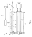
- FIG. 1 is a schematic, lengthwise cross-sectional view of an embodiment of an excimer laser having a feedback system for adjusting the laser based on measurements of light extracted from the output laser beam.
- FIG. 2 is a schematic, lengthwise cross-sectional view of another embodiment of an excimer laser with an alternative feedback arrangement.
- Excimer lasers can emit pulses of ultraviolet radiation and have potentially many practical applications in medicine, industry, and communications.
- Ultraviolet light for example emitted by an excimer laser, may be employed to treat a variety of skin disorders such as, for example, psoriasis and vitiligo.
- exemplary systems and methods for providing such treatment are described in U.S. patent application Ser. No. 10/799,337, filed Feb. 27, 2002, entitled “Treatment of Skin Disorders with UV Light and Cooling,” which is incorporated herein by reference in its entirety.
- Such systems may include an ultraviolet light source, such as a laser (e.g., excimer laser), and a delivery system (e.g., a handpiece).
- the laser energy can be coupled from the laser chamber and delivered to a treatment site (e.g., on a patient) by using a flexible or rigid optical line, such as a fiberoptic cable or liquid light guide.
- the laser energy can also be delivered by using a delivery system including one or more mirrors.
- the light output by the excimer laser may be guided or may propagate in free space such as through the air to a target, e.g., for treatment.
- a target e.g., for treatment.
- an excimer laser is a type of gas laser wherein gases are used to generate ultraviolet light.
- the gas fills an open space between a pair of bulk optic reflectors, e.g., mirrors, arranged to form an optically resonant cavity.
- De-excitation of gaseous molecules provides light that propagates in waves in free space (as opposed to waveguides) between the mirrors. This light reflects back and forth within the gas-filled open space between the mirrors.
- the laser gas introduces gain to the light propagating in the resonator cavity producing lasing. A portion of the laser light passes through one of the mirrors thereby providing a laser beam that can be used for applications such as described above.
- FIG. 1 illustrates a cross-sectional view of an example laser 102 .
- the laser 102 comprises a chamber 12 for containing laser gases. Lasing electrodes 20 , 22 longitudinally extending within the chamber 12 are configured to induce a transverse electrical discharge in laser gases within the chamber 12 . The electrical discharge causes the formation of excited rare gas-halide molecules, whose disassociation results in the emission of ultraviolet photons constituting the laser light.
- the laser further comprises reflective optical elements 14 , 16 (e.g., near totally reflective mirrors, partially reflective mirrors, etc.) that form an optical cavity to establish an optical resonance condition.
- Laser gases within the chamber 12 can be circulated in the space between the lasing electrodes 20 , 22 by a fan 24 .
- the laser gases may be cooled by a heat exchanger, i.e., a structure that removes excess heat, and the like.
- first and second mirrors 14 , 16 are disposed at two opposing internal faces of the chamber 12 .
- these mirrors may comprise bulk mirrors comprising, for example, glass, sapphire, fused silica, or other substrates optically transmissive to the laser light.
- This transmissive substrate has a reflective coating thereon that is reflective to the laser light.
- substrates may transmit UV light while the reflective coatings may reflect UV light.
- Other designs are possible.
- the first mirror 14 is designed to have a nearly 100% reflectance, though in fact there will ineluctably be some modicum of laser energy that is transmitted through the first mirror 14 .
- the mirror may, for example, have a reflectance at the laser wavelength (e.g., 308 nm) of greater than about 99.0% and greater than about 99.9% in some embodiments.
- the second mirror 16 is designed to be partially reflecting.
- the second mirror 16 may, for example, allow about 50% of the laser energy striking it to pass through the mirror, and may reflect about 50% back to the other mirror.
- the second mirror 16 transmits between about 1% and 90% of the laser energy and reflects between about 99% and 10% of the laser energy.
- the first mirror 14 is more reflective and may be substantially more reflective than the second mirror 16 .
- the second mirror 16 is more transmissive and may be substantially more transmissive than the first mirror 14 .
- the energy delivered by the laser 102 may fluctuate.
- a detector 26 e.g., a photodiode
- a partially reflecting surface or mirror 28 e.g., a beam splitter
- the beam splitter 28 may shunt, for example, between about 1% and 5% of the light transmitted through the second mirror 16 into the detector 26 .
- FIG. 2 illustrates another embodiment of a laser 104 including a first mirror 14 and a second mirror 16 .
- An optical detector 26 e.g., a photodiode
- the detector 26 may be placed proximate to the first mirror 14 .
- These collecting optics may comprise bulk optics in the form of a lens or a reflecting surface such as a reflecting mirror.
- collection optics comprising a reflecting surface is an integrating sphere.
- the integrating sphere 30 can capture the leaked optical energy, and then output a portion of the light to the detector 26 .
- the integrating sphere 30 may also homogenize the beam output through the first mirror 14 .
- the term integrating sphere 30 is used to describe the reflective collecting optic used to collect light that passes through the first mirror 14 , even though the reflective optic is more akin to a hemisphere.
- the reflecting optic therefore may be a spherical surface that is more or less than a hemisphere. In other embodiments, the reflective surface need not be spherical in shape. Spheres, facets, or other reflective structures are possible. This reflecting surface may be disposed, e.g., opposite to the first mirror 14 , enclosing or covering a portion of the first mirror 14 , etc., so as to receive light passing through the first mirror 14 . In various embodiments, however, light transmitted through the first mirror 14 reflects from the reflective surface back toward the first mirror 14 .
- This light may be reflected from the first mirror 14 to the detector 26 or may reflect multiple times between the reflective surface and the first mirror 14 until the light is incident on the detector. In this fashion, however, the reflective surface may increase the amount of light transmitted through the first mirror 14 that is received by the detector. Because only a small amount of light may be transmitted by the first mirror 14 , increasing the collection efficiency of the detector 26 is advantageous.
- the detector 26 is linked to, and in communication with, a feedback/control system (“controller”) 32 that is configured to increase or decrease laser energy output, for example depending on whether a fluctuation falls outside a band of acceptable output.
- the detector 26 and the controller 32 may be calibrated, for example by analyzing a relationship between a known quantity of energy and an amount of energy received by the detector 26 . The relationship may then be used to determine how much energy is output from the laser 104 for various amount of energy received by the detector 26 . For example, if the calibration shows that the detector 26 receives about 0.5% of the energy emitted by the laser 104 , and the detector measures 50 milliwatts (mW), then the laser 104 is producing about 1 watt (W) of power.
- mW milliwatts
- the controller 32 is configured to adjust the energy or power output from the laser 104 if the detected energy output differs from a target energy output. For example, if a medical procedure preferably utilizes a power of 1 W, that power would be the target power output for the laser 104 . Over a certain period of time (e.g., the time to complete a treatment procedure), the controller 32 may be programmed to adjust conditions of the laser 104 (e.g., input voltage, gas pressure, temperature) in order to compensate for fluctuations in output power or energy. For example, the controller 32 may be configured to stabilize the output energy to within about 20%, 10%, 5%, or less of a mean power or energy for the duration of a treatment of a patient. Other methods of calibration are also possible.
- conditions of the laser 104 e.g., input voltage, gas pressure, temperature
- the controller 32 may be configured to stabilize the output energy to within about 20%, 10%, 5%, or less of a mean power or energy for the duration of a treatment of a patient. Other methods of calibration are also
- An example benefit of the configuration shown in FIG. 2 is that instead of using, and losing, for example, between about 1% and 5% of the energy from the otherwise useable output from the laser 102 that passes through the second mirror 16 , the otherwise unavoidable and unusable loss from the first mirror 14 is utilized by the laser 104 . Because the portion of the beam used, for example, for a medical procedure, is not passed through a beam splitter 28 such as shown in FIG. 1 , the useable output from the laser, for example, that can be delivered to a patient may be increased. Embodiments such as those depicted in FIG. 2 may suitably be referred to as a “zero loss” laser energy detecting device, as none of the usable laser power/energy is lost due to the detector.
- an additional benefit to disposing the detector 26 so as to receive a portion of the light from the more reflective first mirror 14 , rather than downstream of a reflective surface of a beam splitter 28 is that system cost can be reduced.
- an integrating sphere 30 typically costs less than a beam splitter 28 (e.g., costing about 25% as much).
- the integrating sphere 30 reduces or eliminates measurement errors due to laser beam power density inhomogeneities. Some embodiments may omit the integrating sphere, thereby having a cost similar to a laser without a beam splitter 28 .
Abstract
Description
Claims (16)
Priority Applications (1)
| Application Number | Priority Date | Filing Date | Title |
|---|---|---|---|
| US11/498,382 US7848378B2 (en) | 2005-08-05 | 2006-08-03 | Apparatus and method for monitoring power of a UV laser |
Applications Claiming Priority (2)
| Application Number | Priority Date | Filing Date | Title |
|---|---|---|---|
| US70578905P | 2005-08-05 | 2005-08-05 | |
| US11/498,382 US7848378B2 (en) | 2005-08-05 | 2006-08-03 | Apparatus and method for monitoring power of a UV laser |
Publications (2)
| Publication Number | Publication Date |
|---|---|
| US20070030877A1 US20070030877A1 (en) | 2007-02-08 |
| US7848378B2 true US7848378B2 (en) | 2010-12-07 |
Family
ID=37717569
Family Applications (1)
| Application Number | Title | Priority Date | Filing Date |
|---|---|---|---|
| US11/498,382 Active US7848378B2 (en) | 2005-08-05 | 2006-08-03 | Apparatus and method for monitoring power of a UV laser |
Country Status (1)
| Country | Link |
|---|---|
| US (1) | US7848378B2 (en) |
Cited By (3)
| Publication number | Priority date | Publication date | Assignee | Title |
|---|---|---|---|---|
| US20100232469A1 (en) * | 2007-03-27 | 2010-09-16 | Photomedex | Method and apparatus for efficiently operating a gas discharge excimer laser |
| US20110004280A1 (en) * | 2000-10-20 | 2011-01-06 | Photomedex | Treatment of skin disorders with uv light |
| US20110196457A1 (en) * | 2001-10-18 | 2011-08-11 | Photomedex | Device for uv photo-therapy |
Families Citing this family (2)
| Publication number | Priority date | Publication date | Assignee | Title |
|---|---|---|---|---|
| US20070032844A1 (en) * | 2005-08-05 | 2007-02-08 | Levatter Jeffrey I | Targeted UV phototherapy light block |
| US20070030876A1 (en) * | 2005-08-05 | 2007-02-08 | Levatter Jeffrey I | Apparatus and method for purging and recharging excimer laser gases |
Citations (21)
| Publication number | Priority date | Publication date | Assignee | Title |
|---|---|---|---|---|
| US3404349A (en) | 1964-04-28 | 1968-10-01 | Bell Telephone Labor Inc | Optical maser for higher order modes |
| US3437955A (en) | 1964-12-29 | 1969-04-08 | Bell Telephone Labor Inc | Phase locked laser oscillator |
| US3471803A (en) | 1967-04-28 | 1969-10-07 | Hughes Aircraft Co | Laser having a stabilized output spectrum |
| US3572948A (en) | 1967-10-31 | 1971-03-30 | Comp Generale Electricite | Apparatus for measuring the electron density of a plasma |
| US3596201A (en) | 1970-06-08 | 1971-07-27 | Hughes Aircraft Co | Frequency stabilized laser |
| US3831108A (en) | 1972-04-21 | 1974-08-20 | Anvar | Method of frequency and intensity stabilization of the radiation emitted by a high-power gas laser and a gas laser for the application of said method |
| US4891818A (en) * | 1987-08-31 | 1990-01-02 | Acculase, Inc. | Rare gas-halogen excimer laser |
| US5463650A (en) * | 1992-07-17 | 1995-10-31 | Kabushiki Kaisha Komatsu Seisakusho | Apparatus for controlling output of an excimer laser device |
| US5642374A (en) * | 1994-04-12 | 1997-06-24 | Kabushiki Kaisha Komatsu Seisakusho | Excimer laser device |
| US5657334A (en) * | 1996-02-15 | 1997-08-12 | Cymer, Inc. | External high voltage control for a laser system |
| US6018535A (en) * | 1998-04-23 | 2000-01-25 | Ando Electric Co., Ltd. | External cavity type wavelength-tunable light source |
| US6272158B1 (en) * | 1998-06-01 | 2001-08-07 | Lambda Physik Ag | Method and apparatus for wavelength calibration |
| US20020126717A1 (en) * | 2001-03-09 | 2002-09-12 | The Furukawa Electric Co., Ltd. | Optical module and method of making the same |
| US6526071B1 (en) * | 1998-10-16 | 2003-02-25 | New Focus, Inc. | Tunable laser transmitter with internal wavelength grid generators |
| US20030161374A1 (en) * | 2001-11-21 | 2003-08-28 | Lambda Physik Ag | High-resolution confocal Fabry-Perot interferometer for absolute spectral parameter detection of excimer laser used in lithography applications |
| US6661815B1 (en) * | 2002-12-31 | 2003-12-09 | Intel Corporation | Servo technique for concurrent wavelength locking and stimulated brillouin scattering suppression |
| US6721344B2 (en) * | 2001-06-26 | 2004-04-13 | Komatsu Ltd. | Injection locking type or MOPA type of laser device |
| US6724797B2 (en) * | 2001-07-06 | 2004-04-20 | Intel Corporation | External cavity laser with selective thermal control |
| US6741627B2 (en) * | 2001-12-28 | 2004-05-25 | Ushio Denki Kabushiki Kaisya | Photolithographic molecular fluorine laser system |
| US20050015124A1 (en) | 2000-10-20 | 2005-01-20 | Irwin Dean S. | Treatment of skin disorders with UV light and cooling |
| US20050175055A1 (en) * | 2004-02-11 | 2005-08-11 | Levatter Jeffrey I. | Rare gas-halogen excimer lasers with baffles |
-
2006
- 2006-08-03 US US11/498,382 patent/US7848378B2/en active Active
Patent Citations (22)
| Publication number | Priority date | Publication date | Assignee | Title |
|---|---|---|---|---|
| US3404349A (en) | 1964-04-28 | 1968-10-01 | Bell Telephone Labor Inc | Optical maser for higher order modes |
| US3437955A (en) | 1964-12-29 | 1969-04-08 | Bell Telephone Labor Inc | Phase locked laser oscillator |
| US3471803A (en) | 1967-04-28 | 1969-10-07 | Hughes Aircraft Co | Laser having a stabilized output spectrum |
| US3572948A (en) | 1967-10-31 | 1971-03-30 | Comp Generale Electricite | Apparatus for measuring the electron density of a plasma |
| US3596201A (en) | 1970-06-08 | 1971-07-27 | Hughes Aircraft Co | Frequency stabilized laser |
| US3831108A (en) | 1972-04-21 | 1974-08-20 | Anvar | Method of frequency and intensity stabilization of the radiation emitted by a high-power gas laser and a gas laser for the application of said method |
| US4891818A (en) * | 1987-08-31 | 1990-01-02 | Acculase, Inc. | Rare gas-halogen excimer laser |
| US5463650A (en) * | 1992-07-17 | 1995-10-31 | Kabushiki Kaisha Komatsu Seisakusho | Apparatus for controlling output of an excimer laser device |
| US5642374A (en) * | 1994-04-12 | 1997-06-24 | Kabushiki Kaisha Komatsu Seisakusho | Excimer laser device |
| US5657334A (en) * | 1996-02-15 | 1997-08-12 | Cymer, Inc. | External high voltage control for a laser system |
| US6018535A (en) * | 1998-04-23 | 2000-01-25 | Ando Electric Co., Ltd. | External cavity type wavelength-tunable light source |
| US6272158B1 (en) * | 1998-06-01 | 2001-08-07 | Lambda Physik Ag | Method and apparatus for wavelength calibration |
| US6608848B2 (en) * | 1998-06-01 | 2003-08-19 | Lambda Physik Ag | Method and apparatus for wavelength calibration |
| US6526071B1 (en) * | 1998-10-16 | 2003-02-25 | New Focus, Inc. | Tunable laser transmitter with internal wavelength grid generators |
| US20050015124A1 (en) | 2000-10-20 | 2005-01-20 | Irwin Dean S. | Treatment of skin disorders with UV light and cooling |
| US20020126717A1 (en) * | 2001-03-09 | 2002-09-12 | The Furukawa Electric Co., Ltd. | Optical module and method of making the same |
| US6721344B2 (en) * | 2001-06-26 | 2004-04-13 | Komatsu Ltd. | Injection locking type or MOPA type of laser device |
| US6724797B2 (en) * | 2001-07-06 | 2004-04-20 | Intel Corporation | External cavity laser with selective thermal control |
| US20030161374A1 (en) * | 2001-11-21 | 2003-08-28 | Lambda Physik Ag | High-resolution confocal Fabry-Perot interferometer for absolute spectral parameter detection of excimer laser used in lithography applications |
| US6741627B2 (en) * | 2001-12-28 | 2004-05-25 | Ushio Denki Kabushiki Kaisya | Photolithographic molecular fluorine laser system |
| US6661815B1 (en) * | 2002-12-31 | 2003-12-09 | Intel Corporation | Servo technique for concurrent wavelength locking and stimulated brillouin scattering suppression |
| US20050175055A1 (en) * | 2004-02-11 | 2005-08-11 | Levatter Jeffrey I. | Rare gas-halogen excimer lasers with baffles |
Cited By (6)
| Publication number | Priority date | Publication date | Assignee | Title |
|---|---|---|---|---|
| US20110004280A1 (en) * | 2000-10-20 | 2011-01-06 | Photomedex | Treatment of skin disorders with uv light |
| US8486056B2 (en) | 2000-10-20 | 2013-07-16 | Photomedex | Treatment of skin disorders with UV light |
| US9162078B2 (en) | 2000-10-20 | 2015-10-20 | Mela Sciences, Inc. | Treatment of skin disorders with UV light |
| US20110196457A1 (en) * | 2001-10-18 | 2011-08-11 | Photomedex | Device for uv photo-therapy |
| US8454669B2 (en) | 2001-10-18 | 2013-06-04 | Photomedex | Device for UV photo-therapy |
| US20100232469A1 (en) * | 2007-03-27 | 2010-09-16 | Photomedex | Method and apparatus for efficiently operating a gas discharge excimer laser |
Also Published As
| Publication number | Publication date |
|---|---|
| US20070030877A1 (en) | 2007-02-08 |
Similar Documents
| Publication | Publication Date | Title |
|---|---|---|
| US20220045470A1 (en) | Broadband Light Source Device and Method of Creating Broadband Light Pulses | |
| Bowman et al. | Minimizing heat generation in solid-state lasers | |
| JP3228423B2 (en) | Gas detection system and gas detection method | |
| US5412681A (en) | Slab-waveguide CO2 laser | |
| JP2000236130A (en) | Molecular fluorine (f2) laser and method of generating and outputting f2 laser beam | |
| US7848378B2 (en) | Apparatus and method for monitoring power of a UV laser | |
| US8942265B2 (en) | Raman converting laser systems | |
| US5946093A (en) | Particle detection system and method employing an upconversion laser | |
| JP2003513437A (en) | Line narrowing module for high power laser | |
| US7777886B2 (en) | Optical system including a weak lens and a beam translation plate for selectively coupling to the lowest order mode of an optical resonator | |
| EP1521942A2 (en) | Gas discharge ultraviolet wavemeter with enhanced illumination | |
| US10151640B2 (en) | Light beam measurement device, laser apparatus, and light beam separator | |
| WO2016143071A1 (en) | Solid-state laser device, fiber amplifier system, and solid-state laser system | |
| US6516013B1 (en) | Laser beam monitoring apparatus and method | |
| JP5657139B2 (en) | CO2 laser device and CO2 laser processing device | |
| US20020101900A1 (en) | Molecular fluorine laser with single spectral line and polarized output | |
| US6735232B2 (en) | Laser with versatile output energy | |
| US6717973B2 (en) | Wavelength and bandwidth monitor for excimer or molecular fluorine laser | |
| JP2001203416A (en) | Laser system | |
| TW201301693A (en) | Gas laser amplifying device | |
| JP2002084026A (en) | F2 laser | |
| KR20210113306A (en) | Resonant optical cavity system with optical feedback suitable for trace gas detection by Raman spectroscopy | |
| US6839375B1 (en) | On-line quality control of the key optical components in lithography lasers using laser induced fluorescence | |
| JP2009260358A (en) | Apparatus for side-surface light emission fiber laser | |
| US6570901B2 (en) | Excimer or molecular fluorine laser having lengthened electrodes |
Legal Events
| Date | Code | Title | Description |
|---|---|---|---|
| AS | Assignment |
Owner name: PHOTOMEDEX, INC., PENNSYLVANIA Free format text: ASSIGNMENT OF ASSIGNORS INTEREST;ASSIGNOR:LEVATTER, JEFFREY I.;REEL/FRAME:018155/0806 Effective date: 20060802 |
|
| AS | Assignment |
Owner name: PERSEUS PARTNERS VII, L.P.,DISTRICT OF COLUMBIA Free format text: SECURITY AGREEMENT;ASSIGNORS:PHOTOMEDEX, INC.;PROCYTE CORPORATION;PHOTO THERAPEUTICS, INC.;AND OTHERS;REEL/FRAME:024244/0480 Effective date: 20100319 Owner name: PERSEUS PARTNERS VII, L.P., DISTRICT OF COLUMBIA Free format text: SECURITY AGREEMENT;ASSIGNORS:PHOTOMEDEX, INC.;PROCYTE CORPORATION;PHOTO THERAPEUTICS, INC.;AND OTHERS;REEL/FRAME:024244/0480 Effective date: 20100319 |
|
| STCF | Information on status: patent grant |
Free format text: PATENTED CASE |
|
| AS | Assignment |
Owner name: SLT TECHNOLOGIES, INC., PENNSYLVANIA Free format text: RELEASE OF SECURITY INTEREST IN PATENTS;ASSIGNOR:PERSEUS PARTNERS VII, L.P.;REEL/FRAME:027374/0134 Effective date: 20111213 Owner name: PROCYTE CORPORATION, PENNSYLVANIA Free format text: RELEASE OF SECURITY INTEREST IN PATENTS;ASSIGNOR:PERSEUS PARTNERS VII, L.P.;REEL/FRAME:027374/0134 Effective date: 20111213 Owner name: PHOTOMEDEX, INC., PENNSYLVANIA Free format text: RELEASE OF SECURITY INTEREST IN PATENTS;ASSIGNOR:PERSEUS PARTNERS VII, L.P.;REEL/FRAME:027374/0134 Effective date: 20111213 Owner name: PHOTO THERAPEUTICS, INC., PENNSYLVANIA Free format text: RELEASE OF SECURITY INTEREST IN PATENTS;ASSIGNOR:PERSEUS PARTNERS VII, L.P.;REEL/FRAME:027374/0134 Effective date: 20111213 |
|
| FPAY | Fee payment |
Year of fee payment: 4 |
|
| AS | Assignment |
Owner name: JPMORGAN CHASE BANK, N.A., AS ADMINISTRATIVE AGENT Free format text: SECURITY INTEREST;ASSIGNORS:PHOTOMEDEX, INC.;GATORADE ACQUISITION CORP.;RADIANCY, INC.;AND OTHERS;REEL/FRAME:032892/0586 Effective date: 20140512 |
|
| AS | Assignment |
Owner name: RADIANCY, INC., NEW YORK Free format text: RELEASE BY SECURED PARTY;ASSIGNOR:JPMORGAN CHASE BANK, N.A.;REEL/FRAME:036007/0222 Effective date: 20150619 Owner name: GATORADE ACQUISITION CORP., PENNSYLVANIA Free format text: RELEASE BY SECURED PARTY;ASSIGNOR:JPMORGAN CHASE BANK, N.A.;REEL/FRAME:036007/0222 Effective date: 20150619 Owner name: LUMIERE, INC., PENNSYLVANIA Free format text: RELEASE BY SECURED PARTY;ASSIGNOR:JPMORGAN CHASE BANK, N.A.;REEL/FRAME:036007/0222 Effective date: 20150619 Owner name: PHOTOMEDEX TECHNOLOGY, INC., PENNSYLVANIA Free format text: RELEASE BY SECURED PARTY;ASSIGNOR:JPMORGAN CHASE BANK, N.A.;REEL/FRAME:036007/0222 Effective date: 20150619 Owner name: PHOTOMEDEX, INC., PENNSYLVANIA Free format text: RELEASE BY SECURED PARTY;ASSIGNOR:JPMORGAN CHASE BANK, N.A.;REEL/FRAME:036007/0222 Effective date: 20150619 |
|
| AS | Assignment |
Owner name: PHOTOMEDEX TECHNOLOGY, INC., PENNSYLVANIA Free format text: NUNC PRO TUNC ASSIGNMENT;ASSIGNOR:PHOTOMEDEX, INC.;REEL/FRAME:036236/0201 Effective date: 20121227 Owner name: MELA SCIENCES, INC., PENNSYLVANIA Free format text: ASSIGNMENT OF ASSIGNORS INTEREST;ASSIGNOR:PHOTOMEDEX TECHNOLOGY, INC.;REEL/FRAME:036236/0243 Effective date: 20150622 |
|
| AS | Assignment |
Owner name: MIDCAP FINANCIAL TRUST, AS AGENT, MARYLAND Free format text: SECURITY INTEREST;ASSIGNOR:MELA SCIENCES, INC.;REEL/FRAME:037391/0451 Effective date: 20151230 |
|
| AS | Assignment |
Owner name: STRATA SKIN SCIENCES, INC., PENNSYLVANIA Free format text: CHANGE OF NAME;ASSIGNOR:MELA SCIENCES, INC.;REEL/FRAME:044255/0358 Effective date: 20151231 |
|
| MAFP | Maintenance fee payment |
Free format text: PAYMENT OF MAINTENANCE FEE, 8TH YR, SMALL ENTITY (ORIGINAL EVENT CODE: M2552) Year of fee payment: 8 |
|
| AS | Assignment |
Owner name: STRATA SKIN SCIENCES, INC., PENNSYLVANIA Free format text: RELEASE BY SECURED PARTY;ASSIGNOR:MIDCAP FINANCIAL TRUST;REEL/FRAME:051558/0510 Effective date: 20200116 |
|
| AS | Assignment |
Owner name: MIDCAP FINANCIAL TRUST, MARYLAND Free format text: SECURITY INTEREST;ASSIGNOR:STRATA SKIN SCIENCES, INC.;REEL/FRAME:057717/0796 Effective date: 20210930 |
|
| MAFP | Maintenance fee payment |
Free format text: PAYMENT OF MAINTENANCE FEE, 12TH YR, SMALL ENTITY (ORIGINAL EVENT CODE: M2553); ENTITY STATUS OF PATENT OWNER: SMALL ENTITY Year of fee payment: 12 |