US7856830B2 - Noise reducing combustor - Google Patents

Noise reducing combustor Download PDF

Info

Publication number
US7856830B2
US7856830B2 US11/441,225 US44122506A US7856830B2 US 7856830 B2 US7856830 B2 US 7856830B2 US 44122506 A US44122506 A US 44122506A US 7856830 B2 US7856830 B2 US 7856830B2
Authority
US
United States
Prior art keywords
combustor
effusion holes
effusion
section
primary section
Prior art date
Legal status (The legal status is an assumption and is not a legal conclusion. Google has not performed a legal analysis and makes no representation as to the accuracy of the status listed.)
Active, expires
Application number
US11/441,225
Other versions
US20070271926A1 (en
Inventor
Hisham Alkabie
Current Assignee (The listed assignees may be inaccurate. Google has not performed a legal analysis and makes no representation or warranty as to the accuracy of the list.)
Pratt and Whitney Canada Corp
Original Assignee
Pratt and Whitney Canada Corp
Priority date (The priority date is an assumption and is not a legal conclusion. Google has not performed a legal analysis and makes no representation as to the accuracy of the date listed.)
Filing date
Publication date
Assigned to PRATT & WHITNEY CANADA CORP. reassignment PRATT & WHITNEY CANADA CORP. ASSIGNMENT OF ASSIGNORS INTEREST (SEE DOCUMENT FOR DETAILS). Assignors: ALKABIE, HISHAM
Application filed by Pratt and Whitney Canada Corp filed Critical Pratt and Whitney Canada Corp
Priority to US11/441,225 priority Critical patent/US7856830B2/en
Priority to CA2587058A priority patent/CA2587058C/en
Publication of US20070271926A1 publication Critical patent/US20070271926A1/en
Application granted granted Critical
Publication of US7856830B2 publication Critical patent/US7856830B2/en
Active legal-status Critical Current
Adjusted expiration legal-status Critical

Links

Images

Classifications

    • FMECHANICAL ENGINEERING; LIGHTING; HEATING; WEAPONS; BLASTING
    • F23COMBUSTION APPARATUS; COMBUSTION PROCESSES
    • F23RGENERATING COMBUSTION PRODUCTS OF HIGH PRESSURE OR HIGH VELOCITY, e.g. GAS-TURBINE COMBUSTION CHAMBERS
    • F23R3/00Continuous combustion chambers using liquid or gaseous fuel
    • F23R3/02Continuous combustion chambers using liquid or gaseous fuel characterised by the air-flow or gas-flow configuration
    • F23R3/04Air inlet arrangements
    • F23R3/06Arrangement of apertures along the flame tube
    • FMECHANICAL ENGINEERING; LIGHTING; HEATING; WEAPONS; BLASTING
    • F23COMBUSTION APPARATUS; COMBUSTION PROCESSES
    • F23RGENERATING COMBUSTION PRODUCTS OF HIGH PRESSURE OR HIGH VELOCITY, e.g. GAS-TURBINE COMBUSTION CHAMBERS
    • F23R3/00Continuous combustion chambers using liquid or gaseous fuel
    • F23R3/42Continuous combustion chambers using liquid or gaseous fuel characterised by the arrangement or form of the flame tubes or combustion chambers
    • F23R3/50Combustion chambers comprising an annular flame tube within an annular casing
    • FMECHANICAL ENGINEERING; LIGHTING; HEATING; WEAPONS; BLASTING
    • F23COMBUSTION APPARATUS; COMBUSTION PROCESSES
    • F23RGENERATING COMBUSTION PRODUCTS OF HIGH PRESSURE OR HIGH VELOCITY, e.g. GAS-TURBINE COMBUSTION CHAMBERS
    • F23R3/00Continuous combustion chambers using liquid or gaseous fuel
    • F23R3/42Continuous combustion chambers using liquid or gaseous fuel characterised by the arrangement or form of the flame tubes or combustion chambers
    • F23R3/54Reverse-flow combustion chambers
    • FMECHANICAL ENGINEERING; LIGHTING; HEATING; WEAPONS; BLASTING
    • F23COMBUSTION APPARATUS; COMBUSTION PROCESSES
    • F23RGENERATING COMBUSTION PRODUCTS OF HIGH PRESSURE OR HIGH VELOCITY, e.g. GAS-TURBINE COMBUSTION CHAMBERS
    • F23R2900/00Special features of, or arrangements for continuous combustion chambers; Combustion processes therefor
    • F23R2900/03041Effusion cooled combustion chamber walls or domes

Definitions

  • the invention relates generally to gas turbine engines and, more particularly, to an improved combustor for such engines providing low noise levels.
  • Noise produced by gas turbine engines is largely caused by pressure and acoustic vibrations which can occur in and around the combustion chamber under certain conditions. Many advancements have been made to reduce the overall noise levels generated by gas turbine engines. However, few have enabled the reduction of noise generated by the combustion chamber of such a gas turbine engine.
  • the noise of the combustion chamber is damped by providing Helmholtz resonators as damping elements to eliminate undesirable vibrations, which contribute to noise levels.
  • combustors incorporating Helmholtz resonators are generally complex to manufacture.
  • the combustors have a double wall construction, i.e. interconnected inner walls defining the combustion chamber surrounded by interconnected outer walls to define an annular free space therebetween.
  • the outer walls have impingement holes defined therein which permit compressed air from around the combustion chamber to pass through to impinge on the inner walls.
  • the inner walls have effusion holes defined therein to permit the air to effuse into the combustion chamber.
  • the double wall construction generally renders the combustor more complex and costly to manufacture.
  • the present invention provides a combustor for a gas turbine engine, the combustor comprising inner and outer liners defining an annular combustion chamber therebetween, the combustion chamber having a primary section adapted to receive a plurality of fuel nozzles and a secondary section defined downstream of the primary section, the liners having a plurality of angled effusion holes defined therethrough in the primary and secondary sections, each of the effusion holes being defined through a corresponding one of the liners at a first angle with respect to a surface of the corresponding one of the liners and at a second angle with respect to a corresponding radial plane extending radially from a central axis of the combustor, a density of the effusion holes defined in the primary section being at least equal to a density of the effusion-holes defined in the secondary section.
  • the present invention provides a method of reducing noise emissions of a gas turbine engine, the method comprising introducing an effusion airflow from a compressor section of the engine through a wall of a combustor of the engine, and directing the effusion airflow along a direction extending at a first angle with respect to a surface of the wall and at a second angle with respect to a radial plane extending radially from a central axis of the combustor to produce a time delay between a noise generated in the compressor section and at least one of a noise generated in the combustor and a noise amplified in the combustor.
  • the present invention provides a method of manufacturing a combustor for reducing noise emissions in a gas turbine engine, the method comprising selecting a first effusion hole density for a primary combustion section of the combustor according to a desired frequency range of the noise emissions to be attenuated, selecting a second effusion hole density for a remaining section of the combustor, the second density being smaller than the first density, and defining effusion holes through walls of the combustor following hole directions angled with respect to a corresponding one of the walls and to a respective radial plane extending radially from a central axis of the combustor, the effusion holes being defined in the primary section according to the first density and in the remaining section according to the second density.
  • FIG. 1 is a schematic, cross-sectional view of a gas turbine engine
  • FIG. 2 is a cross-sectional view of part of the gas turbine engine of FIG. 1 , including a combustor according to a particular embodiment of the present invention
  • FIG. 3A is a top view of a portion of an outer liner of the combustor of FIG. 2 ;
  • FIG. 3B is bottom view of a portion of an inner liner of the combustor of FIG. 2 ;
  • FIG. 4 is a cross-sectional view of the combustor of FIG. 2 , identifying different regions and sections thereof.
  • FIG. 1 illustrates a gas turbine engine 10 of a type preferably provided for use in subsonic flight, generally comprising in serial flow communication a fan 12 through which ambient air is propelled, a multistage compressor 14 for pressurizing the air, a combustor 16 in which the compressed air is mixed with fuel and ignited for generating an annular stream of hot combustion gases, and a turbine section 18 for extracting energy from the combustion gases.
  • a gas turbine engine 10 of a type preferably provided for use in subsonic flight, generally comprising in serial flow communication a fan 12 through which ambient air is propelled, a multistage compressor 14 for pressurizing the air, a combustor 16 in which the compressed air is mixed with fuel and ignited for generating an annular stream of hot combustion gases, and a turbine section 18 for extracting energy from the combustion gases.
  • the air exiting the compressor 14 passes through a diffuser 20 and enters a gas generator case 22 which surrounds the combustor 16 .
  • the combustor 16 includes interconnected inner and outer annular walls or liners 24 , 26 connected by a combustor dome which receive the airflow circulating in the gas generator case on outer surfaces 28 , 30 thereof, and which define an annular enclosure or combustion chamber 36 between inner surfaces 32 , 34 thereof.
  • the annular stream of hot combustion gases travels through the combustion chamber 36 and passes through an array of compressor turbine (CT) vanes 38 upon entering the turbine section 18 .
  • CT compressor turbine
  • the combustor 16 includes a primary or combustion section 40 , where the fuel nozzles (not shown) are received, and an intermediate and dilution section 42 , which is defined downstream of the primary section 40 .
  • the outer liner 26 has a series of fuel nozzle holes 44 (also shown in FIG. 3A ) defined therein in the primary section 4 G, each hole 44 being adapted to receive a fuel nozzle (not shown).
  • the primary section 40 is the region in which the chemical reaction of combustion is completed, and has the highest flame temperature within the combustor.
  • the downstream section 42 has a secondary zone characterized by first additional air jets to quench the hot product generated by the primary section; and a dilution zone where second additional jets quench the hot product and profile the hot product prior to discharge to turbine section.
  • the inner and outer liners 24 , 26 have a plurality of effusion holes 46 a,b,c,d defined therethrough, through which the airflow within the gas generator case 22 enters the annular enclosure 36 .
  • Each effusion hole 46 a,b,c,d defines a hole direction 48 a,b,c,d , extending along a central axis of the hole and directed toward the enclosure 36 .
  • the hole direction 48 a,b,c,d of each effusion hole 46 a,b,c,d thus also corresponds to the general direction of the velocity of the airflow flowing through that hole 46 a,b,c,d .
  • an imaginary radial plane 50 is defined for each effusion hole 46 a,b,c,d , extending radially from the central axis 52 (see FIG. 2 ) of the combustor 16 and intersecting the corresponding effusion hole 46 a,b,c,d , this radial plane 50 being shown for some of the effusion holes 46 a,b,c,d in FIGS. 3A-3B and corresponding to the plane of the Figure for the effusion holes 46 a,b,c,d depicted in FIG. 2 .
  • each effusion hole 46 a,b,c,d extends at an acute angle with respect to the corresponding liner 24 , 26 , the projection ⁇ of that angle on the corresponding radial plane 50 being shown in FIG. 2 .
  • the projected angle ⁇ of each angled effusion hole 46 a,b,c,d is thus defined as the angle measured from the corresponding liner 24 , 26 , for example the outer surface 28 , 30 thereof, to the projection of the hole direction 48 a,b,c,d on the corresponding radial plane 50 .
  • each effusion hole 46 a,b,c,d also extends at an acute angle with respect to the corresponding radial plane 50 , the projection 0 of that angle on the outer surface 28 , 30 of the corresponding liner 24 , 26 being shown in FIGS. 3A-3B .
  • the projected angle ⁇ of each angled effusion hole 46 a,b,c,d is thus defined as the angle measured from the corresponding radial plane 50 to the projection of the hole direction 48 a,b,c,d on the outer surface 28 , 30 of the corresponding liner 24 , 26 .
  • Preferred values for the projected angles ⁇ define angles between the hole directions 48 a,b,c,d and the corresponding outer surface 28 , 30 of between 20° and 30°, and the projected angles ⁇ are preferably defined between 30° and 90° and most preferably approximately 45°.
  • Streamwise and spanwise distances between adjacent effusion holes 46 a,b,c,d (shown respectively at x and y in FIGS. 3A-3B ) is preferably between 2 to 5 times the effusion hole diameter.
  • the diameter of the effusion holes 46 a,b,c,d is preferably between 0.018 and 0.035 inches depending on the engine application, size of the combustor 16 and thickness of the liners 24 , 26 , with preferred values of approximately 0.020 inches for the effusion holes 46 a,c defined in the primary section 40 and approximately 0.030 inches for the remaining effusion holes 46 b,d in order to reduce manufacturing time and cost.
  • a longitudinal component 54 a,b,c,d is defined for each angled hole direction 48 a,b,c,d , extending tangentially to the corresponding liner inner surface 32 , 34 and in the radial plane of the hole.
  • the longitudinal component 54 a,b,c,d of each angled hole direction 48 a,b,c,d generally corresponds to a longitudinal component of the direction of the velocity of the airflow coming through the corresponding effusion hole 46 a,b,c,d.
  • the longitudinal component 54 a of each effusion hole 46 a defined in the outer liner 26 in the primary section 40 is directed away from the downstream section 42
  • the longitudinal component 54 c of each effusion hole 46 c defined in the inner liner 24 in the primary section 40 is directed toward the downstream section 42
  • the longitudinal component 54 b,d of each effusion hole 46 b,d defined in the downstream section 42 is directed away from the primary section 40 .
  • the effusion holes 46 a,b,c,d are angled following the direction of the airflow coming out of the diffuser 20 , which is illustrated by arrows 58 , 60 in FIG. 2 .
  • a tangential component 56 a,b,c,d is also defined for each angled hole direction 48 a,b,c,d , extending tangentially to the corresponding liner inner surface 32 , 34 and perpendicularly to the central axis 52 of the combustor 16 .
  • the tangential component 56 a,b,c,d , of each angled hole direction 48 a,b,c,d generally corresponds to a tangential component of the direction of the velocity of the airflow coming through the corresponding effusion hole 46 a,b,c,d.
  • Effusion holes 46 a,b,c,d having a longitudinal component 54 a,b,c,d and/or a tangential component 56 a,b,c,d with a different orientation than those described above are also considered, depending on the characteristics of the flow within the combustor 16 .
  • a first series of effusion holes oriented to complement the flow within the combustor 16 as described above can be used in combination with a second series of effusion holes oriented partially or totally against the flow within the combustor while reducing the noise emissions thereof as will be further detailed below.
  • the effusion holes 46 a,b,c,d attenuate the broadband low frequency range of noise generated by the compressed air delivered to the combustor 16 from the compressor 14 and/or the noise generated or amplified by the combustor 16 which propagates to other parts of the engine 10 .
  • This noise attenuation effect is obtained through a shift of phase between the noise from the compressor 14 and the noise from the combustor 16 as well as through a reduction in the amplitude of the combustor noise emissions.
  • the number and size of the effusion holes 46 a,b,c,d define a relative effusion open area Ac for each portion of the combustor 16 being considered (e.g. the entire combustor 16 or part or all of one or both of the sections 40 , 42 ).
  • This relative open area Ac is simply defined by the ratio of the total area of the effusion holes 46 a,b,c,d defined in the portion of the combustor 16 being considered, AhO,S, over the area of the combustor 16 in that portion (i.e. the corresponding part of the liner outer surface(s) 28 , 30 ),
  • a combustor is simply defined by the ratio of the total area of the effusion holes 46 a,b,c,d defined in the portion of the combustor 16 being considered, AhO,S, over the area of the combustor 16 in that portion (i.e. the corresponding part of the liner outer surface(s) 28 , 30 ),
  • a combustor
  • each combustor portion considered defined by the corresponding effusion holes 46 a,b,c,d is used to define a geometrical parameter, the transparency coefficient ⁇ c , which is defined for each portion as follows:
  • t is the thickness of the corresponding liner(s) 24 , 26
  • a is the shortest distance between adjacent effusion holes 46 a,b,c,d
  • b is the distance between adjacent effusion holes 46 a,b,c,d measured from center to center
  • d is the diameter of the effusion holes 46 a,b,c,d , with t, a, b and d being defined in inches.
  • C 1 , C 2 and C 3 are constants for each range of attenuated frequencies f a .
  • the constants C 1 , C 2 and C 3 can be experimentally evaluated, for example by measuring the frequency ranges imposed on an engine core (e.g. using microphones and/or pressure transducers) of an engine simultaneously fitted with various combustors, each combustor having effusion holes defined therein which correspond to a specific and different transparency index ⁇ c . From the results, the constant C 1 , C 2 and C 3 can be extrapolated.
  • a specific range of frequencies f a to be attenuated can be targeted, for example a range of 0-20 kHz.
  • the primary section 40 is most susceptible to generate any frequencies f a to be attenuated, for example through the compressor flow, the fuel nozzle feed pressure for both air and fuel and/or the heat release of the combustion process. Any perturbation can also bring the structure of the combustor 16 into a similar mode as the frequencies generated by other parts of the engine 10 , thus amplifying these frequencies f a to be attenuated, starting immediately at the primary section 40 where the combustion takes place.
  • An increased density of effusion holes 46 a,b defined in the primary section 40 helps in absorbing some of the energy generated by the frequencies f a to be attenuated.
  • the density of the effusion holes 46 a,b,c,d determines the static and dynamic pressures redistributions that act as energy dissipaters to reduce the sound power level (amplitude).
  • a ratio between the hole density in the primary section 40 and in the downstream section 42 equal to or greater than 1.
  • the density of the effusion holes 46 a,c defined in the primary section 40 is at least equal, and preferably greater, than the density of the effusion holes 46 b,d defined in the downstream section 42 .
  • the outer liner 26 is shown as being divided in three regions, namely region A located in primary section 40 and regions B and B′ located in downstream section 42
  • the inner liner 24 is shown as being divided in two regions, namely region C located in the primary section 40 and region D located in the downstream section 42 .
  • the preferred relationship between the hole densities in these different regions is thus defined as:
  • n A+C is the mean hole density over regions A and C (i.e. the primary section 40 ) and n B+B′+D is the mean hole density over regions B, B′ and D (i.e. the downstream section 42 ).
  • the maximum value for the density of the effusion holes 46 a,c defined in the primary section 40 i.e. n A+C ) is determined based on conditions producing a quenching of the combustion products near the combustor inner surfaces 32 , 34 which would produce engine starting problems.
  • each discharge coefficient Cd has a value between 0 (total blockage) and 1 (fully open).
  • Each discharge coefficient Cd depends on the approach velocity of the airflow but also on flow blockage and restriction, i.e. the number, size and shape of the corresponding effusion holes 46 a,b,c,d (e.g. l/d where l is the length of the hole and d is the mean diameter, the length l being influenced by the projected angles ⁇ , ⁇ ).
  • the effective open area ACd is thus related to the dynamic flow of the air through the effusion holes 46 a,b,c,d , and is used to calculate the combustor pressure drop AP across the combustor wall 24 , 26 according to the following:
  • the shift of phase between noise from the compressor 14 and noise from the combustor 16 mentioned above is illustrated by a time delay T delay imposed on the low frequency vibrations generated by the compressor 14 with respect to the noise generated by the combustion process in the combustor 16 .
  • This time delay T delay is imposed by the deflection of the air entering the angled effusion holes 46 a,b,c,d , along two directions (projected angles ⁇ , ⁇ ).
  • the double angle ( ⁇ , ⁇ ) of the effusion holes 46 a,b,c,d shifts the noise from the compressor 14 along two directions which reduces the likelihood that it will be coupled with the noise from the combustor 16 .
  • the time delay T delay produces a decoupling effect on the noise from the compressor 14 and the combustor 16 , thus further reducing the noise emissions of the engine 10 .
  • T delay f [( x/d ),( y/d ), ⁇ P local , ( ⁇ / ⁇ )]
  • x is the streamwise distance between adjacent effusion holes 46 a,b,c,d (shown in FIGS. 3A-3B )
  • y is the spanwise distance between adjacent effusion holes 46 a,b,c,d (shown in FIGS. 3A-3B )
  • d is the diameter of the effusion holes 46 a,b,c,d
  • ⁇ P local is the pressure differential across the combustor liner 24 , 26 for the combustor portion considered (which is a function of ACd as described above)
  • is the projected angle of the hole direction 48 a,b,c,d to the corresponding outer surface 28 , 30
  • is the projected angle of the hole direction 48 a,b,c,d to the respective radial plane 50 .
  • the decoupling time delay T delay is specific for each section 40 , 42 of the combustor 16 . However, as explained above, as most of the reaction between fuel/air happens in the primary section 40 where the majority of the heat is released, the decoupling time delay T delay corresponding to primary section 40 , where the combustion process is initiated and the flame front stabilises, is the one that is preferably controlled.
  • the angle ratio ⁇ / ⁇ is mainly responsible for creating the time delay T delay , which produces the frequency phase shift causing the decoupling action between the noise of the compressor 14 and of the combustor 16 .
  • the decoupling time delay T delay is also a function of the geometrical arrangement of the combustor holes (x,y,d), and of the pressure drop ( ⁇ P local ) across the combustor liners 24 , 26 which is a measure of the intensity of the turbulence of the airflow and which is related to the geometry of the effusion holes through its relation to the effective open area ACd, as described above.
  • the exact size and configuration of the effusion holes 46 a,b,c,d producing the optimal noise reduction depends on many factors, including engine design conditions and application.
  • the hole density (distances x,y) and hole diameter d are selected according to one or both the desired decoupling time delay T delay and the desired attenuated frequencies f a , particularly in the primary section 40 as detailed above.
  • the projected angles ⁇ , ⁇ are also selected according to the desired decoupling time delay T delay as detailed above.
  • the geometry (density, size, angles) of the effusion holes 46 a,b,c,d is thus determined according to the desired decoupling time delay T delay and attenuated frequencies f a .
  • PCB probes pressure transducers
  • These PCB probes include straight lead-tube (approximately 10′′) between the measurement location and the probe as well as an approximately 100 ft long closed-end wave-guide. All connected tubes are of the same internal diameter corresponding to the PCB probe diameter.
  • Microphones are also installed outside the engine 10 at two different locations to measure the frequency radiated by the compressor 14 and the resultant frequency ranges in the turbine section 18 and/or the engine exhaust, such as to provide a comparison with the PCB probes measurement.
  • the frequency ranges generated and/or imposed by various components of the engine 10 is determined, and the source of attenuation of the frequencies is differentiated, whether inside or outside the combustor 16 .
  • a multi-channels recording system can be utilised to allow for real time data visualization.
  • the frequency response of the PCB probes and microphones (Phase and Amplitude) is determined.
  • the transparency coefficient ⁇ c (through the size and density of the effusion holes 46 a,b,c,d ) and the angles ⁇ , ⁇ are manipulated as detailed above to achieve the required sound attenuation and noise reduction for the specific size and shape of a particular combustor 16 .
  • the double orientation effusion holes 46 a,b,c,d thus produce a noise attenuation effect on the engine 10 by producing a shift of phase between the noise from the compressor 14 and the noise from the combustor 16 as well as by reducing the amplitude of the combustor noise.
  • An increased density of effusion holes 46 a,c in the primary section 40 allow for an increased noise attenuation effect in the primary section 40 , which is more susceptible to both generate and amplify noises having a frequency requiring attenuation.
  • the noise attenuation of low frequency ranges brought by the double orientation effusion holes 46 a,b,c,d allows for a reduction of the far field noise emission level of the engine 10 , especially in cases where the engine 10 is an APU.

Abstract

A combustor having liners with a plurality of angled effusion holes defined therethrough at a first angle with respect to a surface of the liners and at a second angle with respect to a corresponding radial plane. A density of the effusion holes defined in a primary section receiving the fuel nozzles is at least equal to a density of the effusion holes defined in a secondary downstream section.

Description

TECHNICAL FIELD
The invention relates generally to gas turbine engines and, more particularly, to an improved combustor for such engines providing low noise levels.
BACKGROUND OF THE ART
Noise produced by gas turbine engines is largely caused by pressure and acoustic vibrations which can occur in and around the combustion chamber under certain conditions. Many advancements have been made to reduce the overall noise levels generated by gas turbine engines. However, few have enabled the reduction of noise generated by the combustion chamber of such a gas turbine engine.
In some cases, the noise of the combustion chamber is damped by providing Helmholtz resonators as damping elements to eliminate undesirable vibrations, which contribute to noise levels. However, combustors incorporating Helmholtz resonators are generally complex to manufacture.
In other cases, the combustors have a double wall construction, i.e. interconnected inner walls defining the combustion chamber surrounded by interconnected outer walls to define an annular free space therebetween. The outer walls have impingement holes defined therein which permit compressed air from around the combustion chamber to pass through to impinge on the inner walls. The inner walls have effusion holes defined therein to permit the air to effuse into the combustion chamber. However such a design generally permits the reduction of only a specific range of noise frequencies. In addition, the double wall construction generally renders the combustor more complex and costly to manufacture.
Accordingly, improvements are desirable.
SUMMARY OF THE INVENTION
It is therefore an object of this invention to provide an improved gas turbine engine combustor enabling noise reduction.
In one aspect, the present invention provides a combustor for a gas turbine engine, the combustor comprising inner and outer liners defining an annular combustion chamber therebetween, the combustion chamber having a primary section adapted to receive a plurality of fuel nozzles and a secondary section defined downstream of the primary section, the liners having a plurality of angled effusion holes defined therethrough in the primary and secondary sections, each of the effusion holes being defined through a corresponding one of the liners at a first angle with respect to a surface of the corresponding one of the liners and at a second angle with respect to a corresponding radial plane extending radially from a central axis of the combustor, a density of the effusion holes defined in the primary section being at least equal to a density of the effusion-holes defined in the secondary section.
In another aspect, the present invention provides a method of reducing noise emissions of a gas turbine engine, the method comprising introducing an effusion airflow from a compressor section of the engine through a wall of a combustor of the engine, and directing the effusion airflow along a direction extending at a first angle with respect to a surface of the wall and at a second angle with respect to a radial plane extending radially from a central axis of the combustor to produce a time delay between a noise generated in the compressor section and at least one of a noise generated in the combustor and a noise amplified in the combustor.
In a further aspect, the present invention provides a method of manufacturing a combustor for reducing noise emissions in a gas turbine engine, the method comprising selecting a first effusion hole density for a primary combustion section of the combustor according to a desired frequency range of the noise emissions to be attenuated, selecting a second effusion hole density for a remaining section of the combustor, the second density being smaller than the first density, and defining effusion holes through walls of the combustor following hole directions angled with respect to a corresponding one of the walls and to a respective radial plane extending radially from a central axis of the combustor, the effusion holes being defined in the primary section according to the first density and in the remaining section according to the second density.
Further details of these and other aspects of the present invention will be apparent from the detailed description and figures included below.
DESCRIPTION OF THE DRAWINGS
Reference is now made to the accompanying figures depicting aspects of the present invention, in which:
FIG. 1 is a schematic, cross-sectional view of a gas turbine engine;
FIG. 2 is a cross-sectional view of part of the gas turbine engine of FIG. 1, including a combustor according to a particular embodiment of the present invention;
FIG. 3A is a top view of a portion of an outer liner of the combustor of FIG. 2;
FIG. 3B is bottom view of a portion of an inner liner of the combustor of FIG. 2; and
FIG. 4 is a cross-sectional view of the combustor of FIG. 2, identifying different regions and sections thereof.
DETAILED DESCRIPTION OF THE PREFERRED EMBODIMENTS
FIG. 1 illustrates a gas turbine engine 10 of a type preferably provided for use in subsonic flight, generally comprising in serial flow communication a fan 12 through which ambient air is propelled, a multistage compressor 14 for pressurizing the air, a combustor 16 in which the compressed air is mixed with fuel and ignited for generating an annular stream of hot combustion gases, and a turbine section 18 for extracting energy from the combustion gases.
Referring to FIG. 2, the air exiting the compressor 14 passes through a diffuser 20 and enters a gas generator case 22 which surrounds the combustor 16. The combustor 16 includes interconnected inner and outer annular walls or liners 24, 26 connected by a combustor dome which receive the airflow circulating in the gas generator case on outer surfaces 28, 30 thereof, and which define an annular enclosure or combustion chamber 36 between inner surfaces 32, 34 thereof. The annular stream of hot combustion gases travels through the combustion chamber 36 and passes through an array of compressor turbine (CT) vanes 38 upon entering the turbine section 18.
The combustor 16 includes a primary or combustion section 40, where the fuel nozzles (not shown) are received, and an intermediate and dilution section 42, which is defined downstream of the primary section 40. The outer liner 26 has a series of fuel nozzle holes 44 (also shown in FIG. 3A) defined therein in the primary section 4G, each hole 44 being adapted to receive a fuel nozzle (not shown). The primary section 40 is the region in which the chemical reaction of combustion is completed, and has the highest flame temperature within the combustor. The downstream section 42 has a secondary zone characterized by first additional air jets to quench the hot product generated by the primary section; and a dilution zone where second additional jets quench the hot product and profile the hot product prior to discharge to turbine section.
Referring to FIGS. 2, 3A and 3B, the inner and outer liners 24, 26 have a plurality of effusion holes 46 a,b,c,d defined therethrough, through which the airflow within the gas generator case 22 enters the annular enclosure 36. Each effusion hole 46 a,b,c,d defines a hole direction 48 a,b,c,d, extending along a central axis of the hole and directed toward the enclosure 36. The hole direction 48 a,b,c,d of each effusion hole 46 a,b,c,d thus also corresponds to the general direction of the velocity of the airflow flowing through that hole 46 a,b,c,d. In order to characterize the hole directions 48 a,b,c,d, an imaginary radial plane 50 is defined for each effusion hole 46 a,b,c,d, extending radially from the central axis 52 (see FIG. 2) of the combustor 16 and intersecting the corresponding effusion hole 46 a,b,c,d, this radial plane 50 being shown for some of the effusion holes 46 a,b,c,d in FIGS. 3A-3B and corresponding to the plane of the Figure for the effusion holes 46 a,b,c,d depicted in FIG. 2.
The hole direction 48 a,b,c,d of each effusion hole 46 a,b,c,d extends at an acute angle with respect to the corresponding liner 24, 26, the projection β of that angle on the corresponding radial plane 50 being shown in FIG. 2. The projected angle β of each angled effusion hole 46 a,b,c,d is thus defined as the angle measured from the corresponding liner 24, 26, for example the outer surface 28, 30 thereof, to the projection of the hole direction 48 a,b,c,d on the corresponding radial plane 50.
The hole direction 48 a,b,c,d of each effusion hole 46 a,b,c,d also extends at an acute angle with respect to the corresponding radial plane 50, the projection 0 of that angle on the outer surface 28, 30 of the corresponding liner 24, 26 being shown in FIGS. 3A-3B. The projected angle θ of each angled effusion hole 46 a,b,c,d is thus defined as the angle measured from the corresponding radial plane 50 to the projection of the hole direction 48 a,b,c,d on the outer surface 28, 30 of the corresponding liner 24, 26.
Preferred values for the projected angles β define angles between the hole directions 48 a,b,c,d and the corresponding outer surface 28, 30 of between 20° and 30°, and the projected angles θ are preferably defined between 30° and 90° and most preferably approximately 45°. Streamwise and spanwise distances between adjacent effusion holes 46 a,b,c,d (shown respectively at x and y in FIGS. 3A-3B) is preferably between 2 to 5 times the effusion hole diameter. The diameter of the effusion holes 46 a,b,c,d is preferably between 0.018 and 0.035 inches depending on the engine application, size of the combustor 16 and thickness of the liners 24, 26, with preferred values of approximately 0.020 inches for the effusion holes 46 a,c defined in the primary section 40 and approximately 0.030 inches for the remaining effusion holes 46 b,d in order to reduce manufacturing time and cost.
Referring to FIGS. 2, 3A and 3B, a longitudinal component 54 a,b,c,d is defined for each angled hole direction 48 a,b,c,d, extending tangentially to the corresponding liner inner surface 32, 34 and in the radial plane of the hole. The longitudinal component 54 a,b,c,d of each angled hole direction 48 a,b,c,d generally corresponds to a longitudinal component of the direction of the velocity of the airflow coming through the corresponding effusion hole 46 a,b,c,d.
In a particular embodiment and in order to complement the gas flow within the combustor 16, the longitudinal component 54 a of each effusion hole 46 a defined in the outer liner 26 in the primary section 40 is directed away from the downstream section 42, while the longitudinal component 54 c of each effusion hole 46 c defined in the inner liner 24 in the primary section 40 is directed toward the downstream section 42. For both liners 24, 26, the longitudinal component 54 b,d of each effusion hole 46 b,d defined in the downstream section 42 is directed away from the primary section 40. As such, the effusion holes 46 a,b,c,d are angled following the direction of the airflow coming out of the diffuser 20, which is illustrated by arrows 58, 60 in FIG. 2.
Referring to FIGS. 3A-3B, a tangential component 56 a,b,c,d is also defined for each angled hole direction 48 a,b,c,d, extending tangentially to the corresponding liner inner surface 32, 34 and perpendicularly to the central axis 52 of the combustor 16. The tangential component 56 a,b,c,d, of each angled hole direction 48 a,b,c,d generally corresponds to a tangential component of the direction of the velocity of the airflow coming through the corresponding effusion hole 46 a,b,c,d.
Also in order to complement the gas flow within the combustor 16, the tangential component 56 a,b,c,d of each effusion hole 46 a,b,c,d is directed along a same rotational direction for all the effusion holes 46 a,b,c,d defined in the combustor 16. This same rotational direction corresponds to the rotational direction of the combustion gases already swirling in the combustor 16. In the embodiment shown, this same rotational direction is the clockwise direction when examined from the viewpoint of arrow A in FIG. 2.
Effusion holes 46 a,b,c,d having a longitudinal component 54 a,b,c,d and/or a tangential component 56 a,b,c,d with a different orientation than those described above are also considered, depending on the characteristics of the flow within the combustor 16. For example, a first series of effusion holes oriented to complement the flow within the combustor 16 as described above can be used in combination with a second series of effusion holes oriented partially or totally against the flow within the combustor while reducing the noise emissions thereof as will be further detailed below.
The effusion holes 46 a,b,c,d attenuate the broadband low frequency range of noise generated by the compressed air delivered to the combustor 16 from the compressor 14 and/or the noise generated or amplified by the combustor 16 which propagates to other parts of the engine 10. This noise attenuation effect is obtained through a shift of phase between the noise from the compressor 14 and the noise from the combustor 16 as well as through a reduction in the amplitude of the combustor noise emissions.
The number and size of the effusion holes 46 a,b,c,d define a relative effusion open area Ac for each portion of the combustor 16 being considered (e.g. the entire combustor 16 or part or all of one or both of the sections 40, 42). This relative open area Ac is simply defined by the ratio of the total area of the effusion holes 46 a,b,c,d defined in the portion of the combustor 16 being considered, AhO,S, over the area of the combustor 16 in that portion (i.e. the corresponding part of the liner outer surface(s) 28, 30), Acombustor:
Ac = A holes A combustor
The relative open area Ac of each combustor portion considered defined by the corresponding effusion holes 46 a,b,c,d is used to define a geometrical parameter, the transparency coefficient τc, which is defined for each portion as follows:
τ c = 0.04 ( % Ac ) π ta 2 with a = b - d
where % Ac is the percentage corresponding to the relative open area Ac, i.e. % Ac=100*Ac, t is the thickness of the corresponding liner(s) 24, 26, a is the shortest distance between adjacent effusion holes 46 a,b,c,d, b is the distance between adjacent effusion holes 46 a,b,c,d measured from center to center and d is the diameter of the effusion holes 46 a,b,c,d, with t, a, b and d being defined in inches.
The reduction of noise amplitude mentioned above, or noise attenuation effect, of the effusion holes 46 a,b,c,d on the combustor 16 is reflected by a relationship between the noise frequencies that are attenuated by the air coming through the effusion holes 46 a,b,c,d and the geometry (hole diameter d, hole spacing a) of these effusion holes 46 a,b,c,d. This relationship can be established using the transparency index τc set forth above. Namely, a curve can be developed for the attenuation at various ranges of frequencies fa by using the following equation:
f a =C 1 log log (τc)+C 2(Δτc)+C 3
where C1, C2 and C3 are constants for each range of attenuated frequencies fa. The constants C1, C2 and C3 can be experimentally evaluated, for example by measuring the frequency ranges imposed on an engine core (e.g. using microphones and/or pressure transducers) of an engine simultaneously fitted with various combustors, each combustor having effusion holes defined therein which correspond to a specific and different transparency index τc. From the results, the constant C1, C2 and C3 can be extrapolated.
Thus, by varying the size and distribution of the effusion holes 46 a,b,c,d (thus varying the transparency index τc), a specific range of frequencies fa to be attenuated can be targeted, for example a range of 0-20 kHz.
Most of the reaction between fuel and air in the combustor 16 happens in the primary section 40 where the majority of the heat is released. Thus the primary section 40 is most susceptible to generate any frequencies fa to be attenuated, for example through the compressor flow, the fuel nozzle feed pressure for both air and fuel and/or the heat release of the combustion process. Any perturbation can also bring the structure of the combustor 16 into a similar mode as the frequencies generated by other parts of the engine 10, thus amplifying these frequencies fa to be attenuated, starting immediately at the primary section 40 where the combustion takes place. An increased density of effusion holes 46 a,b defined in the primary section 40 helps in absorbing some of the energy generated by the frequencies fa to be attenuated. However a too high density of effusion holes 46 a,b defined in the primary section 40 can produce undesirable effects by quenching the combustion products near the region of the liner inner surfaces 32, 34, thus leading to higher carbon monoxide (CO) and unburnt hydrocarbon (UHC) levels, which in turn lead to lower combustion efficiency and higher engine specific fuel consumption (SFC).
The density of the effusion holes 46 a,b,c,d determines the static and dynamic pressures redistributions that act as energy dissipaters to reduce the sound power level (amplitude). Thus, better suppression of the desired attenuated frequencies fa is achieved with a ratio between the hole density in the primary section 40 and in the downstream section 42 equal to or greater than 1. In other words, since an increased sound attenuation is desirable in the primary section 40, the density of the effusion holes 46 a,c defined in the primary section 40 is at least equal, and preferably greater, than the density of the effusion holes 46 b,d defined in the downstream section 42.
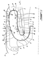
Referring to FIG. 4, the outer liner 26 is shown as being divided in three regions, namely region A located in primary section 40 and regions B and B′ located in downstream section 42, while the inner liner 24 is shown as being divided in two regions, namely region C located in the primary section 40 and region D located in the downstream section 42. The preferred relationship between the hole densities in these different regions is thus defined as:
n A + C n B + B + D 1
Where nA+C is the mean hole density over regions A and C (i.e. the primary section 40) and nB+B′+D is the mean hole density over regions B, B′ and D (i.e. the downstream section 42). As mentioned above, the maximum value for the density of the effusion holes 46 a,c defined in the primary section 40 (i.e. nA+C) is determined based on conditions producing a quenching of the combustion products near the combustor inner surfaces 32, 34 which would produce engine starting problems.
Moreover, the geometry of the effusion holes 46 a,b,c,d defined in each portion of the combustor 16 being considered (e.g. entire combustor 16 or part or all of the section(s) 40, 42) determines a discharge coefficient Cd for that portion. Each discharge coefficient Cd has a value between 0 (total blockage) and 1 (fully open). Each discharge coefficient Cd depends on the approach velocity of the airflow but also on flow blockage and restriction, i.e. the number, size and shape of the corresponding effusion holes 46 a,b,c,d (e.g. l/d where l is the length of the hole and d is the mean diameter, the length l being influenced by the projected angles θ, β). Each discharge coefficient Cd thus defines an effective open area ACd for the considered portion of the combustor 16 which is simply defined as:
ACd=A combustor *Cd
The effective open area ACd is thus related to the dynamic flow of the air through the effusion holes 46 a,b,c,d, and is used to calculate the combustor pressure drop AP across the combustor wall 24, 26 according to the following:
ACd = m * 2 ρ Δ P
where m is the air mass flow rate and ρ is the air density.
The shift of phase between noise from the compressor 14 and noise from the combustor 16 mentioned above is illustrated by a time delay Tdelay imposed on the low frequency vibrations generated by the compressor 14 with respect to the noise generated by the combustion process in the combustor 16. This time delay Tdelay is imposed by the deflection of the air entering the angled effusion holes 46 a,b,c,d, along two directions (projected angles β,θ). The double angle (β,θ) of the effusion holes 46 a,b,c,d shifts the noise from the compressor 14 along two directions which reduces the likelihood that it will be coupled with the noise from the combustor 16. Accordingly, the time delay Tdelay produces a decoupling effect on the noise from the compressor 14 and the combustor 16, thus further reducing the noise emissions of the engine 10.
Experiments have shown that the time delay Tdelay producing that decoupling effect is a function of the following parameters:
T delay =f[(x/d),(y/d),ΔP local, (θ/β)]
where x is the streamwise distance between adjacent effusion holes 46 a,b,c,d (shown in FIGS. 3A-3B), y is the spanwise distance between adjacent effusion holes 46 a,b,c,d (shown in FIGS. 3A-3B), d is the diameter of the effusion holes 46 a,b,c,d, ΔPlocal is the pressure differential across the combustor liner 24, 26 for the combustor portion considered (which is a function of ACd as described above), β is the projected angle of the hole direction 48 a,b,c,d to the corresponding outer surface 28, 30 and θ is the projected angle of the hole direction 48 a,b,c,d to the respective radial plane 50.
The decoupling time delay Tdelay is specific for each section 40, 42 of the combustor 16. However, as explained above, as most of the reaction between fuel/air happens in the primary section 40 where the majority of the heat is released, the decoupling time delay Tdelay corresponding to primary section 40, where the combustion process is initiated and the flame front stabilises, is the one that is preferably controlled.
Thus, the angle ratio θ/β is mainly responsible for creating the time delay Tdelay, which produces the frequency phase shift causing the decoupling action between the noise of the compressor 14 and of the combustor 16. The decoupling time delay Tdelay is also a function of the geometrical arrangement of the combustor holes (x,y,d), and of the pressure drop (ΔPlocal) across the combustor liners 24, 26 which is a measure of the intensity of the turbulence of the airflow and which is related to the geometry of the effusion holes through its relation to the effective open area ACd, as described above.
Accordingly, the exact size and configuration of the effusion holes 46 a,b,c,d producing the optimal noise reduction depends on many factors, including engine design conditions and application. For a specific engine and combustor geometry, the hole density (distances x,y) and hole diameter d are selected according to one or both the desired decoupling time delay Tdelay and the desired attenuated frequencies fa, particularly in the primary section 40 as detailed above. The projected angles β,θ are also selected according to the desired decoupling time delay Tdelay as detailed above. The geometry (density, size, angles) of the effusion holes 46 a,b,c,d is thus determined according to the desired decoupling time delay Tdelay and attenuated frequencies fa.
Experimental work is used to determine the most effective effusion hole pattern for a given engine 10. The noise emissions of the engine 10 are measured, for example by using a number of pressure transducers (PCB probes) installed on various parts of the engine 10. These PCB probes include straight lead-tube (approximately 10″) between the measurement location and the probe as well as an approximately 100 ft long closed-end wave-guide. All connected tubes are of the same internal diameter corresponding to the PCB probe diameter. Microphones are also installed outside the engine 10 at two different locations to measure the frequency radiated by the compressor 14 and the resultant frequency ranges in the turbine section 18 and/or the engine exhaust, such as to provide a comparison with the PCB probes measurement. Through the PCB probes and microphones, the frequency ranges generated and/or imposed by various components of the engine 10 is determined, and the source of attenuation of the frequencies is differentiated, whether inside or outside the combustor 16. A multi-channels recording system can be utilised to allow for real time data visualization. The frequency response of the PCB probes and microphones (Phase and Amplitude) is determined.
Once the frequency characteristics of the engine are known, the transparency coefficient τc (through the size and density of the effusion holes 46 a,b,c,d) and the angles β, θ are manipulated as detailed above to achieve the required sound attenuation and noise reduction for the specific size and shape of a particular combustor 16.
The double orientation effusion holes 46 a,b,c,d thus produce a noise attenuation effect on the engine 10 by producing a shift of phase between the noise from the compressor 14 and the noise from the combustor 16 as well as by reducing the amplitude of the combustor noise. An increased density of effusion holes 46 a,c in the primary section 40 allow for an increased noise attenuation effect in the primary section 40, which is more susceptible to both generate and amplify noises having a frequency requiring attenuation. The noise attenuation of low frequency ranges brought by the double orientation effusion holes 46 a,b,c,d allows for a reduction of the far field noise emission level of the engine 10, especially in cases where the engine 10 is an APU.
The above description is meant to be exemplary only, and one skilled in the art will recognize that changes may be made to the embodiments described without department from the scope of the invention disclosed. Other modifications which fall within the scope of the present invention will be apparent to those skilled in the art, in light of a review of this disclosure, and such modifications are intended to fall within the appended claims.

Claims (7)

1. A combustor for a gas turbine engine, the combustor comprising inner and outer liners defining an annular combustion chamber therebetween and joined by a combustor dome, the combustion chamber having a primary section adapted to receive a plurality of fuel nozzles and a secondary section defined downstream of the primary section, the inner and outer liners having a plurality of angled effusion holes defined therethrough in the primary and secondary sections, at least some of the effusion holes in the primary section being located between the fuel nozzles and the combustor dome, wherein a diameter of the effusion holes defined in the primary section is smaller than a diameter of all the effusion holes defined in the secondary section, each of the effusion holes being defined through a corresponding one of the liners at a first non-zero angle with respect to a surface of the corresponding one of the liners and at a second non-zero angle with respect to a corresponding radial plane extending radially from a central axis of the combustor, a density of the effusion holes defined in the primary section being greater than a density of the effusion holes defined in the secondary section.
2. The combustor as defined in claim 1, wherein the first angle has a value of between about 20 and 30 degrees.
3. The combustor as defined in claim 1, wherein a projection of the second angle on an outer surface of the corresponding one of the inner and outer liners has a value of between about 30 and 90 degrees.
4. The combustor as defined in claim 3, wherein the projection of the second angle has a value of approximately 45 degrees.
5. The combustor as defined in claim 1, wherein the diameter of the effusion holes defined in the primary section is approximately 0.020 inches.
6. The combustor as defined in claim 1, wherein the diameter of the effusion holes defined in the secondary section is approximately 0.030 inches.
7. The combustor as defined in claim 1, wherein each of the effusion holes has a hole direction defined along a central axis thereof and toward the combustion chamber, the hole direction of each of the effusion holes having a tangential component defined tangentially to a corresponding one of the inner and outer liners and perpendicularly to the central axis of the combustor, the tangential component of all of the effusion holes corresponding to a same rotational direction with respect to the central axis of the combustor.
US11/441,225 2006-05-26 2006-05-26 Noise reducing combustor Active 2029-03-29 US7856830B2 (en)

Priority Applications (2)

Application Number Priority Date Filing Date Title
US11/441,225 US7856830B2 (en) 2006-05-26 2006-05-26 Noise reducing combustor
CA2587058A CA2587058C (en) 2006-05-26 2007-05-02 Noise reducing combustor

Applications Claiming Priority (1)

Application Number Priority Date Filing Date Title
US11/441,225 US7856830B2 (en) 2006-05-26 2006-05-26 Noise reducing combustor

Publications (2)

Publication Number Publication Date
US20070271926A1 US20070271926A1 (en) 2007-11-29
US7856830B2 true US7856830B2 (en) 2010-12-28

Family

ID=38748248

Family Applications (1)

Application Number Title Priority Date Filing Date
US11/441,225 Active 2029-03-29 US7856830B2 (en) 2006-05-26 2006-05-26 Noise reducing combustor

Country Status (2)

Country Link
US (1) US7856830B2 (en)
CA (1) CA2587058C (en)

Cited By (15)

* Cited by examiner, † Cited by third party
Publication number Priority date Publication date Assignee Title
US20100186411A1 (en) * 2007-10-19 2010-07-29 Mitsubishi Heavy Industries, Ltd. Gas turbine
US20120125006A1 (en) * 2009-11-10 2012-05-24 Mitsubishi Heavy Industries, Ltd. Gas turbine combustor and gas turbine
US20130180257A1 (en) * 2012-01-18 2013-07-18 Honza Stastny Combustor for gas turbine engine
CN104204679A (en) * 2012-03-27 2014-12-10 西门子公司 An improved hole arrangement of liners of a combustion chamber of a gas turbine engine with low combustion dynamics and emissions
US9052111B2 (en) 2012-06-22 2015-06-09 United Technologies Corporation Turbine engine combustor wall with non-uniform distribution of effusion apertures
US9410447B2 (en) 2012-07-30 2016-08-09 United Technologies Corporation Forward compartment service system for a geared architecture gas turbine engine
US10260643B2 (en) 2014-12-02 2019-04-16 United Technologies Corporation Bleed valve resonator drain
US10359194B2 (en) 2014-08-26 2019-07-23 Siemens Energy, Inc. Film cooling hole arrangement for acoustic resonators in gas turbine engines
US10415480B2 (en) 2017-04-13 2019-09-17 General Electric Company Gas turbine engine fuel manifold damper and method of dynamics attenuation
US10724739B2 (en) 2017-03-24 2020-07-28 General Electric Company Combustor acoustic damping structure
US11149948B2 (en) 2017-08-21 2021-10-19 General Electric Company Fuel nozzle with angled main injection ports and radial main injection ports
US11156162B2 (en) 2018-05-23 2021-10-26 General Electric Company Fluid manifold damper for gas turbine engine
US11221143B2 (en) 2018-01-30 2022-01-11 General Electric Company Combustor and method of operation for improved emissions and durability
US11313560B2 (en) 2018-07-18 2022-04-26 General Electric Company Combustor assembly for a heat engine
US11506125B2 (en) 2018-08-01 2022-11-22 General Electric Company Fluid manifold assembly for gas turbine engine

Families Citing this family (14)

* Cited by examiner, † Cited by third party
Publication number Priority date Publication date Assignee Title
US7628020B2 (en) * 2006-05-26 2009-12-08 Pratt & Whitney Canada Cororation Combustor with improved swirl
US8104288B2 (en) * 2008-09-25 2012-01-31 Honeywell International Inc. Effusion cooling techniques for combustors in engine assemblies
US8640464B2 (en) * 2009-02-23 2014-02-04 Williams International Co., L.L.C. Combustion system
US9541292B2 (en) 2013-03-12 2017-01-10 Pratt & Whitney Canada Corp. Combustor for gas turbine engine
US9958161B2 (en) 2013-03-12 2018-05-01 Pratt & Whitney Canada Corp. Combustor for gas turbine engine
US9127843B2 (en) 2013-03-12 2015-09-08 Pratt & Whitney Canada Corp. Combustor for gas turbine engine
US9366187B2 (en) * 2013-03-12 2016-06-14 Pratt & Whitney Canada Corp. Slinger combustor
US9228747B2 (en) * 2013-03-12 2016-01-05 Pratt & Whitney Canada Corp. Combustor for gas turbine engine
FR3021097B1 (en) * 2014-05-15 2020-05-08 Safran Power Units REVERSE FLOW COMBUSTION CHAMBER COMPRISING AN OPTIMIZED ELBOW WALL
US9429323B2 (en) * 2014-05-15 2016-08-30 General Electric Technology Gmbh Combustion liner with bias effusion cooling
FR3037107B1 (en) * 2015-06-03 2019-11-15 Safran Aircraft Engines ANNULAR ROOM OF COMBUSTION CHAMBER WITH OPTIMIZED COOLING
US10337736B2 (en) * 2015-07-24 2019-07-02 Pratt & Whitney Canada Corp. Gas turbine engine combustor and method of forming same
US10684014B2 (en) * 2016-08-04 2020-06-16 Raytheon Technologies Corporation Combustor panel for gas turbine engine
EP3434980B1 (en) * 2017-07-25 2021-03-17 Ge Avio S.r.l. Reverse flow combustor

Citations (28)

* Cited by examiner, † Cited by third party
Publication number Priority date Publication date Assignee Title
US2654219A (en) 1950-09-04 1953-10-06 Bbc Brown Boveri & Cie Metal combustion chamber
US4422300A (en) 1981-12-14 1983-12-27 United Technologies Corporation Prestressed combustor liner for gas turbine engine
US4695247A (en) 1985-04-05 1987-09-22 Director-General Of The Agency Of Industrial Science & Technology Combustor of gas turbine
US5184455A (en) 1991-07-09 1993-02-09 The United States Of America As Represented By The Secretary Of The Air Force Ceramic blanket augmentor liner
US5216886A (en) 1991-08-14 1993-06-08 The United States Of America As Represented By The Secretary Of The Air Force Segmented cell wall liner for a combustion chamber
US5241827A (en) * 1991-05-03 1993-09-07 General Electric Company Multi-hole film cooled combuster linear with differential cooling
US5435139A (en) 1991-03-22 1995-07-25 Rolls-Royce Plc Removable combustor liner for gas turbine engine combustor
US5528904A (en) 1994-02-28 1996-06-25 Jones; Charles R. Coated hot gas duct liner
US5590531A (en) * 1993-12-22 1997-01-07 Societe National D'etdue Et De Construction De Moteurs D'aviation S.N.E.C.M.A. Perforated wall for a gas turbine engine
US5598697A (en) 1994-07-27 1997-02-04 Societe Nationale D'etude Et De Construction De Moteurs D'aviation S.N.E.C.M.A. Double wall construction for a gas turbine combustion chamber
US5687572A (en) 1992-11-02 1997-11-18 Alliedsignal Inc. Thin wall combustor with backside impingement cooling
US5758504A (en) 1996-08-05 1998-06-02 Solar Turbines Incorporated Impingement/effusion cooled combustor liner
US6105371A (en) * 1997-01-16 2000-08-22 Societe Nationale D'etude Et De Construction De Moteurs D'aviation "Snecma" Control of cooling flows for high-temperature combustion chambers having increased permeability in the downstream direction
US6282905B1 (en) 1998-11-12 2001-09-04 Mitsubishi Heavy Industries, Ltd. Gas turbine combustor cooling structure
US6330791B1 (en) 1999-01-22 2001-12-18 Alzeta Corporation Burner for operating gas turbines with minimal NOx emissions
US6351947B1 (en) 2000-04-04 2002-03-05 Abb Alstom Power (Schweiz) Combustion chamber for a gas turbine
US6513331B1 (en) * 2001-08-21 2003-02-04 General Electric Company Preferential multihole combustor liner
US6530221B1 (en) 2000-09-21 2003-03-11 Siemens Westinghouse Power Corporation Modular resonators for suppressing combustion instabilities in gas turbine power plants
US6546731B2 (en) 1999-12-01 2003-04-15 Abb Alstom Power Uk Ltd. Combustion chamber for a gas turbine engine
US6640544B2 (en) 2000-12-06 2003-11-04 Mitsubishi Heavy Industries, Ltd. Gas turbine combustor, gas turbine, and jet engine
US6698206B2 (en) 1999-12-16 2004-03-02 Rolls-Royce Plc Combustion chamber
US20040060295A1 (en) 2001-04-19 2004-04-01 Mitsubishi Heavy Industries, Ltd. Gas turbine combustor
US20040211188A1 (en) * 2003-04-28 2004-10-28 Hisham Alkabie Noise reducing combustor
US6955053B1 (en) * 2002-07-01 2005-10-18 Hamilton Sundstrand Corporation Pyrospin combuster
US20060042263A1 (en) 2004-08-27 2006-03-02 Pratt & Whitney Canada Corp. Combustor and method
US20060042271A1 (en) 2004-08-27 2006-03-02 Pratt & Whitney Canada Corp. Combustor and method of providing
US20060196188A1 (en) * 2005-03-01 2006-09-07 United Technologies Corporation Combustor cooling hole pattern
US7546737B2 (en) * 2006-01-24 2009-06-16 Honeywell International Inc. Segmented effusion cooled gas turbine engine combustor

Family Cites Families (2)

* Cited by examiner, † Cited by third party
Publication number Priority date Publication date Assignee Title
US5218886A (en) * 1989-03-03 1993-06-15 Sauer Inc. Hydrostatic transmission center section
US20060042663A1 (en) * 2004-08-25 2006-03-02 Baker Hughes Incorporated Method for removing iron deposits from within closed loop systems

Patent Citations (29)

* Cited by examiner, † Cited by third party
Publication number Priority date Publication date Assignee Title
US2654219A (en) 1950-09-04 1953-10-06 Bbc Brown Boveri & Cie Metal combustion chamber
US4422300A (en) 1981-12-14 1983-12-27 United Technologies Corporation Prestressed combustor liner for gas turbine engine
US4695247A (en) 1985-04-05 1987-09-22 Director-General Of The Agency Of Industrial Science & Technology Combustor of gas turbine
US5435139A (en) 1991-03-22 1995-07-25 Rolls-Royce Plc Removable combustor liner for gas turbine engine combustor
US5241827A (en) * 1991-05-03 1993-09-07 General Electric Company Multi-hole film cooled combuster linear with differential cooling
US5184455A (en) 1991-07-09 1993-02-09 The United States Of America As Represented By The Secretary Of The Air Force Ceramic blanket augmentor liner
US5216886A (en) 1991-08-14 1993-06-08 The United States Of America As Represented By The Secretary Of The Air Force Segmented cell wall liner for a combustion chamber
US5687572A (en) 1992-11-02 1997-11-18 Alliedsignal Inc. Thin wall combustor with backside impingement cooling
US5590531A (en) * 1993-12-22 1997-01-07 Societe National D'etdue Et De Construction De Moteurs D'aviation S.N.E.C.M.A. Perforated wall for a gas turbine engine
US5528904A (en) 1994-02-28 1996-06-25 Jones; Charles R. Coated hot gas duct liner
US5598697A (en) 1994-07-27 1997-02-04 Societe Nationale D'etude Et De Construction De Moteurs D'aviation S.N.E.C.M.A. Double wall construction for a gas turbine combustion chamber
US5758504A (en) 1996-08-05 1998-06-02 Solar Turbines Incorporated Impingement/effusion cooled combustor liner
US6105371A (en) * 1997-01-16 2000-08-22 Societe Nationale D'etude Et De Construction De Moteurs D'aviation "Snecma" Control of cooling flows for high-temperature combustion chambers having increased permeability in the downstream direction
US6282905B1 (en) 1998-11-12 2001-09-04 Mitsubishi Heavy Industries, Ltd. Gas turbine combustor cooling structure
US6330791B1 (en) 1999-01-22 2001-12-18 Alzeta Corporation Burner for operating gas turbines with minimal NOx emissions
US6546731B2 (en) 1999-12-01 2003-04-15 Abb Alstom Power Uk Ltd. Combustion chamber for a gas turbine engine
US6698206B2 (en) 1999-12-16 2004-03-02 Rolls-Royce Plc Combustion chamber
US6351947B1 (en) 2000-04-04 2002-03-05 Abb Alstom Power (Schweiz) Combustion chamber for a gas turbine
US6530221B1 (en) 2000-09-21 2003-03-11 Siemens Westinghouse Power Corporation Modular resonators for suppressing combustion instabilities in gas turbine power plants
US6640544B2 (en) 2000-12-06 2003-11-04 Mitsubishi Heavy Industries, Ltd. Gas turbine combustor, gas turbine, and jet engine
US20040060295A1 (en) 2001-04-19 2004-04-01 Mitsubishi Heavy Industries, Ltd. Gas turbine combustor
US6513331B1 (en) * 2001-08-21 2003-02-04 General Electric Company Preferential multihole combustor liner
US6955053B1 (en) * 2002-07-01 2005-10-18 Hamilton Sundstrand Corporation Pyrospin combuster
US20040211188A1 (en) * 2003-04-28 2004-10-28 Hisham Alkabie Noise reducing combustor
US6964170B2 (en) 2003-04-28 2005-11-15 Pratt & Whitney Canada Corp. Noise reducing combustor
US20060042263A1 (en) 2004-08-27 2006-03-02 Pratt & Whitney Canada Corp. Combustor and method
US20060042271A1 (en) 2004-08-27 2006-03-02 Pratt & Whitney Canada Corp. Combustor and method of providing
US20060196188A1 (en) * 2005-03-01 2006-09-07 United Technologies Corporation Combustor cooling hole pattern
US7546737B2 (en) * 2006-01-24 2009-06-16 Honeywell International Inc. Segmented effusion cooled gas turbine engine combustor

Cited By (19)

* Cited by examiner, † Cited by third party
Publication number Priority date Publication date Assignee Title
US8904794B2 (en) * 2007-10-19 2014-12-09 Mitsubishi Heavy Industries, Ltd. Gas turbine having a combustion oscillation suppressing device
US20100186411A1 (en) * 2007-10-19 2010-07-29 Mitsubishi Heavy Industries, Ltd. Gas turbine
US20120125006A1 (en) * 2009-11-10 2012-05-24 Mitsubishi Heavy Industries, Ltd. Gas turbine combustor and gas turbine
US8950190B2 (en) * 2009-11-10 2015-02-10 Mitsubishi Heavy Industries, Ltd. Gas turbine combustor having contraction member on inner wall surface
US9513008B2 (en) 2012-01-18 2016-12-06 Pratt & Whitney Canada Corp. Combustor for gas turbine engine
US20130180257A1 (en) * 2012-01-18 2013-07-18 Honza Stastny Combustor for gas turbine engine
US9134028B2 (en) * 2012-01-18 2015-09-15 Pratt & Whitney Canada Corp. Combustor for gas turbine engine
CN104204679A (en) * 2012-03-27 2014-12-10 西门子公司 An improved hole arrangement of liners of a combustion chamber of a gas turbine engine with low combustion dynamics and emissions
US9052111B2 (en) 2012-06-22 2015-06-09 United Technologies Corporation Turbine engine combustor wall with non-uniform distribution of effusion apertures
US9410447B2 (en) 2012-07-30 2016-08-09 United Technologies Corporation Forward compartment service system for a geared architecture gas turbine engine
US10359194B2 (en) 2014-08-26 2019-07-23 Siemens Energy, Inc. Film cooling hole arrangement for acoustic resonators in gas turbine engines
US10260643B2 (en) 2014-12-02 2019-04-16 United Technologies Corporation Bleed valve resonator drain
US10724739B2 (en) 2017-03-24 2020-07-28 General Electric Company Combustor acoustic damping structure
US10415480B2 (en) 2017-04-13 2019-09-17 General Electric Company Gas turbine engine fuel manifold damper and method of dynamics attenuation
US11149948B2 (en) 2017-08-21 2021-10-19 General Electric Company Fuel nozzle with angled main injection ports and radial main injection ports
US11221143B2 (en) 2018-01-30 2022-01-11 General Electric Company Combustor and method of operation for improved emissions and durability
US11156162B2 (en) 2018-05-23 2021-10-26 General Electric Company Fluid manifold damper for gas turbine engine
US11313560B2 (en) 2018-07-18 2022-04-26 General Electric Company Combustor assembly for a heat engine
US11506125B2 (en) 2018-08-01 2022-11-22 General Electric Company Fluid manifold assembly for gas turbine engine

Also Published As

Publication number Publication date
CA2587058C (en) 2012-06-19
US20070271926A1 (en) 2007-11-29
CA2587058A1 (en) 2007-11-26

Similar Documents

Publication Publication Date Title
US7856830B2 (en) Noise reducing combustor
US6981358B2 (en) Reheat combustion system for a gas turbine
JP6059902B2 (en) Sound damping device used in gas turbine engine
US6688109B2 (en) Turbine engine burner
EP1108957B1 (en) A combustion chamber
US6732527B2 (en) Combustion chamber
US6351947B1 (en) Combustion chamber for a gas turbine
US8336312B2 (en) Attenuation of combustion dynamics using a Herschel-Quincke filter
JP2006524791A (en) Noise suppression combustor
EP2116770B1 (en) Combustor dynamic attenuation and cooling arrangement
US7954328B2 (en) Flame holder for minimizing combustor screech
JP2010019544A (en) Combustor structure
US6490864B1 (en) Burner with damper for attenuating thermo acoustic instabilities
KR20170020903A (en) Oxygen-fuel burner with cavity-actuated mixing
US7065971B2 (en) Device for efficient usage of cooling air for acoustic damping of combustion chamber pulsations
US6449951B1 (en) Combustion device for generating hot gases
Krüger et al. Prediction and measurement of thermoacoustic improvements in gas turbines with annular combustion systems
Andreini et al. Experimental investigation on effusion liner geometries for aero-engine combustors: evaluation of global acoustic parameters
Paschereit et al. The effectiveness of passive combustion control methods
US6615587B1 (en) Combustion device and method for burning a fuel
Balakrishnan et al. Pipe jet noise reduction using co-axial swirl pipe
Weber et al. Characterization of dynamics of unstable fuel-rich flame
Macquisten et al. Passive damper LP tests for controlling combustion instability
JP7257215B2 (en) Acoustic dampers, combustors and gas turbines
Allison et al. Investigation of dimethyl ether combustion instabilities in a partially-premixed gas turbine model combustor using high-speed laser diagnostics

Legal Events

Date Code Title Description
AS Assignment

Owner name: PRATT & WHITNEY CANADA CORP., CANADA

Free format text: ASSIGNMENT OF ASSIGNORS INTEREST;ASSIGNOR:ALKABIE, HISHAM;REEL/FRAME:017918/0107

Effective date: 20060523

STCF Information on status: patent grant

Free format text: PATENTED CASE

FPAY Fee payment

Year of fee payment: 4

MAFP Maintenance fee payment

Free format text: PAYMENT OF MAINTENANCE FEE, 8TH YEAR, LARGE ENTITY (ORIGINAL EVENT CODE: M1552)

Year of fee payment: 8

MAFP Maintenance fee payment

Free format text: PAYMENT OF MAINTENANCE FEE, 12TH YEAR, LARGE ENTITY (ORIGINAL EVENT CODE: M1553); ENTITY STATUS OF PATENT OWNER: LARGE ENTITY

Year of fee payment: 12