US7863828B2 - Power supply DC voltage offset detector - Google Patents
Power supply DC voltage offset detector Download PDFInfo
- Publication number
- US7863828B2 US7863828B2 US11/967,277 US96727707A US7863828B2 US 7863828 B2 US7863828 B2 US 7863828B2 US 96727707 A US96727707 A US 96727707A US 7863828 B2 US7863828 B2 US 7863828B2
- Authority
- US
- United States
- Prior art keywords
- ripple component
- output voltage
- offset
- ripple
- reference voltage
- Prior art date
- Legal status (The legal status is an assumption and is not a legal conclusion. Google has not performed a legal analysis and makes no representation as to the accuracy of the status listed.)
- Active, expires
Links
Images


Classifications
-
- H—ELECTRICITY
- H02—GENERATION; CONVERSION OR DISTRIBUTION OF ELECTRIC POWER
- H02M—APPARATUS FOR CONVERSION BETWEEN AC AND AC, BETWEEN AC AND DC, OR BETWEEN DC AND DC, AND FOR USE WITH MAINS OR SIMILAR POWER SUPPLY SYSTEMS; CONVERSION OF DC OR AC INPUT POWER INTO SURGE OUTPUT POWER; CONTROL OR REGULATION THEREOF
- H02M1/00—Details of apparatus for conversion
- H02M1/42—Circuits or arrangements for compensating for or adjusting power factor in converters or inverters
- H02M1/4208—Arrangements for improving power factor of AC input
- H02M1/4225—Arrangements for improving power factor of AC input using a non-isolated boost converter
-
- H—ELECTRICITY
- H03—ELECTRONIC CIRCUITRY
- H03M—CODING; DECODING; CODE CONVERSION IN GENERAL
- H03M3/00—Conversion of analogue values to or from differential modulation
- H03M3/30—Delta-sigma modulation
- H03M3/458—Analogue/digital converters using delta-sigma modulation as an intermediate step
- H03M3/476—Non-linear conversion systems
-
- Y—GENERAL TAGGING OF NEW TECHNOLOGICAL DEVELOPMENTS; GENERAL TAGGING OF CROSS-SECTIONAL TECHNOLOGIES SPANNING OVER SEVERAL SECTIONS OF THE IPC; TECHNICAL SUBJECTS COVERED BY FORMER USPC CROSS-REFERENCE ART COLLECTIONS [XRACs] AND DIGESTS
- Y02—TECHNOLOGIES OR APPLICATIONS FOR MITIGATION OR ADAPTATION AGAINST CLIMATE CHANGE
- Y02B—CLIMATE CHANGE MITIGATION TECHNOLOGIES RELATED TO BUILDINGS, e.g. HOUSING, HOUSE APPLIANCES OR RELATED END-USER APPLICATIONS
- Y02B70/00—Technologies for an efficient end-user side electric power management and consumption
- Y02B70/10—Technologies improving the efficiency by using switched-mode power supplies [SMPS], i.e. efficient power electronics conversion e.g. power factor correction or reduction of losses in power supplies or efficient standby modes
-
- Y—GENERAL TAGGING OF NEW TECHNOLOGICAL DEVELOPMENTS; GENERAL TAGGING OF CROSS-SECTIONAL TECHNOLOGIES SPANNING OVER SEVERAL SECTIONS OF THE IPC; TECHNICAL SUBJECTS COVERED BY FORMER USPC CROSS-REFERENCE ART COLLECTIONS [XRACs] AND DIGESTS
- Y02—TECHNOLOGIES OR APPLICATIONS FOR MITIGATION OR ADAPTATION AGAINST CLIMATE CHANGE
- Y02P—CLIMATE CHANGE MITIGATION TECHNOLOGIES IN THE PRODUCTION OR PROCESSING OF GOODS
- Y02P80/00—Climate change mitigation technologies for sector-wide applications
- Y02P80/10—Efficient use of energy, e.g. using compressed air or pressurized fluid as energy carrier
Definitions
- the present invention relates in general to the field of signal processing, and, more specifically, to a power factor correction controller with a power supply DC offset detector.
- FIG. 1 depicts a power control system 100 , which includes a switching power converter 102 .
- the switching power converter 102 performs power factor correction and provides constant voltage power to load 112 .
- Voltage source 101 supplies an alternating current (AC) input voltage V in (t) to a full, diode bridge rectifier 103 .
- the voltage source 101 is, for example, a public utility, and the AC voltage V in (t) is, for example, a 60 Hz/110 V line voltage in the United States of America or a 50 Hz/220 V line voltage in Europe.
- the rectifier 103 rectifies the input voltage V in (t) and supplies a rectified, time-varying, line input voltage V x (t) to the switching power converter.
- the switching power converter 102 includes power factor correction (PFC) stage 124 and driver stage 126 .
- the PFC stage 124 is controlled by switch 108 and provides power factor correction.
- the driver stage 126 is also controlled by switch 108 and regulates the transfer of energy from the line input voltage V x (t) through inductor 110 to capacitor 106 .
- the inductor current i L ramps ‘up’ when the switch 108 conducts, i.e. is “ON”.
- the inductor current i L ramps down when switch 108 is nonconductive, i.e. is “OFF”, and supplies current i L to recharge capacitor 106 .
- the time period during which inductor current i L ramps down is commonly referred to as the “inductor flyback time”.
- the switching power converter 102 operates in discontinuous current mode, i.e. the inductor current i L ramp up time plus the inductor flyback time is less than the period of switch 108 .
- Capacitor 106 supplies stored energy to load 112 while the switch 108 conducts.
- the capacitor 106 is sufficiently large so as to maintain a substantially constant output voltage V c (t), as established by a power factor correction (PFC) and output voltage controller 114 (as discussed in more detail below).
- the output voltage V c (t) remains substantially constant during constant load conditions. However, as load conditions change, the output voltage V c (t) changes.
- the PFC and output voltage controller 114 responds to the changes in V c (t) and adjusts the control signal CS 0 to maintain a substantially constant output voltage as quickly as possible.
- the output voltage controller 114 includes a small capacitor 115 to filter any high frequency signals from the line input voltage V x (t).
- the power control system 100 also includes a PFC and output voltage controller 114 to control the switch 108 and, thus, control power factor correction and regulate output power of the switching power converter 102 .
- the goal of power factor correction technology is to make the switching power converter 102 appear resistive to the voltage source 101 .
- the PFC and output voltage controller 114 attempts to control the inductor current i L so that the average inductor current i L is linearly and directly related to the line input voltage V x (t). Prodi ⁇ , Compensator Design and Stability Assessment for Fast Voltage Loops of Power Factor Correction Rectifiers , IEEE Transactions on Power Electronics, Vol. 22, No. 5, September 2007, pp.
- PFC and output voltage controller 114 supplies a pulse width modified (PWM) control signal CS 0 to control the conductivity of switch 108 .
- PWM pulse width modified
- switch 108 is a field effect transistor (FET)
- control signal CS 0 is the gate voltage of switch 108 .
- the values of the pulse width and duty cycle of control signal CS 0 depend on two feedback signals, namely, the line input voltage V x (t) and the capacitor voltage/output voltage V c (t).
- Switching power converter 114 receives two feedback signals, the line input voltage V x (t) and the output voltage V c (t), via a wide bandwidth current loop 116 and a slower voltage loop 118 .
- the line input voltage V x (t) is sensed from node 120 between the diode rectifier and inductor 110 .
- the output voltage V c (t) is sensed from node 122 between diode 111 and load 112 .
- the current loop 116 operates at a frequency f c that is sufficient to allow the PFC and output controller 114 to respond to changes in the line input voltage V x (t) and cause the inductor current i L to track the line input voltage to provide power factor correction.
- the current loop frequency is generally set to a value between 20 kHz and 150 kHz.
- the voltage loop 118 operates at a much slower frequency f v , typically 10-20 Hz.
- the capacitor voltage V c (t) includes an AC component (sometimes referred to herein as a “ripple”) having a frequency equal to twice the frequency of input voltage V in (t), e.g. 120 Hz.
- the voltage loop 118 functions as a low pass filter to filter the ripple component.
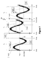
- FIG. 2 depicts an output voltage V c (t) versus time graph 200 .
- the output voltage V c (t) supplied by power control system 100 includes a direct current (DC) component, i.e. the DC offset for voltage V c (t), and an exemplary AC component, e.g. ripple 202 .
- Ripple 202 is generally triangular shaped. However, ripple 202 can be any waveform. Ripple 202 is depicted with a “dense” line because ripple 202 generally contains many high frequency noise perturbations. The noise is, for example, caused by noise across the inductor 110 and noise from load 112 .
- load 112 includes another switching power converter, and an inductor corresponding to inductor 110 can cause noise to appear at the output of switching power converter 102 .
- ripple 202 is generally not a ‘clean’ waveform, such as a sine wave. Rather, ripple 202 has, for example, a generally triangular shape with many noise perturbations.
- the DC offset for voltage V c (t) can change over time due to input power fluctuations and load power demand fluctuations.
- the PFC and output voltage controller 114 monitors the output voltage V c (t) and adjusts the control signal CS 0 to return the output voltage V c (t) to the desired value.
- the ripple 202 can adversely influence the determination of the control signal CS 0 by PFC and output voltage controller 114 .
- the voltage loop 118 operates at a much slower frequency f v , typically 10-20 Hz, than the line frequency f L .
- the voltage loop 118 functions as a low pass filter to filter out ripple 202 .
- operating at 10-20 Hz also slows the response of PFC and output voltage controller 114 to changes in the output voltage V c (t).
- FIG. 3 depicts a generalized representation of a power control system 300 described in Prodi ⁇ .
- the PFC and output voltage controller 302 of Prodi ⁇ includes an error generator 304 to determine an error signal e d (t).
- the error signal e d (t) represents a difference between the output voltage V c (t) and a reference voltage V REF .
- the reference voltage V REF is set to the desired value of output voltage V c (t).
- a comb filter 306 filters the error signal e d (t).
- the comb filter 306 has significant attenuation at equally spaced frequencies (referred to as “notches”) and has unity gain at other frequencies.
- the comb filter 306 automatically tunes the notches to match twice the line frequency f L and harmonics of the line frequency.
- the comb filter 306 generates a “ripple free” error signal e vf (t).
- Compensator 308 processes the filtered error signal and input voltage feedback signal V x (t) generates a compensator output signal.
- the pulse width modulator (PWM) 310 processes the compensator output signal to generate control signal CS 0 .
- the comb filter 306 notches should be accurate to precisely match the line frequency f L and harmonics thereof and avoid aliasing.
- an apparatus in one embodiment, includes a power supply output voltage direct current (DC) offset detector, wherein an output voltage of a power supply comprises a ripple component and a DC offset.
- the power supply output voltage DC offset detector includes a comparator to generate a comparison signal during a period of the ripple component, wherein the comparison signal represents a comparison between the ripple component and a reference voltage.
- the power supply output voltage DC offset detector also includes a processor, coupled to the comparator, configured to determine, based on the comparison signal, at least one of: (i) a first duration for which the ripple component is above the reference voltage and (ii) a second duration for which the ripple component is below the reference voltage.
- the power supply output voltage DC offset detector is further configured to use the first and second ripple component durations to determine the DC offset of the output voltage during the period of the ripple component.
- a method to determine a direct current (DC) offset of an output voltage of a power supply, wherein the output voltage comprises a periodic ripple component and a DC offset includes generating a comparison signal during a period of the ripple component, wherein the comparison signal represents a comparison between the ripple component and a reference voltage.
- the method further includes determining, based on the comparison signal, at least one of: (i) a first duration for which the ripple component is above the reference voltage and (ii) a second duration for which the ripple component is below the reference voltage.
- the method also includes using the first and second ripple component durations to determine the DC offset of the output voltage during the period of the ripple component.
- a sampling module to sample a power supply output voltage includes a comparator to generate a comparison signal during a period of a ripple component.
- the power supply output voltage includes a ripple component and a DC offset.
- the comparison signal represents a comparison between the ripple component and a reference voltage.
- the sampling module also includes a processor coupled to the comparator.
- the processor is configured to determine, based on the comparison signal, a duration for which the ripple component is above the reference voltage.
- the processor is further configured to use the duration for which the ripple component is above the reference voltage and the period of the ripple component to determine a sample of the output voltage during the period of the ripple component.
- a sampling module to sample a power supply output voltage includes a comparator to generate a comparison signal during a period of a ripple component.
- the power supply output voltage includes the ripple component and a DC offset.
- the comparison signal represents a comparison between the ripple component and a reference voltage.
- the sampling module also includes a processor coupled to the comparator.
- the processor is configured to determine, based on the comparison signal, a duration for which the ripple component is below the reference voltage.
- the processor is further configured to use the duration for which the ripple component is below the reference voltage and use the period of the ripple component to determine a sample of the output voltage during the period of the ripple component.
- FIG. 1 (labeled prior art) depicts a power control system.
- FIG. 2 (labeled prior art) depicts a power control system output voltage with an alternating current ripple component versus time graph.
- FIG. 3 (labeled prior art) depicts a power and control system with an output voltage feedback filter.
- FIG. 4 depicts one embodiment of a power system that includes a power supply and a DC offset determination system with a DC offset detector.
- FIG. 5 depicts a DC offset determination process.
- FIG. 6 depicts DC and ripple components of an output voltage feedback signal.
- FIG. 7 depicts a voltage versus time graph that highlights three exemplary periods of a ripple component of a power supply output voltage signal.
- FIG. 8 depicts ripple components near a reference voltage.
- FIG. 9 depicts one exemplary period of a ripple component of a power supply output voltage signal and a corresponding comparison signal of a DC offset value calculator.
- FIG. 10 depicts a DC offset determination system.
- FIG. 11 depicts one embodiment of a triangular wave representing a linear approximation of a ripple component of a power supply output voltage signal.
- FIG. 12 depicts a power control system having a sampling module with a DC offset detector.
- a power supply output voltage direct current (DC) offset detector determines a DC offset in a power supply output voltage signal, and the output voltage signal has a DC component and an alternating current (AC) “ripple” component.
- the DC offset detector determines the DC offset from an output voltage signal using a comparison between the output voltage signal and a reference voltage.
- the DC offset detector determines an ‘above’ duration for which the ripple is above the reference voltage, determines a ‘below’ duration for which the ripple is below the reference voltage, or both to determine the DC offset of the power supply output voltage signal.
- the DC offset detector uses the above and/or below duration(s) to determine the DC offset of the output voltage signal.
- the DC offset detector effectively samples the voltage signal at a sampling frequency equal to a frequency of the ripple and filters out the ripple from the output voltage signal to determine a sampled power supply output voltage effectively uninfluenced by the ripple.
- the duration ‘above’ and/or ‘below’ is determined in terms of a number of cycles in a clock signal of the DC detector.
- the DC offset detector determines a fraction of the total duration of a period of the ripple when the ripple is above the reference voltage and uses the fraction to determine the DC offset of the output voltage signal.
- the ripple frequency is twice a frequency of an input voltage supplied to the power supply.
- the DC offset detector provides the sampled output voltage signal to a PFC and output voltage controller, and the PFC and output voltage controller utilizes the sampled power supply voltage to determine a control signal to control a switching power converter.
- the durations of the ripple above and/or below the reference voltage can be measured in terms of clock cycles, time intervals, or any other duration measurement unit.
- FIG. 4 depicts one embodiment of a power system 400 that includes a power supply 402 and a DC offset determination system 404 with a DC offset detector 406 .
- the power supply 402 receives an AC input voltage V in (t) from voltage source 101 and supplies a power supply output voltage V OUT (t) to load 112 .
- the power supply output voltage V OUT (t) includes a DC offset component and a ripple 202 ( FIG. 6 ).
- the DC offset determination system 404 determines a discrete sampling signal V DCO (n), and the discrete sampling signal V DCO (n) represents a sample of a DC offset component of the power supply output voltage V OUT (t) substantially uninfluenced by ripple 202 .
- “n” is a marker having a value that represents a particular sample.
- the sampling frequency of the sampling signal V DCO (n) is the same as a frequency f R of ripple 202 .
- the ripple frequency f R equals twice the frequency of input voltage V in (t).
- the DC offset determination system 404 samples the power supply output voltage V OUT (t) at twice the line frequency f L of input voltage V in (t) and substantially eliminates any effect of the ripple 202 on the sampling signal V DCO (n).
- FIGS. 4-11 depict embodiments of systems and processes of determining the sampling signal V DCO (n).
- FIG. 5 depicts a DC offset determination process 500 .
- FIG. 6 depicts the DC and ripple components of one embodiment of the output voltage V OUT (t) together with a reference voltage V REF1 .
- FIG. 7 depicts a voltage versus time graph 700 that highlights three exemplary periods of ripple 202 in relation to the reference voltage V REF1 .
- FIG. 8 depicts exemplary ripple components 800 near the reference voltage V REF1 .
- FIG. 9 depicts one exemplary period 900 of ripple 202 and a corresponding comparison signal V A/B .
- FIG. 10 depicts an exemplary DC offset determination system 1000 to physically implement process 500 .
- FIG. 11 depicts one embodiment of triangular wave 1100 , and the triangular wave 1100 represents a linear approximation of ripple 202 .
- the DC offset determination system 404 determines the sampling signal V DCO (n) in accordance with DC offset determination process 500 .
- Process 500 repeats for each period of ripple 202 .
- one period T 0 of ripple 202 is between time 0 and time 1 ( FIG. 6 ). If ripple 202 is periodic, all periods of ripple 202 are equal.
- the DC offset determination process 500 uses a comparison between the output voltage V OUT (t) and the reference voltage V REF1 to determine the DC offset of power supply output voltage signal V OUT (t). Determining the DC offset of output voltage V OUT (t) also determines the DC offset of power supply output voltage V OUT (t).
- comparator 1002 In operation 502 , comparator 1002 generates a comparison signal V A/B .
- Comparison signal V A/B represents a comparison between reference voltage V REF1 and output voltage V OUT (t).
- Comparison signal V A/B changes states between logical “1” and a logical “0” based on an outcome of the comparison.
- the state changes of comparison signal V A/B also indicate whether output voltage V OUT (t) is transitioning above or below the reference voltage V REF1 .
- the reference voltage V REF1 is set so that the value of the reference voltage V REF1 is between the respective peaks V R (t)+ and V R (t) ⁇ of ripple 202 .
- the comparator 1002 generates a positive (logical 1) comparison signal V A/B when the output voltage V OUT (t) is above, i.e. greater than, the reference voltage V REF1 .
- the comparator 1002 generates a negative (logical 0) comparison signal V A/B when the output voltage V OUT (t) is below, i.e. less than, the reference voltage V REF1 .
- the state of comparison signal V A/B stays constant while the ripple 202 is above the reference voltage V REF1 and changes state when the ripple 202 transitions below the reference voltage V REF1 .
- the respective peaks V R (t)+ and V R (t) ⁇ of ripple 202 can be predetermined or measured by DC offset determination system 404 by determining the voltage fluctuation range of V OUT (t) under a constant load 112 .
- processor 1006 receives the comparison signal V A/B and determines, based on the comparison signal, at least one of: (i) a first duration for which the ripple component is above the reference voltage V REF1 and (ii) a second duration for which the ripple component is below the reference voltage V REF1 .
- the durations above the reference voltage V REF1 for periods T 0 and T 6 of ripple 202 have been respectively labeled “D ABOVE — 0 ” and “D ABOVE — 6 ”
- the durations below the reference voltage V REF1 for periods T 0 and T 6 have been respectively labeled “D BELOW — 0 ” and “D BELOW — 6 ” in FIG. 6 .
- the other periods of ripple 202 also have durations above and durations below the reference voltage V REF1 but are not specifically labeled to avoid obfuscating features in FIG. 6 .
- Graph 600 of FIG. 6 depicts the power supply output voltage V OUT (t) increasing between times 2 and 3 , decreasing between times 3 and 6 , and increasing between times 6 and 7 . Accordingly, the DC offset of power supply output voltage V OUT (t) (V OUT (t) DC offset) and the peak-to-peak ripple voltages V R (t)+ and V R (t) ⁇ also increase and decrease in unison. Thus, the relationship between ripple 202 and the reference voltage V REF1 changes as the power supply output voltage V OUT (t) changes over time.
- the voltage versus time graph 700 ( FIG. 7 ) highlights three exemplary periods T 0 , T 1 , and T 2 of ripple 202 in relation to the reference voltage V REF1 .
- the reference voltage V REF1 remains constant for an interval of time. In at least one embodiment, the reference voltage V REF1 remains constant during the operation of power control system 400 . In at least one embodiment, the reference voltage V REF1 increases if the duration of the output voltage V OUT (t) equals the period of ripple 202 and decreases if the duration of the output voltage V OUT (t) equals the period of ripple 202 . As the DC offset of output voltage V OUT (t) changes, the relationship between the reference voltage V REF1 and the output voltage V OUT (t) changes.
- the processor 1006 can take any of a variety of actions if the ripple 202 increases completely above or decreases completely below the reference voltage V REF1 .
- the processor 1006 can change the reference voltage V REF1 in the direction of ripple 202 as indicated by the comparison signal V A/B indication, i.e. higher if the comparison signal V A/B is logical “1” and lower if the comparison signal V A/B is logical “0”.
- the power supply 402 modifies the output voltage V OUT (t) until processor 1006 indicates that the reference voltage V REF1 is within the peak-to-peak voltages V R (t)+ to V R (t) ⁇ .
- the duration of ripple 202 above the reference voltage V REF1 is equal to the duration below the reference voltage V REF1 .
- the reference voltage V REF1 equals the DC offset of output voltage V OUT (t).
- the duration of ripple 202 above the reference voltage V REF1 is greater than the duration below the reference voltage V REF1 .
- the reference voltage V REF1 is less than DC offset of output voltage V OUT (t).
- the duration of ripple 202 above the reference voltage V REF1 is less than the duration below the reference voltage V REF1 .
- the reference voltage V REF1 is greater than DC voltage V OUT (t) DC offset.
- determining the difference between the reference voltage V REF1 and DC offset for voltage V OUT (t) allows DC offset determination system 404 to determine the DC offset for voltage V OUT (t) and, thus, sample output voltage V OUT (t) approximately uninfluenced by ripple 202 .
- FIG. 8 depicts exemplary waveform components 800 of ripple 202 near the reference voltage V REF1 .
- the waveform components 800 depict exemplary perturbations in ripple 202 .
- the comparison signal V A/B is a Near reference voltage V REF1 , ripple 202 crosses the reference voltage V REF1 multiple times.
- FIG. 9 depicts one exemplary period of ripple 202 and a corresponding comparison signal V A/B .
- the comparison signal V A/B changes states each time the ripple 202 crosses the reference voltage V REF1 . Because of the noise on the ripple 202 , as indicated by the exemplary waveform components 800 ( FIG. 8 ), when the ripple 202 is near the reference voltage V REF1 , the ripple 202 crosses the reference voltage frequently.
- the comparison signal V A/B crosses the reference voltage V A/B at the beginning of ripple 202 at and around time to, at and around time t 1 , and at the end of ripple 202 at and around time t 2 .
- the comparison signal V A/B changes logical states.
- the DC offset value calculator 1008 can determine the DC offset of output voltage V OUT (t) using either the duration of ripple 202 above the reference voltage V REF1 , the duration of ripple 202 below the reference voltage V REF1 , or both.
- the ripple 202 frequency f R equals twice the frequency f L of input voltage V in (t). Thus, if the frequency of input voltage V in (t) equals 60 Hz, the ripple frequency f R equals 120 Hz.
- DC offset value calculator 1008 determines both the duration of ripple 202 above the reference voltage V REF1 and the duration of ripple 202 below the reference voltage V REF1 , and, then determines the DC offset of output voltage V OUT (t).
- operation 504 utilizes DC offset determination system 1000 to determine the duration of ripple 202 above the reference voltage V REF1 during a period of ripple 202 .
- the DC offset determination system 1000 of FIG. 10 represents one embodiment of the DC offset determination system 404 of FIG. 4 .
- counter 1004 determines a number of clock cycles of clock signal CLK that occur while the comparison signal V A/B is logical “1”, indicating that ripple 202 is above the reference voltage V REF1 .
- Counter 1004 generates count signal CNT that, in at least one embodiment, represents the number of cycles that ripple 202 is above the reference voltage V REF1 , and, thus, represents the duration of ripple 202 above the reference voltage V REF1 .
- operation 504 utilizes DC offset determination system 1000 to determine the duration of ripple 202 below the reference voltage V REF1 during a period of ripple 202 .
- counter 1004 determines a number of clock cycles of clock signal CLK that occur while the comparison signal V A/B is logical “0”, indicating that ripple 202 is below the reference voltage V REF1 .
- Counter 1004 generates a count signal CNT that, in at least one embodiment, represents the number of cycles that ripple 202 is below the reference voltage V REF1 , and, thus, represents the duration of ripple 202 below the reference voltage V REF1 .
- operation 504 utilizes the DC offset determination system 1000 to determine both the duration of ripple 202 above and below the reference voltage V REF1 .
- the count signal CNT represents both the number of cycles the ripple 202 is above and below the reference voltage V REF1 .
- count signal CNT can be 2 separate signals, one representing the number of cycles the ripple 202 is above the reference voltage V REF1 and one representing the number of cycles below the reference voltage V REF1 .
- the clock frequency f CLK is set higher than the frequency of ripple 202 .
- the particular clock frequency f CLK is a matter of design choice and is, for example, set between 20 kHz and 150 kHz.
- the higher the clock frequency f CLK the more accurate the determination of the fraction of time that ripple 202 exceeds the reference voltage V REF1 .
- Setting the clock frequency f CLK higher than the highest frequency of exemplary ripple components 800 allows counter 1004 to accurately count the duration of ripple 202 near the reference voltage V REF1 .
- the DC offset determination system 1000 counts the number of clock cycles during which the ripple 202 is above, below, or both above and below the reference voltage V REF1 .
- the ripple 202 crosses the voltage reference V REF1 multiple times during a period of ripple 200 , and, in at least one embodiment, the counter 1004 counts all the cycles of clock signal CLK during which the comparison signal V A/B is a logical “1” to determine the time ripple 202 is above the reference voltage V REF1 .
- the counter 1004 counts all the cycles of clock signal CLK during which the comparison signal V A/B is logical “0” to determine the time ripple 202 is below the reference voltage V REF1 .
- FIG. 11 depicts one embodiment of triangular wave 1100 , and the triangular wave 1100 represents a linear approximation of ripple 202 corresponding to the three periods of ripple 202 depicted in a voltage versus time graph 700 .
- Triangular wave 1100 has peak-to-peak voltages of V R (t)+ to V R (t) ⁇ .
- DC offset value calculator 1008 can relatively easily and quickly determine the DC offset of power supply output voltage V OUT (t).
- Using a linear approximation of the ripple 202 such as a triangular wave approximation, can simplify the implementation of DC offset value calculator 1008 without significantly compromising accuracy.
- DC offset value calculator 1008 determines the fraction of the ripple 202 above the reference voltage V REF1 using a linear approximation of ripple 202 .
- DC offset calculator 1008 uses the triangular wave 1100 approximation of ripple 202 to determine an approximate DC offset voltage V OUT (t)′ in accordance with Equation [1]: DC Offset V OUT ( t ) ⁇ V REF1 +V R ( t ) + ⁇ (2 D ⁇ 1) Equation [1].
- DC Offset V OUT (t)′ represents the DC offset of output voltage V OUT (t).
- V REF represents the reference voltage against which the ripple 202 is compared.
- V R (t)+ represents the highest peak voltage of ripple 202 .
- the period of ripple 202 can be predetermined or can be determined by adding the above and below durations of ripple 202 with respect to the reference voltage V REF1 . In at least one embodiment, if the period 202 is known, the duration of ripple 202 below the reference voltage V REF1 does not need to be explicitly determined in operation 504 .
- both the duration of ripple 202 above and below the reference voltage V REF1 are used to determine the DC offset of output voltage V OUT (t) because the period of ripple 202 includes both the durations of ripple 202 above and below the reference voltage V REF1 .
- the power supply output voltage V OUT (t) is represented by an associated output voltage signal V OUT (t)′.
- the V OUT (t)′ represents the power supply output voltage V OUT (t) in a version amenable for determining the DC offset of the power supply output voltage.
- the output voltage signal V OUT (t)′ is a direct representation of the power supply output voltage V OUT (t), and, in at least one embodiment, the output voltage signal is derived from the power supply output voltage.
- the output voltage signal is scaled using, for example, a voltage divider or a variable current source as described in Melanson I and Melanson II. In at least one embodiment, the output voltage signal is scaled to a voltage that can be safely received by an integrated circuit.
- the output voltage signal V OUT (t)′ can be used in place of the output voltage V OUT (t) to determine the DC offset of the output voltage V OUT (t) in Equation [1]. Accordingly, determining the DC offset of the output voltage signal V OUT (t)′determines the DC offset of power supply output voltage V OUT (t). By determining the approximate DC offset V OUT (t)′, the contribution of ripple 202 to the power supply output voltage V OUT (t) is effectively removed.
- Equation [1] represents an exemplary process for calculating an estimated DC offset voltage V OUT (t)′. Many other processes can be used to estimate the DC offset voltage V OUT (t). Equation [1] can be modified to use the fraction of time ripple 202 that is below the reference voltage V REF . Equation [1] can be modified to accommodate different approximations of ripple 202 , such as a more complex nonlinear estimation of ripple 202 . Areas of the ripple 202 above and/or below the reference voltage V REF can also be used, and Equation [1] modified accordingly.
- the DC offset value calculator 1008 provides the sampling signal V DCO (n), which represents the DC offset of power supply output voltage V OUT (t).
- Each value of sampling signal V DCO (n) thus, represents a sample of power supply output voltage V OUT (t) with a sampling rate equal to the ripple frequency f R .
- Each value of sampling signal V DCO (n) is substantially uninfluenced by ripple 202 and is sufficient for many applications, such as power factor correction and output voltage regulation controllers.
- the sampling signal V DCO (n) represents the DC offset of the power supply output voltage V OUT (t).
- the sampling signal V DCO (n) can be used for any of a variety of purposes.
- the sampling signal V DCO (n) can be used as an input to display the DC component of the power supply output voltage V OUT (t).
- the sampling signal V DCO (n) can be used as feedback to a control system, and the control system controls one or more aspects (such as power factor correction and output voltage regulation) of the power supply 402 .
- FIG. 12 depicts a power control system 1200 that includes a PFC and output voltage controller 1202 to provide a power factor correction (PFC) and output voltage regulation control signal to switch 128 of switching power converter 1204 .
- the switching power converter 1204 includes a PFC stage 1208 and a driver stage 1210 .
- the particular configuration of PFC stage 1208 and driver stage 1210 is a design choice.
- PFC stage 124 represents one embodiment of PFC stage 1208
- driver stage 126 represents one embodiment of driver stage 1210 .
- control signal CS 1 controls conduction of switch 108
- the period and duty cycle of control signal CS 1 controls power factor correction and output voltage regulation of switching power converter 1204 .
- the PFC and output voltage controller 1202 includes a PFC and controller module 1206 to determine control signal CS 1 .
- the determination of control signal CS 1 is based on feedback data V FB(s) representing the input voltage V x (t) and the power supply output voltage V OUT (t).
- the sampling module 1208 represents one embodiment of DC offset determination system 404 .
- the sampling module 1208 provides the sampling signal V DCO (n) at a rate equal to the ripple frequency f R .
- the PFC and output voltage controller 1206 can respond to changes in the power supply output voltage V OUT (t) within 1/f R seconds.
- a DC offset determination system can determine a DC offset of a power supply voltage and, thus, for example, sample a power supply output voltage using a comparison of the ripple component of the output voltage to a reference voltage.
- the sampled output voltage has a sampling frequency equal to 1/(the ripple frequency f R ) and is substantially uninfluenced by the ripple component.
Abstract
Description
DC Offset V OUT(t)≅V REF1 +V R(t)+·(2D−1) Equation [1].
DC Offset VOUT(t)′ represents the DC offset of output voltage VOUT(t). “VREF” represents the reference voltage against which the
DC Offset V OUT(t)=400+2·((2·(300/400)−1)=401 V.
Claims (20)
DC Offset VOUT(t)≅VREF1+VR(t)+·(2D−1);
DC Offset VOUT(t)≅VREF1+VR(t)+·(2D−1);
Priority Applications (1)
| Application Number | Priority Date | Filing Date | Title |
|---|---|---|---|
| US11/967,277 US7863828B2 (en) | 2007-05-02 | 2007-12-31 | Power supply DC voltage offset detector |
Applications Claiming Priority (2)
| Application Number | Priority Date | Filing Date | Title |
|---|---|---|---|
| US91554707P | 2007-05-02 | 2007-05-02 | |
| US11/967,277 US7863828B2 (en) | 2007-05-02 | 2007-12-31 | Power supply DC voltage offset detector |
Publications (2)
| Publication Number | Publication Date |
|---|---|
| US20080272757A1 US20080272757A1 (en) | 2008-11-06 |
| US7863828B2 true US7863828B2 (en) | 2011-01-04 |
Family
ID=39564796
Family Applications (15)
| Application Number | Title | Priority Date | Filing Date |
|---|---|---|---|
| US11/865,032 Active US7554473B2 (en) | 2007-05-02 | 2007-09-30 | Control system using a nonlinear delta-sigma modulator with nonlinear process modeling |
| US11/967,271 Expired - Fee Related US8040703B2 (en) | 2007-03-12 | 2007-12-31 | Power factor correction controller with feedback reduction |
| US11/967,269 Expired - Fee Related US7719246B2 (en) | 2007-03-12 | 2007-12-31 | Power control system using a nonlinear delta-sigma modulator with nonlinear power conversion process modeling |
| US11/967,272 Active 2029-01-14 US7888922B2 (en) | 2007-05-02 | 2007-12-31 | Power factor correction controller with switch node feedback |
| US11/967,273 Active 2028-02-20 US7746043B2 (en) | 2007-03-12 | 2007-12-31 | Inductor flyback detection using switch gate change characteristic detection |
| US11/967,277 Active 2028-11-03 US7863828B2 (en) | 2007-05-02 | 2007-12-31 | Power supply DC voltage offset detector |
| US11/967,275 Expired - Fee Related US7969125B2 (en) | 2007-03-12 | 2007-12-31 | Programmable power control system |
| US11/967,276 Abandoned US20080272756A1 (en) | 2007-05-02 | 2007-12-31 | Power factor correction controller with digital fir filter output voltage sampling |
| US12/107,613 Active 2028-07-21 US7821237B2 (en) | 2007-05-02 | 2008-04-22 | Power factor correction (PFC) controller and method using a finite state machine to adjust the duty cycle of a PWM control signal |
| US12/110,714 Active 2028-11-12 US7719248B1 (en) | 2007-05-02 | 2008-04-28 | Discontinuous conduction mode (DCM) using sensed current for a switch-mode converter |
| US12/113,536 Expired - Fee Related US8125805B1 (en) | 2007-05-02 | 2008-05-01 | Switch-mode converter operating in a hybrid discontinuous conduction mode (DCM)/continuous conduction mode (CCM) that uses double or more pulses in a switching period |
| US12/114,130 Active 2030-07-17 US8120341B2 (en) | 2007-05-02 | 2008-05-02 | Switching power converter with switch control pulse width variability at low power demand levels |
| US12/114,147 Active 2029-08-07 US7894216B2 (en) | 2007-05-02 | 2008-05-02 | Switching power converter with efficient switching control signal period generation |
| US12/986,761 Abandoned US20110103111A1 (en) | 2007-05-02 | 2011-01-07 | Switching Power Converter With Efficient Switching Control Signal Period Generation |
| US13/351,069 Abandoned US20120194143A1 (en) | 2007-05-02 | 2012-01-16 | Switch-Mode Converter Operating in a Hybrid Discontinuous Conduction Mode (DCM)/Continuous Conduction Mode (CCM) That Uses Double or More Pulses in a Switching Period |
Family Applications Before (5)
| Application Number | Title | Priority Date | Filing Date |
|---|---|---|---|
| US11/865,032 Active US7554473B2 (en) | 2007-05-02 | 2007-09-30 | Control system using a nonlinear delta-sigma modulator with nonlinear process modeling |
| US11/967,271 Expired - Fee Related US8040703B2 (en) | 2007-03-12 | 2007-12-31 | Power factor correction controller with feedback reduction |
| US11/967,269 Expired - Fee Related US7719246B2 (en) | 2007-03-12 | 2007-12-31 | Power control system using a nonlinear delta-sigma modulator with nonlinear power conversion process modeling |
| US11/967,272 Active 2029-01-14 US7888922B2 (en) | 2007-05-02 | 2007-12-31 | Power factor correction controller with switch node feedback |
| US11/967,273 Active 2028-02-20 US7746043B2 (en) | 2007-03-12 | 2007-12-31 | Inductor flyback detection using switch gate change characteristic detection |
Family Applications After (9)
| Application Number | Title | Priority Date | Filing Date |
|---|---|---|---|
| US11/967,275 Expired - Fee Related US7969125B2 (en) | 2007-03-12 | 2007-12-31 | Programmable power control system |
| US11/967,276 Abandoned US20080272756A1 (en) | 2007-05-02 | 2007-12-31 | Power factor correction controller with digital fir filter output voltage sampling |
| US12/107,613 Active 2028-07-21 US7821237B2 (en) | 2007-05-02 | 2008-04-22 | Power factor correction (PFC) controller and method using a finite state machine to adjust the duty cycle of a PWM control signal |
| US12/110,714 Active 2028-11-12 US7719248B1 (en) | 2007-05-02 | 2008-04-28 | Discontinuous conduction mode (DCM) using sensed current for a switch-mode converter |
| US12/113,536 Expired - Fee Related US8125805B1 (en) | 2007-05-02 | 2008-05-01 | Switch-mode converter operating in a hybrid discontinuous conduction mode (DCM)/continuous conduction mode (CCM) that uses double or more pulses in a switching period |
| US12/114,130 Active 2030-07-17 US8120341B2 (en) | 2007-05-02 | 2008-05-02 | Switching power converter with switch control pulse width variability at low power demand levels |
| US12/114,147 Active 2029-08-07 US7894216B2 (en) | 2007-05-02 | 2008-05-02 | Switching power converter with efficient switching control signal period generation |
| US12/986,761 Abandoned US20110103111A1 (en) | 2007-05-02 | 2011-01-07 | Switching Power Converter With Efficient Switching Control Signal Period Generation |
| US13/351,069 Abandoned US20120194143A1 (en) | 2007-05-02 | 2012-01-16 | Switch-Mode Converter Operating in a Hybrid Discontinuous Conduction Mode (DCM)/Continuous Conduction Mode (CCM) That Uses Double or More Pulses in a Switching Period |
Country Status (7)
| Country | Link |
|---|---|
| US (15) | US7554473B2 (en) |
| EP (5) | EP2153511B1 (en) |
| JP (1) | JP2010526496A (en) |
| CN (5) | CN101743683B (en) |
| AT (1) | ATE495569T1 (en) |
| DE (1) | DE602008004510D1 (en) |
| WO (7) | WO2008137315A1 (en) |
Cited By (45)
| Publication number | Priority date | Publication date | Assignee | Title |
|---|---|---|---|---|
| US20100219766A1 (en) * | 2008-12-12 | 2010-09-02 | Ching-Chuan Kuo | Circuits and methods for driving light sources |
| US20110006703A1 (en) * | 2009-07-09 | 2011-01-13 | Meng-Chai Wu | Light emitting diode illumination device and method for controlling electric current |
| US20110133662A1 (en) * | 2010-03-04 | 2011-06-09 | Yan Tiesheng | Circuits and methods for driving light sources |
| US20110181199A1 (en) * | 2008-12-12 | 2011-07-28 | O2Micro, Inc. | Controllers, systems and methods for controlling dimming of light sources |
| US20110227496A1 (en) * | 2008-12-12 | 2011-09-22 | O2Micro, Inc. | Circuits and methods for driving light sources |
| US20120026766A1 (en) * | 2010-07-27 | 2012-02-02 | Stmicroelectronics S.R.L. | Control device of a switching power supply |
| US20120062133A1 (en) * | 2010-05-11 | 2012-03-15 | Cubias Victor M | Low voltage led dimmer with integrated universal switch mode power supply |
| US8305013B2 (en) | 2010-07-12 | 2012-11-06 | O2Micro International Limited | Circuits and methods for controlling dimming of a light source |
| US8378588B2 (en) | 2008-12-12 | 2013-02-19 | O2Micro Inc | Circuits and methods for driving light sources |
| US8378589B2 (en) | 2008-12-12 | 2013-02-19 | O2Micro, Inc. | Driving circuit with dimming controller for driving light sources |
| US8482219B2 (en) | 2008-12-12 | 2013-07-09 | O2Micro, Inc. | Driving circuit with dimming controller for driving light sources |
| US8488352B1 (en) * | 2012-03-27 | 2013-07-16 | Chicony Power Technology Co., Ltd. | Method for varying power factor |
| US8575851B1 (en) * | 2007-11-30 | 2013-11-05 | Farhad Bahrehmand | Programmable LED driver |
| US20130314056A1 (en) * | 2012-05-25 | 2013-11-28 | Wen-Nan Huang | Power factor correction apparatus |
| US8698419B2 (en) | 2010-03-04 | 2014-04-15 | O2Micro, Inc. | Circuits and methods for driving light sources |
| US20140225520A1 (en) * | 2013-01-24 | 2014-08-14 | Cree, Inc. | Solid-state lighting apparatus for use with florescent ballasts |
| US8847518B2 (en) * | 2008-07-25 | 2014-09-30 | Sanken Electric Co., Ltd. | Power converter |
| US8866398B2 (en) | 2012-05-11 | 2014-10-21 | O2Micro, Inc. | Circuits and methods for driving light sources |
| US9030122B2 (en) | 2008-12-12 | 2015-05-12 | O2Micro, Inc. | Circuits and methods for driving LED light sources |
| US20150180422A1 (en) * | 2010-04-19 | 2015-06-25 | Rf Micro Devices, Inc. | Pseudo-envelope following power management system |
| US20150312989A1 (en) * | 2011-11-04 | 2015-10-29 | Opulent Electronics International Pte Ltd | System and device for driving a plurality of high powered led units |
| US20150346862A1 (en) * | 2014-06-03 | 2015-12-03 | Synaptics Incorporated | Techniques for mitigating noise in capacitive sensing devices |
| US9232591B2 (en) | 2008-12-12 | 2016-01-05 | O2Micro Inc. | Circuits and methods for driving light sources |
| US9253843B2 (en) | 2008-12-12 | 2016-02-02 | 02Micro Inc | Driving circuit with dimming controller for driving light sources |
| US20160065046A1 (en) * | 2014-08-29 | 2016-03-03 | John Alan GIBSON | Method and circuits for diminishing dc offset |
| US9313840B2 (en) | 2011-06-03 | 2016-04-12 | Cirrus Logic, Inc. | Control data determination from primary-side sensing of a secondary-side voltage in a switching power converter |
| US9386653B2 (en) | 2008-12-12 | 2016-07-05 | O2Micro Inc | Circuits and methods for driving light sources |
| US9484797B2 (en) | 2011-10-26 | 2016-11-01 | Qorvo Us, Inc. | RF switching converter with ripple correction |
| US9494962B2 (en) | 2011-12-02 | 2016-11-15 | Rf Micro Devices, Inc. | Phase reconfigurable switching power supply |
| US9510401B1 (en) | 2010-08-24 | 2016-11-29 | Cirrus Logic, Inc. | Reduced standby power in an electronic power control system |
| US9515621B2 (en) | 2011-11-30 | 2016-12-06 | Qorvo Us, Inc. | Multimode RF amplifier system |
| US9614476B2 (en) | 2014-07-01 | 2017-04-04 | Qorvo Us, Inc. | Group delay calibration of RF envelope tracking |
| US9627975B2 (en) | 2012-11-16 | 2017-04-18 | Qorvo Us, Inc. | Modulated power supply system and method with automatic transition between buck and boost modes |
| US9813036B2 (en) | 2011-12-16 | 2017-11-07 | Qorvo Us, Inc. | Dynamic loadline power amplifier with baseband linearization |
| US9843294B2 (en) | 2015-07-01 | 2017-12-12 | Qorvo Us, Inc. | Dual-mode envelope tracking power converter circuitry |
| US9912297B2 (en) | 2015-07-01 | 2018-03-06 | Qorvo Us, Inc. | Envelope tracking power converter circuitry |
| US9929696B2 (en) | 2013-01-24 | 2018-03-27 | Qorvo Us, Inc. | Communications based adjustments of an offset capacitive voltage |
| US9954436B2 (en) | 2010-09-29 | 2018-04-24 | Qorvo Us, Inc. | Single μC-buckboost converter with multiple regulated supply outputs |
| US9973147B2 (en) | 2016-05-10 | 2018-05-15 | Qorvo Us, Inc. | Envelope tracking power management circuit |
| US10104723B2 (en) | 2013-01-24 | 2018-10-16 | Cree, Inc. | Solid-state lighting apparatus with filament imitation for use with florescent ballasts |
| US10117295B2 (en) | 2013-01-24 | 2018-10-30 | Cree, Inc. | LED lighting apparatus for use with AC-output lighting ballasts |
| US10461658B2 (en) | 2010-07-27 | 2019-10-29 | Stmicroelectronics S.R.L. | Control device of a switching power supply |
| US10476437B2 (en) | 2018-03-15 | 2019-11-12 | Qorvo Us, Inc. | Multimode voltage tracker circuit |
| US10608440B2 (en) | 2016-08-31 | 2020-03-31 | Te Connectivity Corporation | Control circuit configured to determine when a direct current component in an alternating current power line passes a designated threshold |
| US11234320B2 (en) * | 2016-05-30 | 2022-01-25 | Signify Holding B.V. | Switched mode power supply identification |
Families Citing this family (378)
| Publication number | Priority date | Publication date | Assignee | Title |
|---|---|---|---|---|
| US7812576B2 (en) | 2004-09-24 | 2010-10-12 | Marvell World Trade Ltd. | Power factor control systems and methods |
| US8672732B2 (en) | 2006-01-19 | 2014-03-18 | Schneider Electric It Corporation | Cooling system and method |
| EP1994460B1 (en) * | 2006-03-10 | 2017-11-15 | Commergy Technologies Limited | A power converter |
| US7911812B2 (en) * | 2007-01-22 | 2011-03-22 | Power Integrations, Inc. | Control arrangement for a PFC power converter |
| US7885085B2 (en) * | 2007-01-22 | 2011-02-08 | Power Integrations, Inc. | Cascaded PFC and resonant mode power converters |
| US7848117B2 (en) | 2007-01-22 | 2010-12-07 | Power Integrations, Inc. | Control arrangement for a resonant mode power converter |
| US7852017B1 (en) | 2007-03-12 | 2010-12-14 | Cirrus Logic, Inc. | Ballast for light emitting diode light sources |
| US7288902B1 (en) | 2007-03-12 | 2007-10-30 | Cirrus Logic, Inc. | Color variations in a dimmable lighting device with stable color temperature light sources |
| US8723438B2 (en) * | 2007-03-12 | 2014-05-13 | Cirrus Logic, Inc. | Switch power converter control with spread spectrum based electromagnetic interference reduction |
| US7667408B2 (en) | 2007-03-12 | 2010-02-23 | Cirrus Logic, Inc. | Lighting system with lighting dimmer output mapping |
| US8018171B1 (en) | 2007-03-12 | 2011-09-13 | Cirrus Logic, Inc. | Multi-function duty cycle modifier |
| US8076920B1 (en) | 2007-03-12 | 2011-12-13 | Cirrus Logic, Inc. | Switching power converter and control system |
| US7969756B1 (en) * | 2007-04-16 | 2011-06-28 | Lockheed Martin Corporation | Real-time switching regulator monitor |
| US7554473B2 (en) | 2007-05-02 | 2009-06-30 | Cirrus Logic, Inc. | Control system using a nonlinear delta-sigma modulator with nonlinear process modeling |
| CA2686564C (en) | 2007-05-15 | 2018-04-17 | American Power Conversion Corporation | Methods and systems for managing facility power and cooling |
| JP4577525B2 (en) * | 2007-05-31 | 2010-11-10 | 東芝ライテック株式会社 | Lighting device |
| US8102127B2 (en) | 2007-06-24 | 2012-01-24 | Cirrus Logic, Inc. | Hybrid gas discharge lamp-LED lighting system |
| JP5432901B2 (en) * | 2007-08-14 | 2014-03-05 | ラム インク | Motor power factor correction apparatus and method |
| US20090241592A1 (en) * | 2007-10-05 | 2009-10-01 | Emerson Climate Technologies, Inc. | Compressor assembly having electronics cooling system and method |
| US8950206B2 (en) | 2007-10-05 | 2015-02-10 | Emerson Climate Technologies, Inc. | Compressor assembly having electronics cooling system and method |
| US7895003B2 (en) | 2007-10-05 | 2011-02-22 | Emerson Climate Technologies, Inc. | Vibration protection in a variable speed compressor |
| US8459053B2 (en) | 2007-10-08 | 2013-06-11 | Emerson Climate Technologies, Inc. | Variable speed compressor protection system and method |
| US8539786B2 (en) | 2007-10-08 | 2013-09-24 | Emerson Climate Technologies, Inc. | System and method for monitoring overheat of a compressor |
| US8418483B2 (en) | 2007-10-08 | 2013-04-16 | Emerson Climate Technologies, Inc. | System and method for calculating parameters for a refrigeration system with a variable speed compressor |
| US8448459B2 (en) | 2007-10-08 | 2013-05-28 | Emerson Climate Technologies, Inc. | System and method for evaluating parameters for a refrigeration system with a variable speed compressor |
| US9541907B2 (en) | 2007-10-08 | 2017-01-10 | Emerson Climate Technologies, Inc. | System and method for calibrating parameters for a refrigeration system with a variable speed compressor |
| US8488353B2 (en) * | 2007-10-31 | 2013-07-16 | International Rectifier Corporation | Control integrated circuit with combined output and input |
| US7728571B2 (en) * | 2007-11-06 | 2010-06-01 | Richtek Technology Corporation, R.O.C. | Load-dependent frequency jittering circuit and load-dependent frequency jittering method |
| US7804697B2 (en) * | 2007-12-11 | 2010-09-28 | Cirrus Logic, Inc. | History-independent noise-immune modulated transformer-coupled gate control signaling method and apparatus |
| WO2009094616A1 (en) * | 2008-01-24 | 2009-07-30 | Continental Automotive Systems Us, Inc. | Multi-stage switching power supply |
| EP2083511B1 (en) * | 2008-01-25 | 2014-01-22 | Actaris SAS | Battery power supply for radio frequency transmitter |
| US7755525B2 (en) * | 2008-01-30 | 2010-07-13 | Cirrus Logic, Inc. | Delta sigma modulator with unavailable output values |
| US8022683B2 (en) | 2008-01-30 | 2011-09-20 | Cirrus Logic, Inc. | Powering a power supply integrated circuit with sense current |
| US8008898B2 (en) | 2008-01-30 | 2011-08-30 | Cirrus Logic, Inc. | Switching regulator with boosted auxiliary winding supply |
| US8576589B2 (en) | 2008-01-30 | 2013-11-05 | Cirrus Logic, Inc. | Switch state controller with a sense current generated operating voltage |
| US20090218997A1 (en) * | 2008-02-29 | 2009-09-03 | Hey George M | Power supply circuit |
| US8508204B2 (en) * | 2008-03-19 | 2013-08-13 | Nxp B.V. | Controller and method of operating a controller |
| US8363439B2 (en) * | 2008-04-22 | 2013-01-29 | Flextronics Ap, Llc | Efficiency improvement in power factor correction |
| US8085024B2 (en) * | 2008-04-29 | 2011-12-27 | Exar Corporation | Self-tuning digital current estimator for low-power switching converters |
| US7952293B2 (en) * | 2008-04-30 | 2011-05-31 | Lsi Industries, Inc. | Power factor correction and driver circuits |
| US8432108B2 (en) * | 2008-04-30 | 2013-04-30 | Lsi Industries, Inc. | Solid state lighting, driver circuits, and related software |
| US20090296448A1 (en) * | 2008-05-30 | 2009-12-03 | Fu Lung Hsueh | Diode as voltage down converter for otp high programming voltage applications |
| US7956592B2 (en) * | 2008-06-13 | 2011-06-07 | The Regents Of The University Of Colorado | Monitoring and control of power converters |
| US8102164B2 (en) * | 2008-06-19 | 2012-01-24 | Power Integrations, Inc. | Power factor correction converter control offset |
| US8008902B2 (en) * | 2008-06-25 | 2011-08-30 | Cirrus Logic, Inc. | Hysteretic buck converter having dynamic thresholds |
| US8279628B2 (en) | 2008-07-25 | 2012-10-02 | Cirrus Logic, Inc. | Audible noise suppression in a resonant switching power converter |
| US8212491B2 (en) | 2008-07-25 | 2012-07-03 | Cirrus Logic, Inc. | Switching power converter control with triac-based leading edge dimmer compatibility |
| US8344707B2 (en) | 2008-07-25 | 2013-01-01 | Cirrus Logic, Inc. | Current sensing in a switching power converter |
| US8102679B2 (en) * | 2008-08-15 | 2012-01-24 | Infineon Technologies Ag | Utilization of a multifunctional pin to control a switched-mode power converter |
| US8487546B2 (en) | 2008-08-29 | 2013-07-16 | Cirrus Logic, Inc. | LED lighting system with accurate current control |
| US8222872B1 (en) | 2008-09-30 | 2012-07-17 | Cirrus Logic, Inc. | Switching power converter with selectable mode auxiliary power supply |
| US8179110B2 (en) | 2008-09-30 | 2012-05-15 | Cirrus Logic Inc. | Adjustable constant current source with continuous conduction mode (“CCM”) and discontinuous conduction mode (“DCM”) operation |
| US8922189B2 (en) * | 2008-11-18 | 2014-12-30 | Texas Instruments Incorporated | Controlled on-time buck PFC |
| US8829811B2 (en) * | 2008-11-18 | 2014-09-09 | Cypress Semiconductor Corporation | Compensation method and circuit for line rejection enhancement |
| US20110228574A1 (en) * | 2008-12-01 | 2011-09-22 | Koninklijke Philips Electronics N.V. | Emi reduction circuit for active pfc converter |
| US8288954B2 (en) | 2008-12-07 | 2012-10-16 | Cirrus Logic, Inc. | Primary-side based control of secondary-side current for a transformer |
| US8299722B2 (en) | 2008-12-12 | 2012-10-30 | Cirrus Logic, Inc. | Time division light output sensing and brightness adjustment for different spectra of light emitting diodes |
| US8362707B2 (en) | 2008-12-12 | 2013-01-29 | Cirrus Logic, Inc. | Light emitting diode based lighting system with time division ambient light feedback response |
| US7994863B2 (en) | 2008-12-31 | 2011-08-09 | Cirrus Logic, Inc. | Electronic system having common mode voltage range enhancement |
| JP5630914B2 (en) * | 2009-01-07 | 2014-11-26 | パワー−ワン イタリイ ソチエタ ペル アチオーニ | Method and system for extracting power from renewable energy sources |
| US20100171481A1 (en) * | 2009-01-08 | 2010-07-08 | Liu da-yi | Digital power control device |
| US8553431B2 (en) * | 2009-02-03 | 2013-10-08 | Iwatt Inc. | Switching power converter with load impedance detection |
| US8203287B2 (en) * | 2009-02-24 | 2012-06-19 | Richard Landry Gray | Pulse width modulation control device |
| US8237419B2 (en) * | 2009-02-27 | 2012-08-07 | Schneider Electric USA, Inc. | Microcontroller operated current limited switching power supply for circuit protective devices |
| US9006992B2 (en) * | 2009-04-11 | 2015-04-14 | Innosys, Inc. | Low current thyristor-based dimming |
| KR101670994B1 (en) * | 2009-04-27 | 2016-11-01 | 페어차일드코리아반도체 주식회사 | Power factor correction circuit and driving method thereof |
| DE102009003852B4 (en) * | 2009-04-30 | 2013-05-16 | Lear Corporation Gmbh | DC converter |
| US8482223B2 (en) | 2009-04-30 | 2013-07-09 | Cirrus Logic, Inc. | Calibration of lamps |
| CN101888734B (en) * | 2009-05-13 | 2014-07-16 | 通用电气公司 | Electronic ballast of belt lifting/voltage reducing power-factor correction DC-DC converter |
| US8228046B2 (en) * | 2009-06-16 | 2012-07-24 | American Power Conversion Corporation | Apparatus and method for operating an uninterruptible power supply |
| US8729729B2 (en) * | 2009-06-18 | 2014-05-20 | Mikhail Fridberg | Method and apparatus for driving low-power loads from AC sources |
| CN101938869B (en) * | 2009-06-30 | 2012-12-26 | 辉芒微电子(深圳)有限公司 | Direct current (DC) control device in alternating current (AC) system |
| US8963535B1 (en) | 2009-06-30 | 2015-02-24 | Cirrus Logic, Inc. | Switch controlled current sensing using a hall effect sensor |
| US8212493B2 (en) * | 2009-06-30 | 2012-07-03 | Cirrus Logic, Inc. | Low energy transfer mode for auxiliary power supply operation in a cascaded switching power converter |
| US8248145B2 (en) | 2009-06-30 | 2012-08-21 | Cirrus Logic, Inc. | Cascode configured switching using at least one low breakdown voltage internal, integrated circuit switch to control at least one high breakdown voltage external switch |
| US20100332857A1 (en) | 2009-06-30 | 2010-12-30 | Vogman Viktor D | Reducing power losses in a redundant power supply system |
| US8198874B2 (en) * | 2009-06-30 | 2012-06-12 | Cirrus Logic, Inc. | Switching power converter with current sensing transformer auxiliary power supply |
| US9112452B1 (en) | 2009-07-14 | 2015-08-18 | Rf Micro Devices, Inc. | High-efficiency power supply for a modulated load |
| US8264192B2 (en) | 2009-08-10 | 2012-09-11 | Emerson Climate Technologies, Inc. | Controller and method for transitioning between control angles |
| US8508166B2 (en) * | 2009-08-10 | 2013-08-13 | Emerson Climate Technologies, Inc. | Power factor correction with variable bus voltage |
| US8698433B2 (en) | 2009-08-10 | 2014-04-15 | Emerson Climate Technologies, Inc. | Controller and method for minimizing phase advance current |
| US8476873B2 (en) * | 2009-08-10 | 2013-07-02 | Emerson Climate Technologies, Inc. | System and method for current balancing |
| US8493014B2 (en) * | 2009-08-10 | 2013-07-23 | Emerson Climate Technologies, Inc. | Controller and method for estimating, managing, and diagnosing motor parameters |
| US8395329B2 (en) * | 2009-09-09 | 2013-03-12 | Bel Fuse (Macao Commercial Offshore) | LED ballast power supply having digital controller |
| US9155174B2 (en) | 2009-09-30 | 2015-10-06 | Cirrus Logic, Inc. | Phase control dimming compatible lighting systems |
| US9178415B1 (en) | 2009-10-15 | 2015-11-03 | Cirrus Logic, Inc. | Inductor over-current protection using a volt-second value representing an input voltage to a switching power converter |
| US8487591B1 (en) | 2009-12-31 | 2013-07-16 | Cirrus Logic, Inc. | Power control system with power drop out immunity and uncompromised startup time |
| EP2497341B1 (en) | 2009-11-02 | 2018-09-12 | Genesys Global LLC | Electronic ballast circuit for lamps |
| US8654483B2 (en) | 2009-11-09 | 2014-02-18 | Cirrus Logic, Inc. | Power system having voltage-based monitoring for over current protection |
| US8248040B2 (en) * | 2009-11-12 | 2012-08-21 | Polar Semiconductor Inc. | Time-limiting mode (TLM) for an interleaved power factor correction (PFC) converter |
| JP5170117B2 (en) * | 2010-01-18 | 2013-03-27 | 株式会社村田製作所 | Switching control circuit and switching power supply device |
| JP4958052B2 (en) * | 2010-02-24 | 2012-06-20 | ジーイー・メディカル・システムズ・グローバル・テクノロジー・カンパニー・エルエルシー | System power leveling apparatus and diagnostic imaging system |
| US8638079B2 (en) | 2010-02-27 | 2014-01-28 | Infineon Technologies Ag | Pulse modulation control in a DC-DC converter circuit |
| US8299724B2 (en) * | 2010-03-19 | 2012-10-30 | Active-Semi, Inc. | AC LED lamp involving an LED string having separately shortable sections |
| US8456095B2 (en) | 2010-03-19 | 2013-06-04 | Active-Semi, Inc. | Reduced flicker AC LED lamp with separately shortable sections of an LED string |
| CN101807851B (en) * | 2010-03-29 | 2012-07-25 | 北京新雷能科技股份有限公司 | Switch power supply load disturbance feedforward control circuit |
| GB201006398D0 (en) | 2010-04-16 | 2010-06-02 | Dyson Technology Ltd | Control of a brushless motor |
| GB201006396D0 (en) | 2010-04-16 | 2010-06-02 | Dyson Technology Ltd | Control of a brushless motor |
| GB201006390D0 (en) | 2010-04-16 | 2010-06-02 | Dyson Technology Ltd | Control of a brushless motor |
| GB201006392D0 (en) | 2010-04-16 | 2010-06-02 | Dyson Technology Ltd | Controller for a brushless motor |
| GB201006388D0 (en) | 2010-04-16 | 2010-06-02 | Dyson Technology Ltd | Control of brushless motor |
| GB201006386D0 (en) | 2010-04-16 | 2010-06-02 | Dyson Technology Ltd | Control of a brushless motor |
| GB201006397D0 (en) | 2010-04-16 | 2010-06-02 | Dyson Technology Ltd | Control of a brushless motor |
| GB201006387D0 (en) * | 2010-04-16 | 2010-06-02 | Dyson Technology Ltd | Control of a brushless motor |
| GB201006391D0 (en) | 2010-04-16 | 2010-06-02 | Dyson Technology Ltd | Control of a brushless permanent-magnet motor |
| GB201006395D0 (en) | 2010-04-16 | 2010-06-02 | Dyson Technology Ltd | Control of a brushless motor |
| US8981848B2 (en) | 2010-04-19 | 2015-03-17 | Rf Micro Devices, Inc. | Programmable delay circuitry |
| US8633766B2 (en) | 2010-04-19 | 2014-01-21 | Rf Micro Devices, Inc. | Pseudo-envelope follower power management system with high frequency ripple current compensation |
| US9099961B2 (en) * | 2010-04-19 | 2015-08-04 | Rf Micro Devices, Inc. | Output impedance compensation of a pseudo-envelope follower power management system |
| US9431974B2 (en) | 2010-04-19 | 2016-08-30 | Qorvo Us, Inc. | Pseudo-envelope following feedback delay compensation |
| US8269422B2 (en) * | 2010-04-20 | 2012-09-18 | Chien-Chih Kuo | Output controllable frequency modulation electronic ballast |
| US20120106216A1 (en) * | 2010-04-29 | 2012-05-03 | Victor Tzinker | Ac-dc converter with unity power factor |
| EP2388902B1 (en) * | 2010-05-21 | 2013-08-14 | C.R.F. Società Consortile per Azioni | System and method for digital control of a DC/DC power-converter device, in particular for automotive applications |
| BRPI1006472B1 (en) * | 2010-06-04 | 2019-08-20 | Opulent Electronics International Pte Ltd. | DEVICE FOR PROVIDING ELECTRIC CURRENCY AT LEAST ONE LED (LIGHT) THROUGH A POWER CONVERTER IN THE MODE OF SWITCHING AND METHOD FOR PROVIDING ELECTRIC CURRENCY AT LEAST ONE THROUGH THERE ONLY Switching Mode |
| US20110298280A1 (en) | 2010-06-07 | 2011-12-08 | Skyworks Solutions, Inc | Apparatus and method for variable voltage distribution |
| WO2012002824A2 (en) * | 2010-06-29 | 2012-01-05 | Eaton Industries Company | Closed loop control of a cyclo-converter |
| TWI414923B (en) * | 2010-07-07 | 2013-11-11 | Sitronix Technology Corp | Power factor correction circuit |
| US8569972B2 (en) * | 2010-08-17 | 2013-10-29 | Cirrus Logic, Inc. | Dimmer output emulation |
| US8536799B1 (en) | 2010-07-30 | 2013-09-17 | Cirrus Logic, Inc. | Dimmer detection |
| US8912781B2 (en) | 2010-07-30 | 2014-12-16 | Cirrus Logic, Inc. | Integrated circuit switching power supply controller with selectable buck mode operation |
| US8716957B2 (en) | 2010-07-30 | 2014-05-06 | Cirrus Logic, Inc. | Powering high-efficiency lighting devices from a triac-based dimmer |
| US8729811B2 (en) | 2010-07-30 | 2014-05-20 | Cirrus Logic, Inc. | Dimming multiple lighting devices by alternating energy transfer from a magnetic storage element |
| US8941316B2 (en) | 2010-08-17 | 2015-01-27 | Cirrus Logic, Inc. | Duty factor probing of a triac-based dimmer |
| US8866452B1 (en) | 2010-08-11 | 2014-10-21 | Cirrus Logic, Inc. | Variable minimum input voltage based switching in an electronic power control system |
| US9307601B2 (en) | 2010-08-17 | 2016-04-05 | Koninklijke Philips N.V. | Input voltage sensing for a switching power converter and a triac-based dimmer |
| CN103262400A (en) | 2010-08-18 | 2013-08-21 | 芬斯克斯有限公司 | Very high frequency switching cell-ased power converter |
| JP5079855B2 (en) * | 2010-08-24 | 2012-11-21 | シャープ株式会社 | LED drive circuit and LED illumination lamp using the same |
| WO2012027507A2 (en) | 2010-08-24 | 2012-03-01 | Cirrus Logic, Inc. | Multi-mode dimmer interfacing including attach state control |
| US8754625B2 (en) | 2010-09-30 | 2014-06-17 | Intersil Americas Inc. | System and method for converting an AC input voltage to regulated output current |
| GB2484289B (en) | 2010-10-04 | 2013-11-20 | Dyson Technology Ltd | Control of an electrical machine |
| KR101179327B1 (en) * | 2010-10-12 | 2012-09-03 | 서울시립대학교 산학협력단 | Power factor correction circuit |
| JP5760169B2 (en) * | 2010-10-25 | 2015-08-05 | パナソニックIpマネジメント株式会社 | Lighting device and lighting apparatus using the same |
| US8552893B1 (en) * | 2010-11-04 | 2013-10-08 | Cirrus Logic, Inc. | Control system using nonlinear delta-sigma modulator with switching period error compensation |
| WO2012061774A2 (en) | 2010-11-04 | 2012-05-10 | Cirrus Logic, Inc. | Controlled energy dissipation in a switching power converter |
| WO2012061769A2 (en) | 2010-11-04 | 2012-05-10 | Cirrus Logic, Inc. | Controlled power dissipation in a switch path in a lighting system |
| CN103270678B (en) | 2010-11-04 | 2016-10-12 | 皇家飞利浦有限公司 | Switchover power converter input voltage approximation zero crossing determines |
| EP2451062B1 (en) * | 2010-11-08 | 2018-10-24 | Nxp B.V. | PFC with multi-channel error feedback |
| PL2681969T3 (en) | 2010-11-16 | 2019-11-29 | Signify Holding Bv | Trailing edge dimmer compatibility with dimmer high resistance prediction |
| US8782107B2 (en) | 2010-11-16 | 2014-07-15 | Rf Micro Devices, Inc. | Digital fast CORDIC for envelope tracking generation |
| JP5487084B2 (en) * | 2010-11-19 | 2014-05-07 | 株式会社メガチップス | Power supply |
| US8541990B2 (en) * | 2010-11-23 | 2013-09-24 | Immense Advance Technology Corp. | Power conversion controller having a novel power factor correction mechanism using line voltage normalization |
| US20120139442A1 (en) * | 2010-12-07 | 2012-06-07 | Astec International Limited | Mains Dimmable LED Driver Circuits |
| US9025347B2 (en) | 2010-12-16 | 2015-05-05 | Cirrus Logic, Inc. | Switching parameter based discontinuous mode-critical conduction mode transition |
| US8878389B2 (en) | 2011-01-11 | 2014-11-04 | Schneider Electric It Corporation | Method and apparatus for providing uninterruptible power |
| JP2012157220A (en) * | 2011-01-28 | 2012-08-16 | Sony Corp | Controller, control method and power supply |
| CN102364857B (en) * | 2011-02-01 | 2012-12-12 | 杭州士兰微电子股份有限公司 | Primary side constant current switching power controller and method |
| EP2673880B1 (en) | 2011-02-07 | 2017-09-06 | Qorvo US, Inc. | Group delay calibration method for power amplifier envelope tracking |
| US8450946B1 (en) * | 2011-02-07 | 2013-05-28 | Universal Lighting Technologies, Inc. | Zone addressing circuit for an electronic ballast |
| US8624760B2 (en) | 2011-02-07 | 2014-01-07 | Rf Micro Devices, Inc. | Apparatuses and methods for rate conversion and fractional delay calculation using a coefficient look up table |
| JP5774904B2 (en) * | 2011-02-08 | 2015-09-09 | ローム株式会社 | Power factor correction circuit and its control circuit, and electronic equipment using them |
| WO2012109536A2 (en) * | 2011-02-10 | 2012-08-16 | Power-One, Inc. | Input current shaping for transition and discontinuous mode power converter |
| CN102368662B (en) * | 2011-03-10 | 2013-11-27 | 杭州士兰微电子股份有限公司 | Current reference generation circuit, constant current switch power supply control circuit and control method thereof |
| US9356503B2 (en) | 2011-04-27 | 2016-05-31 | Mte Corporation | Combined active and passive harmonic mitigation devices and applications thereof |
| US9247496B2 (en) | 2011-05-05 | 2016-01-26 | Rf Micro Devices, Inc. | Power loop control based envelope tracking |
| US9379667B2 (en) | 2011-05-05 | 2016-06-28 | Rf Micro Devices, Inc. | Multiple power supply input parallel amplifier based envelope tracking |
| US9246460B2 (en) | 2011-05-05 | 2016-01-26 | Rf Micro Devices, Inc. | Power management architecture for modulated and constant supply operation |
| US8933642B2 (en) | 2011-05-13 | 2015-01-13 | General Electric Company | Dimmable LED lamp |
| EP2715945B1 (en) | 2011-05-31 | 2017-02-01 | Qorvo US, Inc. | Rugged iq receiver based rf gain measurements |
| US9019011B2 (en) | 2011-06-01 | 2015-04-28 | Rf Micro Devices, Inc. | Method of power amplifier calibration for an envelope tracking system |
| WO2012167161A1 (en) | 2011-06-03 | 2012-12-06 | Cirrus Logic, Inc. | Primary-side control of a switching power converter with feed forward delay compensation |
| CA2839987A1 (en) | 2011-06-20 | 2012-12-27 | Amerlux, Llc | Led driver |
| US8760228B2 (en) | 2011-06-24 | 2014-06-24 | Rf Micro Devices, Inc. | Differential power management and power amplifier architecture |
| US8593075B1 (en) | 2011-06-30 | 2013-11-26 | Cirrus Logic, Inc. | Constant current controller with selectable gain |
| WO2013003673A1 (en) | 2011-06-30 | 2013-01-03 | Cirrus Logic, Inc. | Transformer-isolated led lighting circuit with secondary-side dimming control |
| JP5811329B2 (en) * | 2011-07-08 | 2015-11-11 | 東芝ライテック株式会社 | Power supply |
| WO2013012787A2 (en) | 2011-07-15 | 2013-01-24 | Rf Micro Devices, Inc. | Modified switching ripple for envelope tracking system |
| US8952710B2 (en) | 2011-07-15 | 2015-02-10 | Rf Micro Devices, Inc. | Pulsed behavior modeling with steady state average conditions |
| TWI460571B (en) * | 2011-07-19 | 2014-11-11 | Acbel Polytech Inc | Power factor control circuit and its control method |
| US9263996B2 (en) | 2011-07-20 | 2016-02-16 | Rf Micro Devices, Inc. | Quasi iso-gain supply voltage function for envelope tracking systems |
| US8971065B2 (en) * | 2011-08-04 | 2015-03-03 | Industrial Technology Research Institute | System for providing an alternating current, and control apparatus and method thereof |
| CN102946195B (en) | 2011-08-15 | 2016-04-20 | 美国亚德诺半导体公司 | Switching regulaor and control method thereof |
| US8618868B2 (en) | 2011-08-17 | 2013-12-31 | Rf Micro Devices, Inc. | Single charge-pump buck-boost for providing independent voltages |
| US8884464B2 (en) | 2011-08-29 | 2014-11-11 | Schneider Electric It Corporation | Twin boost converter with integrated charger for UPS system |
| US20130057229A1 (en) * | 2011-09-02 | 2013-03-07 | Intersil Americas Inc. | Power factor correction apparatus and method |
| WO2013033700A1 (en) | 2011-09-02 | 2013-03-07 | Rf Micro Devices, Inc. | Split vcc and common vcc power management architecture for envelope tracking |
| KR101288201B1 (en) * | 2011-09-16 | 2013-07-18 | 삼성전기주식회사 | Power factor correction circuit, power supply having thereof and motor driver |
| US8736246B2 (en) * | 2011-09-22 | 2014-05-27 | Acbel Polytech Inc. | Power factor control circuit and power factor control method |
| US9190899B2 (en) * | 2011-09-28 | 2015-11-17 | General Electric Company | Power factor correction (PFC) circuit configured to control high pulse load current and inrush current |
| US8957728B2 (en) | 2011-10-06 | 2015-02-17 | Rf Micro Devices, Inc. | Combined filter and transconductance amplifier |
| US9294041B2 (en) | 2011-10-26 | 2016-03-22 | Rf Micro Devices, Inc. | Average frequency control of switcher for envelope tracking |
| CN103959189B (en) | 2011-10-26 | 2015-12-23 | 射频小型装置公司 | Based on the parallel amplifier phase compensation of inductance |
| US9024688B2 (en) | 2011-10-26 | 2015-05-05 | Rf Micro Devices, Inc. | Dual parallel amplifier based DC-DC converter |
| DE102011085547B4 (en) * | 2011-11-02 | 2021-07-22 | Robert Bosch Gmbh | Device and method for correcting a sensor signal |
| US8958218B2 (en) * | 2011-11-04 | 2015-02-17 | Zbb Energy Corporation | System and method for power conversion for renewable energy sources |
| US8829869B2 (en) * | 2011-11-08 | 2014-09-09 | Lincoln Global, Inc. | Dynamic power factor correction and dynamic control for converter in power supply |
| TWI484739B (en) * | 2011-11-11 | 2015-05-11 | Richtek Technology Corp | Active power factor correction circuit and related pfc controller |
| US9065330B1 (en) * | 2011-11-15 | 2015-06-23 | Marvell International Ltd. | Method and apparatus for controlling TRIAC dimmable device |
| US8975959B2 (en) | 2011-11-30 | 2015-03-10 | Rf Micro Devices, Inc. | Monotonic conversion of RF power amplifier calibration data |
| US9250643B2 (en) | 2011-11-30 | 2016-02-02 | Rf Micro Devices, Inc. | Using a switching signal delay to reduce noise from a switching power supply |
| US9256234B2 (en) | 2011-12-01 | 2016-02-09 | Rf Micro Devices, Inc. | Voltage offset loop for a switching controller |
| US9041365B2 (en) | 2011-12-01 | 2015-05-26 | Rf Micro Devices, Inc. | Multiple mode RF power converter |
| US8947161B2 (en) | 2011-12-01 | 2015-02-03 | Rf Micro Devices, Inc. | Linear amplifier power supply modulation for envelope tracking |
| US9280163B2 (en) | 2011-12-01 | 2016-03-08 | Rf Micro Devices, Inc. | Average power tracking controller |
| WO2013082384A1 (en) | 2011-12-01 | 2013-06-06 | Rf Micro Devices, Inc. | Rf power converter |
| US8823346B2 (en) * | 2011-12-09 | 2014-09-02 | Intersil Americas LLC | System and method of feed forward for boost converters with improved power factor and reduced energy storage |
| CN102497705B (en) * | 2011-12-14 | 2014-04-02 | 西安华雷船舶实业有限公司 | Lamp energy conservation control method and energy-conservation circuit thereof |
| WO2013090852A2 (en) | 2011-12-14 | 2013-06-20 | Cirrus Logic, Inc. | Adaptive current control timing and responsive current control for interfacing with a dimmer |
| US9496782B2 (en) * | 2011-12-22 | 2016-11-15 | B/E Aerospace, Inc. | Digitally-controlled power factor correction circuits, methods and articles of manufacture |
| CN104137105B (en) | 2011-12-22 | 2017-07-11 | 施耐德电气It公司 | Impact analysis on temporal event to the temperature in data center |
| US9830410B2 (en) | 2011-12-22 | 2017-11-28 | Schneider Electric It Corporation | System and method for prediction of temperature values in an electronics system |
| US9298198B2 (en) | 2011-12-28 | 2016-03-29 | Rf Micro Devices, Inc. | Noise reduction for envelope tracking |
| WO2013097211A1 (en) * | 2011-12-31 | 2013-07-04 | 大洋电机新动力科技有限公司 | Narrow pulse filter circuit with automatic compensation and motor controller applying same |
| TWI542127B (en) | 2012-01-03 | 2016-07-11 | 財團法人工業技術研究院 | Active buck power factor correction device |
| AU2012364266B2 (en) * | 2012-01-05 | 2017-11-02 | Schneider Electric It Corporation | Power converter with digital current control circuit |
| TW201332396A (en) * | 2012-01-20 | 2013-08-01 | Phihong Technology Co Ltd | Power supply circuit for driving light emitting diode |
| US8847510B2 (en) * | 2012-01-20 | 2014-09-30 | Luxul Technology Incorporation | LED AC driving circuit capable of adjusting operating voltage |
| ITMI20120089A1 (en) * | 2012-01-26 | 2013-07-27 | Dora Spa | CONTROL DEVICE FOR A SWITCHING FEEDER. |
| ITMI20120088A1 (en) | 2012-01-26 | 2013-07-27 | Dora Spa | CONTROL DEVICE FOR A SWITCHING FEEDER. |
| US9356534B1 (en) * | 2012-01-27 | 2016-05-31 | Marvell International Ltd. | Method and apparatus for turning on a lighting device |
| US8937818B2 (en) * | 2012-02-03 | 2015-01-20 | Sheikh Mohammad Ahsanuzzaman | Low-volume programmable-output PFC rectifier with dynamic efficiency and transient response optimization |
| EP2820919A1 (en) | 2012-02-29 | 2015-01-07 | Cirrus Logic, Inc. | Mixed load current compensation for led lighting |
| WO2013127068A1 (en) * | 2012-02-29 | 2013-09-06 | 深圳市核达中远通电源技术有限公司 | Multi-input direct current converter and pfc circuit |
| JP2013186944A (en) | 2012-03-05 | 2013-09-19 | Toshiba Lighting & Technology Corp | Power supply for illumination, and illuminating fixture |
| US9155139B2 (en) | 2012-03-09 | 2015-10-06 | Rockwell Automation Technologies, Inc. | LED driver circuits and methods |
| TWI489743B (en) * | 2012-03-28 | 2015-06-21 | 大同股份有限公司 | Power source sampling apparatus and sampling method thereof |
| DE102012007479A1 (en) * | 2012-04-13 | 2013-10-17 | Tridonic Gmbh & Co. Kg | A method of controlling a power factor correction circuit, power factor correction circuit, and lighting device driver |
| US9634593B2 (en) | 2012-04-26 | 2017-04-25 | Emerson Climate Technologies, Inc. | System and method for permanent magnet motor control |
| RU2525837C2 (en) * | 2012-04-28 | 2014-08-20 | Закрытое акционерное общество "Связь инжиниринг" | Method and system to control bridgeless corrector of power ratio by means of digital signal processor |
| US8981839B2 (en) | 2012-06-11 | 2015-03-17 | Rf Micro Devices, Inc. | Power source multiplexer |
| JP2014011925A (en) * | 2012-07-02 | 2014-01-20 | Omron Automotive Electronics Co Ltd | Charger |
| CN103532412A (en) * | 2012-07-05 | 2014-01-22 | 台达电子工业股份有限公司 | Feedback control circuit of power converter, and power converter system |
| US9520794B2 (en) | 2012-07-25 | 2016-12-13 | Philips Lighting Holding B.V | Acceleration of output energy provision for a load during start-up of a switching power converter |
| CN104662792B (en) | 2012-07-26 | 2017-08-08 | Qorvo美国公司 | Programmable RF notch filters for envelope-tracking |
| CN104620498B (en) | 2012-08-10 | 2017-09-22 | 艾默生环境优化技术有限公司 | The motor drive control skipped using width-modulation pulse |
| US9184661B2 (en) | 2012-08-27 | 2015-11-10 | Cirrus Logic, Inc. | Power conversion with controlled capacitance charging including attach state control |
| DE102012108011A1 (en) * | 2012-08-30 | 2014-03-06 | Infineon Technologies Austria Ag | Switching circuit for controlling switch in switching converter, has control circuit that provides control signal, on basis of generated synchronization signal, for controlling switch in switching converter |
| US9131571B2 (en) | 2012-09-14 | 2015-09-08 | Cree, Inc. | Solid-state lighting apparatus and methods using energy storage with segment control |
| US9225231B2 (en) | 2012-09-14 | 2015-12-29 | Rf Micro Devices, Inc. | Open loop ripple cancellation circuit in a DC-DC converter |
| TW201415780A (en) * | 2012-10-03 | 2014-04-16 | Inno Tech Co Ltd | Synchronous rectification boosting and step-down converter |
| US9197256B2 (en) | 2012-10-08 | 2015-11-24 | Rf Micro Devices, Inc. | Reducing effects of RF mixer-based artifact using pre-distortion of an envelope power supply signal |
| US9141123B2 (en) * | 2012-10-16 | 2015-09-22 | Volterra Semiconductor LLC | Maximum power point tracking controllers and associated systems and methods |
| US9207692B2 (en) | 2012-10-18 | 2015-12-08 | Rf Micro Devices, Inc. | Transitioning from envelope tracking to average power tracking |
| US9509215B2 (en) | 2012-10-31 | 2016-11-29 | Cree, Inc. | Dual mode power supply controller with charge balance multipliers and charge balance multiplier circuits |
| US9484805B2 (en) * | 2012-10-31 | 2016-11-01 | Cree, Inc. | Dual mode power supply controller with current regulation |
| US9203307B2 (en) | 2012-10-31 | 2015-12-01 | Cree, Inc. | Power converter with bias voltage regulation circuit |
| KR101321236B1 (en) * | 2012-11-01 | 2013-10-28 | 명지대학교 산학협력단 | Output voltage ripple compensator of power factor correction converter and battery charging device for electric vehicle using thereof |
| CN102946254B (en) * | 2012-12-13 | 2015-05-27 | 成都芯源系统有限公司 | Digital controller and digit control method of multiphase switch convertor |
| KR101367954B1 (en) * | 2012-12-21 | 2014-02-26 | 삼성전기주식회사 | Switching mode power supply and switching controlling circuit thereof |
| KR101624933B1 (en) * | 2012-12-21 | 2016-05-27 | 텔레다인 달사 비.브이. | Sigma-delta analog-to-digital converter |
| KR101422959B1 (en) * | 2012-12-21 | 2014-08-13 | 삼성전기주식회사 | Power factor correction apparatus and power supplying apparatus |
| US9413251B2 (en) * | 2013-01-15 | 2016-08-09 | Rohm Co., Ltd. | Power delivery device, AC adapter, electronic apparatus and power delivery system, having variable function of output voltage value and available output current capacity |
| US9496844B1 (en) | 2013-01-25 | 2016-11-15 | Koninklijke Philips N.V. | Variable bandwidth filter for dimmer phase angle measurements |
| US9059793B2 (en) * | 2013-01-28 | 2015-06-16 | Qualcomm Incorporated | Noise shaping for switching circuitry |
| US9178472B2 (en) | 2013-02-08 | 2015-11-03 | Rf Micro Devices, Inc. | Bi-directional power supply signal based linear amplifier |
| JP6088851B2 (en) * | 2013-02-25 | 2017-03-01 | 株式会社東芝 | Inverter control circuit and inverter circuit |
| TWI489243B (en) * | 2013-03-05 | 2015-06-21 | Richtek Technology Corp | Power managing ic, control method and signal peak detector and method of pfc converter |
| EP2965592A1 (en) | 2013-03-07 | 2016-01-13 | Koninklijke Philips N.V. | Utilizing secondary-side conduction time parameters of a switching power converter to provide energy to a load |
| WO2014164755A2 (en) | 2013-03-11 | 2014-10-09 | Cirrus Logic, Inc. | Quantization error reduction in constant output current control drivers |
| WO2014164740A1 (en) | 2013-03-11 | 2014-10-09 | Cirrus Logic, Inc. | Reduction of supply current variations using compensation current control |
| US9203353B2 (en) | 2013-03-14 | 2015-12-01 | Rf Micro Devices, Inc. | Noise conversion gain limited RF power amplifier |
| US9197162B2 (en) | 2013-03-14 | 2015-11-24 | Rf Micro Devices, Inc. | Envelope tracking power supply voltage dynamic range reduction |
| US9661697B2 (en) * | 2013-03-14 | 2017-05-23 | Laurence P. Sadwick | Digital dimmable driver |
| EP2974545A1 (en) | 2013-03-14 | 2016-01-20 | Koninklijke Philips N.V. | Controlled electronic system power dissipation via an auxiliary-power dissipation circuit |
| US9282598B2 (en) | 2013-03-15 | 2016-03-08 | Koninklijke Philips N.V. | System and method for learning dimmer characteristics |
| US9142657B2 (en) * | 2013-03-15 | 2015-09-22 | David Schie | Gated thyristor power device |
| US9391497B2 (en) | 2013-04-03 | 2016-07-12 | Trane International Inc. | Electric motors having modular construction, power sharing and performance configurability |
| US9853539B1 (en) | 2013-04-08 | 2017-12-26 | Cirrus Logic, Inc. | Systems and methods for measuring inductor current in a switching DC-to-DC converter |
| US9461537B1 (en) | 2013-04-15 | 2016-10-04 | Cirrus Logic, Inc. | Systems and methods for measuring inductor current in a switching DC-to-DC converter |
| US9479118B2 (en) | 2013-04-16 | 2016-10-25 | Rf Micro Devices, Inc. | Dual instantaneous envelope tracking |
| TWI462442B (en) * | 2013-04-26 | 2014-11-21 | Richtek Technology Corp | Control circuit for power converter and related control method |
| CN103236779B (en) * | 2013-04-27 | 2015-11-18 | 四川长虹电器股份有限公司 | A kind of transistor control method, device and air-conditioning system |
| US9214855B2 (en) | 2013-05-03 | 2015-12-15 | Cooper Technologies Company | Active power factor correction circuit for a constant current power converter |
| US9190901B2 (en) | 2013-05-03 | 2015-11-17 | Cooper Technologies Company | Bridgeless boost power factor correction circuit for constant current input |
| US9000736B2 (en) * | 2013-05-03 | 2015-04-07 | Cooper Technologies Company | Power factor correction algorithm for arbitrary input waveform |
| US9548794B2 (en) | 2013-05-03 | 2017-01-17 | Cooper Technologies Company | Power factor correction for constant current input with power line communication |
| CN104143901B (en) * | 2013-05-06 | 2017-03-15 | 立锜科技股份有限公司 | The control method of the control circuit and correlation of power supply changeover device |
| WO2014186765A1 (en) | 2013-05-17 | 2014-11-20 | Cirrus Logic, Inc. | Single pin control of bipolar junction transistor (bjt)-based power stage |
| TWI506393B (en) * | 2013-05-17 | 2015-11-01 | Macroblock Inc | Load energy control circuit for a variable load and load energy control method using the same |
| WO2014186776A1 (en) | 2013-05-17 | 2014-11-20 | Cirrus Logic, Inc. | Charge pump-based circuitry for bjt power supply |
| DE112014002478B4 (en) * | 2013-06-21 | 2023-12-07 | GM Global Technology Operations LLC (n. d. Gesetzen des Staates Delaware) | Device and method for charging a vehicle battery from the power grid |
| CN103390995B (en) * | 2013-07-18 | 2015-09-30 | 矽力杰半导体技术(杭州)有限公司 | A kind of pfc circuit |
| WO2015017317A2 (en) | 2013-07-29 | 2015-02-05 | Cirrus Logic, Inc. | Two terminal drive of bipolar junction transistor (bjt) for switch-mode operation of a light emitting diode (led)-based bulb |
| US9504106B2 (en) | 2013-07-29 | 2016-11-22 | Cirrus Logic, Inc. | Compensating for a reverse recovery time period of a bipolar junction transistor (BJT) in switch-mode operation of a light-emitting diode (LED)-based bulb |
| US9374005B2 (en) | 2013-08-13 | 2016-06-21 | Rf Micro Devices, Inc. | Expanded range DC-DC converter |
| TWI508423B (en) * | 2013-09-06 | 2015-11-11 | Richtek Technology Corp | Power conversion device |
| US10707038B2 (en) * | 2013-09-06 | 2020-07-07 | Texas Instruments Incorporated | System and method for energy monitoring |
| US9728974B2 (en) * | 2013-10-10 | 2017-08-08 | Tmeic Corporation | Renewable energy site reactive power control |
| US10253744B2 (en) | 2013-11-25 | 2019-04-09 | Nxp Usa, Inc. | Flyback switching mode power supply with voltage control and a method thereof |
| US9716466B2 (en) * | 2014-01-23 | 2017-07-25 | Lg Electronics Inc. | Power conversion apparatus, photovoltaic module and communication device and photovoltaic system including the same |
| JP6020489B2 (en) * | 2014-02-27 | 2016-11-02 | トヨタ自動車株式会社 | Boost converter and control method thereof |
| KR102187845B1 (en) | 2014-02-28 | 2020-12-07 | 주식회사 실리콘웍스 | Switching device and driving method thereof |
| US9621062B2 (en) | 2014-03-07 | 2017-04-11 | Philips Lighting Holding B.V. | Dimmer output emulation with non-zero glue voltage |
| EP2919374B1 (en) * | 2014-03-12 | 2018-05-02 | DET International Holding Limited | Duty-ratio controller |
| DE102014205520A1 (en) * | 2014-03-25 | 2015-10-01 | Tridonic Gmbh & Co Kg | Power Factor Correction Circuit (PFC) with THD Correction |
| US20150288275A1 (en) * | 2014-04-08 | 2015-10-08 | Ionel Jitaru | Input Current Distortion for Minimization of Bulk Capacitor |
| US9215772B2 (en) | 2014-04-17 | 2015-12-15 | Philips International B.V. | Systems and methods for minimizing power dissipation in a low-power lamp coupled to a trailing-edge dimmer |
| US9214862B2 (en) | 2014-04-17 | 2015-12-15 | Philips International, B.V. | Systems and methods for valley switching in a switching power converter |
| CN105207552B (en) * | 2014-06-06 | 2018-02-09 | 台达电子工业股份有限公司 | Multiphase generator power conversion system and its operating method |
| US10177646B2 (en) * | 2014-06-13 | 2019-01-08 | City University Of Hong Kong | Power factor correction circuit for a power electronic system |
| US9385601B2 (en) * | 2014-06-30 | 2016-07-05 | Monolithic Power Systems Co., Ltd. | SMPS with output ripple reduction control and method thereof |
| DE102014214490A1 (en) * | 2014-07-24 | 2016-01-28 | Robert Bosch Gmbh | Switching converter and method for converting an input voltage into an output voltage |
| FR3024304B1 (en) * | 2014-07-25 | 2018-03-02 | Somfy Sas | METHOD AND UNIT FOR MONITORING AND / OR PROTECTING A ACTUATOR OF A MOBILE EQUIPMENT OF A BUILDING |
| CN105450052B (en) * | 2014-08-20 | 2018-03-30 | 台达电子工业股份有限公司 | Converter, controller and control method |
| CN110855137B (en) * | 2014-10-11 | 2022-03-15 | 德克萨斯仪器股份有限公司 | Converter with pre-biased output voltage |
| JP2016086616A (en) * | 2014-10-29 | 2016-05-19 | 株式会社アイケイエス | Power converter |
| US9325236B1 (en) | 2014-11-12 | 2016-04-26 | Koninklijke Philips N.V. | Controlling power factor in a switching power converter operating in discontinuous conduction mode |
| US9504118B2 (en) | 2015-02-17 | 2016-11-22 | Cirrus Logic, Inc. | Resistance measurement of a resistor in a bipolar junction transistor (BJT)-based power stage |
| JP6445348B2 (en) * | 2015-02-24 | 2018-12-26 | ルネサスエレクトロニクス株式会社 | Semiconductor device and control method thereof |
| US9603206B2 (en) | 2015-02-27 | 2017-03-21 | Cirrus Logic, Inc. | Detection and control mechanism for tail current in a bipolar junction transistor (BJT)-based power stage |
| US9609701B2 (en) | 2015-02-27 | 2017-03-28 | Cirrus Logic, Inc. | Switch-mode drive sensing of reverse recovery in bipolar junction transistor (BJT)-based power converters |
| US9722487B2 (en) * | 2015-05-11 | 2017-08-01 | Infineon Technologies Ag | Hysteresis controllers for power factor correction in AC/DC power converters |
| EP3298683A1 (en) * | 2015-05-21 | 2018-03-28 | Telefonaktiebolaget LM Ericsson (publ) | Switched mode power supply compensation loop |
| CN107836137B (en) * | 2015-06-12 | 2019-11-12 | 贝盖利股份有限公司 | Multifunction electronic power supply for LED light device |
| JP6726737B2 (en) * | 2015-09-03 | 2020-07-22 | エアロジェット ロケットダイン インコーポレイテッド | Short circuit protection for switching power converters |
| EP3139484B1 (en) * | 2015-09-03 | 2018-05-23 | Nxp B.V. | A mains power converter, a controller therefor, and methods of operating the same |
| JP2017070004A (en) * | 2015-09-28 | 2017-04-06 | ルネサスエレクトロニクス株式会社 | Semiconductor device |
| US9806610B2 (en) * | 2015-09-30 | 2017-10-31 | Texas Instruments Incorporated | Noise-shaped power converters |
| CN105406697B (en) * | 2015-12-22 | 2018-12-25 | 矽力杰半导体技术(杭州)有限公司 | Ripple suppression circuit, method and the LED light using it |
| TWI595342B (en) * | 2016-03-22 | 2017-08-11 | 台達電子工業股份有限公司 | Controlling module, switch mode power supply apparatus, and peak current mode controlling method of a switch mode power supply apparatus |
| CN107222088B (en) * | 2016-03-22 | 2019-10-15 | 台达电子工业股份有限公司 | Control module, switching power supply device and peak-current mode control method |
| US10020818B1 (en) | 2016-03-25 | 2018-07-10 | MY Tech, LLC | Systems and methods for fast delta sigma modulation using parallel path feedback loops |
| US10530372B1 (en) | 2016-03-25 | 2020-01-07 | MY Tech, LLC | Systems and methods for digital synthesis of output signals using resonators |
| US10284132B2 (en) | 2016-04-15 | 2019-05-07 | Emerson Climate Technologies, Inc. | Driver for high-frequency switching voltage converters |
| US9933842B2 (en) | 2016-04-15 | 2018-04-03 | Emerson Climate Technologies, Inc. | Microcontroller architecture for power factor correction converter |
| US10763740B2 (en) | 2016-04-15 | 2020-09-01 | Emerson Climate Technologies, Inc. | Switch off time control systems and methods |
| US10305373B2 (en) | 2016-04-15 | 2019-05-28 | Emerson Climate Technologies, Inc. | Input reference signal generation systems and methods |
| US10656026B2 (en) | 2016-04-15 | 2020-05-19 | Emerson Climate Technologies, Inc. | Temperature sensing circuit for transmitting data across isolation barrier |
| US10277115B2 (en) | 2016-04-15 | 2019-04-30 | Emerson Climate Technologies, Inc. | Filtering systems and methods for voltage control |
| US10312798B2 (en) | 2016-04-15 | 2019-06-04 | Emerson Electric Co. | Power factor correction circuits and methods including partial power factor correction operation for boost and buck power converters |
| TWI601366B (en) * | 2016-06-03 | 2017-10-01 | 光寶電子(廣州)有限公司 | A power supply and voltage calibration method |
| US10024898B2 (en) * | 2016-06-24 | 2018-07-17 | General Electric Company | System and method for determining inductance in a power converter |
| US10056828B2 (en) * | 2016-07-11 | 2018-08-21 | Infineon Technologies Austria Ag | System and method for controlling current in a switching regulator |
| US11616435B2 (en) * | 2016-08-05 | 2023-03-28 | Rohm Co., Ltd. | Power supply controller with a load line compensator |
| CN106253661B (en) * | 2016-08-05 | 2018-12-28 | 矽力杰半导体技术(杭州)有限公司 | Control circuit, control method and the power inverter using it |
| US10131245B2 (en) * | 2016-08-16 | 2018-11-20 | Ford Global Technologies, Llc | Electrified vehicle DC power conversion with distributed control |
| US20180069471A1 (en) * | 2016-09-06 | 2018-03-08 | Texas Instruments Incorporated | Optimizing the efficiency of a boost pre-converter while maintaining input power factor |
| US10333416B2 (en) | 2016-09-30 | 2019-06-25 | Semiconductor Components Industries, Llc | System and method for controlling voltage control loop in power converter |
| US10367522B2 (en) | 2016-11-21 | 2019-07-30 | MY Tech, LLC | High efficiency power amplifier architectures for RF applications |
| KR101866095B1 (en) * | 2016-12-09 | 2018-06-11 | 현대오트론 주식회사 | Apparatus and method for controlling pulse width modulation switching frequency |
| WO2018110787A1 (en) * | 2016-12-15 | 2018-06-21 | 서울과학기술대학교 산학협력단 | Single-stage interleaved soft switching converter |
| DE202016007619U1 (en) * | 2016-12-15 | 2018-03-16 | Tridonic Gmbh & Co. Kg | Switching regulator and operating device for operating light bulbs |
| US10080082B2 (en) * | 2017-02-16 | 2018-09-18 | Akustica, Inc. | Microphone system having high acoustical overload point |
| IT201700031159A1 (en) | 2017-03-21 | 2018-09-21 | St Microelectronics Srl | CONTROL UNIT OF A CONVERTER IN SWITCHING OPERATING IN CONTINUOUS CONDUCTION MODE AND IN PEAK CURRENT CONTROL |
| JP2019012906A (en) * | 2017-06-29 | 2019-01-24 | オムロン株式会社 | Electrical device |
| SG10201706597YA (en) * | 2017-08-11 | 2019-03-28 | Opulent Electronics Int Pte Ltd | Device and method for providing an electrical current to an electrical load |
| US10050443B1 (en) | 2017-08-17 | 2018-08-14 | Infineon Technologies Austria Ag | PFC controller add-on circuit to stabilize THDi performance |
| JP6946878B2 (en) * | 2017-09-13 | 2021-10-13 | 富士電機株式会社 | Power factor improvement circuit and switching power supply using this |
| US10033400B1 (en) | 2017-10-18 | 2018-07-24 | Schweitzer Engineering Laboratories, Inc. | Analog-to-digital converter verification using quantization noise properties |
| US9985646B1 (en) | 2017-10-18 | 2018-05-29 | Schweitzer Engineering Laboratories, Inc. | Analog-to-digital converter verification using quantization noise properties |
| US10381968B2 (en) | 2017-12-05 | 2019-08-13 | Otis Elevator Company | Converter pulse width modulation strategies for three phase regenerative drives |
| US10931198B2 (en) * | 2017-12-08 | 2021-02-23 | Texas Instruments Incorporated | Buck-boost power converter controller |
| US10128744B1 (en) * | 2017-12-13 | 2018-11-13 | Texas Instruments Incorporated | Single and multi-phase DC-DC converter mode control |
| US10250118B1 (en) * | 2018-04-16 | 2019-04-02 | Nxp B.V. | PWM mode boost switching regulator with programmable pulse skip mode |
| US10158296B1 (en) | 2018-04-18 | 2018-12-18 | Nxp B.V. | Method and system for saturation control in a flyback switched-mode power supply (SMPS) |
| DE202018102178U1 (en) * | 2018-04-19 | 2019-07-22 | Tridonic Gmbh & Co Kg | LED converter arrangement with linearized controlled system |
| US11047946B2 (en) * | 2018-05-08 | 2021-06-29 | Qualcomm Incorporated | Differential current sensing with robust path, voltage offset removal and process, voltage, temperature (PVT) tolerance |
| KR101982209B1 (en) * | 2018-06-14 | 2019-05-24 | 고려대학교 산학협력단 | Continnous-time delta-sigma modulator |
| TWI685183B (en) * | 2018-07-04 | 2020-02-11 | 群光電能科技股份有限公司 | Hybrid-mode boost power factor corrector |
| US10819328B2 (en) * | 2018-10-14 | 2020-10-27 | Cirrus Logic, Inc. | PWM modulator having quantizer with controllable analog gain and calibratable for multi-non-ideal gain-affecting characteristics |
| CN109245575B (en) * | 2018-10-23 | 2021-02-12 | 中国船舶重工集团公司第七二三研究所 | Random sampling method for VIENNA rectifier |
| US10847989B2 (en) * | 2018-11-28 | 2020-11-24 | Robert Bosch Gmbh | Consumer arrangement and operating method |
| WO2020109914A1 (en) * | 2018-11-28 | 2020-06-04 | Silanna Asia Pte Ltd | Digitally compensated current sensing protection |
| CN113767558A (en) | 2019-04-24 | 2021-12-07 | 电力集成公司 | Power converter including active non-dissipative clamp circuit and corresponding controller |
| US11632054B2 (en) | 2019-04-24 | 2023-04-18 | Power Integrations, Inc. | Mode operation detection for control of a power converter with an active clamp switch |
| KR102125747B1 (en) * | 2019-05-13 | 2020-06-23 | 고려대학교 산학협력단 | Capacitively coupled continuous-time delta-sigma modulator and operation method thereof |
| CN112019023B (en) * | 2019-05-31 | 2021-11-02 | 广东美的制冷设备有限公司 | Drive control method, device, household appliance and computer readable storage medium |
| US11206743B2 (en) | 2019-07-25 | 2021-12-21 | Emerson Climate Technolgies, Inc. | Electronics enclosure with heat-transfer element |
| US11342846B2 (en) * | 2019-09-20 | 2022-05-24 | Texas Instruments Incorporated | Digital control for voltage converter |
| CN111082652B (en) * | 2019-12-30 | 2021-05-04 | 深圳市永联科技股份有限公司 | Power supply, power supply control method and device and power correction circuit |
| US11323022B2 (en) * | 2020-05-28 | 2022-05-03 | Nxp B.V. | System for controlling inductor current of boost converter |
| CN212183768U (en) * | 2020-06-15 | 2020-12-18 | 珠海市圣昌电子有限公司 | Voltage-regulating phase-cut dimming power supply |
| CN111865047A (en) * | 2020-07-27 | 2020-10-30 | 珠海格力电器股份有限公司 | Power efficiency optimization method and device and power equipment |
| US11366174B2 (en) * | 2020-09-11 | 2022-06-21 | Analog Devices, Inc. | Predicting failures in feedback network of power supplies using a secondary servo loop |
| US11596037B2 (en) * | 2020-09-24 | 2023-02-28 | ERP Power, LLC | Voltage ripple detection and driver control for stable output current |
| US20220158546A1 (en) * | 2020-11-16 | 2022-05-19 | Nexgen Power Systems, Inc. | Nonlinear, discrete time control of power factor correction power converter |
| US10998815B1 (en) * | 2020-11-23 | 2021-05-04 | Robert S. Wrathall | Electrical circuits for power factor correction by measurement and removal of overtones |
| US11637493B2 (en) * | 2020-11-23 | 2023-04-25 | Robert S. Wrathall | Electrical circuits for power factor correction by measurement and removal of overtones and power factor maximization |
| JP2022100592A (en) * | 2020-12-24 | 2022-07-06 | 富士電機株式会社 | Switching control circuit and power circuit |
| US11695327B2 (en) * | 2021-02-25 | 2023-07-04 | Nxp B.V. | Power converter control using current reconstruction of power factor correction inductor current |
| US11575314B2 (en) * | 2021-05-28 | 2023-02-07 | Texas Instruments Incorporated | Autonomous mode transition for multimode operation in boost PFC converters |
| RU2767039C1 (en) * | 2021-05-31 | 2022-03-16 | Общество с ограниченной ответственностью "Ледел" | Driver for led luminaire |
| US20230092612A1 (en) * | 2021-06-16 | 2023-03-23 | BWI Technology LLC | Dual-Input Renewable Energy DC Microgrid-Ready Lighting Fixtures |
| TWI786875B (en) * | 2021-10-08 | 2022-12-11 | 海韻電子工業股份有限公司 | Control Module of Power Correction Circuit |
| US11933919B2 (en) | 2022-02-24 | 2024-03-19 | Mixed-Signal Devices Inc. | Systems and methods for synthesis of modulated RF signals |
| US11894864B2 (en) * | 2022-03-23 | 2024-02-06 | Silicon Laboratories Inc. | Analog-to-digital converter having punctured quantizer |
| EP4262072A1 (en) * | 2022-04-13 | 2023-10-18 | Abb Schweiz Ag | A method for reducing noise in a converter arrangement and a converter arrangement with noise reduction |
| CN116317482B (en) * | 2023-05-12 | 2023-09-05 | 梵塔半导体技术(杭州)有限公司 | Switch circuit control method, switch circuit control chip and switch circuit |
| CN116260320B (en) * | 2023-05-12 | 2023-09-05 | 梵塔半导体技术(杭州)有限公司 | Switch circuit control method, switch circuit control chip and switch circuit |
Citations (167)
| Publication number | Priority date | Publication date | Assignee | Title |
|---|---|---|---|---|
| US3316495A (en) | 1964-07-06 | 1967-04-25 | Cons Systems Corp | Low-level commutator with means for providing common mode rejection |
| US3423689A (en) | 1965-08-19 | 1969-01-21 | Hewlett Packard Co | Direct current amplifier |
| US3586988A (en) | 1967-12-01 | 1971-06-22 | Newport Lab | Direct coupled differential amplifier |
| US3725804A (en) | 1971-11-26 | 1973-04-03 | Avco Corp | Capacitance compensation circuit for differential amplifier |
| US3790878A (en) | 1971-12-22 | 1974-02-05 | Keithley Instruments | Switching regulator having improved control circuiting |
| US3881167A (en) | 1973-07-05 | 1975-04-29 | Pelton Company Inc | Method and apparatus to maintain constant phase between reference and output signals |
| US4075701A (en) | 1975-02-12 | 1978-02-21 | Messerschmitt-Bolkow-Blohm Gesellschaft Mit Beschrankter Haftung | Method and circuit arrangement for adapting the measuring range of a measuring device operating with delta modulation in a navigation system |
| GB2069269A (en) | 1980-02-11 | 1981-08-19 | Tektronix Inc | Supply voltage driver |
| US4334250A (en) | 1978-03-16 | 1982-06-08 | Tektronix, Inc. | MFM data encoder with write precompensation |
| US4414493A (en) | 1981-10-06 | 1983-11-08 | Thomas Industries Inc. | Light dimmer for solid state ballast |
| US4476706A (en) | 1982-01-18 | 1984-10-16 | Delphian Partners | Remote calibration system |
| US4677366A (en) | 1986-05-12 | 1987-06-30 | Pioneer Research, Inc. | Unity power factor power supply |
| US4683529A (en) | 1986-11-12 | 1987-07-28 | Zytec Corporation | Switching power supply with automatic power factor correction |
| US4700188A (en) | 1985-01-29 | 1987-10-13 | Micronic Interface Technologies | Electric power measurement system and hall effect based electric power meter for use therein |
| US4737658A (en) | 1985-08-05 | 1988-04-12 | Brown, Boveri & Cie Ag | Centralized control receiver |
| US4797633A (en) | 1987-03-20 | 1989-01-10 | Video Sound, Inc. | Audio amplifier |
| US4940929A (en) | 1989-06-23 | 1990-07-10 | Apollo Computer, Inc. | AC to DC converter with unity power factor |
| US4973919A (en) | 1989-03-23 | 1990-11-27 | Doble Engineering Company | Amplifying with directly coupled, cascaded amplifiers |
| US4979087A (en) | 1988-09-09 | 1990-12-18 | Aviation Limited | Inductive coupler |
| US4992919A (en) | 1989-12-29 | 1991-02-12 | Lee Chu Quon | Parallel resonant converter with zero voltage switching |
| US4994952A (en) | 1988-02-10 | 1991-02-19 | Electronics Research Group, Inc. | Low-noise switching power supply having variable reluctance transformer |
| US5206540A (en) | 1991-05-09 | 1993-04-27 | Unitrode Corporation | Transformer isolated drive circuit |
| US5278490A (en) | 1990-09-04 | 1994-01-11 | California Institute Of Technology | One-cycle controlled switching circuit |
| EP0585789A1 (en) | 1992-09-01 | 1994-03-09 | Power Integrations, Inc. | Three-terminal switched mode power supply integrated circuit |
| US5323157A (en) | 1993-01-15 | 1994-06-21 | Motorola, Inc. | Sigma-delta digital-to-analog converter with reduced noise |
| US5359180A (en) | 1992-10-02 | 1994-10-25 | General Electric Company | Power supply system for arcjet thrusters |
| US5383109A (en) | 1993-12-10 | 1995-01-17 | University Of Colorado | High power factor boost rectifier apparatus |
| US5477481A (en) | 1991-02-15 | 1995-12-19 | Crystal Semiconductor Corporation | Switched-capacitor integrator with chopper stabilization performed at the sampling rate |
| US5481178A (en) | 1993-03-23 | 1996-01-02 | Linear Technology Corporation | Control circuit and method for maintaining high efficiency over broad current ranges in a switching regulator circuit |
| US5565761A (en) | 1994-09-02 | 1996-10-15 | Micro Linear Corp | Synchronous switching cascade connected offline PFC-PWM combination power converter controller |
| US5638265A (en) | 1993-08-24 | 1997-06-10 | Gabor; George | Low line harmonic AC to DC power supply |
| US5691890A (en) | 1995-12-01 | 1997-11-25 | International Business Machines Corporation | Power supply with power factor correction circuit |
| US5747977A (en) | 1995-03-30 | 1998-05-05 | Micro Linear Corporation | Switching regulator having low power mode responsive to load power consumption |
| US5764039A (en) | 1995-11-15 | 1998-06-09 | Samsung Electronics Co., Ltd. | Power factor correction circuit having indirect input voltage sensing |
| US5781040A (en) | 1996-10-31 | 1998-07-14 | Hewlett-Packard Company | Transformer isolated driver for power transistor using frequency switching as the control signal |
| US5783909A (en) | 1997-01-10 | 1998-07-21 | Relume Corporation | Maintaining LED luminous intensity |
| EP0910168A1 (en) | 1997-10-16 | 1999-04-21 | Hewlett-Packard Company | Delta-sigma pulse width modulator |
| US5900683A (en) | 1997-12-23 | 1999-05-04 | Ford Global Technologies, Inc. | Isolated gate driver for power switching device and method for carrying out same |
| US5929400A (en) | 1997-12-22 | 1999-07-27 | Otis Elevator Company | Self commissioning controller for field-oriented elevator motor/drive system |
| US5946202A (en) | 1997-01-24 | 1999-08-31 | Baker Hughes Incorporated | Boost mode power conversion |
| US5952849A (en) | 1997-02-21 | 1999-09-14 | Analog Devices, Inc. | Logic isolator with high transient immunity |
| US5960207A (en) | 1997-01-21 | 1999-09-28 | Dell Usa, L.P. | System and method for reducing power losses by gating an active power factor conversion process |
| US5963086A (en) | 1997-08-08 | 1999-10-05 | Velodyne Acoustics, Inc. | Class D amplifier with switching control |
| US5966297A (en) | 1997-08-28 | 1999-10-12 | Iwatsu Electric Co., Ltd. | Large bandwidth analog isolation circuit |
| US6016038A (en) | 1997-08-26 | 2000-01-18 | Color Kinetics, Inc. | Multicolored LED lighting method and apparatus |
| US6043633A (en) | 1998-06-05 | 2000-03-28 | Systel Development & Industries | Power factor correction method and apparatus |
| US6072969A (en) | 1996-03-05 | 2000-06-06 | Canon Kabushiki Kaisha | Developing cartridge |
| US6083276A (en) | 1998-06-11 | 2000-07-04 | Corel, Inc. | Creating and configuring component-based applications using a text-based descriptive attribute grammar |
| US6084450A (en) | 1997-01-14 | 2000-07-04 | The Regents Of The University Of California | PWM controller with one cycle response |
| WO2001015316A1 (en) | 1999-08-23 | 2001-03-01 | Intel Corporation | Method and apparatus for matching common mode output voltage at a switched-capacitor to continuous-time interface |
| US6211627B1 (en) | 1997-07-29 | 2001-04-03 | Michael Callahan | Lighting systems |
| US6211626B1 (en) | 1997-08-26 | 2001-04-03 | Color Kinetics, Incorporated | Illumination components |
| US6229271B1 (en) | 2000-02-24 | 2001-05-08 | Osram Sylvania Inc. | Low distortion line dimmer and dimming ballast |
| US6246183B1 (en) | 2000-02-28 | 2001-06-12 | Litton Systems, Inc. | Dimmable electrodeless light source |
| US6259614B1 (en) | 1999-07-12 | 2001-07-10 | International Rectifier Corporation | Power factor correction control circuit |
| US6300723B1 (en) * | 1998-07-29 | 2001-10-09 | Philips Electronics North America Corporation | Apparatus for power factor control |
| US6304473B1 (en) | 2000-06-02 | 2001-10-16 | Iwatt | Operating a power converter at optimal efficiency |
| US6344811B1 (en) | 1999-03-16 | 2002-02-05 | Audio Logic, Inc. | Power supply compensation for noise shaped, digital amplifiers |
| WO2002015386A2 (en) | 2000-08-14 | 2002-02-21 | K.S. Waves Ltd. | High-efficiency audio power amplifier |
| US6385063B1 (en) | 1998-06-23 | 2002-05-07 | Siemens Aktiengesellschaft | Hybrid filter for an alternating current network |
| EP1213823A2 (en) | 2000-12-04 | 2002-06-12 | Sanken Electric Co., Ltd. | DC-to-DC converter |
| US6407691B1 (en) | 2000-10-18 | 2002-06-18 | Cirrus Logic, Inc. | Providing power, clock, and control signals as a single combined signal across an isolation barrier in an ADC |
| US6441558B1 (en) | 2000-12-07 | 2002-08-27 | Koninklijke Philips Electronics N.V. | White LED luminary light control system |
| US6445600B2 (en) | 1998-07-13 | 2002-09-03 | Ben-Gurion University Of The Negev Research & Development Authority | Modular structure of an apparatus for regulating the harmonics of current drawn from power lines by an electronic load |
| US6452521B1 (en) | 2001-03-14 | 2002-09-17 | Rosemount Inc. | Mapping a delta-sigma converter range to a sensor range |
| US20020145041A1 (en) | 2001-03-16 | 2002-10-10 | Koninklijke Philips Electronics N.V. | RGB LED based light driver using microprocessor controlled AC distributed power system |
| US20020150151A1 (en) | 1997-04-22 | 2002-10-17 | Silicon Laboratories Inc. | Digital isolation system with hybrid circuit in ADC calibration loop |
| US20020166073A1 (en) | 2001-05-02 | 2002-11-07 | Nguyen James Hung | Apparatus and method for adaptively controlling power supplied to a hot-pluggable subsystem |
| WO2002091805A2 (en) | 2001-05-10 | 2002-11-14 | Color Kinetics Incorporated | Systems and methods for synchronizing lighting effects |
| US6495964B1 (en) | 1998-12-18 | 2002-12-17 | Koninklijke Philips Electronics N.V. | LED luminaire with electrically adjusted color balance using photodetector |
| US6509913B2 (en) | 1998-04-30 | 2003-01-21 | Openwave Systems Inc. | Configurable man-machine interface |
| US20030095013A1 (en) | 2000-05-10 | 2003-05-22 | Melanson John L. | Modulation of a digital input signal using a digital signal modulator and signal splitting |
| US6583550B2 (en) | 2000-10-24 | 2003-06-24 | Toyoda Gosei Co., Ltd. | Fluorescent tube with light emitting diodes |
| US6636003B2 (en) | 2000-09-06 | 2003-10-21 | Spectrum Kinetics | Apparatus and method for adjusting the color temperature of white semiconduct or light emitters |
| US20030223255A1 (en) | 2002-05-31 | 2003-12-04 | Green Power Technologies Ltd. | Method and apparatus for active power factor correction with minimum input current distortion |
| US6688753B2 (en) | 2001-02-02 | 2004-02-10 | Koninklijke Philips Electronics N.V. | Integrated light source |
| EP1164819B1 (en) | 2000-06-15 | 2004-02-11 | City University of Hong Kong | Dimmable electronic ballast |
| US20040046683A1 (en) | 2001-03-08 | 2004-03-11 | Shindengen Electric Manufacturing Co., Ltd. | DC stabilized power supply |
| US6713974B2 (en) | 2002-01-10 | 2004-03-30 | Lightech Electronic Industries Ltd. | Lamp transformer for use with an electronic dimmer and method for use thereof for reducing acoustic noise |
| US6727832B1 (en) | 2002-11-27 | 2004-04-27 | Cirrus Logic, Inc. | Data converters with digitally filtered pulse width modulation output stages and methods and systems using the same |
| US20040085117A1 (en) | 2000-12-06 | 2004-05-06 | Joachim Melbert | Method and device for switching on and off power semiconductors, especially for the torque-variable operation of an asynchronous machine, for operating an ignition system for spark ignition engines, and switched-mode power supply |
| US20040085030A1 (en) | 2002-10-30 | 2004-05-06 | Benoit Laflamme | Multicolor lamp system |
| US6741123B1 (en) | 2002-12-26 | 2004-05-25 | Cirrus Logic, Inc. | Delta-sigma amplifiers with output stage supply voltage variation compensation and methods and digital amplifier systems using the same |
| US6753661B2 (en) | 2002-06-17 | 2004-06-22 | Koninklijke Philips Electronics N.V. | LED-based white-light backlighting for electronic displays |
| US6768655B1 (en) | 2003-02-03 | 2004-07-27 | System General Corp. | Discontinuous mode PFC controller having a power saving modulator and operation method thereof |
| US6781351B2 (en) | 2002-08-17 | 2004-08-24 | Supertex Inc. | AC/DC cascaded power converters having high DC conversion ratio and improved AC line harmonics |
| US20040169477A1 (en) | 2003-02-28 | 2004-09-02 | Naoki Yanai | Dimming-control lighting apparatus for incandescent electric lamp |
| US6788011B2 (en) | 1997-08-26 | 2004-09-07 | Color Kinetics, Incorporated | Multicolored LED lighting method and apparatus |
| US20040227571A1 (en) | 2003-05-12 | 2004-11-18 | Yasuji Kuribayashi | Power amplifier circuit |
| US20040228116A1 (en) | 2003-05-13 | 2004-11-18 | Carroll Miller | Electroluminescent illumination for a magnetic compass |
| US20040232971A1 (en) | 2003-03-06 | 2004-11-25 | Denso Corporation | Electrically insulated switching element drive circuit |
| US20040239262A1 (en) | 2002-05-28 | 2004-12-02 | Shigeru Ido | Electronic ballast for a discharge lamp |
| US6839247B1 (en) | 2003-07-10 | 2005-01-04 | System General Corp. | PFC-PWM controller having a power saving means |
| US6860628B2 (en) | 2002-07-17 | 2005-03-01 | Jonas J. Robertson | LED replacement for fluorescent lighting |
| US20050057237A1 (en) | 2002-01-11 | 2005-03-17 | Robert Clavel | Power factor controller |
| US6870325B2 (en) | 2002-02-22 | 2005-03-22 | Oxley Developments Company Limited | Led drive circuit and method |
| US6873065B2 (en) | 1997-10-23 | 2005-03-29 | Analog Devices, Inc. | Non-optical signal isolator |
| US6882552B2 (en) | 2000-06-02 | 2005-04-19 | Iwatt, Inc. | Power converter driven by power pulse and sense pulse |
| US6888322B2 (en) | 1997-08-26 | 2005-05-03 | Color Kinetics Incorporated | Systems and methods for color changing device and enclosure |
| EP1528785A1 (en) | 2003-10-14 | 2005-05-04 | Archimede Elettronica S.r.l. | Device and method for controlling the color of a light source |
| US6894471B2 (en) | 2002-05-31 | 2005-05-17 | St Microelectronics S.R.L. | Method of regulating the supply voltage of a load and related voltage regulator |
| US20050156770A1 (en) | 2004-01-16 | 2005-07-21 | Melanson John L. | Jointly nonlinear delta sigma modulators |
| US6933706B2 (en) | 2003-09-15 | 2005-08-23 | Semiconductor Components Industries, Llc | Method and circuit for optimizing power efficiency in a DC-DC converter |
| US20050184895A1 (en) | 2004-02-25 | 2005-08-25 | Nellcor Puritan Bennett Inc. | Multi-bit ADC with sigma-delta modulation |
| US6940733B2 (en) | 2002-08-22 | 2005-09-06 | Supertex, Inc. | Optimal control of wide conversion ratio switching converters |
| US6944034B1 (en) | 2003-06-30 | 2005-09-13 | Iwatt Inc. | System and method for input current shaping in a power converter |
| US20050207190A1 (en) | 2004-03-22 | 2005-09-22 | Gritter David J | Power system having a phase locked loop with a notch filter |
| US20050218838A1 (en) | 2004-03-15 | 2005-10-06 | Color Kinetics Incorporated | LED-based lighting network power control methods and apparatus |
| US6956750B1 (en) | 2003-05-16 | 2005-10-18 | Iwatt Inc. | Power converter controller having event generator for detection of events and generation of digital error |
| US6958920B2 (en) | 2003-10-02 | 2005-10-25 | Supertex, Inc. | Switching power converter and method of controlling output voltage thereof using predictive sensing of magnetic flux |
| US20050253533A1 (en) | 2002-05-09 | 2005-11-17 | Color Kinetics Incorporated | Dimmable LED-based MR16 lighting apparatus methods |
| US6967448B2 (en) | 1997-08-26 | 2005-11-22 | Color Kinetics, Incorporated | Methods and apparatus for controlling illumination |
| US6970503B1 (en) | 2000-04-21 | 2005-11-29 | National Semiconductor Corporation | Apparatus and method for converting analog signal to pulse-width-modulated signal |
| US20050270813A1 (en) | 2004-06-04 | 2005-12-08 | Wanfeng Zhang | Parallel current mode control |
| US6975079B2 (en) | 1997-08-26 | 2005-12-13 | Color Kinetics Incorporated | Systems and methods for controlling illumination sources |
| US20050275386A1 (en) | 2002-06-23 | 2005-12-15 | Powerlynx A/S | Power converter |
| US20050275354A1 (en) | 2004-06-10 | 2005-12-15 | Hausman Donald F Jr | Apparatus and methods for regulating delivery of electrical energy |
| US20060022916A1 (en) | 2004-06-14 | 2006-02-02 | Natale Aiello | LED driving device with variable light intensity |
| US20060023002A1 (en) | 2004-08-02 | 2006-02-02 | Oki Electric Industry Co., Ltd. | Color balancing circuit for a display panel |
| EP1014563B1 (en) | 1998-12-14 | 2006-03-01 | Alcatel | Amplifier arrangement with voltage gain and reduced power consumption |
| US20060125420A1 (en) | 2004-12-06 | 2006-06-15 | Michael Boone | Candle emulation device |
| US7064498B2 (en) | 1997-08-26 | 2006-06-20 | Color Kinetics Incorporated | Light-emitting diode based products |
| US7064531B1 (en) | 2005-03-31 | 2006-06-20 | Micrel, Inc. | PWM buck regulator with LDO standby mode |
| WO2006067521A1 (en) | 2004-12-20 | 2006-06-29 | Outside In (Cambridge) Limited | Lightning apparatus and method |
| US7075329B2 (en) | 2003-04-30 | 2006-07-11 | Analog Devices, Inc. | Signal isolators using micro-transformers |
| US7078963B1 (en) | 2003-03-21 | 2006-07-18 | D2Audio Corporation | Integrated PULSHI mode with shutdown |
| US7088059B2 (en) | 2004-07-21 | 2006-08-08 | Boca Flasher | Modulated control circuit and method for current-limited dimming and color mixing of display and illumination systems |
| US7102902B1 (en) | 2005-02-17 | 2006-09-05 | Ledtronics, Inc. | Dimmer circuit for LED |
| US7106603B1 (en) | 2005-05-23 | 2006-09-12 | Li Shin International Enterprise Corporation | Switch-mode self-coupling auxiliary power device |
| US7109791B1 (en) | 2004-07-09 | 2006-09-19 | Rf Micro Devices, Inc. | Tailored collector voltage to minimize variation in AM to PM distortion in a power amplifier |
| US20060226795A1 (en) | 2005-04-08 | 2006-10-12 | S.C. Johnson & Son, Inc. | Lighting device having a circuit including a plurality of light emitting diodes, and methods of controlling and calibrating lighting devices |
| US7126288B2 (en) | 2003-05-05 | 2006-10-24 | International Rectifier Corporation | Digital electronic ballast control apparatus and method |
| US20060238136A1 (en) | 2003-07-02 | 2006-10-26 | Johnson Iii H F | Lamp and bulb for illumination and ambiance lighting |
| US20060261754A1 (en) | 2005-05-18 | 2006-11-23 | Samsung Electro-Mechanics Co., Ltd. | LED driving circuit having dimming circuit |
| US7145295B1 (en) | 2005-07-24 | 2006-12-05 | Aimtron Technology Corp. | Dimming control circuit for light-emitting diodes |
| WO2006135584A1 (en) | 2005-06-10 | 2006-12-21 | Rf Micro Devices, Inc. | Doherty amplifier configuration for a collector controlled power amplifier |
| US7158633B1 (en) | 1999-11-16 | 2007-01-02 | Silicon Laboratories, Inc. | Method and apparatus for monitoring subscriber loop interface circuitry power dissipation |
| US20070029946A1 (en) | 2005-08-03 | 2007-02-08 | Yu Chung-Che | APPARATUS OF LIGHT SOURCE AND ADJUSTABLE CONTROL CIRCUIT FOR LEDs |
| US20070040512A1 (en) | 2005-08-17 | 2007-02-22 | Tir Systems Ltd. | Digitally controlled luminaire system |
| US7183957B1 (en) | 2005-12-30 | 2007-02-27 | Cirrus Logic, Inc. | Signal processing system with analog-to-digital converter using delta-sigma modulation having an internal stabilizer loop |
| US20070053182A1 (en) | 2005-09-07 | 2007-03-08 | Jonas Robertson | Combination fluorescent and LED lighting system |
| US20070103949A1 (en) | 2004-08-27 | 2007-05-10 | Sanken Electric Co., Ltd. | Power factor improving circuit |
| US7221130B2 (en) | 2005-01-05 | 2007-05-22 | Fyrestorm, Inc. | Switching power converter employing pulse frequency modulation control |
| US20070124615A1 (en) | 2005-11-29 | 2007-05-31 | Potentia Semiconductor Corporation | Standby arrangement for power supplies |
| WO2007026170A3 (en) | 2005-09-03 | 2007-06-14 | Light Ltd E | Improvements to lighting systems |
| US7233135B2 (en) | 2003-09-29 | 2007-06-19 | Murata Manufacturing Co., Ltd. | Ripple converter |
| US7246919B2 (en) | 2004-03-03 | 2007-07-24 | S.C. Johnson & Son, Inc. | LED light bulb with active ingredient emission |
| US20070182699A1 (en) | 2006-02-09 | 2007-08-09 | Samsung Electro-Mechanics Co., Ltd. | Field sequential color mode liquid crystal display |
| US7255457B2 (en) | 1999-11-18 | 2007-08-14 | Color Kinetics Incorporated | Methods and apparatus for generating and modulating illumination conditions |
| US7266001B1 (en) | 2004-03-19 | 2007-09-04 | Marvell International Ltd. | Method and apparatus for controlling power factor correction |
| US7288902B1 (en) | 2007-03-12 | 2007-10-30 | Cirrus Logic, Inc. | Color variations in a dimmable lighting device with stable color temperature light sources |
| US7292013B1 (en) | 2004-09-24 | 2007-11-06 | Marvell International Ltd. | Circuits, systems, methods, and software for power factor correction and/or control |
| US7310244B2 (en) | 2006-01-25 | 2007-12-18 | System General Corp. | Primary side controlled switching regulator |
| US20080130322A1 (en) | 2006-12-01 | 2008-06-05 | Artusi Daniel A | Power system with power converters having an adaptive controller |
| US20080174372A1 (en) | 2007-01-19 | 2008-07-24 | Tucker John C | Multi-stage amplifier with multiple sets of fixed and variable voltage rails |
| US20080192509A1 (en) | 2007-02-13 | 2008-08-14 | Dhuyvetter Timothy A | Dc-dc converter with isolation |
| US20080232141A1 (en) | 2006-12-01 | 2008-09-25 | Artusi Daniel A | Power System with Power Converters Having an Adaptive Controller |
| US20080259655A1 (en) | 2007-04-19 | 2008-10-23 | Da-Chun Wei | Switching-mode power converter and pulse-width-modulation control circuit with primary-side feedback control |
| US20080278132A1 (en) | 2007-05-07 | 2008-11-13 | Kesterson John W | Digital Compensation For Cable Drop In A Primary Side Control Power Supply Controller |
| US7511437B2 (en) | 2006-02-10 | 2009-03-31 | Philips Solid-State Lighting Solutions, Inc. | Methods and apparatus for high power factor controlled power delivery using a single switching stage per load |
| US7538499B2 (en) | 2005-03-03 | 2009-05-26 | Tir Technology Lp | Method and apparatus for controlling thermal stress in lighting devices |
| US7545130B2 (en) | 2005-11-11 | 2009-06-09 | L&L Engineering, Llc | Non-linear controller for switching power supply |
| US20090147544A1 (en) | 2007-12-11 | 2009-06-11 | Melanson John L | Modulated transformer-coupled gate control signaling method and apparatus |
| US7554473B2 (en) | 2007-05-02 | 2009-06-30 | Cirrus Logic, Inc. | Control system using a nonlinear delta-sigma modulator with nonlinear process modeling |
| US7569996B2 (en) | 2004-03-19 | 2009-08-04 | Fred H Holmes | Omni voltage direct current power supply |
| US20090218960A1 (en) | 2007-03-13 | 2009-09-03 | Renaissance Lighting, Inc. | Step-wise intensity control of a solid state lighting system |
| US7656103B2 (en) | 2006-01-20 | 2010-02-02 | Exclara, Inc. | Impedance matching circuit for current regulation of solid state lighting |
Family Cites Families (131)
| Publication number | Priority date | Publication date | Assignee | Title |
|---|---|---|---|---|
| SE438048B (en) | 1980-06-16 | 1985-03-25 | Asea Ab | FIBEROPTIC TEMPERATURE SENSOR BASED ON PHOTOLUMINISCENCE OF A SOLID MATERIAL EXPOSED TO THE TEMPERATURE TO BE METAS |
| US4523128A (en) | 1982-12-10 | 1985-06-11 | Honeywell Inc. | Remote control of dimmable electronic gas discharge lamp ballasts |
| GB8817684D0 (en) * | 1988-07-25 | 1988-09-01 | Astec Int Ltd | Power factor improvement |
| US4977366A (en) * | 1988-10-07 | 1990-12-11 | Lucas Weinschel Inc. | High frequency power sensing device |
| US4941078A (en) * | 1989-03-07 | 1990-07-10 | Rca Licensing Corporation | Synchronized switch-mode power supply |
| US4980898A (en) * | 1989-08-08 | 1990-12-25 | Siemens-Pacesetter, Inc. | Self-oscillating burst mode transmitter with integral number of periods |
| US5109185A (en) * | 1989-09-29 | 1992-04-28 | Ball Newton E | Phase-controlled reversible power converter presenting a controllable counter emf to a source of an impressed voltage |
| US5006975A (en) * | 1989-11-03 | 1991-04-09 | Cherry Semiconductor Corporation | Power factor correction circuit |
| US5003454A (en) * | 1990-01-09 | 1991-03-26 | North American Philips Corporation | Power supply with improved power factor correction |
| US5055746A (en) | 1990-08-13 | 1991-10-08 | Electronic Ballast Technology, Incorporated | Remote control of fluorescent lamp ballast using power flow interruption coding with means to maintain filament voltage substantially constant as the lamp voltage decreases |
| US5121079A (en) * | 1991-02-12 | 1992-06-09 | Dargatz Marvin R | Driven-common electronic amplifier |
| JP3158590B2 (en) * | 1992-01-10 | 2001-04-23 | タカタ株式会社 | Seat belt tong locking device |
| DE69223508T2 (en) * | 1992-07-10 | 1998-06-25 | Ibm | Decimation filter for a sigma-delta converter and A / D converter with such a filter |
| EP0580923B1 (en) * | 1992-07-30 | 1997-10-15 | STMicroelectronics S.r.l. | Device comprising an error amplifier, a control portion and a circuit for detecting voltage variations in relation to a set value |
| US5264780A (en) | 1992-08-10 | 1993-11-23 | International Business Machines Corporation | On time control and gain circuit |
| JPH06209569A (en) | 1993-01-05 | 1994-07-26 | Yokogawa Electric Corp | Switching power supply |
| DE4320682C1 (en) | 1993-06-22 | 1995-01-26 | Siemens Ag | Method and circuit arrangement for regulating the lighting of a room |
| KR960013948B1 (en) * | 1993-11-16 | 1996-10-10 | 삼성전자 주식회사 | Power factor compensation circuit |
| US5479333A (en) * | 1994-04-25 | 1995-12-26 | Chrysler Corporation | Power supply start up booster circuit |
| JPH0962816A (en) * | 1994-10-06 | 1997-03-07 | Mitsubishi Electric Corp | Non-contact ic card and non-contact ic card system including the same |
| US5867379A (en) * | 1995-01-12 | 1999-02-02 | University Of Colorado | Non-linear carrier controllers for high power factor rectification |
| US5668446A (en) | 1995-01-17 | 1997-09-16 | Negawatt Technologies Inc. | Energy management control system for fluorescent lighting |
| JP2730506B2 (en) | 1995-02-27 | 1998-03-25 | 日本電気株式会社 | DC / DC converter using piezoelectric transformer |
| US5971597A (en) | 1995-03-29 | 1999-10-26 | Hubbell Corporation | Multifunction sensor and network sensor system |
| KR0154776B1 (en) * | 1995-12-28 | 1998-12-15 | 김광호 | Power factor compensation circuit |
| US5741123A (en) * | 1996-01-18 | 1998-04-21 | Pauly; Lou Allen | Turbocharger compressor fan and housing |
| US5815102A (en) | 1996-06-12 | 1998-09-29 | Audiologic, Incorporated | Delta sigma pwm dac to reduce switching |
| US6150969A (en) | 1996-06-12 | 2000-11-21 | Audiologic, Incorporated | Correction of nonlinear output distortion in a Delta Sigma DAC |
| US5798635A (en) | 1996-06-20 | 1998-08-25 | Micro Linear Corporation | One pin error amplifier and switched soft-start for an eight pin PFC-PWM combination integrated circuit converter controller |
| US5844399A (en) * | 1996-07-26 | 1998-12-01 | The University Of Toledo | Battery charger control system |
| KR100206143B1 (en) * | 1996-08-28 | 1999-07-01 | 윤종용 | A power factor correction circuit |
| US5912812A (en) | 1996-12-19 | 1999-06-15 | Lucent Technologies Inc. | Boost power converter for powering a load from an AC source |
| JP3644615B2 (en) | 1997-02-17 | 2005-05-11 | Tdk株式会社 | Switching power supply |
| DE19713814A1 (en) | 1997-04-03 | 1998-10-15 | Siemens Ag | Switching power supply |
| KR100286047B1 (en) * | 1998-05-15 | 2001-04-16 | 김덕중 | Power factor correction(pfc) circuit using reverse sawtooth wave |
| KR100303450B1 (en) * | 1998-05-29 | 2001-11-30 | 김덕중 | Pfc controller |
| KR100293979B1 (en) | 1998-11-10 | 2001-09-17 | 김덕중 | Switching Mode Power Supply |
| US6091233A (en) | 1999-01-14 | 2000-07-18 | Micro Linear Corporation | Interleaved zero current switching in a power factor correction boost converter |
| US6064187A (en) | 1999-02-12 | 2000-05-16 | Analog Devices, Inc. | Voltage regulator compensation circuit and method |
| US6160724A (en) * | 1999-10-26 | 2000-12-12 | International Business Machines Corporation | Boost doubler circuit wherein an AC bridge rectifier is not required |
| US6181114B1 (en) | 1999-10-26 | 2001-01-30 | International Business Machines Corporation | Boost circuit which includes an additional winding for providing an auxiliary output voltage |
| US6407515B1 (en) | 1999-11-12 | 2002-06-18 | Lighting Control, Inc. | Power regulator employing a sinusoidal reference |
| JP3594857B2 (en) * | 1999-11-26 | 2004-12-02 | パイオニア株式会社 | Plasma display panel |
| US6636107B2 (en) | 2000-03-28 | 2003-10-21 | International Rectifier Corporation | Active filter for reduction of common mode current |
| US6344986B1 (en) * | 2000-06-15 | 2002-02-05 | Astec International Limited | Topology and control method for power factor correction |
| US6690594B2 (en) * | 2000-08-10 | 2004-02-10 | Sal G. Amarillas | Electrical power conservation apparatus and method |
| US6404369B1 (en) | 2000-09-29 | 2002-06-11 | Teradyne, Inc. | Digital to analog converter employing sigma-delta loop and feedback DAC model |
| FR2815790B1 (en) | 2000-10-24 | 2003-02-07 | St Microelectronics Sa | VOLTAGE CONVERTER WITH SELF-SWITCHING CONTROL CIRCUIT |
| US6343026B1 (en) | 2000-11-09 | 2002-01-29 | Artesyn Technologies, Inc. | Current limit circuit for interleaved converters |
| US6369525B1 (en) | 2000-11-21 | 2002-04-09 | Philips Electronics North America | White light-emitting-diode lamp driver based on multiple output converter with output current mode control |
| JP2002171205A (en) | 2000-11-30 | 2002-06-14 | Matsushita Electric Works Ltd | System setting method for power line carrier terminal and device for setting power line carrier terminal |
| EP1215808B1 (en) * | 2000-12-13 | 2011-05-11 | Semiconductor Components Industries, LLC | A power supply circuit and method thereof to detect demagnitization of the power supply |
| CN1121088C (en) * | 2000-12-26 | 2003-09-10 | 艾黙生网络能源有限公司 | Single-phase power factor correcting step-up converter |
| EP1229634B1 (en) | 2001-01-31 | 2006-03-29 | Matsushita Electric Industrial Co., Ltd. | Switching power supply apparatus |
| US6407514B1 (en) | 2001-03-29 | 2002-06-18 | General Electric Company | Non-synchronous control of self-oscillating resonant converters |
| US6531854B2 (en) | 2001-03-30 | 2003-03-11 | Champion Microelectronic Corp. | Power factor correction circuit arrangement |
| US6486645B1 (en) * | 2001-06-13 | 2002-11-26 | Sipex Corporation | Voltage regulation circuit and related methods having a dynamically determined minimum discharge time |
| US6737845B2 (en) | 2001-06-21 | 2004-05-18 | Champion Microelectronic Corp. | Current inrush limiting and bleed resistor current inhibiting in a switching power converter |
| US6628106B1 (en) | 2001-07-30 | 2003-09-30 | University Of Central Florida | Control method and circuit to provide voltage and current regulation for multiphase DC/DC converters |
| US6600296B2 (en) * | 2001-11-13 | 2003-07-29 | Intel Corporation | Method and semiconductor die with multiple phase power converter |
| US20080027841A1 (en) | 2002-01-16 | 2008-01-31 | Jeff Scott Eder | System for integrating enterprise performance management |
| JP4013898B2 (en) | 2002-02-08 | 2007-11-28 | サンケン電気株式会社 | Power supply device startup method, power supply device startup circuit, and power supply device |
| US7756896B1 (en) | 2002-03-11 | 2010-07-13 | Jp Morgan Chase Bank | System and method for multi-dimensional risk analysis |
| DE10212605B4 (en) | 2002-03-21 | 2004-09-23 | Infineon Technologies Ag | Method and device for clocked activation of a switching element |
| JP3947682B2 (en) | 2002-04-26 | 2007-07-25 | Fdk株式会社 | Switching power supply circuit |
| SE0201432D0 (en) | 2002-04-29 | 2002-05-13 | Emerson Energy Systems Ab | A Power supply system and apparatus |
| US6844702B2 (en) * | 2002-05-16 | 2005-01-18 | Koninklijke Philips Electronics N.V. | System, method and apparatus for contact-less battery charging with dynamic control |
| KR100985026B1 (en) | 2002-05-28 | 2010-10-04 | 코닌클리케 필립스 일렉트로닉스 엔.브이. | Method for reducing motion blur, flicker and loss of brightness of images, non-stroboscopic display device |
| US6657417B1 (en) | 2002-05-31 | 2003-12-02 | Champion Microelectronic Corp. | Power factor correction with carrier control and input voltage sensing |
| US6756772B2 (en) | 2002-07-08 | 2004-06-29 | Cogency Semiconductor Inc. | Dual-output direct current voltage converter |
| US6724174B1 (en) | 2002-09-12 | 2004-04-20 | Linear Technology Corp. | Adjustable minimum peak inductor current level for burst mode in current-mode DC-DC regulators |
| KR100470599B1 (en) | 2002-10-16 | 2005-03-10 | 삼성전자주식회사 | Power supply capable of protecting electric device circuit |
| US6842486B2 (en) * | 2003-01-21 | 2005-01-11 | Cirrus Logic, Inc. | Signal processing system with baseband noise modulation and noise fold back reduction |
| ATE349110T1 (en) | 2003-03-18 | 2007-01-15 | Magnetek Spa | LIGHTING CONTROL WITH MODEM VIA POWER SUPPLY LINE |
| BRPI0411671A (en) | 2003-06-20 | 2006-08-08 | Gaiasoft Ltd | system to facilitate management and organizational development processes |
| ITMI20031315A1 (en) * | 2003-06-27 | 2004-12-28 | St Microelectronics Srl | DEVICE FOR CORRECTION OF THE POWER FACTOR IN FORCED SWITCHING POWER SUPPLIES. |
| EP2806531B1 (en) | 2003-07-07 | 2019-10-23 | Nippon Telegraph And Telephone Corporation | Booster |
| US20050197952A1 (en) | 2003-08-15 | 2005-09-08 | Providus Software Solutions, Inc. | Risk mitigation management |
| US7109977B2 (en) * | 2003-10-05 | 2006-09-19 | T2D, Inc. | Slipcover touch input apparatus for displays of computing devices |
| US20060116898A1 (en) | 2003-11-18 | 2006-06-01 | Peterson Gary E | Interactive risk management system and method with reputation risk management |
| US7019507B1 (en) * | 2003-11-26 | 2006-03-28 | Linear Technology Corporation | Methods and circuits for programmable current limit protection |
| US20050018495A1 (en) * | 2004-01-29 | 2005-01-27 | Netlist, Inc. | Arrangement of integrated circuits in a memory module |
| US7034611B2 (en) | 2004-02-09 | 2006-04-25 | Texas Instruments Inc. | Multistage common mode feedback for improved linearity line drivers |
| US20060002110A1 (en) | 2004-03-15 | 2006-01-05 | Color Kinetics Incorporated | Methods and systems for providing lighting systems |
| JP4337041B2 (en) | 2004-03-17 | 2009-09-30 | 株式会社デンソー | DC-DC converter |
| US20050222881A1 (en) | 2004-04-05 | 2005-10-06 | Garry Booker | Management work system and method |
| DE102004033354B4 (en) * | 2004-07-09 | 2015-06-11 | Infineon Technologies Ag | Method for controlling a switch in a boost converter and drive circuit |
| FR2873243A1 (en) * | 2004-07-13 | 2006-01-20 | St Microelectronics Sa | ADAPTABLE POWER CIRCUIT |
| EP1624577B1 (en) * | 2004-08-06 | 2008-07-23 | Verigy (Singapore) Pte. Ltd. | Improved analog signal generation using a delta-sigma modulator |
| JP4646583B2 (en) * | 2004-09-17 | 2011-03-09 | キヤノン株式会社 | Imaging apparatus and control method thereof |
| US7276861B1 (en) | 2004-09-21 | 2007-10-02 | Exclara, Inc. | System and method for driving LED |
| CA2521973C (en) | 2004-09-29 | 2013-12-10 | Tir Systems Ltd. | System and method for controlling luminaires |
| US7723964B2 (en) | 2004-12-15 | 2010-05-25 | Fujitsu General Limited | Power supply device |
| TWI253224B (en) * | 2004-12-21 | 2006-04-11 | Richtek Techohnology Corp | Over-voltage and over-current protector and protective method for rising voltage current-mode converter |
| US8193795B2 (en) * | 2005-01-05 | 2012-06-05 | Exar, Inc. | Output current and input power regulation with a power converter |
| US7180250B1 (en) | 2005-01-25 | 2007-02-20 | Henry Michael Gannon | Triac-based, low voltage AC dimmer |
| US7945472B2 (en) | 2005-02-11 | 2011-05-17 | Optimum Outcomes, Llc | Business management tool |
| US7378805B2 (en) | 2005-03-22 | 2008-05-27 | Fairchild Semiconductor Corporation | Single-stage digital power converter for driving LEDs |
| CN100413191C (en) * | 2005-03-30 | 2008-08-20 | 昂宝电子(上海)有限公司 | System and method for controlling switch frequency change in power supply transducer |
| US7456621B2 (en) * | 2005-05-06 | 2008-11-25 | Silicon Laboratories Inc. | Digital controller based power factor correction circuit |
| DE102006022845B4 (en) | 2005-05-23 | 2016-01-07 | Infineon Technologies Ag | A drive circuit for a switch unit of a clocked power supply circuit and resonance converter |
| JP2006333053A (en) * | 2005-05-26 | 2006-12-07 | Renesas Technology Corp | Analog-to-digital converter |
| US7388764B2 (en) | 2005-06-16 | 2008-06-17 | Active-Semi International, Inc. | Primary side constant output current controller |
| US7888881B2 (en) | 2005-07-28 | 2011-02-15 | Exclara, Inc. | Pulsed current averaging controller with amplitude modulation and time division multiplexing for arrays of independent pluralities of light emitting diodes |
| US7099163B1 (en) | 2005-11-14 | 2006-08-29 | Bcd Semiconductor Manufacturing Limited | PWM controller with constant output power limit for a power supply |
| TWI293543B (en) | 2005-12-07 | 2008-02-11 | Ind Tech Res Inst | Illumination brightness and color control system and method thereof |
| KR101243402B1 (en) | 2005-12-27 | 2013-03-13 | 엘지디스플레이 주식회사 | Apparatus for driving hybrid backlight of LCD |
| US20080018261A1 (en) * | 2006-05-01 | 2008-01-24 | Kastner Mark A | LED power supply with options for dimming |
| CN101127495B (en) | 2006-08-16 | 2010-04-21 | 昂宝电子(上海)有限公司 | System and method for switch power supply control |
| US7733034B2 (en) | 2006-09-01 | 2010-06-08 | Broadcom Corporation | Single inductor serial-parallel LED driver |
| DE602006010716D1 (en) | 2006-10-11 | 2010-01-07 | Mitsubishi Electric Corp | Clock generator with distributed period |
| US20080154679A1 (en) | 2006-11-03 | 2008-06-26 | Wade Claude E | Method and apparatus for a processing risk assessment and operational oversight framework |
| US7859859B2 (en) * | 2006-11-20 | 2010-12-28 | Picor Corporation | Primary side sampled feedback control in power converters |
| US7902771B2 (en) | 2006-11-21 | 2011-03-08 | Exclara, Inc. | Time division modulation with average current regulation for independent control of arrays of light emitting diodes |
| US20100007600A1 (en) | 2006-12-13 | 2010-01-14 | Koninklijke Philips Electronics N.V. | Method for light emitting diode control and corresponding light sensor array, backlight and liquid crystal display |
| JP2008159550A (en) | 2006-12-26 | 2008-07-10 | Toshiba Corp | Backlight control device and backlight control method |
| KR101357006B1 (en) | 2007-01-18 | 2014-01-29 | 페어차일드코리아반도체 주식회사 | Converter and the driving method thereof |
| US7852017B1 (en) | 2007-03-12 | 2010-12-14 | Cirrus Logic, Inc. | Ballast for light emitting diode light sources |
| GB2447873B (en) | 2007-03-30 | 2009-07-29 | Cambridge Semiconductor Ltd | Forward power converter controllers |
| CN101282079B (en) * | 2007-04-05 | 2011-06-01 | 昂宝电子(上海)有限公司 | System and method for power controller |
| TW200849778A (en) * | 2007-06-13 | 2008-12-16 | Richtek Technology Corp | Method and device to improve the light-load performance of switching-type converter |
| JP4239111B2 (en) | 2007-06-14 | 2009-03-18 | サンケン電気株式会社 | AC-DC converter |
| US20090070188A1 (en) | 2007-09-07 | 2009-03-12 | Certus Limited (Uk) | Portfolio and project risk assessment |
| CN101414193A (en) * | 2007-10-16 | 2009-04-22 | 鸿富锦精密工业(深圳)有限公司 | Power supply automatic switchover circuit |
| US7821333B2 (en) | 2008-01-04 | 2010-10-26 | Texas Instruments Incorporated | High-voltage differential amplifier and method using low voltage amplifier and dynamic voltage selection |
| US7872883B1 (en) * | 2008-01-29 | 2011-01-18 | Fairchild Semiconductor Corporation | Synchronous buck power converter with free-running oscillator |
| US8008898B2 (en) * | 2008-01-30 | 2011-08-30 | Cirrus Logic, Inc. | Switching regulator with boosted auxiliary winding supply |
| US7750738B2 (en) | 2008-11-20 | 2010-07-06 | Infineon Technologies Ag | Process, voltage and temperature control for high-speed, low-power fixed and variable gain amplifiers based on MOSFET resistors |
| US7777563B2 (en) | 2008-12-18 | 2010-08-17 | Freescale Semiconductor, Inc. | Spread spectrum pulse width modulation method and apparatus |
| US7994863B2 (en) | 2008-12-31 | 2011-08-09 | Cirrus Logic, Inc. | Electronic system having common mode voltage range enhancement |
| US8248040B2 (en) * | 2009-11-12 | 2012-08-21 | Polar Semiconductor Inc. | Time-limiting mode (TLM) for an interleaved power factor correction (PFC) converter |
-
2007
- 2007-09-30 US US11/865,032 patent/US7554473B2/en active Active
- 2007-12-31 US US11/967,271 patent/US8040703B2/en not_active Expired - Fee Related
- 2007-12-31 US US11/967,269 patent/US7719246B2/en not_active Expired - Fee Related
- 2007-12-31 US US11/967,272 patent/US7888922B2/en active Active
- 2007-12-31 US US11/967,273 patent/US7746043B2/en active Active
- 2007-12-31 US US11/967,277 patent/US7863828B2/en active Active
- 2007-12-31 US US11/967,275 patent/US7969125B2/en not_active Expired - Fee Related
- 2007-12-31 US US11/967,276 patent/US20080272756A1/en not_active Abandoned
-
2008
- 2008-04-22 DE DE602008004510T patent/DE602008004510D1/en active Active
- 2008-04-22 EP EP08746551A patent/EP2153511B1/en active Active
- 2008-04-22 AT AT08746551T patent/ATE495569T1/en not_active IP Right Cessation
- 2008-04-22 WO PCT/US2008/061155 patent/WO2008137315A1/en active Application Filing
- 2008-04-22 US US12/107,613 patent/US7821237B2/en active Active
- 2008-04-22 CN CN2008800230275A patent/CN101743683B/en active Active
- 2008-04-28 US US12/110,714 patent/US7719248B1/en active Active
- 2008-05-01 US US12/113,536 patent/US8125805B1/en not_active Expired - Fee Related
- 2008-05-02 WO PCT/US2008/062423 patent/WO2008137679A1/en active Application Filing
- 2008-05-02 EP EP08747478.9A patent/EP2151061B1/en active Active
- 2008-05-02 EP EP08780590A patent/EP2151042A1/en not_active Withdrawn
- 2008-05-02 CN CN200880014453A patent/CN101675577A/en active Pending
- 2008-05-02 WO PCT/US2008/062428 patent/WO2008137684A1/en active Application Filing
- 2008-05-02 WO PCT/US2008/062384 patent/WO2008137655A1/en active Application Filing
- 2008-05-02 US US12/114,130 patent/US8120341B2/en active Active
- 2008-05-02 WO PCT/US2008/062387 patent/WO2008137656A2/en active Application Filing
- 2008-05-02 EP EP08747506A patent/EP2153513A1/en not_active Ceased
- 2008-05-02 JP JP2010506672A patent/JP2010526496A/en active Pending
- 2008-05-02 WO PCT/US2008/062378 patent/WO2008137652A1/en active Application Filing
- 2008-05-02 CN CN2008800145338A patent/CN101720526B/en active Active
- 2008-05-02 EP EP08747479A patent/EP2153512A2/en not_active Withdrawn
- 2008-05-02 WO PCT/US2008/062381 patent/WO2008137654A1/en active Application Filing
- 2008-05-02 CN CN200880014472.5A patent/CN101675593B/en active Active
- 2008-05-02 CN CN200880014462A patent/CN101730972A/en active Pending
- 2008-05-02 US US12/114,147 patent/US7894216B2/en active Active
-
2011
- 2011-01-07 US US12/986,761 patent/US20110103111A1/en not_active Abandoned
-
2012
- 2012-01-16 US US13/351,069 patent/US20120194143A1/en not_active Abandoned
Patent Citations (179)
| Publication number | Priority date | Publication date | Assignee | Title |
|---|---|---|---|---|
| US3316495A (en) | 1964-07-06 | 1967-04-25 | Cons Systems Corp | Low-level commutator with means for providing common mode rejection |
| US3423689A (en) | 1965-08-19 | 1969-01-21 | Hewlett Packard Co | Direct current amplifier |
| US3586988A (en) | 1967-12-01 | 1971-06-22 | Newport Lab | Direct coupled differential amplifier |
| US3725804A (en) | 1971-11-26 | 1973-04-03 | Avco Corp | Capacitance compensation circuit for differential amplifier |
| US3790878A (en) | 1971-12-22 | 1974-02-05 | Keithley Instruments | Switching regulator having improved control circuiting |
| US3881167A (en) | 1973-07-05 | 1975-04-29 | Pelton Company Inc | Method and apparatus to maintain constant phase between reference and output signals |
| US4075701A (en) | 1975-02-12 | 1978-02-21 | Messerschmitt-Bolkow-Blohm Gesellschaft Mit Beschrankter Haftung | Method and circuit arrangement for adapting the measuring range of a measuring device operating with delta modulation in a navigation system |
| US4334250A (en) | 1978-03-16 | 1982-06-08 | Tektronix, Inc. | MFM data encoder with write precompensation |
| GB2069269A (en) | 1980-02-11 | 1981-08-19 | Tektronix Inc | Supply voltage driver |
| US4414493A (en) | 1981-10-06 | 1983-11-08 | Thomas Industries Inc. | Light dimmer for solid state ballast |
| US4476706A (en) | 1982-01-18 | 1984-10-16 | Delphian Partners | Remote calibration system |
| US4700188A (en) | 1985-01-29 | 1987-10-13 | Micronic Interface Technologies | Electric power measurement system and hall effect based electric power meter for use therein |
| US4737658A (en) | 1985-08-05 | 1988-04-12 | Brown, Boveri & Cie Ag | Centralized control receiver |
| US4677366A (en) | 1986-05-12 | 1987-06-30 | Pioneer Research, Inc. | Unity power factor power supply |
| US4683529A (en) | 1986-11-12 | 1987-07-28 | Zytec Corporation | Switching power supply with automatic power factor correction |
| US4797633A (en) | 1987-03-20 | 1989-01-10 | Video Sound, Inc. | Audio amplifier |
| US4994952A (en) | 1988-02-10 | 1991-02-19 | Electronics Research Group, Inc. | Low-noise switching power supply having variable reluctance transformer |
| US4979087A (en) | 1988-09-09 | 1990-12-18 | Aviation Limited | Inductive coupler |
| US4973919A (en) | 1989-03-23 | 1990-11-27 | Doble Engineering Company | Amplifying with directly coupled, cascaded amplifiers |
| US4940929A (en) | 1989-06-23 | 1990-07-10 | Apollo Computer, Inc. | AC to DC converter with unity power factor |
| US4992919A (en) | 1989-12-29 | 1991-02-12 | Lee Chu Quon | Parallel resonant converter with zero voltage switching |
| US5278490A (en) | 1990-09-04 | 1994-01-11 | California Institute Of Technology | One-cycle controlled switching circuit |
| US5477481A (en) | 1991-02-15 | 1995-12-19 | Crystal Semiconductor Corporation | Switched-capacitor integrator with chopper stabilization performed at the sampling rate |
| US5206540A (en) | 1991-05-09 | 1993-04-27 | Unitrode Corporation | Transformer isolated drive circuit |
| EP0585789A1 (en) | 1992-09-01 | 1994-03-09 | Power Integrations, Inc. | Three-terminal switched mode power supply integrated circuit |
| US5359180A (en) | 1992-10-02 | 1994-10-25 | General Electric Company | Power supply system for arcjet thrusters |
| US5323157A (en) | 1993-01-15 | 1994-06-21 | Motorola, Inc. | Sigma-delta digital-to-analog converter with reduced noise |
| US6304066B1 (en) | 1993-03-23 | 2001-10-16 | Linear Technology Corporation | Control circuit and method for maintaining high efficiency over broad current ranges in a switching regular circuit |
| US5481178A (en) | 1993-03-23 | 1996-01-02 | Linear Technology Corporation | Control circuit and method for maintaining high efficiency over broad current ranges in a switching regulator circuit |
| US5994885A (en) | 1993-03-23 | 1999-11-30 | Linear Technology Corporation | Control circuit and method for maintaining high efficiency over broad current ranges in a switching regulator circuit |
| US6580258B2 (en) | 1993-03-23 | 2003-06-17 | Linear Technology Corporation | Control circuit and method for maintaining high efficiency over broad current ranges in a switching regulator circuit |
| US5638265A (en) | 1993-08-24 | 1997-06-10 | Gabor; George | Low line harmonic AC to DC power supply |
| US5383109A (en) | 1993-12-10 | 1995-01-17 | University Of Colorado | High power factor boost rectifier apparatus |
| US5565761A (en) | 1994-09-02 | 1996-10-15 | Micro Linear Corp | Synchronous switching cascade connected offline PFC-PWM combination power converter controller |
| US5747977A (en) | 1995-03-30 | 1998-05-05 | Micro Linear Corporation | Switching regulator having low power mode responsive to load power consumption |
| US5764039A (en) | 1995-11-15 | 1998-06-09 | Samsung Electronics Co., Ltd. | Power factor correction circuit having indirect input voltage sensing |
| US5691890A (en) | 1995-12-01 | 1997-11-25 | International Business Machines Corporation | Power supply with power factor correction circuit |
| US6072969A (en) | 1996-03-05 | 2000-06-06 | Canon Kabushiki Kaisha | Developing cartridge |
| US5781040A (en) | 1996-10-31 | 1998-07-14 | Hewlett-Packard Company | Transformer isolated driver for power transistor using frequency switching as the control signal |
| US5783909A (en) | 1997-01-10 | 1998-07-21 | Relume Corporation | Maintaining LED luminous intensity |
| US6084450A (en) | 1997-01-14 | 2000-07-04 | The Regents Of The University Of California | PWM controller with one cycle response |
| US5960207A (en) | 1997-01-21 | 1999-09-28 | Dell Usa, L.P. | System and method for reducing power losses by gating an active power factor conversion process |
| US5946202A (en) | 1997-01-24 | 1999-08-31 | Baker Hughes Incorporated | Boost mode power conversion |
| US5952849A (en) | 1997-02-21 | 1999-09-14 | Analog Devices, Inc. | Logic isolator with high transient immunity |
| US7050509B2 (en) | 1997-04-22 | 2006-05-23 | Silicon Laboratories Inc. | Digital isolation system with hybrid circuit in ADC calibration loop |
| US20020150151A1 (en) | 1997-04-22 | 2002-10-17 | Silicon Laboratories Inc. | Digital isolation system with hybrid circuit in ADC calibration loop |
| US7003023B2 (en) | 1997-04-22 | 2006-02-21 | Silicon Laboratories Inc. | Digital isolation system with ADC offset calibration |
| US6211627B1 (en) | 1997-07-29 | 2001-04-03 | Michael Callahan | Lighting systems |
| US5963086A (en) | 1997-08-08 | 1999-10-05 | Velodyne Acoustics, Inc. | Class D amplifier with switching control |
| US6211626B1 (en) | 1997-08-26 | 2001-04-03 | Color Kinetics, Incorporated | Illumination components |
| US7135824B2 (en) | 1997-08-26 | 2006-11-14 | Color Kinetics Incorporated | Systems and methods for controlling illumination sources |
| US6788011B2 (en) | 1997-08-26 | 2004-09-07 | Color Kinetics, Incorporated | Multicolored LED lighting method and apparatus |
| US7064498B2 (en) | 1997-08-26 | 2006-06-20 | Color Kinetics Incorporated | Light-emitting diode based products |
| US6967448B2 (en) | 1997-08-26 | 2005-11-22 | Color Kinetics, Incorporated | Methods and apparatus for controlling illumination |
| US6975079B2 (en) | 1997-08-26 | 2005-12-13 | Color Kinetics Incorporated | Systems and methods for controlling illumination sources |
| US6150774A (en) | 1997-08-26 | 2000-11-21 | Color Kinetics, Incorporated | Multicolored LED lighting method and apparatus |
| US6888322B2 (en) | 1997-08-26 | 2005-05-03 | Color Kinetics Incorporated | Systems and methods for color changing device and enclosure |
| US6806659B1 (en) | 1997-08-26 | 2004-10-19 | Color Kinetics, Incorporated | Multicolored LED lighting method and apparatus |
| US6016038A (en) | 1997-08-26 | 2000-01-18 | Color Kinetics, Inc. | Multicolored LED lighting method and apparatus |
| US5966297A (en) | 1997-08-28 | 1999-10-12 | Iwatsu Electric Co., Ltd. | Large bandwidth analog isolation circuit |
| EP0910168A1 (en) | 1997-10-16 | 1999-04-21 | Hewlett-Packard Company | Delta-sigma pulse width modulator |
| US6873065B2 (en) | 1997-10-23 | 2005-03-29 | Analog Devices, Inc. | Non-optical signal isolator |
| US5929400A (en) | 1997-12-22 | 1999-07-27 | Otis Elevator Company | Self commissioning controller for field-oriented elevator motor/drive system |
| US5900683A (en) | 1997-12-23 | 1999-05-04 | Ford Global Technologies, Inc. | Isolated gate driver for power switching device and method for carrying out same |
| US6509913B2 (en) | 1998-04-30 | 2003-01-21 | Openwave Systems Inc. | Configurable man-machine interface |
| US6043633A (en) | 1998-06-05 | 2000-03-28 | Systel Development & Industries | Power factor correction method and apparatus |
| US6083276A (en) | 1998-06-11 | 2000-07-04 | Corel, Inc. | Creating and configuring component-based applications using a text-based descriptive attribute grammar |
| US6385063B1 (en) | 1998-06-23 | 2002-05-07 | Siemens Aktiengesellschaft | Hybrid filter for an alternating current network |
| US6445600B2 (en) | 1998-07-13 | 2002-09-03 | Ben-Gurion University Of The Negev Research & Development Authority | Modular structure of an apparatus for regulating the harmonics of current drawn from power lines by an electronic load |
| US6300723B1 (en) * | 1998-07-29 | 2001-10-09 | Philips Electronics North America Corporation | Apparatus for power factor control |
| EP1014563B1 (en) | 1998-12-14 | 2006-03-01 | Alcatel | Amplifier arrangement with voltage gain and reduced power consumption |
| US6495964B1 (en) | 1998-12-18 | 2002-12-17 | Koninklijke Philips Electronics N.V. | LED luminaire with electrically adjusted color balance using photodetector |
| US6344811B1 (en) | 1999-03-16 | 2002-02-05 | Audio Logic, Inc. | Power supply compensation for noise shaped, digital amplifiers |
| US6259614B1 (en) | 1999-07-12 | 2001-07-10 | International Rectifier Corporation | Power factor correction control circuit |
| WO2001015316A1 (en) | 1999-08-23 | 2001-03-01 | Intel Corporation | Method and apparatus for matching common mode output voltage at a switched-capacitor to continuous-time interface |
| US7158633B1 (en) | 1999-11-16 | 2007-01-02 | Silicon Laboratories, Inc. | Method and apparatus for monitoring subscriber loop interface circuitry power dissipation |
| US7255457B2 (en) | 1999-11-18 | 2007-08-14 | Color Kinetics Incorporated | Methods and apparatus for generating and modulating illumination conditions |
| US6229271B1 (en) | 2000-02-24 | 2001-05-08 | Osram Sylvania Inc. | Low distortion line dimmer and dimming ballast |
| US6246183B1 (en) | 2000-02-28 | 2001-06-12 | Litton Systems, Inc. | Dimmable electrodeless light source |
| US6970503B1 (en) | 2000-04-21 | 2005-11-29 | National Semiconductor Corporation | Apparatus and method for converting analog signal to pulse-width-modulated signal |
| US20030095013A1 (en) | 2000-05-10 | 2003-05-22 | Melanson John L. | Modulation of a digital input signal using a digital signal modulator and signal splitting |
| US6882552B2 (en) | 2000-06-02 | 2005-04-19 | Iwatt, Inc. | Power converter driven by power pulse and sense pulse |
| US6304473B1 (en) | 2000-06-02 | 2001-10-16 | Iwatt | Operating a power converter at optimal efficiency |
| EP1164819B1 (en) | 2000-06-15 | 2004-02-11 | City University of Hong Kong | Dimmable electronic ballast |
| WO2002015386A2 (en) | 2000-08-14 | 2002-02-21 | K.S. Waves Ltd. | High-efficiency audio power amplifier |
| US6636003B2 (en) | 2000-09-06 | 2003-10-21 | Spectrum Kinetics | Apparatus and method for adjusting the color temperature of white semiconduct or light emitters |
| US6407691B1 (en) | 2000-10-18 | 2002-06-18 | Cirrus Logic, Inc. | Providing power, clock, and control signals as a single combined signal across an isolation barrier in an ADC |
| US6583550B2 (en) | 2000-10-24 | 2003-06-24 | Toyoda Gosei Co., Ltd. | Fluorescent tube with light emitting diodes |
| EP1213823A2 (en) | 2000-12-04 | 2002-06-12 | Sanken Electric Co., Ltd. | DC-to-DC converter |
| US20040085117A1 (en) | 2000-12-06 | 2004-05-06 | Joachim Melbert | Method and device for switching on and off power semiconductors, especially for the torque-variable operation of an asynchronous machine, for operating an ignition system for spark ignition engines, and switched-mode power supply |
| US6441558B1 (en) | 2000-12-07 | 2002-08-27 | Koninklijke Philips Electronics N.V. | White LED luminary light control system |
| US6688753B2 (en) | 2001-02-02 | 2004-02-10 | Koninklijke Philips Electronics N.V. | Integrated light source |
| US20040046683A1 (en) | 2001-03-08 | 2004-03-11 | Shindengen Electric Manufacturing Co., Ltd. | DC stabilized power supply |
| US6452521B1 (en) | 2001-03-14 | 2002-09-17 | Rosemount Inc. | Mapping a delta-sigma converter range to a sensor range |
| US20020145041A1 (en) | 2001-03-16 | 2002-10-10 | Koninklijke Philips Electronics N.V. | RGB LED based light driver using microprocessor controlled AC distributed power system |
| US20020166073A1 (en) | 2001-05-02 | 2002-11-07 | Nguyen James Hung | Apparatus and method for adaptively controlling power supplied to a hot-pluggable subsystem |
| WO2002091805A2 (en) | 2001-05-10 | 2002-11-14 | Color Kinetics Incorporated | Systems and methods for synchronizing lighting effects |
| US6713974B2 (en) | 2002-01-10 | 2004-03-30 | Lightech Electronic Industries Ltd. | Lamp transformer for use with an electronic dimmer and method for use thereof for reducing acoustic noise |
| US20050057237A1 (en) | 2002-01-11 | 2005-03-17 | Robert Clavel | Power factor controller |
| US6870325B2 (en) | 2002-02-22 | 2005-03-22 | Oxley Developments Company Limited | Led drive circuit and method |
| US20050253533A1 (en) | 2002-05-09 | 2005-11-17 | Color Kinetics Incorporated | Dimmable LED-based MR16 lighting apparatus methods |
| US20040239262A1 (en) | 2002-05-28 | 2004-12-02 | Shigeru Ido | Electronic ballast for a discharge lamp |
| US20030223255A1 (en) | 2002-05-31 | 2003-12-04 | Green Power Technologies Ltd. | Method and apparatus for active power factor correction with minimum input current distortion |
| US6894471B2 (en) | 2002-05-31 | 2005-05-17 | St Microelectronics S.R.L. | Method of regulating the supply voltage of a load and related voltage regulator |
| US6753661B2 (en) | 2002-06-17 | 2004-06-22 | Koninklijke Philips Electronics N.V. | LED-based white-light backlighting for electronic displays |
| US20050275386A1 (en) | 2002-06-23 | 2005-12-15 | Powerlynx A/S | Power converter |
| US6860628B2 (en) | 2002-07-17 | 2005-03-01 | Jonas J. Robertson | LED replacement for fluorescent lighting |
| US6781351B2 (en) | 2002-08-17 | 2004-08-24 | Supertex Inc. | AC/DC cascaded power converters having high DC conversion ratio and improved AC line harmonics |
| US6940733B2 (en) | 2002-08-22 | 2005-09-06 | Supertex, Inc. | Optimal control of wide conversion ratio switching converters |
| US20040085030A1 (en) | 2002-10-30 | 2004-05-06 | Benoit Laflamme | Multicolor lamp system |
| US6727832B1 (en) | 2002-11-27 | 2004-04-27 | Cirrus Logic, Inc. | Data converters with digitally filtered pulse width modulation output stages and methods and systems using the same |
| US6741123B1 (en) | 2002-12-26 | 2004-05-25 | Cirrus Logic, Inc. | Delta-sigma amplifiers with output stage supply voltage variation compensation and methods and digital amplifier systems using the same |
| US6768655B1 (en) | 2003-02-03 | 2004-07-27 | System General Corp. | Discontinuous mode PFC controller having a power saving modulator and operation method thereof |
| US20040169477A1 (en) | 2003-02-28 | 2004-09-02 | Naoki Yanai | Dimming-control lighting apparatus for incandescent electric lamp |
| US20040232971A1 (en) | 2003-03-06 | 2004-11-25 | Denso Corporation | Electrically insulated switching element drive circuit |
| US7078963B1 (en) | 2003-03-21 | 2006-07-18 | D2Audio Corporation | Integrated PULSHI mode with shutdown |
| US7075329B2 (en) | 2003-04-30 | 2006-07-11 | Analog Devices, Inc. | Signal isolators using micro-transformers |
| US7126288B2 (en) | 2003-05-05 | 2006-10-24 | International Rectifier Corporation | Digital electronic ballast control apparatus and method |
| US20040227571A1 (en) | 2003-05-12 | 2004-11-18 | Yasuji Kuribayashi | Power amplifier circuit |
| US20040228116A1 (en) | 2003-05-13 | 2004-11-18 | Carroll Miller | Electroluminescent illumination for a magnetic compass |
| US6956750B1 (en) | 2003-05-16 | 2005-10-18 | Iwatt Inc. | Power converter controller having event generator for detection of events and generation of digital error |
| US6944034B1 (en) | 2003-06-30 | 2005-09-13 | Iwatt Inc. | System and method for input current shaping in a power converter |
| US7161816B2 (en) | 2003-06-30 | 2007-01-09 | Iwatt Inc. | System and method for input current shaping in a power converter |
| US20060238136A1 (en) | 2003-07-02 | 2006-10-26 | Johnson Iii H F | Lamp and bulb for illumination and ambiance lighting |
| US6839247B1 (en) | 2003-07-10 | 2005-01-04 | System General Corp. | PFC-PWM controller having a power saving means |
| US6933706B2 (en) | 2003-09-15 | 2005-08-23 | Semiconductor Components Industries, Llc | Method and circuit for optimizing power efficiency in a DC-DC converter |
| US7233135B2 (en) | 2003-09-29 | 2007-06-19 | Murata Manufacturing Co., Ltd. | Ripple converter |
| US6958920B2 (en) | 2003-10-02 | 2005-10-25 | Supertex, Inc. | Switching power converter and method of controlling output voltage thereof using predictive sensing of magnetic flux |
| EP1528785A1 (en) | 2003-10-14 | 2005-05-04 | Archimede Elettronica S.r.l. | Device and method for controlling the color of a light source |
| US20050156770A1 (en) | 2004-01-16 | 2005-07-21 | Melanson John L. | Jointly nonlinear delta sigma modulators |
| US20050184895A1 (en) | 2004-02-25 | 2005-08-25 | Nellcor Puritan Bennett Inc. | Multi-bit ADC with sigma-delta modulation |
| US7246919B2 (en) | 2004-03-03 | 2007-07-24 | S.C. Johnson & Son, Inc. | LED light bulb with active ingredient emission |
| US20050218838A1 (en) | 2004-03-15 | 2005-10-06 | Color Kinetics Incorporated | LED-based lighting network power control methods and apparatus |
| US7266001B1 (en) | 2004-03-19 | 2007-09-04 | Marvell International Ltd. | Method and apparatus for controlling power factor correction |
| US7569996B2 (en) | 2004-03-19 | 2009-08-04 | Fred H Holmes | Omni voltage direct current power supply |
| US20050207190A1 (en) | 2004-03-22 | 2005-09-22 | Gritter David J | Power system having a phase locked loop with a notch filter |
| US20050270813A1 (en) | 2004-06-04 | 2005-12-08 | Wanfeng Zhang | Parallel current mode control |
| US20050275354A1 (en) | 2004-06-10 | 2005-12-15 | Hausman Donald F Jr | Apparatus and methods for regulating delivery of electrical energy |
| US20060022916A1 (en) | 2004-06-14 | 2006-02-02 | Natale Aiello | LED driving device with variable light intensity |
| US7109791B1 (en) | 2004-07-09 | 2006-09-19 | Rf Micro Devices, Inc. | Tailored collector voltage to minimize variation in AM to PM distortion in a power amplifier |
| US7088059B2 (en) | 2004-07-21 | 2006-08-08 | Boca Flasher | Modulated control circuit and method for current-limited dimming and color mixing of display and illumination systems |
| US20060023002A1 (en) | 2004-08-02 | 2006-02-02 | Oki Electric Industry Co., Ltd. | Color balancing circuit for a display panel |
| US20070103949A1 (en) | 2004-08-27 | 2007-05-10 | Sanken Electric Co., Ltd. | Power factor improving circuit |
| US7292013B1 (en) | 2004-09-24 | 2007-11-06 | Marvell International Ltd. | Circuits, systems, methods, and software for power factor correction and/or control |
| US20060125420A1 (en) | 2004-12-06 | 2006-06-15 | Michael Boone | Candle emulation device |
| US20080224635A1 (en) | 2004-12-20 | 2008-09-18 | Outside In (Cambridge) Limited | Lighting Apparatus and Method |
| WO2006067521A1 (en) | 2004-12-20 | 2006-06-29 | Outside In (Cambridge) Limited | Lightning apparatus and method |
| US7221130B2 (en) | 2005-01-05 | 2007-05-22 | Fyrestorm, Inc. | Switching power converter employing pulse frequency modulation control |
| US7102902B1 (en) | 2005-02-17 | 2006-09-05 | Ledtronics, Inc. | Dimmer circuit for LED |
| US7538499B2 (en) | 2005-03-03 | 2009-05-26 | Tir Technology Lp | Method and apparatus for controlling thermal stress in lighting devices |
| US7064531B1 (en) | 2005-03-31 | 2006-06-20 | Micrel, Inc. | PWM buck regulator with LDO standby mode |
| US7375476B2 (en) | 2005-04-08 | 2008-05-20 | S.C. Johnson & Son, Inc. | Lighting device having a circuit including a plurality of light emitting diodes, and methods of controlling and calibrating lighting devices |
| US20060226795A1 (en) | 2005-04-08 | 2006-10-12 | S.C. Johnson & Son, Inc. | Lighting device having a circuit including a plurality of light emitting diodes, and methods of controlling and calibrating lighting devices |
| US20060261754A1 (en) | 2005-05-18 | 2006-11-23 | Samsung Electro-Mechanics Co., Ltd. | LED driving circuit having dimming circuit |
| US7106603B1 (en) | 2005-05-23 | 2006-09-12 | Li Shin International Enterprise Corporation | Switch-mode self-coupling auxiliary power device |
| WO2006135584A1 (en) | 2005-06-10 | 2006-12-21 | Rf Micro Devices, Inc. | Doherty amplifier configuration for a collector controlled power amplifier |
| US7145295B1 (en) | 2005-07-24 | 2006-12-05 | Aimtron Technology Corp. | Dimming control circuit for light-emitting diodes |
| US20070029946A1 (en) | 2005-08-03 | 2007-02-08 | Yu Chung-Che | APPARATUS OF LIGHT SOURCE AND ADJUSTABLE CONTROL CIRCUIT FOR LEDs |
| US20070040512A1 (en) | 2005-08-17 | 2007-02-22 | Tir Systems Ltd. | Digitally controlled luminaire system |
| WO2007026170A3 (en) | 2005-09-03 | 2007-06-14 | Light Ltd E | Improvements to lighting systems |
| US20070053182A1 (en) | 2005-09-07 | 2007-03-08 | Jonas Robertson | Combination fluorescent and LED lighting system |
| US7545130B2 (en) | 2005-11-11 | 2009-06-09 | L&L Engineering, Llc | Non-linear controller for switching power supply |
| US20070124615A1 (en) | 2005-11-29 | 2007-05-31 | Potentia Semiconductor Corporation | Standby arrangement for power supplies |
| WO2007079362A1 (en) | 2005-12-30 | 2007-07-12 | Cirrus Logic, Inc. | Signal processing system with analog-to-digital converter using delta-sigma modulation having an internal stabilizer loop |
| US7183957B1 (en) | 2005-12-30 | 2007-02-27 | Cirrus Logic, Inc. | Signal processing system with analog-to-digital converter using delta-sigma modulation having an internal stabilizer loop |
| US7656103B2 (en) | 2006-01-20 | 2010-02-02 | Exclara, Inc. | Impedance matching circuit for current regulation of solid state lighting |
| US7310244B2 (en) | 2006-01-25 | 2007-12-18 | System General Corp. | Primary side controlled switching regulator |
| US20070182699A1 (en) | 2006-02-09 | 2007-08-09 | Samsung Electro-Mechanics Co., Ltd. | Field sequential color mode liquid crystal display |
| US7511437B2 (en) | 2006-02-10 | 2009-03-31 | Philips Solid-State Lighting Solutions, Inc. | Methods and apparatus for high power factor controlled power delivery using a single switching stage per load |
| US20080232141A1 (en) | 2006-12-01 | 2008-09-25 | Artusi Daniel A | Power System with Power Converters Having an Adaptive Controller |
| US20080130322A1 (en) | 2006-12-01 | 2008-06-05 | Artusi Daniel A | Power system with power converters having an adaptive controller |
| US20080174372A1 (en) | 2007-01-19 | 2008-07-24 | Tucker John C | Multi-stage amplifier with multiple sets of fixed and variable voltage rails |
| US20080192509A1 (en) | 2007-02-13 | 2008-08-14 | Dhuyvetter Timothy A | Dc-dc converter with isolation |
| US7288902B1 (en) | 2007-03-12 | 2007-10-30 | Cirrus Logic, Inc. | Color variations in a dimmable lighting device with stable color temperature light sources |
| US20090218960A1 (en) | 2007-03-13 | 2009-09-03 | Renaissance Lighting, Inc. | Step-wise intensity control of a solid state lighting system |
| US20080259655A1 (en) | 2007-04-19 | 2008-10-23 | Da-Chun Wei | Switching-mode power converter and pulse-width-modulation control circuit with primary-side feedback control |
| US7554473B2 (en) | 2007-05-02 | 2009-06-30 | Cirrus Logic, Inc. | Control system using a nonlinear delta-sigma modulator with nonlinear process modeling |
| US20080278132A1 (en) | 2007-05-07 | 2008-11-13 | Kesterson John W | Digital Compensation For Cable Drop In A Primary Side Control Power Supply Controller |
| US20090147544A1 (en) | 2007-12-11 | 2009-06-11 | Melanson John L | Modulated transformer-coupled gate control signaling method and apparatus |
Non-Patent Citations (165)
| Title |
|---|
| "AN-H52 Application Note: HV9931 Unity Power Factor LED Lamp Driver" Mar. 7, 2007, Supertex Inc., Sunnyvale, CA, USA. |
| "HV9931 Unity Power Factor LED Lamp Driver, Initial Release", Supertex Inc., Sunnyvale, CA USA 2005. |
| A. Prodic, Compensator Design and Stability Assessment for Fast Voltage Loops of Power Factor Correction Rectifiers, IEEE Transactions on Power Electronics, vol. 22, No. 5, Sep. 2007. |
| A. R. Seidel et al., A Practical Comparison Among High-Power-Factor Electronic Ballasts with Similar Ideas, IEEE Transactions on Industry Applications, vol. 41, No. 6, Nov.-Dec. 2005. |
| A. Silva De Morais et al., A High Power Factor Ballast Using a Single Switch with Both Power Stages Integrated, IEEE Transactions on Power Electronics, vol. 21, No. 2, Mar. 2006. |
| Allegro Microsystems, A1442, "Low Voltage Full Bridge Brushless DC Motor Driver with Hall Commutation and Soft-Switching, and Reverse Battery, Short Circuit, and Thermal Shutdown Protection," Worcester MA, 2009. |
| Analog Devices, "120 kHz Bandwidth, Low Distortion, Isolation Amplifier", AD215, Norwood, MA, 1996. |
| Azoteq, IQS17 Family, IQ Switch®-ProxSense(TM) Series, Touch Sensor, Load Control and User Interface, IQS17 Datasheet V2.00.doc, Jan. 2007. |
| Azoteq, IQS17 Family, IQ Switch®—ProxSense™ Series, Touch Sensor, Load Control and User Interface, IQS17 Datasheet V2.00.doc, Jan. 2007. |
| B.A. Miwa et al., High Efficiency Power Factor Correction Using Interleaved Techniques, Applied Power Electronics Conference and Exposition, Seventh Annual Conference Proceedings, Feb. 23-27, 1992. |
| Balogh, Laszlo, "Design and Application Guide for High Speed MOSFET Gate Drive Circuits" [Online] 2001, Texas Instruments, Inc., SEM-1400, Unitrode Power Supply Design Seminar, Topic II, TI literature No. SLUP133, XP002552367, Retrieved from the Internet: URL:htt/://focus.ti.com/lit/ml/slup169/slup169.pdf the whole document. |
| Ben-Yaakov et al, "The Dynamics of a PWM Boost Converter with Resistive Input" IEEE Transactions on Industrial Electronics, IEEE Service Center, Piscataway, NJ, USA, vol. 46, No. 3, Jun. 1, 1999. |
| Burr-Brown, ISO120 and ISO121, "Precision Los Cost Isolation Amplifier," Tucson AZ, Mar. 1992. |
| Burr-Brown, ISO130, "High IMR, Low Cost Isolation Amplifier," SBOS220, US, Oct. 2001. |
| C. Dilouie, Introducing the LED Driver, EC&M, Sep. 2004. |
| C. M. De Oliviera Stein et al., A ZCT Auxiliary Communication Circuit for Interleaved Boost Converters Operating in Critical Conduction Mode, IEEE Transactions on Power Electronics, vol. 17, No. 6, Nov. 2002. |
| Chromacity Shifts in High-Power White LED Systems due to Different Dimming Methods, Solid-State Lighting, http://www.lrc.rpi.edu/programs/solidstate/completedProjects.asp?ID=76, printed May 3, 2007. |
| Color Temperature, www.sizes.com/units/color-temperature.htm, printed Mar. 27, 2007. |
| D. Hausman, Lutron, RTISS-TE Operation, Real-Time Illumination Stability Systems for Trailing-Edge (Reverse Phase Control) Dimmers, v. 1.0 Dec. 2004. |
| D. Hausman, Real-Time Illumination Stability Systems for Trailing-Edge (Reverse Phase Control) Dimmers, Technical White Paper, Lutron, version 1.0, Dec. 2004, http://www.lutron.com/technical-info/pdf/RTISS-TE.pdf. |
| D. Maksimovic et al., "Switching Converters with Wide DC Conversion Range," Institute of Electrical and Electronic Engineer's (IEEE) Transactions on Power Electronics, Jan. 1991. |
| D. Rand et al., Issues, Models and Solutions for Triac Modulated Phase Dimming of LED Lamps, Power Electronics Specialists Conference, 2007. |
| D.K.W. Cheng et al., A New Improved Boost Converter with Ripple Free Input current Using Coupled Inductors, Power Electronics and Variable Speed Drives, Sep. 21-23, 1998. |
| Dallas Semiconductor, Maxim, "Charge-Pump and Step-Up DC-DC Converter Solutions for Powering White LEDs in Series or Parallel Connections," Apr. 23, 2002. |
| Data Sheet LT3496 Triple Output LED Driver, Linear Technology Corporation, Milpitas, CA 2007. |
| Dustin Rand et al: "Issues, Models and Solutions for Triac Modulated Phase Dimming of LED Lamps" Power Electronics Specialists Conferrence, 2007. PESC 2007. IEEE, IEEE, P1, Jun. 1, 2007, pp. 1398-1404. |
| Erickson, Robert W. et al, "Fundamentals of Power Electronics," Second Edition, Chapter 6, Boulder, CO, 2001. |
| F. T. Wakabayashi et al., An Improved Design Procedure for LCC Resonant Filter of Dimmable Electronic Ballasts for Fluorescent Lamps, Based on Lamp Model, IEEE Transactions on Power Electronics, vol. 20, No. 2, Sep. 2005. |
| F. Tao et al., "Single-Stage Power-Factor-Correction Electronic Ballast with a Wide Continuous Dimming Control for Fluorescent Lamps," IEEE Power Electronics Specialists Conference, vol. 2, 2001. |
| Fairchild Semiconductor, Application Note 42030, Theory and Application of the ML4821 Average Current Mode PFC Controller, Oct. 25, 2000. |
| Fairchild Semiconductor, Application Note 42030, Theory and Application of the ML4821 Average Currrent Mode PFC Controller, Aug. 1997. |
| Fairchild Semiconductor, Application Note 42047 Power Factor Correction (PFC) Basics, Rev. 0.9.0 Aug. 19, 2004. |
| Fairchild Semiconductor, Application Note 6004, 500W Power-Factor-Corrected (PFC) Converter Design with FAN4810, Rev. 1.0.1, Oct. 31, 2003. |
| Fairchild Semiconductor, Application Note AN4121, Design of Power Factor Correction Circuit Using FAN7527B, Rev.1.0.1, May 30, 2002. |
| Fairchild Semiconductor, FAN4800, Low Start-up Current PFC/PWM Controller Combos, Nov. 2006. |
| Fairchild Semiconductor, FAN4810, Power Factor Correction Controller, Sep. 24, 2003. |
| Fairchild Semiconductor, FAN4822, ZVA Average Current PFC Controller, Rev. 1.0.1 Aug. 10, 2001. |
| Fairchild Semiconductor, FAN4822, ZVS Average Current PFC Controller, Aug. 10, 2001. |
| Fairchild Semiconductor, FAN7527B, Power Factor Correction Controller, 2003. |
| Fairchild Semiconductor, FAN7532, Ballast Controller, Rev. 1.0.2. |
| Fairchild Semiconductor, FAN7544, Simple Ballast Controller, Rev. 1.0.0. |
| Fairchild Semiconductor, FAN7711, Ballast Control IC, Rev. 1.0.2. |
| Fairchild Semiconductor, KA7541, Simple Ballast Controller, Rev. 1.0.3. |
| Fairchild Semiconductor, ML4812, Power Factor Controller, Rev. 1.0.4, May 31, 2001. |
| Fairchild Semiconductor, ML4821, Power Factor Controller, Jun. 19, 2001. |
| Fairchild Semiconductor, ML4821, Power Factor Controller, Rev. 1.0.2, Jun. 19, 2001. |
| Freescale Semiconductor, AN1965, Design of Indirect Power Factor Correction Using 56F800/E, Jul. 2005. |
| Freescale Semiconductor, AN3052, Implementing PFC Average Current Mode Control Using the MC9S12E128, Nov. 2005. |
| Freescale Semiconductor, Inc., Dimmable Light Ballast with Power Factor Correction, Design Reference Manual, DRM067, Rev. 1, Dec. 2005. |
| G. Yao et al., Soft Switching Circuit for Interleaved Boost Converters, IEEE Transactions on Power Electronics, vol. 22, No. 1, Jan. 2007. |
| H. L. Cheng et al., A Novel Single-Stage High-Power-Factor Electronic Ballast with Symmetrical Topology, IEEE Transactions on Power Electronics, vol. 50, No. 4, Aug. 2003. |
| H. Peng et al., Modeling of Quantization Effects in Digitally Controlled DC-DC Converters, IEEE Transactions on Power Electronics, vol. 22, No. 1, Jan. 2007. |
| H. Wu et al., Single Phase Three-Level Power Factor Correction Circuit with Passive Lossless Snubber, IEEE Transactions on Power Electronics, vol. 17, No. 2, Mar. 2006. |
| Hirota, Atsushi et al, "Analysis of Single Switch Delta-Sigma Modulated Pulse Space Modulation PFC Converter Effectively Using Switching Power Device," IEEE, US, 2002. |
| Infineon, CCM-PFC Standalone Power Factor Correction (PFC) Controller in Continuous Conduction Mode (CCM), Version 2.1, Feb. 6, 2007. |
| International Rectifier, Application Note AN-1077,PFC Converter Design with IR1150 One Cycle Control IC, rev. 2.3, Jun. 2005. |
| International Rectifier, Data Sheet No. PD60143-O, Current Sensing Single Channel Driver, El Segundo, CA, dated Sep. 8, 2004. |
| International Rectifier, Data Sheet No. PD60230 revC, IR1150(S)(PbF), uPFC One Cycle Control PFC IC Feb. 5, 2007. |
| International Rectifier, Data Sheet PD60230 revC, Feb. 5, 2007. |
| International Rectifier, IRAC1150-300W Demo Board, User's Guide, Rev 3.0, Aug. 2, 2005. |
| International Search Report and Written Opinion for PCT/US2008/062384 dated Jan. 14, 2008. |
| International Search Report and Written Opinion, PCT US20080062378, dated Feb. 5, 2008. |
| International Search Report and Written Opinion, PCT US20080062387, dated Feb. 5, 2008. |
| International Search Report and Written Opinion, PCT US200900032358, dated Jan. 29, 2009. |
| International Search Report and Written Opinion, PCT US20090032351, dated Jan. 29, 2009. |
| International Search Report and Written Report PCT US20080062428 dated Feb. 5, 2008. |
| International Search Report for PCT/US2008/051072, mailed Jun. 4, 2008. |
| International Search Report PCT/GB2005/050228 dated Mar. 14, 2006. |
| International Search Report PCT/GB2006/003259 dated Jan. 12, 2007. |
| International Search Report PCT/US2008/056606 dated Dec. 3, 2008. |
| International Search Report PCT/US2008/056608 dated Dec. 3, 2008. |
| International Search Report PCT/US2008/056739 dated Dec. 3, 2008. |
| International Search Report PCT/US2008/062381 dated Feb. 5, 2008. |
| International Search Report PCT/US2008/062387 dated Jan. 10, 2008. |
| International Search Report PCT/US2008/062398 dated Feb. 5, 2008. |
| J. A. Vilela Jr. et al., An Electronic Ballast with High Power Factor and Low Voltage Stress, IEEE Transactions on Industry Applications, vol. 41, No. 4, Jul./Aug. 2005. |
| J. Qian et al., Charge Pump Power-Factor-Correction Technologies Part II: Ballast Applications, IEEE Transactions on Power Electronics, vol. 15, No. 1, Jan. 2000. |
| J. Qian et al., New Charge Pump Power-Factor-Correction Electronic Ballast with a Wide Range of Line Input Voltage, IEEE Transactions on Power Electronics, vol. 14, No. 1, Jan. 1999. |
| J. Turchi, Four Key Steps to Design a Continuous Conduction Mode PFC Stage Using the NCP1653, ON Semiconductor, Publication Order No. AND184/D, Nov. 2004. |
| J. Zhou et al., Novel Sampling Algorithm for DSP Controlled 2 kW PFC Converter, IEEE Transactions on Power Electronics, vol. 16, No. 2, Mar. 2001. |
| J.W.F. Dorleijn et al., Standardisation of the Static Resistances of Fluorescent Lamp Cathodes and New Data for Preheating, Industry Applications Conference, vol. 1, Oct. 13, 2002-Oct. 18, 2002. |
| K. Leung et al., "Dynamic Hysteresis Band Control of the Buck Converter with Fast Transient Response," IEEE Transactions on Circuits and Systems-II: Express Briefs, vol. 52, No. 7, Jul. 2005. |
| K. Leung et al., "Use of State Trajectory Prediction in Hysteresis Control for Achieving Fast Transient Response of the Buck Converter," Circuits and Systems, 2003. ISCAS apos;03. Proceedings of the 2003 International Symposium, vol. 3, Issue , May 25-28, 2003 pp. III-439-III-442 vol. 3. |
| L. Balogh et al., Power-Factor Correction with Interleaved Boost Converters in continuous-Inductor-Current Mode, Eighth Annual Applied Power Electronics Conference and Exposition, 1993. APEC '93. Conference Proceedings, Mar. 7, 1993-Mar. 11, 1993. |
| L. Gonthier et al., EN55015 Compliant 500W Dimmer with Low-Losses Symmetrical Switches, 2005 European Conference on Power Electronics and Applications, Sep. 2005. |
| Light Dimmer Circuits, www.epanorama.net/documents/lights/lightdimmer.html, printed Mar. 26, 2007. |
| Light Emitting Diode, http://en.wikipedia.org/wiki/Light-emitting-diode, printed Mar. 27, 2007. |
| Linear Technology, "Single Switch PWM Controller with Auxiliary Boost Converter," LT1950 Datasheet, Linear Technology, Inc. Milpitas, CA, 2003. |
| Linear Technology, 100 Watt LED Driver, undated. |
| Linear Technology, LT1248, Power Factor Controller, Apr. 20, 2007. |
| Linear Technology, News Release,Triple Output LED, LT3496, Linear Technology, Milpitas, CA, May 24, 2007. |
| Lu et al., International Rectifier, Bridgeless PFC Implementation Using One Cycle Control Technique, 2005. |
| M. Brkovic et al., "Automatic Current Shaper with Fast Output Regulation and Soft-Switching," S.15.C Power Converters, Telecommunications Energy Conference, 1993. |
| M. K. Kazimierczuk et al., Electronic Ballast for Fluorescent Lamps, IEEETransactions on Power Electronics, vol. 8, No. 4, Oct. 1993. |
| M. Madigan et al., Integrated High-Quality Rectifier-Regulators, IEEE Transactions on Industrial Electronics, vol. 46, No. 4, Aug. 1999. |
| M. Ponce et al., High-Efficient Integrated Electronic Ballast for Compact Fluorescent Lamps, IEEE Transactions on Power Electronics, vol. 21, No. 2, Mar. 2006. |
| M. Radecker et al., Application of Single-Transistor Smart-Power IC for Fluorescent Lamp Ballast, Thirty-Fourth Annual Industry Applications Conference IEEE, vol. 1, Oct. 3, 1999-Oct. 7, 1999. |
| M. Rico-Secades et al., Low Cost Electronic Ballast for a 36-W Fluorescent Lamp Based on a Current-Mode-Controlled Boost Inverter for a 120-V DC Bus Power Distribution, IEEE Transactions on Power Electronics, vol. 21, No. 4, Jul. 2006. |
| Maksimovic, Regan Zane and Robert Erickson, Impact of Digital Control in Power Electronics, Proceedings of 2004 International Symposium on Power Semiconductor Devices & Ics, Kitakyushu, , Apr. 5, 2010, Colorado Power Electronics Center, ECE Department, University of Colorado, Boulder, CO. |
| Megaman, D or S Dimming ESL, Product News, Mar. 15, 2007. |
| National Lighting Product Information Program, Specifier Reports, "Dimming Electronic Ballasts," vol. 7, No. 3, Oct. 1999. |
| Noon, Jim "UC3855A/B High Performance Power Factor Preregulator", Texas Instruments, SLUA146A, May 1996, Revised Apr. 2004. |
| NXP, TEA1750, GreenChip III SMPS control IC Product Data Sheet, Apr. 6, 2007. |
| O. Garcia et al., High Efficiency PFC Converter to Meet EN61000-3-2 and A14, Proceedings of the 2002 IEEE International Symposium on Industrial Electronics, vol. 3, 2002. |
| ON Semconductor, NCP1606, Cost Effective Power Factor Controller, Mar. 2007. |
| ON Semiconductor, AND8123/D, Power Factor Correction Stages Operating in Critical Conduction Mode, Sep. 2003. |
| ON Semiconductor, MC33260, GreenLine Compact Power Factor Controller: Innovative Circuit for Cost Effective Solutions, Sep. 2005. |
| ON Semiconductor, NCP1605, Enhanced, High Voltage and Efficient Standby Mode, Power Factor Controller, Feb. 2007. |
| ON Semiconductor, NCP1654, Product Review, Power Factor Controller for Compact and Robust, Continuous Conduction Mode Pre-Converters, Mar. 2007. |
| P. Green, A Ballast that can be Dimmed from a Domestic (Phase-Cut) Dimmer, IRPLCFL3 rev. b, International Rectifier, http://www.irf.com/technical-info/refdesigns/cfl-3.pdf, printed Mar. 24, 2007. |
| P. Lee et al., Steady-State Analysis of an Interleaved Boost Converter with Coupled Inductors, IEEE Transactions on Industrial Electronics, vol. 47, No. 4, Aug. 2000. |
| Partial International Search Report PCT/US2008/062387 dated Feb. 5, 2008. |
| Philips, Application Note, 90W Resonant SMPS with TEA1610 SwingChip, AN99011, 1999. |
| Power Integrations, Inc., "TOP200-4/14 TOPSwitch Family Three-terminal Off-line PWM Switch", XP-002524650, Jul. 1996, Sunnyvale, California. |
| Prodic, A. et al, "Dead Zone Digital Controller for Improved Dynamic Response of Power Factor Preregulators," IEEE, 2003. |
| Prodic, Aleksandar, "Digital Controller for High-Frequency Rectifiers with Power Factor Correction Suitable for On-Chip Implementation," IEEE, US, 2007. |
| Q. Li et al., An Analysis of the ZVS Two-Inductor Boost Converter under Variable Frequency Operation, IEEE Transactions on Power Electronics, vol. 22, No. 1, Jan. 2007. |
| Renesas Technology Releases Industry's First Critical-Conduction-Mode Power Factor Correction Control IC Implementing Interleaved Operation, Dec. 18, 2006. |
| Renesas, Application Note R2A20111 EVB, PFC Control IC R2A20111 Evaluation Board, Feb. 2007. |
| Renesas, HA16174P/FP, Power Factor Correction Controller IC, Jan. 6, 2006. |
| S. Ben-Yaakov et al., Statics and Dynamics of Fluorescent Lamps Operating at High Frequency: Modeling and Simulation, IEEE Transactions on Industry Applications, vol. 38, No. 6, Nov.-Dec. 2002. |
| S. Chan et al., Design and Implementation of Dimmable Electronic Ballast Based on Integrated Inductor, IEEE Transactions on Power Electronics, vol. 22, No. 1, Jan. 2007. |
| S. Dunlap et al., Design of Delta-Sigma Modulated Switching Power Supply, Circuits & Systems, Proceedings of the 1998 IEEE International Symposium, 1998. |
| S. Lee et al., A Novel Electrode Power Profiler for Dimmable Ballasts Using DC Link Voltage and Switching Frequency Controls, IEEE Transactions on Power Electronics, vol. 19, No. 3, May 2004. |
| S. Lee et al., TRIAC Dimmable Ballast with Power Equalization, IEEE Transactions on Power Electronics, vol. 20, No. 6, Nov. 2005. |
| S. Skogstad et al., A Proposed Stability Characterization and Verification Method for High-Order Single-Bit Delta-Sigma Modulators, Norchip Conference, Nov. 2006 http://folk.uio.no/savskogs/pub/A-Proposed-Stability-Characterization.pdf. |
| S. T.S. Lee et al., Use of Saturable Inductor to Improve the Dimming Characteristics of Frequency-Controlled Dimmable Electronic Ballasts, IEEE Transactions on Power Electronics, vol. 19, No. 6, Nov. 2004. |
| S. Zhou et al., "A High Efficiency, Soft Switching DC-DC Converter with Adaptive Current-Ripple Control for Portable Applications," IEEE Transactions on Circuits and Systems-II: Express Briefs, vol. 53, No. 4, Apr. 2006. |
| Spiazzi G et al: "Analysis of a High-Power Factor Electronic Ballast for High Brightness Light Emitting Diodes" Power Electronics Specialists, 2005 IEEE 36th Conference on Jun. 12, 2005, Piscatawa, NJ, USA, IEEE, Jun. 12, 2005, pp. 1494-1499. |
| ST Datasheet L6562, Transition-Mode PFC Controller, 2005, STMicroelectronics, Geneva, Switzerland. |
| ST Microelectronics, AN993, Application Note, Electronic Ballast with PFC Using L6574 and L6561, May 2004. |
| ST Microelectronics, L6574, CFL/TL Ballast Driver Preheat and Dimming, Sep. 2003. |
| ST Microelectronics, Power Factor Corrector L6561, Jun. 2004. |
| STMicroelectronics, L6563, Advanced Transition-Mode PFC Controller, Mar. 2007. |
| Supertex Inc., 56W Off-line LED Driver, 120VAC with PFC, 160V, 350mA Load, Dimmer Switch Compatible, DN-H05, Feb. 2007. |
| Supertex Inc., Buck-based LED Drivers Using the HV9910B, Application Note AN-H48, Dec. 28, 2007. |
| Supertex Inc., HV9931 Unity Power Factor LED Lamp Driver, Application Note AN-H52, Mar. 7, 2007. |
| T. Wu et al., Single-Stage Electronic Ballast with Dimming Feature and Unity Power Factor, IEEE Transactions on Power Electronics, vol. 13, No. 3, May 1998. |
| Texas Instruments, Application Note SLUA321, Startup Current Transient of the Leading Edge Triggered PFC Controllers, Jul. 2004. |
| Texas Instruments, Application Report SLUA308, UCC3817 Current Sense Transformer Evaluation, Feb. 2004. |
| Texas Instruments, Application Report SLUA369B, 350-W, Two-Phase Interleaved PFC Pre-Regulator Design Review, Mar. 2007. |
| Texas Instruments, Application Report SPRA902A, Average Current Mode Controlled Power Factor Correctiom Converter using TMS320LF2407A, Jul. 2005. |
| Texas Instruments, Application Report, SLUA309A, Avoiding Audible Noise at Light Loads when using Leading Edge Triggered PFC Converters, Sep. 2004. |
| Texas Instruments, Interleaving Continuous Conduction Mode PFC Controller, UCC28070, SLUS794C, Nov. 2007, revised Jun. 2009, Texas Instruments, Dallas TX. |
| Texas Instruments, SLOS318F, "High-Speed, Low Noise, Fully-Differential I/O Amplifiers," THS4130 and THS4131, US, Jan. 2006. |
| Texas Instruments, SLUS828B, "8-Pin Continuous Conduction Mode (CCM) PFC Controller", UCC28019A, US, revised Apr. 2009. |
| Texas Instruments, Transition Mode PFC Controller, SLUS515D, Jul. 2005. |
| Texas Instruments, UCC3817 BiCMOS Power Factor Preregulator Evaluation Board User's Guide, Nov. 2002. |
| Unitrode Products From Texas Instruments, BiCMOS Power Factor Preregulator, Feb. 2006. |
| Unitrode Products From Texas Instruments, High Performance Power Factor Preregulator, Oct. 2005. |
| Unitrode Products From Texas Instruments, Programmable Output Power Factor Preregulator, Dec. 2004. |
| Unitrode, Design Note DN-39E, Optimizing Performance in UC3854 Power Factor Correction Applications, Nov. 1994. |
| Unitrode, High Power-Factor Preregulator, Oct. 1994. |
| Unitrode, L. Balogh, Design Note UC3854A/B and UC3855A/B Provide Power Limiting with Sinusoidal Input Current for PFC Front Ends, SLUA196A, Nov. 2001. |
| V. Nguyen et al., "Tracking Control of Buck Converter Using Sliding-Mode with Adaptive Hysteresis," Power Electronics Specialists Conference, 1995. PESC apos; 95 Record., 26th Annual IEEE vol. 2, Issue , Jan. 18-22, 1995 pp. 1086-1093. |
| W. Zhang et al., A New Duty Cycle Control Strategy for Power Factor Correction and FPGA Implementation, IEEE Transactions on Power Electronics, vol. 21, No. 6, Nov. 2006. |
| Why Different Dimming Ranges? The Difference Between Measured and Perceived Light, http://www.lutron.com/ballast/pdf/LutronBallastpg3.pdf. |
| Written Opinion of the International Searching Authority PCT/US2008/056606 dated Dec. 3, 2008. |
| Written Opinion of the International Searching Authority PCT/US2008/056608 dated Dec. 3, 2008. |
| Written Opinion of the International Searching Authority PCT/US2008/056739 dated Dec. 3, 2008. |
| Written Opinion of the International Searching Authority PCT/US2008/062381 dated Feb. 5, 2008. |
| Y. Ji et al., Compatibility Testing of Fluorescent Lamp and Ballast Systems, IEEE Transactions on Industry Applications, vol. 35, No. 6, Nov./Dec. 1999. |
| Y. Ohno, Spectral Design Considerations for White LED Color Rendering, Final Manuscript, Optical Engineering, vol. 44, 111302 (2005). |
| Yu, Zhenyu, 3.3V DSP for Digital Motor Control, Texas Instruments, Application Report SPRA550 dated Jun. 1999. |
| Z. Lai et al., A Family of Power-Factor-Correction Controllers, Twelfth Annual Applied Power Electronics Conference and Exposition, vol. 1, Feb. 23, 1997-Feb. 27, 1997. |
Cited By (62)
| Publication number | Priority date | Publication date | Assignee | Title |
|---|---|---|---|---|
| US8575851B1 (en) * | 2007-11-30 | 2013-11-05 | Farhad Bahrehmand | Programmable LED driver |
| US8847518B2 (en) * | 2008-07-25 | 2014-09-30 | Sanken Electric Co., Ltd. | Power converter |
| US8508150B2 (en) | 2008-12-12 | 2013-08-13 | O2Micro, Inc. | Controllers, systems and methods for controlling dimming of light sources |
| US8339067B2 (en) | 2008-12-12 | 2012-12-25 | O2Micro, Inc. | Circuits and methods for driving light sources |
| US9232591B2 (en) | 2008-12-12 | 2016-01-05 | O2Micro Inc. | Circuits and methods for driving light sources |
| US9386653B2 (en) | 2008-12-12 | 2016-07-05 | O2Micro Inc | Circuits and methods for driving light sources |
| US20100219766A1 (en) * | 2008-12-12 | 2010-09-02 | Ching-Chuan Kuo | Circuits and methods for driving light sources |
| US9030122B2 (en) | 2008-12-12 | 2015-05-12 | O2Micro, Inc. | Circuits and methods for driving LED light sources |
| US8330388B2 (en) * | 2008-12-12 | 2012-12-11 | O2Micro, Inc. | Circuits and methods for driving light sources |
| US20110227496A1 (en) * | 2008-12-12 | 2011-09-22 | O2Micro, Inc. | Circuits and methods for driving light sources |
| US9253843B2 (en) | 2008-12-12 | 2016-02-02 | 02Micro Inc | Driving circuit with dimming controller for driving light sources |
| US8378588B2 (en) | 2008-12-12 | 2013-02-19 | O2Micro Inc | Circuits and methods for driving light sources |
| US8378589B2 (en) | 2008-12-12 | 2013-02-19 | O2Micro, Inc. | Driving circuit with dimming controller for driving light sources |
| US20110181199A1 (en) * | 2008-12-12 | 2011-07-28 | O2Micro, Inc. | Controllers, systems and methods for controlling dimming of light sources |
| US8482219B2 (en) | 2008-12-12 | 2013-07-09 | O2Micro, Inc. | Driving circuit with dimming controller for driving light sources |
| US20110006703A1 (en) * | 2009-07-09 | 2011-01-13 | Meng-Chai Wu | Light emitting diode illumination device and method for controlling electric current |
| US8339063B2 (en) | 2010-03-04 | 2012-12-25 | O2Micro Inc | Circuits and methods for driving light sources |
| US8890440B2 (en) | 2010-03-04 | 2014-11-18 | O2Micro, Inc. | Circuits and methods for driving light sources |
| US20110133662A1 (en) * | 2010-03-04 | 2011-06-09 | Yan Tiesheng | Circuits and methods for driving light sources |
| US8664895B2 (en) | 2010-03-04 | 2014-03-04 | O2Micro, Inc. | Circuits and methods for driving light sources |
| US8698419B2 (en) | 2010-03-04 | 2014-04-15 | O2Micro, Inc. | Circuits and methods for driving light sources |
| US9621113B2 (en) * | 2010-04-19 | 2017-04-11 | Qorvo Us, Inc. | Pseudo-envelope following power management system |
| US20150180422A1 (en) * | 2010-04-19 | 2015-06-25 | Rf Micro Devices, Inc. | Pseudo-envelope following power management system |
| US9173257B2 (en) * | 2010-05-11 | 2015-10-27 | Victor M. CUBIAS | Low voltage LED dimmer with integrated universal switch mode power supply |
| US20120062133A1 (en) * | 2010-05-11 | 2012-03-15 | Cubias Victor M | Low voltage led dimmer with integrated universal switch mode power supply |
| US8305013B2 (en) | 2010-07-12 | 2012-11-06 | O2Micro International Limited | Circuits and methods for controlling dimming of a light source |
| US10461658B2 (en) | 2010-07-27 | 2019-10-29 | Stmicroelectronics S.R.L. | Control device of a switching power supply |
| US20120026766A1 (en) * | 2010-07-27 | 2012-02-02 | Stmicroelectronics S.R.L. | Control device of a switching power supply |
| US8467209B2 (en) * | 2010-07-27 | 2013-06-18 | Stmicroelectronics S.R.L. | Control device of a switching power supply |
| US9510401B1 (en) | 2010-08-24 | 2016-11-29 | Cirrus Logic, Inc. | Reduced standby power in an electronic power control system |
| US9954436B2 (en) | 2010-09-29 | 2018-04-24 | Qorvo Us, Inc. | Single μC-buckboost converter with multiple regulated supply outputs |
| US9313840B2 (en) | 2011-06-03 | 2016-04-12 | Cirrus Logic, Inc. | Control data determination from primary-side sensing of a secondary-side voltage in a switching power converter |
| US9484797B2 (en) | 2011-10-26 | 2016-11-01 | Qorvo Us, Inc. | RF switching converter with ripple correction |
| US20150312989A1 (en) * | 2011-11-04 | 2015-10-29 | Opulent Electronics International Pte Ltd | System and device for driving a plurality of high powered led units |
| US9894727B2 (en) * | 2011-11-04 | 2018-02-13 | Opulent Electronics International Pte Ltd | System and device for driving a plurality of high powered LED units |
| US9408273B2 (en) * | 2011-11-04 | 2016-08-02 | Opulent Electronics International Pte Ltd. | System and device for driving a plurality of high powered LED units |
| US20170118814A1 (en) * | 2011-11-04 | 2017-04-27 | Opulent Electronics International Pte Ltd | System and device for driving a plurality of high powered led units |
| US9515621B2 (en) | 2011-11-30 | 2016-12-06 | Qorvo Us, Inc. | Multimode RF amplifier system |
| US9494962B2 (en) | 2011-12-02 | 2016-11-15 | Rf Micro Devices, Inc. | Phase reconfigurable switching power supply |
| US9813036B2 (en) | 2011-12-16 | 2017-11-07 | Qorvo Us, Inc. | Dynamic loadline power amplifier with baseband linearization |
| US8488352B1 (en) * | 2012-03-27 | 2013-07-16 | Chicony Power Technology Co., Ltd. | Method for varying power factor |
| US8866398B2 (en) | 2012-05-11 | 2014-10-21 | O2Micro, Inc. | Circuits and methods for driving light sources |
| US8848402B2 (en) * | 2012-05-25 | 2014-09-30 | Chicony Power Technology Co., Ltd. | Power factor correction apparatus |
| US20130314056A1 (en) * | 2012-05-25 | 2013-11-28 | Wen-Nan Huang | Power factor correction apparatus |
| US9627975B2 (en) | 2012-11-16 | 2017-04-18 | Qorvo Us, Inc. | Modulated power supply system and method with automatic transition between buck and boost modes |
| US20140225520A1 (en) * | 2013-01-24 | 2014-08-14 | Cree, Inc. | Solid-state lighting apparatus for use with florescent ballasts |
| US10117295B2 (en) | 2013-01-24 | 2018-10-30 | Cree, Inc. | LED lighting apparatus for use with AC-output lighting ballasts |
| US9929696B2 (en) | 2013-01-24 | 2018-03-27 | Qorvo Us, Inc. | Communications based adjustments of an offset capacitive voltage |
| US10104723B2 (en) | 2013-01-24 | 2018-10-16 | Cree, Inc. | Solid-state lighting apparatus with filament imitation for use with florescent ballasts |
| US10045406B2 (en) * | 2013-01-24 | 2018-08-07 | Cree, Inc. | Solid-state lighting apparatus for use with fluorescent ballasts |
| US10126870B2 (en) * | 2014-06-03 | 2018-11-13 | Synaptics Incorporated | Techniques for mitigating noise in capacitive sensing devices |
| US20150346862A1 (en) * | 2014-06-03 | 2015-12-03 | Synaptics Incorporated | Techniques for mitigating noise in capacitive sensing devices |
| US9614476B2 (en) | 2014-07-01 | 2017-04-04 | Qorvo Us, Inc. | Group delay calibration of RF envelope tracking |
| US20160065046A1 (en) * | 2014-08-29 | 2016-03-03 | John Alan GIBSON | Method and circuits for diminishing dc offset |
| US9948240B2 (en) | 2015-07-01 | 2018-04-17 | Qorvo Us, Inc. | Dual-output asynchronous power converter circuitry |
| US9941844B2 (en) | 2015-07-01 | 2018-04-10 | Qorvo Us, Inc. | Dual-mode envelope tracking power converter circuitry |
| US9912297B2 (en) | 2015-07-01 | 2018-03-06 | Qorvo Us, Inc. | Envelope tracking power converter circuitry |
| US9843294B2 (en) | 2015-07-01 | 2017-12-12 | Qorvo Us, Inc. | Dual-mode envelope tracking power converter circuitry |
| US9973147B2 (en) | 2016-05-10 | 2018-05-15 | Qorvo Us, Inc. | Envelope tracking power management circuit |
| US11234320B2 (en) * | 2016-05-30 | 2022-01-25 | Signify Holding B.V. | Switched mode power supply identification |
| US10608440B2 (en) | 2016-08-31 | 2020-03-31 | Te Connectivity Corporation | Control circuit configured to determine when a direct current component in an alternating current power line passes a designated threshold |
| US10476437B2 (en) | 2018-03-15 | 2019-11-12 | Qorvo Us, Inc. | Multimode voltage tracker circuit |
Also Published As
Similar Documents
| Publication | Publication Date | Title |
|---|---|---|
| US7863828B2 (en) | Power supply DC voltage offset detector | |
| US10263518B2 (en) | System and method for switched power supply with delay measurement | |
| US8143800B2 (en) | Circuits and methods for driving a load with power factor correction function | |
| US9621028B2 (en) | Digitally controlled PFC converter with multiple discontinuous modes | |
| JP5313252B2 (en) | Switch mode power supply (SMPS) and method thereof | |
| US10389233B1 (en) | Switched mode power supply with PFC burst mode control | |
| EP3518407B1 (en) | An apparatus and method for linearization of the control inputs for a dual output resonant converter | |
| KR101866095B1 (en) | Apparatus and method for controlling pulse width modulation switching frequency | |
| EP3518409B1 (en) | Apparatus and method for a dual output resonant converter to ensure full power range for both outputs | |
| US8279630B2 (en) | Continuous conduction mode power factor correction circuit with reduced sensing requirements | |
| KR20170080518A (en) | Power factor correction circuit and driving method thereof | |
| EP3518408B1 (en) | An apparatus and method for adaptively setting the proper range for the vcm control variable based upon clipping of the main regulation loop | |
| EP4106172A1 (en) | Loop gain compensation of interleaved boost converter using cylcle time | |
| US9634564B2 (en) | Control circuit and control method of digital control power supply circuit, and digital control power supply circuit, electronic device and base station using the same | |
| US7391627B2 (en) | Power converter | |
| EP3424140B1 (en) | Buck-boost controller achieving high power factor and valley switching | |
| CN114513121A (en) | Method and system for controlling power factor of power converter | |
| CN110754032B (en) | AC-DC conversion |
Legal Events
| Date | Code | Title | Description |
|---|---|---|---|
| AS | Assignment |
Owner name: CIRRUS LOGIC, INC., TEXAS Free format text: ASSIGNMENT OF ASSIGNORS INTEREST;ASSIGNOR:MELANSON, JOHN L.;REEL/FRAME:020418/0156 Effective date: 20080104 |
|
| STCF | Information on status: patent grant |
Free format text: PATENTED CASE |
|
| FPAY | Fee payment |
Year of fee payment: 4 |
|
| MAFP | Maintenance fee payment |
Free format text: PAYMENT OF MAINTENANCE FEE, 8TH YEAR, LARGE ENTITY (ORIGINAL EVENT CODE: M1552) Year of fee payment: 8 |
|
| MAFP | Maintenance fee payment |
Free format text: PAYMENT OF MAINTENANCE FEE, 12TH YEAR, LARGE ENTITY (ORIGINAL EVENT CODE: M1553); ENTITY STATUS OF PATENT OWNER: LARGE ENTITY Year of fee payment: 12 |