US7883662B2 - Metal injection molding methods and feedstocks - Google Patents
Metal injection molding methods and feedstocks Download PDFInfo
- Publication number
- US7883662B2 US7883662B2 US11/941,018 US94101807A US7883662B2 US 7883662 B2 US7883662 B2 US 7883662B2 US 94101807 A US94101807 A US 94101807A US 7883662 B2 US7883662 B2 US 7883662B2
- Authority
- US
- United States
- Prior art keywords
- feedstock
- molded article
- metal
- vol
- titanium
- Prior art date
- Legal status (The legal status is an assumption and is not a legal conclusion. Google has not performed a legal analysis and makes no representation as to the accuracy of the status listed.)
- Active, expires
Links
- 229910052751 metal Inorganic materials 0.000 title claims abstract description 133
- 239000002184 metal Substances 0.000 title claims abstract description 133
- 238000001746 injection moulding Methods 0.000 title abstract description 49
- 238000000034 method Methods 0.000 claims abstract description 72
- 239000011230 binding agent Substances 0.000 claims abstract description 57
- 125000003118 aryl group Chemical group 0.000 claims abstract description 50
- 239000000843 powder Substances 0.000 claims abstract description 39
- 229920001169 thermoplastic Polymers 0.000 claims abstract description 28
- 239000004416 thermosoftening plastic Substances 0.000 claims abstract description 28
- 239000000314 lubricant Substances 0.000 claims abstract description 23
- 238000005245 sintering Methods 0.000 claims abstract description 20
- 238000000465 moulding Methods 0.000 claims abstract description 11
- 239000010936 titanium Substances 0.000 claims description 28
- 239000000203 mixture Substances 0.000 claims description 26
- UFWIBTONFRDIAS-UHFFFAOYSA-N naphthalene-acid Natural products C1=CC=CC2=CC=CC=C21 UFWIBTONFRDIAS-UHFFFAOYSA-N 0.000 claims description 23
- LFQSCWFLJHTTHZ-UHFFFAOYSA-N Ethanol Chemical compound CCO LFQSCWFLJHTTHZ-UHFFFAOYSA-N 0.000 claims description 20
- RTAQQCXQSZGOHL-UHFFFAOYSA-N Titanium Chemical group [Ti] RTAQQCXQSZGOHL-UHFFFAOYSA-N 0.000 claims description 20
- 229910052719 titanium Inorganic materials 0.000 claims description 20
- 238000010438 heat treatment Methods 0.000 claims description 14
- 239000004793 Polystyrene Substances 0.000 claims description 11
- 229920002223 polystyrene Polymers 0.000 claims description 11
- 239000003795 chemical substances by application Substances 0.000 claims description 10
- 239000011261 inert gas Substances 0.000 claims description 10
- 229910000048 titanium hydride Inorganic materials 0.000 claims description 10
- 235000021355 Stearic acid Nutrition 0.000 claims description 9
- 238000002156 mixing Methods 0.000 claims description 9
- QIQXTHQIDYTFRH-UHFFFAOYSA-N octadecanoic acid Chemical group CCCCCCCCCCCCCCCCCC(O)=O QIQXTHQIDYTFRH-UHFFFAOYSA-N 0.000 claims description 9
- OQCDKBAXFALNLD-UHFFFAOYSA-N octadecanoic acid Natural products CCCCCCCC(C)CCCCCCCCC(O)=O OQCDKBAXFALNLD-UHFFFAOYSA-N 0.000 claims description 9
- 239000010935 stainless steel Substances 0.000 claims description 9
- 229910001220 stainless steel Inorganic materials 0.000 claims description 9
- 239000008117 stearic acid Substances 0.000 claims description 9
- 229910052791 calcium Inorganic materials 0.000 claims description 8
- 239000011575 calcium Substances 0.000 claims description 8
- -1 titanium hydride Chemical compound 0.000 claims description 8
- OYPRJOBELJOOCE-UHFFFAOYSA-N Calcium Chemical compound [Ca] OYPRJOBELJOOCE-UHFFFAOYSA-N 0.000 claims description 7
- 239000002131 composite material Substances 0.000 claims description 6
- 239000011159 matrix material Substances 0.000 claims description 6
- 229910001069 Ti alloy Inorganic materials 0.000 claims description 5
- KAKZBPTYRLMSJV-UHFFFAOYSA-N Butadiene Chemical compound C=CC=C KAKZBPTYRLMSJV-UHFFFAOYSA-N 0.000 claims description 4
- RYGMFSIKBFXOCR-UHFFFAOYSA-N Copper Chemical compound [Cu] RYGMFSIKBFXOCR-UHFFFAOYSA-N 0.000 claims description 3
- 229910017052 cobalt Inorganic materials 0.000 claims description 3
- 239000010941 cobalt Substances 0.000 claims description 3
- GUTLYIVDDKVIGB-UHFFFAOYSA-N cobalt atom Chemical compound [Co] GUTLYIVDDKVIGB-UHFFFAOYSA-N 0.000 claims description 3
- 239000010949 copper Substances 0.000 claims description 3
- 229910052802 copper Inorganic materials 0.000 claims description 3
- 229910052715 tantalum Inorganic materials 0.000 claims description 3
- GUVRBAGPIYLISA-UHFFFAOYSA-N tantalum atom Chemical compound [Ta] GUVRBAGPIYLISA-UHFFFAOYSA-N 0.000 claims description 3
- 239000004698 Polyethylene Substances 0.000 claims description 2
- DQXBYHZEEUGOBF-UHFFFAOYSA-N but-3-enoic acid;ethene Chemical compound C=C.OC(=O)CC=C DQXBYHZEEUGOBF-UHFFFAOYSA-N 0.000 claims description 2
- 239000005038 ethylene vinyl acetate Substances 0.000 claims description 2
- 229920001200 poly(ethylene-vinyl acetate) Polymers 0.000 claims description 2
- 229920000573 polyethylene Polymers 0.000 claims description 2
- 125000001624 naphthyl group Chemical group 0.000 claims 1
- QVGXLLKOCUKJST-UHFFFAOYSA-N atomic oxygen Chemical compound [O] QVGXLLKOCUKJST-UHFFFAOYSA-N 0.000 abstract description 25
- 239000001301 oxygen Substances 0.000 abstract description 25
- 229910052760 oxygen Inorganic materials 0.000 abstract description 25
- 238000000280 densification Methods 0.000 abstract description 19
- 238000012360 testing method Methods 0.000 description 30
- 238000002347 injection Methods 0.000 description 17
- 239000007924 injection Substances 0.000 description 17
- MCMNRKCIXSYSNV-UHFFFAOYSA-N Zirconium dioxide Chemical compound O=[Zr]=O MCMNRKCIXSYSNV-UHFFFAOYSA-N 0.000 description 16
- XKRFYHLGVUSROY-UHFFFAOYSA-N Argon Chemical compound [Ar] XKRFYHLGVUSROY-UHFFFAOYSA-N 0.000 description 14
- 239000007789 gas Substances 0.000 description 11
- 238000012545 processing Methods 0.000 description 8
- 229910052786 argon Inorganic materials 0.000 description 7
- 238000001513 hot isostatic pressing Methods 0.000 description 7
- 239000007788 liquid Substances 0.000 description 6
- 239000004033 plastic Substances 0.000 description 6
- 229920003023 plastic Polymers 0.000 description 6
- 238000001816 cooling Methods 0.000 description 5
- 238000002844 melting Methods 0.000 description 5
- 230000008018 melting Effects 0.000 description 5
- 238000003756 stirring Methods 0.000 description 5
- OKTJSMMVPCPJKN-UHFFFAOYSA-N Carbon Chemical compound [C] OKTJSMMVPCPJKN-UHFFFAOYSA-N 0.000 description 4
- 229910052782 aluminium Inorganic materials 0.000 description 4
- XAGFODPZIPBFFR-UHFFFAOYSA-N aluminium Chemical compound [Al] XAGFODPZIPBFFR-UHFFFAOYSA-N 0.000 description 4
- 238000001035 drying Methods 0.000 description 4
- 239000011888 foil Substances 0.000 description 4
- 239000007787 solid Substances 0.000 description 4
- 239000000126 substance Substances 0.000 description 4
- 238000005303 weighing Methods 0.000 description 4
- 230000015572 biosynthetic process Effects 0.000 description 3
- 229910052799 carbon Inorganic materials 0.000 description 3
- 238000013098 chemical test method Methods 0.000 description 3
- 239000004615 ingredient Substances 0.000 description 3
- 238000004519 manufacturing process Methods 0.000 description 3
- 239000000243 solution Substances 0.000 description 3
- IJGRMHOSHXDMSA-UHFFFAOYSA-N Atomic nitrogen Chemical compound N#N IJGRMHOSHXDMSA-UHFFFAOYSA-N 0.000 description 2
- 229910052784 alkaline earth metal Inorganic materials 0.000 description 2
- 229910045601 alloy Inorganic materials 0.000 description 2
- 239000000956 alloy Substances 0.000 description 2
- 238000004458 analytical method Methods 0.000 description 2
- 239000000155 melt Substances 0.000 description 2
- 150000002739 metals Chemical class 0.000 description 2
- 238000007711 solidification Methods 0.000 description 2
- 230000008023 solidification Effects 0.000 description 2
- 239000001993 wax Substances 0.000 description 2
- 229910000684 Cobalt-chrome Inorganic materials 0.000 description 1
- DGAQECJNVWCQMB-PUAWFVPOSA-M Ilexoside XXIX Chemical compound C[C@@H]1CC[C@@]2(CC[C@@]3(C(=CC[C@H]4[C@]3(CC[C@@H]5[C@@]4(CC[C@@H](C5(C)C)OS(=O)(=O)[O-])C)C)[C@@H]2[C@]1(C)O)C)C(=O)O[C@H]6[C@@H]([C@H]([C@@H]([C@H](O6)CO)O)O)O.[Na+] DGAQECJNVWCQMB-PUAWFVPOSA-M 0.000 description 1
- FYYHWMGAXLPEAU-UHFFFAOYSA-N Magnesium Chemical compound [Mg] FYYHWMGAXLPEAU-UHFFFAOYSA-N 0.000 description 1
- 229910000831 Steel Inorganic materials 0.000 description 1
- 239000002253 acid Substances 0.000 description 1
- 239000000654 additive Substances 0.000 description 1
- 239000003513 alkali Substances 0.000 description 1
- 150000001342 alkaline earth metals Chemical class 0.000 description 1
- 238000005275 alloying Methods 0.000 description 1
- 150000001491 aromatic compounds Chemical class 0.000 description 1
- 239000011324 bead Substances 0.000 description 1
- BRPQOXSCLDDYGP-UHFFFAOYSA-N calcium oxide Chemical compound [O-2].[Ca+2] BRPQOXSCLDDYGP-UHFFFAOYSA-N 0.000 description 1
- 239000000292 calcium oxide Substances 0.000 description 1
- ODINCKMPIJJUCX-UHFFFAOYSA-N calcium oxide Inorganic materials [Ca]=O ODINCKMPIJJUCX-UHFFFAOYSA-N 0.000 description 1
- 239000010952 cobalt-chrome Substances 0.000 description 1
- 239000000470 constituent Substances 0.000 description 1
- 239000008367 deionised water Substances 0.000 description 1
- 229910021641 deionized water Inorganic materials 0.000 description 1
- 238000013461 design Methods 0.000 description 1
- 235000014113 dietary fatty acids Nutrition 0.000 description 1
- 238000004090 dissolution Methods 0.000 description 1
- 238000005516 engineering process Methods 0.000 description 1
- 230000005496 eutectics Effects 0.000 description 1
- 230000008020 evaporation Effects 0.000 description 1
- 238000001704 evaporation Methods 0.000 description 1
- 239000000194 fatty acid Substances 0.000 description 1
- 229930195729 fatty acid Natural products 0.000 description 1
- 150000004665 fatty acids Chemical class 0.000 description 1
- 238000005469 granulation Methods 0.000 description 1
- 230000003179 granulation Effects 0.000 description 1
- 229910002804 graphite Inorganic materials 0.000 description 1
- 239000010439 graphite Substances 0.000 description 1
- 239000001307 helium Substances 0.000 description 1
- 229910052734 helium Inorganic materials 0.000 description 1
- SWQJXJOGLNCZEY-UHFFFAOYSA-N helium atom Chemical compound [He] SWQJXJOGLNCZEY-UHFFFAOYSA-N 0.000 description 1
- 238000007654 immersion Methods 0.000 description 1
- 239000007943 implant Substances 0.000 description 1
- 239000012535 impurity Substances 0.000 description 1
- 238000010348 incorporation Methods 0.000 description 1
- 238000011068 loading method Methods 0.000 description 1
- 238000003754 machining Methods 0.000 description 1
- 229910052749 magnesium Inorganic materials 0.000 description 1
- 239000011777 magnesium Substances 0.000 description 1
- 239000000463 material Substances 0.000 description 1
- 238000003913 materials processing Methods 0.000 description 1
- 238000005058 metal casting Methods 0.000 description 1
- 229910001092 metal group alloy Inorganic materials 0.000 description 1
- 239000004200 microcrystalline wax Substances 0.000 description 1
- 235000019808 microcrystalline wax Nutrition 0.000 description 1
- 229910052757 nitrogen Inorganic materials 0.000 description 1
- 238000005457 optimization Methods 0.000 description 1
- 239000005022 packaging material Substances 0.000 description 1
- 238000005498 polishing Methods 0.000 description 1
- 229920000642 polymer Polymers 0.000 description 1
- 238000003825 pressing Methods 0.000 description 1
- 238000012552 review Methods 0.000 description 1
- 229910052709 silver Inorganic materials 0.000 description 1
- 239000004332 silver Substances 0.000 description 1
- 229910052708 sodium Inorganic materials 0.000 description 1
- 239000011734 sodium Substances 0.000 description 1
- 239000010959 steel Substances 0.000 description 1
- 230000007847 structural defect Effects 0.000 description 1
- 238000000859 sublimation Methods 0.000 description 1
- 230000008022 sublimation Effects 0.000 description 1
- 238000007514 turning Methods 0.000 description 1
- XLYOFNOQVPJJNP-UHFFFAOYSA-N water Chemical compound O XLYOFNOQVPJJNP-UHFFFAOYSA-N 0.000 description 1
- 230000004580 weight loss Effects 0.000 description 1
Images


Classifications
-
- B—PERFORMING OPERATIONS; TRANSPORTING
- B22—CASTING; POWDER METALLURGY
- B22F—WORKING METALLIC POWDER; MANUFACTURE OF ARTICLES FROM METALLIC POWDER; MAKING METALLIC POWDER; APPARATUS OR DEVICES SPECIALLY ADAPTED FOR METALLIC POWDER
- B22F3/00—Manufacture of workpieces or articles from metallic powder characterised by the manner of compacting or sintering; Apparatus specially adapted therefor ; Presses and furnaces
- B22F3/22—Manufacture of workpieces or articles from metallic powder characterised by the manner of compacting or sintering; Apparatus specially adapted therefor ; Presses and furnaces for producing castings from a slip
- B22F3/225—Manufacture of workpieces or articles from metallic powder characterised by the manner of compacting or sintering; Apparatus specially adapted therefor ; Presses and furnaces for producing castings from a slip by injection molding
-
- B—PERFORMING OPERATIONS; TRANSPORTING
- B22—CASTING; POWDER METALLURGY
- B22F—WORKING METALLIC POWDER; MANUFACTURE OF ARTICLES FROM METALLIC POWDER; MAKING METALLIC POWDER; APPARATUS OR DEVICES SPECIALLY ADAPTED FOR METALLIC POWDER
- B22F2998/00—Supplementary information concerning processes or compositions relating to powder metallurgy
- B22F2998/10—Processes characterised by the sequence of their steps
-
- B—PERFORMING OPERATIONS; TRANSPORTING
- B22—CASTING; POWDER METALLURGY
- B22F—WORKING METALLIC POWDER; MANUFACTURE OF ARTICLES FROM METALLIC POWDER; MAKING METALLIC POWDER; APPARATUS OR DEVICES SPECIALLY ADAPTED FOR METALLIC POWDER
- B22F2999/00—Aspects linked to processes or compositions used in powder metallurgy
Definitions
- Metal injection molding provides a technique for forming net-shape and near net-shape metal articles.
- Alternative techniques for forming metal articles include molten metal casting, solid metal machining, and metal powder pressing.
- the alternative techniques require extended processing to impart fine details or to form complex shapes. Further, deburring and polishing are often required with the alternative methods.
- Metal injection molding feedstocks typically include components to assist a molded article retain its shape and withstand the processing required to form the final metal article. Often times, metal injection molding feedstocks include binders. Wax, polymer, and aqueous binders have been used. Lubricants, sintering aids, such as silver, and other additives are employed in known feedstock mixtures. A variety of metals and metal alloys, including copper, stainless steel, titanium, tantalum, and cobalt have been used for different applications.
- Metal articles formed via metal injection molding can be used in a variety of industries including the medical, aerospace, and consumer goods industries. Metal articles can be used for surgical implements and surgical implants, among other uses. Certain industries, such as the medical and aerospace industries, have stringent requirements for the properties of metal articles. For example, enhanced ductility, density, and purity are often required to meet product specifications and standards, such as applicable American Society for Testing and Materials (ASTM) International standards.
- ASTM American Society for Testing and Materials
- Metal injection molding methods include forming a feedstock, molding the feedstock into a molded article, substantially removing a lubricant, a thermoplastic, and an aromatic binder from the molded article, and sintering the molded article into a metal article.
- metal injection molding methods include oxygen reduction methods.
- metal injection molding methods include densification methods.
- Metal injection molding feedstocks include a lubricant, a thermoplastic, and aromatic binder, and a metal powder.
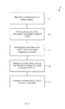
- FIG. 1 schematically depicts a metal injection molding method according to the present disclosure.
- FIG. 2 schematically depicts an example of forming a feedstock according to the method of FIG. 1 .
- FIG. 3 schematically depicts an example of molding the feedstock into a molded article according to the method of FIG. 1 .
- FIG. 4A schematically depicts an example of the metal injection molding method of FIG. 1 with an alcohol immersion step for substantially removing the aromatic binder.
- FIG. 4B schematically depicts another example of the metal injection molding method of FIG. 1 with an atmospheric pressure heating step for substantially removing the aromatic binder.
- FIG. 4C schematically depicts another example of the metal injection molding method of FIG. 1 with a heated vacuum step for substantially removing the aromatic binder.
- FIG. 5 schematically depicts an example of sintering the molded article into the metal article according to the method of FIG. 1 .
- FIG. 6 schematically depicts an example of a metal injection molding and oxygen reduction method according to the present disclosure.
- FIG. 7 schematically depicts an example of a metal injection molding and densification method according to the present disclosure.
- FIG. 8 schematically depicts a feedstock according to the present disclosure.
- a metal injection molding method 10 may include forming a feedstock 20 , molding the feedstock into a molded article 30 , substantially removing an aromatic binder 40 , and sintering the molded article into a metal article 50 .
- Method 10 can be carried out from a lab scale to a mass production scale. Any suitable production equipment may be used, including vessels, containers, impellers, mixers, granulators, injection molding machines, vacuum furnaces, vacuum ovens, and dryers.
- Forming a feedstock 20 may be conducted under a cover of inert gas, such as argon. However, an inert gas cover is not necessary, and the feedstock may be formed in an atmosphere of air.
- Forming a feedstock 20 produces a mixture that imparts desired properties into the final metal article and that allows the molded article to retain its shape during processing.
- forming the feedstock 20 may include adding an aromatic binder 80 to a vessel 21 .
- the vessel is sealable to prevent evaporation of components, includes a variable speed mixing blade with a sealed shaft, and can be heated to specified temperatures.
- a suitable amount of aromatic binder 80 includes 20-40% aromatic binder (all percentages are by volume of the feedstock, unless indicated otherwise). More preferably, 28-32% aromatic binder may be added to the vessel.
- Aromatic binder 80 can be any of a number of aromatic compounds. Aromatic binders 80 having relatively low melting and/or sublimation temperatures may be particularly suitable. For example, naphthalene melts at 176° F. and sublimates at room temperature. Aromatic binder 80 ideally helps retain the shape of the molded article and is removable via relatively low temperature means.
- forming a feedstock 20 may include adding a lubricant 82 to the vessel 22 .
- Lubricant 82 typically aids in the removal of molded articles from the mold as well as improving the flow characteristics of feedstock 90 .
- Lubricant 82 may include organic, fatty acids, such as stearic acid. Additionally or alternatively, lubricant 82 may include solid waxes, such as microcrystalline waxes.
- a suitable lubricant addition range includes 0-10% lubricant, preferably 0-6% lubricant, and more preferably 3-6% lubricant.
- the vessel components are typically heated and mixed 23 , such as by stirring, to form a uniform liquid as provided in FIG. 2 .
- the vessel may be heated to a temperature above the melting point of the aromatic binder. When naphthalene is used as the aromatic binder, the vessel is heated to approximately 200° F.
- adding a thermoplastic 84 to the vessel 24 may occur while the vessel is typically being heated and mixed.
- Thermoplastic 84 may be a solid at room temperature, such as in the form of solid beads.
- the vessel may be heated and mixed until thermoplastic 84 is dissolved 25 . In examples where thermoplastic 84 is polystyrene, dissolution can occur in approximately 10 minutes.
- thermoplastics may be used in method 10 and feedstock 90 to strengthen the molded article.
- Polystyrene is one example of a suitable thermoplastic.
- Thermoplastic 84 may additionally or alternatively include ethylene vinyl acetate, polyethylene, and butadiene. Suitable thermoplastic addition ranges include 5-15% thermoplastic, and preferably 8-12% thermoplastic.
- forming the feedstock 20 includes adding a metal powder 86 to the vessel 26 .
- Metal powder 86 may constitute the remaining volume of the mixture.
- metal powder 86 may represent 35-74%, and preferably 44-69% of feedstock 90 .
- adding metal powder 86 to the vessel 26 occurs while mixing the contents of the vessel and maintaining the mixture temperature at approximately 200° F.
- Metal power 86 defines many of the properties of the final metal article.
- a variety of metal powders may be used, such as powders of copper, stainless steel, titanium, tantalum, and cobalt, as well as alloys and combinations thereof. Titanium has been found particularly suitable for certain applications. Pure titanium, titanium alloys, such as titanium and a blend of elements, titanium hydride, and titanium matrix composites may be used.
- Metal powder 86 may have a spherical shape, an angular shape, and combinations thereof. The size of metal powder 86 typically ranges between 30 to 75 microns.
- forming a feedstock 20 typically includes continuing to heat the vessel contents while mixing until the viscosity of the mixture remains constant 27 . In some examples, the viscosity remains constant after 20 to 30 minutes of mixing and heating. Once the viscosity becomes constant, a uniform liquid is formed, which represents feedstock 90 .
- feedstock 20 may optionally include the step of cooling feedstock 90 until it solidifies 28 .
- Feedstock 90 may be granulated into a powder by continuing to stir feedstock 90 as it is cooled.
- feedstock 90 may be discharged onto a metal sheet and allowed to cool. After solidifying on the metal sheet, feedstock 90 is typically ground into a powder.
- feedstock 90 is stored in a sealed container after granulation.
- Method 10 includes the step of molding feedstock 90 into a molded article 30 to give feedstock 90 , and eventually the metal article, a desired shape.
- molding the feedstock 30 may include loading feedstock 90 into an injection molding machine 31 .
- Any type of injection molding machine compatible with the composition and properties of feedstock 90 may be used.
- Many standard plastic injection molding machines are suitable. Injection molding machines including a barrel and a die cavity (mold) are well known in the art.
- Molding feedstock 90 into a molded article 30 may include heating the barrel of the injection molding machine to a barrel temperature 32 to heat feedstock 90 within the barrel. Barrel temperatures slightly higher than the melting point of the aromatic binder are preferred. Higher barrel temperatures can undesirably cause the composition of feedstock 90 to change. Among other undesirable consequences, a changed feedstock composition precludes the option of remolding imperfect molded articles. Typically, barrel temperatures of not more than 200° F. are used to inhibit gas bubble formation, which can cause structural defects within the molded article.
- molding the feedstock 30 may include maintaining the temperature of a mold at a mold temperature 33 to cause feedstock to solidify into the molded article.
- the mold may be maintained at a mold temperature of not more than 120° F., preferably at a temperature of not more than 90° F., and more preferably at a temperature of between 50 to 90° F.
- a mold temperature of 70° F. is targeted.
- Feedstock 90 may be pressurized to an injection pressure 34 to inject feedstock 90 into the mold 35 .
- Pressures of 100 to 1,000 psi are suitable for the injection pressure. In some examples, injection pressures of approximately 400-500 psi are used. Injection pressures higher than 1000 psi can damage the mold and result in improperly molded articles. It is known in the art to use injection pressures exceeding 3,000 psi, and even as high as 20,000 psi, presumably to inhibit gas bubble formation within the molded article from high barrel temperatures, such as for barrel temperatures exceeding 200° F. However, high injection pressures to inhibit gas bubble formation are not necessary when a barrel temperature of not more than 200° F. is selected for feedstocks according to the present disclosure.
- method 10 typically includes the step of substantially removing the aromatic binder 40 . As shown in FIGS. 4-6 , a variety of methods 40 A, 40 B, and 40 C for substantially removing the aromatic binder are contemplated.
- substantially removing the aromatic binder 40 A may include providing an alcohol bath 41 A, such as an ethanol bath.
- the alcohol bath is kept at ambient temperature.
- the alcohol bath is continuously distilled and replaced to reduce costs and to facilitate keeping the alcohol below the saturation point of the aromatic binder.
- the molded article is then immersed in the alcohol bath 42 A to dissolve the aromatic binder. Often times, other components, such as the lubricant, will dissolve into the alcohol bath as well.
- the molded article is kept in the alcohol bath until a desired amount of aromatic binder and other components have been removed, which may take between 4 and 24 hours depending on the size of the molded article.
- the molded article is removed from the alcohol bath and dried 43 A. Drying 43 A may be conducted by heating the molded article to a temperature below the melting point of the thermoplastic remaining in the molded article, such as a temperature between ambient and 150° F. Drying may be conducted in an oven under vacuum or with moving air. The molded article may be cooled or allowed to cool to ambient temperature after drying 43 A.
- Method 40 B includes placing the molded article onto a suitable support 41 B.
- a support is suitable if it inhibits pick-up of oxygen, carbon, or other impurities in the molded article during the aromatic binder removal process.
- Suitable supports include zirconia or yittria, or supports coated with zirconia or yittria.
- the molded article is heated, in an oven or the like, to a first temperature 42 B. In some examples, the first temperature is between 100 and 140° F.
- the amount of aromatic binder removed is monitored 43 B to determine when a target amount, such as 85%, of the aromatic binder has been removed. Once the target amount of aromatic binder has been removed, heating of the molded article to the first temperature is stopped 44 B. In some examples, it can take between 24 and 240 hours to remove the target amount of aromatic binder, depending on the size of the molded article.
- method 40 C includes placing the molded article onto a suitable support 41 C, such as supports made of zirconia or yittria, or supports coated with zirconia or yittria.
- the molded article is heated under vacuum to a first temperature 42 C. In some examples, the first temperature is between 80 and 120° F.
- the amount of aromatic binder removed is monitored 43 C to determine when a target amount, such as 85%, of the aromatic binder has been removed.
- the molded article is heated to a second temperature 44 C, such as 300° F., to substantially remove the remaining aromatic binder.
- Other components, such as the lubricant may also be removed. In some examples, it can take between 24 and 72 hours to substantially remove the aromatic binder, depending on the size of the molded article.
- FIG. 5 An example of a method for sintering the molded article to into a metal article 50 is provided in FIG. 5 .
- Sintering is performed to consolidate the molded article into a dense metal article.
- the molded article is placed on a suitable support 51 , such as supports made of zirconia or yittria, or supports coated with zirconia or yittria.
- the supported molded article is then typically placed into a vacuum furnace.
- the pressure of the vacuum furnace may be reduced 52 , such as to below 50 microns.
- the temperature of the vacuum furnace is typically ramped up to a peak temperature 53 , such as a peak temperature of 2,450° F.
- peak temperatures may be selected.
- different temperature ramping rates may be selected to effectuate removal of the thermoplastic from the molded article. In general, a slower ramp rate allows more time for the thermoplastic to be removed. Ramp rates of 1 to 20 hours have been effectively used, depending on the size of the article and the amount of thermoplastic to be removed.
- the molded article is typically held at the peak temperature for a hold time 54 , such as a hold time of 1 hour, and then cooled to a cool down temperature 55 , such as 200° F.
- the hold time is selected to allow for sufficient densification via sintering. In some examples, metal articles having densities of 97% are achieved through sintering. Introducing argon or helium gas in conjunction with a fan and heat exchanger can bring about rapid cooling.
- the article removed from the vacuum oven and resulting from sintering method 50 is a metal article in a final form.
- Metal articles formed via the metal injection molding methods 10 described herein, typically meet aerospace and medical grade specifications for all alloying constituents.
- One example of a specification that metal articles produced via method 10 routinely meet is ASTM F 1474 for Ti 6Al 4V alloy.
- Another example is for Ti 6Al 4V/10% TiC matrix composite, as well as standard grade 2, 3, 4, and 5 titanium.
- Oxygen concentrations in the final metal article are typically less than 2000 ppm, carbon concentrations are routinely less than 800 ppm, and nitrogen concentrations are most often below 500 ppm. Additional and/or alternative methods are shown in FIGS. 6 and 7 for producing metal articles with reduced oxygen levels and increased densities.
- metal injection molding and oxygen reduction method 100 is shown in FIG. 6 .
- Method 100 is similar in many respects to method 10 , with a further included oxygen reduction method 160 . Accordingly, similar method steps are given similar 100 level numbers, e.g. 20 v. 120 .
- metal injection molding and oxygen reduction method 100 may include forming a feedstock 120 ; molding the feedstock into a molded article 130 ; substantially removing the aromatic binder 140 ; sintering the molded article into a metal article 150 ; and reducing the oxygen level of the metal article 160 .
- steps 20 , 30 , 40 , and 50 above will be relied upon for the description of steps 120 , 130 , 140 , and 150 .
- Reducing the oxygen level in the metal article 160 is described more fully below. Reducing the oxygen level in the metal article 160 is most often employed when the metal article is a reactive metal.
- reducing the oxygen level 160 typically starts by enclosing the metal article in a container with a deoxidizing agent 161 .
- Suitable deoxidizing agents include certain alkali and alkaline earth metals. Sodium, magnesium, and calcium metals have proved effective as deoxidizing agents. Preferably, calcium metal is used as the deoxidizing agent. In some examples, deoxidizing agent in an amount equal to 1-10% of the metal article weight is used.
- the air inside the container may be replaced with an inert gas to a selected pressure 162 .
- Purified argon gas is suitable for the inert gas and positive pressures of 5 psi have proved effective.
- the container may be heated 163 and held at an elevated temperature for a period of time.
- the elevated temperature is typically selected to be higher than the melting point of the deoxidizing agent, which in the case of calcium metal is 1542° F.
- the container may be heated to a temperature of between 1600 and 1800° F. while under 5 psi of pressure. Higher temperatures could also be used. However, at higher temperatures, consideration must be given to the chance that titanium might form a eutectic with the container and result in a melt through, such as when the container is made from stainless steel.
- the container is typically held at approximately 1800° F. and 5 psi for between 2 and 24 hours, then cooled to ambient temperature 164 .
- the metal article may then be washed in an acid solution 165 to remove any residual calcium and calcium oxide that may be present on the surface of the metal article.
- Metal articles produced via metal injection molding and oxygen reduction methods 100 routinely meet extra low interstitial ASTM F 136 standards for eli grade Ti 6Al 4V. Oxygen reduction also facilitates enhanced ductility of the metal article, which can be an important property in the medical and aerospace industries.
- metal injection molding and densification method 200 is shown in FIG. 7 .
- Method 200 is similar in many respects to method 10 , with a further included densification method 270 . Accordingly, similar method steps are given similar 200 level numbers, e.g. 20 v. 220 .
- metal injection molding and densification method 200 may include forming a feedstock 220 ; molding the feedstock into a molded article 230 ; substantially removing the aromatic binder 240 ; sintering the molded article into a metal article 250 ; and increasing the density of the metal article 270 .
- steps 20 , 30 , 40 , and 50 above will be relied upon for the description of steps 220 , 230 , 240 , and 250 .
- Increasing the density of the metal article 270 is described more fully below.
- densification method 270 typically includes surrounding the metal article with an inert gas 271 , such as purified argon. Surrounding the metal article with an inert gas 271 can be thought of as creating a metal article-inert gas system. Densification method 270 may proceed by heating the metal article-inert gas system to a densification temperature 272 .
- the densification temperature may range from between 1,600 and 2,225° F. In examples where the metal power includes cobalt chrome, a densification temperature range of between 1,600 and 2,225° F. is suitable. In examples where the metal powder includes titanium, a densification temperature range of between 1,600 and 1,750° F. is preferred.
- the densification method 270 shown in FIG. 7 includes pressuring the metal article-inert gas system to a densification pressure 273 .
- a range of densification pressures are suitable, and at least 15,000 psi has been found to be effective.
- a densification pressure range of between 15,000 and 45,000 psi is used. More preferably, a densification pressure range of between 15,000 and 25,000 psi is employed.
- the metal powder includes titanium
- a densification pressure range of between 15,000 and 20,000 psi is typically selected. After heating 272 and pressurizing 273 the metal article, densities approaching 100% are routinely obtained.
- Feedstock Weight (g) Component
- Example 1 Example 2
- Example 3 Example 4
- Example 6 Naphthalene 183.69 167.09 152.4 158.9 15 Polystyrene 52.48 45.4 43.69 45.4 3
- Stearic acid 26.54 22.7 21.8 22.7 2
- Metal powder 2000 - stainless steel 2000 - 1058.85 - Ti 6Al 4V 1153 - Ti 6Al 4V 80 - TiH 2 (400 mesh 17-4 ph) Co/Cr/Mo (44 micron) (44 micron, spherical) (200 mesh) (16 micron) 86.01 - TiC (5 micron)
- Example 1 demonstrates one embodiment of a metal injection molding method for forming a stainless steel metal article.
- the amounts of each feedstock component used are provided in Table 1 above.
- the naphthalene was added to a mixer and heated to 200° F.
- the polystyrene was added and stirred until dissolved.
- the stearic acid was added and melted.
- the stainless steel powder was added and blended until a consistent liquid was formed. After approximately 20 minutes, the liquid mixture was poured into an aluminum foil lined pan and allowed to cool to approximately room temperature. The hardened slab was broken up and placed into a grinder, which pulverized the mixture into a coarse powder. The resulting coarse powder was used as a feedstock to make the stainless steel metal article.
- the feedstock was added to the hopper of an Arburg plastic injection machine and injection molded into a steel cavity test bar die.
- the injection pressure was set at 500 psi and the nozzle temperature was set at 190° F.
- the resulting injected test bars weighed 11.8 g each.
- the test bars were placed on Zirconia coated graphite plates and placed in a vacuum oven.
- the oven was evacuated to below 100 microns pressure and heated to 90° F. and held for 20 hours.
- the temperature was raised to 140° F. over a period of 12 hours and held for another 20 hours.
- the oven was then heated to 200° F. over a period of 12 hours and held for another 20 hours, at which time the heat was turned off and the parts were cooled to room temperature under vacuum.
- the debinded parts weighed approximately 1 g less than before the vacuum debinding cycle.
- the debinded test bars were placed into a high temperature vacuum furnace, heated over a controlled cycle to 2,250° F., and held for 2 hours at that temperature. After cooling, the bars were mechanically tested. The testing results are shown in Table 2 below.
- Example 1 Example 2
- Example 3 Example 4
- Example 2 demonstrates one embodiment of a metal injection molding method for forming a Co/Cr/Mo metal article.
- the amounts of each feedstock component used are provided in Table 1 above.
- the naphthalene was melted at 200° F. in a 1 gal. mixer.
- the stearic acid was added to the mixer and melted into the 200° F. naphthalene.
- the polystyrene was subsequently added to the mixer.
- the mixture was stirred until the polystyrene dissolved.
- the Co/Cr/Mo powder was slowly added to the mixer while continuing to stir the mixture.
- the mixture was stirred for approximately 30 minutes, after which it was discharged onto a pan lined and covered in aluminum foil.
- the mixture was then cooled on the pan to room temperature.
- the slab was broken into chunks, and the chunks were fed into a grinder and ground into a coarse powder feedstock.
- the feedstock was added to the hopper of an Arburg plastic injection machine.
- the temperature of the barrel nozzle was set at 190° F., and the injection pressure was set at 500 psi.
- the feedstock was injected into a test bar die and several test bar shapes were made weighing 12.56 g each.
- the binder was removed from the test bars by placing them into a vacuum oven.
- the pressure of the vacuum oven was reduced to below 100 microns and the vacuum oven was held at 90° F. for 20 hours. Subsequently, the temperature was raised to 140° F. over a period of 12 hours and held for another 20 hours. The oven was then heated to 200° F. over a period of 12 hours and held for another 20 hours, at which time the heat was turned off and the parts were cooled to room temperature under vacuum.
- the test bars had a weight loss of approximately 0.9 g each.
- test bars To sinter the test bars, they were loaded into a vacuum sintering furnace and heated to 2,250° F. at a partial pressure of 200 microns of Argon gas for approximately 1 hour. The furnace was subsequently gas fan cooled to below 200° F.
- test bars After being sintered, the test bars were removed and sent out for HIP (hot isostatic pressing) at 25,000 psi and 2,165° F. for 4 hours. Following the HIP process, the test bars were solution annealed at 2,175° F. in a vacuum furnace for 4 hours. The test bars were then gas fan cooled and sent out for testing. Chemistry tests showed that the bars conformed to ASTM F-75 chemistry. Mechanical testing results are shown in Table 2 above.
- HIP hot isostatic pressing
- Example 3 demonstrates one embodiment of a metal injection molding method for forming a titanium matrix composite metal article.
- the amounts of each feedstock component used are provided in Table 1 above.
- the naphthalene and stearic acid were melted together in a heated container at 200° F.
- the polystyrene was added to the mixture and stirred until dissolved.
- the TiC powder was dry blended with the Ti 6Al 4V powder and slowly added to the liquid naphthalene mixture.
- the resulting liquid feedstock mixture was poured onto an aluminum foil lined pan, covered, and cooled to room temperature. The cooled slab was broken into smaller pieces, processed through a lab granulator, and ground into a coarse powder, which was stored in a sealed container.
- the granulated feedstock was subsequently loaded into an Arburg plastic injection machine.
- the temperature of the barrel nozzle was set at 190° F., and the injection pressure was set at 500 psi.
- Several injections were performed to produce test bars weighing 7.6 g each.
- test bars To remove binder from the test bars, they were immersed in a circulating alcohol bath at room temperature for 12 hours. The test bars were then removed from the alcohol bath, placed in a drying oven at 150° F. for 1 hour, and weighed. The average weight of the bars was 6.9 g.
- the dried bars were placed on zirconia board and loaded into a vacuum sintering furnace.
- the furnace was evacuated to below 5 microns of pressure and slowly heated to a peak temperature of 2,450° F. Upon reaching the peak temperature, the furnace was held at that temperature for one hour. The bars were then furnace cooled to below 200° F. and removed.
- the sintered bars were subjected to HIP processing.
- the HIP processing involved heating the bars to 1,650° F. in argon gas and pressurizing them to 15,000 psi. The bars were then allowed to cool and sent out for mechanical and chemical testing.
- the mechanical properties are provided in Table 2 above.
- the chemical composition of the test bars is provided in Table 3 below.
- Example 4 demonstrates one embodiment of a metal injection molding method for forming a titanium alloy metal article.
- the amounts of each feedstock component used are provided in Table 1 above.
- feedstock ingredients were placed in a covered and heated sigma blade mixer with an auger extruder discharge.
- the temperature of the mixer was set at 200° F.
- the blade speed was set at approximately 40 rpm, and the ingredients were mixed until the batch liquefied. Upon liquefying, the ingredients were mixed another half hour to ensure consistency.
- the heat was then turned off while continuing to mix the feedstock as it cooled.
- the feedstock granulated into a coarse powder as it solidified during cooling.
- the granulated feedstock was then discharged into a plastic container.
- the granulated feedstock was loaded into an Arburg plastic injection machine with a nozzle temperature setting of 190° F. and an injection pressure setting of 500 psi.
- the feedstock was injected into a die cavity to form test bars weighing 8.56 g each.
- the binder was removed from the test bars in a vacuum oven heated to between 100° F. and 300° F. over a period of 72 hours.
- test bars To sinter the test bars, they were loaded into a vacuum sinter furnace and further processed on the following heat cycle under less than 5 microns vacuum: 1) heating the furnace from 75° F. to 625° F. over 30 minutes; 2) maintaining the furnace at 625° F. for 30 minutes; 3) ramping the heat to 750° F. over 30 minutes; 4) maintaining the furnace at 750° F. for 30 minutes; 5) ramping the furnace temperature to 900° F. over 1 hour; 6) maintaining the furnace at 900° F. for 1 hour; 7) ramping the furnace temperature to 2450° F. over 5 hours; 8) maintaining the furnace temperature at 2450° F. for 1 hour; and 9) turning off the furnace heat and allowing it to cool.
- test bars were subjected to HIP processing.
- HIP processing involved heating the bars to 1650° F. and pressurizing them to 15,000 psi for 2 hours.
- Chemical testing data and mechanical testing data of the resulting test bars are shown above in Tables 2 and 3, respectively.
- Example 5 demonstrates one embodiment of an oxygen reduction method according to the present disclosure for use in conjunction with metal injection molding methods.
- a stainless steel retort with a sealable lid was used to remove oxygen from metal injection molding parts weighing approximately 2.5 g each.
- Four cervical disc shaped parts made from the same Ti 6Al 4V metal injection molding feedstock were coded by scribing them with the letters A,B,C, and R.
- the code C part was not processed, but instead was used as a control to compare its oxygen content to the other parts.
- the other three parts were suspended in a retort with a 1:1 ratio of calcium metal shot.
- the retort was evacuated and backfilled three times before applying heat. Subsequently, the retort was pressurized to 5 psi and heated to 1770° F. while maintaining an argon gas pressure of 2 to 5 psi.
- the temperature of the retort was held at 1770° F. for 5 hours, and then the heat was turned off and the retort allowed to cool while maintaining a positive gas pressure of 2 to 5 psi. After cooling, the parts were removed and soaked in a 5% HCI solution for 4 hours to remove deposits from the surface of the parts. The parts were then rinsed in deionized water, air dried, and tested for bulk oxygen analysis. The bulk oxygen analysis results are shown in Table 4 below.
- Example 6 demonstrates one embodiment of a metal injection molding method for forming a titanium hydride metal article.
- the amounts of each feedstock component used are provided in Table 1 above.
Abstract
Description
| TABLE 1 |
| Feedstock Compositions |
| Feedstock | Weight (g) |
| Component | Example 1 | Example 2 | Example 3 | Example 4 | Example 6 |
| Naphthalene | 183.69 | 167.09 | 152.4 | 158.9 | 15 |
| Polystyrene | 52.48 | 45.4 | 43.69 | 45.4 | 3 |
| Stearic acid | 26.54 | 22.7 | 21.8 | 22.7 | 2 |
| Metal powder | 2000 - stainless steel | 2000 - | 1058.85 - Ti 6Al 4V | 1153 - Ti 6Al 4V | 80 - TiH2 |
| (400 mesh 17-4 ph) | Co/Cr/Mo | (44 micron) | (44 micron, spherical) | (200 mesh) | |
| (16 micron) | 86.01 - TiC (5 micron) | ||||
| TABLE 2 |
| Mechanical Testing Results |
| Test Parameter | Example 1 | Example 2 | Example 3 | Example 4 |
| Tensile | 170 | 135 | 148.6 | 137.1 to 140.3 |
| Strength | ||||
| (ksi) | ||||
| Yield Strength | 158 | 70 | 138.5 | 123.7 to 126.2 |
| (ksi) | ||||
| Elongation (%) | Not Tested | 22 | 4 | 9 to 11.5 |
| Area Reduction | Not Tested | Not Tested | 7.6 | 21.5 to 22 |
| (%) | ||||
| TABLE 3 |
| Chemical Composition Results |
| Composition | ||
| Chemical | (%) |
| Element | Example 3 | Example 4 | Example 6 | ||
| N | .03 | Not tested | Not tested | ||
| C | 1.44 | 0.0497 | 0.0316 | ||
| H | .001 | Not tested | Not tested | ||
| Fe | .07 | Not tested | Not tested | ||
| O | .18 | 0.197 | 0.38 | ||
| Al | 5.6 | Not tested | Not tested | ||
| V | 3.6 | Not tested | Not tested | ||
| Ti | Balance | Not tested | Not tested | ||
| TABLE 4 |
| Bulk Oxygen Concentration |
| Bulk Oxygen Concentration | |||
| Sample Part | (%) | ||
| Code C | 0.221 | ||
| (control) | |||
| Code A | 0.121 | ||
| Code B | 0.123 | ||
| Code R | 0.101 | ||
| Parts heated to | 0.077-0.079 | ||
| 1770° F. for 10 hours | |||
Claims (22)
Priority Applications (1)
| Application Number | Priority Date | Filing Date | Title |
|---|---|---|---|
| US11/941,018 US7883662B2 (en) | 2007-11-15 | 2007-11-15 | Metal injection molding methods and feedstocks |
Applications Claiming Priority (1)
| Application Number | Priority Date | Filing Date | Title |
|---|---|---|---|
| US11/941,018 US7883662B2 (en) | 2007-11-15 | 2007-11-15 | Metal injection molding methods and feedstocks |
Publications (2)
| Publication Number | Publication Date |
|---|---|
| US20090129961A1 US20090129961A1 (en) | 2009-05-21 |
| US7883662B2 true US7883662B2 (en) | 2011-02-08 |
Family
ID=40642165
Family Applications (1)
| Application Number | Title | Priority Date | Filing Date |
|---|---|---|---|
| US11/941,018 Active 2029-07-25 US7883662B2 (en) | 2007-11-15 | 2007-11-15 | Metal injection molding methods and feedstocks |
Country Status (1)
| Country | Link |
|---|---|
| US (1) | US7883662B2 (en) |
Cited By (2)
| Publication number | Priority date | Publication date | Assignee | Title |
|---|---|---|---|---|
| US20130216420A1 (en) * | 2010-10-08 | 2013-08-22 | Yadong Li | Manufacturing method of multilayer shell-core composite structural component |
| US20140127068A1 (en) * | 2011-06-13 | 2014-05-08 | Charles Malcolm Ward-Close | Production of metal or alloy objects |
Families Citing this family (16)
| Publication number | Priority date | Publication date | Assignee | Title |
|---|---|---|---|---|
| US20090208360A1 (en) | 2008-02-20 | 2009-08-20 | The Boeing Company | Binderless metal injection molding apparatus and method |
| US20170022831A9 (en) * | 2011-08-31 | 2017-01-26 | Pratt & Whitney Canada Corp. | Manufacturing of turbine shroud segment with internal cooling passages |
| TWI572842B (en) * | 2012-03-16 | 2017-03-01 | 鴻準精密工業股份有限公司 | Manufacturing method for heat pipe and heat pipe making through the method |
| KR20140048428A (en) * | 2012-10-15 | 2014-04-24 | 현대자동차주식회사 | Method for manufacturing of control finger using with metal powder injection molding |
| EP2767355B1 (en) * | 2013-02-18 | 2021-03-10 | Grundfos Holding A/S | Segmented core and method for moulding an impeller |
| CN103920881A (en) * | 2014-04-11 | 2014-07-16 | 宝得粉末注射成形(常熟)有限公司 | Easy-removal binder for powder injection molding |
| US9782828B2 (en) * | 2014-10-20 | 2017-10-10 | The Boeing Company | Methods for forming near net-shape metal parts from binderless metal powder |
| CN104959615B (en) * | 2015-07-27 | 2017-07-28 | 长沙瑞泰医学科技有限公司 | The preparation method of orthopaedics implant shaped piece |
| KR101788139B1 (en) | 2015-11-27 | 2017-11-16 | 한국생산기술연구원 | Binder composition for powder metallurgy |
| US11077497B2 (en) | 2017-06-07 | 2021-08-03 | Global Titanium Inc. | Deoxidation of metal powders |
| US10502093B2 (en) * | 2017-12-13 | 2019-12-10 | Pratt & Whitney Canada Corp. | Turbine shroud cooling |
| US11274569B2 (en) | 2017-12-13 | 2022-03-15 | Pratt & Whitney Canada Corp. | Turbine shroud cooling |
| US10570773B2 (en) | 2017-12-13 | 2020-02-25 | Pratt & Whitney Canada Corp. | Turbine shroud cooling |
| US10533454B2 (en) | 2017-12-13 | 2020-01-14 | Pratt & Whitney Canada Corp. | Turbine shroud cooling |
| US11365645B2 (en) | 2020-10-07 | 2022-06-21 | Pratt & Whitney Canada Corp. | Turbine shroud cooling |
| WO2022260356A1 (en) * | 2021-06-10 | 2022-12-15 | 한국피아이엠(주) | Metal powder injection molded product for manufacturing metal frame basic product, system comprising same metal powder injection molded product, and method for manufacturing metal frame basic product by using same |
Citations (59)
| Publication number | Priority date | Publication date | Assignee | Title |
|---|---|---|---|---|
| US2478420A (en) | 1947-03-13 | 1949-08-09 | Crucible Steel Co America | Steel for plastic mold dies and articles made therefrom |
| US3155502A (en) | 1960-08-12 | 1964-11-03 | Union Carbide Corp | Powder metallurgy |
| US3302073A (en) | 1963-10-21 | 1967-01-31 | Gen Electric | Electrical capacitors and electrode material therefor |
| US3325277A (en) | 1965-02-01 | 1967-06-13 | Smith Corp A O | Method of making metal powder |
| US3330892A (en) | 1964-07-24 | 1967-07-11 | Corning Glass Works | Molding comminuted nonplastic inorganic material |
| US3725142A (en) | 1971-08-23 | 1973-04-03 | Smith A Inland Inc | Atomized steel powder having improved hardenability |
| US3769044A (en) | 1970-12-02 | 1973-10-30 | Precision Metalsmiths Inc | Compositions and methods for making molded refractory articles |
| US3802939A (en) | 1971-03-22 | 1974-04-09 | Kobe Steel Ltd | Surface-hardened titanium or zirconium and their alloys and method of processing same |
| US3841848A (en) | 1970-01-30 | 1974-10-15 | Suwa Seikosha Kk | HARD WATCH CASE COMPRISING TiN, T, AND AT LEAST ONE OF Mn, Al AND V |
| US3864809A (en) | 1973-03-29 | 1975-02-11 | Int Nickel Co | Process of producing by powder metallurgy techniques a ferritic hot forging of low flow stress |
| US4049429A (en) | 1973-03-29 | 1977-09-20 | The International Nickel Company, Inc. | Ferritic alloys of low flow stress for P/M forgings |
| US4284121A (en) | 1980-02-28 | 1981-08-18 | Precision Metalsmiths, Inc. | Process and materials for making refractory cores |
| US4448746A (en) | 1982-11-05 | 1984-05-15 | Sumitomo Metal Industries, Ltd. | Process for producing alloy steel powder |
| US4457851A (en) | 1981-12-29 | 1984-07-03 | Hitachi Metals, Ltd. | Ferrite magnet and method of producing same |
| US4478790A (en) | 1981-05-22 | 1984-10-23 | Mtu Motoren-Und Turbinen-Union Munchen Gmbh | Method and apparatus for manufacturing molded articles of alloyed material |
| JPS60216512A (en) | 1984-04-12 | 1985-10-30 | Seiko Epson Corp | Magnet for magnetic roll |
| US4606767A (en) | 1984-10-30 | 1986-08-19 | Kyocera Corporation | Decorative silver-colored sintered alloy |
| US4721599A (en) | 1985-04-26 | 1988-01-26 | Hitachi Metals, Ltd. | Method for producing metal or alloy articles |
| US4765950A (en) | 1987-10-07 | 1988-08-23 | Risi Industries, Inc. | Process for fabricating parts from particulate material |
| US4894088A (en) | 1986-12-16 | 1990-01-16 | Kabushiki Kaisha Kobe Seiko Sho | Pellet for fabricating metal matrix composite and method of preparing the pellet |
| US4964907A (en) | 1988-08-20 | 1990-10-23 | Kawasaki Steel Corp. | Sintered bodies and production process thereof |
| US5022935A (en) * | 1988-09-23 | 1991-06-11 | Rmi Titanium Company | Deoxidation of a refractory metal |
| JPH04116104A (en) | 1990-09-07 | 1992-04-16 | Hitachi Metal Precision Ltd | Production of molded body for sintering and sintered parts |
| US5159007A (en) | 1987-06-25 | 1992-10-27 | Idemitsu Petrochemical Co., Ltd. | Metal binder and molding compositions |
| US5194203A (en) * | 1991-02-28 | 1993-03-16 | Mitsui Mining & Smelting Co., Ltd. | Methods of removing binder from powder moldings |
| US5211775A (en) | 1991-12-03 | 1993-05-18 | Rmi Titanium Company | Removal of oxide layers from titanium castings using an alkaline earth deoxidizing agent |
| JPH062011A (en) | 1992-06-24 | 1994-01-11 | Agency Of Ind Science & Technol | Production of powder compact |
| US5308576A (en) | 1991-10-18 | 1994-05-03 | United States Surgical Corporation | Injection molded anvils |
| US5338508A (en) | 1988-07-13 | 1994-08-16 | Kawasaki Steel Corporation | Alloy steel powders for injection molding use, their compounds and a method for making sintered parts from the same |
| US5403374A (en) | 1991-05-31 | 1995-04-04 | Sumitomo Electric Industries, Ltd. | Watch exterior parts and manufacturing method thereof |
| JPH0790318A (en) | 1993-06-25 | 1995-04-04 | Kawasaki Steel Corp | Production of titanium sintered body by metal powder injection molding method |
| US5403411A (en) | 1992-03-23 | 1995-04-04 | The United States Of America As Represented By The Secretary Of The Air Force | Method for increasing the fracture resistance of titanium composites |
| US5441695A (en) | 1993-07-23 | 1995-08-15 | Asulab S.A. | Process for the manufacture by sintering of a titanium part and a decorative article made using a process of this type |
| US5464670A (en) | 1990-04-13 | 1995-11-07 | Seiko Epson Corporation | Resin bound magnet and its production process |
| US5545248A (en) | 1992-06-08 | 1996-08-13 | Nippon Tungsten Co., Ltd. | Titanium-base hard sintered alloy |
| JPH0913153A (en) | 1995-04-25 | 1997-01-14 | Daido Steel Co Ltd | Treatment of titanium sintered body |
| JPH09148166A (en) | 1996-08-27 | 1997-06-06 | Seiko Epson Corp | Manufacture of resin-bonded magnet |
| US5665289A (en) * | 1990-05-07 | 1997-09-09 | Chang I. Chung | Solid polymer solution binders for shaping of finely-divided inert particles |
| US5733580A (en) | 1989-03-18 | 1998-03-31 | Seiko Epson Corporation | Dies for extrusion moulding |
| US5738817A (en) | 1996-02-08 | 1998-04-14 | Rutgers, The State University | Solid freeform fabrication methods |
| US5782954A (en) | 1995-06-07 | 1998-07-21 | Hoeganaes Corporation | Iron-based metallurgical compositions containing flow agents and methods for using same |
| US5848350A (en) | 1997-10-31 | 1998-12-08 | Flomet, Inc. | Nickel-free stainless steel alloy processible through metal injection molding techniques to produce articles intended for use in contact with the human body |
| US5854379A (en) | 1994-03-14 | 1998-12-29 | Kabushiki Kaisha Komatsu Seisakusho | Thermal decomposition degreasing method and molded products thereof |
| US6027686A (en) | 1996-06-25 | 2000-02-22 | Injex Corporation | Method of manufacturing sintered compact |
| US6075083A (en) | 1997-12-15 | 2000-06-13 | Ceramet Technologies Pte. Ltd. | Mouldable composition and process |
| US6306196B1 (en) | 1999-08-04 | 2001-10-23 | Hitachi Metals, Ltd. | Sintered Ti-system material product derived from injection molding of powder material and producing method thereof |
| US6376585B1 (en) | 2000-06-26 | 2002-04-23 | Apex Advanced Technologies, Llc | Binder system and method for particulate material with debind rate control additive |
| US6555051B1 (en) | 1998-10-13 | 2003-04-29 | Injex Corporation | Method for producing sintered body |
| US6689311B2 (en) | 2000-11-13 | 2004-02-10 | Matsushita Electric Industrial Co., Ltd. | Method and apparatus for manufacturing sinter, method for measuring concentration of plasticizer, evaluation method, and evaluation apparatus |
| US6725901B1 (en) | 2002-12-27 | 2004-04-27 | Advanced Cardiovascular Systems, Inc. | Methods of manufacture of fully consolidated or porous medical devices |
| US6759004B1 (en) | 1999-07-20 | 2004-07-06 | Southco, Inc. | Process for forming microporous metal parts |
| US6770114B2 (en) | 2001-12-19 | 2004-08-03 | Honeywell International Inc. | Densified sintered powder and method |
| US6849229B2 (en) | 2002-12-23 | 2005-02-01 | General Electric Company | Production of injection-molded metallic articles using chemically reduced nonmetallic precursor compounds |
| US6939488B2 (en) | 2000-04-19 | 2005-09-06 | Basf Aktiengesellschaft | Binding agent for inorganic material powders for producing metallic and ceramic moulded bodies |
| US20050196312A1 (en) * | 2004-03-08 | 2005-09-08 | Nyberg Eric A. | Feedstock composition and method of using same for powder metallurgy forming of reactive metals |
| US20060018780A1 (en) | 2004-07-23 | 2006-01-26 | Pcc Advanced Forming Technology | Method and composition for making a wire |
| US7063815B2 (en) | 2003-12-05 | 2006-06-20 | Agency For Science, Technology And Research | Production of composite materials by powder injection molding and infiltration |
| US20060285991A1 (en) | 2005-04-27 | 2006-12-21 | Mckinley Laurence M | Metal injection moulding for the production of medical implants |
| US7285241B2 (en) | 2003-08-27 | 2007-10-23 | Seco Tools Ab | Method of manufacturing hard material components |
Family Cites Families (1)
| Publication number | Priority date | Publication date | Assignee | Title |
|---|---|---|---|---|
| JPH019560Y2 (en) * | 1980-05-28 | 1989-03-16 |
-
2007
- 2007-11-15 US US11/941,018 patent/US7883662B2/en active Active
Patent Citations (62)
| Publication number | Priority date | Publication date | Assignee | Title |
|---|---|---|---|---|
| US2478420A (en) | 1947-03-13 | 1949-08-09 | Crucible Steel Co America | Steel for plastic mold dies and articles made therefrom |
| US3155502A (en) | 1960-08-12 | 1964-11-03 | Union Carbide Corp | Powder metallurgy |
| US3302073A (en) | 1963-10-21 | 1967-01-31 | Gen Electric | Electrical capacitors and electrode material therefor |
| US3330892A (en) | 1964-07-24 | 1967-07-11 | Corning Glass Works | Molding comminuted nonplastic inorganic material |
| US3325277A (en) | 1965-02-01 | 1967-06-13 | Smith Corp A O | Method of making metal powder |
| US3841848A (en) | 1970-01-30 | 1974-10-15 | Suwa Seikosha Kk | HARD WATCH CASE COMPRISING TiN, T, AND AT LEAST ONE OF Mn, Al AND V |
| US3769044A (en) | 1970-12-02 | 1973-10-30 | Precision Metalsmiths Inc | Compositions and methods for making molded refractory articles |
| US3802939A (en) | 1971-03-22 | 1974-04-09 | Kobe Steel Ltd | Surface-hardened titanium or zirconium and their alloys and method of processing same |
| US3725142A (en) | 1971-08-23 | 1973-04-03 | Smith A Inland Inc | Atomized steel powder having improved hardenability |
| US3864809A (en) | 1973-03-29 | 1975-02-11 | Int Nickel Co | Process of producing by powder metallurgy techniques a ferritic hot forging of low flow stress |
| US4049429A (en) | 1973-03-29 | 1977-09-20 | The International Nickel Company, Inc. | Ferritic alloys of low flow stress for P/M forgings |
| US4284121A (en) | 1980-02-28 | 1981-08-18 | Precision Metalsmiths, Inc. | Process and materials for making refractory cores |
| US4478790A (en) | 1981-05-22 | 1984-10-23 | Mtu Motoren-Und Turbinen-Union Munchen Gmbh | Method and apparatus for manufacturing molded articles of alloyed material |
| US4457851A (en) | 1981-12-29 | 1984-07-03 | Hitachi Metals, Ltd. | Ferrite magnet and method of producing same |
| US4448746A (en) | 1982-11-05 | 1984-05-15 | Sumitomo Metal Industries, Ltd. | Process for producing alloy steel powder |
| JPS60216512A (en) | 1984-04-12 | 1985-10-30 | Seiko Epson Corp | Magnet for magnetic roll |
| US4606767A (en) | 1984-10-30 | 1986-08-19 | Kyocera Corporation | Decorative silver-colored sintered alloy |
| US4721599A (en) | 1985-04-26 | 1988-01-26 | Hitachi Metals, Ltd. | Method for producing metal or alloy articles |
| US4894088A (en) | 1986-12-16 | 1990-01-16 | Kabushiki Kaisha Kobe Seiko Sho | Pellet for fabricating metal matrix composite and method of preparing the pellet |
| US5159007A (en) | 1987-06-25 | 1992-10-27 | Idemitsu Petrochemical Co., Ltd. | Metal binder and molding compositions |
| US4765950A (en) | 1987-10-07 | 1988-08-23 | Risi Industries, Inc. | Process for fabricating parts from particulate material |
| US5338508A (en) | 1988-07-13 | 1994-08-16 | Kawasaki Steel Corporation | Alloy steel powders for injection molding use, their compounds and a method for making sintered parts from the same |
| US4964907A (en) | 1988-08-20 | 1990-10-23 | Kawasaki Steel Corp. | Sintered bodies and production process thereof |
| US5022935A (en) * | 1988-09-23 | 1991-06-11 | Rmi Titanium Company | Deoxidation of a refractory metal |
| US5733580A (en) | 1989-03-18 | 1998-03-31 | Seiko Epson Corporation | Dies for extrusion moulding |
| US5464670A (en) | 1990-04-13 | 1995-11-07 | Seiko Epson Corporation | Resin bound magnet and its production process |
| US5665289A (en) * | 1990-05-07 | 1997-09-09 | Chang I. Chung | Solid polymer solution binders for shaping of finely-divided inert particles |
| JPH04116104A (en) | 1990-09-07 | 1992-04-16 | Hitachi Metal Precision Ltd | Production of molded body for sintering and sintered parts |
| US5194203A (en) * | 1991-02-28 | 1993-03-16 | Mitsui Mining & Smelting Co., Ltd. | Methods of removing binder from powder moldings |
| US5403374A (en) | 1991-05-31 | 1995-04-04 | Sumitomo Electric Industries, Ltd. | Watch exterior parts and manufacturing method thereof |
| US5308576A (en) | 1991-10-18 | 1994-05-03 | United States Surgical Corporation | Injection molded anvils |
| US5211775A (en) | 1991-12-03 | 1993-05-18 | Rmi Titanium Company | Removal of oxide layers from titanium castings using an alkaline earth deoxidizing agent |
| US5403411A (en) | 1992-03-23 | 1995-04-04 | The United States Of America As Represented By The Secretary Of The Air Force | Method for increasing the fracture resistance of titanium composites |
| US5545248A (en) | 1992-06-08 | 1996-08-13 | Nippon Tungsten Co., Ltd. | Titanium-base hard sintered alloy |
| JPH062011A (en) | 1992-06-24 | 1994-01-11 | Agency Of Ind Science & Technol | Production of powder compact |
| JPH0790318A (en) | 1993-06-25 | 1995-04-04 | Kawasaki Steel Corp | Production of titanium sintered body by metal powder injection molding method |
| US5441695A (en) | 1993-07-23 | 1995-08-15 | Asulab S.A. | Process for the manufacture by sintering of a titanium part and a decorative article made using a process of this type |
| US5854379A (en) | 1994-03-14 | 1998-12-29 | Kabushiki Kaisha Komatsu Seisakusho | Thermal decomposition degreasing method and molded products thereof |
| JPH0913153A (en) | 1995-04-25 | 1997-01-14 | Daido Steel Co Ltd | Treatment of titanium sintered body |
| US5782954A (en) | 1995-06-07 | 1998-07-21 | Hoeganaes Corporation | Iron-based metallurgical compositions containing flow agents and methods for using same |
| US5738817A (en) | 1996-02-08 | 1998-04-14 | Rutgers, The State University | Solid freeform fabrication methods |
| US6027686A (en) | 1996-06-25 | 2000-02-22 | Injex Corporation | Method of manufacturing sintered compact |
| JPH09148166A (en) | 1996-08-27 | 1997-06-06 | Seiko Epson Corp | Manufacture of resin-bonded magnet |
| US5848350A (en) | 1997-10-31 | 1998-12-08 | Flomet, Inc. | Nickel-free stainless steel alloy processible through metal injection molding techniques to produce articles intended for use in contact with the human body |
| US6075083A (en) | 1997-12-15 | 2000-06-13 | Ceramet Technologies Pte. Ltd. | Mouldable composition and process |
| US6555051B1 (en) | 1998-10-13 | 2003-04-29 | Injex Corporation | Method for producing sintered body |
| US6759004B1 (en) | 1999-07-20 | 2004-07-06 | Southco, Inc. | Process for forming microporous metal parts |
| US6306196B1 (en) | 1999-08-04 | 2001-10-23 | Hitachi Metals, Ltd. | Sintered Ti-system material product derived from injection molding of powder material and producing method thereof |
| US6939488B2 (en) | 2000-04-19 | 2005-09-06 | Basf Aktiengesellschaft | Binding agent for inorganic material powders for producing metallic and ceramic moulded bodies |
| US6846862B2 (en) | 2000-06-26 | 2005-01-25 | Apex Advanced Technologies, Llc | Binder system and method for particulate material cross-reference to related application |
| US6376585B1 (en) | 2000-06-26 | 2002-04-23 | Apex Advanced Technologies, Llc | Binder system and method for particulate material with debind rate control additive |
| US6689311B2 (en) | 2000-11-13 | 2004-02-10 | Matsushita Electric Industrial Co., Ltd. | Method and apparatus for manufacturing sinter, method for measuring concentration of plasticizer, evaluation method, and evaluation apparatus |
| US6770114B2 (en) | 2001-12-19 | 2004-08-03 | Honeywell International Inc. | Densified sintered powder and method |
| US6849229B2 (en) | 2002-12-23 | 2005-02-01 | General Electric Company | Production of injection-molded metallic articles using chemically reduced nonmetallic precursor compounds |
| US6725901B1 (en) | 2002-12-27 | 2004-04-27 | Advanced Cardiovascular Systems, Inc. | Methods of manufacture of fully consolidated or porous medical devices |
| US7285241B2 (en) | 2003-08-27 | 2007-10-23 | Seco Tools Ab | Method of manufacturing hard material components |
| US7063815B2 (en) | 2003-12-05 | 2006-06-20 | Agency For Science, Technology And Research | Production of composite materials by powder injection molding and infiltration |
| US20050196312A1 (en) * | 2004-03-08 | 2005-09-08 | Nyberg Eric A. | Feedstock composition and method of using same for powder metallurgy forming of reactive metals |
| US20070065329A1 (en) | 2004-03-08 | 2007-03-22 | Battelle Memorial Institute | Method of using a feedstock composition for powder metallurgy forming of reactive metals |
| US20070068340A1 (en) | 2004-03-08 | 2007-03-29 | Battelle Memorial Institute | Feedstock composition for powder metallurgy forming of reactive metals |
| US20060018780A1 (en) | 2004-07-23 | 2006-01-26 | Pcc Advanced Forming Technology | Method and composition for making a wire |
| US20060285991A1 (en) | 2005-04-27 | 2006-12-21 | Mckinley Laurence M | Metal injection moulding for the production of medical implants |
Non-Patent Citations (4)
| Title |
|---|
| Johnson, John L., "Mass Production of Medical Devices by Metal Injection Molding", Medical Device & Diagnostics Industry, Nov. 2002, 5 pages. |
| Nyberg, Eric, "New Titanium MIM Process", Expanded Stories From PM Newsbytes, Sep. 11, 2006, 1 page. |
| Weil et al., K. Scott, "A New Binder for Powder Injection Molding Titanium and Other Reactive Metals", Journal of Materials Processing Technology, vol. 176, Issues 1-3, Jun. 6, 2006, p. 205-209. |
| Weil et al., K. Scott, "Manufacturers 'Need Better Quality Titanium PM Powders'", Metal Powder Report, vol. 60, Issue 10, Oct. 2005, p. 8-13. |
Cited By (6)
| Publication number | Priority date | Publication date | Assignee | Title |
|---|---|---|---|---|
| US20130216420A1 (en) * | 2010-10-08 | 2013-08-22 | Yadong Li | Manufacturing method of multilayer shell-core composite structural component |
| US9216454B2 (en) * | 2010-10-08 | 2015-12-22 | Yadong Li | Manufacturing method of multilayer shell-core composite structural component |
| US20160059318A1 (en) * | 2010-10-08 | 2016-03-03 | Yadong Li | Manufacturing method of multilayer shell-core composite structural component |
| US9821373B2 (en) * | 2010-10-08 | 2017-11-21 | Yadong Li | Manufacturing method of multilayer shell-core composite structural component |
| US10632537B2 (en) * | 2010-10-08 | 2020-04-28 | Yadong Li | Manufacturing method of multilayer shell-core composite structural component |
| US20140127068A1 (en) * | 2011-06-13 | 2014-05-08 | Charles Malcolm Ward-Close | Production of metal or alloy objects |
Also Published As
| Publication number | Publication date |
|---|---|
| US20090129961A1 (en) | 2009-05-21 |
Similar Documents
| Publication | Publication Date | Title |
|---|---|---|
| US7883662B2 (en) | Metal injection molding methods and feedstocks | |
| Loh et al. | Production of metal matrix composite part by powder injection molding | |
| US10544294B2 (en) | Binder for injection moulding compositions | |
| US7682704B2 (en) | Microporous metal parts | |
| US7351371B2 (en) | Method for the production of near net-shaped metallic and/or ceramic parts | |
| Todd et al. | Developments in metal injection moulding (MIM) | |
| Vervoort et al. | Overview of powder injection molding | |
| Vahidgolpayegani et al. | Production methods and characterization of porous Mg and Mg alloys for biomedical applications | |
| KR20140017607A (en) | Process for producing metallic or ceramic moulded bodies | |
| AU758359B2 (en) | Aqueous molding compositions for powders of stainless steel, intermetallic compounds and/or metal matrix composites | |
| Omar et al. | Sintering characteristics of injection moulded 316L component using palm-based biopolymer binder | |
| US5401292A (en) | Carbonyl iron power premix composition | |
| Chen | Powder metallurgical titanium alloys (TiNi and Ti-6Al-4V): injection moulding, press-and-sinter, and hot pressing | |
| JP7202505B2 (en) | Method for preparing lithium-aluminum alloy | |
| Hales | Metal Injection Moulding of Inconel 718 using a Water Soluble Binder System | |
| US20050163646A1 (en) | Method of forming articles from alloys of tin and/or titanium | |
| Yakun et al. | Effects of different thermoplastic wax-based binders on properties of 316L stainless steel injection molding parts | |
| JPS6312133B2 (en) | ||
| Simmons et al. | Powder Injection Molding of Titanium Components | |
| Neto et al. | An Overview of Highly Porous Titanium Processed via Metal Injection Molding in Combination with the Space Holder Method. Metals 2022, 12, 783 | |
| Wahab et al. | Rapid debinding of injection moulded M2 high speed steel using palm stearin/waste rubber binder | |
| Zhang | Development of water-soluble PEG-based binder systems for Ti Metal Injection Moulding | |
| KR101115225B1 (en) | Feedstock composition and method of using same for powder metallurgy forming of reactive metals | |
| Behi | High solid loading aqueous base metal/ceramic feedstock for injection molding | |
| Wahab et al. | The potential of starch as an eco-friendly binder in injection moulding of 316L stainless steel for medical devices applications |
Legal Events
| Date | Code | Title | Description |
|---|---|---|---|
| AS | Assignment |
Owner name: VIPER TECHNOLOGIES LLC, D.B.A. THORTEX, INC., OREG Free format text: ASSIGNMENT OF ASSIGNORS INTEREST;ASSIGNORS:LAVOIE, LARRY E.;MOORE, JAMES C.;WALKER, DAVID L.;REEL/FRAME:020122/0629 Effective date: 20071115 |
|
| STCF | Information on status: patent grant |
Free format text: PATENTED CASE |
|
| FPAY | Fee payment |
Year of fee payment: 4 |
|
| AS | Assignment |
Owner name: SOCIETE GENERALE, AS THE COLLATERAL AGENT, NEW YOR Free format text: SECURITY INTEREST;ASSIGNOR:VIPER TECHNOLOGIES, LLC;REEL/FRAME:043004/0705 Effective date: 20170714 Owner name: SOCIETE GENERALE, AS THE COLLATERAL AGENT, NEW YOR Free format text: SECURITY INTEREST;ASSIGNOR:VIPER TECHNOLOGIES, LLC;REEL/FRAME:043004/0820 Effective date: 20170714 Owner name: SOCIETE GENERALE, AS THE COLLATERAL AGENT, NEW YORK Free format text: SECURITY INTEREST;ASSIGNOR:VIPER TECHNOLOGIES, LLC;REEL/FRAME:043004/0705 Effective date: 20170714 Owner name: SOCIETE GENERALE, AS THE COLLATERAL AGENT, NEW YORK Free format text: SECURITY INTEREST;ASSIGNOR:VIPER TECHNOLOGIES, LLC;REEL/FRAME:043004/0820 Effective date: 20170714 |
|
| MAFP | Maintenance fee payment |
Free format text: PAYMENT OF MAINTENANCE FEE, 8TH YR, SMALL ENTITY (ORIGINAL EVENT CODE: M2552) Year of fee payment: 8 |
|
| AS | Assignment |
Owner name: U.S. BANK NATIONAL ASSOCIATION, NORTH CAROLINA Free format text: SECURITY INTEREST;ASSIGNORS:NEMCOMED, INC.;VIPER TECHNOLOGIES LLC;AVALIGN TECHNOLOGIES INC.;AND OTHERS;REEL/FRAME:047845/0475 Effective date: 20181221 Owner name: KEYBANK NATIONAL ASSOCIATION, OHIO Free format text: FIRST LIEN INTELLECTUAL PROPERTY SECURITY AGREEMENT;ASSIGNORS:NEMCOMED, INC.;VIPER TECHNOLOGIES, LLC;AVALIGN TECHNOLOGIES, INC.;AND OTHERS;REEL/FRAME:047975/0246 Effective date: 20181221 Owner name: VIPER TECHNOLOGIES, LLC, INDIANA Free format text: RELEASE OF FIRST LIEN SECURITY INTEREST IN PATENTS;ASSIGNOR:SOCIETE GENERALE, AS COLLATERAL AGENT;REEL/FRAME:047977/0084 Effective date: 20181221 Owner name: VIPER TECHNOLOGIES, LLC, INDIANA Free format text: RELEASE OF SECOND LIEN SECURITY INTEREST IN PATENTS;ASSIGNOR:SOCIETE GENERALE, AS COLLATERAL AGENT;REEL/FRAME:047978/0647 Effective date: 20181221 |
|
| MAFP | Maintenance fee payment |
Free format text: PAYMENT OF MAINTENANCE FEE, 12TH YR, SMALL ENTITY (ORIGINAL EVENT CODE: M2553); ENTITY STATUS OF PATENT OWNER: SMALL ENTITY Year of fee payment: 12 |
|
| AS | Assignment |
Owner name: CRESCENT AGENCY SERVICES LLC, CALIFORNIA Free format text: SECURITY INTEREST;ASSIGNORS:VIPER TECHNOLOGIES, LLC;AVALIGN TECHNOLOGIES, INC.;REEL/FRAME:062096/0869 Effective date: 20221214 |
|
| AS | Assignment |
Owner name: ADVANTIS MEDICAL, INC., ILLINOIS Free format text: RELEASE BY SECURED PARTY;ASSIGNOR:U.S. BANK NATIONAL ASSOCIATION;REEL/FRAME:066637/0728 Effective date: 20240301 Owner name: NEMCOMED, INC., ILLINOIS Free format text: RELEASE BY SECURED PARTY;ASSIGNOR:U.S. BANK NATIONAL ASSOCIATION;REEL/FRAME:066637/0728 Effective date: 20240301 Owner name: VIPER TECHNOLOGIES, LLC, ILLINOIS Free format text: RELEASE BY SECURED PARTY;ASSIGNOR:U.S. BANK NATIONAL ASSOCIATION;REEL/FRAME:066637/0728 Effective date: 20240301 Owner name: AVALIGN TECHNOLOGIES, INC., ILLINOIS Free format text: RELEASE BY SECURED PARTY;ASSIGNOR:U.S. BANK NATIONAL ASSOCIATION;REEL/FRAME:066637/0728 Effective date: 20240301 Owner name: CRESCENT AGENCY SERVICES, LLC, CALIFORNIA Free format text: SECURITY INTEREST;ASSIGNORS:VIPER TECHNOLOGIES LLC;AVALIGN TECHNOLOGIES, INC.;REEL/FRAME:066636/0769 Effective date: 20240301 Owner name: VIPER TECHNOLOGIES, LLC, ILLINOIS Free format text: RELEASE BY SECURED PARTY;ASSIGNOR:CRESCENT AGENCY SERVICES, LLC;REEL/FRAME:066637/0114 Effective date: 20240301 Owner name: AVALIGN TECHNOLOGIES, INC., ILLINOIS Free format text: RELEASE BY SECURED PARTY;ASSIGNOR:CRESCENT AGENCY SERVICES, LLC;REEL/FRAME:066637/0114 Effective date: 20240301 |
|
| AS | Assignment |
Owner name: ADVANTIS MEDICAL, INC., ILLINOIS Free format text: RELEASE BY SECURED PARTY;ASSIGNOR:KEYBANK NATIONAL ASSOCIATION, AS COLLATERAL AGENT;REEL/FRAME:066654/0713 Effective date: 20240229 Owner name: VIPER TECHNOLOGIES, LLC, ILLINOIS Free format text: RELEASE BY SECURED PARTY;ASSIGNOR:KEYBANK NATIONAL ASSOCIATION, AS COLLATERAL AGENT;REEL/FRAME:066654/0713 Effective date: 20240229 Owner name: NEMCOMED, INC., ILLINOIS Free format text: RELEASE BY SECURED PARTY;ASSIGNOR:KEYBANK NATIONAL ASSOCIATION, AS COLLATERAL AGENT;REEL/FRAME:066654/0713 Effective date: 20240229 Owner name: AVALIGN TECHNOLOGIES INC., ILLINOIS Free format text: RELEASE BY SECURED PARTY;ASSIGNOR:KEYBANK NATIONAL ASSOCIATION, AS COLLATERAL AGENT;REEL/FRAME:066654/0713 Effective date: 20240229 |