US7899515B2 - Electromagnetic sensors for tissue characterization - Google Patents
Electromagnetic sensors for tissue characterization Download PDFInfo
- Publication number
- US7899515B2 US7899515B2 US11/887,571 US88757106A US7899515B2 US 7899515 B2 US7899515 B2 US 7899515B2 US 88757106 A US88757106 A US 88757106A US 7899515 B2 US7899515 B2 US 7899515B2
- Authority
- US
- United States
- Prior art keywords
- tissue
- sensor
- resonator
- broad
- conductive structure
- Prior art date
- Legal status (The legal status is an assumption and is not a legal conclusion. Google has not performed a legal analysis and makes no representation as to the accuracy of the status listed.)
- Active, expires
Links
Images


Classifications
-
- A—HUMAN NECESSITIES
- A61—MEDICAL OR VETERINARY SCIENCE; HYGIENE
- A61B—DIAGNOSIS; SURGERY; IDENTIFICATION
- A61B5/00—Measuring for diagnostic purposes; Identification of persons
- A61B5/05—Detecting, measuring or recording for diagnosis by means of electric currents or magnetic fields; Measuring using microwaves or radio waves
-
- G—PHYSICS
- G01—MEASURING; TESTING
- G01R—MEASURING ELECTRIC VARIABLES; MEASURING MAGNETIC VARIABLES
- G01R27/00—Arrangements for measuring resistance, reactance, impedance, or electric characteristics derived therefrom
- G01R27/02—Measuring real or complex resistance, reactance, impedance, or other two-pole characteristics derived therefrom, e.g. time constant
- G01R27/26—Measuring inductance or capacitance; Measuring quality factor, e.g. by using the resonance method; Measuring loss factor; Measuring dielectric constants ; Measuring impedance or related variables
- G01R27/2617—Measuring dielectric properties, e.g. constants
- G01R27/2635—Sample holders, electrodes or excitation arrangements, e.g. sensors or measuring cells
- G01R27/2658—Cavities, resonators, free space arrangements, reflexion or interference arrangements
- G01R27/2664—Transmission line, wave guide (closed or open-ended) or strip - or microstrip line arrangements
Definitions
- the present invention relates to a method and apparatus for tissue characterization, by resonance of reflected electromagnetic wave signals.
- Tissue characterization by its electromagnetic reflective properties, for differentiating between tissue types is known.
- it involves the propagation of an electromagnetic wave at about the microwave range, in a coaxial cable, from an electromagnetic-wave generator to the tissue to be characterized.
- the coaxial cable may be cut and brought in contact with the tissue.
- various geometries may be provided, as coaxial endings, operative as a tissue probes.
- Burdette, et al. “Burdette et al, “In Vivo Probe Measurement Technique for Determining Dielectric Properties at VFW Through Microwave Frequencies”, IEEE Trans. On Microwave Theory & Techniques, MTT-28 (4): 414-427, 1980] describe theoretically and experimentally the use of a probe technique in order to determine the dielectric properties of semisolid material and living tissue, in situ. This method is advantageous compared to previous methods known by the following:
- the Burdette idea is to use a short monopole antenna, suitable for insertion into living tissues, as the in vivo probe.
- the probe is designed as a coaxial cable having an outer and an inner (center) conductor separated by a Teflon dielectric material.
- the inner conductor cable is slightly longer than the outer one in order to create an electric field of a monopole at the distal tip with respect to operator. This tip is to be inserted into the tissue, which dielectric properties are to be measured.
- the outer conductor may be grounded for minimizing fringe effects.
- An SMA connector is attached to the probe by first removing the inner conductor and the Teflon dielectric material, soldering it to the outer conductor and then reassembling the probe with the center conductor as the center pin of the connector.
- the probe conductors While disassembled, the probe conductors are flashed with nickel plating and then plated with gold in order to reduce chemical reactions between the probe and the electrolyte within the tissue to be examined. This process virtually eliminates oxidation of the probes metallic surfaces and helps minimize electrode polarization effects at lower frequencies.
- U.S. Pat. No. 5,744,971 to Chan et al., teaches the use of a coaxial probe for measuring the dielectric properties of materials suitable, although not exclusively so, for the use in the non-invasive monitoring of the conservation treatment of cultural material e.g. works of art such as canvas.
- the probe is a needle like device with the coaxial structure extending to the distal tip with respect to the operator.
- the probe is extracorporeal as opposed to the invasive probe of Burdette.
- the design of this coaxial probe differs slightly from the one of Burdette et al.
- U.S. Pat. No. 6,026,323, to Skladnev et al. describes a probe to characterize tissue types that combines optical and electrical tests in a single device, capable of providing the optical and electrical data almost simultaneously from very small areas of a tissue surface.
- Key to this approach is an instrument capable of making almost simultaneous electrical and optical measurements on the same small areas of tissue.
- Each measurement involves a complex sequence of events which includes: optical and electrical tissue stimulations with subsequent detection, filtering and digitization of the tissue response; extraction of specific parameters from the optical and electrical signals; checking for errors, and subsequent classification of the extracted parameters into various tissue type categories; and feedback to the system operator.
- the probe has a central optical fiber, which conducts electromagnetic radiation to a photo-detector diode in the handle and is positioned in the center of a bundle of optical fibers all of which are located within an external tube.
- a three gold electrodes are positioned adjacent and abutting against the internal surface of the external tube.
- the probe cable consists of many individual coaxial conductors with a single overall braided shield, enclosed in a medically rated silicone outer jacket. Both ends of the cable have round plastic pin male connectors.
- the electrodes and optical fibers come into direct contact with the tissue for stimulation and detection of the tissue characteristics.
- the probe tip is polished and smoothed and has contoured edges. An epoxy resin electrically insulates and seals the tip section.
- U.S. Pat. No. 6,813,515 to Hashimshony teaches a probe, method and system for examining tissue, in order to differentiate it from other tissue, according to its dielectric properties.
- the method is of generating an electrical fringe field in the examined tissue to produce a reflected pulse therefrom with negligible radiation penetrating into the tissue itself; detecting the reflected electrical pulse; and comparing electrical characteristics of the reflected electrical pulse with respect to the applied electrical pulse to provide an indication of the dielectric properties of the examined tissue.
- the measuring device is built as a coaxial probe with cavity at its distal tip with respect to operator where a sample of the tissue to be examined is confined.
- the probe itself has an inner conductor insulated from, and enclosed by, an outer conductor open at one end and extending past the inner conductor in the axial direction, defining an open cavity at the distal end of the probe with respect to the operator.
- the inner conductor includes a tip within the open cavity, which tip is formed with at least two different diameters for enhancing the electrical fringe field.
- U.S. Pat. No. 6,370,426, to Campbel et al. describes a method and apparatus for measuring relative hydration of a substrate. Measurements of the electrical characteristics of the substrate, the force applied to it, and the temperature of the substrate during the measurement provide inputs for determining such relative hydration of the substrate.
- the structure of the sensor used in this case is of two coaxial conductors one of which runs along the axis of symmetry, separated by a coaxial insulator and having a coaxial insulator outside the outer conductor. Both conductors and the separating insulator end at a plane perpendicular to the axis of symmetry at the distal tip with respect to the operator, so that the coaxial structure comes to contact with the examined tissue but does not penetrate it.
- British Patent GB01153980 to Einat et al., describes an RF antenna, operative as a probe for near field identification and characterization. It has first and second radiative portions, generating electromagnetic fields, which are substantially opposing, so as to suppress far field radiation. The far-field suppression minimizes contribution from the far field, when near field characterization is sought.
- U.S. Pat. No. 6,380,747, to Goldfine, et al. describes a method for processing, optimization, calibration, and display of measured dielectrometry signals.
- a property estimator is coupled by way of instrumentation to an electrode structure and translates sensed electromagnetic responses into estimates of one or more preselected properties or dimensions of the material, such as dielectric permittivity and ohmic conductivity, layer thickness, or other physical properties that affect dielectric properties, or presence of other lossy dielectric or metallic objects.
- a dielectrometry sensor which can be connected in various ways to have different effective penetration depths of electric fields but with all configurations having the same air-gap, fluid gap, or shim lift-off height, thereby greatly improving the performance of the property estimators by decreasing the number of unknowns.
- the sensor geometry consists of a periodic structure with, at any one time, a single sensing element that provides for multiple wavelength within the same sensor footprint.
- U.S. Pat. No. 5,227,730 to King, et al. teaches a method and apparatus for sensing complex dielectric properties of lossy (dissipative) dielectric materials in vivo or in vitro, particularly biological tissue.
- This idea is based on a needle-like resonant sensor, which is inserted into the test material for measuring its dielectric properties at the resonant frequency.
- the major advantage compared to the sensors described hereinabove, is that due to the resonating effect, the dielectric constants can be measured with a greater accuracy and resolution, and over a much larger volume (of the order of a cubic centimeter). Thus, the resonant sensor is able to better distinguish between tumors and normal tissue.
- the needle-like resonant sensor as designed by King, et al., has the form of a dipole resonator that is positioned parallel and adjacent to a miniature coaxial feed cable and is electrically insulated from it.
- the dipole resonator is inductively coupled to the microwave power in the coaxial cable by means of an electrically short circumferential gap cut in the cable shield. By coupling the gap to the dipole at its center currents are induced in the dipole in a perfectly balanced and symmetric manner. With proper design of the feed gap, the dipole impedance can be well matched to the coaxial cable with very small reflection from the gap at the resonant frequency of the dipole.
- a thin cylindrical dielectric sheath encloses the entire assembly.
- a sheath might be, for example, a dielectric catheter into which the coaxial cable with its attached dipole resonator is inserted.
- U.S. Pat. No. 5,334,941 to King, describes a highly sensitive, direct-contact, in situ sensor for nondestructively measuring or monitoring the complex dielectric and conductive properties of solids, liquids, or gasses at microwave frequencies.
- a metal microstrip dipole resonator is etched on the surface of a dielectric substrate which is bonded to a copper ground plane.
- the dipole resonator is electromagnetically driven by mutual inductive coupling to a short nonresonant feed slot formed in the ground plane.
- the slot is driven by a coaxial feed line or a microstrip feed line extending from a swept microwave frequency source which excites the incident wave.
- the metal resonator is omitted and the length of the slot is increased so that it becomes the resonator.
- a sharp dip in the reflected wave occurs at the resonant frequency, provided that the coaxial feed line or microstrip feed line is nearly critically coupled to the sensor input.
- Measurement of the resonant frequency and input coupling factor determines small changes in .epsilon.′, .epsilon.′′ and .sigma. with great resolution.
- a superstrate may be added.
- U.S. Pat. No. 6,411,103 to Tobias, et al., describes a stray-field sensor for measuring dielectric properties of substances includes generating elements for generating an electrical field and shielding elements for shielding the generated electrical field.
- the shielding elements have at least two openings for coupling the electrical field out into the outside space so that the electrical field is at least partially located outside of the shielding elements.
- German applications DE 19705260A1 DE 19734978A1 describe systems in which the substances to be examined are brought into the resonator, to influence the resonant frequency of the resonant circuit.
- the present invention relates to a sensor for tissue characterization, comprising: a resonator, configured to be placed proximally to an edge of a tissue for characterization, without penetrating the tissue, the resonator comprising a conductive structure associated with a diameter-equivalent dimension D, in a plane substantially parallel with the edge, and with a feature size d; and at least one conductive lead, for providing communication with an external system, wherein the resonator is configured to resonate at a frequency which corresponds to a free-air wavelength range of between about ⁇ and about 40 ⁇ , wherein ⁇ is at least about ten times the diameter-equivalent D, and wherein upon receiving a signal in the range of between about ⁇ and about 40 ⁇ , the sensor is configured to induce electric and magnetic fields, in a near zone, in the tissue, the near zone having a diameter of about D, so that the tissue in the near zone effectively functions as part of the resonator, influencing its resonating values, and so the tissue in the near zone
- FIG. 1 schematically illustrates a system and a sensor for tissue characterization, in accordance with some embodiments of the present invention
- FIGS. 2A-2B schematically illustrate schematic circuits for the sensor for tissue characterization, in accordance with some embodiments of the present invention
- FIGS. 3A-3N schematically illustrate various geometries for the conductive structures of the sensor for tissue characterization, in accordance with some embodiments of the present invention
- FIGS. 4A-4C schematically illustrate the sensor for tissue characterization, formed as a thin, flexible construction, in accordance with an embodiment of the present invention
- FIGS. 5A-5G schematically illustrate the sensor for tissue characterization operative with a housing, in accordance with some embodiments of the present invention
- FIGS. 6A-6C schematically illustrate various manners of combining spiral and a helix, in accordance with some embodiments of the present invention.
- FIGS. 7A and 7B schematically illustrate experimental data of the sensor for tissue characterization of the present invention.
- the present invention relates to a sensor for tissue characterization, comprising: a resonator, configured to be placed proximally to an edge of a tissue for characterization, without penetrating the tissue, the resonator comprising a conductive structure associated with a diameter-equivalent dimension D, in a plane substantially parallel with the edge, and with a feature size d; and at least one conductive lead, for providing communication with an external system, wherein the resonator is configured to resonate at a frequency which corresponds to a free-air wavelength range of between about ⁇ and about 40 ⁇ , wherein ⁇ is at least about ten times the diameter-equivalent D, and wherein upon receiving a signal in the range of between about ⁇ and about 40 ⁇ , the sensor is configured to induce electric and magnetic fields, in a near zone, in the tissue, the near zone having a diameter of about D, so that the tissue in the near zone effectively functions as part of the resonator, influencing its resonating values, and so the tissue in the near zone
- FIG. 1 schematically illustrates a system 10 , having a sensor 20 for tissue characterization, in accordance with a first embodiment of the present invention.
- the sensor 20 has proximal and distal ends, 21 and 29 , with respect to a tissue 18 , which is the tissue to be characterized.
- the sensor 20 includes a conductive structure 42 , configured to be placed proximally to an edge 13 of the tissue 18 for characterization, while in air 16 , that is, without penetrating the tissue 18 .
- the conductive structure 42 is operative as a resonating sensor 20 .
- the conductive structure 42 defines a diameter-equivalent D—the diameter of a circle having a cross sectional area which is substantially the same as the cross-sectional area of the element 42 .
- D defines a cross-sectional area on a side of the edge 13 , substantially parallel with the edge 13 .
- D is between about 3 mm and 25 mm. It will be appreciated that other values, which are larger or smaller, may similarly be used.
- the conductive structure 42 further defines a feature size d, which is based, for example, on a wire thickness and wire spacing, as shown hereinbelow, in conjunction with FIG. 3B .
- the conductive structure 42 is associated with a circuit 40 , by resistance coupling or by inductive or capacitance coupling.
- the circuit 40 communicates with an external signal-generation-control-and-analysis system 30 , via a coupler 50 and a transmission line, for example, a coaxial cable 56 .
- the conductive structure 42 is configured to resonate at a free-air wavelength range of between about ⁇ and about 40 ⁇ , wherein ⁇ is at least about ten times the diameter-equivalent D.
- the free-air wavelength range of between about ⁇ and about 40 ⁇ is generally equivalent to a frequency range of between about 10 Mhz and about 5 Ghz.
- the conductive structure 42 Upon receiving a signal in the range of between about ⁇ and about 40 ⁇ , the conductive structure 42 is configured to induce an electric field 12 and a magnetic field 14 , in a near zone 17 of the tissue 18 , wherein the electric field 12 penetrates the tissue 18 to a depth of d(E) and the magnetic field 14 penetrates the tissue 18 to a depth of d(B), both being of the order of magnitude of the feature size d.
- d(B) is somewhat larger than d(E), for example, by a factor of between 1.1 and 5. Alternatively, they are substantially the same. However, it will be appreciated that in some cases, d(B) may be smaller than d(E).
- the region of penetration is generally a disk 15 of a diameter, which is about the diameter-equivalent D, and a thickness of about the feature size d, which begins with the tissue edge 13 .
- the tissue 18 in the disk 15 effectively functions as part of the resonator, varying its resonating response.
- the tissue 18 in the disk 15 may be characterized based on its electromagnetic properties, by its resonating response.
- the conductive structure 42 is configured as an inefficient antenna, for the free-air wavelength range of between about ⁇ and about 40 ⁇ , so its radiation efficiency in a far zone 19 is less than 0.1%. and preferably less than 0.01%. As a result, contributions of the far zone are minimized and the tissue characterization is limited to the disk 15 of the near zone 17 , very close to the edge 13 .
- the external signal-generation-control-and-analysis system 30 preferably includes a signal generator 32 , an analyzer 34 , and a controller 36 , although these may be integrated into a single unit.
- a user interface may be provided, for example, in the form of read and write drives 31 , such as, a diskette, a CD, a DVD, a disk-on-key and the like, for providing predetermined operating parameters and settings, and in order to store test results.
- a display screen 38 may display the resonating response. It will be appreciated that other output means, for example, a printer or a facsimile, are also possible.
- a keyboard 35 may be used to input data such as patient details, date and time of a particular test, signal parameters, and the like.
- the controller 36 may include other input and output devices, for example, a USB port 33 , and other features, as known.
- FIGS. 2A and 2B illustrate schematic circuits of the sensor 20 , in accordance with other embodiments of the present invention, wherein the conductive structure 42 together with an electronic support structure is operative as the resonating sensor 20 .
- the sensor 20 may be represented as a circuit 40 , which includes the conductive structure 42 , configured to be placed proximally to the tissue 18 . Additionally, the circuit 40 may include an effective component 44 , having an effective resistance, an effective inductance, and an effective capacitance, and which may be connected in series with the conductive structure 42 , and an effective component 46 , having an effective resistance, an effective inductance, and an effective capacitance, and which may be connected in parallel with the conductive structure 42 .
- either the effective component 44 or the effective components 44 and 46 may form the electronic support structure.
- the resonating sensor 20 may be effectively formed either of the conductive structure 42 and the effective component 44 , or the conductive structure 42 and both the effective components 44 and 46 .
- it is the overall sensor 20 which is configured to resonate at a frequency which corresponds to a free-air wavelength range of between about ⁇ and about 40 ⁇ .
- the coupler 50 preferably includes a connection structure 52 , which preferably provides at least one of tuning, switching, and replacing capabilities, for example, in order to change the overall impedance of the circuit 40 , or of the components 44 and 46 .
- These capabilities may be desired to interchangeably optimize the sensor 20 for characterizing different types of tissue, for example, breast tissue, which is predominantly fat, muscle tissue, skin tissue, and bone.
- a connector 54 connects the connection structure 52 and the transmission line 56 , preferably, while ensuring impedance matching and balancing.
- the sensor 20 may be represented as two circuits 40 A and 40 B, forming two resonators, 20 A and 20 B, and including two conductive structures 42 A and 42 B, connected in parallel.
- the circuits 40 A and 40 B may include effective components 44 A and 44 B, each having an effective resistance, an effective inductance, and an effective capacitance, and which may be connected in series with the conductive structures 42 A and 42 B, and effective components 46 A and 46 B, each having an effective resistance, an effective inductance, and an effective capacitance, and which may be connected in parallel with the conductive structures 42 A and 42 B.
- the resonator 20 A may be effectively formed of the conductive structure 42 A and the effective component 44 A, or the conductive structure 42 A and both the effective components 44 A and 46 A.
- the resonating sensor 20 B may be effectively formed of the conductive structure 42 B and the effective component 44 B, or the conductive structure 42 B and both the effective components 44 B and 46 B
- connection structures 52 A and 52 B which preferably provide at least one of tuning, switching, and replacing capabilities to the circuits 42 A and 42 B.
- the connector 54 connects the connection structures 52 A and 52 B and the transmission line 56 , preferably, while ensuring impedance matching and balancing.
- FIGS. 3A-3N schematically illustrate various geometries for the conductive structure 42 of the sensor 20 for tissue characterization, in accordance with some embodiments of the present invention
- the conductive structure 42 is formed as a flat spiral 22 , of a conductive material, such as copper, gold, or another conductor, as known.
- An inner end 41 may be resistively connected to the coupler 50 , via a conductive lead 43 .
- a second end 47 may be free, so as to be inductively or capacitively coupled to the circuit 40 ( FIG. 2A ).
- the second end 47 may be connected to the coupler 50 , while the first end 41 may be free.
- the spiral 22 is associated with the diameter-equivalent D.
- the spiral 22 may be deposited on a substrate 49 , to a thickness of about 2-30 microns. It will be appreciated that other dimensions may similarly be used.
- the substrate may be, for example, polycarbon, quartz, or another material as known.
- the purpose of the substrate 49 is to provide a mechanical support to the sensor 20 .
- an insulation layer 48 for example, Kapton, of about 4-50 microns, may be applied over the spiral 22 . It will be appreciated that other dimensions may similarly be used.
- the width d 1 of the conductive material 45 , and the spacing d 2 are generally of the same order of magnitude, and are termed, the feature size, denoted here generally as d.
- the feature size d may influence the resolution capability of the sensor 20 , especially the spatial resolution and is preferably no more than half the size of the desired resolution capability. For example, when a minimal detectable object size of about 0.25 mm is sought, a feature size which is about of about 0.1 mm, being 40% of the desired resolution capability may be used.
- the feature size d is between about 1/10 and 1/20 of the diameter-equivalent D.
- FIG. 3C illustrates the spiral 22 , with both ends 41 and 47 resistively coupled to the circuit 40 , via conductive leads 43 .
- FIG. 3D illustrates a double spiral 22 A, with the two inner ends 41 resistively coupled and the two outer ends 47 , being free.
- FIGS. 3E and 3F schematically illustrate a conical helix 24 , which is similarly deposited on the substrate 49 .
- the substrate 49 is shaped as a funnel, to provide the conductive material 45 with the cone shape.
- the conical helix 24 is associated with the diameter-equivalent D and with a length L. Additionally, it is associated with the width d 1 of the conductive material 45 , and the spacing d 2 , as for the spiral 22 .
- the conical helix 24 is shown resistively coupled. Alternatively, it may be inductively or capacitively coupled.
- FIGS. 3G-3K schematically illustrate the conductive structure 42 , wherein the conductive material 45 is formed as two combs 45 A and 45 B, inserted into each other, as shown in FIGS. 3H and 3I , to form a structure 28 .
- the conductive material 45 forming the structure 28 may be deposited on the insulating material 48 , such as Kapton, of a thickness of about 100 microns, and covered with the insulating material 48 , such as Kapton of a thickness of between about 4 and 50 microns.
- the insulating material 48 such as Kapton
- Contact points 55 provide resistive coupling to the structure 28 .
- the structure 28 is placed over a hollow region 51 , formed by a housing 53 .
- the purpose of the hollow region 51 being to prevent a response from a distal side of the structure 28 .
- an electrical insulator 51 may be used in place of the hollow region 51 .
- FIGS. 3L and 3N further illustrate the conical helix 24 , of FIG. 3F , deposited on the substrate 49 , shaped as the funnel, to provide the conductive material 45 with the cone shape.
- a preferably tubular wall 37 of a conductive material encloses the conical helix 24 , extending beyond the conical helix on the proximal side 21 with respect to the tissue, so as to form an open cavity 39 .
- the wall 37 has a length L 1 , which is somewhat larger than L, for example, by 10-100%.
- the conical helix 24 is associated with the diameter-equivalent D and feature sizes d 1 and d 2 , of substantially similar in value, so as to be considered d, wherein the feature size d is preferably about a tenth of the diameter-equivalent D.
- the conical helix 24 is shown resistively coupled. Alternatively, it may be inductively or capacitively coupled.
- the open cavity 39 is as taught in commonly owned U.S. Pat. No. 6,813,515 to Hashimshony, which describes a method and system for examining tissue by: applying an electrical pulse to the tissue to be examined via a probe formed with an open cavity such that the probe generates an electrical fringe field in the examined tissue within the open cavity and produces a reflected electrical pulse therefrom with negligible radiation penetrating into other tissues or biological bodies near the examined tissue; detecting the reflected electrical pulse; and comparing electrical characteristics of the reflected electrical pulse with respect to the applied electrical pulse to provide an indication of the dielectric properties of the examined tissue.
- the region of penetration of the tissue 18 is contained within the cavity 39 .
- the tissue 18 contained within the cavity 39 effectively functions as part of the resonator, varying its resonating response.
- the tissue 18 contained within the cavity 39 may be characterized based on its electromagnetic properties, by its resonating response.
- FIG. 3N illustrates a conical open cavity
- a cylindrical open cavity for example, formed by adding the conductive tubular walls 37 to the embodiment of FIGS. 3A and 3B , is similarly possible.
- the conductive structure 42 of any one of FIGS. 3A-3N may also be associated with the circuit 40 of FIG. 2A , by resistance coupling or by inductive or capacitive coupling, wherein the circuit 40 communicates with the external signal-generation-control-and-analysis system 30 , via the coupler 50 and the transmission line, for example, the coaxial cable 56 .
- the conductive structure 42 of any one of FIGS. 3A-3N may also be associated with the circuits 40 A and 40 B of FIG. 2B , by resistance coupling or by inductive or capacitive coupling.
- FIGS. 4A-4C schematically illustrate the sensor 20 , formed as a thin, flexible construction 75 , in accordance with an embodiment of the present invention.
- the senor 20 includes the spiral 22 , of a thickness of about 2-30 microns, deposited on the insulating material 48 , such as Kapton, of a thickness of about 100 microns, and covered with the insulating material 48 , such as Kapton of a thickness of about 4-50 microns, thus being essentially self-supporting.
- the insulating material 48 such as Kapton
- the flexible construction 75 is configured to bend at a line 77 , so that in operation, the spiral 22 is substantially at a right angle to the remainder of the flexible construction 75 . Additionally, the flexible construction 75 is adapted for operation when inserted into a hollow housing 74 , having a top cover 57 of polycarbon, wherein the spiral 22 forms a proximal cover over the top cover 57 of polycarbon, for forming contact or near contact with the edge 13 of the tissue 18 ( FIG. 1 ).
- the hollow housing 74 essentially provides the effective hollow region 51 , at the distal side of the sensor 22 .
- housing 74 may be filled with an insulating material.
- the flexible construction 75 may be attached to the housing 74 rather than inserted therein.
- FIGS. 5A-5G schematically illustrate the sensor 20 operative with a housing 70 , in accordance with some embodiments of the present invention.
- the senor 20 may include the spiral 22 and a helix 26 . These may be connected in series, or in parallel, as shown in FIG. 2B . Additionally, either one may be resistively coupled. Alternatively, either one may be inductively or capacitively coupled, so as to have one free end.
- the housing 70 preferably includes an inner support structure 65 , having a circular head 62 and a leg 64 , so as a have a T-shaped cross section, and having proximal and distal ends 61 and 69 , with respect to the tissue.
- the spiral 22 is preferably positioned at the head 62 .
- the helix 26 may be coiled around the leg 64 .
- the leg 64 may further be used to house the conductive lead 43 of the spiral 22 .
- FIG. 5G schematically illustrates the coupler 50 having the connection structure 52 and the connector 54 , at the distal end 69 of the housing 70 .
- FIGS. 6A-6C schematically illustrate various manners of combining the spiral 22 and the helix 26 , in accordance with some embodiments of the present invention.
- the spiral 22 and the helix 26 are connected in parallel and both are inductively or capacitively coupled.
- the spiral 22 and the helix 26 are connected in series, and both are inductively or capacitively coupled. It will be appreciated that a connection in series which is resistively coupled is also possible.
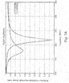
- FIGS. 7A and 7B schematically illustrate experimental data of the sensor for tissue characterization of the present invention.
- FIG. 7A illustrates a reflection coefficient amplitude of a reflection signal.
- FIG. 7B illustrates a reflection coefficient phase of a reflection signal.
- At least one of the amplitude and the phase may be used. Additionally, both may be used.
- FIGS. 7A and 7B illustrate the broadband nature of the resonator of the present invention. Defining a response as a change of at least 10% in the reflection coefficient amplitude of a reflection signal ( FIG. 7A ), it is noted that the range of the response in FIG. 7A is from about 180 to about 260 MHz. In the present example of FIG. 7A , the range is 80 MHz around a resonating value of 220 MHz.
- the broadband is often defined as ⁇ f/f, or in the present example, 80/220. Expressing the broadband in percentage leads to a value of 36%, or ⁇ 18%.
- the broadband may be as much as ⁇ 50%. Alternatively, it may be at least ⁇ 25%, or at least ⁇ 15%.
- the term “substantially” refers to ⁇ 10%.
Abstract
Description
Claims (26)
Priority Applications (1)
| Application Number | Priority Date | Filing Date | Title |
|---|---|---|---|
| US11/887,571 US7899515B2 (en) | 2005-03-29 | 2006-03-29 | Electromagnetic sensors for tissue characterization |
Applications Claiming Priority (3)
| Application Number | Priority Date | Filing Date | Title |
|---|---|---|---|
| US66584205P | 2005-03-29 | 2005-03-29 | |
| PCT/IL2006/000392 WO2006103665A2 (en) | 2005-03-29 | 2006-03-29 | Electromagnetic sensors for tissue characterization |
| US11/887,571 US7899515B2 (en) | 2005-03-29 | 2006-03-29 | Electromagnetic sensors for tissue characterization |
Publications (2)
| Publication Number | Publication Date |
|---|---|
| US20090062637A1 US20090062637A1 (en) | 2009-03-05 |
| US7899515B2 true US7899515B2 (en) | 2011-03-01 |
Family
ID=37053782
Family Applications (1)
| Application Number | Title | Priority Date | Filing Date |
|---|---|---|---|
| US11/887,571 Active 2027-09-10 US7899515B2 (en) | 2005-03-29 | 2006-03-29 | Electromagnetic sensors for tissue characterization |
Country Status (7)
| Country | Link |
|---|---|
| US (1) | US7899515B2 (en) |
| EP (1) | EP1890596B1 (en) |
| JP (1) | JP5308812B2 (en) |
| CN (2) | CN101991415B (en) |
| CA (1) | CA2603025C (en) |
| ES (1) | ES2434851T3 (en) |
| WO (1) | WO2006103665A2 (en) |
Cited By (6)
| Publication number | Priority date | Publication date | Assignee | Title |
|---|---|---|---|---|
| US20070032739A1 (en) * | 2005-08-04 | 2007-02-08 | Dune Medical Devices Ltd. | Device for forming an effective sensor-to-tissue contact |
| US20080154090A1 (en) * | 2005-01-04 | 2008-06-26 | Dune Medical Devices Ltd. | Endoscopic System for In-Vivo Procedures |
| US20080287750A1 (en) * | 2002-01-04 | 2008-11-20 | Dune Medical Devices Ltd. | Ergonomic probes |
| US20090187109A1 (en) * | 2001-11-19 | 2009-07-23 | Dune Medical Devices Ltd. | Method and apparatus for examining tissue for predefined target cells, particularly cancerous cells, and a probe useful in such method and apparatus |
| US9402582B1 (en) | 2014-04-21 | 2016-08-02 | Verily Life Sciences Llc | Smart surgical glove |
| US9526460B2 (en) | 2005-08-04 | 2016-12-27 | Dune Medical Devices Ltd. | Tissue-characterization probe with effective sensor-to-tissue contact |
Families Citing this family (28)
| Publication number | Priority date | Publication date | Assignee | Title |
|---|---|---|---|---|
| US8019411B2 (en) * | 2002-01-04 | 2011-09-13 | Dune Medical Devices Ltd. | Probes, systems, and methods for examining tissue according to the dielectric properties thereof |
| US8032211B2 (en) * | 2002-01-04 | 2011-10-04 | Dune Medical Devices Ltd. | Probes, systems, and methods for examining tissue according to the dielectric properties thereof |
| WO2005089065A2 (en) | 2004-03-23 | 2005-09-29 | Dune Medical Devices Ltd. | Clean margin assessment tool |
| US9750425B2 (en) | 2004-03-23 | 2017-09-05 | Dune Medical Devices Ltd. | Graphical user interfaces (GUI), methods and apparatus for data presentation |
| US7904145B2 (en) | 2004-03-23 | 2011-03-08 | Dune Medical Devices Ltd. | Clean margin assessment tool |
| US8588887B2 (en) | 2006-09-06 | 2013-11-19 | Innurvation, Inc. | Ingestible low power sensor device and system for communicating with same |
| EP2063785A4 (en) | 2006-09-06 | 2011-08-31 | Innurvation Inc | System and method for acoustic information exchange involving an ingestible low power capsule |
| US8147423B2 (en) | 2007-03-01 | 2012-04-03 | Dune Medical Devices, Ltd. | Tissue-characterization system and method |
| EP2178443B1 (en) | 2007-07-16 | 2015-07-08 | Dune Medical Devices Ltd. | Medical device for use in tissue characterization and treatment |
| US9757098B2 (en) | 2007-07-16 | 2017-09-12 | Dune Medical Devices Ltd. | Medical device and method for use in tissue characterization and treatment |
| US9999353B2 (en) | 2007-07-16 | 2018-06-19 | Dune Medical Devices Ltd. | Medical device and method for use in tissue characterization and treatment |
| US9901362B2 (en) | 2007-07-16 | 2018-02-27 | Dune Medical Devices Ltd. | Medical device and method for use in tissue characterization and treatment |
| CN101377983B (en) * | 2007-08-29 | 2012-03-14 | 博西华电器(江苏)有限公司 | Household appliance operation apparatus and indication unit operation method |
| US9197470B2 (en) | 2007-10-05 | 2015-11-24 | Innurvation, Inc. | Data transmission via multi-path channels using orthogonal multi-frequency signals with differential phase shift keying modulation |
| DE102008064405A1 (en) | 2008-06-02 | 2009-12-10 | Rohde & Schwarz Gmbh & Co. Kg | Measuring device and method for determining tissue parameters |
| US8617058B2 (en) | 2008-07-09 | 2013-12-31 | Innurvation, Inc. | Displaying image data from a scanner capsule |
| IN2012DN00937A (en) * | 2009-08-03 | 2015-04-03 | Dune Medical Devices Ltd | |
| EP2461755A4 (en) * | 2009-08-03 | 2017-07-12 | Dune Medical Devices Ltd. | Surgical tool |
| US9192353B2 (en) | 2009-10-27 | 2015-11-24 | Innurvation, Inc. | Data transmission via wide band acoustic channels |
| US8647259B2 (en) | 2010-03-26 | 2014-02-11 | Innurvation, Inc. | Ultrasound scanning capsule endoscope (USCE) |
| DK2800510T3 (en) * | 2012-01-05 | 2019-01-21 | Sensible Medical Innovations Ltd | ELECTROMAGNETIC (EM) PROBLEMS, PROCEDURES FOR USING SUCH EM PROBLEMS AND SYSTEMS USING SUCH ELECTROMAGNETIC EM PROBE |
| JP6470173B2 (en) | 2012-07-12 | 2019-02-13 | デューン メディカル デヴァイシズ リミテッドDune Medical Devices Ltd. | Medical device used for tissue characterization and treatment |
| TWI481385B (en) * | 2012-10-02 | 2015-04-21 | Univ Lunghwa Sci & Technology | Non - invasive blood glucose measurement circuit module |
| FI127021B (en) * | 2014-06-02 | 2017-09-29 | Senfit Oy | Sensor, measuring device and measuring method |
| CN105167223B (en) * | 2014-10-22 | 2016-11-30 | 北京至感传感器技术研究院有限公司 | For detecting the medicated bra of breast physiological change |
| CN105266213A (en) * | 2014-11-10 | 2016-01-27 | 北京至感传感器技术研究院有限公司 | Bra for checking breasts' physiological changes |
| CN105476081A (en) * | 2015-02-12 | 2016-04-13 | 北京至感传感器技术研究院有限公司 | Bra assembly |
| US11293963B2 (en) * | 2017-11-28 | 2022-04-05 | Nxp B.V. | Device for electromagnetic structural characterization |
Citations (116)
| Publication number | Priority date | Publication date | Assignee | Title |
|---|---|---|---|---|
| US3830224A (en) | 1972-12-19 | 1974-08-20 | Vanzetti Infrared Computer Sys | Means for detecting changes in the temperature of the skin |
| US4291708A (en) | 1977-11-02 | 1981-09-29 | Yeda Research & Development Co. Ltd. | Apparatus and method for detection of tumors in tissue |
| US4344440A (en) | 1980-04-01 | 1982-08-17 | Trygve Aaby | Microprobe for monitoring biophysical phenomena associated with cardiac and neural activity |
| US4458694A (en) | 1977-11-02 | 1984-07-10 | Yeda Research & Development Co., Ltd. | Apparatus and method for detection of tumors in tissue |
| US4537203A (en) | 1980-10-21 | 1985-08-27 | Tokyo Shibaura Denki Kabushiki Kaisha | Abnormal cell detecting device |
| US4539640A (en) | 1982-01-12 | 1985-09-03 | Tasc Ltd. | Reconstruction system and methods for impedance imaging |
| USRE32000E (en) | 1978-05-22 | 1985-10-08 | B.C.S.I. Laboratories, Inc. | Device for use in early detection of breast cancer |
| US4617939A (en) | 1982-04-30 | 1986-10-21 | The University Of Sheffield | Tomography |
| US4625171A (en) | 1983-02-14 | 1986-11-25 | Hitachi, Ltd. | Imaging apparatus using nuclear magnetic resonance |
| US4682594A (en) | 1985-03-11 | 1987-07-28 | Mcm Laboratories, Inc. | Probe-and-fire lasers |
| US4689567A (en) | 1984-06-01 | 1987-08-25 | Advanced Nmr Systems, Inc. | NMR Fourier imaging from multiple echoes |
| US4751464A (en) | 1987-05-04 | 1988-06-14 | Advanced Nmr Systems, Inc. | Cavity resonator with improved magnetic field uniformity for high frequency operation and reduced dielectric heating in NMR imaging devices |
| US4768513A (en) | 1986-04-21 | 1988-09-06 | Agency Of Industrial Science And Technology | Method and device for measuring and processing light |
| US4779624A (en) | 1986-05-21 | 1988-10-25 | Olympus Optical Co., Ltd. | Ultrasonic endoscope |
| US4785806A (en) | 1987-01-08 | 1988-11-22 | Yale University | Laser ablation process and apparatus |
| US5115137A (en) | 1989-02-22 | 1992-05-19 | Spectraphos Ab | Diagnosis by means of fluorescent light emission from tissue |
| US5143079A (en) | 1989-08-02 | 1992-09-01 | Yeda Research And Development Company Limited | Apparatus for detection of tumors in tissue |
| US5227730A (en) | 1992-09-14 | 1993-07-13 | Kdc Technology Corp. | Microwave needle dielectric sensors |
| US5277730A (en) | 1987-12-16 | 1994-01-11 | At&T Bell Laboratories | Methods of recoating spliced lengths of optical fibers |
| US5334941A (en) | 1992-09-14 | 1994-08-02 | Kdc Technology Corp. | Microwave reflection resonator sensors |
| US5383454A (en) | 1990-10-19 | 1995-01-24 | St. Louis University | System for indicating the position of a surgical probe within a head on an image of the head |
| US5442290A (en) | 1992-08-04 | 1995-08-15 | The Regents Of The University Of California | MRI gradient drive current control using all digital controller |
| US5482047A (en) | 1992-11-23 | 1996-01-09 | Advanced Technology Laboratories, Inc. | Intraoperative ultrasound probe |
| US5482041A (en) | 1992-06-05 | 1996-01-09 | Wilk; Peter J. | Medical investigation system and related method |
| US5558092A (en) | 1995-06-06 | 1996-09-24 | Imarx Pharmaceutical Corp. | Methods and apparatus for performing diagnostic and therapeutic ultrasound simultaneously |
| US5572132A (en) | 1995-08-15 | 1996-11-05 | Pulyer; Yuly M. | MRI probe for external imaging |
| US5630426A (en) | 1995-03-03 | 1997-05-20 | Neovision Corporation | Apparatus and method for characterization and treatment of tumors |
| DE19705260A1 (en) | 1996-02-20 | 1997-08-21 | Hauni Maschinenbau Ag | Detecting at least one characteristic of material by evaluating HF resonator tuning |
| US5678565A (en) | 1992-12-21 | 1997-10-21 | Artann Corporation | Ultrasonic elasticity imaging method and device |
| US5699804A (en) | 1995-06-07 | 1997-12-23 | Siemens Aktiengesellschaft | Therapy apparatus having a source of acoustic waves |
| US5704355A (en) | 1994-07-01 | 1998-01-06 | Bridges; Jack E. | Non-invasive system for breast cancer detection |
| US5727569A (en) | 1996-02-20 | 1998-03-17 | Cardiothoracic Systems, Inc. | Surgical devices for imposing a negative pressure to fix the position of cardiac tissue during surgery |
| US5735278A (en) | 1996-03-15 | 1998-04-07 | National Research Council Of Canada | Surgical procedure with magnetic resonance imaging |
| US5744971A (en) | 1994-09-09 | 1998-04-28 | Chan; Tsing Yee Amy | Device and apparatus for measuring dielectric properties of materials |
| US5758646A (en) | 1994-09-12 | 1998-06-02 | U.S. Philips Corporation | Magnetic resonance imaging method with pulse sequence optimization and device for such method |
| US5800350A (en) | 1993-11-01 | 1998-09-01 | Polartechnics, Limited | Apparatus for tissue type recognition |
| US5810742A (en) | 1994-10-24 | 1998-09-22 | Transcan Research & Development Co., Ltd. | Tissue characterization based on impedance images and on impedance measurements |
| US5821410A (en) | 1996-09-20 | 1998-10-13 | Regents Of The University Of California | Scanning tip microwave near field microscope |
| US5829437A (en) | 1994-07-01 | 1998-11-03 | Interstitial, Inc. | Microwave method and system to detect and locate cancers in heterogenous tissues |
| DE19734978A1 (en) | 1997-02-12 | 1999-02-18 | Hauni Maschinenbau Ag | Material characteristic determination method |
| US5884239A (en) | 1995-12-27 | 1999-03-16 | Romanik, Jr.; Carl J. | Optical system for accurate monitoring of the position and orientation of an object |
| US5900618A (en) | 1997-08-26 | 1999-05-04 | University Of Maryland | Near-field scanning microwave microscope having a transmission line with an open end |
| US5927284A (en) | 1995-09-20 | 1999-07-27 | Medtronic, Inc | Method and apparatus for temporarily immobilizing a local area of tissue |
| US6004263A (en) | 1996-03-13 | 1999-12-21 | Hihon Kohden Corporation | Endoscope with detachable operation unit and insertion unit |
| US6010455A (en) | 1995-11-27 | 2000-01-04 | Hill-Rom, Inc. | Skin perfusion evaluation apparatus |
| US6026323A (en) | 1997-03-20 | 2000-02-15 | Polartechnics Limited | Tissue diagnostic system |
| US6055451A (en) | 1997-12-12 | 2000-04-25 | Spectrx, Inc. | Apparatus and method for determining tissue characteristics |
| US6061589A (en) | 1994-07-01 | 2000-05-09 | Interstitial, Inc. | Microwave antenna for cancer detection system |
| US6064081A (en) | 1994-11-10 | 2000-05-16 | Lawrence Semiconductor Research Laboratory, Inc. | Silicon-germanium-carbon compositions and processes thereof |
| US6071239A (en) | 1997-10-27 | 2000-06-06 | Cribbs; Robert W. | Method and apparatus for lipolytic therapy using ultrasound energy |
| US6081738A (en) | 1998-01-15 | 2000-06-27 | Lumend, Inc. | Method and apparatus for the guided bypass of coronary occlusions |
| US6086534A (en) | 1997-03-07 | 2000-07-11 | Cardiogenesis Corporation | Apparatus and method of myocardial revascularization using ultrasonic pulse-echo distance ranging |
| US6090041A (en) | 1999-02-16 | 2000-07-18 | Regents Of The University Of California | vacuum actuated surgical retractor and methods |
| US6109270A (en) | 1997-02-04 | 2000-08-29 | The United States Of America As Represented By The Administrator Of The National Aeronautics And Space Administration | Multimodality instrument for tissue characterization |
| US6135968A (en) | 1997-09-10 | 2000-10-24 | Scantek Medical, Inc. | Differential temperature measuring device and method |
| US6167297A (en) | 1999-05-05 | 2000-12-26 | Benaron; David A. | Detecting, localizing, and targeting internal sites in vivo using optical contrast agents |
| US6173604B1 (en) | 1996-09-20 | 2001-01-16 | The Regents Of The University Of California | Scanning evanescent electro-magnetic microscope |
| US6203533B1 (en) | 1995-06-07 | 2001-03-20 | Asahi Kogaku Kogyo Kabushiki Kaisha | Treatment accessory for an endoscope |
| US6233479B1 (en) | 1998-09-15 | 2001-05-15 | The Regents Of The University Of California | Microwave hematoma detector |
| US6258576B1 (en) | 1996-06-19 | 2001-07-10 | Board Of Regents, The University Of Texas System | Diagnostic method and apparatus for cervical squamous intraepithelial lesions in vitro and in vivo using fluorescence spectroscopy |
| US6280704B1 (en) | 1993-07-30 | 2001-08-28 | Alliance Pharmaceutical Corp. | Ultrasonic imaging system utilizing a long-persistence contrast agent |
| US6287302B1 (en) | 1999-06-14 | 2001-09-11 | Fidus Medical Technology Corporation | End-firing microwave ablation instrument with horn reflection device |
| US6315981B1 (en) | 1989-12-22 | 2001-11-13 | Imarx Therapeutics, Inc. | Gas filled microspheres as magnetic resonance imaging contrast agents |
| US6321106B1 (en) | 1996-11-05 | 2001-11-20 | Jerome Lemelson | System and method for treating select tissue in a living being |
| US20010051774A1 (en) | 2000-02-28 | 2001-12-13 | Peter Littrup | Multidimensional bioelectrical tissue analyzer |
| US6331166B1 (en) | 1998-03-03 | 2001-12-18 | Senorx, Inc. | Breast biopsy system and method |
| US6370426B1 (en) | 1999-04-20 | 2002-04-09 | Nova Technology Corporation | Method and apparatus for measuring relative hydration of a substrate |
| US6375634B1 (en) | 1997-11-19 | 2002-04-23 | Oncology Innovations, Inc. | Apparatus and method to encapsulate, kill and remove malignancies, including selectively increasing absorption of x-rays and increasing free-radical damage to residual tumors targeted by ionizing and non-ionizing radiation therapy |
| US6377841B1 (en) | 2000-03-31 | 2002-04-23 | Vanderbilt University | Tumor demarcation using optical spectroscopy |
| US6380747B1 (en) | 1998-05-12 | 2002-04-30 | Jentek Sensors, Inc. | Methods for processing, optimization, calibration and display of measured dielectrometry signals using property estimation grids |
| US20020055754A1 (en) | 1999-10-05 | 2002-05-09 | Kevin Ranucci | Utrasonic probe device with rapid attachment and detachment means |
| US20020059938A1 (en) | 2000-02-18 | 2002-05-23 | Fogarty Thomas J. | Device for accurately marking tissue |
| US6397095B1 (en) | 1999-03-01 | 2002-05-28 | The Trustees Of The University Of Pennsylvania | Magnetic resonance—electrical impedance tomography |
| US6405733B1 (en) | 2000-02-18 | 2002-06-18 | Thomas J. Fogarty | Device for accurately marking tissue |
| US6411103B1 (en) | 1999-06-03 | 2002-06-25 | Hauni Maschinenbau Ag | Stray-field sensor |
| US20020120265A1 (en) | 1999-12-23 | 2002-08-29 | Mayo Foundation For Medical Education And Research | Symmetric conization electrocautery device |
| US6500112B1 (en) | 1994-03-30 | 2002-12-31 | Brava, Llc | Vacuum dome with supporting rim and rim cushion |
| US20030036674A1 (en) | 2001-07-26 | 2003-02-20 | Bouton Chad Edward | Electromagnetic sensors for biological tissue applications and methods for their use |
| US20030045798A1 (en) | 2001-09-04 | 2003-03-06 | Richard Hular | Multisensor probe for tissue identification |
| US6530944B2 (en) | 2000-02-08 | 2003-03-11 | Rice University | Optically-active nanoparticles for use in therapeutic and diagnostic methods |
| US20030062897A1 (en) | 1997-11-26 | 2003-04-03 | Belt Kenneth W. | Peripheral vascular array |
| US6544185B2 (en) | 2000-10-23 | 2003-04-08 | Valentino Montegrande | Ultrasound imaging marker and method of use |
| US6546787B1 (en) | 1999-03-25 | 2003-04-15 | Regents Of The University Of Minnesota | Means and method for modeling and treating specific tissue structures |
| JP2003516214A (en) | 1999-12-08 | 2003-05-13 | トップスピン メディカル (イスラエル) リミテッド | Magnetic resonance imaging device |
| US6592520B1 (en) | 2001-07-31 | 2003-07-15 | Koninklijke Philips Electronics N.V. | Intravascular ultrasound imaging apparatus and method |
| US6597185B1 (en) | 2000-09-20 | 2003-07-22 | Neocera, Inc. | Apparatus for localized measurements of complex permittivity of a material |
| US20030138378A1 (en) | 2001-11-19 | 2003-07-24 | Dune Medical Devices Ltd. | Method and apparatus for examining tissue for predefined target cells, particularly cancerous cells, and a probe useful in such method and apparatus |
| US20030146814A1 (en) | 2000-03-06 | 2003-08-07 | Wiltshire Michael Charles Keogh | Structure with switchable magnetic properties |
| US20030163037A1 (en) | 1992-08-14 | 2003-08-28 | British Telecommunications Public Limited Company | Surgical navigation |
| US20030171664A1 (en) | 2000-02-25 | 2003-09-11 | Wendlandt Jeffrey M | Diagnostic catheter using a vacuum for tissue positioning |
| US20030187366A1 (en) | 2002-01-04 | 2003-10-02 | Dune Medical Devices Ltd. | Method and system for examining tissue according to the dielectric properties thereof |
| US20030187347A1 (en) | 2001-02-15 | 2003-10-02 | Robin Medical Inc. | Endoscopic examining apparatus particularly useful in MRI, a probe useful in such apparatus, and a method of making such probe |
| US20030199753A1 (en) | 2002-04-23 | 2003-10-23 | Ethicon Endo-Surgery | MRI compatible biopsy device with detachable probe |
| US20030216648A1 (en) | 2002-05-14 | 2003-11-20 | Lizzi Frederic L. | Ultrasound method and system |
| US20030229343A1 (en) | 2002-06-06 | 2003-12-11 | Albrecht Thomas E. | Device for removal of tissue lesions |
| US6671540B1 (en) | 1990-08-10 | 2003-12-30 | Daryl W. Hochman | Methods and systems for detecting abnormal tissue using spectroscopic techniques |
| US20040065158A1 (en) | 2001-03-06 | 2004-04-08 | Schrepfer Thomas W. | Method and device for determining the concentration of a substance in body liquid |
| US6722371B1 (en) | 2000-02-18 | 2004-04-20 | Thomas J. Fogarty | Device for accurately marking tissue |
| US6741077B2 (en) | 2000-08-25 | 2004-05-25 | Yamagata Public Corporation For The Development Of Industry | Electron spin resonance measurement method and measurement device for measuring ESR within the interior of large samples |
| US6766185B2 (en) | 2000-05-22 | 2004-07-20 | The Board Of Trustees Of The Leland Stanford Junior University | Transmission line techniques for MRI catheter coil miniaturization and tuning |
| US20040254457A1 (en) | 2003-06-02 | 2004-12-16 | Van Der Weide Daniel Warren | Apparatus and method for near-field imaging of tissue |
| US20050021019A1 (en) | 2003-07-24 | 2005-01-27 | Dune Medical Devices Ltd. | Method and apparatus for examining a substance, particularly tissue, to characterize its type |
| US20050107717A1 (en) | 2003-10-02 | 2005-05-19 | Omron Healthcare Co., Ltd, | Method and device for calculating visceral fat |
| US6909084B2 (en) | 2000-08-31 | 2005-06-21 | Toudai Tlo, Ltd | Optical tactile sensor having a transparent elastic tactile portion |
| US6936003B2 (en) | 2002-10-29 | 2005-08-30 | Given Imaging Ltd | In-vivo extendable element device and system, and method of use |
| US6962587B2 (en) | 2000-07-25 | 2005-11-08 | Rita Medical Systems, Inc. | Method for detecting and treating tumors using localized impedance measurement |
| US20060253107A1 (en) | 2004-03-23 | 2006-11-09 | Dune Medical Devices Ltd. | Clean margin assessment tool |
| US20060264738A1 (en) | 2003-07-24 | 2006-11-23 | Dune Medical Devices Ltd. | Method and apparatus for examining a substance, particularly tissue, to characterize its type |
| US20070032747A1 (en) | 2005-08-04 | 2007-02-08 | Dune Medical Devices Ltd. | Tissue-characterization probe with effective sensor-to-tissue contact |
| US20070032739A1 (en) | 2005-08-04 | 2007-02-08 | Dune Medical Devices Ltd. | Device for forming an effective sensor-to-tissue contact |
| US20070179397A1 (en) | 2002-01-04 | 2007-08-02 | Dune Medical Devices Ltd. | Probes, systems, and methods for examining tissue according to the dielectric properties thereof |
| US20070255169A1 (en) | 2001-11-19 | 2007-11-01 | Dune Medical Devices Ltd. | Clean margin assessment tool |
| US20080021343A1 (en) | 2002-01-04 | 2008-01-24 | Dune Medical Devices Ltd. | Probes, systems, and methods for examining tissue according to the dielectric properties thereof |
| US20080039742A1 (en) | 2004-03-23 | 2008-02-14 | Dune Medical Devices Ltd. | Clean margin assessment tool |
| US20080154090A1 (en) | 2005-01-04 | 2008-06-26 | Dune Medical Devices Ltd. | Endoscopic System for In-Vivo Procedures |
| US20080287750A1 (en) | 2002-01-04 | 2008-11-20 | Dune Medical Devices Ltd. | Ergonomic probes |
Family Cites Families (10)
| Publication number | Priority date | Publication date | Assignee | Title |
|---|---|---|---|---|
| JPS6018768A (en) * | 1983-07-12 | 1985-01-30 | Katsuo Ebara | Non-contact type conductivity/dielectric constant simultaneous measuring sensor |
| US4841249A (en) * | 1986-10-28 | 1989-06-20 | Siemens Aktiengesellschaft | Truncated cone shaped surface resonator for nuclear magnetic resonance tomography |
| JPS63118648A (en) * | 1986-11-07 | 1988-05-23 | Jeol Ltd | Electron spin resonating device provided with loop gap resonator |
| JP2740528B2 (en) * | 1988-10-20 | 1998-04-15 | 学校法人東海大学 | Physical property measurement device |
| JP2946843B2 (en) * | 1991-07-08 | 1999-09-06 | 東陶機器株式会社 | A method for judging the degree of ripening of fruits and the like and a sensor for judging the degree of ripening |
| JPH0792115A (en) * | 1993-09-24 | 1995-04-07 | Junkosha Co Ltd | Electron spin resonator |
| JP3369829B2 (en) * | 1996-01-17 | 2003-01-20 | 花王株式会社 | Moisture measurement device |
| JPH11304764A (en) * | 1998-04-27 | 1999-11-05 | Omron Corp | Moisture sensor |
| JP3794848B2 (en) * | 1998-12-28 | 2006-07-12 | 三井化学株式会社 | Method and apparatus for measuring dielectric constant in millimeter wave band |
| US6556013B2 (en) * | 2001-03-09 | 2003-04-29 | Bruker Biospin Corp. | Planar NMR coils with localized field-generating and capacitive elements |
-
2006
- 2006-03-29 EP EP06728196.4A patent/EP1890596B1/en active Active
- 2006-03-29 US US11/887,571 patent/US7899515B2/en active Active
- 2006-03-29 WO PCT/IL2006/000392 patent/WO2006103665A2/en active Search and Examination
- 2006-03-29 JP JP2008503679A patent/JP5308812B2/en active Active
- 2006-03-29 CN CN2010105281130A patent/CN101991415B/en active Active
- 2006-03-29 CN CN2006800190264A patent/CN101184435B/en active Active
- 2006-03-29 ES ES06728196T patent/ES2434851T3/en active Active
- 2006-03-29 CA CA2603025A patent/CA2603025C/en active Active
Patent Citations (136)
| Publication number | Priority date | Publication date | Assignee | Title |
|---|---|---|---|---|
| US3830224A (en) | 1972-12-19 | 1974-08-20 | Vanzetti Infrared Computer Sys | Means for detecting changes in the temperature of the skin |
| US4458694A (en) | 1977-11-02 | 1984-07-10 | Yeda Research & Development Co., Ltd. | Apparatus and method for detection of tumors in tissue |
| US4291708A (en) | 1977-11-02 | 1981-09-29 | Yeda Research & Development Co. Ltd. | Apparatus and method for detection of tumors in tissue |
| USRE32000E (en) | 1978-05-22 | 1985-10-08 | B.C.S.I. Laboratories, Inc. | Device for use in early detection of breast cancer |
| US4344440A (en) | 1980-04-01 | 1982-08-17 | Trygve Aaby | Microprobe for monitoring biophysical phenomena associated with cardiac and neural activity |
| US4537203A (en) | 1980-10-21 | 1985-08-27 | Tokyo Shibaura Denki Kabushiki Kaisha | Abnormal cell detecting device |
| US4539640A (en) | 1982-01-12 | 1985-09-03 | Tasc Ltd. | Reconstruction system and methods for impedance imaging |
| US4617939A (en) | 1982-04-30 | 1986-10-21 | The University Of Sheffield | Tomography |
| US4625171A (en) | 1983-02-14 | 1986-11-25 | Hitachi, Ltd. | Imaging apparatus using nuclear magnetic resonance |
| US4689567A (en) | 1984-06-01 | 1987-08-25 | Advanced Nmr Systems, Inc. | NMR Fourier imaging from multiple echoes |
| US4682594A (en) | 1985-03-11 | 1987-07-28 | Mcm Laboratories, Inc. | Probe-and-fire lasers |
| US4768513A (en) | 1986-04-21 | 1988-09-06 | Agency Of Industrial Science And Technology | Method and device for measuring and processing light |
| US4779624A (en) | 1986-05-21 | 1988-10-25 | Olympus Optical Co., Ltd. | Ultrasonic endoscope |
| US4785806A (en) | 1987-01-08 | 1988-11-22 | Yale University | Laser ablation process and apparatus |
| US4751464A (en) | 1987-05-04 | 1988-06-14 | Advanced Nmr Systems, Inc. | Cavity resonator with improved magnetic field uniformity for high frequency operation and reduced dielectric heating in NMR imaging devices |
| US5277730A (en) | 1987-12-16 | 1994-01-11 | At&T Bell Laboratories | Methods of recoating spliced lengths of optical fibers |
| US5115137A (en) | 1989-02-22 | 1992-05-19 | Spectraphos Ab | Diagnosis by means of fluorescent light emission from tissue |
| US5143079A (en) | 1989-08-02 | 1992-09-01 | Yeda Research And Development Company Limited | Apparatus for detection of tumors in tissue |
| US6315981B1 (en) | 1989-12-22 | 2001-11-13 | Imarx Therapeutics, Inc. | Gas filled microspheres as magnetic resonance imaging contrast agents |
| US6671540B1 (en) | 1990-08-10 | 2003-12-30 | Daryl W. Hochman | Methods and systems for detecting abnormal tissue using spectroscopic techniques |
| US5383454A (en) | 1990-10-19 | 1995-01-24 | St. Louis University | System for indicating the position of a surgical probe within a head on an image of the head |
| US5383454B1 (en) | 1990-10-19 | 1996-12-31 | Univ St Louis | System for indicating the position of a surgical probe within a head on an image of the head |
| US5482041A (en) | 1992-06-05 | 1996-01-09 | Wilk; Peter J. | Medical investigation system and related method |
| US5442290A (en) | 1992-08-04 | 1995-08-15 | The Regents Of The University Of California | MRI gradient drive current control using all digital controller |
| US20030163037A1 (en) | 1992-08-14 | 2003-08-28 | British Telecommunications Public Limited Company | Surgical navigation |
| US5227730A (en) | 1992-09-14 | 1993-07-13 | Kdc Technology Corp. | Microwave needle dielectric sensors |
| US5334941A (en) | 1992-09-14 | 1994-08-02 | Kdc Technology Corp. | Microwave reflection resonator sensors |
| US5482047A (en) | 1992-11-23 | 1996-01-09 | Advanced Technology Laboratories, Inc. | Intraoperative ultrasound probe |
| US5678565A (en) | 1992-12-21 | 1997-10-21 | Artann Corporation | Ultrasonic elasticity imaging method and device |
| US6280704B1 (en) | 1993-07-30 | 2001-08-28 | Alliance Pharmaceutical Corp. | Ultrasonic imaging system utilizing a long-persistence contrast agent |
| US5800350A (en) | 1993-11-01 | 1998-09-01 | Polartechnics, Limited | Apparatus for tissue type recognition |
| US6500112B1 (en) | 1994-03-30 | 2002-12-31 | Brava, Llc | Vacuum dome with supporting rim and rim cushion |
| US6061589A (en) | 1994-07-01 | 2000-05-09 | Interstitial, Inc. | Microwave antenna for cancer detection system |
| US5704355A (en) | 1994-07-01 | 1998-01-06 | Bridges; Jack E. | Non-invasive system for breast cancer detection |
| US5829437A (en) | 1994-07-01 | 1998-11-03 | Interstitial, Inc. | Microwave method and system to detect and locate cancers in heterogenous tissues |
| US5807257A (en) | 1994-07-01 | 1998-09-15 | Interstitial, Inc. | Breast cancer detection, imaging and screening by electromagnetic millimeter waves |
| US5744971A (en) | 1994-09-09 | 1998-04-28 | Chan; Tsing Yee Amy | Device and apparatus for measuring dielectric properties of materials |
| US5758646A (en) | 1994-09-12 | 1998-06-02 | U.S. Philips Corporation | Magnetic resonance imaging method with pulse sequence optimization and device for such method |
| US6055452A (en) | 1994-10-24 | 2000-04-25 | Transcan Research & Development Co., Ltd. | Tissue characterization based on impedance images and on impedance measurements |
| US5810742A (en) | 1994-10-24 | 1998-09-22 | Transcan Research & Development Co., Ltd. | Tissue characterization based on impedance images and on impedance measurements |
| US6308097B1 (en) | 1994-10-24 | 2001-10-23 | Transscan Medical Ltd. | Tissue characterization based on impedance images and on impedance measurements |
| US6064081A (en) | 1994-11-10 | 2000-05-16 | Lawrence Semiconductor Research Laboratory, Inc. | Silicon-germanium-carbon compositions and processes thereof |
| US5630426A (en) | 1995-03-03 | 1997-05-20 | Neovision Corporation | Apparatus and method for characterization and treatment of tumors |
| US5558092A (en) | 1995-06-06 | 1996-09-24 | Imarx Pharmaceutical Corp. | Methods and apparatus for performing diagnostic and therapeutic ultrasound simultaneously |
| US6203533B1 (en) | 1995-06-07 | 2001-03-20 | Asahi Kogaku Kogyo Kabushiki Kaisha | Treatment accessory for an endoscope |
| US5699804A (en) | 1995-06-07 | 1997-12-23 | Siemens Aktiengesellschaft | Therapy apparatus having a source of acoustic waves |
| US5572132A (en) | 1995-08-15 | 1996-11-05 | Pulyer; Yuly M. | MRI probe for external imaging |
| US5927284A (en) | 1995-09-20 | 1999-07-27 | Medtronic, Inc | Method and apparatus for temporarily immobilizing a local area of tissue |
| US6010455A (en) | 1995-11-27 | 2000-01-04 | Hill-Rom, Inc. | Skin perfusion evaluation apparatus |
| US5884239A (en) | 1995-12-27 | 1999-03-16 | Romanik, Jr.; Carl J. | Optical system for accurate monitoring of the position and orientation of an object |
| DE19705260A1 (en) | 1996-02-20 | 1997-08-21 | Hauni Maschinenbau Ag | Detecting at least one characteristic of material by evaluating HF resonator tuning |
| US5727569A (en) | 1996-02-20 | 1998-03-17 | Cardiothoracic Systems, Inc. | Surgical devices for imposing a negative pressure to fix the position of cardiac tissue during surgery |
| US6004263A (en) | 1996-03-13 | 1999-12-21 | Hihon Kohden Corporation | Endoscope with detachable operation unit and insertion unit |
| US5735278A (en) | 1996-03-15 | 1998-04-07 | National Research Council Of Canada | Surgical procedure with magnetic resonance imaging |
| US6258576B1 (en) | 1996-06-19 | 2001-07-10 | Board Of Regents, The University Of Texas System | Diagnostic method and apparatus for cervical squamous intraepithelial lesions in vitro and in vivo using fluorescence spectroscopy |
| US6173604B1 (en) | 1996-09-20 | 2001-01-16 | The Regents Of The University Of California | Scanning evanescent electro-magnetic microscope |
| US5821410A (en) | 1996-09-20 | 1998-10-13 | Regents Of The University Of California | Scanning tip microwave near field microscope |
| US6321106B1 (en) | 1996-11-05 | 2001-11-20 | Jerome Lemelson | System and method for treating select tissue in a living being |
| US6109270A (en) | 1997-02-04 | 2000-08-29 | The United States Of America As Represented By The Administrator Of The National Aeronautics And Space Administration | Multimodality instrument for tissue characterization |
| DE19734978A1 (en) | 1997-02-12 | 1999-02-18 | Hauni Maschinenbau Ag | Material characteristic determination method |
| US6086534A (en) | 1997-03-07 | 2000-07-11 | Cardiogenesis Corporation | Apparatus and method of myocardial revascularization using ultrasonic pulse-echo distance ranging |
| US6026323A (en) | 1997-03-20 | 2000-02-15 | Polartechnics Limited | Tissue diagnostic system |
| US5900618A (en) | 1997-08-26 | 1999-05-04 | University Of Maryland | Near-field scanning microwave microscope having a transmission line with an open end |
| US6135968A (en) | 1997-09-10 | 2000-10-24 | Scantek Medical, Inc. | Differential temperature measuring device and method |
| US6071239A (en) | 1997-10-27 | 2000-06-06 | Cribbs; Robert W. | Method and apparatus for lipolytic therapy using ultrasound energy |
| US6375634B1 (en) | 1997-11-19 | 2002-04-23 | Oncology Innovations, Inc. | Apparatus and method to encapsulate, kill and remove malignancies, including selectively increasing absorption of x-rays and increasing free-radical damage to residual tumors targeted by ionizing and non-ionizing radiation therapy |
| US6677755B2 (en) | 1997-11-26 | 2004-01-13 | Medrad, Inc. | Circuit for selectively enabling and disabling coils of a multi-coil array |
| US6747454B2 (en) | 1997-11-26 | 2004-06-08 | Medrad, Inc. | Array of coils for use in imaging the vasculature of a patient |
| US20030062897A1 (en) | 1997-11-26 | 2003-04-03 | Belt Kenneth W. | Peripheral vascular array |
| US20030117140A1 (en) | 1997-11-26 | 2003-06-26 | Belt Kenneth W. | Peripheral vascular array |
| US6055451A (en) | 1997-12-12 | 2000-04-25 | Spectrx, Inc. | Apparatus and method for determining tissue characteristics |
| US6081738A (en) | 1998-01-15 | 2000-06-27 | Lumend, Inc. | Method and apparatus for the guided bypass of coronary occlusions |
| US6699206B2 (en) | 1998-03-03 | 2004-03-02 | Senorx, Inc. | Breast biopsy system and methods |
| US20050010131A1 (en) | 1998-03-03 | 2005-01-13 | Senorx, Inc. | Breast biopsy system and methods |
| US20020068880A1 (en) | 1998-03-03 | 2002-06-06 | Senorx Inc. | Breast biopsy system and methods |
| US6331166B1 (en) | 1998-03-03 | 2001-12-18 | Senorx, Inc. | Breast biopsy system and method |
| US6380747B1 (en) | 1998-05-12 | 2002-04-30 | Jentek Sensors, Inc. | Methods for processing, optimization, calibration and display of measured dielectrometry signals using property estimation grids |
| US6233479B1 (en) | 1998-09-15 | 2001-05-15 | The Regents Of The University Of California | Microwave hematoma detector |
| US6090041A (en) | 1999-02-16 | 2000-07-18 | Regents Of The University Of California | vacuum actuated surgical retractor and methods |
| US6397095B1 (en) | 1999-03-01 | 2002-05-28 | The Trustees Of The University Of Pennsylvania | Magnetic resonance—electrical impedance tomography |
| US6546787B1 (en) | 1999-03-25 | 2003-04-15 | Regents Of The University Of Minnesota | Means and method for modeling and treating specific tissue structures |
| US6370426B1 (en) | 1999-04-20 | 2002-04-09 | Nova Technology Corporation | Method and apparatus for measuring relative hydration of a substrate |
| US6167297A (en) | 1999-05-05 | 2000-12-26 | Benaron; David A. | Detecting, localizing, and targeting internal sites in vivo using optical contrast agents |
| US6411103B1 (en) | 1999-06-03 | 2002-06-25 | Hauni Maschinenbau Ag | Stray-field sensor |
| US6287302B1 (en) | 1999-06-14 | 2001-09-11 | Fidus Medical Technology Corporation | End-firing microwave ablation instrument with horn reflection device |
| US20020055754A1 (en) | 1999-10-05 | 2002-05-09 | Kevin Ranucci | Utrasonic probe device with rapid attachment and detachment means |
| US6695782B2 (en) | 1999-10-05 | 2004-02-24 | Omnisonics Medical Technologies, Inc. | Ultrasonic probe device with rapid attachment and detachment means |
| JP2003516214A (en) | 1999-12-08 | 2003-05-13 | トップスピン メディカル (イスラエル) リミテッド | Magnetic resonance imaging device |
| US20020120265A1 (en) | 1999-12-23 | 2002-08-29 | Mayo Foundation For Medical Education And Research | Symmetric conization electrocautery device |
| US6530944B2 (en) | 2000-02-08 | 2003-03-11 | Rice University | Optically-active nanoparticles for use in therapeutic and diagnostic methods |
| US6722371B1 (en) | 2000-02-18 | 2004-04-20 | Thomas J. Fogarty | Device for accurately marking tissue |
| US6405733B1 (en) | 2000-02-18 | 2002-06-18 | Thomas J. Fogarty | Device for accurately marking tissue |
| US20040168692A1 (en) | 2000-02-18 | 2004-09-02 | Thomas Fogarty | Device for accurately marking tissue |
| US6564806B1 (en) | 2000-02-18 | 2003-05-20 | Thomas J. Fogarty | Device for accurately marking tissue |
| US6752154B2 (en) | 2000-02-18 | 2004-06-22 | Thomas J. Fogarty | Device for accurately marking tissue |
| US20020059938A1 (en) | 2000-02-18 | 2002-05-23 | Fogarty Thomas J. | Device for accurately marking tissue |
| US20030171664A1 (en) | 2000-02-25 | 2003-09-11 | Wendlandt Jeffrey M | Diagnostic catheter using a vacuum for tissue positioning |
| US6728565B2 (en) | 2000-02-25 | 2004-04-27 | Scimed Life Systems, Inc. | Diagnostic catheter using a vacuum for tissue positioning |
| US20010051774A1 (en) | 2000-02-28 | 2001-12-13 | Peter Littrup | Multidimensional bioelectrical tissue analyzer |
| US20030146814A1 (en) | 2000-03-06 | 2003-08-07 | Wiltshire Michael Charles Keogh | Structure with switchable magnetic properties |
| US6377841B1 (en) | 2000-03-31 | 2002-04-23 | Vanderbilt University | Tumor demarcation using optical spectroscopy |
| US6766185B2 (en) | 2000-05-22 | 2004-07-20 | The Board Of Trustees Of The Leland Stanford Junior University | Transmission line techniques for MRI catheter coil miniaturization and tuning |
| US6962587B2 (en) | 2000-07-25 | 2005-11-08 | Rita Medical Systems, Inc. | Method for detecting and treating tumors using localized impedance measurement |
| US6741077B2 (en) | 2000-08-25 | 2004-05-25 | Yamagata Public Corporation For The Development Of Industry | Electron spin resonance measurement method and measurement device for measuring ESR within the interior of large samples |
| US6909084B2 (en) | 2000-08-31 | 2005-06-21 | Toudai Tlo, Ltd | Optical tactile sensor having a transparent elastic tactile portion |
| US6597185B1 (en) | 2000-09-20 | 2003-07-22 | Neocera, Inc. | Apparatus for localized measurements of complex permittivity of a material |
| US6544185B2 (en) | 2000-10-23 | 2003-04-08 | Valentino Montegrande | Ultrasound imaging marker and method of use |
| US20030187347A1 (en) | 2001-02-15 | 2003-10-02 | Robin Medical Inc. | Endoscopic examining apparatus particularly useful in MRI, a probe useful in such apparatus, and a method of making such probe |
| US20040065158A1 (en) | 2001-03-06 | 2004-04-08 | Schrepfer Thomas W. | Method and device for determining the concentration of a substance in body liquid |
| US20030036674A1 (en) | 2001-07-26 | 2003-02-20 | Bouton Chad Edward | Electromagnetic sensors for biological tissue applications and methods for their use |
| US6592520B1 (en) | 2001-07-31 | 2003-07-15 | Koninklijke Philips Electronics N.V. | Intravascular ultrasound imaging apparatus and method |
| US20030045798A1 (en) | 2001-09-04 | 2003-03-06 | Richard Hular | Multisensor probe for tissue identification |
| US20070255169A1 (en) | 2001-11-19 | 2007-11-01 | Dune Medical Devices Ltd. | Clean margin assessment tool |
| US20030138378A1 (en) | 2001-11-19 | 2003-07-24 | Dune Medical Devices Ltd. | Method and apparatus for examining tissue for predefined target cells, particularly cancerous cells, and a probe useful in such method and apparatus |
| US20070260156A1 (en) | 2001-11-19 | 2007-11-08 | Dune Medical Devices Ltd | Method and apparatus for examining tissue for predefined target cells, particularly cancerous cells, and a probe useful in such method and apparatus |
| US6813515B2 (en) | 2002-01-04 | 2004-11-02 | Dune Medical Devices Ltd. | Method and system for examining tissue according to the dielectric properties thereof |
| US20080021343A1 (en) | 2002-01-04 | 2008-01-24 | Dune Medical Devices Ltd. | Probes, systems, and methods for examining tissue according to the dielectric properties thereof |
| US20030187366A1 (en) | 2002-01-04 | 2003-10-02 | Dune Medical Devices Ltd. | Method and system for examining tissue according to the dielectric properties thereof |
| US20080287750A1 (en) | 2002-01-04 | 2008-11-20 | Dune Medical Devices Ltd. | Ergonomic probes |
| US20070179397A1 (en) | 2002-01-04 | 2007-08-02 | Dune Medical Devices Ltd. | Probes, systems, and methods for examining tissue according to the dielectric properties thereof |
| US7184824B2 (en) | 2002-01-04 | 2007-02-27 | Dune Medical Devices Ltd. | Method and system for examining tissue according to the dielectric properties thereof |
| US20030199753A1 (en) | 2002-04-23 | 2003-10-23 | Ethicon Endo-Surgery | MRI compatible biopsy device with detachable probe |
| US20030216648A1 (en) | 2002-05-14 | 2003-11-20 | Lizzi Frederic L. | Ultrasound method and system |
| US20030229343A1 (en) | 2002-06-06 | 2003-12-11 | Albrecht Thomas E. | Device for removal of tissue lesions |
| US6840948B2 (en) | 2002-06-06 | 2005-01-11 | Ethicon-Endo Surgery, Inc. | Device for removal of tissue lesions |
| US6936003B2 (en) | 2002-10-29 | 2005-08-30 | Given Imaging Ltd | In-vivo extendable element device and system, and method of use |
| US20040254457A1 (en) | 2003-06-02 | 2004-12-16 | Van Der Weide Daniel Warren | Apparatus and method for near-field imaging of tissue |
| US20050021019A1 (en) | 2003-07-24 | 2005-01-27 | Dune Medical Devices Ltd. | Method and apparatus for examining a substance, particularly tissue, to characterize its type |
| US20060264738A1 (en) | 2003-07-24 | 2006-11-23 | Dune Medical Devices Ltd. | Method and apparatus for examining a substance, particularly tissue, to characterize its type |
| US7082325B2 (en) | 2003-07-24 | 2006-07-25 | Dune Medical Devices Ltd. | Method and apparatus for examining a substance, particularly tissue, to characterize its type |
| US20050107717A1 (en) | 2003-10-02 | 2005-05-19 | Omron Healthcare Co., Ltd, | Method and device for calculating visceral fat |
| US20080039742A1 (en) | 2004-03-23 | 2008-02-14 | Dune Medical Devices Ltd. | Clean margin assessment tool |
| US20060253107A1 (en) | 2004-03-23 | 2006-11-09 | Dune Medical Devices Ltd. | Clean margin assessment tool |
| US20080154090A1 (en) | 2005-01-04 | 2008-06-26 | Dune Medical Devices Ltd. | Endoscopic System for In-Vivo Procedures |
| US20070032739A1 (en) | 2005-08-04 | 2007-02-08 | Dune Medical Devices Ltd. | Device for forming an effective sensor-to-tissue contact |
| US20070032747A1 (en) | 2005-08-04 | 2007-02-08 | Dune Medical Devices Ltd. | Tissue-characterization probe with effective sensor-to-tissue contact |
Non-Patent Citations (71)
| Title |
|---|
| Brown "A Survey of Image Registration Techniques", ACM Computing Surveys, 24(4): 325-376, 1992. |
| Burdette et al. "In Vivo Probe Measurement Technique for Determining Dielectric Properties at VFW Through Microwave Frequencies", IEEE Transactions on Microwave Theory & Techniques, MTT-28(4): 414-427, 1980. |
| Communication Pursuant to Article 94(3) EPC Dated Mar. 15, 2010 From the European Patent Office Re.: Application No. 06700052.1. |
| Communication Pursuant to Article 94(3) EPC Dated Oct. 7, 2009 From the European Patent Office Re.: Application No. 06728196.4. |
| Communication Pursuant to Article 94(3) EPC Dated Sep. 27, 2010 From the European Patent Office Re.: Application No. 06728196.4. |
| Communication Pursuant to Article 96(2) EPC Dated Aug. 10, 2006 From the European Patent Office Re.: Application No. 02795418.9. |
| Communication Pursuant to Article 96(2) EPC Dated Jan. 12, 2006 From the European Patent Office Re.: Application No. 02795418.9. |
| Communication Relating to the Results of the Partial International Search Dated Sep. 1, 2008 From the International Searching Authority Re.: Application No. PCT/IL2008/000406. |
| Examination Report Dated Nov. 18, 2008 From the Government of India, Patent Office Re.: Application No. 668/CHENP/2006. |
| International Preliminary Report on Patentability Dated Apr. 26, 2007 From the International Bureau of WIPO Re.: Application No. PCT/IL2005/000330. |
| International Preliminary Report on Patentability Dated Feb. 4, 2008 From the International Preliminary Examining Authority Re.: Application No. PCT/IL06/00392. |
| International Preliminary Report on Patentability Dated Jan. 22, 2009 From the International Bureau of WIPO Re.: Application No. PCT/IL2006/000908. |
| International Preliminary Report on Patentability Dated Nov. 12, 2009 From the International Bureau of WIPO Re.: Application No. PCT/IL2008/000406. |
| International Preliminary Report on Patentatbility Dated Aug. 9, 2007 From the International Bureau of WIPO Re.: Applicaiton No. PCT/IL2006/000015. |
| International Search Report Dated Nov. 27, 2008 From the International Searching Authority Re.: Application No. PCT/IL2008/000406. |
| Misra et al. "Noninvasive Electrical Characterization of Materials at Microwave Frequencies Using an Open-Ended Coaxial Line: Test of an Improved Calibration Technique", IEEE Transactions on Microwave Theory & Techniques, 38(1): 8-13, 1990. |
| Mosig et al. "Reflection of an Open-Ended Coaxial Line", IEEE Transactions on Instrumentation & Measurement, IM-30(1): 46-51, 1981. |
| Notice of Allowance Dated Jun. 29, 2010 From the US Patent and Trademark Office Re.: U.S. Appl. No. 11/487,431. |
| Notice of Allowance Dated Oct. 20, 2006 From the US Patent and Trademark Office Re.: U.S. Appl. No. 10/965,752. |
| Notification to Grant Patent Right for Invention Dated Aug. 3, 2010 From the State Intellectual Property Office of the People's Republic of China Re.: Application No. 200680019026.4 and Its Translation Into English. |
| Office Action Dated Feb. 11, 2009 From the Israeli Patent Office Re.: Application No. 173231 and Its Translation Into English. |
| Office Action Dated Mar. 20, 2009 From the State Intellectual Property Office of the People's Republic of China Re.: Application No. 200680019026.4. |
| Office Action Dated Nov. 18, 2008 From the Government of India, Patent Office Re.: Application No. 668/CHENP/2006. |
| Official Action Dated Apr. 1, 2008 From US Patent and Trademark Office Re.: U.S. Appl. No. 11/745,334. |
| Official Action Dated Apr. 10, 2006 From the US Patent and Trademark Office Re.: U.S. Appl. No. 10/965,752. |
| Official Action Dated Aug. 27, 2009 From the US Patent and Trademark Office Re.: U.S. Appl. No. 11/705,143. |
| Official Action Dated Aug. 27, 2009 From the US Patent and Trademark Office Re.: U.S. Appl. No. 11/797,167. |
| Official Action Dated Aug. 31, 2009 From US Patent and Trademark Office Re.: U.S. Appl. No. 11/797,166. |
| Official Action Dated Aug. 31, 2010 From the US Patent and Trademark Office Re. U.S. Appl. No. 11/350,102. |
| Official Action Dated Feb. 10, 2006 From the US Patent and Trademark Office Re.: U.S. Appl. No. 10/298,196. |
| Official Action Dated Feb. 4, 2010 From the US Patent and Trademark Office Re.: U.S. Appl. No. 11/196,732. |
| Official Action Dated Jan. 24, 2008 From the US Patent and Trademark Office Re.: U.S. Appl. No. 10/298,196. |
| Official Action DAted Jul. 9, 2008 From the US Patent and Trademark Office Re.: U.S. Appl. No. 11/196,732. |
| Official Action Dated Jul. 9, 2010 From the US Patent and Trademark Office Re.: U.S. Appl. No. 11/705,143. |
| Official Action Dated Jun. 3, 2005 From the US Patent and Trademark Office Re.: U.S. Appl. No. 10/891,750. |
| Official Action Dated Jun. 4, 2007 From the US Patent and Trademark Office Re.: U.S. Appl. No. 10/298,196. |
| Official Action Dated Mar. 11, 2010 From the US Patent and Trademark Office Re.: U.S. Appl. No. 11/797,166. |
| Official Action Dated Mar. 17, 1010 From the US Patent and Trademark Office Re.: U.S. Appl. No. 10/567,581. |
| Official Action Dated Mar. 21, 2008 From the US Patent and Trademark Office Re.: U.S. Appl. No. 10/558,831. |
| Official Action Dated Nov. 19, 2007 From the US Patent and Trademark Office Re.: U.S. Appl. No. 11/196,732. |
| Official Action Dated Oct. 10, 2006 From the US Patent and Trademark Office Re.: U.S. Appl. No. 10/298,196. |
| Official Action Dated Oct. 27, 2009 From the US Patent and Trademark Office Re.: U.S. Appl. No. 11/487,431. |
| Rajshekhar "Continuous Impedence Monitoring During CT-Guided Stereotactic Surgery: Relative Value in Cystic and Solid Lesions", British Journal of Neurosurgery, 6: 439-444, 1992. |
| Reponse Dated Mar. 1, 2010 to Official Action of Oct. 27, 2009 From the US Patent and Trademark Office Re.: U.S. Appl. No. 11/487,731. |
| Response Dated Aug. 3, 2007 to Written Opinion of May 3, 2007 From the International Searching Authority Re.: Application No. PCT/IL06/00392. |
| Response Dated Aug. 30, 2010 to Official Action of Mar. 11, 2010 From the US Patent and Trademark Officie Re.: U.S. Appl. No. 11/797,166. |
| Response Dated Aug. 4, 2010 to Official Action of Feb. 4, 2010 From the US Patent and Trademark Office Re.: U.S. Appl. No. 11/196,732. |
| Response Dated Dec. 30, 2009 to Official Action of Aug. 31, 2009 From the US Patent and Trademark Office Re.: U.S. Appl. No. 11/797,166. |
| Response Dated Feb. 8, 2010 to Communication Pursuant to Article 94(3) EPC of Oct. 7, 2009 From the European Patent Office Re.: Application No. 06728196.4. |
| Response Dated Jan. 3, 2010 to Office Action of Sep. 18, 2009 From the State Intellectual Property Office of the People's Republic of China Re.: Application No. 200680006513.7. |
| Response Dated Jan. 4, 2007 to Communication Pursuant to Article 96(2) of Aug. 10, 2006 From the European Patent Office Re.: Application No. 02795418.9. |
| Response Dated Jan. 7, 2010 to Official Action of Dec. 7, 2009 From the US Patent and Trademark Office Re.: U.S. Appl. No. 11/797,167. |
| Response Dated Mar. 16, 2007 to Communication Pursuant to Article 96(2) EPC of Jan. 19, 2007 From the European Patent Office Re.: Application No. 02795418.9. |
| Response Dated Nov. 25, 2009 to Official Action of Aug. 27, 2009 From the US Patent and Trademark Office Re.: U.S. Appl. No. 11/705,143. |
| Response Dated Nov. 25, 2009 to Official Action of Aug. 27, 2009 From the US Patent and Trademark Office Re.: U.S. Appl. No. 11/797,167. |
| Response Dated Oct. 13, 2009 to Official Action of Dec. 18, 2008 From the US Patent and Trademark Office Re.: U.S. Appl. No. 10/534,544. |
| Response Dated Oct. 13, 2009 to Official Action of Sep. 15, 2009 From the US Patent and Trademark Office Re.: U.S. Appl. No. 11/196,732. |
| Response Dated Sep. 16, 2010 to Official Action of Mar. 17, 1010 From the US Patent and Trademark Office Re.: U.S. Appl. No. 10/567,581. |
| Response Dated Sep. 2, 2010 to Communication Pursuant to Article 94(3) EPC of Mar. 15, 2010 From the European Patent Office Re.: Application No. 06700052.1. |
| Schwan "Mechanism Responsible for Electrical Properties of Tissues and Cell Suspensions", Medical Process Through Technology, 19: 163-165, 1993. |
| Smith et al. "In Vivo Measurement of Tumor Conductiveness With the Magnetic Bioimpedance Method", IEEE Transactions on Biomedical Engineering, 47(10): 1403-1405, 2000. |
| Stuchly et al. "Measurement of Radio Frequency Permittivity of Biological Tissues With an Open-Ended Coaxial Line: Part II-Experimental Results", IEEE Transactions on Microwave Theory & Techniques, MTT-30(1): 87-91, 1982. |
| Supplementary European Search Report and the European Search Opinion Dated Jun. 5, 2009 From the European Patent Office Re.: Application No. 06728196.4. |
| Supplementary Partial European Search Report and the European Searching Opinion Dated Dec. 4, 2009 From the European Patent Office Re.: Application No. 06700052.1. |
| Surowiec et al. "Dielectric Properties of Breast Carcinoma and the Surrounding Tissues", IEEE Transactions on Biomedical Engineering, 35(4): 257-263, 1988. |
| Translation of Notice of Reason for Rejection Dated Aug. 24, 2010 From the Japanese Patent Office Re. Application No. 2006-520980. |
| Translation of Notification to Grant Patent Right for Invention Dated Aug. 3, 2010 From the State Intellectual Property Office of the People's Republic of China Re.: Application No. 200680019026.4. |
| Translation of Office Action Dated Sep. 18, 2009 From the State Intellectual Property Office of the People's Republic of China Re.: Application No. 20068006513.7. |
| Translation of the Notice of Reason for Rejection Dated Oct. 31, 2008 From the Japanese Patent Office Re.: Application No. 2003-560509. |
| Written Opinion Dated Nov. 27, 2008 From the International Searching Authority Re.: Application No. PCT/IL2008/000406. |
| Xu et al. "Measurement of Microwave Permittivity Using Open Ended Elliptical Coaxial Probes", IEEE Transactions on Microwave Theory & Techniques, 40(1): 143-150, 1992. |
Cited By (7)
| Publication number | Priority date | Publication date | Assignee | Title |
|---|---|---|---|---|
| US20090187109A1 (en) * | 2001-11-19 | 2009-07-23 | Dune Medical Devices Ltd. | Method and apparatus for examining tissue for predefined target cells, particularly cancerous cells, and a probe useful in such method and apparatus |
| US20080287750A1 (en) * | 2002-01-04 | 2008-11-20 | Dune Medical Devices Ltd. | Ergonomic probes |
| US20080154090A1 (en) * | 2005-01-04 | 2008-06-26 | Dune Medical Devices Ltd. | Endoscopic System for In-Vivo Procedures |
| US20070032739A1 (en) * | 2005-08-04 | 2007-02-08 | Dune Medical Devices Ltd. | Device for forming an effective sensor-to-tissue contact |
| US8721565B2 (en) | 2005-08-04 | 2014-05-13 | Dune Medical Devices Ltd. | Device for forming an effective sensor-to-tissue contact |
| US9526460B2 (en) | 2005-08-04 | 2016-12-27 | Dune Medical Devices Ltd. | Tissue-characterization probe with effective sensor-to-tissue contact |
| US9402582B1 (en) | 2014-04-21 | 2016-08-02 | Verily Life Sciences Llc | Smart surgical glove |
Also Published As
| Publication number | Publication date |
|---|---|
| CN101184435A (en) | 2008-05-21 |
| EP1890596A4 (en) | 2009-07-08 |
| JP2009501898A (en) | 2009-01-22 |
| EP1890596A2 (en) | 2008-02-27 |
| WO2006103665A9 (en) | 2006-12-14 |
| WO2006103665A2 (en) | 2006-10-05 |
| JP5308812B2 (en) | 2013-10-09 |
| ES2434851T3 (en) | 2013-12-17 |
| CA2603025C (en) | 2014-05-20 |
| CN101991415A (en) | 2011-03-30 |
| CA2603025A1 (en) | 2006-10-05 |
| CN101184435B (en) | 2010-12-15 |
| EP1890596B1 (en) | 2013-10-02 |
| WO2006103665A3 (en) | 2007-07-05 |
| CN101991415B (en) | 2013-04-10 |
| US20090062637A1 (en) | 2009-03-05 |
Similar Documents
| Publication | Publication Date | Title |
|---|---|---|
| US7899515B2 (en) | Electromagnetic sensors for tissue characterization | |
| US8019411B2 (en) | Probes, systems, and methods for examining tissue according to the dielectric properties thereof | |
| EP1460936B1 (en) | System for examining tissue according to the dielectric properties thereof | |
| US8032211B2 (en) | Probes, systems, and methods for examining tissue according to the dielectric properties thereof | |
| Athey et al. | Measurement of radio frequency permittivity of biological tissues with an open-ended coaxial line: Part I | |
| KR101184420B1 (en) | Apparatus and method of sensing glucose using non-invasive sensor | |
| US7283868B2 (en) | Apparatus for sensing human prostate tumor | |
| Caratelli et al. | Accurate time-domain modeling of reconfigurable antenna sensors for non-invasive melanoma skin cancer detection | |
| JP5699147B2 (en) | Electromagnetic sensor for use in measuring subjects | |
| EP2665998A2 (en) | Spiralpole small antenna system | |
| CN113993454A (en) | Resonator assembly for bio-detection and bio-sensor using electromagnetic wave | |
| Yi et al. | Noninvasive glucose sensors using defective-ground-structure coplanar waveguide | |
| WO2021205503A1 (en) | Dielectric spectroscopy measurement device and method | |
| JP5688036B2 (en) | Method and apparatus for measuring permittivity and / or permeability | |
| Kleismit et al. | Local complex permittivity measurements of porcine skin tissue in the frequency range from 1 GHz to 15 GHz by evanescent microscopy | |
| Bondarenko et al. | Study into the resonator structures with microprobe sensing elements | |
| Ehtaiba | Elliptic Aperture Coaxial Sensor | |
| Бондаренко et al. | Study into the resonator structures with microprobe sensing elements | |
| JPS58190752A (en) | Apparatus for measuring water content | |
| Pothecary et al. | FDTD analysis of a non-invasive sensor for the detection of breast tumours | |
| Zhang et al. | Microwave breast cancer detection via flanged parallel-plate dielectric waveguide probe | |
| Obrzut et al. | Numerical analysis of a coaxial line terminated with a complex gap capacitance | |
| Smirnov et al. | Noninvasive technique of investigating biological tissues based on a method of a resonant near-field microwave tomography | |
| JPH088918B2 (en) | High frequency magnetic field excitation / reception antenna device for nuclear spin tomography |
Legal Events
| Date | Code | Title | Description |
|---|---|---|---|
| AS | Assignment |
Owner name: DUNE MEDICAL DEVICES LTD., ISRAEL Free format text: ASSIGNMENT OF ASSIGNORS INTEREST;ASSIGNORS:HASHIMSHONY, DAN;COHEN, GIL;GELTNER, IDDO;REEL/FRAME:020063/0149 Effective date: 20070923 |
|
| STCF | Information on status: patent grant |
Free format text: PATENTED CASE |
|
| FPAY | Fee payment |
Year of fee payment: 4 |
|
| AS | Assignment |
Owner name: OXFORD FINANCE LLC, AS COLLATERAL AGENT AND AS LEN Free format text: SECURITY INTEREST;ASSIGNORS:DUNE MEDICAL DEVICES LTD.;DUNE MEDICAL DEVICES, INC.;REEL/FRAME:043647/0301 Effective date: 20170530 |
|
| MAFP | Maintenance fee payment |
Free format text: PAYMENT OF MAINTENANCE FEE, 8TH YR, SMALL ENTITY (ORIGINAL EVENT CODE: M2552); ENTITY STATUS OF PATENT OWNER: SMALL ENTITY Year of fee payment: 8 |
|
| AS | Assignment |
Owner name: DUNE MEDICAL DEVICES, INC., PENNSYLVANIA Free format text: RELEASE BY SECURED PARTY;ASSIGNOR:OXFORD FINANCE LLC, AS COLLATERAL AGENT AND LENDER;REEL/FRAME:053376/0194 Effective date: 20200430 Owner name: DUNE MEDICAL DEVICES LTD., ISRAEL Free format text: RELEASE BY SECURED PARTY;ASSIGNOR:OXFORD FINANCE LLC, AS COLLATERAL AGENT AND LENDER;REEL/FRAME:053376/0194 Effective date: 20200430 |
|
| AS | Assignment |
Owner name: DUNE MEDICAL DEVICES LTD., VIRGINIA Free format text: ASSIGNMENT OF ASSIGNORS INTEREST;ASSIGNOR:DUNE MEDICAL DEVICES LTD.;REEL/FRAME:053376/0227 Effective date: 20200401 |
|
| MAFP | Maintenance fee payment |
Free format text: PAYMENT OF MAINTENANCE FEE, 12TH YR, SMALL ENTITY (ORIGINAL EVENT CODE: M2553); ENTITY STATUS OF PATENT OWNER: SMALL ENTITY Year of fee payment: 12 |