US7903403B2 - Airflow intake systems and associated methods for use with computer cabinets - Google Patents
Airflow intake systems and associated methods for use with computer cabinets Download PDFInfo
- Publication number
- US7903403B2 US7903403B2 US12/253,692 US25369208A US7903403B2 US 7903403 B2 US7903403 B2 US 7903403B2 US 25369208 A US25369208 A US 25369208A US 7903403 B2 US7903403 B2 US 7903403B2
- Authority
- US
- United States
- Prior art keywords
- opening
- cabinet
- panel
- door
- computer
- Prior art date
- Legal status (The legal status is an assumption and is not a legal conclusion. Google has not performed a legal analysis and makes no representation as to the accuracy of the status listed.)
- Expired - Fee Related
Links
Images


Classifications
-
- H—ELECTRICITY
- H05—ELECTRIC TECHNIQUES NOT OTHERWISE PROVIDED FOR
- H05K—PRINTED CIRCUITS; CASINGS OR CONSTRUCTIONAL DETAILS OF ELECTRIC APPARATUS; MANUFACTURE OF ASSEMBLAGES OF ELECTRICAL COMPONENTS
- H05K7/00—Constructional details common to different types of electric apparatus
- H05K7/20—Modifications to facilitate cooling, ventilating, or heating
- H05K7/20709—Modifications to facilitate cooling, ventilating, or heating for server racks or cabinets; for data centers, e.g. 19-inch computer racks
- H05K7/20718—Forced ventilation of a gaseous coolant
- H05K7/20736—Forced ventilation of a gaseous coolant within cabinets for removing heat from server blades
-
- G—PHYSICS
- G06—COMPUTING; CALCULATING OR COUNTING
- G06F—ELECTRIC DIGITAL DATA PROCESSING
- G06F1/00—Details not covered by groups G06F3/00 - G06F13/00 and G06F21/00
- G06F1/16—Constructional details or arrangements
- G06F1/20—Cooling means
Definitions
- the following disclosure relates generally to air conditioning systems for computer cabinets and, more particularly, to airflow intake systems for computer cabinet air conditioning systems.
- FIG. 1 illustrates a portion of a prior art supercomputer system 100 having plurality of computer cabinets 110 arranged in a bank.
- Each of the computer cabinets 110 includes a plurality of computer module compartments 118 (identified individually as a first module compartment 118 a , a second module compartment 118 b , and a third module compartment 118 c ) which are accessible via a door 116 .
- Each module compartment 118 holds a plurality of computer modules 112 .
- the computer modules 112 are positioned in close proximity to each other to conserve space and increase computational speed.
- Each of the computer modules 112 can include a number of processors, routers, and other electronic devices mounted to a motherboard for data and/or power transmission.
- supercomputers typically include both active and passive cooling systems to maintain device temperatures at acceptable levels.
- each of the computer cabinets 110 carries a fan 120 that draws cooling air into the cabinet 110 through an inlet 114 in a lower portion of the door 116 .
- the inlet 114 can include a plurality of holes, louvers, or other suitable openings 122 that permit room air to enter the fan 120 without excessive pressure losses.
- the fan 120 moves the cooling air upwardly through the module compartments 118 to cool the computer modules 112 , before exiting through an outlet 124 at the top of the cabinet 110 .
- the fan 120 can generate relatively high noise levels during operation. This noise emanates from the inlet 114 , and can make working in the vicinity of the computer cabinets 110 uncomfortable and difficult, especially for an 8-hour day or other extended period of time. Moreover, in some instances the noise can exceed regulations that require noise levels of less than, for example, 90 db in the vicinity people working for eight hours or more.
- Some computer cabinet air inlets include sound absorbing louvers or baffles to reduce fan noise. While this approach may reduce some of the noise, conventional louver/baffle arrangements are generally insufficient to adequately reduce the typical sound power levels. Moreover, using conventional labyrinth-type louvers for increased sound absorption is often counterproductive, because such louvers tend to create unacceptably high pressure losses across the air inlet.
- FIG. 1 is an isometric view of a bank of computer cabinets having cooling fan inlets configured in accordance with the prior art.
- FIGS. 2A and 2B are isometric views of a computer cabinet having a cooling air intake system configured in accordance with an embodiment of the invention.
- FIG. 3 is a cross-sectional, side elevation view of the computer cabinet of FIG. 2 .
- FIG. 4 is an enlarged isometric view of a portion of the cooling air intake system illustrated in FIGS. 2A-3 .
- FIG. 5 is a rear isometric view of a door from the computer cabinet of FIGS. 2A-3 .
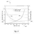
- FIG. 6 is a chart illustrating airflow pressure drop and sound pressure level as a function of door panel-to-cabinet gap, in accordance with an embodiment of the invention.
- FIG. 7 is an isometric view illustrating a computer cabinet having a cooling air intake system configured in accordance with another embodiment of the invention.
- the following disclosure describes several embodiments of airflow intake systems for use with computer cabinet air conditioning systems.
- Some of the airflow intake systems described herein include offset doors or panels that create efficient inlet paths while reducing ambient noise caused by fans or other internal air movers.
- Specific details of several embodiments of the invention are described below with reference to FIGS. 2A-7 to provide a thorough understanding of the embodiments.
- Other details describing well-known structures and systems often associated with computer cabinets and associated air conditioning systems, however, are not set forth below to avoid unnecessarily obscuring the description of the various embodiments. Accordingly, those of ordinary skill in the art will understand that the invention may have other embodiments in addition to those described below. Such embodiments may include other elements and features in addition to those described below, or they may lack one or more of the features or elements described below.
- FIGS. 2A and 2B are isometric views of a computer cabinet 210 , such as a computer cabinet for use with a supercomputer system, having an airflow intake system 202 configured in accordance with an embodiment of the invention.
- the computer cabinet 210 can include a plurality of sidewall portions 222 forming an enclosure around a plurality of computer module compartments 218 (identified individually as a first computer module compartment 218 a , a second computer module compartment 218 b , and a third computer module compartment 218 c ) arranged vertically in a chassis 209 .
- Each of the computer module compartments 218 can hold a plurality of computer modules 212 in edgewise, vertical orientation.
- the computer modules 212 are arranged in close proximity to each other but with air gaps or channels therebetween.
- An air handler or air mover 220 (e.g., a fan, axial flow fan, impellor fan, single stage fan, multi-stage fan, etc.) is positioned in a plenum 223 beneath the computer module compartments 218 and behind an access panel 213 .
- the access panel 213 includes an air inlet 214 having a screen, louvers, or other type of perforated surface that allows air to pass into the plenum 223 and then into an intake 221 of the air mover 220 .
- the computer cabinet 210 can include an inlet air heat exchanger 224 positioned between the air mover 220 and the first computer module compartment 218 a .
- the inlet heat exchanger 224 can include a plurality of cooling fins configured to carry working fluid (e.g., a refrigerant, coolant, water, etc.).
- the cooling fins can be spaced apart from each other to create openings through which air can pass. As the air flows upwardly through the openings, the working fluid absorbs heat from the air, thereby cooling the air before it moves to the first module compartment 218 a .
- an intercooler or other heat exchanger could also be positioned between each of the other computer module compartments 218 .
- the inlet heat exchanger 224 and/or one or more of the other intercoolers or heat exchangers can be omitted.
- the inlet heat exchanger 224 (and/or the other intercoolers if used) can be at least generally similar in structure and function to one or more of the heat exchangers described in detail in U.S. patent application Ser. Nos. 10/805,875, 11/958,114, 12/029,124, and 12/060,377; and/or in U.S. Pat. Nos. 7,330,350 and 7,411,785, each of which is incorporated herein in its entirety by reference.
- the computer cabinet 210 can optionally include an overhead heat exchanger 240 for cooling air exiting the third computer module compartment 218 c before it flows into a surrounding room 201 .
- a flow element 267 can optionally be positioned above the third computer module compartment 218 c to distribute the air flowing into the overhead heat exchanger 240 from the cabinet 210 .
- the overhead heat exchanger 240 can include one or more heat exchanging portions 242 (identified individually as a first heat exchanging portion 242 a and a second heat exchanging portion 242 b ).
- Each of the heat exchanging portions 242 include a plurality of spaced-apart heat exchanging elements 243 that circulate coolant, such as a refrigerant, water, etc.
- the overhead heat exchanger 240 , the heat exchanging portions 242 , and/or the flow element 267 can be at least generally similar in structure and function to the corresponding structures described in detail in U.S. patent application Ser. No. 12/253,672, filed concurrently herewith and entitled “AIR CONDITIONING SYSTEMS FOR COMPUTER SYSTEMS AND ASSOCIATED METHODS,” which is incorporated herein in its entirety by reference.
- a panel or cabinet door 250 is movably positioned in front of an opening 216 that provides access to the computer module compartments 218 and the access panel 213 .
- the opening 216 has an outer periphery 255 defined by a door frame 253 .
- the door frame 253 can include a plurality of exterior surface portions 259 a - c defining, or at least partially defining, a peripheral edge portion of the opening 216 .
- the door 250 has an outer periphery 257 , and includes a plurality of interior surface portions 261 a - d defining, or at least partially defining, a peripheral edge portion of the door 250 .
- the outer periphery 257 of the door 250 is similar in shape (e.g., rectangular) but larger than the outer periphery 255 of the door opening 216 . More specifically, the door panel 250 can have a first width W 1 and a first height H 1 , and as shown in FIG. 2A , the opening 216 can have a second width W 2 that is less than the first width W 1 , and a second height H 2 that is less than the first height H 1 . As a result, the outer periphery 257 of the door 250 can encompass the outer periphery 255 of the opening 216 when the door 250 is in the closed position.
- the door panel 250 can have a first width W 1 and a first height H 1
- the opening 216 can have a second width W 2 that is less than or equal to the first width W 1 , and a second height H 2 that is less than or equal to the first height H 1
- the outer periphery 257 of the door 250 can at least partially extend beyond or encompass the outer periphery 255 of the opening 216 when the door 250 is in the closed position.
- the door 250 and/or the opening 216 can have other shapes, such as round, oval, elliptical, square, octagonal, parallelogram, trapezoidal, etc., and/or other relative sizes without departing from the present disclosure.
- the cabinet door 250 is pivotally attached to the door frame 253 by a plurality of hinges 252 (identified individually as a first hinge 252 a and a second hinge 252 b ) positioned at upper and lower corner portions of the door 250 , respectively.
- the door 250 can also include one or more spacers 251 (identified individually as a first spacer 251 a and a second spacer 251 b ) positioned at upper and lower corner portions of the door 250 , respectively, opposite the hinges 252 .
- a first latch part 254 mounted to the door panel 250 releasably engages a second latch part 256 on the door frame 253 to hold the door in the closed position shown in FIG. 2B .
- the spacers 251 and hinges 252 are shaped and sized or otherwise configured so that the door 250 is positioned in front of the opening 216 , and offset from the exterior surface portions 259 of the door frame 253 a distance D when the door is in the closed position.
- the offset distance D defines a peripheral gap 248 extending between the door 250 and the door frame 253 around, or at least partially around, the outer periphery 257 of the door 250 .
- the offset dimension D can be from about 0.2 inch to about 2 inches, e.g., from about 0.4 inch to about 1.5 inches.
- the offset dimension D can be from about 0.6 inch to about 1.2 inches, or from about 0.7 inch to about 1 inch, or about 0.8 inch. In other embodiments, the offset dimension D can have other dimensions. In still further embodiments, the offset dimension D can vary around the outer periphery 257 of the door 250 without departing from the present disclosure. For example, in some embodiments the door 250 could be canted or angled to vary the offset dimension D around the outer periphery 257 of the door 250 . In yet other embodiments, the door 250 can be offset from the opening 216 and/or the exterior surface portions 259 of the door frame 253 by other means.
- the offset can be achieved by using only extended hinges on one side of the door 250 without the use of spacers on the other side of the door 250 . Accordingly, the present disclosure is not limited to the particular methods and systems illustrated in the accompanying Figures for achieving a desired door gap, but extends to other suitable methods and systems for achieving such a gap.
- FIG. 3 is a cross-sectional, side elevation view of the computer cabinet 210 illustrating aspects of the air mover 220 in more detail.
- the air mover 220 is an axial flow fan (e.g., an electric motor-driven axial flow fan) having a plurality of fan blades 322 that rotate about a central axis 321 .
- the air mover 220 further includes a plurality of stationary vanes or stators 324 positioned upstream of the fan blades 322 to align the flow of pressurized air exiting the air mover 220 .
- a shroud 326 is positioned around the fan blades 322 .
- air (represented by arrows 260 ) flows into the cabinet 210 through the peripheral gap 248 between the door panel 250 and the adjacent portions of the cabinet 210 .
- the peripheral gap 248 extends between the interior surface portions 261 of the door 250 and the adjacent exterior surface portions 259 of the door frame 253 .
- the air (represented by arrows 262 ) flows through the access panel inlet 214 , into the air mover plenum 223 , and then into the air mover 220 via the intake 221 .
- Pressurized air (represented by arrows 264 ) then flows out of the air mover 220 , through the inlet air heat exchanger 224 , and upwardly through the computer module compartments 218 to absorb heat generated by the electronic devices mounted on the computer modules 212 (the computer modules 212 have been removed from FIG. 2B for purposes of clarity).
- the air (represented by arrows 266 ) exits the third computer module compartment 218 c and flows into the overhead heat exchanger 240 via the flow element 267 .
- the air (represented by arrows 268 ) exits the overhead heat exchanger 240 and flows into the room 201 through the heat exchanging portions 242 .
- One advantage of the embodiment of the computer cabinet 210 described above with reference to FIGS. 2A-3 is that the cross-sectional area of the peripheral gap 248 around the door 250 is relatively large. This feature allows cooling air to flow into the computer cabinet 210 through the peripheral gap 248 with relatively low pressure losses, as compared to, for example, prior art systems that utilize sound-absorbing louvers or baffles on cooling air inlets.
- a further advantage of this configuration is that the door panel 250 can be positioned in the direct path of sound waves traveling outward from the air mover 220 . Without wishing to be bound by theory, blocking the sound path with the offset door panel 250 in this manner can provide beneficial acoustic attenuation and noise reduction, while still providing relatively low pressure losses for incoming air.
- FIG. 4 is an enlarged isometric view of an upper portion of the computer cabinet 210 illustrating various aspects of the offset door 250 in more detail.
- the door 250 is offset from the computer cabinet 210 (or more specifically, in this embodiment, from the door frame 253 ) the distance D in a first direction 410 .
- the first direction 410 is perpendicular to, or at least approximately perpendicular to, the door opening 216 .
- the peripheral gap 248 between the exterior surface portions 259 of the door frame 253 and the opposing interior surface portions 261 of the door 250 forms an airflow passageway that extends in a second direction 412 .
- the second direction 412 is parallel to, or at least approximately parallel to, the door opening 216 .
- the second direction 412 is perpendicular to, or at least approximately perpendicular to, the first direction 410 .
- orienting the airflow passageway in the second direction 412 causes operating noise from the air mover 220 ( FIG. 3 ) to be deflected off the door panel 250 and make a right angle turn, or at least approximately a right angle turn, before exiting the computer cabinet 210 .
- This indirect path can significantly reduce the ambient noise resulting from operation of the air mover 220 .
- FIG. 5 is a rear isometric view of the door 250 configured in accordance with an embodiment of the invention.
- the door 250 can include a layer of sound absorbing material 570 attached to a door panel 552 .
- the door panel 552 can be manufactured from metallic material, such as aluminum, steel, etc.; composites; plastics; and/or other suitable structural materials known in the art.
- the door panel 552 is curved such that it has a convex shape facing inwardly toward the computer cabinet 210 .
- sound emitting from the cabinet 210 during operation of the air mover 220 hits the convex surface of the door 250 and is reflected back toward the cabinet 210 . This can prevent or reduce noise scattering, and can reduce noise escaping from the peripheral gap 248 around the door 250 and into the surrounding room.
- the door 250 can be flat and/or have other shapes without departing from the present disclosure.
- the sound absorbing material 570 covers, or at least approximately covers, the interior surface of the door panel 552 (i.e., the surface that faces the door opening 216 ( FIG. 2 )).
- the sound absorbing material 570 or other sound insulating materials, can be attached to the exterior surface of the door panel 552 in addition to, or in place of, the sound absorbing material on the interior surface.
- the sound absorbing material 570 can be attached to the door panel 552 with a suitable adhesive 572 .
- the sound absorbing material 570 can be attached to the door panel 552 with fasteners and/or other suitable materials and methods known in the art.
- the sound absorbing material 570 can include a foam, such as a PVC open cell foam.
- the sound absorbing material 570 can include a filled, lead-free PVC open or closed cell foam referred to as SoundMat PB, provided by the Soundcoat Company of 1 Burt Drive, Deer Park, N.Y., 11729.
- SoundMat PB filled, lead-free PVC open or closed cell foam
- other types of sound absorbing materials can be attached to the door panel 552 .
- the sound absorbing material 570 can be omitted from the door 250 , or the door materials can be selected and/or constructed to provide sufficient sound absorption.
- FIG. 6 illustrates a chart 600 showing representative effects of door gap distance D ( FIGS. 2A-4 ) on intake air pressure drop and sound pressure attenuation for a particular cabinet configuration. More specifically, air pressure drop across the peripheral gap 248 is measured along a first vertical axis 604 a , and sound pressure from the air mover 220 is measured along a second vertical axis 604 b . Door offset distance D is measured along a horizontal axis 602 . As a first plot 606 illustrates, the drop in air pressure across the peripheral gap 248 favorably declines as the door offset distance D increases. As a second plot 608 illustrates, however, increasing the door offset distance D also has the negative effect of increasing the ambient sound pressure from the air mover 220 .
- selecting an offset distance D where the first plot 606 and the second plot 608 cross, or selecting an offset distance D at least proximate to this point can provide a suitable design solution whereby the air pressure drop is relatively low and the sound pressure attenuation is relatively high.
- other door offset distances can be used.
- FIG. 7 is an isometric view of a computer cabinet 710 having an airflow intake system 702 configured in accordance with another embodiment of the invention.
- the computer cabinet 710 can include a plurality of computer module compartments 718 a - c vertically arranged above an air mover 720 .
- the computer cabinet 710 includes a door 750 that is closed against the computer cabinet 710 in a conventional manner (e.g., there is little or no gap around the door).
- the door 750 does not include an air inlet for the air mover 720 .
- the computer cabinet 710 includes a first opening 716 a in a first sidewall 722 a , and a second opening 716 b in an opposite second sidewall 722 b .
- a first panel 770 a is offset from the first sidewall 722 a by a distance Da
- a second panel 770 b is offset from the second sidewall 722 b by a distance Db.
- Each of the panels 770 can include sound absorbing material 772 positioned in front of the corresponding opening 716 .
- air is drawn into the computer cabinet 710 through a first peripheral gap 748 a extending between the first panel 770 a and the first sidewall 722 a , and through a second peripheral gap 748 b extending between the second panel 770 b and the second sidewall 722 b .
- the airflow passageways created by the peripheral gaps 748 can provide relatively low air pressure drops for incoming air, while providing relatively high absorption of sound pressure from the air mover 720 .
Abstract
Description
Claims (20)
Priority Applications (1)
| Application Number | Priority Date | Filing Date | Title |
|---|---|---|---|
| US12/253,692 US7903403B2 (en) | 2008-10-17 | 2008-10-17 | Airflow intake systems and associated methods for use with computer cabinets |
Applications Claiming Priority (1)
| Application Number | Priority Date | Filing Date | Title |
|---|---|---|---|
| US12/253,692 US7903403B2 (en) | 2008-10-17 | 2008-10-17 | Airflow intake systems and associated methods for use with computer cabinets |
Publications (2)
| Publication Number | Publication Date |
|---|---|
| US20100097752A1 US20100097752A1 (en) | 2010-04-22 |
| US7903403B2 true US7903403B2 (en) | 2011-03-08 |
Family
ID=42108486
Family Applications (1)
| Application Number | Title | Priority Date | Filing Date |
|---|---|---|---|
| US12/253,692 Expired - Fee Related US7903403B2 (en) | 2008-10-17 | 2008-10-17 | Airflow intake systems and associated methods for use with computer cabinets |
Country Status (1)
| Country | Link |
|---|---|
| US (1) | US7903403B2 (en) |
Cited By (22)
| Publication number | Priority date | Publication date | Assignee | Title |
|---|---|---|---|---|
| US20090201644A1 (en) * | 2008-02-11 | 2009-08-13 | Kelley Douglas P | Systems and associated methods for cooling computer components |
| US20100326627A1 (en) * | 2009-06-30 | 2010-12-30 | Schon Steven G | Microelectronics cooling system |
| US20110122581A1 (en) * | 2009-11-20 | 2011-05-26 | Lee-Long Chen | Heat exchange device and closed-type electronic apparatus using the same |
| US20120014154A1 (en) * | 2010-07-16 | 2012-01-19 | Rockwell Automation Technologies, Inc. | Motor drive cooling duct system and method |
| US20120014062A1 (en) * | 2010-07-16 | 2012-01-19 | Rockwell Automation Technologies, Inc. | Cooling duct attachment and sealing for a motor drive |
| US20120309284A1 (en) * | 2009-12-22 | 2012-12-06 | Atrium Data | Method and device for reducing the energy consumption of a center comprising energy-intensive apparatuses |
| US8335081B2 (en) | 2010-07-16 | 2012-12-18 | Rockwell Automation Technologies, Inc. | Heat sink cooling arrangement for multiple power electronic circuits |
| US20120329378A1 (en) * | 2006-04-27 | 2012-12-27 | Eaton Corporation | Assembly for Extracting Heat from a Housing for Electronic Equipment |
| US20130229771A1 (en) * | 2012-03-01 | 2013-09-05 | International Business Machines Corporation | Modifying The Spatial Orientation Of A Thermal Acoustic Panel Of A Computing Enclosure Rack |
| US8537539B2 (en) | 2008-10-17 | 2013-09-17 | Cray Inc. | Air conditioning systems for computer systems and associated methods |
| US20130267160A1 (en) * | 2012-04-09 | 2013-10-10 | Chun Long Technology Co., Ltd. | Air distribution structure of industrial cabinet |
| US20140213169A1 (en) * | 2013-01-28 | 2014-07-31 | Ch2M Hill, Inc. | Modular pod |
| US8879270B2 (en) | 2011-05-19 | 2014-11-04 | Pegatron Corporation | Rack mountable server apparatus |
| US20150077935A1 (en) * | 2013-09-13 | 2015-03-19 | Anue Systems, Inc. | Air Filter And Cable Management Assemblies For Network Communication Systems |
| US9185828B2 (en) | 2011-11-17 | 2015-11-10 | Cray Inc. | Rack mounted electronics having connectors with heat cooling fingers |
| US9288935B2 (en) | 2007-12-17 | 2016-03-15 | Cray Inc. | Cooling systems and heat exchangers for cooling computer components |
| US20160100504A1 (en) * | 2014-10-01 | 2016-04-07 | Fujitsu Limited | Cooling device for heating-generating devices |
| US9310856B2 (en) | 2010-04-20 | 2016-04-12 | Cray Inc. | Computer cabinets having progressive air velocity cooling systems and associated methods of manufacture and use |
| US9408330B2 (en) | 2012-04-18 | 2016-08-02 | International Business Machines Coporation | Apparatus to cool a computing device |
| US20180098135A1 (en) * | 2015-04-15 | 2018-04-05 | Coriant Oy | A device-frame for telecommunication devices |
| US10631432B2 (en) * | 2018-03-05 | 2020-04-21 | Seagate Technology Llc | Dynamic air intake control assembly |
| US10952353B1 (en) * | 2019-08-21 | 2021-03-16 | Schneider Electric It Corporation | Thermal buffering module for equipment rack |
Families Citing this family (9)
| Publication number | Priority date | Publication date | Assignee | Title |
|---|---|---|---|---|
| US9759446B2 (en) | 2010-03-26 | 2017-09-12 | Trane International Inc. | Air handling unit with integral inner wall features |
| US10139115B2 (en) * | 2010-03-26 | 2018-11-27 | Trane International Inc. | Air handling unit with inner wall space |
| CN103037665B (en) * | 2011-09-29 | 2015-09-09 | 华为技术有限公司 | A kind of electronic device cooling system with radiator cooler |
| US20140077672A1 (en) | 2012-09-19 | 2014-03-20 | II Grayling A. Love | Data center rack door |
| US9038831B2 (en) * | 2012-11-27 | 2015-05-26 | Oracle International Corporation | Disaster resistant system for maintaining operation of computing devices mounted within storage racks during water and other related contaminating events |
| CN203691803U (en) * | 2013-12-27 | 2014-07-02 | 中兴通讯股份有限公司 | Plug-in box and terminal |
| CN105636379B (en) * | 2014-11-27 | 2018-10-30 | 英业达科技有限公司 | Rotatable door apparatus and the electronic device of keeping out the wind |
| TW202232163A (en) | 2020-09-18 | 2022-08-16 | 美商紐比斯通訊股份有限公司 | Data processing systems and apparatuses including optical communication modules and methods thereof |
| US20220264759A1 (en) * | 2020-11-20 | 2022-08-18 | Nubis Communications, Inc. | Thermal design for rack mount systems including optical communication modules |
Citations (235)
| Publication number | Priority date | Publication date | Assignee | Title |
|---|---|---|---|---|
| US2628018A (en) | 1950-04-13 | 1953-02-10 | Westinghouse Electric Corp | Air translating apparatus |
| US2673721A (en) | 1951-04-13 | 1954-03-30 | Bell Telephone Labor Inc | Apparatus for cooling electron discharge devices |
| US2861782A (en) | 1957-01-18 | 1958-11-25 | Swartz Elmer | Holder for electron tubes |
| US3120166A (en) | 1961-11-16 | 1964-02-04 | Kooltronic Fan Company | Cooling duct for cabinets |
| US3192306A (en) | 1962-09-26 | 1965-06-29 | Philco Corp | Cooling wall structure for electronic equipment cabinet |
| US3236296A (en) | 1961-06-21 | 1966-02-22 | Lambda Electronics Corp | Heat exchanger |
| US3317798A (en) | 1966-04-13 | 1967-05-02 | Ibm | Cooling electrical apparatus |
| US3348609A (en) | 1966-04-29 | 1967-10-24 | Lambda Electronics Corp | Multi-positional power supply module and heat exchange techniques |
| US3525385A (en) | 1968-10-07 | 1970-08-25 | Ralph C Liebert | Computer refrigeration system |
| US3559728A (en) | 1968-11-29 | 1971-02-02 | Kooltronic Fan Co | Electronic equipment rack temperature control |
| US3648754A (en) | 1969-07-28 | 1972-03-14 | Hugo H Sephton | Vortex flow process and apparatus for enhancing interfacial surface and heat and mass transfer |
| US3903404A (en) | 1973-10-17 | 1975-09-02 | Amdahl Corp | Computer construction and method |
| US3942426A (en) | 1975-04-14 | 1976-03-09 | Restaurant Technology, Inc. | Heated sanitary sandwich bin with air curtains |
| US4016357A (en) | 1975-07-18 | 1977-04-05 | Burroughs Corporation | Floor structure for the environment of a modular computer system |
| US4158875A (en) | 1977-05-24 | 1979-06-19 | Nippon Electric Co., Ltd. | Air cooling equipment for electronic systems |
| US4261519A (en) | 1978-12-20 | 1981-04-14 | Honeywell Information Systems Inc. | Air distribution system |
| US4270362A (en) | 1977-04-29 | 1981-06-02 | Liebert Corporation | Control system for an air conditioning system having supplementary, ambient derived cooling |
| US4271678A (en) | 1977-03-21 | 1981-06-09 | Liebert Corporation | Liquid refrigeration system for an enclosure temperature controlled outdoor cooling or pre-conditioning |
| US4306613A (en) | 1980-03-10 | 1981-12-22 | Christopher Nicholas S | Passive cooling system |
| US4313310A (en) | 1979-09-07 | 1982-02-02 | Fujitsu Limited | Cooling system |
| US4315300A (en) | 1979-01-29 | 1982-02-09 | The United States Of America As Represented By The Secretary Of The Navy | Cooling arrangement for plug-in module assembly |
| US4386651A (en) | 1980-12-02 | 1983-06-07 | Autz + Herrmann Metallwaren-Und Maschinenfabrik | Heat exchanger accessory for electronic circuit cabinets |
| US4449579A (en) | 1981-01-30 | 1984-05-22 | Tokyo Shibaura Denki Kabushiki Kaisha | Cooling apparatus for a closed housing |
| US4458296A (en) | 1982-05-19 | 1984-07-03 | The Boeing Company | Avionic shelf assembly |
| US4473382A (en) | 1983-07-08 | 1984-09-25 | Lasko Metal Products, Inc. | Air cleaning and circulating apparatus |
| US4513351A (en) | 1982-09-29 | 1985-04-23 | International Business Machines Corporation | Electronic assembly with forced convection cooling |
| US4528614A (en) | 1983-10-07 | 1985-07-09 | Westinghouse Electric Corp. | Electric control center having integral air-ventilation system |
| US4535386A (en) | 1983-05-23 | 1985-08-13 | Allen-Bradley Company | Natural convection cooling system for electronic components |
| US4642715A (en) | 1984-11-01 | 1987-02-10 | Miltope Corporation | Environmental conditioning and safety system for disk-type mass memories |
| US4644443A (en) | 1985-09-27 | 1987-02-17 | Texas Instruments Incorporated | Computer cooling system using recycled coolant |
| US4691274A (en) | 1986-04-29 | 1987-09-01 | Modular Power Corporation | Modular electronic power supply |
| US4702154A (en) | 1987-01-28 | 1987-10-27 | Dodson Douglas A | Cooling system for personal computer |
| US4728160A (en) * | 1986-10-22 | 1988-03-01 | Digital Equipment Corporation | Cabinet for a computer assembly |
| US4767262A (en) | 1987-04-16 | 1988-08-30 | Knurr-Mechanik Fur Die Elektronik Aktiengesellschaft | Fan slide-in unit |
| US4774631A (en) | 1984-11-15 | 1988-09-27 | Fujitsu Limited | Cooling structure of electronic equipment rack |
| US4797783A (en) | 1984-09-26 | 1989-01-10 | Nec Corporation | Air cooling equipment for electronic systems |
| US4798238A (en) | 1981-05-27 | 1989-01-17 | D.S.D.P. - S.P.A | Shelter for thermally conditioning electronic appliances |
| US4860163A (en) | 1988-08-05 | 1989-08-22 | American Telephone And Telegraph Company | Communication equipment cabinet cooling arrangement |
| US4874127A (en) | 1987-11-12 | 1989-10-17 | Collier William R | Climate control apparatus |
| US4901200A (en) | 1987-10-14 | 1990-02-13 | Schroff Gmbh | Insertable housing |
| US4911231A (en) | 1987-10-15 | 1990-03-27 | Bicc Public Limited Company | Electronic enclosure cooling system |
| US4993482A (en) | 1990-01-09 | 1991-02-19 | Microelectronics And Computer Technology Corporation | Coiled spring heat transfer element |
| US5000079A (en) | 1990-05-17 | 1991-03-19 | Mardis Michael C | Noise-attenuating ventilation pedestal for an electronic enclosure |
| US5019880A (en) | 1988-01-07 | 1991-05-28 | Prime Computer, Inc. | Heat sink apparatus |
| US5035628A (en) | 1990-05-29 | 1991-07-30 | Amp Incorporated | Electrical connector for electrically interconnecting two parallel surfaces |
| US5060716A (en) | 1989-03-31 | 1991-10-29 | Heine William F | Heat dissipating device and combination including same |
| US5090476A (en) | 1990-03-20 | 1992-02-25 | Rittal-Werk Rudolf Loh Gmbh & Co. Kg | Air-water heat exchanger for a control box |
| US5101320A (en) | 1991-01-22 | 1992-03-31 | Hayes Microcomputer Products, Inc. | Apparatus for rack mounting multiple circuit boards |
| US5131233A (en) | 1991-03-08 | 1992-07-21 | Cray Computer Corporation | Gas-liquid forced turbulence cooling |
| US5150277A (en) | 1990-05-04 | 1992-09-22 | At&T Bell Laboratories | Cooling of electronic equipment cabinets |
| US5161087A (en) | 1990-10-15 | 1992-11-03 | International Business Machines Corporation | Pivotal heat sink assembly |
| US5165466A (en) | 1991-12-11 | 1992-11-24 | Morteza Arbabian | Modular heat exchanger having delayed heat transfer capability |
| US5196989A (en) | 1990-04-09 | 1993-03-23 | Trw Inc. | Rigid circuit board structure using impingement cooling |
| US5263538A (en) | 1991-10-18 | 1993-11-23 | Aerospatiale Societe Nationale Industrielle | Equipment support, fixing and heat conditioning panel |
| US5273438A (en) | 1992-08-19 | 1993-12-28 | The Whitaker Corporation | Canted coil spring array and method for producing the same |
| US5297990A (en) | 1991-02-01 | 1994-03-29 | Meissner & Wurst Gmbh & Co. | Filter-ventilator-arrangement |
| US5323847A (en) | 1990-08-01 | 1994-06-28 | Hitachi, Ltd. | Electronic apparatus and method of cooling the same |
| US5326317A (en) | 1991-10-18 | 1994-07-05 | Matsushita Seiko Co., Ltd. | Ventilator |
| US5329425A (en) | 1991-02-25 | 1994-07-12 | Alcatel N.V. | Cooling system |
| US5339214A (en) | 1993-02-12 | 1994-08-16 | Intel Corporation | Multiple-fan microprocessor cooling through a finned heat pipe |
| US5345779A (en) | 1993-04-23 | 1994-09-13 | Liebert Corporation | Modular floor sub-structure for the operational support of computer systems |
| US5365402A (en) | 1990-11-30 | 1994-11-15 | Hitachi, Ltd. | Cooling apparatus of electronic device |
| US5376008A (en) | 1993-10-21 | 1994-12-27 | The Whitaker Corporation | Retainer for elastomeric contact element |
| US5395251A (en) | 1993-10-21 | 1995-03-07 | The Whitaker Corporation | Board retainer system for active electrical connector assembly |
| US5402313A (en) | 1993-05-21 | 1995-03-28 | Cummins Engine Company, Inc. | Electronic component heat sink attachment using a canted coil spring |
| US5410448A (en) | 1992-03-02 | 1995-04-25 | Digital Equipment Corporation | Adaptive cooling system |
| US5414591A (en) * | 1991-04-15 | 1995-05-09 | Hitachi, Ltd. | Magnetic disk storage system |
| US5467250A (en) | 1994-03-21 | 1995-11-14 | Hubbell Incorporated | Electrical cabinet with door-mounted heat exchanger |
| US5467609A (en) | 1993-04-23 | 1995-11-21 | Liebert Corporation | Modular floor sub-structure for the operational support of computer systems |
| US5471850A (en) | 1993-07-09 | 1995-12-05 | Acurex Corporation | Refrigeration system and method for very large scale integrated circuits |
| US5491310A (en) | 1990-08-16 | 1996-02-13 | Jen; Wang H. | Acoustic board |
| US5493474A (en) | 1995-02-14 | 1996-02-20 | Hewlett-Packard Company | Enclosure with redundant air moving system |
| US5547272A (en) * | 1995-04-24 | 1996-08-20 | At&T Global Information Solutions Company | Modular cabinet bezel |
| US5572403A (en) | 1995-01-18 | 1996-11-05 | Dell Usa, L.P. | Plenum bypass serial fan cooling subsystem for computer systems |
| US5603375A (en) | 1991-02-01 | 1997-02-18 | Commonwealth Scientific And Industrial Research Organisation | Heat transfer device |
| US5684671A (en) * | 1995-08-22 | 1997-11-04 | Sequent Computer Systems, Inc. | Packaging architecture for a data server |
| US5685363A (en) | 1994-12-08 | 1997-11-11 | Nissin Electric Co., Ltd. | Substrate holding device and manufacturing method therefor |
| US5707205A (en) | 1996-07-04 | 1998-01-13 | Matsushita Electric Industrial Co., Ltd. | Fan device |
| US5709100A (en) | 1996-08-29 | 1998-01-20 | Liebert Corporation | Air conditioning for communications stations |
| US5718628A (en) | 1995-05-02 | 1998-02-17 | Nit Power And Building Facilities, Inc. | Air conditioning method in machine room having forced air-cooling equipment housed therein |
| US5749702A (en) | 1996-10-15 | 1998-05-12 | Air Handling Engineering Ltd. | Fan for air handling system |
| US5782546A (en) | 1996-04-10 | 1998-07-21 | Nec Corporation | Door structure for cabinets |
| US5793610A (en) | 1996-01-25 | 1998-08-11 | Dell Usa, L.P. | Multi-position air regulation device |
| US5829676A (en) | 1996-11-11 | 1998-11-03 | Kabushiki Kaisha Toyoda Jidoshokki Seisakusho | Heating apparatus and method for vehicle |
| US5880931A (en) | 1998-03-20 | 1999-03-09 | Tilton; Donald E. | Spray cooled circuit card cage |
| US5927386A (en) | 1998-08-24 | 1999-07-27 | Macase Industrial Group Ga., Inc. | Computer hard drive heat sink assembly |
| US5979541A (en) | 1995-11-20 | 1999-11-09 | Seiko Epson Corporation | Cooling fan and cooling fan assembly |
| US6021047A (en) * | 1997-10-24 | 2000-02-01 | Dell U.S.A., L,P. | Computer and a rack mount system and method for a computer |
| US6026565A (en) | 1997-06-12 | 2000-02-22 | Harris Corporation | Housing for diverse cooling configuration printed circuit cards |
| US6034870A (en) | 1999-01-27 | 2000-03-07 | Sun Microsystems, Inc. | Computer system having a highly efficient forced air cooling subsystem |
| US6039414A (en) * | 1998-12-11 | 2000-03-21 | Alcatel Usa Sourcing, L.P. | Modular electronic enclosure having rotational molded plastic interlocking components |
| US6046908A (en) | 1998-09-04 | 2000-04-04 | Long Well Electronics Corp. | Heat-radiating structure of power adapter |
| US6052278A (en) * | 1998-11-13 | 2000-04-18 | Hewlett-Packard Company | Data storage module and enclosure system |
| US6104608A (en) * | 1997-10-30 | 2000-08-15 | Emc Corporation | Noise reduction hood for an electronic system enclosure |
| US6115242A (en) | 1997-10-24 | 2000-09-05 | Advanced Micro Devices, Inc. | Chip chassis including a micro-backplane for receiving and connecting a plurality of computer chips |
| US6132171A (en) | 1997-06-10 | 2000-10-17 | Matsushita Electric Industrial Co., Ltd. | Blower and method for molding housing thereof |
| US6135875A (en) | 1999-06-29 | 2000-10-24 | Emc Corporation | Electrical cabinet |
| US6158502A (en) | 1996-11-18 | 2000-12-12 | Novel Concepts, Inc. | Thin planar heat spreader |
| US6164369A (en) | 1999-07-13 | 2000-12-26 | Lucent Technologies Inc. | Door mounted heat exchanger for outdoor equipment enclosure |
| US6185098B1 (en) | 2000-01-31 | 2001-02-06 | Chatsworth Products, Inc. | Co-location server cabinet |
| US6183196B1 (en) | 1998-05-14 | 2001-02-06 | Matsushita Electric Industrial Co., Ltd. | Blower |
| US6182787B1 (en) | 1999-01-12 | 2001-02-06 | General Electric Company | Rigid sandwich panel acoustic treatment |
| US6205796B1 (en) | 1999-03-29 | 2001-03-27 | International Business Machines Corporation | Sub-dew point cooling of electronic systems |
| US6208510B1 (en) | 1999-07-23 | 2001-03-27 | Teradyne, Inc. | Integrated test cell cooling system |
| US6236564B1 (en) | 2000-04-13 | 2001-05-22 | Enlight Corporation | Detachable fan rack mounting structure |
| US6272012B1 (en) | 2000-02-03 | 2001-08-07 | Crystal Group Inc. | System and method for cooling compact PCI circuit cards in a computer |
| US6305180B1 (en) | 1999-09-13 | 2001-10-23 | British Broadcasting Corporation | Cooling system for use in cooling electronic equipment |
| US6310773B1 (en) | 1999-12-21 | 2001-10-30 | Intel Corporation | Heat sink system |
| US20010052412A1 (en) | 1999-08-20 | 2001-12-20 | Harri Tikka | Cooling system for a cabinet |
| US6332946B1 (en) | 1998-03-12 | 2001-12-25 | International Business Machines Corporation | Method for assembling a multi-layered ceramic package |
| US6351381B1 (en) | 2001-06-20 | 2002-02-26 | Thermal Corp. | Heat management system |
| US6359779B1 (en) | 1999-04-05 | 2002-03-19 | Western Digital Ventures, Inc. | Integrated computer module with airflow accelerator |
| US6361892B1 (en) | 1999-12-06 | 2002-03-26 | Technology Management, Inc. | Electrochemical apparatus with reactant micro-channels |
| US20020041484A1 (en) * | 1999-06-28 | 2002-04-11 | Sun Microsystems, Inc. | Computer system housing configuration |
| US6396684B2 (en) * | 1998-04-10 | 2002-05-28 | Lg Electronics Inc. | Structure of tower-type personal computer |
| US20020072809A1 (en) | 2000-10-24 | 2002-06-13 | Michael Zuraw | Microcomputer control of physical devices |
| US6416330B1 (en) | 2000-07-17 | 2002-07-09 | Cray Inc. | Canted coil spring conductor electrical circuit connector |
| US6435266B1 (en) | 2001-05-01 | 2002-08-20 | Aavid Taiwan Inc. | Heat-pipe type radiator and method for producing the same |
| US6439340B1 (en) | 2000-11-17 | 2002-08-27 | Astech Manufacturing, Inc. | Acoustically treated structurally reinforced sound absorbing panel |
| US6462944B1 (en) | 2000-10-25 | 2002-10-08 | Macase Industrial Group Ga., Inc. | Computer cabinet cooling system |
| US6481527B1 (en) | 2001-03-14 | 2002-11-19 | Emc Corporation | Methods and apparatus for attenuating noise from a cabinet that houses computer equipment |
| US20020172007A1 (en) | 2001-05-16 | 2002-11-21 | Pautsch Gregory W. | Spray evaporative cooling system and method |
| US20020181200A1 (en) | 2001-05-29 | 2002-12-05 | Je-Young Chang | Computer assembly providing cooling for more than one electronic component |
| US6501652B2 (en) | 1997-02-24 | 2002-12-31 | Fujitsu Limited | Heat sink and information processor using it |
| US20030010477A1 (en) | 2001-07-10 | 2003-01-16 | Dmitry Khrustalev | Thermal bus for cabinets housing high power electronics equipment |
| US6515862B1 (en) | 2000-03-31 | 2003-02-04 | Intel Corporation | Heat sink assembly for an integrated circuit |
| US20030033135A1 (en) | 2000-04-03 | 2003-02-13 | Xerox Corporation | Method and apparatus for extracting infinite ambiguity when factoring finite state transducers |
| US6519955B2 (en) | 2000-04-04 | 2003-02-18 | Thermal Form & Function | Pumped liquid cooling system using a phase change refrigerant |
| US6524064B2 (en) | 2001-05-23 | 2003-02-25 | Industrial Technology Research Institute | Fan filter unit with sound-absorbing wedges |
| US20030053293A1 (en) * | 2001-09-14 | 2003-03-20 | Beitelmal Abdlmonem H. | Method and apparatus for individually cooling components of electronic systems |
| US20030056941A1 (en) | 2001-09-27 | 2003-03-27 | Chih-Hsi Lai | Double heat exchange module for a portable computer |
| US6546998B2 (en) | 2000-12-01 | 2003-04-15 | Lg Electronics Inc. | Tube structure of micro-multi channel heat exchanger |
| US6550530B1 (en) | 2002-04-19 | 2003-04-22 | Thermal Corp. | Two phase vacuum pumped loop |
| US6554697B1 (en) | 1998-12-30 | 2003-04-29 | Engineering Equipment And Services, Inc. | Computer cabinet design |
| US6557624B1 (en) | 2000-08-09 | 2003-05-06 | Liebert Corporation | Configurable system and method for cooling a room |
| US6557357B2 (en) | 2000-02-18 | 2003-05-06 | Toc Technology, Llc | Computer rack heat extraction device |
| US6564571B2 (en) | 2000-07-17 | 2003-05-20 | Liebert Corporation | High availability energy |
| US6564858B1 (en) | 2000-07-17 | 2003-05-20 | Liebert Corporation | Overhead cooling system with selectively positioned paths of airflow |
| US6582192B2 (en) | 2001-07-27 | 2003-06-24 | Shou-Tang Tseng | Omnidirectional electric fan |
| US6587340B2 (en) | 2001-04-10 | 2003-07-01 | Sun Microsystems, Inc. | Maintaining cooling efficiency during air mover failure |
| US6609592B2 (en) | 2000-06-30 | 2003-08-26 | Short Brothers Plc | Noise attenuation panel |
| US20030161102A1 (en) | 2002-03-08 | 2003-08-28 | Harrison Lee | Cooler of notebook personal computer and fabrication method thereof |
| US6628520B2 (en) * | 2002-02-06 | 2003-09-30 | Hewlett-Packard Development Company, L.P. | Method, apparatus, and system for cooling electronic components |
| US20030183446A1 (en) | 2002-03-26 | 2003-10-02 | Ford Motor Company | Fan shroud with built in noise reduction |
| US6631078B2 (en) | 2002-01-10 | 2003-10-07 | International Business Machines Corporation | Electronic package with thermally conductive standoff |
| US6644384B2 (en) | 2001-09-21 | 2003-11-11 | Liebert Corporation | Modular low profile cooling system |
| US6661660B2 (en) | 2000-12-22 | 2003-12-09 | Intel Corporation | Integrated vapor chamber heat sink and spreader and an embedded direct heat pipe attachment |
| US20040008491A1 (en) | 2002-07-11 | 2004-01-15 | Yung-Shun Chen | Heat dissipation apparatus |
| US6684457B2 (en) | 2000-05-25 | 2004-02-03 | Liebert Corporation | Adjustable and reversible hinge assembly |
| US20040020225A1 (en) | 2002-08-02 | 2004-02-05 | Patel Chandrakant D. | Cooling system |
| US6690576B2 (en) | 2001-07-31 | 2004-02-10 | Hewlett Packard Development Company, L.P. | Externally mounted on-line replaceable fan module |
| JP2004079754A (en) | 2002-08-16 | 2004-03-11 | Fujikura Ltd | Heat sink |
| US6705625B2 (en) | 2000-10-27 | 2004-03-16 | Liebert Corporation | Caster arrangement for use on access floors |
| US20040052052A1 (en) | 2002-09-18 | 2004-03-18 | Rivera Rudy A. | Circuit cooling apparatus |
| US6714412B1 (en) | 2002-09-13 | 2004-03-30 | International Business Machines Corporation | Scalable coolant conditioning unit with integral plate heat exchanger/expansion tank and method of use |
| US6724617B2 (en) | 2000-07-19 | 2004-04-20 | Internet Research Institute, Inc. | Server unit comprising stacked multiple server unit cabinets accommodating multiple cartridge type server units |
| US6742068B2 (en) * | 1997-06-30 | 2004-05-25 | Emc Corporation | Data server with hot replaceable processing unit modules |
| US6745579B2 (en) | 2000-02-18 | 2004-06-08 | Toc Technology, Llc | Computer room air flow method and apparatus |
| US6755280B2 (en) | 2001-03-09 | 2004-06-29 | Airbus France | Method for producing a panel comprising an adapted acoustically resistive layer and panel so obtained |
| US6761212B2 (en) | 2000-05-25 | 2004-07-13 | Liebert Corporation | Spiral copper tube and aluminum fin thermosyphon heat exchanger |
| US6772604B2 (en) | 2002-10-03 | 2004-08-10 | Hewlett-Packard Development Company, L.P. | Cooling of data centers |
| US6775137B2 (en) | 2002-11-25 | 2004-08-10 | International Business Machines Corporation | Method and apparatus for combined air and liquid cooling of stacked electronics components |
| US6776707B2 (en) | 1998-12-30 | 2004-08-17 | Engineering Equipment And Services, Inc. | Computer cabinet |
| US6796372B2 (en) | 2001-06-12 | 2004-09-28 | Liebert Corporation | Single or dual buss thermal transfer system |
| US6819563B1 (en) | 2003-07-02 | 2004-11-16 | International Business Machines Corporation | Method and system for cooling electronics racks using pre-cooled air |
| US20040250990A1 (en) | 2003-06-12 | 2004-12-16 | Phoenix Contact Gmbh & Co. Kg | Cooling element for heat dissipation in electronic components |
| US6836407B2 (en) | 2002-01-04 | 2004-12-28 | Intel Corporation | Computer system having a plurality of server units transferring heat to a fluid flowing through a frame-level fluid-channeling structure |
| US6854659B2 (en) | 2001-09-21 | 2005-02-15 | Kliebert Corporation | Interactive sensors for environmental control |
| US6860713B2 (en) | 2002-11-27 | 2005-03-01 | Nidec Corporation | Fan with collapsible blades, redundant fan system, and related method |
| US6867966B2 (en) | 2002-05-31 | 2005-03-15 | Verari Systems, Inc. | Method and apparatus for rack mounting computer components |
| WO2005027609A1 (en) | 2003-09-10 | 2005-03-24 | Hamman Brian A | Liquid cooling system |
| US6875101B1 (en) * | 2003-11-18 | 2005-04-05 | Robert Chien | Computer housing ventilation arrangement |
| US6882531B2 (en) | 2002-07-23 | 2005-04-19 | Silicon Graphics, Inc. | Method and rack for exchanging air with modular bricks in a computer system |
| US6881898B2 (en) | 2001-03-02 | 2005-04-19 | Liebert Corporation | Remote distribution cabinet |
| US20050120737A1 (en) | 2003-12-05 | 2005-06-09 | Borror Steven A. | Cooling system for high density heat load |
| US6909611B2 (en) | 2002-05-31 | 2005-06-21 | Verari System, Inc. | Rack mountable computer component and method of making same |
| US6914780B1 (en) | 2003-01-16 | 2005-07-05 | Cisco Technology, Inc. | Methods and apparatus for cooling a circuit board component using a heat pipe assembly |
| US20050161205A1 (en) | 2002-08-09 | 2005-07-28 | Ashe Morris Ltd. | Reduced volume heat exchangers |
| US20050162834A1 (en) | 2004-01-23 | 2005-07-28 | Takeshi Nishimura | Electronics connector with heat sink |
| US20050168945A1 (en) | 2003-12-29 | 2005-08-04 | Giovanni Coglitore | Computer rack cooling system with variable airflow impedance |
| US6932443B1 (en) | 2000-10-19 | 2005-08-23 | Multipower, Inc. | Outdoor cabinet for electrical components |
| US20050186070A1 (en) | 2004-02-23 | 2005-08-25 | Ling-Zhong Zeng | Fan assembly and method |
| US20050207116A1 (en) | 2004-03-22 | 2005-09-22 | Yatskov Alexander I | Systems and methods for inter-cooling computer cabinets |
| US20050225936A1 (en) | 2002-03-28 | 2005-10-13 | Tony Day | Cooling of a data centre |
| US20050241810A1 (en) | 2004-04-29 | 2005-11-03 | Hewlett-Packard Development Company, L.P. | Controllable flow resistance in a cooling apparatus |
| US6975510B1 (en) | 2003-05-09 | 2005-12-13 | Linux Networx | Ventilated housing for electronic components |
| US6992889B1 (en) | 2000-01-25 | 2006-01-31 | Fujitsu Limited | Retention module, heat sink and electronic device |
| US6997245B2 (en) | 2002-08-28 | 2006-02-14 | Thermal Corp. | Vapor chamber with sintered grooved wick |
| US6997741B2 (en) | 2003-11-15 | 2006-02-14 | Cray Inc. | Systems and methods for partitioning banks of processors in large computer systems |
| US20060044758A1 (en) | 2004-08-30 | 2006-03-02 | Power-One As | System and method for managing temperature in an interior-portion of a cabinet |
| US20060054380A1 (en) * | 2004-09-14 | 2006-03-16 | Cray Inc. | Acoustic absorbers for use with computer cabinet fans and other cooling systems |
| US7016191B2 (en) * | 2003-11-28 | 2006-03-21 | Hitachi, Ltd. | Disk array device |
| US20060102322A1 (en) | 2004-11-14 | 2006-05-18 | Liebert Corp. | Integrated heat exchangers in a rack for verticle board style computer systems |
| US7051946B2 (en) | 2003-05-29 | 2006-05-30 | Hewlett-Packard Development Company, L.P. | Air re-circulation index |
| US7051802B2 (en) | 2000-03-21 | 2006-05-30 | Liebert Corp. | Method and apparatus for cooling electronic enclosures |
| US7120017B2 (en) | 2004-01-27 | 2006-10-10 | Tong-Wen Shieh | Heat dissipating system of personal computer |
| US7120027B2 (en) | 2004-07-08 | 2006-10-10 | Cray Inc. | Assemblies for mounting electronic devices and associated heat sinks to computer modules and other structures |
| US7123477B2 (en) | 2004-03-31 | 2006-10-17 | Rackable Systems, Inc. | Computer rack cooling system |
| US7144320B2 (en) | 2004-12-29 | 2006-12-05 | Turek James R | Air distribution arrangement for rack-mounted equipment |
| US7154748B2 (en) | 2003-02-20 | 2006-12-26 | Fujitsu Limited | Cooling structure of electronic equipment and information processing equipment using the cooling structure |
| US7152418B2 (en) | 2004-07-06 | 2006-12-26 | Intel Corporation | Method and apparatus to manage airflow in a chassis |
| US20070030650A1 (en) | 2005-08-04 | 2007-02-08 | Liebert Corporation | Electronic equipment cabinet with integrated, high capacity, cooling system, and backup ventiliation |
| US7177156B2 (en) | 2004-07-08 | 2007-02-13 | Cray Inc. | Assemblies for holding heat sinks and other structures in contact with electronic devices and other apparatuses |
| US7182208B2 (en) | 2002-12-20 | 2007-02-27 | Agilent Technologies, Inc. | Instrument rack with direct exhaustion |
| US7187549B2 (en) | 2004-06-30 | 2007-03-06 | Teradyne, Inc. | Heat exchange apparatus with parallel flow |
| US7193851B2 (en) | 2004-12-09 | 2007-03-20 | Cray Inc. | Assemblies for holding heat sinks and other structures in contact with electronic devices and other apparatuses |
| US7193846B1 (en) | 1999-04-26 | 2007-03-20 | Gateway Inc. | CPU fan assembly |
| US7209351B2 (en) | 2004-06-30 | 2007-04-24 | Intel Corporation | Telecom equipment chassis using modular air cooling system |
| US7215552B2 (en) | 2005-03-23 | 2007-05-08 | Intel Corporation | Airflow redistribution device |
| US7218516B2 (en) * | 2004-09-24 | 2007-05-15 | Shuttle, Inc. | Inlet airflow guiding structure for computers |
| US7226353B2 (en) | 2004-01-13 | 2007-06-05 | Power Of 4, Llc | Cabinet for computer devices with air distribution device |
| US7242579B2 (en) | 2004-01-09 | 2007-07-10 | International Business Machines Corporation | System and method for providing cooling in a three-dimensional infrastructure for massively scalable computers |
| US7255640B2 (en) | 2002-10-11 | 2007-08-14 | Liebert Corporation | Cable and air management adapter system for enclosures housing electronic equipment |
| US7259963B2 (en) | 2004-12-29 | 2007-08-21 | American Power Conversion Corp. | Rack height cooling |
| US20070211428A1 (en) | 2006-03-08 | 2007-09-13 | Cray Inc. | Multi-stage air movers for cooling computer systems and for other uses |
| US7286351B2 (en) | 2005-05-06 | 2007-10-23 | International Business Machines Corporation | Apparatus and method for facilitating cooling of an electronics rack employing a closed loop heat exchange system |
| US7304842B2 (en) | 2004-06-14 | 2007-12-04 | Cray Inc. | Apparatuses and methods for cooling electronic devices in computer systems |
| US7315448B1 (en) | 2005-06-01 | 2008-01-01 | Hewlett-Packard Development Company, L.P. | Air-cooled heat generating device airflow control system |
| US20080018212A1 (en) | 2006-07-18 | 2008-01-24 | Liebert Corporation | Integral Swivel Hydraulic Connectors, Door Hinges, and Methods and Systems for Their Use |
| US7330350B2 (en) | 2004-06-04 | 2008-02-12 | Cray Inc. | Systems and methods for cooling computer modules in computer cabinets |
| US20080078202A1 (en) | 2006-09-28 | 2008-04-03 | Chin-Kuang Luo | Heat dissipating system and method |
| US7362571B2 (en) | 2004-09-16 | 2008-04-22 | Cray Inc. | Inlet flow conditioners for computer cabinet air conditioning systems |
| US20080092387A1 (en) | 2006-10-10 | 2008-04-24 | International Business Machines Corporation | Method of assembling a cooling system for a multi-component electronics system |
| US20080098763A1 (en) | 2006-10-30 | 2008-05-01 | Fujitsu Limited | Air-conditioning installation and computer system |
| US7385810B2 (en) | 2005-04-18 | 2008-06-10 | International Business Machines Corporation | Apparatus and method for facilitating cooling of an electronics rack employing a heat exchange assembly mounted to an outlet door cover of the electronics rack |
| US20080158814A1 (en) | 2006-12-27 | 2008-07-03 | Takeshi Hattori | Plug-in unit and electronic apparatus |
| US7397661B2 (en) | 2006-08-25 | 2008-07-08 | International Business Machines Corporation | Cooled electronics system and method employing air-to-liquid heat exchange and bifurcated air flow |
| US7411785B2 (en) | 2006-06-05 | 2008-08-12 | Cray Inc. | Heat-spreading devices for cooling computer systems and associated methods of use |
| US7418825B1 (en) | 2004-11-19 | 2008-09-02 | American Power Conversion Corporation | IT equipment cooling |
| US20080216493A1 (en) | 2007-03-08 | 2008-09-11 | Liebert Corporation | Microchannel cooling condenser for precision cooling applications |
| US7430118B1 (en) | 2007-06-04 | 2008-09-30 | Yahoo! Inc. | Cold row encapsulation for server farm cooling system |
| US7513923B1 (en) | 2005-05-23 | 2009-04-07 | Force10 Networks, Inc. | Variable impedance air filter for electronic systems |
| US7542287B2 (en) | 2005-09-19 | 2009-06-02 | Chatsworth Products, Inc. | Air diverter for directing air upwardly in an equipment enclosure |
| US7554803B2 (en) | 2005-04-13 | 2009-06-30 | Dell Products L.P. | Method and apparatus for cooling an information handling system |
| US7710720B2 (en) | 2007-01-23 | 2010-05-04 | Fujitsu Limited | Electronic device and fire protecting mechanism of the electronic device |
Family Cites Families (2)
| Publication number | Priority date | Publication date | Assignee | Title |
|---|---|---|---|---|
| CA2230173A1 (en) * | 1998-02-23 | 1999-08-23 | Frederick Dimmick | Illuminated modular sign having adjustable quick release modules |
| JP2000331195A (en) * | 1999-05-19 | 2000-11-30 | Nec Corp | Three-dimensional display method and device and recording medium stored with three-dimensional display program |
-
2008
- 2008-10-17 US US12/253,692 patent/US7903403B2/en not_active Expired - Fee Related
Patent Citations (245)
| Publication number | Priority date | Publication date | Assignee | Title |
|---|---|---|---|---|
| US2628018A (en) | 1950-04-13 | 1953-02-10 | Westinghouse Electric Corp | Air translating apparatus |
| US2673721A (en) | 1951-04-13 | 1954-03-30 | Bell Telephone Labor Inc | Apparatus for cooling electron discharge devices |
| US2861782A (en) | 1957-01-18 | 1958-11-25 | Swartz Elmer | Holder for electron tubes |
| US3236296A (en) | 1961-06-21 | 1966-02-22 | Lambda Electronics Corp | Heat exchanger |
| US3120166A (en) | 1961-11-16 | 1964-02-04 | Kooltronic Fan Company | Cooling duct for cabinets |
| US3192306A (en) | 1962-09-26 | 1965-06-29 | Philco Corp | Cooling wall structure for electronic equipment cabinet |
| US3317798A (en) | 1966-04-13 | 1967-05-02 | Ibm | Cooling electrical apparatus |
| US3348609A (en) | 1966-04-29 | 1967-10-24 | Lambda Electronics Corp | Multi-positional power supply module and heat exchange techniques |
| US3525385A (en) | 1968-10-07 | 1970-08-25 | Ralph C Liebert | Computer refrigeration system |
| US3559728A (en) | 1968-11-29 | 1971-02-02 | Kooltronic Fan Co | Electronic equipment rack temperature control |
| US3648754A (en) | 1969-07-28 | 1972-03-14 | Hugo H Sephton | Vortex flow process and apparatus for enhancing interfacial surface and heat and mass transfer |
| US3903404A (en) | 1973-10-17 | 1975-09-02 | Amdahl Corp | Computer construction and method |
| US3942426A (en) | 1975-04-14 | 1976-03-09 | Restaurant Technology, Inc. | Heated sanitary sandwich bin with air curtains |
| US4016357A (en) | 1975-07-18 | 1977-04-05 | Burroughs Corporation | Floor structure for the environment of a modular computer system |
| US4271678A (en) | 1977-03-21 | 1981-06-09 | Liebert Corporation | Liquid refrigeration system for an enclosure temperature controlled outdoor cooling or pre-conditioning |
| US4270362A (en) | 1977-04-29 | 1981-06-02 | Liebert Corporation | Control system for an air conditioning system having supplementary, ambient derived cooling |
| US4158875A (en) | 1977-05-24 | 1979-06-19 | Nippon Electric Co., Ltd. | Air cooling equipment for electronic systems |
| US4261519A (en) | 1978-12-20 | 1981-04-14 | Honeywell Information Systems Inc. | Air distribution system |
| US4315300A (en) | 1979-01-29 | 1982-02-09 | The United States Of America As Represented By The Secretary Of The Navy | Cooling arrangement for plug-in module assembly |
| US4313310A (en) | 1979-09-07 | 1982-02-02 | Fujitsu Limited | Cooling system |
| US4306613A (en) | 1980-03-10 | 1981-12-22 | Christopher Nicholas S | Passive cooling system |
| US4386651A (en) | 1980-12-02 | 1983-06-07 | Autz + Herrmann Metallwaren-Und Maschinenfabrik | Heat exchanger accessory for electronic circuit cabinets |
| US4449579A (en) | 1981-01-30 | 1984-05-22 | Tokyo Shibaura Denki Kabushiki Kaisha | Cooling apparatus for a closed housing |
| US4798238A (en) | 1981-05-27 | 1989-01-17 | D.S.D.P. - S.P.A | Shelter for thermally conditioning electronic appliances |
| US4458296A (en) | 1982-05-19 | 1984-07-03 | The Boeing Company | Avionic shelf assembly |
| US4513351A (en) | 1982-09-29 | 1985-04-23 | International Business Machines Corporation | Electronic assembly with forced convection cooling |
| US4535386A (en) | 1983-05-23 | 1985-08-13 | Allen-Bradley Company | Natural convection cooling system for electronic components |
| US4473382A (en) | 1983-07-08 | 1984-09-25 | Lasko Metal Products, Inc. | Air cleaning and circulating apparatus |
| US4528614A (en) | 1983-10-07 | 1985-07-09 | Westinghouse Electric Corp. | Electric control center having integral air-ventilation system |
| US4797783A (en) | 1984-09-26 | 1989-01-10 | Nec Corporation | Air cooling equipment for electronic systems |
| US4642715A (en) | 1984-11-01 | 1987-02-10 | Miltope Corporation | Environmental conditioning and safety system for disk-type mass memories |
| US4774631A (en) | 1984-11-15 | 1988-09-27 | Fujitsu Limited | Cooling structure of electronic equipment rack |
| US4644443A (en) | 1985-09-27 | 1987-02-17 | Texas Instruments Incorporated | Computer cooling system using recycled coolant |
| US4691274A (en) | 1986-04-29 | 1987-09-01 | Modular Power Corporation | Modular electronic power supply |
| US4728160A (en) * | 1986-10-22 | 1988-03-01 | Digital Equipment Corporation | Cabinet for a computer assembly |
| US4702154A (en) | 1987-01-28 | 1987-10-27 | Dodson Douglas A | Cooling system for personal computer |
| US4767262A (en) | 1987-04-16 | 1988-08-30 | Knurr-Mechanik Fur Die Elektronik Aktiengesellschaft | Fan slide-in unit |
| US4901200A (en) | 1987-10-14 | 1990-02-13 | Schroff Gmbh | Insertable housing |
| US4911231A (en) | 1987-10-15 | 1990-03-27 | Bicc Public Limited Company | Electronic enclosure cooling system |
| US4874127A (en) | 1987-11-12 | 1989-10-17 | Collier William R | Climate control apparatus |
| US5019880A (en) | 1988-01-07 | 1991-05-28 | Prime Computer, Inc. | Heat sink apparatus |
| US4860163A (en) | 1988-08-05 | 1989-08-22 | American Telephone And Telegraph Company | Communication equipment cabinet cooling arrangement |
| US5060716A (en) | 1989-03-31 | 1991-10-29 | Heine William F | Heat dissipating device and combination including same |
| US4993482A (en) | 1990-01-09 | 1991-02-19 | Microelectronics And Computer Technology Corporation | Coiled spring heat transfer element |
| US5090476A (en) | 1990-03-20 | 1992-02-25 | Rittal-Werk Rudolf Loh Gmbh & Co. Kg | Air-water heat exchanger for a control box |
| US5196989A (en) | 1990-04-09 | 1993-03-23 | Trw Inc. | Rigid circuit board structure using impingement cooling |
| US5150277A (en) | 1990-05-04 | 1992-09-22 | At&T Bell Laboratories | Cooling of electronic equipment cabinets |
| US5000079A (en) | 1990-05-17 | 1991-03-19 | Mardis Michael C | Noise-attenuating ventilation pedestal for an electronic enclosure |
| US5035628A (en) | 1990-05-29 | 1991-07-30 | Amp Incorporated | Electrical connector for electrically interconnecting two parallel surfaces |
| US5323847A (en) | 1990-08-01 | 1994-06-28 | Hitachi, Ltd. | Electronic apparatus and method of cooling the same |
| US5491310A (en) | 1990-08-16 | 1996-02-13 | Jen; Wang H. | Acoustic board |
| US5161087A (en) | 1990-10-15 | 1992-11-03 | International Business Machines Corporation | Pivotal heat sink assembly |
| US5365402A (en) | 1990-11-30 | 1994-11-15 | Hitachi, Ltd. | Cooling apparatus of electronic device |
| US5101320A (en) | 1991-01-22 | 1992-03-31 | Hayes Microcomputer Products, Inc. | Apparatus for rack mounting multiple circuit boards |
| US5297990A (en) | 1991-02-01 | 1994-03-29 | Meissner & Wurst Gmbh & Co. | Filter-ventilator-arrangement |
| US5603375A (en) | 1991-02-01 | 1997-02-18 | Commonwealth Scientific And Industrial Research Organisation | Heat transfer device |
| US5329425A (en) | 1991-02-25 | 1994-07-12 | Alcatel N.V. | Cooling system |
| US5131233A (en) | 1991-03-08 | 1992-07-21 | Cray Computer Corporation | Gas-liquid forced turbulence cooling |
| US5414591A (en) * | 1991-04-15 | 1995-05-09 | Hitachi, Ltd. | Magnetic disk storage system |
| US5326317A (en) | 1991-10-18 | 1994-07-05 | Matsushita Seiko Co., Ltd. | Ventilator |
| US5263538A (en) | 1991-10-18 | 1993-11-23 | Aerospatiale Societe Nationale Industrielle | Equipment support, fixing and heat conditioning panel |
| US5165466A (en) | 1991-12-11 | 1992-11-24 | Morteza Arbabian | Modular heat exchanger having delayed heat transfer capability |
| US5410448A (en) | 1992-03-02 | 1995-04-25 | Digital Equipment Corporation | Adaptive cooling system |
| US5273438A (en) | 1992-08-19 | 1993-12-28 | The Whitaker Corporation | Canted coil spring array and method for producing the same |
| US5339214A (en) | 1993-02-12 | 1994-08-16 | Intel Corporation | Multiple-fan microprocessor cooling through a finned heat pipe |
| US5345779A (en) | 1993-04-23 | 1994-09-13 | Liebert Corporation | Modular floor sub-structure for the operational support of computer systems |
| US5467609A (en) | 1993-04-23 | 1995-11-21 | Liebert Corporation | Modular floor sub-structure for the operational support of computer systems |
| US5402313A (en) | 1993-05-21 | 1995-03-28 | Cummins Engine Company, Inc. | Electronic component heat sink attachment using a canted coil spring |
| US5471850A (en) | 1993-07-09 | 1995-12-05 | Acurex Corporation | Refrigeration system and method for very large scale integrated circuits |
| US5376008A (en) | 1993-10-21 | 1994-12-27 | The Whitaker Corporation | Retainer for elastomeric contact element |
| US5395251A (en) | 1993-10-21 | 1995-03-07 | The Whitaker Corporation | Board retainer system for active electrical connector assembly |
| US5467250A (en) | 1994-03-21 | 1995-11-14 | Hubbell Incorporated | Electrical cabinet with door-mounted heat exchanger |
| US5685363A (en) | 1994-12-08 | 1997-11-11 | Nissin Electric Co., Ltd. | Substrate holding device and manufacturing method therefor |
| US5572403A (en) | 1995-01-18 | 1996-11-05 | Dell Usa, L.P. | Plenum bypass serial fan cooling subsystem for computer systems |
| US5493474A (en) | 1995-02-14 | 1996-02-20 | Hewlett-Packard Company | Enclosure with redundant air moving system |
| US5547272A (en) * | 1995-04-24 | 1996-08-20 | At&T Global Information Solutions Company | Modular cabinet bezel |
| US5718628A (en) | 1995-05-02 | 1998-02-17 | Nit Power And Building Facilities, Inc. | Air conditioning method in machine room having forced air-cooling equipment housed therein |
| US5684671A (en) * | 1995-08-22 | 1997-11-04 | Sequent Computer Systems, Inc. | Packaging architecture for a data server |
| US5979541A (en) | 1995-11-20 | 1999-11-09 | Seiko Epson Corporation | Cooling fan and cooling fan assembly |
| US5793610A (en) | 1996-01-25 | 1998-08-11 | Dell Usa, L.P. | Multi-position air regulation device |
| US5782546A (en) | 1996-04-10 | 1998-07-21 | Nec Corporation | Door structure for cabinets |
| US5707205A (en) | 1996-07-04 | 1998-01-13 | Matsushita Electric Industrial Co., Ltd. | Fan device |
| US5709100A (en) | 1996-08-29 | 1998-01-20 | Liebert Corporation | Air conditioning for communications stations |
| US5749702A (en) | 1996-10-15 | 1998-05-12 | Air Handling Engineering Ltd. | Fan for air handling system |
| US5829676A (en) | 1996-11-11 | 1998-11-03 | Kabushiki Kaisha Toyoda Jidoshokki Seisakusho | Heating apparatus and method for vehicle |
| US6167948B1 (en) | 1996-11-18 | 2001-01-02 | Novel Concepts, Inc. | Thin, planar heat spreader |
| US6158502A (en) | 1996-11-18 | 2000-12-12 | Novel Concepts, Inc. | Thin planar heat spreader |
| US6501652B2 (en) | 1997-02-24 | 2002-12-31 | Fujitsu Limited | Heat sink and information processor using it |
| US6132171A (en) | 1997-06-10 | 2000-10-17 | Matsushita Electric Industrial Co., Ltd. | Blower and method for molding housing thereof |
| US6026565A (en) | 1997-06-12 | 2000-02-22 | Harris Corporation | Housing for diverse cooling configuration printed circuit cards |
| US6742068B2 (en) * | 1997-06-30 | 2004-05-25 | Emc Corporation | Data server with hot replaceable processing unit modules |
| US6115242A (en) | 1997-10-24 | 2000-09-05 | Advanced Micro Devices, Inc. | Chip chassis including a micro-backplane for receiving and connecting a plurality of computer chips |
| US6021047A (en) * | 1997-10-24 | 2000-02-01 | Dell U.S.A., L,P. | Computer and a rack mount system and method for a computer |
| US6104608A (en) * | 1997-10-30 | 2000-08-15 | Emc Corporation | Noise reduction hood for an electronic system enclosure |
| US6332946B1 (en) | 1998-03-12 | 2001-12-25 | International Business Machines Corporation | Method for assembling a multi-layered ceramic package |
| US5880931A (en) | 1998-03-20 | 1999-03-09 | Tilton; Donald E. | Spray cooled circuit card cage |
| US6396684B2 (en) * | 1998-04-10 | 2002-05-28 | Lg Electronics Inc. | Structure of tower-type personal computer |
| US6183196B1 (en) | 1998-05-14 | 2001-02-06 | Matsushita Electric Industrial Co., Ltd. | Blower |
| US5927386A (en) | 1998-08-24 | 1999-07-27 | Macase Industrial Group Ga., Inc. | Computer hard drive heat sink assembly |
| US6046908A (en) | 1998-09-04 | 2000-04-04 | Long Well Electronics Corp. | Heat-radiating structure of power adapter |
| US6052278A (en) * | 1998-11-13 | 2000-04-18 | Hewlett-Packard Company | Data storage module and enclosure system |
| US6039414A (en) * | 1998-12-11 | 2000-03-21 | Alcatel Usa Sourcing, L.P. | Modular electronic enclosure having rotational molded plastic interlocking components |
| US6776707B2 (en) | 1998-12-30 | 2004-08-17 | Engineering Equipment And Services, Inc. | Computer cabinet |
| US6554697B1 (en) | 1998-12-30 | 2003-04-29 | Engineering Equipment And Services, Inc. | Computer cabinet design |
| US6182787B1 (en) | 1999-01-12 | 2001-02-06 | General Electric Company | Rigid sandwich panel acoustic treatment |
| US6034870A (en) | 1999-01-27 | 2000-03-07 | Sun Microsystems, Inc. | Computer system having a highly efficient forced air cooling subsystem |
| US6205796B1 (en) | 1999-03-29 | 2001-03-27 | International Business Machines Corporation | Sub-dew point cooling of electronic systems |
| US6359779B1 (en) | 1999-04-05 | 2002-03-19 | Western Digital Ventures, Inc. | Integrated computer module with airflow accelerator |
| US7193846B1 (en) | 1999-04-26 | 2007-03-20 | Gateway Inc. | CPU fan assembly |
| US20020041484A1 (en) * | 1999-06-28 | 2002-04-11 | Sun Microsystems, Inc. | Computer system housing configuration |
| US6135875A (en) | 1999-06-29 | 2000-10-24 | Emc Corporation | Electrical cabinet |
| US6164369A (en) | 1999-07-13 | 2000-12-26 | Lucent Technologies Inc. | Door mounted heat exchanger for outdoor equipment enclosure |
| US6208510B1 (en) | 1999-07-23 | 2001-03-27 | Teradyne, Inc. | Integrated test cell cooling system |
| US20010052412A1 (en) | 1999-08-20 | 2001-12-20 | Harri Tikka | Cooling system for a cabinet |
| US6305180B1 (en) | 1999-09-13 | 2001-10-23 | British Broadcasting Corporation | Cooling system for use in cooling electronic equipment |
| US6361892B1 (en) | 1999-12-06 | 2002-03-26 | Technology Management, Inc. | Electrochemical apparatus with reactant micro-channels |
| US6310773B1 (en) | 1999-12-21 | 2001-10-30 | Intel Corporation | Heat sink system |
| US6992889B1 (en) | 2000-01-25 | 2006-01-31 | Fujitsu Limited | Retention module, heat sink and electronic device |
| US6185098B1 (en) | 2000-01-31 | 2001-02-06 | Chatsworth Products, Inc. | Co-location server cabinet |
| US6272012B1 (en) | 2000-02-03 | 2001-08-07 | Crystal Group Inc. | System and method for cooling compact PCI circuit cards in a computer |
| US6745579B2 (en) | 2000-02-18 | 2004-06-08 | Toc Technology, Llc | Computer room air flow method and apparatus |
| US6557357B2 (en) | 2000-02-18 | 2003-05-06 | Toc Technology, Llc | Computer rack heat extraction device |
| US20060180301A1 (en) | 2000-03-21 | 2006-08-17 | Liebert Corporation | Method and apparatus for cooling electronic enclosures |
| US7051802B2 (en) | 2000-03-21 | 2006-05-30 | Liebert Corp. | Method and apparatus for cooling electronic enclosures |
| US6515862B1 (en) | 2000-03-31 | 2003-02-04 | Intel Corporation | Heat sink assembly for an integrated circuit |
| US20030033135A1 (en) | 2000-04-03 | 2003-02-13 | Xerox Corporation | Method and apparatus for extracting infinite ambiguity when factoring finite state transducers |
| US6679081B2 (en) | 2000-04-04 | 2004-01-20 | Thermal Form & Function, Llc | Pumped liquid cooling system using a phase change refrigerant |
| US6519955B2 (en) | 2000-04-04 | 2003-02-18 | Thermal Form & Function | Pumped liquid cooling system using a phase change refrigerant |
| US6236564B1 (en) | 2000-04-13 | 2001-05-22 | Enlight Corporation | Detachable fan rack mounting structure |
| US6761212B2 (en) | 2000-05-25 | 2004-07-13 | Liebert Corporation | Spiral copper tube and aluminum fin thermosyphon heat exchanger |
| US6684457B2 (en) | 2000-05-25 | 2004-02-03 | Liebert Corporation | Adjustable and reversible hinge assembly |
| US6609592B2 (en) | 2000-06-30 | 2003-08-26 | Short Brothers Plc | Noise attenuation panel |
| US6416330B1 (en) | 2000-07-17 | 2002-07-09 | Cray Inc. | Canted coil spring conductor electrical circuit connector |
| US6564571B2 (en) | 2000-07-17 | 2003-05-20 | Liebert Corporation | High availability energy |
| US6564858B1 (en) | 2000-07-17 | 2003-05-20 | Liebert Corporation | Overhead cooling system with selectively positioned paths of airflow |
| US6724617B2 (en) | 2000-07-19 | 2004-04-20 | Internet Research Institute, Inc. | Server unit comprising stacked multiple server unit cabinets accommodating multiple cartridge type server units |
| US6557624B1 (en) | 2000-08-09 | 2003-05-06 | Liebert Corporation | Configurable system and method for cooling a room |
| US6932443B1 (en) | 2000-10-19 | 2005-08-23 | Multipower, Inc. | Outdoor cabinet for electrical components |
| US20020072809A1 (en) | 2000-10-24 | 2002-06-13 | Michael Zuraw | Microcomputer control of physical devices |
| US6462944B1 (en) | 2000-10-25 | 2002-10-08 | Macase Industrial Group Ga., Inc. | Computer cabinet cooling system |
| US6705625B2 (en) | 2000-10-27 | 2004-03-16 | Liebert Corporation | Caster arrangement for use on access floors |
| US6439340B1 (en) | 2000-11-17 | 2002-08-27 | Astech Manufacturing, Inc. | Acoustically treated structurally reinforced sound absorbing panel |
| US6546998B2 (en) | 2000-12-01 | 2003-04-15 | Lg Electronics Inc. | Tube structure of micro-multi channel heat exchanger |
| US6661660B2 (en) | 2000-12-22 | 2003-12-09 | Intel Corporation | Integrated vapor chamber heat sink and spreader and an embedded direct heat pipe attachment |
| US6881898B2 (en) | 2001-03-02 | 2005-04-19 | Liebert Corporation | Remote distribution cabinet |
| US6755280B2 (en) | 2001-03-09 | 2004-06-29 | Airbus France | Method for producing a panel comprising an adapted acoustically resistive layer and panel so obtained |
| US6481527B1 (en) | 2001-03-14 | 2002-11-19 | Emc Corporation | Methods and apparatus for attenuating noise from a cabinet that houses computer equipment |
| US6587340B2 (en) | 2001-04-10 | 2003-07-01 | Sun Microsystems, Inc. | Maintaining cooling efficiency during air mover failure |
| US6435266B1 (en) | 2001-05-01 | 2002-08-20 | Aavid Taiwan Inc. | Heat-pipe type radiator and method for producing the same |
| US20020172007A1 (en) | 2001-05-16 | 2002-11-21 | Pautsch Gregory W. | Spray evaporative cooling system and method |
| US6524064B2 (en) | 2001-05-23 | 2003-02-25 | Industrial Technology Research Institute | Fan filter unit with sound-absorbing wedges |
| US20020181200A1 (en) | 2001-05-29 | 2002-12-05 | Je-Young Chang | Computer assembly providing cooling for more than one electronic component |
| US6796372B2 (en) | 2001-06-12 | 2004-09-28 | Liebert Corporation | Single or dual buss thermal transfer system |
| US6351381B1 (en) | 2001-06-20 | 2002-02-26 | Thermal Corp. | Heat management system |
| US20030010477A1 (en) | 2001-07-10 | 2003-01-16 | Dmitry Khrustalev | Thermal bus for cabinets housing high power electronics equipment |
| US6582192B2 (en) | 2001-07-27 | 2003-06-24 | Shou-Tang Tseng | Omnidirectional electric fan |
| US6690576B2 (en) | 2001-07-31 | 2004-02-10 | Hewlett Packard Development Company, L.P. | Externally mounted on-line replaceable fan module |
| US6876549B2 (en) * | 2001-09-14 | 2005-04-05 | Hewlett-Packard Development Company, L.P. | Method and apparatus for individually cooling components of electronic systems |
| US6904968B2 (en) | 2001-09-14 | 2005-06-14 | Hewlett-Packard Development Company, L.P. | Method and apparatus for individually cooling components of electronic systems |
| US20030053293A1 (en) * | 2001-09-14 | 2003-03-20 | Beitelmal Abdlmonem H. | Method and apparatus for individually cooling components of electronic systems |
| US6644384B2 (en) | 2001-09-21 | 2003-11-11 | Liebert Corporation | Modular low profile cooling system |
| US6854659B2 (en) | 2001-09-21 | 2005-02-15 | Kliebert Corporation | Interactive sensors for environmental control |
| US20030056941A1 (en) | 2001-09-27 | 2003-03-27 | Chih-Hsi Lai | Double heat exchange module for a portable computer |
| US6836407B2 (en) | 2002-01-04 | 2004-12-28 | Intel Corporation | Computer system having a plurality of server units transferring heat to a fluid flowing through a frame-level fluid-channeling structure |
| US6631078B2 (en) | 2002-01-10 | 2003-10-07 | International Business Machines Corporation | Electronic package with thermally conductive standoff |
| US6628520B2 (en) * | 2002-02-06 | 2003-09-30 | Hewlett-Packard Development Company, L.P. | Method, apparatus, and system for cooling electronic components |
| US20030161102A1 (en) | 2002-03-08 | 2003-08-28 | Harrison Lee | Cooler of notebook personal computer and fabrication method thereof |
| US20030183446A1 (en) | 2002-03-26 | 2003-10-02 | Ford Motor Company | Fan shroud with built in noise reduction |
| US20050225936A1 (en) | 2002-03-28 | 2005-10-13 | Tony Day | Cooling of a data centre |
| US6550530B1 (en) | 2002-04-19 | 2003-04-22 | Thermal Corp. | Two phase vacuum pumped loop |
| US6909611B2 (en) | 2002-05-31 | 2005-06-21 | Verari System, Inc. | Rack mountable computer component and method of making same |
| US6867966B2 (en) | 2002-05-31 | 2005-03-15 | Verari Systems, Inc. | Method and apparatus for rack mounting computer components |
| US20040008491A1 (en) | 2002-07-11 | 2004-01-15 | Yung-Shun Chen | Heat dissipation apparatus |
| US6882531B2 (en) | 2002-07-23 | 2005-04-19 | Silicon Graphics, Inc. | Method and rack for exchanging air with modular bricks in a computer system |
| US6854287B2 (en) | 2002-08-02 | 2005-02-15 | Hewlett-Packard Development Company, L.P. | Cooling system |
| US20040020225A1 (en) | 2002-08-02 | 2004-02-05 | Patel Chandrakant D. | Cooling system |
| US20050161205A1 (en) | 2002-08-09 | 2005-07-28 | Ashe Morris Ltd. | Reduced volume heat exchangers |
| JP2004079754A (en) | 2002-08-16 | 2004-03-11 | Fujikura Ltd | Heat sink |
| US6997245B2 (en) | 2002-08-28 | 2006-02-14 | Thermal Corp. | Vapor chamber with sintered grooved wick |
| US6714412B1 (en) | 2002-09-13 | 2004-03-30 | International Business Machines Corporation | Scalable coolant conditioning unit with integral plate heat exchanger/expansion tank and method of use |
| US20040052052A1 (en) | 2002-09-18 | 2004-03-18 | Rivera Rudy A. | Circuit cooling apparatus |
| US6772604B2 (en) | 2002-10-03 | 2004-08-10 | Hewlett-Packard Development Company, L.P. | Cooling of data centers |
| US7255640B2 (en) | 2002-10-11 | 2007-08-14 | Liebert Corporation | Cable and air management adapter system for enclosures housing electronic equipment |
| US6775137B2 (en) | 2002-11-25 | 2004-08-10 | International Business Machines Corporation | Method and apparatus for combined air and liquid cooling of stacked electronics components |
| US6860713B2 (en) | 2002-11-27 | 2005-03-01 | Nidec Corporation | Fan with collapsible blades, redundant fan system, and related method |
| US7182208B2 (en) | 2002-12-20 | 2007-02-27 | Agilent Technologies, Inc. | Instrument rack with direct exhaustion |
| US6914780B1 (en) | 2003-01-16 | 2005-07-05 | Cisco Technology, Inc. | Methods and apparatus for cooling a circuit board component using a heat pipe assembly |
| US7154748B2 (en) | 2003-02-20 | 2006-12-26 | Fujitsu Limited | Cooling structure of electronic equipment and information processing equipment using the cooling structure |
| US6975510B1 (en) | 2003-05-09 | 2005-12-13 | Linux Networx | Ventilated housing for electronic components |
| US20060018094A1 (en) | 2003-05-09 | 2006-01-26 | Robbins Shane R | Ventilated housing for electronic components |
| US7051946B2 (en) | 2003-05-29 | 2006-05-30 | Hewlett-Packard Development Company, L.P. | Air re-circulation index |
| US20040250990A1 (en) | 2003-06-12 | 2004-12-16 | Phoenix Contact Gmbh & Co. Kg | Cooling element for heat dissipation in electronic components |
| US6819563B1 (en) | 2003-07-02 | 2004-11-16 | International Business Machines Corporation | Method and system for cooling electronics racks using pre-cooled air |
| US6999316B2 (en) | 2003-09-10 | 2006-02-14 | Qnx Cooling Systems Inc. | Liquid cooling system |
| WO2005027609A1 (en) | 2003-09-10 | 2005-03-24 | Hamman Brian A | Liquid cooling system |
| US6997741B2 (en) | 2003-11-15 | 2006-02-14 | Cray Inc. | Systems and methods for partitioning banks of processors in large computer systems |
| US7059899B2 (en) | 2003-11-15 | 2006-06-13 | Cray Inc. | Systems and methods for partitioning banks of processors in large computer systems |
| US6875101B1 (en) * | 2003-11-18 | 2005-04-05 | Robert Chien | Computer housing ventilation arrangement |
| US7016191B2 (en) * | 2003-11-28 | 2006-03-21 | Hitachi, Ltd. | Disk array device |
| US20050120737A1 (en) | 2003-12-05 | 2005-06-09 | Borror Steven A. | Cooling system for high density heat load |
| US20050168945A1 (en) | 2003-12-29 | 2005-08-04 | Giovanni Coglitore | Computer rack cooling system with variable airflow impedance |
| US7242579B2 (en) | 2004-01-09 | 2007-07-10 | International Business Machines Corporation | System and method for providing cooling in a three-dimensional infrastructure for massively scalable computers |
| US7226353B2 (en) | 2004-01-13 | 2007-06-05 | Power Of 4, Llc | Cabinet for computer devices with air distribution device |
| US20050162834A1 (en) | 2004-01-23 | 2005-07-28 | Takeshi Nishimura | Electronics connector with heat sink |
| US7120017B2 (en) | 2004-01-27 | 2006-10-10 | Tong-Wen Shieh | Heat dissipating system of personal computer |
| US20050186070A1 (en) | 2004-02-23 | 2005-08-25 | Ling-Zhong Zeng | Fan assembly and method |
| US20050207116A1 (en) | 2004-03-22 | 2005-09-22 | Yatskov Alexander I | Systems and methods for inter-cooling computer cabinets |
| US7123477B2 (en) | 2004-03-31 | 2006-10-17 | Rackable Systems, Inc. | Computer rack cooling system |
| US20050241810A1 (en) | 2004-04-29 | 2005-11-03 | Hewlett-Packard Development Company, L.P. | Controllable flow resistance in a cooling apparatus |
| US7330350B2 (en) | 2004-06-04 | 2008-02-12 | Cray Inc. | Systems and methods for cooling computer modules in computer cabinets |
| US7304842B2 (en) | 2004-06-14 | 2007-12-04 | Cray Inc. | Apparatuses and methods for cooling electronic devices in computer systems |
| US7209351B2 (en) | 2004-06-30 | 2007-04-24 | Intel Corporation | Telecom equipment chassis using modular air cooling system |
| US7187549B2 (en) | 2004-06-30 | 2007-03-06 | Teradyne, Inc. | Heat exchange apparatus with parallel flow |
| US7152418B2 (en) | 2004-07-06 | 2006-12-26 | Intel Corporation | Method and apparatus to manage airflow in a chassis |
| US7177156B2 (en) | 2004-07-08 | 2007-02-13 | Cray Inc. | Assemblies for holding heat sinks and other structures in contact with electronic devices and other apparatuses |
| US7120027B2 (en) | 2004-07-08 | 2006-10-10 | Cray Inc. | Assemblies for mounting electronic devices and associated heat sinks to computer modules and other structures |
| US20060044758A1 (en) | 2004-08-30 | 2006-03-02 | Power-One As | System and method for managing temperature in an interior-portion of a cabinet |
| US20060054380A1 (en) * | 2004-09-14 | 2006-03-16 | Cray Inc. | Acoustic absorbers for use with computer cabinet fans and other cooling systems |
| US7314113B2 (en) | 2004-09-14 | 2008-01-01 | Cray Inc. | Acoustic absorbers for use with computer cabinet fans and other cooling systems |
| US7362571B2 (en) | 2004-09-16 | 2008-04-22 | Cray Inc. | Inlet flow conditioners for computer cabinet air conditioning systems |
| US7218516B2 (en) * | 2004-09-24 | 2007-05-15 | Shuttle, Inc. | Inlet airflow guiding structure for computers |
| US20060102322A1 (en) | 2004-11-14 | 2006-05-18 | Liebert Corp. | Integrated heat exchangers in a rack for verticle board style computer systems |
| US7418825B1 (en) | 2004-11-19 | 2008-09-02 | American Power Conversion Corporation | IT equipment cooling |
| US7193851B2 (en) | 2004-12-09 | 2007-03-20 | Cray Inc. | Assemblies for holding heat sinks and other structures in contact with electronic devices and other apparatuses |
| US7259963B2 (en) | 2004-12-29 | 2007-08-21 | American Power Conversion Corp. | Rack height cooling |
| US7144320B2 (en) | 2004-12-29 | 2006-12-05 | Turek James R | Air distribution arrangement for rack-mounted equipment |
| US7215552B2 (en) | 2005-03-23 | 2007-05-08 | Intel Corporation | Airflow redistribution device |
| US7554803B2 (en) | 2005-04-13 | 2009-06-30 | Dell Products L.P. | Method and apparatus for cooling an information handling system |
| US7385810B2 (en) | 2005-04-18 | 2008-06-10 | International Business Machines Corporation | Apparatus and method for facilitating cooling of an electronics rack employing a heat exchange assembly mounted to an outlet door cover of the electronics rack |
| US7286351B2 (en) | 2005-05-06 | 2007-10-23 | International Business Machines Corporation | Apparatus and method for facilitating cooling of an electronics rack employing a closed loop heat exchange system |
| US7513923B1 (en) | 2005-05-23 | 2009-04-07 | Force10 Networks, Inc. | Variable impedance air filter for electronic systems |
| US7315448B1 (en) | 2005-06-01 | 2008-01-01 | Hewlett-Packard Development Company, L.P. | Air-cooled heat generating device airflow control system |
| US20070030650A1 (en) | 2005-08-04 | 2007-02-08 | Liebert Corporation | Electronic equipment cabinet with integrated, high capacity, cooling system, and backup ventiliation |
| US7542287B2 (en) | 2005-09-19 | 2009-06-02 | Chatsworth Products, Inc. | Air diverter for directing air upwardly in an equipment enclosure |
| US20070211428A1 (en) | 2006-03-08 | 2007-09-13 | Cray Inc. | Multi-stage air movers for cooling computer systems and for other uses |
| US7411785B2 (en) | 2006-06-05 | 2008-08-12 | Cray Inc. | Heat-spreading devices for cooling computer systems and associated methods of use |
| US20080018212A1 (en) | 2006-07-18 | 2008-01-24 | Liebert Corporation | Integral Swivel Hydraulic Connectors, Door Hinges, and Methods and Systems for Their Use |
| US7397661B2 (en) | 2006-08-25 | 2008-07-08 | International Business Machines Corporation | Cooled electronics system and method employing air-to-liquid heat exchange and bifurcated air flow |
| US20080078202A1 (en) | 2006-09-28 | 2008-04-03 | Chin-Kuang Luo | Heat dissipating system and method |
| US20080092387A1 (en) | 2006-10-10 | 2008-04-24 | International Business Machines Corporation | Method of assembling a cooling system for a multi-component electronics system |
| US20080098763A1 (en) | 2006-10-30 | 2008-05-01 | Fujitsu Limited | Air-conditioning installation and computer system |
| US20080158814A1 (en) | 2006-12-27 | 2008-07-03 | Takeshi Hattori | Plug-in unit and electronic apparatus |
| US7710720B2 (en) | 2007-01-23 | 2010-05-04 | Fujitsu Limited | Electronic device and fire protecting mechanism of the electronic device |
| US20080216493A1 (en) | 2007-03-08 | 2008-09-11 | Liebert Corporation | Microchannel cooling condenser for precision cooling applications |
| US7430118B1 (en) | 2007-06-04 | 2008-09-30 | Yahoo! Inc. | Cold row encapsulation for server farm cooling system |
Non-Patent Citations (22)
| Title |
|---|
| "Frequently Asked Questions about Heat Pipes," Thermacore International, Inc., http://www.thermacore.com/hpt- faqs.htm, 3 pages [accessed Jun. 14, 2004]. |
| "Managing Extreme Heat Cooling Strategies for High-Density Computer Systems," Liebert Corporation, Dec. 7, 2003, Columbus, OH, 16 pages. |
| "Therma-base-Heat Sink," Thermacore Thermal Management Solutions, pp. 1-3, [accessed Jun. 14, 2005]. |
| "Thermal Form & Function-Rack Cooling System (RCS)," Thermal Form & Function LLC, 2005, Manchester, MA, one page, http:/www.thermalformandfunction.com/racksystem.html, [accessed May 11, 2006]. |
| Baer, D.B., "Emerging Cooling Requirements & Systems in Telecommunications Spaces," Telecommunications Energy Conference 2001, Oct. 14-18, 2001, pp. 95-100. |
| Bleier, F. P., "FAN Handbook, Selection, Application, and Design," McGraw Hill, 1998, pp. 7.50-7.51. |
| Hannemann, R. et al., "Pumped Liquid Multiphase Cooling," ASME, Nov. 2004, IMECE 2004, Paper IMECE2004-60669, Anaheim, CA, 5 pages. |
| JAMSTEC/Earth Simulator Center, "Processor Node (PN) Cabinet," http://www.es.jamstec.go.jp/esc/eng/Hardware/pnc.html, 1 page, [accessed Mar. 5, 2004]. |
| Marsala, J., "Pumped Liquid/Two Phase Cooling for High Performance Systems," Thermal Form & Function LLC, May 13, 2003, Scottsdale, AA, 19 pages. |
| Non-Final Office Action for U.S. Appl. No. 11/371,272, Mail Date Mar. 19, 2009, 13 pages. |
| Non-Final Office Action for U.S. Appl. No. 11/958,114, Mail Date Aug. 25, 2009, 22 pages. |
| Non-Final Office Action for U.S. Appl. No. 12/060,377, Mail Date Sep. 23, 2009, 10 pages. |
| Novel Concepts, Inc., "Heat Spreaders," http://www.novelconceptsinc.com/heat-spreaders.htm, 2 pages [accessed Jun. 14, 2004]. |
| Pitasi, M. "Thermal Management System Using Pumped Liquid R-134a with Two Phase Heat Transfer," Thermal Form & Function LLC, Manchester, MA, Mar. 2002, pp. 1-9, http:/www.coolingzone.com/Guest/News/NL- MAR-2002/TFF/Tff.html. |
| Thermal Form & Function LLC, "Box/Blade Cooling System," http://www.thermalformandfunction.com/boxsystem.html, Manchester, MA, 2005, 1 page [accessed May 10, 2006]. |
| U.S. Appl. No. 11/958,114, filed Dec. 17, 2007, Yatskov. |
| U.S. Appl. No. 12/029,124, filed Feb. 11, 2008, Kelley et al. |
| U.S. Appl. No. 12/060,377, filed Apr. 1, 2008, Doll. |
| U.S. Appl. No. 12/253,672, filed Oct. 17, 2008, Doll et al. |
| U.S. Appl. No. 12/763,977, filed Apr. 20, 2010, Doll. |
| Vogel, M. et al., "Low Profile Heat Sink Cooling Technologies for Next Generation CPU Thermal Designs," Electronic Cooling Online, Feb. 17, 2005, 11 pages. |
| Webb, W., "Take the heat: Cool that hot embedded design," EDN, May 13, 2004, 5 pages. |
Cited By (36)
| Publication number | Priority date | Publication date | Assignee | Title |
|---|---|---|---|---|
| US10588245B2 (en) * | 2006-04-27 | 2020-03-10 | Eaton Intelligent Power Limited | Assembly for extracting heat from a housing for electronic equipment |
| US20120329378A1 (en) * | 2006-04-27 | 2012-12-27 | Eaton Corporation | Assembly for Extracting Heat from a Housing for Electronic Equipment |
| US9596789B2 (en) | 2007-12-17 | 2017-03-14 | Cray Inc. | Cooling systems and heat exchangers for cooling computer components |
| US10082845B2 (en) | 2007-12-17 | 2018-09-25 | Cray, Inc. | Cooling systems and heat exchangers for cooling computer components |
| US9288935B2 (en) | 2007-12-17 | 2016-03-15 | Cray Inc. | Cooling systems and heat exchangers for cooling computer components |
| US8170724B2 (en) * | 2008-02-11 | 2012-05-01 | Cray Inc. | Systems and associated methods for controllably cooling computer components |
| US20090201644A1 (en) * | 2008-02-11 | 2009-08-13 | Kelley Douglas P | Systems and associated methods for cooling computer components |
| US10588246B2 (en) | 2008-02-11 | 2020-03-10 | Cray, Inc. | Systems and associated methods for controllably cooling computer components |
| US8537539B2 (en) | 2008-10-17 | 2013-09-17 | Cray Inc. | Air conditioning systems for computer systems and associated methods |
| US20100326627A1 (en) * | 2009-06-30 | 2010-12-30 | Schon Steven G | Microelectronics cooling system |
| US20110122581A1 (en) * | 2009-11-20 | 2011-05-26 | Lee-Long Chen | Heat exchange device and closed-type electronic apparatus using the same |
| US8503178B2 (en) * | 2009-11-20 | 2013-08-06 | Delta Electronics, Inc. | Heat exchange device and closed-type electronic apparatus using the same |
| US9674988B2 (en) * | 2009-12-22 | 2017-06-06 | Atrium Data | Method and device for reducing the energy consumption of a center comprising energy-intensive apparatuses |
| US20120309284A1 (en) * | 2009-12-22 | 2012-12-06 | Atrium Data | Method and device for reducing the energy consumption of a center comprising energy-intensive apparatuses |
| US9310856B2 (en) | 2010-04-20 | 2016-04-12 | Cray Inc. | Computer cabinets having progressive air velocity cooling systems and associated methods of manufacture and use |
| US8325479B2 (en) * | 2010-07-16 | 2012-12-04 | Rockwell Automation Technologies, Inc. | Motor drive cooling duct system and method |
| US8325478B2 (en) * | 2010-07-16 | 2012-12-04 | Rockwell Automation Technologies, Inc. | Cooling duct attachment and sealing for a motor drive |
| US20120014154A1 (en) * | 2010-07-16 | 2012-01-19 | Rockwell Automation Technologies, Inc. | Motor drive cooling duct system and method |
| US20120014062A1 (en) * | 2010-07-16 | 2012-01-19 | Rockwell Automation Technologies, Inc. | Cooling duct attachment and sealing for a motor drive |
| US9084376B2 (en) | 2010-07-16 | 2015-07-14 | Rockwell Automation Technologies, Inc. | Heat sink cooling arrangement for multiple power electronic circuits |
| US8335081B2 (en) | 2010-07-16 | 2012-12-18 | Rockwell Automation Technologies, Inc. | Heat sink cooling arrangement for multiple power electronic circuits |
| US8879270B2 (en) | 2011-05-19 | 2014-11-04 | Pegatron Corporation | Rack mountable server apparatus |
| US9185828B2 (en) | 2011-11-17 | 2015-11-10 | Cray Inc. | Rack mounted electronics having connectors with heat cooling fingers |
| US20130229771A1 (en) * | 2012-03-01 | 2013-09-05 | International Business Machines Corporation | Modifying The Spatial Orientation Of A Thermal Acoustic Panel Of A Computing Enclosure Rack |
| US8917504B2 (en) * | 2012-03-01 | 2014-12-23 | Lenovo Enterprise Solutions (Singapore) Pte. Ltd. | Modifying the spatial orientation of a thermal acoustic panel of a computing enclosure rack |
| US20130267160A1 (en) * | 2012-04-09 | 2013-10-10 | Chun Long Technology Co., Ltd. | Air distribution structure of industrial cabinet |
| US9408330B2 (en) | 2012-04-18 | 2016-08-02 | International Business Machines Coporation | Apparatus to cool a computing device |
| US20140213169A1 (en) * | 2013-01-28 | 2014-07-31 | Ch2M Hill, Inc. | Modular pod |
| US9713289B2 (en) * | 2013-01-28 | 2017-07-18 | Ch2M Hill Engineers, Inc. | Modular pod |
| US20150077935A1 (en) * | 2013-09-13 | 2015-03-19 | Anue Systems, Inc. | Air Filter And Cable Management Assemblies For Network Communication Systems |
| US9693483B2 (en) * | 2014-10-01 | 2017-06-27 | Fujitsu Limited | Cooling device for heat-generating devices |
| US20160100504A1 (en) * | 2014-10-01 | 2016-04-07 | Fujitsu Limited | Cooling device for heating-generating devices |
| US20180098135A1 (en) * | 2015-04-15 | 2018-04-05 | Coriant Oy | A device-frame for telecommunication devices |
| US10178444B2 (en) * | 2015-04-15 | 2019-01-08 | Coriant Oy | Device-frame for telecommunication devices |
| US10631432B2 (en) * | 2018-03-05 | 2020-04-21 | Seagate Technology Llc | Dynamic air intake control assembly |
| US10952353B1 (en) * | 2019-08-21 | 2021-03-16 | Schneider Electric It Corporation | Thermal buffering module for equipment rack |
Also Published As
| Publication number | Publication date |
|---|---|
| US20100097752A1 (en) | 2010-04-22 |
Similar Documents
| Publication | Publication Date | Title |
|---|---|---|
| US7903403B2 (en) | Airflow intake systems and associated methods for use with computer cabinets | |
| JP4349527B2 (en) | Apparatus and method for cooling rack mounted electronics | |
| US7314113B2 (en) | Acoustic absorbers for use with computer cabinet fans and other cooling systems | |
| US7400501B2 (en) | Method and apparatus for acoustic noise reduction in a computer system having a vented cover | |
| US7643285B2 (en) | Storage apparatus | |
| US8113012B2 (en) | Inter-rack airflow arresting apparatus and method for facilitating cooling of an electronics rack of a data center | |
| EP2554034B1 (en) | Acoustic dampening sleeve for electronic equipment and method of making the same | |
| US20160113157A1 (en) | Cabinet Structure and Container Data Center Thereof | |
| US7898805B2 (en) | Central pressuring fan with bottom inlets for notebook cooling | |
| US20090122483A1 (en) | Water-assisted air cooling for a row of cabinets | |
| US20170311488A1 (en) | Water-assisted air cooling for a row of cabinet | |
| US20120108160A1 (en) | Heating, ventilating, air conditioning, and refrigeration noise reduction system | |
| TWI612269B (en) | Anti-acoustics streamline apparatus and computing device including the same | |
| JP2744554B2 (en) | Layout structure of large electronic devices | |
| CN202652806U (en) | Radiating air duct structure and combined type cabinet | |
| CN216017342U (en) | Heat radiation structure for network server cabinet | |
| JP6081730B2 (en) | Air conditioning system for information processing equipment room | |
| CN111309122A (en) | Radiator of portable computer | |
| US20180231261A1 (en) | Airfoil frame for computer room air conditioning unit | |
| CN113993349A (en) | Heat extraction system of server frame | |
| RU2574608C2 (en) | Noise-reduction housing for electronic equipment |
Legal Events
| Date | Code | Title | Description |
|---|---|---|---|
| AS | Assignment |
Owner name: CRAY INC.,WASHINGTON Free format text: ASSIGNMENT OF ASSIGNORS INTEREST;ASSIGNORS:DOLL, WADE J.;HAWKINS, BRIAN F.;REEL/FRAME:021793/0180 Effective date: 20081021 Owner name: CRAY INC., WASHINGTON Free format text: ASSIGNMENT OF ASSIGNORS INTEREST;ASSIGNORS:DOLL, WADE J.;HAWKINS, BRIAN F.;REEL/FRAME:021793/0180 Effective date: 20081021 |
|
| STCF | Information on status: patent grant |
Free format text: PATENTED CASE |
|
| CC | Certificate of correction | ||
| FEPP | Fee payment procedure |
Free format text: PAYOR NUMBER ASSIGNED (ORIGINAL EVENT CODE: ASPN); ENTITY STATUS OF PATENT OWNER: LARGE ENTITY |
|
| FPAY | Fee payment |
Year of fee payment: 4 |
|
| MAFP | Maintenance fee payment |
Free format text: PAYMENT OF MAINTENANCE FEE, 8TH YEAR, LARGE ENTITY (ORIGINAL EVENT CODE: M1552) Year of fee payment: 8 |
|
| FEPP | Fee payment procedure |
Free format text: MAINTENANCE FEE REMINDER MAILED (ORIGINAL EVENT CODE: REM.); ENTITY STATUS OF PATENT OWNER: LARGE ENTITY |
|
| LAPS | Lapse for failure to pay maintenance fees |
Free format text: PATENT EXPIRED FOR FAILURE TO PAY MAINTENANCE FEES (ORIGINAL EVENT CODE: EXP.); ENTITY STATUS OF PATENT OWNER: LARGE ENTITY |
|
| STCH | Information on status: patent discontinuation |
Free format text: PATENT EXPIRED DUE TO NONPAYMENT OF MAINTENANCE FEES UNDER 37 CFR 1.362 |
|
| FP | Lapsed due to failure to pay maintenance fee |
Effective date: 20230308 |