US7914362B2 - Method of evaluating the quality of a lapping plate - Google Patents
Method of evaluating the quality of a lapping plate Download PDFInfo
- Publication number
- US7914362B2 US7914362B2 US11/289,930 US28993005A US7914362B2 US 7914362 B2 US7914362 B2 US 7914362B2 US 28993005 A US28993005 A US 28993005A US 7914362 B2 US7914362 B2 US 7914362B2
- Authority
- US
- United States
- Prior art keywords
- quality
- lapping plate
- resistance
- slider
- recited
- Prior art date
- Legal status (The legal status is an assumption and is not a legal conclusion. Google has not performed a legal analysis and makes no representation as to the accuracy of the status listed.)
- Expired - Fee Related, expires
Links
- 238000000034 method Methods 0.000 title claims description 63
- 238000005259 measurement Methods 0.000 claims description 41
- 230000008569 process Effects 0.000 claims description 36
- 239000002245 particle Substances 0.000 claims description 8
- 239000010432 diamond Substances 0.000 description 9
- 229910003460 diamond Inorganic materials 0.000 description 7
- 230000008859 change Effects 0.000 description 5
- 239000000463 material Substances 0.000 description 5
- 230000004044 response Effects 0.000 description 4
- 238000013461 design Methods 0.000 description 3
- 238000004519 manufacturing process Methods 0.000 description 3
- 238000012360 testing method Methods 0.000 description 3
- 238000010586 diagram Methods 0.000 description 2
- 239000002184 metal Substances 0.000 description 2
- 238000005070 sampling Methods 0.000 description 2
- 230000007423 decrease Effects 0.000 description 1
- 230000001419 dependent effect Effects 0.000 description 1
- 230000005284 excitation Effects 0.000 description 1
- 238000011065 in-situ storage Methods 0.000 description 1
- 238000012986 modification Methods 0.000 description 1
- 230000004048 modification Effects 0.000 description 1
- 238000005498 polishing Methods 0.000 description 1
Images


Classifications
-
- B—PERFORMING OPERATIONS; TRANSPORTING
- B24—GRINDING; POLISHING
- B24B—MACHINES, DEVICES, OR PROCESSES FOR GRINDING OR POLISHING; DRESSING OR CONDITIONING OF ABRADING SURFACES; FEEDING OF GRINDING, POLISHING, OR LAPPING AGENTS
- B24B37/00—Lapping machines or devices; Accessories
-
- B—PERFORMING OPERATIONS; TRANSPORTING
- B24—GRINDING; POLISHING
- B24B—MACHINES, DEVICES, OR PROCESSES FOR GRINDING OR POLISHING; DRESSING OR CONDITIONING OF ABRADING SURFACES; FEEDING OF GRINDING, POLISHING, OR LAPPING AGENTS
- B24B49/00—Measuring or gauging equipment for controlling the feed movement of the grinding tool or work; Arrangements of indicating or measuring equipment, e.g. for indicating the start of the grinding operation
Definitions
- Embodiments of the present invention relate to manufacturing sliders. More specifically, embodiments of the present invention relate to evaluating the quality of a lapping plate while the lapping plate is being used to lap sliders.
- a disk drive typically includes platters that the data is stored on and a recording head that is used to write data onto the platters and to read the data from the platters.
- the recording head is manufactured to include what is commonly known as a slider that has aerodynamic properties to fly over a platter. A slider flys over a location on a platter for the purpose of writing data to that location or reading data from that location.
- FIG. 1 depicts a side view of a conventional slider.
- the slider 100 includes a write head 108 for writing data to a platter and a read sensor 106 for reading data from a platter.
- the read sensor 106 has a height, which is commonly known as a stripe-height 102 .
- the air bearing surface 104 (ABS) of the slider 100 provides the aerodynamic properties that enables the slider 100 to “fly” over a platter and to be positioned over a desired location on the platter.
- a lapping plate is used for grinding and/or polishing the ABS 104 (commonly referred to as the “lapping process”) in order to achieve the desired smoothness and the desired stripe-height 102 .
- a lapping plate typically has abrasive particles, such as diamond particles, on its surface that can be used to remove material from the slider 100 . Diamonds are typically embedded into the plate surface using what is commonly known as a “charging process.” It is necessary that the lapping plate be able to remove a sufficient amount of material from the ABS 104 of the slider 100 within an appropriate amount of time.
- the dimensions of read heads are shrinking in order to achieve greater recording densities.
- the smaller dimensions of the read heads makes the sensors 106 more susceptible to damage from mechanical stress that results from the lapping process.
- Lapping process inherently is a mechanical stress process since the diamond particles have to remove materials from sliders.
- the quality of a lapping plate may not be good enough to be used for lapping sliders 100 when the lapping plate damages read sensors 106 due to excessive stress even though the lapping plate is very capable of removing material.
- large scratches may form on the surface of a lapping plate due to the charging process or lapping process.
- Another example is that many small diamond particles can cluster together to effectively form large diamond particles. In both cases, the stress on read heads may be sufficient to damage sensors 106 .
- sliders 100 are removed from the lapping process, washed and placed in n external tester to determine their ( 100 ) magnetic performance and to determine whether the sensors 106 have been damaged by the lapping process. Removing sliders 100 from the lapping process in order to test the sliders 100 makes it difficult to provide fast feed-back to the lapping process.
- Embodiments of the present invention pertain to a evaluating the quality of a lapping plate.
- information that indicates the quality of a lapping plate is received while the lapping plate is being used to lap a slider, and the information is used to evaluate the quality of the lapping plate while the lapping plate is being used to lap the slider.
- FIG. 1 depicts a side view of a conventional slider.
- FIG. 2 depicts a block diagram of an apparatus for evaluating the quality of a lapping plate, according to embodiments of the present invention.
- FIG. 3A is a bottom view of an area around the read sensor, according to one embodiment.
- FIG. 3B is a bottom view of an area around the read sensor that has been smeared, according to one embodiment.
- FIG. 4A depicts a graph of measurements of resistance R in Ohms for a slider over time in seconds as the slider is being lapped, according to embodiments of the present invention.
- FIG. 4B depicts a graph of measurements of resistance R in terms if sigma/mean for a slider over time in seconds as the slider is being lapped, according to embodiments of the present invention.
- FIG. 4C depicts a histogram of sigma/mean, according to one embodiment.
- FIGS. 5A-5D depict the pinning layer and the free layer for a sensor in various positions, according to one embodiment of the present invention.
- FIGS. 6A and 6B depict a coil that generates a magnetic signal while a slider is being lapped, according to one embodiment.
- FIG. 7A depicts a graph where the resistance R is in-phase with the magnetic signal, according to one embodiment.
- FIG. 7B depicts a graph where the resistance R is out-of-phase with the magnetic signal, according to one embodiment.
- FIG. 7C depicts the percent of sliders from a single wafer, where the percentage of sliders which have reversed pinning layers varies between lapping plates, according to an embodiment.
- FIG. 8 depicts a flowchart 800 for a method of evaluating the quality of a lapping plate, according to embodiments of the present invention.
- the quality of a lapping plate has a direct affect on a slider's electric and magnetic performance.
- sliders are removed from the lapping process in order to test the magnetic performance of a slider and to determine whether the sensors have been damaged.
- the quality of a lapping plate is evaluated while the lapping process is being performed, feedback pertaining to the quality of the lapping plate is provided quickly back to the lapping process, according to another embodiment. Further, since according to embodiments of the present invention the lapping plate is being evaluated during the lapping process, the amount of mechanical stress that is being applied to sliders during the lapping process can be constantly evaluated. Thus the probability of damaging sensors is reduced.
- FIG. 2 depicts a block diagram of an apparatus for evaluating the quality of a lapping plate, according to embodiments of the present invention.
- the blocks in FIG. 2 can be arranged differently than as illustrated, and can implement additional or fewer features than what are described herein. Further, the features represented by the blocks in FIG. 2 can be combined in various ways.
- the apparatus 200 includes an information receiver 210 and a quality determiner 220 .
- FIG. 2 further depicts a lapping plate 230 that is being used for lapping the ABS 244 of a slider 240 .
- the slider 240 includes a read sensor 246 , a write head 248 , and an ABS 244 .
- information 250 indicating the quality of the lapping plate 230 is received by the information receiver 210 associated with the apparatus 200 , according to an embodiment.
- the information 250 indicating the quality of the lapping plate 230 is provided to the quality determiner 220 , which evaluates the quality of the lapping plate 230 based on the information 250 while the lapping plate 230 is being used to lap the slider 240 , according to one embodiment.
- the information 250 can indicate the resistance value associated with the read sensor 246 and/or the information 250 can indicate the amplitude of a magnetic signal detected by a read sensor 246 , as will become more evident.
- the information receiver 210 provides circuitry for measurement and control functions (referred to herein as “measurement and control circuitry”).
- the measurement function provides excitation and measurement circuits for the resistance and amplitude measurements and the control function controls the lapping force and speed.
- the quality determiner 220 is a “process controller” that provides software algorithms that can be executed by a microprocessor.
- the “process controller” can control the lapping process via the “measurement and control circuitry” and determine when the lapping process is completed.
- the “process controller” can also calculate the resistance, sigma/mean of the resistance, the amplitude and flip rates, as will become more evident. Further, the “process controller” can provide information indicating whether the quality of a lapping plate is acceptable or not acceptable.
- the read sensor 246 is used to read data by detecting the magnetic signals that are recorded on a platter. During the lapping process, debris, some of which are conductive, from the lapping plate 230 and/or from materials removed from the ABS 244 can collect around the read sensor 246 can interfere with the read sensor 246 's ability to detect the magnetic signal.
- FIG. 3A is a bottom view of an area around the read sensor 302 , according to one embodiment.
- the read sensor 246 is in between two shields S 1 , S 2 .
- Shields are typically made of metal, and they are used to shield the read sensors from the stray magnetic fields.
- FIG. 3B is a bottom view of an area around the read sensor that has been smeared. Smearing occurs when conducting particles bridge the read sensors 246 and shields S 1 and/or S 2 . Smearing causes a portion of electric current to find alternative paths through the shields rather than solely through the read sensor so that the resistance measurement of the read sensor 246 is smaller than it should be and does not reflect the true resistance of the read sensor.
- the read sensor's resistance is used for controlling the lapping process and for determining when the quality of a lapping plate has degraded to the point that the lapping plate should no longer be used, inaccurate resistance reading caused by smearing will interfere with controlling the lapping process. Furthermore, any remaining smearing of a finished slider will result in higher noise of the head in the disk drive thus reducing the performance of the head.
- the quality of a lapping plate is good, the metal surface of the lapping plate is well protected by the diamond particles, therefore, smearing is much less likely to occur.
- FIGS. 4A , 4 B, 4 C are graphs of measurements of resistance, according to embodiments of the present invention.
- FIG. 4A depicts a graph of measurements of resistance R in Ohms for a slider as a function of time as the slider is being lapped, according to embodiments of the present invention.
- R in Ohms resistance of the read sensor 246 associated with the slider 240
- Each point of data depicted on the graph in FIG. 4A may represent one measurement or could represent an average of many measurements, of resistance associated with the read sensor 246 .
- the resistance associated with a read sensor 246 is inversely proportional to the stripe-height of the read sensor 246 .
- the resistance should increase smoothly and monotonically as depicted in FIG. 4A from time 0 to approximately time 140 seconds.
- the resistance R begins to fluctuate, for example, by dropping downwards at point 410 .
- the fluctuation in resistance R can be used as an indication that the quality of the lapping plate 230 has degraded, according to one embodiment.
- the resistance R drops (at point 410 for example) by approximately 1% or more, then the quality of the lapping plate 230 is inadequate, according to one embodiment.
- the lapping plate 230 can be replaced with a new lapping plate if its ( 230 ) quality is inadequate.
- sigma is the root-mean-squared of multiple measurements of resistance at high frequency, according to one embodiment, and the mean is the average of those same measurements, according to another embodiment.
- the percent of sigma resistance over mean resistance e.g., sigma/mean %), is a more sensitive measurement of the quality of a lapping plate 230 , according to one embodiment.
- sigma can be the root-mean-squared of 1000 measurements and the mean can be the average of the same 1000 measurements. The average of those 1000 measurements is depicted as a function of time in FIG. 4A .
- FIG. 4B depicts a graph of measurements of resistance R in terms if sigma/mean for a slider over time in seconds as the slider is being lapped, according to embodiments of the present invention.
- the resistance of the read sensor 246 associated with the slider 240 is being measured as the slider 240 is being lapped using a lapping plate 230 depicted in FIG. 2 .
- the sigma/mean of resistance begins to fluctuate at point 420 .
- This fluctuation indicates that the quality of the lapping plate 230 has degraded, according to one embodiment.
- the quality of the lapping plate 230 is inadequate, according to one embodiment.
- the lapping plate 230 can be replaced with a new lapping plate if its ( 230 ) quality is inadequate.
- FIG. 4C depicts a histogram of sigma/mean, according to one embodiment.
- Lapping plates that are of sufficiently high enough quality to be used for lapping are indicated at point 430 by a sigma/mean below 0.4%.
- the lapping plates indicated by the 1% (at point 440 ) or greater sigma/mean suggest that the plate many have been scratched and there is significant resistance fluctuation. This lapping plates should be replaced with new lapping plates immediately, according to one embodiment.
- the plate with sigma/mean between 0.4% and 1% has marginal quality, according to another embodiment.
- several measurements of resistance can be received for a time interval and used to calculate an average of resistance, as depicted in FIG. 4A , and/or to calculate a sigma/mean of resistance, as depicted in FIG. 4B .
- the time interval should be chosen to be short enough such that the resistance does not increase significantly, yet large enough to contain enough sampling points to obtain a statistically meaningful average and sigma/mean.
- the time interval is between 10 milliseconds and 10 seconds.
- the information receiver 210 receives information 250 that indicates the resistance value, according to one embodiment, and the quality determiner 220 uses the quality of the resistance measurement to evaluate the quality of a lapping plate 230 while the lapping plate 230 is being used to lap a slider 240 , according to another embodiment.
- the information receiver 210 can receive a measurement of the-resistance value R for a slider 240 or multiple measurements of the resistance R for a slider 240 over time.
- the quality determiner 220 can use the one or more measurements of the resistance R to determine whether the resistance R is fluctuating.
- the quality determiner 220 can calculate an average of more than one measurement of resistance R as depicted in FIG. 4A , a sigma/mean as depicted in FIG. 4B . Further the quality determiner 220 can use the resistance R to determine whether the lapping plate has inadequate quality based on the criteria described herein. Examples of criteria include, but are not limited to, determining that the resistance R drops by approximately 1% or more or determining that the sigma/mean measurement of resistance fluctuates by 1% or more.
- a read sensor 246 is used to read data, in the form of magnetic signals, from a platter. The magnetic signals are translated into binary 1s and 0s.
- a read sensor 246 includes what is commonly known as a pinning layer 502 and a free layer 504 in order to translate the magnetic information into binary 1s and 0s.
- the moment of the pinned layer 502 is set during the wafer manufacturing process and should stay fixed in the subsequent manufacturing process and final applications in the disk drives For example, as depicted in FIGS. 5A and 5B the wafer process can set the moment of the pinned layer 502 upwards as indicated by the arrow.
- the free layer 504 can rotate in response to the external magnetic signals.
- the external field can applied for the purpose of testing, or from the magnetic field associated with information stored on a platter.
- FIG. 5A when the magnetic signal on the disk represents a binary 1, the moment of the free layer 504 typically is rotated upward as indicated by the arrow.
- FIG. 5B when the magnetic signal on the disk represents a binary 0, the moment of the free layer 504 typically is swayed downward as indicated by the arrow.
- the pinning layer 502 is used as a reference to determine whether the moment of the free layer 504 is parallel to the pinning layer 502 ( FIG. 5A ) or not parallel to the pinning layer 502 ( FIG. 5B ).
- the resistance value for a read write head is a function of the angle between the moments of the pinned layer 502 and the free layer 504 .
- the change of the resistance in response to the magnetic signal is called amplitude.
- the moment of the free layer 504 responds to the magnetic signal.
- the free layer 504 rotates following the magnetic field from a platter. Measuring a read head's resistance is used to read back information recorded on a platter.
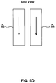
- FIGS. 5A-5D depict the moment of the free layer 504 as rotating by 180 degrees (as depicted in FIGS. 5A-5D ).
- FIG. 5B depicts the free layer 504 as having rotated 180 degrees with respect to FIG. 5A .
- FIG. 5D depicts the free layer 504 as having rotated 180 degrees with respect to FIG. 5C .
- the moment of the free layer 504 rotates by angles much smaller than 180 degrees, and the angle increases with the magnetic fields.
- a lapping plate 230 As a lapping plate 230 is damaged by scratches created during the diamond charging process or lapping process, or due to large cluster of diamonds embedded into the plate 230 or some other types of damage, it ( 230 ) will exert more mechanical stress on a read sensor 246 . This can cause the moment of the pinning layer 502 to reverse its ( 502 ) direction (also commonly known as a “flipped pinning layer 502 ”) as depicted in FIGS. 5C and 5D .
- the arrow for the pinning layer 502 as depicted in FIGS. 5C and 5D are pointing downwards (e.g., flipped) whereas in FIGS. 5A and 5B the arrows are pointing upwards.
- the amplitude of the magnetic signal from the platter can be used for evaluating the quality of a lapping plate 230 .
- the amplitude of the magnetic signal from the platter can be used for determining whether the moment of the pinning layer 502 has reversed.
- FIGS. 6A , and 6 B depict using amplitude of the magnetic signal to evaluate the quality of a lapping plate 230 , according to embodiments of the present invention.
- an apparatus that generates a magnetic signal with a known value can be used for determining whether the amplitude has reversed.
- the apparatus can include a coil that generates a magnetic signal of a known value.
- the slider 240 is surrounded by a coil 600 that generates a magnetic signal H (e.g., an external field) with a known value.
- a magnetic signal H e.g., an external field
- the coil 600 can be above or below the lapping plate 230 .
- the coil 600 can be inside the perimeter of the lapping plate 230 or outside the perimeter of the lapping plate 230 .
- the read sensor 246 detects the magnetic signal H generated by the coil 600 and the amplitude in response to the magnetic signal H is measured, according to one embodiment. If the pinning layer 502 has not been damaged by the lapping plate 230 , then the resistance R will be in-phase with the magnetic signal H generated by the coil 600 as depicted in FIG. 7A , according to one embodiment. However, if the pinning layer 502 has been reversed by the lapping plate 230 , then the resistance R will be out-of-phase with the magnetic signal H as depicted in FIG. 7B , according to another embodiment.
- amplitude can be measured as dR/R where dR is the change in resistance in response to the magnetic signal H, and R is the average resistance.
- dR is the change in resistance in response to the magnetic signal H
- R is the average resistance.
- the amplitude is positive as depicted in FIG. 7A .
- the amplitude is negative (e.g., reversed amplitude) as depicted in FIG. 7B .
- the amplitude dR/R is positive and is equal to 0.8 Ohm/40 Ohm-2.0%
- FIG. 7B the resistance has changed 180 degrees out-of-phase as a result of the magnetic field H changing.
- the percent of sliders with reversed pinning layers 502 can be used to evaluate the quality of a lapping plate 230 .
- the sliders from a single wafer can be analyzed to determine what percent of the sliders had reversed pinning layers 502 , according to another embodiment.
- FIG. 7C depicts the percent of sliders from a single wafer, where the percentage of sliders which have reversed pinning layers varies between lapping plates, according to an embodiment. As depicted in FIG. 7C , each point is the average over a plurality of sliders, such as 16 sliders for example. Some of the sliders were lapped with a lapping plate 1 and some of the slides were lapped with a lapping plate 2 . As depicted in FIG.
- lapping plate 1 resulted in approximately 14% (at point 710 ) of the sliders having reversed pinning layers 502 and lapping plate 2 resulted in approximately 3.5% (at point 720 ) of the sliders having reversed pinning layers 502 . Therefore, lapping plate 1 has worse quality than lapping plate 2 . According to one embodiment, if a lapping plate causes a certain percentage, such as 4% as depicted in 7 C, or more sliders to have a reversed a pinning layer, then the lapping plate has inadequate quality. In this case, the lapping plate 2 can be replaced with a new lapping plate.
- the percentage of sliders with reversed pinning layers 502 is largely dependent on the design of the head and the quality of the head.
- the criteria that is chosen for evaluating the quality of a lapping plate is related to the design and structure of a head. For example, although FIG. 7C depicts 4% as the criteria, another percentage may be used for a head with a different design and structure.
- the information receiver 210 receives information 250 that indicates the amplitude of the magnetic signal, according to one embodiment, and the quality determiner 220 uses amplitude to evaluate the quality of a lapping plate 230 while the lapping plate 230 is being used to lap a slider 240 , according to another embodiment.
- the information receiver 210 can receive a measurement of the amplitude or more than one measurement of the amplitude for a slider 240 over time.
- the quality determiner 220 can use the one or more measurements of the amplitude to determine whether amplitude has reversed.
- the quality determiner 220 can use the amplitude to calculate the percent of sliders with reversed pinning layers 502 (also commonly known as “flip rate”) as depicted in FIG. 7C . Further the quality determiner 220 can use the calculated percent of sliders to determine whether the lapping plate has inadequate quality based on the criteria described herein. The quality determiner 220 can compare the calculated percent of sliders with reversed pinning layers 502 to the chosen criteria and determine whether the lapping plate is adequate or not, according to embodiments described herein. More specifically, as depicted in FIG. 7C , plate 1 can be replaced since plate 1 resulted in more than 4% of the sliders that were lapped with plate 1 having reversed pinning layers 502 .
- FIG. 8 depicts a flowchart 800 for a method of evaluating the quality of a lapping plate, according to embodiments of the present invention.
- flowchart 800 depicts a flowchart 800 for a method of evaluating the quality of a lapping plate, according to embodiments of the present invention.
- steps in flowchart 800 may be performed in an order different than presented, and that not all of the steps in flowchart 800 may be performed.
- step 810 information that indicates the quality of a lapping plate is received while the lapping plate is being used to lap a slider 240 .
- information 250 indicating the quality of the lapping plate 230 is received by the information receiver 210 associated with the apparatus 200 .
- the information 250 can indicate the amount of resistance associated with the slider 240 and/or the information 250 can indicate the amplitude of a magnetic signal detected by a read sensor 246 .
- the information receiver 210 can receive a measurement of the amount of resistance R for a slider 240 or more than one measurement of the resistance R for a slider 240 over time. In another example, the information receiver 210 can receive a measurement of the amplitude or more than one measurement of the amplitude for a slider 240 over time.
- the information is used to evaluate the quality of the lapping plate while the lapping plate is being used to lap the slider 240 .
- the information 250 indicating the quality of the lapping plate 230 is provided to the quality determiner 250 which evaluates the quality of the lapping plate 230 based on the information 250 while the lapping plate 230 is being used to lap the slider 240 .
- the quality determiner 220 can use the one or more measurements of the resistance R to determine whether the resistance R is fluctuating.
- the quality determiner 220 can calculate an average of more than one measurement of resistance R as depicted in FIG. 4A , a sigma/mean as depicted in FIG. 4B , and/or a histogram as depicted in FIG. 4C .
- the quality determiner 220 can use the resistance R to determine whether the lapping plate has inadequate quality based on the criteria described herein. Examples of criteria include, but are not limited to, determining that the resistance R drops by approximately 1% or more or determining that the sigma/mean measurement of resistance fluctuates by 1% or more.
- the lapping plate 230 can be replaced if it ( 230 ) has inadequate quality.
- the quality determiner 220 can use amplitude to calculate the percent of sliders with reversed pinning layers 502 as depicted in FIG. 7C . Further, the quality determiner 220 can use the calculated percent of sliders which have reversed amplitude to determine whether the lapping plate has inadequate quality based on the criteria described herein. Examples of criteria include, but are not limited to, determining whether a slider has caused 4% or more sliders to have reversed pinning layers. The lapping plate 230 can be replaced if it ( 230 ) has inadequate quality.
- embodiments of the present invention can also be used for reducing the probability of damage to a write head 248 as well.
Abstract
Description
Claims (19)
Priority Applications (1)
| Application Number | Priority Date | Filing Date | Title |
|---|---|---|---|
| US11/289,930 US7914362B2 (en) | 2005-11-30 | 2005-11-30 | Method of evaluating the quality of a lapping plate |
Applications Claiming Priority (1)
| Application Number | Priority Date | Filing Date | Title |
|---|---|---|---|
| US11/289,930 US7914362B2 (en) | 2005-11-30 | 2005-11-30 | Method of evaluating the quality of a lapping plate |
Publications (2)
| Publication Number | Publication Date |
|---|---|
| US20070123150A1 US20070123150A1 (en) | 2007-05-31 |
| US7914362B2 true US7914362B2 (en) | 2011-03-29 |
Family
ID=38088137
Family Applications (1)
| Application Number | Title | Priority Date | Filing Date |
|---|---|---|---|
| US11/289,930 Expired - Fee Related US7914362B2 (en) | 2005-11-30 | 2005-11-30 | Method of evaluating the quality of a lapping plate |
Country Status (1)
| Country | Link |
|---|---|
| US (1) | US7914362B2 (en) |
Cited By (2)
| Publication number | Priority date | Publication date | Assignee | Title |
|---|---|---|---|---|
| US20150062746A1 (en) * | 2013-09-04 | 2015-03-05 | Seagate Technology Llc | In-situ lapping plate mapping device |
| US9387568B1 (en) * | 2013-02-27 | 2016-07-12 | Western Digital Technologies, Inc. | Systems and methods for correcting fabrication error in magnetic recording heads using magnetic write width measurements |
Families Citing this family (3)
| Publication number | Priority date | Publication date | Assignee | Title |
|---|---|---|---|---|
| US8169754B2 (en) * | 2007-12-31 | 2012-05-01 | Hitachi Global Storage Technologies, Netherlands, B.V. | Dedicated noncorrosive smear detector |
| US9343084B2 (en) | 2012-03-14 | 2016-05-17 | Western Digital Technologies, Inc. | Systems and methods for correcting slider parallelism error using compensation lapping |
| US8834661B1 (en) | 2013-02-27 | 2014-09-16 | Western Digital Technologies, Inc. | Row bar ring-to-ring transfer using single-sided adhesive film and vacuum |
Citations (35)
| Publication number | Priority date | Publication date | Assignee | Title |
|---|---|---|---|---|
| JPS6352968A (en) | 1986-08-20 | 1988-03-07 | Fujitsu Ltd | Automatic polishing device |
| JPH0349004A (en) | 1989-07-17 | 1991-03-01 | Hitachi Ltd | Manufacture of multiple magnetic head and integral grinder used in manufacturing |
| US5632669A (en) | 1995-05-26 | 1997-05-27 | Censtor Corporation | Interactive method for lapping transducers |
| US5722155A (en) | 1996-01-11 | 1998-03-03 | Seagate Technology, Inc. | Machining guide method for magnetic recording reproduce heads |
| US5735036A (en) * | 1994-12-16 | 1998-04-07 | International Business Machines Corporation | Lapping process for minimizing shorts and element recession at magnetic head air bearing surface |
| US5772493A (en) | 1995-07-31 | 1998-06-30 | Read-Rite Corporation | Method and apparatus for controlling the lapping of magnetic heads |
| JPH10269530A (en) | 1997-03-27 | 1998-10-09 | Sony Corp | Manufacturing method of magneto-resistance effect type head |
| JP3049004B2 (en) | 1997-05-08 | 2000-06-05 | インターナショナル・ビジネス・マシーンズ・コーポレイション | Method and apparatus for installing and configuring a computer program |
| JP2000202768A (en) | 1999-01-12 | 2000-07-25 | Tdk Corp | Polishing method and device and manufacture of thin film magnetic head |
| US6163954A (en) * | 1998-07-23 | 2000-12-26 | Alps Electric Co., Ltd. | Method of producing a slider |
| US6170149B1 (en) | 1996-04-30 | 2001-01-09 | Fujitsu Limited | Magnetoresistive type magnetic head and method of manufacturing the same and apparatus for polishing the same |
| US6196897B1 (en) | 1997-04-08 | 2001-03-06 | Fujitsu Limted | Automatic lapping method and a lapping apparatus using the same |
| US20020012204A1 (en) | 2000-05-25 | 2002-01-31 | Zine-Eddine Boutaghou | Lapping sensor for recording heads |
| US6347983B1 (en) | 1999-06-09 | 2002-02-19 | Seagate Technology Llc | ELG for both MRE sensor height and resistance monitoring |
| US20020063984A1 (en) | 2000-11-28 | 2002-05-30 | Mcclellan Brett A. | Pin layer reversal detection |
| US20020126421A1 (en) | 2001-03-08 | 2002-09-12 | Hitachi, Ltd. | Lapping apparatus, magnetic head and method of manufacturing the same |
| US6497798B1 (en) | 2000-10-11 | 2002-12-24 | Jds Uniphase Inc. | Controllably monitoring and reducing a material |
| JP2003011054A (en) | 2001-06-29 | 2003-01-15 | Hitachi Ltd | Polishing method for magnetic head and device thereof |
| US20030026046A1 (en) | 2001-07-31 | 2003-02-06 | Hitachi, Ltd. | Magnetic head and method of manufacturing the same |
| JP2003039319A (en) | 2001-07-25 | 2003-02-13 | Sony Corp | Lapping device |
| US6531399B2 (en) | 2000-10-26 | 2003-03-11 | Hitachi, Ltd. | Polishing method |
| US6585559B1 (en) * | 1999-04-02 | 2003-07-01 | Engis Corporation | Modular controlled platen preparation system and method |
| US6609948B1 (en) | 2000-11-27 | 2003-08-26 | International Business Machines Corporation | Method of making an electronic lapping guide (ELG) for lapping a read sensor |
| US20030200041A1 (en) * | 2002-04-22 | 2003-10-23 | International Business Machines Corporation | In-situ stripe height calibration of magneto resistive sensors |
| US6679760B2 (en) | 2001-02-23 | 2004-01-20 | Sae Magnetics (H.K.) Ltd. | Lapping method of magnetic head slider and lapping method of bar |
| US20040088137A1 (en) * | 2002-10-30 | 2004-05-06 | International Business Machines Corporation | Lapping plate topography system |
| US20040097173A1 (en) * | 2002-11-19 | 2004-05-20 | International Business Machines Corporation | Onboard multiphase electronic lapping guide design for MR heads |
| US20040176013A1 (en) | 2003-03-04 | 2004-09-09 | International Business Machines Corporation | Multi-chambered, compliant apparatus for restraining workpiece and applying variable pressure thereto during lapping to improve flatness characteristics of workpiece |
| US20050040206A1 (en) * | 2000-12-22 | 2005-02-24 | Senco Products, Inc. | Control module for flywheel operated hand tool |
| US20050059323A1 (en) * | 2003-09-16 | 2005-03-17 | Hitachi Global Storage Technologies Netherlands B.V. | System and apparatus for predicting plate lapping properties to improve slider fabrication yield |
| US20050191946A1 (en) * | 2004-02-27 | 2005-09-01 | Beaucage Jacey R. | Methods and apparatus for controlling the lapping of a slider based on an amplitude of a readback signal produced from an externally applied magnetic field |
| US6949004B1 (en) | 2002-09-06 | 2005-09-27 | Maxtor Corporation | Method for reducing pole and alumina recession on magnetic recording heads |
| US7014530B2 (en) * | 2003-09-29 | 2006-03-21 | Hitachi Global Storage Technologies Netherlands B.V. | Slider fabrication system for sliders with integrated electrical lapping guides |
| US20060067004A1 (en) * | 2004-09-30 | 2006-03-30 | Hitachi Global Storage Technologies Netherlands B.V. | Critically exposed lapping of magnetic sensors for target signal output |
| US7100266B2 (en) * | 2001-05-16 | 2006-09-05 | Seagate Technology Llc | Method of forming a beveled writing pole of a perpendicular writing element |
-
2005
- 2005-11-30 US US11/289,930 patent/US7914362B2/en not_active Expired - Fee Related
Patent Citations (36)
| Publication number | Priority date | Publication date | Assignee | Title |
|---|---|---|---|---|
| JPS6352968A (en) | 1986-08-20 | 1988-03-07 | Fujitsu Ltd | Automatic polishing device |
| JPH0349004A (en) | 1989-07-17 | 1991-03-01 | Hitachi Ltd | Manufacture of multiple magnetic head and integral grinder used in manufacturing |
| US5735036A (en) * | 1994-12-16 | 1998-04-07 | International Business Machines Corporation | Lapping process for minimizing shorts and element recession at magnetic head air bearing surface |
| US5632669A (en) | 1995-05-26 | 1997-05-27 | Censtor Corporation | Interactive method for lapping transducers |
| US5772493A (en) | 1995-07-31 | 1998-06-30 | Read-Rite Corporation | Method and apparatus for controlling the lapping of magnetic heads |
| US5722155A (en) | 1996-01-11 | 1998-03-03 | Seagate Technology, Inc. | Machining guide method for magnetic recording reproduce heads |
| US6170149B1 (en) | 1996-04-30 | 2001-01-09 | Fujitsu Limited | Magnetoresistive type magnetic head and method of manufacturing the same and apparatus for polishing the same |
| JPH10269530A (en) | 1997-03-27 | 1998-10-09 | Sony Corp | Manufacturing method of magneto-resistance effect type head |
| US6196897B1 (en) | 1997-04-08 | 2001-03-06 | Fujitsu Limted | Automatic lapping method and a lapping apparatus using the same |
| JP3049004B2 (en) | 1997-05-08 | 2000-06-05 | インターナショナル・ビジネス・マシーンズ・コーポレイション | Method and apparatus for installing and configuring a computer program |
| US6163954A (en) * | 1998-07-23 | 2000-12-26 | Alps Electric Co., Ltd. | Method of producing a slider |
| JP2000202768A (en) | 1999-01-12 | 2000-07-25 | Tdk Corp | Polishing method and device and manufacture of thin film magnetic head |
| US6585559B1 (en) * | 1999-04-02 | 2003-07-01 | Engis Corporation | Modular controlled platen preparation system and method |
| US6347983B1 (en) | 1999-06-09 | 2002-02-19 | Seagate Technology Llc | ELG for both MRE sensor height and resistance monitoring |
| US6760197B2 (en) | 2000-05-25 | 2004-07-06 | Seagate Technology Llc | Lapping sensor for recording heads having guide element kept |
| US20020012204A1 (en) | 2000-05-25 | 2002-01-31 | Zine-Eddine Boutaghou | Lapping sensor for recording heads |
| US6497798B1 (en) | 2000-10-11 | 2002-12-24 | Jds Uniphase Inc. | Controllably monitoring and reducing a material |
| US6531399B2 (en) | 2000-10-26 | 2003-03-11 | Hitachi, Ltd. | Polishing method |
| US6609948B1 (en) | 2000-11-27 | 2003-08-26 | International Business Machines Corporation | Method of making an electronic lapping guide (ELG) for lapping a read sensor |
| US20020063984A1 (en) | 2000-11-28 | 2002-05-30 | Mcclellan Brett A. | Pin layer reversal detection |
| US20050040206A1 (en) * | 2000-12-22 | 2005-02-24 | Senco Products, Inc. | Control module for flywheel operated hand tool |
| US6679760B2 (en) | 2001-02-23 | 2004-01-20 | Sae Magnetics (H.K.) Ltd. | Lapping method of magnetic head slider and lapping method of bar |
| US20020126421A1 (en) | 2001-03-08 | 2002-09-12 | Hitachi, Ltd. | Lapping apparatus, magnetic head and method of manufacturing the same |
| US7100266B2 (en) * | 2001-05-16 | 2006-09-05 | Seagate Technology Llc | Method of forming a beveled writing pole of a perpendicular writing element |
| JP2003011054A (en) | 2001-06-29 | 2003-01-15 | Hitachi Ltd | Polishing method for magnetic head and device thereof |
| JP2003039319A (en) | 2001-07-25 | 2003-02-13 | Sony Corp | Lapping device |
| US20030026046A1 (en) | 2001-07-31 | 2003-02-06 | Hitachi, Ltd. | Magnetic head and method of manufacturing the same |
| US20030200041A1 (en) * | 2002-04-22 | 2003-10-23 | International Business Machines Corporation | In-situ stripe height calibration of magneto resistive sensors |
| US6949004B1 (en) | 2002-09-06 | 2005-09-27 | Maxtor Corporation | Method for reducing pole and alumina recession on magnetic recording heads |
| US20040088137A1 (en) * | 2002-10-30 | 2004-05-06 | International Business Machines Corporation | Lapping plate topography system |
| US20040097173A1 (en) * | 2002-11-19 | 2004-05-20 | International Business Machines Corporation | Onboard multiphase electronic lapping guide design for MR heads |
| US20040176013A1 (en) | 2003-03-04 | 2004-09-09 | International Business Machines Corporation | Multi-chambered, compliant apparatus for restraining workpiece and applying variable pressure thereto during lapping to improve flatness characteristics of workpiece |
| US20050059323A1 (en) * | 2003-09-16 | 2005-03-17 | Hitachi Global Storage Technologies Netherlands B.V. | System and apparatus for predicting plate lapping properties to improve slider fabrication yield |
| US7014530B2 (en) * | 2003-09-29 | 2006-03-21 | Hitachi Global Storage Technologies Netherlands B.V. | Slider fabrication system for sliders with integrated electrical lapping guides |
| US20050191946A1 (en) * | 2004-02-27 | 2005-09-01 | Beaucage Jacey R. | Methods and apparatus for controlling the lapping of a slider based on an amplitude of a readback signal produced from an externally applied magnetic field |
| US20060067004A1 (en) * | 2004-09-30 | 2006-03-30 | Hitachi Global Storage Technologies Netherlands B.V. | Critically exposed lapping of magnetic sensors for target signal output |
Non-Patent Citations (3)
| Title |
|---|
| Appl. Phys. A 77,923-932 (2003) "On the advanced lapping process in the precision finishin of thin-film magnetic recording heads for rigid disc drives". |
| IEEE Mag-37 n.2, pp. 974.ff "The effect of Lapping Method on the Thermal Reliability of a GMR Head Based on Black's Equation". |
| IEEE Mag-37 n.4, pp. 1713.ff "Resistance Measurement of GMR Heads as a Magnetic Performance Indicator". |
Cited By (3)
| Publication number | Priority date | Publication date | Assignee | Title |
|---|---|---|---|---|
| US9387568B1 (en) * | 2013-02-27 | 2016-07-12 | Western Digital Technologies, Inc. | Systems and methods for correcting fabrication error in magnetic recording heads using magnetic write width measurements |
| US20150062746A1 (en) * | 2013-09-04 | 2015-03-05 | Seagate Technology Llc | In-situ lapping plate mapping device |
| US9286930B2 (en) * | 2013-09-04 | 2016-03-15 | Seagate Technology Llc | In-situ lapping plate mapping device |
Also Published As
| Publication number | Publication date |
|---|---|
| US20070123150A1 (en) | 2007-05-31 |
Similar Documents
| Publication | Publication Date | Title |
|---|---|---|
| US8619529B1 (en) | Methods and devices for enhanced adaptive margining based on channel threshold measure | |
| US7384327B2 (en) | Method for grinding a bar of thin film magnetic elements utilizing a plurality of resistive films | |
| US8094396B1 (en) | Media defect scan | |
| JP3723651B2 (en) | Method and apparatus for restoring the thermal response of a magnetoresistive head | |
| US7633694B2 (en) | Method and apparatus for quantifying stress and damage in magnetic heads | |
| US7914362B2 (en) | Method of evaluating the quality of a lapping plate | |
| US6239936B1 (en) | Method and apparatus for calibrating a thermal response of a magnetoresistive element | |
| US7613587B2 (en) | Method for compensating for acceleration vector offset, recording medium storing program for executing the method, and related apparatus | |
| US6696832B2 (en) | Method and apparatus for testing transducer heads in magnetic storage systems | |
| US8047894B2 (en) | Apparatus for evaluating the quality of a lapping plate | |
| US20020018508A1 (en) | Glide head for asperity detection | |
| US6822815B2 (en) | Abnormal magnetoresistive element detection for a disc drive | |
| US7054084B2 (en) | Method, apparatus and program storage device for sensing increased resistance changes in an MR element to detect MR sensor events | |
| US20020066177A1 (en) | Method for manufacturing magneto-resistive effect type magnetic heads | |
| JP5439064B2 (en) | Degradation detection method for magnetic head and magnetic disk inspection apparatus | |
| US6556006B1 (en) | Method for magneto-resistive head electrostatic popping detection | |
| US20070245814A1 (en) | Magnetic disk defect test method, protrusion test device and glide tester | |
| US7260887B2 (en) | Apparatus for controlling the lapping of a slider based on an amplitude of a readback signal produced from an externally applied magnetic field | |
| US6918815B2 (en) | System and apparatus for predicting plate lapping properties to improve slider fabrication yield | |
| JP2007305286A (en) | Magnetic disk defect test method, protrusion test device, and glide tester | |
| US20080235938A1 (en) | Inductance test chip for helical wrap around shield perpendicular magnetic recording | |
| US6633459B2 (en) | Functional recording-head on-slider lap monitor | |
| US20050059322A1 (en) | Method of predicting plate lapping properties to improve slider fabrication yield | |
| US7580759B2 (en) | Systems and methods for in-situ recording head burnishing | |
| JP2008192270A (en) | Testing method and device of tunneling magnetoresistive effect element |
Legal Events
| Date | Code | Title | Description |
|---|---|---|---|
| AS | Assignment |
Owner name: HITACHI GLOBAL STORAGE TECHNOLOGIES NETHERLANDS B. Free format text: ASSIGNMENT OF ASSIGNORS INTEREST;ASSIGNORS:BUNCH, RICHARD DALE;CRAWFORTH, LINDEN JAMES;PADILLA, EDUARDO;AND OTHERS;SIGNING DATES FROM 20050517 TO 20051128;REEL/FRAME:017845/0418 Owner name: HITACHI GLOBAL STORAGE TECHNOLOGIES NETHERLANDS B. Free format text: ASSIGNMENT OF ASSIGNORS INTEREST;ASSIGNORS:BUNCH, RICHARD DALE;CRAWFORTH, LINDEN JAMES;PADILLA, EDUARDO;AND OTHERS;REEL/FRAME:017845/0418;SIGNING DATES FROM 20050517 TO 20051128 |
|
| FEPP | Fee payment procedure |
Free format text: PAYOR NUMBER ASSIGNED (ORIGINAL EVENT CODE: ASPN); ENTITY STATUS OF PATENT OWNER: LARGE ENTITY |
|
| STCF | Information on status: patent grant |
Free format text: PATENTED CASE |
|
| AS | Assignment |
Owner name: HGST, NETHERLANDS B.V., NETHERLANDS Free format text: CHANGE OF NAME;ASSIGNOR:HGST, NETHERLANDS B.V.;REEL/FRAME:029341/0777 Effective date: 20120723 Owner name: HGST NETHERLANDS B.V., NETHERLANDS Free format text: CHANGE OF NAME;ASSIGNOR:HITACHI GLOBAL STORAGE TECHNOLOGIES NETHERLANDS B.V.;REEL/FRAME:029341/0777 Effective date: 20120723 |
|
| FPAY | Fee payment |
Year of fee payment: 4 |
|
| AS | Assignment |
Owner name: WESTERN DIGITAL TECHNOLOGIES, INC., CALIFORNIA Free format text: ASSIGNMENT OF ASSIGNORS INTEREST;ASSIGNOR:HGST NETHERLANDS B.V.;REEL/FRAME:040819/0450 Effective date: 20160831 |
|
| FEPP | Fee payment procedure |
Free format text: MAINTENANCE FEE REMINDER MAILED (ORIGINAL EVENT CODE: REM.); ENTITY STATUS OF PATENT OWNER: LARGE ENTITY |
|
| LAPS | Lapse for failure to pay maintenance fees |
Free format text: PATENT EXPIRED FOR FAILURE TO PAY MAINTENANCE FEES (ORIGINAL EVENT CODE: EXP.); ENTITY STATUS OF PATENT OWNER: LARGE ENTITY |
|
| STCH | Information on status: patent discontinuation |
Free format text: PATENT EXPIRED DUE TO NONPAYMENT OF MAINTENANCE FEES UNDER 37 CFR 1.362 |
|
| FP | Lapsed due to failure to pay maintenance fee |
Effective date: 20190329 |