US7945374B2 - Method and apparatus for characterizing fuel injector performance to reduce variability in fuel injection - Google Patents
Method and apparatus for characterizing fuel injector performance to reduce variability in fuel injection Download PDFInfo
- Publication number
- US7945374B2 US7945374B2 US12/315,767 US31576708A US7945374B2 US 7945374 B2 US7945374 B2 US 7945374B2 US 31576708 A US31576708 A US 31576708A US 7945374 B2 US7945374 B2 US 7945374B2
- Authority
- US
- United States
- Prior art keywords
- fuel injector
- fuel
- accordance
- engine
- performance
- Prior art date
- Legal status (The legal status is an assumption and is not a legal conclusion. Google has not performed a legal analysis and makes no representation as to the accuracy of the status listed.)
- Active, expires
Links
Images


Classifications
-
- F—MECHANICAL ENGINEERING; LIGHTING; HEATING; WEAPONS; BLASTING
- F02—COMBUSTION ENGINES; HOT-GAS OR COMBUSTION-PRODUCT ENGINE PLANTS
- F02D—CONTROLLING COMBUSTION ENGINES
- F02D41/00—Electrical control of supply of combustible mixture or its constituents
- F02D41/008—Controlling each cylinder individually
- F02D41/0085—Balancing of cylinder outputs, e.g. speed, torque or air-fuel ratio
-
- F—MECHANICAL ENGINEERING; LIGHTING; HEATING; WEAPONS; BLASTING
- F02—COMBUSTION ENGINES; HOT-GAS OR COMBUSTION-PRODUCT ENGINE PLANTS
- F02D—CONTROLLING COMBUSTION ENGINES
- F02D41/00—Electrical control of supply of combustible mixture or its constituents
- F02D41/20—Output circuits, e.g. for controlling currents in command coils
-
- F—MECHANICAL ENGINEERING; LIGHTING; HEATING; WEAPONS; BLASTING
- F02—COMBUSTION ENGINES; HOT-GAS OR COMBUSTION-PRODUCT ENGINE PLANTS
- F02D—CONTROLLING COMBUSTION ENGINES
- F02D41/00—Electrical control of supply of combustible mixture or its constituents
- F02D41/24—Electrical control of supply of combustible mixture or its constituents characterised by the use of digital means
- F02D41/2406—Electrical control of supply of combustible mixture or its constituents characterised by the use of digital means using essentially read only memories
- F02D41/2425—Particular ways of programming the data
- F02D41/2429—Methods of calibrating or learning
- F02D41/2432—Methods of calibration
- F02D41/2435—Methods of calibration characterised by the writing medium, e.g. bar code
-
- F—MECHANICAL ENGINEERING; LIGHTING; HEATING; WEAPONS; BLASTING
- F02—COMBUSTION ENGINES; HOT-GAS OR COMBUSTION-PRODUCT ENGINE PLANTS
- F02D—CONTROLLING COMBUSTION ENGINES
- F02D41/00—Electrical control of supply of combustible mixture or its constituents
- F02D41/20—Output circuits, e.g. for controlling currents in command coils
- F02D2041/202—Output circuits, e.g. for controlling currents in command coils characterised by the control of the circuit
- F02D2041/2055—Output circuits, e.g. for controlling currents in command coils characterised by the control of the circuit with means for determining actual opening or closing time
-
- F—MECHANICAL ENGINEERING; LIGHTING; HEATING; WEAPONS; BLASTING
- F02—COMBUSTION ENGINES; HOT-GAS OR COMBUSTION-PRODUCT ENGINE PLANTS
- F02D—CONTROLLING COMBUSTION ENGINES
- F02D41/00—Electrical control of supply of combustible mixture or its constituents
- F02D41/20—Output circuits, e.g. for controlling currents in command coils
- F02D2041/202—Output circuits, e.g. for controlling currents in command coils characterised by the control of the circuit
- F02D2041/2058—Output circuits, e.g. for controlling currents in command coils characterised by the control of the circuit using information of the actual current value
Definitions
- the present invention relates to fuel injectors for internal combustion engines; more particularly, to an inherent variation in the performance within a group of individual fuel injectors; and most particularly, to a method and apparatus for reducing such performance variations among a plurality of standard fuel injectors assembled into a multiple-cylinder engine by measuring each fuel injector prior to installation and providing the individual calibration information to an engine control module.
- Direct Injection Gasoline (DIG) fuel injection in an internal combustion engine involves injection of fuel directly into each combustion chamber.
- a high range of fuel flows is required to meet engine power demands ranging from very low idle speed to peak power.
- U.S. Pat. No. 5,241,858 is directed to a dynamic flow calibration of a fuel injector by selective diversion of magnetic flux from the working gap.
- the fuel injector has a dynamic flow calibration mechanism in which a control rod that extends between and enters holes in both the stator and the armature is selectively positioned to divert some of the magnetic flux from the axial working gap between the stator and the armature such that the diverted magnetic flux passes through the control rod directly between the stator and the armature without passing through the working gap.
- the fuel injector is calibrated by selectively positioning the control rod so that the diverted flux which is conducted between the stator and the armature is conducted through the control rod without passing through the working gap.
- U.S. Pat. No. 5,392,995 similarly is directed to a fuel injector calibration through directed leakage flux.
- the solenoid includes a tubular pole piece with an area of increased reluctance adjacent the working surface of the pole piece and an adjustment rod disposed for movement within the high reluctance region to thereby vary the location at which the high reluctance region begins.
- Leakage flux from the high reluctance region of the magnetic circuit may be directed to operate on a particular element of the magnetic circuit based on the location of the adjustment rod thereby allowing the leakage flux to exert a force on the element and to thereby vary the dynamic response characteristics of the injector.
- Neither of these inventions addresses the problem of an injector having a specified and fixed hold current that is inadequate for reliably keeping the injector valve fully open for the desired length of time under all operating conditions.
- both of these inventions require very substantial modifications to a standard fuel injector, including an expensive and cumbersome moveable rod and rod-positioning mechanism.
- What is needed in the art is a method for providing to an ECM a characterization of the electrical and mechanical properties of each fuel injector in an internal combustion engine, such that the ECM can vary, via an algorithm, one or more electrical parameters for each injector to equalize the fuel injection characteristics of all the injectors in the engine.
- the method should be readily applicable to standard prior art fuel injectors and not require special modifications to the fuel injectors.
- a method for equalizing fuel injector flows among a plurality of fuel injectors in an internal combustion engine includes the steps of:
- FIG. 1 is a histogram showing relative contributions to variation in hold force for prior art fuel injectors
- FIG. 2 is a graph of injector solenoid force as a function of flux linkage, showing adjustment in force in accordance with the present invention
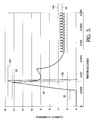
- FIG. 3 is a graph of applied current as a function of time during a fuel injector operating cycle, showing adjustment of peak current/time and hold current in accordance with the present invention
- FIG. 4 is a graph of applied voltage and current during a performance cycle of an injector defining a variety of driver parameters that may be employed and calibration constants assigned to the injector, in accordance with the invention.
- FIG. 5 is a schematic diagram of a process for adjusting a fuel injector's wave form and operating cycle in accordance with the present invention.
- histogram 10 shows the contributions of various materials and manufacturing tolerances to the deviation in force from nominal for a standard prior art DIG fuel injector. It is seen that the total spread 12 of all deviations is nearly 18 N (+7.34 N to ⁇ 10.35 N); the corresponding tolerance spread 14 of RMS values is nearly 8 N (+3.4 N to ⁇ 4.4).
- This range of variation in fuel injector opening force is too great to meet the need for cylinder-to-cylinder uniformity in fuel flow in modern engines in which a fixed nominal hold current is supplied to all fuel injector solenoids.
- the supplied hold current is selected to meet the electromechanical characteristics of each individual fuel injector.
- FIG. 2 This relationship is shown graphically in FIG. 2 , as is also the basis for the invention, wherein force F 18 is shown as a function of flux linkage ⁇ .
- force F 18 is shown as a function of flux linkage ⁇ .
- the desired or nominal solenoid holding force F is, for example, 40 N
- an aim flux linkage 20 is required in response to a standard test current C (not shown).
- the force F of which the solenoid is capable of holding at that current is proportionally less 24 (in the exemplary case shown, F is about 34 N).
- force F is directly related to the current C applied to a solenoid, it will be seen that the application of higher current to a given sub-standard fuel injector can increase the applied force, within reasonable limits.
- a graph is shown of current C in amperes during a 5 performance cycle of a prior art fuel injector.
- Curve 30 shows a rapid increase in current to about 14.5 amperes 31 during a “boost” time period 32 wherein a high current (actually a high voltage, causing a proportionally high current) is applied to open the fuel injector valve as rapidly as possible.
- the current is reduced to a nominal hold current level 34 of about 3.0 amperes and is hysteretically controlled about that level to provide a hold force on the fuel injector valve during the principal fuel injection period.
- the peak opening current 31 may be increased by increasing the boost current itself to a higher peak level 131 and/or by extending 132 the boost time period.
- the increase in boost current is by the same percent as the hold current increase.
- the target hold current for each injector may be determined in at least any of several methods contemplated by the invention, as follows:
- Two measurements may be used to determine the appropriate driver (current) calibration values. These include a mechanical measurement (such as a pop-off pressure, dynamic flow, or release current) in concert with an electrical measurement (such as the flux linkage measurement or coil resistance measurement).
- a mechanical measurement such as a pop-off pressure, dynamic flow, or release current
- an electrical measurement such as the flux linkage measurement or coil resistance measurement.
- the flux linkage data may be used further to provide information to calibrate other driver parameters in addition to the hold current parameter.
- driver parameters such as, for example, hold current ( 50 ), peak current ( 52 ), peak current time ( 54 ), boost voltage level ( 56 ), boost time ( 58 ), bypass current level ( 60 ), bypass current time ( 62 ), reverse current level ( 64 ), reverse current time ( 66 ) and fast transition time (peak bypass ( 68 ) and bypass hold ( 70 )), may be adjusted to meet a specified transient flux linkage profile.
- hold current 50
- peak current 52
- peak current time 54
- boost voltage level 56
- boost time 58
- bypass current level 60
- bypass current time 62
- reverse current level 64
- reverse current time 66
- fast transition time peak bypass ( 68 ) and bypass hold ( 70 )
- an exemplary method 200 in accordance with the present invention is shown schematically for equalizing fuel injector flows among a plurality of fuel injectors in an internal combustion engine.
- the flow path shown is for an exemplary fuel injector in a family of fuel injectors.
- method 200 The following steps may be included in method 200 :
- Measurement 202 The electrical and/or mechanical performance characteristics of the fuel injector are measured as described above.
- the performance characteristics measured in 202 are stored as by printing in code including individual fuel injector identification on the injector body and the fuel injector is transported to an engine assembly facility. Alternatively, the characteristics may be read directly into a computer file, and only identification printed on the fuel injector.
- Assembly on Engines 206 The fuel injector is assembled into an engine 208 , along with the appropriate number of other fuel injectors.
- Reading of Code 210 The fuel injector identification and characteristics data, if not already filed as in Step 2, are read and entered into a computer file.
- Temporary storage 212 The assembled engine is sent to in-process storage.
- Assembly on Vehicle 214 The engine is assembled into a vehicle during vehicle assembly.
- ECM Assembly on Vehicle 216 The Engine Control Module is assembled into the vehicle during vehicle assembly and is connected to the fuel injectors.
- the method includes steps 202 , 204 , and 218 .
- the engine is now ready for using 222 the characterization data in an algorithm to adjust one or more parameters such as hold current, peak current, peak current time, boost voltage level, boost time, bypass current level, bypass current time, reverse current level, reverse current time and fast transition time for each fuel injector during each fuel injection cycle.
Abstract
Description
-
- a) characterizing the electrical and/or mechanical performance of each fuel injector as a function of at least one of coil resistance, transient magnetic flux linkage response, and pintle closing response;
- b) imprinting characterization data or a pointer thereto on each fuel injector;
- c) reading the imprinted data into a control computer, preferably at the time of engine assembly or sub-assembly; and
- d) using the characterization data in an algorithm to adjust at least one electrical parameter for each fuel injector in an assembled engine during each fuel injection cycle.
V=IR+dλ/dt (Eq. 1)
Rearranging, flux linkage is found by integrating voltage over time:
Λ=0
The force F exerted by the solenoid and the flux linkage λ are related by the equation:
F=(k 1λ2)/A (Eq. 3)
where k is a parameter based on the ratio of magnetizing to total flux and the coil turns, and A is the cross-sectional area of the airgap.
Claims (11)
Priority Applications (1)
| Application Number | Priority Date | Filing Date | Title |
|---|---|---|---|
| US12/315,767 US7945374B2 (en) | 2008-12-05 | 2008-12-05 | Method and apparatus for characterizing fuel injector performance to reduce variability in fuel injection |
Applications Claiming Priority (1)
| Application Number | Priority Date | Filing Date | Title |
|---|---|---|---|
| US12/315,767 US7945374B2 (en) | 2008-12-05 | 2008-12-05 | Method and apparatus for characterizing fuel injector performance to reduce variability in fuel injection |
Publications (2)
| Publication Number | Publication Date |
|---|---|
| US20100145597A1 US20100145597A1 (en) | 2010-06-10 |
| US7945374B2 true US7945374B2 (en) | 2011-05-17 |
Family
ID=42232016
Family Applications (1)
| Application Number | Title | Priority Date | Filing Date |
|---|---|---|---|
| US12/315,767 Active 2029-03-11 US7945374B2 (en) | 2008-12-05 | 2008-12-05 | Method and apparatus for characterizing fuel injector performance to reduce variability in fuel injection |
Country Status (1)
| Country | Link |
|---|---|
| US (1) | US7945374B2 (en) |
Cited By (4)
| Publication number | Priority date | Publication date | Assignee | Title |
|---|---|---|---|---|
| US20120022766A1 (en) * | 2010-07-22 | 2012-01-26 | Delphi Technologies Holding S.Arl | Method of providing trim data for a fuel injection device |
| US20140238354A1 (en) * | 2013-02-25 | 2014-08-28 | Denso Corporation | Fuel injection controller and fuel injection system |
| CN107110052A (en) * | 2014-12-25 | 2017-08-29 | 日立汽车系统株式会社 | Fuel injection control valve device |
| CN107304727A (en) * | 2016-04-22 | 2017-10-31 | 通用汽车环球科技运作有限责任公司 | The method and apparatus that optimal drive signal for electromagnetic start actuator is controlled |
Families Citing this family (9)
| Publication number | Priority date | Publication date | Assignee | Title |
|---|---|---|---|---|
| US20120080536A1 (en) * | 2010-10-05 | 2012-04-05 | GM Global Technology Operations LLC | Method for controlling a fuel injector |
| US8938350B2 (en) * | 2011-06-29 | 2015-01-20 | Electro-Motive Diesel, Inc. | Skip fire fuel injection system and method |
| EP2816212A1 (en) * | 2013-06-21 | 2014-12-24 | Continental Automotive GmbH | Method and device for controlling an injector |
| EP2873842B1 (en) * | 2013-11-14 | 2018-02-28 | Delphi Automotive Systems Luxembourg SA | Control of Actuation of Fuel Injector |
| US9822747B2 (en) | 2014-01-21 | 2017-11-21 | MAGNETI MARELLI S.p.A. | Method to control an electromagnetic actuator of an internal combustion engine |
| WO2015143109A1 (en) * | 2014-03-20 | 2015-09-24 | GM Global Technology Operations LLC | Optimum current drive for actuator control |
| JP7110736B2 (en) * | 2018-05-31 | 2022-08-02 | 株式会社デンソー | Control device for fuel injection valve and fuel injection system |
| CN108979874B (en) * | 2018-07-24 | 2020-09-29 | 潍柴动力股份有限公司 | Control method and control device of electromagnetic valve and gas engine |
| CN113202669B (en) * | 2021-06-10 | 2022-07-15 | 哈尔滨工程大学 | Multi-objective optimization method for performance of electric control oil injector |
Citations (11)
| Publication number | Priority date | Publication date | Assignee | Title |
|---|---|---|---|---|
| US5241858A (en) | 1991-12-09 | 1993-09-07 | Siemens Automotive L.P. | Dynamic flow calibration of a fuel injector by selective diversion of magnetic flux from the working gap |
| US5392995A (en) | 1994-03-07 | 1995-02-28 | General Motors Corporation | Fuel injector calibration through directed leakage flux |
| US6360161B1 (en) * | 2000-05-04 | 2002-03-19 | Bombardier Motor Corporation Of America | Method and system for fuel injector coefficient installation |
| US6588398B1 (en) * | 2001-12-18 | 2003-07-08 | Caterpillar Inc | Automated electronic trim for a fuel injector |
| US20030130784A1 (en) * | 2000-11-28 | 2003-07-10 | Peltier Daniel E. | Method and apparatus for identifying parameters of an engine component for assembly and programming |
| US20040128055A1 (en) * | 2002-12-27 | 2004-07-01 | Caterpillar, Inc. | Method for estimating fuel injector performance |
| US6775607B2 (en) * | 2000-11-13 | 2004-08-10 | Bombardier Recreational Products Inc. | Diagnostic system and method to temporarily adjust fuel quantity delivered to a fuel injected engine |
| US6801847B2 (en) * | 2002-12-27 | 2004-10-05 | Caterpillar Inc | Method for estimating fuel injector performance |
| US6892569B2 (en) * | 2001-12-20 | 2005-05-17 | Caterpillar Inc. | In-chassis engine compression release brake diagnostic test and electronic control module using the same |
| US7004150B2 (en) * | 2003-08-12 | 2006-02-28 | Siemens Diesel Systems Technology Vdo | Control valve for fuel injector and method of use |
| US7025047B2 (en) * | 2001-09-04 | 2006-04-11 | Caterpillar Inc. | Determination of fuel injector performance in chassis |
-
2008
- 2008-12-05 US US12/315,767 patent/US7945374B2/en active Active
Patent Citations (13)
| Publication number | Priority date | Publication date | Assignee | Title |
|---|---|---|---|---|
| US5241858A (en) | 1991-12-09 | 1993-09-07 | Siemens Automotive L.P. | Dynamic flow calibration of a fuel injector by selective diversion of magnetic flux from the working gap |
| US5392995A (en) | 1994-03-07 | 1995-02-28 | General Motors Corporation | Fuel injector calibration through directed leakage flux |
| US6360161B1 (en) * | 2000-05-04 | 2002-03-19 | Bombardier Motor Corporation Of America | Method and system for fuel injector coefficient installation |
| US6775607B2 (en) * | 2000-11-13 | 2004-08-10 | Bombardier Recreational Products Inc. | Diagnostic system and method to temporarily adjust fuel quantity delivered to a fuel injected engine |
| US20030130784A1 (en) * | 2000-11-28 | 2003-07-10 | Peltier Daniel E. | Method and apparatus for identifying parameters of an engine component for assembly and programming |
| US6671611B1 (en) * | 2000-11-28 | 2003-12-30 | Bombardier Motor Corporation Of America | Method and apparatus for identifying parameters of an engine component for assembly and programming |
| US7136743B2 (en) * | 2000-11-28 | 2006-11-14 | Brp Us Inc. | Method and apparatus for identifying parameters of an engine component for assembly and programming |
| US7025047B2 (en) * | 2001-09-04 | 2006-04-11 | Caterpillar Inc. | Determination of fuel injector performance in chassis |
| US6588398B1 (en) * | 2001-12-18 | 2003-07-08 | Caterpillar Inc | Automated electronic trim for a fuel injector |
| US6892569B2 (en) * | 2001-12-20 | 2005-05-17 | Caterpillar Inc. | In-chassis engine compression release brake diagnostic test and electronic control module using the same |
| US6801847B2 (en) * | 2002-12-27 | 2004-10-05 | Caterpillar Inc | Method for estimating fuel injector performance |
| US20040128055A1 (en) * | 2002-12-27 | 2004-07-01 | Caterpillar, Inc. | Method for estimating fuel injector performance |
| US7004150B2 (en) * | 2003-08-12 | 2006-02-28 | Siemens Diesel Systems Technology Vdo | Control valve for fuel injector and method of use |
Cited By (14)
| Publication number | Priority date | Publication date | Assignee | Title |
|---|---|---|---|---|
| US8886858B2 (en) * | 2010-07-22 | 2014-11-11 | Delphi International Operations Luxembourg S.A.R.L. | Method of providing trim data for a fuel injection device |
| US20120022766A1 (en) * | 2010-07-22 | 2012-01-26 | Delphi Technologies Holding S.Arl | Method of providing trim data for a fuel injection device |
| US20180245534A1 (en) * | 2013-02-25 | 2018-08-30 | Denso Corporation | Fuel injection controller and fuel injection system |
| US9476376B2 (en) * | 2013-02-25 | 2016-10-25 | Denso Corporation | Fuel injection controller and fuel injection system |
| US20170009689A1 (en) * | 2013-02-25 | 2017-01-12 | Denso Corporation | Fuel injection controller and fuel injection system |
| US9982616B2 (en) * | 2013-02-25 | 2018-05-29 | Denso Corporation | Fuel injection controller and fuel injection system |
| US20140238354A1 (en) * | 2013-02-25 | 2014-08-28 | Denso Corporation | Fuel injection controller and fuel injection system |
| US10598114B2 (en) * | 2013-02-25 | 2020-03-24 | Denso Corporation | Fuel injection controller and fuel injection system |
| CN107110052A (en) * | 2014-12-25 | 2017-08-29 | 日立汽车系统株式会社 | Fuel injection control valve device |
| EP3239503A4 (en) * | 2014-12-25 | 2018-08-22 | Hitachi Automotive Systems, Ltd. | Fuel injection valve control device |
| US10247125B2 (en) | 2014-12-25 | 2019-04-02 | Hitachi Automotive Systems, Ltd. | Fuel injection valve control device |
| CN107110052B (en) * | 2014-12-25 | 2020-03-03 | 日立汽车系统株式会社 | Fuel injection valve control device |
| CN107304727A (en) * | 2016-04-22 | 2017-10-31 | 通用汽车环球科技运作有限责任公司 | The method and apparatus that optimal drive signal for electromagnetic start actuator is controlled |
| CN107304727B (en) * | 2016-04-22 | 2021-03-09 | 通用汽车环球科技运作有限责任公司 | Method and apparatus for optimal drive signal control for electromagnetically activated actuators |
Also Published As
| Publication number | Publication date |
|---|---|
| US20100145597A1 (en) | 2010-06-10 |
Similar Documents
| Publication | Publication Date | Title |
|---|---|---|
| US7945374B2 (en) | Method and apparatus for characterizing fuel injector performance to reduce variability in fuel injection | |
| US5831809A (en) | Method for controlling an electromagnetic actuator with compensation for changes in ohmic resistance of the electromagnet coil | |
| EP2850307B1 (en) | Method for monitoring an injection valve | |
| DE102008031477B4 (en) | Engine system with a direct injection system and method for controlling fuel injection timing | |
| JP6114697B2 (en) | Method for controlling an internal combustion engine | |
| US8827175B2 (en) | Method and device for the calibration of fuel injectors | |
| CN102472187A (en) | Method and device for operating an internal combustion engine | |
| US20060201488A1 (en) | Method for controlling a solenoid valve | |
| US10634082B2 (en) | Fuel injector calibration method and apparatus | |
| WO2011003704A1 (en) | Determining the closing time of a fuel injection valve based on evaluating the actuation voltage | |
| US20090071443A1 (en) | Fuel Injection Control Apparatus for Internal Combustion Engine | |
| KR20150005911A (en) | Determining the movement behaviour over time of a fuel injector on the basis of an evaluation of the temporal progression of various electrical measurement variables | |
| US8332125B2 (en) | Method for controlling at least one solenoid valve | |
| DE10020896A1 (en) | Position detection method for armature of electromagnetic setting device e..g. for gas changing valve of IC engine | |
| US7686000B2 (en) | Controller and method for controlling an ignition coil | |
| JP2010249069A (en) | Fuel injection control device | |
| US5878722A (en) | Method and device for controlling an electromagnetic load | |
| US20170204804A1 (en) | Method for determining an opening delay of a fuel injector | |
| US20100193719A1 (en) | Device and method for controlling an electromagnetic valve | |
| JP2001505637A (en) | Apparatus and method for detecting movement of fuel injector | |
| KR20020033416A (en) | Internal combustion engine fuel injection apparatus and control method thereof | |
| DE112018002791T5 (en) | Fuel injection control device for an internal combustion engine | |
| US20110120420A1 (en) | Method for determining a characteristics map of the injection quantity via an electric variable of an electrically triggered fuel injector | |
| CN107407219B (en) | Injection valve for injecting a fluid, use of an injection valve, and method for producing an injection valve | |
| DE112016005465T5 (en) | Fuel injection control device for internal combustion engine |
Legal Events
| Date | Code | Title | Description |
|---|---|---|---|
| AS | Assignment |
Owner name: DELPHI TECHNOLOGIES, INC.,MICHIGAN Free format text: ASSIGNMENT OF ASSIGNORS INTEREST;ASSIGNORS:KEEGAN, KEVIN R.;KREFTA, RONALD J.;SIGNING DATES FROM 20081126 TO 20081201;REEL/FRAME:022005/0599 Owner name: DELPHI TECHNOLOGIES, INC., MICHIGAN Free format text: ASSIGNMENT OF ASSIGNORS INTEREST;ASSIGNORS:KEEGAN, KEVIN R.;KREFTA, RONALD J.;SIGNING DATES FROM 20081126 TO 20081201;REEL/FRAME:022005/0599 |
|
| STCF | Information on status: patent grant |
Free format text: PATENTED CASE |
|
| FPAY | Fee payment |
Year of fee payment: 4 |
|
| AS | Assignment |
Owner name: DELPHI TECHNOLOGIES IP LIMITED, BARBADOS Free format text: ASSIGNMENT OF ASSIGNORS INTEREST;ASSIGNOR:DELPHI TECHNOLOGIES, INC.;REEL/FRAME:045127/0546 Effective date: 20171129 |
|
| MAFP | Maintenance fee payment |
Free format text: PAYMENT OF MAINTENANCE FEE, 8TH YEAR, LARGE ENTITY (ORIGINAL EVENT CODE: M1552); ENTITY STATUS OF PATENT OWNER: LARGE ENTITY Year of fee payment: 8 |
|
| MAFP | Maintenance fee payment |
Free format text: PAYMENT OF MAINTENANCE FEE, 12TH YEAR, LARGE ENTITY (ORIGINAL EVENT CODE: M1553); ENTITY STATUS OF PATENT OWNER: LARGE ENTITY Year of fee payment: 12 |