US7954272B2 - Adjustable firearm supports and associated methods of use and manufacture - Google Patents
Adjustable firearm supports and associated methods of use and manufacture Download PDFInfo
- Publication number
- US7954272B2 US7954272B2 US12/117,668 US11766808A US7954272B2 US 7954272 B2 US7954272 B2 US 7954272B2 US 11766808 A US11766808 A US 11766808A US 7954272 B2 US7954272 B2 US 7954272B2
- Authority
- US
- United States
- Prior art keywords
- plate
- assembly
- firearm
- bipod
- stock mount
- Prior art date
- Legal status (The legal status is an assumption and is not a legal conclusion. Google has not performed a legal analysis and makes no representation as to the accuracy of the status listed.)
- Expired - Fee Related
Links
Images


Classifications
-
- F—MECHANICAL ENGINEERING; LIGHTING; HEATING; WEAPONS; BLASTING
- F41—WEAPONS
- F41A—FUNCTIONAL FEATURES OR DETAILS COMMON TO BOTH SMALLARMS AND ORDNANCE, e.g. CANNONS; MOUNTINGS FOR SMALLARMS OR ORDNANCE
- F41A23/00—Gun mountings, e.g. on vehicles; Disposition of guns on vehicles
- F41A23/02—Mountings without wheels
- F41A23/08—Bipods
- F41A23/10—Bipods adjustable
Definitions
- the present disclosure is directed to support assemblies for firearms. More specifically, several aspects of the disclosure are directed to adjustable bipod assemblies that removably attach to and support firearms.
- Shooters often use firearm rests or supports to steady a firearm during target practice, accuracy testing, and hunting. Holding a firearm without a stable support may limit the shooter's ability to accurately fire the firearm. Many shooters accordingly use a support in an attempt to reduce or eliminate human movement inherent from holding the firearm. For example, shooters may place the forestock of a rifle on a front support and the buttstock of the rifle on a rear support. Alternatively, shooters may hold the buttstock and use a support only for the forestock of the rifle.
- bipod support One type of support for the forestock of a rifle is a bipod support.
- Conventional bipod supports include attachment mechanisms that can be fixedly attached or removably attached to the forestock of the rifle. These bipods can also include legs that can be folded generally parallel to the barrel of the rifle for storage or to facilitate carrying the rifle. Examples of bipod supports are included in U.S. Pat. Nos. 3,327,422; 4,470,216; 4,625,620; 4,903,425; and 5,711,103. Examples of bipod supports are also available from the following companies: Harris Engineering, Inc., Barlow, Ky. 42024 (www.harrisbipods.com); and Keng's Firearms Specialty, Inc., 875 Wharton Drive, SW, Atlanta, Ga. 30336 (www.versapod.com).
- FIG. 1 is an isometric view of a firearm operably coupled to a firearm support assembly configured in accordance with an embodiment of the disclosure.
- FIG. 2A is an isometric view
- FIG. 2B is a rear view
- FIG. 2C is a left side view
- FIG. 2D is a bottom plan view of the firearm support assembly of FIG. 1 .
- FIG. 3 is an isometric view of a portion of a stock mount assembly configured in accordance with an embodiment of the disclosure.
- FIG. 4 is an exploded isometric view of an attachment assembly configured in accordance with an embodiment of the disclosure.
- FIG. 5 is an exploded isometric view of a leg of the firearm support assembly configured in accordance with an embodiment of the disclosure.
- FIG. 6A is an isometric view and FIG. 6B is a partial side view of a firearm support assembly configured in accordance with another embodiment of the disclosure.
- FIG. 7 is an isometric view of a stock mount assembly configured in accordance with an embodiment of the disclosure.
- FIGS. 8 and 9 are exploded isometric views of the stock mount assembly of FIG. 7 .
- FIG. 10 is a cross-sectional view of the stock mount assembly configured in accordance with an embodiment of the disclosure.
- the bipod assembly includes several components that are made from a corrosion resistant nonferrous metal or alloy such as titanium or a titanium alloy.
- the bipod assembly includes a stock mount assembly configured to support a forestock of the firearm, and an attachment assembly carried by the stock mount assembly and configured to releasably attach to the forestock of the firearm.
- the stock mount assembly can include a titanium support plate, and at least a portion of the attachment assembly can be titanium.
- the bipod assembly further includes first and second legs operably coupled to the support plate, wherein at least a portion of each of the legs can also be titanium.
- the legs can pivot between a stowed position in which the legs are generally parallel to a longitudinal axis of the firearm, and an extended position in which the legs are generally transverse to the longitudinal axis of the firearm.
- the titanium components of the bipod assembly provide a relatively lightweight bipod assembly that has corrosion resistant properties without requiring exterior surface treatment.
- the bipod assembly includes a stock mount assembly that is rotatable relative to a longitudinal axis of the firearm.
- the bipod assembly includes a first plate that is operably coupled to a second plate, and a cam lever that moves a tension screw in a direction generally parallel to the longitudinal axis of the firearm.
- the tension screw is movable between a first position that locks the first plate with reference to the second plate, and a second position that allows the first plate to rotate with reference to the second plate.
- the bipod assembly also includes an attachment assembly that is carried by the stock mount assembly and that is configured to releasably attach to the forestock.
- the bipod assembly further includes first and second adjustable legs extending from the stock mount assembly.
- the bipod assembly can include a stock mount assembly including a first plate operably coupled to a second plate, and first means for locking the first plate with reference to the second plate.
- the bipod assembly also includes an attachment assembly carried by the stock mount assembly.
- the attachment assembly is configured to attach to the forestock of the firearm and includes second means for adjusting a tension of the attachment assembly.
- the bipod assembly further includes a pair of legs operably coupled to the first plate. Each leg includes third means for adjusting a length of the leg.
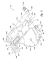
- FIG. 1 is an isometric view of a firearm 2 that is attached to a firearm support assembly 100 (“support 100 ”) configured in accordance with one embodiment of the disclosure.
- the support 100 includes a stock mount assembly 110 that is configured to releasably attach to the forestock 4 of the firearm 2 .
- Support members or legs 150 (identified individually as a first leg 150 a and a second leg 150 b ) extend from the stock mount assembly 110 and provide an adjustable support for the forestock 4 of the firearm 2 .
- the legs 150 are movable between a support position as shown in FIG. 1 , and a stowed position as shown in broken lines.
- the legs 150 extend in a direction generally perpendicular to a longitudinal axis 5 of the firearm 2 when they are in the support position.
- the legs 150 can pivot relative to the stock mount assembly 110 to move into the stowed position in a direction generally parallel to the longitudinal axis 5 of the firearm 2 .
- FIG. 2A is an isometric view
- FIG. 2B is a rear view
- FIG. 2C is a left side view
- FIG. 2D is a bottom plan view of the support 100 of FIG. 1 .
- the illustrated embodiment includes a pad 209 carried by the stock mount assembly 110 .
- the pad 209 is configured to mate with the forestock 4 of the firearm 2 ( FIG. 1 ) and can be made from a durable non-marring material (e.g., rubber, elastomer, foam, leather, etc.).
- the pad 209 is eliminated and a top surface of the stock mount assembly 110 is configured to mate with the forestock 4 of the firearm 2 ( FIG. 1 ).
- An adjustment assembly 230 is operably coupled to the stock mount assembly 110 to releasably attach to the firearm 2 .
- the attachment assembly 230 includes attachment members 232 (individually identified as a first attachment member 232 a and a second attachment member 232 b ) extending through the stock mount assembly 110 to engage a sling swivel stud or other component of the firearm 2 .
- the support 100 further includes biasing members or springs 258 (individually identified as a first spring 258 a and a second spring 258 b ) operably coupled to the stock mount assembly 110 and each of the legs 150 .
- Each spring 258 retains the corresponding leg 150 in the extended position or in the stowed position ( FIG. 1 ).
- each leg 150 includes an upper leg portion 252 (individually identified as a first upper leg portion 252 a and a second upper leg portion 252 b ) that slidably receives a corresponding lower leg portion 254 (individually identified as a first lower leg portion 254 a and a second lower leg portion 254 b ).
- the lower leg portions 254 can independently slide into and out of the upper leg portions 252 to adjust the height of the support 100 or accommodate uneven terrain.
- the support 100 also includes locking assemblies 251 (individually identified as a first locking assembly 251 a and a second locking assembly 251 b ) that are operably coupled to the corresponding upper leg portions 252 to retain the lower leg portions 254 at a desired position extending axially from the upper leg portions 252 .
- Each lower leg portion 254 also includes a foot 255 (individually identified as a first foot 255 a and a second foot 255 b ) that can be made from a non-slip or resilient material (e.g., rubber, plastic, etc.).
- each foot 255 can be attached to the corresponding lower leg portion 254 without the use of a mechanical fastener.
- the feet 255 can be attached to the lower leg portions 254 with an adhesive.
- the support 100 is relatively light weight with reference to the firearm 2 ( FIG. 1 ). More specifically, and as described in detail below, several of the components of the support 100 can be made from a corrosion resistant nonferrous metal or alloy such as titanium or aluminum to allow the support 100 to be lighter than conventional firearm supports.
- titanium is intended to include pure titanium and titanium alloyed materials.
- the titanium components of the support 100 are also corrosion resistant by virtue of the material properties of titanium. Accordingly, certain components or all of the components of the support 100 can be made from titanium to take advantage of the high strength to weight ratio of titanium and to avoid surface treatment processing steps (e.g., anodizing) for corrosion purposes. In other embodiments, however, portions or all of the support 100 can be made from other materials that are suitable for firearm supports (e.g., aluminum, steel, alloys, etc.).
- FIG. 3 shows an isometric view of an attachment portion of the stock mount assembly 110 .
- the stock mount assembly 110 includes a support plate 308 that is configured to receive the forestock 4 of the firearm 2 , as well as support the legs 150 and attachment assembly 230 .
- the support plate 308 includes side forestock support portions 312 (individually identified as a first forestock support portion 312 a and a second forestock support portion 312 b ) extending from a middle portion 311 in a generally U-shaped configuration to receive the forestock 4 .
- the forestock support portions 312 can also be configured to carry one or more pads 209 ( FIG. 2A ).
- the stock mount assembly 110 further includes leg support portions 314 (individually identified as a first leg support portion 314 a and a second leg support portion 314 b ) extending at an angle from the corresponding forestock support portions 312 .
- Each leg support portion 314 includes a leg attachment opening 315 (individually identified as a first leg attachment opening 315 a and a second leg attachment opening 315 b ) to receive a fastener (e.g., screw, bolt, rivet, etc.) for pivotal attachment to the corresponding leg 150 .
- Each leg support portion 314 also includes spring flanges 318 (individually identified as a first spring flange 318 a and a second spring flange 318 b ).
- Each spring flange 318 extends generally parallel from the corresponding leg support portion 314 and includes a post 319 (individually identified as a first post 319 a and a second post 319 b ) to be operably coupled to the corresponding springs 258 ( FIG. 2A ).
- Each leg support portion 314 also includes a brace flange 316 (individually identified as a first brace flange 316 a and a second brace flange 316 b ).
- the brace flanges 316 extend from the leg support portions 314 toward each other and are attached to a brace member 320 .
- the brace member 320 is formed from a generally flat or planar piece of material.
- the support plate 308 and the brace member 320 can be made from a stamping manufacturing process. In this manner, the brace member 320 can be made from the parent stamping material of the support plate 308 .
- the support plate 308 and the brace member 320 can be made from a corrosion resistant nonferrous metal or alloy such as titanium or aluminum.
- the planar brace member 320 in the illustrated embodiment provides a generally flat first mounting surface 301 for a first label 302 (shown in broken lines).
- the first label 302 can include a plaque or decal with reference indicia such as a company logo, model name, specifications, advertising, etc.
- the first label 302 can be attached to the first mounting surface 301 of the brace member 320 with an adhesive, mechanical fastener, etc.
- One advantage of positioning the first label 302 on the generally planar brace member 320 is that the first mounting surface 301 is the most visible when the attached firearm 2 is standing up in a gun rack. For example, when the legs 150 are in the stowed position and the firearm 2 is resting vertically in a gun rack, the first mounting surface 301 faces outwardly from the firearm 2 to display the first label 302 .
- the support plate 308 further includes stop portions 322 (individually identified as a first stop portion 322 a and a second stop portion 322 b ) extending from the middle portion 311 .
- Each stop portion 322 includes a stop surface 323 (individually identified as a first stop surface 323 a and a second stop surface 323 b ) that is configured to contact and stop the pivotal movement of the legs 150 when they in the stowed position (as shown in FIG. 1 in broken lines).
- the support plate 308 also includes an attachment assembly mounting portion 324 extending generally perpendicularly from the middle portion 311 between the stop portions 322 .
- the attachment assembly mounting portion 324 includes a slot 325 for receiving the adjustment assembly 230 ( FIG. 2A ), and a generally planar or flat second mounting surface 327 that is configured to receive a second label 303 .
- the second label 303 can be generally similar to the first label 302 and attached to the second mounting surface 327 with an adhesive, mechanical fastener, etc.
- the stock mount assembly 110 also includes a screw plate 321 attached to the middle portion 311 of the support plate 308 proximate to the attachment assembly mounting portion 324 .
- the middle portion 311 also includes an opening 313 extending therethrough proximate to the screw plate 321 to receive the attachment members 232 of the attachment assembly 230 ( FIG. 2A ).
- the screw plate 321 is configured to provide a reinforcing material to adjust a tension of the attachment assembly 230 .
- the stock mount assembly 110 can be configured to omit the screw plate 321 .
- the support plate 308 and associated portions described above can be formed from a single piece of material. More specifically, the support plate 308 can include a single piece of material that can be stamped and bent into the desired shape. As noted above, the brace member 320 can also be stamped from the same material as the support plate 308 . In one embodiment, the support plate 308 and all of its integral portions can be formed from a corrosion resistant nonferrous metal or alloy such as titanium, aluminum or a titanium alloy. In other embodiments, however, these components can be formed from other materials suitable for forming a firearm support 100 , such as steel or other ferrous metals and alloys.
- FIG. 4 shows an exploded isometric view of the attachment assembly 230 .
- the attachment assembly 230 includes tension arms 440 (individually identified as a first tension arm 440 a and a second tension arm 440 b ) operably coupled to side arms 432 (individually identified as a first side arm 432 a and a second side arm 432 b ). More specifically, the tension arms 440 are attached to each other with multiple fasteners 447 (shown in FIG. 4 as rivets) inserted through corresponding opening 441 . A ring clip 448 is inserted through corresponding second openings 442 in the tension arms 440 .
- Each tension arm 440 includes a curved middle portion 443 (individually identified as a first middle portion 443 a and a second middle portion 443 b ) configured to accommodate a locknut 446 and having a slot 445 (individually identified as a first slot 445 a and a second slot 445 b ) formed therein.
- the locknut 446 is captured between the curved portions 443 in the slots 445 , and a tension member or thumb screw 447 is threadably engaged with the locknut 446 .
- a retainer pin 438 operably couples the side arms 432 to the tension arms 440 . More specifically, the retainer pin 438 is received in openings 443 in the tension arms 440 , as well as in openings 435 in the side arms 432 .
- a generally U-shaped retainer plate 436 is positioned around the side arms 432 and the end portions of the retainer pin 438 . In this manner, each side arm 432 can independently pivot with reference to the tension arms 440 .
- Engagement pins 434 (individually identified as a first engagement pin 434 a and a second engagement pin 434 b ) are retained (e.g., press-fit) into corresponding openings 433 in the side arms 432 to engage and retain the forestock 4 of the firearm 2 ( FIG. 1 ).
- the side arms 432 and associated engagement pins 434 can be releasably attached to a sling swivel stud (not shown) on the forestock 4 .
- the attachment assembly 230 is moveable relative to the stock mount assembly 110 to attach the support 100 to the firearm 2 .
- the tension arms 440 can pivot with reference to the attachment assembly mounting portion 324 of the support plate 308 to move the side arms 432 into and out of the attachment opening 313 ( FIG. 3 ).
- the thumb screw 447 can be rotated in the locknut 446 to draw the side arms 432 and corresponding engagement pins 434 attached to the forestock 4 toward the support plate 308 . More specifically, an end portion of the thumb screw 447 can contact and rotate against the screw plate 321 ( FIG. 3 ).
- the locknut 446 travels axially along the thumb screw 447 away from the support plate 308 to pull the side arms 432 and increase the retention force of the engagement pins 434 .
- the captured locknut 446 prevents the thumb screw 447 from backing out or inadvertently loosening when the attachment assembly is attached to a firearm 2 .
- the locknut prevents the thumb screw 447 from backing out during operation of the firearm, while the firearm support is in a stored position, or while the firearm support is supporting the firearm.
- the locknut 446 can be a standard hardware fastener with internal threads.
- the locknut 446 can be a hexagonal locknut with metallic or nylon threads.
- the thumb screw 447 of the illustrated embodiment threadably engages a locknut 446 having predictable threads that can be formed from high-quality material. Moreover, forming the locknut 446 does not require extensive manufacturing processes because a standard hardware fastener can be used. In other embodiments, the locknut 446 can be made from other materials suitable for engaging the thumb screw 447 , such as, for example, nylon, plastic, or other non-metallic materials.
- FIG. 5 shows an exploded isometric view of one of the legs 150 .
- the upper leg portion 252 has a generally cylindrical hollow body 553 .
- the body 553 is made from a corrosion resistant nonferrous metal or alloy such as titanium and is formed rolling and welding process. More specifically, the body 553 can include a welded seam 554 extending axially along the body.
- the body 553 also includes an attachment opening 560 that is configured to receive a fastener (not shown) to attach the leg 150 to the stock mount assembly 110 .
- the leg 150 also includes a spring retaining member 556 that is configured to operably couple the body 553 of the upper leg portion 252 to the spring 258 ( FIG. 2A ).
- the spring retaining member 258 includes a generally circular opening 555 having a diameter that is slightly greater than an outer diameter of the body 553 .
- the opening 555 includes a generally planar portion 557 .
- the spring retaining member 556 also includes and extension portion 558 having an aperture 559 that is configured to releasably attach to the spring 258 .
- the opening 555 of the spring retaining member 556 is angled with reference to the body 553 of the upper leg portion 252 to prevent the spring retaining member 556 from sliding axially along the body 553 of the upper leg portion 252 .
- the hollow body 553 is configured to slidably receive and retain at least a portion of the lower leg portion 254 .
- the upper leg portion 252 includes a groove 564 having a first inner diameter ID 1 (not shown) that is less than a second inner diameter ID 2 (not shown) of the body 553 .
- the groove 564 can be formed in a rolling manufacturing process in the upper leg portion 252 . In other embodiments, however, the groove 564 can be formed using other manufacturing methods.
- the lower leg portion 254 includes a first slot 578 that is configured to receive and retain bushings or retention members 576 (individually identified as a first retention member 576 a and a second retention member 576 b ).
- the retention members 576 When the retention members 576 are positioned in the first slot 578 , the retention members 576 have a combined outer diameter OD (not shown) that is greater than the first inner diameter ID 1 of the groove 564 but less than the second inner diameter ID 2 of the body 553 of the upper leg portion 252 . In this manner, the lower leg portion 254 can slide within the upper leg portion 252 to extend therefrom, until the retaining members 576 contact the groove 564 in the body 553 of the upper leg portion 252 .
- the lower leg portion 254 can be locked in incremental positions extending out of the upper leg portion 252 .
- the lower leg portion 254 includes a plurality of spaced apart slots or channels 580 (individually identified as first through fifth channels 580 a - 580 e ).
- the leg 150 also includes a locking assembly 575 that removably engages the channels 580 .
- the locking assembly 575 can be removably attached to the end portion of the upper leg portion 252 .
- the locking assembly 575 includes a plunger housing 572 having an opening 573 that receives a spring-loaded plunger 574 .
- a retaining ring 566 is positioned on top of the plunger housing 572 and includes a flange 568 having an opening 569 that engages the plunger 574 .
- the retaining ring 566 also includes a tab 570 extending toward an interior portion of the retaining ring 566 .
- the tab 570 is configured to extend into the body 558 of the upper leg portion 252 through a corresponding slot 562 (shown in broken lines).
- the tab 570 is configured to engage one of the channels 580 as the lower leg portion 254 slides in or out of the upper leg portion 252 .
- the tab 570 disengages the slot 580 as the flange 568 of the retaining ring 566 is pushed toward the plunger 574 to depress the plunger 574 and move the entire retaining ring 566 .
- a lower portion of the plunger housing 572 can cover a lower edge 581 of the upper leg portion 252 . More specifically, a lower portion of the plunger housing 572 can have an inner diameter 579 that is smaller than the outer diameter of the body 553 of the upper leg portion 252 , and also smaller than the combined outer diameter OD of the retention members 576 . In this manner, the inner diameter 579 of the lower portion of the plunger housing 572 can act as a stop against the retention members 576 to limit the extension of the lower leg portion 254 from the upper leg portion 252 .
- the plunger housing 572 can have a die-cast geometry.
- the plunger housing 572 can include draft angles and parting lines suitable for die-casting manufacturing processes.
- One advantage of utilizing die-cast geometries for the plunger housing 572 is that the plunger housing 572 can be designed to be light weight plunger housing 572 .
- several of the components of the leg 150 illustrated in FIG. 5 can be made from light weight titanium or aluminum.
- the upper leg portion 252 , the lower leg portion 254 , the retaining ring 566 , the plunger 574 , and/or the retention members 576 can be made from aluminum, titanium or titanium alloys. In other embodiments, however, some or all of these components can be made from other suitable materials for firearm supports, for example, nonferrous metals or alloys, or ferrous metals or alloys.
- a further advantage of forming the upper leg portion 252 from nonferrous metal such as titanium is that the upper leg portion 252 can be attached to the stock mount assembly 110 without any reinforcement on or near the attachment opening 560 .
- the combination of an increased strength with light weight and corrosion resistance provides desirable advantages for a firearm support assembly.
- the light weight allows the support assembly to be easily carried while attached to the firearm; the corrosion resistance allows the firearm support assembly to be used in all weather conditions; and the increased strength provides a more durable firearm support.
- FIG. 6A shows an isometric of a firearm support 600 .
- the firearm support is generally similar in structure and function to the firearm support 100 described above with reference to FIGS. 1-5 .
- the illustrated firearm support 600 includes the attachment assembly 130 and adjustable legs 150 .
- the firearm support 600 includes a stock mount assembly 610 that is configured to rotate or swivel about the longitudinal axis 5 of the firearm 2 ( FIG. 1 ). More specifically, the stock mount assembly 610 is configured to rotate or swivel with reference to the legs 150 in directions indicated by the double-headed arrow 611 .
- FIG. 6B shows a partial side view of the firearm support 600 taken along the line 6 B- 6 B of FIG. 6A .
- the stock mount assembly 610 includes a first stock mount plate 611 having a first extension portion 612 and a second extension portion 614 .
- a swivel bushing 616 is operably coupled between the first extension portion 612 and the second extension portion 614 .
- a swivel bushing cap 618 retains the swivel bushing 616 in position with reference to the second extension portion 614 .
- the stock mount assembly 610 further includes a second stock mount plate 630 and a third stock mount plate 650 positioned between a cam lever 660 and the first extension portion 612 of the first stock mount plate 611 .
- the cam lever 660 is configured to move a tension screw (not shown in FIG. 6B ) relative to the swivel bushing 616 to lock or unlock the rotation of the stock mount assembly 610 .
- FIG. 7 shows an isometric view of the stock mount assembly 610 .
- the first stock mount plate 611 has a generally U-shaped configuration and carries pads 709 (individually identified as a first pad 709 a and a second pad 709 b ) to contact a firearm ( FIG. 1 ).
- a spring plate 770 (only a portion of which is visible in FIG. 7 ) is attached to the first stock mount plate 611 to bias the first stock mount plate 611 in a generally centered position with reference to the second stock mount plate 630 .
- the cam lever 660 is configured to move a cam bushing 762 that is coupled to the tension screw 778 . More specifically, in the position shown in FIG.
- the cam lever 660 pulls the cam bushing 762 to position the tension screw 778 so that the first stock mount plate 611 is in a locked position with reference to the second mount plate 630 .
- a contact surface 761 of the cam lever 660 contacts the third stock mount plate 650 . This movement changes the distance between the cam bushing 762 and the second stock mount plate 630 to move the tension screw 778 into the swivel bushing 616 and unlock the rotation of the second stock plate 630 with reference to the first stock mount plate 611 .
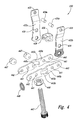
- FIG. 8 is an exploded isometric view of several components of the stock mount assembly 610 .
- the first stock mount plate 611 includes an attachment assembly mounting portion 824 and an attachment assembly opening 822 , each of which are configured to receive an attachment assembly generally similar in structure and function to the attachment assembly 230 described above with reference to FIGS. 2A-2D and 4 .
- the first extension portion 612 of the first stock mount plate 611 includes a generally circular first opening 813 having two spaced apart key portions 818 (only a second key portion 818 b is visible in FIG. 8 ).
- the key portions 818 each have a generally rectilinear shape extending from the first opening 813 . In other embodiments, however, the key portions 818 can have other shapes or configurations.
- the second extension portion 614 also includes a generally circular second opening 815 aligned with the first opening 813 .
- the first stock mount plate 611 also includes a spring plate attachment aperture 826 that is configured to be aligned with a corresponding aperture 827 on the spring plate 770 for attachment thereto (e.g., with a fastener).
- the spring plate 770 includes arms 872 (individually identified as a first arm 872 a and a second arm 872 b ) that are configured to contact the second stock mount plate 630 to bias the first stock mount plate 611 in a generally centered position with reference to the second stock mount plate 630 .
- the second stock mount plate 630 includes a generally circular opening 836 .
- the circular opening 836 has two spaced apart key portions 838 (individually identified as a first key portion 838 a and a second key portion 838 b ).
- the circular opening 836 and associated key portions 838 are configured to be generally aligned with the first opening 813 and corresponding key portions 818 of the first extension portion 612 of the first stock mount plate 611 .
- the second stock mount plate 630 also includes leg support portions 832 (individually identified as a first leg support portion 832 a and a second leg support portion 832 b ).
- Each leg support portion 832 includes leg attachment openings 835 (individually identified as a first leg attachment opening 835 a and a second leg attachment opening 835 b ) and a stop portion 834 (individually identified as a first stop portion 834 a and a second stop portion 834 b ).
- the leg attachment openings 835 are configured to receive a fastener (e.g., rivet, screw, bolt, etc.) to attach the corresponding legs 150
- the stop portions 834 are configured to provide a stop for the legs 150 in a stowed position.
- the third stock mount plate 650 includes a generally circular opening 854 that is configured to be aligned with the first opening 813 of the first extension portion 612 of the first stock mount plate 611 , as well as the opening 836 of the second stock mount plate 630 .
- the third stock mount 650 plate also includes angled side portions 852 (individually identified as a first angled side portion 852 a and a second angled side portion 852 b ) with associated attachment apertures 853 (individually identified as a first attachment aperture 853 a and a second attachment aperture 853 b ) to receive a protruding member (e.g., post, bolt, screw, etc.) for attachment to a spring ( FIG. 6A ).
- a protruding member e.g., post, bolt, screw, etc.
- FIG. 9 is an exploded isometric view of the stock mount assembly 610 .
- the stock mount assembly 610 includes a tension screw bushing 972 including a first end portion 973 having external threads and a second end portion 974 having internal threads.
- the tension screw bushing 972 is configured to fit within the cylindrical opening of the swivel bushing 616
- the second end portion 974 is configured to threadably engage a portion of the swivel bushing cap 618 (see, e.g., FIG. 10 ).
- the tension screw bushing 972 has a generally hollow and cylindrical body that is configured to receive the tension screw 778 and biasing members 976 (individually identified as a first biasing member 976 a and a second biasing member 976 b ).
- the tension screw 778 includes an opening 979 extending therethrough that is configured to receive a lock member 980 .
- the lock member 980 includes spaced apart end portions 982 (individually identified as a first end portion 982 a and a second end portion 982 b ) that are configured to correspond to the key portions 818 of the first extension portion 612 of the first stock mount plate 611 , as well as to the key portions 838 of the circular opening 836 of the second stock mount plate 630 .
- the stock mount assembly 610 also includes a bushing nut 966 that is configured to threadably engage the first end portion 973 of the tension screw bushing 972 .
- the cam bushing 762 includes an opening 965 that is configured to receive an end portion of the tension screw 778 , and a clip member 967 retains the cam bushing 762 on the end portion of the tension screw 778 .
- the cam busing 762 includes two arm members 964 (individually identified as a first arm member 964 a and a second arm member 964 b ) extending generally laterally from the opening 965 .
- the cam lever 660 has a generally Y-shaped configuration including two cam lever arms 961 (individually identified as a first cam lever arm 961 a and a second cam lever arm 961 b ).
- the cam lever arms 961 engage the corresponding arms 964 of the cam bushing 762 . As described in detail below, that the cam lever 660 pulls the cam bushing 762 and the attached tension screw 778 and corresponding lock member 980 to lock or unlock the rotation of the stock mount assembly 610 .
- FIG. 10 is a cross-sectional view of the assembled stock mount assembly 610 .
- the tension screw 778 extends through each of the first stock mount plate 611 , the second stock mount plate 630 , and the third stock mount plate 650 .
- the tension screw bushing 972 is positioned inside the swivel bushing 616 , and the first end portion 973 of the tension screw 778 is threadably engaged with the bushing nut 966 , and the second end portion 974 of the tension screw 778 is threadably engaged with the swivel bushing cap 618 .
- the tension screw bushing 972 includes a first cavity 1075 a and a second cavity 1075 b .
- the first cavity 1075 a encompasses the first biasing member 976 a surrounding the tension screw 778
- the second cavity encompasses the second biasing member 976 b also surrounding the tension screw 778 .
- the tension screw 778 is movable in the directions of the double headed arrow 1002 to unlock or lock the rotation of the stock mount assembly 610 . More specifically, as the lock member 980 is moved by the tension screw 778 , the lock member 980 remains at least partially engaged with the key portions 818 of the first extension portion 612 of the first stock mount plate 611 . In this manner, the rotation of the first stock mount plate 611 is tied to the rotation of the lock member 980 .
- the cam lever 660 In the position illustrated in FIG. 10 , the cam lever 660 is extending downward and generally adjacent to the third stock mount plate 650 . In this position the lock member 980 is at least partially pulled into the key portions 838 of the circular opening 836 of the second stock mount plate 630 to lock the rotation of the stock mount assembly 610 .
- the tension screw 778 moves the lock member 980 toward the swivel bushing 616 .
- the lock member 980 disengages from the second stock mount plate 630 and is at least partially received in a corresponding cavity 1017 in the swivel bushing 616 .
- the first stock mount plate 611 When the lock member 980 is moved from the second stock mount plate 630 , the first stock mount plate 611 is free to rotate or swivel about the tension screw 778 captured in the tension screw bushing 972 and the swivel bushing 616 . In this manner, the stock mount assembly 610 provides for adjustable rotational positioning of a firearm attached to the support 600 .
- the firearm supports can include configurations other than those illustrated in the Figures.
- the firearm supports can include configurations other than those illustrated in the Figures.
- various advantages and features associated with certain embodiments of the disclosure have been described above in the context of those embodiments, other embodiments may also exhibit such advantages or features, and not all embodiments need necessarily exhibit such advantages and/or features to fall within the scope of the disclosure. Accordingly, the disclosure is not limited, except as by the appended claims.
Abstract
Description
Claims (20)
Priority Applications (2)
| Application Number | Priority Date | Filing Date | Title |
|---|---|---|---|
| US12/117,668 US7954272B2 (en) | 2007-05-08 | 2008-05-08 | Adjustable firearm supports and associated methods of use and manufacture |
| US13/095,549 US8327570B2 (en) | 2007-05-08 | 2011-04-27 | Adjustable firearm supports and associated methods of use and manufacture |
Applications Claiming Priority (3)
| Application Number | Priority Date | Filing Date | Title |
|---|---|---|---|
| US91672507P | 2007-05-08 | 2007-05-08 | |
| US97150707P | 2007-09-11 | 2007-09-11 | |
| US12/117,668 US7954272B2 (en) | 2007-05-08 | 2008-05-08 | Adjustable firearm supports and associated methods of use and manufacture |
Related Child Applications (1)
| Application Number | Title | Priority Date | Filing Date |
|---|---|---|---|
| US13/095,549 Continuation US8327570B2 (en) | 2007-05-08 | 2011-04-27 | Adjustable firearm supports and associated methods of use and manufacture |
Publications (2)
| Publication Number | Publication Date |
|---|---|
| US20090000175A1 US20090000175A1 (en) | 2009-01-01 |
| US7954272B2 true US7954272B2 (en) | 2011-06-07 |
Family
ID=40158751
Family Applications (2)
| Application Number | Title | Priority Date | Filing Date |
|---|---|---|---|
| US12/117,668 Expired - Fee Related US7954272B2 (en) | 2007-05-08 | 2008-05-08 | Adjustable firearm supports and associated methods of use and manufacture |
| US13/095,549 Active US8327570B2 (en) | 2007-05-08 | 2011-04-27 | Adjustable firearm supports and associated methods of use and manufacture |
Family Applications After (1)
| Application Number | Title | Priority Date | Filing Date |
|---|---|---|---|
| US13/095,549 Active US8327570B2 (en) | 2007-05-08 | 2011-04-27 | Adjustable firearm supports and associated methods of use and manufacture |
Country Status (1)
| Country | Link |
|---|---|
| US (2) | US7954272B2 (en) |
Cited By (40)
| Publication number | Priority date | Publication date | Assignee | Title |
|---|---|---|---|---|
| US20120085012A1 (en) * | 2007-05-08 | 2012-04-12 | Battenfeld Technologies, Inc. | Adjustable firearm supports and associated methods of use and manufacture |
| US8291633B1 (en) * | 2008-10-22 | 2012-10-23 | Fn Manufacturing, Llc | Bipod for light-weight machine gun |
| US8356442B2 (en) | 2006-08-22 | 2013-01-22 | Battenfeld Technologies, Inc. | Adjustable shooting rests and shooting rest assemblies |
| US8393106B2 (en) | 2008-11-21 | 2013-03-12 | Battenfeld Technologies, Inc. | Shooting rests with adjustable height for supporting firearms |
| US8413569B1 (en) | 2011-09-28 | 2013-04-09 | The United States Of America As Represented By The Secretary Of The Navy | Parallel actuator gun mount |
| US8464628B2 (en) | 2007-09-11 | 2013-06-18 | Battenfeld Technologies, Inc. | Attachment mechanisms for coupling firearms to supporting structures |
| US8578645B2 (en) | 2004-11-10 | 2013-11-12 | Battenfeld Technologies, Inc. | Firearm vise |
| US8621773B2 (en) | 2003-06-13 | 2014-01-07 | Battenfeld Technologies, Inc. | Shooting rests for supporting firearms |
| US8746267B2 (en) | 2012-10-01 | 2014-06-10 | Bravo Sports | Height-adjustable canopy leg |
| US20140290108A1 (en) * | 2013-03-29 | 2014-10-02 | Jacques A. Nevils | Integrated bipod tension stabilization rifle sling |
| US20140318353A1 (en) * | 2013-04-26 | 2014-10-30 | Grip-N-Pull, Llc | Engaging ammunition projectiles |
| US8931201B2 (en) | 2012-12-31 | 2015-01-13 | Battenfeld Technologies, Inc. | Gun support apparatus |
| USD736884S1 (en) | 2013-07-16 | 2015-08-18 | Bravo Sports | Adjustable locking leg assembly |
| US20150241160A1 (en) * | 2014-02-24 | 2015-08-27 | S. I. Defense, Inc. | Handguard with integrated pod and firearm |
| US9528292B1 (en) | 2013-08-09 | 2016-12-27 | Bravo Sports | Canopy with overhang |
| USD774815S1 (en) | 2014-03-06 | 2016-12-27 | Bravo Sports | Shade cover |
| US20170089658A1 (en) * | 2014-05-15 | 2017-03-30 | Saab Ab | Line-of-sight apparatus locking arrangement with front and rear fastener |
| US20170108305A1 (en) * | 2014-05-15 | 2017-04-20 | Saab Ab | Line-of-sight apparatus locking arrangement |
| US9683387B2 (en) | 2012-12-07 | 2017-06-20 | Bravo Sports | Canopy shelter link point |
| US9702653B2 (en) | 2015-10-09 | 2017-07-11 | Battenfeld Technologies, Inc. | Firearm shooting rest |
| US9769902B1 (en) * | 2011-05-09 | 2017-09-19 | The United States Of America As Represented By Secretary Of The Air Force | Laser sensor stimulator |
| US9797157B2 (en) | 2014-03-04 | 2017-10-24 | Shelterlogic Corp. | Canopy with detachable awning |
| US9867466B2 (en) | 2014-12-15 | 2018-01-16 | Shelterlogic Corp. | Foldable chair |
| US10072439B2 (en) | 2012-10-02 | 2018-09-11 | Shelterlogic Corp. | Sliding-eave mount mechanism for canopy structure |
| US10161706B2 (en) | 2016-12-23 | 2018-12-25 | Magpul Industries Corp. | Firearm bipod |
| US10168119B2 (en) * | 2016-12-23 | 2019-01-01 | Magpul Industries Corp. | Firearm bipod |
| US10212994B2 (en) | 2015-11-02 | 2019-02-26 | Icon Health & Fitness, Inc. | Smart watch band |
| US10254069B2 (en) | 2017-03-13 | 2019-04-09 | Thunder Beast Arms Corporation | Bipod for firearm |
| US10323897B1 (en) | 2019-01-14 | 2019-06-18 | Leapers, Inc. | Firearm support and related method of use |
| US10514225B2 (en) | 2018-01-17 | 2019-12-24 | Battenfeld Technologies, Inc. | Firearm shooting rest |
| USD875871S1 (en) | 2017-12-22 | 2020-02-18 | Magpul Industries Corp. | Bipod |
| US10591240B2 (en) | 2016-03-04 | 2020-03-17 | Blk Lbl Corporation | Retractable firearm support assembly |
| US10619965B1 (en) * | 2018-08-27 | 2020-04-14 | Ty Raymond Deichert | Bipod leg release lever |
| US10782085B2 (en) | 2019-02-15 | 2020-09-22 | Aob Products Company | Recoil-reducing firearm shooting rest having tank |
| WO2020214803A3 (en) * | 2019-04-17 | 2020-12-10 | Magul Industries Coprp | Bipod with sling stud mount |
| US11168830B2 (en) * | 2012-08-03 | 2021-11-09 | Spartan Precision Equipment Ltd. | Rest for supporting an object |
| US11415384B1 (en) | 2021-06-16 | 2022-08-16 | Good Sportsman Marketing, Llc | Gun vise |
| US11543206B1 (en) | 2021-06-18 | 2023-01-03 | Good Sportsman Marketing, Llc | Shooting rest with shoulder rest |
| US11841108B2 (en) | 2019-12-17 | 2023-12-12 | Aob Products Company | Multi-legged equipment support having leg angle adjustment |
| USD1012219S1 (en) | 2020-01-20 | 2024-01-23 | Sagi Faifer | Bipod for a gun |
Families Citing this family (30)
| Publication number | Priority date | Publication date | Assignee | Title |
|---|---|---|---|---|
| US7454858B2 (en) * | 2003-08-05 | 2008-11-25 | R/M Equipment, Inc. | Weapon grip assembly |
| US20070256346A1 (en) * | 2006-03-01 | 2007-11-08 | Battenfeld Technologies, Inc. | Shooting rests for supporting firearms and methods for manufacturing shooting rests |
| US8296988B2 (en) * | 2006-11-30 | 2012-10-30 | Battenfeld Technologies, Inc. | Firearm supporting devices, methods of assembling firearm supporting devices, and methods of packaging firearm supporting devices |
| WO2010080785A2 (en) * | 2009-01-07 | 2010-07-15 | Hinds Richard A Jr | Bipod device for use with picatinny rail |
| US9121665B2 (en) * | 2010-07-15 | 2015-09-01 | Richard A. Hinds | Gun with internally stored bipod and monopod |
| US8458946B1 (en) * | 2011-12-16 | 2013-06-11 | The United States Of America As Represented By The Secretary Of The Army | Bipod adapter for firearm |
| US9939225B2 (en) | 2013-05-24 | 2018-04-10 | Brent J. RAVNAAS | Firearm stock with support |
| US9335113B1 (en) * | 2014-03-17 | 2016-05-10 | Peleton Technology Llc | Quick and stable claw attachment assembly systems for firearm and firearm stands |
| US9689637B1 (en) * | 2014-09-09 | 2017-06-27 | B-5, Inc. | Brace for stabilizing a firearm |
| US9709358B2 (en) * | 2014-10-22 | 2017-07-18 | Bravo Company USA, Inc. | Coupling various firearm accessories to a firearm |
| USD757202S1 (en) * | 2014-11-03 | 2016-05-24 | Helvetic Design Corporation | Rifle locking component |
| US10190840B1 (en) * | 2016-02-21 | 2019-01-29 | James RENTERIA | Firearm support |
| WO2017200619A2 (en) | 2016-02-24 | 2017-11-23 | Elsner Jeff | Firearm recoil control system |
| US9791239B1 (en) | 2016-05-12 | 2017-10-17 | Bravo Company Mfg. Inc. | Firearm handguard assembly |
| US10295304B1 (en) | 2016-05-12 | 2019-05-21 | Bravo Company Mfg, Inc. | Firearm handguard assembly |
| US10900743B2 (en) | 2016-05-12 | 2021-01-26 | Bravo Company Mfg, Inc. | Firearm handguard assembly |
| US10161707B2 (en) | 2016-08-26 | 2018-12-25 | Ii Guys-N-Guns Llc | Shooting-stability platform for firearms |
| EP3507563A4 (en) * | 2016-09-01 | 2020-07-29 | Accuracy Solutions, LLC | An extension for a gun support |
| US10371478B2 (en) | 2016-09-26 | 2019-08-06 | Kimberley Beadie Sexton | Bench block to aid in disassembling and cleaning a handgun and methods of making and using same |
| USD844091S1 (en) | 2016-10-20 | 2019-03-26 | Bravo Company Mfg, Inc. | Firearm handguard |
| US10260838B1 (en) | 2016-10-20 | 2019-04-16 | Bravo Company Mfg, Inc. | Firearm handguard |
| US10260841B2 (en) | 2016-10-20 | 2019-04-16 | Bravo Company Mfg, Inc. | Firearm accessory mounting system |
| US20200292270A1 (en) * | 2016-12-28 | 2020-09-17 | Swagger, LLC | Bipod |
| US10533816B2 (en) * | 2017-01-11 | 2020-01-14 | Q, Llc | Bolt assembly for firearms and methods of manufacture and clearing a cartridge thereof |
| USD869592S1 (en) * | 2017-04-19 | 2019-12-10 | Swagger Llc | Bi-pod |
| US10551145B2 (en) | 2017-10-18 | 2020-02-04 | Bravo Company Mfg, Inc. | Modular key-slot accessory mounting system for a firearm |
| WO2019134020A1 (en) * | 2018-01-08 | 2019-07-11 | McEwin Design Pty Ltd | Rifle bipod |
| US11150046B2 (en) * | 2018-08-10 | 2021-10-19 | Swagger, LLC | Quick detach shooting stick |
| USD912189S1 (en) | 2019-04-29 | 2021-03-02 | Bravo Company Mfg, Inc. | Firearm handguard |
| US11656052B2 (en) | 2020-10-27 | 2023-05-23 | Mazatzal Outdoor Solutions LLC | Support mount for tripod or the like |
Citations (461)
| Publication number | Priority date | Publication date | Assignee | Title |
|---|---|---|---|---|
| US197397A (en) | 1877-11-20 | palmer d | ||
| US387411A (en) | 1888-08-07 | John gisbl | ||
| US399604A (en) | 1889-03-12 | Target | ||
| US499315A (en) | 1893-06-13 | borchardt | ||
| US568543A (en) | 1896-09-29 | Island | ||
| US668219A (en) | 1900-04-16 | 1901-02-19 | Charles Rock | Target. |
| US691912A (en) | 1900-05-15 | 1902-01-28 | Samuel N Mcclean | Gun-mount. |
| US718865A (en) | 1902-04-29 | 1903-01-20 | Ambro J Northcraft | Shooting-gallery target. |
| US778865A (en) | 1904-04-11 | 1905-01-03 | Martin W Hyenga | Broom-holder. |
| US789909A (en) | 1903-04-13 | 1905-05-16 | John Herold | Target. |
| US1033624A (en) | 1911-07-21 | 1912-07-23 | Louis Schmeisser | Gun-support. |
| US1061577A (en) | 1910-12-10 | 1913-05-13 | Asa Norman Whitney | Rifle-range, target, and the like. |
| US1088362A (en) | 1913-11-20 | 1914-02-24 | John W Perkins | Adjustable butt-plate for gun-stocks. |
| US1089307A (en) | 1913-06-09 | 1914-03-03 | Laurence Vincent Benet | Gun-mount. |
| US1121945A (en) | 1913-06-23 | 1914-12-22 | A J Smith Mfg Company | Shooting-gallery. |
| US1145585A (en) | 1914-04-11 | 1915-07-06 | Remington Arms Union Metallic Cartridge Company | Target. |
| US1175692A (en) | 1915-09-10 | 1916-03-14 | William L Boicourt | Self-registering base-ball target. |
| US1195777A (en) | 1916-08-22 | burton | ||
| US1250215A (en) | 1916-07-17 | 1917-12-18 | Joe P Panos | Shooting-gallery. |
| US1256255A (en) | 1917-02-16 | 1918-02-12 | Horatio A Porter | Testing-cartridge. |
| US1295688A (en) | 1919-01-16 | 1919-02-25 | John S Butler | Biped rest for firearms. |
| US1367353A (en) | 1919-04-30 | 1921-02-01 | Alvin M Craig | Testing-machine |
| US1488647A (en) | 1923-12-28 | 1924-04-01 | Peter F Quinn | Target |
| US1693289A (en) | 1927-12-15 | 1928-11-27 | Roscoe F Warren | Rifle-stock-butt cartridge belt and countersunk rifle-sling loop |
| US1736244A (en) | 1928-07-11 | 1929-11-19 | Lonnie G Baker | Ball shooting gallery |
| US1902040A (en) | 1929-03-23 | 1933-03-21 | John F Meyer | Amusement machine |
| US1907181A (en) | 1929-09-25 | 1933-05-02 | Edmund C Fey | Target apparatus |
| US1927876A (en) | 1929-08-08 | 1933-09-26 | John F Meyer | Amusement machine |
| US1928871A (en) | 1931-10-22 | 1933-10-03 | Carl G Swebilius | Firearm |
| US2066218A (en) | 1935-07-05 | 1936-12-29 | William J Morgan | Adjustable gun butt |
| US2090930A (en) | 1937-04-03 | 1937-08-24 | William J Chubb | Small arms target scoring gauge and target |
| GB475080A (en) | 1936-12-04 | 1937-11-12 | Aeg | Improvements relating to small arms |
| US2100514A (en) | 1936-08-18 | 1937-11-30 | Elmer E Miller | Sliding cheek piece for guns |
| US2121982A (en) | 1936-03-05 | 1938-06-28 | Winchester Repeating Arms Co | Try-gun outfit |
| US2125353A (en) | 1937-07-08 | 1938-08-02 | Bernard O Mattson | Moving target |
| US2216766A (en) | 1940-06-18 | 1940-10-08 | Robert J Cook | Collocating instrument |
| US2232743A (en) | 1939-03-06 | 1941-02-25 | Arthur W Swenson | Target device |
| US2297993A (en) | 1941-01-17 | 1942-10-06 | Walter A Tratsch | Target device |
| US2331372A (en) | 1941-01-03 | 1943-10-12 | Remington Arms Co Inc | Firearm |
| US2378545A (en) | 1943-06-30 | 1945-06-19 | Underwood Elliott Fisher Co | Method of and apparatus for testing guns and correcting gun sights |
| US2432519A (en) | 1945-05-24 | 1947-12-16 | John C Garand | Cheek rest for firearms |
| US2451266A (en) | 1945-06-20 | 1948-10-12 | Leslie E Whittemore | Telescope sight mount for shoulder arms |
| US2455644A (en) | 1944-06-13 | 1948-12-07 | Remington Arms Co Inc | Firearm receiver |
| US2476078A (en) | 1947-03-21 | 1949-07-12 | Ernest B Banks | Tumbling machine |
| US2479354A (en) | 1945-12-04 | 1949-08-16 | Hanson James | Moving target |
| US2483089A (en) | 1948-07-22 | 1949-09-27 | Hiram P Ferguson | Head space micrometer gauge |
| US2484801A (en) | 1944-07-01 | 1949-10-18 | Olaf V Anderson | Centering device |
| US2508951A (en) | 1947-12-26 | 1950-05-23 | Amos Thompson Corp | Box and hinge structure therefor |
| US2510380A (en) | 1947-08-08 | 1950-06-06 | Clifford George | Moving target game |
| US2517268A (en) | 1947-04-15 | 1950-08-01 | Byron F Wilson | Aligning jig for typewriter carriage guide brackets |
| DE838872C (en) | 1950-09-30 | 1952-05-12 | Paul Linnartz | Target and stalking stick |
| US2638676A (en) | 1949-04-21 | 1953-05-19 | John E Callahan | Shaft alignment device |
| US2677207A (en) | 1950-03-29 | 1954-05-04 | John A Stewart | Combined gunstock boot and cheek pad |
| US2701930A (en) | 1951-11-30 | 1955-02-15 | Olin Mathieson | Checkered handgrip for firearms |
| US2731829A (en) | 1956-01-24 | Pistol mount for shooting tests | ||
| US2740530A (en) | 1951-05-15 | 1956-04-03 | E A Beckelhymer | Adjustable supporting and clamping device |
| US2753642A (en) | 1951-12-10 | 1956-07-10 | George C Sullivan | Gun stock of expanded cellular plastic material |
| US2774563A (en) | 1953-10-19 | 1956-12-18 | Herman K Pribis | Collapsible gun rest |
| US2795881A (en) | 1956-02-09 | 1957-06-18 | Orren W Bellows | Gun receiver reinforcing sleeve |
| US2813376A (en) | 1957-06-13 | 1957-11-19 | Marvin P Middlemark | Abrading machine actuated by water pressure |
| US2817233A (en) | 1956-05-25 | 1957-12-24 | Ethell J Dower | Flexible firing mount |
| US2821117A (en) | 1955-01-29 | 1958-01-28 | Bofors Ab | Undercarriage for a firearm |
| US2847909A (en) | 1956-12-20 | 1958-08-19 | Russell S Kester | Rifle rest |
| US2867931A (en) | 1955-08-17 | 1959-01-13 | Everett R Schreiber | Gun barrel and gun stock assembly |
| US2877689A (en) | 1954-05-04 | 1959-03-17 | Herman K Pribis | Stand for pistols |
| US2894347A (en) | 1955-06-25 | 1959-07-14 | Woodcock Francis Henry | Fluid cylinder surrounding a stationary barrel |
| US2924914A (en) | 1957-12-23 | 1960-02-16 | Ernest H Garwood | Deburring and polishing barrel |
| US2924881A (en) | 1957-02-07 | 1960-02-16 | George E Gee | Magnetic telescopic sight mounting for guns |
| US2924904A (en) | 1956-06-18 | 1960-02-16 | Sig Schweiz Industrieges | Rubber stock butt for a firearm |
| US2975540A (en) | 1958-10-02 | 1961-03-21 | Olin Mathieson | Receiver assembly |
| US2999788A (en) | 1958-12-09 | 1961-09-12 | Du Pont | Synthetic polymer fibrid paper |
| US3011283A (en) | 1959-03-09 | 1961-12-05 | James S Lunn | Reinforced plastic rifle stock |
| US3012350A (en) | 1959-02-02 | 1961-12-12 | Frank E Wold | Bench rest pedestal |
| US3023527A (en) | 1958-12-15 | 1962-03-06 | Remington Arms Co Inc | Firearm having receiver bearing surfaces of synthetic resinous material |
| US3024653A (en) | 1961-01-23 | 1962-03-13 | Buford L Broadway | Firearm testing device |
| US3041938A (en) | 1960-07-19 | 1962-07-03 | John T Seabrook | Gun rest with magnetic holding means |
| US3055655A (en) | 1960-04-04 | 1962-09-25 | Clarence C Chelf | Device for stringing archery bows |
| US3060612A (en) | 1958-10-13 | 1962-10-30 | Brown Edwards | Means for imposing a predetermined force between adjacent members |
| US3112567A (en) | 1962-02-16 | 1963-12-03 | George L Flanagan | Device for setting telescopic gunsights |
| US3128668A (en) | 1961-09-05 | 1964-04-14 | Howard E Dicken | Shell primer loading apparatus |
| US3163420A (en) | 1962-07-16 | 1964-12-29 | All Tech Ind Inc | Animated moving target |
| US3175456A (en) | 1964-02-10 | 1965-03-30 | Micro Prec Co | Interchangeable reloading dies |
| US3183617A (en) | 1964-03-30 | 1965-05-18 | Sturm Ruger & Co | Gun barrel mounting |
| US3206885A (en) | 1963-10-01 | 1965-09-21 | Dye Garnett Jethro | Firearm with metal bearing member and plastic material between receiver and stock |
| US3240103A (en) | 1964-09-22 | 1966-03-15 | Walter R Lamont | Automatic primer loader |
| US3259986A (en) | 1963-11-20 | 1966-07-12 | Olin Mathieson | Telescope sight for top-ejecting firearms |
| US3283425A (en) | 1965-02-23 | 1966-11-08 | Charles J Boyd | Device for collecting, holding and dispensing flanged primers |
| US3291317A (en) | 1964-07-31 | 1966-12-13 | Dudley H Bowen | Gun rack with locking means |
| US3292293A (en) | 1964-02-01 | 1966-12-20 | Giampiero Ferri | Container and loader for cap explosive capsules |
| US3320848A (en) | 1965-08-23 | 1967-05-23 | Lloyd E Ponsness | Primer cap feeder for shell reloader |
| US3323246A (en) | 1964-10-29 | 1967-06-06 | Rheinmetall Gmbh | Automatic firearm assembly |
| US3327422A (en) * | 1965-10-23 | 1967-06-27 | Harris Gerald | Bipod for attachment to a firearm |
| US3330561A (en) | 1965-03-29 | 1967-07-11 | Kandel Walter | Self-marking firearm target employing liquid marking material |
| US3343411A (en) | 1965-09-10 | 1967-09-26 | Richard J Lee | Machine rests for pistols |
| US3353827A (en) | 1964-04-28 | 1967-11-21 | Jr Angus Dun | Target and backing member therefor |
| US3370852A (en) | 1965-02-08 | 1968-02-27 | Kandel Walter | Self-enlarging-puncture firearm target |
| US3406969A (en) | 1966-08-24 | 1968-10-22 | James R. Tisdell | Roping trainer comprising a roping object movable over a pair of parallel spaced tracks forming a closed loop |
| US3423092A (en) | 1965-10-11 | 1969-01-21 | Walter Kandel | Self-marking firearm target including a resiliently deformable marking sheet |
| US3486752A (en) | 1967-08-28 | 1969-12-30 | Minnesota Mining & Mfg | Target toy device |
| US3499525A (en) | 1968-08-09 | 1970-03-10 | Hanson Whitney Co The | Universal criss-cross container for packaging multi-sized threaded taps |
| US3510951A (en) | 1968-09-03 | 1970-05-12 | Walter K Dow | Cartridge head space gaging device for rifle firing chambers |
| US3513604A (en) | 1966-11-26 | 1970-05-26 | Tipton Mfg Co | High speed surface finishing method |
| US3550941A (en) | 1968-09-26 | 1970-12-29 | Lloyd W Spiro | Target with hit actuated electrical indication means |
| US3556666A (en) | 1966-10-22 | 1971-01-19 | Salgad Ets | Telescopic gunsight including level means |
| US3572712A (en) | 1968-07-23 | 1971-03-30 | Ance M Vick | Moving target and water gun with indicating mechanism |
| US3580127A (en) | 1968-08-19 | 1971-05-25 | Richard J Lee | Cartridge case reloading |
| US3583556A (en) | 1969-02-05 | 1971-06-08 | Theodore R Wagner | Tool carrier case |
| US3584820A (en) | 1969-01-31 | 1971-06-15 | John A Butcher Sr | Archery bow stand |
| US3587193A (en) | 1968-12-04 | 1971-06-28 | E R Lewis | Rock polisher |
| US3608225A (en) | 1970-02-25 | 1971-09-28 | Benjamin Manuel | Portable gun support |
| US3680266A (en) | 1971-02-16 | 1972-08-01 | Twin Orb Corp | Apparatus and method for burnishing metal objects |
| US3711984A (en) | 1971-05-03 | 1973-01-23 | S King | Portable shooting bench |
| US3711955A (en) | 1970-10-30 | 1973-01-23 | R Holt | Alignment device |
| US3739515A (en) | 1971-04-07 | 1973-06-19 | Firearm Dev Inc | Shoulder stock and receiver combination for firearms |
| US3744292A (en) | 1971-09-20 | 1973-07-10 | Gulf & Western Ind Prod Co | Unitary interchangeable tool module |
| US3745875A (en) | 1971-01-12 | 1973-07-17 | N Kennedy | Cartridge reloading dies |
| US3748950A (en) | 1972-09-07 | 1973-07-31 | Rcbs Inc | Primer orientation tray |
| US3764219A (en) | 1972-06-12 | 1973-10-09 | Us Army | Testing tool for determining the boresight retention of weapons brackets and night vision sights |
| US3769758A (en) | 1971-06-28 | 1973-11-06 | Donald J Mc | Vibratory stone polisher |
| US3813816A (en) | 1972-12-12 | 1974-06-04 | C Funk | Polishing apparatus |
| US3815270A (en) | 1973-05-29 | 1974-06-11 | Pachmayr Gun Works | Resilient pistol grip |
| US3826559A (en) | 1973-01-03 | 1974-07-30 | Bristoline Inc | Adjustable tension control means for microscopes |
| US3827172A (en) | 1972-11-28 | 1974-08-06 | E Howe | Bench rest device for firearms |
| US3842527A (en) | 1973-12-03 | 1974-10-22 | G Low | Firearm with exchangeable barrels |
| US3935657A (en) | 1974-07-03 | 1975-02-03 | Wade Virdell H | Rifle rest |
| US3877178A (en) | 1971-08-17 | 1975-04-15 | Tony Campanelli | Vibratory finishing machine |
| US3885357A (en) | 1973-11-19 | 1975-05-27 | Harvey C Hoyt | Orbital agitating apparatus |
| US3893266A (en) | 1971-12-20 | 1975-07-08 | King Seeley Thermos Co | Apparatus for unloading workstock from vibratory finishing machines |
| US3895803A (en) | 1973-08-22 | 1975-07-22 | James M Loe | Laminar indicating target |
| US3899175A (en) | 1973-08-22 | 1975-08-12 | Pressman D R | Indicating target employing foil sheet |
| US3913746A (en) | 1974-03-07 | 1975-10-21 | Henry A Burton | Utility gun rack for boats and the like |
| US3914879A (en) | 1973-12-20 | 1975-10-28 | Advanced Training Systems Inc | Firearms training apparatus and method |
| US3947988A (en) | 1974-12-26 | 1976-04-06 | Besaw Joseph W | Portable rifle rest |
| US3961436A (en) | 1975-03-28 | 1976-06-08 | Remington Arms Company, Inc. | Fore-end and barrel support |
| US3964613A (en) | 1975-01-20 | 1976-06-22 | Anderson Jr William R | Rifle support |
| US3979849A (en) | 1974-06-03 | 1976-09-14 | Haskins Jerry D | Bolt action for repeating rifle |
| US4007554A (en) | 1975-05-05 | 1977-02-15 | Helmstadter Glenn D | Adjustable gun support |
| US4012860A (en) | 1975-05-28 | 1977-03-22 | Auger Arnold J | Adjustable rifle rest |
| US4021971A (en) | 1976-02-12 | 1977-05-10 | Mcfadden Roy W | Multi-drum gem tumbler |
| US4026057A (en) | 1976-03-08 | 1977-05-31 | Cady Wayne A | Shooting support for rifle |
| US4027781A (en) | 1976-03-17 | 1977-06-07 | Covert John S | Primer feed cartridge |
| US4042242A (en) | 1975-10-14 | 1977-08-16 | The Mettoy Company Limited | Resiliently mounted targets rotated by escapement device |
| US4054288A (en) | 1976-07-06 | 1977-10-18 | Perrine Sr Ronald E | Foam plastic archery target with internal frame |
| US4055016A (en) | 1976-07-28 | 1977-10-25 | Katsenes Philip K | Modifiable gun stock |
| US4072313A (en) | 1975-04-17 | 1978-02-07 | Ernst K. Spieth | Target mechanism |
| US4076247A (en) | 1976-05-07 | 1978-02-28 | Bell & Howell Company | Moving target assembly and control |
| US4120108A (en) | 1976-03-19 | 1978-10-17 | Vickers Charles K | Gun stock covers |
| US4120276A (en) | 1977-02-04 | 1978-10-17 | Bangor Punta Operations, Inc. | Gun with intermediate support for barrel thereof |
| US4122623A (en) | 1977-09-28 | 1978-10-31 | Stice Eldon C | Adjustable gun stock |
| US4143491A (en) | 1977-10-04 | 1979-03-13 | Martin Yale Industries, Inc. | Apparatus for agitating and polishing materials |
| US4177608A (en) | 1978-01-16 | 1979-12-11 | Roto-Finish Company, Inc. | Finishing apparatus embodying improved seal and method |
| US4188855A (en) | 1978-05-12 | 1980-02-19 | Alberts Corporation | Method of and apparatus for automatically resizing and decapping fired cartridge cases |
| US4203600A (en) | 1977-12-30 | 1980-05-20 | Brown Stephen D | Target with removable score sheet |
| US4206573A (en) | 1976-04-26 | 1980-06-10 | Hayward Walter W | Tumbling apparatus |
| US4222305A (en) | 1979-01-08 | 1980-09-16 | Lee Richard J | Tool for installing primers in ammunition cartridges |
| US4223588A (en) | 1979-04-20 | 1980-09-23 | Simpson Frank H | Primer feed device |
| US4233748A (en) | 1979-07-19 | 1980-11-18 | Westinghouse Electric Corp. | Hole alignment probe |
| USD257687S (en) | 1979-03-05 | 1980-12-23 | Bechtel Daniel L | Stand for a magazine-fed pistol |
| US4266748A (en) | 1979-06-25 | 1981-05-12 | Dalton Thomas P | Portable swivel hunter's stool |
| US4282671A (en) | 1979-02-28 | 1981-08-11 | Olin Corporation | Bolt-on fore stock |
| USD260650S (en) | 1979-03-19 | 1981-09-08 | Bel-Air Tool Corp. | Vibratory finishing machine |
| USD261794S (en) | 1979-11-13 | 1981-11-10 | Bechtel Daniel L | Rifle pedestal-for shooting ranges and the like |
| US4301625A (en) | 1978-04-05 | 1981-11-24 | Rampe Research | Bowl-type vibratory finishing machine |
| US4312146A (en) | 1979-12-07 | 1982-01-26 | Alpha Arms, Inc. | Rifle barrel and receiver mounting means for rifle stock |
| US4332185A (en) | 1980-04-22 | 1982-06-01 | Hargrove Jasper E | Reloading press priming arm loader and actuator |
| US4333385A (en) | 1980-08-07 | 1982-06-08 | Culver W Jay | Gun sighting apparatus |
| US4338726A (en) | 1980-07-14 | 1982-07-13 | Swailes Charles W | Line bore gauge |
| US4340370A (en) | 1980-09-08 | 1982-07-20 | Marshall Albert H | Linear motion and pop-up target training system |
| US4345398A (en) * | 1980-06-09 | 1982-08-24 | Pickett Fred E | Gun rest |
| US4346530A (en) | 1980-03-31 | 1982-08-31 | Stewart Finton E | Leather inlay pistol grip and method of manufacture |
| US4359833A (en) | 1980-09-10 | 1982-11-23 | Pachmayr Gun Works, Inc. | Reinforced cushioning grip for pistols |
| US4385545A (en) | 1981-09-08 | 1983-05-31 | Duer Morris J | Reloading device for metallic firearm cartridges |
| US4385464A (en) | 1980-09-15 | 1983-05-31 | Casull Richard J | Mounting of barrell and action to rifle stock |
| US4391058A (en) | 1981-01-12 | 1983-07-05 | Casull Richard J | Trigger and firing mechanism for bolt action rifle |
| US4392321A (en) | 1980-09-30 | 1983-07-12 | Bosworth Jack L | Rimmed cartridge magazine loader |
| US4407379A (en) | 1981-06-12 | 1983-10-04 | Diffracto Ltd. | High accuracy filling machines |
| US4409751A (en) | 1980-01-23 | 1983-10-18 | Goda Richard M | Firearm support |
| US4438913A (en) | 1982-09-24 | 1984-03-27 | Hylla Gary F | Pistol maintenance device |
| US4449314A (en) | 1982-09-07 | 1984-05-22 | Sorensen Richard L | Firearm support |
| US4462598A (en) | 1981-12-14 | 1984-07-31 | Chalin Manuel L | Vanishing target and arrowhead projectile therefor |
| US4477082A (en) | 1982-12-06 | 1984-10-16 | Mckenzie Larry G | Archery target with replacable target segment |
| US4480411A (en) | 1981-11-23 | 1984-11-06 | Roto-Finish Company, Inc. | Finishing chamber with readily-removable lining and means for assisting with said removal, and finishing machine embodying the same |
| US4506466A (en) | 1982-11-24 | 1985-03-26 | Hall Stanley J | Portable shooter's bench |
| US4508508A (en) | 1983-09-26 | 1985-04-02 | Paris Theodore | Firearm training system |
| US4512101A (en) | 1983-10-19 | 1985-04-23 | Chandler Evans Inc. | Rifle buttstock assembly |
| US4522102A (en) | 1983-06-27 | 1985-06-11 | Pickens Ralph D | Semi-automatic cartridge reloading machine |
| US4526084A (en) | 1983-09-23 | 1985-07-02 | Hornady Manufacturing Co. | Shell loader |
| US4542677A (en) | 1984-06-21 | 1985-09-24 | Lee Richard J | Cartridge primer feeder |
| US4548392A (en) | 1983-05-16 | 1985-10-22 | Rickling Arthur R | Portable gun holder case |
| US4558531A (en) | 1983-12-05 | 1985-12-17 | Kilby Gregory G | Bench rest for firearms |
| USD283561S (en) | 1983-03-24 | 1986-04-29 | Kurt Geist | Compartmented storage box for stationery articles or the like |
| US4601124A (en) | 1983-01-31 | 1986-07-22 | Sturm, Ruger & Company, Inc. | Apparatus for increasing the rigidity of a rifle action receiver |
| US4608762A (en) | 1985-07-30 | 1986-09-02 | Varner Robert F | Bullet seating gauge and method for determining case base end to bullet tip distance |
| US4621563A (en) | 1984-11-05 | 1986-11-11 | Sure Shot Of Louisiana, Inc. | Apparatus for aligning gun sights |
| US4625620A (en) * | 1985-05-07 | 1986-12-02 | Gerald Harris | Bipod for a firearm |
| US4632008A (en) | 1985-03-11 | 1986-12-30 | Horner Larry D | Method and apparatus to fill primer feed tubes |
| US4644987A (en) | 1985-12-10 | 1987-02-24 | Raymond Kiang | Protective covering device for rifles |
| US4648191A (en) | 1984-02-15 | 1987-03-10 | Goff Charles W | Receiver and barrel coupling |
| US4653210A (en) | 1985-02-28 | 1987-03-31 | Poff Jr Charles R | Firearm bolt action and extractor |
| US4671364A (en) | 1984-11-30 | 1987-06-09 | C. & E. Fein Gmbh & Co. | Power-screwdriver device with variable torque adjustment |
| US4674216A (en) | 1985-12-04 | 1987-06-23 | Sturm, Ruger & Company, Inc. | Synthetic material rifle stock with panel inserts |
| US4695060A (en) | 1986-05-02 | 1987-09-22 | Pilgrim J Cole | Reversible archery target |
| US4696356A (en) | 1985-01-02 | 1987-09-29 | Ellion Dolores D | Gun powder dispensing and measuring apparatus |
| US4702029A (en) | 1986-10-29 | 1987-10-27 | Devaul Richard L | Combination shooter's bench and gun carrying case |
| US4723472A (en) | 1986-12-04 | 1988-02-09 | Lee Richard J | Ammunition case neck sizing die |
| US4729186A (en) | 1985-06-20 | 1988-03-08 | Dynamit Nobel Aktiengesellschaft | Firearm with barrel holder for interchangeable barrels |
| US4751963A (en) | 1986-07-03 | 1988-06-21 | Hughes Aircraft Company | Thermal conductance retainer for electronic printed circuit boards and the like |
| USD297855S (en) | 1986-01-10 | 1988-09-27 | Sturm, Ruger & Company, Inc. | Rifle stock |
| US4776471A (en) | 1985-01-14 | 1988-10-11 | Elkins Johnny C | Gun rack |
| US4790096A (en) | 1987-03-26 | 1988-12-13 | Gibson David E | Gun lift |
| US4790079A (en) | 1987-01-30 | 1988-12-13 | Dana Corporation | Universal joint alignment checking tool |
| US4799324A (en) | 1988-01-11 | 1989-01-24 | Nodo Nicholas L | Firearm recoil attenuator and method |
| US4807381A (en) | 1988-02-22 | 1989-02-28 | Southard Robert C | Gun storage and maintenance work bench |
| US4815593A (en) | 1986-01-13 | 1989-03-28 | Brown Fred R | Combined storage box, tray and rack |
| US4819359A (en) | 1988-01-19 | 1989-04-11 | Bassett Earl R | Pistol rest |
| US4821422A (en) | 1988-01-11 | 1989-04-18 | Mcdonnell Douglas Corporation | Magnetic wire holding device |
| US4821443A (en) | 1988-07-11 | 1989-04-18 | Rodolfo Bianco | Recoil absorber |
| US4823673A (en) | 1987-11-05 | 1989-04-25 | Downing William A | Swivel adapter for a gun holder |
| US4841839A (en) | 1987-07-30 | 1989-06-27 | Stuart Richard K | Recoil absorbing gun mount device |
| US4850151A (en) | 1986-02-14 | 1989-07-25 | Spaleck GmbH & Co. KG Max | Centrifugal treatment apparatus |
| US4854066A (en) | 1988-12-14 | 1989-08-08 | Canterbury Sr Randall L | Adjustable rifle rest |
| US4862567A (en) | 1988-07-27 | 1989-09-05 | Beebe Richard W | Seating die for use in a reloading press |
| US4873777A (en) | 1988-02-22 | 1989-10-17 | Southard Robert C | Press fit gun cradle for firearm maintenance and repair |
| USD304223S (en) | 1986-01-10 | 1989-10-24 | Sturm, Ruger & Company, Inc. | Rifle stock with inserts |
| US4890847A (en) | 1988-01-14 | 1990-01-02 | Detroit Armor Corporation | Target retrieval system |
| US4896446A (en) | 1989-07-10 | 1990-01-30 | G. Squared, Inc. | Buttplate and comb assembly for shoulder firearms |
| US4903425A (en) | 1989-02-03 | 1990-02-27 | Gerald Harris | Pivotal adapter for bipods and attachment therefor |
| USD306234S (en) | 1986-02-20 | 1990-02-27 | Form & Pac Co., Ltd. | Box |
| US4910904A (en) | 1989-03-27 | 1990-03-27 | Browning | Recoil reducer for firearms |
| US4918825A (en) | 1989-01-23 | 1990-04-24 | Lesh Stephen S | Micrometer cartridge headspace gauge |
| US4921256A (en) | 1988-10-12 | 1990-05-01 | Gearhart Laird G | Contrasted projectile target and method of making same |
| US4923402A (en) | 1988-11-25 | 1990-05-08 | The United States Of America As Represented By The Secretary Of The Navy | Marksmanship expert trainer |
| US4924616A (en) | 1989-03-24 | 1990-05-15 | Bell Ross A | Portable firearm rest |
| US4937965A (en) | 1989-05-23 | 1990-07-03 | Salvador Narvaez | Adjustable gun rest |
| USD310302S (en) | 1987-08-21 | 1990-09-04 | Southard Robert C | Gun support cradle |
| US4967497A (en) | 1989-09-15 | 1990-11-06 | Yakscoe Brian J | Adjustable and collapsible gun and rifle support |
| US4971208A (en) | 1989-11-06 | 1990-11-20 | Reinfried Jr Henry F | Firearm support |
| US4972619A (en) | 1989-11-29 | 1990-11-27 | Eckert Kenneth I | Rifle sighting apparatus |
| USD313886S (en) | 1987-11-23 | 1991-01-22 | Southard Robert C | Gun support cradle |
| US4987694A (en) | 1989-03-08 | 1991-01-29 | Lombardo Philip C | Gun rest for controlling the buttstock |
| US4998944A (en) | 1989-11-13 | 1991-03-12 | Lund Richard B | Removable, adjustable gun support |
| US4998367A (en) | 1990-01-12 | 1991-03-12 | Joel Leibowitz | Compound grip for handguns |
| US5005657A (en) | 1989-03-06 | 1991-04-09 | Ellion Dolores D | Powder dispensing and measuring device |
| US5009021A (en) | 1990-03-21 | 1991-04-23 | Nelson Jerry T | Adjustable gun butt |
| US5014793A (en) | 1989-04-10 | 1991-05-14 | Measurement Specialties, Inc. | Variable speed DC motor controller apparatus particularly adapted for control of portable-power tools |
| US5031348A (en) | 1990-10-01 | 1991-07-16 | Carey Donald C | Gun stock assembly with coordinated comb and recoil |
| US5050330A (en) | 1990-05-17 | 1991-09-24 | Pilgrim Archery Products, Inc. | Gun rest |
| US5058302A (en) | 1990-07-24 | 1991-10-22 | William J. Minneman | Shooter's portable maintenance center |
| US5060410A (en) | 1990-07-13 | 1991-10-29 | Evan Mueller | Collapsible shooting stand |
| US5063679A (en) | 1990-10-10 | 1991-11-12 | Schwandt Bruce E | Protractor bubble level |
| US5067268A (en) | 1990-08-27 | 1991-11-26 | Ransom Charles R | Rifle rest |
| US5070636A (en) | 1990-07-13 | 1991-12-10 | Evan Mueller | Gun sighting device |
| US5074188A (en) * | 1990-12-19 | 1991-12-24 | Gerald Harris | Pivotal bipod adapter |
| US5081783A (en) | 1991-06-03 | 1992-01-21 | Jarvis Robert N | Device for supporting and sighting a firearm |
| US5117850A (en) | 1991-04-25 | 1992-06-02 | Delrod Sales Corporation | Device for surface treating of metal parts |
| US5123194A (en) | 1990-12-24 | 1992-06-23 | Mason James D | Rifle barrel truss mounting |
| US5125389A (en) | 1991-01-22 | 1992-06-30 | Edwin Paff | Tensioning apparatus for compound archery bows |
| US5149900A (en) | 1991-11-29 | 1992-09-22 | Virgil J. Buck | Firearm support with seat |
| US5173563A (en) | 1992-03-23 | 1992-12-22 | Gray Johnny H | Bench rest for rifle sighting |
| US5180874A (en) | 1991-08-29 | 1993-01-19 | Fernando Troncoso, Jr | Handgun brace and assembly |
| US5185927A (en) | 1991-05-13 | 1993-02-16 | Warner-Lambert Company | Segmented guard bar with improved skin flow control |
| US5186468A (en) | 1991-12-10 | 1993-02-16 | Davies Clifford L | Firearms target |
| US5188371A (en) | 1992-05-29 | 1993-02-23 | Edwards A W | Reusable projectile impact reflecting target for day or night use |
| US5211404A (en) | 1992-02-07 | 1993-05-18 | Grant Robert P | Target mounting system |
| USD335896S (en) | 1991-12-13 | 1993-05-25 | Rubbermaid Office Products Group Inc. | Pencil box |
| US5221806A (en) | 1991-02-25 | 1993-06-22 | Blount, Inc. | Multiple purpose die for reloading press |
| US5222306A (en) | 1992-08-28 | 1993-06-29 | Westinghouse Electric Corp. | Apparatus for centering and the axial and parallel alignment of shafts |
| US5228887A (en) | 1989-03-01 | 1993-07-20 | Mayer Karl K | Firearm especially hunting rifle with exchangeable barrel, and modular system for such a firearm |
| US5233779A (en) | 1992-08-24 | 1993-08-10 | Shaw Bernard W | Rifle rest |
| US5235764A (en) | 1991-11-19 | 1993-08-17 | Manifattura Armi Perazzi S.P.A. | Butt for rifles with cheekpiece with adjustable position |
| US5237778A (en) | 1990-09-24 | 1993-08-24 | Baer William F | Counter-flow buffer and cleaner |
| US5247758A (en) | 1990-12-24 | 1993-09-28 | Mason James D | Rifle barrel truss mounting |
| US5271175A (en) | 1992-11-24 | 1993-12-21 | West Iii David T | Shooter's bench |
| US5275890A (en) | 1990-05-17 | 1994-01-04 | Wolf C Steven | Gun target with contrasting backing |
| US5311693A (en) | 1992-08-05 | 1994-05-17 | John Underwood | Rifle and pistol rest |
| US5315781A (en) | 1992-05-05 | 1994-05-31 | Beisner David A | Attitude orientation device for scope carrying firearms |
| US5316579A (en) | 1988-12-27 | 1994-05-31 | Symetrix Corporation | Apparatus for forming a thin film with a mist forming means |
| US5320217A (en) | 1993-06-17 | 1994-06-14 | Birchwood Laboratories, Inc. | Wet swab captured package |
| US5328029A (en) | 1993-07-12 | 1994-07-12 | Jessie Chow | Tool holder with cavities for sockets |
| US5332185A (en) | 1993-06-08 | 1994-07-26 | Walker Iii Fred M | Gun rest |
| US5335578A (en) | 1993-07-13 | 1994-08-09 | Lorden Paul R | Automatic shell feeding attachment for a reloading machine |
| US5344012A (en) | 1993-09-07 | 1994-09-06 | Matthews James R | Socket caddy |
| US5358254A (en) | 1993-10-28 | 1994-10-25 | Yeh Hsiu Ying | Toy gun and target set |
| US5361505A (en) | 1993-05-03 | 1994-11-08 | The United States Of America As Represented By The Secretary Of The Army | Projectile ram depth and orientation gauge for a cannontube |
| US5367232A (en) | 1993-04-23 | 1994-11-22 | Netherton Ronald R | Suspended moving target system |
| US5370240A (en) | 1993-08-09 | 1994-12-06 | Hand; Sidney D. | Dual shooters bow and gun stand |
| US5375377A (en) | 1990-03-05 | 1994-12-27 | Nova Finishing Systems, Inc. | Internal tray for a vibratory mill |
| US5375337A (en) | 1992-12-07 | 1994-12-27 | Lohman Mfg. Co., Inc. | Hand gun sighting device |
| US5392553A (en) | 1994-01-11 | 1995-02-28 | Carey; Donald C. | Gun stock assembly with universally adjustable comb piece |
| US5402595A (en) | 1993-12-13 | 1995-04-04 | Tamllos; George M. | Shooting device |
| US5406733A (en) | 1993-07-19 | 1995-04-18 | Tarlton; A. Mac | Firearm leveling device |
| US5414949A (en) | 1994-08-10 | 1995-05-16 | Peebles; Kenneth E. | Portable shooting stand |
| US5421115A (en) | 1994-05-02 | 1995-06-06 | Mckay; Leonard | Gun rest |
| USD359392S (en) | 1993-02-01 | 1995-06-20 | Action Products Co. | Gun care case |
| US5433010A (en) | 1994-08-12 | 1995-07-18 | Bell; Dennis L. | Self aligning optical gun sight mount with eccentric adjustment capabilities |
| US5435223A (en) | 1994-02-17 | 1995-07-25 | Blount, Inc. | Cartridge priming device with safety guard |
| US5442860A (en) | 1993-07-15 | 1995-08-22 | Palmer; Michael R. | Portable reticle alingment device for firearms |
| USD362116S (en) | 1993-12-27 | 1995-09-12 | Action Products, Co. | Pistol carrying and care case |
| USD364080S (en) | 1994-07-29 | 1995-11-14 | George Weyrauch | Gun vise |
| US5481817A (en) | 1993-10-18 | 1996-01-09 | Parker; Michael A. | Firearm support |
| US5482241A (en) | 1995-01-17 | 1996-01-09 | Oglesby; Harvey D. | Archery bow support |
| US5486135A (en) | 1994-10-31 | 1996-01-23 | Arpaio; Jerry | Vibratory tumbling machine vessel for burnishing or cleansing metal, plastic or ceramic elements |
| US5491921A (en) | 1994-11-29 | 1996-02-20 | Allen; J. B. | Pivoting shooting stand |
| US5497575A (en) | 1993-12-27 | 1996-03-12 | Yamit Sachar Ltd. | Rifle support apparatus |
| US5497557A (en) | 1993-10-13 | 1996-03-12 | Aktiebolaget Electrolux | Chain stretching device for a chain saw |
| US5501467A (en) | 1993-05-03 | 1996-03-26 | Kandel; Walter | Highly visible, point of impact, firearm target-shatterable face sheet embodiment |
| USD369904S (en) | 1995-03-07 | 1996-05-21 | Taylor Charles W | Open face tackle box |
| US5545855A (en) | 1994-11-22 | 1996-08-13 | Advanced Fishing Technologies, Inc. | Electronic fish scale for coding and storing weights and displaying same in inverse order |
| US5562208A (en) | 1994-08-18 | 1996-10-08 | Black & Decker Inc. | Tool bit storage case |
| US5570513A (en) | 1995-12-19 | 1996-11-05 | Peterson; Thomas K. M. | Headspace gauge |
| USD375538S (en) | 1995-01-24 | 1996-11-12 | Steven W. Minneman | Pistol rest |
| US5580063A (en) | 1996-01-17 | 1996-12-03 | Birchwood Laboratories Inc. | Reusable projectile impact reflecting target for day or night use |
| US5600913A (en) | 1995-01-24 | 1997-02-11 | Minneman; Steven W. | Pistol rest |
| US5617666A (en) | 1995-08-15 | 1997-04-08 | Scott; Dewey L. | Firearm rest |
| US5622344A (en) * | 1995-01-31 | 1997-04-22 | Gracie; John D. | Collapsible tripod stand |
| US5628135A (en) | 1995-12-21 | 1997-05-13 | Cady; Richard C. | Shooting support for rifles and handguns |
| US5640944A (en) | 1995-11-14 | 1997-06-24 | Minneman; Steven W. | Method and apparatus for maintaining a bow |
| US5644862A (en) | 1996-04-29 | 1997-07-08 | Folmer; Neil | Adjustable gun resting system |
| US5649465A (en) | 1996-01-02 | 1997-07-22 | Redding-Hunter, Inc. | Resizing die for use in a reloading press |
| US5653625A (en) | 1996-06-04 | 1997-08-05 | Pierce; John | Star shot wave tumbler systems |
| US5661919A (en) | 1996-11-01 | 1997-09-02 | Pryor; Gerald Ray | Handgun holder |
| US5662516A (en) | 1995-09-27 | 1997-09-02 | You; Jae Hyun | Magnetic barrel tumbler |
| US5666757A (en) | 1995-08-21 | 1997-09-16 | Helmstadter; Glenn D. | Combination of pistol and rifle shooting rest |
| USD387123S (en) | 1996-05-06 | 1997-12-02 | Hughes Products Company, Inc. | Gun support |
| US5703317A (en) * | 1994-06-17 | 1997-12-30 | Levilly; Philippe | Portable equipment for immobilizing personal firearms |
| US5711103A (en) | 1995-10-13 | 1998-01-27 | Keng; Da | Bipod mounting device |
| US5711102A (en) | 1996-10-29 | 1998-01-27 | Choate Machine & Tool Co., Inc. | User configurable sniper rifle stock |
| US5723806A (en) | 1996-06-04 | 1998-03-03 | Odom; Joel M. | Shotgun shell reloading accessory |
| USD391616S (en) | 1997-04-17 | 1998-03-03 | Plybon Kenneth L | Rifle Rest |
| US5723183A (en) | 1996-09-16 | 1998-03-03 | Birchwood Laboratories, Inc. | Metal coloring process |
| US5737865A (en) | 1995-03-31 | 1998-04-14 | Heckler & Koch Gmbh | Repeater shot gun |
| US5740625A (en) | 1996-10-21 | 1998-04-21 | Jenkins; Melvin R. | Firearm aiming support |
| US5758447A (en) | 1997-04-01 | 1998-06-02 | Venetz; Louis M. | Recoil absorbing device and method |
| US5761954A (en) | 1997-01-21 | 1998-06-09 | Dvorak; Vojtech | Trigger analyzer |
| US5778589A (en) | 1997-04-24 | 1998-07-14 | Teague; Rocky Lane | Adjustable gun support |
| US5779527A (en) | 1994-04-01 | 1998-07-14 | Maehashi Industries Co., Ltd. | Stone bevelling machine |
| US5811720A (en) | 1997-06-16 | 1998-09-22 | Quinnell; Glenn D. | Shooting rest with recoil reduction system |
| US5813131A (en) | 1995-10-02 | 1998-09-29 | Werre; John D. | Telescope mounting alignment bars |
| US5815974A (en) | 1995-10-13 | 1998-10-06 | Keng; Da | Bipod mounting device |
| US5833308A (en) | 1995-11-29 | 1998-11-10 | Still Strong Corporation | Rifle mount for vehicle and method of utilizing same |
| USD403176S (en) | 1997-05-07 | 1998-12-29 | Dale Harper | Organizer with cover |
| US5857279A (en) | 1995-03-24 | 1999-01-12 | Forjas Taurus S/A | Ergonomically deformable grip for special use in firearms |
| US5875580A (en) | 1997-11-21 | 1999-03-02 | Hill; Marshall T | Rifle rest |
| US5878504A (en) | 1997-09-09 | 1999-03-09 | Harms; Jeffrey W. | Rifle scope vertical alignment apparatus and method |
| US5884966A (en) | 1998-01-27 | 1999-03-23 | Hill; Marshall T. | Portable shooter's seat having a detachable bench and firearm support |
| US5899329A (en) | 1997-10-21 | 1999-05-04 | Hand Tool Design Corporation | Display tool box |
| US5907919A (en) | 1996-12-31 | 1999-06-01 | Remington Arms Company, Inc. | Barrel and receiver assembly |
| US5913668A (en) | 1998-01-02 | 1999-06-22 | Messer; Jerry Wayne | Weapon rest |
| US5913667A (en) | 1997-12-29 | 1999-06-22 | Smilee; Shannon W. | Amphibious gun stand |
| US5924694A (en) | 1997-05-12 | 1999-07-20 | Kent; Howard Daniel | Ballistic target material |
| US5930932A (en) | 1997-12-23 | 1999-08-03 | Peterson; Thomas K. M. | Shooting rest |
| US5933997A (en) | 1998-08-26 | 1999-08-10 | Browning | Adjustable comb apparatus |
| US5933999A (en) | 1998-07-09 | 1999-08-10 | Mcclure; John H. | Gun rest |
| US5959613A (en) | 1995-12-01 | 1999-09-28 | Immersion Corporation | Method and apparatus for shaping force signals for a force feedback device |
| US5970642A (en) | 1998-01-29 | 1999-10-26 | Martin; Billy B. | Ergonomic adjustable gun stock |
| US5974719A (en) | 1998-08-03 | 1999-11-02 | Simonek; Edward L. | Gun support |
| US6019375A (en) | 1998-09-01 | 2000-02-01 | West, Jr.; Joseph Arnold | Layered target assembly and method of construction thereof |
| US6021891A (en) | 1998-06-19 | 2000-02-08 | Anderson; Richard A. | Pencil box with different size sharpeners |
| US6044747A (en) | 1998-04-06 | 2000-04-04 | Felts; Jeffrey G. | Sharpshooters rifle rest |
| US6058641A (en) | 1998-09-29 | 2000-05-09 | Vecqueray; Richard C. | Pivotable bench rest for shooting a firearm |
| US6073381A (en) | 1998-07-17 | 2000-06-13 | Farrar; Frank W. | Universal thin walled finger groove adapter |
| US6086375A (en) | 1999-08-30 | 2000-07-11 | Legros; Victor E. | Firearm trigger pull measuring device |
| EP0624455B1 (en) | 1993-05-14 | 2000-08-16 | Biotechnology Intellectual Property N.V. | Flexible synthetic plastic sheeting |
| US6110020A (en) | 1997-05-30 | 2000-08-29 | Hyppocampus S.R.L. | Machine for drying, polishing and burnishing cutlery and metal tableware |
| US6121556A (en) | 1999-01-26 | 2000-09-19 | Cole; Brand D. | Granular material weighing system |
| US6254100B1 (en) | 1999-05-18 | 2001-07-03 | Rinehart Family Company | Archery target with replaceable target section |
| US6260463B1 (en) | 1999-08-11 | 2001-07-17 | Blount, Inc. | Hand-held primer loading tool |
| US6283428B1 (en) | 1999-11-19 | 2001-09-04 | Military Systems Group, Inc. | Swing arm mount system |
| US6289622B1 (en) * | 1999-06-22 | 2001-09-18 | Michaels Of Oregon Co. | Firearm stock with support system |
| US6294759B1 (en) | 2000-10-06 | 2001-09-25 | Jesse A. Dunn, Jr. | Portable soldering station with a plurality of tools positioned in associated recesses |
| US6293041B2 (en) | 1998-10-23 | 2001-09-25 | Marty Lytle | Rifle rest |
| US6305117B1 (en) | 1998-11-24 | 2001-10-23 | Lawrence R. Hales, Sr. | Support for rifle sighting |
| US6309476B1 (en) | 1999-05-24 | 2001-10-30 | Birchwood Laboratories, Inc. | Composition and method for metal coloring process |
| US6338218B1 (en) | 1999-11-16 | 2002-01-15 | Sam J. Hegler | Apparatus for supporting a firearm |
| US6390294B1 (en) | 2000-10-23 | 2002-05-21 | Plano Molding Company | Case for archery equipment |
| US20020113372A1 (en) | 2001-02-21 | 2002-08-22 | Love Timothy W. | Three-dimensional game target |
| US6439515B1 (en) | 2000-10-10 | 2002-08-27 | Adam Daniel Powers | Video camera support device |
| US6439530B1 (en) | 2001-06-20 | 2002-08-27 | Garmin Ltd. | Mounting apparatus for an electronic device |
| US6517133B2 (en) | 2001-01-10 | 2003-02-11 | Steve Seegmiller | Sighting mount device |
| US6526687B1 (en) | 2001-10-05 | 2003-03-04 | James F. Looney | Gun rest |
| USD471248S1 (en) | 2001-10-31 | 2003-03-04 | Jacobs Richard H | Rifle rest |
| US6546662B1 (en) | 2001-10-30 | 2003-04-15 | Robert S. Y. Chong | Collapsible shooter's platform |
| USD473376S1 (en) | 2002-05-06 | 2003-04-22 | Charles E. Abate | Protective case |
| US6574899B1 (en) | 2002-02-07 | 2003-06-10 | Thomas Mostello | Tripod-mounted combined gun rest and armrest |
| US6643973B1 (en) | 2000-09-13 | 2003-11-11 | Clyde D. Smith | Modular article holder apparatus |
| US6663298B2 (en) | 2002-02-07 | 2003-12-16 | Todd Gregory Haney | Hand held counter balance and shock absorber camera mount |
| US20040020097A1 (en) | 2002-08-02 | 2004-02-05 | Deros Mark A. | Adjustable gun rest apparatus |
| US6688031B2 (en) | 2002-05-30 | 2004-02-10 | Gerald Dale Steele | Replacement adjustable competition buttstock |
| US6736400B1 (en) | 2003-01-24 | 2004-05-18 | Joseph M. Cesternino | Automatic target device |
| US20040134113A1 (en) | 2002-08-02 | 2004-07-15 | Deros Mark A. | Adjustable gun rest apparatus |
| US6813855B2 (en) | 2002-03-19 | 2004-11-09 | Phillip Dale Pinkley | Gun sight reticle alignment |
| US6814654B2 (en) | 2001-10-18 | 2004-11-09 | Hyppocampus S.R.L. | Machine for drying, polishing and burnishing cutlery and metal tableware |
| US20050000141A1 (en) | 2003-06-13 | 2005-01-06 | Battenfeld Technologies, Inc. | Recoil-reducing shooting rest |
| US20050011101A1 (en) | 2003-06-24 | 2005-01-20 | Gooder, William Penty | Firearm stock |
| US6854975B2 (en) | 2002-07-24 | 2005-02-15 | Lyman Products Corporation | Electronic trigger pull gauge |
| US6862833B1 (en) | 2003-05-21 | 2005-03-08 | Frederick Wilhelm Gurtner | Scope-to-firearm alignment assembly |
| US6871440B2 (en) | 2001-05-01 | 2005-03-29 | Stephen D. Highfill | Mounting system for clay target thrower and rifle/pistol rest |
| US6877266B1 (en) | 2003-05-19 | 2005-04-12 | Wally Brownlee | Firearm support apparatus |
| US6883263B1 (en) | 2004-01-16 | 2005-04-26 | Michael J. Carrow | Adjustable firearm support system |
| US20050115137A1 (en) | 2003-11-03 | 2005-06-02 | Minneman Steven W. | Shooter's rest |
| US6931777B1 (en) | 2002-05-29 | 2005-08-23 | Gary L. Krien | Gun rest |
| US20050183319A1 (en) * | 2004-01-12 | 2005-08-25 | Franks Virgil P. | Hand carrier for a long arm firearm |
| US20050188597A1 (en) * | 2004-02-12 | 2005-09-01 | Da Keng | Quick disconnect bipod mount and clamp assembly |
| US6953114B2 (en) | 2003-04-09 | 2005-10-11 | Mei-Chen Wang | Toolbox |
| US20050242250A1 (en) | 2004-02-12 | 2005-11-03 | Da Keng | Quick disconnect bipod mount assembly with adjustable and lockable tilt, pan and cant controls |
| USD513055S1 (en) | 2003-07-24 | 2005-12-20 | Lahti Arne W | Rifle sighting stand |
| US6978569B2 (en) | 2001-10-03 | 2005-12-27 | Long-Shot Products, Ltd. | Tilt indicator for firearms |
| USD519183S1 (en) | 2003-11-03 | 2006-04-18 | Minneman Steven W | Shooter's rest |
| US7032494B2 (en) * | 2004-02-27 | 2006-04-25 | Blackpoint Engineering, Llc | Clampable bipod |
| USD521100S1 (en) | 2004-09-01 | 2006-05-16 | Battenfeld Technologies, Inc. | Shooting rest |
| US7062979B2 (en) | 2003-03-19 | 2006-06-20 | The Boeing Company | Tool and associated methods for controllably applying torque to a fastener |
| USD524541S1 (en) | 2004-10-28 | 2006-07-11 | Battenfeld Technologies, Inc. | Gunsmith container |
| US20060174532A1 (en) | 2005-02-04 | 2006-08-10 | S.A.T. Swiss Arms Technology Ag | Adjustable recoil pad for a small arm |
| US20060175213A1 (en) | 2004-11-16 | 2006-08-10 | Plano Molding Company | Utility case |
| US20060218840A1 (en) | 2004-11-10 | 2006-10-05 | Battenfeld Technologies, Inc. | Firearm vise |
| US20060248774A1 (en) * | 2004-12-22 | 2006-11-09 | Pierce Rodney W | Stabilization device |
| US20060248775A1 (en) | 2005-05-04 | 2006-11-09 | Tony Wade | Vehicle mounted collapsible firearm rest |
| US7134663B1 (en) | 2005-05-16 | 2006-11-14 | Lowe Gregory D | Three-dimensional archery target with multiple vital target areas |
| US20060254111A1 (en) | 2005-05-11 | 2006-11-16 | Giauque Timothy D | Adjustable firearm stock |
| US7143986B1 (en) * | 2003-03-20 | 2006-12-05 | Austin Delbert L | Stabilizing device |
| US20060278797A1 (en) * | 2005-01-12 | 2006-12-14 | Da Keng | Bipod assembly with terrain-gripping end effecters |
| US7152355B2 (en) | 2002-06-25 | 2006-12-26 | Fitzpatrick Richard M | Modular gunstock |
| US7152358B1 (en) | 2004-08-10 | 2006-12-26 | Do-All Traps, Llc | Multi-adjustable portable shooting bench |
| US20070029733A1 (en) | 2005-08-02 | 2007-02-08 | Mckenzie Sports Products | Layered foam target and method of manufacturing the same |
| US20070046760A1 (en) | 2006-01-26 | 2007-03-01 | Battenfeld Technologies, Inc. | Firearm targets and methods for manufacturing firearm targets |
| US20070068379A1 (en) | 2005-08-17 | 2007-03-29 | Maurice Sween | Rifle platform |
| USD540904S1 (en) | 2005-12-06 | 2007-04-17 | Werner Theodore J | Rifle rest |
| US7207567B1 (en) | 2005-03-01 | 2007-04-24 | Jeffrey Brown | Anatomical weapons qualification target |
| US20070094911A1 (en) * | 2005-11-01 | 2007-05-03 | Rush Rhett P | Shooting stick and sling combination |
| US20070113460A1 (en) | 2004-08-18 | 2007-05-24 | Battenfeld Technologies, Inc. | Method and apparatus for alignment of firearm sights |
| US7225050B2 (en) | 2001-01-04 | 2007-05-29 | Sutula Jr Daniel P | Method and apparatus for precisely fitting, reproducing, and creating 3-dimensional objects from digitized and/or parametric data inputs using computer aided design and manufacturing technology |
| US20070175077A1 (en) | 2006-02-02 | 2007-08-02 | Thompson Center Arms Company Inc. | Rifle stock with recoil absorption facility |
| USD553219S1 (en) | 2007-01-03 | 2007-10-16 | Battenfeld Technologies, Inc. | Firearm support |
| US20070256346A1 (en) | 2006-03-01 | 2007-11-08 | Battenfeld Technologies, Inc. | Shooting rests for supporting firearms and methods for manufacturing shooting rests |
| US20070262529A1 (en) | 2006-05-11 | 2007-11-15 | Alliant Techsystems Inc. | Multi-colored visishot paper target |
| US20070266610A1 (en) | 2006-05-09 | 2007-11-22 | Battenfeld Technologies, Inc. | Firearm cleaning apparatus with protective coating |
| US20070295197A1 (en) | 2006-02-24 | 2007-12-27 | Battenfeld Technologies, Inc. | Firearm cartridge reloading devices and methods |
| US20070294929A1 (en) | 2006-02-27 | 2007-12-27 | Battenfeld Technologies, Inc. | Containers for carrying firearm accessories and/or supporting firearms |
| US20080023915A1 (en) | 2006-02-24 | 2008-01-31 | Battenfeld Technologies, Inc. | Shooting gallery devices and methods |
| US20080023379A1 (en) | 2006-04-26 | 2008-01-31 | Battenfeld Technologies, Inc. | Media separation systems and methods |
| US20080034636A1 (en) | 2006-02-24 | 2008-02-14 | Battenfeld Technologies, Inc. | Firearm supports, such as shooting bags, and firearm support assemblies |
| US20080041700A1 (en) | 2006-08-21 | 2008-02-21 | Battenfeld Technologies, Inc. | Vibratory tumblers for processing workpieces and methods for packaging and constructing such tumblers |
| US20080047189A1 (en) * | 2006-08-22 | 2008-02-28 | Battenfeld Technologies, Inc. | Adjustable shooting rests and shooting rest assemblies |
| US20080054570A1 (en) | 2006-08-28 | 2008-03-06 | Battenfeld Technologies, Inc. | Shooting targets, including teaching targets, target assemblies and associated systems |
| US20080061509A1 (en) | 2006-09-11 | 2008-03-13 | Battenfeld Technologies, Inc | Firearm target assemblies, target systems, and methods for manufacturing firearm targets |
| US7357250B2 (en) | 2004-11-16 | 2008-04-15 | Plano Molding Company | Storage case |
| USD567895S1 (en) | 2005-08-17 | 2008-04-29 | Battenfeld Technologies, Inc. | Firearm stock |
| US7363740B2 (en) | 2003-05-13 | 2008-04-29 | Abrams Airborne Manufacturing, Inc. | Modular firearm buttstock |
| US20080127815A1 (en) | 2006-11-30 | 2008-06-05 | Battenfeld Tachnologies, Inc. | Firearm supporting devices, methods of assembling firearm supporting devices, and methods of packaging firearm supporting devices |
| US20080168697A1 (en) | 2006-09-11 | 2008-07-17 | Battenfeld Technologies, Inc. | Modular shooting rests and shooting rest assemblies |
| US7401431B2 (en) * | 2004-12-22 | 2008-07-22 | Outback Concepts, Llc | Trigger actuated stabilization device |
| US20080174071A1 (en) | 2006-02-24 | 2008-07-24 | Battenfeld Technologies, Inc. | Shooting gallery devices and methods |
| USD576245S1 (en) | 2007-04-04 | 2008-09-02 | Battenfeld Technologies, Inc. | Firearm support |
| US7421815B1 (en) | 2003-12-02 | 2008-09-09 | Grip Pod Systems, L.L.C. | Canting vertical fore grip with bipod |
| US20080295379A1 (en) * | 2006-05-08 | 2008-12-04 | Battenfeld Technologies, Inc. | Bipod device for use with a firearm |
| US20090049731A1 (en) * | 2007-08-23 | 2009-02-26 | Jo Won Seuk | Firearm support device |
| US20090056192A1 (en) * | 2007-07-11 | 2009-03-05 | Eldad Oz | Firearm handgrip with a horizontal angle tracking bipod |
| US20090064559A1 (en) * | 2007-09-11 | 2009-03-12 | Battenfeld Technologies, Inc. | Attachment mechanisms for coupling firearms to supporting structures |
| US20090126250A1 (en) * | 2007-06-29 | 2009-05-21 | Da Keng | Bipod assembly & kit with interchangeable bipod legs providing a selection of bipod leg end effecters |
| US7676977B1 (en) | 2005-12-04 | 2010-03-16 | Tango Down, Inc. | Bipod |
| US20100102178A1 (en) * | 2008-10-27 | 2010-04-29 | Cade Smith | Apparatus and method for clamping |
Family Cites Families (84)
| Publication number | Priority date | Publication date | Assignee | Title |
|---|---|---|---|---|
| US3125929A (en) | 1964-03-24 | Peasley | ||
| US1187325A (en) | 1915-10-05 | 1916-06-13 | John H Ivey | Mail-box support. |
| US1639722A (en) | 1923-09-04 | 1927-08-23 | Frank J Clark | Rural-mail-receiving apparatus |
| US1491604A (en) | 1923-09-08 | 1924-04-22 | Gelder Frederick William | Device for applying lubricant to textile slivers |
| US2079510A (en) | 1935-06-04 | 1937-05-04 | Rupert L King | Mail box support |
| US2774090A (en) | 1953-04-20 | 1956-12-18 | Allinson Neil | Gun cleaning rod |
| US2874707A (en) | 1957-07-11 | 1959-02-24 | Margaret G Koppel | Manicure kit |
| US3013289A (en) | 1958-03-13 | 1961-12-19 | Osborn Mfg Co | Circumferentially waved rotary brush |
| US3137957A (en) | 1962-07-19 | 1964-06-23 | Frank B Williams | Safety device for firearms |
| US3107642A (en) | 1962-09-04 | 1963-10-22 | Lakin & Sons Inc A | Impact cushioning device |
| US3205518A (en) | 1963-06-05 | 1965-09-14 | John W Romaine | Cleaning device |
| US3283643A (en) | 1964-06-19 | 1966-11-08 | Herter Inc S | Decapping and resizing tool |
| US3225656A (en) | 1964-09-14 | 1965-12-28 | John T Flaherty | Field rifle rest |
| US3536160A (en) | 1968-09-26 | 1970-10-27 | Henry E Brewer | Chamber lubricating tool for shotguns |
| CH1060869A4 (en) | 1969-07-11 | 1971-06-30 | ||
| US3680354A (en) | 1970-03-23 | 1972-08-01 | Allegheny Ludlum Steel | Die assembly |
| US3646704A (en) | 1970-07-13 | 1972-03-07 | Orval T Ellsworth | Manipulable amusement device |
| US3743088A (en) | 1971-01-18 | 1973-07-03 | R Henkin | Diagnostic device and method of treatment |
| US3736243A (en) | 1971-05-18 | 1973-05-29 | Warner Lambert Co | Corrosion protected razor blade |
| US3771176A (en) | 1971-05-21 | 1973-11-13 | H Herman | Bathtub cushion lift |
| US3804238A (en) | 1971-12-10 | 1974-04-16 | Howard Hardware Prod Inc | Display case for sabre saw blades |
| US3878939A (en) | 1972-04-17 | 1975-04-22 | Charles L Wilcox | Folding tool case |
| US3949987A (en) | 1972-11-20 | 1976-04-13 | Candor James T | Golfer's aid |
| US3899797A (en) | 1973-04-09 | 1975-08-19 | Schwartzman Morris | Inflatable structural component |
| US4090606A (en) | 1977-01-20 | 1978-05-23 | Dawson Wayne G | Watch spring bar kit |
| JPS5645362A (en) | 1979-09-13 | 1981-04-25 | Ietatsu Ono | Method and device for grinding |
| US4266780A (en) | 1979-11-13 | 1981-05-12 | Placo Products Company | Target with hit counter |
| US4824086A (en) | 1983-05-16 | 1989-04-25 | Rickling Arthur | Portable bench rest shooting stand and gun case holder |
| US4721205A (en) | 1986-05-08 | 1988-01-26 | Burt Brent E | Gun container |
| FR2605512B3 (en) | 1986-06-12 | 1988-12-02 | Micro Mega Sa | PACKAGING PACKAGING FOR DENTAL CHANNEL INSTRUMENTS |
| US4716673A (en) | 1986-07-09 | 1988-01-05 | Gerald Williams | Gun barrel cleaner and container therefor |
| US4715499A (en) | 1986-10-06 | 1987-12-29 | Rvf Corporation | Automotive roll-up tool kit |
| US4890406A (en) | 1989-05-17 | 1990-01-02 | K. W. Thompson Tool Co., Inc. | Ramrod |
| ES2038949A6 (en) | 1989-05-30 | 1993-08-01 | Fosroc International Ltd | Load support |
| US5194678A (en) | 1992-01-27 | 1993-03-16 | Terry Kramer | Firearm rest |
| US5347740A (en) | 1992-06-15 | 1994-09-20 | Rather Lewis L | Multi-functional variable position rifle and camera mount |
| US5333829A (en) | 1992-08-06 | 1994-08-02 | Millett Industries | Holder for pistols, rifles, cameras and the like |
| US5394983A (en) | 1992-10-14 | 1995-03-07 | Poly-Vac, Inc. | Sterilization block with sliding lid and cooperating graphics |
| US5287643A (en) | 1993-01-28 | 1994-02-22 | Arizpe Gilmore Roberto | Foldable hunting seat |
| US5337505A (en) | 1993-03-01 | 1994-08-16 | Brown Donald E | Tool kit for cleaning firearms |
| US5320223A (en) | 1993-03-19 | 1994-06-14 | Foam Cutting Engineers, Inc. | Insert having part numbers or the like printed at the bottom of retaining recesses |
| US5410833A (en) | 1993-07-16 | 1995-05-02 | Paterson; Douglas F. | Recoil absorbing firearm stock |
| US5351428A (en) | 1993-09-24 | 1994-10-04 | Graham John A | Collapsible lightweight rifle |
| US5490302A (en) | 1994-05-05 | 1996-02-13 | Dion; William D. | Detachably mounted back washer with inflatable bladder |
| US5446987A (en) | 1994-10-31 | 1995-09-05 | Ox-Yoke Originals, Inc. | Muzzle-loaded expanding projectiles for firearms; kits for manually producing expanding projectile for muzzle-loaded firearms; and method for producing expanding muzzle-loaded projectiles |
| US5588242A (en) | 1995-02-21 | 1996-12-31 | Hughes Products Company, Inc. | Gun barrel cleaning rod and method |
| US5651207A (en) | 1995-06-23 | 1997-07-29 | Modern Muzzleloading, Inc. | Rifle ramrod with cleaning jag |
| US5540329A (en) | 1995-06-28 | 1996-07-30 | Vogeley; Chris J. | Bucket-inserted hardware organizer |
| USD380116S (en) | 1995-11-14 | 1997-06-24 | Minneman Steven W | Bench rifle maintenance center |
| US5758933A (en) | 1996-04-01 | 1998-06-02 | Clendening; James Randall | Combination maintenance center, firearm support and utility storage box |
| US6042080A (en) | 1996-11-21 | 2000-03-28 | Shepherd; Thomas Jefferson | Multi-purpose rest having magnetic base |
| US5715625A (en) | 1996-12-20 | 1998-02-10 | West, Iii; David T. | Portable shooter's bench |
| US6237462B1 (en) | 1998-05-21 | 2001-05-29 | Tactical Telepresent Technolgies, Inc. | Portable telepresent aiming system |
| US6092662A (en) | 1999-01-11 | 2000-07-25 | Frederickseal, Inc | Object storage and selection system |
| US6269578B1 (en) | 2000-01-07 | 2001-08-07 | Gino A. Callegari | Weapon benchrest |
| US6417126B1 (en) | 2000-02-24 | 2002-07-09 | C-Max Technology, Inc. | Ceramics and process for producing |
| US6397720B1 (en) | 2000-08-08 | 2002-06-04 | Thomas Michael Fox | Cartridge case reforming die having precise measuring system |
| GB2374625B (en) | 2001-03-10 | 2004-12-29 | Peter James | Blast protection structures |
| US6733375B2 (en) | 2001-09-27 | 2004-05-11 | Mikronite Technologies Group Inc. | Horizontal finishing machine |
| US7104398B1 (en) | 2002-07-26 | 2006-09-12 | Wisecarver Richard A | Protective case for night vision goggles |
| TW569888U (en) | 2002-09-09 | 2004-01-01 | Stanley Chiro Int Ltd | Tool box with thermal shrunk and integrated nameplate unit |
| US6860054B1 (en) | 2003-08-01 | 2005-03-01 | Allan R. Mosher | Pneumatic gun alignment system |
| US7713180B2 (en) | 2003-11-19 | 2010-05-11 | Icon Ip, Inc. | Partially stabilized exercise device with valve mechanism |
| US7165750B2 (en) | 2003-11-26 | 2007-01-23 | Mccuskey Scott A | Weapon caddy |
| US7055279B2 (en) | 2004-01-24 | 2006-06-06 | Jimmy Flores | Apparatus and method for cleaning paintball guns |
| US7159711B1 (en) | 2004-07-07 | 2007-01-09 | Grassburr Leather Works, Inc. | Case for transporting handguns |
| US7281346B1 (en) | 2004-07-09 | 2007-10-16 | Flambeau, Inc. | Portable gun support case |
| US7410053B2 (en) | 2004-11-01 | 2008-08-12 | Advanced Materials Group, Inc. | Layered tool holder with visible identification |
| US7356960B1 (en) | 2005-01-07 | 2008-04-15 | Curt Thomas Knitt | Firearm support assembly |
| CN101115412B (en) | 2005-02-07 | 2011-06-29 | 卡普曼股份公司 | Box |
| US7367451B2 (en) | 2005-03-03 | 2008-05-06 | Robert Bosch Gmbh | Tool accessory case having product indicator indicia surface inserts |
| US7356961B2 (en) | 2005-04-25 | 2008-04-15 | The Otis Patent Trust | Configurable device for cleaning the barrel of a firearm, and firearm cleaning kit containing components of device |
| US7188445B2 (en) | 2005-05-13 | 2007-03-13 | Lehman Kenneth J | Cantilevered gun rest |
| US20060277811A1 (en) | 2005-06-10 | 2006-12-14 | Michaels Of Oregon Co. | Gun barrel cleaning device with quick-detachable cleaning implement |
| US20070051028A1 (en) | 2005-09-03 | 2007-03-08 | Stordal Leif T | Rotatable adapters |
| US20070068835A1 (en) | 2005-09-28 | 2007-03-29 | Dac Technologies Group International, Inc. | Enclosure for gun cleaning tools and materials |
| USD543604S1 (en) | 2005-10-05 | 2007-05-29 | Steven W Minneman | Gun vise |
| US7481015B2 (en) | 2006-03-28 | 2009-01-27 | Gerald W. Mays | Ramrod for wiping bore residue, lubricating and loading muzzleloaders |
| US7549247B1 (en) | 2006-08-11 | 2009-06-23 | Roger Reese | Portable shooting bench assembly |
| US7658140B2 (en) | 2006-11-08 | 2010-02-09 | Lombardi James S | Portable rifle or shotgun aiming seat apparatus and kit |
| US20080128002A1 (en) | 2006-12-04 | 2008-06-05 | Jeffs Dawnette E | Capsule de-duster and powder reclamation apparatus |
| US7954272B2 (en) * | 2007-05-08 | 2011-06-07 | Battenfeld Technologies, Inc. | Adjustable firearm supports and associated methods of use and manufacture |
| US7730824B1 (en) | 2007-07-31 | 2010-06-08 | Black Robert O | Precision tactical mount |
| USD605246S1 (en) | 2008-10-06 | 2009-12-01 | Hobbs Kenneth D | Rifle rest |
-
2008
- 2008-05-08 US US12/117,668 patent/US7954272B2/en not_active Expired - Fee Related
-
2011
- 2011-04-27 US US13/095,549 patent/US8327570B2/en active Active
Patent Citations (470)
| Publication number | Priority date | Publication date | Assignee | Title |
|---|---|---|---|---|
| US2731829A (en) | 1956-01-24 | Pistol mount for shooting tests | ||
| US387411A (en) | 1888-08-07 | John gisbl | ||
| US399604A (en) | 1889-03-12 | Target | ||
| US499315A (en) | 1893-06-13 | borchardt | ||
| US568543A (en) | 1896-09-29 | Island | ||
| US197397A (en) | 1877-11-20 | palmer d | ||
| US1195777A (en) | 1916-08-22 | burton | ||
| US668219A (en) | 1900-04-16 | 1901-02-19 | Charles Rock | Target. |
| US691912A (en) | 1900-05-15 | 1902-01-28 | Samuel N Mcclean | Gun-mount. |
| US718865A (en) | 1902-04-29 | 1903-01-20 | Ambro J Northcraft | Shooting-gallery target. |
| US789909A (en) | 1903-04-13 | 1905-05-16 | John Herold | Target. |
| US778865A (en) | 1904-04-11 | 1905-01-03 | Martin W Hyenga | Broom-holder. |
| US1061577A (en) | 1910-12-10 | 1913-05-13 | Asa Norman Whitney | Rifle-range, target, and the like. |
| US1033624A (en) | 1911-07-21 | 1912-07-23 | Louis Schmeisser | Gun-support. |
| US1089307A (en) | 1913-06-09 | 1914-03-03 | Laurence Vincent Benet | Gun-mount. |
| US1121945A (en) | 1913-06-23 | 1914-12-22 | A J Smith Mfg Company | Shooting-gallery. |
| US1088362A (en) | 1913-11-20 | 1914-02-24 | John W Perkins | Adjustable butt-plate for gun-stocks. |
| US1145585A (en) | 1914-04-11 | 1915-07-06 | Remington Arms Union Metallic Cartridge Company | Target. |
| US1175692A (en) | 1915-09-10 | 1916-03-14 | William L Boicourt | Self-registering base-ball target. |
| US1250215A (en) | 1916-07-17 | 1917-12-18 | Joe P Panos | Shooting-gallery. |
| US1256255A (en) | 1917-02-16 | 1918-02-12 | Horatio A Porter | Testing-cartridge. |
| US1295688A (en) | 1919-01-16 | 1919-02-25 | John S Butler | Biped rest for firearms. |
| US1367353A (en) | 1919-04-30 | 1921-02-01 | Alvin M Craig | Testing-machine |
| US1488647A (en) | 1923-12-28 | 1924-04-01 | Peter F Quinn | Target |
| US1693289A (en) | 1927-12-15 | 1928-11-27 | Roscoe F Warren | Rifle-stock-butt cartridge belt and countersunk rifle-sling loop |
| US1736244A (en) | 1928-07-11 | 1929-11-19 | Lonnie G Baker | Ball shooting gallery |
| US1902040A (en) | 1929-03-23 | 1933-03-21 | John F Meyer | Amusement machine |
| US1927876A (en) | 1929-08-08 | 1933-09-26 | John F Meyer | Amusement machine |
| US1907181A (en) | 1929-09-25 | 1933-05-02 | Edmund C Fey | Target apparatus |
| US1928871A (en) | 1931-10-22 | 1933-10-03 | Carl G Swebilius | Firearm |
| US2066218A (en) | 1935-07-05 | 1936-12-29 | William J Morgan | Adjustable gun butt |
| US2121982A (en) | 1936-03-05 | 1938-06-28 | Winchester Repeating Arms Co | Try-gun outfit |
| US2100514A (en) | 1936-08-18 | 1937-11-30 | Elmer E Miller | Sliding cheek piece for guns |
| GB475080A (en) | 1936-12-04 | 1937-11-12 | Aeg | Improvements relating to small arms |
| US2090930A (en) | 1937-04-03 | 1937-08-24 | William J Chubb | Small arms target scoring gauge and target |
| US2125353A (en) | 1937-07-08 | 1938-08-02 | Bernard O Mattson | Moving target |
| US2232743A (en) | 1939-03-06 | 1941-02-25 | Arthur W Swenson | Target device |
| US2216766A (en) | 1940-06-18 | 1940-10-08 | Robert J Cook | Collocating instrument |
| US2331372A (en) | 1941-01-03 | 1943-10-12 | Remington Arms Co Inc | Firearm |
| US2297993A (en) | 1941-01-17 | 1942-10-06 | Walter A Tratsch | Target device |
| US2378545A (en) | 1943-06-30 | 1945-06-19 | Underwood Elliott Fisher Co | Method of and apparatus for testing guns and correcting gun sights |
| US2455644A (en) | 1944-06-13 | 1948-12-07 | Remington Arms Co Inc | Firearm receiver |
| US2484801A (en) | 1944-07-01 | 1949-10-18 | Olaf V Anderson | Centering device |
| US2432519A (en) | 1945-05-24 | 1947-12-16 | John C Garand | Cheek rest for firearms |
| US2451266A (en) | 1945-06-20 | 1948-10-12 | Leslie E Whittemore | Telescope sight mount for shoulder arms |
| US2479354A (en) | 1945-12-04 | 1949-08-16 | Hanson James | Moving target |
| US2476078A (en) | 1947-03-21 | 1949-07-12 | Ernest B Banks | Tumbling machine |
| US2517268A (en) | 1947-04-15 | 1950-08-01 | Byron F Wilson | Aligning jig for typewriter carriage guide brackets |
| US2510380A (en) | 1947-08-08 | 1950-06-06 | Clifford George | Moving target game |
| US2508951A (en) | 1947-12-26 | 1950-05-23 | Amos Thompson Corp | Box and hinge structure therefor |
| US2483089A (en) | 1948-07-22 | 1949-09-27 | Hiram P Ferguson | Head space micrometer gauge |
| US2638676A (en) | 1949-04-21 | 1953-05-19 | John E Callahan | Shaft alignment device |
| US2677207A (en) | 1950-03-29 | 1954-05-04 | John A Stewart | Combined gunstock boot and cheek pad |
| DE838872C (en) | 1950-09-30 | 1952-05-12 | Paul Linnartz | Target and stalking stick |
| US2740530A (en) | 1951-05-15 | 1956-04-03 | E A Beckelhymer | Adjustable supporting and clamping device |
| US2701930A (en) | 1951-11-30 | 1955-02-15 | Olin Mathieson | Checkered handgrip for firearms |
| US2753642A (en) | 1951-12-10 | 1956-07-10 | George C Sullivan | Gun stock of expanded cellular plastic material |
| US2774563A (en) | 1953-10-19 | 1956-12-18 | Herman K Pribis | Collapsible gun rest |
| US2877689A (en) | 1954-05-04 | 1959-03-17 | Herman K Pribis | Stand for pistols |
| US2821117A (en) | 1955-01-29 | 1958-01-28 | Bofors Ab | Undercarriage for a firearm |
| US2894347A (en) | 1955-06-25 | 1959-07-14 | Woodcock Francis Henry | Fluid cylinder surrounding a stationary barrel |
| US2867931A (en) | 1955-08-17 | 1959-01-13 | Everett R Schreiber | Gun barrel and gun stock assembly |
| US2795881A (en) | 1956-02-09 | 1957-06-18 | Orren W Bellows | Gun receiver reinforcing sleeve |
| US2817233A (en) | 1956-05-25 | 1957-12-24 | Ethell J Dower | Flexible firing mount |
| US2924904A (en) | 1956-06-18 | 1960-02-16 | Sig Schweiz Industrieges | Rubber stock butt for a firearm |
| US2847909A (en) | 1956-12-20 | 1958-08-19 | Russell S Kester | Rifle rest |
| US2924881A (en) | 1957-02-07 | 1960-02-16 | George E Gee | Magnetic telescopic sight mounting for guns |
| US2813376A (en) | 1957-06-13 | 1957-11-19 | Marvin P Middlemark | Abrading machine actuated by water pressure |
| US2924914A (en) | 1957-12-23 | 1960-02-16 | Ernest H Garwood | Deburring and polishing barrel |
| US2975540A (en) | 1958-10-02 | 1961-03-21 | Olin Mathieson | Receiver assembly |
| US3060612A (en) | 1958-10-13 | 1962-10-30 | Brown Edwards | Means for imposing a predetermined force between adjacent members |
| US2999788A (en) | 1958-12-09 | 1961-09-12 | Du Pont | Synthetic polymer fibrid paper |
| US3023527A (en) | 1958-12-15 | 1962-03-06 | Remington Arms Co Inc | Firearm having receiver bearing surfaces of synthetic resinous material |
| US3012350A (en) | 1959-02-02 | 1961-12-12 | Frank E Wold | Bench rest pedestal |
| US3011283A (en) | 1959-03-09 | 1961-12-05 | James S Lunn | Reinforced plastic rifle stock |
| US3055655A (en) | 1960-04-04 | 1962-09-25 | Clarence C Chelf | Device for stringing archery bows |
| US3041938A (en) | 1960-07-19 | 1962-07-03 | John T Seabrook | Gun rest with magnetic holding means |
| US3024653A (en) | 1961-01-23 | 1962-03-13 | Buford L Broadway | Firearm testing device |
| US3128668A (en) | 1961-09-05 | 1964-04-14 | Howard E Dicken | Shell primer loading apparatus |
| US3112567A (en) | 1962-02-16 | 1963-12-03 | George L Flanagan | Device for setting telescopic gunsights |
| US3163420A (en) | 1962-07-16 | 1964-12-29 | All Tech Ind Inc | Animated moving target |
| US3206885A (en) | 1963-10-01 | 1965-09-21 | Dye Garnett Jethro | Firearm with metal bearing member and plastic material between receiver and stock |
| US3259986A (en) | 1963-11-20 | 1966-07-12 | Olin Mathieson | Telescope sight for top-ejecting firearms |
| US3292293A (en) | 1964-02-01 | 1966-12-20 | Giampiero Ferri | Container and loader for cap explosive capsules |
| US3175456A (en) | 1964-02-10 | 1965-03-30 | Micro Prec Co | Interchangeable reloading dies |
| US3183617A (en) | 1964-03-30 | 1965-05-18 | Sturm Ruger & Co | Gun barrel mounting |
| US3353827A (en) | 1964-04-28 | 1967-11-21 | Jr Angus Dun | Target and backing member therefor |
| US3291317A (en) | 1964-07-31 | 1966-12-13 | Dudley H Bowen | Gun rack with locking means |
| US3240103A (en) | 1964-09-22 | 1966-03-15 | Walter R Lamont | Automatic primer loader |
| US3323246A (en) | 1964-10-29 | 1967-06-06 | Rheinmetall Gmbh | Automatic firearm assembly |
| US3370852A (en) | 1965-02-08 | 1968-02-27 | Kandel Walter | Self-enlarging-puncture firearm target |
| US3283425A (en) | 1965-02-23 | 1966-11-08 | Charles J Boyd | Device for collecting, holding and dispensing flanged primers |
| US3330561A (en) | 1965-03-29 | 1967-07-11 | Kandel Walter | Self-marking firearm target employing liquid marking material |
| US3320848A (en) | 1965-08-23 | 1967-05-23 | Lloyd E Ponsness | Primer cap feeder for shell reloader |
| US3343411A (en) | 1965-09-10 | 1967-09-26 | Richard J Lee | Machine rests for pistols |
| US3423092A (en) | 1965-10-11 | 1969-01-21 | Walter Kandel | Self-marking firearm target including a resiliently deformable marking sheet |
| US3327422A (en) * | 1965-10-23 | 1967-06-27 | Harris Gerald | Bipod for attachment to a firearm |
| US3406969A (en) | 1966-08-24 | 1968-10-22 | James R. Tisdell | Roping trainer comprising a roping object movable over a pair of parallel spaced tracks forming a closed loop |
| US3556666A (en) | 1966-10-22 | 1971-01-19 | Salgad Ets | Telescopic gunsight including level means |
| US3513604A (en) | 1966-11-26 | 1970-05-26 | Tipton Mfg Co | High speed surface finishing method |
| US3486752A (en) | 1967-08-28 | 1969-12-30 | Minnesota Mining & Mfg | Target toy device |
| US3572712A (en) | 1968-07-23 | 1971-03-30 | Ance M Vick | Moving target and water gun with indicating mechanism |
| US3499525A (en) | 1968-08-09 | 1970-03-10 | Hanson Whitney Co The | Universal criss-cross container for packaging multi-sized threaded taps |
| US3580127A (en) | 1968-08-19 | 1971-05-25 | Richard J Lee | Cartridge case reloading |
| US3510951A (en) | 1968-09-03 | 1970-05-12 | Walter K Dow | Cartridge head space gaging device for rifle firing chambers |
| US3550941A (en) | 1968-09-26 | 1970-12-29 | Lloyd W Spiro | Target with hit actuated electrical indication means |
| US3587193A (en) | 1968-12-04 | 1971-06-28 | E R Lewis | Rock polisher |
| US3584820A (en) | 1969-01-31 | 1971-06-15 | John A Butcher Sr | Archery bow stand |
| US3583556A (en) | 1969-02-05 | 1971-06-08 | Theodore R Wagner | Tool carrier case |
| US3608225A (en) | 1970-02-25 | 1971-09-28 | Benjamin Manuel | Portable gun support |
| US3711955A (en) | 1970-10-30 | 1973-01-23 | R Holt | Alignment device |
| US3745875A (en) | 1971-01-12 | 1973-07-17 | N Kennedy | Cartridge reloading dies |
| US3680266A (en) | 1971-02-16 | 1972-08-01 | Twin Orb Corp | Apparatus and method for burnishing metal objects |
| US3739515A (en) | 1971-04-07 | 1973-06-19 | Firearm Dev Inc | Shoulder stock and receiver combination for firearms |
| US3711984A (en) | 1971-05-03 | 1973-01-23 | S King | Portable shooting bench |
| US3769758A (en) | 1971-06-28 | 1973-11-06 | Donald J Mc | Vibratory stone polisher |
| US3877178A (en) | 1971-08-17 | 1975-04-15 | Tony Campanelli | Vibratory finishing machine |
| US3744292A (en) | 1971-09-20 | 1973-07-10 | Gulf & Western Ind Prod Co | Unitary interchangeable tool module |
| US3893266A (en) | 1971-12-20 | 1975-07-08 | King Seeley Thermos Co | Apparatus for unloading workstock from vibratory finishing machines |
| US3764219A (en) | 1972-06-12 | 1973-10-09 | Us Army | Testing tool for determining the boresight retention of weapons brackets and night vision sights |
| US3748950A (en) | 1972-09-07 | 1973-07-31 | Rcbs Inc | Primer orientation tray |
| US3827172A (en) | 1972-11-28 | 1974-08-06 | E Howe | Bench rest device for firearms |
| US3813816A (en) | 1972-12-12 | 1974-06-04 | C Funk | Polishing apparatus |
| US3826559A (en) | 1973-01-03 | 1974-07-30 | Bristoline Inc | Adjustable tension control means for microscopes |
| US3815270A (en) | 1973-05-29 | 1974-06-11 | Pachmayr Gun Works | Resilient pistol grip |
| US3899175A (en) | 1973-08-22 | 1975-08-12 | Pressman D R | Indicating target employing foil sheet |
| US3895803A (en) | 1973-08-22 | 1975-07-22 | James M Loe | Laminar indicating target |
| US3885357A (en) | 1973-11-19 | 1975-05-27 | Harvey C Hoyt | Orbital agitating apparatus |
| US3842527A (en) | 1973-12-03 | 1974-10-22 | G Low | Firearm with exchangeable barrels |
| US3914879A (en) | 1973-12-20 | 1975-10-28 | Advanced Training Systems Inc | Firearms training apparatus and method |
| US3913746A (en) | 1974-03-07 | 1975-10-21 | Henry A Burton | Utility gun rack for boats and the like |
| US3979849A (en) | 1974-06-03 | 1976-09-14 | Haskins Jerry D | Bolt action for repeating rifle |
| US3935657A (en) | 1974-07-03 | 1975-02-03 | Wade Virdell H | Rifle rest |
| US3947988A (en) | 1974-12-26 | 1976-04-06 | Besaw Joseph W | Portable rifle rest |
| US3964613A (en) | 1975-01-20 | 1976-06-22 | Anderson Jr William R | Rifle support |
| US3961436A (en) | 1975-03-28 | 1976-06-08 | Remington Arms Company, Inc. | Fore-end and barrel support |
| US4072313A (en) | 1975-04-17 | 1978-02-07 | Ernst K. Spieth | Target mechanism |
| US4007554A (en) | 1975-05-05 | 1977-02-15 | Helmstadter Glenn D | Adjustable gun support |
| US4012860A (en) | 1975-05-28 | 1977-03-22 | Auger Arnold J | Adjustable rifle rest |
| US4042242A (en) | 1975-10-14 | 1977-08-16 | The Mettoy Company Limited | Resiliently mounted targets rotated by escapement device |
| US4021971A (en) | 1976-02-12 | 1977-05-10 | Mcfadden Roy W | Multi-drum gem tumbler |
| US4026057A (en) | 1976-03-08 | 1977-05-31 | Cady Wayne A | Shooting support for rifle |
| US4027781A (en) | 1976-03-17 | 1977-06-07 | Covert John S | Primer feed cartridge |
| US4120108A (en) | 1976-03-19 | 1978-10-17 | Vickers Charles K | Gun stock covers |
| US4206573A (en) | 1976-04-26 | 1980-06-10 | Hayward Walter W | Tumbling apparatus |
| US4076247A (en) | 1976-05-07 | 1978-02-28 | Bell & Howell Company | Moving target assembly and control |
| US4054288A (en) | 1976-07-06 | 1977-10-18 | Perrine Sr Ronald E | Foam plastic archery target with internal frame |
| US4055016A (en) | 1976-07-28 | 1977-10-25 | Katsenes Philip K | Modifiable gun stock |
| US4120276A (en) | 1977-02-04 | 1978-10-17 | Bangor Punta Operations, Inc. | Gun with intermediate support for barrel thereof |
| US4122623A (en) | 1977-09-28 | 1978-10-31 | Stice Eldon C | Adjustable gun stock |
| US4143491A (en) | 1977-10-04 | 1979-03-13 | Martin Yale Industries, Inc. | Apparatus for agitating and polishing materials |
| US4203600A (en) | 1977-12-30 | 1980-05-20 | Brown Stephen D | Target with removable score sheet |
| US4177608A (en) | 1978-01-16 | 1979-12-11 | Roto-Finish Company, Inc. | Finishing apparatus embodying improved seal and method |
| US4301625A (en) | 1978-04-05 | 1981-11-24 | Rampe Research | Bowl-type vibratory finishing machine |
| US4188855A (en) | 1978-05-12 | 1980-02-19 | Alberts Corporation | Method of and apparatus for automatically resizing and decapping fired cartridge cases |
| US4222305A (en) | 1979-01-08 | 1980-09-16 | Lee Richard J | Tool for installing primers in ammunition cartridges |
| US4282671A (en) | 1979-02-28 | 1981-08-11 | Olin Corporation | Bolt-on fore stock |
| USD257687S (en) | 1979-03-05 | 1980-12-23 | Bechtel Daniel L | Stand for a magazine-fed pistol |
| USD260650S (en) | 1979-03-19 | 1981-09-08 | Bel-Air Tool Corp. | Vibratory finishing machine |
| US4223588A (en) | 1979-04-20 | 1980-09-23 | Simpson Frank H | Primer feed device |
| US4266748A (en) | 1979-06-25 | 1981-05-12 | Dalton Thomas P | Portable swivel hunter's stool |
| US4233748A (en) | 1979-07-19 | 1980-11-18 | Westinghouse Electric Corp. | Hole alignment probe |
| USD261794S (en) | 1979-11-13 | 1981-11-10 | Bechtel Daniel L | Rifle pedestal-for shooting ranges and the like |
| US4312146A (en) | 1979-12-07 | 1982-01-26 | Alpha Arms, Inc. | Rifle barrel and receiver mounting means for rifle stock |
| US4409751A (en) | 1980-01-23 | 1983-10-18 | Goda Richard M | Firearm support |
| US4346530A (en) | 1980-03-31 | 1982-08-31 | Stewart Finton E | Leather inlay pistol grip and method of manufacture |
| US4332185A (en) | 1980-04-22 | 1982-06-01 | Hargrove Jasper E | Reloading press priming arm loader and actuator |
| US4345398A (en) * | 1980-06-09 | 1982-08-24 | Pickett Fred E | Gun rest |
| US4338726A (en) | 1980-07-14 | 1982-07-13 | Swailes Charles W | Line bore gauge |
| US4333385A (en) | 1980-08-07 | 1982-06-08 | Culver W Jay | Gun sighting apparatus |
| US4340370A (en) | 1980-09-08 | 1982-07-20 | Marshall Albert H | Linear motion and pop-up target training system |
| US4359833A (en) | 1980-09-10 | 1982-11-23 | Pachmayr Gun Works, Inc. | Reinforced cushioning grip for pistols |
| US4385464A (en) | 1980-09-15 | 1983-05-31 | Casull Richard J | Mounting of barrell and action to rifle stock |
| US4392321A (en) | 1980-09-30 | 1983-07-12 | Bosworth Jack L | Rimmed cartridge magazine loader |
| US4391058A (en) | 1981-01-12 | 1983-07-05 | Casull Richard J | Trigger and firing mechanism for bolt action rifle |
| US4407379A (en) | 1981-06-12 | 1983-10-04 | Diffracto Ltd. | High accuracy filling machines |
| US4385545A (en) | 1981-09-08 | 1983-05-31 | Duer Morris J | Reloading device for metallic firearm cartridges |
| US4480411A (en) | 1981-11-23 | 1984-11-06 | Roto-Finish Company, Inc. | Finishing chamber with readily-removable lining and means for assisting with said removal, and finishing machine embodying the same |
| US4462598A (en) | 1981-12-14 | 1984-07-31 | Chalin Manuel L | Vanishing target and arrowhead projectile therefor |
| US4449314A (en) | 1982-09-07 | 1984-05-22 | Sorensen Richard L | Firearm support |
| US4438913A (en) | 1982-09-24 | 1984-03-27 | Hylla Gary F | Pistol maintenance device |
| US4506466A (en) | 1982-11-24 | 1985-03-26 | Hall Stanley J | Portable shooter's bench |
| US4477082A (en) | 1982-12-06 | 1984-10-16 | Mckenzie Larry G | Archery target with replacable target segment |
| US4601124A (en) | 1983-01-31 | 1986-07-22 | Sturm, Ruger & Company, Inc. | Apparatus for increasing the rigidity of a rifle action receiver |
| USD283561S (en) | 1983-03-24 | 1986-04-29 | Kurt Geist | Compartmented storage box for stationery articles or the like |
| US4548392A (en) | 1983-05-16 | 1985-10-22 | Rickling Arthur R | Portable gun holder case |
| US4522102A (en) | 1983-06-27 | 1985-06-11 | Pickens Ralph D | Semi-automatic cartridge reloading machine |
| US4526084A (en) | 1983-09-23 | 1985-07-02 | Hornady Manufacturing Co. | Shell loader |
| US4508508A (en) | 1983-09-26 | 1985-04-02 | Paris Theodore | Firearm training system |
| US4512101A (en) | 1983-10-19 | 1985-04-23 | Chandler Evans Inc. | Rifle buttstock assembly |
| US4558531A (en) | 1983-12-05 | 1985-12-17 | Kilby Gregory G | Bench rest for firearms |
| US4648191A (en) | 1984-02-15 | 1987-03-10 | Goff Charles W | Receiver and barrel coupling |
| US4542677A (en) | 1984-06-21 | 1985-09-24 | Lee Richard J | Cartridge primer feeder |
| US4621563A (en) | 1984-11-05 | 1986-11-11 | Sure Shot Of Louisiana, Inc. | Apparatus for aligning gun sights |
| US4671364A (en) | 1984-11-30 | 1987-06-09 | C. & E. Fein Gmbh & Co. | Power-screwdriver device with variable torque adjustment |
| US4696356A (en) | 1985-01-02 | 1987-09-29 | Ellion Dolores D | Gun powder dispensing and measuring apparatus |
| US4776471A (en) | 1985-01-14 | 1988-10-11 | Elkins Johnny C | Gun rack |
| US4653210A (en) | 1985-02-28 | 1987-03-31 | Poff Jr Charles R | Firearm bolt action and extractor |
| US4632008A (en) | 1985-03-11 | 1986-12-30 | Horner Larry D | Method and apparatus to fill primer feed tubes |
| US4625620A (en) * | 1985-05-07 | 1986-12-02 | Gerald Harris | Bipod for a firearm |
| US4729186A (en) | 1985-06-20 | 1988-03-08 | Dynamit Nobel Aktiengesellschaft | Firearm with barrel holder for interchangeable barrels |
| US4608762A (en) | 1985-07-30 | 1986-09-02 | Varner Robert F | Bullet seating gauge and method for determining case base end to bullet tip distance |
| US4674216A (en) | 1985-12-04 | 1987-06-23 | Sturm, Ruger & Company, Inc. | Synthetic material rifle stock with panel inserts |
| US4644987A (en) | 1985-12-10 | 1987-02-24 | Raymond Kiang | Protective covering device for rifles |
| USD297855S (en) | 1986-01-10 | 1988-09-27 | Sturm, Ruger & Company, Inc. | Rifle stock |
| USD304223S (en) | 1986-01-10 | 1989-10-24 | Sturm, Ruger & Company, Inc. | Rifle stock with inserts |
| US4815593A (en) | 1986-01-13 | 1989-03-28 | Brown Fred R | Combined storage box, tray and rack |
| US4850151A (en) | 1986-02-14 | 1989-07-25 | Spaleck GmbH & Co. KG Max | Centrifugal treatment apparatus |
| USD306234S (en) | 1986-02-20 | 1990-02-27 | Form & Pac Co., Ltd. | Box |
| US4695060A (en) | 1986-05-02 | 1987-09-22 | Pilgrim J Cole | Reversible archery target |
| US4751963A (en) | 1986-07-03 | 1988-06-21 | Hughes Aircraft Company | Thermal conductance retainer for electronic printed circuit boards and the like |
| US4702029A (en) | 1986-10-29 | 1987-10-27 | Devaul Richard L | Combination shooter's bench and gun carrying case |
| US4723472A (en) | 1986-12-04 | 1988-02-09 | Lee Richard J | Ammunition case neck sizing die |
| US4790079A (en) | 1987-01-30 | 1988-12-13 | Dana Corporation | Universal joint alignment checking tool |
| US4790096A (en) | 1987-03-26 | 1988-12-13 | Gibson David E | Gun lift |
| US4841839A (en) | 1987-07-30 | 1989-06-27 | Stuart Richard K | Recoil absorbing gun mount device |
| USD310302S (en) | 1987-08-21 | 1990-09-04 | Southard Robert C | Gun support cradle |
| US4823673A (en) | 1987-11-05 | 1989-04-25 | Downing William A | Swivel adapter for a gun holder |
| USD313886S (en) | 1987-11-23 | 1991-01-22 | Southard Robert C | Gun support cradle |
| US4821422A (en) | 1988-01-11 | 1989-04-18 | Mcdonnell Douglas Corporation | Magnetic wire holding device |
| US4799324A (en) | 1988-01-11 | 1989-01-24 | Nodo Nicholas L | Firearm recoil attenuator and method |
| US4890847A (en) | 1988-01-14 | 1990-01-02 | Detroit Armor Corporation | Target retrieval system |
| US4819359A (en) | 1988-01-19 | 1989-04-11 | Bassett Earl R | Pistol rest |
| US4873777A (en) | 1988-02-22 | 1989-10-17 | Southard Robert C | Press fit gun cradle for firearm maintenance and repair |
| US4807381A (en) | 1988-02-22 | 1989-02-28 | Southard Robert C | Gun storage and maintenance work bench |
| US4821443A (en) | 1988-07-11 | 1989-04-18 | Rodolfo Bianco | Recoil absorber |
| US4862567A (en) | 1988-07-27 | 1989-09-05 | Beebe Richard W | Seating die for use in a reloading press |
| US4921256A (en) | 1988-10-12 | 1990-05-01 | Gearhart Laird G | Contrasted projectile target and method of making same |
| US4923402A (en) | 1988-11-25 | 1990-05-08 | The United States Of America As Represented By The Secretary Of The Navy | Marksmanship expert trainer |
| US4854066A (en) | 1988-12-14 | 1989-08-08 | Canterbury Sr Randall L | Adjustable rifle rest |
| US5316579A (en) | 1988-12-27 | 1994-05-31 | Symetrix Corporation | Apparatus for forming a thin film with a mist forming means |
| US4918825A (en) | 1989-01-23 | 1990-04-24 | Lesh Stephen S | Micrometer cartridge headspace gauge |
| US4903425A (en) | 1989-02-03 | 1990-02-27 | Gerald Harris | Pivotal adapter for bipods and attachment therefor |
| US5228887A (en) | 1989-03-01 | 1993-07-20 | Mayer Karl K | Firearm especially hunting rifle with exchangeable barrel, and modular system for such a firearm |
| US5005657A (en) | 1989-03-06 | 1991-04-09 | Ellion Dolores D | Powder dispensing and measuring device |
| US4987694A (en) | 1989-03-08 | 1991-01-29 | Lombardo Philip C | Gun rest for controlling the buttstock |
| US4924616A (en) | 1989-03-24 | 1990-05-15 | Bell Ross A | Portable firearm rest |
| US4910904A (en) | 1989-03-27 | 1990-03-27 | Browning | Recoil reducer for firearms |
| US5014793A (en) | 1989-04-10 | 1991-05-14 | Measurement Specialties, Inc. | Variable speed DC motor controller apparatus particularly adapted for control of portable-power tools |
| US4937965A (en) | 1989-05-23 | 1990-07-03 | Salvador Narvaez | Adjustable gun rest |
| US4896446A (en) | 1989-07-10 | 1990-01-30 | G. Squared, Inc. | Buttplate and comb assembly for shoulder firearms |
| US4967497A (en) | 1989-09-15 | 1990-11-06 | Yakscoe Brian J | Adjustable and collapsible gun and rifle support |
| US4971208A (en) | 1989-11-06 | 1990-11-20 | Reinfried Jr Henry F | Firearm support |
| US4998944A (en) | 1989-11-13 | 1991-03-12 | Lund Richard B | Removable, adjustable gun support |
| US4972619A (en) | 1989-11-29 | 1990-11-27 | Eckert Kenneth I | Rifle sighting apparatus |
| US4998367A (en) | 1990-01-12 | 1991-03-12 | Joel Leibowitz | Compound grip for handguns |
| US5375377A (en) | 1990-03-05 | 1994-12-27 | Nova Finishing Systems, Inc. | Internal tray for a vibratory mill |
| US5009021A (en) | 1990-03-21 | 1991-04-23 | Nelson Jerry T | Adjustable gun butt |
| US5050330A (en) | 1990-05-17 | 1991-09-24 | Pilgrim Archery Products, Inc. | Gun rest |
| US5275890A (en) | 1990-05-17 | 1994-01-04 | Wolf C Steven | Gun target with contrasting backing |
| US5060410A (en) | 1990-07-13 | 1991-10-29 | Evan Mueller | Collapsible shooting stand |
| US5070636A (en) | 1990-07-13 | 1991-12-10 | Evan Mueller | Gun sighting device |
| US5058302A (en) | 1990-07-24 | 1991-10-22 | William J. Minneman | Shooter's portable maintenance center |
| US5067268A (en) | 1990-08-27 | 1991-11-26 | Ransom Charles R | Rifle rest |
| US5237778A (en) | 1990-09-24 | 1993-08-24 | Baer William F | Counter-flow buffer and cleaner |
| US5031348A (en) | 1990-10-01 | 1991-07-16 | Carey Donald C | Gun stock assembly with coordinated comb and recoil |
| US5063679A (en) | 1990-10-10 | 1991-11-12 | Schwandt Bruce E | Protractor bubble level |
| US5074188A (en) * | 1990-12-19 | 1991-12-24 | Gerald Harris | Pivotal bipod adapter |
| US5123194A (en) | 1990-12-24 | 1992-06-23 | Mason James D | Rifle barrel truss mounting |
| US5247758A (en) | 1990-12-24 | 1993-09-28 | Mason James D | Rifle barrel truss mounting |
| US5125389A (en) | 1991-01-22 | 1992-06-30 | Edwin Paff | Tensioning apparatus for compound archery bows |
| US5221806A (en) | 1991-02-25 | 1993-06-22 | Blount, Inc. | Multiple purpose die for reloading press |
| US5117850A (en) | 1991-04-25 | 1992-06-02 | Delrod Sales Corporation | Device for surface treating of metal parts |
| US5185927A (en) | 1991-05-13 | 1993-02-16 | Warner-Lambert Company | Segmented guard bar with improved skin flow control |
| US5081783A (en) | 1991-06-03 | 1992-01-21 | Jarvis Robert N | Device for supporting and sighting a firearm |
| US5180874A (en) | 1991-08-29 | 1993-01-19 | Fernando Troncoso, Jr | Handgun brace and assembly |
| US5235764A (en) | 1991-11-19 | 1993-08-17 | Manifattura Armi Perazzi S.P.A. | Butt for rifles with cheekpiece with adjustable position |
| US5149900A (en) | 1991-11-29 | 1992-09-22 | Virgil J. Buck | Firearm support with seat |
| US5186468A (en) | 1991-12-10 | 1993-02-16 | Davies Clifford L | Firearms target |
| USD335896S (en) | 1991-12-13 | 1993-05-25 | Rubbermaid Office Products Group Inc. | Pencil box |
| US5211404A (en) | 1992-02-07 | 1993-05-18 | Grant Robert P | Target mounting system |
| US5173563A (en) | 1992-03-23 | 1992-12-22 | Gray Johnny H | Bench rest for rifle sighting |
| US5315781A (en) | 1992-05-05 | 1994-05-31 | Beisner David A | Attitude orientation device for scope carrying firearms |
| US5188371A (en) | 1992-05-29 | 1993-02-23 | Edwards A W | Reusable projectile impact reflecting target for day or night use |
| US5311693A (en) | 1992-08-05 | 1994-05-17 | John Underwood | Rifle and pistol rest |
| US5317826A (en) | 1992-08-05 | 1994-06-07 | John Underwood | Rifle and pistol rest |
| US5377437A (en) | 1992-08-05 | 1995-01-03 | Underwood; John | Rifle and pistol rest |
| US5233779A (en) | 1992-08-24 | 1993-08-10 | Shaw Bernard W | Rifle rest |
| US5222306A (en) | 1992-08-28 | 1993-06-29 | Westinghouse Electric Corp. | Apparatus for centering and the axial and parallel alignment of shafts |
| US5271175A (en) | 1992-11-24 | 1993-12-21 | West Iii David T | Shooter's bench |
| US5375337A (en) | 1992-12-07 | 1994-12-27 | Lohman Mfg. Co., Inc. | Hand gun sighting device |
| USD359392S (en) | 1993-02-01 | 1995-06-20 | Action Products Co. | Gun care case |
| US5367232A (en) | 1993-04-23 | 1994-11-22 | Netherton Ronald R | Suspended moving target system |
| US5501467A (en) | 1993-05-03 | 1996-03-26 | Kandel; Walter | Highly visible, point of impact, firearm target-shatterable face sheet embodiment |
| US5361505A (en) | 1993-05-03 | 1994-11-08 | The United States Of America As Represented By The Secretary Of The Army | Projectile ram depth and orientation gauge for a cannontube |
| EP0624455B1 (en) | 1993-05-14 | 2000-08-16 | Biotechnology Intellectual Property N.V. | Flexible synthetic plastic sheeting |
| US5332185A (en) | 1993-06-08 | 1994-07-26 | Walker Iii Fred M | Gun rest |
| US5320217A (en) | 1993-06-17 | 1994-06-14 | Birchwood Laboratories, Inc. | Wet swab captured package |
| US5328029A (en) | 1993-07-12 | 1994-07-12 | Jessie Chow | Tool holder with cavities for sockets |
| US5335578A (en) | 1993-07-13 | 1994-08-09 | Lorden Paul R | Automatic shell feeding attachment for a reloading machine |
| US5442860A (en) | 1993-07-15 | 1995-08-22 | Palmer; Michael R. | Portable reticle alingment device for firearms |
| US5406733A (en) | 1993-07-19 | 1995-04-18 | Tarlton; A. Mac | Firearm leveling device |
| US5370240A (en) | 1993-08-09 | 1994-12-06 | Hand; Sidney D. | Dual shooters bow and gun stand |
| US5344012A (en) | 1993-09-07 | 1994-09-06 | Matthews James R | Socket caddy |
| US5497557A (en) | 1993-10-13 | 1996-03-12 | Aktiebolaget Electrolux | Chain stretching device for a chain saw |
| US5481817A (en) | 1993-10-18 | 1996-01-09 | Parker; Michael A. | Firearm support |
| US5358254A (en) | 1993-10-28 | 1994-10-25 | Yeh Hsiu Ying | Toy gun and target set |
| US5402595A (en) | 1993-12-13 | 1995-04-04 | Tamllos; George M. | Shooting device |
| USD362116S (en) | 1993-12-27 | 1995-09-12 | Action Products, Co. | Pistol carrying and care case |
| US5497575A (en) | 1993-12-27 | 1996-03-12 | Yamit Sachar Ltd. | Rifle support apparatus |
| US5392553A (en) | 1994-01-11 | 1995-02-28 | Carey; Donald C. | Gun stock assembly with universally adjustable comb piece |
| US5435223A (en) | 1994-02-17 | 1995-07-25 | Blount, Inc. | Cartridge priming device with safety guard |
| US5779527A (en) | 1994-04-01 | 1998-07-14 | Maehashi Industries Co., Ltd. | Stone bevelling machine |
| US5421115A (en) | 1994-05-02 | 1995-06-06 | Mckay; Leonard | Gun rest |
| US5703317A (en) * | 1994-06-17 | 1997-12-30 | Levilly; Philippe | Portable equipment for immobilizing personal firearms |
| USD364080S (en) | 1994-07-29 | 1995-11-14 | George Weyrauch | Gun vise |
| US5414949A (en) | 1994-08-10 | 1995-05-16 | Peebles; Kenneth E. | Portable shooting stand |
| US5433010A (en) | 1994-08-12 | 1995-07-18 | Bell; Dennis L. | Self aligning optical gun sight mount with eccentric adjustment capabilities |
| US5562208A (en) | 1994-08-18 | 1996-10-08 | Black & Decker Inc. | Tool bit storage case |
| US5486135A (en) | 1994-10-31 | 1996-01-23 | Arpaio; Jerry | Vibratory tumbling machine vessel for burnishing or cleansing metal, plastic or ceramic elements |
| US5545855A (en) | 1994-11-22 | 1996-08-13 | Advanced Fishing Technologies, Inc. | Electronic fish scale for coding and storing weights and displaying same in inverse order |
| US5491921A (en) | 1994-11-29 | 1996-02-20 | Allen; J. B. | Pivoting shooting stand |
| US5482241A (en) | 1995-01-17 | 1996-01-09 | Oglesby; Harvey D. | Archery bow support |
| USD375538S (en) | 1995-01-24 | 1996-11-12 | Steven W. Minneman | Pistol rest |
| US5600913A (en) | 1995-01-24 | 1997-02-11 | Minneman; Steven W. | Pistol rest |
| US5622344A (en) * | 1995-01-31 | 1997-04-22 | Gracie; John D. | Collapsible tripod stand |
| USD369904S (en) | 1995-03-07 | 1996-05-21 | Taylor Charles W | Open face tackle box |
| US5857279A (en) | 1995-03-24 | 1999-01-12 | Forjas Taurus S/A | Ergonomically deformable grip for special use in firearms |
| US5737865A (en) | 1995-03-31 | 1998-04-14 | Heckler & Koch Gmbh | Repeater shot gun |
| US5617666A (en) | 1995-08-15 | 1997-04-08 | Scott; Dewey L. | Firearm rest |
| US5666757A (en) | 1995-08-21 | 1997-09-16 | Helmstadter; Glenn D. | Combination of pistol and rifle shooting rest |
| US5662516A (en) | 1995-09-27 | 1997-09-02 | You; Jae Hyun | Magnetic barrel tumbler |
| US5813131A (en) | 1995-10-02 | 1998-09-29 | Werre; John D. | Telescope mounting alignment bars |
| US5711103A (en) | 1995-10-13 | 1998-01-27 | Keng; Da | Bipod mounting device |
| US5815974A (en) | 1995-10-13 | 1998-10-06 | Keng; Da | Bipod mounting device |
| US5640944A (en) | 1995-11-14 | 1997-06-24 | Minneman; Steven W. | Method and apparatus for maintaining a bow |
| US5833308A (en) | 1995-11-29 | 1998-11-10 | Still Strong Corporation | Rifle mount for vehicle and method of utilizing same |
| US5959613A (en) | 1995-12-01 | 1999-09-28 | Immersion Corporation | Method and apparatus for shaping force signals for a force feedback device |
| US5570513A (en) | 1995-12-19 | 1996-11-05 | Peterson; Thomas K. M. | Headspace gauge |
| US5628135A (en) | 1995-12-21 | 1997-05-13 | Cady; Richard C. | Shooting support for rifles and handguns |
| US5649465A (en) | 1996-01-02 | 1997-07-22 | Redding-Hunter, Inc. | Resizing die for use in a reloading press |
| US5580063A (en) | 1996-01-17 | 1996-12-03 | Birchwood Laboratories Inc. | Reusable projectile impact reflecting target for day or night use |
| US5644862A (en) | 1996-04-29 | 1997-07-08 | Folmer; Neil | Adjustable gun resting system |
| USD387123S (en) | 1996-05-06 | 1997-12-02 | Hughes Products Company, Inc. | Gun support |
| US5723806A (en) | 1996-06-04 | 1998-03-03 | Odom; Joel M. | Shotgun shell reloading accessory |
| US5653625A (en) | 1996-06-04 | 1997-08-05 | Pierce; John | Star shot wave tumbler systems |
| US5723183A (en) | 1996-09-16 | 1998-03-03 | Birchwood Laboratories, Inc. | Metal coloring process |
| US5740625A (en) | 1996-10-21 | 1998-04-21 | Jenkins; Melvin R. | Firearm aiming support |
| US5711102A (en) | 1996-10-29 | 1998-01-27 | Choate Machine & Tool Co., Inc. | User configurable sniper rifle stock |
| US5661919A (en) | 1996-11-01 | 1997-09-02 | Pryor; Gerald Ray | Handgun holder |
| US5907919A (en) | 1996-12-31 | 1999-06-01 | Remington Arms Company, Inc. | Barrel and receiver assembly |
| US5761954A (en) | 1997-01-21 | 1998-06-09 | Dvorak; Vojtech | Trigger analyzer |
| US5758447A (en) | 1997-04-01 | 1998-06-02 | Venetz; Louis M. | Recoil absorbing device and method |
| USD391616S (en) | 1997-04-17 | 1998-03-03 | Plybon Kenneth L | Rifle Rest |
| US5778589A (en) | 1997-04-24 | 1998-07-14 | Teague; Rocky Lane | Adjustable gun support |
| USD403176S (en) | 1997-05-07 | 1998-12-29 | Dale Harper | Organizer with cover |
| US5924694A (en) | 1997-05-12 | 1999-07-20 | Kent; Howard Daniel | Ballistic target material |
| US6110020A (en) | 1997-05-30 | 2000-08-29 | Hyppocampus S.R.L. | Machine for drying, polishing and burnishing cutlery and metal tableware |
| US5811720A (en) | 1997-06-16 | 1998-09-22 | Quinnell; Glenn D. | Shooting rest with recoil reduction system |
| US5878504A (en) | 1997-09-09 | 1999-03-09 | Harms; Jeffrey W. | Rifle scope vertical alignment apparatus and method |
| US5899329A (en) | 1997-10-21 | 1999-05-04 | Hand Tool Design Corporation | Display tool box |
| US5875580A (en) | 1997-11-21 | 1999-03-02 | Hill; Marshall T | Rifle rest |
| US5930932A (en) | 1997-12-23 | 1999-08-03 | Peterson; Thomas K. M. | Shooting rest |
| US5913667A (en) | 1997-12-29 | 1999-06-22 | Smilee; Shannon W. | Amphibious gun stand |
| US5913668A (en) | 1998-01-02 | 1999-06-22 | Messer; Jerry Wayne | Weapon rest |
| US5884966A (en) | 1998-01-27 | 1999-03-23 | Hill; Marshall T. | Portable shooter's seat having a detachable bench and firearm support |
| US5970642A (en) | 1998-01-29 | 1999-10-26 | Martin; Billy B. | Ergonomic adjustable gun stock |
| US6044747A (en) | 1998-04-06 | 2000-04-04 | Felts; Jeffrey G. | Sharpshooters rifle rest |
| US6021891A (en) | 1998-06-19 | 2000-02-08 | Anderson; Richard A. | Pencil box with different size sharpeners |
| US5933999A (en) | 1998-07-09 | 1999-08-10 | Mcclure; John H. | Gun rest |
| US6073381A (en) | 1998-07-17 | 2000-06-13 | Farrar; Frank W. | Universal thin walled finger groove adapter |
| US5974719A (en) | 1998-08-03 | 1999-11-02 | Simonek; Edward L. | Gun support |
| US5933997A (en) | 1998-08-26 | 1999-08-10 | Browning | Adjustable comb apparatus |
| US6019375A (en) | 1998-09-01 | 2000-02-01 | West, Jr.; Joseph Arnold | Layered target assembly and method of construction thereof |
| US6058641A (en) | 1998-09-29 | 2000-05-09 | Vecqueray; Richard C. | Pivotable bench rest for shooting a firearm |
| US6293041B2 (en) | 1998-10-23 | 2001-09-25 | Marty Lytle | Rifle rest |
| US6305117B1 (en) | 1998-11-24 | 2001-10-23 | Lawrence R. Hales, Sr. | Support for rifle sighting |
| US6121556A (en) | 1999-01-26 | 2000-09-19 | Cole; Brand D. | Granular material weighing system |
| US6254100B1 (en) | 1999-05-18 | 2001-07-03 | Rinehart Family Company | Archery target with replaceable target section |
| US6309476B1 (en) | 1999-05-24 | 2001-10-30 | Birchwood Laboratories, Inc. | Composition and method for metal coloring process |
| US6289622B1 (en) * | 1999-06-22 | 2001-09-18 | Michaels Of Oregon Co. | Firearm stock with support system |
| US6260463B1 (en) | 1999-08-11 | 2001-07-17 | Blount, Inc. | Hand-held primer loading tool |
| US6086375A (en) | 1999-08-30 | 2000-07-11 | Legros; Victor E. | Firearm trigger pull measuring device |
| US6338218B1 (en) | 1999-11-16 | 2002-01-15 | Sam J. Hegler | Apparatus for supporting a firearm |
| US6283428B1 (en) | 1999-11-19 | 2001-09-04 | Military Systems Group, Inc. | Swing arm mount system |
| US6643973B1 (en) | 2000-09-13 | 2003-11-11 | Clyde D. Smith | Modular article holder apparatus |
| US6294759B1 (en) | 2000-10-06 | 2001-09-25 | Jesse A. Dunn, Jr. | Portable soldering station with a plurality of tools positioned in associated recesses |
| US6439515B1 (en) | 2000-10-10 | 2002-08-27 | Adam Daniel Powers | Video camera support device |
| US6390294B1 (en) | 2000-10-23 | 2002-05-21 | Plano Molding Company | Case for archery equipment |
| US7225050B2 (en) | 2001-01-04 | 2007-05-29 | Sutula Jr Daniel P | Method and apparatus for precisely fitting, reproducing, and creating 3-dimensional objects from digitized and/or parametric data inputs using computer aided design and manufacturing technology |
| US6517133B2 (en) | 2001-01-10 | 2003-02-11 | Steve Seegmiller | Sighting mount device |
| US20020113372A1 (en) | 2001-02-21 | 2002-08-22 | Love Timothy W. | Three-dimensional game target |
| US6575469B2 (en) | 2001-02-21 | 2003-06-10 | Timothy W. Love | Three-dimensional game target |
| US6871440B2 (en) | 2001-05-01 | 2005-03-29 | Stephen D. Highfill | Mounting system for clay target thrower and rifle/pistol rest |
| US6439530B1 (en) | 2001-06-20 | 2002-08-27 | Garmin Ltd. | Mounting apparatus for an electronic device |
| US6978569B2 (en) | 2001-10-03 | 2005-12-27 | Long-Shot Products, Ltd. | Tilt indicator for firearms |
| US6526687B1 (en) | 2001-10-05 | 2003-03-04 | James F. Looney | Gun rest |
| US6814654B2 (en) | 2001-10-18 | 2004-11-09 | Hyppocampus S.R.L. | Machine for drying, polishing and burnishing cutlery and metal tableware |
| US6546662B1 (en) | 2001-10-30 | 2003-04-15 | Robert S. Y. Chong | Collapsible shooter's platform |
| USD471248S1 (en) | 2001-10-31 | 2003-03-04 | Jacobs Richard H | Rifle rest |
| US6663298B2 (en) | 2002-02-07 | 2003-12-16 | Todd Gregory Haney | Hand held counter balance and shock absorber camera mount |
| US6574899B1 (en) | 2002-02-07 | 2003-06-10 | Thomas Mostello | Tripod-mounted combined gun rest and armrest |
| US6813855B2 (en) | 2002-03-19 | 2004-11-09 | Phillip Dale Pinkley | Gun sight reticle alignment |
| USD473376S1 (en) | 2002-05-06 | 2003-04-22 | Charles E. Abate | Protective case |
| US6931777B1 (en) | 2002-05-29 | 2005-08-23 | Gary L. Krien | Gun rest |
| US6688031B2 (en) | 2002-05-30 | 2004-02-10 | Gerald Dale Steele | Replacement adjustable competition buttstock |
| US7152355B2 (en) | 2002-06-25 | 2006-12-26 | Fitzpatrick Richard M | Modular gunstock |
| US6854975B2 (en) | 2002-07-24 | 2005-02-15 | Lyman Products Corporation | Electronic trigger pull gauge |
| US7086192B2 (en) | 2002-08-02 | 2006-08-08 | Deros Mark A | Adjustable gun rest apparatus |
| US20040134113A1 (en) | 2002-08-02 | 2004-07-15 | Deros Mark A. | Adjustable gun rest apparatus |
| US20040020097A1 (en) | 2002-08-02 | 2004-02-05 | Deros Mark A. | Adjustable gun rest apparatus |
| US6736400B1 (en) | 2003-01-24 | 2004-05-18 | Joseph M. Cesternino | Automatic target device |
| US7062979B2 (en) | 2003-03-19 | 2006-06-20 | The Boeing Company | Tool and associated methods for controllably applying torque to a fastener |
| US7143986B1 (en) * | 2003-03-20 | 2006-12-05 | Austin Delbert L | Stabilizing device |
| US6953114B2 (en) | 2003-04-09 | 2005-10-11 | Mei-Chen Wang | Toolbox |
| US7363740B2 (en) | 2003-05-13 | 2008-04-29 | Abrams Airborne Manufacturing, Inc. | Modular firearm buttstock |
| US6877266B1 (en) | 2003-05-19 | 2005-04-12 | Wally Brownlee | Firearm support apparatus |
| US6862833B1 (en) | 2003-05-21 | 2005-03-08 | Frederick Wilhelm Gurtner | Scope-to-firearm alignment assembly |
| US20050000141A1 (en) | 2003-06-13 | 2005-01-06 | Battenfeld Technologies, Inc. | Recoil-reducing shooting rest |
| US20070074439A2 (en) | 2003-06-13 | 2007-04-05 | Battenfeld Technologies, Inc. | Recoil-reducing shooting rest |
| US20050011101A1 (en) | 2003-06-24 | 2005-01-20 | Gooder, William Penty | Firearm stock |
| USD513055S1 (en) | 2003-07-24 | 2005-12-20 | Lahti Arne W | Rifle sighting stand |
| US20050115137A1 (en) | 2003-11-03 | 2005-06-02 | Minneman Steven W. | Shooter's rest |
| USD519183S1 (en) | 2003-11-03 | 2006-04-18 | Minneman Steven W | Shooter's rest |
| US7421815B1 (en) | 2003-12-02 | 2008-09-09 | Grip Pod Systems, L.L.C. | Canting vertical fore grip with bipod |
| US20050183319A1 (en) * | 2004-01-12 | 2005-08-25 | Franks Virgil P. | Hand carrier for a long arm firearm |
| US6883263B1 (en) | 2004-01-16 | 2005-04-26 | Michael J. Carrow | Adjustable firearm support system |
| US20050242250A1 (en) | 2004-02-12 | 2005-11-03 | Da Keng | Quick disconnect bipod mount assembly with adjustable and lockable tilt, pan and cant controls |
| US7631455B2 (en) | 2004-02-12 | 2009-12-15 | Da Keng | Quick disconnect bipod mount assembly with adjustable and lockable tilt, pan and cant controls |
| US20050188597A1 (en) * | 2004-02-12 | 2005-09-01 | Da Keng | Quick disconnect bipod mount and clamp assembly |
| US7032494B2 (en) * | 2004-02-27 | 2006-04-25 | Blackpoint Engineering, Llc | Clampable bipod |
| US7152358B1 (en) | 2004-08-10 | 2006-12-26 | Do-All Traps, Llc | Multi-adjustable portable shooting bench |
| US20070113460A1 (en) | 2004-08-18 | 2007-05-24 | Battenfeld Technologies, Inc. | Method and apparatus for alignment of firearm sights |
| USD521100S1 (en) | 2004-09-01 | 2006-05-16 | Battenfeld Technologies, Inc. | Shooting rest |
| USD524541S1 (en) | 2004-10-28 | 2006-07-11 | Battenfeld Technologies, Inc. | Gunsmith container |
| US20060218840A1 (en) | 2004-11-10 | 2006-10-05 | Battenfeld Technologies, Inc. | Firearm vise |
| US20070074440A2 (en) | 2004-11-10 | 2007-04-05 | Battenfeld Technologies, Inc. | Firearm vise |
| US20060175213A1 (en) | 2004-11-16 | 2006-08-10 | Plano Molding Company | Utility case |
| US7357250B2 (en) | 2004-11-16 | 2008-04-15 | Plano Molding Company | Storage case |
| US20060248774A1 (en) * | 2004-12-22 | 2006-11-09 | Pierce Rodney W | Stabilization device |
| US7426800B2 (en) * | 2004-12-22 | 2008-09-23 | Pierce Rodney W | Stabilization device |
| US7401431B2 (en) * | 2004-12-22 | 2008-07-22 | Outback Concepts, Llc | Trigger actuated stabilization device |
| US20060278797A1 (en) * | 2005-01-12 | 2006-12-14 | Da Keng | Bipod assembly with terrain-gripping end effecters |
| US20060174532A1 (en) | 2005-02-04 | 2006-08-10 | S.A.T. Swiss Arms Technology Ag | Adjustable recoil pad for a small arm |
| US7207567B1 (en) | 2005-03-01 | 2007-04-24 | Jeffrey Brown | Anatomical weapons qualification target |
| US20060248775A1 (en) | 2005-05-04 | 2006-11-09 | Tony Wade | Vehicle mounted collapsible firearm rest |
| US20060254111A1 (en) | 2005-05-11 | 2006-11-16 | Giauque Timothy D | Adjustable firearm stock |
| US7134663B1 (en) | 2005-05-16 | 2006-11-14 | Lowe Gregory D | Three-dimensional archery target with multiple vital target areas |
| US20070029733A1 (en) | 2005-08-02 | 2007-02-08 | Mckenzie Sports Products | Layered foam target and method of manufacturing the same |
| US20070068379A1 (en) | 2005-08-17 | 2007-03-29 | Maurice Sween | Rifle platform |
| USD567895S1 (en) | 2005-08-17 | 2008-04-29 | Battenfeld Technologies, Inc. | Firearm stock |
| US20070094911A1 (en) * | 2005-11-01 | 2007-05-03 | Rush Rhett P | Shooting stick and sling combination |
| US7676977B1 (en) | 2005-12-04 | 2010-03-16 | Tango Down, Inc. | Bipod |
| USD540904S1 (en) | 2005-12-06 | 2007-04-17 | Werner Theodore J | Rifle rest |
| US20070046760A1 (en) | 2006-01-26 | 2007-03-01 | Battenfeld Technologies, Inc. | Firearm targets and methods for manufacturing firearm targets |
| US20070175077A1 (en) | 2006-02-02 | 2007-08-02 | Thompson Center Arms Company Inc. | Rifle stock with recoil absorption facility |
| US20070295197A1 (en) | 2006-02-24 | 2007-12-27 | Battenfeld Technologies, Inc. | Firearm cartridge reloading devices and methods |
| US20080034636A1 (en) | 2006-02-24 | 2008-02-14 | Battenfeld Technologies, Inc. | Firearm supports, such as shooting bags, and firearm support assemblies |
| US20080023915A1 (en) | 2006-02-24 | 2008-01-31 | Battenfeld Technologies, Inc. | Shooting gallery devices and methods |
| US20080174071A1 (en) | 2006-02-24 | 2008-07-24 | Battenfeld Technologies, Inc. | Shooting gallery devices and methods |
| US20070294929A1 (en) | 2006-02-27 | 2007-12-27 | Battenfeld Technologies, Inc. | Containers for carrying firearm accessories and/or supporting firearms |
| US20070256346A1 (en) | 2006-03-01 | 2007-11-08 | Battenfeld Technologies, Inc. | Shooting rests for supporting firearms and methods for manufacturing shooting rests |
| US20080023379A1 (en) | 2006-04-26 | 2008-01-31 | Battenfeld Technologies, Inc. | Media separation systems and methods |
| US20080295379A1 (en) * | 2006-05-08 | 2008-12-04 | Battenfeld Technologies, Inc. | Bipod device for use with a firearm |
| US7779572B2 (en) | 2006-05-08 | 2010-08-24 | Battenfeld Technologies, Inc. | Bipod device for use with a firearm |
| US20070266610A1 (en) | 2006-05-09 | 2007-11-22 | Battenfeld Technologies, Inc. | Firearm cleaning apparatus with protective coating |
| US20070262529A1 (en) | 2006-05-11 | 2007-11-15 | Alliant Techsystems Inc. | Multi-colored visishot paper target |
| US20080041700A1 (en) | 2006-08-21 | 2008-02-21 | Battenfeld Technologies, Inc. | Vibratory tumblers for processing workpieces and methods for packaging and constructing such tumblers |
| US20080047189A1 (en) * | 2006-08-22 | 2008-02-28 | Battenfeld Technologies, Inc. | Adjustable shooting rests and shooting rest assemblies |
| US20080054570A1 (en) | 2006-08-28 | 2008-03-06 | Battenfeld Technologies, Inc. | Shooting targets, including teaching targets, target assemblies and associated systems |
| US20080061509A1 (en) | 2006-09-11 | 2008-03-13 | Battenfeld Technologies, Inc | Firearm target assemblies, target systems, and methods for manufacturing firearm targets |
| US20080168697A1 (en) | 2006-09-11 | 2008-07-17 | Battenfeld Technologies, Inc. | Modular shooting rests and shooting rest assemblies |
| US20080127815A1 (en) | 2006-11-30 | 2008-06-05 | Battenfeld Tachnologies, Inc. | Firearm supporting devices, methods of assembling firearm supporting devices, and methods of packaging firearm supporting devices |
| USD553219S1 (en) | 2007-01-03 | 2007-10-16 | Battenfeld Technologies, Inc. | Firearm support |
| USD576245S1 (en) | 2007-04-04 | 2008-09-02 | Battenfeld Technologies, Inc. | Firearm support |
| US20090126250A1 (en) * | 2007-06-29 | 2009-05-21 | Da Keng | Bipod assembly & kit with interchangeable bipod legs providing a selection of bipod leg end effecters |
| US20090056192A1 (en) * | 2007-07-11 | 2009-03-05 | Eldad Oz | Firearm handgrip with a horizontal angle tracking bipod |
| US20090049731A1 (en) * | 2007-08-23 | 2009-02-26 | Jo Won Seuk | Firearm support device |
| US20090064559A1 (en) * | 2007-09-11 | 2009-03-12 | Battenfeld Technologies, Inc. | Attachment mechanisms for coupling firearms to supporting structures |
| US20100102178A1 (en) * | 2008-10-27 | 2010-04-29 | Cade Smith | Apparatus and method for clamping |
Non-Patent Citations (139)
| Title |
|---|
| "American Rifleman: What to do about recoil," LookSmart, http://www.findarticles.com/p/articles/mi-qa3623/is-199907/ai-n8861959/print, pp. 1-4 [Internet accessed on Jan. 4, 2006]. |
| "Cabela's Rotary Media Separator," http://www.cabelas/en/templates/links/link.jsp;jsessionid=QYVQMKM0P0P5.., 2 pages [Internet accessed Apr. 24, 2007]. |
| "Cleaning Cradles: Sinclaire Cleaning Cradles," p. 21, The date on which the Sinclair Folding Cleaning Cradle was first on sale is not known, but is believed to be circa 2004. |
| "Decker Rifle Vise," 1 page, the date on which the Decker Rifle Vise was first on sale is not known but is believed to be circa 2004. |
| "Gun Rest—Shooting Rest—Rifle Rests," http://www.jexploreproducts.com/gunrests-shootingrests.htm, 6 pages [Internet accessed Jul. 18, 2008]. |
| "Plano Shooters Case, Brown Camo," The Sportman's Guide, http://www.sportmansguide.com/cb/cb.asp?a=148225, The date on which the Plano Shooters Case was first on sale is not known but is believed to be circa 2004, 3 pages [Internet accessed on Oct. 11, 2006]. |
| "Reloading Manual Number Ten for Rifle and Pistol, The Cartridge Components," SPEER Omark Industries, pp. 28-54. |
| "Shotshell reloading with a Grabber 76," MEC-Mayville Engineering Company, Inc., pp. 1-12. |
| "The Grabber and Hustler '76," MEC-Mayville Engineering Company, Inc., 2 pgs., undated. |
| "Uncle Bud's Bull Bags," http:www.unclebudscss.com/pages/Bulls%20bags.html, 2 pgs. [Internet accessed on Feb. 14, 2006]. |
| "Uncle Bud's Udder Bag," http:www.unclebudscss.com/pages/Udder%20Bags.html, 2 pgs. [Internet accessed on Feb. 14, 2006]. |
| 1shop2.com "Hoppe's Gunsmith's Fully Adjustable Bench Vise," http://www.1shop2.com/outdoor-sports/Hoppe's-Gunsmith's-Fully-Adj ..., 3 pgs, the date on which The Hoppe's Gunsmith's Fully Adjustable Bench Vise was first on sale is not known, but is believed to be circa 2004. |
| AcuSport, Outdoor Sporting Products, 3 pgs., undated. |
| Amazon.com, "CTK® P3 Ultimate Shooting Rest," Sports & Outdoors, http://www.amazon.com/CTK%C2%AE-P3-Ultimate-Shooting-Rest/dp/..., 1 page [Internet accessed on Jul. 22, 2008]. |
| Amazon.com, "Eforcity Magnetic Screwdriver Set w/15 bits; Great for Cellphones, Computers; Includes: T6, Torx, Security Torx, Philips, Slotted, Spanner, Tri-Wing, Bent Pry Tool, Round Awl, Reset Pin for Game Boy Advance, Nintendo Wii, DS Lite, NDS, Apple TV," 1 page [Internet accessed on Sep. 18, 2007]. |
| Amazon.com, "SHTRS RDG Steady PNT Rifle Rest DLX, Grips/Pads/Stocks, Gun Accessories, Hunting & Shooting Accessories, Hunting Gear, Fishing & Hunting," http://www.amazon.com/STEADY-Accessories-Hunting-Shooting-Fishin..., 1 page [Internet accessed on Jul. 22, 2008]. |
| Amazon.com, "Stoney Point Adjustable Shooting Rest w/Bag," Sports & Outdoors, http://www.amazon.com/Stoney-Point-Adjustable-Shooting-Rest/dp/B0.., 1 page [Internet accessed on Jul. 22, 2008]. |
| Auto-Flo Lyman Turbo 1200 Tumbler, 2 pages [product photos]. |
| Basspro.com, "Bass Pro Shops Outdoors Online: Offering the best in Fishing, Hunting and Outdoor Products," http://www.basspro.com/webapp/wcs/stores/servlet/Product—10151—-1—10001—95064—SearchResults, 2 pages [Internet accessed on Aug. 6, 2008]. |
| Battenfeld Technologies, Inc., "Gun Vise," Tipton Gun Cleaning Supplies, Battenfeld Technologies, Inc. 2004 Catalog, p. 32, Product No. 782-731, 2 pgs. |
| Battenfeld Technologies, Inc., "Steady Rest Portable Shooting Rest," 1 page [Internet accessed Jan. 25, 2006]. |
| Big Boy Gun Toys, "Shooting Rest," http://www.bigboyguntoys.com/shootingrest.htm, 1 page [Internet accessed on Jul. 18, 2008]. |
| Birchwood Casey 2005 Catalog, 28 pages. |
| Birchwood Casey 2006 Catalog, pp. 5-17. |
| Birchwood Casey, "Dirty Bird® Splattering Targets," http://www.birchwoodcasey.com/sport/target-index.asp?categoryID=4&subcat=22, pp. 1-4 [Internet accessed Jan. 16, 2006]. |
| Birchwood Casey, "Shoot.N.C® Targets," http://www.birchwoodcasey.com/sport/target-index.asp?categoryID=4&subcat=8, pp. 1-8 [Internet accessed Jan. 16, 2006]. |
| Birchwood Casey, "Shoot•N•C® Targets," http://www.birchwoodcasey.com/sport/target—index.asp?categoryID=4&subcat=8, pp. 1-8 [Internet accessed Jan. 16, 2006]. |
| Birchwood Casey, "Targets Spots®," http://www.birchwoodcasey.com/sport-index.asp?categoryID=4&subcat=12, pp. 1-2 [Internet accessed Jan. 16, 2006]. |
| Birchwood Casey, "World of Targets®," http://www.birchwoodcasey.com/sport/target-index.asp?categoryID=4&subcat=13, pp. 1-4 [Internet accessed Jan. 16, 2006]. |
| Boyt Harness Company, Product Catalog, http://www.boytharness.com/catalog/index.php?cPath=22, 2 pages [Internet accessed on Jul. 21, 2008]. |
| Brass Cleaning Kits, http://www.berrysmfg.com/81.php, 1 page [Internet accessed Apr. 24, 2007]. |
| Brownells, Inc., "Brownells Magna-Tip Screwdriver," Brownells Catalog No. 54, 2001-2002, p. 151. |
| Brownells, Inc., "Brownells Magna-Tip Super-Sets," Brownells Catalog No. 54, 2001-2002, p. 153. |
| Brownells, Inc., Catalog No. 41, 1988-1989, 3 pgs. |
| Brownells, Inc., Catalog No. 47, 1994-1995, 2 pgs. |
| Brownells, Inc., Catalog No. 57, 2004-2005. 2 pgs. |
| Brownells, Inc., Sight Base Cutters, Faxed Dec. 17, 2003, 1 page. |
| B-Square, Pro Gunsmith Screwdriver Set, B-Square Mounts Tools Accessories Product Catalog, p. 23, date unknown. |
| Cabela's Master Catalog, Fall 2002, Edition II, p. 416. |
| Cabela's Master Catalog, Fall 2003, Late-Season Edition, p. 416. |
| Cabela's, "BenchBuddy® Gun Rest," http://www.cabelas.com/cabelas/en/templates/links/link.jsp?id=0005819221954a&type=product&cmCat=, © 1996-2008, 2 pages [Internet accessed on Aug. 6, 2008]. |
| Cabela's, "Elite Rifle Rest," http://www.cabelas.com/cabelas/en/templates/links/link.jsp?id=0005817227855a&type=product&cmCat=, © 1996-2008, 2 pages [Internet accessed on Aug. 6, 2008]. |
| Cabela's, "HySkore Sighting System and Cleaning Vise," The date on which the HySkore Sighting System and Cleaning Vise was first on sale is not known, but is believed to be circa Jan. 2005, however, a prototype of this product may have been shown to buyers at Cabela's circa Aug. 2004, 1 page. |
| Cabela's, "Hyskore® Dangerous Game(TM) Machine Rest," http://www.cabelas.com/cabelas/en/templates/links/link.jsp?id=0044091228566a&type=product&cmCat=, © 1996-2008, 2 pages [Internet accessed on Aug. 6, 2008]. |
| Cabela's, "Hyskore® Dangerous Game™ Machine Rest," http://www.cabelas.com/cabelas/en/templates/links/link.jsp?id=0044091228566a&type=product&cmCat=, © 1996-2008, 2 pages [Internet accessed on Aug. 6, 2008]. |
| Cabela's, "Hyskore® Ultimate Sighting Rest," http://www.cabelas.com/cabelas/en/templates/links/link.jsp?id=0024152226083a&type=product&cmCat=, © 1996-2008, 2 pages [Internet accessed on Aug. 6, 2008]. |
| Cabela's, "Nitro Shoulder Shield Rest," http://www.cabelas.com/cabelas/en/templates/links/link.jsp?id=0040862228231a&type=product&cmCat=, © 1996-2008, 2 pages [Internet accessed on Aug. 6, 2008]. |
| Cabela's, "Premier Rifle Rest," http://www.cabelas.com/cabelas/en/templates/links/link.jsp?id=0020904227856a&type=product&cmCat=.., © 1996-2008, 2 pages [Internet accessed on Aug. 6, 2008]. |
| Cabela's, "Secure Bench Rest," http://www.cabelas.com/cabelas/en/templates/links/link.jsp;jsessionid=4F0LP0OW2HMRLLAQBBISCOF.., © 1996-2008, 2 pages [Internet accessed on Aug. 6, 2008]. |
| Cabela's, "Sharp Shooter Auto Magnum Rifle Rest," http://www.cabelas.com/cabelas/en/templates/links/link.jsp?id=0054107229088a&type=product&cmCat=, © 1996-2008, 2 pages [Internet accessed on Aug. 6, 2008]. |
| Cabela's, "Sharp Shooter Rifle Rest," http://www.cabelas.com/cabelas/en/templates/links/link.jsp?id=0005816222738a&type=product&cmCat=, © 1996-2008, 2 pages [Internet accessed on Aug. 6, 2008]. |
| Cabela's, "Shooting Benches & Portable Rifle Shooting Bench Rest," http://www.cabelas.com/ssubcat-1/cat20793.shtml, 3 pages [Internet accessed Jul. 18, 2008]. |
| Cabela's, "Sure Shot Shooting Vise/Rest," http://www.cabelas.com/cabelas/en/templates/product/standard-item.jsp?id=00348272277..., © 1996-2008, 2 pages [Internet accessed on Jul. 15, 2008]. |
| Caldwell Insta-View(TM) 4'' Targets. |
| Caldwell Insta-View™ 4″ Targets. |
| Caldwell Shooting Supplies, 2006 Catalog, pp. 18, 5, 12, 14 and 15. |
| Caldwell(TM) Shooting Supplies, Targets & Target Accessories, Instra-View(TM) Targets, 1 page. |
| Caldwells Insta-View 4'' Targets, 1 page [product photo]. |
| Caldwells Insta-View 4″ Targets, 1 page [product photo]. |
| Caldwell™ Shooting Supplies, Targets & Target Accessories, Instra-View™ Targets, 1 page. |
| Californiavarmintcallers.com-Forum, http://californiavarmintcallers.com/community/modules/newbb/viewtopic.php?topic-id=10&forum=9&PHPSESSID=074ed8c7..., pp. 1-4 [Internet accessed Jan. 16, 2006]. |
| Canadian Camo, "Gun Rest," http://media5.magma.ca/www.canadiancamo.com/catalog/product-info.php?products-id=..., 2 pages [Internet accessed on Feb. 13, 2006]. |
| Carmichael, J., "Reloading for Accuracy," Lyman Reloading Handbook, 46th Edition, pp. 68-77. |
| Champion Target, "Next Generation Paper Targets," http://www.championtarget.com/products/targets/next-generation-targets.aspx, pp. 1-3, [Internet accessed on Jan. 16, 2006]. |
| Champion Traps & Target, 2005 Product Catalog, 12 pgs. |
| Chastain, R. "Load 'em Up!" About.com: Hunting/ Shooting, http://hunting.about.com/od/reloadinfo/a/aaloademup—2htm, 6 pages [Internet accessed on Aug. 31, 2007]. |
| Cork Industries, Inc., "Double Bumping Coating Applications," Cork Tech TalkNews, Feb. 1997, 2 pages. |
| CTK Precision, "P3 Ultimate Shooting Rest," http://www.ctkprecision.com/index.asp?PageAction=VIEWPROD&ProdOID=2, 3 pages [Internet accessed on Jul. 18, 2008]. |
| CTK Precision, All Products, http://www.ctkprecision.com/index.asp?PageAction=VIEWCATS&Cate.., 3 pages [Internet accessed on Jul. 22, 2008]. |
| CV-500, 3 pages [product photos]. |
| Device manufactured by Shooter's Ridge, a division of ATK, and available at least by late 2005, 1 page. |
| Dillon Precision CV-500 Cartridge Case Vibratory Cleaner, 6 pages [product photos]. |
| E. Arthur Brown Company, "A Shooting Rest that Really Works..," http://www.eabco.com/TargetShooting01.html, © 2007-2008, 1 page [Internet accessed Jul. 18, 2008]. |
| Edgewood Shooting Bags Catalog, http://www.edgebag.com/catalog.php, 7 pages [Internet accessed on Feb. 14, 2006]. |
| Ellett Brothers, Rests & Gun Vises, pp. 621-622, date unknown. |
| Final Office Action; U.S. Appl. No. 11/206,430; Mailed on Nov. 24, 2008, 28 pages. |
| Final Office Action; U.S. Appl. No. 11/339,863; Mailed on Mar. 10, 2009, 22 pages. |
| Final Office Action; U.S. Appl. No. 11/505,784; Mailed on Dec. 19, 2008, 10 pages. |
| Final Office Action; U.S. Appl. No. 11/801,341; Mailed on Sep. 30, 2009, 6 pages. |
| Grafix® Plastics, http://www.grafixplastics.com/plastic—film—g.asp?gclid=CK-5-—7gnY4CFRVNhgodjFhfSQ, 29 pages [Internet accessed on Aug. 30, 2007]. |
| Harris, J. et al., "The Art and Science of Annealing," http://www.6mmbr.com/annealing.html, © 2005, 3 pages [Internet accessed on Aug. 13, 2007]. |
| Hyskore, "Rest—Dangerous Game Machine Rest," Hyskore Rest, Professional firearm rests, http://www.hyskore.com/rests.htm, 2 pages [Internet accessed Jul. 21, 2008]. |
| Hyskore: Professional Shooting Accessories, "Dangerous Game Machine Rest," www.hyskore.com, 10 pgs. [Internet accessed Feb. 22, 2006]. |
| Hyskore: Professional Shooting Accessories, "Hydraulic Trigger Release," www.hyskore.com, 7 pgs. [Internet accessed Feb. 22, 2006]. |
| International Search Report and Written Opinion; International Patent Application No. PCT/US07/76440; Filed: Aug. 21, 2007; Applicant: Battenfeld Technologies, Inc.; Mailed on Sep. 30, 2008. |
| International Search Report and Written Opinion; International Patent Application No. PCT/US07/76587; Filed: Aug. 22, 2007; Applicant: Battenfeld Technologies, Inc.; Mailed on Jul. 30, 2008. |
| International Search Report and Written Opinion; International Patent Application No. PCT/US07/83674; Filed: Nov. 5, 2007; Applicant: Battenfeld Technologies, Inc.; Mailed on Jun. 11, 2008. |
| Joe's, "Shooter's Ridge Steady Point Shooting Rest," http://www.joessport.com/product/index.jsp?productID=3155005&cp=726872&parentpag.., Item No. 3155005, 1 page [Internet accessed Jul. 17, 2008]. |
| Lahti Company Brochure, "Rifle Evaluator: No Pain, No Fear, No Flinching, No Body Movement," www.lahticompany.com, 2 pgs., Undated. |
| Lahti Company Brochure, "Rock Solid Hold," Rifle Evaluator, http://www.lathicompany.com/Forms/EvaluatorBrochure2.jpg, 2 pgs. [Internet accessed Jan. 16, 2006]. |
| Lee Precision, Inc., "Load-All," 1 page. |
| Lee Precision, Inc., "The World's Fastest Handloading Press . . . Lee Progressive 1000," 1985 Catalog, pp. 1-15. |
| Lohman Sight Vise, 4 pages product photographs, the date on which the Lohman Site Vise was first on sale is not known, but is believed to be circa 2004. |
| Lyman Homady Case Tumbler, 3 pages [product photos]. |
| Lyman Turbo 600 Tumbler, 3 pages [product photos]. |
| Lyman Turbo Pro 1200 Tumbler, 2 pages [product photos]. |
| Lyman, "A History of Lyman Metallic Reloading," Reloading Handbook, 46th Edition, pp. 10-31. |
| Lyman, "Introduction to Reloading," Reloading Handbook, 46th Edition, pp. 170-203. |
| MacksPW.com, "Desert Mountain Bench Master Rifle Rest," http://www.macksqw.com/Item-i-DESBM1, © 2004-2008, 1 page [Internet accessed Jul. 22, 2008]. |
| Midway USA, "Chapman 27-Piece Deluxe Screwdriver Set," Master Catalog #2 and Reference Guide, 2004, Product # 510-765, p. 440. |
| Midway USA, "Pachmayr Professional Screwdriver Set," Master Catalog #2 and Reference Guide, 2004, Product #776-936, p. 448. |
| Midway USA, "Wheeler Engineering Space-Saver Gunsmithing Screwdriver Set," Master Catalog #2 and Reference Guide, 2004, Product #297-593, p. 453. |
| Midway USA. "Tipton Range Box with Ultimate Rifle, Handgun Cleaning Kit (No Solvents)," http://www.midwayusa.com/rewriteaproduct/135086, The date on which the Tipton Range Box was first on sale is not known, but is believed to be circa 2004, 2 pages. |
| MidwayUSA, "ADG Rifle Shooting Rest," http://www.midwayusa.com/eproductpage.exe/showproduct?saleitemid=992071&t=11082005, 2005, 3 pages [Internet accessed on Aug. 6, 2008]. |
| MidwayUSA, "Caldwell Full Length Fire Control Shooting Rest," http://www.midwayusa.com/eproductpage.exe/showproduct?saleitemid=683866&t=11082005, 2005, 3 pages [Internet accessed on Aug. 6, 2008]. |
| MidwayUSA, "Caldwell Lead Sled DFT Rifle Shooting Rest," http://www.midwayusa.com/eproductpage.exe/showproduct?saleitemid=149023&t=11082005, 2005, 6 pages [Internet accessed on Aug. 6, 2008]. |
| MidwayUSA, "Caldwell Lead Sled Rifle Shooting Rest," http://www.midwayusa.com/eproductpage.exe/showproduct?saleitemid=152664&t=11082005, 2005, 8 pages [Internet accessed on Aug. 6, 2008]. |
| MidwayUSA, "Caldwell Steady Rest NXT Rifle Shooting Rest," http://www.midwayusa.com/eproductpage.exe/showproduct?saleitemid=838651&t=11082005, 2005, 4 pages [Internet accessed on Aug. 6, 2008]. |
| MidwayUSA, "Caldwell Zero-Max Rifle Shooting Rest," http://www.midwayusa.com/eproductpage.exe/showproduct?saleitemid=726222&t=11082005, 2005, 3 pages [Internet accessed on Aug. 6, 2008]. |
| MidwayUSA, "CTK Precision P3 Ultimate Shooting Rest," http://www.midwayusa.com/eproductpage.exe/showproduct?saleitemid=114699&t=11082005, 2005, 2 pages [Internet accessed on Aug. 6, 2008]. |
| MidwayUSA, "Hyskore® dangerous Game Rifle Shooting Rest," http://www.midwayusa.com/eproductpage.exe/showproduct?saleitemid=729197&t=11082005, 2005, 3 pages [Internet accessed on Aug. 6, 2008]. |
| MidwayUSA, "Hyskore® Precision Gas Dampened Recoil Reducing Rifle Shooting Rest," http://www.midwayusa.com/eproductpage.exe/showproduct?saleitemid=838848&t=11082005, 2005, 4 pages [Internet accessed on Aug. 6, 2008]. |
| MidwayUSA, "Hyskore® Swivel Varmint Rifle Shooting Rest," http://www.midwayusa.com/eproductpage.exe/showproduct?saleitemid=587606&t=11082005, 2005, 3 pages [Internet accessed on Aug. 6, 2008]. |
| MidwayUSA, "Shooters Ridge Steady Point Rifle Shooting Rest and Vise," http://www.midwayusa.com/eproductpage.exe/showproduct?saleitemid=341095&t=11082005, 2005, 4 pages [Internet accessed on Aug. 6, 2008]. |
| MidwayUSA, "Shooters Ridge Steady Point Rifle Shooting Rest," http://www.midwayusa.com/eproductpage.exe/showproduct?saleitemid=826745&t=11082005, 2005, 5 pages [Internet accessed on Aug. 6, 2008]. |
| MidwayUSA, "Shooting Supplies—Shop Everything for Your Firearm at MidwayUSA," http://www.midwayusa.com/browse/BrowseProducts.aspx?categoryStrin..., 15 pages [Internet accessed on Jul. 21, 2008]. |
| MidwayUSA, "Stoney Point Bench Anchor Rifle Shooting Rest," http://www.midwayusa.com/eproductpage.exe/showproduct?saleitemid=347174&t=11082005, 2005, 2 pages [Internet accessed on Aug. 6, 2008]. |
| Milek, B., "Handloading for Hunting" New Products from RCBS, Lee, Accurate Arms, Peterson's Hunting, Mar. 1985, p. 21. |
| Millett, "BenchMaster Shooting Rests," 1 page, Undated. |
| MTM Case-Gard, "Gun Maintenance Centers," http://www/mtmcase-gard.com/products/shooting/gunm.html, The date on which the MTM Gun Maintenance Center was first on sale is not known, but is believed to be circa 2004, 2 pages [Internet accessed Oct. 11, 2006]. |
| MTM Case-Gard, "MTM Shoulder-Gard Rifle Rest," Cover Photo for Rest, p. 2. |
| MTM Case-Gard, "Rifle rest and pistol shooting rest," http://www/mtmcase-gard.com/products/shooting/shoo.html, The date on which the MTM Site-In-Clean was first on sale is not known, but is believed to be circa 2004, 3 pages [Internet accessed Oct. 11, 2006]. |
| Non-Final Office Action; U.S. Appl. No, 11/607,550; Mailed on Mar. 2, 2009, 11 pages. |
| Non-Final Office Action; U.S. Appl. No. 11/418,407; Mailed on Feb. 24, 2009, 9 pages. |
| Non-Final Office Action; U.S. Appl. No. 11/431,956; Mailed on Mar. 2, 2009, 16 pages. |
| Non-Final Office Action; U.S. Appl. No. 11/679,100; Mailed on Oct. 16, 2008, 11 pages. |
| Non-Final Office Action; U.S. Appl. No. 11/801,341; Mailed on Jan. 13, 2009, 7 pages. |
| Non-Final Office Action; U.S. Appl. No. 11/853,763; Mailed on Dec. 22, 2008, 6 pages. |
| Non-Final Office Action; U.S. Appl. No. 12/209,113; Mailed on Sep. 23, 2009, 6 pages. |
| Precision Shooting, Inc., Bald Eagle Front Rest, The Accurate Rifle, vol. 6, Issue No. 4, May 2003, p. 47. |
| Protektor Model, "The Original Leather Rifle and Pistol Rest," http://www.protektormodel.com/, 12 pages [Internet accessed on Feb. 14, 2006]. |
| RCBS Automatic Primer Tool, pp. 68-71, undated. |
| RCBS, "Reloading Equipment," http://www.rcbs.com/default.asp?menu=l&s1=4&s2=3&s3=25, 1 page [Internet accessed Apr. 24, 2007]. |
| Shooters Ridge, "Deluxe Rifle Rest," http://www.shootersridge.com, 1 page [Internet accessed Jul. 21, 2008]. |
| Shooters Ridge, "Shooting Rest with Gun Vise," http://www.shootersridge.com, 1 page [Internet accessed Jul. 17, 2008]. |
| Sinclair International, Sinclair Shooting Rests, Products for the Precision Shooter, 2002, Issue No. 2002-B pp. 76-78. |
| Sweeney, P "Gunsmithing: Measure Headspace, Peterson's Rifleshooter," http://www.rifleshootermag.com/gunsmithing/headspace-0612/, 4 pages [Internet Accessed Dec. 11, 2004]. |
| Tenex Precision Co., "Recoil A-Rest-R," 4 pages [product photos]. |
| The Blue Press, "Dillon Case Preparation Equipment," http://dillonprecision.com/template/p.cfm?maj=16&min=0&dyn=1&, Apr. 2007, 2 pages [Internet accessed Apr. 24, 2007]. |
Cited By (67)
| Publication number | Priority date | Publication date | Assignee | Title |
|---|---|---|---|---|
| US8621773B2 (en) | 2003-06-13 | 2014-01-07 | Battenfeld Technologies, Inc. | Shooting rests for supporting firearms |
| US10317162B2 (en) | 2003-06-13 | 2019-06-11 | Battenfeld Technologies, Inc. | Shooting rests for supporting firearms |
| US9151561B2 (en) | 2003-06-13 | 2015-10-06 | Battenfeld Technologies, Inc. | Shooting rests for supporting firearms |
| US10859336B2 (en) | 2003-06-13 | 2020-12-08 | Aob Products Company | Shooting rests for supporting firearms |
| US8578645B2 (en) | 2004-11-10 | 2013-11-12 | Battenfeld Technologies, Inc. | Firearm vise |
| US8356442B2 (en) | 2006-08-22 | 2013-01-22 | Battenfeld Technologies, Inc. | Adjustable shooting rests and shooting rest assemblies |
| US20120085012A1 (en) * | 2007-05-08 | 2012-04-12 | Battenfeld Technologies, Inc. | Adjustable firearm supports and associated methods of use and manufacture |
| US8327570B2 (en) * | 2007-05-08 | 2012-12-11 | Battenfeld Technologies, Inc. | Adjustable firearm supports and associated methods of use and manufacture |
| US8464628B2 (en) | 2007-09-11 | 2013-06-18 | Battenfeld Technologies, Inc. | Attachment mechanisms for coupling firearms to supporting structures |
| US8291633B1 (en) * | 2008-10-22 | 2012-10-23 | Fn Manufacturing, Llc | Bipod for light-weight machine gun |
| US8393106B2 (en) | 2008-11-21 | 2013-03-12 | Battenfeld Technologies, Inc. | Shooting rests with adjustable height for supporting firearms |
| US10271402B2 (en) | 2011-05-09 | 2019-04-23 | The United States Of America As Represented By The Secretary Of The Air Force | Method of calibrating a laser sensor stimulator |
| US9769902B1 (en) * | 2011-05-09 | 2017-09-19 | The United States Of America As Represented By Secretary Of The Air Force | Laser sensor stimulator |
| US8413569B1 (en) | 2011-09-28 | 2013-04-09 | The United States Of America As Represented By The Secretary Of The Navy | Parallel actuator gun mount |
| US11168830B2 (en) * | 2012-08-03 | 2021-11-09 | Spartan Precision Equipment Ltd. | Rest for supporting an object |
| US8746267B2 (en) | 2012-10-01 | 2014-06-10 | Bravo Sports | Height-adjustable canopy leg |
| US10072439B2 (en) | 2012-10-02 | 2018-09-11 | Shelterlogic Corp. | Sliding-eave mount mechanism for canopy structure |
| US9683387B2 (en) | 2012-12-07 | 2017-06-20 | Bravo Sports | Canopy shelter link point |
| US8931201B2 (en) | 2012-12-31 | 2015-01-13 | Battenfeld Technologies, Inc. | Gun support apparatus |
| US9052156B2 (en) * | 2013-03-29 | 2015-06-09 | Jacques A. Nevils | Integrated bipod tension stabilization rifle sling |
| US20140290108A1 (en) * | 2013-03-29 | 2014-10-02 | Jacques A. Nevils | Integrated bipod tension stabilization rifle sling |
| US9103642B2 (en) * | 2013-04-26 | 2015-08-11 | Grip-N-Pull, Llc | Engaging ammunition projectiles |
| US20140318353A1 (en) * | 2013-04-26 | 2014-10-30 | Grip-N-Pull, Llc | Engaging ammunition projectiles |
| USD932580S1 (en) | 2013-07-16 | 2021-10-05 | Shelterlogic Corp. | Lock for an adjustable locking leg assembly |
| USD736884S1 (en) | 2013-07-16 | 2015-08-18 | Bravo Sports | Adjustable locking leg assembly |
| US9528292B1 (en) | 2013-08-09 | 2016-12-27 | Bravo Sports | Canopy with overhang |
| US9470468B2 (en) * | 2014-02-24 | 2016-10-18 | Falkor Sid, Inc. | Handguard with integrated pod and firearm |
| US20150241160A1 (en) * | 2014-02-24 | 2015-08-27 | S. I. Defense, Inc. | Handguard with integrated pod and firearm |
| US9797157B2 (en) | 2014-03-04 | 2017-10-24 | Shelterlogic Corp. | Canopy with detachable awning |
| USD774815S1 (en) | 2014-03-06 | 2016-12-27 | Bravo Sports | Shade cover |
| US10151552B2 (en) * | 2014-05-15 | 2018-12-11 | Saab Ab | Line-of-sight apparatus locking arrangement |
| US10156413B2 (en) * | 2014-05-15 | 2018-12-18 | Saab Ab | Line-of-sight apparatus locking arrangement with front and rear fastener |
| US20170108305A1 (en) * | 2014-05-15 | 2017-04-20 | Saab Ab | Line-of-sight apparatus locking arrangement |
| US20170089658A1 (en) * | 2014-05-15 | 2017-03-30 | Saab Ab | Line-of-sight apparatus locking arrangement with front and rear fastener |
| US9867466B2 (en) | 2014-12-15 | 2018-01-16 | Shelterlogic Corp. | Foldable chair |
| US9702653B2 (en) | 2015-10-09 | 2017-07-11 | Battenfeld Technologies, Inc. | Firearm shooting rest |
| US10212994B2 (en) | 2015-11-02 | 2019-02-26 | Icon Health & Fitness, Inc. | Smart watch band |
| US10591240B2 (en) | 2016-03-04 | 2020-03-17 | Blk Lbl Corporation | Retractable firearm support assembly |
| US10900736B2 (en) | 2016-03-04 | 2021-01-26 | Blk Lbl Corporation | Retractable firearm support assembly |
| US10161706B2 (en) | 2016-12-23 | 2018-12-25 | Magpul Industries Corp. | Firearm bipod |
| US11867473B2 (en) | 2016-12-23 | 2024-01-09 | Magpul Industries Corp. | Firearm bipod |
| US10627181B2 (en) | 2016-12-23 | 2020-04-21 | Magpul Industries Corp. | Firearm bipod |
| US10739100B2 (en) | 2016-12-23 | 2020-08-11 | Magpul Industries Corp. | Firearm bipod |
| US10168119B2 (en) * | 2016-12-23 | 2019-01-01 | Magpul Industries Corp. | Firearm bipod |
| US10254069B2 (en) | 2017-03-13 | 2019-04-09 | Thunder Beast Arms Corporation | Bipod for firearm |
| USD960280S1 (en) | 2017-12-22 | 2022-08-09 | Magpul Industries Corp. | Bipod |
| USD943049S1 (en) | 2017-12-22 | 2022-02-08 | Magpul Industries Corp. | Bipod |
| USD875871S1 (en) | 2017-12-22 | 2020-02-18 | Magpul Industries Corp. | Bipod |
| US10514225B2 (en) | 2018-01-17 | 2019-12-24 | Battenfeld Technologies, Inc. | Firearm shooting rest |
| US11009306B2 (en) | 2018-01-17 | 2021-05-18 | Aob Products Company | Firearm shooting rest |
| US10619965B1 (en) * | 2018-08-27 | 2020-04-14 | Ty Raymond Deichert | Bipod leg release lever |
| US11371793B2 (en) | 2019-01-14 | 2022-06-28 | Leapers, Inc. | Firearm support and related method of use |
| US10323897B1 (en) | 2019-01-14 | 2019-06-18 | Leapers, Inc. | Firearm support and related method of use |
| US10690434B1 (en) | 2019-01-14 | 2020-06-23 | Leapers, Inc. | Firearm support and related method of use |
| US10782085B2 (en) | 2019-02-15 | 2020-09-22 | Aob Products Company | Recoil-reducing firearm shooting rest having tank |
| US11333461B2 (en) | 2019-02-15 | 2022-05-17 | Aob Products Company | Recoil-reducing firearm shooting rest having tank |
| US11796274B2 (en) | 2019-02-15 | 2023-10-24 | Aob Products Company | Recoil-reducing firearm shooting rest having tank |
| US11320226B2 (en) | 2019-04-17 | 2022-05-03 | Magpul Industries Corp. | Bipod with sling stud mount |
| WO2020214803A3 (en) * | 2019-04-17 | 2020-12-10 | Magul Industries Coprp | Bipod with sling stud mount |
| EP4060279A1 (en) * | 2019-04-17 | 2022-09-21 | Magpul Industries Corp. | Bipod with sling stud mount |
| US11624577B2 (en) | 2019-04-17 | 2023-04-11 | Magpul Industries Corp. | Bipod with sling stud mount |
| TWI807279B (en) * | 2019-04-17 | 2023-07-01 | 美商麥格普工業公司 | Bipod with sling stud mount |
| EP3794302A4 (en) * | 2019-04-17 | 2021-07-14 | Magpul Industries Corp. | Bipod with sling stud mount |
| US11841108B2 (en) | 2019-12-17 | 2023-12-12 | Aob Products Company | Multi-legged equipment support having leg angle adjustment |
| USD1012219S1 (en) | 2020-01-20 | 2024-01-23 | Sagi Faifer | Bipod for a gun |
| US11415384B1 (en) | 2021-06-16 | 2022-08-16 | Good Sportsman Marketing, Llc | Gun vise |
| US11543206B1 (en) | 2021-06-18 | 2023-01-03 | Good Sportsman Marketing, Llc | Shooting rest with shoulder rest |
Also Published As
| Publication number | Publication date |
|---|---|
| US8327570B2 (en) | 2012-12-11 |
| US20090000175A1 (en) | 2009-01-01 |
| US20120085012A1 (en) | 2012-04-12 |
Similar Documents
| Publication | Publication Date | Title |
|---|---|---|
| US7954272B2 (en) | Adjustable firearm supports and associated methods of use and manufacture | |
| US7779572B2 (en) | Bipod device for use with a firearm | |
| US8393106B2 (en) | Shooting rests with adjustable height for supporting firearms | |
| US8464628B2 (en) | Attachment mechanisms for coupling firearms to supporting structures | |
| US8251330B2 (en) | Removable device configured to secure an instrument and to be mounted on a platform | |
| US4085511A (en) | Telescopic sight gun mount | |
| US8356442B2 (en) | Adjustable shooting rests and shooting rest assemblies | |
| US9310146B2 (en) | Upper receiver assembly for a weapon | |
| US9015980B2 (en) | Folding grip for a firearm | |
| US20110023348A1 (en) | Scope mounting clamps for firearms | |
| US10345059B2 (en) | Side charger for a weapon | |
| US20190301832A1 (en) | Firearm barrel tray, stock, and related methods | |
| US20150176944A1 (en) | Fixed stock assembly and method for forming the same | |
| US11320226B2 (en) | Bipod with sling stud mount | |
| US20110239512A1 (en) | Systems and methods for providing a slingplate for firearms | |
| US8887974B2 (en) | Adjustable accessory support assembly | |
| US20180058806A1 (en) | Adjustable Buttstock Assembly | |
| US10184747B1 (en) | Multi-directional locking gun mount devices and methods of use for a variety of applications | |
| US7610842B1 (en) | Weapon mounting system | |
| US7963205B1 (en) | Tri-mount cradle system | |
| US10989494B1 (en) | Firearm handguard system | |
| US10697722B2 (en) | Side-charging upper for AR style firearm | |
| US20060248686A1 (en) | Swivel connector | |
| US11486673B2 (en) | Weapon training and firing aid |
Legal Events
| Date | Code | Title | Description |
|---|---|---|---|
| AS | Assignment |
Owner name: BATTENFELD TECHNOLOGIES, INC., MISSOURI Free format text: ASSIGNMENT OF ASSIGNORS INTEREST;ASSIGNORS:POTTERFIELD, RUSSELL A.;KINNEY, TIM;CAULEY, DENNIS;AND OTHERS;REEL/FRAME:021143/0657 Effective date: 20080610 |
|
| STCF | Information on status: patent grant |
Free format text: PATENTED CASE |
|
| AS | Assignment |
Owner name: THE HUNTINGTON NATIONAL BANK, AS AGENT, MICHIGAN Free format text: SECURITY AGREEMENT;ASSIGNORS:BATTENFELD ACQUISITION COMPANY INC.;BATTENFELD TECHNOLOGIES, INC.;CLEARVIEW BATTENFELD ACQUISITION COMPANY LLC;REEL/FRAME:028380/0692 Effective date: 20120608 |
|
| FEPP | Fee payment procedure |
Free format text: PAT HOLDER CLAIMS SMALL ENTITY STATUS, ENTITY STATUS SET TO SMALL (ORIGINAL EVENT CODE: LTOS); ENTITY STATUS OF PATENT OWNER: SMALL ENTITY |
|
| FPAY | Fee payment |
Year of fee payment: 4 |
|
| AS | Assignment |
Owner name: BATTENFELD TECHNOLOGIES, INC., MISSOURI Free format text: RELEASE BY SECURED PARTY;ASSIGNOR:THE HUNTINGTON NATIONAL BANK;REEL/FRAME:034496/0619 Effective date: 20141211 Owner name: BATTENFELD ACQUISITION COMPANY INC., MISSOURI Free format text: RELEASE BY SECURED PARTY;ASSIGNOR:THE HUNTINGTON NATIONAL BANK;REEL/FRAME:034496/0619 Effective date: 20141211 Owner name: CLEARVIEW BATTENFELD ACQUISITION COMPANY LLC, MISS Free format text: RELEASE BY SECURED PARTY;ASSIGNOR:THE HUNTINGTON NATIONAL BANK;REEL/FRAME:034496/0619 Effective date: 20141211 |
|
| FEPP | Fee payment procedure |
Free format text: MAINTENANCE FEE REMINDER MAILED (ORIGINAL EVENT CODE: REM.); ENTITY STATUS OF PATENT OWNER: SMALL ENTITY |
|
| LAPS | Lapse for failure to pay maintenance fees |
Free format text: PATENT EXPIRED FOR FAILURE TO PAY MAINTENANCE FEES (ORIGINAL EVENT CODE: EXP.); ENTITY STATUS OF PATENT OWNER: SMALL ENTITY |
|
| STCH | Information on status: patent discontinuation |
Free format text: PATENT EXPIRED DUE TO NONPAYMENT OF MAINTENANCE FEES UNDER 37 CFR 1.362 |
|
| FP | Lapsed due to failure to pay maintenance fee |
Effective date: 20190607 |