US7959561B2 - Endoscope system having rigid endoscope and wiper sheath - Google Patents
Endoscope system having rigid endoscope and wiper sheath Download PDFInfo
- Publication number
- US7959561B2 US7959561B2 US11/353,521 US35352106A US7959561B2 US 7959561 B2 US7959561 B2 US 7959561B2 US 35352106 A US35352106 A US 35352106A US 7959561 B2 US7959561 B2 US 7959561B2
- Authority
- US
- United States
- Prior art keywords
- wiper
- insert section
- sheath
- distal
- face
- Prior art date
- Legal status (The legal status is an assumption and is not a legal conclusion. Google has not performed a legal analysis and makes no representation as to the accuracy of the status listed.)
- Expired - Fee Related, expires
Links
Images


Classifications
-
- A—HUMAN NECESSITIES
- A61—MEDICAL OR VETERINARY SCIENCE; HYGIENE
- A61B—DIAGNOSIS; SURGERY; IDENTIFICATION
- A61B1/00—Instruments for performing medical examinations of the interior of cavities or tubes of the body by visual or photographical inspection, e.g. endoscopes; Illuminating arrangements therefor
- A61B1/00131—Accessories for endoscopes
- A61B1/00135—Oversleeves mounted on the endoscope prior to insertion
-
- A—HUMAN NECESSITIES
- A61—MEDICAL OR VETERINARY SCIENCE; HYGIENE
- A61B—DIAGNOSIS; SURGERY; IDENTIFICATION
- A61B1/00—Instruments for performing medical examinations of the interior of cavities or tubes of the body by visual or photographical inspection, e.g. endoscopes; Illuminating arrangements therefor
- A61B1/00064—Constructional details of the endoscope body
- A61B1/00071—Insertion part of the endoscope body
- A61B1/0008—Insertion part of the endoscope body characterised by distal tip features
- A61B1/00087—Tools
-
- A—HUMAN NECESSITIES
- A61—MEDICAL OR VETERINARY SCIENCE; HYGIENE
- A61B—DIAGNOSIS; SURGERY; IDENTIFICATION
- A61B1/00—Instruments for performing medical examinations of the interior of cavities or tubes of the body by visual or photographical inspection, e.g. endoscopes; Illuminating arrangements therefor
- A61B1/12—Instruments for performing medical examinations of the interior of cavities or tubes of the body by visual or photographical inspection, e.g. endoscopes; Illuminating arrangements therefor with cooling or rinsing arrangements
- A61B1/126—Instruments for performing medical examinations of the interior of cavities or tubes of the body by visual or photographical inspection, e.g. endoscopes; Illuminating arrangements therefor with cooling or rinsing arrangements provided with means for cleaning in-use
Definitions
- the present invention relates to an endoscope system for wiping off water and a body fluid stuck on a distal-end face of a rigid endoscope with a wiper.
- Endoscope systems such as rigid endoscopes
- a body fluid, blood, etc. may stick to the distal-end face of each rigid endoscope, more particularly, an observation window, thereby degrading observation performance of the endoscope.
- the observation window needs to be sufficiently cleaned.
- a body fluid, blood, etc. may be removed by pushing and pulling the rigid endoscope.
- this method inconveniences a physician.
- cleaning means cleans the distal end of an insert section of the endoscope by feeding water to the distal-end face through a nozzle of a water feed channel from a water passage.
- An image scope disclosed in Japanese Unexamined Patent Application Publication No. 8-29699, employs a nozzle to eject washing liquid, and a wiper to wipe contaminated water, contaminant matter, and body fluids sticking to an observation window of the image scope.
- the image scope mainly used for maintenance of a sewage pipe system, does not take cleaning and disinfection operations into consideration. There is a need for an endoscope system that is easy to use and allows the distal-end face thereof to be well cleaned.
- An endoscope system of the present invention includes a rigid endoscope including an observation optical system and an illumination optical system in a rigid insert section thereof, and a wiper sheath.
- the sheath includes a wiper insert section receiving the insert section of the rigid endoscope, a wiper arranged on a distal end of the wiper insert section and enabled to be placed in contact with a distal-end face of the rigid endoscope received in the wiper insert section, and an operation unit, arranged at a proximal end portion of the wiper insert section, for switching the wiper between a contact state with the wiper placed to be in contact with the distal-end face of the rigid endoscope and a detached state with the wiper spaced apart from the distal-end face of the rigid endoscope, and for moving the wiper on and along the distal-end face of the rigid endoscope when the wiper is in the contact state.
- FIG. 1 is an exploded perspective view illustrating a structure of an endoscope system of the present invention
- FIG. 2 is a perspective view illustrating a structure of a wiper sheath
- FIG. 3 is a front view of an operation unit arranged on the wiper sheath
- FIG. 4 is a sectional view of the operation unit taken along line IV-IV in FIG. 3 ;
- FIG. 5 is a sectional view of the operation unit taken along line V-V in FIG. 3 ;
- FIG. 6 is a perspective view illustrating a wiper tube engaged with a body of a rigid endoscope
- FIG. 7 is a perspective view illustrating the body of the rigid endoscope and the a second rotary ring
- FIG. 8 is a perspective view of the wiper tube of FIG. 6 attached to the body of the rigid endoscope and the second rotary ring of FIG. 7 ;
- FIG. 9 is a perspective view illustrating a first rotary ring
- FIG. 10 illustrates a first cam groove arranged on the body of the rigid endoscope and a second cam groove arranged on the second rotary ring;
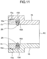
- FIG. 11 is a sectional view of a seal structure including a first ring holder, a second ring holder, and an O-ring;
- FIG. 12 illustrates a state that a guide of a rigid endoscope 2 is in contact with an opening of the guide connector of a washing sheath or a wiper sheath;
- FIG. 13 illustrates the guide that is being inserted into the guide connector
- FIG. 14 illustrates the guide connector and the guide in the engagement state thereof
- FIG. 15 illustrates the relationship between the first cam groove and the second cam groove with a pin positioned at a click pin standby position L 1 of the first cam groove
- FIG. 16 illustrates a wiper tube in a rotation state thereof and a wiper in an initial operation state thereof with the pin position at the location of FIG. 15 ;
- FIG. 17 illustrates the relationship between the first cam groove and the second cam groove when the pin shifts to within an axial motion range L 3 via a retraction motion range L 2 of the first cam groove;
- FIG. 18 illustrates the wiper tube in the rotation state thereof and the wiper in an axial motion state thereof with the pin positioned at the location of FIG. 17 ;
- FIG. 19 illustrates the relationship between the first cam groove and the second cam groove with the pin positioned in a wiping operation range L 4 of the first cam groove
- FIG. 20 illustrates the wiper tube in the rotation state thereof and the wiper in a wiping operation state thereof with the pin positioned at the location of FIG. 19 ;
- FIG. 21 illustrates the relationship between the first cam groove and the second cam groove with the pin positioned in the axial motion range L 5 ;
- FIG. 22 illustrates the wiper tube in the rotation state thereof and the wiper in the axial motion state thereof with the pin positioned at the location of FIG. 21 ;
- FIG. 23 illustrates the relationship between the first cam groove and the second cam groove when the pin is shifted to a click pin standby position L 7 via a retraction motion range L 6 of the first cam groove;
- FIG. 24 illustrates the wiper tube in the rotation state thereof and the wiper in the operation end state thereof with the pin positioned at the location of FIG. 23 ;
- FIG. 25 is a sectional view of another example of an end portion of a wiper sheath forming the endoscope system
- FIG. 26 is a perspective view illustrating the end portion of the wiper sheath with a light-entrance prevention member attached thereto;
- FIG. 27 is a perspective view of the light-entrance prevention member
- FIG. 28 illustrates the distal-end face of the wiper sheath with the rigid endoscope inserted therein viewed from the distal-end side;
- FIG. 29 is a sectional view of a sheath insert section including a holder to be engaged with a wiper shaft;
- FIG. 30 is a perspective view illustrating a modified example of the light-entrance prevention member
- FIG. 31 is a sectional view illustrating another example of the end portion of the wiper sheath forming the endoscope system
- FIG. 32 is a sectional view illustrating the relationship between the end portion of the wiper sheath and the insert section of the rigid endoscope.
- FIG. 33 is a sectional view of yet another example of the end portion of the wiper sheath forming the endoscope system.
- an endoscope system 1 includes a rigid endoscope 2 having a rigid insert section 2 A, a washing sheath 3 , and a wiper sheath 4 .
- An observation optical system and an illumination optical system are arranged toward a distal-end face 2 a of the rigid insert section 2 A from inside.
- the rigid insert section 2 A of the rigid endoscope 2 is inserted through a sheath insert section 3 A of the washing sheath 3 .
- the sheath insert section 3 A of the washing sheath 3 is inserted through a wiper insert section 4 A of a wiper sheath 4 .
- the rigid endoscope 2 includes the insert section 2 A, a grip section 2 B, and an eyepiece section 2 C.
- the rigid insert section 2 A is inserted into a body cavity of a subject.
- the grip section 2 B is arranged on the proximal end of the insert section 2 A.
- the eyepiece section 2 C is arranged on the proximal end of the grip section 2 B.
- the illumination optical system and the observation optical system are arranged within the insert section 2 A.
- the illumination optical system illuminates a region within an abdominal cavity of the subject.
- the observation optical system captures an observation image of the region within the abdominal cavity illuminated by the illumination optical system.
- the grip section 2 B is provided with a light-guide connector (not shown).
- the light-guide connector (not shown) connects to a connector arranged at one end of a light-guide cable.
- the other end of the light-guide cable connects to a light-source device. Illumination light from the light-source device is guided to the region within the abdominal cavity via the light-guide cable and the illumination optical system and illuminates the abdominal region.
- a camera head (not shown) containing a charge-coupled device (CCD) is able to be connected to the eyepiece section 2 C.
- the observation image of the region within the abdominal cavity is captured by the CCD in the camera head through the observation optical system.
- An electrical signal responsive to the observation image captured by the CCD is then supplied to a system controller (not shown).
- a guide portion 5 is protruded in the direction of insertion from a distal-end face of the insertion portion of the grip section 2 B.
- the washing sheath 3 includes the sheath insert section 3 A and the sheath grip section 3 B arranged on the proximal end side of the sheath insert section 3 A.
- the sheath insert section 3 A includes at an end portion of the sheath insert section 3 A a nozzle 3 b serving as an opening for supplying and sucking water.
- the insert section 2 A is inserted through an insert channel 3 c as an inner passage of the sheath insert section 3 A.
- the sheath grip section 3 B includes at the proximal end thereof an opening 3 D through which the insert section 2 A of the rigid endoscope 2 is inserted into the insert channel 3 C.
- the guide connector 6 is arranged on the circumference of the sheath grip section 3 B close to the proximal end thereof.
- a socket portion 6 b of the guide connector 6 is extended in perpendicular to the direction of insertion of the sheath grip section 3 B.
- the guide connector 6 includes an opening 6 a opening in the direction in which the insert section 2 A of the rigid endoscope 2 is inserted.
- the socket portion 6 b has a generally U-shape in plan view.
- a guide portion 7 protruding in the direction of insertion is arranged on the distal end of the sheath grip section 3 B.
- the guide portion 7 is engaged with a guide connector 8 arranged on an operation unit 4 B of the wiper sheath 4 . In this way, the washing sheath 3 and the wiper sheath 4 are reliably connected to each other.
- a water feed sleeve 3 c to be in communication with the insert channel 3 C is extended from the circumference of the sheath grip section 3 B.
- One end of a water feed tube (not shown) is connected to the water feed sleeve 3 c .
- the other end of the waver feed tube is connected to an injector serving as water feed means or sucking means.
- a liquid such as a cleaning liquid cleaning the distal-end face 2 a of the rigid endoscope 2 is fed to the water feed sleeve 3 c via the water feed tube by the injector. Water is also sucked out by the injector.
- the water feed means is not limited to an injector.
- the water feed means may be a water feeder.
- a nozzle 3 b is arranged to a distal end portion 3 a of the sheath insert section 3 A.
- the nozzle 3 b is formed by bending the distal end portion 3 a inward. The bent area is waved.
- the nozzle 3 b has a predetermined dimension so that the field of view of the rigid endoscope 2 is not narrowed, in other words, so that the observation window of the distal-end face 2 a of the insert section 2 A is not blocked.
- a slight gap serving as a liquid passage namely, an insertion gap (see 3 d of FIG. 16 and so on) remains between the inner circumference of the sheath insert section 3 A and the outer circumference of the insert section 2 A.
- the distal end of the insertion gap 3 d communicates with the distal end gap, and the proximal end of the insertion gap 3 d communicates with the injector via the water feed sleeve 3 C.
- the opening 3 D of the sheath grip section 3 B is loaded at an adequate location thereof with an O-ring (not shown). With the insert section 2 A inserted, the O-ring is tightened to the outer circumference of the insert section 2 A, thereby maintaining water-tightness on the proximal end of the insertion gap 3 d.
- the injector is operated with the insert section 2 A of the rigid endoscope 2 inserted in the insert channel 3 c of the sheath insert section 3 A.
- a liquid is fed from within the injector to the distal-end face 2 a of the insert section 2 A from all radial directions via the water feed sleeve 3 C, the insertion gap 3 d , and the distal end gap of the nozzle 3 b .
- the cleaning liquid thus cleans the distal-end face 2 a.
- the wiper sheath 4 includes the wiper insert section 4 A, a wiper 9 attached to the distal end of the wiper insert section 4 A, and the operation unit 4 B attached to the proximal end of the wiper insert section 4 A.
- the sheath insert section 3 A of the washing sheath 3 is inserted through the inner passage 4 a of the wiper insert section 4 A.
- the wiper 9 is used to wipe water ejected through the nozzle 3 b to the distal-end face 2 a of the insert section 2 A or water or a body fluid sticking to the distal-end face 2 a .
- the wiper 9 is arranged to be in contact with the distal-end face 2 a of the insert section 2 A within the sheath insert section 3 A.
- the operation unit 4 B is used to cause the wiper 9 to be in contact with the distal-end face 2 a to wipe water or body fluid sticking to the distal-end face 2 a .
- the operation unit 4 B is also used to move the wiper 9 in an arc to a far position spaced apart from the distal-end face 2 a .
- the wiper 9 is moved in an arc with respect to the distal-end face 2 a so that the wiper 9 is prevented from being in contact with the nozzle 3 b.
- the operation unit 4 B includes on the proximal end thereof an opening 4 C through which the sheath insert section 3 A of the washing sheath 3 is inserted.
- a guide connector 8 is arranged on the operation unit 4 B close to the opening 4 C.
- the guide connector 8 is similar in structure to the guide connector 6 of the washing sheath 3 .
- the guide connector 8 has an opening 8 a opened in the direction in which the sheath insert section 3 A of the washing sheath 3 is inserted.
- the guide connector 8 has a socket portion 8 b having a generally U-shape in plan view.
- a tubular holder 4 b is arranged within the inner passage 4 a of the wiper insert section 4 A.
- a wiper shaft 10 integrally formed with the wiper 9 is supported rotatably and movably in an arc by the tubular holder 4 b .
- a plurality of cutouts are made on the wiper insert section 4 A. For example, one cutout is made on the distal end of the wiper insert section 4 A and the other cutout is made on the proximal end of the wiper insert section 4 A.
- the tubular holders 4 b are respectively arranged in the cutouts. The holders 4 b with the wiper shaft 10 passing therethrough are then laser welded to the wiper insert section 4 A (see FIG. 29 ).
- the wiper 9 is integrally formed with the end of the wiper shaft 10 using insert molding.
- the wiper 9 made of flexible rubber, has a generally rectangular shape having a size large enough to wipe the observation window of the distal-end face 2 a and nearby.
- the wiper 9 is so thick that the wiper 9 in the bent state thereof is in contact with the distal-end face 2 a to wipe water and body fluids sticking to the distal-end face 2 a.
- the proximal end of the wiper shaft 10 is arranged in the operation unit 4 B.
- the operation unit 4 B is operated by a surgeon to pivot the wiper 9 .
- a drive force responsive to a pivotal motion by the surgeon is transferred to the wiper 9 via the wiper shaft 10 .
- the operation unit 4 B will be described later in more detail.
- the wiper 9 is placed into contact with the distal-end face 2 a of the rigid endoscope 2 arranged within the washing sheath 3 .
- the endoscope system 1 including the rigid endoscope 2 , the washing sheath 3 and the wiper sheath 4 , is set to be inserted in a trocar (not shown) during a surgical operation.
- the endoscope system 1 in the trocar is held within the body of a patient, and an observation image of a region within the abdominal cavity of the patient captured through the observation optical system is supplied to a system controller via a camera head.
- the wiper 9 in the wiper sheath 4 wipes water and body fluids sticking to the distal-end face 2 a of the rigid endoscope 2 set in the washing sheath 3 .
- the wiper 9 may touch the nozzle 3 b of the washing sheath 3 .
- the wiper 9 touches the nozzle 3 b , the wiper 9 can be damaged. If the wiping area of the wiper 9 is narrowed to overcome such a problem, there is a possibility that water or body fluids may remain within the field of view of the distal-end face 2 a.
- the operation unit 4 B forming the wiper sheath 4 in the endoscope system 1 of the embodiment is thus operated, wiping the water and the body fluids off the distal-end face 2 a while moving the wiper 9 in an arc with respect to the distal-end face 2 a away from the nozzle 3 b.
- the operation unit 4 B of FIGS. 3 through 5 includes a tubular body 11 , a wiper tube 12 supported rotatably and movably in an arc with respect to the body 11 , a first rotary ring 13 , a second rotary ring 14 , and first and second O-ring holders 15 and 16 arranged on the proximal end of the body 11 .
- the body 11 is secured to the proximal end of the wiper insert section 4 A.
- the wiper tube 12 includes a recess portion 12 A that locks a bent portion 10 A of the wiper shaft 10 on the proximal end thereof.
- the wiper shaft 10 is supported rotatably and movably in an arc within the wiper insert section 4 A.
- the first rotary ring 13 and the second rotary ring 14 house the body 11 and the wiper tube 12 within the inner circumferences thereof and are rotatably supported on the body 11 .
- the first rotary ring 13 and the second rotary ring 14 are rotatable and movable in an arc in engagement with the wiper tube 12 .
- the first and second O-ring holders 15 and 16 hold an O-ring 26 that maintains water-tightness in the proximal end of the wiper sheath 4 and the sheath insert section 3 A of the washing sheath 3 .
- two holes 20 A and a first cam groove 24 are arranged on predetermined locations on the outer circumference of the body 11 .
- the holes 20 A restrains a rotary motion of the wiper tube 12 .
- the first cam groove 24 restrains the longitudinal movement when the wiper tube 12 is pivoted. The specific shape of the first cam groove 24 will be described later.
- the hole 20 A receives a click pin 20 that is supported in a manner protrudable toward the inner circumference of the wiper tube 12 as shown in FIGS. 4 through 7 .
- the click pin 20 is continuously urged toward the body 11 by a click spring 21 loaded within the wiper tube 12 .
- the wiper tube 12 While the wiper tube 12 is pivoted, the click pin 20 is engaged with one of the holes 20 A, and the pivotal motion of the wiper tube 12 is thus limited. More specifically, the wiper tube 12 is pivotally movable within a range defined between the two holes 20 A as shown in FIG. 7 .
- the body 11 is provided with a stopper 27 at a predetermined location.
- the stopper 27 abuts a stop position 27 a of the second rotary ring 14 (see FIG. 7 )
- the wiper tube 12 is prevented from further pivoting from a pivot limit position determined by the hole 20 A and the click pin 20 .
- the body 11 includes an allowance recess portion 11 A having a predetermined width.
- the wiper shaft 10 is received in the allowance recess portion 11 A.
- the allowance recess portion 11 A receives the bent portion 10 A of the wiper shaft 10 locked by the recess portion 12 A of the wiper tube 12 while allowing the wiper tube 12 to rotate and move in an arc.
- the bent portion 10 A of the wiper shaft 10 is locked by the recess portion 12 A of the wiper tube 12 .
- Screw holes 12 a are arranged on both side areas of the recess portion 12 A.
- the recess portion 12 A is covered with a wiper retraining member 19 with the bent portion 10 A received in the recess portion 12 A.
- the wiper retraining member 19 is secured to the body 11 by tightening screws (not shown) into the screw holes 12 a.
- This arrangement prevents the bent portion 10 A of the wiper shaft 10 from coming off the recess portion 12 A.
- the wiper shaft 10 can thus move in an arc along with the wiper tube 12 .
- a pin 23 is arranged at a predetermined location on the circumference of the wiper tube 12 .
- the pin 23 is operatively engaged with the first cam groove 24 of the body 11 and a second cam groove 25 arranged on an extension portion 14 A of the second rotary ring 14 .
- the pin 23 thus guides the wiper tube 12 in the rotation and longitudinal movement thereof.
- the pin 23 passing through the wiper tube 12 at a predetermined location with one end protruding from the outer circumference of the wiper tube 12 by a predetermined length and the other end inwardly protruding from the inner circumference of the wiper tube 12 by a predetermined length.
- the one end of the pin 23 protruding from the outer circumference of the wiper tube 12 is received in the second cam groove 25 while the other end of the pin 23 inwardly protruding from the inner circumference of the wiper tube 12 is received in the first cam groove 24 .
- the shape of the second cam groove 25 will be specifically described later.
- the wiper tube 12 is urged toward the proximal end of the wiper sheath 4 by at least two springs 17 .
- the urging force of the springs 17 and the urging force of the wiper 9 are related as below.
- the urging force of the wiper 9 occurs when the wiper 9 is in contact with the distal-end face 2 a , and works in the direction of insertion of the wiper sheath 4 .
- the pin 23 is reliably engaged with the first cam groove 24 and the second cam groove 25 .
- the wiper tube 12 can thus perform the pivotal operation and the longitudinal movement operation in accordance with the shapes of the cam grooves 24 and 25 .
- the extension portion 14 A having the second cam groove 25 as shown in FIGS. 5 through 8 is integrally formed with the second rotary ring 14 .
- the extension portion 14 A is extended in the direction of insertion from the second rotary ring 14 at a predetermined location thereof.
- the second rotary ring 14 housing the body 11 and the wiper tube 12 with the pin 23 received in the second cam groove 25 of the extension portion 14 A, is assembled to the first rotary ring 13 .
- the first rotary ring 13 forms an outer housing of the operation unit 4 B to be rotated by a surgeon.
- the first rotary ring 13 has on the outer circumference knurled with a plurality of grooves 13 a to help the surgeon to grip and rotate easily the first rotary ring 13 .
- a fixing section 13 A is arranged on the distal-end face of the first rotary ring 13 .
- a ring-like seal member 18 is loaded onto the fixing section 13 A to maintain water-tightness in the interior of the first rotary ring 13 .
- the seal member 18 is integrally secured to the first rotary ring 13 by tightening a screw 22 A onto a fixing plate 22 .
- a ring-like seal member 18 is arranged on the proximal end of the second rotary ring 14 .
- the seal member 18 is secured to the second rotary ring 14 into a unitary body by screw tightening a fixing plate 22 .
- the guide connector 8 is arranged on the outer circumference of the second O-ring holder 16 .
- the guide connector 8 is secured to the second O-ring holder 16 into a unitary body.
- the second cam groove 25 receiving one end of the pin 23 is a generally V slot formed in the extension portion 14 A.
- the generally V shaped second cam groove 25 includes a second distal guide face 25 A forming the distal-end side and a second proximal guide face 25 B forming the proximal-end side.
- the first cam groove 24 receiving the other end of the pin 23 has a generally crank shape.
- the generally crank shaped first cam groove 24 includes a first distal guide face 24 A forming the distal-end side and a first proximal guide face 24 B forming the proximal-end side.
- the wiper tube 12 is continuously urged by the springs 17 toward the proximal end of the wiper sheath 4 .
- the pin 23 is received in the first cam groove 24 in engagement with the first proximal guide face 24 B.
- the pin 23 is guided in accordance with the shapes of the first cam groove 24 and the second cam groove 25 .
- the wiper tube 12 having the pin 23 fixed thereon is integrally moved with the pin 23 .
- the wiper shaft 10 having the bent portion 10 A received in the groove portion 12 A of the wiper tube 12 is thus rotated and moved in an arc.
- the wiper shaft 10 When the wiper tube 12 with the bent portion 10 A of the wiper shaft 10 fixed thereon is moved, the wiper shaft 10 is rotated and moved in an arc. Then, along with the wiper shaft 10 , the wiper 9 fixed to the wiper shaft 10 performs a wiping operation to wipe the distal-end face 2 a , and a retraction operation in which the wiper 9 is retracted from the nozzle 3 b of the washing sheath 3 by spacing apart from the distal-end face 2 a in a distant direction.
- FIG. 10 illustrates the relationship between the position of the pin 23 in the first cam groove 24 and the operation of the wiper 9 .
- the click pin 20 is received in the hole 20 A to put the wiper 9 to a standby state.
- the positions L 1 and L 7 are click pin standby positions.
- the position L 7 With the position L 1 set as a wiping operation start point, the position L 7 becomes a wiping operation end point at which the wiper tube 12 completes a wiping operation after traveling a predetermined direction, and the position L 7 then serves as a start point for a next wiping operation.
- the wiper 9 When the pin 23 is placed in one of ranges L 2 and L 6 of the first cam groove 24 , the wiper 9 is shifted to a far position from the distal-end face 2 a , thus, spaced apart from the nozzle 3 b of the washing sheath 3 .
- the ranges L 2 and L 6 are retraction ranges within which the wiper 9 is retracted from the observation field of view.
- the wiper 9 moves in the axial direction. That is, the ranges L 3 and L 5 are ranges within which the wiper 9 is axially moved.
- the wiper 9 moves from the far position to be in contact with the distal-end face 2 a .
- the wiper 9 is shifted from the contact state with the distal-end face 2 a to the far position.
- the range L 4 is a wiping operation range within which the wiper 9 wipes the fluids.
- the distance of the wiper 9 to the far position is determined by a length L 10
- a wiping range of the wiper 9 is determined by a length L 11 .
- the insert section 2 A of the rigid endoscope 2 of FIG. 1 is inserted through the sheath insert section 3 A of the washing sheath 3 .
- the guide portion 5 of the rigid endoscope 2 moving in the distal direction (as represented by an arrow “a”) is then brought into contact with the opening 6 a of the socket 6 forming the guide connector 6 of the washing sheath 3 .
- the sheath insert section 3 A of the washing sheath 3 having the rigid endoscope 2 remaining inserted therethrough is inserted into the wiper insert section 4 A of the wiper sheath 4 .
- the guide portion 7 of the washing sheath 3 is mated with the guide connector 8 of the wiper sheath 4 .
- the washing sheath 3 and the wiper sheath 4 are reliably connected to each other, and the endoscope system 1 is now assembled.
- the pin 23 is positioned at the click pin standby position L 1 of the first cam groove 24 .
- the click pin standby position L 1 is an initial position, and the wiper tube 12 in the operation unit 4 B remains at an angle of rotation ⁇ 3 as shown in FIG. 16 .
- the pin 23 makes an angle of ⁇ 1 with respect to the first cam groove 24 , and the pin 23 makes an angle of ⁇ 2 with respect to the second cam groove 25 .
- the surgeon rotates the operation unit 4 B clockwise to perform the wiping operation. Then, the pin 23 moves in accordance with the first cam groove 24 and the second cam groove 25 . More specifically, the pin 23 moves from the click pin standby position L 1 to the axial motion range L 3 via the retraction motion range L 2 of the first cam groove 24 as shown in FIG. 17 .
- the pin 23 moves from the click pin standby position L 1 to within the retraction motion range L 2 , sliding along the first proximal guide face 24 B of the first cam groove 24 .
- the wiper 9 is now approaching the distal-end face 2 a from the far position spaced apart from the nozzle 3 b of the washing sheath 3 .
- the wiper tube 12 within the operation unit 4 B is placed at an angle ⁇ 5 smaller than the previous angle ⁇ 3 as shown in FIG. 18 .
- the angle of the pin 23 with respect to the first cam groove 24 becomes a angle ⁇ 4 smaller than the previous angle ⁇ 1 .
- the wiper tube 12 is moved toward the proximal end of the wiper sheath 4 by the urging force of the springs 17 along the linear portion of the first cam groove 24 .
- the wiper 9 is brought into contact with the distal-end face 2 a.
- the surgeon further rotates the operation unit 4 B, thereby causing the pin 23 to move along the wiping operation range L 4 of the first cam groove 24 .
- the pin 23 moves within the wiping operation range L 4 in response to the rotation of the operation unit 4 B, thereby sliding along the second proximal guide face 25 B of the second cam groove 25 and the first proximal guide face 24 B of the first cam groove 24 .
- the wiper tube 12 rotates with the pin 23 remaining at the position at the end of the axial motion range L 3 .
- the wiper 9 wipes the distal-end face 2 a while moving in contact with the distal-end face 2 a.
- the wiper 9 performs the wiping operation within the wiping operation range L 4 .
- the wiper 9 wipes water and body fluids off the distal-end face 2 a , thereby assuring a good field of view.
- Cleaning operation of the nozzle 3 b of the washing sheath 3 may be performed throughout or in the middle of the rotation operation of the operation unit 4 B.
- a cleaning fluid is ejected through the nozzle 3 b .
- the wiper tube 12 is shifted in the distal direction of the wiper sheath 4 contrary to the motion within the axial motion range L 3 . More specifically, the wiper 9 is shifted from the contact state thereof with the distal-end face 2 a to the far position spaced apart from the distal-end face 2 a . The wiper 9 is now detached from the distal-end face 2 a.
- the wiper 9 thus goes out of the observation field of view in the state detached from the nozzle 3 b of the washing sheath 3 .
- the wiper 9 becomes a retraction state moving to the far position from the distal-end face 2 a.
- the wiper tube 12 within the operation unit 4 B is now held at an angle ⁇ 10 as shown in FIG. 24 .
- the pin 23 has an angle ⁇ 8 with respect to the first cam groove 24 , and an angle ⁇ 9 with respect to the second cam groove 25 .
- the surgeon may counterclockwise rotate the operation unit 4 B.
- the above-described process of the wiper 9 is reversed.
- the wiper 9 wipes water and body fluids off the distal-end face 2 a more sufficiently, and a sufficient field of view is thus assured.
- the wiper 9 wipes the distal-end face 2 a of the rigid endoscope 2 .
- the wiper 9 is spaced apart from the nozzle 3 b at the far position thereof separated from the distal-end face 2 a .
- the wiper 9 is brought into contact with the distal-end face 2 a .
- This arrangement allows the wiping area of the wiper 9 with respect to the distal-end face 2 a to be maximized. The water and the body fluids sticking to the distal-end face 2 a are efficiently wiped and removed. An excellent field of view is thus assured.
- the wiper 9 Since the wiper 9 slides on a desired area of the distal-end face 2 a without being in contact with the nozzle 3 b of the washing sheath 3 , the wiper 9 maintains a wiping performance in a manner free from damage for a long period of time. Since the wiper 9 remains free from contact with the nozzle 3 b , the force of the wiper 9 is easily adjusted.
- the endoscope system 1 has an air-tight mechanism to prevent the insufflation gas and the body fluid from leaking out through the operation unit 4 B.
- the endoscope system 1 includes the wiper shaft 10 within the wiper sheath 4 as shown in a lower portion of FIG. 5 .
- the rotation axis of the wiper shaft 10 is offset from the center axis of the wiper insert section 4 A of the wiper sheath 4 .
- This structure presents difficulty in maintaining water-tightness with the wiper 9 function. If the wiper sheath 4 including the wiper shaft 10 is water-tight sealed, a required torque of the wiper shaft 10 becomes large, thereby making operation difficult.
- the endoscope system 1 of the present embodiment employs a ring-shaped and sheet seal member 18 .
- the seal member 18 has an opening having a diameter equal to or slightly smaller than the outer diameter of the body 11 .
- Two seal members 18 are respectively arranged on the proximal end of the body 11 and the distal end of the body 11 .
- the seal members 18 are respectively secured to the first rotary ring 13 and the second rotary ring 14 to the predetermined state by tightening the screws 22 a onto the fixing plates 22 .
- Portions of the seal members 18 in contact with the outer circumference of the body 11 are preferably deformed to be tightly in contact with the body 11 on the proximal end and the distal end of the operation unit 4 B.
- the seal members 18 may be in contact with the outer circumference of the body 11 without being deformed.
- the use of the two seal members 18 allows the first rotary ring 13 and the second rotary ring 14 , namely, the interior of the operation unit 4 B to be water-tight sealed. This arrangement prevents the insufflation gas and the body fluid, which may flow out from within the abdominal cavity, from being leaked through the operation unit 4 B.
- the seal members 18 are ring-shaped sheets serving as a water-tight member. Therefore, the torque required for the rotation operation of the operation unit 4 B is not increased, and a small torque is sufficient to rotate the operation unit 4 B.
- the endoscope system 1 employs an O-ring 26 in areas free from the rotation motion of the operation unit 4 B to improve water-tightness.
- the O-ring 26 is held between the first O-ring holder 15 and the second O-ring holder 16 , and fixed within the second rotary ring 14 .
- the first O-ring holder 15 has a male thread on outer circumference 15 a on the distal end thereof.
- the second O-ring holder 16 has a female thread on inner circumference 16 a on the distal end thereof to be mated with the male thread on outer circumference 15 a.
- the first O-ring holder 15 has as the proximal end thereof a circular groove 15 A that receives the O-ring 26 .
- the second O-ring holder 16 has, at a step on the inner circumference thereof, an abutment portion 16 A engaging the O-ring 26 . That is, the O-ring 26 is thus squeezed between the circular groove 15 A and the abutment portion 16 A.
- the O-ring 26 is deformed to be uniformly protruded to the center axis of the second O-ring holder 16 .
- the O-ring 26 which is deformed under the pressure between the first O-ring holder 15 and the second O-ring holder 16 , is pressed into contact with the outer circumference of the sheath insert section 3 A to be inserted through the inner passage 4 b of the wiper sheath 4 . Water-tightness is thus assured. This arrangement prevents the insufflation gas and the body fluid from leaking out through the wiper insert section 4 A.
- the wiper sheath 4 includes the wiper 9 in the endoscope system 1 .
- the wiper sheath 4 is easily inserted into the abdominal cavity of the subject and the wiper 9 is protected.
- the wiper sheath 4 in an endoscope system 1 A of one embodiment of the present invention is rounded at the distal end portion thereof as a rounded end portion 4 d to facilitate insertion and to protect the wiper 9 .
- the tubular holder 4 c is arranged in the wiper insert section 4 A of the wiper sheath 4 to support the wiper shaft 10 in a manner that allows the wiper shaft 10 to be rotated and axially moved.
- a plurality of holders 4 c are arranged in the wiper insert section 4 A.
- two cutouts, one at the distal end and the other at the proximal end of the wiper insert section 4 A, are made, and then two holders 4 b are respectively laser welded in the two cutouts.
- the insert section 2 A of the rigid endoscope 2 is inserted through the wiper sheath 4 .
- the insertion position of the insert section 2 A of the rigid endoscope 2 is determined by the guide portion 5 that is mated with the guide connector 8 .
- the distal-end face 2 a of the rigid endoscope 2 includes an illumination window 2 c aligned with a distal-end face of a light-guide fiber as the illumination optical system, and an observation window 2 b forming the most distal end of the observation optical system including an image pickup device such as a charge-coupled device (CCD).
- an image pickup device such as a charge-coupled device (CCD).
- the illumination window 2 c and the observation window 2 b have a positional relationship as shown in FIG. 25 .
- the wiper sheath 4 has the rounded end portion 4 d . So, if illumination light is emitted from the illumination window 2 c as represented by a broken line, the illumination light is reflected from the inner circumference of the rounded end portion 4 d , and then incident on the observation window 2 b . An observation image may be destroyed.
- a light-entrance prevention member 30 is arranged on the inner circumference of the rounded end portion 4 d of the wiper sheath 4 in order to prevent the reflected light from entering the observation window 2 b .
- the light-entrance prevention member 30 may be one that guides the reflected light to another area rather than the observation window so that an observation image is free from the effect of the reflected light.
- the light-entrance prevention member 30 may have reflective characteristics, and may be curved to adhere to the inner circumference of the rounded end portion 4 d . As shown in FIG. 26 , the light-entrance prevention member 30 may adhere to the inner circumference of the rounded end portion 4 d of the light-entrance prevention member 30 . In this arrangement, a recess portion reflecting the illumination light is eliminated as shown in FIG. 25 , and the illumination light that is emitted from the illumination window 2 c as represented by broken line is reflected from the light-entrance prevention member 30 as represented by solid line. This arrangement prevents the reflected light from being incident on the observation window 2 b and an excellent observation image thus results. More specifically, the thickness of the light-entrance prevention member 30 is determined taking into consideration the projection of the rounded end portion 4 d from the inner circumference.
- the light-entrance prevention member 30 may be a light-entrance prevention member 30 A of FIG. 30 .
- the light-entrance prevention member 30 A includes an anti-reflection portion 30 B having anti-reflection characteristics and a position restraining portion 30 C.
- the position restraining portion 30 C integrally extends from the proximal end of the light-entrance prevention member 30 B and has a cutout 30 b on the underside thereof.
- the holder 4 b is arranged within the cutout 30 b . That is, the light-entrance prevention member 30 A may thus be used to position the wiper shaft 10 .
- the light-entrance prevention member 30 may be arranged so that the rounded end portion 4 d is moved to the distal-end face 2 a of the rigid endoscope 2 .
- the endoscope system 1 A does not employ the washing sheath 3 .
- the same advantages are provided even if the endoscope system 1 A employs the washing sheath 3 .
- the insert section 2 A of the rigid endoscope 2 When the insert section 2 A of the rigid endoscope 2 is inserted through the wiper insert section 4 A of the wiper sheath 4 in the endoscope system 1 A, a gap occurs between the inner circumference of the wiper insert section 4 A and the outer circumference of the insert section 2 A because the wiper shaft 10 is arranged within the wiper insert section 4 A. In this case, the insert section 2 A of the rigid endoscope 2 may be loose due to the gap. Then, when the wiper 9 is operated, the distal-end face 2 a of the rigid endoscope 2 becomes rattled, and the wiper 9 cannot reliably wipe the distal-end face 2 a because the wiper 9 cannot reliably move being in contact with the distal-end face 2 a.
- the endoscope system 1 B is described below with reference to FIGS. 31 through 33 .
- a portion of the inner circumference of the distal end of wiper insert section 4 A of the wiper sheath 4 forming the endoscope system 1 B is inwardly projected toward the center axis of the wiper sheath 4 as a position restraining projection 31 .
- the position restraining projection 31 extends entirely around the circumference of the wiper insert section 4 A at a predetermined location.
- the outer circumference of the insert section 2 A of the rigid endoscope 2 is brought into contact with the position restraining projection 31 as shown in FIG. 32 .
- the insert section 2 A is thus held within the wiper insert section 4 A in a manner free from rattling.
- the outer circumference of the insert section 2 A is also brought into contact with the holder 4 b provided in the wiper insert section 4 A, thereby holding the insert section 2 A in a more reliably manner.
- the position restraining projection 31 may be arranged in a predetermined location along the axial direction of the wiper insert section 4 A (for example, in the center portion of the wiper insert section 4 A), or at a plurality of locations within the wiper insert section 4 A.
- the position restraining projection may be the light-entrance prevention member 30 A discussed with reference to FIG. 30 .
- the light-entrance prevention member 30 A is thickened by a predetermined thickness.
- restraining portions 32 a having the same effect as the position restraining projection 31 results on both the distal end and the proximal end of the wiper insert section 4 A. When inserted through the wiper insert section 4 A, the insert section 2 A is reliably held within the wiper insert section 4 A.
- the endoscope system 1 B employs no washing sheath 3 .
- the same advantages are provided even if the endoscope system 1 B employs the washing sheath 3 .
- an endoscope system having a simple-structured, low-cost, and easy-to-use wiper is thus provided.
- first cam groove 24 and the second cam groove 25 are not limited to those described with reference to FIG. 10 .
- the first cam groove 24 and the second cam groove 25 may have any shape as long as the wiper 9 is reliably kept apart from the nozzle 3 b of the washing sheath 3 and moves along the distal-end face 2 a while in contact with the distal-end face 2 a.
Abstract
Description
Claims (8)
Applications Claiming Priority (2)
| Application Number | Priority Date | Filing Date | Title |
|---|---|---|---|
| JP2005036978A JP4472549B2 (en) | 2005-02-14 | 2005-02-14 | Endoscope device |
| JP2005-036978 | 2005-02-14 |
Publications (2)
| Publication Number | Publication Date |
|---|---|
| US20060199998A1 US20060199998A1 (en) | 2006-09-07 |
| US7959561B2 true US7959561B2 (en) | 2011-06-14 |
Family
ID=36944974
Family Applications (1)
| Application Number | Title | Priority Date | Filing Date |
|---|---|---|---|
| US11/353,521 Expired - Fee Related US7959561B2 (en) | 2005-02-14 | 2006-02-14 | Endoscope system having rigid endoscope and wiper sheath |
Country Status (2)
| Country | Link |
|---|---|
| US (1) | US7959561B2 (en) |
| JP (1) | JP4472549B2 (en) |
Cited By (23)
| Publication number | Priority date | Publication date | Assignee | Title |
|---|---|---|---|---|
| US20100249502A1 (en) * | 2008-10-29 | 2010-09-30 | Olympus Medical Systems Corp. | Medical instrument |
| US8460182B2 (en) | 2010-10-25 | 2013-06-11 | EndoSee Corporaton | Method and apparatus for hysteroscopy and endometrial biopsy |
| US8690764B2 (en) | 2010-10-20 | 2014-04-08 | Covidien Lp | Endoscope cleaner |
| US8708889B2 (en) | 2011-10-24 | 2014-04-29 | Trocare, LLC | Jawed trocar assembly |
| US20160360955A1 (en) * | 2015-06-11 | 2016-12-15 | Stelian Valeriu GEORGIAN | Laparoscopic eye wiper |
| US20170252056A1 (en) * | 2016-03-01 | 2017-09-07 | Mission Surgical Innovations, LLC | Surgical device including a cannula having a combination track |
| US9763567B2 (en) | 2010-10-20 | 2017-09-19 | Covidien Lp | Endoscope wiper blade cleaner |
| US10362926B2 (en) | 2012-06-25 | 2019-07-30 | Coopersurgical, Inc. | Low-cost instrument for endoscopically guided operative procedures |
| US10702305B2 (en) | 2016-03-23 | 2020-07-07 | Coopersurgical, Inc. | Operative cannulas and related methods |
| US10709321B2 (en) | 2016-07-13 | 2020-07-14 | Washington University | Self-cleaning endoscope |
| US10791918B1 (en) | 2019-10-04 | 2020-10-06 | ClearCam Inc. | Imaging element cleaning apparatus |
| US10959610B1 (en) | 2019-10-04 | 2021-03-30 | Clearcam Inc | Imaging element cleaning apparatus with structure-mandated cleaning member motion control |
| US10993609B1 (en) * | 2021-01-23 | 2021-05-04 | ClearCam Inc. | Imaging element cleaning device with imaging device fitment adjustability |
| US11013399B1 (en) | 2020-01-27 | 2021-05-25 | Board Of Regents, The University Of Texas System | Wiper assembly for imaging element cleaning apparatus |
| US11033179B1 (en) * | 2020-06-12 | 2021-06-15 | ClearCam Inc. | Method for placement of an imaging element cleaning apparatus and obturator for enabling same |
| US11058291B2 (en) | 2018-11-29 | 2021-07-13 | Board Of Regents, The University Of Texas System | Devices, systems and methods for cleaning of elongated instrument surface |
| US11109940B1 (en) * | 2021-02-09 | 2021-09-07 | ClearCam Inc. | Devices, apparatuses, systems and methods for facilitating cleaning of an imaging element of an imaging device |
| US11357542B2 (en) | 2019-06-21 | 2022-06-14 | Covidien Lp | Valve assembly and retainer for surgical access assembly |
| US11375887B2 (en) | 2019-10-04 | 2022-07-05 | ClearCam Inc. | Imaging element cleaning apparatus |
| US11412921B2 (en) | 2018-10-02 | 2022-08-16 | Covidien Lp | Multi lumen access device |
| US11707189B1 (en) | 2022-02-10 | 2023-07-25 | ClearCam Inc. | Methods, devices and systems for cleaning an imaging element with a translatable cleaning element |
| US11766309B2 (en) | 2021-03-09 | 2023-09-26 | ClearCam Inc. | Articles, kits and methods adapted for facilitating adjustability of operative apparatuses |
| US11850106B2 (en) | 2020-05-06 | 2023-12-26 | Covidien Lp | Cleaning cap for a surgical access device |
Families Citing this family (29)
| Publication number | Priority date | Publication date | Assignee | Title |
|---|---|---|---|---|
| US8579807B2 (en) | 2008-04-28 | 2013-11-12 | Ethicon Endo-Surgery, Inc. | Absorbing fluids in a surgical access device |
| US8690831B2 (en) | 2008-04-25 | 2014-04-08 | Ethicon Endo-Surgery, Inc. | Gas jet fluid removal in a trocar |
| WO2008007355A1 (en) * | 2006-07-13 | 2008-01-17 | Stark Med Gmbh | Trans-douglas endoscopical surgical device (ted) |
| US8100929B2 (en) | 2007-06-29 | 2012-01-24 | Ethicon Endo-Surgery, Inc. | Duckbill seal with fluid drainage feature |
| US7976501B2 (en) | 2007-12-07 | 2011-07-12 | Ethicon Endo-Surgery, Inc. | Trocar seal with reduced contact area |
| WO2009114807A1 (en) * | 2008-03-13 | 2009-09-17 | Mettler-Toledo Autochem, Inc. | Window scraper for an optical instrument |
| US8550988B2 (en) * | 2008-04-21 | 2013-10-08 | Covidien Lp | Endoscopic cleaner |
| US8870747B2 (en) | 2008-04-28 | 2014-10-28 | Ethicon Endo-Surgery, Inc. | Scraping fluid removal in a surgical access device |
| USD700326S1 (en) | 2008-04-28 | 2014-02-25 | Ethicon Endo-Surgery, Inc. | Trocar housing |
| US8568362B2 (en) | 2008-04-28 | 2013-10-29 | Ethicon Endo-Surgery, Inc. | Surgical access device with sorbents |
| US11235111B2 (en) | 2008-04-28 | 2022-02-01 | Ethicon Llc | Surgical access device |
| US8636686B2 (en) | 2008-04-28 | 2014-01-28 | Ethicon Endo-Surgery, Inc. | Surgical access device |
| US8273060B2 (en) | 2008-04-28 | 2012-09-25 | Ethicon Endo-Surgery, Inc. | Fluid removal in a surgical access device |
| US9358041B2 (en) | 2008-04-28 | 2016-06-07 | Ethicon Endo-Surgery, Llc | Wicking fluid management in a surgical access device |
| US7981092B2 (en) | 2008-05-08 | 2011-07-19 | Ethicon Endo-Surgery, Inc. | Vibratory trocar |
| DE102009037317A1 (en) * | 2009-08-14 | 2011-02-17 | Karl Storz Gmbh & Co. Kg | Device and method for centering the inner and outer tubes of an endoscope |
| US20110230711A1 (en) * | 2010-03-16 | 2011-09-22 | Kano Akihito | Endoscopic Surgical Instrument |
| US8460180B1 (en) * | 2010-04-16 | 2013-06-11 | Hector Zarate | Endoscopic lens cleaner |
| CN104093348B (en) * | 2012-09-14 | 2016-07-06 | 奥林巴斯株式会社 | Endoscope cleaning sheath and endoscope apparatus |
| DE102013102024A1 (en) * | 2013-02-01 | 2014-08-21 | Firma Trokamed Gmbh | arthroscopy shaft |
| CN105491938B (en) | 2013-09-26 | 2018-11-23 | 捷锐士阿希迈公司(以奥林巴斯美国外科技术名义) | endoscope sheath arm |
| US9585547B2 (en) | 2014-11-24 | 2017-03-07 | Gyrus Acmi, Inc. | Adjustable endoscope sheath |
| US9345386B1 (en) | 2014-11-24 | 2016-05-24 | Gyrus Acmi, Inc. | Adjustable endoscope sheath |
| US9782525B2 (en) | 2015-01-08 | 2017-10-10 | Gyrus Acmi, Inc. | Multi-way valve for a medical instrument |
| ITUA20163961A1 (en) | 2016-05-31 | 2017-12-01 | Medacta Int Sa | arthroscope |
| EP3752039A4 (en) | 2018-02-15 | 2021-09-29 | Covidien LP | Sheath assembly for a rigid endoscope |
| CN216933124U (en) * | 2019-03-18 | 2022-07-12 | Hoya株式会社 | Endoscope device |
| WO2021236945A1 (en) * | 2020-05-20 | 2021-11-25 | Arthrex, Inc. | Endoscopic camera sheath |
| WO2023026118A1 (en) * | 2021-08-26 | 2023-03-02 | Covidien Lp | In-situ scope cleaner |
Citations (13)
| Publication number | Priority date | Publication date | Assignee | Title |
|---|---|---|---|---|
| JPH04362912A (en) | 1991-01-10 | 1992-12-15 | Olympus Optical Co Ltd | Rotary action tool device for endoscope |
| US5313934A (en) * | 1992-09-10 | 1994-05-24 | Deumed Group Inc. | Lens cleaning means for invasive viewing medical instruments |
| JPH06189893A (en) | 1992-10-27 | 1994-07-12 | Olympus Optical Co Ltd | Endoscope device |
| US5392766A (en) | 1993-10-06 | 1995-02-28 | Innerdyne Medical, Inc. | System and method for cleaning viewing scope lenses |
| JPH0829699A (en) | 1994-07-11 | 1996-02-02 | Kitagawa Ind Co Ltd | Image scope |
| US5518502A (en) * | 1994-06-08 | 1996-05-21 | The United States Surgical Corporation | Compositions, methods and apparatus for inhibiting fogging of endoscope lenses |
| US5830126A (en) * | 1996-06-14 | 1998-11-03 | Machida Endoscope Co., Ltd. | Endoscope unit |
| US6126592A (en) * | 1998-09-12 | 2000-10-03 | Smith & Nephew, Inc. | Endoscope cleaning and irrigation sheath |
| JP2002224014A (en) | 2000-11-29 | 2002-08-13 | Olympus Optical Co Ltd | Stain remover for endoscope |
| JP2003199703A (en) | 2001-12-28 | 2003-07-15 | Olympus Optical Co Ltd | Sheath for endoscope |
| JP2003310628A (en) | 2002-04-18 | 2003-11-05 | Olympus Optical Co Ltd | In-vivo tissue collection device |
| US20040267090A1 (en) * | 2003-05-27 | 2004-12-30 | Haruhiko Ueno | Endoscope |
| JP4362912B2 (en) | 1999-12-08 | 2009-11-11 | ソニー株式会社 | IC card |
-
2005
- 2005-02-14 JP JP2005036978A patent/JP4472549B2/en not_active Expired - Fee Related
-
2006
- 2006-02-14 US US11/353,521 patent/US7959561B2/en not_active Expired - Fee Related
Patent Citations (14)
| Publication number | Priority date | Publication date | Assignee | Title |
|---|---|---|---|---|
| JPH04362912A (en) | 1991-01-10 | 1992-12-15 | Olympus Optical Co Ltd | Rotary action tool device for endoscope |
| US5313934A (en) * | 1992-09-10 | 1994-05-24 | Deumed Group Inc. | Lens cleaning means for invasive viewing medical instruments |
| JPH06189893A (en) | 1992-10-27 | 1994-07-12 | Olympus Optical Co Ltd | Endoscope device |
| US5392766A (en) | 1993-10-06 | 1995-02-28 | Innerdyne Medical, Inc. | System and method for cleaning viewing scope lenses |
| US5518502A (en) * | 1994-06-08 | 1996-05-21 | The United States Surgical Corporation | Compositions, methods and apparatus for inhibiting fogging of endoscope lenses |
| JPH0829699A (en) | 1994-07-11 | 1996-02-02 | Kitagawa Ind Co Ltd | Image scope |
| US5830126A (en) * | 1996-06-14 | 1998-11-03 | Machida Endoscope Co., Ltd. | Endoscope unit |
| US6126592A (en) * | 1998-09-12 | 2000-10-03 | Smith & Nephew, Inc. | Endoscope cleaning and irrigation sheath |
| JP4362912B2 (en) | 1999-12-08 | 2009-11-11 | ソニー株式会社 | IC card |
| JP2002224014A (en) | 2000-11-29 | 2002-08-13 | Olympus Optical Co Ltd | Stain remover for endoscope |
| JP2003199703A (en) | 2001-12-28 | 2003-07-15 | Olympus Optical Co Ltd | Sheath for endoscope |
| US20030139649A1 (en) * | 2001-12-28 | 2003-07-24 | Olympus Optical Co., Ltd. | Endoscope-covering sheath and blood vessel harvesting apparatus using the same |
| JP2003310628A (en) | 2002-04-18 | 2003-11-05 | Olympus Optical Co Ltd | In-vivo tissue collection device |
| US20040267090A1 (en) * | 2003-05-27 | 2004-12-30 | Haruhiko Ueno | Endoscope |
Cited By (48)
| Publication number | Priority date | Publication date | Assignee | Title |
|---|---|---|---|---|
| US8088065B2 (en) * | 2008-10-29 | 2012-01-03 | Olympus Medical Systems Corp. | Medical instrument |
| US20100249502A1 (en) * | 2008-10-29 | 2010-09-30 | Olympus Medical Systems Corp. | Medical instrument |
| US10335021B2 (en) | 2010-10-20 | 2019-07-02 | Covidien Lp | Endoscope wiper blade cleaner |
| US8690764B2 (en) | 2010-10-20 | 2014-04-08 | Covidien Lp | Endoscope cleaner |
| US9763567B2 (en) | 2010-10-20 | 2017-09-19 | Covidien Lp | Endoscope wiper blade cleaner |
| US8460182B2 (en) | 2010-10-25 | 2013-06-11 | EndoSee Corporaton | Method and apparatus for hysteroscopy and endometrial biopsy |
| US10441134B2 (en) | 2011-05-03 | 2019-10-15 | Coopersurgical, Inc. | Method and apparatus for hysteroscopy and endometrial biopsy |
| US8708889B2 (en) | 2011-10-24 | 2014-04-29 | Trocare, LLC | Jawed trocar assembly |
| US9662133B2 (en) | 2011-10-24 | 2017-05-30 | Trocare Llc | Jawed tip assembly |
| US10362926B2 (en) | 2012-06-25 | 2019-07-30 | Coopersurgical, Inc. | Low-cost instrument for endoscopically guided operative procedures |
| US20160360955A1 (en) * | 2015-06-11 | 2016-12-15 | Stelian Valeriu GEORGIAN | Laparoscopic eye wiper |
| US11490800B2 (en) * | 2015-06-11 | 2022-11-08 | Stelian Valeriu GEORGIAN | Laparoscopic eye wiper |
| US20170252056A1 (en) * | 2016-03-01 | 2017-09-07 | Mission Surgical Innovations, LLC | Surgical device including a cannula having a combination track |
| US11452538B2 (en) * | 2016-03-01 | 2022-09-27 | Mission Surgical Innovations, LLC | Surgical device including a cannula having a combination track |
| US10702305B2 (en) | 2016-03-23 | 2020-07-07 | Coopersurgical, Inc. | Operative cannulas and related methods |
| US10709321B2 (en) | 2016-07-13 | 2020-07-14 | Washington University | Self-cleaning endoscope |
| US11412921B2 (en) | 2018-10-02 | 2022-08-16 | Covidien Lp | Multi lumen access device |
| US20210290048A1 (en) * | 2018-11-29 | 2021-09-23 | Board Of Regents, The University Of Texas System | Devices, systems and methods for cleaning of elongated instrument surface |
| US11877729B2 (en) * | 2018-11-29 | 2024-01-23 | Board Of Regents, The University Of Texas System | Devices, systems and methods for cleaning of elongated instrument surface |
| US11058291B2 (en) | 2018-11-29 | 2021-07-13 | Board Of Regents, The University Of Texas System | Devices, systems and methods for cleaning of elongated instrument surface |
| US11357542B2 (en) | 2019-06-21 | 2022-06-14 | Covidien Lp | Valve assembly and retainer for surgical access assembly |
| US11707187B2 (en) | 2019-10-04 | 2023-07-25 | ClearCam Inc. | Imaging element cleaning apparatus |
| US10791918B1 (en) | 2019-10-04 | 2020-10-06 | ClearCam Inc. | Imaging element cleaning apparatus |
| US11284789B2 (en) | 2019-10-04 | 2022-03-29 | ClearCam, Inc. | Imaging element cleaning apparatus with structure-mandated cleaning member motion control |
| US11375887B2 (en) | 2019-10-04 | 2022-07-05 | ClearCam Inc. | Imaging element cleaning apparatus |
| US11707188B2 (en) | 2019-10-04 | 2023-07-25 | ClearCam Inc. | Imaging element cleaning apparatus with structure-mandated cleaning member motion control |
| US10932661B1 (en) | 2019-10-04 | 2021-03-02 | ClearCam Inc. | Imaging element cleaning apparatus |
| US10959610B1 (en) | 2019-10-04 | 2021-03-30 | Clearcam Inc | Imaging element cleaning apparatus with structure-mandated cleaning member motion control |
| US11013399B1 (en) | 2020-01-27 | 2021-05-25 | Board Of Regents, The University Of Texas System | Wiper assembly for imaging element cleaning apparatus |
| US11172813B2 (en) | 2020-01-27 | 2021-11-16 | Board Of Regents, The University Of Texas System | Wiper assembly for imaging element cleaning apparatus |
| US20220175236A1 (en) * | 2020-01-27 | 2022-06-09 | Board Of Regents, The University Of Texas System | Wiper assembly for imaging element cleaning apparatus |
| US11737661B2 (en) * | 2020-01-27 | 2023-08-29 | Board Of Regents, The University Of Texas System | Wiper assembly for imaging element cleaning apparatus |
| US11850106B2 (en) | 2020-05-06 | 2023-12-26 | Covidien Lp | Cleaning cap for a surgical access device |
| US11723527B2 (en) * | 2020-06-12 | 2023-08-15 | ClearCam Inc. | Method for placement of an imaging element cleaning apparatus and obturator for enabling same |
| US11717145B2 (en) * | 2020-06-12 | 2023-08-08 | ClearCam Inc. | Method for placement of an imaging element cleaning apparatus and obturator for enabling same |
| WO2021252315A1 (en) * | 2020-06-12 | 2021-12-16 | ClearCam Inc. | Method for placement of an imaging element cleaning apparatus and obturator |
| US20210386281A1 (en) * | 2020-06-12 | 2021-12-16 | ClearCam Inc. | Method for placement of an imaging element cleaning apparatus and obturator for enabling same |
| US20230337901A1 (en) * | 2020-06-12 | 2023-10-26 | ClearCam Inc. | Method for placement of an imaging element cleaning apparatus and obturator for enabling same |
| US11033179B1 (en) * | 2020-06-12 | 2021-06-15 | ClearCam Inc. | Method for placement of an imaging element cleaning apparatus and obturator for enabling same |
| US20220233064A1 (en) * | 2021-01-23 | 2022-07-28 | ClearCam Inc. | Imaging element cleaning device with imaging device fitment adjustability |
| US10993609B1 (en) * | 2021-01-23 | 2021-05-04 | ClearCam Inc. | Imaging element cleaning device with imaging device fitment adjustability |
| US11819197B2 (en) * | 2021-01-23 | 2023-11-21 | ClearCam, Inc. | Imaging element cleaning device with imaging device fitment adjustability |
| WO2022159365A1 (en) * | 2021-01-23 | 2022-07-28 | ClearCam Inc. | Imaging element cleaning device with imaging device fitment adjustability |
| US11109940B1 (en) * | 2021-02-09 | 2021-09-07 | ClearCam Inc. | Devices, apparatuses, systems and methods for facilitating cleaning of an imaging element of an imaging device |
| US11857382B2 (en) * | 2021-02-09 | 2024-01-02 | ClearCam, Inc. | Devices, apparatuses, systems and methods for facilitating cleaning of an imaging element of an imaging device |
| US20220249196A1 (en) * | 2021-02-09 | 2022-08-11 | ClearCam Inc. | Devices, apparatuses, systems and methods for facilitating cleaning of an imaging element of an imaging device |
| US11766309B2 (en) | 2021-03-09 | 2023-09-26 | ClearCam Inc. | Articles, kits and methods adapted for facilitating adjustability of operative apparatuses |
| US11707189B1 (en) | 2022-02-10 | 2023-07-25 | ClearCam Inc. | Methods, devices and systems for cleaning an imaging element with a translatable cleaning element |
Also Published As
| Publication number | Publication date |
|---|---|
| JP2006218240A (en) | 2006-08-24 |
| US20060199998A1 (en) | 2006-09-07 |
| JP4472549B2 (en) | 2010-06-02 |
Similar Documents
| Publication | Publication Date | Title |
|---|---|---|
| US7959561B2 (en) | Endoscope system having rigid endoscope and wiper sheath | |
| US5460168A (en) | Endoscope cover assembly and cover-system endoscope | |
| US8177717B2 (en) | Ultrasonic endoscope | |
| US20090062615A1 (en) | Endoscope with focal length varying function | |
| US10010242B2 (en) | Endoscope | |
| EP2404541B1 (en) | ENDOSCOPE with cable winding element | |
| US20060195016A1 (en) | Endoscope apparatus | |
| US20120053410A1 (en) | Endoscope, mantle tube, and endoscope system | |
| US20070066870A1 (en) | Hood for endoscope | |
| CN103027654B (en) | For open-ended locking device | |
| JP2007130084A (en) | Endoscopic sheath, and endoscopic system using endoscopic sheath | |
| CN111970951A (en) | Endoscope and method for attaching elongated member | |
| JPS6029125A (en) | Light source device of endoscope | |
| JP3855616B2 (en) | Endoscope | |
| CA2285743C (en) | Directional endoscopic surgical device | |
| JPWO2019093240A1 (en) | Detachment tool for the hood of the endoscope and a set of the removal tool for the hood and the hood | |
| US20160373624A1 (en) | Endoscope and cylindrical structure for endoscope | |
| JPH05184534A (en) | Endoscope | |
| US20090299222A1 (en) | Guide wire treatment tool | |
| JP3394617B2 (en) | Cover-type endoscope | |
| CN220192965U (en) | Video tube and endoscope | |
| US20220125279A1 (en) | Overtube, insertion apparatus having overtube attached and detached thereto, and method for attaching overtube to and detaching overtube from insertion apparatus | |
| JP4789317B2 (en) | Endoscope device | |
| JP3555356B2 (en) | Guide device for medical instruments with flexible cord | |
| CN108040463B (en) | Endoscope, cap, and cap forming method |
Legal Events
| Date | Code | Title | Description |
|---|---|---|---|
| AS | Assignment |
Owner name: OLYMPUS MEDICAL SYSTEMS CORP., JAPAN Free format text: ASSIGNMENT OF ASSIGNORS INTEREST;ASSIGNORS:AKUI, NOBUAKI;BANJU, KAZUO;DEJIMA, TAKUMI;REEL/FRAME:017896/0742 Effective date: 20060214 |
|
| FEPP | Fee payment procedure |
Free format text: PAYOR NUMBER ASSIGNED (ORIGINAL EVENT CODE: ASPN); ENTITY STATUS OF PATENT OWNER: LARGE ENTITY |
|
| STCF | Information on status: patent grant |
Free format text: PATENTED CASE |
|
| FPAY | Fee payment |
Year of fee payment: 4 |
|
| AS | Assignment |
Owner name: OLYMPUS CORPORATION, JAPAN Free format text: ASSIGNMENT OF ASSIGNORS INTEREST;ASSIGNOR:OLYMPUS MEDICAL SYSTEMS CORP.;REEL/FRAME:036276/0543 Effective date: 20150401 |
|
| AS | Assignment |
Owner name: OLYMPUS CORPORATION, JAPAN Free format text: CHANGE OF ADDRESS;ASSIGNOR:OLYMPUS CORPORATION;REEL/FRAME:039344/0502 Effective date: 20160401 |
|
| FEPP | Fee payment procedure |
Free format text: MAINTENANCE FEE REMINDER MAILED (ORIGINAL EVENT CODE: REM.); ENTITY STATUS OF PATENT OWNER: LARGE ENTITY |
|
| LAPS | Lapse for failure to pay maintenance fees |
Free format text: PATENT EXPIRED FOR FAILURE TO PAY MAINTENANCE FEES (ORIGINAL EVENT CODE: EXP.); ENTITY STATUS OF PATENT OWNER: LARGE ENTITY |
|
| STCH | Information on status: patent discontinuation |
Free format text: PATENT EXPIRED DUE TO NONPAYMENT OF MAINTENANCE FEES UNDER 37 CFR 1.362 |
|
| FP | Lapsed due to failure to pay maintenance fee |
Effective date: 20190614 |